US10523301B2 - Method and apparatus for focused data communications - Google Patents
Method and apparatus for focused data communicationsDownload PDFInfo
- Publication number
- US10523301B2 US10523301B2US15/649,187US201715649187AUS10523301B2US 10523301 B2US10523301 B2US 10523301B2US 201715649187 AUS201715649187 AUS 201715649187AUS 10523301 B2US10523301 B2US 10523301B2
- Authority
- US
- United States
- Prior art keywords
- signal
- antenna elements
- client devices
- antenna
- array controller
- Prior art date
- Legal status (The legal status is an assumption and is not a legal conclusion. Google has not performed a legal analysis and makes no representation as to the accuracy of the status listed.)
- Active
Links
Images


Classifications
- H—ELECTRICITY
- H04—ELECTRIC COMMUNICATION TECHNIQUE
- H04B—TRANSMISSION
- H04B7/00—Radio transmission systems, i.e. using radiation field
- H04B7/02—Diversity systems; Multi-antenna system, i.e. transmission or reception using multiple antennas
- H04B7/04—Diversity systems; Multi-antenna system, i.e. transmission or reception using multiple antennas using two or more spaced independent antennas
- H04B7/06—Diversity systems; Multi-antenna system, i.e. transmission or reception using multiple antennas using two or more spaced independent antennas at the transmitting station
- H04B7/0686—Hybrid systems, i.e. switching and simultaneous transmission
- H04B7/0695—Hybrid systems, i.e. switching and simultaneous transmission using beam selection
- H—ELECTRICITY
- H04—ELECTRIC COMMUNICATION TECHNIQUE
- H04B—TRANSMISSION
- H04B7/00—Radio transmission systems, i.e. using radiation field
- H04B7/02—Diversity systems; Multi-antenna system, i.e. transmission or reception using multiple antennas
- H04B7/04—Diversity systems; Multi-antenna system, i.e. transmission or reception using multiple antennas using two or more spaced independent antennas
- H04B7/06—Diversity systems; Multi-antenna system, i.e. transmission or reception using multiple antennas using two or more spaced independent antennas at the transmitting station
- H04B7/0602—Diversity systems; Multi-antenna system, i.e. transmission or reception using multiple antennas using two or more spaced independent antennas at the transmitting station using antenna switching
- H04B7/0608—Antenna selection according to transmission parameters
- H04B7/061—Antenna selection according to transmission parameters using feedback from receiving side
- H—ELECTRICITY
- H04—ELECTRIC COMMUNICATION TECHNIQUE
- H04B—TRANSMISSION
- H04B7/00—Radio transmission systems, i.e. using radiation field
- H04B7/02—Diversity systems; Multi-antenna system, i.e. transmission or reception using multiple antennas
- H04B7/04—Diversity systems; Multi-antenna system, i.e. transmission or reception using multiple antennas using two or more spaced independent antennas
- H04B7/06—Diversity systems; Multi-antenna system, i.e. transmission or reception using multiple antennas using two or more spaced independent antennas at the transmitting station
- H04B7/0613—Diversity systems; Multi-antenna system, i.e. transmission or reception using multiple antennas using two or more spaced independent antennas at the transmitting station using simultaneous transmission
- H04B7/0615—Diversity systems; Multi-antenna system, i.e. transmission or reception using multiple antennas using two or more spaced independent antennas at the transmitting station using simultaneous transmission of weighted versions of same signal
- H04B7/0617—Diversity systems; Multi-antenna system, i.e. transmission or reception using multiple antennas using two or more spaced independent antennas at the transmitting station using simultaneous transmission of weighted versions of same signal for beam forming
- H—ELECTRICITY
- H04—ELECTRIC COMMUNICATION TECHNIQUE
- H04B—TRANSMISSION
- H04B7/00—Radio transmission systems, i.e. using radiation field
- H04B7/02—Diversity systems; Multi-antenna system, i.e. transmission or reception using multiple antennas
- H04B7/04—Diversity systems; Multi-antenna system, i.e. transmission or reception using multiple antennas using two or more spaced independent antennas
- H04B7/06—Diversity systems; Multi-antenna system, i.e. transmission or reception using multiple antennas using two or more spaced independent antennas at the transmitting station
- H04B7/0613—Diversity systems; Multi-antenna system, i.e. transmission or reception using multiple antennas using two or more spaced independent antennas at the transmitting station using simultaneous transmission
- H04B7/0615—Diversity systems; Multi-antenna system, i.e. transmission or reception using multiple antennas using two or more spaced independent antennas at the transmitting station using simultaneous transmission of weighted versions of same signal
- H04B7/0619—Diversity systems; Multi-antenna system, i.e. transmission or reception using multiple antennas using two or more spaced independent antennas at the transmitting station using simultaneous transmission of weighted versions of same signal using feedback from receiving side
- H—ELECTRICITY
- H04—ELECTRIC COMMUNICATION TECHNIQUE
- H04B—TRANSMISSION
- H04B7/00—Radio transmission systems, i.e. using radiation field
- H04B7/02—Diversity systems; Multi-antenna system, i.e. transmission or reception using multiple antennas
- H04B7/04—Diversity systems; Multi-antenna system, i.e. transmission or reception using multiple antennas using two or more spaced independent antennas
- H04B7/06—Diversity systems; Multi-antenna system, i.e. transmission or reception using multiple antennas using two or more spaced independent antennas at the transmitting station
- H04B7/0686—Hybrid systems, i.e. switching and simultaneous transmission
- H04B7/0691—Hybrid systems, i.e. switching and simultaneous transmission using subgroups of transmit antennas
- H—ELECTRICITY
- H04—ELECTRIC COMMUNICATION TECHNIQUE
- H04W—WIRELESS COMMUNICATION NETWORKS
- H04W4/00—Services specially adapted for wireless communication networks; Facilities therefor
- H04W4/02—Services making use of location information
- H—ELECTRICITY
- H04—ELECTRIC COMMUNICATION TECHNIQUE
- H04W—WIRELESS COMMUNICATION NETWORKS
- H04W4/00—Services specially adapted for wireless communication networks; Facilities therefor
- H04W4/02—Services making use of location information
- H04W4/029—Location-based management or tracking services
Definitions
- the present inventionrelates generally to data communications.
- a method and apparatus for focused communicationincludes a base transmitter array in communication with at least one client device.
- the base transmitter arrayprovides a focused data communication to the client device.
- FIG. 1is an example system diagram of a focused data communications system including a client device and a base transmitter array;
- FIG. 2is another example system diagram of a focused data communications system including a plurality of client devices
- FIG. 3is another example system diagram of a focused data communications system including a moving client device
- FIG. 4is a flow diagram of an example method of providing focused data communications
- FIG. 5is an example functional block diagram of an antenna element processor in accordance with an embodiment
- FIG. 6is an example functional block diagram of an array controller in accordance with an embodiment
- FIG. 7is an example functional block diagram of a client device in accordance with an embodiment
- FIGS. 8A-8Fare example system diagrams of a focused data communications base transmitter array during detection of a new client device
- FIG. 9shows an example array coverage of a focused data communications system
- FIGS. 10A-10Care example diagrams of directivity and location embodiments of a focused communications system.
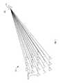
- FIG. 1is an example system diagram of a focused data communications system 100 including a client device 110 and a base transmitter array 120 .
- the base transmitter array 120includes a plurality of antennas 121 . It should be noted that, although nineteen antennas 121 are depicted in the example base transmitter array 120 , any number of antennas may be utilized.
- the client 110(denoted C 1 ), is in wireless communication with the antennas 121 of the base transmitter array 120 .
- Each antenna 121receives the communication from the client device 110 at a different time offset and transmits data to the client device 110 utilizing the time offset in the reverse order to the transmission time offset received from the client device 110 such that when the data transmission signals from each antenna 121 are summed at the client device 110 , a clear signal is received.
- the path length per antenna 121may be p(n).
- FIG. 2is another example system diagram of a focused data communications system 200 including a plurality of client devices 110 .
- each client device 110(denoted C 1 , C 2 , and C 3 ), is in wireless communication with each antenna element 121 of the base transmitter 120 .
- multiple communication linksare created between the base transmitter 120 and each client device 110 .
- each signal to client C 1 , C 2 , and C 3is separated, the client devices 110 may share the same frequency or channel, thus allowing an increase in the utilization of each frequency band or communication channel. Additionally, the signal of each client device 110 should be below, or much lower than, the noise level of the signal intended to another client device 110 . For example, signals not intended for C 1 cancel one another, resulting in a clear transmission of the signal intended for C 1 at client device C 1 .
- each antenna element 121utilizes the time offset received from each client 110 relative to every other antenna element 121 in the base transmitter array 120 . Accordingly, each antenna element 121 may then sum the encoded signals and transmit a juxtaposed sum of all the client 110 signals to the clients 110 , resulting in separate spatially isolated data communication signals that the intended client 110 may receive and decode clearly. For example, at an intended focus location, the signals (each having a strength “s”), add up linearly, causing a linear increase in the client device's 110 antenna, whereby the total signal is N times s.
- the signalsare received at haphazard times without a cohesive phase, resulting in a signal that has a strength of: (s 0 +s 1 +s 2 +s 3 +s 4 +s 5 +s 6 + . . . +sN)/N, which is much weaker than the intended focus signal
- the same, or a single, frequencymay be shared and utilized to transmit data from the base transmitter array 120 to multiple clients 110 , it is therefore possible to expand the capacity of the data communication systems, (e.g., 100 , 200 and 300 ). For example, by utilizing multiple frequencies, where groups of client devices 110 share a first frequency, groups of client devices 110 share a second frequency, and so on, many more client devices 110 may be provided services by the base transmitter array 120 .
- FIG. 3is another example system diagram of a focused data communications system 300 including a moving client device 110 , denoted as C 2 .
- the client device C 2is moving from a first position (POS 1 ) to a second position (POS 2 ) in the direction of the arrow, while maintaining wireless communication with each of the antenna elements 121 of the base transmitter array 120 .
- Each antenna element 121is recalibrated during every signal reception to account for the change in time offset received from client device C 2 .
- FIG. 4is a flow diagram of an example method 400 of providing focused data communications.
- method 400may be applied to any of the above described systems 100 , 200 , and 300 , as well as any other data communications system.
- the base transmitter array 120receives an encoded signal from at least one client device 110 .
- the base transmitter array 120receives a communication signal from client device C 1 .
- the base transmitter array 120receives multiple communication signals from client devices C 1 , C 2 , and C 3 .
- the base transmitter array 120is shown receiving a communication signal from client device C 2 .
- Each antenna element 121 of the base transmitter array 120receives the data communications from the at least one client device 110 with a different time offset than every other antenna element 121 .
- antenna element 121 1receives the data communication from client device C 1 with a different offset than antenna element 121 n . Accordingly, each antenna element 121 of the base transmitter 120 determines an input time offset from the at least one client device 110 (step 420 ) with respect to every other antenna element 121 .
- the offset determinationmay be performed by summing of the totality of the antennas of the antenna elements 121 .
- each antenna element 121is comparing itself to the consensus, and when an antenna is getting away from the consensus, it starts to get back in line with a new offset, which it discovers by testing its output against the consensus, or testing its modified time offset consensus against the consensus without the modification, and choosing whether to keep the modification or stay the same. This may be performed by the antenna elements 121 whether the client device 110 is in motion or not.
- each antenna element 121 of the base transmitter 120is tuned based on the time offset for each client device 110 (step 430 ). For example, each antenna element 121 may time offset its transmission signal to the client device 110 in the reverse order of the received time offset from the client device 110 .
- each antenna element 121 of the base transmitter 120transmits data to the at least one client device 110 based upon the determined time offset at that antenna element.
- each antenna element 121is recalibrated and retuned (step 460 ) to account for the movement of the client device 110 . This may be accomplished by comparing each antenna element's time shifted signal against a consolidated signal, whereby if the time shifted signal is not in synch with the consolidated signal, it is adjusted to match the consolidated signal, and is communicated to each antenna element 121 to update a table entry with respect to that client device 110 .
- FIG. 5is an example functional block diagram of an antenna element processor 500 in accordance with an embodiment.
- the antenna element processor 500includes a plurality of client carrier components 510 , a plurality of message encoding components 520 , a network switch 530 , a summer 540 , an incoming signal analog to digital (A/D) encoder 550 , a phase and time detection component 560 , a send/receive multiplexer/demultiplexer (MUX/DEMUX) 570 , and an antenna 580 .
- Client information for each client device 110(e.g., client ID, phase position, and time offset), is stored in a table 590 utilized by the antenna element processor 500 .
- the carrier informationmay be common signal carrier information shared with all antenna elements 121 , such as a lower frequency for use by a phase locked loop (PLL) to target the frequency of any desired channel.
- the time synch signalmay be a clock that allows resolution of events to a sub-wave level, (e.g., 10 ns for a 2.4 GHz signal, or 4 ns for a 900 MHz signal).
- the network switch 530outputs a message signal to the message encoding components 520 , which also receive inputs from respective client carrier components 510 .
- the network switch 530also provides the client information table 590 information to the client carrier components 510 and message encoding components 520 .
- the summer 540receives the signals from the message encoding components 520 along with the appropriate time offset for each client device 110 and outputs an outgoing signal to the MUX/DEMUX 570 for transmission by the antenna 580 . If the input received by the summer 540 is a digital signal, the summer may be a digital signal adder and convert the summation to analogue, while if the input to the summer 540 is an analog signal, the summer 540 performs the summation in the analog domain.
- the MUX/DEMUX 570also receives incoming transmissions from the antenna 580 and forwards the incoming signal sans the outgoing signal, to the incoming signal A/D encoder 550 and phase and time detection component 560 .
- the MUX/DEMUX 570may be utilized to operate to allow multiple client devices 110 to transmit to the antenna element 121 , while transmitting data from the antenna element 121 to other client devices 110 .
- the incoming signal A/D encoder 550outputs a digital signal to the network switch 530 , and the phase and time detection component outputs a signal to the incoming signal A/D encoder 550 .
- the phase and time detection component 560may detect or establish new client devices 110 , for example utilizing an encoded beacon signal from a client device 110 .
- FIG. 6is an example functional block diagram of an array controller 600 in accordance with an embodiment.
- the array controller 600may be utilized to coordinate the functioning of all of the antenna elements 121 .
- the array controller 600includes a plurality of conceptual components 610 , a digital to digital signal decoder (D/D) 620 , a system clock 630 , a network switch 640 , a data network switch 650 , and a plurality of connectors 660 .
- D/Ddigital to digital signal decoder
- each data packet for transmissionis tagged with the client identification so that it may be encoded with the appropriate phase and time offsets.
- the array controller 600receives signals from a client device 110 in the conceptual component 610 for a particular client device 110 .
- This signalmay be received indirectly via the A/D encoder 550 of each antenna element processor 500 .
- the signal from each antenna element 121may then be added to the signals from all other antenna elements 121 utilizing “reverse timing” of the client device 110 time offset used to transmit.
- each client device 110Since each client device 110 is silent for some of the time, there may be little crosstalk between signals and the data lines may be silent. Where more than one client device 110 is in the same location for the most part, (e.g., “hot spot”), where the time offsets are so similar to one another that their signals are received superimposed, it may be difficult to differentiate between one client device 110 and another. In these cases, time division multiple access (TDMA) and/or code division multiple access (CDMA) transmission techniques may be utilized.
- TDMAtime division multiple access
- CDMAcode division multiple access
- a client device 110may also deactivate collision detection mechanisms in order to transmit to the base transmitter 120 without waiting for other client devices 110 to cease their transmissions, in order to enable full two-way bandwidth capabilities with each client device 110 .
- the network switch 640receives data, (e.g., data packets from/to client devices 110 ), from a thick data pipe from an external central network and communicates data back and forth to each conceptual component 610 , which includes a message decoder 611 , a summer 612 and a plurality of time shifters 613 .
- Dataproceeds to the antenna elements 121 from the conceptual components 610 via the D/D 620 , data network switch 650 and the connector 660 for a respective antenna element 121 .
- the system clock 630provides the carrier and time synch signals for each antenna element 121 .
- Outgoing data to clientsis provided by the network switch 640 to the data network switch 650 .
- FIG. 7is an example functional block diagram of an example client device 110 in accordance with an embodiment.
- the client device 110includes a processor 115 , a transmitter 116 in communication with the processor 115 , a receiver 117 in communication with the processor 115 , an antenna 118 in communication with the transmitter 116 and the receiver 117 , and a memory 119 in communication with the processor 115 in order to facilitate wireless transmission and reception.
- the processor 115may be configured to process data communications for transmission and reception to and from the base transmitter array 120 .
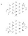
- FIGS. 8A-8Fare example system diagrams of a focused data communications base transmitter array 820 during detection of a new client device 110 .
- the base transmitter array 820is substantially similar to the base transmitter array 120 , and although nineteen antenna elements 821 are shown, it should be understood that more or less antenna elements may be utilized. Additionally, it should be noted that antenna elements 821 are substantially similar to antenna elements 121 .
- the base transmitter array 821When the base transmitter array 821 is operational, it may detect new clients within its service domain and establish time offsets for communication. When a client device 110 is powered on, it attempts to communicate with the base transmitter array 820 . Accordingly, the base transmitter array 820 may tune specific antenna elements 821 to specific directions. For example, in FIG. 8A , antenna elements 9 , 11 and 12 are tuned to a first direction. In FIG. 8B , antenna elements 5 , 15 , and 19 are tuned to a second direction. In FIG. 8C , antenna elements 6 , 14 , and 17 are tuned to a third direction. In FIG. 8D , antenna elements 8 , 9 , and 11 are tuned to a fourth direction. In FIG.
- antenna elements 1 , 5 , and 15are tuned to a fifth direction.
- antenna elements 3 , 6 , and 14are tuned to a sixth direction.
- the tuningmay be accomplished in a soft manner, such as by dedicated circuitry such as the conceptual component 610 describe above.
- each reception lobe of the base transmitter array 820may have a width of 75 degrees, allowing overlap and full coverage around the array. However, it should be noted that any subdivision of 360 degrees may be utilized to form the reception lobes that make up the set of tuned directions.
- FIG. 9shows an example array coverage of a focused data communications system 900 tuned in accordance with the antenna elements 821 in FIGS. 8A-8F .
- the base transmitter array 920which is substantially similar to the base transmitter arrays 120 and 820 , includes a coverage area 930 .
- a plurality of coverage lobes 940include a plurality of overlap areas 941 . Accordingly, a new client device 110 within the coverage area 930 is detected by the base transmitter array 920 .
- the remainder of the antenna elements 821may be provided with information to quickly correct their respective time and phase offsets so that the newly detected client devices 110 receive their focused spatially directed data signal.
- the battery life of the client device 110may be increased as the client device 110 may utilize less power for communication with the base transmitter array 120 / 420 / 820 / 920 . Additionally, the coverage area 930 may be greater than in a conventional communication system for the same power, since focused signals may travel farther, and since the array is able to tune to a particular client device 110 , as opposed to sending signal power out in multiple directions.
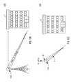
- FIGS. 10A-10Care example diagrams of directivity and location embodiments of a focused communications system 1000 .
- the systemincludes a base transmitter array 1020 , which is substantially similar to the base transmitter arrays 120 , 420 , 820 and 920 .
- conventional data communication arraysinclude antennas directed generally downward, only a client device 110 at ground level G may experience quality data communications. Accordingly, a client device 110 at position T at the top floor of a tall building B, or a client device 110 on an airplane A, may not receive quality data communications.
- high quality signalsmay be provided to client devices 110 at locations G, B, or A.
- FIGS. 10B and 10Cdepict the focused data communication system 1000 in an embodiment that may be utilized for location based services, similar to GPS or navigation services.
- a client device 110 at location Lshown adjacent to building B, may be located using the base transmitter array 1020 .
- the base transmitter array 1020By analyzing the time offsets at each antenna element (not shown) of the base transmitter array 1020 , it can be determined the angle of altitude of location L with respect to the height H of the base transmitter array 1020 .
- an azimuth angle ⁇can be determined by knowledge of the direction of the location L with respect to North in relation to the base transmitter array 1020 .
- location servicesmay be provided to the client device 110 at location L. Effectively, by examining the time delays at the base transmitter array 1020 , the direction of the client may be determined. However, since the base transmitter array 1020 has volumetric size, multiple determined directions may be traced from the edges of the volume to determine where they converge at, which may provide the actual location (direction+distance).
- the methods and devices described abovemay operate at the physical communication layer stack. However, it should be noted that any stack may be utilized to carry out functionality as needed for any of the methods and devices described above.
- the client device described abovemay refer to a cellular phone, PDA, or any other wireless device that may be utilized for data communication.
- the size of the base transmitter arraymay be on the order of the (number of clients) 2.5 , however any size may be utilized.
- client device 110is shown, for purposes of example, as having only a single antenna, it should be noted that client devices may include more than one antenna.
- the base transmitter arraymay be a large set of antennas configured in a three-dimensional (3D) arrangement, where each antenna is capable transmitting one or more data encoded signals, whereby the transmitted signal is the sum of the encoded signals to be transmitted.
- each signalmay be added with a specific time offset that is different for each antenna element.
- One example arrangement to arrange the antenna elements of the base transmitter arrayis to utilize the example of 3D quasi-crystal arrangement.
Landscapes
- Engineering & Computer Science (AREA)
- Computer Networks & Wireless Communication (AREA)
- Signal Processing (AREA)
- Mobile Radio Communication Systems (AREA)
- Variable-Direction Aerials And Aerial Arrays (AREA)
- Radio Transmission System (AREA)
- Chair Legs, Seat Parts, And Backrests (AREA)
- Machines For Laying And Maintaining Railways (AREA)
- Radar Systems Or Details Thereof (AREA)
Abstract
Description
t(n)=p(n)/c, Equation (1)
where c=the speed of light.
time=max(t(n))−t(n). Equation (2)
Reverse Timing=(MaxClientTimeOffset)−ClientTimeOffset, Equation (3)
where the reverse timing is effectively a number between 0 and the ClientTimeOffset for each client, and MaxTimeOffset is the difference in time from the
Claims (12)
Priority Applications (5)
| Application Number | Priority Date | Filing Date | Title |
|---|---|---|---|
| US15/649,187US10523301B2 (en) | 2013-02-22 | 2017-07-13 | Method and apparatus for focused data communications |
| US16/725,215US11265064B2 (en) | 2013-02-22 | 2019-12-23 | Method and apparatus for focused data communications |
| US17/671,212US11784699B2 (en) | 2013-02-22 | 2022-02-14 | Method and apparatus for focused data communications |
| US18/461,124US12052083B2 (en) | 2013-02-22 | 2023-09-05 | Method and apparatus for focused data communications |
| US18/759,777US20240356618A1 (en) | 2013-02-22 | 2024-06-28 | Method and apparatus for focused data communications |
Applications Claiming Priority (4)
| Application Number | Priority Date | Filing Date | Title |
|---|---|---|---|
| US201361768004P | 2013-02-22 | 2013-02-22 | |
| US14/186,344US9351281B2 (en) | 2013-02-22 | 2014-02-21 | Method and apparatus for focused data communications |
| US15/153,361US9736815B2 (en) | 2013-02-22 | 2016-05-12 | Method and apparatus for focused data communications |
| US15/649,187US10523301B2 (en) | 2013-02-22 | 2017-07-13 | Method and apparatus for focused data communications |
Related Parent Applications (1)
| Application Number | Title | Priority Date | Filing Date |
|---|---|---|---|
| US15/153,361ContinuationUS9736815B2 (en) | 2013-02-22 | 2016-05-12 | Method and apparatus for focused data communications |
Related Child Applications (1)
| Application Number | Title | Priority Date | Filing Date |
|---|---|---|---|
| US16/725,215ContinuationUS11265064B2 (en) | 2013-02-22 | 2019-12-23 | Method and apparatus for focused data communications |
Publications (2)
| Publication Number | Publication Date |
|---|---|
| US20170311288A1 US20170311288A1 (en) | 2017-10-26 |
| US10523301B2true US10523301B2 (en) | 2019-12-31 |
Family
ID=51388051
Family Applications (7)
| Application Number | Title | Priority Date | Filing Date |
|---|---|---|---|
| US14/186,344ActiveUS9351281B2 (en) | 2013-02-22 | 2014-02-21 | Method and apparatus for focused data communications |
| US15/153,361ActiveUS9736815B2 (en) | 2013-02-22 | 2016-05-12 | Method and apparatus for focused data communications |
| US15/649,187ActiveUS10523301B2 (en) | 2013-02-22 | 2017-07-13 | Method and apparatus for focused data communications |
| US16/725,215Active2034-03-25US11265064B2 (en) | 2013-02-22 | 2019-12-23 | Method and apparatus for focused data communications |
| US17/671,212ActiveUS11784699B2 (en) | 2013-02-22 | 2022-02-14 | Method and apparatus for focused data communications |
| US18/461,124ActiveUS12052083B2 (en) | 2013-02-22 | 2023-09-05 | Method and apparatus for focused data communications |
| US18/759,777PendingUS20240356618A1 (en) | 2013-02-22 | 2024-06-28 | Method and apparatus for focused data communications |
Family Applications Before (2)
| Application Number | Title | Priority Date | Filing Date |
|---|---|---|---|
| US14/186,344ActiveUS9351281B2 (en) | 2013-02-22 | 2014-02-21 | Method and apparatus for focused data communications |
| US15/153,361ActiveUS9736815B2 (en) | 2013-02-22 | 2016-05-12 | Method and apparatus for focused data communications |
Family Applications After (4)
| Application Number | Title | Priority Date | Filing Date |
|---|---|---|---|
| US16/725,215Active2034-03-25US11265064B2 (en) | 2013-02-22 | 2019-12-23 | Method and apparatus for focused data communications |
| US17/671,212ActiveUS11784699B2 (en) | 2013-02-22 | 2022-02-14 | Method and apparatus for focused data communications |
| US18/461,124ActiveUS12052083B2 (en) | 2013-02-22 | 2023-09-05 | Method and apparatus for focused data communications |
| US18/759,777PendingUS20240356618A1 (en) | 2013-02-22 | 2024-06-28 | Method and apparatus for focused data communications |
Country Status (9)
| Country | Link |
|---|---|
| US (7) | US9351281B2 (en) |
| EP (2) | EP2959601B1 (en) |
| JP (5) | JP6329182B2 (en) |
| KR (3) | KR102072834B1 (en) |
| CN (4) | CN107196692B (en) |
| BR (1) | BR112015020236A2 (en) |
| HK (1) | HK1218593A1 (en) |
| TW (2) | TW201635820A (en) |
| WO (1) | WO2014130787A1 (en) |
Cited By (1)
| Publication number | Priority date | Publication date | Assignee | Title |
|---|---|---|---|---|
| US11265064B2 (en)* | 2013-02-22 | 2022-03-01 | Ossia Inc. | Method and apparatus for focused data communications |
Families Citing this family (223)
| Publication number | Priority date | Publication date | Assignee | Title |
|---|---|---|---|---|
| US9124125B2 (en) | 2013-05-10 | 2015-09-01 | Energous Corporation | Wireless power transmission with selective range |
| US9853692B1 (en) | 2014-05-23 | 2017-12-26 | Energous Corporation | Systems and methods for wireless power transmission |
| US9368020B1 (en) | 2013-05-10 | 2016-06-14 | Energous Corporation | Off-premises alert system and method for wireless power receivers in a wireless power network |
| US9900057B2 (en) | 2012-07-06 | 2018-02-20 | Energous Corporation | Systems and methods for assigning groups of antenas of a wireless power transmitter to different wireless power receivers, and determining effective phases to use for wirelessly transmitting power using the assigned groups of antennas |
| US9871398B1 (en) | 2013-07-01 | 2018-01-16 | Energous Corporation | Hybrid charging method for wireless power transmission based on pocket-forming |
| US10218227B2 (en) | 2014-05-07 | 2019-02-26 | Energous Corporation | Compact PIFA antenna |
| US10224982B1 (en) | 2013-07-11 | 2019-03-05 | Energous Corporation | Wireless power transmitters for transmitting wireless power and tracking whether wireless power receivers are within authorized locations |
| US9867062B1 (en) | 2014-07-21 | 2018-01-09 | Energous Corporation | System and methods for using a remote server to authorize a receiving device that has requested wireless power and to determine whether another receiving device should request wireless power in a wireless power transmission system |
| US10199835B2 (en) | 2015-12-29 | 2019-02-05 | Energous Corporation | Radar motion detection using stepped frequency in wireless power transmission system |
| US10965164B2 (en) | 2012-07-06 | 2021-03-30 | Energous Corporation | Systems and methods of wirelessly delivering power to a receiver device |
| US9893555B1 (en) | 2013-10-10 | 2018-02-13 | Energous Corporation | Wireless charging of tools using a toolbox transmitter |
| US10050462B1 (en) | 2013-08-06 | 2018-08-14 | Energous Corporation | Social power sharing for mobile devices based on pocket-forming |
| US9787103B1 (en) | 2013-08-06 | 2017-10-10 | Energous Corporation | Systems and methods for wirelessly delivering power to electronic devices that are unable to communicate with a transmitter |
| US10090886B1 (en) | 2014-07-14 | 2018-10-02 | Energous Corporation | System and method for enabling automatic charging schedules in a wireless power network to one or more devices |
| US11502551B2 (en) | 2012-07-06 | 2022-11-15 | Energous Corporation | Wirelessly charging multiple wireless-power receivers using different subsets of an antenna array to focus energy at different locations |
| US10193396B1 (en) | 2014-05-07 | 2019-01-29 | Energous Corporation | Cluster management of transmitters in a wireless power transmission system |
| US10211674B1 (en) | 2013-06-12 | 2019-02-19 | Energous Corporation | Wireless charging using selected reflectors |
| US9887584B1 (en) | 2014-08-21 | 2018-02-06 | Energous Corporation | Systems and methods for a configuration web service to provide configuration of a wireless power transmitter within a wireless power transmission system |
| US9793758B2 (en) | 2014-05-23 | 2017-10-17 | Energous Corporation | Enhanced transmitter using frequency control for wireless power transmission |
| US9882427B2 (en) | 2013-05-10 | 2018-01-30 | Energous Corporation | Wireless power delivery using a base station to control operations of a plurality of wireless power transmitters |
| US10141791B2 (en) | 2014-05-07 | 2018-11-27 | Energous Corporation | Systems and methods for controlling communications during wireless transmission of power using application programming interfaces |
| US10291055B1 (en) | 2014-12-29 | 2019-05-14 | Energous Corporation | Systems and methods for controlling far-field wireless power transmission based on battery power levels of a receiving device |
| US10008889B2 (en) | 2014-08-21 | 2018-06-26 | Energous Corporation | Method for automatically testing the operational status of a wireless power receiver in a wireless power transmission system |
| US10256657B2 (en) | 2015-12-24 | 2019-04-09 | Energous Corporation | Antenna having coaxial structure for near field wireless power charging |
| US10263432B1 (en) | 2013-06-25 | 2019-04-16 | Energous Corporation | Multi-mode transmitter with an antenna array for delivering wireless power and providing Wi-Fi access |
| US9954374B1 (en) | 2014-05-23 | 2018-04-24 | Energous Corporation | System and method for self-system analysis for detecting a fault in a wireless power transmission Network |
| US9838083B2 (en) | 2014-07-21 | 2017-12-05 | Energous Corporation | Systems and methods for communication with remote management systems |
| US9973021B2 (en) | 2012-07-06 | 2018-05-15 | Energous Corporation | Receivers for wireless power transmission |
| US9876380B1 (en) | 2013-09-13 | 2018-01-23 | Energous Corporation | Secured wireless power distribution system |
| US20140008993A1 (en) | 2012-07-06 | 2014-01-09 | DvineWave Inc. | Methodology for pocket-forming |
| US9876379B1 (en) | 2013-07-11 | 2018-01-23 | Energous Corporation | Wireless charging and powering of electronic devices in a vehicle |
| US9843213B2 (en) | 2013-08-06 | 2017-12-12 | Energous Corporation | Social power sharing for mobile devices based on pocket-forming |
| US9859797B1 (en) | 2014-05-07 | 2018-01-02 | Energous Corporation | Synchronous rectifier design for wireless power receiver |
| US9843201B1 (en) | 2012-07-06 | 2017-12-12 | Energous Corporation | Wireless power transmitter that selects antenna sets for transmitting wireless power to a receiver based on location of the receiver, and methods of use thereof |
| US9991741B1 (en) | 2014-07-14 | 2018-06-05 | Energous Corporation | System for tracking and reporting status and usage information in a wireless power management system |
| US9450449B1 (en) | 2012-07-06 | 2016-09-20 | Energous Corporation | Antenna arrangement for pocket-forming |
| US9143000B2 (en) | 2012-07-06 | 2015-09-22 | Energous Corporation | Portable wireless charging pad |
| US9831718B2 (en) | 2013-07-25 | 2017-11-28 | Energous Corporation | TV with integrated wireless power transmitter |
| US9824815B2 (en) | 2013-05-10 | 2017-11-21 | Energous Corporation | Wireless charging and powering of healthcare gadgets and sensors |
| US10312715B2 (en) | 2015-09-16 | 2019-06-04 | Energous Corporation | Systems and methods for wireless power charging |
| US9847679B2 (en) | 2014-05-07 | 2017-12-19 | Energous Corporation | System and method for controlling communication between wireless power transmitter managers |
| US9882430B1 (en) | 2014-05-07 | 2018-01-30 | Energous Corporation | Cluster management of transmitters in a wireless power transmission system |
| US10992187B2 (en) | 2012-07-06 | 2021-04-27 | Energous Corporation | System and methods of using electromagnetic waves to wirelessly deliver power to electronic devices |
| US10199849B1 (en) | 2014-08-21 | 2019-02-05 | Energous Corporation | Method for automatically testing the operational status of a wireless power receiver in a wireless power transmission system |
| US9912199B2 (en) | 2012-07-06 | 2018-03-06 | Energous Corporation | Receivers for wireless power transmission |
| US10090699B1 (en) | 2013-11-01 | 2018-10-02 | Energous Corporation | Wireless powered house |
| US10230266B1 (en) | 2014-02-06 | 2019-03-12 | Energous Corporation | Wireless power receivers that communicate status data indicating wireless power transmission effectiveness with a transmitter using a built-in communications component of a mobile device, and methods of use thereof |
| US9923386B1 (en) | 2012-07-06 | 2018-03-20 | Energous Corporation | Systems and methods for wireless power transmission by modifying a number of antenna elements used to transmit power waves to a receiver |
| US10223717B1 (en) | 2014-05-23 | 2019-03-05 | Energous Corporation | Systems and methods for payment-based authorization of wireless power transmission service |
| US9876648B2 (en) | 2014-08-21 | 2018-01-23 | Energous Corporation | System and method to control a wireless power transmission system by configuration of wireless power transmission control parameters |
| US9893554B2 (en) | 2014-07-14 | 2018-02-13 | Energous Corporation | System and method for providing health safety in a wireless power transmission system |
| US20150326070A1 (en) | 2014-05-07 | 2015-11-12 | Energous Corporation | Methods and Systems for Maximum Power Point Transfer in Receivers |
| US10211680B2 (en) | 2013-07-19 | 2019-02-19 | Energous Corporation | Method for 3 dimensional pocket-forming |
| US10224758B2 (en) | 2013-05-10 | 2019-03-05 | Energous Corporation | Wireless powering of electronic devices with selective delivery range |
| US9438045B1 (en) | 2013-05-10 | 2016-09-06 | Energous Corporation | Methods and systems for maximum power point transfer in receivers |
| US10243414B1 (en) | 2014-05-07 | 2019-03-26 | Energous Corporation | Wearable device with wireless power and payload receiver |
| US9899873B2 (en) | 2014-05-23 | 2018-02-20 | Energous Corporation | System and method for generating a power receiver identifier in a wireless power network |
| US9847677B1 (en) | 2013-10-10 | 2017-12-19 | Energous Corporation | Wireless charging and powering of healthcare gadgets and sensors |
| US10148097B1 (en) | 2013-11-08 | 2018-12-04 | Energous Corporation | Systems and methods for using a predetermined number of communication channels of a wireless power transmitter to communicate with different wireless power receivers |
| US10211682B2 (en) | 2014-05-07 | 2019-02-19 | Energous Corporation | Systems and methods for controlling operation of a transmitter of a wireless power network based on user instructions received from an authenticated computing device powered or charged by a receiver of the wireless power network |
| US10075008B1 (en) | 2014-07-14 | 2018-09-11 | Energous Corporation | Systems and methods for manually adjusting when receiving electronic devices are scheduled to receive wirelessly delivered power from a wireless power transmitter in a wireless power network |
| US9941747B2 (en) | 2014-07-14 | 2018-04-10 | Energous Corporation | System and method for manually selecting and deselecting devices to charge in a wireless power network |
| US9941707B1 (en) | 2013-07-19 | 2018-04-10 | Energous Corporation | Home base station for multiple room coverage with multiple transmitters |
| US9948135B2 (en) | 2015-09-22 | 2018-04-17 | Energous Corporation | Systems and methods for identifying sensitive objects in a wireless charging transmission field |
| US9906065B2 (en) | 2012-07-06 | 2018-02-27 | Energous Corporation | Systems and methods of transmitting power transmission waves based on signals received at first and second subsets of a transmitter's antenna array |
| US9252628B2 (en) | 2013-05-10 | 2016-02-02 | Energous Corporation | Laptop computer as a transmitter for wireless charging |
| US10063064B1 (en) | 2014-05-23 | 2018-08-28 | Energous Corporation | System and method for generating a power receiver identifier in a wireless power network |
| US9939864B1 (en) | 2014-08-21 | 2018-04-10 | Energous Corporation | System and method to control a wireless power transmission system by configuration of wireless power transmission control parameters |
| US10186913B2 (en) | 2012-07-06 | 2019-01-22 | Energous Corporation | System and methods for pocket-forming based on constructive and destructive interferences to power one or more wireless power receivers using a wireless power transmitter including a plurality of antennas |
| US9859756B2 (en) | 2012-07-06 | 2018-01-02 | Energous Corporation | Transmittersand methods for adjusting wireless power transmission based on information from receivers |
| US10038337B1 (en) | 2013-09-16 | 2018-07-31 | Energous Corporation | Wireless power supply for rescue devices |
| US9853458B1 (en) | 2014-05-07 | 2017-12-26 | Energous Corporation | Systems and methods for device and power receiver pairing |
| US10270261B2 (en) | 2015-09-16 | 2019-04-23 | Energous Corporation | Systems and methods of object detection in wireless power charging systems |
| US10063106B2 (en) | 2014-05-23 | 2018-08-28 | Energous Corporation | System and method for a self-system analysis in a wireless power transmission network |
| US10206185B2 (en) | 2013-05-10 | 2019-02-12 | Energous Corporation | System and methods for wireless power transmission to an electronic device in accordance with user-defined restrictions |
| US10205239B1 (en) | 2014-05-07 | 2019-02-12 | Energous Corporation | Compact PIFA antenna |
| US9806564B2 (en) | 2014-05-07 | 2017-10-31 | Energous Corporation | Integrated rectifier and boost converter for wireless power transmission |
| US9859757B1 (en) | 2013-07-25 | 2018-01-02 | Energous Corporation | Antenna tile arrangements in electronic device enclosures |
| US10141768B2 (en) | 2013-06-03 | 2018-11-27 | Energous Corporation | Systems and methods for maximizing wireless power transfer efficiency by instructing a user to change a receiver device's position |
| US9966765B1 (en) | 2013-06-25 | 2018-05-08 | Energous Corporation | Multi-mode transmitter |
| US9825674B1 (en) | 2014-05-23 | 2017-11-21 | Energous Corporation | Enhanced transmitter that selects configurations of antenna elements for performing wireless power transmission and receiving functions |
| US9893768B2 (en) | 2012-07-06 | 2018-02-13 | Energous Corporation | Methodology for multiple pocket-forming |
| US10103582B2 (en) | 2012-07-06 | 2018-10-16 | Energous Corporation | Transmitters for wireless power transmission |
| US9130397B2 (en) | 2013-05-10 | 2015-09-08 | Energous Corporation | Wireless charging and powering of electronic devices in a vehicle |
| US10291066B1 (en) | 2014-05-07 | 2019-05-14 | Energous Corporation | Power transmission control systems and methods |
| US10381880B2 (en) | 2014-07-21 | 2019-08-13 | Energous Corporation | Integrated antenna structure arrays for wireless power transmission |
| US9941754B2 (en) | 2012-07-06 | 2018-04-10 | Energous Corporation | Wireless power transmission with selective range |
| US9891669B2 (en) | 2014-08-21 | 2018-02-13 | Energous Corporation | Systems and methods for a configuration web service to provide configuration of a wireless power transmitter within a wireless power transmission system |
| US9899861B1 (en) | 2013-10-10 | 2018-02-20 | Energous Corporation | Wireless charging methods and systems for game controllers, based on pocket-forming |
| US9876394B1 (en) | 2014-05-07 | 2018-01-23 | Energous Corporation | Boost-charger-boost system for enhanced power delivery |
| US10124754B1 (en) | 2013-07-19 | 2018-11-13 | Energous Corporation | Wireless charging and powering of electronic sensors in a vehicle |
| US10128693B2 (en) | 2014-07-14 | 2018-11-13 | Energous Corporation | System and method for providing health safety in a wireless power transmission system |
| US9887739B2 (en) | 2012-07-06 | 2018-02-06 | Energous Corporation | Systems and methods for wireless power transmission by comparing voltage levels associated with power waves transmitted by antennas of a plurality of antennas of a transmitter to determine appropriate phase adjustments for the power waves |
| US10128699B2 (en) | 2014-07-14 | 2018-11-13 | Energous Corporation | Systems and methods of providing wireless power using receiver device sensor inputs |
| US10992185B2 (en) | 2012-07-06 | 2021-04-27 | Energous Corporation | Systems and methods of using electromagnetic waves to wirelessly deliver power to game controllers |
| US9812890B1 (en) | 2013-07-11 | 2017-11-07 | Energous Corporation | Portable wireless charging pad |
| US12057715B2 (en) | 2012-07-06 | 2024-08-06 | Energous Corporation | Systems and methods of wirelessly delivering power to a wireless-power receiver device in response to a change of orientation of the wireless-power receiver device |
| US10063105B2 (en) | 2013-07-11 | 2018-08-28 | Energous Corporation | Proximity transmitters for wireless power charging systems |
| US10439448B2 (en) | 2014-08-21 | 2019-10-08 | Energous Corporation | Systems and methods for automatically testing the communication between wireless power transmitter and wireless power receiver |
| EP2984901A4 (en)* | 2013-04-07 | 2016-12-14 | Ziva Corp | Distributed co-operating nodes using time reversal |
| US9819230B2 (en) | 2014-05-07 | 2017-11-14 | Energous Corporation | Enhanced receiver for wireless power transmission |
| US9537357B2 (en) | 2013-05-10 | 2017-01-03 | Energous Corporation | Wireless sound charging methods and systems for game controllers, based on pocket-forming |
| US9419443B2 (en) | 2013-05-10 | 2016-08-16 | Energous Corporation | Transducer sound arrangement for pocket-forming |
| US9843763B2 (en) | 2013-05-10 | 2017-12-12 | Energous Corporation | TV system with wireless power transmitter |
| US9538382B2 (en) | 2013-05-10 | 2017-01-03 | Energous Corporation | System and method for smart registration of wireless power receivers in a wireless power network |
| US9866279B2 (en) | 2013-05-10 | 2018-01-09 | Energous Corporation | Systems and methods for selecting which power transmitter should deliver wireless power to a receiving device in a wireless power delivery network |
| US10103552B1 (en) | 2013-06-03 | 2018-10-16 | Energous Corporation | Protocols for authenticated wireless power transmission |
| US10003211B1 (en) | 2013-06-17 | 2018-06-19 | Energous Corporation | Battery life of portable electronic devices |
| US9521926B1 (en) | 2013-06-24 | 2016-12-20 | Energous Corporation | Wireless electrical temperature regulator for food and beverages |
| US10021523B2 (en) | 2013-07-11 | 2018-07-10 | Energous Corporation | Proximity transmitters for wireless power charging systems |
| US9979440B1 (en) | 2013-07-25 | 2018-05-22 | Energous Corporation | Antenna tile arrangements configured to operate as one functional unit |
| US10075017B2 (en) | 2014-02-06 | 2018-09-11 | Energous Corporation | External or internal wireless power receiver with spaced-apart antenna elements for charging or powering mobile devices using wirelessly delivered power |
| US9935482B1 (en) | 2014-02-06 | 2018-04-03 | Energous Corporation | Wireless power transmitters that transmit at determined times based on power availability and consumption at a receiving mobile device |
| US10158257B2 (en) | 2014-05-01 | 2018-12-18 | Energous Corporation | System and methods for using sound waves to wirelessly deliver power to electronic devices |
| US9966784B2 (en) | 2014-06-03 | 2018-05-08 | Energous Corporation | Systems and methods for extending battery life of portable electronic devices charged by sound |
| US9973008B1 (en) | 2014-05-07 | 2018-05-15 | Energous Corporation | Wireless power receiver with boost converters directly coupled to a storage element |
| US10153653B1 (en) | 2014-05-07 | 2018-12-11 | Energous Corporation | Systems and methods for using application programming interfaces to control communications between a transmitter and a receiver |
| US10170917B1 (en) | 2014-05-07 | 2019-01-01 | Energous Corporation | Systems and methods for managing and controlling a wireless power network by establishing time intervals during which receivers communicate with a transmitter |
| US10153645B1 (en) | 2014-05-07 | 2018-12-11 | Energous Corporation | Systems and methods for designating a master power transmitter in a cluster of wireless power transmitters |
| US9800172B1 (en) | 2014-05-07 | 2017-10-24 | Energous Corporation | Integrated rectifier and boost converter for boosting voltage received from wireless power transmission waves |
| US9876536B1 (en) | 2014-05-23 | 2018-01-23 | Energous Corporation | Systems and methods for assigning groups of antennas to transmit wireless power to different wireless power receivers |
| US9871301B2 (en) | 2014-07-21 | 2018-01-16 | Energous Corporation | Integrated miniature PIFA with artificial magnetic conductor metamaterials |
| US10116143B1 (en) | 2014-07-21 | 2018-10-30 | Energous Corporation | Integrated antenna arrays for wireless power transmission |
| US10068703B1 (en) | 2014-07-21 | 2018-09-04 | Energous Corporation | Integrated miniature PIFA with artificial magnetic conductor metamaterials |
| US9917477B1 (en) | 2014-08-21 | 2018-03-13 | Energous Corporation | Systems and methods for automatically testing the communication between power transmitter and wireless receiver |
| US9965009B1 (en) | 2014-08-21 | 2018-05-08 | Energous Corporation | Systems and methods for assigning a power receiver to individual power transmitters based on location of the power receiver |
| US10122415B2 (en) | 2014-12-27 | 2018-11-06 | Energous Corporation | Systems and methods for assigning a set of antennas of a wireless power transmitter to a wireless power receiver based on a location of the wireless power receiver |
| US9893535B2 (en) | 2015-02-13 | 2018-02-13 | Energous Corporation | Systems and methods for determining optimal charging positions to maximize efficiency of power received from wirelessly delivered sound wave energy |
| US9906275B2 (en) | 2015-09-15 | 2018-02-27 | Energous Corporation | Identifying receivers in a wireless charging transmission field |
| US10523033B2 (en) | 2015-09-15 | 2019-12-31 | Energous Corporation | Receiver devices configured to determine location within a transmission field |
| US12283828B2 (en) | 2015-09-15 | 2025-04-22 | Energous Corporation | Receiver devices configured to determine location within a transmission field |
| US10199850B2 (en) | 2015-09-16 | 2019-02-05 | Energous Corporation | Systems and methods for wirelessly transmitting power from a transmitter to a receiver by determining refined locations of the receiver in a segmented transmission field associated with the transmitter |
| US11710321B2 (en) | 2015-09-16 | 2023-07-25 | Energous Corporation | Systems and methods of object detection in wireless power charging systems |
| US10778041B2 (en) | 2015-09-16 | 2020-09-15 | Energous Corporation | Systems and methods for generating power waves in a wireless power transmission system |
| US10008875B1 (en) | 2015-09-16 | 2018-06-26 | Energous Corporation | Wireless power transmitter configured to transmit power waves to a predicted location of a moving wireless power receiver |
| US10158259B1 (en) | 2015-09-16 | 2018-12-18 | Energous Corporation | Systems and methods for identifying receivers in a transmission field by transmitting exploratory power waves towards different segments of a transmission field |
| US9893538B1 (en) | 2015-09-16 | 2018-02-13 | Energous Corporation | Systems and methods of object detection in wireless power charging systems |
| US10211685B2 (en) | 2015-09-16 | 2019-02-19 | Energous Corporation | Systems and methods for real or near real time wireless communications between a wireless power transmitter and a wireless power receiver |
| US9871387B1 (en) | 2015-09-16 | 2018-01-16 | Energous Corporation | Systems and methods of object detection using one or more video cameras in wireless power charging systems |
| US10186893B2 (en) | 2015-09-16 | 2019-01-22 | Energous Corporation | Systems and methods for real time or near real time wireless communications between a wireless power transmitter and a wireless power receiver |
| US9941752B2 (en) | 2015-09-16 | 2018-04-10 | Energous Corporation | Systems and methods of object detection in wireless power charging systems |
| US10033222B1 (en) | 2015-09-22 | 2018-07-24 | Energous Corporation | Systems and methods for determining and generating a waveform for wireless power transmission waves |
| US10020678B1 (en) | 2015-09-22 | 2018-07-10 | Energous Corporation | Systems and methods for selecting antennas to generate and transmit power transmission waves |
| US10153660B1 (en) | 2015-09-22 | 2018-12-11 | Energous Corporation | Systems and methods for preconfiguring sensor data for wireless charging systems |
| US10128686B1 (en) | 2015-09-22 | 2018-11-13 | Energous Corporation | Systems and methods for identifying receiver locations using sensor technologies |
| US10135294B1 (en) | 2015-09-22 | 2018-11-20 | Energous Corporation | Systems and methods for preconfiguring transmission devices for power wave transmissions based on location data of one or more receivers |
| US10050470B1 (en) | 2015-09-22 | 2018-08-14 | Energous Corporation | Wireless power transmission device having antennas oriented in three dimensions |
| US10027168B2 (en) | 2015-09-22 | 2018-07-17 | Energous Corporation | Systems and methods for generating and transmitting wireless power transmission waves using antennas having a spacing that is selected by the transmitter |
| US10135295B2 (en) | 2015-09-22 | 2018-11-20 | Energous Corporation | Systems and methods for nullifying energy levels for wireless power transmission waves |
| US10333332B1 (en) | 2015-10-13 | 2019-06-25 | Energous Corporation | Cross-polarized dipole antenna |
| US10734717B2 (en) | 2015-10-13 | 2020-08-04 | Energous Corporation | 3D ceramic mold antenna |
| JP2018536372A (en) | 2015-10-15 | 2018-12-06 | オシア,インク. | Concentration method of pulsed transmission in multipath wireless power supply environment |
| US9899744B1 (en) | 2015-10-28 | 2018-02-20 | Energous Corporation | Antenna for wireless charging systems |
| US9853485B2 (en) | 2015-10-28 | 2017-12-26 | Energous Corporation | Antenna for wireless charging systems |
| US10063108B1 (en) | 2015-11-02 | 2018-08-28 | Energous Corporation | Stamped three-dimensional antenna |
| US10135112B1 (en) | 2015-11-02 | 2018-11-20 | Energous Corporation | 3D antenna mount |
| US10027180B1 (en) | 2015-11-02 | 2018-07-17 | Energous Corporation | 3D triple linear antenna that acts as heat sink |
| US10263465B2 (en) | 2015-12-17 | 2019-04-16 | Witricity Corporation | Radiative wireless power transmission |
| US10256677B2 (en) | 2016-12-12 | 2019-04-09 | Energous Corporation | Near-field RF charging pad with adaptive loading to efficiently charge an electronic device at any position on the pad |
| US10027159B2 (en) | 2015-12-24 | 2018-07-17 | Energous Corporation | Antenna for transmitting wireless power signals |
| US10038332B1 (en) | 2015-12-24 | 2018-07-31 | Energous Corporation | Systems and methods of wireless power charging through multiple receiving devices |
| US10079515B2 (en) | 2016-12-12 | 2018-09-18 | Energous Corporation | Near-field RF charging pad with multi-band antenna element with adaptive loading to efficiently charge an electronic device at any position on the pad |
| US10116162B2 (en) | 2015-12-24 | 2018-10-30 | Energous Corporation | Near field transmitters with harmonic filters for wireless power charging |
| US10320446B2 (en) | 2015-12-24 | 2019-06-11 | Energous Corporation | Miniaturized highly-efficient designs for near-field power transfer system |
| US11863001B2 (en) | 2015-12-24 | 2024-01-02 | Energous Corporation | Near-field antenna for wireless power transmission with antenna elements that follow meandering patterns |
| US10008886B2 (en) | 2015-12-29 | 2018-06-26 | Energous Corporation | Modular antennas with heat sinks in wireless power transmission systems |
| US10923954B2 (en) | 2016-11-03 | 2021-02-16 | Energous Corporation | Wireless power receiver with a synchronous rectifier |
| KR102185600B1 (en) | 2016-12-12 | 2020-12-03 | 에너저스 코포레이션 | A method of selectively activating antenna zones of a near field charging pad to maximize transmitted wireless power |
| US10680319B2 (en) | 2017-01-06 | 2020-06-09 | Energous Corporation | Devices and methods for reducing mutual coupling effects in wireless power transmission systems |
| US10389161B2 (en) | 2017-03-15 | 2019-08-20 | Energous Corporation | Surface mount dielectric antennas for wireless power transmitters |
| US10439442B2 (en) | 2017-01-24 | 2019-10-08 | Energous Corporation | Microstrip antennas for wireless power transmitters |
| US11011942B2 (en) | 2017-03-30 | 2021-05-18 | Energous Corporation | Flat antennas having two or more resonant frequencies for use in wireless power transmission systems |
| US10511097B2 (en) | 2017-05-12 | 2019-12-17 | Energous Corporation | Near-field antennas for accumulating energy at a near-field distance with minimal far-field gain |
| US12074460B2 (en) | 2017-05-16 | 2024-08-27 | Wireless Electrical Grid Lan, Wigl Inc. | Rechargeable wireless power bank and method of using |
| US11462949B2 (en) | 2017-05-16 | 2022-10-04 | Wireless electrical Grid LAN, WiGL Inc | Wireless charging method and system |
| US12074452B2 (en) | 2017-05-16 | 2024-08-27 | Wireless Electrical Grid Lan, Wigl Inc. | Networked wireless charging system |
| US10848853B2 (en) | 2017-06-23 | 2020-11-24 | Energous Corporation | Systems, methods, and devices for utilizing a wire of a sound-producing device as an antenna for receipt of wirelessly delivered power |
| US10122219B1 (en) | 2017-10-10 | 2018-11-06 | Energous Corporation | Systems, methods, and devices for using a battery as a antenna for receiving wirelessly delivered power from radio frequency power waves |
| US11342798B2 (en) | 2017-10-30 | 2022-05-24 | Energous Corporation | Systems and methods for managing coexistence of wireless-power signals and data signals operating in a same frequency band |
| CN117791901A (en)* | 2017-11-08 | 2024-03-29 | 欧希亚有限公司 | Wireless power transmission system and method of operating the same |
| CN111758204B (en)* | 2017-12-22 | 2021-10-19 | 欧希亚有限公司 | Transmission Path Identification Based on Propagation Channel Diversity |
| US10418861B2 (en) | 2017-12-22 | 2019-09-17 | Ossia Inc. | Transmission path identification based on propagation channel diversity |
| US10615647B2 (en) | 2018-02-02 | 2020-04-07 | Energous Corporation | Systems and methods for detecting wireless power receivers and other objects at a near-field charging pad |
| US11159057B2 (en) | 2018-03-14 | 2021-10-26 | Energous Corporation | Loop antennas with selectively-activated feeds to control propagation patterns of wireless power signals |
| US11515732B2 (en) | 2018-06-25 | 2022-11-29 | Energous Corporation | Power wave transmission techniques to focus wirelessly delivered power at a receiving device |
| US11437735B2 (en) | 2018-11-14 | 2022-09-06 | Energous Corporation | Systems for receiving electromagnetic energy using antennas that are minimally affected by the presence of the human body |
| JP7247541B2 (en)* | 2018-11-22 | 2023-03-29 | 株式会社三洋物産 | game machine |
| JP7247540B2 (en)* | 2018-11-22 | 2023-03-29 | 株式会社三洋物産 | game machine |
| JP2020103414A (en)* | 2018-12-26 | 2020-07-09 | 株式会社三洋物産 | Game machine |
| JP2020103417A (en)* | 2018-12-26 | 2020-07-09 | 株式会社三洋物産 | Game machine |
| JP2020103418A (en)* | 2018-12-26 | 2020-07-09 | 株式会社三洋物産 | Game machine |
| US11539243B2 (en) | 2019-01-28 | 2022-12-27 | Energous Corporation | Systems and methods for miniaturized antenna for wireless power transmissions |
| EP3921945A1 (en) | 2019-02-06 | 2021-12-15 | Energous Corporation | Systems and methods of estimating optimal phases to use for individual antennas in an antenna array |
| JP2020130466A (en)* | 2019-02-15 | 2020-08-31 | 株式会社三洋物産 | Game machine |
| JP7234741B2 (en)* | 2019-03-28 | 2023-03-08 | 株式会社三洋物産 | game machine |
| JP7234740B2 (en)* | 2019-03-28 | 2023-03-08 | 株式会社三洋物産 | game machine |
| US12155231B2 (en) | 2019-04-09 | 2024-11-26 | Energous Corporation | Asymmetric spiral antennas for wireless power transmission and reception |
| JP7234761B2 (en)* | 2019-04-11 | 2023-03-08 | 株式会社三洋物産 | game machine |
| JP7234760B2 (en)* | 2019-04-11 | 2023-03-08 | 株式会社三洋物産 | game machine |
| US11381118B2 (en) | 2019-09-20 | 2022-07-05 | Energous Corporation | Systems and methods for machine learning based foreign object detection for wireless power transmission |
| WO2021055899A1 (en) | 2019-09-20 | 2021-03-25 | Energous Corporation | Systems and methods of protecting wireless power receivers using multiple rectifiers and establishing in-band communications using multiple rectifiers |
| WO2021055901A1 (en) | 2019-09-20 | 2021-03-25 | Energous Corporation | Asymmetric spiral antennas with parasitic elements for wireless power transmission |
| CN114731061A (en) | 2019-09-20 | 2022-07-08 | 艾诺格思公司 | Classifying and detecting foreign objects using a power amplifier controller integrated circuit in a wireless power transmission system |
| WO2021055898A1 (en) | 2019-09-20 | 2021-03-25 | Energous Corporation | Systems and methods for machine learning based foreign object detection for wireless power transmission |
| US11355966B2 (en) | 2019-12-13 | 2022-06-07 | Energous Corporation | Charging pad with guiding contours to align an electronic device on the charging pad and efficiently transfer near-field radio-frequency energy to the electronic device |
| US10985617B1 (en) | 2019-12-31 | 2021-04-20 | Energous Corporation | System for wirelessly transmitting energy at a near-field distance without using beam-forming control |
| JP2021133198A (en)* | 2020-02-28 | 2021-09-13 | 株式会社三洋物産 | Pachinko machine |
| JP2021133199A (en)* | 2020-02-28 | 2021-09-13 | 株式会社三洋物産 | Pachinko machine |
| JP2021133200A (en)* | 2020-02-28 | 2021-09-13 | 株式会社三洋物産 | Pachinko machine |
| US11799324B2 (en) | 2020-04-13 | 2023-10-24 | Energous Corporation | Wireless-power transmitting device for creating a uniform near-field charging area |
| JP2021186294A (en)* | 2020-05-29 | 2021-12-13 | 株式会社三洋物産 | Game machine |
| US12042043B2 (en) | 2020-06-11 | 2024-07-23 | Kohler Co. | Temperature tracking mirror |
| JP2022012090A (en)* | 2020-06-30 | 2022-01-17 | 株式会社三洋物産 | Game machine |
| JP2022012089A (en)* | 2020-06-30 | 2022-01-17 | 株式会社三洋物産 | Game machine |
| JP2022012088A (en)* | 2020-06-30 | 2022-01-17 | 株式会社三洋物産 | Game machine |
| US11469629B2 (en) | 2020-08-12 | 2022-10-11 | Energous Corporation | Systems and methods for secure wireless transmission of power using unidirectional communication signals from a wireless-power-receiving device |
| US12306285B2 (en) | 2020-12-01 | 2025-05-20 | Energous Corporation | Systems and methods for using one or more sensors to detect and classify objects in a keep-out zone of a wireless-power transmission field, and antennas with integrated sensor arrangements |
| US11916398B2 (en) | 2021-12-29 | 2024-02-27 | Energous Corporation | Small form-factor devices with integrated and modular harvesting receivers, and shelving-mounted wireless-power transmitters for use therewith |
| JP2023063369A (en)* | 2022-01-07 | 2023-05-09 | 株式会社三洋物産 | game machine |
| JP2023060270A (en)* | 2022-04-01 | 2023-04-27 | 株式会社三洋物産 | game machine |
| JP2023060269A (en)* | 2022-04-01 | 2023-04-27 | 株式会社三洋物産 | game machine |
| US12142939B2 (en) | 2022-05-13 | 2024-11-12 | Energous Corporation | Integrated wireless-power-transmission platform designed to operate in multiple bands, and multi-band antennas for use therewith |
| CN117556246B (en)* | 2024-01-09 | 2024-03-19 | 电信科学技术第五研究所有限公司 | Method for separating single wave signal from carrier mixed signal |
Citations (36)
| Publication number | Priority date | Publication date | Assignee | Title |
|---|---|---|---|---|
| US3314067A (en)* | 1963-12-31 | 1967-04-11 | Ibm | Re-directive antenna array and related communications system |
| JPH06303172A (en) | 1993-02-05 | 1994-10-28 | Philips Electron Nv | Wireless systems and base stations and mobile stations |
| JPH1070502A (en) | 1996-08-28 | 1998-03-10 | Matsushita Electric Ind Co Ltd | Directivity control antenna device |
| US6167272A (en) | 1996-11-25 | 2000-12-26 | Alcatel | Test transmitter, method and computer for testing a cellular mobile radio network |
| US20020085627A1 (en) | 2000-08-07 | 2002-07-04 | Saed Younis | Method and apparatus for base station and mobile station time calibration |
| US20030117320A1 (en) | 2001-12-26 | 2003-06-26 | Eung-Bae Kim | Apparatus and method for tracking location of mobile station |
| US20040023649A1 (en) | 2000-08-08 | 2004-02-05 | Torsten Bing | Method for conducting data communications with subscriber stations, and radio communications network for implementing said method |
| US20040203905A1 (en) | 2002-06-28 | 2004-10-14 | Interdigital Technology Corporation | Method and system for determining the speed and distance of a mobile unit |
| CN1545770A (en) | 2001-05-31 | 2004-11-10 | ���ŵ���ǿ���ɷ�����˾ | Communication device with smart antenna using a quality-indication signal |
| JP2005140639A (en) | 2003-11-06 | 2005-06-02 | Mitsubishi Electric Corp | Distributed aperture radar system |
| JP2005159504A (en) | 2003-11-21 | 2005-06-16 | Hitachi Kokusai Electric Inc | Base station equipment |
| JP2006166321A (en) | 2004-12-10 | 2006-06-22 | Nec Saitama Ltd | Mobile communication system, mobile terminal, and mobile communication method |
| JP2006246633A (en) | 2005-03-03 | 2006-09-14 | Sony Corp | System, device and method for supplying power, power-receiving device/method, recording medium and program |
| US20070037528A1 (en) | 2005-08-12 | 2007-02-15 | Chinh Doan | Wireless communication device using adaptive beamforming |
| US20070140177A1 (en) | 2003-11-25 | 2007-06-21 | Lilin Li | Method and apparatus for implementing beam forming in cdma communication system |
| WO2007084717A2 (en) | 2006-01-18 | 2007-07-26 | Nigel Power Llc. | Method and apparatus for delivering energy to an electrical or electronic device via a wireless link |
| US7288918B2 (en) | 2004-03-02 | 2007-10-30 | Distefano Michael Vincent | Wireless battery charger via carrier frequency signal |
| US20080214128A1 (en) | 2005-06-24 | 2008-09-04 | Samsung Electronics Co., Ltd. | Diversity Transmission Method and Transmitter of a Base Station Using the Same in a Mobile Commmunication System |
| US20080285631A1 (en) | 2000-04-04 | 2008-11-20 | Lot 41 Acquisition Foundation, Llc. | Spread spectrum communication method and system using diversity correlation and multi-user detection |
| WO2009111597A2 (en) | 2008-03-05 | 2009-09-11 | Nigel Power Llc | Packaging and details of a wireless power device |
| KR20090110593A (en) | 2008-04-18 | 2009-10-22 | 엘지전자 주식회사 | Receiver and data recovery method using multiple antennas |
| US20100112936A1 (en) | 2007-09-20 | 2010-05-06 | Alf Friman | Tunable antennas for mobile handsets |
| US20110032149A1 (en) | 2009-08-06 | 2011-02-10 | Leabman Michael A | System and Methods for Antenna Optimization for Wireless Broadband Communication |
| US8032134B2 (en) | 2007-04-24 | 2011-10-04 | Ralink Technology Corporation | Beamforming with global positioning and orientation systems |
| US20110250928A1 (en) | 2010-04-13 | 2011-10-13 | Schlub Robert W | Adjustable wireless circuitry with antenna-based proximity detector |
| US20120142280A1 (en) | 2010-07-01 | 2012-06-07 | Blue Danube Labs, Inc. | Low cost, active antenna arrays |
| US20120281783A1 (en) | 2011-05-02 | 2012-11-08 | Alcatel-Lucent Telecom Ltd. | Method of transforming pre-coded signals for multiple-in-multiple-out wireless communication |
| US8310201B1 (en) | 2003-05-06 | 2012-11-13 | Cypress Semiconductor Corporation | Battery with electronic compartment |
| WO2012172670A1 (en)* | 2011-06-16 | 2012-12-20 | 株式会社日立製作所 | Radio wave propagation environment measurement device, wireless network construction system and radio wave propagation environment measurement method |
| WO2013006462A1 (en) | 2011-07-01 | 2013-01-10 | Google Inc. | Asymmetric perturbation method for a mobile transmit diversity communication device |
| US20130039342A1 (en) | 2011-08-12 | 2013-02-14 | Telefonaktiebolaget L M Ericsson (Publ) | User Equipment, Network Node, Second Network Node and Methods Therein |
| JP2013047942A (en) | 2011-07-28 | 2013-03-07 | Hochiki Corp | Disaster prevention alarm cooperation system |
| US20140078973A1 (en) | 2011-10-07 | 2014-03-20 | Muhammad Ali Kazmi | Methods and Arrangements in a Wireless Communication System |
| US20140192915A1 (en) | 2007-01-05 | 2014-07-10 | Apple Inc. | Multi-user mimo-sdma for finite rate feedback systems |
| US9351281B2 (en)* | 2013-02-22 | 2016-05-24 | Ossia, Inc. | Method and apparatus for focused data communications |
| US9736315B2 (en)* | 2007-11-26 | 2017-08-15 | Cisco Technology, Inc. | Enabling ad-hoc data communication over established mobile voice communications |
Family Cites Families (28)
| Publication number | Priority date | Publication date | Assignee | Title |
|---|---|---|---|---|
| US5659353A (en)* | 1995-03-17 | 1997-08-19 | Bell Atlantic Network Services, Inc. | Television distribution system and method |
| EP0846378B1 (en)* | 1995-08-22 | 1999-10-06 | Thomson-Csf | Method and device for spatial multiplexing-demultiplexing of radio signals for an sdma mobile radio system |
| CN100391116C (en)* | 1997-03-04 | 2008-05-28 | 高通股份有限公司 | Method and device for sending a signal in a communication system |
| US5955992A (en)* | 1998-02-12 | 1999-09-21 | Shattil; Steve J. | Frequency-shifted feedback cavity used as a phased array antenna controller and carrier interference multiple access spread-spectrum transmitter |
| US20020137547A1 (en)* | 2001-02-07 | 2002-09-26 | Judson Bruce A. | Antenna array and method therefor |
| US6741587B2 (en)* | 2002-04-02 | 2004-05-25 | Nokia Corporation | Inter-frequency measurements with MIMO terminals |
| US20040152415A1 (en)* | 2003-02-01 | 2004-08-05 | Themi Anagnos | Active antenna method and system with variable directivity and gain |
| EP1617568B1 (en)* | 2003-04-21 | 2013-09-04 | Mitsubishi Denki Kabushiki Kaisha | Radio communication apparatus, transmitter apparatus, receiver apparatus and radio communication system |
| US7302238B2 (en)* | 2003-04-25 | 2007-11-27 | Samsung Electronics Co., Ltd. | Transmit diversity system, method and computer program product |
| US7599420B2 (en) | 2004-07-30 | 2009-10-06 | Rearden, Llc | System and method for distributed input distributed output wireless communications |
| DE102004044330A1 (en)* | 2004-09-09 | 2006-03-16 | Robert Bosch Gmbh | Method and device for distance and speed measurement |
| CN101171764A (en)* | 2005-03-08 | 2008-04-30 | 高通弗拉里奥恩技术公司 | Digital broadcasting method and device |
| EP1859541A1 (en) | 2005-03-08 | 2007-11-28 | QUALCOMM Flarion Technologies, Inc. | Methods and apparatus for efficient digital broadcast signaling in a wireless communications system |
| JP4999425B2 (en) | 2005-11-29 | 2012-08-15 | パナソニック株式会社 | Communication apparatus and communication method |
| CN101317336A (en)* | 2005-11-29 | 2008-12-03 | 松下电器产业株式会社 | Communication device and communication method |
| JP2007295549A (en)* | 2006-03-31 | 2007-11-08 | Matsushita Electric Ind Co Ltd | MIMO receiving apparatus and MIMO communication system |
| CN101056451A (en)* | 2006-04-15 | 2007-10-17 | 兰州大学电子技术开发应用研究所 | Method and device for implementing the multi-wave bundle intelligent antenna with the directional antenna |
| US8213538B2 (en)* | 2007-05-29 | 2012-07-03 | Qualcomm Incorporated | Methods and apparatus for improved utilization of air link resources in a wireless communications system |
| WO2009025501A2 (en)* | 2007-08-20 | 2009-02-26 | Wavedigm Co., Ltd. | Positioning method using digital audio broadcasting and transmitter for the same |
| EP2161855B1 (en)* | 2008-09-04 | 2011-01-05 | Alcatel Lucent | Systems and method for providing inflight broadband mobile communication services |
| US9941754B2 (en)* | 2012-07-06 | 2018-04-10 | Energous Corporation | Wireless power transmission with selective range |
| US9148194B2 (en)* | 2012-07-07 | 2015-09-29 | Skyworks Solutions, Inc. | Radio-frequency switch system having improved intermodulation distortion performance |
| CN106033986B (en)* | 2015-03-19 | 2020-02-04 | 电信科学技术研究院 | Large-scale digital-analog hybrid antenna and channel state information feedback method and device |
| US10884094B2 (en)* | 2016-03-01 | 2021-01-05 | Kymeta Corporation | Acquiring and tracking a satellite signal with a scanned antenna |
| US10128931B2 (en)* | 2016-07-20 | 2018-11-13 | Kymeta Corporation | Antenna combiner |
| US11165160B2 (en)* | 2018-05-31 | 2021-11-02 | Kymeta Corporation | Antenna testing |
| US11710887B2 (en)* | 2018-05-31 | 2023-07-25 | Kymeta Corporation | Satellite signal acquisition |
| CN111190184B (en)* | 2020-02-24 | 2021-05-04 | 南京信大气象科学技术研究院有限公司 | Pitching multi-beam weather radar and detection method thereof |
- 2014
- 2014-02-21CNCN201710266613.3Apatent/CN107196692B/enactiveActive
- 2014-02-21EPEP14753590.0Apatent/EP2959601B1/enactiveActive
- 2014-02-21CNCN201710266611.4Apatent/CN107181518B/enactiveActive
- 2014-02-21CNCN201480010232.3Apatent/CN105144603B/enactiveActive
- 2014-02-21CNCN201710266609.7Apatent/CN107276656B/enactiveActive
- 2014-02-21TWTW104140403Apatent/TW201635820A/enunknown
- 2014-02-21JPJP2015558991Apatent/JP6329182B2/enactiveActive
- 2014-02-21BRBR112015020236Apatent/BR112015020236A2/ennot_activeIP Right Cessation
- 2014-02-21KRKR1020157026052Apatent/KR102072834B1/enactiveActive
- 2014-02-21WOPCT/US2014/017627patent/WO2014130787A1/enactiveApplication Filing
- 2014-02-21EPEP18169687.3Apatent/EP3373471B8/enactiveActive
- 2014-02-21TWTW103105825Apatent/TWI558233B/ennot_activeIP Right Cessation
- 2014-02-21KRKR1020207002667Apatent/KR102267848B1/enactiveActive
- 2014-02-21USUS14/186,344patent/US9351281B2/enactiveActive
- 2014-02-21HKHK16106583.2Apatent/HK1218593A1/enunknown
- 2014-02-21KRKR1020217018405Apatent/KR102330742B1/enactiveActive
- 2016
- 2016-05-12USUS15/153,361patent/US9736815B2/enactiveActive
- 2017
- 2017-07-13USUS15/649,187patent/US10523301B2/enactiveActive
- 2018
- 2018-04-19JPJP2018080745Apatent/JP2018137804A/enactivePending
- 2019
- 2019-05-08JPJP2019088341Apatent/JP2019149831A/enactivePending
- 2019-12-23USUS16/725,215patent/US11265064B2/enactiveActive
- 2021
- 2021-02-16JPJP2021022723Apatent/JP2021101539A/enactivePending
- 2022
- 2022-02-14USUS17/671,212patent/US11784699B2/enactiveActive
- 2023
- 2023-01-20JPJP2023007342Apatent/JP2023040297A/enactivePending
- 2023-09-05USUS18/461,124patent/US12052083B2/enactiveActive
- 2024
- 2024-06-28USUS18/759,777patent/US20240356618A1/enactivePending
Patent Citations (41)
| Publication number | Priority date | Publication date | Assignee | Title |
|---|---|---|---|---|
| US3314067A (en)* | 1963-12-31 | 1967-04-11 | Ibm | Re-directive antenna array and related communications system |
| JPH06303172A (en) | 1993-02-05 | 1994-10-28 | Philips Electron Nv | Wireless systems and base stations and mobile stations |
| JPH1070502A (en) | 1996-08-28 | 1998-03-10 | Matsushita Electric Ind Co Ltd | Directivity control antenna device |
| US6167272A (en) | 1996-11-25 | 2000-12-26 | Alcatel | Test transmitter, method and computer for testing a cellular mobile radio network |
| US20080285631A1 (en) | 2000-04-04 | 2008-11-20 | Lot 41 Acquisition Foundation, Llc. | Spread spectrum communication method and system using diversity correlation and multi-user detection |
| US20020085627A1 (en) | 2000-08-07 | 2002-07-04 | Saed Younis | Method and apparatus for base station and mobile station time calibration |
| US20040023649A1 (en) | 2000-08-08 | 2004-02-05 | Torsten Bing | Method for conducting data communications with subscriber stations, and radio communications network for implementing said method |
| CN1545770A (en) | 2001-05-31 | 2004-11-10 | ���ŵ���ǿ���ɷ�����˾ | Communication device with smart antenna using a quality-indication signal |
| US20030117320A1 (en) | 2001-12-26 | 2003-06-26 | Eung-Bae Kim | Apparatus and method for tracking location of mobile station |
| US20040203905A1 (en) | 2002-06-28 | 2004-10-14 | Interdigital Technology Corporation | Method and system for determining the speed and distance of a mobile unit |
| US8310201B1 (en) | 2003-05-06 | 2012-11-13 | Cypress Semiconductor Corporation | Battery with electronic compartment |
| JP2005140639A (en) | 2003-11-06 | 2005-06-02 | Mitsubishi Electric Corp | Distributed aperture radar system |
| JP2005159504A (en) | 2003-11-21 | 2005-06-16 | Hitachi Kokusai Electric Inc | Base station equipment |
| US20070140177A1 (en) | 2003-11-25 | 2007-06-21 | Lilin Li | Method and apparatus for implementing beam forming in cdma communication system |
| US7288918B2 (en) | 2004-03-02 | 2007-10-30 | Distefano Michael Vincent | Wireless battery charger via carrier frequency signal |
| JP2006166321A (en) | 2004-12-10 | 2006-06-22 | Nec Saitama Ltd | Mobile communication system, mobile terminal, and mobile communication method |
| JP2006246633A (en) | 2005-03-03 | 2006-09-14 | Sony Corp | System, device and method for supplying power, power-receiving device/method, recording medium and program |
| US20080214128A1 (en) | 2005-06-24 | 2008-09-04 | Samsung Electronics Co., Ltd. | Diversity Transmission Method and Transmitter of a Base Station Using the Same in a Mobile Commmunication System |
| US20070037528A1 (en) | 2005-08-12 | 2007-02-15 | Chinh Doan | Wireless communication device using adaptive beamforming |
| WO2007021891A1 (en) | 2005-08-12 | 2007-02-22 | Sibeam | A wireless communication device using adaptive beamforming |
| EP1922824A1 (en) | 2005-08-12 | 2008-05-21 | Sibeam | A wireless communication device using adaptive beamforming |
| EP1992077A2 (en) | 2006-01-18 | 2008-11-19 | Nigel Power LLC | Method and apparatus for delivering energy to an electrical or electronic device via a wireless link |
| WO2007084717A2 (en) | 2006-01-18 | 2007-07-26 | Nigel Power Llc. | Method and apparatus for delivering energy to an electrical or electronic device via a wireless link |
| US20140192915A1 (en) | 2007-01-05 | 2014-07-10 | Apple Inc. | Multi-user mimo-sdma for finite rate feedback systems |
| US8032134B2 (en) | 2007-04-24 | 2011-10-04 | Ralink Technology Corporation | Beamforming with global positioning and orientation systems |
| US20100112936A1 (en) | 2007-09-20 | 2010-05-06 | Alf Friman | Tunable antennas for mobile handsets |
| US9736315B2 (en)* | 2007-11-26 | 2017-08-15 | Cisco Technology, Inc. | Enabling ad-hoc data communication over established mobile voice communications |
| EP2269408A2 (en) | 2008-03-05 | 2011-01-05 | Qualcomm Incorporated | Packaging and details of a wireless power device |
| WO2009111597A2 (en) | 2008-03-05 | 2009-09-11 | Nigel Power Llc | Packaging and details of a wireless power device |
| KR20090110593A (en) | 2008-04-18 | 2009-10-22 | 엘지전자 주식회사 | Receiver and data recovery method using multiple antennas |
| US20110032149A1 (en) | 2009-08-06 | 2011-02-10 | Leabman Michael A | System and Methods for Antenna Optimization for Wireless Broadband Communication |
| US20110250928A1 (en) | 2010-04-13 | 2011-10-13 | Schlub Robert W | Adjustable wireless circuitry with antenna-based proximity detector |
| US20120142280A1 (en) | 2010-07-01 | 2012-06-07 | Blue Danube Labs, Inc. | Low cost, active antenna arrays |
| US20120281783A1 (en) | 2011-05-02 | 2012-11-08 | Alcatel-Lucent Telecom Ltd. | Method of transforming pre-coded signals for multiple-in-multiple-out wireless communication |
| US20140114635A1 (en)* | 2011-06-16 | 2014-04-24 | Hitachi, Ltd. | Radio Wave Propagation Environment Measuring Apparatus, Radio Network Construction System, and Method For Measuring Radio Wave Propagation Environment |
| WO2012172670A1 (en)* | 2011-06-16 | 2012-12-20 | 株式会社日立製作所 | Radio wave propagation environment measurement device, wireless network construction system and radio wave propagation environment measurement method |
| WO2013006462A1 (en) | 2011-07-01 | 2013-01-10 | Google Inc. | Asymmetric perturbation method for a mobile transmit diversity communication device |
| JP2013047942A (en) | 2011-07-28 | 2013-03-07 | Hochiki Corp | Disaster prevention alarm cooperation system |
| US20130039342A1 (en) | 2011-08-12 | 2013-02-14 | Telefonaktiebolaget L M Ericsson (Publ) | User Equipment, Network Node, Second Network Node and Methods Therein |
| US20140078973A1 (en) | 2011-10-07 | 2014-03-20 | Muhammad Ali Kazmi | Methods and Arrangements in a Wireless Communication System |
| US9351281B2 (en)* | 2013-02-22 | 2016-05-24 | Ossia, Inc. | Method and apparatus for focused data communications |
Cited By (5)
| Publication number | Priority date | Publication date | Assignee | Title |
|---|---|---|---|---|
| US11265064B2 (en)* | 2013-02-22 | 2022-03-01 | Ossia Inc. | Method and apparatus for focused data communications |
| US20220166488A1 (en)* | 2013-02-22 | 2022-05-26 | Ossia Inc. | Method and apparatus for focused data communications |
| US11784699B2 (en)* | 2013-02-22 | 2023-10-10 | Ossia Inc. | Method and apparatus for focused data communications |
| US20230421234A1 (en)* | 2013-02-22 | 2023-12-28 | Ossia Inc. | Method and apparatus for focused data communications |
| US12052083B2 (en)* | 2013-02-22 | 2024-07-30 | Ossia Inc. | Method and apparatus for focused data communications |
Also Published As
Similar Documents
| Publication | Publication Date | Title |
|---|---|---|
| US11265064B2 (en) | Method and apparatus for focused data communications | |
| US8620368B2 (en) | Method and system for 60 GHz antenna adaptation and user coordination based on base station beacons | |
| US11283502B2 (en) | Position likelihood based beamformer optimization | |
| KR101231799B1 (en) | System for calculating self position information |
Legal Events
| Date | Code | Title | Description |
|---|---|---|---|
| STPP | Information on status: patent application and granting procedure in general | Free format text:RESPONSE TO NON-FINAL OFFICE ACTION ENTERED AND FORWARDED TO EXAMINER | |
| STPP | Information on status: patent application and granting procedure in general | Free format text:NOTICE OF ALLOWANCE MAILED -- APPLICATION RECEIVED IN OFFICE OF PUBLICATIONS | |
| STPP | Information on status: patent application and granting procedure in general | Free format text:PUBLICATIONS -- ISSUE FEE PAYMENT VERIFIED | |
| STPP | Information on status: patent application and granting procedure in general | Free format text:DOCKETED NEW CASE - READY FOR EXAMINATION | |
| STPP | Information on status: patent application and granting procedure in general | Free format text:NOTICE OF ALLOWANCE MAILED -- APPLICATION RECEIVED IN OFFICE OF PUBLICATIONS | |
| AS | Assignment | Owner name:OSSIA INC., WASHINGTON Free format text:ASSIGNMENT OF ASSIGNORS INTEREST;ASSIGNOR:ZEINE, HATEM I.;REEL/FRAME:051089/0752 Effective date:20140404 | |
| STCF | Information on status: patent grant | Free format text:PATENTED CASE | |
| AS | Assignment | Owner name:OSSIA INC., WASHINGTON Free format text:CORPORATE CONVERSION FROM WA TO DE;ASSIGNOR:OSSIA INC.;REEL/FRAME:051285/0838 Effective date:20150818 | |
| AS | Assignment | Owner name:NERVE INVESTMENT SPV LTD, UNITED ARAB EMIRATES Free format text:NOTICE OF GRANT OF SECURITY INTEREST IN PATENTS;ASSIGNOR:OSSIA INC.;REEL/FRAME:062336/0628 Effective date:20230106 Owner name:FARAH CAPITAL LMITED, BAHAMAS Free format text:NOTICE OF GRANT OF SECURITY INTEREST IN PATENTS;ASSIGNOR:OSSIA INC.;REEL/FRAME:062336/0628 Effective date:20230106 | |
| AS | Assignment | Owner name:NERVE INVESTMENT SPV LTD, UNITED ARAB EMIRATES Free format text:CORRECTIVE ASSIGNMENT TO CORRECT THE ASSIGNEE NAME AND ZIP CODE OF CORRESPONDENCE ADDRESS PREVIOUSLY RECORDED AT REEL: 062336 FRAME: 0628. ASSIGNOR(S) HEREBY CONFIRMS THE ASSIGNMENT;ASSIGNOR:OSSIA INC.;REEL/FRAME:062926/0332 Effective date:20230106 Owner name:FARAH CAPITAL LIMITED, BAHAMAS Free format text:CORRECTIVE ASSIGNMENT TO CORRECT THE ASSIGNEE NAME AND ZIP CODE OF CORRESPONDENCE ADDRESS PREVIOUSLY RECORDED AT REEL: 062336 FRAME: 0628. ASSIGNOR(S) HEREBY CONFIRMS THE ASSIGNMENT;ASSIGNOR:OSSIA INC.;REEL/FRAME:062926/0332 Effective date:20230106 | |
| MAFP | Maintenance fee payment | Free format text:PAYMENT OF MAINTENANCE FEE, 4TH YEAR, LARGE ENTITY (ORIGINAL EVENT CODE: M1551); ENTITY STATUS OF PATENT OWNER: LARGE ENTITY Year of fee payment:4 | |
| AS | Assignment | Owner name:TOYODA GOSEI., LTD, JAPAN Free format text:AMENDED AND RESTATED NOTICE OF GRANT OF SECURITY INTEREST IN PATENTS;ASSIGNOR:OSSIA INC.;REEL/FRAME:068369/0303 Effective date:20230106 Owner name:NERVE INVESTMENT SPV LTD, AS SECURED PARTY, UNITED ARAB EMIRATES Free format text:AMENDED AND RESTATED NOTICE OF GRANT OF SECURITY INTEREST IN PATENTS;ASSIGNOR:OSSIA INC.;REEL/FRAME:068369/0303 Effective date:20230106 Owner name:FARAH CAPITAL LIMITED, AS SECURED PARTY, BAHAMAS Free format text:AMENDED AND RESTATED NOTICE OF GRANT OF SECURITY INTEREST IN PATENTS;ASSIGNOR:OSSIA INC.;REEL/FRAME:068369/0303 Effective date:20230106 |