US10523117B2 - Dead band direct current converter - Google Patents
Dead band direct current converterDownload PDFInfo
- Publication number
- US10523117B2 US10523117B2US15/805,979US201715805979AUS10523117B2US 10523117 B2US10523117 B2US 10523117B2US 201715805979 AUS201715805979 AUS 201715805979AUS 10523117 B2US10523117 B2US 10523117B2
- Authority
- US
- United States
- Prior art keywords
- power
- signal
- deadband
- photovoltaic
- converters
- Prior art date
- Legal status (The legal status is an assumption and is not a legal conclusion. Google has not performed a legal analysis and makes no representation as to the accuracy of the status listed.)
- Active, expires
Links
Images


Classifications
- H—ELECTRICITY
- H02—GENERATION; CONVERSION OR DISTRIBUTION OF ELECTRIC POWER
- H02M—APPARATUS FOR CONVERSION BETWEEN AC AND AC, BETWEEN AC AND DC, OR BETWEEN DC AND DC, AND FOR USE WITH MAINS OR SIMILAR POWER SUPPLY SYSTEMS; CONVERSION OF DC OR AC INPUT POWER INTO SURGE OUTPUT POWER; CONTROL OR REGULATION THEREOF
- H02M3/00—Conversion of DC power input into DC power output
- H02M3/02—Conversion of DC power input into DC power output without intermediate conversion into AC
- H02M3/04—Conversion of DC power input into DC power output without intermediate conversion into AC by static converters
- H02M3/10—Conversion of DC power input into DC power output without intermediate conversion into AC by static converters using discharge tubes with control electrode or semiconductor devices with control electrode
- H02M3/145—Conversion of DC power input into DC power output without intermediate conversion into AC by static converters using discharge tubes with control electrode or semiconductor devices with control electrode using devices of a triode or transistor type requiring continuous application of a control signal
- H02M3/155—Conversion of DC power input into DC power output without intermediate conversion into AC by static converters using discharge tubes with control electrode or semiconductor devices with control electrode using devices of a triode or transistor type requiring continuous application of a control signal using semiconductor devices only
- H—ELECTRICITY
- H02—GENERATION; CONVERSION OR DISTRIBUTION OF ELECTRIC POWER
- H02J—CIRCUIT ARRANGEMENTS OR SYSTEMS FOR SUPPLYING OR DISTRIBUTING ELECTRIC POWER; SYSTEMS FOR STORING ELECTRIC ENERGY
- H02J1/00—Circuit arrangements for DC mains or DC distribution networks
- H—ELECTRICITY
- H02—GENERATION; CONVERSION OR DISTRIBUTION OF ELECTRIC POWER
- H02J—CIRCUIT ARRANGEMENTS OR SYSTEMS FOR SUPPLYING OR DISTRIBUTING ELECTRIC POWER; SYSTEMS FOR STORING ELECTRIC ENERGY
- H02J3/00—Circuit arrangements for AC mains or AC distribution networks
- H02J3/383—
- H—ELECTRICITY
- H02—GENERATION; CONVERSION OR DISTRIBUTION OF ELECTRIC POWER
- H02M—APPARATUS FOR CONVERSION BETWEEN AC AND AC, BETWEEN AC AND DC, OR BETWEEN DC AND DC, AND FOR USE WITH MAINS OR SIMILAR POWER SUPPLY SYSTEMS; CONVERSION OF DC OR AC INPUT POWER INTO SURGE OUTPUT POWER; CONTROL OR REGULATION THEREOF
- H02M1/00—Details of apparatus for conversion
- H02M1/08—Circuits specially adapted for the generation of control voltages for semiconductor devices incorporated in static converters
- H—ELECTRICITY
- H02—GENERATION; CONVERSION OR DISTRIBUTION OF ELECTRIC POWER
- H02M—APPARATUS FOR CONVERSION BETWEEN AC AND AC, BETWEEN AC AND DC, OR BETWEEN DC AND DC, AND FOR USE WITH MAINS OR SIMILAR POWER SUPPLY SYSTEMS; CONVERSION OF DC OR AC INPUT POWER INTO SURGE OUTPUT POWER; CONTROL OR REGULATION THEREOF
- H02M7/00—Conversion of AC power input into DC power output; Conversion of DC power input into AC power output
- H02M7/42—Conversion of DC power input into AC power output without possibility of reversal
- H02M7/44—Conversion of DC power input into AC power output without possibility of reversal by static converters
- Y—GENERAL TAGGING OF NEW TECHNOLOGICAL DEVELOPMENTS; GENERAL TAGGING OF CROSS-SECTIONAL TECHNOLOGIES SPANNING OVER SEVERAL SECTIONS OF THE IPC; TECHNICAL SUBJECTS COVERED BY FORMER USPC CROSS-REFERENCE ART COLLECTIONS [XRACs] AND DIGESTS
- Y02—TECHNOLOGIES OR APPLICATIONS FOR MITIGATION OR ADAPTATION AGAINST CLIMATE CHANGE
- Y02E—REDUCTION OF GREENHOUSE GAS [GHG] EMISSIONS, RELATED TO ENERGY GENERATION, TRANSMISSION OR DISTRIBUTION
- Y02E10/00—Energy generation through renewable energy sources
- Y02E10/50—Photovoltaic [PV] energy
- Y02E10/56—Power conversion systems, e.g. maximum power point trackers
- Y—GENERAL TAGGING OF NEW TECHNOLOGICAL DEVELOPMENTS; GENERAL TAGGING OF CROSS-SECTIONAL TECHNOLOGIES SPANNING OVER SEVERAL SECTIONS OF THE IPC; TECHNICAL SUBJECTS COVERED BY FORMER USPC CROSS-REFERENCE ART COLLECTIONS [XRACs] AND DIGESTS
- Y02—TECHNOLOGIES OR APPLICATIONS FOR MITIGATION OR ADAPTATION AGAINST CLIMATE CHANGE
- Y02P—CLIMATE CHANGE MITIGATION TECHNOLOGIES IN THE PRODUCTION OR PROCESSING OF GOODS
- Y02P80/00—Climate change mitigation technologies for sector-wide applications
- Y02P80/20—Climate change mitigation technologies for sector-wide applications using renewable energy
- Y02P80/23—
Definitions
- the present inventiongenerally relates to power distribution systems and methods and, in certain embodiments, to photovoltaic power distribution systems and methods.
- Direct Current (DC) electric transmission and distribution systemsare highly susceptible to arc faults, due to the nature of DC transmission.
- DCDirect Current
- Conventional DC systemsrequire large and expensive protection equipment, such as DC-rated circuit breakers. Those working on DC systems must also wear substantial personal safety equipment for protection.
- FIG. 1Ashows an example standard AC waveform 101 .
- the waveform 101regularly crosses a zero voltage—indicated as AC voltage waveform zero crossing 102 .
- the zero voltageallows for any arcs that may develop in an AC power transmission or distribution system to be easily extinguished during the zero crossing and for a circuit breaker to easily break a circuit.
- FIG. 1Bshows a standard DC waveform 103 , which remains at a constant level and does not include regular zero voltage levels or crossings. Because there is no zero crossing, a DC-rated circuit breaker having a far more complicated arc extinguishing and circuit breaking method is needed in order safely transmit the waveform 103
- PV cellsare currently used to harvest solar energy for use in industrial, commercial, residential, and/or other power generation, transmission, and distribution environments.
- the DC power produced by a PV cellis immediately converted to alternating current (AC) by an inverter before being distributed to the grid or powered devices.
- ACalternating current
- the use of inverters in this capacityalso represents a source of cost and a fundamental inefficiency in these systems. In particular, this increases the cost-per-watt of the overall system and makes the system less attractive as a source of renewable energy.
- powered devicessuch as portable electronics and lighting systems—must convert AC power received from an outlet back to usable DC power, further reducing the efficiency of AC transmission from a DC source.
- the systemincludes: (i) a solar array comprising a plurality of photovoltaic panels, where each photovoltaic panel is configured for generating a DC power signal; (ii) a plurality of DC-DC power converters each connected to at least one of the photovoltaic panels and configured for converting the DC power signal generated by its respective photovoltaic panel into a deadband DC signal, where the deadband DC signal comprises a rectified sine waveform having reoccurring deadband periods of zero-voltage; and (iii) an electric network interface connected to the plurality of DC-DC power converters and configured for converting a deadband DC signal received from the plurality of DC-DC power converters into an AC power signal, where the electric network interface is further connected to an electric grid and configured for supplying the AC power signal to the electric grid.
- the DC-DC power converterseach include a pair of switching transistors configured for converting the DC power signal into the deadb and DC signal.
- the DC-DC power convertersare connected in series.
- the DC-DC power convertersare integrated as part of a continuous trunk cable, which may include a plurality of housings.
- each DC-DC power convertermay comprise a removable cartridge configured for being selectively engaged within one of the housings and thereby electrically integrated into the trunk cable.
- the trunk cablemay comprise in certain embodiments a 20-ampere rated cable.
- the duration of each deadband period of zero voltagemay be, for example, approximately 100 microseconds, while the deadband DC signal's rectified sine waveform may have a frequency of, for example, approximately 60 Hz.
- the DC-DC power convertersare configured to vary the duration of each the deadband periods.
- the electric network interfacemay also be configured to communicate with and synchronize each of the DC-DC power converters.
- a power distribution systemfor supplying AC power to an electric network.
- the systemcomprises (i) one or more DC-power sources each configured for generating a DC power signal; (ii) one or more DC-DC power converters each connected to at least one of the DC-power sources and configured for converting a DC power signal received from one of the DC-power sources into a deadband DC signal, where the deadband DC signal comprises a rectified waveform having reoccurring deadband periods; and (iii) an electric network interface connected to the plurality of DC-DC power converters and configured for converting a deadband DC signal received from the plurality of DC-DC power converters into an AC power signal.
- FIG. 1Ashows an example standard Alternating Current (AC) waveform
- FIG. 1Bshows example standard Direct Current (DC) waveform
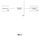
- FIG. 2shows a schematic diagram of a dead band DC converter system
- FIG. 3shows an exemplary circuit diagram for a dead band DC-DC power converter
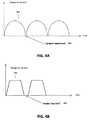
- FIG. 4Ashows an exemplary dead band DC waveform according to one embodiment
- FIG. 4Bshows an exemplary dead band DC waveform according to one embodiment
- FIG. 5Ashows a residential environment having a photovoltaic DC power system according to one embodiment
- FIG. 5Bis shows a schematic of a cable integrated dead band DC-DC converter system according to one embodiment
- FIG. 6Ashows an isometric view of a power converter cartridge and housing in which the power converter cartridge is detached from the housing according to one embodiment
- FIG. 6Bshows an isometric view of the power converter cartridge and housing of FIG. 2A in which the power converter cartridge is secured to the housing;
- FIG. 7shows isometric view of a cable-integrated dead band DC-DC converter according to another embodiment
- FIG. 8Ashows a plan view of cable-integrated dead band DC-DC converter according to yet another embodiment
- FIG. 8Bshows a plan view of the cable-integrated dead band DC-DC converter of FIG. 4A ;
- FIG. 9shows a schematic diagram of a conventional DC transmission and distribution system
- FIG. 10shows a schematic diagram of a dead band DC transmission and distribution system according to another embodiment.
- a dead band DC distribution systeminserts regular periods of zero voltage or “dead time” into a DC power signal.
- the dead band DC converter systemalso advantageously shapes the DC power signal into a shaped waveform described in further detail herein.
- a dead band DC distribution systemis provided that allows power to be more easily interrupted by a circuit breaker.
- the dead band DC converter systemis configured so that standard AC rated breakers can be used instead of typically more expensive DC rated breakers to protect against sustained arcs and overcurrent conditions.
- the dead band DC distribution systemif an arc develops in the dead band DC distribution system (for example due to faulty wiring or a damaged connector), the arc that is created by the fault will extinguish during the next regular period of zero voltage. In this way, the dead band DC distribution system will behave similarly to an AC system, in which arcs typically extinguish when the AC signal crosses through zero volts.
- this techniquewill allow the use of smaller AC rated equipment such as circuit breakers in DC electrical distribution systems, saving significantly on cost and size.
- the period of zero voltagecan be adjusted based on the voltage and/or current level.
- a variety of wave shapes in the waveformcan be utilized for this purpose to optimize transmission of electric power, each of which includes a regular period of zero voltage (e.g., as shown in relation to FIGS. 4A and 4B described below).
- the dead time in the shaped waveformmatches the zero crossing advantage of traditional AC waveforms without requiring full inversion of the power to AC.
- FIG. 2shows a schematic diagram of a dead band DC converter system.
- the example embodimentincludes a DC power source 202 .
- DC power source 202can be embodied by one or more of a plurality of DC power sources, such as a solar panel, an array of solar panels, a windmill, a fuel cell, a generator, a battery, an AC-to-DC transformer or a combination of one or more of a plurality of DC power sources, including those not listed here.
- the example embodiment of FIG. 2also includes a dead band DC converter 204 receiving DC power from DC power source 202 .
- dead band DC converter 204is configured to convert a standard DC waveform, such as waveform 103 , into a shaped dead band DC waveform. Converting standard DC waveforms into dead band DC waveforms are discussed in further detail in relation to FIGS. 3, 4A, and 4B .
- the example embodiment of FIG. 2also includes an electric network interface 206 , which receives the shaped dead band DC waveform from dead band DC converter 204 .
- electric network interface 206is configured as an inverter to invert the shaped dead band DC waveform from dead band DC converter 204 into an output AC waveform.
- the output AC waveformis configured to be output into an AC power network, such as a local power utility grid.
- electric network interface 206is configured to output the dead band DC waveform from dead band DC converter 204 to a DC distribution system, such as DC distribution system in a home or business. In some examples, electric network interface 206 is configured to directly output the dead band DC waveform from dead band DC converter 204 to the DC distribution system. In some examples, electric network interface 206 is configured to transform the dead band DC waveform to a higher or lower voltage according to the configuration of the DC distribution system.
- electric network interface 206is configured to output both an AC signal for an AC power network, such as outputting to a local power utility, and a DC distribution system, such as DC distribution system in a home or business.
- a DC distribution systemsuch as DC distribution system in a home or business.
- the proportion of the amount of output sent as an AC signal to the AC power network, versus the output sent as a DC signaldepends on factors such as the amount of power supplied by DC power source 202 , the power demand of the DC distribution system, a user's preferences, and/or the power demand of the AC power network.
- electric network interface 206may direct most or all of the power from DC power source 202 and dead band DC converter 204 to the DC distribution system for use in the home instead of directing the power to the AC power network.
- electric network interfacemay be configured to output most or all of the power from DC power source 202 and dead band DC converter 204 to the AC power network, such as a local utility grid.
- FIG. 3shows a circuit diagram for a dead band DC-DC power converter 300 .
- dead band DC-DC power converter 300may be embodied in converters such as dead band DC converter 204 or other embodiments described herein.
- the input DC poweris supplied from DC power 302 .
- DC power 302may be DC power source 202 or other embodiments described herein.
- dead band DC-DC power converter 300includes switching transistors 304 and 306 , which may be configured to regulate power flow through the converter to the output dead band DC power 308 .
- the switching transistors 304 and 306are configured to vary switching times in the converter to convert a flat standard DC waveform such as waveform 103 into a shaped DC waveform with a “dead time” or to insert a dead band into the signal.
- FIGS. 4A and 4Bshow example waveforms, which may be generated by dead band DC-DC power converter 300 .
- waveform 402may be generated by switching transistors 304 and 306 and by including a variable dead time 404 to create a dead band DC waveform, such as a dead band rectified sine waveform represented in waveform 402 .
- waveform 406may be generated by switching transistors 304 and 306 and include a variable dead time 408 to create an alternate dead band DC waveform.
- the variable dead times 404 and 408are similar to the AC voltage waveform zero crossing 102 as shown in FIG. 1A , allowing for standard AC rated equipment, such as AC circuit breakers to be used for overcurrent and arc protection.
- variable dead times 404 and 408can be adjusted for time length such that power transmission is optimized while still providing the advantages of the dead band DC power.
- variable dead times 404 and 408may comprises a non-zero voltage, such that the voltage of the output is low enough to function as a dead band and allow for extinguishing arcs, and use of AC equipment.
- the shaping of standard DC of both waveforms 404 and 408allows for easier utilization of standard DC power into other applications such as outputting to an AC power network or distribution in a dead band DC distribution system.
- the shaped waveform 402is similar to a rectified AC sine waveform, thus allowing easy inversion of waveform 402 into a standard AC waveform, such as waveform 101 , for output onto a local grid.
- the shaping of the standard DC waveform into a shaped waveformallows for insertion of dead bands into the waveform without causing an increased electromagnetic interference which may be caused by sharp changes in voltage or current.
- DC-DC power converter 300may be embodied in dead band DC converter 204 , wherein dead band DC converter 204 is configured to be connected to an input DC power source, such as DC power source 202 , and detect properties of the input DC power source, such as voltage or current.
- dead band DC converter 204is configured to determine properties for an output DC signal, such as voltage, dead band time, and waveform.
- the DC converter, such as dead band DC converter 204is in communication with an electric network interface, such as electric network interface 206 , which may specify properties for the output DC signal, such as output dead band DC power 308 .
- dead band DC converter 204may be configured to determine, from the specified properties, that the output DC signal should have 100 microsecond dead time and have a waveform suitable for inversion to an AC signal, such as waveform 402 .
- dead band DC converter 204is configured to control switching transistors 304 and 306 to produce a desired output dead band DC power 308 from the input DC power source 302 , having the specified properties, including an adjustable voltage, dead band time, and waveform.
- input DC power 302 and output power 308can be single phase 120 volt electrical system.
- the convertercan be used to generate a rectified voltage at the output 308 , similar to the waveform shown in FIG. 4A .
- switching transistors 304 and 306may be configured to include a 100 microsecond dead time or dead band, such as variable dead times 404 and 408 , approximately every 8.33 milliseconds. An approximate 8.33 millisecond interval would correspond to a rectified AC 60 Hz signal, but the invention is suitable for use with other types of electrical systems, including 50 hertz electric systems.
- switching transistors 304 and 306may be configured to insert longer or shorter dead times or dead bands over longer or shorter times spans.
- the present inventionis suitable for many types of DC power sources such as with other types of renewable energy sources such as windmills, water wheels, geothermal and is suitable for with other types energy storages devices such as fuel cells, capacitor banks and/or the like.
- the dead band DC distribution systemis embodied as a cable-integrated converter system provided for converting DC power received from photovoltaic cells into dead band DC power.
- the cable-integrated converter systemcan be used in conjunction with a variety of photovoltaic power systems, including systems in industrial, commercial, residential, and/or other power generation transmission and distribution environments.
- FIG. 5Ashows a building structure 5 having a photovoltaic power system interconnected with dead band DC distribution system 9 routed through structure 5 .
- the photovoltaic power systemincludes a photovoltaic solar array 10 .
- the solar array 10is configured to generate power in combination with a wind turbine 20 , which can be stored in an energy storage unit (e.g., comprised of the illustrated battery array 22 and a fuel cell array 24 ).
- an energy storage unite.g., comprised of the illustrated battery array 22 and a fuel cell array 24 .
- a fuel operated generator 26is also provided for emergency operation.
- the photovoltaic solar array 10 of FIG. 5Acomprises a plurality of photovoltaic solar panels 11 - 18 .
- the building structure 5has been shown as a residential building structure, it should be understood that the photovoltaic solar array 10 may be mounted on virtually any type of building structure or on a ground surface.
- each of the plurality of photovoltaic solar panels 11 - 18is made from a multiplicity of photovoltaic solar cells 19 .
- Each of the photovoltaic solar cells 19may generate, for example, approximately 0.5 volts. When connected in series—parallel, the cells 19 together may provide, for example, approximately 300 watts of power at 30 volts.
- individual photovoltaic solar panels 11 - 18are mounted on equatorial mounts (not shown) for following the movement of the sun throughout the day.
- FIG. 5Bshows a schematic diagram of a cable-integrated converter system 108 according to one embodiment.
- the cable-integrated converter system 501includes a trunk cable 502 , a plurality of power converters 606 distributed along the trunk cable 502 , and an electric network interface 206 .
- the power converters 606are each electrically connected to one of a plurality of photovoltaic modules 11 - 18 .
- the power converters 606are also connected to one another in series via the trunk cable 502 .
- the power converters 606are each configured to function as a dead band DC power converter, such as dead band DC converter 204 .
- the power converters 606convert DC power received from the photovoltaic modules 11 - 18 into a variety of shaped DC waveforms with dead bands, including, for example a rectified half-sine wave signal with a dead band or waveforms 402 and 404 , which are added and delivered via the trunk cable 502 to electric network interface 206 .
- multiple power converterssuch as power converters 606
- feeding into a single linerequires that power converters are highly synchronized in order to prevent failures in the equipment due to differences in synchronization.
- electric network interface 206is configured to communicate with power converters 606 through trunk cable 502 , and provide the necessary parameters to ensure synchronization.
- the inclusion of the dead bandadvantageously aids in this synchronization. For example, in DC to AC inversion, the dead band allows for an improved synchronization between the signal switching between positive and negative signals.
- the power convertersare integrated into the trunk cable 502 , which connects the power converters 606 in series.
- the trunk cable 502comprises a 30-ampere rated AC cable.
- the trunk cable 502comprises a 20-ampere rated AC cable.
- the trunk cable 502extends between the integrated power converters 606 , which can be embedded, enclosed, or otherwise integrated into the cable in a variety of ways.
- trunk cable 502comprises at least two wires for power transmission and two wires for communication between power converters 606 and electric network interface 206 .
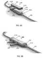
- FIG. 6Ashows an isometric view of a cable-integrated dead band DC power converter 606 according to one embodiment.
- the power converter 606comprises a removable cartridge 611 that can be selectively removed from the trunk cable 502 .
- the power converter cartridge 611is configured to be selectively secured to a housing 608 .
- the housing 608may be constructed from a thermally conductive material (e.g., metals, metal alloys, thermally conductive plastic, a combination of plastics and metals and/or the like).
- the housing 608may be constructed from thermally conductive plastic and include a metal heat-sink.
- the power converter cartridge 611may be constructed from similar thermally conductive materials and in similar manner.
- the housing 608is a generally rigid member defining a generally horizontal, flat base and a central recessed area 614 configured for receiving the removable power converter cartridge 611 .
- Opposing ends of the housing 608are attached to the trunk cable 502 .
- the trunk cable 502is secured to the housing 608 in a weather-proof manner (e.g., via weather-proof rubber grommets 613 a , 613 b , or by over molding the housing onto the trunk cable).
- the power converter cartridge 611defines a generally rigid exterior shell configured for insertion into the recessed area 614 of the housing 608 . As explained in greater detail below, the power converter's electronic components are sealed within the cartridge 611 and thereby shielded from outside weather. As shown in FIG. 6A , the power converter cartridge 611 includes positive and negative terminals 602 , 604 configured for connection to the photovoltaic modules ( 11 - 18 ). In particular, the terminals 602 , 604 enable the power converter 606 to receive DC power from the photovoltaic modules ( 11 - 18 ), which the power converter 606 then converts into a shaped DC wave form with dead band, as described below.
- the power converter cartridge 611also includes connection terminals 610 b on its opposing ends for providing an electrical connection between the power converter cartridge 611 and its housing 608 .
- the housing 608includes corresponding connection terminals 610 a , which protrude inwardly into the housing's recessed area 614 .
- the power converter cartridge's connector terminals 610 bare conductive cavities configured for reviving the housing's connector terminals 610 a .
- the connecters 610 a and 610 bhelp secure the power converter cartridge 611 in housing 608 .
- the power converter cartridge 611 and housing 608each include two connecters.
- the power converter cartridge 611 and housing 608include a single connector or multiple connecters (e.g., three connecters, four connecters, five connecters and/or the like).
- the connectersmay comprise flat electrical contacts that are merely in contact with one another.
- the electrical connectorsare configured to provide dedicated electrical connections between the power converter 606 , adjacent power converters 606 , and the above-described electric network interface 206 .
- the electrical connectorsinclude a power connection line, a fault detection line, and a synchronization line between the power converters 606 and electric network interface 206 .
- the power converter cartridgeis configured to be removably secured within the housing 608 .
- FIG. 6Bshows the power converter cartridge 611 secured within housing 608 .
- the housing 608may include a latch or other fastening device (not shown) for securing and/or releasing the power converter cartridge.
- the shape of the housing 608facilitates the power converter cartridge 611 snapping in place when inserted into the housing.
- power converters 606may include a light emitting diode (LED) to indicate that status of the power converter.
- LEDmay display a green light if the power converter is properly secured in place.
- the LEDmay display a red light if the power converter is loose and/or not properly secured within housing 608 .
- the power converter 606 electronicsare contained within the power converter cartridge 611 .
- a jumper cartridgemay be inserted to bridge the gap left by the power converter cartridge.
- a set of connectorsmay be provided to connect the power converter to the cable. The connectors left on the cable after removal of the power converter can then be directly connected together, thereby connecting the gap left from removal of the converter.
- a power converter 606when a power converter 606 is determined to be faulty, it may be easily replaced by inserting a new power converter cartridge 611 into a respective housing 608 .
- each of the power converters 606 shown in FIG. 5Bmay take the configuration shown and described with respect to FIGS. 6A and 6B .
- the systemmay comprise numerous power converters 606 (e.g., 10 power converters) spread evenly along a length of the trunk cable 502 in order to facilitate ease of connection to photovoltaic modules.
- FIG. 7shows an isometric view of a cable-integrated dead band DC power converter 606 according to another embodiment.
- the power converter's electronicsare contained within a housing 711 , which may be sealed for weather proofing.
- the power converter's housingincludes positive and negative terminals 705 , 708 , which are configured to enable the power converter to be connected to a photovoltaic module.
- the housing 711also includes terminals 702 a , 702 b , and 702 c disposed on its opposing ends.
- the terminals 702 a , 702 b , and 702 cconfigured to provide a detachable electrical connection with the trunk cable 502 at both ends of the housing 711 .
- the trunk cable 502includes corresponding connection terminals 704 a , 704 b , and 704 c .
- the opposite end of the power converter 606(obstructed from view in FIG. 7 ) is connected to a second section of the trunk cable 502 in the same fashion.
- the corresponding pairs of power converter and trunk cable connection terminals 702 a / 704 a ; 702 b / 704 b ; and 702 c / 704 care configured to provide dedication electrical connections between the power converter 606 , adjacent power converters 606 , and the above-described electric network interface 206 .
- the terminals 702 a / 704 aconnect a power connection line
- the terminals 702 b / 704 bconnect a fault detection line
- the terminals 702 c / 704 cconnect a synchronization line, each of which is established between the power converters 606 and electric network interface 206 .
- the terminals 702 a / 704 a , 702 b / 704 b , and 702 c / 704 cmay be integrated into a single multi-pin interface.
- a faulty power converter 606may be replaced by disconnecting the trunk cable 502 from the power converter 606 and connecting the trunk cable 502 to a new power converter 606 of the same type.
- the practical operation of the cabling system of FIG. 7is similar to the operation described above with reference to FIG. 6A and FIG. 6B .
- FIGS. 8A and 8Bshow an overhead view of a cable-integrated dead band DC power converter 606 according to another embodiment.
- the power converter's electronicsare contained within a power converter cartridge 811 configured for being removably secured between brackets 804 and 802 disposed at ends of sections of the trunk cable 502 .
- the power converter cartridge 811is configured for being connected via positive and negative terminals (not shown) to a photovoltaic module ( 11 - 18 ) as described above.
- brackets 804 and 802are configured for removable attachment to opposite ends of the power converter cartridge 811 .
- bracket 804includes protruding elements 804 a and 804 b for removably attaching trunk cable 502 to the power converter cartridge 811 .
- bracket 802includes protruding elements 802 a and 802 b for removably attaching trunk cable 502 to the power converter cartridge 811 .
- the shape of the edges of brackets 804 and 802correspond to the shape of the edges of the power converter cartridge 811 . Inserting the power converter cartridge 811 into bracket 802 secures the power converter cartridge 811 between elements 802 a and 802 b .
- bracket 802secures the power converter cartridge 811 between elements 804 a and 804 b .
- the protruding elements 804 a,b ; 802 a,bmay be configured to partially surround and engage the power converter cartridge 811 using a press-fit configuration, snap-fit configuration, a latch, a magnetic attachment, or by other suitable means.
- FIG. 8Ashows the power converter cartridge 811 disconnected from trunk cable 502
- FIG. 8Bshows the power converter cartridge 811 connected and secured to the trunk cable 502
- the trunk cable 502is electrically connected to the brackets 804 and 802 (e.g., with weather-proof rubber grommets 813 a , 813 b to secure the connection).
- the brackets 804 , 802are configured for electrically connecting the power converter cartridge 811 to the trunk cable 502 via projecting terminals 806 a and 808 a .
- the projecting terminals 806 a and 808 aare configured for insertion into corresponding terminals 806 b and 808 b of the power converter cartridge 811 .
- inserting the terminals 806 a into the terminals 806 bestablishes an electrical connection between a first section of the trunk cable 502 and the power converter cartridge 811
- inserting the terminals 808 a into the terminals 808 bestablishes an electrical connection between a second section of the trunk cable 502 and the power converter cartridge 811
- the connected terminals 808 and 806help secure the power converter cartridge 811 to the brackets 802 , 804 and trunk cable 502 .
- the corresponding pairs of power converter cartridge 811 and trunk cable 502 connection terminals 808 a / 808 b , and 806 a / 406 bare configured to provide dedicated electrical connections between the power converter 606 , adjacent power converters 606 , and the above-described electric network interface 206 .
- the three prongs of the electrical connections 808 a,b and 806 a,b shown in FIGS. 8A and 8Brepresent a power connection line, a fault detection line, and a synchronization line, respectively.
- the connection terminalsmay be integrated into a single multi-pin interface or any other suitable electrical connection interface.
- the power converter cartridge 811 and housing 608may include a single connector or multiple connecters (e.g., four connecters, five connecters and/or the like). Additionally, in further embodiments, the connecters may comprise flat electrical contacts that are merely in contact with one another.
- FIG. 9shows a schematic diagram of an alternate DC transmission and distribution system 900 , without dead band DC converters, which may be improved by various embodiments describe herein.
- DC transmission and distribution 900photovoltaic solar array 10 produces power directly, as a standard DC waveform, such as waveform 103 , into a DC transmission and distribution system 904 .
- a standard DC waveformsuch as waveform 103
- DC transmission and distribution system 904In order for DC transmission and distribution system 904 to be safe for distribution through an industrial, commercial, residential, and/or other power generation transmission and distribution environments such as a home or business, expensive DC safety precautions must be put into place. For example, DC circuit breaker 902 , must be installed to prevent continuous arc faults from developing in system 904 .
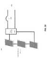
- FIG. 10shows a schematic diagram of a dead band DC transmission and distribution system 1000 .
- the system 1000includes a single dead band DC-DC converter 1002 .
- DC-DC converter 1002may be configured for converting DC power produced by photovoltaic solar array 10 to a dead band DC signal or waveform for distribution.
- DC-DC converter 1002may comprise both a dead band DC converter 204 and an electric network interface 206 to output a dead band DC power signal to a DC distribution network 1006 .
- a DC distribution network 1006may provide power to an LED lighting network in a home or business.
- DC-DC converter 1002may output a dead band DC power signal directly to the LED lighting network.
- dead band DC transmission and distribution system 1000does not require more expensive DC rated equipment such as DC circuit breaker 902 , but can instead utilize more common and less expensive AC circuit breaker 1004 to extinguish faults in the DC transmission and distribution system 1000 .
Landscapes
- Engineering & Computer Science (AREA)
- Power Engineering (AREA)
- Direct Current Feeding And Distribution (AREA)
- Inverter Devices (AREA)
- Photovoltaic Devices (AREA)
Abstract
Description
Claims (16)
Priority Applications (1)
| Application Number | Priority Date | Filing Date | Title |
|---|---|---|---|
| US15/805,979US10523117B2 (en) | 2016-11-07 | 2017-11-07 | Dead band direct current converter |
Applications Claiming Priority (2)
| Application Number | Priority Date | Filing Date | Title |
|---|---|---|---|
| US201662418540P | 2016-11-07 | 2016-11-07 | |
| US15/805,979US10523117B2 (en) | 2016-11-07 | 2017-11-07 | Dead band direct current converter |
Publications (2)
| Publication Number | Publication Date |
|---|---|
| US20180131272A1 US20180131272A1 (en) | 2018-05-10 |
| US10523117B2true US10523117B2 (en) | 2019-12-31 |
Family
ID=60413291
Family Applications (1)
| Application Number | Title | Priority Date | Filing Date |
|---|---|---|---|
| US15/805,979Active2037-12-04US10523117B2 (en) | 2016-11-07 | 2017-11-07 | Dead band direct current converter |
Country Status (6)
| Country | Link |
|---|---|
| US (1) | US10523117B2 (en) |
| EP (1) | EP3535825A1 (en) |
| CN (2) | CN110168828A (en) |
| AU (1) | AU2017355719B2 (en) |
| CA (1) | CA3043196A1 (en) |
| WO (1) | WO2018085849A1 (en) |
Cited By (4)
| Publication number | Priority date | Publication date | Assignee | Title |
|---|---|---|---|---|
| US10951161B2 (en) | 2015-12-18 | 2021-03-16 | Southwire Company, Llc | Cable integrated solar inverter |
| US11251621B1 (en)* | 2017-08-03 | 2022-02-15 | Southwire Company, Llc | Solar power generation system |
| US11956875B1 (en) | 2017-08-11 | 2024-04-09 | Southwire Company, Llc | DC power management system |
| US12382520B2 (en)* | 2022-11-11 | 2025-08-05 | Tigo Energy, Inc. | Solar panel transmitter pairing process |
Citations (66)
| Publication number | Priority date | Publication date | Assignee | Title |
|---|---|---|---|---|
| JPH10174452A (en) | 1996-12-10 | 1998-06-26 | Omron Corp | Power conversion device, inverter and photovoltaic power generation system |
| US6111767A (en) | 1998-06-22 | 2000-08-29 | Heliotronics, Inc. | Inverter integrated instrumentation having a current-voltage curve tracer |
| JP2001238466A (en) | 2000-02-28 | 2001-08-31 | Matsushita Electric Ind Co Ltd | Grid-connected inverter device |
| US6429546B1 (en) | 1998-11-20 | 2002-08-06 | Georgia Tech Research Corporation | Systems and methods for preventing islanding of grid-connected electrical power systems |
| WO2003077398A2 (en) | 2002-03-08 | 2003-09-18 | Aloys Wobben | Separate network and method for operating a separate network |
| US20060002110A1 (en) | 2004-03-15 | 2006-01-05 | Color Kinetics Incorporated | Methods and systems for providing lighting systems |
| US20080285317A1 (en) | 2007-05-17 | 2008-11-20 | Larankelo, Inc. | Photovoltaic module-mounted ac inverter |
| US20100066260A1 (en) | 2008-09-05 | 2010-03-18 | Lutron Electronics Co., Inc. | Hybrid light source |
| US20100071742A1 (en) | 2008-09-19 | 2010-03-25 | General Electric Company | Quasi-AC, photovoltaic module for unfolder photovoltaic inverter |
| US20100134959A1 (en) | 2008-11-11 | 2010-06-03 | Fife John M | Solar power inverters, including temperature-controlled solar power inverters, and associated systems and methods |
| US20100141158A1 (en) | 2008-09-05 | 2010-06-10 | Newman Jr Robert C | Hybrid light source |
| US20100263704A1 (en) | 2009-04-16 | 2010-10-21 | Enphase Energy, Inc. | Apparatus for coupling power generated by a photovoltaic module to an output |
| US20100289337A1 (en) | 2009-05-13 | 2010-11-18 | Solar Semiconductor, Inc. | Methods and apparatuses for photovoltaic power management |
| US20100307479A1 (en) | 2009-06-03 | 2010-12-09 | Ken Hyun Park | Solar Panel Tracking and Mounting System |
| US20110061705A1 (en) | 2009-09-11 | 2011-03-17 | Miasole | Rotatable junction box for a solar module |
| US20110090089A1 (en) | 2009-10-15 | 2011-04-21 | Yuhao Luo | Method and apparatus for detecting a fault in a solar cell panel and an inverter |
| US20110121744A1 (en) | 2009-11-20 | 2011-05-26 | Lutron Electronics Co., Inc. | Controllable-load circuit for use with a load control device |
| US20110202181A1 (en) | 2010-02-12 | 2011-08-18 | Enphase Energy, Inc. | Method and apparatus for smart climate control |
| US20110210611A1 (en) | 2008-10-10 | 2011-09-01 | Ampt, Llc | Novel Solar Power Circuits |
| US20110225904A1 (en) | 2010-03-19 | 2011-09-22 | Sudhir Railkar | Slate Style Roofing System with Integrated Solar Panels |
| US20110248640A1 (en) | 2008-09-05 | 2011-10-13 | Petrus Johannes Maria Welten | Led based lighting application |
| US20110273015A1 (en) | 2006-12-06 | 2011-11-10 | Solaredge Technologies Ltd. | Distributed power harvesting systems using dc power sources |
| US20110273016A1 (en) | 2007-12-04 | 2011-11-10 | Solaredge Technologies Ltd. | Distributed power harvesting systems using dc power sources |
| US20120019074A1 (en) | 2011-09-29 | 2012-01-26 | Sunlight Photonics Inc. | Methods and apparatus for high-frequency electrical power collection and transfer |
| US8106537B2 (en) | 2008-07-01 | 2012-01-31 | Satcon Technology Corporation | Photovoltaic DC/DC micro-converter |
| US8134820B1 (en) | 2007-09-10 | 2012-03-13 | Technology Reasearch Corporation | Contactor control circuit |
| US20120080944A1 (en) | 2006-03-28 | 2012-04-05 | Wireless Environment, Llc. | Grid Shifting System for a Lighting Circuit |
| US20120081934A1 (en) | 2011-11-01 | 2012-04-05 | Paul Garrity | Photovoltaic power conditioning units |
| US20120084027A1 (en) | 2010-10-05 | 2012-04-05 | Also Energy, Inc. | System and method for monitoring performance of a photovoltaic array |
| US20120089260A1 (en) | 2010-10-11 | 2012-04-12 | Solarbridge Technologies, Inc. | System and method for establishing communication with an array of inverters |
| US20120138123A1 (en) | 2009-08-14 | 2012-06-07 | Newdoll Enterprises Llc | Enhanced solar panels, liquid delivery systems and associated processes for solar energy systems |
| US8207637B2 (en) | 2009-10-09 | 2012-06-26 | Solarbridge Technologies, Inc. | System and apparatus for interconnecting an array of power generating assemblies |
| US20120175955A1 (en) | 2011-01-12 | 2012-07-12 | The Boeing Company | Smart microgrid reconfigurable ac interface |
| US20120175964A1 (en) | 2011-01-12 | 2012-07-12 | Solaredge Technologies Ltd. | Serially connected inverters |
| US8257106B2 (en) | 2010-01-25 | 2012-09-04 | Enphase Energy, Inc. | Method and apparatus for interconnecting distributed power sources |
| US20120248863A1 (en) | 2006-12-06 | 2012-10-04 | Solaredge Technologies Ltd. | Safety Mechanisms, Wake Up and Shutdown Methods in Distributed Power Installations |
| US20120310427A1 (en) | 2011-05-31 | 2012-12-06 | Williams B Jeffery | Automatic Monitoring and Adjustment of a Solar Panel Array |
| WO2012170726A2 (en) | 2011-06-07 | 2012-12-13 | Transform Solar Pty Ltd. | Solar panel systems having solar panels arranged in parallel, and associated methods |
| US20120313443A1 (en) | 2011-06-10 | 2012-12-13 | Cyboenergy, Inc. | Smart and scalable off-grid mini-inverters |
| US20130002031A1 (en) | 2011-06-30 | 2013-01-03 | Cyboenergy, Inc. | Enclosure and Message System of Smart and Scalable Power Inverters |
| US20130021006A1 (en) | 2011-07-18 | 2013-01-24 | Enphase Energy, Inc. | Method and apparatus for multi-phase power transfer |
| US8410950B2 (en) | 2009-08-17 | 2013-04-02 | Paceco Corp. | Photovoltaic panel monitoring apparatus |
| US20130113291A1 (en) | 2006-03-28 | 2013-05-09 | Wireless Environment, Llc | Distributed energy managment using grid-shifting devices |
| WO2013107782A2 (en) | 2012-01-17 | 2013-07-25 | Infineon Technologies Austria Ag | Power converter circuit, power supply system and method |
| US20130241535A1 (en) | 2010-11-10 | 2013-09-19 | Sma Solar Technology Ag | Method for Verifying an Electrical Connection Between a Generator and an Inverter |
| US8581441B2 (en) | 2007-05-17 | 2013-11-12 | Enphase Energy, Inc. | Distributed inverter and intelligent gateway |
| US20130346054A1 (en) | 2012-06-26 | 2013-12-26 | Asim Mumtaz | System, method and apparatus for generating layout of devices in solar installations |
| US8626616B2 (en) | 2010-04-01 | 2014-01-07 | Enphase Energy, Inc. | Method and apparatus for managing installation information |
| US20140077609A1 (en) | 2012-09-19 | 2014-03-20 | Enphase Energy, Inc. | Serially connected micro-inverter system with trunk and drop cabling |
| US20140191583A1 (en) | 2013-01-04 | 2014-07-10 | Enecsys Limited | Power balancing in a multi-phase system |
| US8824178B1 (en) | 2009-12-31 | 2014-09-02 | Solarbridge Technologies, Inc. | Parallel power converter topology |
| US20140265585A1 (en) | 2013-03-15 | 2014-09-18 | Technology Research Corporation | Interface for renewable energy system |
| US20140266289A1 (en) | 2013-03-15 | 2014-09-18 | Technology Research Corporation | Interface for renewable energy system |
| CN104158394A (en) | 2014-07-08 | 2014-11-19 | 安徽金峰新能源股份有限公司 | Auto-starting control method for photovoltaic inverter |
| US20140361695A1 (en) | 2011-10-04 | 2014-12-11 | Citizen Electronics Co., Ltd. | Led lighting device |
| US20150237700A1 (en) | 2011-07-26 | 2015-08-20 | Hunter Industries, Inc. | Systems and methods to control color and brightness of lighting devices |
| US20150244250A1 (en) | 2012-10-03 | 2015-08-27 | Belenos Clean Power Holding Ag | Regulation of an electronic voltage adapter module |
| US9165275B2 (en) | 2009-07-14 | 2015-10-20 | Emphase Energy, Inc. | Method and apparatus for identifying redeployed distributed generator components |
| US20160072396A1 (en) | 2014-09-08 | 2016-03-10 | Infineon Technologies Austria Ag | Multi-cell power conversion method and multi-cell power converter |
| US20160226252A1 (en) | 2015-02-02 | 2016-08-04 | Technology Research, Llc | Interface for renewable energy system |
| US20170019960A1 (en) | 2015-07-14 | 2017-01-19 | The Hong Kong Polytechnic University | Multi-string led driver with current balancing |
| US20170027029A1 (en) | 2011-03-17 | 2017-01-26 | Shanghai Sim-Bcd Semiconductor Manufacturing Co., Ltd. | Power supply for led lamp with triac dimmer |
| US20170223807A1 (en) | 2006-03-28 | 2017-08-03 | Wireless Environment, Llc. | Cloud connected lighting system |
| US20170231058A1 (en) | 2014-08-04 | 2017-08-10 | Innosys, Inc. | Lighting Systems |
| US20170238401A1 (en) | 2014-01-25 | 2017-08-17 | Innosys, Inc. | Solid State Lighting Systems |
| US9750102B1 (en) | 2016-04-06 | 2017-08-29 | Power Integrations, Inc. | Switch current control to shape input current |
Family Cites Families (8)
| Publication number | Priority date | Publication date | Assignee | Title |
|---|---|---|---|---|
| US20120033392A1 (en)* | 2010-08-09 | 2012-02-09 | Tyco Electronics Corporation | Modular Junction Box for a Photovoltaic Module |
| CN102386259A (en)* | 2010-09-02 | 2012-03-21 | 国琏电子(上海)有限公司 | Wiring box |
| GB2489468A (en)* | 2011-03-29 | 2012-10-03 | Sony Corp | Grid tied inverter having DC-DC current fed push-pull converter |
| CN102779871A (en)* | 2011-05-11 | 2012-11-14 | 无锡尚德太阳能电力有限公司 | Photovoltaic module junction box |
| EP2621075B1 (en)* | 2012-01-27 | 2020-07-29 | LG Electronics Inc. | Power converting apparatus and photovoltaic module |
| US10027114B2 (en)* | 2012-10-25 | 2018-07-17 | Mpowersolar Inc. | Master slave architecture for distributed DC to AC power conversion |
| CN205490397U (en)* | 2016-02-24 | 2016-08-17 | 康联精密机电(深圳)有限公司 | Press from both sides and weld dual -purpose solar junction box |
| CN105763152B (en)* | 2016-03-15 | 2018-10-30 | 浙江英达威芯电子有限公司 | A kind of terminal box, photovoltaic module and its system |
- 2017
- 2017-11-07EPEP17801567.3Apatent/EP3535825A1/ennot_activeWithdrawn
- 2017-11-07AUAU2017355719Apatent/AU2017355719B2/ennot_activeCeased
- 2017-11-07WOPCT/US2017/060428patent/WO2018085849A1/ennot_activeCeased
- 2017-11-07CACA3043196Apatent/CA3043196A1/enactivePending
- 2017-11-07CNCN201780082327.XApatent/CN110168828A/enactivePending
- 2017-11-07USUS15/805,979patent/US10523117B2/enactiveActive
- 2017-11-07CNCN202411952716.1Apatent/CN120281176A/enactivePending
Patent Citations (72)
| Publication number | Priority date | Publication date | Assignee | Title |
|---|---|---|---|---|
| JPH10174452A (en) | 1996-12-10 | 1998-06-26 | Omron Corp | Power conversion device, inverter and photovoltaic power generation system |
| US6111767A (en) | 1998-06-22 | 2000-08-29 | Heliotronics, Inc. | Inverter integrated instrumentation having a current-voltage curve tracer |
| US6429546B1 (en) | 1998-11-20 | 2002-08-06 | Georgia Tech Research Corporation | Systems and methods for preventing islanding of grid-connected electrical power systems |
| JP2001238466A (en) | 2000-02-28 | 2001-08-31 | Matsushita Electric Ind Co Ltd | Grid-connected inverter device |
| WO2003077398A2 (en) | 2002-03-08 | 2003-09-18 | Aloys Wobben | Separate network and method for operating a separate network |
| US20060002110A1 (en) | 2004-03-15 | 2006-01-05 | Color Kinetics Incorporated | Methods and systems for providing lighting systems |
| US20130113291A1 (en) | 2006-03-28 | 2013-05-09 | Wireless Environment, Llc | Distributed energy managment using grid-shifting devices |
| US20120080944A1 (en) | 2006-03-28 | 2012-04-05 | Wireless Environment, Llc. | Grid Shifting System for a Lighting Circuit |
| US20170223807A1 (en) | 2006-03-28 | 2017-08-03 | Wireless Environment, Llc. | Cloud connected lighting system |
| US20120248863A1 (en) | 2006-12-06 | 2012-10-04 | Solaredge Technologies Ltd. | Safety Mechanisms, Wake Up and Shutdown Methods in Distributed Power Installations |
| US20110273015A1 (en) | 2006-12-06 | 2011-11-10 | Solaredge Technologies Ltd. | Distributed power harvesting systems using dc power sources |
| US20080285317A1 (en) | 2007-05-17 | 2008-11-20 | Larankelo, Inc. | Photovoltaic module-mounted ac inverter |
| US8581441B2 (en) | 2007-05-17 | 2013-11-12 | Enphase Energy, Inc. | Distributed inverter and intelligent gateway |
| US20130012061A1 (en) | 2007-05-17 | 2013-01-10 | Enphase Energy, Inc. | Photovoltaic ac inverter mount and interconnect |
| US8134820B1 (en) | 2007-09-10 | 2012-03-13 | Technology Reasearch Corporation | Contactor control circuit |
| US20110273016A1 (en) | 2007-12-04 | 2011-11-10 | Solaredge Technologies Ltd. | Distributed power harvesting systems using dc power sources |
| US8106537B2 (en) | 2008-07-01 | 2012-01-31 | Satcon Technology Corporation | Photovoltaic DC/DC micro-converter |
| US20100066260A1 (en) | 2008-09-05 | 2010-03-18 | Lutron Electronics Co., Inc. | Hybrid light source |
| US20100141158A1 (en) | 2008-09-05 | 2010-06-10 | Newman Jr Robert C | Hybrid light source |
| US20110248640A1 (en) | 2008-09-05 | 2011-10-13 | Petrus Johannes Maria Welten | Led based lighting application |
| US20100071742A1 (en) | 2008-09-19 | 2010-03-25 | General Electric Company | Quasi-AC, photovoltaic module for unfolder photovoltaic inverter |
| US20110210611A1 (en) | 2008-10-10 | 2011-09-01 | Ampt, Llc | Novel Solar Power Circuits |
| US20100134959A1 (en) | 2008-11-11 | 2010-06-03 | Fife John M | Solar power inverters, including temperature-controlled solar power inverters, and associated systems and methods |
| US20100263704A1 (en) | 2009-04-16 | 2010-10-21 | Enphase Energy, Inc. | Apparatus for coupling power generated by a photovoltaic module to an output |
| US8435056B2 (en) | 2009-04-16 | 2013-05-07 | Enphase Energy, Inc. | Apparatus for coupling power generated by a photovoltaic module to an output |
| US20100289337A1 (en) | 2009-05-13 | 2010-11-18 | Solar Semiconductor, Inc. | Methods and apparatuses for photovoltaic power management |
| US20100307479A1 (en) | 2009-06-03 | 2010-12-09 | Ken Hyun Park | Solar Panel Tracking and Mounting System |
| US9165275B2 (en) | 2009-07-14 | 2015-10-20 | Emphase Energy, Inc. | Method and apparatus for identifying redeployed distributed generator components |
| US20120138123A1 (en) | 2009-08-14 | 2012-06-07 | Newdoll Enterprises Llc | Enhanced solar panels, liquid delivery systems and associated processes for solar energy systems |
| US8410950B2 (en) | 2009-08-17 | 2013-04-02 | Paceco Corp. | Photovoltaic panel monitoring apparatus |
| US20110061705A1 (en) | 2009-09-11 | 2011-03-17 | Miasole | Rotatable junction box for a solar module |
| US8207637B2 (en) | 2009-10-09 | 2012-06-26 | Solarbridge Technologies, Inc. | System and apparatus for interconnecting an array of power generating assemblies |
| US20110090089A1 (en) | 2009-10-15 | 2011-04-21 | Yuhao Luo | Method and apparatus for detecting a fault in a solar cell panel and an inverter |
| US20110121744A1 (en) | 2009-11-20 | 2011-05-26 | Lutron Electronics Co., Inc. | Controllable-load circuit for use with a load control device |
| US8824178B1 (en) | 2009-12-31 | 2014-09-02 | Solarbridge Technologies, Inc. | Parallel power converter topology |
| US8257106B2 (en) | 2010-01-25 | 2012-09-04 | Enphase Energy, Inc. | Method and apparatus for interconnecting distributed power sources |
| US20110202181A1 (en) | 2010-02-12 | 2011-08-18 | Enphase Energy, Inc. | Method and apparatus for smart climate control |
| US20110225904A1 (en) | 2010-03-19 | 2011-09-22 | Sudhir Railkar | Slate Style Roofing System with Integrated Solar Panels |
| US8626616B2 (en) | 2010-04-01 | 2014-01-07 | Enphase Energy, Inc. | Method and apparatus for managing installation information |
| US20120084027A1 (en) | 2010-10-05 | 2012-04-05 | Also Energy, Inc. | System and method for monitoring performance of a photovoltaic array |
| US20120089260A1 (en) | 2010-10-11 | 2012-04-12 | Solarbridge Technologies, Inc. | System and method for establishing communication with an array of inverters |
| US20130241535A1 (en) | 2010-11-10 | 2013-09-19 | Sma Solar Technology Ag | Method for Verifying an Electrical Connection Between a Generator and an Inverter |
| US20120175964A1 (en) | 2011-01-12 | 2012-07-12 | Solaredge Technologies Ltd. | Serially connected inverters |
| US20120175955A1 (en) | 2011-01-12 | 2012-07-12 | The Boeing Company | Smart microgrid reconfigurable ac interface |
| US20170027029A1 (en) | 2011-03-17 | 2017-01-26 | Shanghai Sim-Bcd Semiconductor Manufacturing Co., Ltd. | Power supply for led lamp with triac dimmer |
| US20120310427A1 (en) | 2011-05-31 | 2012-12-06 | Williams B Jeffery | Automatic Monitoring and Adjustment of a Solar Panel Array |
| WO2012170726A2 (en) | 2011-06-07 | 2012-12-13 | Transform Solar Pty Ltd. | Solar panel systems having solar panels arranged in parallel, and associated methods |
| US20120313443A1 (en) | 2011-06-10 | 2012-12-13 | Cyboenergy, Inc. | Smart and scalable off-grid mini-inverters |
| US20130002031A1 (en) | 2011-06-30 | 2013-01-03 | Cyboenergy, Inc. | Enclosure and Message System of Smart and Scalable Power Inverters |
| US20130021006A1 (en) | 2011-07-18 | 2013-01-24 | Enphase Energy, Inc. | Method and apparatus for multi-phase power transfer |
| US20150237700A1 (en) | 2011-07-26 | 2015-08-20 | Hunter Industries, Inc. | Systems and methods to control color and brightness of lighting devices |
| US20120019074A1 (en) | 2011-09-29 | 2012-01-26 | Sunlight Photonics Inc. | Methods and apparatus for high-frequency electrical power collection and transfer |
| US20140361695A1 (en) | 2011-10-04 | 2014-12-11 | Citizen Electronics Co., Ltd. | Led lighting device |
| US8472220B2 (en) | 2011-11-01 | 2013-06-25 | Enecsys Limited | Photovoltaic power conditioning units |
| US20120081934A1 (en) | 2011-11-01 | 2012-04-05 | Paul Garrity | Photovoltaic power conditioning units |
| WO2013107782A2 (en) | 2012-01-17 | 2013-07-25 | Infineon Technologies Austria Ag | Power converter circuit, power supply system and method |
| US20130346054A1 (en) | 2012-06-26 | 2013-12-26 | Asim Mumtaz | System, method and apparatus for generating layout of devices in solar installations |
| US20140077609A1 (en) | 2012-09-19 | 2014-03-20 | Enphase Energy, Inc. | Serially connected micro-inverter system with trunk and drop cabling |
| US20150244250A1 (en) | 2012-10-03 | 2015-08-27 | Belenos Clean Power Holding Ag | Regulation of an electronic voltage adapter module |
| US20140191583A1 (en) | 2013-01-04 | 2014-07-10 | Enecsys Limited | Power balancing in a multi-phase system |
| WO2014152765A2 (en) | 2013-03-15 | 2014-09-25 | Technology Research Corporation | Interface for renewable energy system |
| CA2906590A1 (en) | 2013-03-15 | 2014-09-25 | Technology Research, Llc | Interface for renewable energy system |
| US20140266289A1 (en) | 2013-03-15 | 2014-09-18 | Technology Research Corporation | Interface for renewable energy system |
| US20140265585A1 (en) | 2013-03-15 | 2014-09-18 | Technology Research Corporation | Interface for renewable energy system |
| EP2973976B1 (en) | 2013-03-15 | 2019-05-01 | Technology Research, LLC | Interface for renewable energy system |
| US20170238401A1 (en) | 2014-01-25 | 2017-08-17 | Innosys, Inc. | Solid State Lighting Systems |
| CN104158394A (en) | 2014-07-08 | 2014-11-19 | 安徽金峰新能源股份有限公司 | Auto-starting control method for photovoltaic inverter |
| US20170231058A1 (en) | 2014-08-04 | 2017-08-10 | Innosys, Inc. | Lighting Systems |
| US20160072396A1 (en) | 2014-09-08 | 2016-03-10 | Infineon Technologies Austria Ag | Multi-cell power conversion method and multi-cell power converter |
| US20160226252A1 (en) | 2015-02-02 | 2016-08-04 | Technology Research, Llc | Interface for renewable energy system |
| US20170019960A1 (en) | 2015-07-14 | 2017-01-19 | The Hong Kong Polytechnic University | Multi-string led driver with current balancing |
| US9750102B1 (en) | 2016-04-06 | 2017-08-29 | Power Integrations, Inc. | Switch current control to shape input current |
Non-Patent Citations (26)
| Title |
|---|
| Argentine Patent and Trademark Office, Office Action for Argentine Patent Application No. 20140101267, Mar. 11, 2019, 5 pages, Argentina. |
| Chilean Patent and Trademark Office, Written Opinion for Chilean Patent Application No. 201502718, dated Jan. 15, 2018, 11 pages, Chile. |
| European Patent Office, Communication Pursuant to Rules 161(2) and 162 EPC for Application No. 14770361.5, Nov. 5, 2015, 2 pages, Germany. |
| European Patent Office, Communication Pursuant to Rules 70(2) and 70a(2) EPC for Application No. 14770361.5, Dec. 13, 2016, 1 page, Germany. |
| European Patent Office, Communication Under Rule 71(3) EPC for Application No. 14770361.5, Nov. 14, 2018, 61 pages, Germany. |
| European Patent Office, Extended European Search Report for Application No. 14770361.5, Nov. 24, 2016, 9 pages, Germany. |
| International Bureau of WIPO, International Preliminary Report on Patentability for International Application No. PCT/US2014/027708, dated Sep. 15, 2015, 22 pages, Switzerland. |
| International Searching Authority, International Search Report and Written Opinion for International Applicaiton No. PCT/US2016/067556, Mar. 16, 2017, 15 pages, The Netherlands. |
| International Searching Authority, International Search Report and Written Opinion for International Application No. PCT/ US2014/027708, dated oct. 2, 2014, 24 pages, United States Patent and Trademark Office, U.S.A. |
| International Searching Authority, International Search Report and Written Opinion for International Application No. PCT/US2016/016059, Jun. 27, 2016, 14 pages, The Netherlands. |
| International Searching Authority, International Search Report and Written Opinion for International Application No. PCT/US2017/060428, dated Feb. 7, 2018, 15 pages, European Patent Office, Netherlands. |
| Mexican Patent Office, Notice of Allowance for Mexican Patent Application No. MX/a/2015/012438, Jun. 11, 2018, 1 page, Mexico. |
| Mexican Patent Office, Office Action for Mexican Patent Application No. MX/a/2015/012438, Dec. 4, 2017, 2 pages, Mexico. |
| Microchip Technology Inc. Grid-Connected Solar Microinverter Reference Design Using a dsPIC® Digital Signal Controller, AN1338 Technical Bulletin, Jul. 2010, 56 pages, retrieved from <http://ww1.microchip.com/downloads/en/AppNotes/01338D.pdf> on Jul. 22, 2016. |
| Roos et al., Solar Electric System Design, Operation and Installation, Washington State University Extension Energy Program, Oct. 2009, (35 pages). [Retrieved from the Internet Aug. 6, 2019] <www.energy.wsu.edu/Documents/SolarPVforBuildersOct2009.pdf>. |
| U.S. Appl. No. 61/270,809, "Method and System for Locating Stolen Solar Power Systems Components", Unpublished (filed Jul. 14, 2009), (Martin Fronage, Inventor and Assignee). |
| United States Patent and Trademark Office, Corrected Notice of Allowability for U.S. Appl. No. 14/058,270, dated Dec. 28, 2016, 3 pages, U.S.A. |
| United States Patent and Trademark Office, Notice of Allowance for U.S. Appl. No. 14/058,270, dated Sep. 23, 2016, 12 pages, U.S.A. |
| United States Patent and Trademark Office, Notice of Allowance for U.S. Appl. No. 14/612,159, dated Jan. 3, 2017, 17 pges, U.S.A. |
| United States Patent and Trademark Office, Notice of Allowance for U.S. Appl. No. 15/425,767, dated Sep. 14, 2018, 13 pages, U.S.A. |
| United States Patent and Trademark Office, Office Action for U.S. Appl. No. 14/211,693, dated Apr. 21, 2017, 12 pages, U.S.A. |
| United States Patent and Trademark Office, Office Action for U.S. Appl. No. 14/211,693, dated Dec. 19, 2016, 8 pages, U.S.A. |
| United States Patent and Trademark Office, Office Action for U.S. Appl. No. 14/211,693, dated Mar. 11, 2016, 7 pages, U.S.A. |
| United States Patent and Trademark Office, Office Action for U.S. Appl. No. 15/383,647, dated May 1, 2019, 12 pages, U.S.A. |
| United States Patent and Trademark Office, Office Action for U.S. Appl. No. 16/100,961, dated Mar. 22, 2019, 19 pages, U.S.A. |
| Vu, Trung-Kien, et al., "A new adaptive dead-time compensation for single-phase grid-connected PV inverter", Proceeding of 26th Annual Applied Power Electronics Conference and Exposition (APEC), Mar. 6, 2011, pp. 923-930, IEEE, U.S. |
Cited By (6)
| Publication number | Priority date | Publication date | Assignee | Title |
|---|---|---|---|---|
| US10951161B2 (en) | 2015-12-18 | 2021-03-16 | Southwire Company, Llc | Cable integrated solar inverter |
| US11387775B2 (en) | 2015-12-18 | 2022-07-12 | Southwire Company, Llc | Cable integrated solar inverter |
| US11251621B1 (en)* | 2017-08-03 | 2022-02-15 | Southwire Company, Llc | Solar power generation system |
| US12184159B2 (en) | 2017-08-03 | 2024-12-31 | Southwire Company, Llc | Solar power generation system |
| US11956875B1 (en) | 2017-08-11 | 2024-04-09 | Southwire Company, Llc | DC power management system |
| US12382520B2 (en)* | 2022-11-11 | 2025-08-05 | Tigo Energy, Inc. | Solar panel transmitter pairing process |
Also Published As
| Publication number | Publication date |
|---|---|
| AU2017355719B2 (en) | 2022-09-08 |
| AU2017355719A1 (en) | 2019-06-27 |
| CN120281176A (en) | 2025-07-08 |
| US20180131272A1 (en) | 2018-05-10 |
| CN110168828A (en) | 2019-08-23 |
| WO2018085849A1 (en) | 2018-05-11 |
| CA3043196A1 (en) | 2018-05-11 |
| EP3535825A1 (en) | 2019-09-11 |
Similar Documents
| Publication | Publication Date | Title |
|---|---|---|
| US11387775B2 (en) | Cable integrated solar inverter | |
| US10833629B2 (en) | Interface for renewable energy system | |
| US9564756B2 (en) | Interface for renewable energy system | |
| US10523117B2 (en) | Dead band direct current converter | |
| US20130012061A1 (en) | Photovoltaic ac inverter mount and interconnect | |
| JP2012515519A (en) | Power supply system and solar cell device therefor | |
| US12184159B2 (en) | Solar power generation system | |
| US9548610B2 (en) | Control method for arranging DC/AC converters in parallel | |
| CN217642859U (en) | Low-carbon power supply control system for micro-grid of data center | |
| CN207099029U (en) | A kind of photovoltaic generating system | |
| KR101614951B1 (en) | Solar Photovoltaic Generation System | |
| KR101737970B1 (en) | Hybrid distributing board | |
| JP6719604B2 (en) | Power distribution equipment and power distribution method | |
| WO2012150574A1 (en) | Photovoltaic plant | |
| CN207977923U (en) | A kind of photovoltaic system switch board and photovoltaic generating system | |
| EP2418687A1 (en) | Photovoltaic panel comprising an inverter | |
| US20160329736A1 (en) | Solar power supplementation system | |
| KR20140077852A (en) | Photovoltaics system |
Legal Events
| Date | Code | Title | Description |
|---|---|---|---|
| FEPP | Fee payment procedure | Free format text:ENTITY STATUS SET TO UNDISCOUNTED (ORIGINAL EVENT CODE: BIG.); ENTITY STATUS OF PATENT OWNER: LARGE ENTITY | |
| AS | Assignment | Owner name:SOUTHWIRE COMPANY, LLC, GEORGIA Free format text:ASSIGNMENT OF ASSIGNORS INTEREST;ASSIGNORS:HUME, CHARLES;FREEMAN, BRAD;SYKES, DAVE;AND OTHERS;REEL/FRAME:044095/0971 Effective date:20171107 | |
| STPP | Information on status: patent application and granting procedure in general | Free format text:DOCKETED NEW CASE - READY FOR EXAMINATION | |
| STPP | Information on status: patent application and granting procedure in general | Free format text:NOTICE OF ALLOWANCE MAILED -- APPLICATION RECEIVED IN OFFICE OF PUBLICATIONS | |
| STCF | Information on status: patent grant | Free format text:PATENTED CASE | |
| AS | Assignment | Owner name:WELLS FARGO BANK, NATIONAL ASSOCIATION, GEORGIA Free format text:AMENDMENT TO GRANT OF SECURITY INTEREST;ASSIGNORS:COLEMAN CABLE, LLC;SUMNER MANUFACTURING COMPANY, LLC;SOUTHWIRE COMPANY, LLC;REEL/FRAME:057552/0299 Effective date:20210916 | |
| MAFP | Maintenance fee payment | Free format text:PAYMENT OF MAINTENANCE FEE, 4TH YEAR, LARGE ENTITY (ORIGINAL EVENT CODE: M1551); ENTITY STATUS OF PATENT OWNER: LARGE ENTITY Year of fee payment:4 |