US10520943B2 - Unmanned aerial image capture platform - Google Patents
Unmanned aerial image capture platformDownload PDFInfo
- Publication number
- US10520943B2 US10520943B2US15/235,513US201615235513AUS10520943B2US 10520943 B2US10520943 B2US 10520943B2US 201615235513 AUS201615235513 AUS 201615235513AUS 10520943 B2US10520943 B2US 10520943B2
- Authority
- US
- United States
- Prior art keywords
- uav
- image capture
- subject
- control commands
- motion
- Prior art date
- Legal status (The legal status is an assumption and is not a legal conclusion. Google has not performed a legal analysis and makes no representation as to the accuracy of the status listed.)
- Active, expires
Links
Images


Classifications
- G—PHYSICS
- G05—CONTROLLING; REGULATING
- G05D—SYSTEMS FOR CONTROLLING OR REGULATING NON-ELECTRIC VARIABLES
- G05D1/00—Control of position, course, altitude or attitude of land, water, air or space vehicles, e.g. using automatic pilots
- G05D1/0094—Control of position, course, altitude or attitude of land, water, air or space vehicles, e.g. using automatic pilots involving pointing a payload, e.g. camera, weapon, sensor, towards a fixed or moving target
- B—PERFORMING OPERATIONS; TRANSPORTING
- B64—AIRCRAFT; AVIATION; COSMONAUTICS
- B64C—AEROPLANES; HELICOPTERS
- B64C39/00—Aircraft not otherwise provided for
- B64C39/02—Aircraft not otherwise provided for characterised by special use
- B64C39/024—Aircraft not otherwise provided for characterised by special use of the remote controlled vehicle type, i.e. RPV
- B—PERFORMING OPERATIONS; TRANSPORTING
- B64—AIRCRAFT; AVIATION; COSMONAUTICS
- B64D—EQUIPMENT FOR FITTING IN OR TO AIRCRAFT; FLIGHT SUITS; PARACHUTES; ARRANGEMENT OR MOUNTING OF POWER PLANTS OR PROPULSION TRANSMISSIONS IN AIRCRAFT
- B64D47/00—Equipment not otherwise provided for
- B64D47/08—Arrangements of cameras
- G—PHYSICS
- G05—CONTROLLING; REGULATING
- G05D—SYSTEMS FOR CONTROLLING OR REGULATING NON-ELECTRIC VARIABLES
- G05D1/00—Control of position, course, altitude or attitude of land, water, air or space vehicles, e.g. using automatic pilots
- G05D1/10—Simultaneous control of position or course in three dimensions
- G05D1/101—Simultaneous control of position or course in three dimensions specially adapted for aircraft
- G05D1/106—Change initiated in response to external conditions, e.g. avoidance of elevated terrain or of no-fly zones
- G—PHYSICS
- G05—CONTROLLING; REGULATING
- G05D—SYSTEMS FOR CONTROLLING OR REGULATING NON-ELECTRIC VARIABLES
- G05D1/00—Control of position, course, altitude or attitude of land, water, air or space vehicles, e.g. using automatic pilots
- G05D1/60—Intended control result
- G05D1/656—Interaction with payloads or external entities
- G05D1/689—Pointing payloads towards fixed or moving targets
- G—PHYSICS
- G06—COMPUTING OR CALCULATING; COUNTING
- G06T—IMAGE DATA PROCESSING OR GENERATION, IN GENERAL
- G06T7/00—Image analysis
- G06T7/20—Analysis of motion
- G06T7/292—Multi-camera tracking
- B64C2201/027—
- B64C2201/127—
- B64C2201/141—
- B—PERFORMING OPERATIONS; TRANSPORTING
- B64—AIRCRAFT; AVIATION; COSMONAUTICS
- B64U—UNMANNED AERIAL VEHICLES [UAV]; EQUIPMENT THEREFOR
- B64U2101/00—UAVs specially adapted for particular uses or applications
- B64U2101/30—UAVs specially adapted for particular uses or applications for imaging, photography or videography
- B—PERFORMING OPERATIONS; TRANSPORTING
- B64—AIRCRAFT; AVIATION; COSMONAUTICS
- B64U—UNMANNED AERIAL VEHICLES [UAV]; EQUIPMENT THEREFOR
- B64U2201/00—UAVs characterised by their flight controls
- B64U2201/10—UAVs characterised by their flight controls autonomous, i.e. by navigating independently from ground or air stations, e.g. by using inertial navigation systems [INS]
- G—PHYSICS
- G06—COMPUTING OR CALCULATING; COUNTING
- G06T—IMAGE DATA PROCESSING OR GENERATION, IN GENERAL
- G06T2207/00—Indexing scheme for image analysis or image enhancement
- G06T2207/10—Image acquisition modality
- G06T2207/10016—Video; Image sequence
- G06T2207/10021—Stereoscopic video; Stereoscopic image sequence
- G—PHYSICS
- G06—COMPUTING OR CALCULATING; COUNTING
- G06T—IMAGE DATA PROCESSING OR GENERATION, IN GENERAL
- G06T2207/00—Indexing scheme for image analysis or image enhancement
- G06T2207/10—Image acquisition modality
- G06T2207/10032—Satellite or aerial image; Remote sensing
- G—PHYSICS
- G06—COMPUTING OR CALCULATING; COUNTING
- G06T—IMAGE DATA PROCESSING OR GENERATION, IN GENERAL
- G06T2207/00—Indexing scheme for image analysis or image enhancement
- G06T2207/30—Subject of image; Context of image processing
- G06T2207/30248—Vehicle exterior or interior
- G06T2207/30252—Vehicle exterior; Vicinity of vehicle
Definitions
- the present disclosurerelates generally to methods and systems for the control of unmanned aerial vehicles (UAV) used as platforms for the capture of images (including video).
- UAVunmanned aerial vehicles
- Unmanned aerial vehiclesare increasingly being used as platforms for taking images and video from the air.
- a number of UAV systemsare currently available that provide for image and video capture and remote control from a device on the ground.
- currently available systemsrequire piloting using direct control of the UAV similar to other fixed wing or rotor-craft.
- controlby directly adjusting the pitch, roll, yaw, and power of the UAV, for example using common control inputs such as a joystick and throttle control. While effective to a degree, such control systems require expertise on the part of the remote pilot and are prone to crashes caused by pilot error.
- FIG. 1is illustration of an example unmanned aerial vehicle (“UAV”);
- FIG. 2is a conceptual diagram of an example localization and navigation system for guiding navigation and image capture by a UAV;
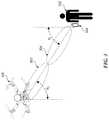
- FIG. 3is a conceptual diagram of an example system for estimating the position and/or orientation of a UAV using a network of phased array wireless transceivers;
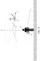
- FIG. 4is a conceptual diagram of an example system for passive localization of a subject tracked by a UAV
- FIGS. 5A-5Billustrate example techniques for estimating the position and/or orientation of objects using images captured by a UAV
- FIG. 6shows an example arrangement of image capture devices coupled to a UAV
- FIG. 7Aillustrates an example technique for defining the motion of a UAV relative to a point of reference using a cylindrical polar coordinate system
- FIG. 7Billustrates an example technique for defining the motion of a UAV relative to a point of reference using a spherical polar coordinate system
- FIG. 8Aillustrates an example scenario including a UAV in flight through a physical environment while capturing images of a subject
- FIG. 8Bis a flow chart describing an example process for dynamically adjusting image capture of a subject by a UAV
- FIG. 9illustrates an example scenario including a UAV adjusting image capture of a subject to avoid a collision with another object
- FIG. 10illustrates an example scenario including a UAV adjusting image capture to keep a subject in view
- FIG. 11illustrates an example scenario including a UAV adjusting image capture of a subject according to a predefined flight path
- FIG. 12illustrates an example scenario including a UAV adjusting image capture of a subject to avoid backlighting
- FIG. 13is a diagram of an example UAV system
- FIG. 14is a diagram of a computing system.
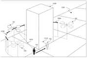
- FIG. 1is an illustration of an unmanned aerial vehicle (“UAV”) 100 operating as an automated aerial platform for capturing images.
- UAV 100may be a rotor-based aircraft (e.g., a “quadcopter”).
- the UAV 100 as shown in FIG. 1may include propulsion and control actuators 110 (e.g. powered rotors or aerodynamics control surfaces) for maintaining controlled flight, sensors for automated navigation and flight control 112 (e.g. an array of multiple image capture devices—described in more detail herein), a gimbaled image capture device 114 for capturing images (including video), other sensors (not shown) (e.g. for capturing audio), and means (not shown) for communicating with other devices (e.g.
- propulsion and control actuators 110e.g. powered rotors or aerodynamics control surfaces
- sensors for automated navigation and flight control 112e.g. an array of multiple image capture devices—described in more detail herein
- a gimbaled image capture device 114for capturing images
- the UAV 100 shown in FIG. 1is according to an example embodiment.
- a UAV 100 in accordance with the present teachingsmay include more or fewer components than as shown.
- An example UAV system that may be part of UAV 100is described later with respect to FIG. 13 .
- UAV 100is shown capturing images of a human subject 102 that in some embodiments may be a user (i.e. in communication with UAV 100 via a mobile device 104 ). However, a communication link with another device (e.g. mobile device 104 ) and control by a human user is not necessary.
- UAV 100may autonomously (i.e. without direct human control) navigate the physical environment, for example by applying a process of visual inertial odometry using images captured by an array of multiple image capture devices. While in autonomous flight, UAV 100 can capture images of one or more subjects in the physical environment using the same array of image capture devices and/or the separate gimbaled image capture device 114 . In this sense, UAV 100 may generally be conceptualized as an autonomous aerial camera rather than as a vehicle with an attached camera, and may therefore represent a paradigm shift in which cameras are understood.
- one or more criteriamay be specified that define how UAV 100 is to respond to given conditions while autonomously capturing images over a physical environment.
- UAV 100may be configured to automatically adjust image capture, which may in some cases include adjusting its flight path.
- image capturemay in some cases include adjusting its flight path.
- criterionstates that while tracking and capturing images of a subject in motion, the UAV 100 is to always (or at least within a threshold tolerance) maintain a clear line of sight with the subject. In other words, it is not enough to stay within a maximum separation distance.
- the UAVmay automatically adjust its flight path to alleviate the obstruction.
- the particular maneuver required in any given situationdepends on the geometric configuration of the subject and the UAV within the physical environment.
- a processing unitlocated on board the UAV or remotely and in communication with the UAV may generate commands configured to adjust image capture, for example, by causing the UAV 100 to reduce altitude below the level of the leaves to alleviate the obstruction in the view.
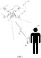
- FIG. 2is a high-level illustration of a localization and navigation system 200 , according to some embodiments, for guiding navigation and image capture by an UAV 100 .
- a relative position and/or orientation of the UAV 100 , and or a relative position and/or orientation of a subject 102may be determined using one or more of the subsystems illustrated in FIG. 2 . It shall be understood that by tracking relative positions and/or orientations over time (continuously or at regular or irregular time intervals (i.e. continually)), the motions (e.g. velocity, acceleration, etc.) of UAV 100 and one or more subjects through a physical environment may be estimated. Accordingly, any systems described herein for determining position and/or orientation may similarly be employed for estimating motion.
- a system 200may include a UAV 100 , a global positioning system (GPS) comprising multiple GPS satellites 202 , a cellular system comprising multiple cellular antennae 204 (with access to sources of localization data 206 ), a Wi-Fi system comprising multiple Wi-Fi routers 208 (with access to sources of localization data 206 ), and a portable multifunction device 104 operated by a user (in this example human subject 102 ).
- GPSglobal positioning system
- a cellular systemcomprising multiple cellular antennae 204 (with access to sources of localization data 206 )
- Wi-Fi systemcomprising multiple Wi-Fi routers 208 (with access to sources of localization data 206 )
- portable multifunction device 104operated by a user (in this example human subject 102 ).
- the UAV 100may comprise components including, but not limited to, an inertial measurement unit (IMU), a GPS receiver, multiple RF receivers and/or transceivers (e.g. cellular LTE, Wi-Fi), and one or more image capture devices.
- IMUinertial measurement unit
- GPS receivere.g. a GPS receiver
- RF receivers and/or transceiverse.g. cellular LTE, Wi-Fi
- image capture devicesmay be used to determine position and/or pose through the use of computer vision techniques and or optics-based collision detection and range finding. This is illustrated conceptually in FIG. 2 by the dotted line 214 .
- Mobile device 104may be any type of portable computing device.
- mobile device 104may include a notebook, a laptop computer, a handheld computer, a palmtop computer, a cell phone, a PDA, a smart phone (e.g., iPhoneTM, etc.), a tablet (e.g., iPadTM, etc), a hand held gaming device (e.g., Sony PSPTM, etc.), a smart watch (e.g., Apple WatchTM, etc.), an augmented reality device (e.g., Google GlassTM, etc.), a virtual reality device (e.g. Oculus RiftTM, etc.) or any other portable computing device.
- mobile device 104may include any of the components described with respect systems 1300 or 1400 as shown in FIGS.
- systemmay refer to a computing system operating as part of and/or in conjunction with any of the computing systems described with respect to FIGS. 13 and 14 .
- methods described hereinmay be performed by a computing system that is not part of UAV 100 or a mobile device 104 , for example a general computing system illustrated with respect to FIG. 14 .
- a relative position and/or orientation of the UAV 100 , a relative position and/or orientation of the subject 102 , and/or a relative position and/or pose of a mobile device 104 operated by a usermay be determined using one or more of the subsystems illustrated in FIG. 2 .
- a position on the globemay be determined for any device comprising a GPS receiver (e.g. the UAV 100 and/or the mobile device 104 ). While GPS by itself in certain implementations may provide highly accurate global positioning it is generally is not capable of providing accurate information regarding orientation. Instead a technique of multiple inputs and multiple outputs (“MIMO”) (as illustrated in FIG. 2 ) may be used for localization, potentially in conjunction with other localization subsystems.
- MIMOmultiple inputs and multiple outputs
- a user(human subject 102 ) is utilizing an autonomous UAV 100 via a mobile device 104 to film herself overhead.
- a relative position and orientation of the UAV 100 relative to the mobile device 104may be necessary.
- a relative position between the UAV 100 and the mobile device 104may be determined using a GPS system to determine a global position of the UAV 100 , a global position of the mobile device 104 and compare the two.
- a position relative to the known locations of antennaemay be determined for both the UAV 100 and mobile device 104 using known positioning techniques.
- Some known positioning techniquesinclude those based on signal trilateration, for example round trip time of arrival (RTT) in which a signal is sent and received by a signal transceiver and distance is calculated based on the elapsed time, received signal strength (RSS) in which the power levels of the transmitted signal and the received signals are analyzed and a distance determined based on a known propagation loss.
- RTTround trip time of arrival
- RSSreceived signal strength
- Other known positioning techniquesinclude those based on signal triangulation, for example angle of arrival (AoA) in which angles of arriving signals are determined and through applied geometry a position determined.
- AoAangle of arrival
- RF signal beamformingi.e. directional signal transmission using phased-shifted antenna arrays
- Beamformingmay be accomplished through the transmission of RF signals at different phases from spatially distributed antennas (a “phased antenna array”) such that constructive interference may occur at certain angles while destructive interference may occur at others, thereby resulting in a targeted directional RF signal field.
- a targeted fieldis illustrated conceptually in FIG. 2 by dotted lines 212 emanating from WiFi routers 210 .
- a UAV 100 and/or mobile device 104may include a phased array of WiFi antenna and a relative position and/or pose may be calculated without the necessity for external existing Wi-Fi routers.
- the UAV 100 and/or mobile device 104may transmit and/or receive a beamformed RF signal via a phased antenna array.
- the UAV 100 and/or mobile device 104may then detect the phase differences and power levels of the respective incoming signals and calculate an AoA for the incoming signals. For example according to FIG. 3 , the mobile device 104 may determine an AoA of ⁇ 1 for the RF signals 302 transmitted by the UAV 100 .
- the UAV 100may determine an AoA of ⁇ 2 for the RF signals 304 transmitted by the mobile device 104 .
- This AoA informationmay then be incorporated with information gathered by an IMU on the UAV 100 and/or mobile device 104 (as well as other positioning data as described earlier) in order to infer a relative position and/or orientation between the UAV 100 and the mobile device 104 .
- an array of Wi-Fi transmitters and signal monitorsmay be utilized for device-free passive localization of objects that are not transmitting signals (e.g. a human subject not carrying a mobile device).
- FIG. 4illustrates an example system 400 for device-free passive localization of subject (e.g. a human subject 102 ).
- a human subject 102passes through a network of Wi-Fi transmitters 408 transmitting RF signals.
- the signal monitors 410e.g. standard wireless sniffers
- Such changes in the RF signal fieldmay be correlated to the presence of the subject 102 , its type, its orientation and its location. Also according to FIG. 4 , information gathered by device-free passive localization system 400 may be fed wirelessly (e.g. via Wi-Fi connection 430 ) for to a nearby UAV 100 in order to inform its tracking of the human subject 102 .
- an inertial measurement unitmay be used to determine relative position and/or orientation.
- An IMUis a device that measures a vehicle's angular velocity and linear acceleration. These measurements can be fused with other sources of information (e.g. those discussed above) to accurately infer velocity, orientation, and sensor calibrations.
- a UAV 100 and/or mobile device 104may include one or more IMUS.
- Using a method commonly referred to as “dead reckoning” an IMU (or associated systems)may calculate and track a predicted a current position based on a previously known position(s) using measured accelerations and the time elapsed from the previously known position(s).
- an embodiment utilizing localization using an IMUmay include localization data from other sources (e.g. the GPS, Wi-Fi, and cellular systems described above) to continually update the last known position and/or orientation of the object.
- a nonlinear estimation algorithmone embodiment being an “extended Kalman filter” may be applied to a series of measured positions and/or orientations to produce a real-time optimized prediction of the current position and/or orientation based on assumed uncertainties in the observed data. Kalman filters are commonly applied in the area of aircraft navigation, guidance, and controls.
- a UAV 100may include an image capture device and computer vision capabilities.
- UAV 100may be programmed to track a user 102 (or other physical object).
- a UAV 100may recognize the captured image as the subject and may use the recognition information to perform aerial maneuvers by the UAV 100 to keep the subject in view, and/or may make adjustments to an image stabilization system (e.g. a gimbaled image capture device) to keep the subject in view.
- an image stabilization systeme.g. a gimbaled image capture device
- Relative position and/or orientationmay be determined through computer vision using a number of methods.
- raw image data received from one or more image capture devicesmay be received and processed to correct for certain variables (e.g. differences in camera orientation and/or intrinsic parameters (e.g. lens variations)).
- an image capture device of the UAV 100may include two or more cameras, for example an array of multiple cameras that provide an unobstructed view around the UAV 100 . By comparing the captured image from two or more vantage points (e.g.
- a system employing computer visionmay calculate estimates for the relative position and/or orientation of the vehicle on which the image capture device is mounted (e.g. UAV 100 ) and/or of a captured object in the physical environment (e.g. the subject).
- the calculated position and/or orientation data for the UAV 100e.g., data from GPS, WiFi, Cellular, and/or IMU, as discussed above
- a relative position and/or orientationmay be determined between the UAV 100 and the captured physical object.
- an image capture device of UAV 100may be a single camera (i.e. a non-stereoscopic camera).
- computer vision algorithmsmay identify the presence of an object and identify the object as belonging to a known type with particular dimensions.
- an objectmay be identified by comparing the captured image to stored two-dimensional (2D) and/or three dimensional (3D) appearance models.
- the subject 102may be identified as an adult male human.
- the 2D and/or 3D appearance modelsmay be represented as a trained neural network that utilizes deep learning to classify objects in images according to detected patterns With this recognition data, as well as other position and/or orientation data for the UAV 100 (e.g. data from GPS, WiFi, Cellular, and/or IMU, as discussed above), UAV 100 may estimate a relative position and/or orientation of the subject 102 .
- FIG. 5Ashows a simplified diagram that illustrates how sensor data gathered by an IMU at a mobile device 104 may be applied to sensor data gathered by an image capture device at UAV 100 to determine position and/or orientation data of a physical object (e.g. a user 102 ).
- Outline 550represents the 2-dimensional image captured field of view at UAV 100 . As shown in FIG.
- the field of viewincludes the image of a physical object (here user 102 ) moving from one position to another.
- UAV 100may determine a distance A traveled across the image capture field of view.
- the mobile device 104carried by user 102 , may determine an actual distance B traveled by the user 102 based on measurements by internal sensors (e.g. the IMU) and an elapsed time.
- the UAV 100may then receive the sensor data and/or the distance B calculation from mobile device 104 (e.g., via wireless RF signal). Correlating the difference between the observed distance A and the received distance B, UAV 100 may determine a distance D between UAV 100 and the physical object (user 102 ).
- a relative position and/or orientationmay be determined between the UAV 100 and the physical object (e.g. user 102 ).
- FIG. 5Billustrates the working concept behind visual odometry at a high level. A plurality of images are captured in sequence as an image capture device moves through space. Due to the movement of the camera, the images captured of the surrounding space change from frame to frame. In FIG. 5B , this is illustrated by initial image capture field of view 552 and a subsequent image capture field of view 554 captured as the camera has moved from a first position and orientation to a second position and orientation over an elapsed time.
- the cameramay capture real world physical objects, for example, the house 580 and/or the human subject 102 .
- Computer vision techniquesare applied to the sequence of images to detect and match features of physical objects captured in the field of view of the camera.
- a system employing computer visionmay search for correspondences in the pixels of digital images that have overlapping fields of view (FOV).
- the correspondencesmay be identified using a number of different methods such as correlation-based and feature-based methods.
- featuressuch as the head of a human subject 102 or the corner of the chimney on the house 580 can be identified, matched, and thereby tracked.
- estimationsmay be made for the position and/or orientation of the camera over time. Further, theses estimates can be used to calibrate the localization systems, for example through estimating differences in camera orientation and/or intrinsic parameters (e.g. lens variations)) or IMU biases and/or orientation. Visual inertial odometry may be applied at both the UAV 100 and mobile device 104 to calculate the position and/or orientation of both systems. Further, by communicating the estimates between the systems (e.g. via a Wi-Fi connection) estimates may be calculated for the respective positions and/or orientations relative to each other.
- IMUor accelerometer(s) or gyroscope(s)
- position, orientation, and motion estimation based in part on sensor data from an on board IMUmay introduce error propagation issues.
- optimization techniquesmay be applied to position, orientation, and motion estimations to counter such uncertainties.
- a nonlinear estimation algorithmone embodiment being an “extended Kalman filter”
- Such estimation algorithmscan be similarly applied to produce smooth motion estimations.
- systems in accordance with the present teachingsmay simultaneously generate a 3D map of the surrounding physical environment while estimating the relative positions and/or orientations of the UAV 100 and/or subject within the physical environment.
- Thisis sometimes referred to simultaneous localization and mapping (“SLAM”).
- SLAMsimultaneous localization and mapping
- a system in accordance with the present teachingcan search for dense correspondence between images with overlapping FOV (e.g. images taken during sequential time steps and/or stereoscopic images taken at the same timestep). The system can then use the dense correspondences to estimate a depth or distance to each pixel represented in each image. These depth estimates can then be used to continually update a generated 3D model of the physical environment taking into account motion estimates for the image capture device (i.e. UAV 100 ) through the physical environment.
- computer visionmay include sensing technologies other than image capture devices (i.e. cameras) such as laser illuminated detection and ranging (LIDAR or Lidar).
- LIDARlaser illuminated detection and ranging
- a UAV 100 equipped with LIDARmay emit one or more laser beams in a continuous scan up to 360 degrees around the UAV 100 .
- Light received by the UAV 100 as the laser beamsreflect off physical objects in the surrounding physical world may be analyzed to construct a real time 3D computer model of the surrounding physical world.
- Depth sensing through the use of LIDARmay in some embodiments augment depth sensing through pixel correspondence as described earlier.
- Such 3D modelsmay be analyzed to identify particular physical objects (e.g. subject 102 ) in the physical environment for tracking.
- images captured by camerase.g., as described earlier
- images captured by camerasmay be combined with the laser constructed 3D models to form textured 3D models that may be further analyzed in real time or near real time for physical object recognition (e.g. by using computer vision algorithms
- the computer vision-aided localization and navigation system described abovemay calculate the position and/or pose of features in the physical world in addition to the position and/or pose of the UAV 100 and/or mobile device 104 .
- the position of these featuresmay then be fed into the navigation system such that motion trajectories may be planned that avoid obstacles.
- the visual navigation algorithmsmay incorporate data from proximity sensors (e.g. electromagnetic, acoustic, and/or optics based) to estimate obstacle position with more accuracy. Further refinement may be possible with the use of stereoscopic computer vision with multiple cameras, as described earlier.
- the previously described relative position and/or orientation calculationsmay be performed by a UAV 100 , mobile device 104 , other remote computing device(s) (not shown in the figures), or any combination thereof.
- the localization system 200 of FIG. 2(including all of the associated subsystems as previously described) is only one example of a system for localization and navigation. Localization system 200 may have more or fewer components than shown, may combine two or more components, or a may have a different configuration or arrangement of the components. Some of the various components shown in FIGS. 2 through 4 may be implemented in hardware, software or a combination of both hardware and software, including one or more signal processing and/or application specific integrated circuits.
- UAV 100may comprise multiple high resolution image capture devices 602 (e.g. cameras) with spatial offsets from each other, thereby providing the capability to capture an unobstructed view of the physical environment surrounding UAV 100 .
- image capture devices 602may be arranged to provide a full 360 degree view around UAV 100 , as illustrated in FIG. 6 . However, a full 360 degree view may not be necessary in all embodiments.
- the image capture devices 602may be arranged such that at least two cameras are provided with overlapping fields of view, thereby allowing for stereoscopic (i.e. 3D) image/video capture and depth recovery (e.g. through computer vision algorithms) at multiple angles around UAV 100 .
- FIG. 6shows a high-level illustration of the concept of multiple image capture devices 602 mounted to UAV 100 with overlapping fields of view as represented by the dotted lines.
- FIG. 6is provided to illustrate the concept, but does not indicate a particular configuration or geometry as a limitation.
- a UAV in accordance with the present teachingsmay include more or fewer image capture devices 602 .
- the individual fields of view of any given image capture devicemay be expanded through the use of a “fisheye” lens, thereby reducing the total number of image capture devices needed to provide a 360 degree view around UAV 100 .
- each cameramay be calibrated to an onboard inertial measurement unit (IMU) by fusing data from the cameras and IMUs in a visual inertial odometry framework.
- IMUinertial measurement unit
- a monocular navigation algorithmmay be run for each camera paired with an on-board IMU and as the relative position and orientation calibration is dialed in, stereo correspondence may be performed on observed primitives representing a pair of corresponding image features captured by a pair of cameras in order to provide a more robust estimation of distance to the objects.
- UAV 100includes an image capture adjustment and stabilization system. Capturing images (including video) from a vehicle in motion (such as from a UAV 100 ) may lead to quality issues such as blur, shake, and disorientation. Image stabilization may generally refer to techniques used to counter these effects and produce a clear stable image even when captured by a vehicle in motion.
- a multi-axis mechanical gimbal devicemay, through the use of gyroscopes and mechanical actuators along two or more axis, physically stabilize an image capturing device (e.g. a camera) coupled to a mobile platform.
- An example of a multi-axis gimbal currently availableis the Freefly MoVI®.
- multi-axis mechanical gimbalsmay add significant mechanical and systems complexity as well as weight to a UAV 100 .
- captured digital imagesmay be digitally “stabilized” using digital image processing to manipulate the image.
- Parrotoffers a drone with a motionless 180 degree camera with a fisheye lens.
- Using post processing and crop filtersmay result in a “stabilized” image.
- full digital image stabilizationmay reduce image quality due to image sensor resolution limits, and in the case of using crop filters may require capturing more data than is necessary.
- a UAV 100may include a hybrid approach comprising mechanical gimbals providing freedom of motion along one or more axes along with real-time image processing (herein referred to as a “digital gimbal”).
- a single axis mechanical gimbalcapable of adjusting the orientation of an image capture device in conjunction with the yaw control of the UAV 100 and digital image processing may produce a full range or image capture from looking straight down from the UAV 100 to the ground to looking straight up from the UAV 100 to the sky while minimizing the mechanical complexity of the stabilization system.
- a single axis mechanical gimbalwould adjust the pitch of the image capture device. Adjusting pitch as opposed to roll or yaw, would allow for overall camera range of motion where the UAV 100 is implemented as a rotary vehicle, for example a quadcopter (see e.g. discussion in section titled “Unmanned Aerial Vehicle—Example System” for additional information). This has to do with the way in which the flight of a quadcopter is controlled. Generally, a quadcopter is controlled by varying the orientation of its vertical axis. In other words, in a hover the quadcopter's vertical axis is perpendicular to the ground.
- utilizing a pitch gimbalgives maximum possible view range of motion since the yaw of the image capture device is easily controlled by adjusting the yaw of the quadcopter itself and the roll of the image capture device is easily controlled through digital image processing, for example simple image rotation transforms.
- the hybrid mechanical digital gimbal system described abovehas been described with a single axis mechanical gimbal, however it shall be appreciated that a hybrid mechanical digital gimbal system for image stabilization and tracking may include mechanical actuation on more than one axis.
- a mechanical gimbalis utilized to adjust the pitch and roll of an on-board image capture device with adjustments in yaw accomplished by digitally processing the captured images.
- the UAV 100may maneuver according to an absolute fixed coordinate system.
- user inputs and gesturesmay correspond with an instruction to move to an absolute point in space.
- the UAV 100may also maneuver according to a coordinate system relative to a “point of reference.”
- the point of referencemay be defined as at or associated with a physical object in the physical environment, for example a human subject 102 and/or a mobile device 104 through which a user (in this case human subject 102 ) may provide control input.
- the point of referencemay also be another point in space which may be specified via the mobile device 104 by clicking on a location of interest on a map or image.
- a user 102 viewing a live video feed from UAV 100 through a touch display of mobile device 104may touch a point or select a displayed object to redefine the point of reference about which motion is defined.
- the defined point of referencemay be stationary (e.g. a building or physical marker) or may be in motion (for example a moving car).
- any motions by the UAV 100may be made relative to the car.
- the point of referenceis set to be a car moving at 25 mph, then a UAV 100 in “hover” would actually match the speed of the car while maintaining a constant position/orientation relative to the car.
- a particular point of referencecan be tracked using any of the aforementioned systems for localization and navigation. Specifically, in an embodiment, a point of reference can be tracked in a 3D map of the surrounding environment generated using visual inertial odometry with captured stereoscopic images of the surrounding environment.
- a relative coordinate systemmay simplify the motion calculations necessary to maneuver the UAV 100 . Further, controlled motions made relative to point of reference associated with a subject 102 or mobile device 104 may allow for more intuitive control of the UAV 100 .
- FIGS. 7A-7BIllustrate at a high level how the motion of a UAV 100 may be estimated and/or defined according to different coordinate systems.
- the motion of an UAV 100may be estimated and/or defined according to a cylindrical polar coordinate system relative to a point of reference, for example human subject 102 or a mobile device 104 held operated by a user (in this example human subject 102 ).
- a position (and thereby motion) relative to a point of referencemay be defined according to the cylindrical polar coordinate system.
- the position of UAV 100may be defined at a coordinate (r, 0 , z) relative to a point of reference (in this example human subject 102 ).
- generated control commandsmay cause the UAV 100 to move along the normal tangent to an axial direction z.
- a control commandmay cause the UAV 100 to accelerate along basis directions êz and ê ⁇ , with no acceleration in the basis direction êr.
- UAV 100may travel along an invisible cylinder at a constant radius R from user 102 .
- control commandsmay cause UAV 100 to accelerate along basis direction er while maintaining constant positions z and ⁇ .
- the motion of an UAV 100may be estimated and/or defined according to a spherical polar coordinate system relative to a point of reference, for example human subject 102 or a mobile device 104 held operated by a user (in this example human subject 102 ). Similar to the example illustrated in FIG. 7A , at any given time, the position of UAV 100 may be defined at a coordinate (r, ⁇ , ⁇ ) relative to a point of reference (in this example human subject 102 ). Further, in some embodiments, in order to maintain a constant separation with the point of reference, generated control commands may cause the UAV 100 to move along basis directions ê ⁇ and ê ⁇ , with no acceleration in basis direction er.
- UAV 100may travel along an invisible spherical plane at a constant radius R from a point of reference (e.g. human subject 102 ). Also similarly, in order to close separation, control commands may cause UAV 100 to accelerate along basis direction er.
- Calculations for the motion of the UAV 100 in the above described control configurationsmay be accomplished using relative or absolute coordinate system of any type (Cartesian, polar, cylindrical, etc.), although motion calculations based on an absolute coordinate system may be more processor intensive than if made relative to point of reference (e.g. human subject 102 or mobile device 104 ).
- point of referencee.g. human subject 102 or mobile device 104
- the cylindrical and polar coordinate systemsare used here for illustrative purposes to describe more clearly the way in which the UAV 100 may move relative to a reference point (e.g. the human subject 102 or mobile device 104 ) using the above described techniques.
- calculation of maneuvers to be performed by the UAV 100may include implementation of a feed-forward control scheme. For example, as the motion of UAV 100 is continually estimated relative to a subject in motion and an obstacle is detected that will impede a planned path of the UAV 100 , the planned path may be continually updated in order to avoid the obstacle. This will allow for smoother transitions between flight maneuvers.
- the UAV 100may capture images and or video using one or more on board image capture devices (e.g. and image capture device mounted to a hybrid mechanical-digital gimbal).
- image capturemay track the same point of reference used for calculating motion (e.g. a human subject 102 ).
- the UAV 100may maneuver around the human subject 102 in response to generated control commands.
- the UAV 100may adjust the orientation and/or processing of image capture device(s) (e.g. cameras) such that the point of reference (i.e.
- Image capturemay be adjusted according to techniques previously described, for example, by using a mechanical and/or a hybrid mechanical-digital gimbal system linked to one or more image capture devices.
- FIG. 8Aillustrates an UAV 100 in autonomous flight through a physical environment 802 that may dynamically adjust image capture of a subject (e.g. human subject 102 ) to satisfy a specified criterion related to a quality of image capture.
- a subjecte.g. human subject 102
- UAV 100is at current position/orientation (indicated by the solid line drawing of a quadcopter) and is in autonomous flight along a current planned flight path 804 towards a future position/orientation (indicated by the dotted line drawing of the quadcopter). While in flight, UAV may be capturing images (including video) of a subject in the physical environment. In the example shown in FIG. 8 , UAV 100 is capturing images of human subject 102 as indicated by the image capture field of view 810 . The subject 102 may also be in motion through the physical environment.
- human subject 102is shown at a current position/orientation (indicated by the solid drawing of a human subject) and is in motion towards a future position/orientation (indicated by the dotted line drawing of a human subject).
- image capture of the subjectmay be by one or more image capture devices (e.g. cameras) mounted to UAV 100 .
- the image capture device(s)may be mounted to a motorized gimbal to enable visual stabilization and/or tracking.
- the motorized gimbalmay be part of a hybrid mechanical-digital gimbal system.
- FIG. 8Bis flow chart of an example process 800 b for adjusting image capture by a UAV 100 to satisfy a specified criterion.
- Process 800 bbegins at steps 802 b and 804 b with estimating a motion of the UAV 100 in autonomous flight through a physical environment 820 and estimating a motion of a subject through the physical environment 820 .
- the motion of UAV 100 and subject 102may be estimated using any of the previously described techniques.
- the motions of the UAV 100 and/or subject 102is estimated based in part on images captured by an image capture device associated with UAV 100 .
- the image capture device of UAV 100may include an array of multiple image capture device (e.g.
- the motions of UAV 100 and/or subject 102may be estimated using a process of visual inertial odometry by combining the captured images with sensor data from one or more inertial measurement units (IMU) onboard the UAV 100 and/or a mobile device 104 held by a human subject 102 .
- IMUinertial measurement units
- the process of estimating motionsmay include estimating and tracking position/orientation of the UAV 100 and/or subject 102 over time. Further, it shall be understood that at any given point in time the UAV and or subject may be stationary (i.e. the estimated motion may effectively be zero).
- Process 800 bcontinues at step 806 b with in response to estimating the motions of the UAV 100 and the subject 102 , generating control commands to dynamically adjust image capture of the subject 102 by the image capture device associated with the UAV 100 to satisfy a specified criterion related to a quality of the image capture.
- control commandsare generated by a flight controller onboard the UAV 100 (for example flight controller 1308 described with respect to FIG. 13 ).
- the control commandsmay be generated by a remote computing device (e.g. a mobile device 104 or any other network-connected computing device) and transmitted to the UAV 100 via a wireless communication link (e.g. WiFi).
- the one or more specified criteriamay be stored as instructions on a memory unit onboard the UAV 100 and/or in a remote computing device (e.g. a mobile device 104 ).
- the dynamic adjustment of image capturemay include adjusting the characteristics or settings of an image capture device associated with UAV 100 , adjusting the orientation of an image capture device associated with UAV 100 , adjusting image processing (in real time or post processing), and or adjusting the motion of UAV 100 through the physical environment.
- the control commands to dynamically adjust image capturemay include control commands to adjust any of focus, aperture, shutter speed, light sensitivity (ISO), frame rate, color balance, image framing, or image stabilization by an image capture device associated with UAV 100 .
- ISOlight sensitivity
- control commands to dynamically adjust image capturemay include control commands to adjust subject tracking and image stabilization using an image capture device mounted to a motorized gimbal, for example a hybrid mechanical-digital gimbal.
- control commands to dynamically adjust image capturemay include control commands to adjust the position and/or orientation of UAV 100 .
- dynamicor “dynamically” in this context imply that adjustments are made continually or near continuously as additional data is gathered (e.g. via an array of image capture devices mounted to UAV 100 ).
- the subject's motionmay continually change, physical objects in the surrounding physical environment may be in motion and present obstacles, characteristics of the physical environment (e.g. weather, lighting, etc.) may change, and or the system may receive direct control inputs from a user.
- motion(of the UAV 100 and subject 102 ) is estimated and a planned flight path and image capture setting for UAV 100 is updated at period time increments in response to new data gathered by one or more sensors (e.g. image capture devices) associated with UAV 100 . These increments may be static (e.g.
- detected changes in the surrounding environmentmay cue a navigation/localization system to narrow the periodic increments at which motion estimations and image capture adjustments are made to more accurately respond to such changes in the surrounding environment.
- a navigation/localization systemmay expand the periodic increments at which motion estimations and image capture adjustments are made so as to conserve power and/or data processing resources.
- a system in accordance with the present teachingsmay incorporate additional data when generating control commands to adjust image capture by an UAV 100 .
- the generated control commandsmay further be based on data such as the geographical location of UAV 100 at the time of capture, the date and time images are captured, etc.
- a system in accordance with the present teachingsmay determine (using any of the aforementioned systems for localization) that UAV 100 is capturing images outdoors in the northern hemisphere in the evening during a summer month and may, accordingly adjust generated control commands to better suit those conditions.
- a system in accordance with the present teachingsmay incorporate data gathered from other sensors associated with UAV 100 .
- an ambient light sensormay gather data that may directly inform a level of ambient light in the physical environment without the need for additional processing of captured images.
- a computing systemmay generate control commands to dynamically adjust image capture to satisfy a specified criterion related to a quality of the image capture.
- a specified criterionrelated to a quality of the image capture.
- the quality of image capture in any given situationcan depend on a number of different factors. For example, if the image capture is of a particular subject (e.g. a human, an animal, a vehicle, a building, or any other object), a basic determination on the quality of image capture may be whether the subject remains in view, in focus, properly framed, etc.
- a system in accordance with the present teachingmay automatically generate control commands configured to dynamically adjust image capture by a UAV 100 to meet those specified one or more criteria without any direct control input by a user (e.g. remote control).
- the specified one or more criteriamay be based on subjective and/or objective image capture quality standards.
- a common objective standard for determining a quality of image captureis the balance of tonal distribution within the captured image.
- Such distributioncan be graphically represented in the form of an image histogram.
- the horizontal axis of the graphrepresents a range of tonal distribution, while the vertical axis represents the number of pixels at that particular tone.
- What resultsis a chart conveying information regarding the tonal variation in a given set of image data. For example, an image histogram, having most of its data points on the left side, may indicate a dark underexposed image.
- an image histogram in which most of the data points fall on the right sidemay indicate a bright and perhaps overexposed image.
- a more balanced image histogrammay therefore indicate a spread of tonal variation indicating greater contrast and therefore a higher quality image.
- the above exampleserves only to illustrate that the quality of an image may be based at least in part on certain objective criteria.
- Some other example of objective standardsmay be based on the variation in motion of a given shot indicating a steady or unsteady capture, balance of colors in a given shot, color saturation, variation in luminance within a given shot perhaps indicating an optimal or sub-optimal lighting source configuration (e.g. a shot of a subject individual with the sun at their back), focus of the shot, optical flow or any other standards tending to indicate an objective quality of a captured image.
- the specified one or more criteriamay be based on subjective image capture quality standards.
- subjective image quality standardsmay be based at least in part on polling and/or statistical methods applied to historical data to arrive at subjective standards that approximate generally held views of image quality.
- based on historical datae.g. user reviews of sets of captured images
- it may be determined that framing a subject within a shot according to the so called “golden ratio”i.e. 1 to 1.618
- a criterionmay be specified that is related to this golden ratio-based subjective standard of image quality.
- a system in accordance with the present teachingsmay generate control commands configured to adjust image capture (including maneuvering the UAV 100 relative to subject 102 ) so as to achieve a composition roughly in line with the golden ratio thereby satisfying the specified criterion.
- subjective image quality standardsmay be based on existing statistical data. For example a poll may be held in advance amongst a set of leading cinematographers or photographers. Their subjective input into the components of a high quality image may then inform the standards upon which the one or more criteria are based. Such an implementation would in essence place a virtual expert cinematographer/photographer in control of the image capture capabilities of an UAV 100 .
- subjective image quality standardsmay be based on continually gathered data associated with image quality and thereby continually evolve, for example by using machine learning algorithms.
- multiple UAVs located around the worldmay capture images that are then uploaded to a third party social networking platform.
- the multiple users, forming a community on the social networking platformmay view each other's uploaded images and provide feedback (e.g. in the form of comments, upvotes, likes, etc.).
- Such a systemmay then aggregate the community feedback data with analyses of the uploaded images/video in order to inform and adjust the specified one or more criteria by which image capture adjustments are made for a given UAV 100 .
- machine learning algorithmsmay be applied to the gathered community feedback data to define certain subjective image quality standards.
- an objective image capture quality standardmay be (as previously described) to keep the subject in the field of view and in focus.
- a UAV 100 at a current position(as indicated by solid line quadcopter) is in autonomous flight a human subject 102 located in a physical environment 820 . Both UAV 100 and human subject 102 may be in motion or stationary.
- the specified criterion in this contextmay simply be to keep the human subject 102 in view of an image capture device of UAV 100 .
- the specified criterionitself may include certain rules that must be met (within tolerance) to satisfy the criterion.
- criterionmay be met as long as the image capture device captures the subject while the UAV 100 is no more than 100 meters from the subject.
- set tolerancesmay define permissible limits non-adherence to these rules.
- a set tolerancemay be based on a temporal aspect (e.g. the subject 102 can fall out of view for no more than 2 seconds).
- a systeme.g. a flight controller
- human subject 102is in motion to a future location (as indicated by the dotted line human subject).
- the control commands configured to keep the subject in viewmay include control commands to autonomously fly along a planned flight path 804 .
- planned flight path 804represents an instantaneous planned flight path given the current sensor data available.
- this planned flight pathmay be adjusted (e.g. based on changes in the motion of the UAV 100 and/or subject 102 or the introduction of another physical obstacle) to satisfy the specified criterion of keeping the subject 102 in view.
- motion planning for travel along a planned flight pathmay involve a technique generally referred to as “feed-forward” control.
- control commandsmay be generated (and continually updated) in anticipation of maneuvers needed to maintain autonomous flight along the current planned flight path.
- a system in accordance with the present teachingsmay generate control commands that anticipate the various maneuvers needed to fly along the sweeping arc of flight path 804 and decelerate to arrive at a stopping position (e.g. future position indicated by the dotted line quadcopter).
- planned flight path 804represents the current planned flight path at a given time.
- the planned flight path 804may be continually adjusted (or at least adjusted at time intervals) to adjust image capture to satisfy a specified criterion.
- control commandsmay have multiple options for dynamically adjusting image capture by the UAV 100 to meet the specified criterion.
- control commandsmay be generated that cause UAV 100 to simply follow human subject 102 at a constant distance (or at least within a maximum separation distance) while maintaining a constant altitude (or at least above a minimum altitude).
- control commandsmay be generated that cause UAV 100 to fly past human subject 102 while an image capture device configured for active tracking (e.g. using a hybrid mechanical-digital gimbal) is adjusted to keeps the subject 102 in the field of view 810 , as illustrated in FIG. 8A .
- the specified one or more criteriamay include further constraints.
- FIG. 9shows an example scenario involving a UAV 100 in flight over a physical environment 920 and capturing images of a human subject 102 .
- UAV 100may be in autonomous flight along a current planned flight path 904 to maneuver to avoid a collision with another object 930 in the physical environment while keeping human subject 102 in view (as indicated by field of view lines 910 .
- the example illustrated in FIG. 9is idealized and shows a relatively large stationary object 930 (for example a building or other structure), but the same concepts may apply to avoid smaller mobile objects such as a bird in flight.
- FIG. 9shows an example scenario involving a UAV 100 in flight over a physical environment 920 and capturing images of a human subject 102 .
- UAV 100may be in autonomous flight along a current planned flight path 904 to maneuver to avoid a collision with another object 930 in the physical environment while keeping human subject 102 in view (as indicated by field of view lines 910 .
- the example illustrated in FIG. 9is idealized and shows a relatively
- a system in accordance with the present teachingsmay generate control commands to dynamically adjust image capture includes by generating control commands to maneuver UAV 100 along flight path 904 to avoid object 930 while keeping human subject in view (as indicated by field of view lines 910 ).
- thisillustrates that the addition of another constraint to the specified criterion (i.e. avoiding a collision) narrows the number of possible flight paths UAV 100 can take while still satisfying the specified criterion.
- UAV 100must also maneuver to the right of object 930 .
- any of the previously described localization techniquesmay be utilized to detect the presence of the object 930 with relation to human subject 102 and/or UAV 100 and to generate control commands configured to cause UAV 100 to avoid a collision with object 930 .
- the geometry and position/orientation of object 930 relative to UAV 100may be determined.
- FIG. 10shows an example scenario involving a UAV 100 in flight over a physical environment 1020 and capturing images of a human subject 102 .
- human subject 102is located on an opposite side of object 1010 from UAV 100 but is within a field of view of UAV 100 as indicated by the line of sight 1010 connecting the solid line UAV 100 to the solid line subject 102 .
- a system in accordance with the present teachingsmay generate control commands configured to adjust image capture to keep subject 102 in view and unobstructed in order to satisfy the specified criterion.
- the generated control commandsmay include control commands configured to cause UAV 100 to maneuver along a flight path 1006 to keep the view of human subject 102 unobstructed.
- the example illustrated in FIG. 10is idealized and shows a relatively simple stationary object 1030 (for example a building or other structure).
- a specified criterion to avoid collision with the objectmay produce the same or similar results as a specified criterion to keep the view unobstructed.
- UAV 100may maintain a maximum separation distance while maneuvering to both avoid a collision with an object and keep the view unobstructed.
- an object having more complex featuressuch as a tree with sparse canopy cover.
- a system in accordance with the present teachingsmay generate control commands configured to cause UAV 100 to fly over the tree while tracking the human subject 102 walking under the tree. Collision is avoided and because the canopy is sparse, the subject 102 remains in view. However, this will still result in poor image capture because the view of the subject 102 will be obstructed by intermittent leaves. Instead, if a criterion is specified to keep the view of the subject unobstructed, the system may instead generate control commands configured to cause UAV 100 to rapidly reduce its altitude to drop below the canopy of the tree and to continue to track human subject 102 . In such an example, UAV 100 may increase its altitude again once human subject 102 has emerged from under the canopy of the tree.
- the estimated motion of UAV 100 and subject 102may be based in part on localization data relative to a computer-generated 3D map. For example if a pre-generated 3D map of the surrounding physical environment is available, the motions of UAV 100 and/or subject 102 relative to the 3D map may be estimated using any of the previously described localization techniques. Alternatively, if a pre-generated 3D map is not available, systems in accordance with the present teachings may continually generate and update a 3D map of the physical environment while the UAV 100 is in flight through the environment through a process sometimes referred to as SLAM (simultaneous localization and mapping). Again, as previously discussed, such a 3D map may be generated using a process of visual inertial odometry based in part on images captured by an image capture device associated with UAV 100 .
- SLAMsimultaneous localization and mapping
- a system in accordance with the present teachingmay define, within the 3D map, a virtual line between a virtual representation of an estimated position of the subject 102 and a virtual representation of an estimated position of the UAV 100 .
- the systemmay generate control commands configured to cause UAV 100 to fly a path such that the virtual line does no not intersect a virtual representation of another physical object.
- this criterionmay be specified with a certain tolerance to account for objects in motion.
- Sight line 1010may represent the virtual line connecting the representations of UAV 100 and subject 102 within a virtual environment (i.e. representative of physical environment 1020 ). As human subject 102 begins to move within the physical environment (as shown by the arrow in FIG. 10 ), the virtual line 100 connecting the virtual representations moves as well.
- the virtual line 1010 within the 3D mapintersects the corner of a virtual representation of physical object 1030 .
- This intersectionthereby causes the system to generate control commands configured to cause UAV 100 to maneuver to avoid the intersection.
- the motion of the virtual linecan be tracked and it may be determined that in order to avoid the intersection, UAV 100 should maneuver along flight path 1006 as opposed to flight path 1004 to keep the view of subject 102 unobstructed.
- the generated 3D mapmay be a voxel map configured to approximate the more complex objects in the physical environment.
- virtual representation of the treemay include a number of virtual volumetric elements (i.e. voxels) representing the branches and leaves.
- the virtual linemay intersect with multiple virtual representations of objects, particularly in real world situations with multiple complex objects populating the physical environment.
- multiple points of intersectioncan be detected along the virtual line at a given time.
- a flight pathcan be calculated to avoid visual obstruction by the multiple intersecting objects.
- This flight pathcan be relatively simple (for example similar to the arc of flight path 1006 ) to avoid clusters of multiple objects (e.g. the leaves forming the canopy cover of a tree) or may include multiple complex maneuver intended to avoid visual obstruction caused by the multiple objects indicated by the multiple intersection points (e.g. multiple trees between a UAV 100 and subject 102 ).
- intersection points along a virtual linecan be analyzed differently depending on their distance from UAV 100 .
- Motion by a UAV 100generally has a greater impact on resolving visual obstruction caused by objects that are closer to the UAV 100 . This of course depends on the size and/or shape of the obstructing object, however in general relatively minor maneuvers by UAV 100 may be sufficient to maintain line of sight with a subject around an object that is close to UAV 100 . Conversely, more drastic maneuvers by UAV 100 may be necessary to maintain line of sight around an object that is closer to subject 102 . This makes sense when again considering the scenario described in FIG. 10 .
- the virtual representation of object 1030can also be described as multiple surfaces that intersect the virtual line at multiple points.
- obstructed line of sight line 1012intersects a first surface of object 1030 that faces UAV 100 at a first point and a second surface of object 1030 that faces a future position of subject 102 at a second point.
- a minor maneuver along flight path 1006may be sufficient such that sight line 1012 no longer intersects the first surface (i.e. the surface closest to UAV 100 ) at the first point.
- a more extended maneuver along flight path 1006may be necessary before sight line 1012 no longer intersects the second surface (i.e. the surface closest to subject 102 ) at the second point, thereby establishing line of sight with subject 102 .
- a specified criterion(e.g. to maintain line of sight with a subject) can be applied or combined with inputs by a user. For example, consider a human user operating controlling UAV 100 using a device 104 . The user inputs control commands via device 104 that are transmitted to UAV 100 causing it to maneuver through the physical environment in much the same way a remote control system operates. However, a control criterion may be specified and applied to any input control commands to maintain line of sight with a subject 102 (e.g. the user). In other words, UAV 100 may maneuver according to the user's direct control commands but may adjust certain maneuvers to maintain line of sight with a subject despite these control commands.
- the specified criterioncan be applied to modify direct control commands from a user.
- user inputscan be combined with motion estimations of the UAV 100 and/or subject 102 to generate control commands that closely approximate maneuvers intended by the user input while satisfying a given specified criterion (e.g. line of sight).
- This application of specified criterion such as maintaining line of sight to user inputscan be particularly useful where certain flight regulations are enforced.
- the Federal Aviation Administration (FAA) and Department of Transportation (DOT)are currently in the process of finalizing flight regulations applicable to certain UAVs that require that a remote operator (i.e. a user) maintain visual contact with the UAV at all times.
- a simple control restraint on separation distancemay be helpful to an extent in enforcing a line of sight regulation.
- a UAVcan be configured so that it is never outside a maximum separation distance from an associated control device.
- such a constraintwill not account for situations in which line of sight is obstructed by objects within the maximum separation distance. Instead, using the aforementioned techniques, line of sight regulations may be more effectively and automatically enforced.
- a criterionmay be specified to adjust image capture according to a predefined script to suit a particular type of scene being captured.
- a systemin response to the determined motions of the UAV 100 and subject 102 , a system may generate control commands configured to cause the UAV 100 to fly a pre-scripted flight path and/or capture images using predefined settings.
- the pre-scripted flight path and/or image capture settingsmay be based on one or more objective and/or subject image quality standards. As an illustrative example, it may be subjectively desirable to perform certain pre-scripted flyover shots where the subject being captured is part of a scene with a high level of action.
- a UAV 100is in autonomous flight over a physical environment 1120 while tracking and capturing images of a human subject 102 .
- human subject 102is shown as a skier traveling down a mountainside.
- control commandsmay be generated that include control commands configured to cause UAV 100 to fly pre-scripted flyover path 1104 over human subject 102 to capture subjectively high quality action-based video of human subject 102 .
- adjustments in image capturemay be made dynamically in response to the changing motions of UAV 100 and/or subject 102 .
- FIG. 11a UAV 100 is in autonomous flight over a physical environment 1120 while tracking and capturing images of a human subject 102 .
- human subject 102is shown as a skier traveling down a mountainside.
- control commandsmay be generated that include control commands configured to cause UAV 100 to fly pre-scripted flyover path 1104 over human subject 102 to capture subjectively high quality action-based video of human subject 102 .
- adjustments in image capturemay be made dynamically in response to the
- control commandsmay be generated that are configured to cause UAV 100 to fly an alternative pre-scripted flight path (not shown). For example, in order to capture the action of the mid-air maneuver by the human subject 102 , control commands may be generated to cause UAV 102 to quickly fly under subject 102 while tracking image capture of subject 102 .
- control commandsmay be generated that adjust certain characteristics or settings of the image capture device to deliver subjectively higher quality image capture.
- subjective image quality standards for capturing downhill skiing scenesmay dictate that the image capture device be set to, for example, a certain focal length, shutter speed, white balance, exposure, etc.
- a system in accordance with the present teachingsmay automatically determine (based in part on those estimated motions) the type of scene being captured. For example, a process for determining the type of scene being captured may include first identifying the subject 102 in the physical environment.
- the subject 102is described as a general object (human or otherwise) that is the focus of image capture by UAV 100 . Tracking of a subject 102 may require differentiating the subject as a discrete object apart from its surroundings, but does not necessarily require identifying what the subject 102 is.
- this process of identifying the subject 102may include comparing (in real time or near real time) captured images of the subject 102 against stored two dimensional (2D) and/or three dimensional (3D) appearance models to determine the type of object subject 102 most closely matches.
- the level of categorizationcan depend here. For example, it may be enough to simply identify the subject as human. Alternatively, the subject can be identified as particular type of human subject (e.g. a skier), or even as a particular individual (e.g. champion downhill skier, John Doe).
- the processmay continue by determining based on the identification of the subject 102 and the estimated motion of the subject 102 that the image captured by UAV 100 of the subject 102 is intended for a particular type of scene.
- this process of determining that image capture is intended for a particular type of scenemay also involve first identifying other objects in the physical environment.
- a systemmay identity subject 102 as a skier. Further, based on a comparison of captured images of other objects against stored appearance models, the system may identify those other objects as, for example, other skiers, snowcapped mountains, trees, etc. Based at least in part on the identification of the subject as a skier, an estimated motion of the subject, and perhaps identification of other objects (e.g. mountains, trees, etc.), the system may determine that the scene being captured is a downhill ski scene.
- the systemmay generate control commands configured to cause UAV 100 to fly a pre-scripted flight and/or adjust certain characteristics or settings of the image capture device based on the particular type of scene.
- control commandsconfigured to cause UAV 100 to fly a pre-scripted flight and/or adjust certain characteristics or settings of the image capture device based on the particular type of scene.
- a criterionmay be specified to keep avoid backlighting of the captured subject.
- a UAV 100is in autonomous flight over a physical environment 1220 while tracking and capturing images of a human subject 102 .
- the human subject 102is lit by a light source 1250 from one side, in this example the Sun.
- UAV 100is shown at a current location (as indicated by the solid line quadcopter) opposite the light source 1250 relative to the human subject 102 .
- images capture of human subject 102are likely to be devoid of much detail of human subject 102 due to the shadow cast by the light source 1250 .
- the captured imagesmay be completely washed out due to over exposure, particularly if the image capture device associated with UAV 100 is oriented so as to be pointed substantially in the direction of the light source 1250 . While perhaps based on a subjective standard, backlight image capture such as this is generally understood to result in poor quality images.
- a system in accordance with the present teachingsmay generate control commands configured such that, at a given time, the UAV 100 is positioned substantially between the light source and the subject 120 so as to avoid backlighting in the images captured of the subject 102 .
- a method for generating such commandmay include, in addition to estimating the motions of UAV 100 and subject 102 , also estimating a position of a light source. This may be accomplished in a number of ways for example, by processing images captured by an image capture device associated with UAV 100 and/or based on localization data of known light sources (e.g. the Sun). Given global positioning information for UAV 100 and the current date/time, a localization system can determine if UAV 100 is pointed towards the Sun while capturing images of a subject 102 .
- a system in accordance with the present teachingsmay generate control commands configured to cause UAV 100 to autonomously maneuver along flight path 1204 until, at a future time, UAV 100 is located substantially between light source 1250 and subject 102 (as indicated by the dotted line quadcopter).
- a UAV 100may be implemented as any type of unmanned aerial vehicle.
- An Unmanned Aerial Vehicle(UAV), sometimes referred to as a drone, is generally defined as any aircraft capable of controlled flight without a human pilot onboard.
- UAVsmay be controlled autonomously by onboard computer processors or via remote control by a remotely located human pilot. Similar to an airplane, UAVs may utilize fixed aerodynamic surfaces along means for propulsion (e.g. propeller, jet) to achieve lift. Alternatively, similar to helicopters, UAVs may directly use the their means for propulsion (e.g. propeller, jet, etc.) to counter gravitational forces and achieve lift.
- Propulsion-driven liftoffers significant advantages in certain implementations, for example as a mobile filming platform, because it allows for controlled motion along all axis.
- Multi-rotor helicoptersin particular quadcopters, have emerged as a popular UAV configuration.
- a quadcopteralso known as a quadrotor helicopter or quadrotor
- quadcoptersuse two sets of two fixed-pitch propellers.
- a first set of rotorsturns clockwise, while a second set of rotors turns counter-clockwise.
- the a first set of rotorsmay counter the angular torque caused by the rotation of the other set, thereby stabilizing flight.
- Flight controlis achieved through variation in the angular velocity of each of the four fixed-pitch rotors.
- a quadcoptermay perform precise adjustments in its position (e.g. adjustments in altitude and level flight left, right, forward and backward) and orientation, including pitch (rotation about a first lateral axis), roll (rotation about a second lateral axis), and yaw (rotation about a vertical axis). For example, if all four rotors are spinning (two clockwise, and two counter-clockwise) at the same angular velocity, the net aerodynamic torque about the vertical yaw axis is zero. Provided the four rotors spin at sufficient angular velocity to provide a vertical thrust equal to the force of gravity, the quadcopter can maintain a hover.
- An adjustment in yawmay be induced by varying the angular velocity of a subset of the four rotors thereby mismatching the cumulative aerodynamic torque of the four rotors.
- an adjustment in pitch and/or rollmay be induced by varying the angular velocity of a subset of the four rotors but in a balanced fashion such that lift is increased on one side of the craft and decreased on the other side of the craft.
- An adjustment in altitude from hovermay be induced by applying a balanced variation in all four rotors thereby increasing or decreasing the vertical thrust.
- Positional adjustments left, right, forward, and backwardmay be induced through combined pitch/roll maneuvers with balanced applied vertical thrust.
- the quadcopterwould vary the angular velocity of a subset of its four rotors in order to perform a pitch forward maneuver. While pitching forward, the total vertical thrust may be increased by increasing the angular velocity of all the rotors. Due to the forward pitched orientation, the acceleration caused by the vertical thrust maneuver will have a horizontal component and will therefore accelerate the craft forward on horizontal plane.
- FIG. 13shows a diagram of an example UAV system 1300 including various functional system components that may be part of a UAV 100 , according to some embodiments.
- UAV system 1300may include one or more means for propulsion (e.g. rotors 1302 and motor(s) 1304 ), one or more electronic speed controllers 1306 , a flight controller 1308 , a peripheral interface 1310 , a processor(s) 1312 , a memory controller 1314 , a memory 1316 (which may include one or more computer readable storage mediums), a power module 1318 , a GPS module 1320 , a communications interface 1322 , an audio circuitry 1324 , an accelerometer 1326 (including subcomponents such as gyroscopes), an inertial measurement unit (IMU) 1328 , a proximity sensor 1330 , an optical sensor controller 1332 and associated optical sensor(s) 1334 , a mobile device interface controller 1336 with associated interface device(s) 1338 , and any other input controller
- piloting inputmay be provided wirelessly by a user 102 on the ground or in another vehicle via remote control or portable multi-function device 104 .
- UAV system 1300is only one example of a system that may be part of a UAV 100 .
- a UAV 100may include more or fewer components than shown in system 1300 , may combine two or more components as functional units, or a may have a different configuration or arrangement of the components.
- Some of the various components of system 1300 shown in FIG. 13may be implemented in hardware, software or a combination of both hardware and software, including one or more signal processing and/or application specific integrated circuits.
- UAV 100may include an off-the-shelf UAV (e.g. a currently available remote controlled quadcopter) coupled with a modular add-on device (for example one including components within outline 1390 ) to perform the innovative functions described in this disclosure.
- a modular add-on devicefor example one including components within outline 1390
- the means for propulsion 1302 - 1304may comprise a fixed-pitch rotor.
- the means for propulsionmay also be a variable-pitch rotor (for example, using a gimbal mechanism), a variable-pitch jet engine, or any other mode of propulsion having the effect of providing force.
- the means for propulsion 1302 - 1304may include a means for varying the applied thrust, for example via an electronic speed controller 1306 varying the speed of each fixed-pitch rotor.
- Flight Controller 1308may include a combination of hardware and/or software configured to receive input data (e.g. sensor data from image capture devices 1334 ), interpret the data and output control commands to the propulsion systems 1302 - 1306 and/or aerodynamic surfaces (e.g. fixed wing control surfaces) of the UAV 100 .
- a flight controller 1308may be configured to receive control commands generated by another component or device (e.g. processors 1312 and/or a separate computing device), interpret those control commands and generate control signals to the propulsion systems 1302 - 1306 and/or aerodynamic surfaces (e.g. fixed wing control surfaces) of the UAV 100
- Memory 1316may include high-speed random access memory and may also include non-volatile memory, such as one or more magnetic disk storage devices, flash memory devices, or other non-volatile solid-state memory devices. Access to memory 1316 by other components of system 1300 , such as the processors 1312 and the peripherals interface 1310 , may be controlled by the memory controller 1314 .
- the peripherals interface 1310may couple the input and output peripherals of system 1300 to the processor(s) 1312 and memory 1316 .
- the one or more processors 1312run or execute various software programs and/or sets of instructions stored in memory 1316 to perform various functions for the UAV 100 and to process data.
- processors 1312may include general central processing units (CPUs), specialized processing units such as Graphical Processing Units (GPUs) particularly suited to parallel processing applications, or any combination thereof.
- CPUsgeneral central processing units
- GPUsGraphical Processing Units
- peripherals interface 1310the processor(s) 1312 , and the memory controller 1314 may be implemented on a single integrated chip. In some other embodiments, they may be implemented on separate chips.
- the network communications interface 1322may facilitate transmission and reception of communications signals often in the form of electromagnetic signals.
- the transmission and reception of electromagnetic communications signalsmay be carried out over physical media such copper wire cabling or fiber optic cabling, or may be carried out wirelessly for example, via a radiofrequency (RF) transceiver.
- RFradiofrequency
- the network communications interfacemay include RF circuitry.
- RF circuitrymay convert electrical signals to/from electromagnetic signals and communicate with communications networks and other communications devices via the electromagnetic signals.
- the RF circuitrymay include well-known circuitry for performing these functions, including but not limited to an antenna system, an RF transceiver, one or more amplifiers, a tuner, one or more oscillators, a digital signal processor, a CODEC chipset, a subscriber identity module (SIM) card, memory, and so forth.
- the RF circuitrymay facilitate transmission and receipt of data over communications networks (including public, private, local, and wide area). For example, communication may be over a wide area network (WAN), a local area network (LAN), or a network of networks such as the Internet. Communication may be facilitated over wired transmission media (e.g. via Ethernet) or wirelessly.
- Wireless communicationmay be over a wireless cellular telephone network, a wireless local area network (LAN) and/or a metropolitan area network (MAN), and other modes of wireless communication.
- the wireless communicationmay use any of a plurality of communications standards, protocols and technologies, including but not limited to Global System for Mobile Communications (GSM), Enhanced Data GSM Environment (EDGE), high-speed downlink packet access (HSDPA), wideband code division multiple access (W-CDMA), code division multiple access (CDMA), time division multiple access (TDMA), Bluetooth, Wireless Fidelity (Wi-Fi) (e.g., IEEE 802.11n and/or IEEE 802.11ac), voice over Internet Protocol (VoIP), Wi-MAX, or any other suitable communication protocols.
- GSMGlobal System for Mobile Communications
- EDGEEnhanced Data GSM Environment
- HSDPAhigh-speed downlink packet access
- W-CDMAwideband code division multiple access
- CDMAcode division multiple access
- TDMAtime division multiple access
- BluetoothWireless Fidelity
- Wi-Fi
- the audio circuitry 1324including the speaker and microphone 1350 may provide an audio interface between the surrounding environment and the UAV 100 .
- the audio circuitry 1324may receive audio data from the peripherals interface 1310 , convert the audio data to an electrical signal, and transmits the electrical signal to the speaker 1350 .
- the speaker 1350may convert the electrical signal to human-audible sound waves.
- the audio circuitry 1324may also receive electrical signals converted by the microphone 1350 from sound waves.
- the audio circuitry 1324may convert the electrical signal to audio data and transmits the audio data to the peripherals interface 1310 for processing. Audio data may be retrieved from and/or transmitted to memory 1316 and/or the network communications interface 1322 by the peripherals interface 1310 .
- the I/O subsystem 1360may couple input/output peripherals of UAV 100 , such as an optical sensor system 1334 , the mobile device interface 1338 , and other input/control devices 1342 , to the peripherals interface 1310 .
- the I/O subsystem 1360may include an optical sensor controller 1332 , a mobile device interface controller 1336 , and other input controller(s) 1340 for other input or control devices.
- the one or more input controllers 1340receive/send electrical signals from/to other input or control devices 1342 .
- the other input/control devices 1342may include physical buttons (e.g., push buttons, rocker buttons, etc.), dials, touch screen displays, slider switches, joysticks, click wheels, and so forth.
- a touch screen displaymay be used to implement virtual or soft buttons and one or more soft keyboards.
- a touch-sensitive touch screen displaymay provide an input interface and an output interface between the UAV 100 and a user.
- a display controllermay receive and/or send electrical signals from/to the touch screen.
- the touch screenmay display visual output to the user 102 .
- the visual outputmay include graphics, text, icons, video, and any combination thereof (collectively termed “graphics”). In some embodiments, some or all of the visual output may correspond to user-interface objects, further details of which are described below.
- a touch sensitive display systemmay have a touch-sensitive surface, sensor or set of sensors that accepts input from the user based on haptic and/or tactile contact.
- the touch sensitive display system and the display controller(along with any associated modules and/or sets of instructions in memory 1316 ) may detect contact (and any movement or breaking of the contact) on the touch screen and convert the detected contact into interaction with user-interface objects (e.g., one or more soft keys or images) that are displayed on the touch screen.
- user-interface objectse.g., one or more soft keys or images
- a point of contact between a touch screen and the usercorresponds to a finger of the user.
- the touch screenmay use LCD (liquid crystal display) technology, or LPD (light emitting polymer display) technology, although other display technologies may be used in other embodiments.
- the touch screen and the display controllermay detect contact and any movement or breaking thereof using any of a plurality of touch sensing technologies now known or later developed, including but not limited to capacitive, resistive, infrared, and surface acoustic wave technologies, as well as other proximity sensor arrays or other elements for determining one or more points of contact with a touch screen.
- the mobile device interface device 1338along with mobile device interface controller 1336 may facilitate the transmission of data between a UAV 100 and a mobile device 104 (for example, in use as a control device by a user).
- communications interface 1322may facilitate the transmission of data between UAV 100 and a mobile device 104 (for example, where data is transferred over a local Wi-Fi network).
- the UAV system 1300also includes a power system 1318 for powering the various components.
- the power system 1318may include a power management system, one or more power sources (e.g., battery, alternating current (AC)), a recharging system, a power failure detection circuit, a power converter or inverter, a power status indicator (e.g., a light-emitting diode (LED)) and any other components associated with the generation, management and distribution of power in computerized device.
- a power management systeme.g., one or more power sources (e.g., battery, alternating current (AC)), a recharging system, a power failure detection circuit, a power converter or inverter, a power status indicator (e.g., a light-emitting diode (LED)) and any other components associated with the generation, management and distribution of power in computerized device.
- power sourcese.g., battery, alternating current (AC)
- ACalternating current
- UAV system 1300may also include one or more image capture devices 1334 .
- FIG. 13shows an image capture device 1334 coupled to a image capture controller 1332 in I/O subsystem 1360 .
- the image capture device 1334may include one or more optical sensors.
- image capture device 1334may include a charge-coupled device (CCD) or complementary metal-oxide semiconductor (CMOS) phototransistors.
- CCDcharge-coupled device
- CMOScomplementary metal-oxide semiconductor
- the optical sensors of image capture device 1334receive light from the environment, projected through one or more lens (the combination of an optical sensor and lens can be referred to as a “camera”) and converts the light to data representing an image.
- the image capture device 1334may capture images (including still images and/or video).
- an image capture device 1334may include a single fixed camera. In other embodiments, an image capture device 13340 may include a single adjustable camera (adjustable using a gimbal mechanism with one or more axes of motion). In some embodiments, an image capture device 1334 may include a camera with a wide-angle lens providing a wider field of view. In some embodiments, an image capture device 1334 may include an array of multiple cameras providing up to a full 360 degree view in all directions. In some embodiments, an image capture device 1334 may include two or more cameras (of any type as described herein) placed next to each other in order to provide stereoscopic vision. In some embodiments, an image capture device 1334 may include multiple cameras of any combination as described above.
- UAV 100may include four sets of two cameras each positioned so as to provide a stereoscopic view at multiple angles around the UAV 100 .
- a UAV 100may include some cameras dedicated for image capture of a subject and other cameras dedicated for image capture for navigation (e.g. through visual inertial odometry).
- UAV system 1300may also include one or more proximity sensors 1330 .
- FIG. 13shows a proximity sensor 1330 coupled to the peripherals interface 1310 .
- the proximity sensor 1330may be coupled to an input controller 1340 in the I/O subsystem 1360 .
- Proximity sensors 1330may generally include remote sensing technology for proximity detection, range measurement, target identification, etc.
- proximity sensors 1330may include radar, sonar, and light illuminated detection and ranging (Lidar).
- UAV system 1300may also include one or more accelerometers 1326 .
- FIG. 13shows an accelerometer 1326 coupled to the peripherals interface 1310 .
- the accelerometer 1326may be coupled to an input controller 1340 in the I/O subsystem 1360 .
- UAV system 1300may include one or more inertial measurement units (IMU) 1328 .
- IMU 1328may measure and report the UAV's velocity, acceleration, orientation, and gravitational forces using a combination of gyroscopes and accelerometers (e.g. accelerometer 1326 ).
- UAV system 1300may include a global positioning system (GPS) receiver 1320 .
- GPSglobal positioning system
- FIG. 13shows an GPS receiver 1320 coupled to the peripherals interface 1310 .
- the GPS receiver 1320may be coupled to an input controller 1340 in the I/O subsystem 1360 .
- the GPS receiver 1320may receive signals from GPS satellites in orbit around the earth, calculate a distance to each of the GPS satellites (through the use of GPS software), and thereby pinpoint a current global position of UAV 100 .
- positioning of UAV 100may be accomplished without GPS satellites through the use of other techniques as described herein.
- the software components stored in memory 1316may include an operating system, a communication module (or set of instructions), a flight control module (or set of instructions), a localization module (or set of instructions), a computer vision module, a graphics module (or set of instructions), and other applications (or sets of instructions). For clarity one or more modules and/or applications may not be shown in FIG. 13 .
- the operating systeme.g., Darwin, RTXC, LINUX, UNIX, OS X, WINDOWS, or an embedded operating system such as VxWorks
- the operating systemincludes various software components and/or drivers for controlling and managing general system tasks (e.g., memory management, storage device control, power management, etc.) and facilitates communication between various hardware and software components.
- general system taskse.g., memory management, storage device control, power management, etc.
- a communications modulemay facilitate communication with other devices over one or more external ports 1344 and may also include various software components for handling data transmission via the network communications interface 1322 .
- the external port 1344e.g., Universal Serial Bus (USB), FIREWIRE, etc.
- USBUniversal Serial Bus
- FIREWIREFireWire
- the external port 1344may be adapted for coupling directly to other devices or indirectly over a network (e.g., the Internet, wireless LAN, etc.).
- a graphics modulemay include various software components for processing, rendering and displaying graphics data.
- graphicsmay include any object that can be displayed to a user, including without limitation text, still images, videos, animations, icons (such as user-interface objects including soft keys), and the like.
- the graphics module in conjunction with a graphics processing unit (GPU) 1312may process in real time or near real time, graphics data captured by optical sensor(s) 1334 and/or proximity sensors 1330 .
- a computer vision modulewhich may be a component of graphics module, provides analysis and recognition of graphics data. For example, while UAV 100 is in flight, the computer vision module along with graphics module (if separate), GPU 1312 , and image capture devices(s) 1334 and/or proximity sensors 1330 may recognize and track the captured image of a subject located on the ground.
- the computer vision modulemay further communicate with a localization/navigation module and flight control module to update a relative position between UAV 100 and a point of reference, for example a target subject (e.g. a mobile device or human subject), and provide course corrections to fly along a planned flight path relative to the point of reference.
- a target subjecte.g. a mobile device or human subject
- a localization/navigation modulemay determine the location and/or orientation of UAV 100 and provides this information for use in various modules and applications (e.g., to a flight control module in order to generate commands for use by the flight controller 1308 ).
- Image capture devices(s) 1334in conjunction with, image capture device controller 1332 , and a graphics module, may be used to capture images (including still images and video) and store them into memory 1316 .
- modules and applicationscorrespond to a set of instructions for performing one or more functions described above.
- modulesi.e., sets of instructions
- memory 1316may store a subset of the modules and data structures identified above.
- memory 1316may store additional modules and data structures not described above.
- FIG. 14is a block diagram illustrating at an example of a computer processing system 1400 in which at least some operations described herein can be implemented, consistent with various embodiments.
- Computer processing system 1400can represent or be part of any of aforementioned devices (e.g. mobile device 104 or a general purpose computing device). Any of these systems can include two or more computer processing systems, as is represented in FIG. 14 , which can be coupled to each other via a network or multiple networks.
- the computer processing system 1400includes one or more processors 1410 , memory 1411 , one or more communications devices 1412 , and one or more input/output (I/O) devices 1413 , all coupled to each other through an interconnect 1414 .
- the interconnect 1414may be or include one or more conductive traces, buses, point-to-point connections, controllers, adapters and/or other conventional connection devices.
- the processor(s) 1410may be or include, for example, one or more central processing units (CPU), graphical processing units (GPU), other general-purpose programmable microprocessors, microcontrollers, application specific integrated circuits (ASICs), programmable gate arrays, or the like, or any combination of such devices.
- the processor(s) 1410control the overall operation of the computer processing system 1400 .
- Memory 1411may be or include one or more physical storage devices, which may be in the form of random access memory (RAM), read-only memory (ROM) (which may be erasable and programmable), flash memory, miniature hard disk drive, or other suitable type of storage device, or any combination of such devices.
- RAMrandom access memory
- ROMread-only memory
- flash memoryminiature hard disk drive, or other suitable type of storage device, or any combination of such devices.
- Memory 1411may be or include one or more discrete memory units or devices.
- Memory 1411can store data and instructions that configure the processor(s) 1410 to execute operations in accordance with the techniques described above.
- the communication device 1412represents an interface through which computing system 1400 can communicate with one or more other computing systems.
- Communication device 712may be or include, for example, an Ethernet adapter, cable modem, Wi-Fi adapter, cellular transceiver, Bluetooth transceiver, or the like, or any combination thereof.
- the I/O device(s) 1413can include various devices for input and output of information, e.g., a display (which may be a touch screen display), audio speaker, keyboard, mouse or other pointing device, microphone, camera, etc.
- ASICsapplication-specific integrated circuits
- PLDsprogrammable logic devices
- FPGAsfield-programmable gate arrays
- Machine-readable mediumincludes any mechanism that can store information in a form accessible by a machine (a machine may be, for example, any computing device or system including elements similar to as described with respect to computer processing system 1400 ).
- a machine-accessible mediumincludes recordable/non-recordable media (e.g., read-only memory (ROM); random access memory (RAM); magnetic disk storage media; optical storage media; flash memory devices; etc.), etc.
- references to “an embodiment”, “one embodiment” or the likemean that the particular feature, function, structure or characteristic being described is included in at least one embodiment of the technique introduced here. Occurrences of such phrases in this specification do not necessarily all refer to the same embodiment. Note that any and all of the embodiments described above can be combined with each other, except to the extent that it may be stated otherwise above or to the extent that any such embodiments might be mutually exclusive in function and/or structure.
Landscapes
- Engineering & Computer Science (AREA)
- Physics & Mathematics (AREA)
- General Physics & Mathematics (AREA)
- Aviation & Aerospace Engineering (AREA)
- Radar, Positioning & Navigation (AREA)
- Remote Sensing (AREA)
- Automation & Control Theory (AREA)
- Multimedia (AREA)
- Computer Vision & Pattern Recognition (AREA)
- Theoretical Computer Science (AREA)
- Control Of Position, Course, Altitude, Or Attitude Of Moving Bodies (AREA)
Abstract
Description
Claims (22)
Priority Applications (5)
| Application Number | Priority Date | Filing Date | Title |
|---|---|---|---|
| US15/235,513US10520943B2 (en) | 2016-08-12 | 2016-08-12 | Unmanned aerial image capture platform |
| US16/723,549US11126182B2 (en) | 2016-08-12 | 2019-12-20 | Unmanned aerial image capture platform |
| US17/388,828US11460844B2 (en) | 2016-08-12 | 2021-07-29 | Unmanned aerial image capture platform |
| US17/899,459US11797009B2 (en) | 2016-08-12 | 2022-08-30 | Unmanned aerial image capture platform |
| US18/463,149US12416918B2 (en) | 2016-08-12 | 2023-09-07 | Unmanned aerial image capture platform |
Applications Claiming Priority (1)
| Application Number | Priority Date | Filing Date | Title |
|---|---|---|---|
| US15/235,513US10520943B2 (en) | 2016-08-12 | 2016-08-12 | Unmanned aerial image capture platform |
Related Child Applications (1)
| Application Number | Title | Priority Date | Filing Date |
|---|---|---|---|
| US16/723,549ContinuationUS11126182B2 (en) | 2016-08-12 | 2019-12-20 | Unmanned aerial image capture platform |
Publications (2)
| Publication Number | Publication Date |
|---|---|
| US20180046187A1 US20180046187A1 (en) | 2018-02-15 |
| US10520943B2true US10520943B2 (en) | 2019-12-31 |
Family
ID=61158811
Family Applications (5)
| Application Number | Title | Priority Date | Filing Date |
|---|---|---|---|
| US15/235,513Active2037-12-15US10520943B2 (en) | 2016-08-12 | 2016-08-12 | Unmanned aerial image capture platform |
| US16/723,549ActiveUS11126182B2 (en) | 2016-08-12 | 2019-12-20 | Unmanned aerial image capture platform |
| US17/388,828ActiveUS11460844B2 (en) | 2016-08-12 | 2021-07-29 | Unmanned aerial image capture platform |
| US17/899,459ActiveUS11797009B2 (en) | 2016-08-12 | 2022-08-30 | Unmanned aerial image capture platform |
| US18/463,149ActiveUS12416918B2 (en) | 2016-08-12 | 2023-09-07 | Unmanned aerial image capture platform |
Family Applications After (4)
| Application Number | Title | Priority Date | Filing Date |
|---|---|---|---|
| US16/723,549ActiveUS11126182B2 (en) | 2016-08-12 | 2019-12-20 | Unmanned aerial image capture platform |
| US17/388,828ActiveUS11460844B2 (en) | 2016-08-12 | 2021-07-29 | Unmanned aerial image capture platform |
| US17/899,459ActiveUS11797009B2 (en) | 2016-08-12 | 2022-08-30 | Unmanned aerial image capture platform |
| US18/463,149ActiveUS12416918B2 (en) | 2016-08-12 | 2023-09-07 | Unmanned aerial image capture platform |
Country Status (1)
| Country | Link |
|---|---|
| US (5) | US10520943B2 (en) |
Cited By (13)
| Publication number | Priority date | Publication date | Assignee | Title |
|---|---|---|---|---|
| US20190244391A1 (en)* | 2016-10-20 | 2019-08-08 | Spookfish Innovations Pty Ltd | An aerial camera boresight calibration system |
| US10921820B2 (en)* | 2016-12-19 | 2021-02-16 | Samsung Electronics Co., Ltd. | Movable object and control method thereof |
| US11069080B1 (en)* | 2017-11-13 | 2021-07-20 | Amazon Technologies, Inc. | Collaborative airborne object tracking systems and methods |
| US20210291980A1 (en)* | 2020-03-18 | 2021-09-23 | Coretronic Corporation | Unmanned aerial vehicle and image recognition method thereof |
| US20210390866A9 (en)* | 2018-05-03 | 2021-12-16 | Arkidan Systems Inc. | Computer-assisted aerial surveying and navigation |
| US20210400205A1 (en)* | 2020-06-22 | 2021-12-23 | Sony Group Corporation | System and method for image content recording of a moving user |
| US20210403177A1 (en)* | 2018-04-26 | 2021-12-30 | Skydio, Inc. | Autonomous Aerial Vehicle Rotor Configurations |
| US20220081125A1 (en)* | 2020-09-17 | 2022-03-17 | Laura Leigh Donovan | Personal paparazzo drones |
| US11279459B2 (en)* | 2015-11-05 | 2022-03-22 | Hossein Rahnama | Hover attachment for mobile device |
| US20230348104A1 (en)* | 2022-04-27 | 2023-11-02 | Skydio, Inc. | Base Stations For Unmanned Aerial Vehicles (UAVs) |
| US20240076066A1 (en)* | 2022-09-06 | 2024-03-07 | The Johns Hopkins University | Fixed-wing unmanned aerial vehicle capable of high angle-of-attack maneuvering |
| US12198377B1 (en) | 2023-07-11 | 2025-01-14 | Tomahawk Robotics, Inc. | Point of interest tracking and estimation |
| EP4549325A1 (en)* | 2023-10-30 | 2025-05-07 | RTX Corporation | Gas turbine engine drone inspection system |
Families Citing this family (114)
| Publication number | Priority date | Publication date | Assignee | Title |
|---|---|---|---|---|
| US9678506B2 (en) | 2014-06-19 | 2017-06-13 | Skydio, Inc. | Magic wand interface and other user interaction paradigms for a flying digital assistant |
| US9798322B2 (en) | 2014-06-19 | 2017-10-24 | Skydio, Inc. | Virtual camera interface and other user interaction paradigms for a flying digital assistant |
| US12007763B2 (en) | 2014-06-19 | 2024-06-11 | Skydio, Inc. | Magic wand interface and other user interaction paradigms for a flying digital assistant |
| CN105346706B (en)* | 2015-11-13 | 2018-09-04 | 深圳市道通智能航空技术有限公司 | Flight instruments, flight control system and method |
| US10521865B1 (en) | 2015-12-11 | 2019-12-31 | State Farm Mutual Automobile Insurance Company | Structural characteristic extraction and insurance quote generation using 3D images |
| WO2017118907A1 (en)* | 2016-01-05 | 2017-07-13 | Mobileye Vision Technologies Ltd. | Systems and methods for estimating future paths |
| US10217207B2 (en)* | 2016-01-20 | 2019-02-26 | Ez3D, Llc | System and method for structural inspection and construction estimation using an unmanned aerial vehicle |
| US11086313B2 (en)* | 2016-04-27 | 2021-08-10 | Atlas Dynamic Limited | Gesture-based unmanned aerial vehicle (UAV) control |
| US10435176B2 (en) | 2016-05-25 | 2019-10-08 | Skydio, Inc. | Perimeter structure for unmanned aerial vehicle |
| US10520943B2 (en) | 2016-08-12 | 2019-12-31 | Skydio, Inc. | Unmanned aerial image capture platform |
| EP3500822A4 (en)* | 2016-08-18 | 2019-08-28 | SZ DJI Technology Co., Ltd. | SYSTEMS AND METHODS FOR INCREASED STEREOSCOPIC DISPLAY |
| US10721375B1 (en)* | 2016-08-26 | 2020-07-21 | Amazon Technologies, Inc. | Vehicle camera contamination detection |
| US10538326B1 (en)* | 2016-08-31 | 2020-01-21 | Amazon Technologies, Inc. | Flare detection and avoidance in stereo vision systems |
| US10198955B1 (en) | 2016-09-08 | 2019-02-05 | Amazon Technologies, Inc. | Drone marker and landing zone verification |
| US10049589B1 (en) | 2016-09-08 | 2018-08-14 | Amazon Technologies, Inc. | Obstacle awareness based guidance to clear landing space |
| US10121117B1 (en)* | 2016-09-08 | 2018-11-06 | Amazon Technologies, Inc. | Drone location signature filters |
| US10165256B2 (en)* | 2016-09-14 | 2018-12-25 | Amazon Technologies, Inc. | Aerial vehicle optical sensor configuration |
| WO2018053786A1 (en)* | 2016-09-23 | 2018-03-29 | Qualcomm Incorporated | Adaptive motion filtering in an unmanned autonomous vehicle |
| CN109792543B (en)* | 2016-09-27 | 2022-01-14 | 深圳市大疆创新科技有限公司 | Method and system for creating video abstraction from image data captured by movable object |
| US10336469B2 (en) | 2016-09-30 | 2019-07-02 | Sony Interactive Entertainment Inc. | Unmanned aerial vehicle movement via environmental interactions |
| US10357709B2 (en) | 2016-09-30 | 2019-07-23 | Sony Interactive Entertainment Inc. | Unmanned aerial vehicle movement via environmental airflow |
| US10410320B2 (en) | 2016-09-30 | 2019-09-10 | Sony Interactive Entertainment Inc. | Course profiling and sharing |
| US10377484B2 (en) | 2016-09-30 | 2019-08-13 | Sony Interactive Entertainment Inc. | UAV positional anchors |
| US10850838B2 (en) | 2016-09-30 | 2020-12-01 | Sony Interactive Entertainment Inc. | UAV battery form factor and insertion/ejection methodologies |
| US10210905B2 (en) | 2016-09-30 | 2019-02-19 | Sony Interactive Entertainment Inc. | Remote controlled object macro and autopilot system |
| US10679511B2 (en) | 2016-09-30 | 2020-06-09 | Sony Interactive Entertainment Inc. | Collision detection and avoidance |
| US11125561B2 (en) | 2016-09-30 | 2021-09-21 | Sony Interactive Entertainment Inc. | Steering assist |
| US20180096532A1 (en)* | 2016-10-03 | 2018-04-05 | Honeywell International Inc. | System and method for virtual reality simulation of vehicle travel |
| US20180097560A1 (en)* | 2016-10-05 | 2018-04-05 | Ubiqomm, LLC | Apparatus and methods to provide communications to aerial platforms |
| US10325169B2 (en) | 2016-10-09 | 2019-06-18 | Airspace Systems, Inc. | Spatio-temporal awareness engine for priority tree based region selection across multiple input cameras and multimodal sensor empowered awareness engine for target recovery and object path prediction |
| US10514711B2 (en)* | 2016-10-09 | 2019-12-24 | Airspace Systems, Inc. | Flight control using computer vision |
| CN108702442B (en)* | 2016-10-14 | 2021-04-16 | 深圳市大疆创新科技有限公司 | System and method for moment capture |
| WO2018092051A2 (en)* | 2016-11-16 | 2018-05-24 | Nanotronix Computing Inc. | Authentication using object imaging |
| US20180144645A1 (en)* | 2016-11-21 | 2018-05-24 | Wal-Mart Stores, Inc. | System and method for detecting humans by an unmanned autonomous vehicle |
| WO2018098607A1 (en)* | 2016-11-29 | 2018-06-07 | SZ DJI Technology Co., Ltd. | Method and system of adjusting image focus |
| US11295458B2 (en) | 2016-12-01 | 2022-04-05 | Skydio, Inc. | Object tracking by an unmanned aerial vehicle using visual sensors |
| KR102680675B1 (en)* | 2016-12-05 | 2024-07-03 | 삼성전자주식회사 | Flight controlling method and electronic device supporting the same |
| US10241520B2 (en)* | 2016-12-22 | 2019-03-26 | TCL Research America Inc. | System and method for vision-based flight self-stabilization by deep gated recurrent Q-networks |
| US20180186472A1 (en)* | 2016-12-30 | 2018-07-05 | Airmada Technology Inc. | Method and apparatus for an unmanned aerial vehicle with a 360-degree camera system |
| WO2018132647A1 (en)* | 2017-01-13 | 2018-07-19 | Wal-Mart Stores, Inc. | Electronic communications in connection with a package delivery |
| US11238281B1 (en)* | 2017-02-27 | 2022-02-01 | Amazon Technologies, Inc. | Light source detection in field of view |
| CA3054732C (en)* | 2017-02-27 | 2023-11-21 | Isolynx, Llc | Systems and methods for tracking and controlling a mobile camera to image objects of interest |
| US10554950B1 (en)* | 2017-03-16 | 2020-02-04 | Amazon Technologies, Inc. | Collection of camera calibration data using augmented reality |
| US10974843B2 (en)* | 2017-03-21 | 2021-04-13 | Textron Innovations, Inc. | Hot-swappable hybrid APU for aircraft |
| CN109792694A (en)* | 2017-04-21 | 2019-05-21 | 深圳市大疆创新科技有限公司 | Transmitting power control for wireless communication system |
| KR20200024763A (en)* | 2017-05-17 | 2020-03-09 | 에어로바이론먼트, 인크. | Systems and Methods for Interception and Countering Unmanned Aerial Vehicles (UAVs) |
| CA3065503A1 (en)* | 2017-05-31 | 2018-12-06 | Geomni, Inc. | System and method for mission planning and flight automation for unmanned aircraft |
| US10736154B2 (en)* | 2017-06-13 | 2020-08-04 | Rumfert, Llc | Wireless real-time data-link sensor method and system for small UAVs |
| US11659322B1 (en) | 2017-06-26 | 2023-05-23 | Wing Aviation Llc | Audio based aircraft detection |
| US11495118B2 (en)* | 2017-06-27 | 2022-11-08 | Oneevent Technologies, Inc. | Augmented reality of a building |
| KR20190009103A (en)* | 2017-07-18 | 2019-01-28 | 삼성전자주식회사 | Electronic Device that is moved based on Distance to External Object and the Control Method |
| US20190057180A1 (en)* | 2017-08-18 | 2019-02-21 | International Business Machines Corporation | System and method for design optimization using augmented reality |
| US10552979B2 (en)* | 2017-09-13 | 2020-02-04 | TuSimple | Output of a neural network method for deep odometry assisted by static scene optical flow |
| US10397667B2 (en)* | 2017-09-28 | 2019-08-27 | Intel IP Corporation | Sensor position optimization by active flexible device housing |
| US10904427B2 (en)* | 2017-09-29 | 2021-01-26 | Blueprint Reality Inc. | Coordinated cinematic drone |
| FR3072781B1 (en)* | 2017-10-19 | 2020-07-10 | Thales | RECONFIGURABLE IMAGING DEVICE |
| CN108521864B (en)* | 2017-10-20 | 2021-01-05 | 深圳市大疆创新科技有限公司 | Imaging control method, imaging device and unmanned aerial vehicle |
| CN109154815B (en)* | 2017-11-30 | 2022-06-21 | 深圳市大疆创新科技有限公司 | Maximum temperature spot tracking method, device and drone |
| US10498964B2 (en) | 2017-12-28 | 2019-12-03 | Gopro, Inc. | Adaptive modes of operation based on user intention or activity |
| US11048257B2 (en)* | 2018-01-23 | 2021-06-29 | Gopro, Inc. | Relative image capture device orientation calibration |
| US10769466B2 (en)* | 2018-02-20 | 2020-09-08 | International Business Machines Corporation | Precision aware drone-based object mapping based on spatial pattern recognition |
| CN108335353B (en)* | 2018-02-23 | 2020-12-22 | 清华-伯克利深圳学院筹备办公室 | Three-dimensional reconstruction method, device and system, server and medium of dynamic scene |
| CN108490938A (en)* | 2018-03-21 | 2018-09-04 | 沈阳上博智像科技有限公司 | Unmanned equipment vision obstacle avoidance system and method |
| US10334175B1 (en)* | 2018-05-23 | 2019-06-25 | Raytheon Company | System and method for sensor pointing control |
| US11867529B2 (en) | 2018-06-01 | 2024-01-09 | Rumfert, Llc | Altitude initialization and monitoring system and method for remote identification systems (remote Id) monitoring and tracking unmanned aircraft systems (UAS) in the national airspace system (NAS) |
| US10935991B2 (en)* | 2018-06-08 | 2021-03-02 | Aurora Flight Sciences Corporation | System and method to reflect radar using aircraft |
| JP6940459B2 (en)* | 2018-08-29 | 2021-09-29 | エスゼット ディージェイアイ テクノロジー カンパニー リミテッドSz Dji Technology Co.,Ltd | Information processing device, imaging control method, program and recording medium |
| WO2020065719A1 (en)* | 2018-09-25 | 2020-04-02 | 株式会社エアロネクスト | Flight vehicle |
| WO2020062054A1 (en)* | 2018-09-28 | 2020-04-02 | 深圳市大疆创新科技有限公司 | Data processing method and device, and unmanned aerial vehicle |
| FR3087565B1 (en)* | 2018-10-18 | 2021-10-08 | Thales Sa | QUICK IMAGE ANALYSIS |
| CN109445457B (en)* | 2018-10-18 | 2021-05-14 | 广州极飞科技股份有限公司 | Method for determining distribution information, and method and device for controlling unmanned aerial vehicle |
| JP7152507B2 (en)* | 2018-11-20 | 2022-10-12 | 本田技研工業株式会社 | AUTONOMOUS WORKING MACHINE, CONTROL METHOD AND PROGRAM FOR AUTONOMOUS WORKING MACHINE |
| US11006091B2 (en)* | 2018-11-27 | 2021-05-11 | At&T Intellectual Property I, L.P. | Opportunistic volumetric video editing |
| US11097796B2 (en) | 2018-11-29 | 2021-08-24 | Saudi Arabian Oil Company | Articulated magnet-bearing legs for UAV landing on curved surfaces |
| EP3668197B1 (en)* | 2018-12-12 | 2021-11-03 | Rohde & Schwarz GmbH & Co. KG | Method and radio for setting the transmission power of a radio transmission |
| US11372455B2 (en)* | 2019-02-15 | 2022-06-28 | The Johns Hopkins University | Imaging sensor-based position detection |
| EP3935447B1 (en)* | 2019-03-05 | 2025-05-28 | MetaOptima Technology Inc. | Unmanned mobile robot and software for clinical examination and treatment |
| US11721235B2 (en) | 2019-03-21 | 2023-08-08 | Performance Drone Works Llc | Quadcopter sensor noise and camera noise recording and simulation |
| US11312506B2 (en)* | 2019-03-21 | 2022-04-26 | Performance Drone Works Llc | Autonomous quadcopter piloting controller and debugger |
| US11409291B2 (en) | 2019-03-21 | 2022-08-09 | Performance Drone Works Llc | Modular autonomous drone |
| US11455336B2 (en) | 2019-03-21 | 2022-09-27 | Performance Drone Works Llc | Quadcopter hardware characterization and simulation |
| US11080327B2 (en)* | 2019-04-18 | 2021-08-03 | Markus Garcia | Method for the physical, in particular optical, detection of at least one usage object |
| US12038284B2 (en)* | 2019-04-18 | 2024-07-16 | Telefonaktiebolaget Lm Ericsson (Publ) | Method of controlling a camera |
| CN109976370B (en) | 2019-04-19 | 2022-09-30 | 深圳市道通智能航空技术股份有限公司 | Control method and device for vertical face surrounding flight, terminal and storage medium |
| EP3731235A1 (en) | 2019-04-23 | 2020-10-28 | Sony Corporation | Device and method for monitoring activity performance |
| EP3742248A1 (en)* | 2019-05-20 | 2020-11-25 | Sony Corporation | Controlling a group of drones for image capture |
| US10812125B1 (en)* | 2019-05-31 | 2020-10-20 | Intel Corporation | Radiation exposure control for beamforming technologies |
| US11565807B1 (en) | 2019-06-05 | 2023-01-31 | Gal Zuckerman | Systems and methods facilitating street-level interactions between flying drones and on-road vehicles |
| CN110182366A (en)* | 2019-07-16 | 2019-08-30 | 河南创嘉电气工程有限公司 | A kind of electrical ground trouble shoot unmanned plane and mating hang bin device |
| US11022972B2 (en)* | 2019-07-31 | 2021-06-01 | Bell Textron Inc. | Navigation system with camera assist |
| GB2590067B8 (en) | 2019-11-14 | 2023-10-11 | Bae Systems Plc | A weapon system |
| JP2021081850A (en)* | 2019-11-15 | 2021-05-27 | 株式会社東芝 | Location estimation device, location estimation method, and program |
| JP7273696B2 (en)* | 2019-11-15 | 2023-05-15 | 株式会社東芝 | Position estimation device and system |
| NO346044B1 (en)* | 2019-11-29 | 2022-01-17 | Tundra Drone As | Direction adjustable drone accessory |
| TWI726536B (en)* | 2019-12-16 | 2021-05-01 | 財團法人工業技術研究院 | Image capturing method and image capturing apparatus |
| FR3107359B1 (en)* | 2020-02-18 | 2022-02-25 | Thales Sa | METHOD AND DEVICE FOR DETERMINING ALTITUDE OBSTACLES |
| JP2021193412A (en)* | 2020-06-08 | 2021-12-23 | エスゼット ディージェイアイ テクノロジー カンパニー リミテッドSz Dji Technology Co., Ltd | Device, imaging device, imaging system, and mobile object |
| US11256257B2 (en)* | 2020-06-30 | 2022-02-22 | Sony Group Corporation | Method of multi-drone camera control |
| CN112050788B (en)* | 2020-07-13 | 2021-06-08 | 山东交通职业学院 | Multispectral remote sensing image collection system of light and small unmanned aerial vehicle |
| US11600022B2 (en) | 2020-08-28 | 2023-03-07 | Unity Technologies Sf | Motion capture calibration using drones |
| US20220067968A1 (en)* | 2020-08-28 | 2022-03-03 | Weta Digital Limited | Motion capture calibration using drones with multiple cameras |
| US11636621B2 (en) | 2020-08-28 | 2023-04-25 | Unity Technologies Sf | Motion capture calibration using cameras and drones |
| CN112124604B (en)* | 2020-09-24 | 2022-02-25 | 苏州臻迪智能科技有限公司 | Unmanned aerial vehicle self-checking method and unmanned aerial vehicle |
| US20220111960A1 (en)* | 2020-10-09 | 2022-04-14 | Bao Tran | Farm drone |
| CN112164015B (en)* | 2020-11-30 | 2021-04-23 | 中国电力科学研究院有限公司 | Monocular vision autonomous inspection image acquisition method, device and power inspection UAV |
| US11375463B2 (en)* | 2020-11-30 | 2022-06-28 | Silicon Laboratories Inc. | System, apparatus and method for dynamic transmit power determination |
| WO2022126477A1 (en)* | 2020-12-17 | 2022-06-23 | 深圳市大疆创新科技有限公司 | Control method and device for movable platform, and movable platform |
| US12422843B2 (en) | 2020-12-30 | 2025-09-23 | Rumfert, Llc | Multi-mode remote identification (RID) system for unmanned aircraft systems (UAS) |
| MX2024004577A (en)* | 2021-10-15 | 2024-07-10 | Real Time Robotics Inc | A MULTICOPTER. |
| US20230186775A1 (en)* | 2021-12-14 | 2023-06-15 | International Business Machines Corporation | Structural inspection using feedback from artificial intelligence services |
| CN115272494B (en)* | 2022-09-29 | 2022-12-30 | 腾讯科技(深圳)有限公司 | Calibration method and device for camera and inertial measurement unit and computer equipment |
| US12412338B2 (en)* | 2022-12-01 | 2025-09-09 | Snap Inc. | Augmented three-dimensional structure generation |
| US12260634B2 (en)* | 2023-03-01 | 2025-03-25 | L3Harris Technologies, Inc. | Attitude error observations from image relative motions |
| CN116149193B (en)* | 2023-04-24 | 2023-06-23 | 湖南大学 | Anti-disturbance control method and system for rotor unmanned aerial vehicle based on vision |
Citations (96)
| Publication number | Priority date | Publication date | Assignee | Title |
|---|---|---|---|---|
| US5211172A (en)* | 1991-03-29 | 1993-05-18 | Mcguane Joseph B | Solar controlled sun tracker for a sunbather |
| US6744397B1 (en)* | 2003-06-11 | 2004-06-01 | Honeywell International, Inc. | Systems and methods for target location |
| US20070078573A1 (en)* | 2005-09-30 | 2007-04-05 | Saab Ab | Method for planning the velocity of a craft along a route |
| US20070106473A1 (en) | 2005-01-24 | 2007-05-10 | Bodin William K | Navigating a uav with obstacle avoidance algorithms |
| US20080033604A1 (en)* | 2006-04-19 | 2008-02-07 | Jed Margolin | System and Method For Safely Flying Unmanned Aerial Vehicles in Civilian Airspace |
| US7363157B1 (en)* | 2005-02-10 | 2008-04-22 | Sarnoff Corporation | Method and apparatus for performing wide area terrain mapping |
| US20080267451A1 (en) | 2005-06-23 | 2008-10-30 | Uri Karazi | System and Method for Tracking Moving Objects |
| US20090125223A1 (en)* | 2006-03-31 | 2009-05-14 | Higgins Robert P | Video navigation |
| US20090157233A1 (en) | 2007-12-14 | 2009-06-18 | Kokkeby Kristen L | System and methods for autonomous tracking and surveillance |
| US20100013860A1 (en) | 2006-03-08 | 2010-01-21 | Electronic Scripting Products, Inc. | Computer interface employing a manipulated object with absolute pose detection component and a display |
| US20100157055A1 (en) | 2007-08-07 | 2010-06-24 | Visionmap Ltd. | Method and system to perform optical moving object detection and tracking over a wide area |
| US20100198514A1 (en)* | 2009-02-02 | 2010-08-05 | Carlos Thomas Miralles | Multimode unmanned aerial vehicle |
| US7773116B1 (en) | 2006-02-08 | 2010-08-10 | Lockheed Martin Corporation | Digital imaging stabilization |
| US20100250032A1 (en) | 2006-02-28 | 2010-09-30 | Honeywell International Inc. | Predicted path selection system and method for hazard coding in selectively constrained aircraft control systems |
| US20100277587A1 (en) | 2006-11-30 | 2010-11-04 | Visionmap Ltd. | Digital mapping system based on continuous scanning line of sight |
| US20100305778A1 (en) | 2009-05-27 | 2010-12-02 | Honeywell International Inc. | Adaptive user interface for semi-automatic operation |
| US20110044498A1 (en)* | 2009-08-18 | 2011-02-24 | Wesley Kenneth Cobb | Visualizing and updating learned trajectories in video surveillance systems |
| US20110090399A1 (en) | 2009-10-19 | 2011-04-21 | Intergraph Technologies Company | Data Search, Parser, and Synchronization of Video and Telemetry Data |
| US20110147515A1 (en)* | 2009-12-17 | 2011-06-23 | Gerald Miller | Hand launchable unmanned aerial vehicle |
| US8043513B2 (en) | 2003-12-02 | 2011-10-25 | Adriatic Research Institute | Gimbal-less micro-electro-mechanical-system tip-tilt and tip-tilt-piston actuators and a method for forming the same |
| US20120114229A1 (en) | 2010-01-21 | 2012-05-10 | Guoqing Zhou | Orthorectification and mosaic of video flow |
| US20120236030A1 (en) | 2010-02-28 | 2012-09-20 | Osterhout Group, Inc. | See-through near-eye display glasses including a modular image source |
| US8301326B2 (en)* | 2008-12-19 | 2012-10-30 | Reconrobotics, Inc. | System and method for autonomous vehicle control |
| US20130030875A1 (en) | 2011-07-29 | 2013-01-31 | Panasonic Corporation | System and method for site abnormality recording and notification |
| US20130127980A1 (en) | 2010-02-28 | 2013-05-23 | Osterhout Group, Inc. | Video display modification based on sensor input for a see-through near-to-eye display |
| US20130271579A1 (en) | 2012-04-14 | 2013-10-17 | Younian Wang | Mobile Stereo Device: Stereo Imaging, Measurement and 3D Scene Reconstruction with Mobile Devices such as Tablet Computers and Smart Phones |
| US20130278631A1 (en) | 2010-02-28 | 2013-10-24 | Osterhout Group, Inc. | 3d positioning of augmented reality information |
| US20130317667A1 (en)* | 2010-09-30 | 2013-11-28 | Empire Technology Development Llc | Automatic flight control for uav based solid modeling |
| US20140019352A1 (en) | 2011-02-22 | 2014-01-16 | Visa International Service Association | Multi-purpose virtual card transaction apparatuses, methods and systems |
| US20140035736A1 (en) | 2012-08-02 | 2014-02-06 | Immersion Corporation | Systems and Methods for Haptic Remote Control Gaming |
| US20140043436A1 (en) | 2012-02-24 | 2014-02-13 | Matterport, Inc. | Capturing and Aligning Three-Dimensional Scenes |
| US20140067160A1 (en) | 2012-07-17 | 2014-03-06 | Elwha LLC, a limited liability company of the State of Delaware | Unmanned device interaction methods and systems |
| US8712679B1 (en)* | 2010-10-29 | 2014-04-29 | Stc.Unm | System and methods for obstacle mapping and navigation |
| US20140168461A1 (en) | 2011-06-13 | 2014-06-19 | University Of Florida Research Foundation, Inc. | Systems and methods for estimating the structure and motion of an object |
| US20140226024A1 (en) | 2013-02-08 | 2014-08-14 | Kutta Technologies, Inc. | Camera control in presence of latency |
| US20140270743A1 (en)* | 2013-03-15 | 2014-09-18 | Freefly Systems, Inc. | Method and system for enabling pointing control of an actively stabilized camera |
| US20140316698A1 (en) | 2013-02-21 | 2014-10-23 | Regents Of The University Of Minnesota | Observability-constrained vision-aided inertial navigation |
| US20140324253A1 (en)* | 2003-06-20 | 2014-10-30 | L-3 Unmanned Systems, Inc. | Autonomous control of unmanned aerial vehicles |
| US20140336928A1 (en)* | 2013-05-10 | 2014-11-13 | Michael L. Scott | System and Method of Automated Civil Infrastructure Metrology for Inspection, Analysis, and Information Modeling |
| US20140371952A1 (en)* | 2013-06-14 | 2014-12-18 | Kabushiki Kaisha Topcon | Flying Vehicle Guiding System And Flying Vehicle Guiding Method |
| US20150022640A1 (en) | 2013-07-22 | 2015-01-22 | Hexagon Technology Center Gmbh | Method and system for volume determination using a structure from motion algorithm |
| US20150027044A1 (en)* | 2013-03-07 | 2015-01-29 | Blue River Technology, Inc. | System and method for plant treatment |
| US20150062339A1 (en)* | 2013-08-29 | 2015-03-05 | Brian Ostrom | Unmanned aircraft system for video and data communications |
| US20150153436A1 (en)* | 2013-12-03 | 2015-06-04 | The Boeing Company | Systems and methods of transmitter location detection |
| US20150160658A1 (en)* | 2012-10-22 | 2015-06-11 | Bcb International Ltd. | Micro unmanned aerial vehicle and method of control therefor |
| US20150158587A1 (en)* | 2013-08-26 | 2015-06-11 | Google Inc. | Mechanisms for Lowering a Payload to the Ground from a UAV |
| US20150230150A1 (en)* | 2014-02-10 | 2015-08-13 | SZ DJI Technology Co., Ltd | Adaptive communication mode switching |
| US20150242972A1 (en) | 2014-02-21 | 2015-08-27 | Tara Lemmey | Management of drone operations and security in a pervasive computing environment |
| US20150259078A1 (en) | 2014-03-15 | 2015-09-17 | Micro Mobio Corporation | Handy base station system, device and method |
| US20150312774A1 (en)* | 2014-04-25 | 2015-10-29 | The Hong Kong University Of Science And Technology | Autonomous robot-assisted indoor wireless coverage characterization platform |
| US20150346915A1 (en)* | 2014-05-30 | 2015-12-03 | Rolta India Ltd | Method and system for automating data processing in satellite photogrammetry systems |
| US20160041266A1 (en)* | 2014-08-11 | 2016-02-11 | Gerard Dirk Smits | Three-dimensional triangulation and time-of-flight based tracking systems and methods |
| US20160054737A1 (en)* | 2014-08-22 | 2016-02-25 | Cape Productions Inc. | Methods and Apparatus for Unmanned Aerial Vehicle Autonomous Aviation |
| US20160050840A1 (en)* | 2014-08-22 | 2016-02-25 | The Climate Corporation | Methods for agronomic and agricultural monitoring using unmanned aerial systems |
| US20160070265A1 (en)* | 2014-09-05 | 2016-03-10 | SZ DJI Technology Co., Ltd | Multi-sensor environmental mapping |
| US20160068267A1 (en)* | 2014-09-05 | 2016-03-10 | SZ DJI Technology Co., Ltd | Context-based flight mode selection |
| US20160122038A1 (en)* | 2014-02-25 | 2016-05-05 | Singularity University | Optically assisted landing of autonomous unmanned aircraft |
| US20160139596A1 (en)* | 2014-11-14 | 2016-05-19 | Lg Electronics Inc. | Mobile terminal and controlling method thereof |
| US20160144943A1 (en) | 2014-05-19 | 2016-05-26 | The Boeing Company | Composite structure and methods of forming thereof |
| US20160232423A1 (en)* | 2015-02-11 | 2016-08-11 | Qualcomm Incorporated | Environmental scene condition detection |
| US9454154B1 (en)* | 2016-03-07 | 2016-09-27 | Amazon Technologies, Inc. | Incident light sensor on autonomous vehicle |
| US20160280397A1 (en)* | 2015-03-27 | 2016-09-29 | Konica Minolta Laboratory U.S.A., Inc. | Method and system to avoid plant shadows for vegetation and soil imaging |
| US20160299504A1 (en)* | 2015-04-10 | 2016-10-13 | Wen-Chang Hsiao | Flying machine capable of blocking light autonomously |
| US20160327950A1 (en) | 2014-06-19 | 2016-11-10 | Skydio, Inc. | Virtual camera interface and other user interaction paradigms for a flying digital assistant |
| US20160344981A1 (en)* | 2015-05-22 | 2016-11-24 | The United States Of America As Represented By The Secretary Of The Navy | Aerial video based point, distance, and velocity real-time measurement system |
| US9534917B2 (en) | 2014-08-21 | 2017-01-03 | International Business Machines Corporation | Unmanned aerial vehicle navigation assistance |
| US20170010623A1 (en)* | 2015-07-08 | 2017-01-12 | SZ DJI Technology Co., Ltd | Camera configuration on movable objects |
| US20170024877A1 (en)* | 2014-03-19 | 2017-01-26 | Neurala, Inc. | Methods and Apparatus for Autonomous Robotic Control |
| US20170023937A1 (en)* | 2015-07-24 | 2017-01-26 | The Trustees Of The University Of Pennsylvania | Systems, devices, and methods for on-board sensing and control of micro aerial vehicles |
| US9588516B1 (en)* | 2016-02-08 | 2017-03-07 | Unmanned Innovation Inc. | Unmanned aerial vehicle visual line of sight control |
| US20170066135A1 (en)* | 2014-03-28 | 2017-03-09 | SKUR, Inc. | Enhanced system and method for control of robotic devices |
| US9609288B1 (en)* | 2015-12-31 | 2017-03-28 | Unmanned Innovation, Inc. | Unmanned aerial vehicle rooftop inspection system |
| US20170116776A1 (en)* | 2015-10-23 | 2017-04-27 | The Boeing Company | Structure-based camera pose estimation system |
| US9678506B2 (en) | 2014-06-19 | 2017-06-13 | Skydio, Inc. | Magic wand interface and other user interaction paradigms for a flying digital assistant |
| US20170180729A1 (en) | 2015-07-31 | 2017-06-22 | SZ DJI Technology Co., Ltd | Method of sensor-assisted rate control |
| US20170180754A1 (en) | 2015-07-31 | 2017-06-22 | SZ DJI Technology Co., Ltd. | Methods of modifying search areas |
| US20170192418A1 (en)* | 2015-12-30 | 2017-07-06 | Unmanned Innovation, Inc. | Unmanned aerial vehicle inspection system |
| US20170201714A1 (en) | 2015-12-01 | 2017-07-13 | Qualcomm Incorporated | Electronic device for generating video data |
| US20170210486A1 (en)* | 2016-01-27 | 2017-07-27 | Amazon Technologies, Inc. | Light adjustment control for cameras of an aerial vehicle |
| US20170219347A1 (en)* | 2016-02-02 | 2017-08-03 | The Boeing Company | Hybrid power source and control moment gyroscope |
| US20170227656A1 (en)* | 2016-02-09 | 2017-08-10 | Qualcomm Incorporated | Mobile platform positioning using satellite positioning system and visual-inertial odometry |
| US9739870B1 (en)* | 2015-08-18 | 2017-08-22 | Amazon Technologies, Inc. | Tracking unmanned aerial vehicles using reflected light |
| US20170294010A1 (en)* | 2016-04-12 | 2017-10-12 | Adobe Systems Incorporated | Utilizing deep learning for rating aesthetics of digital images |
| US20170305546A1 (en)* | 2014-04-29 | 2017-10-26 | Baidu Online Network Technology (Beijing) Co., Ltd. | Autonomous navigation method and system, and map modeling method and system |
| US20170314927A1 (en)* | 2016-04-28 | 2017-11-02 | Rogerson Aircraft Corporation | System and method for providing persistent mission data to a fleet of vehicles |
| US20170313416A1 (en)* | 2016-05-02 | 2017-11-02 | Qualcomm Incorporated | Imaging Using Multiple Unmanned Aerial Vehicles |
| US20170314926A1 (en)* | 2016-04-28 | 2017-11-02 | Rogerson Aircraft Corporation | System and method for effectuating presentation of a terrain around a vehicle on a display in the vehicle |
| US20170313441A1 (en) | 2016-04-28 | 2017-11-02 | Chiun Mai Communication Systems, Inc. | Unmanned aerial vehicle |
| US20170351933A1 (en)* | 2016-06-01 | 2017-12-07 | Intel Corporation | Vision enhanced drones for precision farming |
| US20170357858A1 (en)* | 2016-06-09 | 2017-12-14 | Qualcomm Incorporated | Geometric matching in visual navigation systems |
| US20180074524A1 (en)* | 2015-07-17 | 2018-03-15 | Mitsubishi Heavy Industries, Ltd. | Aircraft control device, aircraft, and method for computing aircraft trajectory |
| US9930298B2 (en)* | 2011-04-19 | 2018-03-27 | JoeBen Bevirt | Tracking of dynamic object of interest and active stabilization of an autonomous airborne platform mounted camera |
| US9972212B1 (en) | 2016-06-21 | 2018-05-15 | Amazon Technologies, Inc. | Unmanned aerial vehicle camera calibration as part of departure or arrival at a materials handling facility |
| US20180201272A1 (en)* | 2015-07-15 | 2018-07-19 | Honda Motor Co., Ltd. | Vehicle control apparatus, vehicle control method, and vehicle control program |
| US20190027036A1 (en)* | 2016-01-22 | 2019-01-24 | Nissan Motor Co., Ltd. | Driving Assistance Method and Device |
| US20190035278A1 (en)* | 2016-01-22 | 2019-01-31 | Nissan Motor Co., Ltd. | Driving Assistance Method and Device |
Family Cites Families (65)
| Publication number | Priority date | Publication date | Assignee | Title |
|---|---|---|---|---|
| US6366311B1 (en) | 1996-10-11 | 2002-04-02 | David A. Monroe | Record and playback system for aircraft |
| US20100186051A1 (en) | 2005-05-17 | 2010-07-22 | Vondoenhoff Roger C | Wireless transmission of information between seats in a mobile platform using magnetic resonance energy |
| US10488860B1 (en)* | 2006-02-21 | 2019-11-26 | Automodality, Inc. | Geocoding data for an automated vehicle |
| US8031175B2 (en) | 2008-04-21 | 2011-10-04 | Panasonic Corporation | Touch sensitive remote control system that detects hand size characteristics of user and adapts mapping to screen display |
| US8078399B2 (en) | 2008-03-10 | 2011-12-13 | Honeywell International Inc. | Method and device for three-dimensional path planning to avoid obstacles using multiple planes |
| US9766074B2 (en)* | 2008-03-28 | 2017-09-19 | Regents Of The University Of Minnesota | Vision-aided inertial navigation |
| US8497905B2 (en)* | 2008-04-11 | 2013-07-30 | nearmap australia pty ltd. | Systems and methods of capturing large area images in detail including cascaded cameras and/or calibration features |
| US8521339B2 (en) | 2008-09-09 | 2013-08-27 | Aeryon Labs Inc. | Method and system for directing unmanned vehicles |
| US8812226B2 (en) | 2009-01-26 | 2014-08-19 | GM Global Technology Operations LLC | Multiobject fusion module for collision preparation system |
| DE102009012061A1 (en) | 2009-03-06 | 2010-09-09 | Dr.Ing.H.C.F.Porsche Aktiengesellschaft | Information device for a vehicle |
| US20100302359A1 (en) | 2009-06-01 | 2010-12-02 | Honeywell International Inc. | Unmanned Aerial Vehicle Communication |
| JP5235798B2 (en)* | 2009-06-22 | 2013-07-10 | 富士フイルム株式会社 | Imaging apparatus and control method thereof |
| TWI392366B (en)* | 2009-12-31 | 2013-04-01 | Ind Tech Res Inst | Method and system for generating surrounding seamless bird-view image with distance interface |
| US20120212406A1 (en) | 2010-02-28 | 2012-08-23 | Osterhout Group, Inc. | Ar glasses with event and sensor triggered ar eyepiece command and control facility of the ar eyepiece |
| FR2957266B1 (en) | 2010-03-11 | 2012-04-20 | Parrot | METHOD AND APPARATUS FOR REMOTE CONTROL OF A DRONE, IN PARTICULAR A ROTATING SAIL DRONE. |
| FR2961601B1 (en)* | 2010-06-22 | 2012-07-27 | Parrot | METHOD FOR EVALUATING THE HORIZONTAL SPEED OF A DRONE, IN PARTICULAR A DRONE SUITABLE FOR AUTOPILOT STATIONARY FLIGHT |
| US8494285B2 (en) | 2010-12-09 | 2013-07-23 | The Hong Kong University Of Science And Technology | Joint semantic segmentation of images and scan data |
| US11999504B2 (en) | 2011-02-08 | 2024-06-04 | InFlight Labs, LLC | Smart avionics system |
| US9046364B2 (en)* | 2011-06-14 | 2015-06-02 | Nissan Motor Co., Ltd. | Distance measurement device and environment map generation apparatus |
| US8467420B2 (en) | 2011-07-06 | 2013-06-18 | L-3 Communications Corporation | Systems and methods for synchronizing various types of data on a single packet |
| US9132913B1 (en) | 2013-09-26 | 2015-09-15 | Rockwell Collins, Inc. | Simplified auto-flight system coupled with a touchscreen flight control panel |
| WO2014007873A2 (en) | 2012-03-20 | 2014-01-09 | Wagreich David | Image monitoring and display from unmanned vehicle |
| JP6499154B2 (en) | 2013-03-11 | 2019-04-10 | マジック リープ, インコーポレイテッドMagic Leap,Inc. | Systems and methods for augmented and virtual reality |
| US9075415B2 (en)* | 2013-03-11 | 2015-07-07 | Airphrame, Inc. | Unmanned aerial vehicle and methods for controlling same |
| EP2778819A1 (en) | 2013-03-12 | 2014-09-17 | Thomson Licensing | Method for shooting a film performance using an unmanned aerial vehicle |
| US9196041B2 (en) | 2013-03-14 | 2015-11-24 | Lockheed Martin Corporation | System, method, and computer program product for indicating hostile fire |
| JP6232759B2 (en)* | 2013-06-07 | 2017-11-22 | ソニー株式会社 | Information processing apparatus, approaching object notification method, and program |
| US10306206B2 (en)* | 2013-07-23 | 2019-05-28 | The Regents Of The University Of California | 3-D motion estimation and online temporal calibration for camera-IMU systems |
| KR101519209B1 (en)* | 2013-08-06 | 2015-05-11 | 현대자동차주식회사 | Apparatus and method for providing image |
| GR20130100620A (en) | 2013-10-25 | 2015-05-18 | Ιωαννης Γεωργιου Μικρος | System and method for the electronic guidance of drones (take-off/ landing on the ground or on a ship) |
| US10855760B2 (en) | 2013-11-07 | 2020-12-01 | Cole Asher Ratias | Systems and methods for synchronizing content and information on multiple computing devices |
| AU2015204838B2 (en)* | 2014-01-10 | 2020-01-02 | Pictometry International Corp. | Unmanned aircraft structure evaluation system and method |
| KR102165450B1 (en) | 2014-05-22 | 2020-10-14 | 엘지전자 주식회사 | The Apparatus and Method for Portable Device controlling Unmanned Aerial Vehicle |
| US9798324B2 (en) | 2014-07-18 | 2017-10-24 | Helico Aerospace Industries Sia | Autonomous vehicle operation |
| US20180129278A1 (en) | 2014-07-27 | 2018-05-10 | Alexander Luchinskiy | Interactive Book and Method for Interactive Presentation and Receiving of Information |
| CN109002052A (en) | 2014-07-31 | 2018-12-14 | 深圳市大疆创新科技有限公司 | The virtual tours system and method realized using unmanned vehicle |
| WO2016073642A1 (en)* | 2014-11-04 | 2016-05-12 | The Regents Of The University Of California | Visual-inertial sensor fusion for navigation, localization, mapping, and 3d reconstruction |
| US9371133B2 (en)* | 2014-11-07 | 2016-06-21 | Paccar Inc | Drone systems for pre-trip inspection and assisted backing |
| KR20160058471A (en) | 2014-11-17 | 2016-05-25 | 엘지전자 주식회사 | Mobile device and method for controlling the same |
| US9896202B2 (en)* | 2014-12-03 | 2018-02-20 | X Development Llc | Systems and methods for reliable relative navigation and autonomous following between unmanned aerial vehicle and a target object |
| WO2016086379A1 (en)* | 2014-12-04 | 2016-06-09 | SZ DJI Technology Co., Ltd. | Imaging system and method |
| WO2016090414A1 (en)* | 2014-12-10 | 2016-06-16 | The University Of Sydney | Automatic target recognition and dispensing system |
| CN112902975B (en) | 2015-02-10 | 2024-04-30 | 御眼视觉技术有限公司 | Autonomous vehicle navigation method, readable device, server, vehicle and system |
| US9811732B2 (en)* | 2015-03-12 | 2017-11-07 | Qualcomm Incorporated | Systems and methods for object tracking |
| US20180157255A1 (en)* | 2015-05-12 | 2018-06-07 | Precision Autonomy Pty Ltd | Systems and methods of unmanned vehicle control and monitoring |
| US10324195B2 (en)* | 2015-07-27 | 2019-06-18 | Qualcomm Incorporated | Visual inertial odometry attitude drift calibration |
| US9928649B2 (en)* | 2015-08-03 | 2018-03-27 | Amber Garage, Inc. | Interface for planning flight path |
| US9947230B2 (en)* | 2015-08-03 | 2018-04-17 | Amber Garage, Inc. | Planning a flight path by identifying key frames |
| CN107209854A (en) | 2015-09-15 | 2017-09-26 | 深圳市大疆创新科技有限公司 | Systems and methods for supporting smooth object following |
| JP6091586B1 (en)* | 2015-11-12 | 2017-03-08 | 三菱電機株式会社 | VEHICLE IMAGE PROCESSING DEVICE AND VEHICLE IMAGE PROCESSING SYSTEM |
| US9663227B1 (en) | 2015-12-22 | 2017-05-30 | Gopro, Inc. | Systems and methods for controlling an unmanned aerial vehicle |
| US9738381B1 (en)* | 2016-02-23 | 2017-08-22 | General Electric Company | Industrial machine acoustic inspection using unmanned aerial vehicle |
| EP3223196B1 (en)* | 2016-03-24 | 2021-05-05 | Aptiv Technologies Limited | A method and a device for generating a confidence measure for an estimation derived from images captured by a camera mounted on a vehicle |
| US9963246B2 (en)* | 2016-03-28 | 2018-05-08 | Amazon Technologies, Inc. | Combining depth and thermal information for object detection and avoidance |
| US10618673B2 (en)* | 2016-04-15 | 2020-04-14 | Massachusetts Institute Of Technology | Systems and methods for dynamic planning and operation of autonomous systems using image observation and information theory |
| US10435176B2 (en)* | 2016-05-25 | 2019-10-08 | Skydio, Inc. | Perimeter structure for unmanned aerial vehicle |
| US10074183B1 (en)* | 2016-06-03 | 2018-09-11 | Amazon Technologies, Inc. | Image alignment correction for imaging processing during operation of an unmanned aerial vehicle |
| US10212346B2 (en)* | 2016-06-08 | 2019-02-19 | Amazon Technologies, Inc. | Multi-sensor image stabilization techniques |
| US10706569B2 (en)* | 2016-06-08 | 2020-07-07 | Amazon Technologies, Inc. | Selectively paired imaging elements for stereo images |
| US9977434B2 (en)* | 2016-06-23 | 2018-05-22 | Qualcomm Incorporated | Automatic tracking mode for controlling an unmanned aerial vehicle |
| US10768639B1 (en) | 2016-06-30 | 2020-09-08 | Snap Inc. | Motion and image-based control system |
| US10520943B2 (en) | 2016-08-12 | 2019-12-31 | Skydio, Inc. | Unmanned aerial image capture platform |
| US10007265B1 (en) | 2016-08-17 | 2018-06-26 | Amazon Technologies, Inc. | Hostile takeover avoidance of unmanned vehicles |
| US10033980B2 (en) | 2016-08-22 | 2018-07-24 | Amazon Technologies, Inc. | Determining stereo distance information using imaging devices integrated into propeller blades |
| US10182225B1 (en) | 2016-08-31 | 2019-01-15 | Amazon Technologies, Inc. | Processing images to remove precipitation |
- 2016
- 2016-08-12USUS15/235,513patent/US10520943B2/enactiveActive
- 2019
- 2019-12-20USUS16/723,549patent/US11126182B2/enactiveActive
- 2021
- 2021-07-29USUS17/388,828patent/US11460844B2/enactiveActive
- 2022
- 2022-08-30USUS17/899,459patent/US11797009B2/enactiveActive
- 2023
- 2023-09-07USUS18/463,149patent/US12416918B2/enactiveActive
Patent Citations (100)
| Publication number | Priority date | Publication date | Assignee | Title |
|---|---|---|---|---|
| US5211172A (en)* | 1991-03-29 | 1993-05-18 | Mcguane Joseph B | Solar controlled sun tracker for a sunbather |
| US6744397B1 (en)* | 2003-06-11 | 2004-06-01 | Honeywell International, Inc. | Systems and methods for target location |
| US20140324253A1 (en)* | 2003-06-20 | 2014-10-30 | L-3 Unmanned Systems, Inc. | Autonomous control of unmanned aerial vehicles |
| US8043513B2 (en) | 2003-12-02 | 2011-10-25 | Adriatic Research Institute | Gimbal-less micro-electro-mechanical-system tip-tilt and tip-tilt-piston actuators and a method for forming the same |
| US20070106473A1 (en) | 2005-01-24 | 2007-05-10 | Bodin William K | Navigating a uav with obstacle avoidance algorithms |
| US7363157B1 (en)* | 2005-02-10 | 2008-04-22 | Sarnoff Corporation | Method and apparatus for performing wide area terrain mapping |
| US20080267451A1 (en) | 2005-06-23 | 2008-10-30 | Uri Karazi | System and Method for Tracking Moving Objects |
| US20070078573A1 (en)* | 2005-09-30 | 2007-04-05 | Saab Ab | Method for planning the velocity of a craft along a route |
| US7773116B1 (en) | 2006-02-08 | 2010-08-10 | Lockheed Martin Corporation | Digital imaging stabilization |
| US20100250032A1 (en) | 2006-02-28 | 2010-09-30 | Honeywell International Inc. | Predicted path selection system and method for hazard coding in selectively constrained aircraft control systems |
| US20100013860A1 (en) | 2006-03-08 | 2010-01-21 | Electronic Scripting Products, Inc. | Computer interface employing a manipulated object with absolute pose detection component and a display |
| US20090125223A1 (en)* | 2006-03-31 | 2009-05-14 | Higgins Robert P | Video navigation |
| US20080033604A1 (en)* | 2006-04-19 | 2008-02-07 | Jed Margolin | System and Method For Safely Flying Unmanned Aerial Vehicles in Civilian Airspace |
| US20100277587A1 (en) | 2006-11-30 | 2010-11-04 | Visionmap Ltd. | Digital mapping system based on continuous scanning line of sight |
| US20100157055A1 (en) | 2007-08-07 | 2010-06-24 | Visionmap Ltd. | Method and system to perform optical moving object detection and tracking over a wide area |
| US20090157233A1 (en) | 2007-12-14 | 2009-06-18 | Kokkeby Kristen L | System and methods for autonomous tracking and surveillance |
| US8301326B2 (en)* | 2008-12-19 | 2012-10-30 | Reconrobotics, Inc. | System and method for autonomous vehicle control |
| US20100198514A1 (en)* | 2009-02-02 | 2010-08-05 | Carlos Thomas Miralles | Multimode unmanned aerial vehicle |
| US20100305778A1 (en) | 2009-05-27 | 2010-12-02 | Honeywell International Inc. | Adaptive user interface for semi-automatic operation |
| US20110044498A1 (en)* | 2009-08-18 | 2011-02-24 | Wesley Kenneth Cobb | Visualizing and updating learned trajectories in video surveillance systems |
| US20110090399A1 (en) | 2009-10-19 | 2011-04-21 | Intergraph Technologies Company | Data Search, Parser, and Synchronization of Video and Telemetry Data |
| US20110147515A1 (en)* | 2009-12-17 | 2011-06-23 | Gerald Miller | Hand launchable unmanned aerial vehicle |
| US20120114229A1 (en) | 2010-01-21 | 2012-05-10 | Guoqing Zhou | Orthorectification and mosaic of video flow |
| US20120236030A1 (en) | 2010-02-28 | 2012-09-20 | Osterhout Group, Inc. | See-through near-eye display glasses including a modular image source |
| US20130127980A1 (en) | 2010-02-28 | 2013-05-23 | Osterhout Group, Inc. | Video display modification based on sensor input for a see-through near-to-eye display |
| US20130278631A1 (en) | 2010-02-28 | 2013-10-24 | Osterhout Group, Inc. | 3d positioning of augmented reality information |
| US20130317667A1 (en)* | 2010-09-30 | 2013-11-28 | Empire Technology Development Llc | Automatic flight control for uav based solid modeling |
| US8712679B1 (en)* | 2010-10-29 | 2014-04-29 | Stc.Unm | System and methods for obstacle mapping and navigation |
| US20140019352A1 (en) | 2011-02-22 | 2014-01-16 | Visa International Service Association | Multi-purpose virtual card transaction apparatuses, methods and systems |
| US9930298B2 (en)* | 2011-04-19 | 2018-03-27 | JoeBen Bevirt | Tracking of dynamic object of interest and active stabilization of an autonomous airborne platform mounted camera |
| US20140168461A1 (en) | 2011-06-13 | 2014-06-19 | University Of Florida Research Foundation, Inc. | Systems and methods for estimating the structure and motion of an object |
| US20130030875A1 (en) | 2011-07-29 | 2013-01-31 | Panasonic Corporation | System and method for site abnormality recording and notification |
| US20140043436A1 (en) | 2012-02-24 | 2014-02-13 | Matterport, Inc. | Capturing and Aligning Three-Dimensional Scenes |
| US20130271579A1 (en) | 2012-04-14 | 2013-10-17 | Younian Wang | Mobile Stereo Device: Stereo Imaging, Measurement and 3D Scene Reconstruction with Mobile Devices such as Tablet Computers and Smart Phones |
| US20140067160A1 (en) | 2012-07-17 | 2014-03-06 | Elwha LLC, a limited liability company of the State of Delaware | Unmanned device interaction methods and systems |
| US20140035736A1 (en) | 2012-08-02 | 2014-02-06 | Immersion Corporation | Systems and Methods for Haptic Remote Control Gaming |
| US20150160658A1 (en)* | 2012-10-22 | 2015-06-11 | Bcb International Ltd. | Micro unmanned aerial vehicle and method of control therefor |
| US20140226024A1 (en) | 2013-02-08 | 2014-08-14 | Kutta Technologies, Inc. | Camera control in presence of latency |
| US9243916B2 (en) | 2013-02-21 | 2016-01-26 | Regents Of The University Of Minnesota | Observability-constrained vision-aided inertial navigation |
| US20140316698A1 (en) | 2013-02-21 | 2014-10-23 | Regents Of The University Of Minnesota | Observability-constrained vision-aided inertial navigation |
| US20150027044A1 (en)* | 2013-03-07 | 2015-01-29 | Blue River Technology, Inc. | System and method for plant treatment |
| US20140270743A1 (en)* | 2013-03-15 | 2014-09-18 | Freefly Systems, Inc. | Method and system for enabling pointing control of an actively stabilized camera |
| US20140336928A1 (en)* | 2013-05-10 | 2014-11-13 | Michael L. Scott | System and Method of Automated Civil Infrastructure Metrology for Inspection, Analysis, and Information Modeling |
| US20140371952A1 (en)* | 2013-06-14 | 2014-12-18 | Kabushiki Kaisha Topcon | Flying Vehicle Guiding System And Flying Vehicle Guiding Method |
| US20150022640A1 (en) | 2013-07-22 | 2015-01-22 | Hexagon Technology Center Gmbh | Method and system for volume determination using a structure from motion algorithm |
| US20150158587A1 (en)* | 2013-08-26 | 2015-06-11 | Google Inc. | Mechanisms for Lowering a Payload to the Ground from a UAV |
| US20150062339A1 (en)* | 2013-08-29 | 2015-03-05 | Brian Ostrom | Unmanned aircraft system for video and data communications |
| US20150153436A1 (en)* | 2013-12-03 | 2015-06-04 | The Boeing Company | Systems and methods of transmitter location detection |
| US20150230150A1 (en)* | 2014-02-10 | 2015-08-13 | SZ DJI Technology Co., Ltd | Adaptive communication mode switching |
| US20150242972A1 (en) | 2014-02-21 | 2015-08-27 | Tara Lemmey | Management of drone operations and security in a pervasive computing environment |
| US20160122038A1 (en)* | 2014-02-25 | 2016-05-05 | Singularity University | Optically assisted landing of autonomous unmanned aircraft |
| US20150259078A1 (en) | 2014-03-15 | 2015-09-17 | Micro Mobio Corporation | Handy base station system, device and method |
| US20170024877A1 (en)* | 2014-03-19 | 2017-01-26 | Neurala, Inc. | Methods and Apparatus for Autonomous Robotic Control |
| US20170066135A1 (en)* | 2014-03-28 | 2017-03-09 | SKUR, Inc. | Enhanced system and method for control of robotic devices |
| US20150312774A1 (en)* | 2014-04-25 | 2015-10-29 | The Hong Kong University Of Science And Technology | Autonomous robot-assisted indoor wireless coverage characterization platform |
| US20170305546A1 (en)* | 2014-04-29 | 2017-10-26 | Baidu Online Network Technology (Beijing) Co., Ltd. | Autonomous navigation method and system, and map modeling method and system |
| US20160144943A1 (en) | 2014-05-19 | 2016-05-26 | The Boeing Company | Composite structure and methods of forming thereof |
| US20150346915A1 (en)* | 2014-05-30 | 2015-12-03 | Rolta India Ltd | Method and system for automating data processing in satellite photogrammetry systems |
| US20160327950A1 (en) | 2014-06-19 | 2016-11-10 | Skydio, Inc. | Virtual camera interface and other user interaction paradigms for a flying digital assistant |
| US9891621B2 (en) | 2014-06-19 | 2018-02-13 | Skydio, Inc. | Control of an unmanned aerial vehicle through multi-touch interactive visualization |
| US20180095459A1 (en) | 2014-06-19 | 2018-04-05 | Skydio, Inc. | User interaction paradigms for a flying digital assistant |
| US20180246507A1 (en) | 2014-06-19 | 2018-08-30 | Skydio, Inc. | Magic wand interface and other user interaction paradigms for a flying digital assistant |
| US9678506B2 (en) | 2014-06-19 | 2017-06-13 | Skydio, Inc. | Magic wand interface and other user interaction paradigms for a flying digital assistant |
| US20160041266A1 (en)* | 2014-08-11 | 2016-02-11 | Gerard Dirk Smits | Three-dimensional triangulation and time-of-flight based tracking systems and methods |
| US9534917B2 (en) | 2014-08-21 | 2017-01-03 | International Business Machines Corporation | Unmanned aerial vehicle navigation assistance |
| US20160050840A1 (en)* | 2014-08-22 | 2016-02-25 | The Climate Corporation | Methods for agronomic and agricultural monitoring using unmanned aerial systems |
| US20160054737A1 (en)* | 2014-08-22 | 2016-02-25 | Cape Productions Inc. | Methods and Apparatus for Unmanned Aerial Vehicle Autonomous Aviation |
| US20160070265A1 (en)* | 2014-09-05 | 2016-03-10 | SZ DJI Technology Co., Ltd | Multi-sensor environmental mapping |
| US20160068267A1 (en)* | 2014-09-05 | 2016-03-10 | SZ DJI Technology Co., Ltd | Context-based flight mode selection |
| US20160139596A1 (en)* | 2014-11-14 | 2016-05-19 | Lg Electronics Inc. | Mobile terminal and controlling method thereof |
| US20160232423A1 (en)* | 2015-02-11 | 2016-08-11 | Qualcomm Incorporated | Environmental scene condition detection |
| US20160280397A1 (en)* | 2015-03-27 | 2016-09-29 | Konica Minolta Laboratory U.S.A., Inc. | Method and system to avoid plant shadows for vegetation and soil imaging |
| US20160299504A1 (en)* | 2015-04-10 | 2016-10-13 | Wen-Chang Hsiao | Flying machine capable of blocking light autonomously |
| US20160344981A1 (en)* | 2015-05-22 | 2016-11-24 | The United States Of America As Represented By The Secretary Of The Navy | Aerial video based point, distance, and velocity real-time measurement system |
| US20170010623A1 (en)* | 2015-07-08 | 2017-01-12 | SZ DJI Technology Co., Ltd | Camera configuration on movable objects |
| US20180201272A1 (en)* | 2015-07-15 | 2018-07-19 | Honda Motor Co., Ltd. | Vehicle control apparatus, vehicle control method, and vehicle control program |
| US20180074524A1 (en)* | 2015-07-17 | 2018-03-15 | Mitsubishi Heavy Industries, Ltd. | Aircraft control device, aircraft, and method for computing aircraft trajectory |
| US20170023937A1 (en)* | 2015-07-24 | 2017-01-26 | The Trustees Of The University Of Pennsylvania | Systems, devices, and methods for on-board sensing and control of micro aerial vehicles |
| US20170180754A1 (en) | 2015-07-31 | 2017-06-22 | SZ DJI Technology Co., Ltd. | Methods of modifying search areas |
| US20170180729A1 (en) | 2015-07-31 | 2017-06-22 | SZ DJI Technology Co., Ltd | Method of sensor-assisted rate control |
| US9739870B1 (en)* | 2015-08-18 | 2017-08-22 | Amazon Technologies, Inc. | Tracking unmanned aerial vehicles using reflected light |
| US20170116776A1 (en)* | 2015-10-23 | 2017-04-27 | The Boeing Company | Structure-based camera pose estimation system |
| US20170201714A1 (en) | 2015-12-01 | 2017-07-13 | Qualcomm Incorporated | Electronic device for generating video data |
| US20170192418A1 (en)* | 2015-12-30 | 2017-07-06 | Unmanned Innovation, Inc. | Unmanned aerial vehicle inspection system |
| US9609288B1 (en)* | 2015-12-31 | 2017-03-28 | Unmanned Innovation, Inc. | Unmanned aerial vehicle rooftop inspection system |
| US20190035278A1 (en)* | 2016-01-22 | 2019-01-31 | Nissan Motor Co., Ltd. | Driving Assistance Method and Device |
| US20190027036A1 (en)* | 2016-01-22 | 2019-01-24 | Nissan Motor Co., Ltd. | Driving Assistance Method and Device |
| US20170210486A1 (en)* | 2016-01-27 | 2017-07-27 | Amazon Technologies, Inc. | Light adjustment control for cameras of an aerial vehicle |
| US20170219347A1 (en)* | 2016-02-02 | 2017-08-03 | The Boeing Company | Hybrid power source and control moment gyroscope |
| US9588516B1 (en)* | 2016-02-08 | 2017-03-07 | Unmanned Innovation Inc. | Unmanned aerial vehicle visual line of sight control |
| US20170227656A1 (en)* | 2016-02-09 | 2017-08-10 | Qualcomm Incorporated | Mobile platform positioning using satellite positioning system and visual-inertial odometry |
| US9454154B1 (en)* | 2016-03-07 | 2016-09-27 | Amazon Technologies, Inc. | Incident light sensor on autonomous vehicle |
| US20170294010A1 (en)* | 2016-04-12 | 2017-10-12 | Adobe Systems Incorporated | Utilizing deep learning for rating aesthetics of digital images |
| US20170313441A1 (en) | 2016-04-28 | 2017-11-02 | Chiun Mai Communication Systems, Inc. | Unmanned aerial vehicle |
| US20170314926A1 (en)* | 2016-04-28 | 2017-11-02 | Rogerson Aircraft Corporation | System and method for effectuating presentation of a terrain around a vehicle on a display in the vehicle |
| US20170314927A1 (en)* | 2016-04-28 | 2017-11-02 | Rogerson Aircraft Corporation | System and method for providing persistent mission data to a fleet of vehicles |
| US20170313416A1 (en)* | 2016-05-02 | 2017-11-02 | Qualcomm Incorporated | Imaging Using Multiple Unmanned Aerial Vehicles |
| US20170351933A1 (en)* | 2016-06-01 | 2017-12-07 | Intel Corporation | Vision enhanced drones for precision farming |
| US20170357858A1 (en)* | 2016-06-09 | 2017-12-14 | Qualcomm Incorporated | Geometric matching in visual navigation systems |
| US9972212B1 (en) | 2016-06-21 | 2018-05-15 | Amazon Technologies, Inc. | Unmanned aerial vehicle camera calibration as part of departure or arrival at a materials handling facility |
Non-Patent Citations (28)
| Title |
|---|
| Bryson, M. and Sukkarieh, S. (2007), Building a Robust Implementation of Bearing-only Inertial SLAM for a UAV. J. Field Robotics, 24: 113-143. doi:10.1002/rob.20178 (Year: 2007).* |
| Corrected Notice of Allowability dated May 12, 2017 for U.S. Appl. No. 14/688,998 of Bachrach, A. et al. filed Apr. 15, 2015. |
| Corrected Notice of Allowability dated Sep. 8, 2017 for U.S. Appl. No. 14/689,008 of Bachrach, A. et al. filed Apr. 16, 2015. |
| Horenstein, "Black and White Photography: A Basic Manual" 2005. Little Brown and Company (Year: 2005).* |
| International Search Report in PCT/US2016/027921 dated Jul. 15, 2016. |
| Kakvand et al. "Smart on-board UACV system: Using computer vision system to find a movable and stationary target", KBEI, Tehran, Iran, 2015 (Year: 2015).* |
| Kakvand, P et al., "Smart on-board UAV system: Using computer visional system to find a movable and stationery target", 2015 2nd Int'l. Conf. on Knowledge-Based Engineering and Innovation (KBEI), IEEE, Nov. 5-6, 2015, pp. 694-699. |
| Kalnins, L. M., "Coordinate Systems", Retrieved from the internet on Jun. 13, 2016: <URL: https://www.earth.ox.ac.ukl-larak/MMES/CoordinateSystems.pdf>. |
| Mansfield, Katrina et al., "Unmanned Aerial Vehicle Smart Device Ground Control Station Cyber Security Threat Model", 2013 IEEE International Conference on Technologies for Homeland Security (HST), IEEE, Nov. 12, 2013, pp. 722-728. |
| Neitzel et al., "Mobile 3D Mapping With a Low-cost UAV System" International Archives of the Photogrammetry, Remote Sensing and Spatial Information Sciences, vol. XXXVIII-1/C22, ISPRS Zurich 2011 Workshop, Sep. 14-16, 2011, Zurich, Switzerland (Year: 2011).* |
| Nex, F. & Remondino, F. Appl Geomat (2014) 6: 1. https://doi.org/10.1007/s12518-013-0120-x (Year: 2014).* |
| Non-Final Office Action dated Feb. 15, 2017, in U.S. Appl. No. 14/689,008, filed Apr. 16, 2015. |
| Non-Final Office Action dated Jun. 21, 2018 for U.S. Appl. No. 15/164,679 of McClure, S. et al., filed May 25, 2016. |
| Non-Final Office Action dated Jun. 9, 2017 for U.S. Appl. No. 15/591,883 of Bachrach, A. et al. filed May 10, 2017. |
| Non-Final Office Action dated Oct. 21, 2016, for U.S. Appl. No. 14/688,998 by Abraham Bachrach et al., filed Apr. 16, 2015. |
| Notice of Allowance dated Feb. 10, 2017, for U.S. Appl. No. 14/688,998, filed Apr. 15, 2015. |
| Notice of Allowance dated Jun. 20, 2017, for U.S. Appl. No. 14/689,008 of Bachrach, A. et al. filed Apr. 16, 2015. |
| Notice of Allowance dated Oct. 6, 2017 for U.S. Appl. No. 15/591,883 of Bachrach, A. et al. filed May 10, 2017. |
| O'Reilly, O., "Engineering Dynamics a Primer", Chapter 2. 2010, [retrieved on 2.16.06.13] Retrieved from <URL:https://www.google.com/url? sa=t&rct=j&q=&esrc=s&source=web&cd=7&cad=rja&uact=B&ved=OahUKEwjxr6zUxqXNAhXLdj4KHdt9AioQFghJMAY&url=http%3A%2F%2Fwww.springer.com%2Fcda%2Fcontent%2Fdocument%2Fcda_downloaddocument%2F9781441963598-c1 .pdf/o3FSGWID%3D0-0-45-1059740-p174007763&usg=AFQjCNEu_H2PC2KFC3wzNlirUL1 fnjiTw> entire document. |
| Remondino et al. "UAV Photogrammetry for Mapping and 3D Modeling Current Status and Future Perspectives" International Archives of the Photogrammetry, Remote Sensing and Spatial Information Sciences, vol. XXXVIII-1/C22, ISPRS Zurich 2011 Workshop, Sep. 14-16, 2011, Zurich, Switzerland (Year: 2011).* |
| Santana, Lucas Vago et al., "Outdoor waypoint navigation with the AR. Drone quadrotor", 2015 International Conference on Unmanned Aircraft Systems (ICUAS), IEEE, Jun. 9-12, 2015, pp. 303-311. |
| Sebastian Siebert, Jochen Teizer, "Mobile 3D mapping for surveying earthwork projects using an Unmanned Aerial Vehicle (UAV) system", Automation in Construction, vol. 41, pp. 1-14 (Year: 2014).* |
| U.S. Appl. No. 14/688,998 by Abraham Bachrach et al. filed Apr. 16, 2015. |
| U.S. Appl. No. 14/689,008 by Abraham Bachrach et al. filed Apr. 16, 2015. |
| U.S. Appl. No. 15/164,679 by Stephen R. McClure et al. filed May 25, 2016. |
| U.S. Appl. No. 15/591,883 of Bachrach, A. et al. filed May 10, 2017. |
| U.S. Appl. No. 15/791,230 of Bachrach, A. et al. filed Oct. 23, 2017. |
| U.S. Appl. No. 15/894,260 of Bachrach, A. et al. filed Feb. 12, 2018. |
Cited By (40)
| Publication number | Priority date | Publication date | Assignee | Title |
|---|---|---|---|---|
| US11279459B2 (en)* | 2015-11-05 | 2022-03-22 | Hossein Rahnama | Hover attachment for mobile device |
| US20190244391A1 (en)* | 2016-10-20 | 2019-08-08 | Spookfish Innovations Pty Ltd | An aerial camera boresight calibration system |
| US10921820B2 (en)* | 2016-12-19 | 2021-02-16 | Samsung Electronics Co., Ltd. | Movable object and control method thereof |
| US11069080B1 (en)* | 2017-11-13 | 2021-07-20 | Amazon Technologies, Inc. | Collaborative airborne object tracking systems and methods |
| US11970287B2 (en) | 2018-04-26 | 2024-04-30 | Skydio, Inc. | Autonomous aerial vehicle hardware configuration |
| US20230144408A1 (en)* | 2018-04-26 | 2023-05-11 | Skydio, Inc. | Autonomous Aerial Vehicle Hardware Configuration |
| US20210403177A1 (en)* | 2018-04-26 | 2021-12-30 | Skydio, Inc. | Autonomous Aerial Vehicle Rotor Configurations |
| US12365452B2 (en)* | 2018-04-26 | 2025-07-22 | Skydio, Inc. | Autonomous aerial vehicle hardware configuration |
| US12145714B2 (en)* | 2018-04-26 | 2024-11-19 | Skydio, Inc. | Autonomous aerial vehicle hardware configuration |
| US20220411103A1 (en)* | 2018-04-26 | 2022-12-29 | Skydio, Inc. | Autonomous Aerial Vehicle Hardware Configuration |
| US20230002074A1 (en)* | 2018-04-26 | 2023-01-05 | Skydio, Inc. | Autonomous Aerial Vehicle Hardware Configuration |
| US12012224B2 (en) | 2018-04-26 | 2024-06-18 | Skydio, Inc. | Autonomous aerial vehicle hardware configuration |
| US20250196999A1 (en)* | 2018-04-26 | 2025-06-19 | Skydio, Inc. | Autonomous Aerial Vehicle Rotor Configurations |
| US12077316B2 (en)* | 2018-04-26 | 2024-09-03 | Skydio, Inc. | Autonomous aerial vehicle hardware configuration |
| US20230166862A1 (en)* | 2018-04-26 | 2023-06-01 | Skydio, Inc. | Autonomous Aerial Vehicle Hardware Configuration |
| US20250187726A1 (en)* | 2018-04-26 | 2025-06-12 | Skydio, Inc. | Autonomous Aerial Vehicle Hardware Configuration |
| US20250058871A1 (en)* | 2018-04-26 | 2025-02-20 | Skydio, Inc. | Autonomous Aerial Vehicle Hardware Configuration |
| US12157553B2 (en)* | 2018-04-26 | 2024-12-03 | Skydio, Inc. | Autonomous aerial vehicle rotor configurations |
| US20250002144A1 (en)* | 2018-04-26 | 2025-01-02 | Skydio, Inc. | Autonomous Aerial Vehicle Hardware Configuration |
| US11594140B2 (en)* | 2018-05-03 | 2023-02-28 | Arkidan Systems Inc. | Computer-assisted aerial surveying and navigation |
| US20210390866A9 (en)* | 2018-05-03 | 2021-12-16 | Arkidan Systems Inc. | Computer-assisted aerial surveying and navigation |
| US11875560B2 (en)* | 2020-03-18 | 2024-01-16 | Coretronic Corporation | Unmanned aerial vehicle and image recognition method thereof |
| US20210291980A1 (en)* | 2020-03-18 | 2021-09-23 | Coretronic Corporation | Unmanned aerial vehicle and image recognition method thereof |
| US20210400205A1 (en)* | 2020-06-22 | 2021-12-23 | Sony Group Corporation | System and method for image content recording of a moving user |
| US11616913B2 (en)* | 2020-06-22 | 2023-03-28 | Sony Group Corporation | System and method for image content recording of a moving user |
| US20220081125A1 (en)* | 2020-09-17 | 2022-03-17 | Laura Leigh Donovan | Personal paparazzo drones |
| US12017553B2 (en)* | 2022-04-27 | 2024-06-25 | Skydio, Inc. | Base stations for unmanned aerial vehicles (UAVs) |
| US12275318B2 (en) | 2022-04-27 | 2025-04-15 | Skydio, Inc. | Base stations for unmanned aerial vehicles (UAVs) |
| US12415635B2 (en) | 2022-04-27 | 2025-09-16 | Skydio, Inc. | Base stations for unmanned aerial vehicles (UAVs) |
| US12384570B2 (en) | 2022-04-27 | 2025-08-12 | Skydio, Inc. | Base stations for unmanned aerial vehicles (UAVs) |
| US20230348106A1 (en)* | 2022-04-27 | 2023-11-02 | Skydio, Inc. | Base Stations For Unmanned Aerial Vehicles (UAVs) |
| US12246610B2 (en) | 2022-04-27 | 2025-03-11 | Skydio, Inc. | Base stations for unmanned aerial vehicles (UAVs) |
| US12030399B2 (en)* | 2022-04-27 | 2024-07-09 | Skydio, Inc. | Base stations for unmanned aerial vehicles (UAVs) |
| US12378017B2 (en) | 2022-04-27 | 2025-08-05 | Skydio, Inc. | Base stations for unmanned aerial vehicles (UAVs) and pedestals for use therewith |
| US20230348104A1 (en)* | 2022-04-27 | 2023-11-02 | Skydio, Inc. | Base Stations For Unmanned Aerial Vehicles (UAVs) |
| US11884422B2 (en) | 2022-04-27 | 2024-01-30 | Skydio, Inc. | Base stations for unmanned aerial vehicles (UAVs) |
| US20240076066A1 (en)* | 2022-09-06 | 2024-03-07 | The Johns Hopkins University | Fixed-wing unmanned aerial vehicle capable of high angle-of-attack maneuvering |
| WO2025015113A1 (en)* | 2023-07-11 | 2025-01-16 | Tomahawk Robotics, Inc. | Point of interest tracking and estimation |
| US12198377B1 (en) | 2023-07-11 | 2025-01-14 | Tomahawk Robotics, Inc. | Point of interest tracking and estimation |
| EP4549325A1 (en)* | 2023-10-30 | 2025-05-07 | RTX Corporation | Gas turbine engine drone inspection system |
Also Published As
| Publication number | Publication date |
|---|---|
| US11126182B2 (en) | 2021-09-21 |
| US11460844B2 (en) | 2022-10-04 |
| US11797009B2 (en) | 2023-10-24 |
| US12416918B2 (en) | 2025-09-16 |
| US20240069547A1 (en) | 2024-02-29 |
| US20180046187A1 (en) | 2018-02-15 |
| US20220057799A1 (en) | 2022-02-24 |
| US20230185301A1 (en) | 2023-06-15 |
| US20200125101A1 (en) | 2020-04-23 |
Similar Documents
| Publication | Publication Date | Title |
|---|---|---|
| US12416918B2 (en) | Unmanned aerial image capture platform | |
| US11644832B2 (en) | User interaction paradigms for a flying digital assistant | |
| US12296951B2 (en) | Image space motion planning of an autonomous vehicle | |
| US11573562B2 (en) | Magic wand interface and other user interaction paradigms for a flying digital assistant | |
| US20210072745A1 (en) | Systems and methods for uav flight control | |
| US12007763B2 (en) | Magic wand interface and other user interaction paradigms for a flying digital assistant |
Legal Events
| Date | Code | Title | Description |
|---|---|---|---|
| AS | Assignment | Owner name:SKYDIO, INC., CALIFORNIA Free format text:ASSIGNMENT OF ASSIGNORS INTEREST;ASSIGNORS:MARTIROSYAN, HAYK;BRY, ADAM;DONAHOE, MATTHEW;AND OTHERS;REEL/FRAME:039496/0969 Effective date:20160817 | |
| STPP | Information on status: patent application and granting procedure in general | Free format text:RESPONSE TO NON-FINAL OFFICE ACTION ENTERED AND FORWARDED TO EXAMINER | |
| STPP | Information on status: patent application and granting procedure in general | Free format text:FINAL REJECTION MAILED | |
| STPP | Information on status: patent application and granting procedure in general | Free format text:RESPONSE AFTER FINAL ACTION FORWARDED TO EXAMINER | |
| STPP | Information on status: patent application and granting procedure in general | Free format text:NOTICE OF ALLOWANCE MAILED -- APPLICATION RECEIVED IN OFFICE OF PUBLICATIONS | |
| STPP | Information on status: patent application and granting procedure in general | Free format text:NOTICE OF ALLOWANCE MAILED -- APPLICATION RECEIVED IN OFFICE OF PUBLICATIONS | |
| STPP | Information on status: patent application and granting procedure in general | Free format text:PUBLICATIONS -- ISSUE FEE PAYMENT VERIFIED | |
| STCF | Information on status: patent grant | Free format text:PATENTED CASE | |
| AS | Assignment | Owner name:SILICON VALLEY BANK, CALIFORNIA Free format text:SECURITY INTEREST;ASSIGNOR:SKYDIO, INC.;REEL/FRAME:058053/0768 Effective date:20211108 | |
| AS | Assignment | Owner name:HERCULES CAPITAL, INC., AS COLLATERAL AND ADMINISTRATIVE AGENT, CALIFORNIA Free format text:INTELLECTUAL PROPERTY SECURITY AGREEMENT;ASSIGNOR:SKYDIO, INC.;REEL/FRAME:058081/0677 Effective date:20211108 | |
| FEPP | Fee payment procedure | Free format text:ENTITY STATUS SET TO UNDISCOUNTED (ORIGINAL EVENT CODE: BIG.); ENTITY STATUS OF PATENT OWNER: LARGE ENTITY | |
| MAFP | Maintenance fee payment | Free format text:PAYMENT OF MAINTENANCE FEE, 4TH YEAR, LARGE ENTITY (ORIGINAL EVENT CODE: M1551); ENTITY STATUS OF PATENT OWNER: LARGE ENTITY Year of fee payment:4 | |
| AS | Assignment | Owner name:ACQUIOM AGENCY SERVICES LLC, COLORADO Free format text:SECURITY INTEREST;ASSIGNOR:SKYDIO, INC.;REEL/FRAME:069516/0452 Effective date:20241204 | |
| AS | Assignment | Owner name:SKYDIO, INC., CALIFORNIA Free format text:RELEASE BY SECURED PARTY;ASSIGNOR:SILICON VALLEY BANK, A DIVISION OF FIRST-CITIZENS BANK & TRUST COMPANY;REEL/FRAME:072107/0066 Effective date:20241212 Owner name:SKYDIO, INC., CALIFORNIA Free format text:RELEASE BY SECURED PARTY;ASSIGNOR:HERCULES CAPITAL, INC.;REEL/FRAME:072128/0698 Effective date:20241211 |