US10520582B2 - Method for iterative target location in a multiple receiver target location system - Google Patents
Method for iterative target location in a multiple receiver target location systemDownload PDFInfo
- Publication number
- US10520582B2 US10520582B2US16/279,410US201916279410AUS10520582B2US 10520582 B2US10520582 B2US 10520582B2US 201916279410 AUS201916279410 AUS 201916279410AUS 10520582 B2US10520582 B2US 10520582B2
- Authority
- US
- United States
- Prior art keywords
- receivers
- toa
- tag
- determining
- location estimate
- Prior art date
- Legal status (The legal status is an assumption and is not a legal conclusion. Google has not performed a legal analysis and makes no representation as to the accuracy of the status listed.)
- Active
Links
- 238000000034methodMethods0.000titleclaimsabstractdescription80
- 230000005540biological transmissionEffects0.000claimsabstractdescription42
- 230000001934delayEffects0.000claimsabstractdescription17
- 230000006870functionEffects0.000claimsdescription176
- 238000004590computer programMethods0.000claimsdescription29
- 230000009467reductionEffects0.000claimsdescription7
- 238000001514detection methodMethods0.000description60
- 238000011084recoveryMethods0.000description28
- 238000005259measurementMethods0.000description25
- 239000000872bufferSubstances0.000description18
- 230000008569processEffects0.000description18
- 230000001360synchronised effectEffects0.000description14
- 238000004422calculation algorithmMethods0.000description11
- 238000012545processingMethods0.000description11
- 238000010586diagramMethods0.000description10
- 230000000153supplemental effectEffects0.000description10
- 230000008859changeEffects0.000description9
- 239000000284extractSubstances0.000description9
- 238000012935AveragingMethods0.000description8
- 230000008901benefitEffects0.000description8
- 230000000694effectsEffects0.000description7
- 238000013138pruningMethods0.000description6
- 230000001105regulatory effectEffects0.000description6
- 238000004364calculation methodMethods0.000description5
- 238000004891communicationMethods0.000description4
- 230000003111delayed effectEffects0.000description4
- 238000005457optimizationMethods0.000description4
- 238000004458analytical methodMethods0.000description3
- 238000002592echocardiographyMethods0.000description3
- 230000006872improvementEffects0.000description3
- 230000004044responseEffects0.000description3
- 238000005070samplingMethods0.000description3
- 238000012360testing methodMethods0.000description3
- 238000013459approachMethods0.000description2
- 230000003139buffering effectEffects0.000description2
- 230000001419dependent effectEffects0.000description2
- 238000012986modificationMethods0.000description2
- 230000004048modificationEffects0.000description2
- 238000009877renderingMethods0.000description2
- 238000002366time-of-flight methodMethods0.000description2
- 238000012546transferMethods0.000description2
- 238000009825accumulationMethods0.000description1
- 230000003044adaptive effectEffects0.000description1
- 238000003491arrayMethods0.000description1
- 230000006399behaviorEffects0.000description1
- 230000007812deficiencyEffects0.000description1
- 230000008030eliminationEffects0.000description1
- 238000003379elimination reactionMethods0.000description1
- 238000000605extractionMethods0.000description1
- 238000001914filtrationMethods0.000description1
- 238000009432framingMethods0.000description1
- 230000004807localizationEffects0.000description1
- 239000000463materialSubstances0.000description1
- 239000011159matrix materialSubstances0.000description1
- 239000003507refrigerantSubstances0.000description1
- 230000007704transitionEffects0.000description1
- 230000001960triggered effectEffects0.000description1
Images


Classifications
- G—PHYSICS
- G01—MEASURING; TESTING
- G01S—RADIO DIRECTION-FINDING; RADIO NAVIGATION; DETERMINING DISTANCE OR VELOCITY BY USE OF RADIO WAVES; LOCATING OR PRESENCE-DETECTING BY USE OF THE REFLECTION OR RERADIATION OF RADIO WAVES; ANALOGOUS ARRANGEMENTS USING OTHER WAVES
- G01S5/00—Position-fixing by co-ordinating two or more direction or position line determinations; Position-fixing by co-ordinating two or more distance determinations
- G01S5/02—Position-fixing by co-ordinating two or more direction or position line determinations; Position-fixing by co-ordinating two or more distance determinations using radio waves
- G01S5/06—Position of source determined by co-ordinating a plurality of position lines defined by path-difference measurements
- G—PHYSICS
- G01—MEASURING; TESTING
- G01S—RADIO DIRECTION-FINDING; RADIO NAVIGATION; DETERMINING DISTANCE OR VELOCITY BY USE OF RADIO WAVES; LOCATING OR PRESENCE-DETECTING BY USE OF THE REFLECTION OR RERADIATION OF RADIO WAVES; ANALOGOUS ARRANGEMENTS USING OTHER WAVES
- G01S5/00—Position-fixing by co-ordinating two or more direction or position line determinations; Position-fixing by co-ordinating two or more distance determinations
- G01S5/02—Position-fixing by co-ordinating two or more direction or position line determinations; Position-fixing by co-ordinating two or more distance determinations using radio waves
- G01S5/0205—Details
- G01S5/0215—Interference
- G—PHYSICS
- G01—MEASURING; TESTING
- G01S—RADIO DIRECTION-FINDING; RADIO NAVIGATION; DETERMINING DISTANCE OR VELOCITY BY USE OF RADIO WAVES; LOCATING OR PRESENCE-DETECTING BY USE OF THE REFLECTION OR RERADIATION OF RADIO WAVES; ANALOGOUS ARRANGEMENTS USING OTHER WAVES
- G01S5/00—Position-fixing by co-ordinating two or more direction or position line determinations; Position-fixing by co-ordinating two or more distance determinations
- G01S5/02—Position-fixing by co-ordinating two or more direction or position line determinations; Position-fixing by co-ordinating two or more distance determinations using radio waves
- G01S5/0205—Details
- G01S5/0218—Multipath in signal reception
- G—PHYSICS
- G01—MEASURING; TESTING
- G01S—RADIO DIRECTION-FINDING; RADIO NAVIGATION; DETERMINING DISTANCE OR VELOCITY BY USE OF RADIO WAVES; LOCATING OR PRESENCE-DETECTING BY USE OF THE REFLECTION OR RERADIATION OF RADIO WAVES; ANALOGOUS ARRANGEMENTS USING OTHER WAVES
- G01S5/00—Position-fixing by co-ordinating two or more direction or position line determinations; Position-fixing by co-ordinating two or more distance determinations
- G01S5/02—Position-fixing by co-ordinating two or more direction or position line determinations; Position-fixing by co-ordinating two or more distance determinations using radio waves
- G01S5/0205—Details
- G01S5/0221—Receivers
- G01S5/02213—Receivers arranged in a network for determining the position of a transmitter
- G—PHYSICS
- G01—MEASURING; TESTING
- G01S—RADIO DIRECTION-FINDING; RADIO NAVIGATION; DETERMINING DISTANCE OR VELOCITY BY USE OF RADIO WAVES; LOCATING OR PRESENCE-DETECTING BY USE OF THE REFLECTION OR RERADIATION OF RADIO WAVES; ANALOGOUS ARRANGEMENTS USING OTHER WAVES
- G01S5/00—Position-fixing by co-ordinating two or more direction or position line determinations; Position-fixing by co-ordinating two or more distance determinations
- G01S5/02—Position-fixing by co-ordinating two or more direction or position line determinations; Position-fixing by co-ordinating two or more distance determinations using radio waves
- G01S5/0205—Details
- G01S5/0244—Accuracy or reliability of position solution or of measurements contributing thereto
Definitions
- Embodiments discussed hereinare related to radio frequency locating and, more particularly, to systems, methods, apparatuses, computer readable media and other means for target location by high-resolution time-of-arrival (TOA) determination in a multiple receiver target location system.
- TOAtime-of-arrival
- Systems, methods, apparatuses, and computer readable mediaare disclosed for providing iterative target location in a multiple receiver target location system.
- a brief summaryis provided in the following.
- a method, apparatus, and computer program product for determining target location in a multiple receiver target location systemincluding receiving, from a plurality of receivers, time of arrival (TOA) data associated with a location tag transmission, determining a candidate combination based on the received TOA data, calculating a tag location estimate for each candidate combination, determining a data quality indicator (DQI) for each tag location estimate, and determining a DQI adjusted solution having the lowest DQI from the tag location estimates.
- TOAtime of arrival
- DQIdata quality indicator
- the method, apparatus, and computer program productalso comprises generating at least one supplemental candidate combination by discarding at least one TOA data, calculating a supplemental tag location estimate for each supplemental candidate combination, determining a DQI for each supplemental tag location estimate, and determining a supplemental DQI adjusted solution having the lowest DQI from the supplemental tag location estimates.
- generating the at least one supplemental candidate combination by discarding the TOA dataalso includes determining a largest negative TOA error value and removing a selected TOA data associated with the largest negative TOA error value.
- the generating at least one supplemental candidate combination, calculating a supplemental tag location estimate, and determining a supplemental DQI adjusted solutionare performed iteratively.
- the method, apparatus, and computer program productalso includes determining if the DQI adjusted solution having the lowest DQI satisfies a predetermined quality threshold and outputting the tag location estimate in an instance in which the DQI adjusted solution satisfies the predetermined quality threshold.
- the method, apparatus, and computer program productalso includes determining whether candidate receiver TOA data is available for removal and outputting a location failure in an instance in which there is no candidate receiver TOA data available for removal.
- the determining whether candidates are available for removalalso includes determining a number of receivers associated with the received TOA data and comparing the number of receivers associated with the received TOA data to a predetermined minimum receiver quantity threshold.
- the minimum receiver quantity thresholdcomprises a predetermined number of receivers.
- the minimum receiver quantity thresholdcomprises a predetermined percentage of receivers of a receiver grid.
- a method, apparatus, and computer program product for determining target location in a multiple receiver target location systemincluding receiving, from a plurality of receivers, time of arrival (TOA) data associated with a location tag transmission, calculating a tag location estimate based on the TOA data, determining a largest error TOA data, removing the largest error TOA data, and recalculating the tag location estimate based on the TOA data associated with the tag transmission without the largest error TOA data.
- TOAtime of arrival
- the method, apparatus, and computer program productalso include determining if a minimization function value associated with the tag location estimate satisfies a predetermined threshold and outputting the tag location estimate in an instance in which the minimization function value satisfies the predetermined threshold. In some example embodiments, the method, apparatus, and computer program product also include determining if a number of receivers associated with the TOA data satisfies a predetermined threshold and outputting an error in an instance in which the number of receivers fails to satisfy the predetermined threshold.
- the determining the largest error TOA data, removing the largest error TOA data, and recalculating the tag location estimateare performed iteratively.
- the largest error TOA datais a most negative value indicative of a late receipt of the location tag transmission.
- a method, apparatus, and computer program product for determining target location in a multiple receiver target location systemincluding receiving, from a plurality of receivers, time of arrival (TOA) data associated with a location tag transmission, calculating tag location and associated TOA errors using a minimization function, recording the tag location, TOA errors, and receiver combinations associated with the TOA data, determining the calculated receiver combinations satisfy a receiver combination threshold, selecting a new combination of receivers in an instance in which the receiver combination threshold has not been satisfied, selecting TOA data associated with the new combination of receivers, and calculating a tag location and associated TOA errors using the minimization function for the TOA data associated with the new combination of receivers.
- TOAtime of arrival
- the method, apparatus, and computer program productalso include determining if the TOA error for the TOA data associated with the new combination of receiver is a smallest error of the calculated minimization functions and recording the tag location, TOA errors, and receiver combination for the TOA data associated with the new combination of receivers, in an instance in which the TOA error for the TOA data associated with the new combination of receiver is the smallest error of the calculated minimization functions.
- FIG. 1shows a timing diagram 100 for an RTLS tag transmission in an example high-resolution TOA determination system, in accordance with example embodiments of the present invention
- FIG. 2shows a timing diagram 200 for an RTLS tag transmission in an example high-resolution TOA determination system, in accordance with example embodiments of the present invention
- FIG. 3Aillustrates a two-dimensional graphical representation of an over-determined TOA target location method in a multiple receiver target location system, in accordance with example embodiments of the present invention
- FIG. 3Billustrates a two-dimensional graphical representation of a critically-determined TOA target location method in a multiple receiver target location system, in accordance with example embodiments of the present invention
- FIG. 3Cillustrates a two-dimensional graphical representation of an over-determined TOA target location method comparing TOA errors in a multiple receiver target location system, in accordance with example embodiments of the present invention
- FIGS. 4A-4Cillustrate flow charts showing example methods for an iterative recalculating of an RTLS tag transmitter location based on TOA measurements by the set of receivers in the receiver grid;
- FIG. 5illustrates an exemplary environment using a radio frequency locating system for providing performance analytics in accordance with some embodiments of the present invention
- FIG. 6illustrates an exemplary receiver in a RTLS system comprising a RTLS receiver that may be configured in accordance with some embodiments of the present invention.
- FIG. 7illustrates an example TOA and recovery circuit function from the exemplary receiver in the RTLS system of FIG. 6 , in accordance with some embodiments of the present invention.
- example embodiments described hereincomprise methods for an active Real Time Locating System (RTLS) tag target location system that provides for less than one-nanosecond (1 nsec) time of arrival (TOA) accuracy and resolution and significantly reduces the channel effects of multipath interference, even in low signal-to-noise ratio (SNR) applications.
- RTLSReal Time Locating System
- TOAtime of arrival
- SNRsignal-to-noise ratio
- the present inventionprovides for an iterative recalculating of a target location estimate by successively testing receiver TOA error measurements and discarding outlier receivers.
- Embodiments of the present inventionwork to reduce the erratic effects that multipath channel interference and random noise play in target location systems due to incorrect identification of the main pulse of the transmit signal.
- the TOA iterative location system of the present inventioncan be better appreciated with a cursory understanding of the corresponding TOA detection system. That is, it may be more clear why an errant TOA provided by one or more of the receivers 13 a - 1 in the receiver grid is removed from the RTLS location function performed at the Central Processor/Hub 11 when it is understood how the TOA measurement is made, and the types of errors that may result in a TOA error.
- FIG. 1 and FIG. 2are presented as a primer to describe the pertinent details of the RTLS TOA detection and registration function for the present invention.
- FIG. 1shows a timing diagram 100 for an adjustable timing window function 220 , in accordance with example embodiments of the present invention.
- FIG. 1comprises timing diagrams associated with a transmitter (TX) clock 101 , a receiver (RX) clock 201 , and a time snippet of the RX clock 201 , hereafter identified as RX′ clock 202 , that corresponds to an RX pulse 111 R′ receive event.
- the TX clock 101provides for the timing relationship of a TX series of pulses 111 T associated with a preamble 110 , whereby the preamble 110 is an element of the RTLS tag transmission.
- the TX series of pulses 111 Tcomprises a collection of individual, identical TX pulses 111 T′.
- the TX clock 101is resident at an example transmitter in the tag field.
- the RX clock 201provides for the timing relationship of an RX pulse train 211 R, corresponding to the TX series of pulses 111 T, whereby the RX pulse train 211 R is itself comprised of the previously identified series of the RX pulses 111 R′, each corresponding to its respective TX pulse 111 T′ in the TX series of pulses 111 T.
- the RX clock 201is resident at an example receiver in the receiver grid.
- Each RX pulse 111 R′comprises an RX pulse signature 212 , representing one or more of an earliest pulse 215 , a series of echoes 216 A-B, and possible noise pulses 217 , whereby the RX pulse signature 212 is associated with the RX′ clock 202 , as shown in FIG. 1 , and is also associated with the corresponding TX pulse 111 T′.
- the adjustable timing window function 220implemented at the receiver, provides for a capture and registration of the RX pulse signature 212 associated with the RX pulse 111 R′, shown in the RX′ clock 202 timing diagram.
- the adjustable timing window function 220is comprised of a series wide detection windows 221 - 230 and narrow detection windows 231 - 233 , and an associated set of functions to adaptively position the series of wide and narrow detection windows 221 - 233 to center the RX pulse 111 R′ in the corresponding window.
- there are three narrow detection windows 231 - 233for notation convenience, the last window in the series of narrow detection windows 221 - 233 is called a final detector window 233 .
- a first detection window 221may be centered at 480 nsec, for example, with a width of 150 nsec.
- the center of the first detector windowis a function of a first registered detection, wherein the present example registers a first registered detection at a second echo 216 B of the RX pulse 111 R′.
- the width of the first detection window 221may be a function of an expected distance from the RTLS tag transmitter to the receiver.
- the first detection window 221may be adaptively updated by a second detection window 222 as provided by evidence of a second registered detection, wherein the present example registers a second registered detection at a first echo 216 A of the RX pulse 111 R′.
- the second detection window 222may be centered at 460 nsec with a width of 150 nsec.
- the second detection window 222may be adaptively updated by a third detection window 223 as provided by evidence of a third registered detection, wherein the present example registers a third registered detection at the earliest pulse 215 of the RX pulse 111 R′.
- the third detection window 223may be centered at 415 nsec with a width of 150 nsec.
- the series of wide detection windows 221 - 230continue to be adaptively updated by the registered detections of RX pulses 111 R′ that comprise the RX pulse train 211 R corresponding to the TX series of pulses 111 T in the preamble 110 .
- a final wide detector window 230may be declared after a detection of ten RX pulses 111 R′. At which point a final wide detector window 230 is determined, the registered detections for the series of wide detection windows 221 - 230 ends, and the series of narrow detection windows 231 - 233 is implemented.
- a first narrow detection window 231may be centered at the center of the final wide detection window 230 .
- the width of the first narrow detection window 231is 30 nsec, in some examples.
- a timing shiftmay result with the registered detection of the RX pulse 111 R′ associated with the first narrow detection window 231 , and the first narrow detection window 231 may not be exactly centered.
- the placement of the first narrow detection window 231in this example centered at 425 nsec, graphically represents such a shift, as the earliest pulse 215 associated with the RX pulse 111 R′ appears to be registered along the RX′ clock 202 timing diagram closer to 415 nsec.
- Each of the series of narrow detection windows 231 - 233are comprised of three 10 nsec, disjoint timing windows 231 A-C, 232 A-C, and 233 A-C. Detections for the RX pulses 111 R′ that comprise the RX pulse train 211 R are registered in parallel in each of the three disjoint timing windows 231 A-C, for example, to determine to which of the three disjoint timing windows 231 A-C the detection should be assigned.
- the purpose of the series of narrow detection windows 231 - 233is to ensure that the final detection associated with the final RX pulse 111 R′ in the RX pulse train 211 R is registered in a final center disjoint timing window 233 B associated with the final detector window 233 .
- a slide narrow window function 235 to slide the series of narrow detection windows 231 - 233 left and right ( 235 L, 235 R) in 10 nsec increments, for example,is provided as a method to achieve the aforementioned requirement, and as such the final detection associated with the final RX pulse 111 R′ in the RX pulse train 211 R is registered in the center of the final detector window 233 , in the final center disjoint timing window 233 B.
- the RX pulse 111 R′ detectorsthemselves may comprise several detectors and several functions that may effect an improvement in detection resolution.
- the detectorsmay comprise several distinct detection levels or threshold levels that may be used to determine whether the magnitude of the earliest pulse 215 , one or more of the echoes 216 A-B, or a noise pulse 217 is in fact a signal, or just low-level background noise interference.
- an echo 216 A-Bmay be incorrectly identified as the earliest pulse 215 .
- the TOA errormay occur, for example, in a physical environment whereby the earliest pulse 215 is effectively blocked from reaching the receiver, but an echo 216 A-B is registered as a detection.
- FIG. 2addresses the event of a TOA error that results from registering an echo 216 A-B incorrectly as the earliest pulse 215 .
- FIG. 2shows an example embodiment of a timing diagram 200 , corresponding to the receiver 13 e , for the adjustable window timing function 220 , in accordance with example embodiments of the present invention.
- Example timing diagram 200 for receiver 13 e(shown in FIG. 5 ), as with timing diagram 100 shown in FIG. 1 , comprises timing diagrams associated with the TX clock 101 , RX clock 201 , and RX′ clock 202 , and the associated TX pulses and TX series of pulses 111 T′ and 111 T, and RX pulse 211 R′ and RX pulse train 111 R.
- the RX pulse signature 212represents a physical environment whereby the second echo 216 B is the strongest signal in the signature 212 .
- the adjustable timing window function 220implemented at the receiver, provides for a capture and registration of the second echo 216 B in the RX pulse signature 212 , not the earliest pulse, as demonstrated previously for the adjustable window function 220 embodiment, shown in FIG. 1 . As shown in FIG.
- the slide narrow window function 235 Rslides the series of narrow detection windows 231 - 233 to the right in 10 nsec increments to capture the final detection associated with the final RX pulse 111 R′ in the RX pulse train 211 R, whereby the final detection is registered in the center of the final detector window 233 ; that is, in the final center disjoint timing window 233 B, centered at 485 nsec.
- a detection system functioning at receiver 13 efails to correctly identify the earliest pulse 215 from the RX pulse signature 212 , as demonstrated in the present example, an incorrect TOA is reported to a first minimizing function resident at the Central Processor/Hub 11 .
- An unknown TOA timing error ⁇ t eis associated with the TOA registered by the receiver 13 e , whereby the TOA timing error is comprised of at least the aforementioned detection registration error, in this case the difference between the correct earliest pulse 215 TOA detection of approximately 414 nsec and the incorrect second echo 216 B TOA detection, e.g. a late arrival, of approximately 482 nsec.
- an uncorrected error of this magnitudean error of approximately 68 feet for the TOA registered for receiver 13 e in the present example, may corrupt the RTLS location function performed at the Central Processor/Hub 11 .
- error sourcesmay include, but are not limited to, an asynchronous set of receiver 13 a - 1 clocks, whereby in the present example, the RX clock 202 is not correctly synchronized to the RX clocks in the other receivers 13 a - 1 , as depicted in FIG. 5 , used at the Central Processor/Hub 11 in the RTLS location function.
- the TOA error ⁇ t j associated with other error sourcessuch as an RX clock 202 synchronization, are small with respect to an incorrect identification of the earliest pulse 215 , as shown in FIG. 2 .
- the TOA detection and registration at receiver 13 emay incorrectly identify the earliest pulse 215 intermittently. That is, the RTLS location function at the Central Processor/Hub 11 will alternately be sent a correct TOA, as in FIG. 1 , and an incorrect TOA, as shown in FIG. 2 , with an error of ⁇ t e for the TOA associated with receiver 13 e . Left uncorrected, the RTLS location function at the Central Processor/Hub 11 will in turn alternately return from the first minimizing function, to be described in detail in the following section, a first location estimate X 0 , Y 0 , Z 0 that is expected to ‘skip’ or ‘jump’ back and forth between alternately changing first location estimates.
- the method of the present inventionreduces or eliminates the erratic first location estimate X 0 , Y 0 , Z 0 behavior, in this example, associated with incorrect earliest pulse 215 detections, and consequently, incorrect TOA registrations.
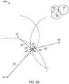
- FIG. 3Ashows a two dimensional (2D) graphical representation of a TOA target location method in a multiple receiver target location system and an example embodiment of a method for an iterative recalculating of an active RFID tag transmitter target location based on TOA measurements by the set of receivers 311 - 314 , which may be substantially similar to receivers 13 a - 1 of FIG. 5 .
- a terminology of circlesis consistent with a 2D treatment and rendering of the aforementioned method, making FIGS. 3A-3C , for example, easier to track than a three dimensional (3D) rendering.
- a set of circles 300 Arepresent the geometry of the TOA location system, relating distance and time.
- the respective radii 301 , 302 , 303 , and 304 of the set of circles 300represent subsequently determined time-of-flight (TOF) estimates for a set of receivers 311 , 312 , 313 , and 314 , corresponding to receivers 311 - 314 , from the set of receivers 311 - 314 in the receiver grid, such as the receiver grid including receivers 13 a - 1 of FIG. 5 , wherein the receivers 311 - 314 fixed physical locations are represented by crosses (+) at the circle centers for the set of circles 300 A.
- TOFtime-of-flight
- the radiuses of each circlemay be interpreted as TOAs t 1 , t 2 , t 3 , and t 4 , relative to an estimated transmission time t 0 , as measured by the receivers 311 - 314 receive clocks.
- the circles 300 Aeach represent an RFID tag transmit time estimate of the unknown true target transmit time t 0 ′.
- the TOF estimates ⁇ t 1 - ⁇ t 4which are equal to the differences between the TOAs t 1 -t 4 and the first target tag transmit time estimate t 0 , corresponding to the distances between the circle centers and the respective circles 300 A, can be readily interpreted as the radii 301 - 304 associated with the receivers 311 - 314 .
- a final location estimatemay be determined by iterative recalculation of a target location as discussed below in FIGS. 4A-4C .
- FIG. 3Bshows an example embodiment 300 B of a method for an iterative recalculating of an RFID tag transmitter target location based on TOA measurements by the set of receivers 311 - 313 in the receiver grid, in accordance with example embodiments the present invention.
- FIG. 3Bpresents an enlarged, magnified view of the previously described intersection of circles 311 - 313 ; that is, the n th location estimate X n , Y n , Z n , point 350 ′, in which circles 311 - 313 are coincident.
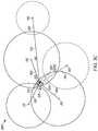
- FIG. 3Cshows an example embodiment of a method for an iterative recalculating of a 2D RFID tag transmitter target location based on TOA measurements by the set of five receivers 311 - 315 in the receiver grid, now including the fifth receiver 315 , identified as receiver 13 e .
- the collection of circles 300 Crepresent time-of-flight (TOF) estimates ⁇ t 1 - ⁇ t 4 and ⁇ t 5 for a set of receivers 311 - 315 , in the receiver grid (not shown), wherein the receivers 311 - 314 and 315 fixed physical locations are represented by crosses (+) at the circle centers for the set of circles 300 C.
- TOFtime-of-flight
- the circle radiialso each represent TOAs t 1 , t 2 , t 3 , t 4 , and t 5 relative to an RFID tag transmit time estimate, or first target time estimate t 0 , an estimate of the unknown true target transmit time t 0 ′.
- the circles 300 Cthemselves represent TOAs t 1 -t 4 and t 5 , as before, measured by the receivers 311 - 314 and 315 receiver clocks relative to an estimated target tag transmission time.
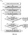
- FIG. 4Aillustrates a flow chart of a process 40 A for an iterative recalculation of a target location in a multiple receiver target location system, in accordance with embodiments of the present invention.
- the Central Processor/Hub 11may receive TOA data, such as TOA timestamps t 1 -t n received from the receivers, such as from receivers 311 - 314 , the received TOA data being measured by the respective receiver clocks.
- the circles 300 Cshown in the example embodiment given in FIG. 3C , represent the TOAs t 1 -t 5 as measured by the set of receivers 311 - 315 receiver clocks.
- a reception of a complete set of TOAs 400e.g., TOAs from receivers 311 - 315 ) at the Central Processor/Hub 11 , as designated in FIG.
- the receiver clocksmay be synchronized in frequency, but not necessarily in phase.
- a set of receiver clock synchronization offsets ⁇ nmay be applied to each of the participating receivers, for example, receivers 311 - 315 , in the RTLS TOA location estimate.
- the set of receiver clock synchronization offsets ⁇ nmay be garnered from a process involving an RX clock synchronization function for RX clocks 201 , shown in FIGS. 1-2 , and described in detail in the following sections referencing FIGS.
- a set of clock synchronization offsets ⁇ nare applied to respective TOAs at receivers 311 - 315 , for example, where each of the respective receiver clocks are offset with respect to a reference tag, as discussed in further detail in FIG. 5 .
- a current candidate combinationis generated based on the received TOA data, such as the TOA data received in block 400 .
- the current candidate combinationconsists of each receiver that provided TOA data.
- a subset of the receiversmay make up the current candidate combination in an instance in which an error is detected or the like. For example, if the difference in arrival times from any two receivers represents a distance greater than the physical distance between the same two receivers, it can be determined that one of the receivers received a substantially delayed signal.
- timestamp t jcan be discarded as being not from a direct signal.
- the RTLS target locations systemmay calculate tag locations based on the remaining received TOA data.
- the calculation of tag locationis based on a minimizing function.
- the minimizing functionis configured to calculate a location estimate (X, Y, Z) and the transmit time estimate t 0 for a candidate combination of receivers of a receiver grid of N receivers.
- the Z dimensionis assumed fixed, in some examples, for two dimensional location determinations.
- the RTLS target location systemdetermines a best solution from the one or more candidate combinations, based on results of their respective tag location calculations. This determination is based on the resulting data quality indicator, or DQI, values from each location calculation of each candidate TOA combination.
- DQIdata quality indicator
- the RTLS target location systemdetermines whether the solution identified, such as the solution determined at block 406 , satisfies a quality threshold.
- This thresholdis a configurable parameter which is used to determine the acceptability of a solution. If the DQI from the solution chosen in block 406 is below this threshold value, then that solution is taken as the overall solution, and the location computation for that tag transmission. Acceptance of the solution is indicated by block 410 .
- the RTLS target location systemdetermines whether additional candidates for removal are available (e.g., the system may require a sufficient number of receivers so as to be able generate a location estimate after one or more receivers are discarded). In some examples, the RTLS target location system may compare the number of receivers, such as the number of receivers in the current candidate combination, to a minimum receiver quantity threshold. In an example embodiment the minimum receiver quantity threshold may be a predetermined number of receivers.
- the minimum receiver quantity threshold(number of TOAs and receivers) may be four. In another example, such as a three-dimensional (3D) location estimate in a 3D RTLS system, the minimum receiver quantity threshold (number of TOAs and receivers) may be five.
- a 2D RTLS location estimatemay be determined based on three receivers and 3D RTLS location estimates may be determined based on four receivers, the additional receivers allows for an overdetermined location to be determined. The overdetermined location allows for the location estimate to be tested for agreement among the TOAs, as discussed herein.
- the minimum receiver quantity thresholdmay be a percentage of the available receivers, such as 25%, 50%, 75%, 90%, or any other percentage of available receivers. In an instance in which the minimum receiver quantity threshold is a percentage of available receivers, the percentage may be set at or above the minimum number of receivers for determining an overdetermined location.
- the methodfails indicating that a location cannot be determined for a particular iteration.
- the RTLS target location systemmay record a locate error, or “fail” at block 414 .
- further refinementmay be attempted at block 416 .
- further elimination, or pruning, of the receiver TOA datacan be performed.
- This pruningcan be performed in an exhaustive manner by forming N candidate combinations out of the set of TOAs used in the previous best solution, each with one receiver TOA missing.
- Other combinationscan be envisioned in which more than one receiver is removed to form candidate combinations.
- exhaustive pruningcan lead to the removal of legitimate, direct path TOA data in the pursuit of a lower DQI value. This simple method is unable to discriminate between TOAs from a direct or reflected path.
- some intelligencecan be applied to the pruning process by evaluating the individual contributions to the minimized function, S min , to determine the most likely receiver TOA or TOAs to have been resulting from a non-direct or reflected signal.
- S minthe minimized function
- the incremental response to this changeis a change in the four-dimensional quantity (X, Y, Z, t 0 ) for any given solution.
- a new minimization function S′may result from the perturbation.
- the change in position and time as a result of the perturbed timestampmay be the value of ⁇ right arrow over (R) ⁇ which minimizes S′.
- J⁇ S
- the receiver with correspondingly most negative value of s jis a good candidate for removal, since the TOA from that receiver would reduce S min ( ⁇ right arrow over (R) ⁇ + ⁇ right arrow over (R) ⁇ ), as shown in Equation (6), most quickly for a negative value of ⁇ t j , as would be the case if it were the result of a delayed signal.
- This methodworks well in many cases.
- a preferred methodis to determine, according to the approximation of Equation (6), what value of ⁇ t j will cause the greatest reduction in s min ( ⁇ right arrow over (r) ⁇ + ⁇ right arrow over (R) ⁇ ) for negative values, only, of ⁇ t j .
- the processreturns to block 404 with one or more candidate combinations.
- the methoditerates until a threshold is satisfied at block 408 or the method fails by way of failing to satisfy a receiver quantity threshold at block 412 .
- FIG. 4Bshows a flow chart summarizing a step-by-step process 40 B that enables an example embodiment of the method for an iterative recalculation of a target location in a multiple receiver target location system, in accordance with the present invention.
- TOAs t 1 , . . . , t nare received by the Central Processor/Hub in the multiple receiver RTLS target location system.
- a minimizing functionis applied to the measured TOAs, such as TOAs t 1 , . . . , t n .
- the TOA minimizing functionis configured to calculate a first location estimate (X 1 , Y 1 , Z 1 ) and the first target transmit time estimate t 01 for a receiver grid of n receivers.
- the minimizing functioncomprises minimizing a sum of the squares of the TOA errors s 1l , . . . , s nl . In some example embodiments, the minimizing function comprises minimizing a root-mean-square ( ⁇ right arrow over (R) ⁇ MS) of the TOA errors s 1l , . . . , s nl .
- the minimizing functioncomprising minimizing the sum of squares for example is given in Equation 13.
- ⁇ l 2S l /N l (14) Where:
- the TOA minimizing functionmay be repeated and the TOA errors s kl may be recalculated for estimated locations and transmit times proximate the first estimated locations and first estimated transmit time, until a minimum value is returned for the minimizing function value S i .
- the best first location estimate (X 1 , Y 1 , Z 1 ) and the best first target transmit time estimate t 01are determined, along with the TOA errors s k1 associated with each of the n receivers.
- the RTLS target location systemdetermines if the minimum function value S 1 or ⁇ 1 satisfies a predetermined threshold value. That is, if the first minimizing function value ⁇ 1 is less than a predetermined or programmable threshold value indicating an acceptable error value, sometimes called a DQI value, then the first minimizing function value S 1 is determined acceptable and the location estimate (X 1 , Y 1 , Z 1 ) and the target time transmit estimate t 01 are recorded. In an instance in which the threshold is satisfied, the method ends after the location estimate (X 1 , Y 1 , Z 1 ) and the target time transmit estimate t 01 are recorded as is shown in block 426 .
- the RTLS target location systemdetermines whether a minimum number of receivers are available for a location determination (e.g., the system as a sufficient number of receivers so as to be able generate a location estimate or overdetermined location estimate). In some examples, the RTLS target location system may compare the number of receivers to a minimum threshold. In some examples, such as a two-dimensional (2D) position estimate in a 2D RTLS system, the minimum threshold (number of TOAs and receivers) may be four. In another example, such as a three-dimensional (3D) position estimate in a 3D RTLS system, the minimum threshold (number of TOAs and receivers) may be 5.
- 2Dtwo-dimensional
- 3Dthree-dimensional
- the methodfails indicating that a location cannot be determined.
- the RTLS target location systemmay record a locate error, or “fail”.
- the RTLS target systemremoves a receiver with the largest TOA error value as determined in equation 12, e.g. the receiver which would have the largest effect on S 1 if removed to correct the error (late TOA).
- the RTLS target location systemmay remove a receiver from the set of n receivers, wherein the receiver that is removed is associated with the maximum TOA error s kl from the set of n TOA errors s 1l , . . . , s nl , as given in Equation 15.
- s kl > ⁇ 1 ⁇ square root over ( ⁇ s kl 2 /N l ) ⁇⁇ l (15)
- THENDiscard the k th receiver.
- ⁇ 1may be a fixed scalar multiplier; alternatively, ⁇ 1 may change dynamically.
- FIG. 4Cshows a flow chart summarizing a step-by-step process 40 C that enables an example embodiment of the method for an iterative recalculation of a target location in a multiple receiver target location system, in accordance with the present invention.
- the step-by-step process 40 Crepresents an iterative recalculation of a target location for an RTLS target location system.
- TOAs t 1 , . . . , t 5are received by the Central Processor/Hub in the multiple receiver RTLS target location system.
- the RTLS target location systemmay calculate a minimizing function value S k using a TOA minimizing function, such as the TOA minimizing function described above with respect to FIG. 4B .
- the RTLS target locations systemmay test the minimizing function value error, S k calculated by the TOA minimizing function at step 436 , against all previously calculated error values.
- the minimizing function value erroris S k the smallest error when compared to other error calculations
- the receiver combination and the minimum function value error S kis recorded in step 440 .
- the RTLS target location systemmay determine if all m combinations of receivers has been selected and calculated, e.g. if a receiver combination threshold has been satisfied.
- a receiver combination thresholde.g. if a receiver combination threshold has been satisfied.
- the process 40 Cis completed at step 444 with the position estimate being selected based on the combination of receivers, k* that had the smallest error calculation as determined in block 438 .
- a new combination of n or fewer TOAs from the associated original receiver setis selected in a (n,K) th permutation.
- the RTLS target location systemmay remove and replace receivers TOAs iteratively until each of the m receiver combinations has been calculated. The process may continue at step 436 .
- an advantage of process 40 B in FIG. 4Bis minimal processing time and processing power requirements. Additionally, 40 B is more likely to discriminate late arrival TOAs. In other examples, an advantage of process 40 C in FIG. 4C is a more complete analysis of possible TOA combinations, resulting in, predictably, a better, more accurate RTLS location estimate. (X k *, Y k *, Z k *).
- the independent variables estimated for the first minimizing functionare the first location estimate (X 1 , Y 1 , Z 1 ) and the first target transmit time estimate t 01 .
- the first location estimateis represented by the coordinates (X 1 , Y 1 , Z 1 ), and combined with the first target transmit time t 01 , provides for three independent variables.
- a collection of three TOA constraints from the three receivers 13 a - ccritically determines the dependent TOA errors s 1 , . . . , s 3 . That is, represented graphically, the three circles 311 - 313 from the set of circles 300 intersect at a point, whereby the circles 311 - 313 represent the first target location estimate, as previously noted, the radii 301 - 303 represent the TOFs ⁇ t 1 - ⁇ t 3 , and the resulting TOA errors s 1 , . . . , s 3 are each zero.
- a collection of three TOA constraints from the three receivers 13 a - ccritically determines the dependent TOA errors s 1 , . . . , s 3 .
- the three circles 311 - 313 from the set of circles 300intersect at a point, whereby the circles 311 - 313 represent the first target location estimate, as previously noted, the radii 301 - 303 represent the TOFs ⁇ t 1 - ⁇ t 3 , and the resulting TOA errors s 1 , . . . , s 3 are each zero.
- FIG. 3Bgraphically represents an example step in the iteration of the minimizing function, given in equations 12-14, wherein the independent variables (X, Y, Z) and t 0 are converging such that the first minimizing function value S is approaching zero; that is, that each of the TOA errors s 1 , . . . , s 3 are simultaneously converging to zero, as discussed in the previous section.
- the three TOA errorsare equal to each other, and the final location estimate (X, Y, Z), the point 350 ′, it follows, has already converged.
- FIG. 3Bgraphically represents a critically-determined 2D RTLS location system.
- FIG. 3Aprovides for four TOAs t 1 -t 4 from four receivers 311 - 314 , and as such FIG. 3A graphically represents an over-determined 2D RTLS location system.
- each location estimate (X, Y, Z) and associated first target transmit time estimate t 0 from each combination of three receivers from the set of four receivers 311 - 314is equally valid.
- TOA errorthere must be at least five TOAs t 1 -t 5 generated from five receivers 311 - 315 for the 2D RTLS location system.
- the first minimizing functionmay now produce a first location estimate (X 1 , Y 1 , Z 1 ) 350 ′′, in accordance with Equations 12-14.
- Implementation of a method for comparing TOA errors s 1 , . . . , s 5 , given in Equation 115,may determine that the TOA error s 5 is significantly larger than the TOA errors s 1 , . . . , s 4 , that TOA t 5 associated with the receiver 315 ( 13 e ) is an outlier, and should be discarded.
- Equations 12-15provide form identical functions as the first iteration, searching the space-time regime now for a second location estimate X 2 , Y 2 , Z 2 and a second target transmit time t 2 to find the second minimizing function value ⁇ T 2 for minimizing the second minimizing function in Equations 12-14.
- the second location estimate (X 2 , Y 2 , Z 2 )is made by minimizing a second minimizing function value S 2 from a second minimizing function, wherein the second minimizing function comprises a set of distance or timing errors, TOA errors s 1 , . . . , s 4 between TOF estimates ⁇ t 1 - ⁇ t 4 and the distance from the circle centers to the second location estimate (X 2 , Y 2 , Z 2 ).
- the second minimizing functioncomprises minimizing a sum of the squares of the TOA errors s 1 , . . . , s 4 . In some embodiments, the second minimizing function comprises minimizing an RMS of the TOA errors s 1 , . . . , s 4 .
- the second minimizing functioncomprising minimizing the sum of squares and the second minimizing function comprising minimizing the RMS map directly onto Equations 12-14, respectively, presented previously for FIG. 3A .
- the present inventionaddresses the TOA measurement errors in the set of receivers 311 - 315 in the receiver grid, shown in FIG. 3C , and presents a method for iteratively recalculating the second minimizing function to significantly improve the second location estimate (X 2 , Y 2 , Z 2 ) over and above the first location estimate (X 1 , Y 1 , Z 1 ) discarding TOA errors that are outliers.
- the method for comparing the TOA errors, s 1 , . . . , s 4 following completion of the second minimizing functionmaps directly onto the method for comparing the TOA errors s 1 , . . . , s 4 , given in Equation 15, presented previously in conjunction with the first minimizing function and FIG. 3A .
- the method for iteratively recalculating the second minimizing functionallows for a second scalar multiplier ⁇ 2 to be introduced into the second minimizing function.
- ⁇ 2may be a fixed scalar multiplier.
- ⁇ 2may change dynamically.
- ⁇ 2may be a fixed scalar multiplier, but have a different value from ⁇ 1 .
- the iterative recalculating of (X l , Y l , Z l ) and t 0lmay continue for a prescribed number of iterations. In some embodiments, the iterative recalculating of (X l , Y l , Z l ) and t 0l may continue until such point that no further TOA errors s kl , and no additional associated receivers, such as the receiver 315 ( 13 e ) in the example from FIG. 3C , are discarded, in accordance with the l th minimizing function.
- the second location estimate (X 2 , Y 2 , Z 2 )may provide for a smaller value for the second minimizing function value ⁇ 2 for the second minimizing function; that is, ⁇ 2 ⁇ 1 .
- the smaller second minimizing function value ⁇ 2 for the second minimizing functionmay represent an improvement in the accuracy of the second location estimate (X 2 , Y 2 , Z 2 ) over the first location estimate (X 0 , Y 0 , Z 0 ).
- the potential improvement in accuracy represented by the second location estimate (X 2 , Y 2 , Z 2 )may be a direct effect of the absence of the TOA error t 5 , the absence of the receiver 315 ( 13 e ) from FIG. 3C , from the second minimization function. If so, it may be that erratic effects associated with target location in the TOA target location system may be attributed to the receiver 315 from FIG. 3C , and further may be a direct result of a multipath channel associated with the receiver 315 or a random noise received at the receiver 315 .
- FIG. 5illustrates an exemplary locating system 500 useful for calculating a location by an accumulation of location data or time of arrivals (TOAs) at a central processor/hub 11 , whereby the TOAs represent a relative time of flight (TOF) from RTLS tags 12 a - f as recorded at each receiver 13 a - 1 (e.g., UWB reader, etc.).
- TOFtime of flight
- a timing reference clockis used, in some examples, such that at least a subset of the receivers 13 a - 1 may be synchronized in frequency, whereby the relative TOA data associated with each of the RTLS tags 12 a - f may be registered by a counter associated with at least a subset of the receivers 13 a - 1 .
- a reference tag 14 a - bpreferably a UWB transmitter, positioned at known coordinates, is used to determine a phase offset between the counters associated with at least a subset of the of the receivers 13 a - 1 .
- the RTLS tags 12 a - f and the reference tags 14 a - breside in an active RTLS field 18 .
- the systems described hereinmay be referred to as either “multilateration” or “geolocation” systems, terms that refer to the process of locating a signal source by solving an error minimization function of a location estimate determined by the difference in time of arrival (DTOA) between TOA signals received at multiple receivers 13 a - 1 .
- DTOAdifference in time of arrival
- the systemcomprising at least the tags 12 a - f and the receivers 13 a - 1 is configured to provide two dimensional and/or three dimensional precision localization (e.g., subfoot resolutions), even in the presence of multipath interference, due in part to the use of short nanosecond duration pulses whose TOF can be accurately determined using detection circuitry, such as in the receivers 13 a - 1 , which can trigger on the leading edge of a received waveform.
- this short pulse characteristicallows necessary data to be conveyed by the system at a higher peak power, but lower average power levels, than a wireless system configured for high data rate communications, yet still operate within local regulatory requirements.
- the tags 12 a - fmay operate with an instantaneous ⁇ 3 dB bandwidth of approximately 400 MHz and an average transmission below 187 pulses in a 1 msec interval, provided that the packet rate is sufficiently low.
- the predicted maximum range of the systemoperating with a center frequency of 6.55 GHz, is roughly 200 meters in instances in which a 12 dbi directional antenna is used at the receiver, but the projected range will depend, in other examples, upon receiver antenna gain.
- the range of the systemallows for one or more tags 12 a - f to be detected with one or more receivers positioned throughout a football stadium used in a professional football context.
- Such a configurationadvantageously satisfies constraints applied by regulatory bodies related to peak and average power densities (e.g., effective isotropic radiated power density (“EIRP”)), while still optimizing system performance related to range and interference.
- EIRPeffective isotropic radiated power density
- tag transmissions with a ⁇ 3 dB bandwidth of approximately 400 MHzyields, in some examples, an instantaneous pulse width of roughly 2 nanoseconds that enables a location resolution to better than 30 centimeters.
- the object to be locatedhas an attached tag 12 a - f , preferably a tag having a UWB transmitter, that transmits a burst (e.g., multiple pulses at a 1 Mb/s burst rate, such as 112 bits of On-Off keying (OOK) at a rate of 1 Mb/s), and optionally, a burst comprising an information packet utilizing OOK that may include, but is not limited to, ID information, a sequential burst count or other desired information for object or personnel identification, inventory control, etc.
- a burste.g., multiple pulses at a 1 Mb/s burst rate, such as 112 bits of On-Off keying (OOK) at a rate of 1 Mb/s
- OOKOn-Off keying
- the sequential burst count(e.g., a packet sequence number) from each tag 12 a - f may be advantageously provided in order to permit, at a Central Processor/Hub 11 , correlation of TOA measurement data from various receivers 13 a - 1 .
- the tag 12 a - fmay employ UWB waveforms (e.g., low data rate waveforms) to achieve extremely fine resolution because of their extremely short pulse (i.e., sub-nanosecond to nanosecond, such as a 2 nsec (1 nsec up and 1 nsec down)) durations.
- the information packetmay be of a short length (e.g. 112 bits of OOK at a rate of 1 Mb/sec, in some example embodiments), that advantageously enables a higher packet rate. If each information packet is unique, a higher packet rate results in a higher data rate; if each information packet is transmitted repeatedly, the higher packet rate results in a higher packet repetition rate.
- higher packet repetition ratee.g., 12 Hz
- higher data ratese.g., 1 Mb/sec, 2 Mb/sec or the like
- the shorter length of the information packetsin conjunction with other packet rate, data rates and other system requirements, may also result in a longer battery life (e.g., 7 years battery life at a transmission rate of 1 Hz with a 300 mAh cell, in some present embodiments).
- Tag signalsmay be received at a receiver directly from RTLS tags, or may be received after being reflected en route. Reflected signals travel a longer path from the RTLS tag to the receiver than would a direct signal, and are thus received later than the corresponding direct signal. This delay is known as an echo delay or multipath delay. If reflected signals are sufficiently strong enough to be detected by the receiver, they can corrupt a data transmission through inter-symbol interference.
- the tag 12 a - fmay employ UWB waveforms to achieve extremely fine resolution because of their extremely short pulse (e.g., 2 nsec) durations.
- signalsmay comprise short information packets (e.g., 112 bits of OOK) at a somewhat high burst data rate (1 Mb/sec, in some example embodiments), that advantageously enable packet durations to be brief (e.g., 112 usec) while allowing inter-pulse times (e.g., 998 nsec) sufficiently longer than expected echo delays, avoiding data corruption
- Reflected signalscan be expected to become weaker as delay increases due more reflections and to the longer distances traveled.
- inter-pulse timee.g. 998 nsec
- path length differencee.g. 299.4 m.
- minimization of packet durationallows the battery life of a tag to be maximized, since its digital circuitry need only be active for a brief time. It will be understood that different environments can have different expected echo delays, so that different burst data rates and, hence, packet durations, may be appropriate in different situations depending on the environment.
- Minimization of the packet durationalso allows a tag to transmit more packets in a given time period, although in practice, regulatory average EIRP limits may often provide an overriding constraint.
- brief packet durationalso reduces the likelihood of packets from multiple tags overlapping in time, causing a data collision.
- minimal packet durationallows multiple tags to transmit a higher aggregate number of packets per second, allowing for the largest number of tags to be tracked, or a given number of tags to be tracked at the highest rate.
- a data packet length of 112 bits(e.g., OOK encoded), transmitted at a data rate of 1 Mb/sec (1 MHz), may be implemented with a transmit tag repetition rate of 1 transmission per second (1 TX/sec).
- Such an implementationmay accommodate a battery life of up to seven years, wherein the battery itself may be, for example, a compact, 3-volt coin cell of the series no. BR2335 (Rayovac), with a battery charge rating of 300 mAhr.
- An alternate implementationmay be a generic compact, 3-volt coin cell, series no. CR2032, with a battery charge rating of 220 mAhr, whereby the latter generic coin cell, as can be appreciated, may provide for a shorter battery life.
- some applicationsmay require higher transmit tag repetition rates to track a dynamic environment.
- the transmit tag repetition ratemay be 12 transmissions per second (12 TX/sec). In such applications, it can be further appreciated that the battery life may be shorter.
- the high burst data transmission rate(e.g., 1 MHz), coupled with the short data packet length (e.g., 112 bits) and the relatively low repetition rates (e.g., 1 TX/sec), provide for two distinct advantages in some examples: (1) a greater number of tags may transmit independently from the field of tags with a lower collision probability, and/or (2) each independent tag transmit power may be increased, with proper consideration given to a battery life constraint, such that a total energy for a single data packet is less that an regulated average power for a given time interval (e.g., a 1 msec time interval for an FCC regulated transmission).
- an regulated average power for a given time intervale.g., a 1 msec time interval for an FCC regulated transmission.
- additional sensor or telemetry datamay be transmitted from the tag 12 a - f to provide the receivers 13 a - 1 with information about the environment and/or operating conditions of the tag.
- the tagmay transmit a temperature to the receivers 13 a - 1 .
- Such informationmay be valuable, for example, in a system involving perishable goods or other refrigerant requirements.
- the temperaturemay be transmitted by the tag at a lower repetition rate than that of the rest of the data packet.
- the temperaturemay be transmitted from the tag to the receivers at a rate of one time per minute (e.g., 1 TX/min.), or in some examples, once every 720 times the data packet is transmitted, whereby the data packet in this example is transmitted at an example rate of 12 TX/sec.
- a rate of one time per minutee.g., 1 TX/min.
- the data packet in this exampleis transmitted at an example rate of 12 TX/sec.
- the tag 12 a - fmay be programmed to intermittently transmit data to the receivers 13 a - 1 in response to a signal from a magnetic command transmitter (not shown).
- the magnetic command transmittermay be a portable device, functioning to transmit a 125 kHz signal, in some example embodiments, with a range of approximately 15 feet or less, to one or more of the tags 12 a - f .
- the tags 12 a - fmay be equipped with at least a receiver tuned to the magnetic command transmitter transmit frequency (e.g., 125 kHz) and functional antenna to facilitate reception and decoding of the signal transmitted by the magnetic command transmitter.
- one or more other tagsmay be positioned within and/or about a monitored region.
- the reference tag 14 a - bmay be configured to transmit a signal that is used to measure the relative phase (e.g., the count of free-running counters) of non-resettable counters within the receivers 13 a - 1 .
- One or more (e.g., preferably four or more) receivers 13 a - 1are also positioned at predetermined coordinates within and/or around the monitored region.
- the receivers 13 a - 1may be connected in a “daisy chain” 19 fashion to advantageously allow for a large number of receivers 13 a - 1 to be interconnected over a significant monitored region in order to reduce and simplify cabling, provide power, and/or the like.
- Each of the receivers 13 a - 1includes a receiver for receiving transmissions, such as UWB transmissions, and preferably, a packet decoding circuit that extracts a time of arrival (TOA) timing pulse train, transmitter ID, packet number, and/or other information that may have been encoded in the tag transmission signal (e.g., material description, personnel information, etc.) and is configured to sense signals transmitted by the tags 12 a - f and one or more reference tags 14 a - b.
- TOAtime of arrival
- Each receiver 13 a - 1includes a time measuring circuit that measures times of arrival (TOA) of tag bursts, with respect to its internal counter.
- the time measuring circuitis phase-locked (e.g., phase differences do not change and therefore respective frequencies are identical) with a common digital reference clock signal distributed via cable connection from a Central Processor/Hub 11 having a central timing reference clock generator.
- the reference clock signalestablishes a common timing reference for the receivers 13 a - 1 .
- multiple time measuring circuits of the respective receivers 13 a - 1are synchronized in frequency, but not necessarily in phase.
- each receivermay be synchronized wirelessly via virtual synchronization without a dedicated physical timing channel.
- the receivers 13 a - 1are configured to determine various attributes of the received signal. Since measurements are determined at each receiver 13 a - 1 , in a digital format, rather than analog in some examples, signals are transmittable to the Central Processor/Hub 11 .
- the receivers 13 a - 1can receive and process tag (and corresponding object) locating signals on a nearly continuous basis.
- the receiver memoryallows for a high burst rate of tag events (i.e., information packets) to be captured.
- Data cables or wireless transmissionsmay convey measurement data from the receivers 13 a - 1 to the Central Processor/Hub 11 (e.g., the data cables may enable a transfer speed of 2 Mbps). In some examples, measurement data is transferred to the Central Processor/Hub at regular polling intervals.
- the Central Processor/Hub 11determines or otherwise computes tag location (i.e., object location) by processing TOA measurements relative to multiple data packets detected by the receivers 13 a - 1 .
- the Central Processor/Hub 11may be configured to resolve the coordinates of a tag using nonlinear optimization techniques.
- TOA measurements from multiple receivers 13 a - 1are processed by the Central Processor/Hub 11 to determine a location of the transmit tag 12 a - f by a differential time-of-arrival (DTOA) analysis of the multiple TOAs.
- the DTOA analysisincludes a determination of tag transmit time t 0 , whereby a time-of-flight (TOF), measured as the time elapsed from the estimated tag transmit time t 0 to the respective TOA, represents graphically the radii of spheres centered at respective receivers 13 a - 1 .
- TOFtime-of-flight
- the distance between the surfaces of the respective spheres to the estimated location coordinates (X 0 , Y 0 , Z 0 ) of the transmit tag 12 a - frepresents the measurement error for each respective TOA, and the minimization of the sum of the squares of the TOA measurement errors from each receiver participating in the DTOA location estimate provides for both the location coordinates (X 0 , Y 0 , Z 0 ) of the transmit tag and of that tag's transmit time t 0 .
- the system described hereinmay be referred to as an “over-specified” or “over-determined” system.
- the Central Processor/Hub 11may calculate one or more valid (i.e., most correct) locations based on a set of measurements and/or one or more incorrect (i.e., less correct) locations. For example, a location may be calculated that is impossible due the laws of physics or may be an outlier when compared to other calculated locations. As such one or more algorithms or heuristics may be applied to minimize such error.
- the starting point for the minimizationmay be obtained by first doing an area search on a coarse grid of x, y and z over an area defined by the user and followed by a localized steepest descent search.
- the starting position for this algorithmis fixed, in some examples, at the mean position of all active receivers. No initial area search is needed, and optimization proceeds through the use of a Davidon-Fletcher-Powell (DFP) quasi-Newton algorithm in some examples. In other examples, a steepest descent algorithm may be used.
- DFPDavidon-Fletcher-Powell
- a steepest descent algorithmmay be used.
- Nis the number of receivers
- cis the speed of light
- X j , Y j , Z jare the coordinates of the j th receiver
- t jis the arrival time at the jth receiver
- t 0is the tag transmit time.
- the variable t 0represents the time of transmission. Since t 0 is not initially known, the arrival times, t j , as well as t 0 , are related to a common time base, which in some examples, is derived from the arrival times. As a result, differences between the various arrival times have significance for determining location as well as t 0 .
- the optimization algorithm to minimize the error S in Equation 16may be the Davidon-Fletcher-Powell (DFP) quasi-Newton algorithm, for example.
- the optimization algorithm to minimize the error S in Equation 13may be a steepest descent algorithm.
- the algorithmsmay be seeded with an initial location estimate (X, Y, Z) that represents the two-dimensional (2D) or three-dimensional (3D) mean of the positions of the receivers 13 a - 1 that participate in the RTLS location determination.
- the RTLS systemcomprises a receiver grid, whereby each of the receivers 13 a - 1 in the receiver grid keeps a receiver clock that is synchronized, with an initially unknown phase offset, to the other receiver clocks.
- the phase offset between any receiversmay be determined by use of a reference tag that is positioned at a known coordinate position (X T , Y T , Z T ).
- the phase offsetserves to resolve the constant offset between counters within the various receivers 13 a - 1 , as described below.
- Each receiver Rjutilizes, for example, a synchronous clock signal derived from a common frequency time base, such as a clock generator. Because the receivers are not synchronously reset, an unknown, but constant offset Oj exists for each receiver's internal free running counter. The value of the constant offset Oj is measured in terms of the number of fine resolution count increments (e.g., a number of nanoseconds for a one nanosecond resolution system).
- the reference tagis used, in some examples, to calibrate the radio frequency locating system as follows:
- the reference tagemits a signal burst at an unknown time ⁇ R.
- phase offsets expressed as differential count valuesare determined as given in Equations 20 and 21:
- Each arrival time, t jcan be referenced to a particular receiver (receiver “1”) as given in Equation 24:
- Equation 13The minimization, described in Equation 13, may then be performed over variables (X, Y, Z, t 0 ) to reach a solution (X′, Y′, Z′, t 0 ′).
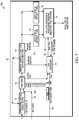
- FIG. 6illustrates an exemplary receiver 13 a - 1 in a UWB receiver system 600 comprising a UWB receiver that may be configured in accordance with some embodiments of the present invention.
- data packetsare transmitted to the receivers 13 a - 1 and intercepted by UWB antenna 21 .
- a UWB receiver 22is provided at each receiver 13 a - 1 .
- the UWB receivercan, for example, be designed in accordance with the system described in commonly-owned U.S. Pat. No. 5,901,172, which is incorporated by reference herein in its entirety.
- UWB receiver 22provided for at receivers 13 a - 1 , allows for an analog signal stream that is digitized, then processed by a UWB TOA and data recovery circuits 24 .
- the analog streamis digitized by up to three or more parallel, concurrent, independent analog-to-digital convertors (ADCs) functioning with three distinct threshold levels, resulting in up to three or more digital data streams 23 A-C that are sent to the UWB TOA and data recovery circuits 24 .
- the threshold levels applied to the analog signal stream in the UWB receiver 22are a function of a signal-to-noise ratio (SNR) present in the communication channel.
- the threshold levelsare set dynamically as a function of one or more of an antenna preamp gain and an estimated RTLS tag range.
- the UWB TOA and data recovery circuits 24perform as many as three or more parallel, concurrent, identical signal processing functions on the three or more digital data streams 23 A-C.
- the three or more UWB TOA and data recovery circuits 24may be configured to receive data packets that correspond to RTLS tags 12 a - f .
- the UWB TOA and data recovery circuits 24may provide for a packet framing and extraction function as part of the data recovery circuit, whereby an RTLS tag 12 a - f identification may be extracted.
- the RTLS identificationmay be extracted by the TX identification field 120 B of the data packet, as described previously.
- the UWB TOA and data recovery circuits 24are implemented by field programmable gate arrays (FPGAs).
- the TOA and extracted data packetis sent by TOA line 25 to an arbitrate/buffer function 26 .
- the arbitrate/buffer function 26effectively selects the TOA line 25 data provided by the UWB TOA and data recovery circuits 24 .
- the arbitrate/buffer function 26selects the TOA line 25 that converges to the earliest TOA from the up to three or more TOA and data recovery circuits 24 driven by the digital data stream 23 A-C.
- the arbitrate/buffer function 26provides for a series of serial messages, or tag message 27 , to send to a tag queue function 28 , whereby each of the tag messages 27 is identified by an RTLS tag 12 a - f and an associated TOA.
- the tag queue function 28provides for a formatting and ordering of the collection of RTLS tag identifiers and TOAs, effectively a first-in first-out (FIFO) memory buffer awaiting a transmission to the central processor/hub 11 .
- a tag data packet 29is sent to a formatting and data coding/decoding function 30 that, in turn, repackages the tag data packet 29 and transmits a synchronous tag data packet 30 B to the central processor/hub 11 .
- the synchronous tag data packet 30 B transmitted by the formatting and data coding/decoding function 30 to the central processor/hub 11is synchronized by a 10 MHz receiver clock 40 , received from the previous receiver clock in the “daisy chain” 19 , and transmitted to the next receiver clock in the “daisy chain” 19 following a synchronous frequency up/down convert.
- the receiver clock 40drives a phase-locked loop (PLL) 41 , whereby a frequency divider in a feedback loop in conjunction with a voltage-controlled oscillator (VCO) provides for a 100 MHz receiver clock 42 - 43 that is synchronized in phase to the 10 MHz receiver clock 40 .
- PLLphase-locked loop
- VCOvoltage-controlled oscillator
- the 100 MHz receiver clock 42is provided to synchronize all logic blocks in the UWB receiver 13 a - 1 and to provide for a TOA coarse time 45 , sent by line 46 to the TOA and data recovery circuits 24 to be used in the TOA determination.
- the 100 MHz receiver clock 43provides for the parallel set of fine detector windows 340 , a basis of a set of receiver timing windows used to capture and register pulses transmitted by RTLS tags 12 a - f in the TOA determination, as described previously with respect to FIG. 3 .
- a second function of the formatting and data coding/decoding function 30is a buffering, reformatting, and repeating of a central processor data 30 A-B received and transmitted between the receiver 13 a - 1 and the central processor/hub 11 via the “daisy chain” 19 receiver network.
- the central processor data 30 A-B received and transmitted from and to the formatting and data coding/decoding function 30may provide for a series of commands that are decoded at a command decoder 44 to trigger receiver functions.
- a non-exhaustive list of such functionsmay include the following: an auto/manual control function 20 , a series of telemetry functions 60 , and the arbitrate/buffer function 26 to prune a data queue and to manage, delete, and reorder the data queue.
- the auto/manual control function 20may be commanded—from manual mode—to report sensor information such as temperature and other telemetry data recorded in the telemetry function 60 , and may be commanded to manually adjust one or more of an antenna preamp gain and the previously described threshold levels at the UWB receiver 22 .
- a power supply 50may be configured to power the receiver 13 a - 1 by way of an AC-DC convertor, whereby the AC power may be provided as an input from the central processor/hub 11 , shown in FIG. 5 .
- the power supply 50may be accompanied, in some embodiments, by a power delay circuit 51 to allow for an orderly ‘power up’ of sequential receivers 13 a - 1 , thus avoiding a power surge and over-current event in the central processor data 30 A-B transmission lines.
- An advantage, in some examples, to the present embodiment of the UWB receiver system 600is that packet data and measurement results can be transferred at high speeds to TOA measurement buffers, the arbitrate/buffer function 26 , such that the receivers 13 a - 1 can receive and process tag 12 a - f (and corresponding object) locating signals on a nearly continuous basis. That is, multiple UWB data packets can be processed in close succession, thereby allowing the use of hundreds to thousands of tag transmitters.
- data stored in TOA measurement buffers, the arbitrate/buffer function 26is sent to a central processor/hub 11 , shown in FIG. 5 , over the central processor data transmission lines 30 A-B in response to a specific request from the central processor/hub 11 .
- the collection of the central processor data 30 A-B transmission lines, connecting a “daisy chain” 19 network of receiversis comprised of two bi-directional data links.
- these data linksmay be RS422 differential serial links.
- a network interfacemay receive command signals from a central processor/hub 11 on one link, for example, to instruct a transfer of the TOA measurement buffer, the arbitrate/buffer function 26 , to the central processor/hub 11 . Additional commands may include those to adjust UWB receiver 22 operating characteristics such as gain and detection thresholds.
- the bi-directional data linksmay also provide for a buffer for data signals linked between “daisy chain” 19 receivers, buffering sequential transmissions between the present and next receiver 13 a - 1 in a communications chain.
- the synchronous frequency up/down convert performed on the 10 MHz receiver clock 40provides for a driver for the receiver clock 40 transmitted to the next receiver in the “daisy chain” 19 .
- An advantage of this approachis that the 10 MHz receiver clock 40 transmitted to the next receiver—as with the original 10 MHz receiver clock 40 —may be made low enough in frequency so that it can be transmitted over low-cost cables (e.g., twisted pair wires). Since timing jitter of the local timing reference signal degrades as the PLL multiplier coefficient is increased, there is a necessary trade-off between frequency and jitter of the local timing reference signal and the frequency of the timing reference clock.
- a plurality of local timing reference signals(one in each receiver) can be precisely matched in frequency.
- additional receiverscan be connected without concern for clock loading. Buffer delay is also not an issue since the timing reference clock is used for frequency only, and not phase reference.
- the 10 MHz receiver clock 40may comprise differential signals.
- the use of differential clock signalsis advantageous since they avoid clock duty cycle distortion which can occur with the transmission of relatively high-speed clocks (e.g., >10 MHz) on long cables (e.g., >100 feet).
- FIG. 7illustrates an exemplary embodiment of the UWB TOA and data recovery circuits 700 , presented in the UWB receiver system 600 as TOA and data recovery circuits 24 , shown in FIG. 6 , in accordance with some embodiments of the present invention.
- the UWB TOA data and recovery circuits 700comprise a windowing/gating function 71 , a TOA function 72 , a window control clock and data recovery (PLL) function 73 , a TOA averaging function 74 , a data sync and extract function (1 MHz-2 MHz) 75 - 76 , and a tag data recovery and processing function 77 .
- the UWB TOA and data recovery circuits 700process the digital data stream 23 , shown in FIG. 6 , to provide an unpacked data packet and the TOA associated with the RTLS tag to the arbitrate/buffer function 26 .
- the windowing/gating function 71 and the window control clock and data recovery (PLL) function 73work as a feedback loop to recover the TX clock 101 and provide for the adjustable timing window functions 100 and 200 , as presented in FIGS. 1-2 , by tracking the RX pulses 111 R′ that comprise the RX pulse train 211 R corresponding to the TX pulses 111 T′ in the series of TX pulses 111 in the preamble 110 .
- the TOA function 72works in conjunction with the 100 MHz receiver clocks 42 - 43 .
- the RX clock 42 ( 201 )provides for the TOA coarse time 46 .
- the parallel set of fine detector windows 43provides for a TOA fine time associated with an RX fine timing window function, recording detections by a registration code for the RX pulses 111 R′ that correspond to a sync code of TX pulses 111 T′.
- the description for the adjustable timing window functions 100 and 200are given with the presentation of FIGS. 1-2 .
- the TOA fine time, the disjoint timing windows 233 A-C, as determined by the adjustable timing window functions 100 and 200 , and the coarse time 46are sent to the TOA averaging function 74 , along with a latch TOA control signal indicating the end of a TOA determination.
- the TOA averaging function 74is activated by a calculate TOA trigger 78 , whereby a sub-window resolution function is initiated to determine the TOA with sub-window accuracy; that is, with resolution less than 1 nsec.
- the averaged TOA 80is then sent to the tag data recovery and processing function 77 .
- the data sync and extract functions (1 MHz-2 MHz) 75 - 76are triggered upon phase lock of the PLL associated with the window control clock and data recovery (PLL) function 73 .
- Phase lock of the PLLis determined by the previously described feedback loop comprising the windowing/gating function 71 and the window control clock and data recovery (PLL) function 73 , whereby the feedback loop effectively recovers the TX clock 101 by tracking the RX pulses 111 R′ corresponding to the preamble 110 .
- the data packetUpon phase lock, whereby the preamble 110 is synchronized to a recovered TX clock, the data packet, beginning with the remainder of the preamble 110 , is extracted and unpacked by the data sync and extract function 75 ( 76 ) at a sampling rate of 1 Mhz (2 MHz), and sent to the tag data recovery and processing function 77 .
- the data sync and extract functions 75 - 76are both set to sample the data packet with a sampling rate of 2 MHz, but the two functions may differ by a data format.
- the data extracted by function 75may follow a non-IOS format, where the data extracted by function 76 may follow an IOS format.
- the tag data recovery and processing function 77serves as a data processor for the data extracted by the data sync and extract functions 75 - 76 and as a communications control function, and also provides for data exchange associated with the arbitrate/buffer function 26 , shown in FIG. 6 .
- the data tag recovery and processing function 77sends the TOA and data packet information from the TOA averaging function 74 and the data sync and extract functions 75 , 76 , respectively, on TOA line 25 to the arbitrate/buffer function 26 , which reformats and repacks selects the earliest TOA from the three TOA functions running concurrently in the UWB TOA and data recovery circuits 700 , and combines the TOA with the data packet data into a tag message 27 to send to the tag data queue 28 .
- the tag message 27comprises at least the average TOA 80 and a TX ID extracted from the data packet associated with the given tag transmission.
- the tag data queue 28as described previously with respect to FIG. 6 , effectively functions as a FIFO buffer for data transmission to the central processor/hub 11 .
- the tag data recovery and processing function 77also serves as a controller for the timing of a triggering of the TOA averaging function 74 and a locking/unlocking 79 of the PLL in the window control clock and data recovery (PLL) function 73 .
- the TOA averaging function 74is initiated by the calculate TOA trigger 78 set by the tag data memory and processing controller 77 , whereby the TOA trigger 78 is a function of a sync code 112 detection and a waiting interval associated with the data sync and extract function 75 - 76 .
- the locking/unlocking 79 of the PLLis a function of a PLL lock indication initiated at the window control clock and data recovery (PLL) function 73 , as described previously. And the locking/unlocking 79 of the PLL is reset to unlock the PLL upon detection in the sync and data extract functions 75 - 76 that the end of the data packet has been reached, that the sampling of the data packet for the given tag transmission is complete.
- the TOA averaging function 74is initiated by the calculate TOA trigger 78 .
- the TOA averaging function 74may, in some examples, register a transition as successive RX pulses 111 R′ exhibit a change in a detection registration.
- a TOA numerical averagemay be constructed to assign a TOA with sub-window resolution.
- a TOA numerical averagemay be constructed, whereby RX pulses 111 R′ 1 - 5 , for example, are assigned a weight equal to a 4 nsec time difference referenced to the leading edge of the final center disjoint timing window 233 B, and whereby RX pulses 111 R′ 6 - 8 are assigned a weight equal to a 3 nsec time difference referenced to the leading edge of the final center disjoint timing window 233 B.
Landscapes
- Physics & Mathematics (AREA)
- Engineering & Computer Science (AREA)
- General Physics & Mathematics (AREA)
- Radar, Positioning & Navigation (AREA)
- Remote Sensing (AREA)
- Position Fixing By Use Of Radio Waves (AREA)
Abstract
Description
c(tj−ti)>dij=√{square root over ((xi−xj)2+(yi−yj)2+(zi−zj)2)} (1)
then timestamp tjcan be discarded as being not from a direct signal.
sj=dj−C(tj−t0) (2)
where sj represents the TOA error for the jth receiver, and dj=√{square root over ((X−xj)2+(Y−yj)2+(Z−zj)2)} is the distance from computed location (X, Y, Z) to receiver j, and t0is the computed transmission time. The computed location and transmission time, (X, Y, Z, t0), are determined by minimizing the sum of squares of the TOA errors:
minX,Y,Z,t
where the summation is taken over TOA data from all receivers in the candidate combination.
S′({right arrow over (R)}′)=S|{right arrow over (R)}+Δ{right arrow over (R)}·∇S|{right arrow over (R)}+½Δ{right arrow over (R)}Δ{right arrow over (R)}:∇∇S|{right arrow over (R)}−2(sj|{right arrow over (R)}+Δ{right arrow over (R)}·∇sj|{right arrow over (R)})(cδtj)+(cδtj)2 (4)
Where
Smin({right arrow over (R)}+Δ{right arrow over (R)})=Smin({right arrow over (R)})−2sj(cδtj)+aj(cδtj)2 (6)
where the second order coefficient, aj, is derived from the inverse of the Jacobian matrix
aj=1−2({circumflex over (v)}j+{circumflex over (t)}0)·
{circumflex over (v)}j=[(X−xj){circumflex over (x)}+(Y−yj)ŷ+(Z−zj){circumflex over (z)}]/dj (8)
and:
skl(√{square root over ((Xl−xk)2+(Yl−yk)2+(Zl−zk)2)})−c(tk−t01) (12)
Where:
- sklrepresents the TOA error for the kthreceiver during
iteration 1 - xk, yk, zkrepresents the location of the kthreceiver
- Xl, Yl, Zlrepresents the location estimate for the lthiteration
- tkrepresent the TOA at the kthreceiver
- t01represents the transmit time estimate for the lthiteration
- c represents the speed of light, in vacuum.
- sklrepresents the TOA error for the kthreceiver during
Sl=minX
δl2=Sl/Nl (14)
Where:
- Slirepresents the minimizing function value for the lthiteration.
- σjrepresents the standard deviation of the TOA errors for the lthiteration.
- Nlrepresents the number of receivers providing data for the lthiteration.
IF:skl>γ1√{square root over (Σskl2/Nl)}=γσl (15)
THEN: Discard the kthreceiver.
Where:
- sklrepresent the TOA error for the kthreceiver for
iteration 1. - σlrepresents the standard deviation of the TOA errors for iteration l.
- Nlrepresents the number of receivers participating in iteration l
- γ1represents a scalar multiplier.
- sklrepresent the TOA error for the kthreceiver for
S=Σj=1N[[(x−xj)2+(y−yj)2+(z−zj)2]1/2−c(tj−t0)]2 (16)
dR
NR
Ni
Claims (21)
Priority Applications (1)
| Application Number | Priority Date | Filing Date | Title |
|---|---|---|---|
| US16/279,410US10520582B2 (en) | 2014-06-05 | 2019-02-19 | Method for iterative target location in a multiple receiver target location system |
Applications Claiming Priority (3)
| Application Number | Priority Date | Filing Date | Title |
|---|---|---|---|
| US201462008239P | 2014-06-05 | 2014-06-05 | |
| US14/729,761US10261169B2 (en) | 2014-06-05 | 2015-06-03 | Method for iterative target location in a multiple receiver target location system |
| US16/279,410US10520582B2 (en) | 2014-06-05 | 2019-02-19 | Method for iterative target location in a multiple receiver target location system |
Related Parent Applications (1)
| Application Number | Title | Priority Date | Filing Date |
|---|---|---|---|
| US14/729,761ContinuationUS10261169B2 (en) | 2014-06-05 | 2015-06-03 | Method for iterative target location in a multiple receiver target location system |
Publications (2)
| Publication Number | Publication Date |
|---|---|
| US20190178981A1 US20190178981A1 (en) | 2019-06-13 |
| US10520582B2true US10520582B2 (en) | 2019-12-31 |
Family
ID=53398161
Family Applications (2)
| Application Number | Title | Priority Date | Filing Date |
|---|---|---|---|
| US14/729,761Active2035-10-17US10261169B2 (en) | 2014-06-05 | 2015-06-03 | Method for iterative target location in a multiple receiver target location system |
| US16/279,410ActiveUS10520582B2 (en) | 2014-06-05 | 2019-02-19 | Method for iterative target location in a multiple receiver target location system |
Family Applications Before (1)
| Application Number | Title | Priority Date | Filing Date |
|---|---|---|---|
| US14/729,761Active2035-10-17US10261169B2 (en) | 2014-06-05 | 2015-06-03 | Method for iterative target location in a multiple receiver target location system |
Country Status (4)
| Country | Link |
|---|---|
| US (2) | US10261169B2 (en) |
| CA (1) | CA2951120C (en) |
| GB (1) | GB2542298B (en) |
| WO (1) | WO2015186084A1 (en) |
Cited By (1)
| Publication number | Priority date | Publication date | Assignee | Title |
|---|---|---|---|---|
| US10904076B2 (en)* | 2018-05-30 | 2021-01-26 | International Business Machines Corporation | Directing functioning of an object based on its association to another object in an environment |
Families Citing this family (32)
| Publication number | Priority date | Publication date | Assignee | Title |
|---|---|---|---|---|
| US9715005B2 (en) | 2013-06-06 | 2017-07-25 | Zih Corp. | Method, apparatus, and computer program product improving real time location systems with multiple location technologies |
| US11423464B2 (en) | 2013-06-06 | 2022-08-23 | Zebra Technologies Corporation | Method, apparatus, and computer program product for enhancement of fan experience based on location data |
| US10437658B2 (en) | 2013-06-06 | 2019-10-08 | Zebra Technologies Corporation | Method, apparatus, and computer program product for collecting and displaying sporting event data based on real time data for proximity and movement of objects |
| US10609762B2 (en) | 2013-06-06 | 2020-03-31 | Zebra Technologies Corporation | Method, apparatus, and computer program product improving backhaul of sensor and other data to real time location system network |
| US9699278B2 (en) | 2013-06-06 | 2017-07-04 | Zih Corp. | Modular location tag for a real time location system network |
| US20140365194A1 (en) | 2013-06-06 | 2014-12-11 | Zih Corp. | Method, apparatus, and computer program product for dynamics/kinetics model selection |
| US9517417B2 (en) | 2013-06-06 | 2016-12-13 | Zih Corp. | Method, apparatus, and computer program product for performance analytics determining participant statistical data and game status data |
| US10261169B2 (en) | 2014-06-05 | 2019-04-16 | Zebra Technologies Corporation | Method for iterative target location in a multiple receiver target location system |
| US9661455B2 (en) | 2014-06-05 | 2017-05-23 | Zih Corp. | Method, apparatus, and computer program product for real time location system referencing in physically and radio frequency challenged environments |
| CA2951154C (en) | 2014-06-05 | 2019-08-13 | Zih Corp. | Systems, apparatus and methods for variable rate ultra-wideband communications |
| CN106461754B (en) | 2014-06-05 | 2019-10-11 | 斑马技术公司 | For the receiver processor determined with high-resolution TOA that adaptively opens a window |
| US9668164B2 (en)* | 2014-06-05 | 2017-05-30 | Zih Corp. | Receiver processor for bandwidth management of a multiple receiver real-time location system (RTLS) |
| US9626616B2 (en) | 2014-06-05 | 2017-04-18 | Zih Corp. | Low-profile real-time location system tag |
| US20150375083A1 (en) | 2014-06-05 | 2015-12-31 | Zih Corp. | Method, Apparatus, And Computer Program Product For Enhancement Of Event Visualizations Based On Location Data |
| US9759803B2 (en) | 2014-06-06 | 2017-09-12 | Zih Corp. | Method, apparatus, and computer program product for employing a spatial association model in a real time location system |
| EP3152585B1 (en) | 2014-06-06 | 2022-04-27 | Zebra Technologies Corporation | Method, apparatus, and computer program product improving real time location systems with multiple location technologies |
| US10455350B2 (en) | 2016-07-10 | 2019-10-22 | ZaiNar, Inc. | Method and system for radiolocation asset tracking via a mesh network |
| US10419884B2 (en) | 2016-09-15 | 2019-09-17 | Zebra Technologies Corporation | Methods and apparatus for reference regeneration in real time location systems |
| US10247806B2 (en) | 2016-11-17 | 2019-04-02 | Zebra Technologies Corporation | Methods and apparatus to generate site health information |
| EP3561545A4 (en)* | 2017-05-05 | 2020-12-02 | Fernández Gómez de Aranda, Miguel Angel | PROCEDURE FOR AUTHENTICATING THE POSITION PROVIDED BY GNSS SYSTEMS, EVEN VALID IN THE EVENT OF A COLD START OF THE RECEIVER |
| US10605889B2 (en)* | 2017-08-23 | 2020-03-31 | Locix, Inc. | Systems and methods for precise radio frequency localization using time sweep time difference of arrival |
| US10568064B2 (en) | 2017-08-23 | 2020-02-18 | Locix, Inc. | Systems and methods for precise radio frequency localization using time difference of arrival |
| US10575277B2 (en)* | 2017-11-08 | 2020-02-25 | Massachusetts Institute Of Technology | Methods and apparatus for wideband localization |
| EP3775994B1 (en)* | 2018-03-29 | 2023-08-23 | Salunda Limited | Personnel safety sensing system |
| JP6962276B2 (en)* | 2018-06-06 | 2021-11-05 | 株式会社Jvcケンウッド | Analytical threshold determination device and analytical threshold determination method |
| CN110611948B (en)* | 2018-06-14 | 2021-01-08 | 维沃移动通信有限公司 | Transmission method of synchronous signal block, network equipment and terminal |
| US10802104B2 (en) | 2018-12-26 | 2020-10-13 | Locix, Inc. | Systems and methods for using ranging and triangulation to determine locations of wireless sensor nodes based on radio frequency communications between the nodes and various RF-enabled devices |
| WO2020172014A1 (en)* | 2019-02-24 | 2020-08-27 | Locix, Inc. | Systems and methods for precise radio frequency localization using time sweep time difference of arrival |
| CN111488909B (en)* | 2020-03-10 | 2022-11-04 | 杭州未名信科科技有限公司 | Calibration label generation method and device, electronic equipment and medium |
| RU2747108C1 (en)* | 2020-06-22 | 2021-04-27 | Федеральное государственное казенное военное образовательное учреждение высшего образования "Военный ордена Жукова университет радиоэлектроники" Министерства обороны Российской Федерации (ФГКВОУВО "ВУРЭ" МО РФ) | Method for measuring mutual delay of minimum frequency shift (msk) of signals of packet radio networks in difference range location system |
| CN112066981B (en)* | 2020-09-07 | 2022-06-07 | 南京大学 | A 3D Positioning and Tracking Method in Complex Environments |
| CN113124919B (en)* | 2021-04-09 | 2021-12-07 | 中移(上海)信息通信科技有限公司 | Abnormity monitoring method and device for reference station and related equipment |
Citations (192)
| Publication number | Priority date | Publication date | Assignee | Title |
|---|---|---|---|---|
| US3732500A (en) | 1968-09-27 | 1973-05-08 | Itt | Selection and processing system for signals, including frequency discriminator |
| US4270145A (en) | 1978-05-22 | 1981-05-26 | Indesit Industria Elettrodomestici Italiana S.P.A. | Television set which displays analog data relevant to the operation of the television set on its video display |
| US5046133A (en) | 1988-02-29 | 1991-09-03 | Nippon Telegraph And Telephone Corporation | Interference cancellation circuit |
| US5119104A (en) | 1990-05-04 | 1992-06-02 | Heller Alan C | Location system adapted for use in multipath environments |
| US5469409A (en) | 1994-03-14 | 1995-11-21 | Motorola, Inc. | Method for clock calibration in a position determination system |
| US5513854A (en) | 1993-04-19 | 1996-05-07 | Daver; Gil J. G. | System used for real time acquistion of data pertaining to persons in motion |
| US5645077A (en) | 1994-06-16 | 1997-07-08 | Massachusetts Institute Of Technology | Inertial orientation tracker apparatus having automatic drift compensation for tracking human head and other similarly sized body |
| US5699244A (en) | 1994-03-07 | 1997-12-16 | Monsanto Company | Hand-held GUI PDA with GPS/DGPS receiver for collecting agronomic and GPS position data |
| WO1998005977A1 (en) | 1996-08-01 | 1998-02-12 | Era A.S. | A process for location of objects, mainly aircraft, and a system for carrying out this process |
| US5901172A (en) | 1997-06-11 | 1999-05-04 | Multispectral Solutions, Inc. | Ultra wideband receiver with high speed noise and interference tracking threshold |
| US5920287A (en) | 1997-01-21 | 1999-07-06 | Widata Corporation | Radio location system for precisely tracking objects by RF transceiver tags which randomly and repetitively emit wideband identification signals |
| US5930741A (en) | 1995-02-28 | 1999-07-27 | Virtual Technologies, Inc. | Accurate, rapid, reliable position sensing using multiple sensing technologies |
| US5990825A (en) | 1996-07-31 | 1999-11-23 | Toyota Jidosha Kabushiki Kaisha | Positioning system and fixed station and positioning apparatus for employing the same |
| US5995046A (en) | 1998-01-30 | 1999-11-30 | Widata Corporation | Radio geo-location system with advanced first received wavefront arrival determination |
| WO1999061936A1 (en) | 1998-05-26 | 1999-12-02 | Time Domain Corporation | System and method for distance measurement by inphase and quadrature signals in a radio system |
| US6028626A (en) | 1995-01-03 | 2000-02-22 | Arc Incorporated | Abnormality detection and surveillance system |
| US6176837B1 (en) | 1998-04-17 | 2001-01-23 | Massachusetts Institute Of Technology | Motion tracking system |
| WO2001008417A1 (en) | 1999-07-26 | 2001-02-01 | Joseph Charles Bok | System, apparatus, and method for telemetry and monitoring of desired targets |
| US6204813B1 (en) | 1998-02-20 | 2001-03-20 | Trakus, Inc. | Local area multiple object tracking system |
| US20010010541A1 (en) | 1998-03-19 | 2001-08-02 | Fernandez Dennis Sunga | Integrated network for monitoring remote objects |
| US20010030625A1 (en) | 2000-01-12 | 2001-10-18 | Doles Daniel T. | Local clock-referenced DTOA geolocation system with wireless infrastructure |
| US20020004398A1 (en) | 2000-07-10 | 2002-01-10 | Hitachi, Ltd. | Method of providing location service using CDMA-based cellular phone system, a method of measuring location and location system |
| US6366242B1 (en) | 1997-01-21 | 2002-04-02 | Wherenet Corporation | Computer workstation tool for displaying performance estimate of tagged object geo-location system for proposed geometry layout of tag transmission readers |
| US20020041284A1 (en) | 1999-01-29 | 2002-04-11 | Scale Inc. | Time-series data processing device and method |
| US20020114493A1 (en) | 2001-02-16 | 2002-08-22 | Golftec, Inc. | Method and system for physical motion analysis |
| US20020116147A1 (en) | 1994-11-21 | 2002-08-22 | Vock Curtis A. | Methods and systems for assessing athletic performance |
| EP1235077A2 (en) | 2001-02-27 | 2002-08-28 | Pioneer Corporation | Apparatus, method and system for positioning |
| EP1241616A2 (en) | 2001-03-16 | 2002-09-18 | Agilent Technologies, Inc. (a Delaware corporation) | Portable electronic device with mouse-like capabilities |
| US20020135479A1 (en) | 2000-03-07 | 2002-09-26 | Wherenet Corp | Ultra-sensitive magnetic field receiver capable of operating in high noise environments |
| EP1253438A2 (en) | 2001-04-23 | 2002-10-30 | Itt Manufacturing Enterprises, Inc. | Methods and apparatus for estimating accuracy of range measurement signals |
| US20030090387A1 (en) | 2001-07-20 | 2003-05-15 | James Lestienne | Badge for a locating and tracking system |
| US20030095186A1 (en) | 1998-11-20 | 2003-05-22 | Aman James A. | Optimizations for live event, real-time, 3D object tracking |
| US20030128100A1 (en) | 2001-11-26 | 2003-07-10 | Aero-Vision Technologies, Inc. | System and method for monitoring individuals and objects associated with wireless identification tags |
| US6593885B2 (en) | 2000-04-27 | 2003-07-15 | Wherenet Corp | Low cost DTOA location processing system based on multiple readers-to-single processor architecture |
| US20030163287A1 (en) | 2000-12-15 | 2003-08-28 | Vock Curtis A. | Movement and event systems and associated methods related applications |
| US6655582B2 (en) | 2001-01-02 | 2003-12-02 | Wherenet Corp | System and method for identifying objects using single connection line |
| US20030227453A1 (en) | 2002-04-09 | 2003-12-11 | Klaus-Peter Beier | Method, system and computer program product for automatically creating an animated 3-D scenario from human position and path data |
| US20040022227A1 (en) | 2002-08-02 | 2004-02-05 | Lynch Randall Gene | System and method for asset tracking |
| US6710713B1 (en) | 2002-05-17 | 2004-03-23 | Tom Russo | Method and apparatus for evaluating athletes in competition |
| US20040062216A1 (en) | 2002-09-30 | 2004-04-01 | Nicholls Charles T. | Reducing narrowband interference in a wideband signal |
| US20040108954A1 (en) | 2001-10-18 | 2004-06-10 | Richley Edward A. | Object location system and method |
| US20040178960A1 (en) | 2002-12-09 | 2004-09-16 | Huei-Hsin Sun | Wide-band antenna |
| US20040189521A1 (en)* | 1999-03-05 | 2004-09-30 | Smith Alexander E. | Method and apparatus for accurate aircraft and vehicle tracking |
| US6812884B2 (en) | 2003-03-12 | 2004-11-02 | Multispectral Solutions, Inc. | Transceiver system and method utilizing nanosecond pulses |
| US20040249969A1 (en) | 2000-09-12 | 2004-12-09 | Price Harold Edward | Streaming media buffering system |
| US20040260470A1 (en) | 2003-06-14 | 2004-12-23 | Rast Rodger H. | Conveyance scheduling and logistics system |
| US20040260828A1 (en) | 2000-09-12 | 2004-12-23 | Sn Acquisition Inc. | Streaming media buffering system |
| US6836744B1 (en) | 2000-08-18 | 2004-12-28 | Fareid A. Asphahani | Portable system for analyzing human gait |
| EP1503513A1 (en) | 2003-07-30 | 2005-02-02 | Mitsubishi Electric Information Technology Centre Europe B.V. | Method for identifying the beginning of a UWB pulse sequence |
| US20050026563A1 (en) | 2003-08-01 | 2005-02-03 | Leeper David G. | Apparatus and associated methods for precision ranging measurements in a wireless communication environment |
| US20050059998A1 (en) | 2003-09-12 | 2005-03-17 | Norte David A. | Ultra-high-frequency notch filter |
| US20050073418A1 (en) | 2003-10-02 | 2005-04-07 | General Electric Company | Surveillance systems and methods |
| US20050075079A1 (en) | 2003-10-07 | 2005-04-07 | Samsung Electronics Co., Ltd. | Mobile terminal circuit including an RFID tag and wireless identification method using the same |
| US20050093976A1 (en) | 2003-11-04 | 2005-05-05 | Eastman Kodak Company | Correlating captured images and timed 3D event data |
| US20050148281A1 (en) | 2003-11-17 | 2005-07-07 | Jorge Sanchez-Castro | Toy vehicles and play sets with contactless identification |
| US20050207617A1 (en) | 2004-03-03 | 2005-09-22 | Tim Sarnoff | Digital representation of a live event |
| WO2006022548A1 (en) | 2004-08-27 | 2006-03-02 | Nedap Agri B.V. | Ultra wide band system for animal location |
| US7009638B2 (en) | 2001-05-04 | 2006-03-07 | Vexcel Imaging Gmbh | Self-calibrating, digital, large format camera with single or multiple detector arrays and single or multiple optical systems |
| US20060067324A1 (en) | 2004-09-30 | 2006-03-30 | Samsung Electronics Co., Ltd. | Method and apparatus for supporting voice service through radio channel in mobile telecommunication system |
| US20060139167A1 (en) | 2002-12-19 | 2006-06-29 | Davie Alan J | Object positioning system, object positioning apparatus and object positioning method |
| US20060164213A1 (en) | 2005-01-26 | 2006-07-27 | Battelle Memorial Institute | Method for autonomous establishment and utilization of an active-RF tag network |
| US20060202803A1 (en) | 2005-03-14 | 2006-09-14 | Samsung Electronics Co., Ltd. | Portable device for caching RFID tag and method thereof |
| US20060252476A1 (en) | 2005-05-09 | 2006-11-09 | Tarek Bahou | Fantasy sports system and method thereof |
| US20060271912A1 (en) | 2005-04-18 | 2006-11-30 | University Of Pittsburgh-Of The Commonwealth System Of Higher Education | Method and software tool for automatic generation of software for integrated circuit processors |
| US20060281061A1 (en) | 2005-06-13 | 2006-12-14 | Tgds, Inc. | Sports Training Simulation System and Associated Methods |
| US7190271B2 (en) | 2003-11-07 | 2007-03-13 | Wherenet Corp | Location system and method that achieves time synchronized network performance using unsynchronized receiver clocks |
| US20070091292A1 (en) | 2005-09-15 | 2007-04-26 | Samsung Electronics Co., Ltd. | System, medium, and method controlling operation according to instructional movement |
| US20070176749A1 (en) | 2006-02-01 | 2007-08-02 | Wherenet Corp, Corporation Of The State Of California | System and method for determining signal source location in wireless local area network |
| US7263133B1 (en) | 2003-09-02 | 2007-08-28 | Miao George J | MIMO-based multiuser OFDM multiband for ultra wideband communications |
| US20070296723A1 (en) | 2006-06-26 | 2007-12-27 | Electronic Arts Inc. | Electronic simulation of events via computer-based gaming technologies |
| US20080001714A1 (en) | 2004-12-08 | 2008-01-03 | Fujitsu Limited | Tag information selecting method, electronic apparatus and computer-readable storage medium |
| US20080065684A1 (en) | 2006-09-10 | 2008-03-13 | Zilberman Avraham | Method and a system for analyzing plays of sports teams |
| US20080106381A1 (en) | 2006-11-08 | 2008-05-08 | Adamec Andrew J | Method and system for tuning an rfid interrogator |
| US20080113787A1 (en) | 2006-11-15 | 2008-05-15 | Alderucci Dean P | Biometric access sensitivity |
| US20080129825A1 (en) | 2006-12-04 | 2008-06-05 | Lynx System Developers, Inc. | Autonomous Systems And Methods For Still And Moving Picture Production |
| US20080140233A1 (en) | 2006-12-12 | 2008-06-12 | International Business Machines Corporation | Determining team effectiveness through sporting events |
| US20080186231A1 (en) | 2007-02-05 | 2008-08-07 | Daniel Aljadeff | Dual bandwidth time difference of arrival (tdoa) system |
| US20080204248A1 (en) | 2007-02-23 | 2008-08-28 | Nancy Cam Winget | Rfid tag management and operation |
| US20080224866A1 (en) | 2007-03-13 | 2008-09-18 | Oracle International Corporation | Virtualization and Quality of Sensor Data |
| US20080246613A1 (en) | 2007-03-26 | 2008-10-09 | Wavetrack Systems, Inc. | System and method for wireless security theft prevention |
| US20080262885A1 (en) | 2007-04-17 | 2008-10-23 | Wherenet Corp | Flow metering of vehicles using rtls tracking |
| US20080269016A1 (en) | 2007-04-30 | 2008-10-30 | Joseph Ungari | Adaptive Training System with Aerial Mobility |
| US20080266131A1 (en) | 2007-02-13 | 2008-10-30 | Wherenet Corp. | System, apparatus and method for locating and/or tracking assets |
| US20080281443A1 (en) | 2007-05-13 | 2008-11-13 | James Neil Rodgers | Chip Referee |
| US20080285805A1 (en) | 2007-03-15 | 2008-11-20 | Xsens Technologies B.V. | Motion Tracking System |
| US20080291024A1 (en) | 2007-05-25 | 2008-11-27 | Ying Zhang | Method and system for locating devices with embedded location tags |
| US20090048044A1 (en) | 2007-08-17 | 2009-02-19 | Adidas International Marketing B.V. | Sports electronic training system with sport ball, and applications thereof |
| US20090160622A1 (en) | 2007-12-20 | 2009-06-25 | Frederic Bauchot | Dividing tagged items into subsets |
| US20090231198A1 (en) | 2008-03-17 | 2009-09-17 | Disney Enterprises, Inc. | Active player tracking |
| US20100026809A1 (en) | 2008-07-29 | 2010-02-04 | Gerald Curry | Camera-based tracking and position determination for sporting events |
| US7667604B2 (en) | 2002-01-11 | 2010-02-23 | Sap Ag | Context-aware and real-time item tracking system architecture and scenarios |
| US20100045508A1 (en) | 2008-08-20 | 2010-02-25 | Qualcomm Incorporated | Two-way ranging with inter-pulse transmission and reception |
| US20100054304A1 (en) | 2007-05-08 | 2010-03-04 | Time Domain Corporation | Enhanced system and method for detecting the leading edge of a waveform |
| US20100060452A1 (en) | 2008-09-05 | 2010-03-11 | DearlerMesh, Inc. | Using a mesh of radio frequency identification tags for tracking entities at a site |
| US20100073188A1 (en) | 2008-09-25 | 2010-03-25 | University Of Pittsburgh- Of The Commonwealth System Of Higher Education | System and Method for Real Time Asset Location and Tracking |
| US20100102993A1 (en) | 2007-03-22 | 2010-04-29 | Deutsche Post Ag | Monitoring device for a tracking system |
| US7710322B1 (en) | 2005-05-10 | 2010-05-04 | Multispectral Solutions, Inc. | Extensible object location system and method using multiple references |
| US20100150117A1 (en) | 2008-12-17 | 2010-06-17 | Nortel Networks Limited | Method and system for wireless lan-based indoor position location |
| US20100174506A1 (en) | 2009-01-07 | 2010-07-08 | Joseph Benjamin E | System and Method for Determining an Attitude of a Device Undergoing Dynamic Acceleration Using a Kalman Filter |
| US7755541B2 (en) | 2007-02-13 | 2010-07-13 | Wherenet Corp. | System and method for tracking vehicles and containers |
| WO2010083943A1 (en) | 2009-01-22 | 2010-07-29 | Arieso Limited | Determining differences between base station timing offset for pairs of base stations in asynchronous networks using location estimates |
| US20100250305A1 (en) | 2009-03-31 | 2010-09-30 | Morris Lee | Methods and apparatus to monitor shoppers in a retail environment |
| US20100278386A1 (en) | 2007-07-11 | 2010-11-04 | Cairos Technologies Ag | Videotracking |
| US20100283630A1 (en)* | 2009-05-05 | 2010-11-11 | Advanced Technologies Group, LLC | Sports telemetry system for collecting performance metrics and data |
| US20100328073A1 (en) | 2009-06-30 | 2010-12-30 | Intermec Ip Corp. | Method and system to determine the position, orientation, size, and movement of rfid tagged objects |
| US20110002223A1 (en) | 2008-02-29 | 2011-01-06 | Koninklijke Philips Electronics N.V. | Optimizing physiologic monitoring based on available but variable signal quality |
| US20110025496A1 (en) | 2009-07-31 | 2011-02-03 | Cova Nicholas D | Contextual based determination of accuracy of position fixes |
| US20110025847A1 (en) | 2009-07-31 | 2011-02-03 | Johnson Controls Technology Company | Service management using video processing |
| US7899006B2 (en) | 2006-12-05 | 2011-03-01 | Zebra Enterprise Solutions Corp. | Location system for wireless local area network (WLAN) using RSSI and time difference of arrival (TDOA) processing |
| US20110054782A1 (en) | 2009-08-27 | 2011-03-03 | Kaahui Keaka K A | Method and apparatus of measuring and analyzing user movement |
| US20110064023A1 (en) | 2009-09-16 | 2011-03-17 | Akio Yamamoto | Wireless communication system |
| US20110063114A1 (en) | 2009-09-15 | 2011-03-17 | Dikran Ikoyan | Posture training device |
| US20110084806A1 (en) | 2009-10-08 | 2011-04-14 | Awarepoint Corporation | Wireless Tracking System And Method For Backhaul Of Information |
| US20110134240A1 (en) | 2009-12-08 | 2011-06-09 | Trueposition, Inc. | Multi-Sensor Location and Identification |
| US20110140970A1 (en) | 2008-10-09 | 2011-06-16 | Panasonic Corporation | Base station device and distance measuring method |
| US7969348B2 (en) | 2007-11-02 | 2011-06-28 | Recon Dynamics, Llc | Systems and methods for obtaining and using data from a localized location and telemetry system in a wide area location and telemetry system |
| US20110169959A1 (en) | 2010-01-05 | 2011-07-14 | Isolynx, Llc | Systems And Methods For Analyzing Event Data |
| US20110188513A1 (en) | 2008-09-24 | 2011-08-04 | Telefonaktiebolaget Lm Ericsson (Publ) | Apparatus for Reduced Mode Transmission of DPCCH Signaling and Method Thereof |
| US8009727B2 (en) | 2007-02-20 | 2011-08-30 | Telefonaktiebolaget Lm Ericsson (Publ) | Equalizer for single carrier FDMA receiver |
| US8041369B2 (en) | 2003-10-22 | 2011-10-18 | Awarepoint Corporation | Plug-in network appliance |
| US20110285585A1 (en) | 2010-05-14 | 2011-11-24 | Marcos Antonio Bergamo | Position Location Using Opportunistic Analog and Digital Radio-Frequency Signals |
| US20110300905A1 (en) | 2010-06-04 | 2011-12-08 | Rami Levi | System and Method for Locating an Object Using a Mobile Device |
| US8077981B2 (en) | 2007-07-27 | 2011-12-13 | Sportvision, Inc. | Providing virtual inserts using image tracking with camera and position sensors |
| US20110320322A1 (en) | 2010-06-25 | 2011-12-29 | Symbol Technologies, Inc. | Inventory monitoring using complementary modes for item identification |
| US20120014278A1 (en) | 2010-07-15 | 2012-01-19 | Aitan Ameti | Method and apparatus for determining system node positions |
| US20120015665A1 (en) | 2010-07-16 | 2012-01-19 | Qualcomm Incorporated | Sensor node positioning for location determination |
| US20120024516A1 (en) | 2009-02-16 | 2012-02-02 | Tata Steel Limited | Method and Apparatus for Achieving Higher Cooling Rates of a Gas During Bypass Cooling in a Batch Annealing Furnace of Cold Rolling Mills |
| US20120057634A1 (en) | 2010-09-02 | 2012-03-08 | Fang Shi | Systems and Methods for Video Content Analysis |
| US20120065483A1 (en) | 2010-09-10 | 2012-03-15 | Lg Innotek Co., Ltd. | Rtls tag, rtls reader and livestock management system using the same |
| US20120081531A1 (en) | 2009-03-13 | 2012-04-05 | Isolynx, Llc | System And Methods For Providing Performance Feedback |
| US20120112904A1 (en) | 2010-11-08 | 2012-05-10 | Hammel Companies, Inc. | System and Method for Tracking, Monitoring and Deriving the Location of Transient Objects by Monitoring the Location of Equipment Used to Move the Objects |
| US20120126973A1 (en) | 2010-11-19 | 2012-05-24 | Deangelis Douglas J | Associative object tracking systems and methods |
| US20120139708A1 (en) | 2010-12-06 | 2012-06-07 | Massachusetts Institute Of Technology | Wireless Hand Gesture Capture |
| EP2474939A1 (en) | 2010-09-15 | 2012-07-11 | Omron Corporation | Rfid tag and rfid system |
| US20120184878A1 (en) | 2011-01-13 | 2012-07-19 | Bijan Najafi | Intelligent device to monitor and remind patients with footwear, walking aids, braces, or orthotics |
| US20120212505A1 (en) | 2011-02-17 | 2012-08-23 | Nike, Inc. | Selecting And Correlating Physical Activity Data With Image Data |
| US20120218301A1 (en) | 2010-02-28 | 2012-08-30 | Osterhout Group, Inc. | See-through display with an optical assembly including a wedge-shaped illumination system |
| US20120225676A1 (en) | 2011-03-04 | 2012-09-06 | Zebra Enterprise Solutions Llc | Method, apparatus, and computer program product for processing received signals for locating |
| US20120231739A1 (en) | 2009-11-23 | 2012-09-13 | Yu Chen | Cooperative communications in cellular networks |
| US8269835B2 (en) | 2007-12-07 | 2012-09-18 | International Business Machines Corporation | Modification of turf TV participant decorations based on multiple real-time factors |
| US8279051B2 (en) | 2008-04-14 | 2012-10-02 | Naser Mohammed Khan | Realtime coaching system |
| US20120246795A1 (en) | 2011-03-31 | 2012-10-04 | Adidas Ag | Sensor Garment |
| US20120256745A1 (en) | 2011-04-08 | 2012-10-11 | Rave Wireless, Inc. | Public safety analysis system |
| US20120268239A1 (en) | 2011-04-20 | 2012-10-25 | Peter Ljung | Methods, systems and computer program products for registration of and anonymous communications related to tagged objects |
| US20130003860A1 (en) | 2011-06-28 | 2013-01-03 | Hisao Sasai | Image decoding method, image coding method, image decoding apparatus, image coding apparatus, and image coding and decoding apparatus |
| US20130015971A1 (en) | 2011-07-15 | 2013-01-17 | Louis Caporizzo | Apparatus and method of using a computing device to track items |
| US20130021206A1 (en) | 2011-05-16 | 2013-01-24 | Nanotron Technologies Gmbh | Method and System for Multipath Reduction for Wireless Synchronizing and/or Locating |
| US20130041590A1 (en) | 2011-03-31 | 2013-02-14 | Adidas Ag | Group Performance Monitoring System and Method |
| US20130066448A1 (en) | 2009-05-05 | 2013-03-14 | Advanced Technologies Group, LLC | Sports telemetry system for collecting performance metrics and data |
| US20130076645A1 (en) | 2011-09-23 | 2013-03-28 | Motorola Solutions, Inc. | Fixed display system interaction with a communication device |
| US20130096704A1 (en) | 2006-04-20 | 2013-04-18 | Nike, Inc. | Systems for Activating Electronic Devices for Operation with Athletic Equipment |
| US20130115904A1 (en) | 2010-07-13 | 2013-05-09 | St-Ericsson Sa | Synchronizing and Detecting Interference in Wireless Receiver |
| US20130138518A1 (en) | 2011-11-30 | 2013-05-30 | At&T Intellectual Property I, L.P. | Wireless Transactions for Enhancing Customer Experience |
| US20130138386A1 (en) | 2011-11-30 | 2013-05-30 | Arbitron Inc. | Movement/position monitoring and linking to media consumption |
| US20130142384A1 (en) | 2011-12-06 | 2013-06-06 | Microsoft Corporation | Enhanced navigation through multi-sensor positioning |
| US20130147608A1 (en) | 2005-10-28 | 2013-06-13 | Mojix, Inc. | Rfid receiver |
| US20130202062A1 (en) | 2011-03-07 | 2013-08-08 | Mojix, Inc. | Collision detection using a multiple symbol noncoherent soft output detector |
| US20130257598A1 (en) | 2012-03-29 | 2013-10-03 | Intelleflex Corporation | Interference detection and mitigation in rfid readers and systems |
| US20130268185A1 (en) | 2012-04-05 | 2013-10-10 | Her Majesty The Queen In Right Of Canada, As Represented By The Minister Of National Defence | Automated multi-vehicle position, orientation and identification system and method |
| US8568278B2 (en) | 2006-09-07 | 2013-10-29 | Nike, Inc. | Athletic performance sensing and/or tracking systems and methods |
| US20130339156A1 (en) | 2012-04-05 | 2013-12-19 | Addicam V. Sanjay | Method and Apparatus for Selecting an Advertisement for Display on a Digital Sign According to an Approaching Object |
| US20140055588A1 (en) | 2012-08-24 | 2014-02-27 | Elwha LLC, a limited liability company of the State of Delaware | Computational systems and methods for monitoring medication events |
| US8665152B1 (en) | 2008-01-14 | 2014-03-04 | Moog Inc. | Enhancing reception of signals in global positioning system (GPS) receiver module |
| US20140062728A1 (en) | 2012-09-06 | 2014-03-06 | Sensormatic Electronics, LLC | System and method for detecting movement of a tagged article |
| US20140077934A1 (en) | 2012-09-15 | 2014-03-20 | IDENTEC Solutions, AG | Method for monitoring the functioning of an rfid-based radio communication network in a spatially extensive area |
| US8696458B2 (en) | 2008-02-15 | 2014-04-15 | Thales Visionix, Inc. | Motion tracking system and method using camera and non-camera sensors |
| US20140145828A1 (en) | 2012-11-25 | 2014-05-29 | Amir Bassan-Eskenazi | Managing a sphere of wireless tags |
| US20140156036A1 (en) | 2012-11-30 | 2014-06-05 | Jung-Tang Huang | Sports competition application system |
| US20140170607A1 (en) | 2012-12-14 | 2014-06-19 | International Business Machines Corporation | Personalized compliance feedback via model-driven sensor data assessment |
| US20140173387A1 (en) | 2012-12-13 | 2014-06-19 | Samsung Electronics Co., Ltd. | Apparatus and method for detecting bit sequence robustly to change of dc offset in ook receiver |
| US8775916B2 (en) | 2010-12-17 | 2014-07-08 | Microsoft Corporation | Validation analysis of human target |
| US8795045B2 (en) | 2008-04-23 | 2014-08-05 | Four O'Clock Fantasy Sports Concepts LLC | “Old school” fantasy sports system and method |
| US20140221137A1 (en) | 2012-11-09 | 2014-08-07 | Wilson Sporting Goods Co. | Ball lighting |
| US8842002B2 (en) | 2006-01-31 | 2014-09-23 | Zih Corp. | System and method for tracking assets within a monitored environment |
| US20140301427A1 (en) | 2013-04-03 | 2014-10-09 | Umm Al-Qura University | Differential ultra-wideband indoor positioning method |
| US20140347193A1 (en) | 2012-02-13 | 2014-11-27 | Sony Ericsson Mobile Communications Ab | Electronic Devices, Methods, and Computer Program Products for Detecting a Tag Having a Sensor Associated Therewith and Receiving Sensor Information Therefrom |
| US20140365415A1 (en) | 2013-06-06 | 2014-12-11 | Zih Corp. | System and method for predicting a criteria of interest |
| WO2014197600A1 (en) | 2013-06-04 | 2014-12-11 | Isolynx, Llc | Object tracking system optimization and tools |
| US20140361906A1 (en) | 2013-06-06 | 2014-12-11 | Zih Corp. | Method, apparatus, and computer program product improving backhaul of sensor and other data to real time location system network |
| US20150057981A1 (en) | 2013-08-26 | 2015-02-26 | Specialty Electrical, Llc | Method and apparatus for multi-mode tracking and display of personnel locations in a graphical model |
| US20150085111A1 (en) | 2013-09-25 | 2015-03-26 | Symbol Technologies, Inc. | Identification using video analytics together with inertial sensor data |
| US20150097653A1 (en) | 2013-10-04 | 2015-04-09 | Cambridge Silicon Radio Limited | Determination of proximity using a plurality of transponders |
| WO2015051813A1 (en) | 2013-10-13 | 2015-04-16 | Mylaps B.V. | A wearable sports timing tag assembly |
| US9081076B2 (en) | 2012-11-12 | 2015-07-14 | Isolynx, Llc | System and method for object tracking anti-jitter filtering |
| US20150358852A1 (en) | 2014-06-05 | 2015-12-10 | Zih Corp. | Receiver processor for bandwidth management of a multiple receiver real-time location system (rtls) |
| US20150360133A1 (en) | 2014-06-12 | 2015-12-17 | Michael Neil MACCALLUM | Fantasy sports manager for various devices |
| US20150379387A1 (en) | 2014-06-05 | 2015-12-31 | Zih Corp. | Low-profile real-time location system tag |
| US20150375041A1 (en) | 2013-06-06 | 2015-12-31 | Zih Corp. | Modular location tag for a real time location system network |
| US20150375083A1 (en) | 2014-06-05 | 2015-12-31 | Zih Corp. | Method, Apparatus, And Computer Program Product For Enhancement Of Event Visualizations Based On Location Data |
| US20160059075A1 (en) | 2008-12-05 | 2016-03-03 | Nike, Inc. | Athletic Performance Monitoring Systems and Methods in a Team Sports Environment |
| US9381645B1 (en) | 2014-12-08 | 2016-07-05 | Amazon Technologies, Inc. | System for automating manipulation of items |
| US9489552B2 (en) | 2011-01-20 | 2016-11-08 | Innovative Timing Systems, Llc | RFID timing system and method with integrated event participant location tracking |
Family Cites Families (5)
| Publication number | Priority date | Publication date | Assignee | Title |
|---|---|---|---|---|
| US7739076B1 (en) | 1999-06-30 | 2010-06-15 | Nike, Inc. | Event and sport performance methods and systems |
| US6380894B1 (en) | 1999-08-30 | 2002-04-30 | Wherenet Corporation | Multi-lateration system with automatic calibration and error removal |
| GB0601198D0 (en) | 2006-01-20 | 2006-03-01 | Cambridge Silicon Radio Ltd | FM Tone rejection |
| US8558889B2 (en) | 2010-04-26 | 2013-10-15 | Sensormatic Electronics, LLC | Method and system for security system tampering detection |
| US10261169B2 (en) | 2014-06-05 | 2019-04-16 | Zebra Technologies Corporation | Method for iterative target location in a multiple receiver target location system |
- 2015
- 2015-06-03USUS14/729,761patent/US10261169B2/enactiveActive
- 2015-06-03WOPCT/IB2015/054213patent/WO2015186084A1/enactiveApplication Filing
- 2015-06-03CACA2951120Apatent/CA2951120C/enactiveActive
- 2015-06-03GBGB1621518.8Apatent/GB2542298B/enactiveActive
- 2019
- 2019-02-19USUS16/279,410patent/US10520582B2/enactiveActive
Patent Citations (211)
| Publication number | Priority date | Publication date | Assignee | Title |
|---|---|---|---|---|
| US3732500A (en) | 1968-09-27 | 1973-05-08 | Itt | Selection and processing system for signals, including frequency discriminator |
| US4270145A (en) | 1978-05-22 | 1981-05-26 | Indesit Industria Elettrodomestici Italiana S.P.A. | Television set which displays analog data relevant to the operation of the television set on its video display |
| US5046133A (en) | 1988-02-29 | 1991-09-03 | Nippon Telegraph And Telephone Corporation | Interference cancellation circuit |
| US5119104A (en) | 1990-05-04 | 1992-06-02 | Heller Alan C | Location system adapted for use in multipath environments |
| US5513854A (en) | 1993-04-19 | 1996-05-07 | Daver; Gil J. G. | System used for real time acquistion of data pertaining to persons in motion |
| US5699244A (en) | 1994-03-07 | 1997-12-16 | Monsanto Company | Hand-held GUI PDA with GPS/DGPS receiver for collecting agronomic and GPS position data |
| US5469409A (en) | 1994-03-14 | 1995-11-21 | Motorola, Inc. | Method for clock calibration in a position determination system |
| US5645077A (en) | 1994-06-16 | 1997-07-08 | Massachusetts Institute Of Technology | Inertial orientation tracker apparatus having automatic drift compensation for tracking human head and other similarly sized body |
| US20020116147A1 (en) | 1994-11-21 | 2002-08-22 | Vock Curtis A. | Methods and systems for assessing athletic performance |
| US6028626A (en) | 1995-01-03 | 2000-02-22 | Arc Incorporated | Abnormality detection and surveillance system |
| US5930741A (en) | 1995-02-28 | 1999-07-27 | Virtual Technologies, Inc. | Accurate, rapid, reliable position sensing using multiple sensing technologies |
| US5990825A (en) | 1996-07-31 | 1999-11-23 | Toyota Jidosha Kabushiki Kaisha | Positioning system and fixed station and positioning apparatus for employing the same |
| WO1998005977A1 (en) | 1996-08-01 | 1998-02-12 | Era A.S. | A process for location of objects, mainly aircraft, and a system for carrying out this process |
| US6121926A (en) | 1997-01-21 | 2000-09-19 | Wherenet | Radio geo-location system with advanced first received wavefront arrival determination |
| US5920287A (en) | 1997-01-21 | 1999-07-06 | Widata Corporation | Radio location system for precisely tracking objects by RF transceiver tags which randomly and repetitively emit wideband identification signals |
| US6366242B1 (en) | 1997-01-21 | 2002-04-02 | Wherenet Corporation | Computer workstation tool for displaying performance estimate of tagged object geo-location system for proposed geometry layout of tag transmission readers |
| US5901172A (en) | 1997-06-11 | 1999-05-04 | Multispectral Solutions, Inc. | Ultra wideband receiver with high speed noise and interference tracking threshold |
| US5995046A (en) | 1998-01-30 | 1999-11-30 | Widata Corporation | Radio geo-location system with advanced first received wavefront arrival determination |
| US6204813B1 (en) | 1998-02-20 | 2001-03-20 | Trakus, Inc. | Local area multiple object tracking system |
| US20010010541A1 (en) | 1998-03-19 | 2001-08-02 | Fernandez Dennis Sunga | Integrated network for monitoring remote objects |
| US6176837B1 (en) | 1998-04-17 | 2001-01-23 | Massachusetts Institute Of Technology | Motion tracking system |
| WO1999061936A1 (en) | 1998-05-26 | 1999-12-02 | Time Domain Corporation | System and method for distance measurement by inphase and quadrature signals in a radio system |
| US20030095186A1 (en) | 1998-11-20 | 2003-05-22 | Aman James A. | Optimizations for live event, real-time, 3D object tracking |
| US20020041284A1 (en) | 1999-01-29 | 2002-04-11 | Scale Inc. | Time-series data processing device and method |
| US20040189521A1 (en)* | 1999-03-05 | 2004-09-30 | Smith Alexander E. | Method and apparatus for accurate aircraft and vehicle tracking |
| WO2001008417A1 (en) | 1999-07-26 | 2001-02-01 | Joseph Charles Bok | System, apparatus, and method for telemetry and monitoring of desired targets |
| US20010030625A1 (en) | 2000-01-12 | 2001-10-18 | Doles Daniel T. | Local clock-referenced DTOA geolocation system with wireless infrastructure |
| US20020135479A1 (en) | 2000-03-07 | 2002-09-26 | Wherenet Corp | Ultra-sensitive magnetic field receiver capable of operating in high noise environments |
| US6593885B2 (en) | 2000-04-27 | 2003-07-15 | Wherenet Corp | Low cost DTOA location processing system based on multiple readers-to-single processor architecture |
| US20020004398A1 (en) | 2000-07-10 | 2002-01-10 | Hitachi, Ltd. | Method of providing location service using CDMA-based cellular phone system, a method of measuring location and location system |
| US6836744B1 (en) | 2000-08-18 | 2004-12-28 | Fareid A. Asphahani | Portable system for analyzing human gait |
| US20040260828A1 (en) | 2000-09-12 | 2004-12-23 | Sn Acquisition Inc. | Streaming media buffering system |
| US20040249969A1 (en) | 2000-09-12 | 2004-12-09 | Price Harold Edward | Streaming media buffering system |
| US20030163287A1 (en) | 2000-12-15 | 2003-08-28 | Vock Curtis A. | Movement and event systems and associated methods related applications |
| US6655582B2 (en) | 2001-01-02 | 2003-12-02 | Wherenet Corp | System and method for identifying objects using single connection line |
| US20020114493A1 (en) | 2001-02-16 | 2002-08-22 | Golftec, Inc. | Method and system for physical motion analysis |
| EP1235077A2 (en) | 2001-02-27 | 2002-08-28 | Pioneer Corporation | Apparatus, method and system for positioning |
| EP1241616A2 (en) | 2001-03-16 | 2002-09-18 | Agilent Technologies, Inc. (a Delaware corporation) | Portable electronic device with mouse-like capabilities |
| US20020130835A1 (en) | 2001-03-16 | 2002-09-19 | Brosnan Michael John | Portable electronic device with mouse-like capabilities |
| EP1253438A2 (en) | 2001-04-23 | 2002-10-30 | Itt Manufacturing Enterprises, Inc. | Methods and apparatus for estimating accuracy of range measurement signals |
| US7009638B2 (en) | 2001-05-04 | 2006-03-07 | Vexcel Imaging Gmbh | Self-calibrating, digital, large format camera with single or multiple detector arrays and single or multiple optical systems |
| US20030090387A1 (en) | 2001-07-20 | 2003-05-15 | James Lestienne | Badge for a locating and tracking system |
| US20040108954A1 (en) | 2001-10-18 | 2004-06-10 | Richley Edward A. | Object location system and method |
| US6882315B2 (en) | 2001-10-18 | 2005-04-19 | Multispectral Solutions, Inc. | Object location system and method |
| US20030128100A1 (en) | 2001-11-26 | 2003-07-10 | Aero-Vision Technologies, Inc. | System and method for monitoring individuals and objects associated with wireless identification tags |
| US7667604B2 (en) | 2002-01-11 | 2010-02-23 | Sap Ag | Context-aware and real-time item tracking system architecture and scenarios |
| US20030227453A1 (en) | 2002-04-09 | 2003-12-11 | Klaus-Peter Beier | Method, system and computer program product for automatically creating an animated 3-D scenario from human position and path data |
| US6710713B1 (en) | 2002-05-17 | 2004-03-23 | Tom Russo | Method and apparatus for evaluating athletes in competition |
| US20040022227A1 (en) | 2002-08-02 | 2004-02-05 | Lynch Randall Gene | System and method for asset tracking |
| US20040062216A1 (en) | 2002-09-30 | 2004-04-01 | Nicholls Charles T. | Reducing narrowband interference in a wideband signal |
| US20040178960A1 (en) | 2002-12-09 | 2004-09-16 | Huei-Hsin Sun | Wide-band antenna |
| US20060139167A1 (en) | 2002-12-19 | 2006-06-29 | Davie Alan J | Object positioning system, object positioning apparatus and object positioning method |
| US6812884B2 (en) | 2003-03-12 | 2004-11-02 | Multispectral Solutions, Inc. | Transceiver system and method utilizing nanosecond pulses |
| US20040260470A1 (en) | 2003-06-14 | 2004-12-23 | Rast Rodger H. | Conveyance scheduling and logistics system |
| EP1503513A1 (en) | 2003-07-30 | 2005-02-02 | Mitsubishi Electric Information Technology Centre Europe B.V. | Method for identifying the beginning of a UWB pulse sequence |
| US20050031043A1 (en) | 2003-07-30 | 2005-02-10 | Mitsubishi Denki Kabushiki Kaisha | Method for identifying the beginning of a UWB pulse sequence |
| US20050026563A1 (en) | 2003-08-01 | 2005-02-03 | Leeper David G. | Apparatus and associated methods for precision ranging measurements in a wireless communication environment |
| US7263133B1 (en) | 2003-09-02 | 2007-08-28 | Miao George J | MIMO-based multiuser OFDM multiband for ultra wideband communications |
| US20050059998A1 (en) | 2003-09-12 | 2005-03-17 | Norte David A. | Ultra-high-frequency notch filter |
| US20050073418A1 (en) | 2003-10-02 | 2005-04-07 | General Electric Company | Surveillance systems and methods |
| US20050075079A1 (en) | 2003-10-07 | 2005-04-07 | Samsung Electronics Co., Ltd. | Mobile terminal circuit including an RFID tag and wireless identification method using the same |
| US8041369B2 (en) | 2003-10-22 | 2011-10-18 | Awarepoint Corporation | Plug-in network appliance |
| US20050093976A1 (en) | 2003-11-04 | 2005-05-05 | Eastman Kodak Company | Correlating captured images and timed 3D event data |
| US7190271B2 (en) | 2003-11-07 | 2007-03-13 | Wherenet Corp | Location system and method that achieves time synchronized network performance using unsynchronized receiver clocks |
| US20050148281A1 (en) | 2003-11-17 | 2005-07-07 | Jorge Sanchez-Castro | Toy vehicles and play sets with contactless identification |
| US20050207617A1 (en) | 2004-03-03 | 2005-09-22 | Tim Sarnoff | Digital representation of a live event |
| WO2006022548A1 (en) | 2004-08-27 | 2006-03-02 | Nedap Agri B.V. | Ultra wide band system for animal location |
| US20060067324A1 (en) | 2004-09-30 | 2006-03-30 | Samsung Electronics Co., Ltd. | Method and apparatus for supporting voice service through radio channel in mobile telecommunication system |
| US20080001714A1 (en) | 2004-12-08 | 2008-01-03 | Fujitsu Limited | Tag information selecting method, electronic apparatus and computer-readable storage medium |
| US20060164213A1 (en) | 2005-01-26 | 2006-07-27 | Battelle Memorial Institute | Method for autonomous establishment and utilization of an active-RF tag network |
| US20060202803A1 (en) | 2005-03-14 | 2006-09-14 | Samsung Electronics Co., Ltd. | Portable device for caching RFID tag and method thereof |
| US20060271912A1 (en) | 2005-04-18 | 2006-11-30 | University Of Pittsburgh-Of The Commonwealth System Of Higher Education | Method and software tool for automatic generation of software for integrated circuit processors |
| US20060252476A1 (en) | 2005-05-09 | 2006-11-09 | Tarek Bahou | Fantasy sports system and method thereof |
| US7710322B1 (en) | 2005-05-10 | 2010-05-04 | Multispectral Solutions, Inc. | Extensible object location system and method using multiple references |
| US20060281061A1 (en) | 2005-06-13 | 2006-12-14 | Tgds, Inc. | Sports Training Simulation System and Associated Methods |
| US20070091292A1 (en) | 2005-09-15 | 2007-04-26 | Samsung Electronics Co., Ltd. | System, medium, and method controlling operation according to instructional movement |
| US20130147608A1 (en) | 2005-10-28 | 2013-06-13 | Mojix, Inc. | Rfid receiver |
| US8842002B2 (en) | 2006-01-31 | 2014-09-23 | Zih Corp. | System and method for tracking assets within a monitored environment |
| US20070176749A1 (en) | 2006-02-01 | 2007-08-02 | Wherenet Corp, Corporation Of The State Of California | System and method for determining signal source location in wireless local area network |
| US20130096704A1 (en) | 2006-04-20 | 2013-04-18 | Nike, Inc. | Systems for Activating Electronic Devices for Operation with Athletic Equipment |
| US20070296723A1 (en) | 2006-06-26 | 2007-12-27 | Electronic Arts Inc. | Electronic simulation of events via computer-based gaming technologies |
| US8568278B2 (en) | 2006-09-07 | 2013-10-29 | Nike, Inc. | Athletic performance sensing and/or tracking systems and methods |
| US20080065684A1 (en) | 2006-09-10 | 2008-03-13 | Zilberman Avraham | Method and a system for analyzing plays of sports teams |
| US20080106381A1 (en) | 2006-11-08 | 2008-05-08 | Adamec Andrew J | Method and system for tuning an rfid interrogator |
| US20080113787A1 (en) | 2006-11-15 | 2008-05-15 | Alderucci Dean P | Biometric access sensitivity |
| US20080129825A1 (en) | 2006-12-04 | 2008-06-05 | Lynx System Developers, Inc. | Autonomous Systems And Methods For Still And Moving Picture Production |
| US7899006B2 (en) | 2006-12-05 | 2011-03-01 | Zebra Enterprise Solutions Corp. | Location system for wireless local area network (WLAN) using RSSI and time difference of arrival (TDOA) processing |
| US20080140233A1 (en) | 2006-12-12 | 2008-06-12 | International Business Machines Corporation | Determining team effectiveness through sporting events |
| US20080186231A1 (en) | 2007-02-05 | 2008-08-07 | Daniel Aljadeff | Dual bandwidth time difference of arrival (tdoa) system |
| US7755541B2 (en) | 2007-02-13 | 2010-07-13 | Wherenet Corp. | System and method for tracking vehicles and containers |
| US20080266131A1 (en) | 2007-02-13 | 2008-10-30 | Wherenet Corp. | System, apparatus and method for locating and/or tracking assets |
| US8009727B2 (en) | 2007-02-20 | 2011-08-30 | Telefonaktiebolaget Lm Ericsson (Publ) | Equalizer for single carrier FDMA receiver |
| US20080204248A1 (en) | 2007-02-23 | 2008-08-28 | Nancy Cam Winget | Rfid tag management and operation |
| US20080224866A1 (en) | 2007-03-13 | 2008-09-18 | Oracle International Corporation | Virtualization and Quality of Sensor Data |
| US20080285805A1 (en) | 2007-03-15 | 2008-11-20 | Xsens Technologies B.V. | Motion Tracking System |
| US20100102993A1 (en) | 2007-03-22 | 2010-04-29 | Deutsche Post Ag | Monitoring device for a tracking system |
| US20080246613A1 (en) | 2007-03-26 | 2008-10-09 | Wavetrack Systems, Inc. | System and method for wireless security theft prevention |
| US20080262885A1 (en) | 2007-04-17 | 2008-10-23 | Wherenet Corp | Flow metering of vehicles using rtls tracking |
| US20080269016A1 (en) | 2007-04-30 | 2008-10-30 | Joseph Ungari | Adaptive Training System with Aerial Mobility |
| US20100054304A1 (en) | 2007-05-08 | 2010-03-04 | Time Domain Corporation | Enhanced system and method for detecting the leading edge of a waveform |
| US20080281443A1 (en) | 2007-05-13 | 2008-11-13 | James Neil Rodgers | Chip Referee |
| US20080291024A1 (en) | 2007-05-25 | 2008-11-27 | Ying Zhang | Method and system for locating devices with embedded location tags |
| US20100278386A1 (en) | 2007-07-11 | 2010-11-04 | Cairos Technologies Ag | Videotracking |
| US8077981B2 (en) | 2007-07-27 | 2011-12-13 | Sportvision, Inc. | Providing virtual inserts using image tracking with camera and position sensors |
| US8457392B2 (en) | 2007-07-27 | 2013-06-04 | Sportvision, Inc. | Identifying an object in an image using color profiles |
| US20090048044A1 (en) | 2007-08-17 | 2009-02-19 | Adidas International Marketing B.V. | Sports electronic training system with sport ball, and applications thereof |
| US7969348B2 (en) | 2007-11-02 | 2011-06-28 | Recon Dynamics, Llc | Systems and methods for obtaining and using data from a localized location and telemetry system in a wide area location and telemetry system |
| US8269835B2 (en) | 2007-12-07 | 2012-09-18 | International Business Machines Corporation | Modification of turf TV participant decorations based on multiple real-time factors |
| US20090160622A1 (en) | 2007-12-20 | 2009-06-25 | Frederic Bauchot | Dividing tagged items into subsets |
| US8665152B1 (en) | 2008-01-14 | 2014-03-04 | Moog Inc. | Enhancing reception of signals in global positioning system (GPS) receiver module |
| US8696458B2 (en) | 2008-02-15 | 2014-04-15 | Thales Visionix, Inc. | Motion tracking system and method using camera and non-camera sensors |
| US20110002223A1 (en) | 2008-02-29 | 2011-01-06 | Koninklijke Philips Electronics N.V. | Optimizing physiologic monitoring based on available but variable signal quality |
| US7671802B2 (en) | 2008-03-17 | 2010-03-02 | Disney Enterprises, Inc. | Active player tracking |
| US20090231198A1 (en) | 2008-03-17 | 2009-09-17 | Disney Enterprises, Inc. | Active player tracking |
| US8279051B2 (en) | 2008-04-14 | 2012-10-02 | Naser Mohammed Khan | Realtime coaching system |
| US8795045B2 (en) | 2008-04-23 | 2014-08-05 | Four O'Clock Fantasy Sports Concepts LLC | “Old school” fantasy sports system and method |
| US20100026809A1 (en) | 2008-07-29 | 2010-02-04 | Gerald Curry | Camera-based tracking and position determination for sporting events |
| US20100045508A1 (en) | 2008-08-20 | 2010-02-25 | Qualcomm Incorporated | Two-way ranging with inter-pulse transmission and reception |
| US20100060452A1 (en) | 2008-09-05 | 2010-03-11 | DearlerMesh, Inc. | Using a mesh of radio frequency identification tags for tracking entities at a site |
| US20110188513A1 (en) | 2008-09-24 | 2011-08-04 | Telefonaktiebolaget Lm Ericsson (Publ) | Apparatus for Reduced Mode Transmission of DPCCH Signaling and Method Thereof |
| US20100073188A1 (en) | 2008-09-25 | 2010-03-25 | University Of Pittsburgh- Of The Commonwealth System Of Higher Education | System and Method for Real Time Asset Location and Tracking |
| US20110140970A1 (en) | 2008-10-09 | 2011-06-16 | Panasonic Corporation | Base station device and distance measuring method |
| US20160059075A1 (en) | 2008-12-05 | 2016-03-03 | Nike, Inc. | Athletic Performance Monitoring Systems and Methods in a Team Sports Environment |
| US20100150117A1 (en) | 2008-12-17 | 2010-06-17 | Nortel Networks Limited | Method and system for wireless lan-based indoor position location |
| US20100174506A1 (en) | 2009-01-07 | 2010-07-08 | Joseph Benjamin E | System and Method for Determining an Attitude of a Device Undergoing Dynamic Acceleration Using a Kalman Filter |
| WO2010083943A1 (en) | 2009-01-22 | 2010-07-29 | Arieso Limited | Determining differences between base station timing offset for pairs of base stations in asynchronous networks using location estimates |
| US20120024516A1 (en) | 2009-02-16 | 2012-02-02 | Tata Steel Limited | Method and Apparatus for Achieving Higher Cooling Rates of a Gas During Bypass Cooling in a Batch Annealing Furnace of Cold Rolling Mills |
| US20120081531A1 (en) | 2009-03-13 | 2012-04-05 | Isolynx, Llc | System And Methods For Providing Performance Feedback |
| US20100250305A1 (en) | 2009-03-31 | 2010-09-30 | Morris Lee | Methods and apparatus to monitor shoppers in a retail environment |
| US20130066448A1 (en) | 2009-05-05 | 2013-03-14 | Advanced Technologies Group, LLC | Sports telemetry system for collecting performance metrics and data |
| US8477046B2 (en) | 2009-05-05 | 2013-07-02 | Advanced Technologies Group, LLC | Sports telemetry system for collecting performance metrics and data |
| US8289185B2 (en) | 2009-05-05 | 2012-10-16 | Advanced Technologies Group, LLC | Sports telemetry system for collecting performance metrics and data |
| US20100283630A1 (en)* | 2009-05-05 | 2010-11-11 | Advanced Technologies Group, LLC | Sports telemetry system for collecting performance metrics and data |
| US20100328073A1 (en) | 2009-06-30 | 2010-12-30 | Intermec Ip Corp. | Method and system to determine the position, orientation, size, and movement of rfid tagged objects |
| US20110025496A1 (en) | 2009-07-31 | 2011-02-03 | Cova Nicholas D | Contextual based determination of accuracy of position fixes |
| US20110025847A1 (en) | 2009-07-31 | 2011-02-03 | Johnson Controls Technology Company | Service management using video processing |
| US20110054782A1 (en) | 2009-08-27 | 2011-03-03 | Kaahui Keaka K A | Method and apparatus of measuring and analyzing user movement |
| US20110063114A1 (en) | 2009-09-15 | 2011-03-17 | Dikran Ikoyan | Posture training device |
| US20110064023A1 (en) | 2009-09-16 | 2011-03-17 | Akio Yamamoto | Wireless communication system |
| US20110084806A1 (en) | 2009-10-08 | 2011-04-14 | Awarepoint Corporation | Wireless Tracking System And Method For Backhaul Of Information |
| US20120231739A1 (en) | 2009-11-23 | 2012-09-13 | Yu Chen | Cooperative communications in cellular networks |
| US20110134240A1 (en) | 2009-12-08 | 2011-06-09 | Trueposition, Inc. | Multi-Sensor Location and Identification |
| US20140320660A1 (en) | 2010-01-05 | 2014-10-30 | Isolynx, Llc | Systems and methods for analyzing event data |
| US8780204B2 (en) | 2010-01-05 | 2014-07-15 | Isolynx, Llc | Systems and methods for analyzing event data |
| US20110169959A1 (en) | 2010-01-05 | 2011-07-14 | Isolynx, Llc | Systems And Methods For Analyzing Event Data |
| US20120218301A1 (en) | 2010-02-28 | 2012-08-30 | Osterhout Group, Inc. | See-through display with an optical assembly including a wedge-shaped illumination system |
| US20110285585A1 (en) | 2010-05-14 | 2011-11-24 | Marcos Antonio Bergamo | Position Location Using Opportunistic Analog and Digital Radio-Frequency Signals |
| US20110300905A1 (en) | 2010-06-04 | 2011-12-08 | Rami Levi | System and Method for Locating an Object Using a Mobile Device |
| US20110320322A1 (en) | 2010-06-25 | 2011-12-29 | Symbol Technologies, Inc. | Inventory monitoring using complementary modes for item identification |
| US20130115904A1 (en) | 2010-07-13 | 2013-05-09 | St-Ericsson Sa | Synchronizing and Detecting Interference in Wireless Receiver |
| US20120014278A1 (en) | 2010-07-15 | 2012-01-19 | Aitan Ameti | Method and apparatus for determining system node positions |
| US8705671B2 (en) | 2010-07-15 | 2014-04-22 | Zebra Enterprise Solutions Corp. | Method and apparatus for performing temperature compensation |
| US20120015665A1 (en) | 2010-07-16 | 2012-01-19 | Qualcomm Incorporated | Sensor node positioning for location determination |
| US20120057634A1 (en) | 2010-09-02 | 2012-03-08 | Fang Shi | Systems and Methods for Video Content Analysis |
| US20120057640A1 (en) | 2010-09-02 | 2012-03-08 | Fang Shi | Video Analytics for Security Systems and Methods |
| US20120065483A1 (en) | 2010-09-10 | 2012-03-15 | Lg Innotek Co., Ltd. | Rtls tag, rtls reader and livestock management system using the same |
| US20130021142A1 (en) | 2010-09-15 | 2013-01-24 | Omron Corporation | Rfid tag and rfid system |
| EP2474939A1 (en) | 2010-09-15 | 2012-07-11 | Omron Corporation | Rfid tag and rfid system |
| US20120112904A1 (en) | 2010-11-08 | 2012-05-10 | Hammel Companies, Inc. | System and Method for Tracking, Monitoring and Deriving the Location of Transient Objects by Monitoring the Location of Equipment Used to Move the Objects |
| US20120126973A1 (en) | 2010-11-19 | 2012-05-24 | Deangelis Douglas J | Associative object tracking systems and methods |
| US9375628B2 (en) | 2010-11-19 | 2016-06-28 | Isolynx, Llc | Associative object tracking systems and methods |
| US20120139708A1 (en) | 2010-12-06 | 2012-06-07 | Massachusetts Institute Of Technology | Wireless Hand Gesture Capture |
| US8775916B2 (en) | 2010-12-17 | 2014-07-08 | Microsoft Corporation | Validation analysis of human target |
| US20120184878A1 (en) | 2011-01-13 | 2012-07-19 | Bijan Najafi | Intelligent device to monitor and remind patients with footwear, walking aids, braces, or orthotics |
| US9489552B2 (en) | 2011-01-20 | 2016-11-08 | Innovative Timing Systems, Llc | RFID timing system and method with integrated event participant location tracking |
| US20120212505A1 (en) | 2011-02-17 | 2012-08-23 | Nike, Inc. | Selecting And Correlating Physical Activity Data With Image Data |
| US20120225676A1 (en) | 2011-03-04 | 2012-09-06 | Zebra Enterprise Solutions Llc | Method, apparatus, and computer program product for processing received signals for locating |
| US20130202062A1 (en) | 2011-03-07 | 2013-08-08 | Mojix, Inc. | Collision detection using a multiple symbol noncoherent soft output detector |
| US20130041590A1 (en) | 2011-03-31 | 2013-02-14 | Adidas Ag | Group Performance Monitoring System and Method |
| US20120246795A1 (en) | 2011-03-31 | 2012-10-04 | Adidas Ag | Sensor Garment |
| US20120256745A1 (en) | 2011-04-08 | 2012-10-11 | Rave Wireless, Inc. | Public safety analysis system |
| US20120268239A1 (en) | 2011-04-20 | 2012-10-25 | Peter Ljung | Methods, systems and computer program products for registration of and anonymous communications related to tagged objects |
| US20130021206A1 (en) | 2011-05-16 | 2013-01-24 | Nanotron Technologies Gmbh | Method and System for Multipath Reduction for Wireless Synchronizing and/or Locating |
| US20130003860A1 (en) | 2011-06-28 | 2013-01-03 | Hisao Sasai | Image decoding method, image coding method, image decoding apparatus, image coding apparatus, and image coding and decoding apparatus |
| US20130015971A1 (en) | 2011-07-15 | 2013-01-17 | Louis Caporizzo | Apparatus and method of using a computing device to track items |
| US20130076645A1 (en) | 2011-09-23 | 2013-03-28 | Motorola Solutions, Inc. | Fixed display system interaction with a communication device |
| US20130138518A1 (en) | 2011-11-30 | 2013-05-30 | At&T Intellectual Property I, L.P. | Wireless Transactions for Enhancing Customer Experience |
| US20130138386A1 (en) | 2011-11-30 | 2013-05-30 | Arbitron Inc. | Movement/position monitoring and linking to media consumption |
| US20130142384A1 (en) | 2011-12-06 | 2013-06-06 | Microsoft Corporation | Enhanced navigation through multi-sensor positioning |
| US20140347193A1 (en) | 2012-02-13 | 2014-11-27 | Sony Ericsson Mobile Communications Ab | Electronic Devices, Methods, and Computer Program Products for Detecting a Tag Having a Sensor Associated Therewith and Receiving Sensor Information Therefrom |
| US20130257598A1 (en) | 2012-03-29 | 2013-10-03 | Intelleflex Corporation | Interference detection and mitigation in rfid readers and systems |
| US20130339156A1 (en) | 2012-04-05 | 2013-12-19 | Addicam V. Sanjay | Method and Apparatus for Selecting an Advertisement for Display on a Digital Sign According to an Approaching Object |
| US20130268185A1 (en) | 2012-04-05 | 2013-10-10 | Her Majesty The Queen In Right Of Canada, As Represented By The Minister Of National Defence | Automated multi-vehicle position, orientation and identification system and method |
| US20140055588A1 (en) | 2012-08-24 | 2014-02-27 | Elwha LLC, a limited liability company of the State of Delaware | Computational systems and methods for monitoring medication events |
| US20140062728A1 (en) | 2012-09-06 | 2014-03-06 | Sensormatic Electronics, LLC | System and method for detecting movement of a tagged article |
| US20140077934A1 (en) | 2012-09-15 | 2014-03-20 | IDENTEC Solutions, AG | Method for monitoring the functioning of an rfid-based radio communication network in a spatially extensive area |
| US20140221137A1 (en) | 2012-11-09 | 2014-08-07 | Wilson Sporting Goods Co. | Ball lighting |
| US9081076B2 (en) | 2012-11-12 | 2015-07-14 | Isolynx, Llc | System and method for object tracking anti-jitter filtering |
| US20140145828A1 (en) | 2012-11-25 | 2014-05-29 | Amir Bassan-Eskenazi | Managing a sphere of wireless tags |
| US20140148196A1 (en) | 2012-11-25 | 2014-05-29 | Amir Bassan-Eskenazi | Locaiton determination in an indoor space |
| US20140156036A1 (en) | 2012-11-30 | 2014-06-05 | Jung-Tang Huang | Sports competition application system |
| US20140173387A1 (en) | 2012-12-13 | 2014-06-19 | Samsung Electronics Co., Ltd. | Apparatus and method for detecting bit sequence robustly to change of dc offset in ook receiver |
| US20140170607A1 (en) | 2012-12-14 | 2014-06-19 | International Business Machines Corporation | Personalized compliance feedback via model-driven sensor data assessment |
| US20140301427A1 (en) | 2013-04-03 | 2014-10-09 | Umm Al-Qura University | Differential ultra-wideband indoor positioning method |
| WO2014197600A1 (en) | 2013-06-04 | 2014-12-11 | Isolynx, Llc | Object tracking system optimization and tools |
| US20140364141A1 (en) | 2013-06-06 | 2014-12-11 | Zih Corp. | Method, Apparatus, and Computer Program Product Improving Registration With Real Time Location Services |
| US20150002272A1 (en) | 2013-06-06 | 2015-01-01 | Zih Corp. | Method and apparatus for associating radio frequency identification tags with participants |
| US8989880B2 (en) | 2013-06-06 | 2015-03-24 | Zih Corp. | Performance analytics based on real-time data for proximity and movement of objects |
| US20140361906A1 (en) | 2013-06-06 | 2014-12-11 | Zih Corp. | Method, apparatus, and computer program product improving backhaul of sensor and other data to real time location system network |
| US20140361875A1 (en) | 2013-06-06 | 2014-12-11 | Zih Corp. | Method, apparatus, and computer program product for tag and individual correlation |
| US20140365415A1 (en) | 2013-06-06 | 2014-12-11 | Zih Corp. | System and method for predicting a criteria of interest |
| US20150375041A1 (en) | 2013-06-06 | 2015-12-31 | Zih Corp. | Modular location tag for a real time location system network |
| US20150057981A1 (en) | 2013-08-26 | 2015-02-26 | Specialty Electrical, Llc | Method and apparatus for multi-mode tracking and display of personnel locations in a graphical model |
| US20150085111A1 (en) | 2013-09-25 | 2015-03-26 | Symbol Technologies, Inc. | Identification using video analytics together with inertial sensor data |
| US20150097653A1 (en) | 2013-10-04 | 2015-04-09 | Cambridge Silicon Radio Limited | Determination of proximity using a plurality of transponders |
| WO2015051813A1 (en) | 2013-10-13 | 2015-04-16 | Mylaps B.V. | A wearable sports timing tag assembly |
| US20150358852A1 (en) | 2014-06-05 | 2015-12-10 | Zih Corp. | Receiver processor for bandwidth management of a multiple receiver real-time location system (rtls) |
| US20150375083A1 (en) | 2014-06-05 | 2015-12-31 | Zih Corp. | Method, Apparatus, And Computer Program Product For Enhancement Of Event Visualizations Based On Location Data |
| US20150379387A1 (en) | 2014-06-05 | 2015-12-31 | Zih Corp. | Low-profile real-time location system tag |
| US20150360133A1 (en) | 2014-06-12 | 2015-12-17 | Michael Neil MACCALLUM | Fantasy sports manager for various devices |
| US9381645B1 (en) | 2014-12-08 | 2016-07-05 | Amazon Technologies, Inc. | System for automating manipulation of items |
Non-Patent Citations (38)
| Title |
|---|
| "A guide to Using NLIS Approved Ear Tags and Rumen Boluses", National Livestock Identification Scheme, Meat & Livestock Australia Limited, North Sydney, Australia, May 2003. (available in U.S. Appl. No. 14/729,761 to which priority is claimed). |
| "RFID in the Australian Meat and Livestock Industry", Allflex Australia Pty Ltd., Capalaba, QLD (AU), Data Capture Suppliers Guide, 2003-2004. (available in U.S. Appl. No. 14/729,761 to which priority is claimed). |
| "Seattleite wins top prize in Microsoft's Super Bowl tech Contest", San Francisco AP, Komonews.com, Feb. 6, 2016. <http://komonews.com/news/local/seattleite-wins-top-prize-in-microsofts-super-bowl-tech-contest>. (available in U.S. Appl. No. 14/729,761 to which priority is claimed). |
| Bahle et al., "I See You: How to Improve Wearable Activity Recognition by Leveraging Information from Environmental Cameras," Pervasive Computing and Communications Workshops, IEEE International Conference, (Mar. 18-22, 2013). (available in U.S. Appl. No. 14/729,761 to which priority is claimed). |
| CattleLog Pro, eMerge Interactive, Inc ., Sebastian, FL, 2004. (available in U.S. Appl. No. 14/729,761 to which priority is claimed). |
| Cheong, P. et al., "Synchronization, TOA and Position Estimation for Low-Complexity LDR UWB Devices", Ultra-Wideband, 2005 IEEE International Conference, Zurich, Switzerland Sep. 5-8, 2005, Piscataway, NJ, USA, IEEE, Sep. 5, 2005, pp. 480-484. (available in U.S. Appl. No. 14/729,761 to which priority is claimed). |
| Complaint before the United States District Court of Massachusetts, Civil Action No. 1:15-cv-12297, Lynx System Developers, Inc. et al. V. Zebra Enterprise Solutions Corporation et al., filed Jun. 10, 2015. (available in U.S. Appl. No. 14/729,761 to which priority is claimed). |
| Complaint before the United States District Court of Massachusetts, Civil Action No. 1:15-cv-12297, Lynx System Developers, Inc. et al. V. Zebra Enterprise Solutions Corporation et al., filed Mar. 23, 2016. (available in U.S. Appl. No. 14/729,761 to which priority is claimed). |
| Defendant's Answer to Complaint before the United States District Court of Massachusetts, Civil Action No. 1:15-cv-12297, Lynx System Developers, Inc. et al. V. Zebra Enterprise Solutions Corporation et al., filed Apr. 6, 2016. (available in U.S. Appl. No. 14/729,761 to which priority is claimed). |
| Fontana, R.J., Richley, E., Barney, J., "Commercialization of an Ultra Wideband Precision Assest Location System", 2003 IEEE Conference on Ultra Wideband Systems and Technologie s, Nov. 16-19, 2003. (available in U.S. Appl. No. 14/729,761 to which priority is claimed). |
| Guéziec, A., "Tracking a Baseball Pitch for Broadcast Television," Computer, Mar. 2002, pp. 38-43 <http://www.trianglesoftware.com/pitch_tracking.htm>. (available in U.S. Appl. No. 14/729,761 to which priority is claimed). |
| Guvenc, I. et al., "A Survey on TOA Based Wireless Localization and NLOA Mitigation Techniques", IEEE Communications Surveys, IEEE, New York, NY, US, vol. 11, No. 3, Oct. 1, 2009, pp. 107-124. (available in U.S. Appl. No. 14/729,761 to which priority is claimed). |
| International Search Report and Written Opinion for International Application No. PCT/IB2015/054099 dated Dec. 9, 2015. (available in U.S. Appl. No. 14/729,761 to which priority is claimed). |
| International Search Report and Written Opinion for International Application No. PCT/IB2015/054103 dated Aug. 14, 2015. (available in U.S. Appl. No. 14/729,761 to which priority is claimed). |
| International Search Report and Written Opinion for International Application No. PCT/IB2015/054213 dated Aug. 6, 2015. (available in U.S. Appl. No. 14/729,761 to which priority is claimed). |
| International Search Report and Written Opinion for International Application No. PCT/IB2015/059264 dated Feb. 10, 2016. (available in U.S. Appl. No. 14/729,761 to which priority is claimed). |
| International Search Report and Written Opinion for International Application No. PCT/US2015/034267 dated Sep. 25, 2015. (available in U.S. Appl. No. 14/729,761 to which priority is claimed). |
| International Search Report and Written Opinion for International Application No. PCT/US2016/035614 dated Sep. 15, 2016. (available in U.S. Appl. No. 14/729,761 to which priority is claimed). |
| International Search Report and Written Opinion for International Application PCT/IB2015/054102 dated Nov. 4, 2015. (available in U.S. Appl. No. 14/729,761 to which priority is claimed). |
| International Search Report and Written opinion from International Application No. PCT/US2014/040881 dated Nov. 4, 2014. (available in U.S. Appl. No. 14/729,761 to which priority is claimed). |
| International Search Report and Written opinion from International Application No. PCT/US2014/040940 dated Dec. 17, 2014. (available in U.S. Appl. No. 14/729,761 to which priority is claimed). |
| International Search Report and Written Opinion from International Application No. PCT/US2014/040947 dated Oct. 9, 2014. (available in U.S. Appl. No. 14/729,761 to which priority is claimed). |
| International Search Report and Written Opinion from International Application No. PCT/US2014/041062 dated Oct. 1, 2014. (available in U.S. Appl. No. 14/729,761 to which priority is claimed). |
| International Search Report for International Application No. PCT/US2014/053647 dated Dec. 19, 2014. (available in U.S. Appl. No. 14/729,761 to which priority is claimed). |
| Invitation to Pay Additional Fees/Partial International Search Report for PCT/IB2015/054099 dated Oct. 6, 2015. (available in U.S. Appl. No. 14/729,761 to which priority is claimed). |
| Jinyun Zhang et al., "UWB Systems for Wireless Sensor Networks", Proceedings of the IEEE, IEEE. New York, US, vol. 97, No. 2, Feb. 1, 2009 (Feb. 1, 2009), pp. 313-331. (available in U.S. Appl. No. 14/729,761 to which priority is claimed). |
| King L., "NAIS Cattle ID Pilot Projects Not Needed, Since Proven Advanced Technology Already Exisits", ScoringSystem, Inc., Sarasota, FL, Dec. 27, 2005. (www.prweb.com/releases2005/12prweb325888.htm). (available in U.S. Appl. No. 14/729,761 to which priority is claimed). |
| Marchant, J., "Secure Animal Indetification and Source Verification", JM Communications, UK, 2002. (available in U.S. Appl. No. 14/729,761 to which priority is claimed). |
| Office Action issued by the Canadian Office action in connection with Canadian Patent Application No. 2951120 dated Oct. 24, 2017. (available in U.S. Appl. No. 14/729,761 to which priority is claimed). |
| Office Action issued by the Canadian Office action in connection with Canadian Patent Application No. 2951120 dated Oct. 4, 2018. (available in U.S. Appl. No. 14/729,761 to which priority is claimed). |
| Sanpechuda T. et al., "A review of RFID localization: Applications and techniques," 5th International Conference on Electrical Engineering/Electronics, Computer, Telecommunications and Information (2008). (available in U.S. Appl. No. 14/729,761 to which priority is claimed). |
| Swedberg, C., "N.J. Company Seeks to Market Passive Sensor RFID Tags," RFID Journal , Jun. 14, 2011, pp. 1-2 <http://www.rfidjournal.com/articles/pdf?8527>. (available in U.S. Appl. No. 14/729,761 to which priority is claimed). |
| Swedberg, Claire, "USDA Reseachers Develop System to Track Livestock Feeding Behavior Unobtrusively", RFID Journal, Jul. 18, 2013. (available in U.S. Appl. No. 14/729,761 to which priority is claimed). |
| Teixeira et al., "Tasking Networked CCTV Cameras and Mobile Phones to Identify and Localize Multiple People," Ubicomp '10 Proceedings of the 12th ACM International Conference on Ubiquitous Computing, pp. 213-222 (Sep. 26-29, 2010). (available in U.S. Appl. No. 14/729,761 to which priority is claimed). |
| U.S. Appl. No. 14/296,703, filed Jun. 5, 2014; in re: Alonso et al., entitle Method and Apparatus for Associating Radio Frequency Identification Tags with Participants. (available in U.S. Appl. No. 14/729,761 to which priority is claimed). |
| U.S. Appl. No. 61/895,548, filed Oct. 25, 2013, in re: Alonso et al., entitled "Method, Apparatus, and Computer Program Product for Collecting Sporting Event Data Based on Real Time Data for Proximity and Movement of Objects." (available in U.S. Appl. No. 14/729,761 to which priority is claimed). |
| Wang, Y. et al., "An Algorithmic and Systematic Approach from Improving Robustness of TOA-Based Localization", 2013 IEEE 10th International Conference on High Performance Computing and Communications & 2013 IEEE, Nov. 13, 2013, pp. 2066-2073. (available in U.S. Appl. No. 14/729,761 to which priority is claimed). |
| Zhu et al., "A Real-Time Articulated Human Motion Tracking Using Tri-Axis Inertial/Magnetic Sensors Package," IEEE Transactions on Neural Systems and Rehabilitation Engineering, vol. 12, No. 2, Jun. 2004, pp. 295-302. (available in U.S. Appl. No. 14/729,761 to which priority is claimed). |
Cited By (1)
| Publication number | Priority date | Publication date | Assignee | Title |
|---|---|---|---|---|
| US10904076B2 (en)* | 2018-05-30 | 2021-01-26 | International Business Machines Corporation | Directing functioning of an object based on its association to another object in an environment |
Also Published As
| Publication number | Publication date |
|---|---|
| GB201621518D0 (en) | 2017-02-01 |
| US20190178981A1 (en) | 2019-06-13 |
| GB2542298A (en) | 2017-03-15 |
| WO2015186084A1 (en) | 2015-12-10 |
| US10261169B2 (en) | 2019-04-16 |
| GB2542298B (en) | 2021-01-20 |
| CA2951120C (en) | 2021-12-07 |
| CA2951120A1 (en) | 2015-12-10 |
| US20160097837A1 (en) | 2016-04-07 |
Similar Documents
| Publication | Publication Date | Title |
|---|---|---|
| US10520582B2 (en) | Method for iterative target location in a multiple receiver target location system | |
| US10285157B2 (en) | Receiver processor for adaptive windowing and high-resolution TOA determination in a multiple receiver target location system | |
| US9668164B2 (en) | Receiver processor for bandwidth management of a multiple receiver real-time location system (RTLS) | |
| US6882315B2 (en) | Object location system and method | |
| US8203910B2 (en) | Autonomous ultrasonic indoor location system, apparatus and method | |
| US10673746B2 (en) | Methods and apparatus to mitigate interference and to extend field of view in ultra-wideband systems | |
| US10942248B2 (en) | Method, apparatus, and computer program product for real time location system referencing in physically and radio frequency challenged environments | |
| US20190072636A1 (en) | Method and system for multipath reduction for wireless synchronization and/or locating | |
| US9864946B2 (en) | Low-profile real-time location system tag | |
| US7492316B1 (en) | Wireless time reference system and method | |
| US9778340B2 (en) | Device and method for location of an RFID transmitter | |
| US20160266234A1 (en) | Method, Apparatus, and Computer Program Product for Determining an Object Position based on Range Data and Determined Location Data | |
| US10419884B2 (en) | Methods and apparatus for reference regeneration in real time location systems | |
| Tubbax et al. | A Novel Ranging Technique for 2.4 GHz ISM Band |
Legal Events
| Date | Code | Title | Description |
|---|---|---|---|
| AS | Assignment | Owner name:ZIH CORP., ILLINOIS Free format text:ASSIGNMENT OF ASSIGNORS INTEREST;ASSIGNORS:RICHLEY, EDWARD A.;TURNER, BELINDA;WANG, CHANG;SIGNING DATES FROM 20170830 TO 20170925;REEL/FRAME:048374/0121 Owner name:ZEBRA TECHNOLOGIES CORPORATION, ILLINOIS Free format text:MERGER;ASSIGNOR:ZIH CORP.;REEL/FRAME:048374/0294 Effective date:20181220 | |
| FEPP | Fee payment procedure | Free format text:ENTITY STATUS SET TO UNDISCOUNTED (ORIGINAL EVENT CODE: BIG.); ENTITY STATUS OF PATENT OWNER: LARGE ENTITY | |
| STPP | Information on status: patent application and granting procedure in general | Free format text:DOCKETED NEW CASE - READY FOR EXAMINATION | |
| STPP | Information on status: patent application and granting procedure in general | Free format text:NON FINAL ACTION MAILED | |
| STPP | Information on status: patent application and granting procedure in general | Free format text:NOTICE OF ALLOWANCE MAILED -- APPLICATION RECEIVED IN OFFICE OF PUBLICATIONS | |
| STPP | Information on status: patent application and granting procedure in general | Free format text:PUBLICATIONS -- ISSUE FEE PAYMENT RECEIVED | |
| STCF | Information on status: patent grant | Free format text:PATENTED CASE | |
| AS | Assignment | Owner name:JPMORGAN CHASE BANK, N.A., NEW YORK Free format text:SECURITY INTEREST;ASSIGNORS:ZEBRA TECHNOLOGIES CORPORATION;LASER BAND, LLC;TEMPTIME CORPORATION;REEL/FRAME:053841/0212 Effective date:20200901 | |
| AS | Assignment | Owner name:ZEBRA TECHNOLOGIES CORPORATION, ILLINOIS Free format text:RELEASE OF SECURITY INTEREST - 364 - DAY;ASSIGNOR:JPMORGAN CHASE BANK, N.A.;REEL/FRAME:056036/0590 Effective date:20210225 Owner name:TEMPTIME CORPORATION, NEW JERSEY Free format text:RELEASE OF SECURITY INTEREST - 364 - DAY;ASSIGNOR:JPMORGAN CHASE BANK, N.A.;REEL/FRAME:056036/0590 Effective date:20210225 Owner name:LASER BAND, LLC, ILLINOIS Free format text:RELEASE OF SECURITY INTEREST - 364 - DAY;ASSIGNOR:JPMORGAN CHASE BANK, N.A.;REEL/FRAME:056036/0590 Effective date:20210225 | |
| AS | Assignment | Owner name:JPMORGAN CHASE BANK, N.A., NEW YORK Free format text:SECURITY INTEREST;ASSIGNOR:ZEBRA TECHNOLOGIES CORPORATION;REEL/FRAME:056471/0906 Effective date:20210331 | |
| MAFP | Maintenance fee payment | Free format text:PAYMENT OF MAINTENANCE FEE, 4TH YEAR, LARGE ENTITY (ORIGINAL EVENT CODE: M1551); ENTITY STATUS OF PATENT OWNER: LARGE ENTITY Year of fee payment:4 |