US10518900B2 - Thermal calibration of an infrared image sensor - Google Patents
Thermal calibration of an infrared image sensorDownload PDFInfo
- Publication number
- US10518900B2 US10518900B2US15/620,627US201715620627AUS10518900B2US 10518900 B2US10518900 B2US 10518900B2US 201715620627 AUS201715620627 AUS 201715620627AUS 10518900 B2US10518900 B2US 10518900B2
- Authority
- US
- United States
- Prior art keywords
- image
- sensor
- temperature
- view
- pixels
- Prior art date
- Legal status (The legal status is an assumption and is not a legal conclusion. Google has not performed a legal analysis and makes no representation as to the accuracy of the status listed.)
- Active, expires
Links
Images


Classifications
- B—PERFORMING OPERATIONS; TRANSPORTING
- B64—AIRCRAFT; AVIATION; COSMONAUTICS
- B64D—EQUIPMENT FOR FITTING IN OR TO AIRCRAFT; FLIGHT SUITS; PARACHUTES; ARRANGEMENT OR MOUNTING OF POWER PLANTS OR PROPULSION TRANSMISSIONS IN AIRCRAFT
- B64D47/00—Equipment not otherwise provided for
- B64D47/08—Arrangements of cameras
- B—PERFORMING OPERATIONS; TRANSPORTING
- B64—AIRCRAFT; AVIATION; COSMONAUTICS
- B64U—UNMANNED AERIAL VEHICLES [UAV]; EQUIPMENT THEREFOR
- B64U20/00—Constructional aspects of UAVs
- B64U20/80—Arrangement of on-board electronics, e.g. avionics systems or wiring
- B64U20/87—Mounting of imaging devices, e.g. mounting of gimbals
- H—ELECTRICITY
- H04—ELECTRIC COMMUNICATION TECHNIQUE
- H04N—PICTORIAL COMMUNICATION, e.g. TELEVISION
- H04N17/00—Diagnosis, testing or measuring for television systems or their details
- H04N17/002—Diagnosis, testing or measuring for television systems or their details for television cameras
- H—ELECTRICITY
- H04—ELECTRIC COMMUNICATION TECHNIQUE
- H04N—PICTORIAL COMMUNICATION, e.g. TELEVISION
- H04N23/00—Cameras or camera modules comprising electronic image sensors; Control thereof
- H04N23/20—Cameras or camera modules comprising electronic image sensors; Control thereof for generating image signals from infrared radiation only
- H04N23/23—Cameras or camera modules comprising electronic image sensors; Control thereof for generating image signals from infrared radiation only from thermal infrared radiation
- H—ELECTRICITY
- H04—ELECTRIC COMMUNICATION TECHNIQUE
- H04N—PICTORIAL COMMUNICATION, e.g. TELEVISION
- H04N5/00—Details of television systems
- H04N5/30—Transforming light or analogous information into electric information
- H04N5/33—Transforming infrared radiation
- B64C2201/123—
- B—PERFORMING OPERATIONS; TRANSPORTING
- B64—AIRCRAFT; AVIATION; COSMONAUTICS
- B64C—AEROPLANES; HELICOPTERS
- B64C39/00—Aircraft not otherwise provided for
- B64C39/02—Aircraft not otherwise provided for characterised by special use
- B64C39/024—Aircraft not otherwise provided for characterised by special use of the remote controlled vehicle type, i.e. RPV
- B—PERFORMING OPERATIONS; TRANSPORTING
- B64—AIRCRAFT; AVIATION; COSMONAUTICS
- B64U—UNMANNED AERIAL VEHICLES [UAV]; EQUIPMENT THEREFOR
- B64U10/00—Type of UAV
- B64U10/10—Rotorcrafts
- B64U10/13—Flying platforms
- B64U10/16—Flying platforms with five or more distinct rotor axes, e.g. octocopters
- B—PERFORMING OPERATIONS; TRANSPORTING
- B64—AIRCRAFT; AVIATION; COSMONAUTICS
- B64U—UNMANNED AERIAL VEHICLES [UAV]; EQUIPMENT THEREFOR
- B64U2101/00—UAVs specially adapted for particular uses or applications
- B64U2101/30—UAVs specially adapted for particular uses or applications for imaging, photography or videography
Definitions
- the present disclosureis directed to thermal calibration of an infrared image sensor using a remote, non-contact temperature sensing device positioned on a same substrate as and adjacent to the image sensor.
- Products that help owners and operators better utilize their land and equipment by capturing information about thermal conditions of an areacan provide building heat analysis, solar panel heat measurements, or heat analysis of land and items on the land.
- Thermal imaging devicessuch as an infrared sensor array, capture images about the area. These thermal imaging devices output temperature measurements, but these measurements are not necessarily calibrated to an absolute temperature scale.
- the present disclosureis directed to a method and system of calibrating images from thermal imaging devices to provide accurate and calibrated temperature information of an area imaged.
- Such calibrationmay be referred to as an absolute calibration such that data output to a user reflects actual temperatures of the area imaged, in units of degrees Celsius or Kelvin or equivalent.
- Thisis achieved by incorporating an imaging device next to a non-contact temperature sensing device on a same substrate.
- the non-contact temperature sensing devicedetermines temperature of a subset of the area imaged by the imaging device.
- the output of the imaging deviceis then modified or calibrated by information from the temperature sensing device such that the user can view an image or data that reflects absolute temperature information of the area imaged.
- FIG. 1is an aerial vehicle carrying a system of the present disclosure
- FIG. 2is a support substrate from the system of FIG. 1 ;
- FIG. 3is a simplified support substrate of FIG. 2 ;
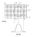
- FIGS. 4A and 4Bare a representation of the fields of view of an image sensor and a temperature sensor of the support substrate of FIG. 3 and a temperature profile of a field of view of the temperature sensor;
- FIG. 5is a top down view of an area to be imaged in accordance with an embodiment of the present disclosure
- FIGS. 6A and 6Bare an arrangement of an image sensor and a plurality of temperature sensors and corresponding fields of view
- FIGS. 7A and 7Bare an arrangement of an image sensor and a plurality of temperature sensors and corresponding fields of view
- FIGS. 8A and 8Bare an arrangement of an image sensor and a plurality of temperature sensors and corresponding fields of view
- FIGS. 9A and 9Bare an arrangement of a plurality of image sensors and a temperature sensors and corresponding fields of view.
- FIG. 10is a flowchart of a method of capturing and calibrating images.
- the present disclosureis directed to a system 100 that images a physical area or scene and outputs calibrated thermal images with accurate (absolute) temperature information about the imaged area.
- These thermal imagescan be used in a variety of contexts where accurate temperature is helpful.
- the health of crops, including water loss from the leavescan be observed with thermal imaging.
- evapotranspiration of a plantcan be determined by evaluating air temperature and thermal information of the leaves captured with an infrared sensor. Evapotranspiration represents the amount of water evaporating from the plant.
- a growercan evaluate the health and water needs of his/her plants by taking photographs, such as from an aerial position. The grower can then determine which of the plants to water. This avoids excess watering and allows for precise individual plant care.
- the system 100captures images from the ground or aerially from a manned or unmanned aerial vehicle 102 , such as an airplane or a drone as illustrated in FIG. 1 .
- the system 100includes a housing 101 that includes a support substrate 104 having at least one thermal or infrared image sensor 106 , at least one temperature sensor 108 , and a processor 110 as is illustrated in FIG. 2 .
- the housing 101includes openings that are aligned with the temperature sensor and the imaging sensor. Both the image sensor 106 and the temperature sensor 108 transmit and receive data to and from the processor 110 through electrical connections in or on the support substrate 104 (not shown).
- the support substratemay be a printed circuit board or other suitable support substrate that provides electrical connections between various devices on the substrate. The electrical connections may be in the substrate or through wires on the substrate or wires between the various components.
- Both the image sensor and the temperature sensorare positioned to image the same area. They are positioned adjacent to each other on the support substrate to ensure the images and data they capture overlap.
- Each of the image sensor and the temperature sensormay be packaged in separate packages, where each package may include a substrate.
- the substrate 104is a support, that may be active or passive, that supports both the image sensor and the temperature sensor in a way that allows the fields of view of each of the sensors to be directed to a same area.
- the substrate 104may be any number of shapes and sizes.
- the support substrate 104may be an integral piece in the housing 101 or may simply be the housing.
- the temperature sensormay be attached to a housing or package of the image sensor, such that the support substrate that supports the image sensor supports the temperature sensor by way of the image sensor.
- the processormay be a chip included on the support 104 that is coupled to both the image sensor and the temperature sensor.
- the processormay be part of a post-processing computer to which the housing 101 that includes the image sensor and the temperature sensor are coupled after an image taking session.
- the thermal image sensor and the temperature sensormay capture data on their own where there is no computer on board applying calibrations.
- the calibrations and processingmay also be performed in the cloud, a remote computing network that receives the collected data wirelessly from the image and temperature sensors or receives the data through a wired network once the housing 101 holding image and temperature sensors is coupled to a computer after the image capturing session.
- the temperature sensormay be coupled to the image sensor such that only the image sensor sends data to the processor. The image sensor would send both the temperature sensor data and the image sensor data.
- the image sensormay include the processor such that the temperature sensor data is received and processed by the image sensor processor.
- Each image sensor 106includes a housing 112 or some external packaging the houses an application specific integrated circuit 114 , an image sensor die 116 , and a lens 118 .
- the image sensor 106can include various die and packaging arrangements as specified by the particular implementation of the image sensor.
- the image sensor die 116is an infrared image sensor die that includes an array of sensors (or pixels) that respond to long wave infrared wavelengths and whose response is reflective of temperature of the imaged area.
- Data output by the image sensor 106may include non-calibrated information about temperature of the imaged area, i.e., the image sensor measures a relative difference of the temperatures in the imaged area and may provide a non-calibrated temperature output. This data primarily provides information about whether a specific item in the imaged area is hotter or colder than surrounding items.
- the image sensor 116 in the image sensor 106may include a plurality of microbolometers, which are devices that measure power of incident electromagnetic radiation in response to heating of a material that has a temperature-dependent electrical resistance. These microbolometers can be implemented as focal plan array sensors, which respond to these longer wavelengths. In particular, a microbolometric sensor detects infrared radiation in wavelengths between 7.5-14 microns as they interact with the material. As the infrared radiation hits the material it heats the material, which changes the material's electrical resistance. The change in resistance is measured and processed to create an image that represents thermal information about the area imaged. Such microbolometers may be uncooled thermal sensors.
- Uncooled thermal image sensorsoperate at ambient temperatures, but generate their own heat during operation.
- the measured change in resistance that corresponds to the received infrared radiationis a function of the temperature of the focal plane array.
- the output data, the thermal imagemust be adjusted accordingly if the operating temperature of the sensor is impacting the collected data.
- Some prior solutionsinclude incorporating complex shutter mechanisms that have known temperature within the image sensor. These shutter mechanisms are expensive, power hungry, and heavy. The shutter mechanisms are not easily incorporated into light-weight portable systems, such as the system 100 , which can be easily carried and utilized by an unmanned aerial vehicle.
- the image sensor of the present disclosure in conjunction with the temperature sensorwill provide accurate temperature information regarding the imaged area without the complex and heavy shutter mechanism.
- the temperature sensor 108outputs data about actual temperature of the area imaged by the image sensor.
- This systemis configured to process the data from the temperature sensor 108 and adjust the data output from the image sensor 106 to provide a user with data that represents accurate temperature of features in the imaged area.
- the systemis light-weight and cost effective for mobile applications.
- the systemcan be configured to be positioned away from the area to be imaged and carried by hand, a moving plane or other terrestrial or aerial vehicle.
- the temperature sensorincludes a thermopile, a pyrometer, an infrared (long wave) photodiode, or any suitable non-contact remote temperature sensing device.
- the temperature sensormay be a single-pixel thermopile.
- a thermopileis an electronic device that converts thermal energy into electrical output.
- the temperature sensorwill output a single value that represents an average of the actual temperature across the field of view of the temperature sensor. This value is in absolute units, such as degrees Celsius.
- the thermopilemay have a lens that provides a more uniform field of view.
- each of the image sensorsmay include a manually or automatically adjustable lens.
- FIG. 3is a simplified side view of the substrate 104 having the image sensor 106 and the temperature sensor 108 .
- a field of view 120 of the image sensor 106corresponds to an array of pixels 130 that gather thermal information about the imaged area; this will be referred to as a thermal image 121 .
- the array of pixels 130forms the thermal image 121 having a rectangular representation of the imaged area, such as 640 pixels wide by 480 pixels tall.
- the field of view 120 of the image sensoris larger than a field of view 122 of the temperature sensor 108 .
- the field of view 122 of the temperature sensor 108is completely overlapping with and positioned within the field of view 120 of the image sensor.
- the field of view 122 of the temperature sensormaybe aligned with an outer edge 123 , such that a portion of the field of view 122 extends past the edge of the pixels.
- the field of view 122is shifted to the right from a center of the field of view of the imaging sensor as the temperature sensor 108 is positioned to the right of the image sensor on the substrate 104 .
- a center point 124 (on a center line 127 ) of the field of view 122 of the temperature sensor 108is shifted from a center line 126 of the field of view of the image sensor.
- the single temperature sensor 108is used to calibrate the entire thermal image 121 .
- Each pixel of the thermal image 121has a digital number that, in conjunction, with the other digital numbers indicates how hot or cold that pixel is in comparison to other pixels.
- the systemeither during operation or pre-shipment to a user, determines the pixels in each image that correspond to the field of view 122 of the temperature sensor. This includes identifying the pixels that correspond with a boundary of the field of view 122 and a pixel or group of pixels of the thermal image 121 that corresponds to the center point 124 of the temperature sensor.
- the temperature sensor 108outputs an actual temperature that represents an average temperature of the items in the thermal image that are within the temperature sensor's field of view 122 .
- Each of the pixels of the thermal image that are within the field of view 122is analyzed with respect to the actual temperature to get a weighted average.
- the center pixelwhich has an x and y value, corresponds to the center point 124 of the field of view 122 , is given a weight of 1.
- the pixels at the boundary of the field of view 122are given a weight of 0. Moving radially from the center pixel to the boundary pixels, each pixel will be given a weight between 1 and 0, decreasing from 1 to 0 as the pixels are further from the center pixel. For example, see FIG. 4B .
- This weighted averageis then used to calibrate the entire thermal image to create a calibrated thermal image that provides accurate temperature information about the imaged scene.
- the field of view of the temperature sensoris illustrated as circular, however other shapes of the field of view, which represent the temperature information gathered are envisioned.
- the field of viewdoes not have rigid boundaries.
- An outer-most edgemay be defined by the system to utilize the most accurate data returned by the temperature sensor module. As in FIG. 4 , pixels near the boundary of the field of view are given less weight as they are less accurately representative of the temperature.
- the thermal image sensoralone does not provide temperature data in degrees, which is very useful information for a user analyzing the data. Knowing how hot or how cold an item of the imaged area actually is can provide the user with actionable data. For example, if the imaged area is an orchard the user can determine specific watering patterns to match the needs of individual or groups of plants. Orchards are often organized in rows and columns of plants and trees such that from an aerial perspective, the plants are easily imaged and analyzed. For example, see FIG. 5 , which includes an orchard 500 having a plurality of trees 502 .
- temperatureis indicative of stress of each plant or tree.
- the systemwill capture a plurality of sequential images of the area, such as the orchard.
- a drone or other aerial vehicle 504 carrying the systemcan fly a route 506 over the orchard.
- the system 100will capture thermal images 508 either at a selected rate or frequency or simply sequentially throughout the flight.
- the adjacent images 508will include overlapping subject matter regarding the scene.
- the systemwill simultaneously be gathering thermal information about the actual temperature of the orchard associated with each image.
- the pixels of the thermal imageare evaluated to determine actual temperature information for each pixel based on the temperature information.
- a calibration valueis determined based on the subset of the pixels that correspond to the temperature sensor and then the calibration value is used to calibrate the whole thermal image.
- a calibrated thermal imageis created.
- the calibrated thermal imagemay be directly output to the user.
- each of the thermal images 508are thermally calibrated with the temperature information to generate a plurality of calibrated thermal images.
- the plurality of imagesmay be stitched together to create an image that represents the actual temperature information about an area, such as the whole orchard or a specific tree in the orchard.
- FIGS. 6A-8Bare examples of arrangements of a system 200 having an image sensor 202 positioned adjacent to a plurality of temperature sensors 204 a - 204 h on a support 206 and corresponding fields of view for the image sensor 210 and the temperature sensors 212 a - 212 h .
- the supportwill be integrated within a housing that includes openings aligned with each of the image sensors and the plurality of temperature sensors.
- the supportalso includes a processor 208 that is electrically coupled to the image sensor and the temperature sensors.
- the processorcontrols operation, including timing and duration for images captured by the image sensor and the temperature sensors.
- the processor 208may include memory or a stand-alone memory may be housed on the support.
- the temperature information and the thermal imagesare either processed in real time to output the calibrated thermal image or stored in memory and processed at a later time.
- FIG. 6Aincludes the image sensor 202 centrally positioned on the support 206 and four temperature sensors 204 a - 204 d positioned at corners of the image sensor.
- the fields of view 212 a - 212 d of the temperature sensor modules shown in FIG. 6Bcorrespond to specific, distinct regions of the field of view 210 of the image from the image sensor.
- a size of the field of view of each temperature sensorcan be selected for a particular implementation.
- the field of view 212 a corresponding to the temperature sensor 204 amay be larger than illustrated to cover a larger portion of the array of pixels associated with the field of view 210 of the image sensor.
- the systemis configured to determine a calibration value, such as a weighted average for each of the fields of view 212 a - 212 d .
- the calibration valuemay then be applied to a quadrant of the pixels of the image from the image sensor within which the field of view is positioned.
- a final calibration valuemay be determined from the four calibration values such that the thermal image from the image sensor is calibrated with the final calibration value.
- the four calibration values that correspond to the weighted average generated for the four fields of view of the four temperature sensorsmay be averaged together or may be used to generate a regression-based calibration curve. This collective or final calibration value is then applied to every pixel of the thermal image to generate the calibrated thermal image.
- FIG. 7Ais a different arrangement of the system 200 including five temperature sensors, the four previously discussed in FIG. 6A and a fifth temperature sensor 204 e positioned between the first temperature sensor 204 a and the second temperature sensor 204 b .
- the fifth temperature sensor 204 emay have a larger field of view 212 e and may be positioned to have the field of view 212 e cover a central area of the field of view 210 not covered by the other fields of view 212 a - 212 d.
- FIG. 8Ais another arrangement of the system 200 including eight temperature sensors 204 a - 204 h positioned around the image sensor 202 .
- FIG. 8Billustrates the various fields of view 212 a - 212 h of the temperature sensors.
- the temperature sensors 204 g and 204 ehave wider fields of view than the temperatures sensors 204 a , 204 b , 204 c , 204 d , 204 f , and 204 h .
- the field of view sizemay be selected to maximize the area of the thermal image that corresponds to a field of view of the temperature sensor. Any number of temperature sensors may be included to give more accurate temperature information to the system for use in calibration of the image ultimately provided to the user.
- the field of view of the temperature sensorsmay overlap.
- the weighted averages from each field of viewmay be compared with each other to confirm the actual temperature of the scene. For example, the system could determine the temperature associated with the portion of the field of view that is overlapping with an adjacent field of view. The values that represent each of the overlapping sections can be compared to determine if they are reading a similar temperature. If they are slightly off, the system generates an offset that calibrates the calibration value before calibrating the whole thermal image. This gives the system more precise temperature information, which results in a more precise calibrated thermal image to provide to the user or to further process.
- FIG. 9Ais an alternative arrangement of a system 300 including a first image sensor 302 , a second image sensor 304 , a third image sensor 306 , and a fourth image sensor 308 , which are positioned on a substrate 310 around a temperature sensor 312 .
- a processor 314is positioned on the substrate 310 and in electrical communication with the image sensors and the temperature sensor.
- Each image sensormay include a different lens and a different field of view. This provides a user with flexibility regarding an amount of zoom available from the system. For example, if the user is operating and reviewing data in real time, the user may identify a portion of the area for which they want more information regarding temperature. The system can then zoom in on the portion using a different one of the image sensors that has a different field of view.
- the image sensorsmay be operated sequentially or in a pattern such that during an imaging phase a plurality of images having different fields of view are gathered and later processed.
- the temperature sensorgathers temperature information during the whole imaging phase and based on time and duration information, the images from the different image sensors can be matched and calibrated from the temperature sensor data.
- FIG. 9Bincludes four images.
- a first image 316corresponds to the first image sensor 302 having a first zoom.
- a second image 318corresponds to the second image sensor 304 having a second zoom. The second image 318 captures more of the area than the first image.
- a third image 320corresponds to the third image sensor 306 having a third zoom. The third image 320 captures a narrower portion of the area than the first and second image.
- a fourth image 322corresponds to the fourth image sensor 308 and has a fourth zoom.
- a field of view 324 of the temperature sensor 312overlaps a different portion of each image as a relative position between the sensor and each image sensor is different.
- Each of the thermal images gathered from each of the image sensorscan be calibrated with the temperature information gathered by the temperature sensor.
- the calibration value determined from the temperature information and the pixels of the thermal image that correspond to the field of view of the temperature sensorcan be compared to make the temperature information output with the calibrated thermal image more accurate.
- the image sensor or modules and the temperature sensor or modulesare aligned on the support substrate to ensure overlap of the field of views of the modules.
- the image sensor 106 and temperature sensor 108 of FIG. 3will be discussed, however, the discussion applies to all examples and iterations discussed in this application.
- the temperature sensormay be slightly angled off a first surface 128 to adjust a position of the field of view 122 with respect to the field of view 120 of the image sensor. For example, as noted above, as a result of being physically next to the image sensor, the field of view of the temperature sensor is shifted from the center line 126 of the field of view of the image sensor. To better align the center point 124 with the center line 126 , one or both of the modules may be angled with respect to the first surface of the substrate, i.e. a bottom surface of the module may have a first portion closer to the substrate than a second portion.
- the temperature sensor or the image sensorwith respect to the first surface of the substrate as the modules will be physically very close, resulting in overlap of their fields of view.
- the scene or area being imagedis typically at a large distance from the system as compared to a distance between the image sensor and the temperature sensor.
- incorporating the temperature sensor within this systemcan provide information about the vignette effect of the image sensor.
- FIG. 10is a flowchart of a method of the present disclosure.
- the methodincludes capturing a thermal image of an area with an image sensor in step 400 .
- the capturingincludes capturing the thermal images on a specific clock cycle, which can be controlled by a clock of the system.
- the methodalso includes capturing temperature information in step 402 , which may also be captured or stored in accordance with the clock cycle.
- the thermal images and the temperature informationcan be matched in post-processing by the clock cycle data.
- step 404includes matching each thermal image with the corresponding temperature information based on duration and time information.
- Step 406includes determining a calibration value from the temperature information and from the specific pixels of the thermal image that overlap with the field of view of the temperature sensor.
- Step 408includes applying the calibration value to the thermal image to change the digital number of each pixel to represent a temperature value, such as in degrees Celsius.
- the methodthen includes outputting a calibrated thermal image representative of actual temperature of the scene in step 410 .
- Each pixelwill have a temperature value so that when viewed as a whole the various temperatures across the imaged area will be visible.
- This processcan be performed on a subset of the thermal images such that a calibration value may be applied to a sequence of thermal images or the process can be applied to every single thermal image gathered by the system.
Landscapes
- Engineering & Computer Science (AREA)
- Multimedia (AREA)
- Signal Processing (AREA)
- Health & Medical Sciences (AREA)
- Aviation & Aerospace Engineering (AREA)
- Biomedical Technology (AREA)
- General Health & Medical Sciences (AREA)
- Microelectronics & Electronic Packaging (AREA)
- Toxicology (AREA)
- Mechanical Engineering (AREA)
- Remote Sensing (AREA)
- Radiation Pyrometers (AREA)
- General Physics & Mathematics (AREA)
- Theoretical Computer Science (AREA)
- Physics & Mathematics (AREA)
- Computer Vision & Pattern Recognition (AREA)
Abstract
Description
Claims (14)
Priority Applications (1)
| Application Number | Priority Date | Filing Date | Title |
|---|---|---|---|
| US15/620,627US10518900B2 (en) | 2016-06-14 | 2017-06-12 | Thermal calibration of an infrared image sensor |
Applications Claiming Priority (2)
| Application Number | Priority Date | Filing Date | Title |
|---|---|---|---|
| US201662350116P | 2016-06-14 | 2016-06-14 | |
| US15/620,627US10518900B2 (en) | 2016-06-14 | 2017-06-12 | Thermal calibration of an infrared image sensor |
Publications (2)
| Publication Number | Publication Date |
|---|---|
| US20170358105A1 US20170358105A1 (en) | 2017-12-14 |
| US10518900B2true US10518900B2 (en) | 2019-12-31 |
Family
ID=60574005
Family Applications (1)
| Application Number | Title | Priority Date | Filing Date |
|---|---|---|---|
| US15/620,627Active2037-11-14US10518900B2 (en) | 2016-06-14 | 2017-06-12 | Thermal calibration of an infrared image sensor |
Country Status (1)
| Country | Link |
|---|---|
| US (1) | US10518900B2 (en) |
Cited By (1)
| Publication number | Priority date | Publication date | Assignee | Title |
|---|---|---|---|---|
| US20220146320A1 (en)* | 2020-04-03 | 2022-05-12 | Huawei Technologies Co., Ltd. | Temperature Measurement Method and Electronic Device |
Families Citing this family (6)
| Publication number | Priority date | Publication date | Assignee | Title |
|---|---|---|---|---|
| US11781890B2 (en)* | 2017-12-29 | 2023-10-10 | Intel Corporation | Method, a circuit and a system for environmental sensing |
| CN109741400B (en)* | 2018-12-11 | 2020-08-18 | 东南大学 | Device and method for joint calibration of industrial binocular camera and infrared thermal imager |
| CN112449174B (en)* | 2019-08-28 | 2022-11-25 | 浙江宇视科技有限公司 | Imaging equipment calibration method and device and imaging equipment |
| EP3885725B1 (en) | 2020-03-23 | 2022-01-12 | Axis AB | Method, device, and system for temperature calibration and determination of a temperature in a scene |
| US11307098B2 (en) | 2020-03-27 | 2022-04-19 | Ecb Consulting Llc | Systems and approaches for obtaining temperature measurements using thermal imaging |
| CN120593905A (en)* | 2025-08-06 | 2025-09-05 | 上海海能信息科技股份有限公司 | A temperature monitoring method based on online dynamic calibration |
Citations (67)
| Publication number | Priority date | Publication date | Assignee | Title |
|---|---|---|---|---|
| US7056012B2 (en) | 2002-10-03 | 2006-06-06 | Extech Instruments Corporation | Multimeter with non-contact temperature measurement |
| US7111981B2 (en) | 2004-01-06 | 2006-09-26 | Extech Instruments Corporation | Instrument for non-contact infrared temperature measurement combined with tachometer functions |
| US7163336B2 (en) | 2003-08-04 | 2007-01-16 | Extech Instruments Corporation | Instrument for non-contact infrared temperature measurement having current clamp meter functions |
| US7168316B2 (en) | 2004-01-20 | 2007-01-30 | Extech Instruments Corporation | Humidity meter with non-contact temperature measurement |
| US7452127B2 (en) | 2005-07-25 | 2008-11-18 | Extech Instruments Corporation | Anemometer with non-contact temperature measurement |
| US20090256077A1 (en)* | 2008-04-15 | 2009-10-15 | Solar Turbines Incorporated | Health monitoring through a correlation of thermal images and temperature data |
| US20110261207A1 (en) | 2010-04-23 | 2011-10-27 | Flir Systems Ab | Infrared resolution and contrast enhancement with fusion |
| US8208026B2 (en) | 2009-03-02 | 2012-06-26 | Flir Systems, Inc. | Systems and methods for processing infrared images |
| US20120262584A1 (en) | 2010-04-23 | 2012-10-18 | Flir Systems Ab | Infrared resolution and contrast enhancement with fusion |
| US20130173435A1 (en) | 2011-12-16 | 2013-07-04 | Thomas Michael Cozad, JR. | Systems and methods for managing product location information |
| US20130253551A1 (en) | 2012-02-07 | 2013-09-26 | Edward M. Boyle, M.D. | Phlebectomy device and system |
| US20130250125A1 (en) | 2009-03-02 | 2013-09-26 | Flir Systems, Inc. | Thermal image frame capture using de-aligned sensor array |
| US20130258111A1 (en) | 2009-03-02 | 2013-10-03 | Flir Systems, Inc. | Device attachment with infrared imaging sensor |
| US20130278771A1 (en) | 2011-06-10 | 2013-10-24 | Flir Systems, Inc. | Systems and methods for monitoring vehicle wheel assembly |
| US20130300875A1 (en) | 2010-04-23 | 2013-11-14 | Flir Systems Ab | Correction of image distortion in ir imaging |
| US20130314536A1 (en) | 2009-03-02 | 2013-11-28 | Flir Systems, Inc. | Systems and methods for monitoring vehicle occupants |
| US20130321637A1 (en) | 2009-03-02 | 2013-12-05 | Flir Systems, Inc. | Monitor and control systems and methods for occupant safety and energy efficiency of structures |
| US20130342691A1 (en) | 2009-06-03 | 2013-12-26 | Flir Systems, Inc. | Infant monitoring systems and methods using thermal imaging |
| US20140085482A1 (en) | 2010-04-23 | 2014-03-27 | Flir Systems, Inc. | Hybrid infrared sensor array having heterogeneous infrared sensors |
| US20140092256A1 (en) | 2010-04-23 | 2014-04-03 | Flir Systems, Inc. | Infrared imager with integrated metal layers |
| US20140112537A1 (en) | 2011-06-10 | 2014-04-24 | Flir Systems, Inc. | Systems and methods for intelligent monitoring of thoroughfares using thermal imaging |
| US8727608B2 (en) | 2003-09-04 | 2014-05-20 | Flir Systems, Inc. | Moisture meter with non-contact infrared thermometer |
| US20140139643A1 (en) | 2009-06-03 | 2014-05-22 | Flir Systems, Inc. | Imager with array of multiple infrared imaging modules |
| US8749635B2 (en) | 2009-06-03 | 2014-06-10 | Flir Systems, Inc. | Infrared camera systems and methods for dual sensor applications |
| US20140168445A1 (en) | 2009-06-03 | 2014-06-19 | Flir Systems, Inc. | Systems and methods of suppressing sky regions in images |
| US20140168433A1 (en) | 2009-06-03 | 2014-06-19 | Flir Systems, Inc. | Systems and methods for monitoring power systems |
| US8766808B2 (en) | 2010-03-09 | 2014-07-01 | Flir Systems, Inc. | Imager with multiple sensor arrays |
| US20140184807A1 (en) | 2010-04-23 | 2014-07-03 | Flir Systems, Inc. | Segmented focal plane array architecture |
| US20140232875A1 (en) | 2011-06-10 | 2014-08-21 | Flir Systems, Inc. | Determination of an absolute radiometric value using blocked infrared sensors |
| US20140253735A1 (en) | 2003-09-04 | 2014-09-11 | Flir Systems, Inc. | Device attachment with infrared imaging sensor |
| US20150109454A1 (en) | 2009-06-03 | 2015-04-23 | Flir Systems Ab | Facilitating analysis and interpretation of associated visible light and infrared (ir) image information |
| US9058653B1 (en) | 2011-06-10 | 2015-06-16 | Flir Systems, Inc. | Alignment of visible light sources based on thermal images |
| US20150172545A1 (en) | 2013-10-03 | 2015-06-18 | Flir Systems, Inc. | Situational awareness by compressed display of panoramic views |
| US9143703B2 (en) | 2011-06-10 | 2015-09-22 | Flir Systems, Inc. | Infrared camera calibration techniques |
| US20150288892A1 (en) | 2009-03-02 | 2015-10-08 | Flir Systems, Inc. | Device attachment with infrared imaging sensor |
| US20150296146A1 (en) | 2011-06-10 | 2015-10-15 | Flir Systems, Inc. | Electrical cabinet infrared monitor systems and methods |
| US20150312488A1 (en) | 2011-06-10 | 2015-10-29 | Flir Systems, Inc. | Techniques to compensate for calibration drifts in infrared imaging devices |
| US20150312490A1 (en) | 2011-06-10 | 2015-10-29 | Flir Systems, Inc. | Infrared focal plane array heat spreaders |
| US20150312489A1 (en) | 2009-03-02 | 2015-10-29 | Flir Systems, Inc. | Anomalous pixel detection |
| US20150319379A1 (en) | 2011-06-10 | 2015-11-05 | Flir Systems, Inc. | Infrared detector array with selectable pixel binning systems and methods |
| US20150319378A1 (en) | 2011-06-10 | 2015-11-05 | Flir Systems, Inc. | Infrared imaging device having a shutter |
| US9208542B2 (en) | 2009-03-02 | 2015-12-08 | Flir Systems, Inc. | Pixel-wise noise reduction in thermal images |
| US9207708B2 (en) | 2010-04-23 | 2015-12-08 | Flir Systems, Inc. | Abnormal clock rate detection in imaging sensor arrays |
| US20150358560A1 (en) | 2009-03-02 | 2015-12-10 | Flir Systems, Inc. | Compact multi-spectrum imaging with fusion |
| US20150379361A1 (en) | 2011-06-10 | 2015-12-31 | Flir Systems, Inc. | Image-assisted remote control vehicle systems and methods |
| US9235023B2 (en) | 2011-06-10 | 2016-01-12 | Flir Systems, Inc. | Variable lens sleeve spacer |
| US9237284B2 (en) | 2009-03-02 | 2016-01-12 | Flir Systems, Inc. | Systems and methods for processing infrared images |
| US9235876B2 (en) | 2009-03-02 | 2016-01-12 | Flir Systems, Inc. | Row and column noise reduction in thermal images |
| US20160074724A1 (en) | 2009-06-03 | 2016-03-17 | Flir Systems, Inc. | Thermal-assisted golf rangefinder systems and methods |
| US9292909B2 (en) | 2009-06-03 | 2016-03-22 | Flir Systems, Inc. | Selective image correction for infrared imaging devices |
| US20160156880A1 (en) | 2009-06-03 | 2016-06-02 | Flir Systems, Inc. | Durable compact multisensor observation devices |
| US20160224055A1 (en) | 2010-04-23 | 2016-08-04 | Flir Systems, Inc. | Abnormal clock rate detection in imaging sensor arrays |
| USD765081S1 (en) | 2012-05-25 | 2016-08-30 | Flir Systems, Inc. | Mobile communications device attachment with camera |
| US9451183B2 (en) | 2009-03-02 | 2016-09-20 | Flir Systems, Inc. | Time spaced infrared image enhancement |
| US9473681B2 (en) | 2011-06-10 | 2016-10-18 | Flir Systems, Inc. | Infrared camera system housing with metalized surface |
| US20160316119A1 (en) | 2009-03-02 | 2016-10-27 | Flir Systems, Inc. | Techniques for device attachment with dual band imaging sensor |
| US20160316154A1 (en) | 2014-01-05 | 2016-10-27 | Flir Systems, Inc. | Device attachment with dual band imaging sensor |
| US9509924B2 (en) | 2011-06-10 | 2016-11-29 | Flir Systems, Inc. | Wearable apparatus with integrated infrared imaging module |
| US9521289B2 (en) | 2011-06-10 | 2016-12-13 | Flir Systems, Inc. | Line based image processing and flexible memory system |
| US9517679B2 (en) | 2009-03-02 | 2016-12-13 | Flir Systems, Inc. | Systems and methods for monitoring vehicle occupants |
| US20170088098A1 (en) | 2009-03-02 | 2017-03-30 | Flir Systems, Inc. | Systems and methods for monitoring vehicle occupants |
| US9635285B2 (en) | 2009-03-02 | 2017-04-25 | Flir Systems, Inc. | Infrared imaging enhancement with fusion |
| US9674458B2 (en) | 2009-06-03 | 2017-06-06 | Flir Systems, Inc. | Smart surveillance camera systems and methods |
| US9706139B2 (en) | 2011-06-10 | 2017-07-11 | Flir Systems, Inc. | Low power and small form factor infrared imaging |
| US9706137B2 (en) | 2011-06-10 | 2017-07-11 | Flir Systems, Inc. | Electrical cabinet infrared monitor |
| US9716843B2 (en) | 2009-06-03 | 2017-07-25 | Flir Systems, Inc. | Measurement device for electrical installations and related methods |
| US9723227B2 (en) | 2011-06-10 | 2017-08-01 | Flir Systems, Inc. | Non-uniformity correction techniques for infrared imaging devices |
- 2017
- 2017-06-12USUS15/620,627patent/US10518900B2/enactiveActive
Patent Citations (84)
| Publication number | Priority date | Publication date | Assignee | Title |
|---|---|---|---|---|
| US7192186B2 (en) | 2002-10-03 | 2007-03-20 | Extech Instruments Corporation | Multimeter with non-contact temperature measurement |
| US7056012B2 (en) | 2002-10-03 | 2006-06-06 | Extech Instruments Corporation | Multimeter with non-contact temperature measurement |
| US7163336B2 (en) | 2003-08-04 | 2007-01-16 | Extech Instruments Corporation | Instrument for non-contact infrared temperature measurement having current clamp meter functions |
| US8727608B2 (en) | 2003-09-04 | 2014-05-20 | Flir Systems, Inc. | Moisture meter with non-contact infrared thermometer |
| US20140253735A1 (en) | 2003-09-04 | 2014-09-11 | Flir Systems, Inc. | Device attachment with infrared imaging sensor |
| US7111981B2 (en) | 2004-01-06 | 2006-09-26 | Extech Instruments Corporation | Instrument for non-contact infrared temperature measurement combined with tachometer functions |
| US7168316B2 (en) | 2004-01-20 | 2007-01-30 | Extech Instruments Corporation | Humidity meter with non-contact temperature measurement |
| US7452127B2 (en) | 2005-07-25 | 2008-11-18 | Extech Instruments Corporation | Anemometer with non-contact temperature measurement |
| US20090256077A1 (en)* | 2008-04-15 | 2009-10-15 | Solar Turbines Incorporated | Health monitoring through a correlation of thermal images and temperature data |
| US20130321637A1 (en) | 2009-03-02 | 2013-12-05 | Flir Systems, Inc. | Monitor and control systems and methods for occupant safety and energy efficiency of structures |
| US9235876B2 (en) | 2009-03-02 | 2016-01-12 | Flir Systems, Inc. | Row and column noise reduction in thermal images |
| US20170088098A1 (en) | 2009-03-02 | 2017-03-30 | Flir Systems, Inc. | Systems and methods for monitoring vehicle occupants |
| US20170078590A1 (en) | 2009-03-02 | 2017-03-16 | Flir Systems, Inc. | Time spaced infrared image enhancement |
| US9517679B2 (en) | 2009-03-02 | 2016-12-13 | Flir Systems, Inc. | Systems and methods for monitoring vehicle occupants |
| US20130250125A1 (en) | 2009-03-02 | 2013-09-26 | Flir Systems, Inc. | Thermal image frame capture using de-aligned sensor array |
| US20130258111A1 (en) | 2009-03-02 | 2013-10-03 | Flir Systems, Inc. | Device attachment with infrared imaging sensor |
| US20160316119A1 (en) | 2009-03-02 | 2016-10-27 | Flir Systems, Inc. | Techniques for device attachment with dual band imaging sensor |
| US9451183B2 (en) | 2009-03-02 | 2016-09-20 | Flir Systems, Inc. | Time spaced infrared image enhancement |
| US20150312489A1 (en) | 2009-03-02 | 2015-10-29 | Flir Systems, Inc. | Anomalous pixel detection |
| US20130314536A1 (en) | 2009-03-02 | 2013-11-28 | Flir Systems, Inc. | Systems and methods for monitoring vehicle occupants |
| US20150288892A1 (en) | 2009-03-02 | 2015-10-08 | Flir Systems, Inc. | Device attachment with infrared imaging sensor |
| US9208542B2 (en) | 2009-03-02 | 2015-12-08 | Flir Systems, Inc. | Pixel-wise noise reduction in thermal images |
| US20150358560A1 (en) | 2009-03-02 | 2015-12-10 | Flir Systems, Inc. | Compact multi-spectrum imaging with fusion |
| US8780208B2 (en) | 2009-03-02 | 2014-07-15 | Flir Systems, Inc. | Systems and methods for processing infrared images |
| US9635285B2 (en) | 2009-03-02 | 2017-04-25 | Flir Systems, Inc. | Infrared imaging enhancement with fusion |
| US8208026B2 (en) | 2009-03-02 | 2012-06-26 | Flir Systems, Inc. | Systems and methods for processing infrared images |
| US9237284B2 (en) | 2009-03-02 | 2016-01-12 | Flir Systems, Inc. | Systems and methods for processing infrared images |
| US20150109454A1 (en) | 2009-06-03 | 2015-04-23 | Flir Systems Ab | Facilitating analysis and interpretation of associated visible light and infrared (ir) image information |
| US9083897B2 (en) | 2009-06-03 | 2015-07-14 | Flir Systems, Inc. | Infrared camera systems and methods for dual sensor applications |
| US20140168433A1 (en) | 2009-06-03 | 2014-06-19 | Flir Systems, Inc. | Systems and methods for monitoring power systems |
| US9716843B2 (en) | 2009-06-03 | 2017-07-25 | Flir Systems, Inc. | Measurement device for electrical installations and related methods |
| US20140139643A1 (en) | 2009-06-03 | 2014-05-22 | Flir Systems, Inc. | Imager with array of multiple infrared imaging modules |
| US20160074724A1 (en) | 2009-06-03 | 2016-03-17 | Flir Systems, Inc. | Thermal-assisted golf rangefinder systems and methods |
| US20150085133A1 (en) | 2009-06-03 | 2015-03-26 | Flir Systems, Inc. | Wearable imaging devices, systems, and methods |
| US9292909B2 (en) | 2009-06-03 | 2016-03-22 | Flir Systems, Inc. | Selective image correction for infrared imaging devices |
| US20140168445A1 (en) | 2009-06-03 | 2014-06-19 | Flir Systems, Inc. | Systems and methods of suppressing sky regions in images |
| US8749635B2 (en) | 2009-06-03 | 2014-06-10 | Flir Systems, Inc. | Infrared camera systems and methods for dual sensor applications |
| US20130342691A1 (en) | 2009-06-03 | 2013-12-26 | Flir Systems, Inc. | Infant monitoring systems and methods using thermal imaging |
| US20160156880A1 (en) | 2009-06-03 | 2016-06-02 | Flir Systems, Inc. | Durable compact multisensor observation devices |
| US9674458B2 (en) | 2009-06-03 | 2017-06-06 | Flir Systems, Inc. | Smart surveillance camera systems and methods |
| US8766808B2 (en) | 2010-03-09 | 2014-07-01 | Flir Systems, Inc. | Imager with multiple sensor arrays |
| US9171361B2 (en) | 2010-04-23 | 2015-10-27 | Flir Systems Ab | Infrared resolution and contrast enhancement with fusion |
| US20140092256A1 (en) | 2010-04-23 | 2014-04-03 | Flir Systems, Inc. | Infrared imager with integrated metal layers |
| US20110261207A1 (en) | 2010-04-23 | 2011-10-27 | Flir Systems Ab | Infrared resolution and contrast enhancement with fusion |
| US9706138B2 (en) | 2010-04-23 | 2017-07-11 | Flir Systems, Inc. | Hybrid infrared sensor array having heterogeneous infrared sensors |
| WO2011131758A1 (en) | 2010-04-23 | 2011-10-27 | Flir Systems Ab | Infrared resolution and contrast enhancement with fusion |
| US20120262584A1 (en) | 2010-04-23 | 2012-10-18 | Flir Systems Ab | Infrared resolution and contrast enhancement with fusion |
| US8520970B2 (en) | 2010-04-23 | 2013-08-27 | Flir Systems Ab | Infrared resolution and contrast enhancement with fusion |
| US20170004609A1 (en) | 2010-04-23 | 2017-01-05 | Flir Systems Ab | Infrared resolution and contrast enhancement with fusion |
| US8565547B2 (en) | 2010-04-23 | 2013-10-22 | Flir Systems Ab | Infrared resolution and contrast enhancement with fusion |
| US9207708B2 (en) | 2010-04-23 | 2015-12-08 | Flir Systems, Inc. | Abnormal clock rate detection in imaging sensor arrays |
| US9471970B2 (en) | 2010-04-23 | 2016-10-18 | Flir Systems Ab | Infrared resolution and contrast enhancement with fusion |
| US20160224055A1 (en) | 2010-04-23 | 2016-08-04 | Flir Systems, Inc. | Abnormal clock rate detection in imaging sensor arrays |
| US20130300875A1 (en) | 2010-04-23 | 2013-11-14 | Flir Systems Ab | Correction of image distortion in ir imaging |
| US20140184807A1 (en) | 2010-04-23 | 2014-07-03 | Flir Systems, Inc. | Segmented focal plane array architecture |
| US20140085482A1 (en) | 2010-04-23 | 2014-03-27 | Flir Systems, Inc. | Hybrid infrared sensor array having heterogeneous infrared sensors |
| US20150379361A1 (en) | 2011-06-10 | 2015-12-31 | Flir Systems, Inc. | Image-assisted remote control vehicle systems and methods |
| US20150312490A1 (en) | 2011-06-10 | 2015-10-29 | Flir Systems, Inc. | Infrared focal plane array heat spreaders |
| US20140112537A1 (en) | 2011-06-10 | 2014-04-24 | Flir Systems, Inc. | Systems and methods for intelligent monitoring of thoroughfares using thermal imaging |
| US9235023B2 (en) | 2011-06-10 | 2016-01-12 | Flir Systems, Inc. | Variable lens sleeve spacer |
| US20150296146A1 (en) | 2011-06-10 | 2015-10-15 | Flir Systems, Inc. | Electrical cabinet infrared monitor systems and methods |
| US9723227B2 (en) | 2011-06-10 | 2017-08-01 | Flir Systems, Inc. | Non-uniformity correction techniques for infrared imaging devices |
| US20130278771A1 (en) | 2011-06-10 | 2013-10-24 | Flir Systems, Inc. | Systems and methods for monitoring vehicle wheel assembly |
| US9473681B2 (en) | 2011-06-10 | 2016-10-18 | Flir Systems, Inc. | Infrared camera system housing with metalized surface |
| US20140232875A1 (en) | 2011-06-10 | 2014-08-21 | Flir Systems, Inc. | Determination of an absolute radiometric value using blocked infrared sensors |
| US9058653B1 (en) | 2011-06-10 | 2015-06-16 | Flir Systems, Inc. | Alignment of visible light sources based on thermal images |
| US9723228B2 (en) | 2011-06-10 | 2017-08-01 | Flir Systems, Inc. | Infrared camera system architectures |
| US9509924B2 (en) | 2011-06-10 | 2016-11-29 | Flir Systems, Inc. | Wearable apparatus with integrated infrared imaging module |
| US9521289B2 (en) | 2011-06-10 | 2016-12-13 | Flir Systems, Inc. | Line based image processing and flexible memory system |
| US9143703B2 (en) | 2011-06-10 | 2015-09-22 | Flir Systems, Inc. | Infrared camera calibration techniques |
| US9538038B2 (en) | 2011-06-10 | 2017-01-03 | Flir Systems, Inc. | Flexible memory systems and methods |
| US20150319378A1 (en) | 2011-06-10 | 2015-11-05 | Flir Systems, Inc. | Infrared imaging device having a shutter |
| US20150319379A1 (en) | 2011-06-10 | 2015-11-05 | Flir Systems, Inc. | Infrared detector array with selectable pixel binning systems and methods |
| US9716844B2 (en) | 2011-06-10 | 2017-07-25 | Flir Systems, Inc. | Low power and small form factor infrared imaging |
| US20170208260A1 (en) | 2011-06-10 | 2017-07-20 | Flir Systems, Inc. | Wearable apparatus with integrated infrared imaging module |
| US9247131B2 (en) | 2011-06-10 | 2016-01-26 | Flir Systems, Inc. | Alignment of visible light sources based on thermal images |
| US9706139B2 (en) | 2011-06-10 | 2017-07-11 | Flir Systems, Inc. | Low power and small form factor infrared imaging |
| US9706137B2 (en) | 2011-06-10 | 2017-07-11 | Flir Systems, Inc. | Electrical cabinet infrared monitor |
| US20150312488A1 (en) | 2011-06-10 | 2015-10-29 | Flir Systems, Inc. | Techniques to compensate for calibration drifts in infrared imaging devices |
| US20130173435A1 (en) | 2011-12-16 | 2013-07-04 | Thomas Michael Cozad, JR. | Systems and methods for managing product location information |
| US20130253551A1 (en) | 2012-02-07 | 2013-09-26 | Edward M. Boyle, M.D. | Phlebectomy device and system |
| USD765081S1 (en) | 2012-05-25 | 2016-08-30 | Flir Systems, Inc. | Mobile communications device attachment with camera |
| US20150172545A1 (en) | 2013-10-03 | 2015-06-18 | Flir Systems, Inc. | Situational awareness by compressed display of panoramic views |
| US20160316154A1 (en) | 2014-01-05 | 2016-10-27 | Flir Systems, Inc. | Device attachment with dual band imaging sensor |
Cited By (2)
| Publication number | Priority date | Publication date | Assignee | Title |
|---|---|---|---|---|
| US20220146320A1 (en)* | 2020-04-03 | 2022-05-12 | Huawei Technologies Co., Ltd. | Temperature Measurement Method and Electronic Device |
| US12259278B2 (en)* | 2020-04-03 | 2025-03-25 | Huawei Technologies Co., Ltd. | Temperature measurement method and electronic device |
Also Published As
| Publication number | Publication date |
|---|---|
| US20170358105A1 (en) | 2017-12-14 |
Similar Documents
| Publication | Publication Date | Title |
|---|---|---|
| US10518900B2 (en) | Thermal calibration of an infrared image sensor | |
| US12279028B2 (en) | Image sensor and thermal camera device, system and method | |
| Kim et al. | Thermal infrared imaging of conifer leaf temperatures: Comparison to thermocouple measurements and assessment of environmental influences | |
| US11290623B2 (en) | Multi-sensor irradiance estimation | |
| Cohen et al. | Crop water status estimation using thermography: multi-year model development using ground-based thermal images | |
| Smigaj et al. | UAV-borne thermal imaging for forest health monitoring: detection of disease-induced canopy temperature increase | |
| O'Shaughnessy et al. | Evaluation of a wireless infrared thermometer with a narrow field of view | |
| US9576216B2 (en) | Hyperspectral resolution using three-color camera | |
| US20130114641A1 (en) | Infrared aerial thermography for use in determining plant health | |
| EP3192260A1 (en) | System and method for calibrating imaging measurements taken from aerial vehicles | |
| Zhao et al. | A detailed study on accuracy of uncooled thermal cameras by exploring the data collection workflow | |
| Crusiol et al. | Semi professional digital camera calibration techniques for Vis/NIR spectral data acquisition from an unmanned aerial vehicle | |
| Chang et al. | Measurement of cotton canopy temperature using radiometric thermal sensor mounted on the unmanned aerial vehicle (UAV) | |
| Barjaktarovic et al. | Design and verification of a low-cost multispectral camera for precision agriculture application | |
| Salvado et al. | Semantic navigation mapping from aerial multispectral imagery | |
| Sangha et al. | Impact of camera focal length and sUAS flying altitude on spatial crop canopy temperature evaluation | |
| Drew et al. | Development of a multi-band sensor for crop temperature measurement | |
| Gerace et al. | In-flight performance of the Multi-band Uncooled Radiometer Instrument (MURI) thermal sensor | |
| Hellebrand et al. | Investigations of plant infections by thermal vision and NIR imaging | |
| US20240426664A1 (en) | Aerial imaging system and method having multispectral and panchromatic sensors | |
| WO2015130556A1 (en) | Adapting optical device to calculate a condition | |
| Cook et al. | Data products of NASA Goddard’s LiDAR, hyperspectral, and thermal airborne imager (G-LiHT) | |
| Zhu et al. | Pixel-based calibration and Atmospheric correction of a uas-mounted thermal camera for Land Surface temperature measurements | |
| Nackaerts et al. | Evaluation of a lightweigth UAS-prototype for hyperspectral imaging | |
| Crawford | Remote Sensing of Almond and Walnut Tree Canopy Temperatures Using an Inexpensive Infrared Sensor on a Small Unmanned Aerial Vehicle |
Legal Events
| Date | Code | Title | Description |
|---|---|---|---|
| AS | Assignment | Owner name:MICASENSE, INC., WASHINGTON Free format text:ASSIGNMENT OF ASSIGNORS INTEREST;ASSIGNORS:TORRES, GABRIEL;MCALLISTER, JUSTIN;MCBRIDE, JEFFERSON;REEL/FRAME:042696/0463 Effective date:20160713 | |
| STPP | Information on status: patent application and granting procedure in general | Free format text:RESPONSE TO NON-FINAL OFFICE ACTION ENTERED AND FORWARDED TO EXAMINER | |
| STPP | Information on status: patent application and granting procedure in general | Free format text:NON FINAL ACTION MAILED | |
| STPP | Information on status: patent application and granting procedure in general | Free format text:NOTICE OF ALLOWANCE MAILED -- APPLICATION RECEIVED IN OFFICE OF PUBLICATIONS | |
| STPP | Information on status: patent application and granting procedure in general | Free format text:NOTICE OF ALLOWANCE MAILED -- APPLICATION RECEIVED IN OFFICE OF PUBLICATIONS | |
| FEPP | Fee payment procedure | Free format text:ENTITY STATUS SET TO UNDISCOUNTED (ORIGINAL EVENT CODE: BIG.); ENTITY STATUS OF PATENT OWNER: LARGE ENTITY | |
| STCF | Information on status: patent grant | Free format text:PATENTED CASE | |
| FEPP | Fee payment procedure | Free format text:PETITION RELATED TO MAINTENANCE FEES GRANTED (ORIGINAL EVENT CODE: PTGR); ENTITY STATUS OF PATENT OWNER: LARGE ENTITY | |
| FEPP | Fee payment procedure | Free format text:MAINTENANCE FEE REMINDER MAILED (ORIGINAL EVENT CODE: REM.); ENTITY STATUS OF PATENT OWNER: LARGE ENTITY | |
| FEPP | Fee payment procedure | Free format text:SURCHARGE FOR LATE PAYMENT, LARGE ENTITY (ORIGINAL EVENT CODE: M1554); ENTITY STATUS OF PATENT OWNER: LARGE ENTITY | |
| MAFP | Maintenance fee payment | Free format text:PAYMENT OF MAINTENANCE FEE, 4TH YEAR, LARGE ENTITY (ORIGINAL EVENT CODE: M1551); ENTITY STATUS OF PATENT OWNER: LARGE ENTITY Year of fee payment:4 | |
| AS | Assignment | Owner name:AGEAGLE AERIAL, INC., KANSAS Free format text:MERGER;ASSIGNOR:MICASENSE, INC.;REEL/FRAME:070507/0704 Effective date:20221227 |