US10517749B2 - Orthopedic back brace - Google Patents
Orthopedic back braceDownload PDFInfo
- Publication number
- US10517749B2 US10517749B2US15/599,233US201715599233AUS10517749B2US 10517749 B2US10517749 B2US 10517749B2US 201715599233 AUS201715599233 AUS 201715599233AUS 10517749 B2US10517749 B2US 10517749B2
- Authority
- US
- United States
- Prior art keywords
- brace
- panels
- wearer
- orthopedic brace
- lace
- Prior art date
- Legal status (The legal status is an assumption and is not a legal conclusion. Google has not performed a legal analysis and makes no representation as to the accuracy of the status listed.)
- Active, expires
Links
Images


Classifications
- A—HUMAN NECESSITIES
- A61—MEDICAL OR VETERINARY SCIENCE; HYGIENE
- A61F—FILTERS IMPLANTABLE INTO BLOOD VESSELS; PROSTHESES; DEVICES PROVIDING PATENCY TO, OR PREVENTING COLLAPSING OF, TUBULAR STRUCTURES OF THE BODY, e.g. STENTS; ORTHOPAEDIC, NURSING OR CONTRACEPTIVE DEVICES; FOMENTATION; TREATMENT OR PROTECTION OF EYES OR EARS; BANDAGES, DRESSINGS OR ABSORBENT PADS; FIRST-AID KITS
- A61F5/00—Orthopaedic methods or devices for non-surgical treatment of bones or joints; Nursing devices ; Anti-rape devices
- A61F5/01—Orthopaedic devices, e.g. long-term immobilising or pressure directing devices for treating broken or deformed bones such as splints, casts or braces
- A61F5/02—Orthopaedic corsets
- A61F5/028—Braces for providing support to the lower back, e.g. lumbo sacral supports
Definitions
- the present inventionrelates generally to an orthopedic brace. More specifically, the present invention relates to an orthopedic brace to provide support to the lower back of a wearer.
- a poorly fitted or uncomfortable back braceis less likely to be worn, thereby reducing patient compliance and rendering the device ineffective. Due to variations in height, weight, body circumference, degree of spine curvature, height and angle of the hips, bone prominence, and other anatomical features, it can be difficult for back braces to fit all users.
- a suitable back braceshould be adjustable, customizable, and able to fit a wide range of users.
- hospitals and care providersmust stock a large quantity of braces of different sizes, increasing inventory costs. Achieving a satisfactory fit for such a range of users is challenging due not only to the anatomy around the lower back and hip area, but also because a back brace that is properly fitted while the wearer is standing may shift or otherwise become uncomfortable while sitting, and vice versa. Further, many back braces are removable for bathing or sleeping, and must then be refitted by the wearer without the assistance of a trained medical professional.
- the present inventioncomprises an orthopedic brace including a pair of back panels, each having a dorsal end and a lateral end, a closure system, including a tensioning mechanism, a lace, and a plurality of lace guides, the lace being coupled to the tensioning mechanism and guided by the lace guides, wherein at least one lace guide is positioned generally on the dorsal end of each back panel, a pair of front panels, each having a lateral end and a ventral end, wherein the lateral end of each front panel is releasably coupleable to the lateral end of each back panel at a desired angle, and wherein the ventral end of each front panel includes an attachment means configured to allow one of the front panels to releasably attach to the other of the front panels generally over an abdomen of a wearer, and a pocket on the ventral end of at least one of the front panels, the pocket configured to temporarily receive a hand of the wearer to aid in donning the orthopedic brace.
- a closure systemincluding a
- the present inventioncomprises a method, including causing an orthopedic brace to be manufactured and made available to a user, the orthopedic brace including a pair of back panels, each having a dorsal end and a lateral end, a closure system, including a tensioning mechanism, a lace, and a plurality of lace guides, the lace being coupled to the tensioning mechanism and guided by the lace guides, wherein at least one lace guide is positioned generally on the dorsal end of each back panel, a pair of front panels, each having a lateral end and a ventral end, wherein the lateral end of each front panel is releasably coupleable to the lateral end of each back panel at a desired angle, and wherein the ventral end of each front panel includes an attachment means configured to allow one of the front panels to releasably attach to the other of the front panels generally over an abdomen of a wearer, and a pocket on the ventral end of at least one of the front panels.
- the methodfurther includes providing instructions to the user, comprising fitting the orthopedic brace on a wearer such that the lace is generally positioned over a spine of the wearer, inserting a hand of the wearer into the pocket of the front panel, and overlapping the ventral end of the front panel over the ventral end of the other of the front panels to secure the front panels to one another via the attachment means, and operating the tensioning mechanism to tighten the brace around the wearer.
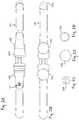
- FIG. 1Ais an elevation view of an outer side of a back brace according to an embodiment of the present invention.
- FIG. 1Bis an elevation view of an inner side of the back brace of FIG. 1A .
- FIG. 1Cis an elevation view of a partially disassembled back panel of the back brace of FIG. 1A .
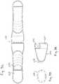
- FIG. 2Ais an elevation view of an outer side of a back brace according to another embodiment of the present invention.
- FIG. 2Bis an elevation view of an inner side of the back brace of FIG. 2A .
- FIG. 2Cis an elevation view of a support insert for use with the back brace of FIG. 2A .
- FIG. 2Dis an elevation view of a lateral support for use with the back brace of FIG. 2A .
- FIG. 2Eis an elevation view of a support insert for use with the lateral support of FIG. 2D .
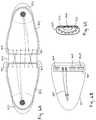
- FIG. 3Ais an elevation view of an outer side of a back brace according to another embodiment of the present invention.
- FIG. 3Bis an elevation view of an inner side of the back brace of FIG. 3A .
- FIG. 3Cis an alternate elevation view of an inner side of the back brace of FIG. 3A .
- FIG. 3Dis an elevation view of an anterior support insert for use with the back brace of FIG. 3A .
- FIG. 3Eis an elevation view of a partially disassembled back panel of the back brace of FIG. 3A .
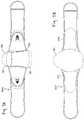
- FIG. 4Ais an elevation view of an outer side of a back brace according to another embodiment of the present invention.
- FIG. 4Bis an elevation view of an inner side of the back brace of FIG. 4A .
- FIG. 4Cis an alternate elevation view of an inner side of the back brace of FIG. 4A .
- FIG. 4Dis an elevation view of a posterior support insert for use with the back brace of FIG. 4A .
- FIG. 4Eis an elevation view of a partially disassembled posterior pad for use with the back brace of FIG. 4A .
- FIG. 5Ais an elevation view of an outer side of a back brace according to another embodiment of the present invention.
- FIG. 5Bis an elevation view of an inner side of the back brace of FIG. 5A .
- FIG. 5Cis an elevation view of an anterior support insert for use with the back brace of FIG. 5C .
- FIG. 5Dis an elevation view of a lateral support for use with the back brace of FIG. 5A .
- FIG. 6Ais an elevation view of an outer side of back panels having an alternate closure system arrangement.
- FIG. 6Bis a detailed elevation view of a portion of the closure system of the embodiment depicted in FIG. 6A .
- FIG. 6Cis a detailed elevation view of a lace guide according to the embodiment of FIG. 6A .
- FIG. 7Ais an elevation view of an outer side of a back brace according to an alternate embodiment of the present invention.
- FIG. 7Bis an elevation view of an inner side of the back brace of FIG. 7A .
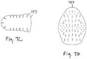
- FIG. 7Cis an elevation view of a lateral support insert for use with the back brace of FIG. 7A .
- FIG. 7Dis an elevation view of a posterior support insert for use with the back brace of FIG. 7A .
- FIG. 8Ais an elevation view of an outer side of a back brace according to another embodiment of the present invention.
- FIG. 8Bis an elevation view of an inner side of the back brace of FIG. 8A .
- FIG. 8Cis an elevation view of a lateral support insert for use with the back brace of FIG. 8A .
- FIG. 8Dis an elevation view of an attachment mechanism for use with a posterior pad of the back brace of FIG. 8A .
- FIG. 8Eis an elevation view of a posterior support insert for use with the back brace of FIG. 8A .
- FIG. 8Fis an elevation view of an anterior support insert for use with the back brace of FIG. 8A .
- FIG. 9Ais an exploded elevation view of an outer side of a back brace according to another embodiment of the present invention.
- FIG. 9Bis an exploded elevation view of an inner side of the back brace of FIG. 9A .
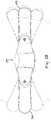
- FIG. 10is an elevation view of an outer side of a back brace according to an embodiment of the present invention, depicting the range of attachment angles of the front panels to the back panels.
- Embodiments of the present inventiongenerally include first and second back panels adjustably coupled via a closure system, and first and second front panels releasably attachable to one other via attachment means.
- Back brace 100is depicted, which is configured for use as a sacroiliac belt.
- Back brace 100includes a first back panel 102 , a second back panel 104 , a first front panel 106 , a second front panel 108 , and a closure system 110 .
- Each of back panels 102 and 104includes a dorsal end 120 , a lateral (side) end 122 , an outer face 124 and an inner face 126 .
- Back panels 102 and 104are configured such that the dorsal ends 120 of each back panel are proximate one another and capable of being positioned on the lower back of a wearer, with the back panels 102 , 104 capable of wrapping around the wearer such that the lateral ends 122 of each panel 102 , 104 are generally positioned on the side of the wearer.
- Dorsal end 120 of each back panel 102 , 104may include a support 132 . As depicted in FIG. 1C , support 132 is secured within the structure of back panels 102 , 104 such as by sewing or gluing. In another embodiment, back panels 102 , 104 may be provided with a pocket such that support 132 may be removable.
- each of back panels 102 , 104 and front panels 106 , 108are constructed of multiple layers of material.
- the outer face/layercomprises unbroken-loop (“UBL”) fabric
- a middle layercomprises closed-cell foam
- the inner face/layercomprises tricot nylon.
- one or more of the layersmay be constructed of a stretchable material.
- none of the layersare of a stretchable material. Additional layers of material may also be added as desired, such as spacer fabric, reinforcing material, waterproofing material, and/or additional foam layers for padding.
- the outer, middle and inner layersmay be joined at their edges, such as by sewing, gluing, thermal or chemical bonding, or other suitable methods.
- Durable binding fabric 128such as grosgrain, is sewn around the edge of the panels to provide additional strength. Stitching 129 is utilized generally in construction of many portions of brace 100 , as is apparent from the Figures.
- support 132is constructed from a thermoformable polymer material as described in commonly assigned. Provisional Patent Application No. 61/677,779, filed Jul. 31, 2012 and titled “Foam Core Sandwich Splint” or in commonly assigned U.S. Published Patent Application No. 2012/0101417 to Joseph, the disclosures of which are hereby incorporated by reference in their entireties.
- the thermoformable materialis heat formable within a target temperature range, and rigid or generally rigid below a minimum temperature.
- the target temperature rangemay comprise between 140 and 250 degrees Fahrenheit, between 160 and 220 degrees Fahrenheit, or between 160 and 200 degrees Fahrenheit.
- support 132may comprise polyvinyl chloride (“PVC”) sheet or foam, amorphous polyethylene terephthalate (“APET”), recycled polyethylene terephthalate (“RPET”), polycaprolactone, caprolactone, low density polyethylene (“LDPE”), high density polyethylene (“HDPE”), or other materials known to one of ordinary skill in the art.
- PVCpolyvinyl chloride
- APETamorphous polyethylene terephthalate
- RPETrecycled polyethylene terephthalate
- polycaprolactonepolycaprolactone
- caprolactonecaprolactone
- LDPElow density polyethylene
- HDPEhigh density polyethylene
- support 132may be preformed to a desired shape before application of the back brace to a wearer.
- Support 132may include multiple layers of material, for example one or more layers of foam or fabric may be included in addition to a thermoformable material layer.
- Support 132may also include two or more layers of thermoformable material, which may be thermoformable at similar temperatures, or which may be thermoformable at different temperatures.
- support 132may comprise a first layer of HDPE which is thermoformable at a relatively high temperature in the range of 300 to 400 degrees Fahrenheit and has a thickness of 0.05-1.0 mm, and a second layer of thermoformable material as described in the applications incorporated by reference above and having a thickness of 1.0-1.5 mm.
- the supportmay be heated to within a range to thermoform the first HDPE layer, and formed to a desired general shape. After allowing the support to cool to room temperature, the support may then be heated to a temperature within the range to thermoform the second thermoformable layer only, the support can then be formed to a more specific desired shape. Provided the second thermoformable layer is stronger than the first HDPE layer, the support will take the specific desired shape.
- the shape of support 132may be reset by heating support 132 to within the range of thermoformability of the HDPE layer.
- Each of front panels 106 , 108includes a lateral (side) end 140 , a ventral end 142 , an outer face 144 and an inner face 146 .
- Front panels 106 , 108are configured so that the lateral end 140 is releasably coupleable to the lateral end 122 of back panels 102 , 104 , such that front panels 102 , 104 will extend generally from the side of a wearer around the front of a wearer with ventral ends 142 of each front panel 106 , 108 being releasably coupleable to one another.
- a plurality of grip strips 150are provided on inner face 146 of front panels 106 , 108 , to prevent shifting of back brace 100 on a wearer, as depicted in FIG. 1B .
- Grip strips 150may comprise silicone, rubber, or other suitable materials known to one skilled in the art. Strips 150 may be arranged in other shapes or configurations than those depicted.
- the ventral end 142 of one or both front panels 106 , 108may be provided with a mitten pocket 154 on outer face 144 .
- Pocket 154is sized and shaped to receive a portion or all of a wearer's hand, so as to provide an aid when donning the back brace.
- attachment means 156 in the form of hook-and-loop-compatible materialmay be provided on ventral end 142 of one or both front panels 106 , 108 on outer face 144 and inner face 146 to facilitate attachment of front panel 106 overlapping front panel 108 , or vice versa.
- at least a portion of inner face 146 of each panel 106 , 108may include hook material on ventral end 142 to interface with the UBL fabric comprising outer face 144 of panels 106 , 108 .
- each of back panels 102 , 104include attachment means 134 on the inner face 126 of lateral end 122 .
- Attachment means 134are configured to releasably couple back panels 102 , 104 to front panels 106 , 108 via attachment means 152 on outer face 144 of side panels 106 , 108 .
- Attachment means 134may comprise any fasteners suitable for use on an orthopedic brace, including but not limited to snaps, buttons, hook-and-loop material, or other suitable fasteners as would be apparent to one skilled in the art.
- attachment means 134comprises hook material, which can interface with the UBL fabric comprising attachment means 152 on outer face 144 of front panels 106 , 108 .
- a tether or other supplemental restraintmay be provided as part of attachment means 134 , so as to prevent complete separation of back panels 102 , 104 from front panels 106 , 108 while still allowing front panels 106 , 108 to be repositioned as desired.
- closure system 110generally comprises a reel 160 secured to outer face 124 of back panel 102 or 104 , and one or more laces 162 coupled to reel 160 .
- Lace 162is fed beneath outer face 124 and into guide tubes 164 (not shown), emerging at the edge of dorsal end 120 through eyelets 165 before being wound through guides 166 .
- guides 166are positioned on outer face 124 , but in another embodiment guides 166 may be located within the structure of back panels 102 , 104 .
- Guides 166may comprise loops of sturdy material, such as nylon webbing.
- webbing guides 166are provided with an internal guide having a generally arcuate profile, to reduce the friction on lace 162 .
- closure system 110may be configured to provide a mechanical advantage.
- reel 160may be sized and configured to provide a mechanical advantage of about 2:1, or of about 3:1, or of about 4:1, wherein the advantage is determined by the ratio of the circumference of the reel to the circumference of the spool (not pictured) around which lace 162 is wound.
- Each of guides 166may be sized and positioned to provide a mechanical advantage of about 2:1, or of about 3:1, or of about 4:1.
- closure system 110includes a reel having a mechanical advantage of 2:1, and three guides 166 each having a mechanical advantage of 2:1, for an overall closure system mechanical advantage of 18:1. Other arrangements are within the scope of the present invention.
- Reel 160is configured to mechanically tighten lace 162 and lock it in place, yet be quickly and easily released.
- Reel 160may be of the type available from Boa Technology, which allows laces 162 to be drawn into reel 160 by rotating reel 160 and thereby tightening the fit of brace 100 , and also allows tension on laces 162 to be released by pulling on reel 160 .
- the area proximate the attachment point of reel 160may be strengthened or otherwise reinforced to prevent buckling or distortion of back brace 100 when tightening reel 160 . Additional information on reels, laces, lace guides and closure systems in general that are suitable for use with the present invention may be found in U.S. Pat. Nos.
- the '348 patentutilizes a pull tab on each side of the brace, which in order to tighten require a patient to reach around their side to grasp the tab, pull the tab outward from their body with enough force so as to create sufficient compression on the lower back region to treat the condition for which the brace was prescribed, and then secure the tab to the body of the brace. This procedure is then repeated for the second pull tab, and the overall procedure that may be difficult for many patients experiencing lower back pain and/or injury.
- Back brace 301includes an alternate closure system 111 , an anterior insert 159 , and a plurality of lateral panels 192 .
- Closure system 111is similar in many respects to closure system 110 of FIGS. 1A-1C , but features a plurality of internal lace guides affixed to an internal layer of brace 101 , with a plurality of eyelets 165 on the outer face 124 of panels 102 , 104 .
- Closure system 111is of the type depicted in FIGS. 6A-6C , described in further detail below.
- Anterior insert 159is configured to be positioned within ventral end 142 of either front panel 106 , 108 , such as within a pocket provided for such purpose, or such as by sewing during construction of back brace 101 , so that when brace 101 is fitted to a wearer, insert 159 is positioned generally on the anterior of the wearer.
- Each of lateral panels 192includes a support 193 , which, as with insert 159 , may be constructed from a thermoformable polymer material, or PVC sheet or foam, APET, RPET, polycaprolactone, caprolactone, LDPE. HDPE, or other materials known to one of ordinary skill in the art.
- Lateral panels 192may be constructed from one or materials previously described herein, such as non-stretchable UBL fabric. Lateral panels 192 may attach to back brace 101 via hook-and-loop fastening means, or other suitable means known to those skilled in the art, and may be secured to back panels 102 , 104 at any desired position.
- Back brace 200is depicted, which is configured for use as a spine brace.
- Back brace 200is similar in many respects to back brace 100 , and generally includes a first back panel 202 , a second back panel 204 , a first front panel 206 , a second front panel 208 , and a closure system 210 .
- Each of back panels 202 and 204includes a dorsal end 220 , a lateral end 222 , an outer face 224 and an inner face 226 .
- Back panels 202 and 204are configured such that the dorsal ends 220 of each back panel are proximate one another and capable of being positioned on the lower back of a wearer, with the back panels 202 , 204 capable of wrapping around the wearer such that the lateral ends 222 of each panel 202 , 204 are generally positioned on the side of the wearer.
- Dorsal end 220 of each panel 202 , 204may include a support 232 .
- support 232is secured within the structure of back panels 202 , 204 such as by sewing or gluing.
- back panels 202 , 204may be provided with a pocket such that support 232 may be removable.
- each of back panels 202 , 204 and front panels 206 , 208are constructed of multiple layers of material.
- the outer face/layercomprises unbroken-loop (“UBL”) fabric
- a middle layercomprises closed-cell foam
- the inner face/layercomprises tricot nylon.
- one or more of the layersmay be constructed of a stretchable material.
- none of the layersare of a stretchable material. Additional layers of material may also be added as desired.
- the outer, middle and inner layersmay be joined at their edges, such as by sewing, gluing, thermal or chemical bonding, or other suitable methods.
- Durable binding fabricsuch as grosgrain may be sewn around the edge of the panels to provide additional strength.
- Support 232may be of a similar construction to support 132 described earlier, and may therefore be constructed from a thermoformable polymer material, or PVC sheet or foam, APET, RPET, polycaprolactone, caprolactone, LDPE, HDPE, or other materials known to one of ordinary skill in the art. In one embodiment, support 232 may be preformed to a desired shape before application of the hack brace to a wearer.
- Each of front panels 206 , 208includes a lateral end 240 , a ventral end 242 , an outer face 244 and an inner face 246 .
- Front panels 206 , 208are configured so that the lateral end 240 is releasably coupleable to the lateral end 222 of back panels 202 , 204 , such that front panels 202 , 204 will extend generally from the side of a wearer around the front of a wearer with ventral ends 242 of each front panel 206 , 208 being releasably coupleable to one another.
- Brace 200may also be provided with one or more sizing indicators 253 , as depicted in FIGS. 3A-3E .
- Sizing indicators 253may comprise stitch lines on outer face 244 and/or inner face 246 of front panels 206 , 208 , as depicted in FIGS. 3A-3E , or apertures in panels 206 , 208 , or other means of sizing indicators as will be apparent to those skilled in the art. Other locations and arrangements of sizing indicators 253 are within the scope of the invention.
- the ventral end 242 of one or both front panels 206 , 208may be provided with a mitten pocket 254 on outer face 244 .
- Pocket 254is sized and shaped to receive a portion or all of a wearer's hand, so as to provide an aid when donning the back brace.
- attachment means 256 in the form of hook-and-loop-compatible materialmay be provided on ventral end 242 of one or both front panels 206 , 208 on outer face 244 and inner face 246 to facilitate attachment of front panel 206 overlapping front panel 208 , or vice versa.
- inner face 246 of each panel 206 , 208may include hook material on ventral end 242 to interface with the UBL fabric comprising outer face 244 of panels 206 , 208 .
- ventral end 242 of one or both front panels 206 , 208may be provided with a pocket 258 on either outer face 244 or inner face 246 , configured to receive an anterior insert 259 , such as depicted in FIGS. 3B-3D .
- Insert 259may be constructed from a thermoformable polymer material, or PVC sheet or foam, APET, RPET, polycaprolactone, caprolactone, LDPE, HDPE, or other materials known to one of ordinary skill in the art.
- FIG. 3Cdepicts insert 259 partially withdrawn from pocket 258 , for the purpose of illustration. Pocket 258 and insert 259 are configured and arranged such that when brace 200 is fitted to a wearer, insert 259 is positioned generally on the anterior of the wearer.
- each of back panels 202 , 204include attachment means 234 on the inner face 226 of lateral end 222 .
- Attachment means 234are configured to releasably couple back panels 202 , 204 to front panels 206 , 208 via attachment means 252 on outer face 244 of side panels 206 , 208 .
- Attachment means 234may comprise any fasteners suitable for use on an orthopedic brace, including but not limited to snaps, buttons, hook-and-loop material, or other suitable fasteners as would be apparent to one skilled in the art.
- attachment means 234comprises hook material, which can interface with the UBL fabric comprising outer face 244 of front panels 206 , 208 .
- a tether or other supplemental restraintmay be provided as part of attachment means 234 , so as to prevent complete separation of back panels 202 , 204 from front panels 206 , 208 while still allowing front panels 206 , 208 to be repositioned as desired.
- closure system 210generally comprises a reel 260 secured to outer face 224 of back panel 202 or 204 , and one or more laces 262 coupled to reel 260 .
- Lace 262is fed beneath outer face 224 and into guide tubes 264 (not shown), emerging at the edge of dorsal end 220 through eyelets 265 before being wound through guides 266 .
- guides 266are positioned on outer face 224 , but in another embodiment guides 266 may be located within the structure of back panels 202 , 204 .
- Reel 260is configured to mechanically tighten lace 262 and lock it in place, yet be quickly and easily released.
- Reel 260may be of the type available from Boa Technology, and generally functions as previously described herein.
- the area proximate the attachment point of reel 260may be strengthened or otherwise reinforced to prevent buckling or distortion of back brace 200 when tightening reel 260 .
- Closure system 210may be sized and configured to provide a mechanical advantage, as described above with respect to closure system 110 .
- Back brace 300is depicted, which is configured for use as a spine brace.
- Back brace 300is similar in many respects to earlier-described back brace embodiments, and generally includes a first back panel 302 , a second back panel 304 , a first front panel 306 , a second front panel 308 , and a closure system 310 .
- Each of back panels 302 and 304includes a dorsal end 320 , a lateral end 322 , an outer face 324 and an inner face 326 .
- Back panels 302 and 304are configured such that the dorsal ends 320 of each back panel are proximate one another and capable of being positioned on the lower back of a wearer, with the back panels 302 , 304 capable of wrapping around the wearer such that the lateral ends 322 of each panel 302 , 304 are generally positioned on the side of the wearer.
- Dorsal end 320 of each panel 302 , 304may include a support 332 .
- support 332is secured within the structure of back panels 302 , 304 such as by sewing or gluing.
- back panels 302 , 304include a pocket 330 such that support 332 may be removable.
- each of back panels 302 , 304 and front panels 306 , 308are constructed of multiple layers of material.
- the outer face/layercomprises unbroken-loop (“UBL”) fabric
- a middle layercomprises closed-cell foam
- the inner face/layercomprises tricot nylon.
- one or more of the layersmay be constructed of a stretchable material.
- none of the layersare of a stretchable material.
- the outer, middle and inner layersmay be joined at their edges, such as by sewing, gluing, thermal or chemical bonding, or other suitable methods.
- Durable binding fabricsuch as grosgrain may be sewn around the edge of the panels to provide additional strength.
- Support 332may be of a similar construction to support 132 described earlier, and may therefore be constructed from a thermoformable polymer material, or PVC sheet or foam, APET, RPET, polycaprolactone, caprolactone, LDPE, HDPE, or other materials known to one of ordinary skill in the art. In one embodiment, support 332 may be preformed to a desired shape before application of the back brace to a wearer.
- Each of front panels 306 , 308includes a lateral end 340 , a ventral end 342 , an outer face 344 and an inner face 346 .
- Front panels 306 , 308are configured so that the lateral end 340 is releasably coupleable to the lateral end 322 of back panels 302 , 304 , such that front panels 302 , 304 will extend generally from the side of a wearer around the front of a wearer with ventral ends 342 of each front panel 306 , 308 being releasably coupleable to one another.
- Brace 300may also be provided with one or more sizing indicators 353 , as depicted in FIG. 4A .
- Sizing indicators 353comprise stitch lines on inner face 346 of front panels 306 , 308 , although other locations and arrangements of sizing indicators 353 are within the scope of the invention.
- the ventral end 342 of one or both front panels 306 , 308may be provided with a mitten pocket 354 on outer face 344 .
- Pocket 354is sized and shaped to receive a portion or all of a wearer's hand, so as to provide an aid when donning the back brace.
- attachment means 356 in the form of hook-and-loop-compatible materialmay be provided on ventral end 342 of one or both front panels 306 , 308 on outer face 344 and inner face 346 to facilitate attachment of front panel 306 overlapping front panel 308 , or vice versa.
- inner face 346 of each panel 306 , 308may include hook material on ventral end 342 to interface with the UBL fabric comprising outer face 344 of panels 306 , 308 .
- ventral end 342 of one or both front panels 306 , 308may be provided with a pocket 358 on either outer face 344 or inner face 346 , configured to receive an anterior insert 359 , such as depicted in FIGS. 4A-4C .
- Insert 359may be constructed from a thermoformable polymer material, or PVC sheet or foam, APET, RPET, polycaprolactone, caprolactone. LDPE, HDPE, or other materials known to one of ordinary skill in the art.
- Pocket 358 and insert 359are configured and arranged such that when brace 300 is fitted to a wearer, insert 359 is positioned generally on the anterior of the wearer.
- each of back panels 302 , 304include attachment means 334 on the inner face 326 of lateral end 322 .
- Attachment means 334are configured to releasably couple back panels 302 , 304 to front panels 306 , 308 via attachment means 352 on outer face 344 of side panels 306 , 308 .
- Attachment means 334may comprise any fasteners suitable for use on an orthopedic brace, including but not limited to snaps, buttons, hook-and-loop material, or other suitable fasteners as would be apparent to one skilled in the art.
- attachment means 334comprises hook material, which can interface with the UBL fabric comprising outer face 344 of front panels 306 , 308 .
- a tether or other supplemental restraintmay be provided as part of attachment means 334 , so as to prevent complete separation of back panels 302 , 304 from front panels 306 , 308 while still allowing front panels 306 , 308 to be repositioned as desired.
- closure system 310generally comprises a first reel 360 secured to outer face 324 of back panel 302 or 304 , a second reel 361 secured to outer face 324 of the other back panel 302 or 304 , and a plurality of laces 362 , 363 coupled to reels 360 , 361 , respectively.
- Laces 362 , 363are fed beneath outer face 324 and into guide tubes 364 , emerging at the edge of dorsal end 320 through eyelets 365 before being wound through guides 366 .
- Guides 366are positioned on outer face 324 , but in another embodiment guides 366 may be located within the structure of back panels 302 , 304 .
- Reels 360 , 361are configured to mechanically tighten their respective laces and lock them in place, yet be quickly and easily released.
- Closure system 310may be sized and configured to provide a mechanical advantage, as described above with respect to other closure system embodiments.
- Reels 360 , 361are preferably of the type available from Boa Technology, and generally function as previously described herein.
- lace 362is configured to tighten a superior (upper) portion of the brace via reel 360
- lace 363is configured to tighten an inferior (lower) portion of the brace via reel 361
- Reel 360 and lace 362are operable independently of reel 361 and lace 363 , allowing variance in the tension of the superior portion of the back brace and the inferior portion of the back brace.
- the area proximate the attachment point of reels 360 , 361may be strengthened or otherwise reinforced to prevent buckling or distortion of back brace 300 when tightening reel 360 and/or reel 361 .
- Brace 300may include an optional posterior pad 380 to provide additional comfort and/or support to a wearer.
- Posterior pad 380may be of a similar construction as is used for panels 302 , 304 , 306 or 308 discussed above.
- pad 380includes a support 382 , which may be of a similar construction to support 132 described earlier, and may therefore be constructed from one or more layers of thermoformable polymer material, or PVC sheet or foam, APET, RPET, polycaprolactone, caprolactone, LDPE, HDPE, or other materials known to one of ordinary skill in the art.
- Support 382may be integrated into pad 380 , or may be removably coupled to pad 380 , such as by book and loop connection or fitting into a pocket on pad 380 (not shown).
- Posterior pad 380may simply be fitted over back brace 300 , without being directly attached to back brace 300 .
- pad 380is capable of moving independently of brace 300 , for example allowing pad 380 to remain centered over the spine of a patient while brace 300 is being tightened, or allowing pad 380 to slide side-to-side with respect to brace 300 as desired.
- posterior pad 380includes a first closure flap 386 and a second closure flap 387 which are configured to retain posterior pad 380 on back brace 300 , while still allowing posterior pad 380 to be adjusted and/or moved as desired by the patient.
- Closure flap 386may be provided with one portion of a hook-and-loop material, while closure flap 387 is provided with the other portion, although alternate means of coupling flaps 386 , 387 are within the scope of the present invention.
- Posterior pad 380may also include a smooth surface configured to be in contact with laces 362 upon installation of pad 380 on back brace 300 , in order to reduce friction on laces 362 while donning and/or adjusting the fit of back brace 300 . Such surface may be included as a separate layer of material in posterior pad 380 , or may support 382 itself.
- posterior pad 380may be provided with an attachment means configured to releasably couple posterior pad 380 to back brace 300 .
- inner face 326 of back panels 302 , 304may comprise UBL fabric while posterior pad 380 is provided with sections of hook material so as to provide a hook-and-loop connection between posterior pad 380 and back brace 300 .
- back brace 300includes a plurality of sections of loop material 351 attached to back panels 302 , 304 , such as by sewing or gluing. Posterior pad 380 may then be provided with sections of hook material so as to provide a hook-and-loop connection between posterior pad 380 and back brace 300 .
- a further embodiment of a posterior pad featuring an attachment meansis described below in reference to FIGS. 8A-8F .
- Brace 301is similar to back brace 300 except as depicted in the Figs., and as described herein.
- Back brace 301features an alternate closure system 311 which is similar in many respects to closure system 310 of FIGS. 4A-4E , but differs with a plurality of internal lace guides affixed to an internal layer of brace 301 , with a plurality of eyelets 365 on the outer face 324 of panels 302 , 304 .
- Closure system 311is of the type depicted in FIGS. 6A-6C and described in further detail below.
- Brace 301also includes a pocket 330 in dorsal end 320 of panel 302 and/or panel 304 to receive support 332 .
- An anterior pad 355is also provided, being configured to be releasably coupled directly to inner face 346 , or a separate attachment feature 357 may be provided, as depicted in FIG. 5B .
- anterior pad 355may include a layer of UBL fabric, and a component (not pictured) having hook material on both sides may be provided to releasably couple anterior pad 355 to the UBL fabric of inner face 346 .
- Brace 301also features alternate sizing indicators 353 , in the form of holes provided in front panels 306 , 308 .
- FIGS. 6A-6Can alternate closure system 311 is depicted, having a plurality of internal lace guides 368 .
- FIG. 6Bdepicts middle layer 327 of back panel 302 , lacing guide tubes 364 , and lace guides 368 secured to reinforcement 328 .
- Each of lace guides 368generally includes a base portion 369 and a channel 370 through which lace 362 or 363 passes.
- Channel 370presents a smooth path of travel for lace 362 , in the form of a generally arcuate profile.
- This closure systemcould be used in place of any other closure systems described herein, with either single or dual reels.
- Brace 302is similar in many respects to back braces 300 and 301 , except as depicted in the Figs., and as described herein.
- Back brace 302features a tall posterior pad 381 and a plurality of lateral panels 392 , such that the brace is configured as a chairback brace.
- Posterior pad 381includes an internal support 383 , and is generally similar in construction and function to posterior pad 380 .
- Lateral panels 392each include a support 393 within them. Support 393 , depicted in FIG.
- Lateral panels 392may be constructed from materials previously described herein, such as non-stretchable UBL fabric. Lateral panels 392 may attach to back brace 302 via hook-and-loop fastening means, or other suitable means known to those skilled in the art, and may be attachable to one or more of back panels 302 , 304 , front panels 306 , 308 , and/or either side of posterior pad 381 at any desired position.
- Brace 303is similar to back braces 300 , 301 and 302 , except as depicted in the Figs., and as described herein.
- Back brace 303features alternate embodiments of posterior pad 381 and lateral panels 392 .
- Posterior pad 381is generally similar in construction and function to earlier-described embodiments of posterior pads, and includes an internal support 383 and is depicted in FIGS. 8A, 8E without an outer cover over support 383 .
- Brace 303includes a closure system of the type depicted in FIGS. 6A-6C .
- An anterior pad 355is also provided, being configured to be releasably coupled directly to inner face 346 , or a separate attachment feature 357 may be provided, as depicted in FIG. 8B .
- Brace 303features alternate sizing indicators 353 , in the form of holes provided in front panels 306 , 308 .
- Brace 303further includes alternate embodiments of lateral panels 392 with inserts 393 .
- Lateral panels 392may be attachable to posterior pad 381 , back panels 202 , 204 , and/or front panels 306 , 308 at any desired position.
- a glide plate 395is provided to releasably couple posterior pad 381 to brace 303 .
- Glide plate 395functions as a slider attachment mechanism, and is coupleable to an outer surface of posterior pad 381 at a desired position, and generally includes a pair of attachment means in the form of rivets 396 movably retained within tracks 397 . Rivets 396 are of a double-cap type. Other moveable attachment means are within the scope of the invention and will be apparent to one of skill in the art.
- each panel 302 , 304may be configured to include a buttonhole so as to receive rivets 396 .
- posterior pad 381 having glide plate 395is generally aligned with brace 303 , and rivets 396 are passed through corresponding buttonholes in panels 302 , 304 .
- the sizing of glide plate 395 and tracks 397is selected to allow posterior pad 381 to remain properly centered over a wearer's spine during donning and wearing.
- Back brace 304is similar in most respects to back brace 303 , but features alternately profiled anterior pad 355 , posterior pad 383 , and lateral panels 392 .
- inventions of the present inventionprovide a customizable fit to a wide range of patients of different body types.
- a method of fitting and adjusting a back brace according to the present inventionwill now be described in reference to back brace 300 by way of example, although much of the method is applicable to the other embodiments described herein.
- the order of the steps described belowshould not be considered limiting, as some steps may be performed in alternate sequences, may be omitted, or may be performed more than once.
- Back brace 300is first extended into a fully open position if necessary, by loosening closure system 310 . This may be accomplished by releasing reels 360 , 361 , such as by pulling outward on a knob portion of the reel. Back panels 302 , 304 can then be pulled away from one another. Brace 300 can then be applied to the wearer, generally centering laces 362 , 363 over the spine of the wearer. Front panels 306 , 308 are then loosely wrapped around the waist of the patient, such that ventral ends 342 of one of front panels 306 , 308 sufficiently overlaps the other at the wearer's ventral midline.
- Mitten pocket 354may be utilized if desired, to provide additional leverage when wrapping the front panels around the wearer.
- a sufficient overlapmay be within the range of four to eight inches, although this should not be considered limiting.
- Reels 360 , 361may then be actuated to tighten laces 362 , 363 , respectively, drawing back panels 302 , 304 toward each other and tightening brace 300 around the wearer.
- front panels 306 , 308can be adjusted with respect to back panels 302 , 304 , via the interface between attachment means 334 on back panels 302 , 304 and attachment means 352 on front panels 306 , 308 .
- One or more of front panels 306 , 308are separated from back panels 302 , 304 , then repositioned as desired to increase or decrease the circumferential size of (or length of) brace 300 , then reattached via the attachment means 334 and 352 .
- the angle of back panels 302 , 304may be adjusted with respect to one another with the use of reels 360 , 361 , in order to allow a better fit on certain body types or align the brace to account for any injuries present on the wearer.
- reel 360may be tightened more than reel 361 in order to draw the tops of back panels 302 , 304 closer to one another compared to the bottom of back panels 302 , 304 , to provide a good fit of brace 300 around the hips of the wearer.
- front panels 306 , 308may also be adjusted if desired to allow a better fit on certain body types or align the brace to account for any injuries present on the wearer.
- front panels 306 , 308may be attached to back panels 302 , 304 via attachment means 334 and 352 at any desired angle.
- brace 300includes any thermoformable components, such as supports and/or inserts as described herein, the components should be heated as part of the fitting process. Suitable methods of heating include those described in U.S. Published Patent Application No. 2012/0101417 to Joseph, previously incorporated by reference.
- the thermoformable componentsmay be removed from brace 300 to be heated separately, or the thermoformable panels may be heated while on the patient with the use of a heat source such as a heat gun, temporarily attached exothermic pack, or other suitable means.
- back brace 300Use of the described adjustment features of back brace 300 will provide a more uniform, consistent fit on the wearer, preventing brace 300 from becoming misadjusted due to walking, sitting/standing, and other normal movements of the wearer.
- brace 300may be removed in order to trim excess material if necessary from front panels 306 , 308 along sizing indicators 353 . If desired, various accessories such as insert 359 , posterior pads 380 or 381 , and/or lateral panels 392 may be attached to brace 300 at a desired position.
- the present inventioncomprises a kit including a back brace according to one or more of the embodiments described herein, and a set of instructions recorded on a tangible medium for fitting the back brace to a wearer according to the methods described herein.
- the instructionsmay comprise instructions for use (IFU) or directions for use, according to the requirements of one or more regulatory bodies and/or government agencies.
- the instructionsmay be intended for a patient, or for a health care professional.
- the kitmay include indications which link a user to electronically accessible instructions.
Landscapes
- Health & Medical Sciences (AREA)
- Nursing (AREA)
- Orthopedic Medicine & Surgery (AREA)
- Engineering & Computer Science (AREA)
- Biomedical Technology (AREA)
- Heart & Thoracic Surgery (AREA)
- Vascular Medicine (AREA)
- Life Sciences & Earth Sciences (AREA)
- Animal Behavior & Ethology (AREA)
- General Health & Medical Sciences (AREA)
- Public Health (AREA)
- Veterinary Medicine (AREA)
- Orthopedics, Nursing, And Contraception (AREA)
- Professional, Industrial, Or Sporting Protective Garments (AREA)
Abstract
Description
Claims (20)
Priority Applications (2)
| Application Number | Priority Date | Filing Date | Title |
|---|---|---|---|
| US15/599,233US10517749B2 (en) | 2012-11-12 | 2017-05-18 | Orthopedic back brace |
| US16/723,005US11484429B2 (en) | 2012-11-12 | 2019-12-20 | Orthopedic back brace |
Applications Claiming Priority (2)
| Application Number | Priority Date | Filing Date | Title |
|---|---|---|---|
| US13/674,613US9655761B2 (en) | 2012-11-12 | 2012-11-12 | Orthopedic back brace |
| US15/599,233US10517749B2 (en) | 2012-11-12 | 2017-05-18 | Orthopedic back brace |
Related Parent Applications (1)
| Application Number | Title | Priority Date | Filing Date |
|---|---|---|---|
| US13/674,613ContinuationUS9655761B2 (en) | 2012-11-12 | 2012-11-12 | Orthopedic back brace |
Related Child Applications (1)
| Application Number | Title | Priority Date | Filing Date |
|---|---|---|---|
| US16/723,005ContinuationUS11484429B2 (en) | 2012-11-12 | 2019-12-20 | Orthopedic back brace |
Publications (2)
| Publication Number | Publication Date |
|---|---|
| US20170348134A1 US20170348134A1 (en) | 2017-12-07 |
| US10517749B2true US10517749B2 (en) | 2019-12-31 |
Family
ID=50682379
Family Applications (3)
| Application Number | Title | Priority Date | Filing Date |
|---|---|---|---|
| US13/674,613Active2033-05-26US9655761B2 (en) | 2012-11-12 | 2012-11-12 | Orthopedic back brace |
| US15/599,233Active2033-11-03US10517749B2 (en) | 2012-11-12 | 2017-05-18 | Orthopedic back brace |
| US16/723,005Active2034-01-04US11484429B2 (en) | 2012-11-12 | 2019-12-20 | Orthopedic back brace |
Family Applications Before (1)
| Application Number | Title | Priority Date | Filing Date |
|---|---|---|---|
| US13/674,613Active2033-05-26US9655761B2 (en) | 2012-11-12 | 2012-11-12 | Orthopedic back brace |
Family Applications After (1)
| Application Number | Title | Priority Date | Filing Date |
|---|---|---|---|
| US16/723,005Active2034-01-04US11484429B2 (en) | 2012-11-12 | 2019-12-20 | Orthopedic back brace |
Country Status (5)
| Country | Link |
|---|---|
| US (3) | US9655761B2 (en) |
| EP (1) | EP2916673B1 (en) |
| CN (2) | CN109893318B (en) |
| ES (1) | ES2696699T3 (en) |
| WO (1) | WO2014074855A1 (en) |
Cited By (3)
| Publication number | Priority date | Publication date | Assignee | Title |
|---|---|---|---|---|
| US10940031B2 (en) | 2009-02-24 | 2021-03-09 | Djo, Llc | Composite material for custom fitted products |
| US11191627B2 (en) | 2012-08-01 | 2021-12-07 | Djo, Llc | Orthopedic brace for animals |
| US11484429B2 (en) | 2012-11-12 | 2022-11-01 | Djo, Llc | Orthopedic back brace |
Families Citing this family (41)
| Publication number | Priority date | Publication date | Assignee | Title |
|---|---|---|---|---|
| US8303527B2 (en) | 2007-06-20 | 2012-11-06 | Exos Corporation | Orthopedic system for immobilizing and supporting body parts |
| US9295748B2 (en) | 2012-07-31 | 2016-03-29 | Exos Llc | Foam core sandwich splint |
| EP2897559B1 (en) | 2012-09-19 | 2019-03-06 | Ossur HF | Panel attachment and circumference adjustment systems for an orthopedic device |
| EP2938299B1 (en)* | 2012-12-27 | 2019-06-19 | Deroyal Industries, Inc. | Adjustable circumferential length lumbar sacral brace |
| US9795500B2 (en)* | 2013-01-24 | 2017-10-24 | Ossur Hf | Orthopedic device for treating complications of the hip |
| US10555863B2 (en)* | 2013-03-15 | 2020-02-11 | Jacob Randy Hall | Cryotherapy compression system |
| US20140316493A1 (en)* | 2013-04-18 | 2014-10-23 | Bryan E. Kilbey | Lumbar Cryotherapy Belt with Access Window |
| CN105611968B (en)* | 2013-08-08 | 2019-08-16 | Qfix 系统有限责任公司 | Thermoformable formula patient locating pad, system and patient's locating pad production method |
| CN106137500A (en)* | 2014-11-05 | 2016-11-23 | 瑞尼尔·万·彼克 | Orthopedic device and method of restricting expansion of subject's chest |
| US20210077290A1 (en)* | 2014-11-05 | 2021-03-18 | Rainier van Beek | Orthotic device for inhibiting a subject's chest expansion |
| MX2017009085A (en)* | 2015-01-12 | 2018-04-20 | Vmh Bracing Llc | Lumbar support device. |
| US11135082B2 (en) | 2015-01-12 | 2021-10-05 | Amazing Brace, Llc | Methods and devices for reducing pregnancy-related and post-natal lower back pain |
| US10143583B2 (en) | 2015-01-16 | 2018-12-04 | Corflex, Inc. | Lumbar brace |
| US20170020708A1 (en)* | 2015-07-24 | 2017-01-26 | Billy Forest Dye | Abdominal and Thoracic Binder |
| US10004297B2 (en)* | 2015-10-15 | 2018-06-26 | Boa Technology Inc. | Lacing configurations for footwear |
| KR101965483B1 (en) | 2017-02-01 | 2019-04-03 | 장기용 | Lifting belt |
| US11540935B2 (en)* | 2017-06-07 | 2023-01-03 | Ortho Systems | Welded back brace |
| EP3678613B1 (en) | 2017-09-07 | 2023-08-09 | Össur Iceland EHF | Thoracic lumbar sacral orthosis attachment |
| US11000439B2 (en) | 2017-09-28 | 2021-05-11 | Ossur Iceland Ehf | Body interface |
| WO2019108655A1 (en)* | 2017-11-28 | 2019-06-06 | Seismic Holdings, Inc. | Exosuit systems and methods |
| USD853082S1 (en)* | 2017-12-01 | 2019-07-09 | Iaso Inc. | Undergarment with built-in sacroiliac belt |
| KR101947114B1 (en)* | 2018-10-04 | 2019-02-13 | 유디텔주식회사 | Baby carrier |
| FR3089407B1 (en)* | 2018-12-05 | 2020-12-18 | Thuasne | Orthopedic belt with gripping elements |
| CN109350330A (en)* | 2018-12-06 | 2019-02-19 | 北京慧盈科技有限公司 | Back, the fixed orthoses of backbone |
| KR102000884B1 (en) | 2018-12-12 | 2019-07-16 | 이진섭 | Baby carrier |
| DE102019116685A1 (en)* | 2019-06-19 | 2020-12-24 | Ofa Bamberg Gmbh | Infinitely adjustable lumbar support |
| US11324622B1 (en) | 2019-08-08 | 2022-05-10 | Preferred Prescription, Inc. | Back brace belt and apparatus, and method of belt length adjustment therefor |
| USD875261S1 (en)* | 2019-09-24 | 2020-02-11 | Jinhua Liu | Waist belt |
| EP4199868B1 (en)* | 2020-08-19 | 2025-08-06 | Djo, Llc | Sacroiliac orthosis |
| US11771580B2 (en) | 2020-11-25 | 2023-10-03 | Deroyal Industries, Inc. | TLSO/LSO spine brace |
| US12419770B2 (en) | 2021-03-05 | 2025-09-23 | Aspen Medical Products, Llc | Adjustable multi-band spine brace system |
| US20230181346A1 (en)* | 2021-03-05 | 2023-06-15 | Aspen Medical Products, Llc | Adjustable multi-band spine brace system with an optional slidable internal lateral panel |
| US12279985B2 (en) | 2021-03-05 | 2025-04-22 | Aspen Medical Products, Llc | Brace with slidable, internal lateral panel |
| USD1024337S1 (en)* | 2021-10-14 | 2024-04-23 | Thomas LIZOTTE | Pectus carinatum brace |
| US11877624B2 (en)* | 2021-11-18 | 2024-01-23 | Shimano Inc. | Shoelace arrangement and shoelace guide for shoe |
| WO2023150175A1 (en)* | 2022-02-01 | 2023-08-10 | Aspen Medical Products, Llc | Orthopedic brace having telescopic lateral panels and an adjusting pulley system |
| US20230320886A1 (en)* | 2022-03-25 | 2023-10-12 | Donald Francisco | Convertible Lumbar Sacral Orthosis Support Device |
| US12303420B2 (en)* | 2022-06-15 | 2025-05-20 | Yuxi ZHENG | Adjustable scoliosis orthosis and use method thereof |
| CN218999629U (en)* | 2022-11-21 | 2023-05-12 | 东莞市福顺体育运动用品有限公司 | Novel waistband of elasticity is adjusted to knob |
| US20240307208A1 (en)* | 2023-03-13 | 2024-09-19 | Advanced Orthopaedics, Inc. | Back support brace and method of wearing same |
| USD1070251S1 (en) | 2023-09-25 | 2025-04-15 | Bitterroot Regional Chiropractic PLLC | Undergarment with built-in sacroiliac belt |
Citations (294)
| Publication number | Priority date | Publication date | Assignee | Title |
|---|---|---|---|---|
| US57283A (en) | 1866-08-21 | Improvement in corn-huskers | ||
| US482647A (en) | 1892-09-13 | Tennis-glove | ||
| US911243A (en) | 1908-07-31 | 1909-02-02 | Karl Johannesen | Orthopedic apparatus. |
| US975734A (en) | 1909-08-17 | 1910-11-15 | Lewis B Tebeau | Hand-shield. |
| US1082542A (en) | 1912-09-13 | 1913-12-30 | Donald Manson | Leather-worker's thimble. |
| US1360840A (en) | 1920-03-10 | 1920-11-30 | Ernest H White | Hand and arm protector |
| US1471948A (en) | 1922-03-13 | 1923-10-23 | Cox Jesse Claude | Thumb protector |
| US1477070A (en) | 1922-03-28 | 1923-12-11 | Martin Christian Hubert | Orthopedic appliance |
| US1583606A (en) | 1923-09-05 | 1926-05-04 | Roussel William Herbert | Palm grip |
| US2070810A (en) | 1936-08-03 | 1937-02-16 | William J Saling | Metal splint |
| US2181689A (en) | 1936-02-10 | 1939-11-28 | William L Bell | Spinal brace |
| US2206404A (en) | 1938-04-25 | 1940-07-02 | Walter J Jones | Wrist splint |
| US2477040A (en) | 1945-03-13 | 1949-07-26 | Rca Corp | Sewing machine for thermoplastic materials |
| US2554337A (en) | 1946-10-21 | 1951-05-22 | Chester P Lampert | Sacroiliac belt |
| US2736314A (en) | 1953-04-13 | 1956-02-28 | Randall H Hale | Cervical brace |
| US2759475A (en) | 1953-04-17 | 1956-08-21 | Henri Van Swaay | Form for making splints and the like |
| US2818063A (en) | 1954-01-13 | 1957-12-31 | W E Isle Company | Cervical collar |
| US2904040A (en) | 1958-08-11 | 1959-09-15 | Randall H Hale | Cervical brace |
| US3230952A (en) | 1962-03-08 | 1966-01-25 | Terron Candido Reyes | Orthopedic apparatus having an improved joint construction |
| US3302642A (en) | 1963-11-29 | 1967-02-07 | Dow Chemical Co | Method for providing a plastic surgical support |
| US3306284A (en) | 1962-03-12 | 1967-02-28 | Paul E Mckinley | Cervical brace |
| US3313297A (en) | 1962-06-18 | 1967-04-11 | Surgical Appliance Ind | Cervical splint |
| US3320950A (en) | 1963-04-25 | 1967-05-23 | Robert T Mcelvenny | Neck brace |
| US3420231A (en) | 1966-07-18 | 1969-01-07 | Johnson & Johnson | Thermoplastic cast forming material including an inversely water soluble resin |
| US3490444A (en) | 1967-11-14 | 1970-01-20 | Lester M Larson | Thermoplastic splint or cast |
| US3512523A (en) | 1967-02-27 | 1970-05-19 | Harry E Barnett | Cervical collar with means for varying the height and shape thereof |
| US3692023A (en) | 1970-07-20 | 1972-09-19 | Union Carbide Corp | Formable orthopedic cast materials, resultant casts and method |
| US3788307A (en) | 1972-05-01 | 1974-01-29 | H Kistner | Orthopedic splint |
| US3896843A (en) | 1973-05-11 | 1975-07-29 | Parker Hannifin Corp | Pilot valve for controlling a fluid pressure operated valve |
| US3906943A (en) | 1974-04-29 | 1975-09-23 | Yardney Co | Orthopedic device |
| US3916885A (en) | 1974-11-14 | 1975-11-04 | Medical Specialties Inc | Adjustable cervical collar |
| US3924272A (en) | 1974-05-03 | 1975-12-09 | George H Allen | Protective device for use by football athletes |
| US4006741A (en) | 1974-04-29 | 1977-02-08 | Yardney Company | Orthopedic device |
| US4019505A (en) | 1974-09-30 | 1977-04-26 | Norman S. Blodgett | Method of forming an orthopedic cast |
| US4136686A (en) | 1975-07-29 | 1979-01-30 | Yardney Company | Orthopedic device |
| US4169469A (en) | 1975-07-29 | 1979-10-02 | Yardney Company | Orthopedic device |
| US4193395A (en) | 1978-08-24 | 1980-03-18 | Gruber William A | Removable cast for intermediate phase orthopedic rehabilitation |
| USD256055S (en) | 1978-04-04 | 1980-07-22 | Alan Finnieston | Wrist and hand zone immobilizer |
| US4235228A (en) | 1979-07-27 | 1980-11-25 | Medical Specialties, Inc. | Orthopedic cast material |
| US4240415A (en) | 1978-12-18 | 1980-12-23 | WFR/Aquaplast Corp. | Orthopedic cast |
| USD259955S (en) | 1979-03-14 | 1981-07-21 | Surgical Appliance Industries, Inc. | Wrist brace |
| US4286586A (en) | 1979-03-27 | 1981-09-01 | Union Carbide Corporation | Orthopedic devices, materials and methods |
| US4316457A (en) | 1978-06-19 | 1982-02-23 | Hexcel Corporation | Process for producing orthopedic structures and a thermoplastic linear polyurethane for use in such process |
| USD266288S (en) | 1980-06-23 | 1982-09-28 | Coon Richard H | Bowling glove |
| US4379463A (en) | 1981-04-13 | 1983-04-12 | Camp International, Inc. | Multicentric knee cage |
| USD270284S (en) | 1980-11-12 | 1983-08-23 | Lindh Kjell E | Foot joint support |
| US4427002A (en) | 1981-11-18 | 1984-01-24 | Hexcel Corporation | Cold water curable orthopedic cast |
| US4441711A (en) | 1982-09-20 | 1984-04-10 | Dubar Kenneth W | Wrist and ring finger support for bowler |
| US4442834A (en) | 1981-10-02 | 1984-04-17 | Jobst Institute, Inc. | Pneumatic splint |
| US4454873A (en) | 1982-02-26 | 1984-06-19 | Hexcel Corporation | Separator medium for orthopedic cast material |
| US4471993A (en) | 1981-11-13 | 1984-09-18 | Watson Steven R | Personalized low back support device |
| US4473671A (en) | 1983-09-01 | 1984-09-25 | Johnson & Johnson Products, Inc. | Formable orthopedic casts and splints |
| US4483333A (en) | 1982-06-01 | 1984-11-20 | Wrf/Aquaplast Corporation | Orthopedic cast |
| US4510927A (en) | 1983-04-14 | 1985-04-16 | Peters Rick E | Ankle brace |
| US4531241A (en) | 1984-10-03 | 1985-07-30 | Grumman Aerospace Corporation | Hand glove |
| US4572167A (en) | 1981-03-25 | 1986-02-25 | Sumner Brunswick | Orthopedic device and process |
| US4584993A (en) | 1982-07-06 | 1986-04-29 | Nelson Ronald E | Wrist brace |
| US4600618A (en) | 1984-03-16 | 1986-07-15 | Raychok Jr Paul G | Splint material with hook and loop fastener |
| USD287640S (en) | 1983-11-25 | 1987-01-06 | Primiano George A | Removable thumb sheath with a wrist collar |
| US4661535A (en) | 1984-07-13 | 1987-04-28 | Johnson & Johnson | Thermoplastic composition |
| US4726361A (en) | 1986-01-10 | 1988-02-23 | Farley Michael D | Method and apparatus for correction of defects in an equine leg |
| US4765319A (en) | 1986-11-25 | 1988-08-23 | Alan Finnieston | Hand splint |
| US4770299A (en) | 1987-01-06 | 1988-09-13 | Parker Medical Associates | Roll form medical bandaging product |
| US4784123A (en) | 1986-01-03 | 1988-11-15 | Union Carbide Corporation | Orthopedic/orthotic splint materials |
| US4827915A (en) | 1988-09-21 | 1989-05-09 | Gorsen Robert M | Spring loaded cervical collar |
| US4872448A (en) | 1986-10-22 | 1989-10-10 | Johnson Jr Glenn W | Knee brace having adjustable inflatable U-shaped air cell |
| US4888225A (en) | 1985-10-04 | 1989-12-19 | Minnesota Mining And Manufacturing Company | Resin-impregnated foam materials and methods |
| US4912174A (en) | 1982-01-20 | 1990-03-27 | Laboratoires D'hygiene Et De Dietetique (L.H.D.) | Process of preparation of a new memory thermoplastic composition from polycaprolactone and polyurethane, product obtained by this process and its use particularly in orthopedics |
| US4946726A (en) | 1985-10-04 | 1990-08-07 | Minnesota Mining And Manufacturing Company | Orthopedic splinting articles and methods |
| US4955368A (en) | 1987-07-28 | 1990-09-11 | Dieter Heimann | Cervical collar |
| EP0393003A1 (en) | 1986-10-08 | 1990-10-17 | Tom Paul Marthe Ghislain Ponnet | Composite material for medical or paramedical, particularly orthopaedic use |
| EP0401883A1 (en) | 1989-06-05 | 1990-12-12 | Orfit Industries, N.V. | Thermoplastic immobilization element for ortopedics |
| US5031607A (en) | 1989-09-07 | 1991-07-16 | Active Ankle Systems, Inc. | Ankle brace |
| US5038759A (en) | 1989-05-26 | 1991-08-13 | Walthen Industries, Inc. | Cervical orthopedic device |
| US5058576A (en) | 1988-07-12 | 1991-10-22 | Royce Medical Company | Adjustable wrist and hand splint |
| USD326719S (en) | 1988-10-25 | 1992-06-02 | Axini AB | Ankle support |
| US5158098A (en) | 1990-09-26 | 1992-10-27 | Armen Jalalian | Pelvic belt with hand mounts for spinal unloading |
| US5180361A (en) | 1990-11-28 | 1993-01-19 | The Jerome Group Inc. | Antidecubitus immobilization cervical collar |
| US5230698A (en) | 1990-12-07 | 1993-07-27 | Garth Geoffrey C | Extended wear cervical collar |
| WO1993021967A1 (en) | 1992-04-29 | 1993-11-11 | Landec Corporation | Orthopedic casts |
| US5316604A (en) | 1990-12-04 | 1994-05-31 | Hexcel Corporation | Process for the preparation of thermoplastic sandwich structures |
| USRE34714E (en) | 1986-12-17 | 1994-08-30 | Burns; William R. | Cervical collar of laminate construction |
| EP0619102A1 (en) | 1993-02-08 | 1994-10-12 | Professional Care Products Inc. | Ankle brace |
| US5364693A (en) | 1993-01-25 | 1994-11-15 | Minnesota Mining And Manufacturing Company | Orthopedic support materials |
| US5366439A (en) | 1989-09-07 | 1994-11-22 | Active Ankle Systems, Inc. | Ankle brace with bubble cushioning |
| EP0625342A1 (en) | 1993-05-18 | 1994-11-23 | CARBONTEC GmbH GESELLSCHAFT ZUR ANWENDUNG VON FASERVERBUNDWERKSTOFFEN | Material, particularly for orthopedic applications, method of its production, device for performing this method, and utilisation of material |
| US5409761A (en) | 1991-03-22 | 1995-04-25 | Kappler Safety Group | Breathable non-woven composite barrier fabric and fabrication process |
| USD357745S (en) | 1992-08-13 | 1995-04-25 | Remploy Limited | Wrist brace |
| US5415622A (en) | 1990-02-02 | 1995-05-16 | Parker Medical Associates | Easily removed tubular cast assembly and method for removing a cast |
| US5454780A (en) | 1992-03-30 | 1995-10-03 | Parker Medical Associates | Custom body protective device with variable reenforcement |
| USD363780S (en) | 1994-02-22 | 1995-10-31 | Darco International Corporation | Immobilization brace |
| USD373639S (en) | 1995-08-22 | 1996-09-10 | Mckie Ann W | Thumb splint |
| US5554104A (en) | 1992-12-18 | 1996-09-10 | Royce Medical Company | Custom formable knee brace |
| US5599288A (en) | 1994-11-30 | 1997-02-04 | Gsa, Inc. | External ligament system |
| US5624386A (en) | 1994-02-15 | 1997-04-29 | Bay Mills Limited | Thermoplastic orthopedic brace and method of manufacturing same |
| US5632722A (en) | 1995-05-10 | 1997-05-27 | The Jerome Group Inc. | Cervical collar |
| JPH09234241A (en) | 1996-02-29 | 1997-09-09 | Shimadzu Corp | Thermally deformable orthosis |
| EP0795307A2 (en) | 1996-02-27 | 1997-09-17 | YKK Europe Limited | Hook and loop fastener for disposable nappies |
| US5688229A (en) | 1996-05-17 | 1997-11-18 | Bauer; Eric | Cervical collar |
| US5737774A (en) | 1993-09-18 | 1998-04-14 | Spine-Issimus Limited | Device for preventing or reducing the incidence or intensity of pain in the body |
| US5752926A (en) | 1992-04-29 | 1998-05-19 | Landec Corporation | Orthopedic casts |
| US5752873A (en) | 1996-03-25 | 1998-05-19 | Morris; Judith Ann | Abdominal support and slimming garment |
| US5763047A (en) | 1996-04-03 | 1998-06-09 | Olympic General Corporation | Blown-film textured liner having a smooth welding strip |
| USD395514S (en) | 1997-03-27 | 1998-06-23 | Stano William S | Combined ankle and foot orthosis splint with orthowedge for wearing at night |
| US5769804A (en) | 1996-07-26 | 1998-06-23 | Becton Dickinson And Company | Carpal tunnel syndrome wrist brace |
| US5819312A (en) | 1996-07-30 | 1998-10-13 | Snyder; Randy Bruce | Hand protection device |
| US5823984A (en) | 1996-06-10 | 1998-10-20 | Silverberg; Ian | Expandable wrap with multiple panels and attachable pocket |
| US5826304A (en) | 1993-08-06 | 1998-10-27 | Carlson; J. Martin | Composite flexure unit |
| US5830167A (en) | 1996-09-19 | 1998-11-03 | Jung; Hyo Sik | Splint for a person with a fractured bone or intervertebral herniated disk |
| USD405180S (en) | 1997-12-19 | 1999-02-02 | Smith & Nephew, Inc. | Thumb support |
| US5865778A (en) | 1997-03-03 | 1999-02-02 | Johnson; James F. | Footwear with integral ankle support |
| US5882322A (en) | 1995-12-22 | 1999-03-16 | Hoechst Celanese Corporation | Medical casts and other orthopedic devices comprising thermoplastic three-dimensional fiber networks |
| US5902259A (en) | 1995-12-27 | 1999-05-11 | Wilkerson; Gary | Therapeutic ankle orthosis |
| US5926843A (en) | 1997-11-19 | 1999-07-27 | Winchester; Stanley Robert | Moldable limb protector |
| US5934599A (en) | 1997-08-22 | 1999-08-10 | Hammerslag; Gary R. | Footwear lacing system |
| US5951504A (en) | 1993-07-29 | 1999-09-14 | Royce Medical Products | Ankle brace with adjustable heel strap |
| US5971946A (en) | 1997-07-10 | 1999-10-26 | Swede-O, Inc. | Ankle support brace |
| US5982285A (en) | 1998-05-14 | 1999-11-09 | Bueche; Kenneth M. | Compliance monitoring system |
| US6042557A (en) | 1998-06-10 | 2000-03-28 | K.R. Ferguson Technologies, Inc. | Orthopedic splints and methods of making same |
| US6053884A (en) | 1999-02-18 | 2000-04-25 | Athlete Protection Gear, Llc | Ankle brace with cuff |
| US6056713A (en) | 1996-05-31 | 2000-05-02 | Hayashi; Melvin M. | Moldable custom-fitted ankle brace |
| US6056671A (en) | 1997-12-19 | 2000-05-02 | Marmer; Keith S. | Functional capacity assessment system and method |
| USRE36745E (en) | 1994-09-29 | 2000-06-20 | Ambu Inc. | Extrication cervical collar with adjustable supports |
| US6093161A (en) | 1995-12-06 | 2000-07-25 | Smith & Nephew, Inc. | Thermoplastic apparatus with fastener |
| US6110134A (en) | 1997-03-24 | 2000-08-29 | Smith & Nephew, Inc. | Gel padded thermoplastic splint |
| US6146240A (en) | 1998-05-18 | 2000-11-14 | Morris; Judith Ann | Garment accessory |
| US6168966B1 (en) | 1999-02-18 | 2001-01-02 | Taiwan Semiconductor Manufacturing Company | Fabrication of uniform areal sensitivity image array |
| USD436177S1 (en) | 2000-06-21 | 2001-01-09 | Clinitex Medical Corporation | Ankle brace |
| US6179798B1 (en) | 2000-06-06 | 2001-01-30 | Mico Nelson | Adjustment splint assembly |
| USD437416S1 (en) | 2000-02-18 | 2001-02-06 | Fla Orthopedics, Inc. | Combined maternity abdominal and lumbar support |
| US6186966B1 (en) | 1998-06-02 | 2001-02-13 | Royce Medical Co. | Hardenable orthopaedic support with improved configuration |
| US6254560B1 (en) | 1998-06-08 | 2001-07-03 | The Jerome Group, Inc. | Cervical collars |
| US6289558B1 (en) | 1997-08-22 | 2001-09-18 | Boa Technology, Inc. | Footwear lacing system |
| US6322529B1 (en) | 2000-10-24 | 2001-11-27 | Joon Young Chung | Detachment type waist protecting belt |
| US6325772B1 (en) | 1997-06-24 | 2001-12-04 | Bauerfeind Orthopadie Gmbh & Co. Kg | Orthesis for immobilizing thumb base joint |
| US6358220B1 (en) | 1999-02-19 | 2002-03-19 | Karl Otto Braun Kg | Thermoplastic casting material and method for production thereof |
| US20020068890A1 (en) | 2000-12-05 | 2002-06-06 | Schwenn Shannon R. | Modular orthosis closure system and method |
| US6416074B1 (en) | 1999-06-15 | 2002-07-09 | The Burton Corporation | Strap for a snowboard boot, binding or interface |
| US6423020B1 (en) | 1999-01-14 | 2002-07-23 | Ferno-Washington, Inc. | Cervical extrication collar |
| US20020095750A1 (en) | 1997-08-22 | 2002-07-25 | Hammerslag Gary R. | Footwear lacing system |
| USD463565S1 (en) | 2001-04-19 | 2002-09-24 | Fla Orthopedics, Inc. | Motion modulation device for a hand |
| US20020148461A1 (en) | 1999-10-19 | 2002-10-17 | Thomas J. Heinz | Orthotic trauma device |
| US20020161114A1 (en) | 1999-07-20 | 2002-10-31 | Gunatillake Pathiraja A. | Shape memory polyurethane or polyurethane-urea polymers |
| US6509078B1 (en) | 1999-08-18 | 2003-01-21 | Moeller Plast Gmbh | Composite material |
| US6520925B1 (en) | 2000-09-06 | 2003-02-18 | Calvin Thibodo, Jr. | Splint system for the thumb |
| USD473653S1 (en) | 2002-04-08 | 2003-04-22 | Beiersdorf Ag | Orthopedic device for stabilizing the thumb |
| USD477088S1 (en) | 2002-09-11 | 2003-07-08 | Fla Orthopedics, Inc. | Universal wrist splint |
| USD477410S1 (en) | 2002-11-13 | 2003-07-15 | Chris E. Wiggins | Low profile metacarpal fracture brace |
| USD477409S1 (en) | 2002-01-31 | 2003-07-15 | Beiersdorf Inc. | Wrist brace |
| US6602215B1 (en) | 2002-07-03 | 2003-08-05 | Douglas H. Richie, Jr. | Ankle brace with arch sling support |
| US20030178404A1 (en) | 2002-03-21 | 2003-09-25 | Dimartino Arthur | Heater for orthopedic splints |
| US20030204938A1 (en) | 1997-08-22 | 2003-11-06 | Hammerslag Gary R. | Footwear lacing system |
| US6663581B1 (en) | 1999-04-09 | 2003-12-16 | Salvatore Calabrese | Cervical collar having multiple sizes |
| US20040024337A1 (en) | 2002-08-05 | 2004-02-05 | Biotech One Inc. | Orthopedic casting material and the method of making the same |
| US20040034316A1 (en) | 2002-08-15 | 2004-02-19 | Castro Ernesto G. | Semi-custom ankle brace system |
| USD492787S1 (en) | 2002-11-27 | 2004-07-06 | Beiersdorf, Inc. | Back brace |
| US6779282B2 (en) | 1998-12-23 | 2004-08-24 | Groehninger Frank Friedrich | Insole |
| USD496465S1 (en) | 2003-11-04 | 2004-09-21 | Beiersdorf, Inc. | Wrist brace with adjustable thumb closure |
| USD500855S1 (en) | 2004-01-30 | 2005-01-11 | Aircast, Inc. | Low profile pneumatic walking brace |
| US6843190B1 (en) | 2003-06-30 | 2005-01-18 | Lapierre-Mcafee Florence L. | Free motion sewing methods and mechanisms |
| US20050033207A1 (en) | 2003-08-04 | 2005-02-10 | 3Fi Products Llc | Immobilizing apparatus, and methods of use and manufacture |
| US20050034686A1 (en) | 2001-11-30 | 2005-02-17 | Spatt Joel F. | Support garment for quadrapeds |
| US20050043664A1 (en) | 2002-06-29 | 2005-02-24 | Reaux Brian K. | Orthopedic cast or splint |
| US6872188B2 (en) | 2000-10-25 | 2005-03-29 | Pmt Corporation | Cervical collar device |
| US20050101898A1 (en) | 2003-11-07 | 2005-05-12 | Cohen Jack E. | Orthopedic braces for the third, fourth and/or fifth metacarpals and/or phalanges |
| US6893410B1 (en) | 2002-12-04 | 2005-05-17 | Weber Orthopedic Inc. | Multi-adjustable wrist brace |
| USD505727S1 (en) | 2003-08-29 | 2005-05-31 | Dj Orthopedics, Llc | Thermal therapy pad |
| US6922917B2 (en) | 2003-07-30 | 2005-08-02 | Dashamerica, Inc. | Shoe tightening system |
| US20050197606A1 (en) | 2004-03-08 | 2005-09-08 | Alejandro Freire | Adjustable soft neck brace |
| US6960176B1 (en) | 2004-02-23 | 2005-11-01 | Weber Orthopedic Inc. | Reinforced wrist brace with gang connected multiple straps |
| US20050251074A1 (en) | 2004-05-07 | 2005-11-10 | Latham Mark A | String arrangement of a separate back immobilizing, dynamically self-adjusting, customizing back support for a vertebra related patient |
| US20050273030A1 (en) | 2004-06-02 | 2005-12-08 | Aurelia Koby | Reversible wrist and thumb support |
| US20050281999A1 (en) | 2003-03-12 | 2005-12-22 | Petritech, Inc. | Structural and other composite materials and methods for making same |
| US7001348B2 (en) | 2003-05-19 | 2006-02-21 | Aspen Medical Products | Double pull body brace |
| US20060051402A1 (en) | 2004-09-08 | 2006-03-09 | Abilityone Corporation | Splinting orthopedic and rehabilitative product |
| US20060052730A1 (en) | 2004-09-07 | 2006-03-09 | Hargrave David C | Fracture brace |
| US20060062991A1 (en) | 2003-05-09 | 2006-03-23 | Troy Polymers, Inc. | Foam articles |
| US7025737B2 (en) | 2003-01-03 | 2006-04-11 | Deroyal Industries, Inc. | Spinal brace having overlapping rigid members |
| USD518895S1 (en) | 2002-10-18 | 2006-04-11 | Beiersdorf, Inc. | Back brace |
| USD519211S1 (en) | 2003-12-18 | 2006-04-18 | Dj Orthopedics, Llc | Walker |
| US7041073B1 (en) | 2005-05-02 | 2006-05-09 | Martin Rizo Patron | Custom fit cervical collar |
| US7056298B1 (en) | 2005-06-17 | 2006-06-06 | Weber Orthopedic Inc. | Thumb brace |
| US20060129075A1 (en) | 2003-02-03 | 2006-06-15 | The Seaberg Company, Inc. | Orthopedic splints |
| US20060155226A1 (en) | 2005-01-12 | 2006-07-13 | Grim Tracy E | Cast assembly with breathable double knit type padding |
| US20060156517A1 (en) | 1997-08-22 | 2006-07-20 | Hammerslag Gary R | Reel based closure system |
| US7082701B2 (en) | 2004-01-23 | 2006-08-01 | Vans, Inc. | Footwear variable tension lacing systems |
| US20060173390A1 (en) | 2005-01-31 | 2006-08-03 | Robert Van Wyk | Immobilizing assembly and methods for use in diagnostic and therapeutic procedures |
| US7090653B2 (en) | 2004-09-10 | 2006-08-15 | Carsar, Llc | Cervical collar with curve inducing tab |
| USD530016S1 (en) | 2004-11-24 | 2006-10-10 | Sroufe Jon W | Leg splint |
| US7141031B2 (en) | 2002-05-24 | 2006-11-28 | W. G. Holdings, Llc. | Cervical collar with end-supported chin strap |
| US20070004993A1 (en) | 2005-03-04 | 2007-01-04 | Qfix Systems, Llc | Reinforced low temperature thermoplastic material |
| US7182741B2 (en) | 2001-08-27 | 2007-02-27 | Porrata Group Llc | Adaptable apparatus and method for treating carpal tunnel syndrome |
| WO2007035875A2 (en) | 2005-09-21 | 2007-03-29 | Qfix Systems, Llc | Reinforced low temperature thermoplastic material |
| US20070077393A1 (en) | 2001-05-02 | 2007-04-05 | La Pointique International Ltd. | Elastic material for compression braces and the like |
| US7204817B1 (en) | 2001-12-14 | 2007-04-17 | Nuplyonix, L.L.C. | Form-in-place foam orthopedic splint system |
| US7217060B2 (en) | 2004-04-30 | 2007-05-15 | Ossur Hf | Prosthesis locking assembly |
| USD542919S1 (en) | 2004-09-17 | 2007-05-15 | Leatt Christopher James | Neck brace |
| CN2902232Y (en) | 2006-03-27 | 2007-05-23 | 易民 | Thermoplastic fixation plate |
| USD550370S1 (en) | 2005-12-07 | 2007-09-04 | Ultra Athlete Llc | Ankle brace shell |
| USD552744S1 (en) | 2005-10-04 | 2007-10-09 | Djo, Llc | Ankle brace |
| USD552743S1 (en) | 2005-10-04 | 2007-10-09 | Djo, Llc | Ankle brace |
| USD558883S1 (en) | 2006-09-29 | 2008-01-01 | Becton, Dickinson And Company | Thumb immobilizer |
| US7316660B1 (en) | 2003-01-03 | 2008-01-08 | Deroyal Industries, Inc. | Spinal brace having laminate shells |
| US20080060167A1 (en) | 1997-08-22 | 2008-03-13 | Hammerslag Gary R | Reel based closure system |
| US20080066272A1 (en) | 2006-09-12 | 2008-03-20 | Hammerslag Gary R | Closure System For Braces, Protective Wear And Similar Articles |
| USD565189S1 (en) | 2006-11-16 | 2008-03-25 | Beiersdorf, Inc. | Wrist support with pad |
| US20080082033A1 (en) | 2006-09-29 | 2008-04-03 | Becton Dickinson And Company | Thumb immobilizer |
| US7392602B2 (en) | 2003-12-10 | 2008-07-01 | The Burton Corporation | Lace system for footwear |
| US7399288B2 (en) | 2006-05-22 | 2008-07-15 | Richard Chao | Adjustable neck brace |
| US20080177210A1 (en) | 2006-10-06 | 2008-07-24 | Mcdevitt Larson Nicole Suzanne | Orthotic device for an animal |
| CN101279110A (en) | 2008-05-29 | 2008-10-08 | 诸燮平 | Novel bone surgery fixing system and method of use thereof and polyurethane applied therein |
| US20080262400A1 (en) | 2007-04-21 | 2008-10-23 | Gabriel Clark | Composite moldable splint and method of forming same |
| USD580064S1 (en) | 2008-02-28 | 2008-11-04 | Mueller Sports Medicine, Inc. | Wrist support |
| USD580555S1 (en) | 2008-02-28 | 2008-11-11 | Mueller Sports Medicine, Inc. | Wrist support |
| US7449006B2 (en) | 2006-06-30 | 2008-11-11 | Wolanske Walter J | Equalizing lumbar orthosis |
| US7470243B2 (en) | 2002-03-22 | 2008-12-30 | Garth Geoffrey C | Progressive flexible tabs on orthotic devices |
| USD584822S1 (en) | 2007-09-18 | 2009-01-13 | Weber Orthopedic Inc. | Hand brace |
| US7507215B2 (en) | 2005-07-08 | 2009-03-24 | Jri Development Group, Llc | Orthotic brace |
| US20090082707A1 (en) | 2007-07-27 | 2009-03-26 | Royce Rumsey | Orthotic Device |
| US20090192427A1 (en) | 2008-01-29 | 2009-07-30 | Brown Medical Industries | Walking splint with anti-skid bottom |
| US20090192425A1 (en) | 2003-05-19 | 2009-07-30 | Garth Geoffrey C | Highly Adjustable Lumbar Support And Methods |
| US20090204047A1 (en) | 2008-02-08 | 2009-08-13 | MacArthur | Quick Release Casts |
| US20090204042A1 (en) | 2008-02-07 | 2009-08-13 | Dae Shik Park | Back brace frame with two individual power modules |
| US7597671B2 (en) | 2007-04-03 | 2009-10-06 | Daniel Robert Baumgartner | Low-temperature reusable thermoplastic splint |
| US20090264802A1 (en) | 2008-04-16 | 2009-10-22 | Jyi Feng Chen | Cervical collar |
| US7608052B1 (en) | 2004-08-10 | 2009-10-27 | Baker Ford S | Cervical brace and therapy device |
| US7674234B2 (en) | 2005-07-28 | 2010-03-09 | Carsar, Llc | Cervical collar with geared adjustment |
| USD616556S1 (en) | 2009-09-22 | 2010-05-25 | Ossur Hf | Orthopedic device |
| US7727172B2 (en) | 2007-11-07 | 2010-06-01 | Kao Chen Enterprise Co., Ltd. | Back brace having pull cord for size adjustment |
| USD617464S1 (en) | 2009-07-13 | 2010-06-08 | 3M Innovative Properties Company | Wrist brace |
| US20100168630A1 (en) | 2008-12-01 | 2010-07-01 | Dean Cropper | Back orthosis and orthotic method |
| US20100185130A1 (en) | 2006-11-08 | 2010-07-22 | Martin Eduardo Rizo Patron | Custom fit cervical collar |
| WO2010099130A1 (en) | 2009-02-24 | 2010-09-02 | Exos Corporation | Composite material for custom fitted products |
| US20100262054A1 (en) | 2008-11-09 | 2010-10-14 | Scott Summit | Custom braces, casts and devices having fenestrations and methods for designing and fabricating |
| US20100268139A1 (en) | 2009-04-21 | 2010-10-21 | Garth Geoffrey C | Cervical Collar With Kyphosis Adjustment |
| US20100268140A1 (en) | 2006-09-25 | 2010-10-21 | Abe Sport Group S.R.L. | Lumbar back brace support member for a back brace support belt |
| US20100268141A1 (en) | 2009-04-13 | 2010-10-21 | Bio Cybernetics International, Inc. | Adjustable closure system for an orthotic device and related methods |
| USD626244S1 (en) | 2009-12-01 | 2010-10-26 | Electrostim Medical Services, Inc. | Back wrap for maintaining electrodes adjacent body for physical therapy |
| USD626242S1 (en) | 2009-12-01 | 2010-10-26 | Electrostim Medical Services, Inc. | Carpal wrap |
| USD628300S1 (en) | 2010-05-27 | 2010-11-30 | Jodi E. Caden | Abdominal wrap |
| US20100299959A1 (en) | 2004-10-29 | 2010-12-02 | Boa Technology, Inc. | Reel based closure system |
| USD628696S1 (en) | 2009-08-28 | 2010-12-07 | Ossur Hf | Handle |
| US7846118B2 (en) | 2004-09-30 | 2010-12-07 | Life Core Technologies, Llc | Cervical immobilization collar with arterial cooling elements |
| USD629115S1 (en) | 2009-08-28 | 2010-12-14 | Ossur Hf | Back brace |
| US20100318010A1 (en) | 2007-10-17 | 2010-12-16 | Sandifer Alan T | Adjustable posterior spinal orthosis |
| US7854714B1 (en) | 2007-05-29 | 2010-12-21 | Weber Orthopedic Inc. | Thumb wrap |
| US7874997B2 (en) | 2004-09-22 | 2011-01-25 | Sports & Supports Limited | Medical product, also for sports use, and relative manufacturing method |
| US7883485B2 (en) | 2005-08-01 | 2011-02-08 | Stephen P. Moenning | Restraint device and method of use |
| USD632401S1 (en) | 2009-09-16 | 2011-02-08 | Stevens Kenneth K | Anti-thumb sucking device |
| US20110034844A1 (en) | 2009-08-10 | 2011-02-10 | Thora Thorgilsdottir | Cervical collar having height and circumferential adjustment |
| USD633622S1 (en) | 2010-07-23 | 2011-03-01 | Pang-Ching Chiang | Back support |
| USD633623S1 (en) | 2008-10-07 | 2011-03-01 | Xceed Holdings Cc | Neck brace |
| USD635269S1 (en) | 2009-07-15 | 2011-03-29 | Toad Corporation | Weight-bearing lower extremity brace |
| USD635270S1 (en) | 2010-06-23 | 2011-03-29 | Pang-Ching Chiang | Ankle brace |
| USD635682S1 (en) | 2010-09-13 | 2011-04-05 | Pang-Ching Chiang | Back brace |
| US20110082402A1 (en) | 2005-01-12 | 2011-04-07 | Paul Oddou | Orthopedic Brace Having a Length-Adjusting Mechanism and a Lockable Rotation Hinge |
| USD636494S1 (en) | 2009-07-01 | 2011-04-19 | Aspen Medical Holdings | Lumbar belt |
| USD638948S1 (en) | 2009-06-16 | 2011-05-31 | Aet Australasia European Trading Gmbh Import-Export | Lumbar brace |
| US20110130694A1 (en) | 2009-07-02 | 2011-06-02 | Djo, Llc | Adjustable wrist brace |
| US7955287B2 (en) | 2005-05-03 | 2011-06-07 | Gianluigi Frangi | Orthopaedic support for immobilizing the thumb |
| USD639965S1 (en) | 2010-07-27 | 2011-06-14 | Otto Bock Healthcare Gmbh | Orthosis |
| WO2011071264A2 (en) | 2009-12-11 | 2011-06-16 | Lee Sang-Ho | Neck guard |
| USD641483S1 (en) | 2010-05-25 | 2011-07-12 | Ossur Hf | Orthosis component |
| USD641482S1 (en) | 2010-05-25 | 2011-07-12 | Ossur Hf | Orthosis component |
| USD643978S1 (en) | 2010-03-17 | 2011-08-23 | Fundacion Cidaut | Neck protector for helmet |
| US20110213284A1 (en) | 2010-02-26 | 2011-09-01 | Geoffrey Garth | Highly Adjustable Lumbar Brace |
| USD647624S1 (en) | 2010-08-06 | 2011-10-25 | Ossur Hf | Cervical collar |
| USD647623S1 (en) | 2010-08-06 | 2011-10-25 | Ossur Hf | Height adjustment mechanism for cervical collar |
| US8057417B2 (en) | 2009-03-09 | 2011-11-15 | Daiya Industry Co., Ltd. | Lower back supporter |
| USD649650S1 (en) | 2010-06-29 | 2011-11-29 | Otto Bock Healthcare Gmbh | Orthosis |
| USD649648S1 (en) | 2007-12-15 | 2011-11-29 | William Cavalieri | Back support |
| USD649649S1 (en) | 2010-12-22 | 2011-11-29 | Leatt Corporation | Neck brace |
| USD650485S1 (en) | 2009-06-22 | 2011-12-13 | Sports & Supports Limited | Corset |
| US20110313389A1 (en) | 2010-06-21 | 2011-12-22 | 3M Innovative Properties Company | Slit hook strips and laminates and articles containing the same |
| USD654180S1 (en) | 2010-12-03 | 2012-02-14 | 3M Innovative Properties Company | Back brace |
| US20120065562A1 (en) | 2009-05-20 | 2012-03-15 | Wieland Kaphingst | Orthotic with limited migration |
| USD657063S1 (en) | 2011-01-25 | 2012-04-03 | Pang-Ching Chiang | Back support |
| USD657062S1 (en) | 2011-01-25 | 2012-04-03 | Pang-Ching Chiang | Back support |
| USD663851S1 (en) | 2010-08-18 | 2012-07-17 | Exos Corporation | Short thumb spica brace |
| USD663852S1 (en) | 2011-12-08 | 2012-07-17 | Exos Corporation | Ankle brace |
| USD663850S1 (en) | 2010-08-18 | 2012-07-17 | Exos Corporation | Long thumb spica brace |
| USD664259S1 (en) | 2011-12-08 | 2012-07-24 | Exos Corporation | Walking boot |
| USD665088S1 (en) | 2010-08-18 | 2012-08-07 | Exos Corporation | Wrist brace |
| US8246560B2 (en) | 2009-08-18 | 2012-08-21 | Medical Specialties, Inc. | Hand brace for immobilizing and adjustably positioning one or more digits |
| USD666302S1 (en) | 2011-12-08 | 2012-08-28 | Exos Corporation | Cervical collar |
| USD666301S1 (en) | 2011-12-08 | 2012-08-28 | Exos Corporation | Back brace |
| WO2012138523A1 (en) | 2011-04-04 | 2012-10-11 | Thornton Todd M | Adjustable brace apparatus |
| US8303527B2 (en) | 2007-06-20 | 2012-11-06 | Exos Corporation | Orthopedic system for immobilizing and supporting body parts |
| USD687566S1 (en) | 2012-04-20 | 2013-08-06 | Stratec Biomedical Ag | Cuvette |
| US8856972B2 (en) | 2010-12-20 | 2014-10-14 | Jason Edward Kirshon | Liquid-gel impact reaction liner |
| US20150119775A1 (en) | 2013-10-29 | 2015-04-30 | Djo, Llc | Stabilizing ankle brace |
| US9295748B2 (en) | 2012-07-31 | 2016-03-29 | Exos Llc | Foam core sandwich splint |
| US9408738B2 (en) | 2012-08-01 | 2016-08-09 | Exos Llc | Orthopedic brace for animals |
| US9655761B2 (en)* | 2012-11-12 | 2017-05-23 | Djo, Llc | Orthopedic back brace |
Family Cites Families (22)
| Publication number | Priority date | Publication date | Assignee | Title |
|---|---|---|---|---|
| US1581791A (en)* | 1925-02-05 | 1926-04-20 | Elwin T Davison | Body and shoulder brace |
| US1755641A (en)* | 1928-06-08 | 1930-04-22 | Winifred De Puy Leiter | Surgical splint |
| US2828737A (en)* | 1953-04-02 | 1958-04-01 | Randall H Hale | Orthopraxis appliance for the back |
| US4482414A (en) | 1983-10-31 | 1984-11-13 | Milton Schonberger | Foam-fillable enclosure |
| US5151315A (en) | 1986-10-08 | 1992-09-29 | Ponnet Tom P M G | Composite material for medical or paramedical particularly orthopaedic use and method for manufacturing it |
| US5098778A (en) | 1990-04-24 | 1992-03-24 | General Electric Company | Plastic based laminates comprising outer fiber-reinforced thermoset sheets, lofted fiber-reinforced thermoplastic sheets and a foam core layer |
| US5548843A (en)* | 1994-01-12 | 1996-08-27 | Chase Ergonomics Inc. | Back support with means to secure the belt on the wearer while in an open position |
| DE29504983U1 (en)* | 1995-03-24 | 1995-05-18 | Otto Bock Orthopädische Industrie Besitz- und Verwaltungs-Kommanditgesellschaft, 37115 Duderstadt | Hyperextension orthosis |
| US5785672A (en)* | 1997-05-20 | 1998-07-28 | Core Products International, Inc. | Lumbosacral support belts and method |
| EP1087734A4 (en)* | 1998-06-18 | 2002-10-23 | Bio Cybernetics Internat | Custom fitted orthotic device |
| US6470832B1 (en) | 2000-02-16 | 2002-10-29 | Charlton Peacock | Animal boots |
| US6393810B1 (en) | 2000-03-03 | 2002-05-28 | Robin S. Mier | Horse leg protection system |
| EP1325962A1 (en) | 2001-12-17 | 2003-07-09 | Gentium S.p.A. | A method for determining the biological activity of defibrotide |
| GB2407777B (en) | 2002-10-30 | 2005-09-21 | Andrew Sean Gordon Daly | An air, fluid or gas cooled horse exercise boot |
| CN102333502B (en)* | 2009-02-26 | 2014-06-25 | 欧苏尔公司 | Orthopedic devices used to treat the back |
| US9044306B2 (en) | 2010-04-06 | 2015-06-02 | Hosso, Inc. | Limb protection device |
| CN201798833U (en)* | 2010-09-28 | 2011-04-20 | 河南省洛阳正骨医院 | Far infrared magnetic brace for spinal fracture |
| WO2012098424A1 (en)* | 2011-01-17 | 2012-07-26 | Fgp Srl | Lumbar corset |
| CN201996695U (en)* | 2011-03-11 | 2011-10-05 | 李珊 | Waist protector with function of maintaining correct posture of playing piano |
| USD687556S1 (en) | 2012-02-14 | 2013-08-06 | Exos Corporation | BOXER'S fracture brace |
| US20130260080A1 (en) | 2012-03-28 | 2013-10-03 | Richard W. Roberts | In-situ foam core structural articles and injection molding methods of manufacture |
| JP5273831B1 (en) | 2012-04-13 | 2013-08-28 | 智博 池水 | External fixation device for animal fracture treatment and animal fracture treatment method using the same |
- 2012
- 2012-11-12USUS13/674,613patent/US9655761B2/enactiveActive
- 2013
- 2013-11-08EPEP13853605.7Apatent/EP2916673B1/enactiveActive
- 2013-11-08ESES13853605Tpatent/ES2696699T3/enactiveActive
- 2013-11-08WOPCT/US2013/069200patent/WO2014074855A1/enactiveApplication Filing
- 2013-11-08CNCN201910311981.4Apatent/CN109893318B/enactiveActive
- 2013-11-08CNCN201380065059.2Apatent/CN105208885B/enactiveActive
- 2017
- 2017-05-18USUS15/599,233patent/US10517749B2/enactiveActive
- 2019
- 2019-12-20USUS16/723,005patent/US11484429B2/enactiveActive
Patent Citations (320)
| Publication number | Priority date | Publication date | Assignee | Title |
|---|---|---|---|---|
| US57283A (en) | 1866-08-21 | Improvement in corn-huskers | ||
| US482647A (en) | 1892-09-13 | Tennis-glove | ||
| US911243A (en) | 1908-07-31 | 1909-02-02 | Karl Johannesen | Orthopedic apparatus. |
| US975734A (en) | 1909-08-17 | 1910-11-15 | Lewis B Tebeau | Hand-shield. |
| US1082542A (en) | 1912-09-13 | 1913-12-30 | Donald Manson | Leather-worker's thimble. |
| US1360840A (en) | 1920-03-10 | 1920-11-30 | Ernest H White | Hand and arm protector |
| US1471948A (en) | 1922-03-13 | 1923-10-23 | Cox Jesse Claude | Thumb protector |
| US1477070A (en) | 1922-03-28 | 1923-12-11 | Martin Christian Hubert | Orthopedic appliance |
| US1583606A (en) | 1923-09-05 | 1926-05-04 | Roussel William Herbert | Palm grip |
| US2181689A (en) | 1936-02-10 | 1939-11-28 | William L Bell | Spinal brace |
| US2070810A (en) | 1936-08-03 | 1937-02-16 | William J Saling | Metal splint |
| US2206404A (en) | 1938-04-25 | 1940-07-02 | Walter J Jones | Wrist splint |
| US2477040A (en) | 1945-03-13 | 1949-07-26 | Rca Corp | Sewing machine for thermoplastic materials |
| US2554337A (en) | 1946-10-21 | 1951-05-22 | Chester P Lampert | Sacroiliac belt |
| US2736314A (en) | 1953-04-13 | 1956-02-28 | Randall H Hale | Cervical brace |
| US2759475A (en) | 1953-04-17 | 1956-08-21 | Henri Van Swaay | Form for making splints and the like |
| US2818063A (en) | 1954-01-13 | 1957-12-31 | W E Isle Company | Cervical collar |
| US2904040A (en) | 1958-08-11 | 1959-09-15 | Randall H Hale | Cervical brace |
| US3230952A (en) | 1962-03-08 | 1966-01-25 | Terron Candido Reyes | Orthopedic apparatus having an improved joint construction |
| US3306284A (en) | 1962-03-12 | 1967-02-28 | Paul E Mckinley | Cervical brace |
| US3313297A (en) | 1962-06-18 | 1967-04-11 | Surgical Appliance Ind | Cervical splint |
| US3320950A (en) | 1963-04-25 | 1967-05-23 | Robert T Mcelvenny | Neck brace |
| US3302642A (en) | 1963-11-29 | 1967-02-07 | Dow Chemical Co | Method for providing a plastic surgical support |
| US3420231A (en) | 1966-07-18 | 1969-01-07 | Johnson & Johnson | Thermoplastic cast forming material including an inversely water soluble resin |
| US3512523A (en) | 1967-02-27 | 1970-05-19 | Harry E Barnett | Cervical collar with means for varying the height and shape thereof |
| US3490444A (en) | 1967-11-14 | 1970-01-20 | Lester M Larson | Thermoplastic splint or cast |
| US3692023A (en) | 1970-07-20 | 1972-09-19 | Union Carbide Corp | Formable orthopedic cast materials, resultant casts and method |
| US3788307A (en) | 1972-05-01 | 1974-01-29 | H Kistner | Orthopedic splint |
| US3896843A (en) | 1973-05-11 | 1975-07-29 | Parker Hannifin Corp | Pilot valve for controlling a fluid pressure operated valve |
| US3906943A (en) | 1974-04-29 | 1975-09-23 | Yardney Co | Orthopedic device |
| US4006741A (en) | 1974-04-29 | 1977-02-08 | Yardney Company | Orthopedic device |
| US3924272A (en) | 1974-05-03 | 1975-12-09 | George H Allen | Protective device for use by football athletes |
| US4019505A (en) | 1974-09-30 | 1977-04-26 | Norman S. Blodgett | Method of forming an orthopedic cast |
| US3916885A (en) | 1974-11-14 | 1975-11-04 | Medical Specialties Inc | Adjustable cervical collar |
| US4136686A (en) | 1975-07-29 | 1979-01-30 | Yardney Company | Orthopedic device |
| US4169469A (en) | 1975-07-29 | 1979-10-02 | Yardney Company | Orthopedic device |
| USD256055S (en) | 1978-04-04 | 1980-07-22 | Alan Finnieston | Wrist and hand zone immobilizer |
| US4316457A (en) | 1978-06-19 | 1982-02-23 | Hexcel Corporation | Process for producing orthopedic structures and a thermoplastic linear polyurethane for use in such process |
| US4193395A (en) | 1978-08-24 | 1980-03-18 | Gruber William A | Removable cast for intermediate phase orthopedic rehabilitation |
| US4240415A (en) | 1978-12-18 | 1980-12-23 | WFR/Aquaplast Corp. | Orthopedic cast |
| USD259955S (en) | 1979-03-14 | 1981-07-21 | Surgical Appliance Industries, Inc. | Wrist brace |
| US4286586A (en) | 1979-03-27 | 1981-09-01 | Union Carbide Corporation | Orthopedic devices, materials and methods |
| US4235228A (en) | 1979-07-27 | 1980-11-25 | Medical Specialties, Inc. | Orthopedic cast material |
| USD266288S (en) | 1980-06-23 | 1982-09-28 | Coon Richard H | Bowling glove |
| USD270284S (en) | 1980-11-12 | 1983-08-23 | Lindh Kjell E | Foot joint support |
| US4572167A (en) | 1981-03-25 | 1986-02-25 | Sumner Brunswick | Orthopedic device and process |
| US4379463A (en) | 1981-04-13 | 1983-04-12 | Camp International, Inc. | Multicentric knee cage |
| US4442834A (en) | 1981-10-02 | 1984-04-17 | Jobst Institute, Inc. | Pneumatic splint |
| US4471993A (en) | 1981-11-13 | 1984-09-18 | Watson Steven R | Personalized low back support device |
| US4427002A (en) | 1981-11-18 | 1984-01-24 | Hexcel Corporation | Cold water curable orthopedic cast |
| US4912174A (en) | 1982-01-20 | 1990-03-27 | Laboratoires D'hygiene Et De Dietetique (L.H.D.) | Process of preparation of a new memory thermoplastic composition from polycaprolactone and polyurethane, product obtained by this process and its use particularly in orthopedics |
| US4454873A (en) | 1982-02-26 | 1984-06-19 | Hexcel Corporation | Separator medium for orthopedic cast material |
| US4483333A (en) | 1982-06-01 | 1984-11-20 | Wrf/Aquaplast Corporation | Orthopedic cast |
| US4584993A (en) | 1982-07-06 | 1986-04-29 | Nelson Ronald E | Wrist brace |
| US4441711A (en) | 1982-09-20 | 1984-04-10 | Dubar Kenneth W | Wrist and ring finger support for bowler |
| US4510927A (en) | 1983-04-14 | 1985-04-16 | Peters Rick E | Ankle brace |
| US4473671A (en) | 1983-09-01 | 1984-09-25 | Johnson & Johnson Products, Inc. | Formable orthopedic casts and splints |
| USD287640S (en) | 1983-11-25 | 1987-01-06 | Primiano George A | Removable thumb sheath with a wrist collar |
| US4600618A (en) | 1984-03-16 | 1986-07-15 | Raychok Jr Paul G | Splint material with hook and loop fastener |
| US4661535A (en) | 1984-07-13 | 1987-04-28 | Johnson & Johnson | Thermoplastic composition |
| US4531241A (en) | 1984-10-03 | 1985-07-30 | Grumman Aerospace Corporation | Hand glove |
| US4888225A (en) | 1985-10-04 | 1989-12-19 | Minnesota Mining And Manufacturing Company | Resin-impregnated foam materials and methods |
| US4946726A (en) | 1985-10-04 | 1990-08-07 | Minnesota Mining And Manufacturing Company | Orthopedic splinting articles and methods |
| US4784123A (en) | 1986-01-03 | 1988-11-15 | Union Carbide Corporation | Orthopedic/orthotic splint materials |
| US4726361A (en) | 1986-01-10 | 1988-02-23 | Farley Michael D | Method and apparatus for correction of defects in an equine leg |
| EP0393003A1 (en) | 1986-10-08 | 1990-10-17 | Tom Paul Marthe Ghislain Ponnet | Composite material for medical or paramedical, particularly orthopaedic use |
| US4872448A (en) | 1986-10-22 | 1989-10-10 | Johnson Jr Glenn W | Knee brace having adjustable inflatable U-shaped air cell |
| US4765319A (en) | 1986-11-25 | 1988-08-23 | Alan Finnieston | Hand splint |
| USRE34714E (en) | 1986-12-17 | 1994-08-30 | Burns; William R. | Cervical collar of laminate construction |
| US4770299A (en) | 1987-01-06 | 1988-09-13 | Parker Medical Associates | Roll form medical bandaging product |
| US4955368A (en) | 1987-07-28 | 1990-09-11 | Dieter Heimann | Cervical collar |
| US5058576A (en) | 1988-07-12 | 1991-10-22 | Royce Medical Company | Adjustable wrist and hand splint |
| US4827915A (en) | 1988-09-21 | 1989-05-09 | Gorsen Robert M | Spring loaded cervical collar |
| USD326719S (en) | 1988-10-25 | 1992-06-02 | Axini AB | Ankle support |
| US5038759A (en) | 1989-05-26 | 1991-08-13 | Walthen Industries, Inc. | Cervical orthopedic device |
| EP0401883A1 (en) | 1989-06-05 | 1990-12-12 | Orfit Industries, N.V. | Thermoplastic immobilization element for ortopedics |
| US5366439A (en) | 1989-09-07 | 1994-11-22 | Active Ankle Systems, Inc. | Ankle brace with bubble cushioning |
| US5031607A (en) | 1989-09-07 | 1991-07-16 | Active Ankle Systems, Inc. | Ankle brace |
| US5415622A (en) | 1990-02-02 | 1995-05-16 | Parker Medical Associates | Easily removed tubular cast assembly and method for removing a cast |
| US5158098A (en) | 1990-09-26 | 1992-10-27 | Armen Jalalian | Pelvic belt with hand mounts for spinal unloading |
| US5180361A (en) | 1990-11-28 | 1993-01-19 | The Jerome Group Inc. | Antidecubitus immobilization cervical collar |
| US5316604A (en) | 1990-12-04 | 1994-05-31 | Hexcel Corporation | Process for the preparation of thermoplastic sandwich structures |
| US5230698A (en) | 1990-12-07 | 1993-07-27 | Garth Geoffrey C | Extended wear cervical collar |
| US5409761A (en) | 1991-03-22 | 1995-04-25 | Kappler Safety Group | Breathable non-woven composite barrier fabric and fabrication process |
| US5454780A (en) | 1992-03-30 | 1995-10-03 | Parker Medical Associates | Custom body protective device with variable reenforcement |
| WO1993021967A1 (en) | 1992-04-29 | 1993-11-11 | Landec Corporation | Orthopedic casts |
| US5807291A (en) | 1992-04-29 | 1998-09-15 | Larson; Andrew W. | Method of forming an orthopedic cast |
| US5752926A (en) | 1992-04-29 | 1998-05-19 | Landec Corporation | Orthopedic casts |
| USD357745S (en) | 1992-08-13 | 1995-04-25 | Remploy Limited | Wrist brace |
| US5554104A (en) | 1992-12-18 | 1996-09-10 | Royce Medical Company | Custom formable knee brace |
| US5364693A (en) | 1993-01-25 | 1994-11-15 | Minnesota Mining And Manufacturing Company | Orthopedic support materials |
| EP0619102A1 (en) | 1993-02-08 | 1994-10-12 | Professional Care Products Inc. | Ankle brace |
| US5520529A (en) | 1993-05-18 | 1996-05-28 | Carbontec Gmbh, Gesellschaft Zur Anwendung Von Faserverbundwerkstoffen | Device for producing a material for orthopedic purposes |
| EP0625342A1 (en) | 1993-05-18 | 1994-11-23 | CARBONTEC GmbH GESELLSCHAFT ZUR ANWENDUNG VON FASERVERBUNDWERKSTOFFEN | Material, particularly for orthopedic applications, method of its production, device for performing this method, and utilisation of material |
| US5951504A (en) | 1993-07-29 | 1999-09-14 | Royce Medical Products | Ankle brace with adjustable heel strap |
| US5826304A (en) | 1993-08-06 | 1998-10-27 | Carlson; J. Martin | Composite flexure unit |
| US5737774A (en) | 1993-09-18 | 1998-04-14 | Spine-Issimus Limited | Device for preventing or reducing the incidence or intensity of pain in the body |
| US5624386A (en) | 1994-02-15 | 1997-04-29 | Bay Mills Limited | Thermoplastic orthopedic brace and method of manufacturing same |
| USD363780S (en) | 1994-02-22 | 1995-10-31 | Darco International Corporation | Immobilization brace |
| USRE36745E (en) | 1994-09-29 | 2000-06-20 | Ambu Inc. | Extrication cervical collar with adjustable supports |
| US5599288A (en) | 1994-11-30 | 1997-02-04 | Gsa, Inc. | External ligament system |
| US5632722A (en) | 1995-05-10 | 1997-05-27 | The Jerome Group Inc. | Cervical collar |
| USD373639S (en) | 1995-08-22 | 1996-09-10 | Mckie Ann W | Thumb splint |
| US6093161A (en) | 1995-12-06 | 2000-07-25 | Smith & Nephew, Inc. | Thermoplastic apparatus with fastener |
| US5882322A (en) | 1995-12-22 | 1999-03-16 | Hoechst Celanese Corporation | Medical casts and other orthopedic devices comprising thermoplastic three-dimensional fiber networks |
| US5902259A (en) | 1995-12-27 | 1999-05-11 | Wilkerson; Gary | Therapeutic ankle orthosis |
| EP0795307A2 (en) | 1996-02-27 | 1997-09-17 | YKK Europe Limited | Hook and loop fastener for disposable nappies |
| JPH09234241A (en) | 1996-02-29 | 1997-09-09 | Shimadzu Corp | Thermally deformable orthosis |
| US5752873A (en) | 1996-03-25 | 1998-05-19 | Morris; Judith Ann | Abdominal support and slimming garment |
| US5763047A (en) | 1996-04-03 | 1998-06-09 | Olympic General Corporation | Blown-film textured liner having a smooth welding strip |
| US5688229A (en) | 1996-05-17 | 1997-11-18 | Bauer; Eric | Cervical collar |
| US6056713A (en) | 1996-05-31 | 2000-05-02 | Hayashi; Melvin M. | Moldable custom-fitted ankle brace |
| US5823984A (en) | 1996-06-10 | 1998-10-20 | Silverberg; Ian | Expandable wrap with multiple panels and attachable pocket |
| US5769804A (en) | 1996-07-26 | 1998-06-23 | Becton Dickinson And Company | Carpal tunnel syndrome wrist brace |
| US5819312A (en) | 1996-07-30 | 1998-10-13 | Snyder; Randy Bruce | Hand protection device |
| US5830167A (en) | 1996-09-19 | 1998-11-03 | Jung; Hyo Sik | Splint for a person with a fractured bone or intervertebral herniated disk |
| US5865778A (en) | 1997-03-03 | 1999-02-02 | Johnson; James F. | Footwear with integral ankle support |
| US6110134A (en) | 1997-03-24 | 2000-08-29 | Smith & Nephew, Inc. | Gel padded thermoplastic splint |
| USD395514S (en) | 1997-03-27 | 1998-06-23 | Stano William S | Combined ankle and foot orthosis splint with orthowedge for wearing at night |
| US6325772B1 (en) | 1997-06-24 | 2001-12-04 | Bauerfeind Orthopadie Gmbh & Co. Kg | Orthesis for immobilizing thumb base joint |
| US5971946A (en) | 1997-07-10 | 1999-10-26 | Swede-O, Inc. | Ankle support brace |
| US6202953B1 (en) | 1997-08-22 | 2001-03-20 | Gary R. Hammerslag | Footwear lacing system |
| US20080066346A1 (en) | 1997-08-22 | 2008-03-20 | Hammerslag Gary R | Reel based closure system |
| US7992261B2 (en) | 1997-08-22 | 2011-08-09 | Boa Technology, Inc. | Reel based closure system |
| US20060156517A1 (en) | 1997-08-22 | 2006-07-20 | Hammerslag Gary R | Reel based closure system |
| US7954204B2 (en) | 1997-08-22 | 2011-06-07 | Boa Technology, Inc. | Reel based closure system |
| US5934599A (en) | 1997-08-22 | 1999-08-10 | Hammerslag; Gary R. | Footwear lacing system |
| US20080060168A1 (en) | 1997-08-22 | 2008-03-13 | Hammerslag Gary R | Reel based closure system |
| US20080060167A1 (en) | 1997-08-22 | 2008-03-13 | Hammerslag Gary R | Reel based closure system |
| US20080066345A1 (en) | 1997-08-22 | 2008-03-20 | Hammerslag Gary R | Reel based closure system |
| US8091182B2 (en) | 1997-08-22 | 2012-01-10 | Boa Technology, Inc. | Reel based closure system |
| US20080083135A1 (en) | 1997-08-22 | 2008-04-10 | Hammerslag Gary R | Reel based closure system |
| US7950112B2 (en) | 1997-08-22 | 2011-05-31 | Boa Technology, Inc. | Reel based closure system |
| US20030204938A1 (en) | 1997-08-22 | 2003-11-06 | Hammerslag Gary R. | Footwear lacing system |
| US20020095750A1 (en) | 1997-08-22 | 2002-07-25 | Hammerslag Gary R. | Footwear lacing system |
| US6289558B1 (en) | 1997-08-22 | 2001-09-18 | Boa Technology, Inc. | Footwear lacing system |
| US7591050B2 (en) | 1997-08-22 | 2009-09-22 | Boa Technology, Inc. | Footwear lacing system |
| US5926843A (en) | 1997-11-19 | 1999-07-27 | Winchester; Stanley Robert | Moldable limb protector |
| USD405180S (en) | 1997-12-19 | 1999-02-02 | Smith & Nephew, Inc. | Thumb support |
| US6056671A (en) | 1997-12-19 | 2000-05-02 | Marmer; Keith S. | Functional capacity assessment system and method |
| US5982285A (en) | 1998-05-14 | 1999-11-09 | Bueche; Kenneth M. | Compliance monitoring system |
| US6146240A (en) | 1998-05-18 | 2000-11-14 | Morris; Judith Ann | Garment accessory |
| US6186966B1 (en) | 1998-06-02 | 2001-02-13 | Royce Medical Co. | Hardenable orthopaedic support with improved configuration |
| US6254560B1 (en) | 1998-06-08 | 2001-07-03 | The Jerome Group, Inc. | Cervical collars |
| US6042557A (en) | 1998-06-10 | 2000-03-28 | K.R. Ferguson Technologies, Inc. | Orthopedic splints and methods of making same |
| US6779282B2 (en) | 1998-12-23 | 2004-08-24 | Groehninger Frank Friedrich | Insole |
| US6423020B1 (en) | 1999-01-14 | 2002-07-23 | Ferno-Washington, Inc. | Cervical extrication collar |
| US6053884A (en) | 1999-02-18 | 2000-04-25 | Athlete Protection Gear, Llc | Ankle brace with cuff |
| US6168966B1 (en) | 1999-02-18 | 2001-01-02 | Taiwan Semiconductor Manufacturing Company | Fabrication of uniform areal sensitivity image array |
| US6358220B1 (en) | 1999-02-19 | 2002-03-19 | Karl Otto Braun Kg | Thermoplastic casting material and method for production thereof |
| US6663581B1 (en) | 1999-04-09 | 2003-12-16 | Salvatore Calabrese | Cervical collar having multiple sizes |
| US6416074B1 (en) | 1999-06-15 | 2002-07-09 | The Burton Corporation | Strap for a snowboard boot, binding or interface |
| US20020161114A1 (en) | 1999-07-20 | 2002-10-31 | Gunatillake Pathiraja A. | Shape memory polyurethane or polyurethane-urea polymers |
| US6509078B1 (en) | 1999-08-18 | 2003-01-21 | Moeller Plast Gmbh | Composite material |
| US20020148461A1 (en) | 1999-10-19 | 2002-10-17 | Thomas J. Heinz | Orthotic trauma device |
| USD437416S1 (en) | 2000-02-18 | 2001-02-06 | Fla Orthopedics, Inc. | Combined maternity abdominal and lumbar support |
| US6179798B1 (en) | 2000-06-06 | 2001-01-30 | Mico Nelson | Adjustment splint assembly |
| USD436177S1 (en) | 2000-06-21 | 2001-01-09 | Clinitex Medical Corporation | Ankle brace |
| US6520925B1 (en) | 2000-09-06 | 2003-02-18 | Calvin Thibodo, Jr. | Splint system for the thumb |
| US6322529B1 (en) | 2000-10-24 | 2001-11-27 | Joon Young Chung | Detachment type waist protecting belt |
| US6872188B2 (en) | 2000-10-25 | 2005-03-29 | Pmt Corporation | Cervical collar device |
| US20020068890A1 (en) | 2000-12-05 | 2002-06-06 | Schwenn Shannon R. | Modular orthosis closure system and method |
| US20070179417A1 (en) | 2000-12-05 | 2007-08-02 | Schwenn Shannon R | Modular orthosis closure system and method |
| USD463565S1 (en) | 2001-04-19 | 2002-09-24 | Fla Orthopedics, Inc. | Motion modulation device for a hand |
| US20070077393A1 (en) | 2001-05-02 | 2007-04-05 | La Pointique International Ltd. | Elastic material for compression braces and the like |
| US7182741B2 (en) | 2001-08-27 | 2007-02-27 | Porrata Group Llc | Adaptable apparatus and method for treating carpal tunnel syndrome |
| US20050034686A1 (en) | 2001-11-30 | 2005-02-17 | Spatt Joel F. | Support garment for quadrapeds |
| US7204817B1 (en) | 2001-12-14 | 2007-04-17 | Nuplyonix, L.L.C. | Form-in-place foam orthopedic splint system |
| USD477409S1 (en) | 2002-01-31 | 2003-07-15 | Beiersdorf Inc. | Wrist brace |
| US20030178404A1 (en) | 2002-03-21 | 2003-09-25 | Dimartino Arthur | Heater for orthopedic splints |
| US7470243B2 (en) | 2002-03-22 | 2008-12-30 | Garth Geoffrey C | Progressive flexible tabs on orthotic devices |
| USD473653S1 (en) | 2002-04-08 | 2003-04-22 | Beiersdorf Ag | Orthopedic device for stabilizing the thumb |
| US7141031B2 (en) | 2002-05-24 | 2006-11-28 | W. G. Holdings, Llc. | Cervical collar with end-supported chin strap |
| US20050043664A1 (en) | 2002-06-29 | 2005-02-24 | Reaux Brian K. | Orthopedic cast or splint |
| US6602215B1 (en) | 2002-07-03 | 2003-08-05 | Douglas H. Richie, Jr. | Ankle brace with arch sling support |
| US20040024337A1 (en) | 2002-08-05 | 2004-02-05 | Biotech One Inc. | Orthopedic casting material and the method of making the same |
| JP2004065912A (en) | 2002-08-05 | 2004-03-04 | Biotech One Inc | External bone fixing material and manufacturing method thereof |
| US20040034316A1 (en) | 2002-08-15 | 2004-02-19 | Castro Ernesto G. | Semi-custom ankle brace system |
| USD477088S1 (en) | 2002-09-11 | 2003-07-08 | Fla Orthopedics, Inc. | Universal wrist splint |
| USD518895S1 (en) | 2002-10-18 | 2006-04-11 | Beiersdorf, Inc. | Back brace |
| USD477410S1 (en) | 2002-11-13 | 2003-07-15 | Chris E. Wiggins | Low profile metacarpal fracture brace |
| USD492787S1 (en) | 2002-11-27 | 2004-07-06 | Beiersdorf, Inc. | Back brace |
| US6893410B1 (en) | 2002-12-04 | 2005-05-17 | Weber Orthopedic Inc. | Multi-adjustable wrist brace |
| US7025737B2 (en) | 2003-01-03 | 2006-04-11 | Deroyal Industries, Inc. | Spinal brace having overlapping rigid members |
| US7316660B1 (en) | 2003-01-03 | 2008-01-08 | Deroyal Industries, Inc. | Spinal brace having laminate shells |
| US20060129075A1 (en) | 2003-02-03 | 2006-06-15 | The Seaberg Company, Inc. | Orthopedic splints |
| US7329229B2 (en) | 2003-02-03 | 2008-02-12 | The Seaberg Company, Inc. | Orthopedic splints |
| US20050281999A1 (en) | 2003-03-12 | 2005-12-22 | Petritech, Inc. | Structural and other composite materials and methods for making same |
| US20060062991A1 (en) | 2003-05-09 | 2006-03-23 | Troy Polymers, Inc. | Foam articles |
| US7001348B2 (en) | 2003-05-19 | 2006-02-21 | Aspen Medical Products | Double pull body brace |
| US20090192425A1 (en) | 2003-05-19 | 2009-07-30 | Garth Geoffrey C | Highly Adjustable Lumbar Support And Methods |
| US6843190B1 (en) | 2003-06-30 | 2005-01-18 | Lapierre-Mcafee Florence L. | Free motion sewing methods and mechanisms |
| US6922917B2 (en) | 2003-07-30 | 2005-08-02 | Dashamerica, Inc. | Shoe tightening system |
| US20050033207A1 (en) | 2003-08-04 | 2005-02-10 | 3Fi Products Llc | Immobilizing apparatus, and methods of use and manufacture |
| USD505727S1 (en) | 2003-08-29 | 2005-05-31 | Dj Orthopedics, Llc | Thermal therapy pad |
| USD496465S1 (en) | 2003-11-04 | 2004-09-21 | Beiersdorf, Inc. | Wrist brace with adjustable thumb closure |
| US20050101898A1 (en) | 2003-11-07 | 2005-05-12 | Cohen Jack E. | Orthopedic braces for the third, fourth and/or fifth metacarpals and/or phalanges |
| US7392602B2 (en) | 2003-12-10 | 2008-07-01 | The Burton Corporation | Lace system for footwear |
| USD519211S1 (en) | 2003-12-18 | 2006-04-18 | Dj Orthopedics, Llc | Walker |
| US7082701B2 (en) | 2004-01-23 | 2006-08-01 | Vans, Inc. | Footwear variable tension lacing systems |
| USD500855S1 (en) | 2004-01-30 | 2005-01-11 | Aircast, Inc. | Low profile pneumatic walking brace |
| US6960176B1 (en) | 2004-02-23 | 2005-11-01 | Weber Orthopedic Inc. | Reinforced wrist brace with gang connected multiple straps |
| US20050197606A1 (en) | 2004-03-08 | 2005-09-08 | Alejandro Freire | Adjustable soft neck brace |
| US7217060B2 (en) | 2004-04-30 | 2007-05-15 | Ossur Hf | Prosthesis locking assembly |
| US7083585B2 (en) | 2004-05-07 | 2006-08-01 | Mark Alan Latham | String arrangement of a separate back immobilizing, dynamically self-adjusting, customizing back support for a vertebra related patient |
| US20050251074A1 (en) | 2004-05-07 | 2005-11-10 | Latham Mark A | String arrangement of a separate back immobilizing, dynamically self-adjusting, customizing back support for a vertebra related patient |
| US20050273030A1 (en) | 2004-06-02 | 2005-12-08 | Aurelia Koby | Reversible wrist and thumb support |
| US7645250B2 (en) | 2004-06-02 | 2010-01-12 | Aurelia Koby | Reversible wrist and thumb support |
| US7608052B1 (en) | 2004-08-10 | 2009-10-27 | Baker Ford S | Cervical brace and therapy device |
| US20060052730A1 (en) | 2004-09-07 | 2006-03-09 | Hargrave David C | Fracture brace |
| US20060051402A1 (en) | 2004-09-08 | 2006-03-09 | Abilityone Corporation | Splinting orthopedic and rehabilitative product |
| US7090653B2 (en) | 2004-09-10 | 2006-08-15 | Carsar, Llc | Cervical collar with curve inducing tab |
| USD542919S1 (en) | 2004-09-17 | 2007-05-15 | Leatt Christopher James | Neck brace |
| US7874997B2 (en) | 2004-09-22 | 2011-01-25 | Sports & Supports Limited | Medical product, also for sports use, and relative manufacturing method |
| US7846118B2 (en) | 2004-09-30 | 2010-12-07 | Life Core Technologies, Llc | Cervical immobilization collar with arterial cooling elements |
| US20100299959A1 (en) | 2004-10-29 | 2010-12-02 | Boa Technology, Inc. | Reel based closure system |
| USD530016S1 (en) | 2004-11-24 | 2006-10-10 | Sroufe Jon W | Leg splint |
| US20110082402A1 (en) | 2005-01-12 | 2011-04-07 | Paul Oddou | Orthopedic Brace Having a Length-Adjusting Mechanism and a Lockable Rotation Hinge |
| US20060155226A1 (en) | 2005-01-12 | 2006-07-13 | Grim Tracy E | Cast assembly with breathable double knit type padding |
| US20060173390A1 (en) | 2005-01-31 | 2006-08-03 | Robert Van Wyk | Immobilizing assembly and methods for use in diagnostic and therapeutic procedures |
| US20070004993A1 (en) | 2005-03-04 | 2007-01-04 | Qfix Systems, Llc | Reinforced low temperature thermoplastic material |
| US7041073B1 (en) | 2005-05-02 | 2006-05-09 | Martin Rizo Patron | Custom fit cervical collar |
| US7955287B2 (en) | 2005-05-03 | 2011-06-07 | Gianluigi Frangi | Orthopaedic support for immobilizing the thumb |
| US7056298B1 (en) | 2005-06-17 | 2006-06-06 | Weber Orthopedic Inc. | Thumb brace |
| US7507215B2 (en) | 2005-07-08 | 2009-03-24 | Jri Development Group, Llc | Orthotic brace |
| US7674234B2 (en) | 2005-07-28 | 2010-03-09 | Carsar, Llc | Cervical collar with geared adjustment |
| US7883485B2 (en) | 2005-08-01 | 2011-02-08 | Stephen P. Moenning | Restraint device and method of use |
| WO2007035875A2 (en) | 2005-09-21 | 2007-03-29 | Qfix Systems, Llc | Reinforced low temperature thermoplastic material |
| USD552743S1 (en) | 2005-10-04 | 2007-10-09 | Djo, Llc | Ankle brace |
| USD552744S1 (en) | 2005-10-04 | 2007-10-09 | Djo, Llc | Ankle brace |
| USD550370S1 (en) | 2005-12-07 | 2007-09-04 | Ultra Athlete Llc | Ankle brace shell |
| CN2902232Y (en) | 2006-03-27 | 2007-05-23 | 易民 | Thermoplastic fixation plate |
| US7399288B2 (en) | 2006-05-22 | 2008-07-15 | Richard Chao | Adjustable neck brace |
| US7449006B2 (en) | 2006-06-30 | 2008-11-11 | Wolanske Walter J | Equalizing lumbar orthosis |
| US8277401B2 (en) | 2006-09-12 | 2012-10-02 | Boa Technology, Inc. | Closure system for braces, protective wear and similar articles |
| US20080066272A1 (en) | 2006-09-12 | 2008-03-20 | Hammerslag Gary R | Closure System For Braces, Protective Wear And Similar Articles |
| US20100268140A1 (en) | 2006-09-25 | 2010-10-21 | Abe Sport Group S.R.L. | Lumbar back brace support member for a back brace support belt |
| USD558883S1 (en) | 2006-09-29 | 2008-01-01 | Becton, Dickinson And Company | Thumb immobilizer |
| US20080082033A1 (en) | 2006-09-29 | 2008-04-03 | Becton Dickinson And Company | Thumb immobilizer |
| US20080177210A1 (en) | 2006-10-06 | 2008-07-24 | Mcdevitt Larson Nicole Suzanne | Orthotic device for an animal |
| US20100185130A1 (en) | 2006-11-08 | 2010-07-22 | Martin Eduardo Rizo Patron | Custom fit cervical collar |
| USD565189S1 (en) | 2006-11-16 | 2008-03-25 | Beiersdorf, Inc. | Wrist support with pad |
| US7597671B2 (en) | 2007-04-03 | 2009-10-06 | Daniel Robert Baumgartner | Low-temperature reusable thermoplastic splint |
| US7942837B2 (en) | 2007-04-21 | 2011-05-17 | Prosthotics Functional Systems, Llc | Composite moldable splint and method of forming same |
| US20080262400A1 (en) | 2007-04-21 | 2008-10-23 | Gabriel Clark | Composite moldable splint and method of forming same |
| US7854714B1 (en) | 2007-05-29 | 2010-12-21 | Weber Orthopedic Inc. | Thumb wrap |
| US8303527B2 (en) | 2007-06-20 | 2012-11-06 | Exos Corporation | Orthopedic system for immobilizing and supporting body parts |
| US20170189241A1 (en) | 2007-06-20 | 2017-07-06 | Exos Llc | Orthopedic system for immobilizing and supporting body parts |
| US9561128B2 (en) | 2007-06-20 | 2017-02-07 | Exos Llc | Orthopedic system for immobilizing and supporting body parts |
| US20090082707A1 (en) | 2007-07-27 | 2009-03-26 | Royce Rumsey | Orthotic Device |
| USD584822S1 (en) | 2007-09-18 | 2009-01-13 | Weber Orthopedic Inc. | Hand brace |
| US20100318010A1 (en) | 2007-10-17 | 2010-12-16 | Sandifer Alan T | Adjustable posterior spinal orthosis |
| US7727172B2 (en) | 2007-11-07 | 2010-06-01 | Kao Chen Enterprise Co., Ltd. | Back brace having pull cord for size adjustment |
| USD649648S1 (en) | 2007-12-15 | 2011-11-29 | William Cavalieri | Back support |
| US20090192427A1 (en) | 2008-01-29 | 2009-07-30 | Brown Medical Industries | Walking splint with anti-skid bottom |
| US20090204042A1 (en) | 2008-02-07 | 2009-08-13 | Dae Shik Park | Back brace frame with two individual power modules |
| US20090204047A1 (en) | 2008-02-08 | 2009-08-13 | MacArthur | Quick Release Casts |
| USD580064S1 (en) | 2008-02-28 | 2008-11-04 | Mueller Sports Medicine, Inc. | Wrist support |
| USD580555S1 (en) | 2008-02-28 | 2008-11-11 | Mueller Sports Medicine, Inc. | Wrist support |
| US20090264802A1 (en) | 2008-04-16 | 2009-10-22 | Jyi Feng Chen | Cervical collar |
| CN101279110A (en) | 2008-05-29 | 2008-10-08 | 诸燮平 | Novel bone surgery fixing system and method of use thereof and polyurethane applied therein |
| USD633623S1 (en) | 2008-10-07 | 2011-03-01 | Xceed Holdings Cc | Neck brace |
| US20100262054A1 (en) | 2008-11-09 | 2010-10-14 | Scott Summit | Custom braces, casts and devices having fenestrations and methods for designing and fabricating |
| US20100168630A1 (en) | 2008-12-01 | 2010-07-01 | Dean Cropper | Back orthosis and orthotic method |
| US8951217B2 (en) | 2009-02-24 | 2015-02-10 | Exos Llc | Composite material for custom fitted products |
| WO2010099130A1 (en) | 2009-02-24 | 2010-09-02 | Exos Corporation | Composite material for custom fitted products |
| US20150238343A1 (en) | 2009-02-24 | 2015-08-27 | Exos Llc | Composite material for custom fitted products |
| US8057417B2 (en) | 2009-03-09 | 2011-11-15 | Daiya Industry Co., Ltd. | Lower back supporter |
| US20100268141A1 (en) | 2009-04-13 | 2010-10-21 | Bio Cybernetics International, Inc. | Adjustable closure system for an orthotic device and related methods |
| US20100268139A1 (en) | 2009-04-21 | 2010-10-21 | Garth Geoffrey C | Cervical Collar With Kyphosis Adjustment |
| US20120065562A1 (en) | 2009-05-20 | 2012-03-15 | Wieland Kaphingst | Orthotic with limited migration |
| USD638948S1 (en) | 2009-06-16 | 2011-05-31 | Aet Australasia European Trading Gmbh Import-Export | Lumbar brace |
| USD650485S1 (en) | 2009-06-22 | 2011-12-13 | Sports & Supports Limited | Corset |
| USD636494S1 (en) | 2009-07-01 | 2011-04-19 | Aspen Medical Holdings | Lumbar belt |
| US20110130694A1 (en) | 2009-07-02 | 2011-06-02 | Djo, Llc | Adjustable wrist brace |
| USD617464S1 (en) | 2009-07-13 | 2010-06-08 | 3M Innovative Properties Company | Wrist brace |
| USD635269S1 (en) | 2009-07-15 | 2011-03-29 | Toad Corporation | Weight-bearing lower extremity brace |
| US20110034844A1 (en) | 2009-08-10 | 2011-02-10 | Thora Thorgilsdottir | Cervical collar having height and circumferential adjustment |
| US8246560B2 (en) | 2009-08-18 | 2012-08-21 | Medical Specialties, Inc. | Hand brace for immobilizing and adjustably positioning one or more digits |
| USD629115S1 (en) | 2009-08-28 | 2010-12-14 | Ossur Hf | Back brace |
| USD628696S1 (en) | 2009-08-28 | 2010-12-07 | Ossur Hf | Handle |
| USD632401S1 (en) | 2009-09-16 | 2011-02-08 | Stevens Kenneth K | Anti-thumb sucking device |
| USD616556S1 (en) | 2009-09-22 | 2010-05-25 | Ossur Hf | Orthopedic device |
| USD626244S1 (en) | 2009-12-01 | 2010-10-26 | Electrostim Medical Services, Inc. | Back wrap for maintaining electrodes adjacent body for physical therapy |
| USD626242S1 (en) | 2009-12-01 | 2010-10-26 | Electrostim Medical Services, Inc. | Carpal wrap |
| WO2011071264A2 (en) | 2009-12-11 | 2011-06-16 | Lee Sang-Ho | Neck guard |
| US20110213284A1 (en) | 2010-02-26 | 2011-09-01 | Geoffrey Garth | Highly Adjustable Lumbar Brace |
| USD643978S1 (en) | 2010-03-17 | 2011-08-23 | Fundacion Cidaut | Neck protector for helmet |
| USD652937S1 (en) | 2010-05-25 | 2012-01-24 | Ossur Hf | Orthosis component |
| USD641483S1 (en) | 2010-05-25 | 2011-07-12 | Ossur Hf | Orthosis component |
| USD641482S1 (en) | 2010-05-25 | 2011-07-12 | Ossur Hf | Orthosis component |
| USD628300S1 (en) | 2010-05-27 | 2010-11-30 | Jodi E. Caden | Abdominal wrap |
| US20110313389A1 (en) | 2010-06-21 | 2011-12-22 | 3M Innovative Properties Company | Slit hook strips and laminates and articles containing the same |
| USD635270S1 (en) | 2010-06-23 | 2011-03-29 | Pang-Ching Chiang | Ankle brace |
| USD649650S1 (en) | 2010-06-29 | 2011-11-29 | Otto Bock Healthcare Gmbh | Orthosis |
| USD633622S1 (en) | 2010-07-23 | 2011-03-01 | Pang-Ching Chiang | Back support |
| USD639965S1 (en) | 2010-07-27 | 2011-06-14 | Otto Bock Healthcare Gmbh | Orthosis |
| USD647623S1 (en) | 2010-08-06 | 2011-10-25 | Ossur Hf | Height adjustment mechanism for cervical collar |
| USD647624S1 (en) | 2010-08-06 | 2011-10-25 | Ossur Hf | Cervical collar |
| USD663851S1 (en) | 2010-08-18 | 2012-07-17 | Exos Corporation | Short thumb spica brace |
| USD663850S1 (en) | 2010-08-18 | 2012-07-17 | Exos Corporation | Long thumb spica brace |
| USD665088S1 (en) | 2010-08-18 | 2012-08-07 | Exos Corporation | Wrist brace |
| USD635682S1 (en) | 2010-09-13 | 2011-04-05 | Pang-Ching Chiang | Back brace |
| USD654180S1 (en) | 2010-12-03 | 2012-02-14 | 3M Innovative Properties Company | Back brace |
| US8856972B2 (en) | 2010-12-20 | 2014-10-14 | Jason Edward Kirshon | Liquid-gel impact reaction liner |
| USD649649S1 (en) | 2010-12-22 | 2011-11-29 | Leatt Corporation | Neck brace |
| USD657063S1 (en) | 2011-01-25 | 2012-04-03 | Pang-Ching Chiang | Back support |
| USD657062S1 (en) | 2011-01-25 | 2012-04-03 | Pang-Ching Chiang | Back support |
| WO2012138523A1 (en) | 2011-04-04 | 2012-10-11 | Thornton Todd M | Adjustable brace apparatus |
| USD666302S1 (en) | 2011-12-08 | 2012-08-28 | Exos Corporation | Cervical collar |
| USD664259S1 (en) | 2011-12-08 | 2012-07-24 | Exos Corporation | Walking boot |
| USD666301S1 (en) | 2011-12-08 | 2012-08-28 | Exos Corporation | Back brace |
| USD663852S1 (en) | 2011-12-08 | 2012-07-17 | Exos Corporation | Ankle brace |
| USD687566S1 (en) | 2012-04-20 | 2013-08-06 | Stratec Biomedical Ag | Cuvette |
| US20160317342A1 (en) | 2012-07-31 | 2016-11-03 | Exos Llc | Foam core sandwich splint |
| US9295748B2 (en) | 2012-07-31 | 2016-03-29 | Exos Llc | Foam core sandwich splint |
| US9408738B2 (en) | 2012-08-01 | 2016-08-09 | Exos Llc | Orthopedic brace for animals |
| US20170014216A1 (en) | 2012-08-01 | 2017-01-19 | Exos Llc | Orthopedic brace for animals |
| US9655761B2 (en)* | 2012-11-12 | 2017-05-23 | Djo, Llc | Orthopedic back brace |
| US20150119775A1 (en) | 2013-10-29 | 2015-04-30 | Djo, Llc | Stabilizing ankle brace |
Non-Patent Citations (4)
| Title |
|---|
| Aquaplast Splinting Materials, http://www.wisdomking.com/aquaplast-splinting, archived 2008. |
| Extended European Search Report dated Jul. 8, 2016 in related European patent application No. 13853605.7. |
| ISR and WO dated Feb. 21, 2014 in PCT/US13/69200. |
| Johnson & Johnson Orthoplast Splinting Materials, http://www.medco-school.com/Supply/Product.asp?Leaf_Id-80365, archived 2007. |
Cited By (3)
| Publication number | Priority date | Publication date | Assignee | Title |
|---|---|---|---|---|
| US10940031B2 (en) | 2009-02-24 | 2021-03-09 | Djo, Llc | Composite material for custom fitted products |
| US11191627B2 (en) | 2012-08-01 | 2021-12-07 | Djo, Llc | Orthopedic brace for animals |
| US11484429B2 (en) | 2012-11-12 | 2022-11-01 | Djo, Llc | Orthopedic back brace |
Also Published As
| Publication number | Publication date |
|---|---|
| EP2916673A4 (en) | 2016-08-10 |
| US11484429B2 (en) | 2022-11-01 |
| EP2916673B1 (en) | 2018-10-10 |
| CN105208885B (en) | 2019-04-09 |
| WO2014074855A1 (en) | 2014-05-15 |
| CN105208885A (en) | 2015-12-30 |
| ES2696699T3 (en) | 2019-01-17 |
| US9655761B2 (en) | 2017-05-23 |
| CN109893318B (en) | 2021-08-06 |
| US20170348134A1 (en) | 2017-12-07 |
| US20140135672A1 (en) | 2014-05-15 |
| US20200237547A1 (en) | 2020-07-30 |
| CN109893318A (en) | 2019-06-18 |
| EP2916673A1 (en) | 2015-09-16 |
Similar Documents
| Publication | Publication Date | Title |
|---|---|---|
| US11484429B2 (en) | Orthopedic back brace | |
| US8147438B2 (en) | Adjustable wrist brace | |
| CN102421394B (en) | Composites for Custom Fit Products | |
| US11660221B2 (en) | Universal wrist brace with enhanced lacing | |
| US6585673B1 (en) | Pressure binder and pack positioner | |
| CN104068954B (en) | Orthopedic appliance for treating back | |
| EP1555971B1 (en) | Back support panel with convex surfaces for muscle support | |
| US11883316B2 (en) | Wrist brace with enhanced lacing | |
| EP2708212B1 (en) | Dorsal foot splint | |
| US20140364786A1 (en) | Universally adjustable lumbar brace | |
| CN104739558B (en) | Orthopaedic srugery's product and its manufacture method | |
| US10792179B2 (en) | Customized spinal bracing to aid in neuromotor training | |
| EP2500001A2 (en) | System and method for treating sleep apnoea and snoring | |
| US20150038891A1 (en) | Protective sheath | |
| JP2008144319A (en) | Maternity belt | |
| US20080119770A1 (en) | Sling for supporting an arm | |
| WO2007041243A2 (en) | Post c-section abdominal and lumbar support belt | |
| CN214858283U (en) | vest-style positioning belly belt | |
| JP2020141767A (en) | Orthosis | |
| US20240398603A1 (en) | Back support brace and method of wearing same | |
| KR200416052Y1 (en) | Backbone Sacral Bone Protection | |
| TWM441464U (en) | Head holding device |
Legal Events
| Date | Code | Title | Description |
|---|---|---|---|
| STPP | Information on status: patent application and granting procedure in general | Free format text:DOCKETED NEW CASE - READY FOR EXAMINATION | |
| AS | Assignment | Owner name:THE BANK OF NEW YORK MELLON, AS COLLATERAL AGENT, NEW YORK Free format text:SECOND LIEN PATENT SECURITY AGREEMENT;ASSIGNORS:DJO, LLC;EMPI, INC.;ENCORE MEDICAL, L.P.;REEL/FRAME:045790/0761 Effective date:20180330 Owner name:THE BANK OF NEW YORK MELLON, AS COLLATERAL AGENT, NEW YORK Free format text:THIRD LIEN PATENT SECURITY AGREEMENT;ASSIGNORS:DJO, LLC;EMPI, INC.;ENCORE MEDICAL, L.P.;REEL/FRAME:046388/0531 Effective date:20180330 Owner name:THE BANK OF NEW YORK MELLON, AS COLLATERAL AGENT, Free format text:SECOND LIEN PATENT SECURITY AGREEMENT;ASSIGNORS:DJO, LLC;EMPI, INC.;ENCORE MEDICAL, L.P.;REEL/FRAME:045790/0761 Effective date:20180330 Owner name:THE BANK OF NEW YORK MELLON, AS COLLATERAL AGENT, Free format text:THIRD LIEN PATENT SECURITY AGREEMENT;ASSIGNORS:DJO, LLC;EMPI, INC.;ENCORE MEDICAL, L.P.;REEL/FRAME:046388/0531 Effective date:20180330 | |
| AS | Assignment | Owner name:MACQUARIE US TRADING LLC, AS COLLATERAL AGENT, ILLINOIS Free format text:PATENT SECURITY AGREEMENT (TERM LOAN);ASSIGNORS:DJO, LLC;EMPI, INC.;ENCORE MEDICAL, L.P.;REEL/FRAME:045995/0822 Effective date:20180420 Owner name:WELLS FARGO BANK, NATIONAL ASSOCIATION, AS COLLATERAL AGENT, CALIFORNIA Free format text:PATENT SECURITY AGREEMENT (ABL);ASSIGNORS:DJO, LLC;EMPI, INC.;ENCORE MEDICAL, L.P.;REEL/FRAME:045995/0781 Effective date:20180420 Owner name:MACQUARIE US TRADING LLC, AS COLLATERAL AGENT, ILL Free format text:PATENT SECURITY AGREEMENT (TERM LOAN);ASSIGNORS:DJO, LLC;EMPI, INC.;ENCORE MEDICAL, L.P.;REEL/FRAME:045995/0822 Effective date:20180420 Owner name:WELLS FARGO BANK, NATIONAL ASSOCIATION, AS COLLATE Free format text:PATENT SECURITY AGREEMENT (ABL);ASSIGNORS:DJO, LLC;EMPI, INC.;ENCORE MEDICAL, L.P.;REEL/FRAME:045995/0781 Effective date:20180420 | |
| AS | Assignment | Owner name:EMPI, INC., CALIFORNIA Free format text:RELEASE BY SECURED PARTY;ASSIGNOR:THE BANK OF NEW YORK MELLON AS SECOND LIEN AGENT;REEL/FRAME:048598/0578 Effective date:20190222 Owner name:ENCORE MEDICAL, L.P., CALIFORNIA Free format text:RELEASE BY SECURED PARTY;ASSIGNOR:THE BANK OF NEW YORK MELLON AS SECOND LIEN AGENT;REEL/FRAME:048598/0578 Effective date:20190222 Owner name:DJO, LLC, CALIFORNIA Free format text:RELEASE BY SECURED PARTY;ASSIGNOR:THE BANK OF NEW YORK MELLON AS SECOND LIEN AGENT;REEL/FRAME:048598/0578 Effective date:20190222 Owner name:EMPI, INC., CALIFORNIA Free format text:RELEASE BY SECURED PARTY;ASSIGNOR:MACQUARIE US TRADING LLC AS COLLATERAL AGENT;REEL/FRAME:048604/0552 Effective date:20190222 Owner name:DJO, LLC, CALIFORNIA Free format text:RELEASE BY SECURED PARTY;ASSIGNOR:MACQUARIE US TRADING LLC AS COLLATERAL AGENT;REEL/FRAME:048604/0552 Effective date:20190222 Owner name:ENCORE MEDICAL, L.P., CALIFORNIA Free format text:RELEASE BY SECURED PARTY;ASSIGNOR:MACQUARIE US TRADING LLC AS COLLATERAL AGENT;REEL/FRAME:048604/0552 Effective date:20190222 Owner name:DJO, LLC, CALIFORNIA Free format text:RELEASE BY SECURED PARTY;ASSIGNOR:THE BANK OF NEW YORK MELLON AS THIRD LIEN AGENT;REEL/FRAME:048606/0860 Effective date:20190222 Owner name:ENCORE MEDICAL, L.P., CALIFORNIA Free format text:RELEASE BY SECURED PARTY;ASSIGNOR:THE BANK OF NEW YORK MELLON AS THIRD LIEN AGENT;REEL/FRAME:048606/0860 Effective date:20190222 Owner name:EMPI, INC., CALIFORNIA Free format text:RELEASE BY SECURED PARTY;ASSIGNOR:THE BANK OF NEW YORK MELLON AS THIRD LIEN AGENT;REEL/FRAME:048606/0860 Effective date:20190222 | |
| AS | Assignment | Owner name:DJO, LLC, CALIFORNIA Free format text:RELEASE BY SECURED PARTY;ASSIGNOR:WELLS FARGO BANK, NATIONAL ASSOCIATION AS COLLATERAL AGENT;REEL/FRAME:048665/0152 Effective date:20190222 Owner name:EMPI, INC., CALIFORNIA Free format text:RELEASE BY SECURED PARTY;ASSIGNOR:WELLS FARGO BANK, NATIONAL ASSOCIATION AS COLLATERAL AGENT;REEL/FRAME:048665/0152 Effective date:20190222 Owner name:ENCORE MEDICAL, L.P., CALIFORNIA Free format text:RELEASE BY SECURED PARTY;ASSIGNOR:WELLS FARGO BANK, NATIONAL ASSOCIATION AS COLLATERAL AGENT;REEL/FRAME:048665/0152 Effective date:20190222 | |
| STPP | Information on status: patent application and granting procedure in general | Free format text:RESPONSE TO NON-FINAL OFFICE ACTION ENTERED AND FORWARDED TO EXAMINER | |
| STPP | Information on status: patent application and granting procedure in general | Free format text:NOTICE OF ALLOWANCE MAILED -- APPLICATION RECEIVED IN OFFICE OF PUBLICATIONS | |
| STPP | Information on status: patent application and granting procedure in general | Free format text:AWAITING TC RESP., ISSUE FEE NOT PAID | |
| STPP | Information on status: patent application and granting procedure in general | Free format text:PUBLICATIONS -- ISSUE FEE PAYMENT VERIFIED | |
| AS | Assignment | Owner name:DJO, LLC, CALIFORNIA Free format text:MERGER;ASSIGNOR:EXOS LLC;REEL/FRAME:051126/0654 Effective date:20161230 Owner name:EXOS CORPORATION, MINNESOTA Free format text:ASSIGNMENT OF ASSIGNORS INTEREST;ASSIGNORS:JOSEPH, MARK;GAMBLE, KRISTIAN;ANKENY, COLLEEN;SIGNING DATES FROM 20121130 TO 20121203;REEL/FRAME:051126/0583 Owner name:EXOS LLC, CALIFORNIA Free format text:CHANGE OF NAME;ASSIGNOR:EXOS CORPORATION;REEL/FRAME:051140/0058 Effective date:20121231 | |
| STCF | Information on status: patent grant | Free format text:PATENTED CASE | |
| MAFP | Maintenance fee payment | Free format text:PAYMENT OF MAINTENANCE FEE, 4TH YEAR, LARGE ENTITY (ORIGINAL EVENT CODE: M1551); ENTITY STATUS OF PATENT OWNER: LARGE ENTITY Year of fee payment:4 | |
| AS | Assignment | Owner name:JPMORGAN CHASE BANK, N.A., AS ADMINISTRATIVE AGENT, ILLINOIS Free format text:SECURITY INTEREST;ASSIGNOR:DJO, LLC;REEL/FRAME:066186/0659 Effective date:20240103 |