US10514706B2 - Gap measurement for vehicle convoying - Google Patents
Gap measurement for vehicle convoyingDownload PDFInfo
- Publication number
- US10514706B2 US10514706B2US15/936,271US201815936271AUS10514706B2US 10514706 B2US10514706 B2US 10514706B2US 201815936271 AUS201815936271 AUS 201815936271AUS 10514706 B2US10514706 B2US 10514706B2
- Authority
- US
- United States
- Prior art keywords
- vehicle
- distance
- recited
- information
- radar
- Prior art date
- Legal status (The legal status is an assumption and is not a legal conclusion. Google has not performed a legal analysis and makes no representation as to the accuracy of the status listed.)
- Active - Reinstated
Links
Images


Classifications
- G—PHYSICS
- G05—CONTROLLING; REGULATING
- G05D—SYSTEMS FOR CONTROLLING OR REGULATING NON-ELECTRIC VARIABLES
- G05D1/00—Control of position, course, altitude or attitude of land, water, air or space vehicles, e.g. using automatic pilots
- G05D1/02—Control of position or course in two dimensions
- G05D1/021—Control of position or course in two dimensions specially adapted to land vehicles
- G05D1/0257—Control of position or course in two dimensions specially adapted to land vehicles using a radar
- B—PERFORMING OPERATIONS; TRANSPORTING
- B60—VEHICLES IN GENERAL
- B60W—CONJOINT CONTROL OF VEHICLE SUB-UNITS OF DIFFERENT TYPE OR DIFFERENT FUNCTION; CONTROL SYSTEMS SPECIALLY ADAPTED FOR HYBRID VEHICLES; ROAD VEHICLE DRIVE CONTROL SYSTEMS FOR PURPOSES NOT RELATED TO THE CONTROL OF A PARTICULAR SUB-UNIT
- B60W30/00—Purposes of road vehicle drive control systems not related to the control of a particular sub-unit, e.g. of systems using conjoint control of vehicle sub-units
- B60W30/14—Adaptive cruise control
- B60W30/16—Control of distance between vehicles, e.g. keeping a distance to preceding vehicle
- G—PHYSICS
- G01—MEASURING; TESTING
- G01S—RADIO DIRECTION-FINDING; RADIO NAVIGATION; DETERMINING DISTANCE OR VELOCITY BY USE OF RADIO WAVES; LOCATING OR PRESENCE-DETECTING BY USE OF THE REFLECTION OR RERADIATION OF RADIO WAVES; ANALOGOUS ARRANGEMENTS USING OTHER WAVES
- G01S13/00—Systems using the reflection or reradiation of radio waves, e.g. radar systems; Analogous systems using reflection or reradiation of waves whose nature or wavelength is irrelevant or unspecified
- G01S13/88—Radar or analogous systems specially adapted for specific applications
- G01S13/93—Radar or analogous systems specially adapted for specific applications for anti-collision purposes
- G01S13/931—Radar or analogous systems specially adapted for specific applications for anti-collision purposes of land vehicles
- G—PHYSICS
- G01—MEASURING; TESTING
- G01S—RADIO DIRECTION-FINDING; RADIO NAVIGATION; DETERMINING DISTANCE OR VELOCITY BY USE OF RADIO WAVES; LOCATING OR PRESENCE-DETECTING BY USE OF THE REFLECTION OR RERADIATION OF RADIO WAVES; ANALOGOUS ARRANGEMENTS USING OTHER WAVES
- G01S19/00—Satellite radio beacon positioning systems; Determining position, velocity or attitude using signals transmitted by such systems
- G01S19/01—Satellite radio beacon positioning systems transmitting time-stamped messages, e.g. GPS [Global Positioning System], GLONASS [Global Orbiting Navigation Satellite System] or GALILEO
- G01S19/13—Receivers
- G01S19/14—Receivers specially adapted for specific applications
- G—PHYSICS
- G05—CONTROLLING; REGULATING
- G05D—SYSTEMS FOR CONTROLLING OR REGULATING NON-ELECTRIC VARIABLES
- G05D1/00—Control of position, course, altitude or attitude of land, water, air or space vehicles, e.g. using automatic pilots
- G05D1/02—Control of position or course in two dimensions
- G05D1/021—Control of position or course in two dimensions specially adapted to land vehicles
- G05D1/0287—Control of position or course in two dimensions specially adapted to land vehicles involving a plurality of land vehicles, e.g. fleet or convoy travelling
- G05D1/0291—Fleet control
- G05D1/0293—Convoy travelling
- G06K9/00791—
- G—PHYSICS
- G06—COMPUTING OR CALCULATING; COUNTING
- G06V—IMAGE OR VIDEO RECOGNITION OR UNDERSTANDING
- G06V20/00—Scenes; Scene-specific elements
- G06V20/50—Context or environment of the image
- G06V20/56—Context or environment of the image exterior to a vehicle by using sensors mounted on the vehicle
- G—PHYSICS
- G08—SIGNALLING
- G08G—TRAFFIC CONTROL SYSTEMS
- G08G1/00—Traffic control systems for road vehicles
- G08G1/16—Anti-collision systems
- G08G1/161—Decentralised systems, e.g. inter-vehicle communication
- G08G1/163—Decentralised systems, e.g. inter-vehicle communication involving continuous checking
- H—ELECTRICITY
- H01—ELECTRIC ELEMENTS
- H01Q—ANTENNAS, i.e. RADIO AERIALS
- H01Q1/00—Details of, or arrangements associated with, antennas
- H01Q1/27—Adaptation for use in or on movable bodies
- H01Q1/32—Adaptation for use in or on road or rail vehicles
- H01Q1/3208—Adaptation for use in or on road or rail vehicles characterised by the application wherein the antenna is used
- H01Q1/3233—Adaptation for use in or on road or rail vehicles characterised by the application wherein the antenna is used particular used as part of a sensor or in a security system, e.g. for automotive radar, navigation systems
- G—PHYSICS
- G01—MEASURING; TESTING
- G01S—RADIO DIRECTION-FINDING; RADIO NAVIGATION; DETERMINING DISTANCE OR VELOCITY BY USE OF RADIO WAVES; LOCATING OR PRESENCE-DETECTING BY USE OF THE REFLECTION OR RERADIATION OF RADIO WAVES; ANALOGOUS ARRANGEMENTS USING OTHER WAVES
- G01S13/00—Systems using the reflection or reradiation of radio waves, e.g. radar systems; Analogous systems using reflection or reradiation of waves whose nature or wavelength is irrelevant or unspecified
- G01S13/86—Combinations of radar systems with non-radar systems, e.g. sonar, direction finder
- G01S13/865—Combination of radar systems with lidar systems
- G—PHYSICS
- G01—MEASURING; TESTING
- G01S—RADIO DIRECTION-FINDING; RADIO NAVIGATION; DETERMINING DISTANCE OR VELOCITY BY USE OF RADIO WAVES; LOCATING OR PRESENCE-DETECTING BY USE OF THE REFLECTION OR RERADIATION OF RADIO WAVES; ANALOGOUS ARRANGEMENTS USING OTHER WAVES
- G01S13/00—Systems using the reflection or reradiation of radio waves, e.g. radar systems; Analogous systems using reflection or reradiation of waves whose nature or wavelength is irrelevant or unspecified
- G01S13/86—Combinations of radar systems with non-radar systems, e.g. sonar, direction finder
- G01S13/867—Combination of radar systems with cameras
- G—PHYSICS
- G01—MEASURING; TESTING
- G01S—RADIO DIRECTION-FINDING; RADIO NAVIGATION; DETERMINING DISTANCE OR VELOCITY BY USE OF RADIO WAVES; LOCATING OR PRESENCE-DETECTING BY USE OF THE REFLECTION OR RERADIATION OF RADIO WAVES; ANALOGOUS ARRANGEMENTS USING OTHER WAVES
- G01S17/00—Systems using the reflection or reradiation of electromagnetic waves other than radio waves, e.g. lidar systems
- G01S17/88—Lidar systems specially adapted for specific applications
- G01S17/93—Lidar systems specially adapted for specific applications for anti-collision purposes
- G01S17/931—Lidar systems specially adapted for specific applications for anti-collision purposes of land vehicles
- G01S17/936—
- G—PHYSICS
- G01—MEASURING; TESTING
- G01S—RADIO DIRECTION-FINDING; RADIO NAVIGATION; DETERMINING DISTANCE OR VELOCITY BY USE OF RADIO WAVES; LOCATING OR PRESENCE-DETECTING BY USE OF THE REFLECTION OR RERADIATION OF RADIO WAVES; ANALOGOUS ARRANGEMENTS USING OTHER WAVES
- G01S13/00—Systems using the reflection or reradiation of radio waves, e.g. radar systems; Analogous systems using reflection or reradiation of waves whose nature or wavelength is irrelevant or unspecified
- G01S13/88—Radar or analogous systems specially adapted for specific applications
- G01S13/93—Radar or analogous systems specially adapted for specific applications for anti-collision purposes
- G01S13/931—Radar or analogous systems specially adapted for specific applications for anti-collision purposes of land vehicles
- G01S2013/9316—Radar or analogous systems specially adapted for specific applications for anti-collision purposes of land vehicles combined with communication equipment with other vehicles or with base stations
- G—PHYSICS
- G01—MEASURING; TESTING
- G01S—RADIO DIRECTION-FINDING; RADIO NAVIGATION; DETERMINING DISTANCE OR VELOCITY BY USE OF RADIO WAVES; LOCATING OR PRESENCE-DETECTING BY USE OF THE REFLECTION OR RERADIATION OF RADIO WAVES; ANALOGOUS ARRANGEMENTS USING OTHER WAVES
- G01S13/00—Systems using the reflection or reradiation of radio waves, e.g. radar systems; Analogous systems using reflection or reradiation of waves whose nature or wavelength is irrelevant or unspecified
- G01S13/88—Radar or analogous systems specially adapted for specific applications
- G01S13/93—Radar or analogous systems specially adapted for specific applications for anti-collision purposes
- G01S13/931—Radar or analogous systems specially adapted for specific applications for anti-collision purposes of land vehicles
- G01S2013/9318—Controlling the steering
- G—PHYSICS
- G01—MEASURING; TESTING
- G01S—RADIO DIRECTION-FINDING; RADIO NAVIGATION; DETERMINING DISTANCE OR VELOCITY BY USE OF RADIO WAVES; LOCATING OR PRESENCE-DETECTING BY USE OF THE REFLECTION OR RERADIATION OF RADIO WAVES; ANALOGOUS ARRANGEMENTS USING OTHER WAVES
- G01S13/00—Systems using the reflection or reradiation of radio waves, e.g. radar systems; Analogous systems using reflection or reradiation of waves whose nature or wavelength is irrelevant or unspecified
- G01S13/88—Radar or analogous systems specially adapted for specific applications
- G01S13/93—Radar or analogous systems specially adapted for specific applications for anti-collision purposes
- G01S13/931—Radar or analogous systems specially adapted for specific applications for anti-collision purposes of land vehicles
- G01S2013/93185—Controlling the brakes
- G—PHYSICS
- G01—MEASURING; TESTING
- G01S—RADIO DIRECTION-FINDING; RADIO NAVIGATION; DETERMINING DISTANCE OR VELOCITY BY USE OF RADIO WAVES; LOCATING OR PRESENCE-DETECTING BY USE OF THE REFLECTION OR RERADIATION OF RADIO WAVES; ANALOGOUS ARRANGEMENTS USING OTHER WAVES
- G01S13/00—Systems using the reflection or reradiation of radio waves, e.g. radar systems; Analogous systems using reflection or reradiation of waves whose nature or wavelength is irrelevant or unspecified
- G01S13/88—Radar or analogous systems specially adapted for specific applications
- G01S13/93—Radar or analogous systems specially adapted for specific applications for anti-collision purposes
- G01S13/931—Radar or analogous systems specially adapted for specific applications for anti-collision purposes of land vehicles
- G01S2013/9319—Controlling the accelerator
- G—PHYSICS
- G01—MEASURING; TESTING
- G01S—RADIO DIRECTION-FINDING; RADIO NAVIGATION; DETERMINING DISTANCE OR VELOCITY BY USE OF RADIO WAVES; LOCATING OR PRESENCE-DETECTING BY USE OF THE REFLECTION OR RERADIATION OF RADIO WAVES; ANALOGOUS ARRANGEMENTS USING OTHER WAVES
- G01S13/00—Systems using the reflection or reradiation of radio waves, e.g. radar systems; Analogous systems using reflection or reradiation of waves whose nature or wavelength is irrelevant or unspecified
- G01S13/88—Radar or analogous systems specially adapted for specific applications
- G01S13/93—Radar or analogous systems specially adapted for specific applications for anti-collision purposes
- G01S13/931—Radar or analogous systems specially adapted for specific applications for anti-collision purposes of land vehicles
- G01S2013/932—Radar or analogous systems specially adapted for specific applications for anti-collision purposes of land vehicles using own vehicle data, e.g. ground speed, steering wheel direction
- G—PHYSICS
- G01—MEASURING; TESTING
- G01S—RADIO DIRECTION-FINDING; RADIO NAVIGATION; DETERMINING DISTANCE OR VELOCITY BY USE OF RADIO WAVES; LOCATING OR PRESENCE-DETECTING BY USE OF THE REFLECTION OR RERADIATION OF RADIO WAVES; ANALOGOUS ARRANGEMENTS USING OTHER WAVES
- G01S13/00—Systems using the reflection or reradiation of radio waves, e.g. radar systems; Analogous systems using reflection or reradiation of waves whose nature or wavelength is irrelevant or unspecified
- G01S13/88—Radar or analogous systems specially adapted for specific applications
- G01S13/93—Radar or analogous systems specially adapted for specific applications for anti-collision purposes
- G01S13/931—Radar or analogous systems specially adapted for specific applications for anti-collision purposes of land vehicles
- G01S2013/9325—Radar or analogous systems specially adapted for specific applications for anti-collision purposes of land vehicles for inter-vehicle distance regulation, e.g. navigating in platoons
- G—PHYSICS
- G01—MEASURING; TESTING
- G01S—RADIO DIRECTION-FINDING; RADIO NAVIGATION; DETERMINING DISTANCE OR VELOCITY BY USE OF RADIO WAVES; LOCATING OR PRESENCE-DETECTING BY USE OF THE REFLECTION OR RERADIATION OF RADIO WAVES; ANALOGOUS ARRANGEMENTS USING OTHER WAVES
- G01S13/00—Systems using the reflection or reradiation of radio waves, e.g. radar systems; Analogous systems using reflection or reradiation of waves whose nature or wavelength is irrelevant or unspecified
- G01S13/88—Radar or analogous systems specially adapted for specific applications
- G01S13/93—Radar or analogous systems specially adapted for specific applications for anti-collision purposes
- G01S13/931—Radar or analogous systems specially adapted for specific applications for anti-collision purposes of land vehicles
- G01S2013/9327—Sensor installation details
- G01S2013/93271—Sensor installation details in the front of the vehicles
- G01S2013/9342—
- G01S2013/9346—
- G01S2013/935—
- G01S2013/9353—
- G01S2013/936—
- G01S2013/9375—
- G05D2201/0213—
- G—PHYSICS
- G08—SIGNALLING
- G08G—TRAFFIC CONTROL SYSTEMS
- G08G1/00—Traffic control systems for road vehicles
- G08G1/22—Platooning, i.e. convoy of communicating vehicles
Definitions
- the present inventionrelates generally to systems and methods for enabling vehicles to closely follow one another safely using automatic or partially automatic control.
- vehicle automationrelates to vehicular convoying systems that enable vehicles to follow closely together in a safe, efficient and convenient manner Following closely behind another vehicle has significant fuel savings benefits, but is generally unsafe when done manually by the driver.
- vehicle convoying systemis sometimes referred to as vehicle platooning systems in which a second, and potentially additional, vehicle(s) is/are autonomously or semi-autonomously controlled to closely follow a lead vehicle in a safe manner.
- a variety of methods, controllers and algorithmsare described for identifying the back of a particular vehicle (e.g., a platoon partner) in a set of distance measurement scenes and/or for tracking the back of such a vehicle.
- the described techniquescan be used in conjunction with a variety of different distance measuring technologies including radar, LIDAR, sonar units or any other time-of-flight distance measuring sensors, camera based distance measuring units, and others.
- a radar (or other distance measurement) sceneis received and first vehicle point candidates are identified at least in part by comparing the relative position of the respective detected objects that they represent, and in some circumstances the relative velocity of such detected objects, to an estimated position (and relative velocity) for the first vehicle.
- the first vehicle point candidatesare categorized based on their respective distances of the detected objects that they represent from the estimated position of the first vehicle.
- the categorizationis repeated for a multiplicity of samples so that the categorized first vehicle point candidates include candidates from multiple sequential samples.
- the back of the first vehicleis then identified based at least in part of the categorization of the first vehicle point candidates.
- the identified back of the first vehicle or an effective vehicle length that is determined based at least in part on the identified back of the first vehiclemay then be used in the control of the second vehicle.
- a bounding boxis conceptually applied around the estimated position of the first vehicle and measurement system object points that are not located within the bounding box are not considered first vehicle point candidates.
- the bounding boxdefines a region that exceeds a maximum expected size of the first vehicle.
- the relative velocity of the vehiclesis estimated together with an associated speed uncertainty.
- object points within the set of detected object points that are moving at a relative speed that is not within the speed uncertainty of the estimated speedare not considered first vehicle point candidates.
- categorizing the first vehicle point candidatesincludes populating a histogram with the first vehicle point candidates.
- the histogramincluding a plurality of bins, with each bin representing a longitudinal distance range relative to the estimated position of the first vehicle.
- the identification of the back of the first vehiclemay be done after the histogram contains at least a predetermined number of first vehicle point candidates.
- a clustering algorithm(as for example a modified mean shift algorithm) is applied to the first vehicle point candidates to identify one or more clusters of first vehicle point candidates.
- the cluster located closest to the second vehicle that includes at least a predetermined threshold percentage or number of first vehicle radar point candidatesmay be selected to represent the back of the first vehicle.
- Kalman filteringis used to estimate the position of the first vehicle.
- a current radar (or other distance measurement) sampleis obtained from a radar (or other distance measurement) unit.
- the current distance measurement sampleincludes a set of zero or more object points.
- a current estimate of a state of the lead vehicle corresponding to the current sampleis obtained.
- the current state estimateincludes one or more state parameters which may include (but is not limited to), a position parameter (such as the current relative position of the lead vehicle), a speed parameter (such as a current relative velocity of the lead vehicle) and/or other position and/or orientation related parameters.
- the current estimate of the state of the lead vehiclehas an associated state uncertainty and does not take into account any information from the current distance measurement sample.
- a determinationis made regarding whether any of the object points match the estimated state of the lead vehicle within the state uncertainty. If so, the matching object point that best matches the estimated state of the lead vehicle is selected as a measured state of the lead vehicle. That measured state of the lead vehicle is then used in the determination of a sequentially next estimate of the state of the lead vehicle corresponding to a sequentially next sample. The foregoing steps are repeated a multiplicities of times to thereby track the lead vehicle.
- the measured states of the lead vehiclemay be used in the control of one or both of the vehicles—as for example in the context of vehicle platooning or convoying systems, in the at least partially automatic control of the trailing vehicle to maintain a desired gap between the lead vehicle and the trailing vehicle.
- each sampleindicates, for each of the object points, a position of a detected object corresponding to such object point (relative to the distance measuring unit).
- Each current estimate of the state of the lead vehicleincludes a current estimate of the (relative) position of the lead vehicle and has an associated position uncertainty. To be considered a valid measurement, the selected matching object point must match the estimated position of the lead vehicle within the position uncertainty. In some implementations, the current estimate of the position of the lead vehicle estimates the current position of a back of the lead vehicle.
- each sampleindicates, for each of the object points, a relative velocity of a detected object corresponding to such object point (relative to the distance measuring unit).
- Each current estimate of the state of the lead vehicleincludes a current estimate of the relative velocity of the lead vehicle and has an associated velocity uncertainty. To be considered a valid measurement, the selected matching object point must match the estimated relative velocity of the lead vehicle within the velocity uncertainty.
- the state uncertaintyis increased for the sequentially next estimate of the state of the lead vehicle.
- GNSS position updatesare periodically received based at least in part on detected GNSS positions of the lead and trailing vehicles. Each time a vehicle GNSS position update is received, the estimated state of the lead vehicle and the state uncertainty are updated based on such position update.
- GNSSglobal navigation satellite systems
- vehicle speed updatesare periodically received based at least in part on detected wheel speeds of the lead and trailing vehicles. Each time a vehicle speed update is received, the estimated state of the lead vehicle and the state uncertainty are updated based on such lead vehicle speed update.
- a variety of methods, controllers and algorithmsare described for fusing sensor data obtained from different vehicles for use in the at least partial automatic control of a particular vehicle.
- the described techniquesare well suited for use in conjunction with a variety of different vehicle control applications including platooning, convoying and other connected driving applications.
- information about a second vehicleis sensed at a first vehicle using a first sensor on the first vehicle while the first and second vehicles are driving.
- Information about the second vehicleis also received by the first vehicle from the second vehicle.
- the received second vehicle informationis utilized to help determine whether the sensed information about the second vehicle is a valid measurement of the second vehicle.
- the first vehicleis then at least partially automatically controlled based at least in part on an aspect of the sensed information about the second vehicle.
- the first sensormeasures a distance to the second vehicle. In some implementations, the first sensor also detects a velocity of the second vehicle relative to the first vehicle. In different embodiments, the first sensor may be any of a radar unit, a LIDAR unit, a sonar unit, a time-of-flight distance sensor, a sensor configured to receive a signal transmitted from a beacon on the second vehicle, a camera, and a stereo camera unit.
- the received second vehicle informationincludes one or more of: a global navigation satellite systems (GNSS) position measurement of a current position of the second vehicle; speed information indicative of a speed or relative speed of the second vehicle (as for example wheel speed); and an indication of at least one of an acceleration, an orientation, a steering angle, a yaw rate, a tilt, an incline or a lateral motion of the second vehicle.
- GNSSglobal navigation satellite systems
- the received second vehicle informationincludes a predicted state of the second vehicle.
- the predicted statemay optionally include one or more of a predicted position, a predicted speed, a predicted acceleration, a predicted orientation, a predicted yaw rate, a predicted tilt, a predicted incline and a predicted lateral motion of the second vehicle.
- the described approachesare well suited for use in vehicle platooning and/or vehicle convoying systems including tractor-trailer truck platooning applications.
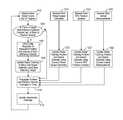
- FIG. 1is a block diagram of a representative platooning control architecture.
- FIG. 2is a flow chart illustrating a method of determining the effective length of a platoon partner based on outputs of a radar unit.
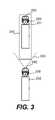
- FIG. 3is a diagrammatic illustration showing the nature of a bounding box relative to a partner vehicle's expected position.
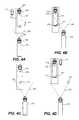
- FIG. 4Ais a diagrammatic illustration showing exemplary radar object points that might be identified by a radar unit associated with a trailing truck that is following directly behind a lead truck.
- FIG. 4Bis a diagrammatic illustration showing a circumstance where the entire lead truck of FIG. 4A is not within the radar unit's field of view.
- FIG. 4Cis a diagrammatic illustration showing a circumstance where the bounding box associated with the lead truck of FIG. 4A is not entirely within the radar unit's field of view.
- FIG. 4Dis a diagrammatic illustration showing a circumstance where the lead truck is in a different lane than the trailing truck, but its entire bounding box is within the radar unit's field of view.
- FIG. 5Ais a graph that illustrates the relative location (longitudinally and laterally) of a first representative set of partner vehicle radar point candidates that might be detected when following a tractor-trailer rig.
- FIG. 5Bis a histogram representing the longitudinal distances of the detected partner vehicle radar point candidates illustrated in FIG. 5A .
- FIG. 5Cis a plot showing the mean shift centers of the histogram points represented in FIG. 5B .
- FIG. 5Dis a graph that illustrates the relative location (longitudinally and laterally) of a second (enlarged) set of partner vehicle radar point candidates that might be detected when following a tractor-trailer rig.
- FIG. 5Eis a histogram representing the longitudinal distances of the detected partner vehicle radar point candidates illustrated in FIG. 5D .
- FIG. 5Fis a plot showing the mean shift centers of the histogram points represented in FIG. 5E .
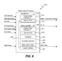
- FIG. 6is a diagrammatic block diagram of a radar scene processor suitable for use by a vehicle controller to interpret received radar scenes.
- FIG. 7is a flow chart illustrating a method of determining whether any particular radar scene reports the position of the back of a partner vehicle and updating the estimator of FIG. 6 .
- FIG. 8is a representation of a Kalman filter state array and covariance matrix suitable for use in some embodiments.
- the Applicanthas proposed various vehicle platooning systems in which a second, and potentially additional, vehicle(s) is/are autonomously or semi-autonomously controlled to closely follow a lead vehicle in a safe manner.
- a second, and potentially additional, vehicle(s)is/are autonomously or semi-autonomously controlled to closely follow a lead vehicle in a safe manner.
- U.S. application Ser. Nos. 13/542,622, 13/542,627 and 14/292,583U.S. Provisional Application Nos. 61/505,076, 62/249,898, 62/343,819, 62/377,970 and; and PCT Application Nos.
- PCT/US2014/030770, PCT/US2016/049143 and PCT/US2016/060167describe various vehicle platooning systems in which a trailing vehicle is at least partially automatically controlled to closely follow a designated lead vehicle.
- One of the goals of platooningis typically to maintain a desired longitudinal distance between the platooning vehicles, which is frequently referred to herein as the “desired gap”. That is, it is desirable for the trailing vehicle (e.g., a trailing truck) to maintain a designated gap relative to a specific vehicle (e.g., a lead truck).
- the vehicles involved in a platoonwill typically have sophisticated control systems suitable for initiating a platoon, maintaining the gap under a wide variety of different driving conditions, and gracefully dissolving the platoon as appropriate.
- FIG. 1diagrammatically illustrates a vehicle control architecture that is suitable for use with platooning tractor-trailer trucks.
- a platoon controller 110receives inputs from a number of sensors 130 on the tractor and/or one or more trailers or other connected units, and a number of actuators and actuator controllers 150 arranged to control operation of the tractor's powertrain and other vehicle systems.
- An actuator interface(not shown) may be provided to facilitate communications between the platoon controller 110 and the actuator controllers 150 .
- the platoon controller 110also interacts with an inter-vehicle communications controller 170 which orchestrates communications with the platoon partner and a NOC communications controller 180 that orchestrates communications with a network operations center (NOC).
- the vehiclealso preferably has selected configuration files that include known information about the vehicle.
- the functional components of the platoon controller 110include gap regulator 112 , mass estimator 114 , radar tracker 116 and brake health monitor 118 . In many applications, the platoon controller 110 will include a variety of other components as well.
- Some of the sensors utilized by the platoon controller 110may include GNSS (GPS) unit 131 , wheel speed sensors 132 , inertial measurement devices 134 , radar unit 137 , LIDAR unit 138 , cameras 139 , accelerator pedal position sensor 141 , steering wheel position sensor 142 , brake pedal position sensor 143 , and various accelerometers.
- GPSglobal navigation satellite systems
- GPSis just one of the currently available global navigation satellite systems (GNSS). Therefore, it should be appreciated that data from any other GNSS system or from other suitable position sensing systems may be used in place of, or in addition to the GPS system.
- sensorsincluding wheel speed sensors, 132 , radar unit 137 , accelerator pedal position sensor 141 , steering wheel position sensor 142 , brake pedal position sensor 143 , and accelerometer 144 are relatively standard equipment on newer trucks (tractors) used to pull semi-trailers.
- otherssuch as the GNSS unit 131 and LIDAR unit 138 (if used) are not currently standard equipment on such tractors or may not be present on a particular vehicle and may be installed as needed or desired to help support platooning.
- Some of the vehicle actuators controllers 150 that the platoon controller directs at least in partinclude torque request controller 152 (which may be integrated in an ECU or power train controller); transmission controller 154 , brake controller 156 and clutch controller 158 .
- the communications between vehiclesmay be directed over any suitable channel and may be coordinated by inter-vehicle communications controller 170 .
- DSRCDedicated Short Range Communications
- the DSRC protocole.g. the IEEE 802.11p protocol
- other communications protocols and channelsmay be used in addition to or in place of a DSRC link.
- the inter vehicle communicationsmay additionally or alternatively be transmitted over a Citizen's Band (CB) Radio channel, one or more General Mobile Radio Service (GMRS) bands, and one or more Family Radio Service (FRS) bands or any other now existing or later developed communications channels using any suitable communication protocol.
- CBCitizen's Band
- GMRSGeneral Mobile Radio Service
- FSSFamily Radio Service
- the transmitted informationmay include the current commands generated by the platoon controller such as requested/commanded engine torque, requested/commanded braking deceleration. They may also include steering commands, gear commands, etc. when those aspects are controlled by platoon controller.
- Corresponding informationis received from the partner vehicle, regardless of whether those commands are generated by a platoon controller or other autonomous or semi-autonomous controller on the partner vehicle (e.g., an adaptive cruise control system (ACC) or a collision mitigation system (CMS)), or through other or more traditional mechanisms—as for example, in response to driver inputs (e.g., accelerator pedal position, brake position, steering wheel position, etc.).
- ACCadaptive cruise control system
- CMScollision mitigation system
- tractor sensor information provided to platoon controlleris also transmitted to the platoon partner and corresponding information is received from the platoon partner so that the platoon controllers on each vehicle can develop an accurate model of what the partner vehicle is doing.
- any other relevant information that is provided to the platoon controllerincluding any vehicle configuration information that is relevant to the platoon controller.
- the specific information transmittedmay vary widely based on the requirements of the platoon controllers, the sensors and actuators available on the respective vehicles, and the specific knowledge that each vehicle may have about itself.
- the information transmitted between vehiclesmay also include information about intended future actions. For example, if the lead vehicle knows it approaching a hill, it may expect to increase its torque request (or decrease its torque request in the context of a downhill) in the near future and that information can be conveyed to a trailing vehicle for use as appropriate by the platoon controller.
- the nature of the expected events themselvescan be indicated (e.g., a hill, or curve or exit is approaching) together with the expected timing of such events.
- the intended future actionscan be reported in the context of expected control commands such as the expected torques and/or other control parameters and the timing at which such changes are expected.
- expected control commandssuch as the expected torques and/or other control parameters and the timing at which such changes are expected.
- expected eventsthere are a wide variety of different types of expected events that may be relevant to the platoon control.
- the communications between the vehicles and the NOCmay be transmitted over a variety of different networks, such as the cellular network, various Wi-Fi networks, satellite communications networks and/or any of a variety of other networks as appropriate.
- the communications with the NOCmay be coordinated by NOC communications controller 180 .
- the information transmitted to and/or received from the NOCmay vary widely based on the overall system design.
- the NOCmay provide specific control parameters such as a target gap tolerance. These control parameters or constraints may be based on factors known at the NOC such as speed limits, the nature of the road/terrain (e.g., hilly vs. flat, winding vs. straight, etc.) weather conditions, traffic or road conditions, etc.
- the NOCmay provide information such information to the platoon controller.
- the NOCmay also provide information about the partner vehicle including its configuration information and any known relevant information about its current operational state such as weight, trailer length, etc.
- the vehicles involved in a platoonwill typically have one or more radar systems that are used to detect nearby objects. Since radar systems tend to be quite good at determining distances between objects, separation distances reported by the radar unit(s) are quite useful in controlling the gap between vehicles. Therefore, once a platooning partner is identified, it is important to locate that specific partner vehicle in the context of the radar system output. That is, to determine which (if any) of a variety of different objects that might be identified by the radar unit correspond to the targeted partner.
- the platoon partnerwill not always correlate to the closest vehicle detected by the radar unit or to the vehicle that is directly in front of the trailing truck.
- the partnermay be out of sight of a host vehicle's radar unit because it is too far away.
- the partnercomes into sight of the radar unit, it becomes important to identify and distinguish that partner from other objects in the radar unit's field of view.
- the description belowdescribes techniques that are particularly well suited for identifying and distinguishing a designated partner from other objects that may be detected by a radar unit so that the radar unit can effectively track the partner vehicle (sometimes referred to as “locking onto” the partner).
- a lead truckmay change lanes at which point it may not be directly in front of the trailing vehicle, so again, it is important for that the distance between the platoon partners reported by the radar unit be associated with the platoon partner rather than merely the closest vehicle or a vehicle that happens to be directly in front of the trailing truck.
- the radar unitmay not be able to “see” the platooning partner. This could be because an interloper has gotten between the platoon partners or the lead vehicle has maneuvered out of view of the trailing vehicle's radar unit, interference with the radar signals, etc.
- the position of the partner vehicleis generally known from the GPS based location information that is transmitted to the host vehicle.
- the GPS systemtypically reports a location on the tractor, which could for example, be the position of the antenna(s) that receive the GPS signals.
- the detected GPS positionmay then be translated to the position of a reference location on the vehicle that is a known distance from the GPS antenna, with the position of that reference location serving as the vehicle's reported GPS position.
- the specific reference location chosenmay vary based on control system preferences.
- the reference locationmay be the center of the rear axles of the tractor.
- the difference between the reported GPS position and the physical back of the vehiclecan be significant to the platoon control. Therefore, it is often important to know the distance between the reported vehicle position and the actual back of the vehicle. This is sometimes referred to herein as the “effective vehicle length.”
- the effective vehicle lengthis particularly important in the context of a tractor trailer truck where the reported GPS position is typically located somewhere on the cab (tractor) and the distance from the reported GPS position to the back of the trailer may be quite long.
- trailer lengths on the order of 12-18 metersare common in the U.S. although they can be shorter or longer (indeed much longer in the context of double or triple trailers).
- the distance from the reported GPS position to the back of the vehiclemust also account for the longitudinal distance from the reported GPS position to the front of the trailer and/or any extensions associate with the load. It should be appreciated that in the trucking industry, the effective vehicle length often will not be known since any particular tractor may pull a variety of different trailers and the attachment point between the tractor and trailer is adjustable on the tractor.
- radar units used in general road vehicle driving automation systemstypically output data that indicates the presence of any object(s) detected within a designated field together with the relative position and speed of such object(s).
- a radar unitmay detect the presence of a variety of objects within its operational field.
- the detected objectsmay include any vehicle positioned directly in front of the host vehicle, vehicles in adjacent lanes that may be passing, being passed by or driving in parallel to the platoon, stationary objects such as obstacles in the road, signs, trees, and other objects to the side of the road, etc.
- the radar unititself typically doesn't know or convey the identity or nature of the detected object. Rather it simply reports the relative position and motion of any and all perceived objects within its operational field.
- the logic interpreting the output of the radar unitto have and maintain a good understanding of exactly where the partner vehicle is expected to be relative to the radar unit's field of view regardless of whether the partner vehicle is even in that field of view. This is possible even when no explicit mechanism is provided for identifying the partner because the platooning system preferably has multiple independent mechanisms that can be used to help determine a vehicle's position.
- a communications linkis preferably established between the platooning vehicles.
- the communicationsmay be established over one or more wireless links such as a Dedicated Short Range Communications (DSRC) link, a cellular link, etc.
- DSRCDedicated Short Range Communications
- the processes used to identify potential platoon partners and to establish the platoon and appropriate communication linksmay vary widely. By way of example, a few representative techniques are described in U.S. patent application Ser. Nos. 13/542,622 and 13/542,627 as well as PCT Patent Application Nos. PCT/US2014/030770, PCT/US2016/049143 and PCT/US2016/060167 previously filed by Applicant, each of which is incorporated herein by reference.
- the platoon controller 110requests the radar system control logic attempt to find the partner vehicle. More specifically, the trailing vehicle's radar tracker 116 needs to find and thereafter track the back of the lead vehicle in the context of the radar unit's outputs so that its data can be used in gap control.
- FIG. 2a method particularly well suited for establishing a radar fix on a platoon partner will be described.
- One aspect of establishing a radar fixis to determine the length of the partner so the GPS position information can be correlated to radar system outputs.
- radar tracker control logicdetermines, receives or requests an estimate of the current relative position of the partner vehicle and subscribes to or regularly receives updates regarding the partner vehicle's relative position as they become available as represented by step 203 of FIG. 2 .
- the estimated informationmay optionally include various additional position related information such as relative velocity of the vehicles, the relative heading of the vehicles, etc.
- the radar tracker control logicis configured to estimate the current relative position, velocity and orientation (heading) of the partner vehicle based on a variety of sensor inputs from both the host vehicle and the partner vehicle.
- the platoon partnersare in communication with one another and during platooning, they send extensive information back and forth about themselves, including continually updated information about their current location and operating states.
- some of the location related information that can be helpful to interpreting radar unit datamay include information such as the partner vehicle's GPS position, wheel speed, orientation/heading (direction that the vehicle is heading), yaw rate (which indicates the vehicle's rate of turn), pitch, roll and acceleration/deceleration (longitudinal and angular in any of the forgoing directions).
- Operational related informationmay also include a variety of other information of interest such the current torque requests, brake inputs, gear, etc.
- Information about the vehiclesmay include information such as the make and model of the vehicle, its length (if known), its equipment, estimated weight, etc. Any of these and/or other available information can be used in the position related estimates. By way of example, one particular position estimator is described below with respect to FIGS. 6 and 7 .
- the estimated partner vehicle position related informationcan come from any appropriate source and the estimation does not need to be made by the radar tracker control logic itself. Additionally, although it is preferred that position and operational information be transmitted in both directions between vehicles, that is not necessary as long as the host vehicle is able to obtain the required information about the partner vehicle(s).
- the current location related informationis updated very frequently.
- update frequencies for itemssuch as GPS position and wheel speed received over a DSRC link at frequencies on the order of 10 to 500 Hz, as for example 50 Hz work well although slower and much faster update frequencies may be used as appropriate in other embodiments.
- regular updates of the location related informationare desirable, there is no need that they be received synchronously or at consistent intervals.
- the partner vehiclesmay or may not be within the radar unit's field of view.
- both the host vehicle's position and the partner vehicle's positionare generally known based at least on the received GPS data so it is easy to estimate their separation with reasonable certainty.
- GPS location signalstend to be pretty good, the reported locations may be off by some amount and thus it is better to treat any reported GPS position as an estimate with some appropriate amount of uncertainty rather than treating the reported position as infallible information. More details regarding some specific algorithms that are suitable for estimating the partner vehicle position will be described in more detail below.
- GPS position readings from commercially available GPS sensors used in vehicle automation applicationstend to be accurate within about 2-3 meters in practical road conditions when there is a direct line of sight to at least 4 GPS satellites.
- some GPS sensorsare regularly more precise and no GPS sensors are guaranteed to always be that accurate due to variables such as interference, operations is regions where there is not line of sight visibility to the required number of operational GPS satellites, etc.
- a bounding boxis applied around the estimated relative position of the partner (step 206 of FIG. 2 ).
- the purpose of the bounding boxis to define a region that the partner vehicle is “expected” to be found in.
- the logicwill thereafter look for radar detected objects located within that bounding box in an effort to identify objects that may correlate to the partner vehicle.
- the concept of a bounding boxis helpful for several reasons. Initially it should be appreciated that the GPS unit will typically report the location of its antenna, which in the context of a tractor-trailer truck is usually on the cab. This detected position is then typically translated to a predefined reference location on the tractor and that translated position is used as the reported GPS position.
- the reported GPS position for a tractor-trailerwill be well in front of the back of the trailer which is (a) the point that is of primary interest to the gap control purposes, and (b) is typically the most prominent feature identified by the radar unit from a trailing platoon partner.
- the distance between the reported GPS position and the back of the trailerwill not be known in many circumstances.
- One reason for the uncertaintyis that a particular tractor (cab) may be used to pull a variety of different trailers (or other loads) which potentially have different lengths. Therefore the effective length of the tractor-trailer combination may vary from trip to trip and from a control standpoint it is generally undesirable to count on the driver to manually input the effective length of the tractor-trailer combination each trip.
- the reported GPS positions of both platoon partnersare subject to a degree of uncertainty.
- the actual size and geometry of the bounding box usedmay vary but it is desirable that the region be large enough to encompass the entire range of vehicle lengths and widths that are possible plus a buffer to account of uncertainty in the estimated GPS position.
- the longitudinal length of the bounding boxbe longer than any tractor-trailer combination that might be expected to be encountered.
- U.S. commercial trucking applications involving normal tractor trailer combinationstypically don't significantly exceed a combined length of 23 meters.
- bounding boxes on the order of 32 meters long and 3-4.5 meters, as for example 3.8 meters widehave been found to work well.
- the tractor-trailer combinationsmay be longer and therefore longer bounding boxes may be appropriate.
- the size of the bounding boxcan be adjusted accordingly to more accurately reflect the expected offset between the GPS position and the back of the trailer—which correlates to the effective vehicle length.
- the effective length and width of the platoon partneris “known,” it is still desirable to utilize a bounding box greater in size than the reported length and width to accommodate uncertainty in the GPS estimates and the possibility that the load may include a feature that extends beyond the vehicle's reported length.
- the bounding boxmay encompass any desired geometric shape and/or may include dimensions other than longitudinal length and lateral width—as for example relative velocity.
- the bounding boxmay be defined in any desired manner.
- FIG. 3A representative bounding box 255 applied around a lead truck 251 in a platoon of two trucks is diagrammatically illustrated in FIG. 3 .
- each truckhas a GPS unit 258 located on its tractor (cab) and a radar unit 260 located at the front of the cab. It can be seen that the bounding box exceeds the length and width of the lead truck 251 .
- the bounding boxmay be defined more complexly.
- the scaled squares of the lateral offset (Y off ) and the relative velocity (V) of the vehiclesmay be compared to a threshold (Th).
- Tha threshold
- a radar pointwould then be rejected if the sum of these squares exceeds the designated threshold (Th), even if the radar point is within the longitudinal range of the bounding box.
- the logicdetermines whether the entire bounding box is within the other vehicle's radar unit's field of view 263 (step 209 ). If not, the logic waits for the entire bounding box to come within the radar unit's field of view thereby effectively ignoring the radar system outputs for the purpose of identifying the partner vehicle (although of course the radar system outputs can be used for other purposes such as collision avoidance if desired). There are a variety of reasons why the partner vehicle may not be within or fully within the radar units field of view at any particular time. Initially, it should be appreciated that although the radar unit(s) used to support platooning may be placed at a variety of different locations on the vehicles, they often have a relatively narrow field of view.
- one common approachis to place a forward facing radar unit having a relatively narrow fixed beam in the vicinity of the middle of the front bumper to detect objects in front of the vehicle.
- a forward facing radar unit having a relatively narrow fixed beamis illustrated in FIG. 3 .
- the field of view 263 of radar unit 260 located on the trailing truck 252is also shown.
- a forward facing radar unitWhen a forward facing radar unit is used, it will be unable to see any vehicle behind or to the side of its host vehicle. Even when the partner vehicle is ahead of the radar unit host, it may be out of the field of view if it is too far ahead of the host or is around a corner—as may be the case when a platoon partner is first identified. In some cases a platoon partner can be partially in the radar unit's field of view. A common example of this is when the partner vehicle in an adjacent lane and not far enough ahead for the back of its trailer to be seen by a narrow beamed forward facing radar unit.
- FIGS. 4A-4Dillustrate a few (of the many) potential relative positioning of two trucks that are in the process of establishing a platoon.
- the lead truck 251is directly ahead of the trailing truck 252 and its bounding box 255 is fully within the field of view 263 of trailing truck radar unit 260 .
- the lead truck 251is in a lane adjacent the trailing truck 252 and some, but not all of the lead truck 251 itself (and thus not all of bounding box 255 ) is within the field of view 263 of trailing truck radar unit 260 .
- FIG. 4Athe lead truck 251 is directly ahead of the trailing truck 252 and its bounding box 255 is fully within the field of view 263 of trailing truck radar unit 260 .
- the lead truck 251is in a lane adjacent the trailing truck 252 and some, but not all of the lead truck 251 itself (and thus not all of bounding box 255 ) is within the field of view 263 of trailing truck radar unit 260 .
- the lead truck 251is in a lane adjacent to the trailing truck 252 and all of the lead truck 251 itself, but not the entire bounding box 255 , is within the field of view 263 of trailing truck radar unit 260 .
- the lead truck 251is again in a lane adjacent the trailing truck 252 but differs from FIGS. 4B and 4C in that the entire bounding box 255 associated with lead truck 251 is within the field of view 263 of trailing truck radar unit 260 .
- the partner vehicle identification logicwaits at step 209 for the entire bounding box to come within the radar unit's field.
- the radar system controller logicobtains a next radar sample (step 212 ) and a current estimate of the partner vehicle's position and velocity relative to itself (step 215 ).
- a next radar samplestep 212
- a current estimate of the partner vehicle's position and velocity relative to itselfstep 215 .
- Commercially available short range radar units utilized in road vehicle applicationsare typically configured to output their sensed scene at a relatively rapid sample rate. Each scene typically identifies a set of zero or more objects that have been detected as well as the velocity of such objects relative to the radar unit itself.
- the nature of radar systemsis that the transmitted radio waves can be reflected by most anything in their path including both any intended target(s) and potentially a wide variety of different items. Therefore, when trying to establish a platoon, it is important to identify the reflected signal(s) that represent the desired partner and to be able to distinguish that partner from the noise reflected from other objects.
- the radar unitmay receive reflections from multiple different vehicles including any vehicle that is immediately ahead, passing vehicles going in the same or opposite direction objects to the side of the road such as highway or street signs, trees or other objects along the side of the road, etc.
- the radar system control logicdetermines whether any of the identified objects are partner vehicle radar point candidates as represented by step 218 .
- Representative objects that might be detected by the radar unit 260are marked with X's in FIGS. 4A-4D .
- an object detected in the scenemust be located within the bounding box in terms of both position and speed. Radar objects located outside of the bounding box are preferably rejected because there is a relatively higher probability that they do not correspond to the partner vehicle. For example, they could correspond to vehicles in adjacent lanes 272 , 273 , an interloper located between the platoon partners (not shown), objects on the side of the road 274 , etc.
- Objects that do not closely match the expected relative speed of the partner vehicleare also preferably rejected even if they match the expected position aspects of the bounding box longitudinally and laterally because again, it is less likely that they correspond to the platoon partner.
- a stationary objectsuch as a feature to the side of the road (e.g. a road sign, tree or stationary vehicle), debris in the road, or a detected feature in the road itself (e.g. a pothole, etc.), will appear to be approaching the radar unit at the speed that the host vehicle is traveling at. It is noted that many commercially available radar units will automatically filter out, and therefore don't report, stationary objects. When such a radar unit is used, the stationary objects would not even be identified as part of the radar scene.
- Some of the reported radar objectsmay be traveling in the same direction as the host vehicle but are moving at a relative velocity that is different than the expected partner velocity. There is a relatively high probability that such radar objects do not correspond to the partner vehicle and therefore these types of radar points are also preferably discarded.
- any detected radar objects that appear to match the expected location and speed of the partner within the context of the defined bounding boxare considered partner vehicle radar point candidates and are categorized with respect to how far they are longitudinally (along the longitudinal axis of the partner) from the estimated location of the partner (e.g., the partner's GPS position).
- a histogramis utilized for to this categorization. The number of bins in the histogram may vary. For computational ease, 512 bins divided evenly over the length of the bounding box has been found to work well, although more or less bins can be used as appropriate for any particular application. In implementations that use a bounding box of approximately 32 meters, with 512 bins, each bin corresponds to approximately 6 cm (2-3 inches). If greater resolution is desired, then more bins can be used.
- the radarwhen the radar is mounted relatively low on the host vehicle it may detect reflections from the transmission or other items along the truck's undercarriage or other features of the tractor-trailer such as the trailer's landing gear or the back of the tractor and identify those items as separate detected “objects.” Therefore, it is possible (indeed it is relatively common) that any particular sample may identify more than one object that meets the criteria of a partner vehicle radar point candidates. In such circumstances multiple candidates associated with a particular radar sample will be added to the histogram.
- step 224a determination is made regarding whether sufficient samples have been obtained to analyze the radar data to identify the partner vehicle in step 224 . If not, the logic returns to step 212 where the next sample is obtained and the process repeats until sufficient samples have been obtained to facilitate analysis. If the bounding box moves partially out of the field of view of the radar unit at any point (as represented by the “no” branch from decision block 225 ), then the logic returns to step 209 where it waits for the bounding box to come back into full view before taking additional samples.
- FIG. 5Ais a plot showing a set of 98 detected partner vehicle radar point candidates transposed into a reference frame based on the expected location of the front truck.
- the x-axis of the plotshows the longitudinal distance from the expected position of the front of the leading truck to the detected point.
- the y-axisshows the lateral offset of the detected point relative to the center axis of the leading truck. It can be seen that although there is noticeable variation in the locations of the detected points, in the illustrated sample set, the points tend to be clustered into a couple of regions.
- FIG. 5Bis a histogram that shows the longitudinal distance to each of the detected partner vehicle radar point candidates in the plot of FIG. 5A . It can be seen that when only the longitudinal distance is considered, the clustering tends to be even more pronounced.
- the large cluster 290 located furthest back in the histogramtypically corresponds to the back of the vehicle and is often (although not always) the largest cluster.
- Cluster 292 located further forwardtypically correspond to other features of the partner truck.
- radar reflections from the forward featurestend to be weaker and more sporadically identified as a discrete object by the radar unit, which translates to a smaller cluster in the histogram.
- the logicfollows the yes branch from decision block 224 and flows to step 227 where a clustering algorithm is applied to the histogram data.
- the trigger point for when processing may startcan vary widely based on the needs of any particular system. In general, it is desirable for the histogram to contain enough data points so that the partner vehicle can be accurately identified. In some specific implementations, the histogram must include data from a first threshold worth of samples (e.g., samples corresponding to at least 3 seconds worth of data or 60 samples) and include at least a second threshold worth of partner vehicle radar point candidates (e.g., at least 60 partner vehicle radar points). The thresholds used may vary based on the needs of a particular implementation.
- samples corresponding to at least 1-5 seconds worth of data or thresholds in the range of 40 to 500 pointsmay be used in some implementations.
- samples corresponding to at least 3 seconds worth of data or 60 samples and 60 partner vehicle radar pointsare used as thresholds.
- the dataset illustrated in FIGS. 5A and 5Bis representative of a dataset that might be available at the time that an attempt is initially made to identify the back of the partner vehicle—that is, the first time that the “yes” branch from step 224 is followed.
- FIG. 5Cis a plot showing the mean shift centers of the histogram points represented in FIG. 5B , with the heights of the centers being indicative of the number of points associated with that center.
- the two clusters 290 and 292stand out even more dramatically in this representation.
- the mean shift datais then analyzed to determine whether one of the clusters meets predefined back of partner vehicle criteria in step 230 . If so, that cluster is identified as corresponding to the back of the vehicle. (Step 233 ). Since each cluster corresponds to a designated distance between the partner's reported GPS position and the back of the vehicle, the effective length of the vehicle is defined by the cluster. As noted above, the phrase “effective vehicle length” as used herein corresponds to the distance between the reported GPS position and the back of the vehicle—which is an important distance to know for control purposes. It should be appreciated that this is typically different than the actual length of the vehicle because the reported reference position may not be located at the front of the vehicle.
- the cluster located closest to the back of bounding box that has over a threshold percentage of the total number of radar points in the histogramis identified as back of the platoon partner vehicle.
- a further constraintis used that requires that the cluster location not move by more than a certain threshold on the last sample.
- maximum movement thresholds on the order of 1 mmhave been found to work well in some applications. This approach has been found to very reliably identify the radar point that corresponds to the back of a truck even when the radar unit controller has no predetermined knowledge of the length of the vehicle and regardless of the presence of other traffic.
- the threshold percentage or other characteristics of the histogram used to identify the back of the vehiclemay vary based on application.
- cluster 290is designated as the back of the lead truck.
- Radar points that report features that are not where the platoon partner is expected to beare filtered because they are not within the bounding box. Radar points that are not traveling at close to the expected relative speed are filtered regardless of where they are found.
- the back of vehicle criteria used on the clustered histogram dataeffectively filters any other vehicles traveling within the footprint of the bounding box at very near the same speed as the platoon partner because the bins are small enough that it is highly unlikely that such an interloper can maintain a constant enough gap to fool the algorithm into thinking that the interloper is part of the target (e.g., even if the interloper is traveling at nearly the same speed as the partner vehicle, if it is located within the bounding box, it's position relative to the partner vehicle's position is likely to vary enough to cause the back of partner vehicle test to fail.
- the back of vehicle criteriaalso filters out more random objects reported by the radar unit.
- the effective vehicle length indicated by the selected mean shift clustermay be reported to the gap controller and any other controller concerned with the length of the partner.
- the distance between the GPS reference location and the front of the host vehicleis known and therefore the effective vehicle length determined by the radar unit can readily be used in association with known information about the truck to positively indicate the front and back of the truck as represented by step 236 .
- radar pointsmay optionally be discarded after they become too old or the process restarted if the system has trouble identifying the back of the partner vehicle or for other reasons, such as the vehicles coming to a stop.
- the back of the partner identification processcontinues to run or is periodically rerun even after the vehicle length has been determined.
- the initial length determinationis made while the platoon partners are relatively far apart (e.g., over 100 feet).
- the gap controllermay tighten the gap thereby drawing the vehicles closer together.
- the radar readingare often more precise than they are when the vehicles are 100+ feet apart.
- more measurementgive a better statistical indication of the relative position of the vehicle.
- FIG. 5Dis a plot showing a set of 1700 detected partner vehicle radar point candidates on the same graph as shown in FIG. 5A .
- the 1700 sample pointsinclude the 98 points illustrated in FIGS. 5A-5C and were obtained by continuing to run the same radar point classification algorithm.
- FIGS. 5E and 5Fshow the histogram and mean shift centers respectively for the larger data set.
- FIG. 5Ecorresponds to FIG. 5B
- FIG. 5Fcorresponds to FIG. 5C . It can be seen that the larger dataset appears to have identified a small cluster 293 located near the front of the lead vehicle and has effectively filtered out some smaller clusters identified in the smaller data set.
- the histogram and/or mean shift clustersalso provide a very good indication of the radar signature of the partner vehicle.
- This known signature of the partner vehiclecan be used in a number of different ways as an independent mechanism for verifying that the proper vehicle is being tracked. For example, in scenarios where GPS data becomes unavailable or communications between the vehicles are disrupted for a period of time, the histogram can be used as a check to verify that the correct vehicle is being tracked by the radar unit.
- the portion of the truck that can be seencan be compared to the histogram signature to determine the relative positioning of the trucks, which can be used as a measurement for gap control or as part of autonomous or semi-autonomous control of the trailing vehicle.
- a new histogramin circumstances when radar contact is lost, can be started at an appropriate time and a new histogram can be compared to a stored histogram indicative of the platoon partner. When there is a match, that match can be good independent evidence that radar contact with the platoon partner has been reestablished.
- newly created histogramscan be compared to stored histograms representing the platoon partner at various times during platooning as a way of independently verifying that the platoon partner is still being tracked. This can be a good safety check to verify that the radar unit has not inadvertently switched and locked onto a vehicle that is traveling in parallel next to the platoon partner.
- the histogramscan also be saved as a radar signature of the partner vehicle and shared with other trucks that may later seek to platoon with that vehicle—which can be useful in the initial identification process.
- Such modelspreferably utilize inputs from multiple different sensing systems and include at least some redundant information from different systems when practical.
- the provision of redundant information from different systemsis helpful as a double check as to the integrity of received data and also provides backup mechanisms for the inevitable times when a system is unable to convey accurate information.
- the gap between vehiclescan be determined using a number of different techniques.
- One general approachis to use the distance to the platoon partner detected by the radar system. Although radar tends to very accurately measure the distance between vehicles, it is important to ensure that the distance being reported is actually the distance to the platoon partner rather than some other vehicle or feature. There are also times when the partner vehicle is not within the radar's field of view or the radar or the radar unit is not operating as desired for a brief period.
- An independent way of determining the distance between the platoon partnersis to utilize their respective GPS data. Specifically, the distance between the vehicles should be the difference between the vehicle's respective GPS positions, minus the effective length of the lead vehicle and the offset distance between the front of the trailing vehicle and its GPS receiver.
- GPS dataLimitations of using the GPS data include the fact that the GPS data will not always be available due to factors such as the GPS receivers not having a clear view of sufficient GPS satellites to be able to determine a location or the communication link between vehicles being down for a period of time.
- the GPS datais also fundamentally limited by the fact that the accuracy of the GPS data, which while good, is often less precise than desired for gap control.
- Other systems for measuring distances between the platoon partnershave their own advantages and limitations.
- the gap expected at a time in the immediate futurecan be estimated based on factors such as the current positions, the relative velocities and yaw rates of the vehicles.
- the respective velocities of the vehiclesmay also be measured, determined, estimated and/or predicted in a variety of different manners.
- wheel speed sensorscan be used to relatively accurately indicate the current speeds of the respective vehicles.
- Knowledge of the vehicle's orientationcan be used in conjunction with the knowledge of the vehicle's speed to determine its velocity.
- the radar unitcan be used to measure the relative speeds of the platoon partners. Knowledge of other factors such as torque request, vehicle weight, engine characteristics and road grade can be used to predict vehicle speeds in the future.
- the radar system controller(or another controller whose determinations can be utilized by the radar system controller) includes a position estimator that maintains an estimate of the current position, orientation and relative speed of the partner vehicle relative to the radar unit.
- a position estimatorthat maintains an estimate of the current position, orientation and relative speed of the partner vehicle relative to the radar unit.
- One suitable radar scene processor 600 that includes a position/state estimator 612is illustrated in FIG. 6 .
- radar scene processor 600includes gap monitor 610 and a partner identifier 620 .
- the gap monitor 610is configured to track the position of the back of the partner vehicle based on radar measurements (after the back of the partner vehicle has been identified) and to report radar position and speed measurements corresponding to the back of the partner vehicle to the gap controller and/or any other component interested in such measurements made by the radar unit.
- One particular implementation of the gap monitoring algorithmwill be described below with reference to the flow chart of FIG. 7 .
- the gap monitor 610includes a position/state estimator 612 having a Kalman filter 615 that is used to determine both the most recent estimate of the position of the partner vehicle relative to the host vehicle and to predict the expected position of the partner vehicle at the time the next radar sample will be taken.
- the position/state estimator 612utilizes both the detected radar scenes and other available vehicle state information such as the respective GPS positions, wheel speeds, and inertial measurements of the host and partner vehicles in the estimate of the expected state (e.g. position, velocity etc.) of the leading vehicle. These state estimates can then be used to help interpret the received radar scene.
- the gap monitor 600properly identify the radar return object that corresponds to the back of the partner vehicle out of a radar scene that may include a set of detected objects. This helps ensure that the proper detected point is used in the gap control. It is also helpful in identifying situations in which the tracker does not have good confidence regarding which (if any) of the objects detected by the radar in a particular scene sample accurately represent the position of the back of the partner vehicle so that such a sample can be discounted, ignored or otherwise properly handled in the context of the gap control algorithm.
- One particular Kalman filter designthat is well suited for use in the position/state estimator 612 is described below with respect to FIG. 8 .
- the partner identifier 620includes its own position/state estimator 622 , a histogram 624 , a clustering algorithm 625 which produces mean shift clusters 626 and partner length estimator 627 .
- the partner identifier 620executes an algorithm such as the algorithm discussed above with respect to FIG. 2 to identify the back of the partner vehicle. As part of that process, histogram 624 is populated.
- the histogramis diagrammatically shown as being part of the partner identifier 620 , but it should be appreciated that the histogram is merely a data structure that can be physically located at any appropriate location and may be made available to a variety of other processes and controllers within, or external to, the radar tracker 620 .
- the partner length estimator 624is configured to determine the length of the partner vehicle (including its front and back relative to its GPS reference position) based on the histogram and other available information.
- the position/state estimator 622 in the partner identifier 620functions similarly to the position/state estimator 612 describe above and may also include a Kalman filter 623 .
- a significant difference between position state estimator 622 used for partner identification and position/state estimator 612is that what radar point corresponds to the back of the partner truck is not known during identification and therefore the radar unit samples cannot be used as part of the position/state estimates.
- the position/state estimation, partner detection, partner length estimating and gap monitoring algorithmsmay be executed on a radar tracking processor dedicated to radar tracking alone, or they may be implemented on a processor that performs other gap or platoon management tasks as well.
- the respective algorithmsmay be implemented as distinct computing processes or they may be integrated in various manners with each other and/or other functionality in various computing processes. In other embodiments, discrete or programmable logic may be used to implement the described functionality. It should be apparent that a wide variety of different models can be used to track the position of the back of the partner vehicle relative to the radar unit and to estimate future positions.
- Two particular position/state estimatorsare diagrammatically illustrated as part of FIG. 6 and a method that can be used to estimate the current position at any given radar sample time is illustrated in the flow chart of FIG. 7 .
- the trailing vehicleis tracking the position of the back of a lead vehicle, although an analogous process can be used by the lead vehicle to track a following vehicle or for parallel vehicles to track one another.
- the described methodpresupposes that we have a reasonable estimate of the location of the back of the partner vehicle—which can initially be determined using the method described above with respect to FIG. 2 or in any other suitable manner. For example, when the effective length of the front vehicle is known, the initial estimate for the relative position of the back of the lead vehicle can be estimated based on GPS position data.
- One way to determine whether a matching targetis to quantify an uncertainty factor in association with the estimated position. If a radar target point is within the range of the uncertainty factor of the expected position, then it can be considered a match.
- Kalman filteringis used to estimate the position of the back of the partner vehicle and to quantify the uncertainty. Kalman filtering is particularly appropriate because it inherently adjusts the uncertainty level based on the perceived accuracy of the measurements.
- the closest radar object point identified in the radar sceneis treated as the “matching” target.
- the “closest” matchmay be selected based on a combination of metrics including longitudinal position, lateral position, relative speeds, etc.
- the radar trackertransmits the distance to the matched object and relative speed of the matched object to the gap controller 112 as the current gap to and relative speed of, the back of partner vehicle (step 506 ).
- the only information transmittedis the longitudinal distance to the back of the trailer and its relative speed. This is because while currently available radar units are generally quite good at measuring distance and relative speed, they are not as good at precisely measuring lateral velocities or providing precise lateral position information regarding identified objects. However, if the radar unit used can accurately measure other useful attributes of the target such as lateral velocities, acceleration, etc.,—that information may optionally be transmitted as well.
- the best matched targetis used to update the radar tracking position and speed estimate for the back of the truck as well (step 508 ).
- the position and speed estimateis then propagated in time to the position expected for the next radar sample in step 510 . That is, the logic estimates the expected position of the back of the truck at the time the next radar sample is expected. This is a relatively simple matter since the radar samples are provided at regular intervals so the timing of the next expected sample is easy to determine. For example, if the radar sample rate is 20 Hz, the next sample can be expected to occur 0.05 seconds after the last sample.
- the front and rear vehiclesare traveling at exactly the same velocity and both vehicles are traveling in the same direction, than the “expected” position of the back of the front vehicle would be exactly the same as the last detected position of the back of the front vehicle.
- vehicleswill be traveling at slightly different speeds and possibly in slightly different directions if one of the vehicles is turned or turning slightly relative to the other. For example, using a simple example, if the trailing vehicle is moving in exactly the same direction as the lead vehicle at a constant velocity of 1.00 meters per second faster than the lead vehicle, then the back of the lead vehicle would be expected to be 5 cm closer to the lead vehicle at the time the next radar sample is taken (0.05 seconds after the last sample was taken).
- Simple trigonometrymay be used to determine the expected position if the vehicles are turned or turning slightly with respect to one another.
- any number of other relevant variables that are known to or obtainable by the radar system controllercan be considered in the calculation of the expected position and speed to further improve the estimates. These might include the respective accelerations (measured or estimated) of the vehicles, the respective directions of travel and/or rates of turn of the two vehicles, etc. Factors that may influence the velocity, acceleration or rate of turn of the vehicles such as the respective vehicles torque requests, the current grade, the vehicle weights, etc. may also be used to further refine the estimate.
- the uncertainty estimateis updated as represented by block 512 as described in more detail below.
- step 504which utilizes the then current estimate of the position of the back of the lead vehicle to determine whether a match occurs.
- the current estimate of the position of the lead vehiclecan be expected to (indeed likely will) change over time.
- the then current best estimate of the position of the back of front vehiclemay be used which helps ensure that the partner vehicle is accurately tracked.
- the platoon systempreferably utilizes multiple independent or partially-independent mechanisms for tracking the position and speed, of the respective vehicles.
- the platoon controllermay have access to GPS position data which provides an independent mechanism for determining the relative positions of the platooning vehicles.
- the platoon controllermay also have access to wheel speed data which provides an alternative mechanism for determining the respective speeds, and thus the relative speed of the platoon partners.
- Such data for the host vehicleis available from the host vehicle sensors.
- Data for the partner vehiclesis available over the communications link (e.g. the DSRC link, a cellular link or any other available communication method).
- the radar tracking position and speed estimateis updated using the current GPS position estimate (step 523 ), and that updated position and speed estimate is propagated in time to the expected receipt of the next radar sample as represented by step 510 .
- the radar tracking position and speed estimateis updated using the current wheel speed estimates (step 533 ), and that updated position and speed estimate is propagated in time to the expected receipt of the next radar sample as represented by step 510 .
- the GPS position, wheel speed and inertial measurementsare preferably updated on a relatively rapid basis—which is often (although not necessarily) more frequent than the radar samples.
- GPS update frequenciesin the range of 25 to 500 Hz, as for example 50 Hz have been found to work well for open road platoon control applications.
- Similar wheel speed and inertial measurement update frequencieshave also been found to work well—although there is no need to update the GPS positions, wheel speed and/or inertial measurements at the same sample rate as each other, or at the same sample rate as the radar unit.
- the updates from the radar unit, the GPS sensors, the wheel speed sensor and inertial measurementsare handled asynchronously as they are received. Although not required, this is useful to help ensure that the latest sensor inputs are utilized in estimating the expected relative positions and speeds of the platooning vehicles at the time the next radar unit scene sample is received. This is contrasted with a system in which the wheel speed sensor and GPS sensor information is updated once each sample of the radar unit. Although synchronous updates can also work well, the use of asynchronous updates tends to improve the accuracy of the estimates because various sensor inputs can be updated more frequently than the radar unit sampling rate.
- the same types of measurements on the different trucksare preferably synchronized in time. That is, GPS position measurements on the front truck are preferably synchronized in time with GPS position measurements on the back truck so that the relative positions of the trucks can be determined at a particular instant in time.
- the wheel speed measurements on the front truckare preferably synchronized in time with wheel speed measurements on the back truck so that the relative speeds of the trucks can be determined at a particular instant in time.
- the various inertial measurementsare also preferably synchronized with each other as well.
- the GPS systemprovides very accurate global timing signals.
- the clocks used for the platoon partnerscan be synchronized with the GPS signals and the various measurements (e.g. GPS position measurements, wheel speed measurements, inertial measurements, etc.) can therefore be instructed to occur at specific synchronized times on the respective trucks.
- Each measurementmay also be accompanied by a timestamp that indicates when the measurement was taken so that the synchronization of the measurements can be verified (or accounted for if similar sensor measurements are not synchronized between vehicles).
- step 504utilizes the then current estimate of the position of the back of the lead vehicle to determine whether any of the received radar sample object points (targets) match the expected position of the back of the partner vehicle. It should be appreciated that there may be times when no radar sample targets match the expected position of the back of the partner vehicle as represented by the “no” branch from decision 504 . In such cases the radar system controller still propagates the position estimate in time (step 510 ) so that the position estimate is updated for the next radar sample based on the other information the controller has. Such other information includes the then current estimates and may be further updated based on inputs from other systems (e.g., the GPS or wheel speed sensor) as previously discussed.
- other informationincludes the then current estimates and may be further updated based on inputs from other systems (e.g., the GPS or wheel speed sensor) as previously discussed.
- the radar unitwill be shaken accordingly and any radar measurement samples taken at that instant are less likely to be accurate and/or useful to the model.
- Other sensorssuch as the wheel speed and inertial measurement sensor are less likely to be accurate at such times as well.
- the lead truckis aggressively braking it is more likely that its trailer will move back and forth more than usual which again suggests that any radar samples taken during such braking are less likely to be useful for predicting the future position of the back of the trailer.
- the controllerdetects, or is informed, that an event is occurring that makes the measurements of any particular sensor suspect, the measurements from such sensor(s) can safely be ignored in the context of the position estimate.
- inputs from other sensors deemed more reliable (if any)may continue to be used to update the position model and the position estimate may continue to be propagated in time for each subsequent sample.
- the uncertainty associated with position estimatecan be expected to increase slightly with each ignored sample, which has the effect of increasing the variation from the estimated position of the back of the partner vehicle that would be tolerated when determining whether there is a target that matches the expected position of the back of the partner vehicle.
- the position model described aboveis relatively simple in that it utilizes a relatively small set of measured inputs including (1) the received radar scenes (which show the relative position and relative velocity of detected objects); (2) measured GPS positions of the platoon partners (which can be used to determine their relative positions); (3) measured wheel speeds of the platoon partners (which can be used to determine their relative speeds); and (4) measured yaw rate and orientation.
- the position modelcan be adapted to utilize whatever relevant information is available to it in the position estimates. For example, if the pitch or roll of the vehicles are available, the position model can incorporate such measurements into the position estimates.
- the rollcan be useful because on trucks the GPS antennas tend to be located on top of the cabs at locations over 4 meters above the ground (e.g. 14-15 feet). At such heights, even relatively small tilting in the roll direction can cause the reported position of the respective vehicles to vary significantly.
- the pitchcan be useful for similar reasons. For example, with a platooning gap of 15 meters, a difference in pitch of just ⁇ 2 degrees can result in a difference of a meter in the apparent or detected height of an object. At further distances and/or larger pitch variations, those differences are amplified. Since many radar units used in platooning systems have relatively narrow views this can lead to expected objects not being detected, or detected objects being discarded, because they are further from the estimated position than expected when pitch is not considered. Similarly, if longitudinal and/or angular accelerations are available, the position model can incorporate the acceleration measurements into the position estimates.
- the relative positioning and/or speed and/or orientation of the vehiclescan relatively accurately be measured using other systems such as LIDAR, sonar, other time of flight distance sensors, sensors configured to receive a signal transmitted from another vehicle, cameras, stereo cameras or other appropriate technologies, those measurements can be incorporated into the position model in addition to, or in place of, the GPS, wheel speed and inertial measurements.
- the position modelcan be considerably more sophisticated using inputs such a torque requests, braking signals and/or other operational information about the respective platoon partners to further refine the predicted position at the time of the next radar sample.
- the radar sample object pointsare compared to the estimated (expected) position and relative speed of the back of the partner vehicle.
- more or fewer parameterscan be compared to identify a match.
- matchesmay be based on matching the expected position of the partner vehicle rather than position and speed/velocity. If the radar unit is capable of reliably reporting other information such as acceleration, rates of lateral movement, etc., then such information can also be compared to corresponding estimates as part of the match identification 504 .
- a significant advantage of the described approachis that the relative position and velocity estimates can reliably continue even when the back of the platoon partner is outside the view of the radar unit—as may sometimes be the case when the lead vehicle changes to a different lane, an interloper cuts in between the platooning vehicles, or a transitory fault occurs with the radar unit.
- radar identification of the platoon partnercan more easily be reestablished when the back of the platoon partner comes back into the radar unit's view.
- thisis very different than adaptive cruise control systems that utilize radar only to track the distance to the vehicle directly in front of the host vehicle—regardless of who that leading vehicle may be.
- histogram and/or mean shift clusters described above with respect to FIG. 5can be used as another check to verify that the correct vehicle is being tracked by the radar unit or to provide a reference point when some, but not all of the truck is within the radar unit's field of view.
- a noteworthy feature of the method described with respect to FIG. 7is that the same algorithm(s) can be used to estimate the relative position/velocity of the partner vehicle during the initial radar identification of the partner vehicle as described above with respect to FIG. 2 .
- the radar tracker 116 / 600would not have a good estimate of the position of the back of the partner vehicle.
- no targetwould match the expected position of the back of the partner vehicle at decision point 504 so no measured position would be reported to the gap controller and the radar unit's measurements would not be used to update the position and speed estimates—thereby following the “no” branch from decision point 504 which causes steps 506 and 508 to be skipped.
- the other available sensorsincluding the GPS sensors 131 , the wheel speed sensors 132 and inertial measurement sensors 134 all provide their respective measurements, which provides a reasonable estimate of the position of the vehicle suitable for use in the initial identification of the partner vehicle.
- Kalman filteringis intended to encompass linear quadratic estimation (LQE) as well as extensions and generalizations of LQE such as the extended Kalman filter and the unscented Kalman filter which are designed to work with nonlinear systems.
- LQElinear quadratic estimation
- extensions and generalizations of LQEsuch as the extended Kalman filter and the unscented Kalman filter which are designed to work with nonlinear systems.
- Kalman filteringuses a series of measurements observed over time containing noise and other inaccuracies and produces estimates of unknown variables that tend to be more precise than those based on a single measurement alone.
- the Kalman filterkeeps track of the estimated state of the system and the variance or uncertainty of the estimate. This is particularly well suited for estimating the position, speed and other state information related to gap control because of the errors inherent is some of the measurements and the potential unavailability at times of some of the desired measurement samples.
- state array (X)suitable for use in some of the described embodiments that involve a pair of platooning tractor-trailer trucks includes:
- the estimated state at the time of the next radar sample (X k+1 )is a function of the previous state (X k ) and a covariance matrix (P k ) indicative of the level of uncertainty in the measurements.
- a covariance matrix corresponding to the state array (X) represented aboveis illustrated in FIG. 8 .
- the estimated state at the time of the next radar sample (X k+1 )is equal to the product of a state transition model (A) and the previous state (X k ) plus the product of a control input model (B) and any modeled inputs (u k ⁇ 1 ). This can be represented mathematically as follows.
- X k+1AX k +Bu k
- One particular control input array (U)includes:
- Kalman filteringis particularly well adapted to making the types of position and velocity estimations useful in the techniques described herein. Although Kalman filtering works particularly well, it should be appreciated that other state/space estimation algorithms, such as Particle Filtering, etc. can be used in alternative embodiments.
- Kalman filteringworks well is that most of the measurements, including the GPS measurements, the radar measurements, the wheel speed measurements and the inertial measurements tend to be subject to varying measurement errors. For example, it is not uncommon for any particular GPS measurement to be off by more than a meter.
- the covariance matrix (P k )quantifies the statistical variation (error) observed in the measurements and utilizes that knowledge to improve the quality of the position and speed estimates.
- information about the state of the partner vehicle that is received from the partner vehicleis used by the host to help verify or confirm that data from a sensor on the host vehicle that is believed to measure a characteristic of the partner vehicle is actually representative of the partner vehicle.
- information from a lead vehicle about its position, speed, orientation etc.is used by a radar scene processor on the trailing vehicle to predict an expected position and speed of the lead vehicle. Those predictions are then used to help determine which (if any) of the detected radar objects correspond to the lead vehicle.
- the state information received from the lead vehiclemay be a measured value (such as a measure wheel speed) or a predicted value (such as a predicted speed) which may be even more reliable in circumstances in which the parameter (e.g., speed) is changing.
- partner vehicle state informationsuch as the partner vehicle's: current torque request; braking status (including the status of the foundation brakes, a retarder, engine braking and/or any other braking device in the context of larger trucks); or steering angle.
- the informationcan also include a status indicator such as an indication that a blinker, the hazard lights, the taillights or other lights are on.
- a status indicatorsuch as an indication that a blinker, the hazard lights, the taillights or other lights are on.
- itcan also include qualitative information about the partner vehicle such as its radar signature, or its visual appearance (e.g. its color, a identifying marker, or some other feature or characteristic that can be readily identified by one of the controllers on the host vehicle).
- an intended or expected actionsuch as notification that the lead vehicle is about to change lanes, will take the next exit or turn at the next intersection.
- the host vehiclemay request that the partner vehicle take specific actions to help with such identification.
- the nature of such a requestmay vary widely—for example, the rear truck may request that the lead truck turn on specific lights, switch lanes, accelerate or decelerate to a specific speed, honk its horn, etc.
- additional information about the partner vehiclecan also be obtained from a third vehicle, a larger mesh of vehicles or from another external source.
- a third vehicle travelling in parallel with the platoon partnersmay have measured the position, velocity and/or other characteristics of the partner vehicle and that information can be used as another independent check.
- NOCnetwork operations center
- a network operations center (NOC) in communication with both platoon partnersmay know the intended route and communicate that route, or more short term directions to the host vehicle as appropriate.
- information from the partner vehiclemay be transmitted via an intermediary such as a third vehicle, a NOC, etc. Any of this type of data can be useful—and some of the information may be particularly helpful in circumstance in which communications between the vehicles is temporarily lost.
- the described radar based vehicle identification and trackingcan be used in any type of connected vehicle application in which independent information about the position and/or velocity of one or more other vehicles is known or available to the unit interpreting the radar data.
- the described techniquesare particularly well suited for use in convoying systems involving more than two vehicles.
- the described techniquesare very well adapted for use in autonomous vehicle traffic flow applications where knowledge about the intentions of other specific vehicles is deemed important. Indeed, this is expected to be an important application of the inventions with the growth of the autonomous and connected vehicle markets.
- the inventionshave been described primarily in the context of identifying and tracking other vehicles using commercially available radar units designed for use in driving automation systems. Such units are typically designed to analyze the received radar energy and identify objects that are believed to the radar manufacturer to be relevant. Although the described inventions work well with such units, they are not so constrained. Rather, both the vehicle identification and vehicle tracking processes are well suited for use with radar units that don't filter the response as much and report the reflected radar signal intensities in a more general way rather than attempting to identify particular objects. In particular, the statistical nature of the radar return binning and the back of vehicle detection are quite well suited for using radar data provided in other forms such as intensity/location. Furthermore, the invention is not limited to distance measurement systems using electromagnetic energy in the frequency range of radar.
- target vehicle identification and/or tracking techniquesmay readily be used in conjunction with other electromagnetic energy based distance measuring technologies such as LIDAR which utilize electromagnetic energy in different frequency ranges, sound based distance measurement (e.g., sonar, ultrasound, etc.) or various time of flight based distance measuring systems.
- LIDARelectromagnetic energy based distance measuring technologies
- sound based distance measuremente.g., sonar, ultrasound, etc.
- time of flight based distance measuring systemse.g., ultrasonic sensors, etc.
- the described techniquescan also be used in conjunction with distance measuring techniques using cameras or stereo cameras, beacon based technologies in which the sensor measures a beacon signal transmitted from the partner vehicle and/or other technologies.
- the platooning vehiclesmay have mechanisms such as transponders suitable for identifying themselves to the radar unit. When available, information from such devices can be used to further assist with the identification and tracking of the platoon partner.
Landscapes
- Engineering & Computer Science (AREA)
- Radar, Positioning & Navigation (AREA)
- Remote Sensing (AREA)
- Physics & Mathematics (AREA)
- General Physics & Mathematics (AREA)
- Automation & Control Theory (AREA)
- Aviation & Aerospace Engineering (AREA)
- Computer Networks & Wireless Communication (AREA)
- Electromagnetism (AREA)
- Transportation (AREA)
- Mechanical Engineering (AREA)
- Multimedia (AREA)
- Theoretical Computer Science (AREA)
- Computer Security & Cryptography (AREA)
- Traffic Control Systems (AREA)
- Control Of Driving Devices And Active Controlling Of Vehicle (AREA)
- Computer Vision & Pattern Recognition (AREA)
Abstract
Description
- If kYoff2+V2≥Th, then the object is rejected
In such an approach, the bounding box has the effective appearance of a tube with in a state space map with velocity being the third axis. The logic of such an approach is that if both the measured lateral offset and the measured velocity of a detected object are relatively lower probability matches, then the detected point is less likely to be a match (and therefore more appropriate to disregard for the purposes of identifying the back of a partner vehicle) than if one of those parameters is off but the other very nearly matches the expected value. Although only a couple specific bounding box definition approaches have been described, it should be apparent that a wide variety of other bounding box definitions may be used as appropriate in other implementations. Additionally, the bounding box definition may be arranged to change over time. For example, one or more selected dimensions of the bounding box may be reduced as the algorithm begins to develop a better understanding of what radar object sample points are more likely to correspond to the partner vehicle or the back of the partner vehicle.
- If kYoff2+V2≥Th, then the object is rejected
Xk+1=AXk+Buk
Claims (38)
Priority Applications (4)
| Application Number | Priority Date | Filing Date | Title |
|---|---|---|---|
| US15/936,271US10514706B2 (en) | 2011-07-06 | 2018-03-26 | Gap measurement for vehicle convoying |
| US16/675,579US11360485B2 (en) | 2011-07-06 | 2019-11-06 | Gap measurement for vehicle convoying |
| US17/839,464US12124271B2 (en) | 2011-07-06 | 2022-06-13 | Gap measurement for vehicle convoying |
| US18/893,979US20250258498A1 (en) | 2011-07-06 | 2024-09-24 | Gap measurement for vehicle convoying |
Applications Claiming Priority (12)
| Application Number | Priority Date | Filing Date | Title |
|---|---|---|---|
| US201161505076P | 2011-07-06 | 2011-07-06 | |
| US13/542,622US8744666B2 (en) | 2011-07-06 | 2012-07-05 | Systems and methods for semi-autonomous vehicular convoys |
| US13/542,627US9582006B2 (en) | 2011-07-06 | 2012-07-05 | Systems and methods for semi-autonomous convoying of vehicles |
| US201361792304P | 2013-03-15 | 2013-03-15 | |
| PCT/US2014/030770WO2014145918A1 (en) | 2013-03-15 | 2014-03-17 | Vehicle platooning systems and methods |
| US14/292,583US9665102B2 (en) | 2011-07-06 | 2014-05-30 | Systems and methods for semi-autonomous vehicular convoys |
| US201562249898P | 2015-11-02 | 2015-11-02 | |
| PCT/US2016/060167WO2017070714A1 (en) | 2015-09-15 | 2016-11-02 | Vehicle identification and location using senor fusion and inter-vehicle communication |
| US15/589,124US10481614B2 (en) | 2011-07-06 | 2017-05-08 | Vehicle platooning systems and methods |
| US15/590,715US20170242443A1 (en) | 2015-11-02 | 2017-05-09 | Gap measurement for vehicle convoying |
| US15/590,803US10520581B2 (en) | 2011-07-06 | 2017-05-09 | Sensor fusion for autonomous or partially autonomous vehicle control |
| US15/936,271US10514706B2 (en) | 2011-07-06 | 2018-03-26 | Gap measurement for vehicle convoying |
Related Parent Applications (3)
| Application Number | Title | Priority Date | Filing Date |
|---|---|---|---|
| US15/589,124Continuation-In-PartUS10481614B2 (en) | 2011-07-06 | 2017-05-08 | Vehicle platooning systems and methods |
| US15/590,803ContinuationUS10520581B2 (en) | 2011-07-06 | 2017-05-09 | Sensor fusion for autonomous or partially autonomous vehicle control |
| US15/590,715ContinuationUS20170242443A1 (en) | 2011-07-06 | 2017-05-09 | Gap measurement for vehicle convoying |
Related Child Applications (3)
| Application Number | Title | Priority Date | Filing Date |
|---|---|---|---|
| US13/542,622DivisionUS8744666B2 (en) | 2011-07-06 | 2012-07-05 | Systems and methods for semi-autonomous vehicular convoys |
| US15/590,715Continuation-In-PartUS20170242443A1 (en) | 2011-07-06 | 2017-05-09 | Gap measurement for vehicle convoying |
| US16/675,579ContinuationUS11360485B2 (en) | 2011-07-06 | 2019-11-06 | Gap measurement for vehicle convoying |
Publications (2)
| Publication Number | Publication Date |
|---|---|
| US20180217610A1 US20180217610A1 (en) | 2018-08-02 |
| US10514706B2true US10514706B2 (en) | 2019-12-24 |
Family
ID=59629906
Family Applications (3)
| Application Number | Title | Priority Date | Filing Date |
|---|---|---|---|
| US15/590,715AbandonedUS20170242443A1 (en) | 2011-07-06 | 2017-05-09 | Gap measurement for vehicle convoying |
| US15/936,271Active - ReinstatedUS10514706B2 (en) | 2011-07-06 | 2018-03-26 | Gap measurement for vehicle convoying |
| US16/675,579ActiveUS11360485B2 (en) | 2011-07-06 | 2019-11-06 | Gap measurement for vehicle convoying |
Family Applications Before (1)
| Application Number | Title | Priority Date | Filing Date |
|---|---|---|---|
| US15/590,715AbandonedUS20170242443A1 (en) | 2011-07-06 | 2017-05-09 | Gap measurement for vehicle convoying |
Family Applications After (1)
| Application Number | Title | Priority Date | Filing Date |
|---|---|---|---|
| US16/675,579ActiveUS11360485B2 (en) | 2011-07-06 | 2019-11-06 | Gap measurement for vehicle convoying |
Country Status (1)
| Country | Link |
|---|---|
| US (3) | US20170242443A1 (en) |
Cited By (6)
| Publication number | Priority date | Publication date | Assignee | Title |
|---|---|---|---|---|
| US20180211545A1 (en)* | 2015-08-26 | 2018-07-26 | Peloton Technology, Inc. | Devices, systems, and methods for remote authorization of vehicle platooning |
| US11112803B2 (en)* | 2016-07-21 | 2021-09-07 | Thk Co., Ltd. | Mobile robot and control method |
| US11205026B2 (en)* | 2018-06-25 | 2021-12-21 | Toyota Research Institute, Inc. | Benefit apportioning system and methods for vehicle platoons |
| US11269053B2 (en)* | 2017-09-25 | 2022-03-08 | Robert Bosch Gmbh | Method and radar sensor for reducing the influence of interference in the evaluation of at least one received signal |
| US11292559B2 (en)* | 2017-10-24 | 2022-04-05 | Bae Systems Plc | Positioning at least one vehicle in relation to a set of moving targets |
| US20220229446A1 (en)* | 2011-07-06 | 2022-07-21 | Peloton Technology, Inc. | Applications for using mass estimations for vehicles |
Families Citing this family (46)
| Publication number | Priority date | Publication date | Assignee | Title |
|---|---|---|---|---|
| US9582006B2 (en) | 2011-07-06 | 2017-02-28 | Peloton Technology, Inc. | Systems and methods for semi-autonomous convoying of vehicles |
| US20170242443A1 (en) | 2015-11-02 | 2017-08-24 | Peloton Technology, Inc. | Gap measurement for vehicle convoying |
| US10520581B2 (en) | 2011-07-06 | 2019-12-31 | Peloton Technology, Inc. | Sensor fusion for autonomous or partially autonomous vehicle control |
| US11334092B2 (en) | 2011-07-06 | 2022-05-17 | Peloton Technology, Inc. | Devices, systems, and methods for transmitting vehicle data |
| US10520952B1 (en) | 2011-07-06 | 2019-12-31 | Peloton Technology, Inc. | Devices, systems, and methods for transmitting vehicle data |
| US10262542B2 (en) | 2012-12-28 | 2019-04-16 | General Electric Company | Vehicle convoy control system and method |
| US11294396B2 (en)* | 2013-03-15 | 2022-04-05 | Peloton Technology, Inc. | System and method for implementing pre-cognition braking and/or avoiding or mitigation risks among platooning vehicles |
| JP6617126B2 (en)* | 2017-09-15 | 2019-12-11 | 本田技研工業株式会社 | Travel control system and vehicle control method |
| JP6946972B2 (en)* | 2017-11-24 | 2021-10-13 | トヨタ自動車株式会社 | Vehicle control device |
| US10955540B2 (en) | 2017-12-01 | 2021-03-23 | Aptiv Technologies Limited | Detection system |
| US10377383B2 (en)* | 2017-12-11 | 2019-08-13 | Ford Global Technologies, Llc | Vehicle lane change |
| US10921823B2 (en)* | 2017-12-28 | 2021-02-16 | Bendix Commercial Vehicle Systems Llc | Sensor-based anti-hacking prevention in platooning vehicles |
| US10816985B2 (en)* | 2018-04-17 | 2020-10-27 | Baidu Usa Llc | Method on moving obstacle representation for trajectory planning |
| WO2019222684A1 (en)* | 2018-05-18 | 2019-11-21 | The Charles Stark Draper Laboratory, Inc. | Convolved augmented range lidar nominal area |
| US10739445B2 (en) | 2018-05-23 | 2020-08-11 | The Charles Stark Draper Laboratory, Inc. | Parallel photon counting |
| DE102018210371B4 (en)* | 2018-06-26 | 2020-07-09 | Continental Automotive Gmbh | Vehicle network, method for operating the vehicle network, computer program and computer-readable storage medium |
| DE102018211240A1 (en)* | 2018-07-07 | 2020-01-09 | Robert Bosch Gmbh | Method for classifying an object's relevance |
| US10899323B2 (en) | 2018-07-08 | 2021-01-26 | Peloton Technology, Inc. | Devices, systems, and methods for vehicle braking |
| CN108985254A (en)* | 2018-08-01 | 2018-12-11 | 上海主线科技有限公司 | A kind of band based on laser hangs tag vehicle tracking |
| US20200050191A1 (en)* | 2018-08-07 | 2020-02-13 | GM Global Technology Operations LLC | Perception uncertainty modeling from actual perception systems for autonomous driving |
| US10838054B2 (en) | 2018-10-08 | 2020-11-17 | Aptiv Technologies Limited | Detection system and method |
| US20200125117A1 (en)* | 2018-10-23 | 2020-04-23 | Peloton Technology, Inc. | Systems and methods for platooning and automation safety |
| US10762791B2 (en) | 2018-10-29 | 2020-09-01 | Peloton Technology, Inc. | Systems and methods for managing communications between vehicles |
| US11422253B2 (en)* | 2018-11-19 | 2022-08-23 | Tdk Corportation | Method and system for positioning using tightly coupled radar, motion sensors and map information |
| KR102767512B1 (en)* | 2018-12-14 | 2025-02-18 | 현대자동차주식회사 | Vehicle, Server communicating with the vehicle and method for controlling the same |
| CN111367269B (en)* | 2018-12-26 | 2023-08-15 | 武汉万集信息技术有限公司 | Navigation positioning method, device and system of laser radar |
| US11092668B2 (en) | 2019-02-07 | 2021-08-17 | Aptiv Technologies Limited | Trailer detection system and method |
| US11023753B2 (en)* | 2019-02-27 | 2021-06-01 | Toyota Motor Engineering & Manufacturing North America, Inc. | System and method for determining a lane change of a preceding vehicle |
| US11427196B2 (en) | 2019-04-15 | 2022-08-30 | Peloton Technology, Inc. | Systems and methods for managing tractor-trailers |
| US11591757B2 (en)* | 2019-04-17 | 2023-02-28 | Caterpillar Paving Products Inc. | System and method for machine control |
| DE102019119852B4 (en)* | 2019-07-23 | 2025-07-31 | Man Truck & Bus Se | Generating non-semantic reference data for determining the position of a motor vehicle |
| US12055650B2 (en) | 2019-07-30 | 2024-08-06 | Telefonaktiebolaget Lm Ericsson (Publ) | Technique for determining a relative position between vehicles |
| JP7227112B2 (en)* | 2019-09-27 | 2023-02-21 | 日立Astemo株式会社 | OBJECT DETECTION DEVICE, TRIP CONTROL SYSTEM, AND TRIP CONTROL METHOD |
| US11166134B2 (en)* | 2019-10-25 | 2021-11-02 | Toyota Motor Engineering And Manufacturing North America, Inc. | Vehicular communications based on internet communication identifiers associated with codes of vehicles |
| CN110751825B (en)* | 2019-10-29 | 2021-09-14 | 北京百度网讯科技有限公司 | Method, device, equipment and computer readable storage medium for avoiding formation driving |
| US11125575B2 (en)* | 2019-11-20 | 2021-09-21 | Here Global B.V. | Method and apparatus for estimating a location of a vehicle |
| US11679635B2 (en)* | 2019-12-09 | 2023-06-20 | Magna Electronics Inc. | Vehicular trailer hitching assist system with coupler height and location estimation |
| US11408995B2 (en) | 2020-02-24 | 2022-08-09 | Aptiv Technologies Limited | Lateral-bin monitoring for radar target detection |
| US12241964B2 (en) | 2021-03-17 | 2025-03-04 | Aptiv Technologies AG | Tracking different sections of articulated vehicles |
| US20230003872A1 (en)* | 2021-06-30 | 2023-01-05 | Zoox, Inc. | Tracking objects with radar data |
| US12039784B1 (en)* | 2021-09-30 | 2024-07-16 | Zoox, Inc. | Articulated object determination |
| JP7571716B2 (en)* | 2021-12-07 | 2024-10-23 | トヨタ自動車株式会社 | OBJECT DETERMINATION DEVICE, OBJECT DETERMINATION COMPUTER PROGRAM, AND OBJECT DETERMINATION METHOD |
| FR3130230B1 (en)* | 2021-12-10 | 2023-11-03 | Renault Sas | Method of helping to keep a vehicle on the road during a narrowing or widening of the lane |
| US20230343223A1 (en)* | 2022-04-22 | 2023-10-26 | The Regents Of The University Of California | System and method for autonomously maneuvering vehicle nodes in a platoon |
| EP4280194A1 (en)* | 2022-05-20 | 2023-11-22 | Hyundai Mobis Co., Ltd. | Method and apparatus for controlling rear collision warning of vehicle |
| US12288466B2 (en) | 2022-11-18 | 2025-04-29 | International Business Machines Corporation | Collaborative ruleset management for vehicles |
Citations (353)
| Publication number | Priority date | Publication date | Assignee | Title |
|---|---|---|---|---|
| US3725921A (en) | 1970-11-04 | 1973-04-03 | Bendix Corp | Traffic responsive speed control system |
| JPS5141849A (en) | 1974-10-04 | 1976-04-08 | Matsushita Electric Industrial Co Ltd | Dengensochi |
| US4317117A (en) | 1979-07-20 | 1982-02-23 | Chasek Norman E | Cross correlated doppler radar/infra red velocity and presence sensor |
| US4370718A (en) | 1979-02-06 | 1983-01-25 | Chasek Norman E | Responsive traffic light control system and method based on conservation of aggregate momentum |
| US5166881A (en) | 1990-01-17 | 1992-11-24 | Mitsubishi Denki K.K. | Following control apparatus for an automotive vehicle |
| JPH05170008A (en) | 1991-12-18 | 1993-07-09 | Toyota Motor Corp | Vehicle drive controller |
| US5295551A (en) | 1986-03-06 | 1994-03-22 | Josef Sukonick | System for the cooperative driving of two or more vehicles |
| US5331561A (en) | 1992-04-23 | 1994-07-19 | Alliant Techsystems Inc. | Active cross path position correlation device |
| US5572449A (en) | 1994-05-19 | 1996-11-05 | Vi&T Group, Inc. | Automatic vehicle following system |
| US5633456A (en) | 1995-08-04 | 1997-05-27 | Chrysler Corporation | Engine misfire detection with digital filtering |
| US5680122A (en) | 1995-09-11 | 1997-10-21 | Toyota Jidosha Kabushiki Kaisha | Platoon running control system |
| US5777451A (en) | 1996-03-08 | 1998-07-07 | Nissan Diesel Motor Co., Ltd. | Vehicle longitudinal spacing controller |
| US5781119A (en) | 1995-03-14 | 1998-07-14 | Toyota Jidosha Kabushiki Kaisha | Vehicle guiding system |
| US5815825A (en) | 1995-03-14 | 1998-09-29 | Toyota Jidosha Kabushiki Kaisha | Vehicle guidance system |
| US5880958A (en) | 1994-04-12 | 1999-03-09 | Qualcomm Incorporated | Method and apparatus for freight transportation using a satellite navigation system |
| US6032097A (en) | 1996-11-27 | 2000-02-29 | Honda Giken Kogyo Kabushiki Kaisha | Vehicle platoon control system |
| EP0982173A2 (en) | 1998-08-27 | 2000-03-01 | Eaton Corporation | Method for determination of an optimum vehicle cruise separation distance |
| EP0991046A1 (en) | 1998-09-30 | 2000-04-05 | Honda Giken Kogyo Kabushiki Kaisha | Automatic vehicle following control system |
| US6125321A (en) | 1996-06-07 | 2000-09-26 | Toyota Jidosha Kabushiki Kaisha | Motor vehicle drive system controller and automatic drive controller |
| US6188950B1 (en) | 1997-10-27 | 2001-02-13 | Nissan Motor Co., Ltd. | System and method for controlling inter-vehicle distance to preceding vehicle for automotive vehicle equipped with the system and method |
| US20010001138A1 (en) | 1998-04-23 | 2001-05-10 | Zhu G. George | Recursive vehicle mass estimation apparatus and method |
| US6265990B1 (en) | 1998-07-17 | 2001-07-24 | Denso Corporation | Apparatus and method for controlling a distance between two traveling vehicles and a recording medium for storing the control method |
| US6285929B1 (en) | 1999-04-27 | 2001-09-04 | Honda Giken Kogyo Kabushiki Kaisha | Processional travel control apparatus |
| US6314366B1 (en) | 1993-05-14 | 2001-11-06 | Tom S. Farmakis | Satellite based collision avoidance system |
| US6345603B1 (en) | 2000-04-11 | 2002-02-12 | Visteon Global Technologies, Inc. | Throttle control for vehicle using redundant throttle signals |
| US6356820B1 (en) | 1999-05-21 | 2002-03-12 | Honda Giken Kogyo Kabushiki Kaisha | Processional travel control apparatus |
| US6370475B1 (en) | 1997-10-22 | 2002-04-09 | Intelligent Technologies International Inc. | Accident avoidance system |
| US6397149B1 (en) | 1999-05-07 | 2002-05-28 | Honda Giken Kogyo Kabushiki Kaisha | Processional travel control apparatus |
| US20020077748A1 (en) | 2000-12-20 | 2002-06-20 | Pioneer Corporation And Increment P Corporation | Method and system for setting travel time and method and system for route calculation with use thereof |
| US6418370B1 (en) | 1998-08-04 | 2002-07-09 | Denso Corporation | Apparatus and method for controlling a target distance and a warning distance between traveling vehicles and a recording medium for storing the control method |
| US20020135507A1 (en) | 2000-04-08 | 2002-09-26 | Hermann Winner | Method and device for controlling the distance from a vehicle to a preceding vehicle |
| US20020152015A1 (en) | 2001-04-16 | 2002-10-17 | Nissan Motor Co., Ltd. | Adaptive cruise control system for automotive vehicles |
| US6484078B1 (en) | 1999-10-26 | 2002-11-19 | Komatsu Ltd. | Vehicle travel route control system |
| US20020198632A1 (en) | 1997-10-22 | 2002-12-26 | Breed David S. | Method and arrangement for communicating between vehicles |
| US6510381B2 (en) | 2000-02-11 | 2003-01-21 | Thomas L. Grounds | Vehicle mounted device and a method for transmitting vehicle position data to a network-based server |
| US20030094858A1 (en) | 2001-11-20 | 2003-05-22 | Lih-Ren Shiue | Electronic timers using supercapacitors |
| US6604038B1 (en) | 1999-11-09 | 2003-08-05 | Power Talk, Inc. | Apparatus, method, and computer program product for establishing a remote data link with a vehicle with minimal data transmission delay |
| US6633006B1 (en) | 1998-08-18 | 2003-10-14 | Zf Friedrichshafen Ag | Method and device for determining the mass of a vehicle |
| US20030225517A1 (en)* | 2002-05-30 | 2003-12-04 | Schiffmann Jan K. | Collision detection system and method of estimating miss distance |
| US20040046448A1 (en) | 2002-09-06 | 2004-03-11 | Ford Motor Company | Independent braking and controllability control method and system for a vehicle with regenerative braking |
| US20040078133A1 (en) | 2002-10-17 | 2004-04-22 | Ford Global Technologies, Inc. | Adaptive cruise control system using shared vehicle network data |
| US6765495B1 (en) | 2000-06-07 | 2004-07-20 | Hrl Laboratories, Llc | Inter vehicle communication system |
| US20040140143A1 (en) | 2003-01-17 | 2004-07-22 | Toyota Jidosha Kabushiki Kaisha | Following distance control apparatus |
| WO2004077378A1 (en) | 2003-02-25 | 2004-09-10 | Philips Intellectual Property & Standards Gmbh | Method and system for leading a plurality of vehicles |
| US20040245853A1 (en) | 2003-05-22 | 2004-12-09 | Pioneer Corporation | Harsh braking warning system and method, vehicle warning apparatus and method utilizing same, information transmitting apparatus and method utilizing the system and method, server apparatus, program for the system and information recording medium for such a program |
| US20040252863A1 (en) | 2003-06-13 | 2004-12-16 | Sarnoff Corporation | Stereo-vision based imminent collision detection |
| US6879910B2 (en) | 2001-09-10 | 2005-04-12 | Bigrental Co., Ltd. | System and method for monitoring remotely located objects |
| US6898585B2 (en) | 2001-02-02 | 2005-05-24 | University Of Illinois | Fuzzy logic method for adaptively evaluating the validity of sensor data |
| US6963795B2 (en) | 2002-07-16 | 2005-11-08 | Honeywell Interntaional Inc. | Vehicle position keeping system |
| US6975246B1 (en) | 2003-05-13 | 2005-12-13 | Itt Manufacturing Enterprises, Inc. | Collision avoidance using limited range gated video |
| US20060074557A1 (en) | 2003-12-12 | 2006-04-06 | Advanced Ceramics Research, Inc. | Unmanned vehicle |
| US20060095195A1 (en) | 2004-11-04 | 2006-05-04 | Denso Corporation | Vehicle operation control device |
| US20060106534A1 (en) | 2002-10-22 | 2006-05-18 | Yukihiro Kawamata | Map data delivering method for communication-type navigation system |
| US20060161341A1 (en) | 2005-01-14 | 2006-07-20 | Alcatel | Navigation service |
| US20060195250A1 (en) | 2005-02-28 | 2006-08-31 | Junichiro Kawaguchi | Method and a device for stabilization control of a vehicle traffic volume |
| US20060229804A1 (en) | 2005-03-31 | 2006-10-12 | Schmidt Mark A | Method and system for following a lead vehicle |
| US20070005609A1 (en) | 1997-10-22 | 2007-01-04 | Intelligent Technologies International, Inc. | Vehicular Communication Arrangement and Method |
| US20070021915A1 (en) | 1997-10-22 | 2007-01-25 | Intelligent Technologies International, Inc. | Collision Avoidance Methods and Systems |
| US20070027614A1 (en) | 2005-08-01 | 2007-02-01 | General Motors Corporation | Method and system for linked vehicle navigation |
| US20070032245A1 (en) | 2005-08-05 | 2007-02-08 | Alapuranen Pertti O | Intelligent transportation system and method |
| US20070043502A1 (en) | 2005-08-18 | 2007-02-22 | Mudalige Upali P | System for and method of detecting a collision and predicting a vehicle path |
| US20070060045A1 (en) | 2005-02-02 | 2007-03-15 | Prautzsch Frank R | System and technique for situational awareness |
| US20070083318A1 (en) | 2005-10-07 | 2007-04-12 | Parikh Jayendra S | Adaptive cruise control using vehicle-to-vehicle wireless communication |
| US20070210953A1 (en) | 2006-03-13 | 2007-09-13 | Abraham Michael R | Aircraft collision sense and avoidance system and method |
| US20070213915A1 (en) | 2006-03-10 | 2007-09-13 | Nissan Motor Co., Ltd. | Vehicle headway maintenance assist system and method |
| US20070233337A1 (en) | 2005-09-14 | 2007-10-04 | Plishner Paul J | Semi-autonomous guidance system for a vehicle |
| US7286825B2 (en) | 2002-08-19 | 2007-10-23 | Alpine Electronics, Inc. | Method for communication among mobile units and vehicular communication apparatus |
| US20070256481A1 (en) | 2004-08-18 | 2007-11-08 | Nissan Diesel Motor Co., Ltd | Fuel Consumption Evaluation System |
| US20070276597A1 (en) | 2004-03-29 | 2007-11-29 | Hitachi, Ltd. | Navigation Apparatus and Route Guiding Method |
| US20080033649A1 (en) | 2006-06-05 | 2008-02-07 | Honda Motor Co., Ltd. | Collision avoidance of a mobile unit |
| US20080059007A1 (en) | 2006-06-09 | 2008-03-06 | Whittaker William L | System and method for autonomously convoying vehicles |
| US20080119965A1 (en) | 2006-11-17 | 2008-05-22 | Mccrary Homer T | Intelligent Public Transit System Using Dual-Mode Vehicles |
| US20080122652A1 (en) | 2006-09-07 | 2008-05-29 | Nissan Technical Center North America, Inc. | Vehicle on-board unit |
| US20080147253A1 (en) | 1997-10-22 | 2008-06-19 | Intelligent Technologies International, Inc. | Vehicular Anticipatory Sensor System |
| US20080154629A1 (en) | 1997-10-22 | 2008-06-26 | Intelligent Technologies International, Inc. | Vehicle Speed Control Method and Arrangement |
| EP1975901A1 (en) | 2007-03-26 | 2008-10-01 | Bay Zoltan Alkalmazott Kutatasi Kozalapitvany | System and method for radio wave based vehicle-to-vehicle spreading of road traffic information |
| US20080249667A1 (en) | 2007-04-09 | 2008-10-09 | Microsoft Corporation | Learning and reasoning to enhance energy efficiency in transportation systems |
| US20080255722A1 (en) | 2006-05-22 | 2008-10-16 | Mcclellan Scott | System and Method for Evaluating Driver Behavior |
| US20080258890A1 (en) | 2006-05-22 | 2008-10-23 | Todd Follmer | System and Method for Remotely Deactivating a Vehicle |
| US7460951B2 (en) | 2005-09-26 | 2008-12-02 | Gm Global Technology Operations, Inc. | System and method of target tracking using sensor fusion |
| US20090012666A1 (en) | 2007-07-06 | 2009-01-08 | Simpson Rich C | Powered vehicle convoying systems and methods of convoying powered vehicles |
| US20090051510A1 (en) | 2007-08-21 | 2009-02-26 | Todd Follmer | System and Method for Detecting and Reporting Vehicle Damage |
| WO2009024563A1 (en) | 2007-08-21 | 2009-02-26 | Siemens Aktiengesellschaft | Method for operating a vehicle train, communication devices, tractive unit, vehicle and a vehicle train |
| US20090062974A1 (en) | 2007-09-03 | 2009-03-05 | Junichi Tamamoto | Autonomous Mobile Robot System |
| US20090079839A1 (en) | 2006-06-19 | 2009-03-26 | Oshkosh Corporation | Vehicle diagnostics based on information communicated between vehicles |
| WO2009043643A1 (en) | 2007-09-28 | 2009-04-09 | Robert Bosch Gmbh | Control method and system for controlling a convoy of vehicles by way of satellite positioning |
| US20090118889A1 (en) | 2005-10-03 | 2009-05-07 | Timo Heino | Method of Driving Plurality of Mine Vehicles in Mine, and Transport System |
| DE102007058192A1 (en) | 2007-12-04 | 2009-06-10 | Continental Teves Ag & Co. Ohg | Central control unit for several assistance systems and motor vehicles provided in a motor vehicle (because of unrecognized priority) |
| US20090157461A1 (en) | 2007-12-12 | 2009-06-18 | Honeywell International Inc. | Vehicle deployment planning system |
| US20090164082A1 (en) | 2007-12-19 | 2009-06-25 | Nissan Motor Co., Ltd. | Inter-vehicle distance maintenance supporting system and method |
| US20090198427A1 (en) | 2008-02-06 | 2009-08-06 | Christopher Jackson Jonathan L | Brake system and method |
| US20090222186A1 (en) | 2008-02-29 | 2009-09-03 | Jeffrey Edward Jensen | System for controlling a multimachine caravan |
| US20090219161A1 (en) | 2003-10-28 | 2009-09-03 | Pioneer Coporation | Device for fatigue warning in motor vehicles having a run-up alarm system |
| US7596811B2 (en) | 2004-09-09 | 2009-09-29 | Avaya Inc. | Methods and systems for network traffic security |
| US20090271083A1 (en) | 2008-04-28 | 2009-10-29 | Ajith Kuttannair Kumar | System and Method for Verifying the Availability of a Level of a Braking System in a Powered System |
| US20090287412A1 (en) | 2006-06-30 | 2009-11-19 | Continental Teves Ag & Co., Ohg | Method and Apparatus for Transmitting Vehicle-Related Information In and Out of a Vehicle |
| US20090286648A1 (en) | 2008-05-19 | 2009-11-19 | Zf Friedrichshafen Ag | Method for controlling a bridging clutch in a hydrodynamic torque transmission device |
| US20090326799A1 (en) | 2008-06-25 | 2009-12-31 | Expresspass Systems, Inc. | Distributed Route Segment Maintenance and Hierarchical Routing Based on Physical Vehicle Criteria |
| JP2010030525A (en) | 2008-07-30 | 2010-02-12 | Toyota Motor Corp | Travel support device |
| US20100044998A1 (en) | 2006-05-17 | 2010-02-25 | Eurolum | Wheeled vehicle, hitching method, unhitching method, method for managing said vehicles and resulting train of vehicles |
| US20100045507A1 (en) | 2007-02-28 | 2010-02-25 | Denso Corporation | Electronically scanned radar system and receiving antenna |
| US20100049374A1 (en) | 2008-08-20 | 2010-02-25 | Autonomous Solutions, Inc. | Follower vehicle control system and method for forward and reverse convoy movement |
| US20100106356A1 (en) | 2008-10-24 | 2010-04-29 | The Gray Insurance Company | Control and systems for autonomously driven vehicles |
| US7729823B2 (en) | 2000-11-30 | 2010-06-01 | Pirelli Pneumatici S.P.A. | Method and system for monitoring tyres |
| US20100191449A1 (en) | 2007-07-30 | 2010-07-29 | Shouzou Iwamoto | Packet traffic control system |
| US20100194638A1 (en) | 2007-08-27 | 2010-08-05 | Qualcomm Incorporated | Gnss receiver with wireless interface |
| US7782227B2 (en) | 2006-04-28 | 2010-08-24 | International Business Machines Corporation | Dynamic vehicle grid infrastructure to allow vehicles to sense and respond to traffic conditions |
| WO2010098554A2 (en) | 2009-02-26 | 2010-09-02 | Korea Advanced Institute Of Science And Technology | System and method for controlling a plurality of group drivings |
| US20100256852A1 (en)* | 2009-04-06 | 2010-10-07 | Gm Global Technology Operations, Inc. | Platoon vehicle management |
| US20100332101A1 (en) | 2004-10-05 | 2010-12-30 | Vision Works Ip Corporation | Absolute acceleration sensor for use within moving vehicles |
| US20110010022A1 (en)* | 2009-07-10 | 2011-01-13 | The Boeing Company | Systems and methods for remotely collaborative vehicles |
| US20110083011A1 (en) | 2009-10-07 | 2011-04-07 | Telcordia Technologies, Inc. | Method for a public-key infrastructure for vehicular networks with limited number of infrastructure servers |
| US20110093177A1 (en) | 2009-10-21 | 2011-04-21 | Horn Berthold K P | Method and Apparatus for Reducing Motor Vehicle Traffic Flow Instabilities and Increasing Vehicle Throughput |
| US20110112730A1 (en) | 2009-11-12 | 2011-05-12 | Deere & Company | Coordination of vehicle movement in a field |
| US20110118967A1 (en) | 2008-07-10 | 2011-05-19 | Mitsubishi Electric Corporation | Train-of-vehicle travel support device |
| US20110184596A1 (en) | 2008-05-26 | 2011-07-28 | Posco | Method for Platooning of Vehicles in an Automated Vehicle System |
| US20110184605A1 (en) | 2006-11-29 | 2011-07-28 | Neff Ryan A | Driverless vehicle |
| US20110210872A1 (en) | 2008-08-27 | 2011-09-01 | Saab Ab | Using image sensor and tracking filter time-to-go to avoid mid-air collisions |
| US8026833B2 (en) | 2008-06-02 | 2011-09-27 | Airbus Operations Sas | Method and device for generating a taxiing speed for an aircraft of a convoy |
| WO2011125193A1 (en) | 2010-04-07 | 2011-10-13 | トヨタ自動車株式会社 | Vehicle driving-support apparatus |
| US20110270520A1 (en) | 2008-09-29 | 2011-11-03 | David Kronenberg | Methods for Linking Motor Vehicles to Reduce Aerodynamic Drag and Improve Fuel Economy |
| US20110270514A1 (en) | 2009-01-20 | 2011-11-03 | Toyota Jidosha Kabushiki Kaisha | Row-running control system and vehicle |
| US20110274523A1 (en) | 2008-12-01 | 2011-11-10 | Thomas Petalas | Automatic load-parking system |
| EP2390744A1 (en) | 2010-05-31 | 2011-11-30 | Volvo Car Corporation | Control system for travel in a platoon |
| US8073574B2 (en) | 2005-11-22 | 2011-12-06 | Aisin Aw Co., Ltd. | Driving assist method and driving assist apparatus for vehicle |
| US20110301779A1 (en) | 2009-02-27 | 2011-12-08 | Toyota Jidosha Kabushiki Kaisha | Vehicle relative position estimation apparatus and vehicle relative position estimation method |
| DE102011077998A1 (en) | 2010-06-23 | 2012-01-05 | Continental Teves Ag & Co. Ohg | Method and system for information validation |
| DE102011079052A1 (en) | 2010-07-16 | 2012-03-15 | Continental Teves Ag & Co. Ohg | Method and system for validating a vehicle-to-X message and use of the method |
| US20120061154A1 (en) | 2010-07-12 | 2012-03-15 | Avl List Gmbh | Method for testing a motor vehicle and a test vehicle with an active secondary vehicle |
| US8139109B2 (en) | 2006-06-19 | 2012-03-20 | Oshkosh Corporation | Vision system for an autonomous vehicle |
| US20120089294A1 (en) | 2010-10-06 | 2012-04-12 | Meike Fehse | Device and method for supporting a driver of a motor vehicle during a driving maneuver |
| US20120086582A1 (en) | 2010-10-08 | 2012-04-12 | Navteq North America, Llc | Method and system for using intersecting electronic horizons |
| US20120109610A1 (en) | 2009-03-05 | 2012-05-03 | Massachusetts Institute Of Technology | Methods and apparati for predicting and quantifying threat being experienced by a modeled system |
| US20120109421A1 (en) | 2010-11-03 | 2012-05-03 | Kenneth Scarola | Traffic congestion reduction system |
| US20120105270A1 (en) | 2009-12-25 | 2012-05-03 | Denso Corporation | Observation signal processing apparatus |
| US20120139549A1 (en) | 2010-12-06 | 2012-06-07 | Coda Automotive, Inc. | Measuring isolated high voltage and detecting isolation breakdown with measures for self-detection of circuit faults |
| US20120166057A1 (en) | 2010-12-22 | 2012-06-28 | Amato William P | Anti-tailgating system and method |
| US8224551B2 (en) | 2009-03-24 | 2012-07-17 | Bendix Commercial Vehicle Systems Llc | ACC extended mode operation |
| US20120206282A1 (en) | 2011-02-11 | 2012-08-16 | Analog Devices, Inc. | Test circuits and methods for redundant electronic systems |
| US20120221235A1 (en) | 2011-02-28 | 2012-08-30 | Eurocopter | Method of optimizing the loading of loads in a vehicle |
| US20120226965A1 (en) | 2011-03-04 | 2012-09-06 | Infineon Technologies Austria Ag | Reliable Data Transmission with Reduced Bit Error Rate |
| US20120252415A1 (en) | 2009-12-14 | 2012-10-04 | Continental Automotive Gmbh | Method For Communicating Between A First Motor Vehicle And At Least One Second Motor Vehicle |
| US20120259538A1 (en) | 2000-02-20 | 2012-10-11 | Oexmann Dale F | Vehicle proximity detection and control systems |
| DE102011002275A1 (en) | 2011-04-27 | 2012-10-31 | Dr. Ing. H.C. F. Porsche Aktiengesellschaft | Method for prognosis of driving behavior of preceding vehicle of motor vehicle i.e. motor car, involves prognosticating driving behavior based on characteristic values and travel route data of travel route lying ahead of preceding vehicle |
| US20120323474A1 (en) | 1998-10-22 | 2012-12-20 | Intelligent Technologies International, Inc. | Intra-Vehicle Information Conveyance System and Method |
| WO2013006826A2 (en) | 2011-07-06 | 2013-01-10 | Peloton Technology Inc. | Systems and methods for semi-autonomous vehicular convoying |
| US20130018766A1 (en) | 2011-07-12 | 2013-01-17 | Edwin Roy Christman | Minimalist approach to roadway electrification |
| US20130015984A1 (en) | 2011-07-16 | 2013-01-17 | Denso Corporation | Vehicular wireless communication apparatus and communication system |
| US20130024084A1 (en) | 2011-07-23 | 2013-01-24 | Denso Corporation | Tracking running control apparatus |
| US20130030657A1 (en) | 2011-07-25 | 2013-01-31 | GM Global Technology Operations LLC | Active safety control for vehicles |
| US20130030606A1 (en) | 2011-07-25 | 2013-01-31 | GM Global Technology Operations LLC | Autonomous convoying technique for vehicles |
| US20130041567A1 (en) | 2011-08-10 | 2013-02-14 | Denso Corporation | Travel support apparatus and travel support system |
| US20130041576A1 (en) | 2011-07-06 | 2013-02-14 | Joshua P. Switkes | Systems and Methods for Semi-Autonomous Convoying of Vehicles |
| US20130080040A1 (en) | 2011-09-27 | 2013-03-28 | Denso Corporation | Convoy travel apparatus |
| US20130079953A1 (en) | 2011-09-27 | 2013-03-28 | Denso Corporation | Convoy travel apparatus |
| US20130080041A1 (en) | 2011-09-27 | 2013-03-28 | Denso Corporation | Convoy travel apparatus |
| US20130116861A1 (en) | 2010-07-27 | 2013-05-09 | Toyota Jidosha Kabushiki Kaisha | Vehicle control system |
| US8442735B2 (en) | 2005-06-15 | 2013-05-14 | Ford Global Technologies, Llc | Traction control system and method |
| US20130124064A1 (en) | 2010-07-27 | 2013-05-16 | Toyota Jidosha Kabushiki Kaisha | Vehicle control apparatus and vehicle control system |
| US20130144465A1 (en) | 2010-08-11 | 2013-06-06 | Toyota Jidosha Kabushiki Kaisha | Vehicle control device |
| US20130144502A1 (en) | 2010-08-11 | 2013-06-06 | Toyota Jidosha Kabushiki Kaisha | Vehicle control device and vehicle control method |
| US20130151058A1 (en) | 2011-12-09 | 2013-06-13 | GM Global Technology Operations LLC | Method and system for controlling a host vehicle |
| US20130173114A1 (en) | 2011-12-30 | 2013-07-04 | Unnikrishna Sreedharan Pillai | Method and apparatus for automobile accident reduction using localized dynamic swarming |
| US20130218365A1 (en) | 2012-02-21 | 2013-08-22 | Toyota Motor Engineering & Mftg. N. America (TEMA) | Vehicular platooning using distributed receding horizon control |
| US20130231820A1 (en) | 2012-03-05 | 2013-09-05 | Volvo Car Corporation | Travel direction determination method and system |
| WO2013147682A1 (en) | 2012-03-27 | 2013-10-03 | Scania Cv Ab | Apparatus and method for enhancing fuel utilization during forward travel of a vehicle |
| US8554468B1 (en) | 2011-08-12 | 2013-10-08 | Brian Lee Bullock | Systems and methods for driver performance assessment and improvement |
| WO2013165297A1 (en) | 2012-05-03 | 2013-11-07 | Scania Cv Ab | Support system and method for forming vehicle trains |
| US20130317676A1 (en) | 2012-05-23 | 2013-11-28 | Jared Klineman Cooper | System and method for inspecting a route during movement of a vehicle system over the route |
| US20130325306A1 (en) | 2012-06-01 | 2013-12-05 | Toyota Motor Eng. & Mftg. N. America, Inc. (TEMA) | Cooperative driving and collision avoidance by distributed receding horizon control |
| WO2013187835A1 (en) | 2012-06-14 | 2013-12-19 | Scania Cv Ab | System and method for assisting a vehicle when overtaking a vehicle train |
| US8618922B2 (en) | 2010-03-30 | 2013-12-31 | GM Global Technology Operations LLC | Method and system for ensuring operation of limited-ability autonomous driving vehicles |
| US20140005875A1 (en) | 2011-03-01 | 2014-01-02 | Bernd Hartmann | Safety Device for Motor Vehicle and Method for Operating a Motor Vehicle |
| US20140005906A1 (en) | 2012-06-28 | 2014-01-02 | Toyota Motor Engineering & Manufacturing | Preceding vehicle state prediction |
| US20140019031A1 (en) | 2012-07-12 | 2014-01-16 | Volvo Car Corporation | Apparatus and method for lateral control of a host vehicle during travel in a vehicle platoon |
| US8666587B2 (en) | 2008-09-11 | 2014-03-04 | Deere & Company | Multi-vehicle high integrity perception |
| US20140067220A1 (en) | 2012-08-28 | 2014-03-06 | Ford Global Technologies, Llc | Vehicle braking based on external object communications |
| JP2014056483A (en) | 2012-09-13 | 2014-03-27 | Toyota Motor Corp | Road traffic control method, road traffic control system, and in-vehicle terminal |
| US20140100734A1 (en) | 2012-10-04 | 2014-04-10 | Denso Corporation | Convoy travel apparatus |
| US20140107867A1 (en) | 2012-10-11 | 2014-04-17 | Denso Corporation | Convoy travel system and convoy travel apparatus |
| WO2014062118A1 (en) | 2012-10-15 | 2014-04-24 | Scania Cv Ab | System and method in connection with occurrence of platoons |
| US20140129075A1 (en) | 2012-11-05 | 2014-05-08 | Dennis M. Carleton | Vehicle Control Using Modeled Swarming Behavior |
| US20140136044A1 (en) | 2012-11-15 | 2014-05-15 | GM Global Technology Operations LLC | Active safety system and method for operating the same |
| US20140142799A1 (en) | 2012-03-15 | 2014-05-22 | Google Inc. | Modifying Behavior of Autonomous Vehicle Based on Predicted Behavior of Other Vehicles |
| US20140142801A1 (en) | 2012-11-16 | 2014-05-22 | Robert Bosch Gmbh | Failsafe communication system and method |
| US20140148994A1 (en) | 2012-11-28 | 2014-05-29 | Denso Corporation | In-vehicle apparatus |
| US20140145838A1 (en) | 2012-11-29 | 2014-05-29 | Nokia Corporation | Method and apparatus for causing a change in an action of a vehicle for safety |
| US20140156118A1 (en) | 2012-11-30 | 2014-06-05 | Electro-Motive Diesel, Inc. | Two-tiered hierarchically distributed locomotive control system |
| WO2014092628A1 (en) | 2012-12-12 | 2014-06-19 | Scania Cv Ab | Device and method for platoon formation |
| US20140172265A1 (en) | 2012-12-19 | 2014-06-19 | Denso Corporation | Vehicle to vehicle communication device and convoy travel control device |
| US20140197967A1 (en) | 2013-01-11 | 2014-07-17 | Navteq B.V. | Real-time vehicle spacing control |
| US20140214255A1 (en) | 2013-01-25 | 2014-07-31 | Google Inc. | Modifying behavior of autonomous vehicles based on sensor blind spots and limitations |
| US20140210645A1 (en) | 2013-01-30 | 2014-07-31 | Wavetronix Llc | Traffic flow through an intersection by reducing platoon interference |
| US8798907B2 (en) | 2010-04-12 | 2014-08-05 | Toyota Jidosha Kabushiki Kaisha | On-vehicle apparatus, preceding vehicle position determining apparatus, and preceding vehicle position determining method |
| US20140222278A1 (en) | 2011-08-25 | 2014-08-07 | Nissan Motor Co., Ltd. | Autonomous driving control system for vehicle |
| US20140236449A1 (en) | 2009-10-21 | 2014-08-21 | Berthold K.P. Horn | Method and apparatus for reducing motor vehicle traffic flow instabilities and increasing vehicle throughput |
| US20140244144A1 (en) | 2013-02-26 | 2014-08-28 | Hyundai Motor Company | Vehicle apparatus and system for controlling platoon travel and method for selecting lead vehicle |
| WO2014133425A1 (en) | 2013-02-27 | 2014-09-04 | Volvo Truck Corporation | System and method for determining an aerodynamically favorable position between ground traveling vehicles |
| US20140249693A1 (en) | 2013-02-15 | 2014-09-04 | Disney Enterprises, Inc. | Controlling unmanned aerial vehicles as a flock to synchronize flight in aerial displays |
| WO2014137270A1 (en) | 2013-03-06 | 2014-09-12 | Scania Cv Ab | Device and method for increased road safety in vehicle platoons |
| WO2014137271A1 (en) | 2013-03-06 | 2014-09-12 | Scania Cv Ab | Device and method for choosing leader vehicle of a vehicle platoon |
| WO2014145918A1 (en) | 2013-03-15 | 2014-09-18 | Peloton Technology, Inc. | Vehicle platooning systems and methods |
| US20140277608A1 (en) | 2013-03-14 | 2014-09-18 | GM Global Technology Operations LLC | Fault Tolerant Control System |
| US20140297063A1 (en) | 2011-11-21 | 2014-10-02 | Toyota Jidosha Kabushiki Kaisha | Vehicle specifying apparatus |
| US20140306799A1 (en) | 2013-04-15 | 2014-10-16 | Flextronics Ap, Llc | Vehicle Intruder Alert Detection and Indication |
| US20140306826A1 (en) | 2012-03-14 | 2014-10-16 | Flextronics Ap, Llc | Automatic communication of damage and health in detected vehicle incidents |
| US20140309836A1 (en) | 2013-04-16 | 2014-10-16 | Neya Systems, Llc | Position Estimation and Vehicle Control in Autonomous Multi-Vehicle Convoys |
| US20140316865A1 (en) | 2013-04-17 | 2014-10-23 | Denso Corporation | Platoon travel system |
| US20140316671A1 (en) | 2013-04-17 | 2014-10-23 | Denso Corporation | Platoon travel system |
| US20140324339A1 (en) | 2013-04-30 | 2014-10-30 | BASELABS GmbH | Method and apparatus for the tracking of multiple objects |
| US20140350793A1 (en)* | 2011-11-21 | 2014-11-27 | Continental Teves Ag & Co., Ohg | Method and Device for the Position Determination of Objects by Means of Communication Signals, and Use of the Device |
| US20140350835A1 (en)* | 2013-05-22 | 2014-11-27 | Jaybridge Robotics, Inc. | Method and system for obstacle detection for vehicles using planar sensor data |
| US20140350756A1 (en) | 2013-05-24 | 2014-11-27 | General Electric Company | Method and system for controlling a vehicle system factoring mass attributable to weather |
| US20150012204A1 (en) | 2012-02-14 | 2015-01-08 | Wabco Gmbh | Method for Determining an Emergency Braking Situation of a Vehicle |
| US20150015267A1 (en) | 2012-01-16 | 2015-01-15 | Maxim Integrated Products, Inc | Integrated standard-compliant data acquisition device |
| US20150025731A1 (en) | 2013-07-17 | 2015-01-22 | Toyota Motor Engineering & Manufacturing North America, Inc. | Interactive automated driving system |
| US8951272B2 (en) | 2010-02-11 | 2015-02-10 | Ethicon Endo-Surgery, Inc. | Seal arrangements for ultrasonically powered surgical instruments |
| US20150045993A1 (en) | 2009-10-22 | 2015-02-12 | General Electric Company | System and method for vehicle communication, vehicle control, and/or route inspection |
| US20150061492A1 (en) | 2013-08-28 | 2015-03-05 | Vision Works Ip Corporation | Absolute acceleration sensor for use within moving vehicles |
| US8992391B2 (en) | 2010-09-17 | 2015-03-31 | Seastrom Manufacturing Co., Inc. | Sizing fit cycle |
| WO2015047179A1 (en) | 2013-09-30 | 2015-04-02 | Scania Cv Ab | Control unit and method to control a vehicle in a vehicle platoon based on the predicted behaviour of the preceeding vehicle |
| WO2015047174A1 (en) | 2013-09-30 | 2015-04-02 | Scania Cv Ab | Method and system for managing obstacles for vehicle platoons |
| WO2015047181A1 (en) | 2013-09-30 | 2015-04-02 | Scania Cv Ab | System and method to control a vehicle platoon with two different driving strategies |
| WO2015047182A1 (en) | 2013-09-30 | 2015-04-02 | Scania Cv Ab | Method and system for the organisation of vehicle platoons |
| WO2015047175A1 (en) | 2013-09-30 | 2015-04-02 | Scania Cv Ab | Method and system for a common driving strategy for vehicle platoons |
| WO2015047178A1 (en) | 2013-09-30 | 2015-04-02 | Scania Cv Ab | System and method for controlling a vehicle platoon with a common position-based driving strategy |
| WO2015047177A1 (en) | 2013-09-30 | 2015-04-02 | Scania Cv Ab | Method and system for a common driving strategy for vehicle platoons |
| WO2015047176A1 (en) | 2013-09-30 | 2015-04-02 | Scania Cv Ab | A system and a method for the correction of map data and positional data for vehicle platoons |
| US20150100192A1 (en) | 2013-10-07 | 2015-04-09 | Electronics And Telecommunications Research Institute | Apparatus and method for controlling autonomous vehicle platooning |
| US20150120137A1 (en)* | 2013-10-28 | 2015-04-30 | GM Global Technology Operations LLC | Path planning for evasive steering maneuver in presence of target vehicle and surrounding objects |
| US20150154871A1 (en) | 2013-12-04 | 2015-06-04 | Volvo Car Corporation | Method and control system for controlling movement of a group of road vehicles |
| US20150153733A1 (en) | 2013-12-03 | 2015-06-04 | Honda Motor Co., Ltd. | Control apparatus of vehicle |
| US20150151737A1 (en) | 2012-06-07 | 2015-06-04 | Jaguar Land Rover Limited | Powertrain control system and method |
| US20150161894A1 (en) | 2013-12-05 | 2015-06-11 | Elwha Llc | Systems and methods for reporting characteristics of automatic-driving software |
| US9079587B1 (en)* | 2014-02-14 | 2015-07-14 | Ford Global Technologies, Llc | Autonomous control in a dense vehicle environment |
| US9141112B1 (en) | 2013-10-16 | 2015-09-22 | Allstate Insurance Company | Caravan management |
| US20150274161A1 (en) | 2012-09-14 | 2015-10-01 | Robert Bosch Gmbh | Method for operating a driver assistance system of a vehicle |
| US20150279122A1 (en) | 2012-10-17 | 2015-10-01 | Toll Collect Gmbh | Method and devices for collecting a traffic-related toll fee |
| WO2015156731A1 (en) | 2014-04-08 | 2015-10-15 | Scania Cv Ab | Method, device and system for supporting the formation of platooning |
| US20150296019A1 (en) | 2012-11-07 | 2015-10-15 | Toyota Jidosha Kabushiki Kaisha | Vehicle-mounted communication device, inter-vehicle communication system, and communication method |
| US20150314790A1 (en) | 2012-12-19 | 2015-11-05 | Volvo Truck Corporation | Method and arrangement for determining the speed behaviour of a leading vehicle |
| US9182764B1 (en) | 2014-08-04 | 2015-11-10 | Cummins, Inc. | Apparatus and method for grouping vehicles for cooperative driving |
| US20150334371A1 (en) | 2014-05-19 | 2015-11-19 | Rockwell Automation Technologies, Inc. | Optical safety monitoring with selective pixel array analysis |
| US20150356635A1 (en) | 2014-05-23 | 2015-12-10 | Rochester Institute Of Technology | Method for optimizing asset value based on driver acceleration and braking behavior |
| US9221396B1 (en)* | 2012-09-27 | 2015-12-29 | Google Inc. | Cross-validating sensors of an autonomous vehicle |
| US20150378722A1 (en) | 2014-05-21 | 2015-12-31 | Quantum Fuel Systems Technologies Worldwide, Inc. | Enhanced compliance verification system |
| US20160009284A1 (en) | 2014-07-11 | 2016-01-14 | Denso Corporation | Vehicle control apparatus |
| US20160009288A1 (en) | 2014-07-14 | 2016-01-14 | Ford Global Technologies, Llc | Estimating a trailer road grade |
| US20160039412A1 (en) | 2013-04-19 | 2016-02-11 | Continental Teves Ag & Co. Ohg | Method and system for preventing a following vehicle from driving up on a vehicle driving directly in front and use of the system |
| WO2016065055A1 (en) | 2014-10-21 | 2016-04-28 | Ask Y, Llc | Platooning control via accurate synchronization |
| US9355423B1 (en) | 2014-01-24 | 2016-05-31 | Allstate Insurance Company | Reward system related to a vehicle-to-vehicle communication system |
| WO2016087555A1 (en) | 2014-12-03 | 2016-06-09 | Institut National Des Sciences Appliquees (Insa) | Simulating system and corresponding devices, methods and programs |
| WO2016087901A1 (en) | 2014-12-05 | 2016-06-09 | Audi Ag | Method for coordinating movements of vehicles forming a platoon |
| US20160170021A1 (en)* | 2012-08-03 | 2016-06-16 | Charles Rashid | Portable collision warning apparatus |
| US20160194014A1 (en) | 2010-11-17 | 2016-07-07 | General Electric Company | Vehicular data communication systems |
| US20160198303A1 (en) | 2013-08-22 | 2016-07-07 | Continental Teves Ag & Co. Ohg | Car2x receiver filtering based on a receiving corridor in a geographic coordinate system |
| WO2016135207A1 (en) | 2015-02-26 | 2016-09-01 | Volvo Truck Corporation | Method of controlling inter-vehicle gap(s) |
| WO2016134610A1 (en) | 2015-02-28 | 2016-09-01 | 深圳先进技术研究院 | Road train data authentication method and on-board terminal |
| US20160267796A1 (en) | 2013-11-08 | 2016-09-15 | Honda Motor Co., Ltd. | Convoy travel control apparatus |
| US9449258B1 (en) | 2015-07-02 | 2016-09-20 | Agt International Gmbh | Multi-camera vehicle identification system |
| US20160272207A1 (en) | 2013-05-03 | 2016-09-22 | Google Inc. | Predictive Reasoning For Controlling Speed Of A Vehicle |
| US9460622B1 (en) | 2012-03-16 | 2016-10-04 | Google Inc. | Approach for estimating the geometry of roads and lanes by using vehicle trajectories |
| US20160300186A1 (en) | 2015-02-18 | 2016-10-13 | Ryder Integrated Logistics, Inc. | Vehicle fleet control systems and methods |
| US20160297447A1 (en) | 2013-10-11 | 2016-10-13 | Nissan Motor Co., Ltd. | Travel Control Device and Travel Control Method |
| WO2016182489A1 (en) | 2015-05-11 | 2016-11-17 | Scania Cv Ab | Device, system and method for a platooning operation |
| US9511764B2 (en) | 2014-02-28 | 2016-12-06 | Ford Global Technologies, Llc | Semi-autonomous mode control |
| US20160359741A1 (en) | 2008-08-04 | 2016-12-08 | General Electric Company | Data communication system and method |
| WO2016201435A1 (en) | 2015-06-12 | 2016-12-15 | Denso International America, Inc. | System and measurement method for a dedicated short-range communication on-vehicle coverage system |
| US20160373261A1 (en) | 2015-06-22 | 2016-12-22 | Volkswagen Ag | Method for manipulation protection of a bus system between at least two system components |
| US20160375732A1 (en) | 2015-06-24 | 2016-12-29 | Gm Global Technology Operations, Llc | Integrated sensing unit and method for determining vehicle wheel speed and tire pressure |
| GB2540039A (en) | 2016-06-03 | 2017-01-04 | Daimler Ag | Method for operating a vehicle as a following vehicle in a platoon |
| US20170011633A1 (en) | 2015-07-08 | 2017-01-12 | Magna Electronics Inc. | Lane change system for platoon of vehicles |
| US20170058477A1 (en) | 2015-09-01 | 2017-03-02 | Bahman Niroumand | Mandrel for forming an aggregate pier, and aggregate pier compacting system and method |
| US9598078B2 (en) | 2015-05-27 | 2017-03-21 | Dov Moran | Alerting predicted accidents between driverless cars |
| WO2017048165A1 (en) | 2015-09-17 | 2017-03-23 | Telefonaktiebolaget Lm Ericsson (Publ) | Communication device, first radio node, second radio node, and methods therein, for determining whether to allow a first vehicle to overtake a vehicle platoon |
| US20170083844A1 (en) | 2015-04-01 | 2017-03-23 | Earthwave Technologies, Inc. | Systems, methods, and apparatus for efficient vehicle fleet tracking, deployment, and management |
| US9616743B1 (en) | 2016-11-30 | 2017-04-11 | Borgwarner Inc. | Cooling air flow system |
| US9632507B1 (en) | 2016-01-29 | 2017-04-25 | Meritor Wabco Vehicle Control Systems | System and method for adjusting vehicle platoon distances based on predicted external perturbations |
| WO2017070714A1 (en) | 2015-09-15 | 2017-04-27 | Peloton Technology, Inc. | Vehicle identification and location using senor fusion and inter-vehicle communication |
| US20170122841A1 (en) | 2015-11-04 | 2017-05-04 | Ford Global Technologies, Llc | Coordinated testing in vehicle platoons |
| US20170132299A1 (en) | 2015-11-10 | 2017-05-11 | Caterpillar Inc. | System and method for managing data associated with worksite |
| US20170146801A1 (en) | 2013-07-15 | 2017-05-25 | Advanced Insurance Products & Services, Inc. | Head-mounted display device with a camera imaging eye microsaccades |
| US20170168503A1 (en) | 2015-12-11 | 2017-06-15 | Avishtech, Llc | Autonomous vehicle towing system and method |
| US20170178536A1 (en) | 2013-09-05 | 2017-06-22 | Crown Equipment Corporation | Dynamic operator behavior analyzer |
| US20170186327A1 (en) | 2015-12-25 | 2017-06-29 | Özyegin Universitesi | Communication between vehicles of a platoon |
| US20170197615A1 (en) | 2016-01-11 | 2017-07-13 | Ford Global Technologies, Llc | System and method for reverse perpendicular parking a vehicle |
| US20170197544A1 (en) | 2016-01-13 | 2017-07-13 | Boe Technology Group Co., Ltd. | Vehicle Communication Device, Vehicle Communication Method, and Vehicle |
| US20170212511A1 (en) | 2014-01-30 | 2017-07-27 | Universidade Do Porto | Device and method for self-automated parking lot for autonomous vehicles based on vehicular networking |
| US9721474B2 (en) | 2012-09-24 | 2017-08-01 | Scania Cv Ab | Method, measuring device and control unit for adaptation of vehicle convoy control |
| US20170235316A1 (en) | 2015-07-27 | 2017-08-17 | Genghiscomm Holdings, LLC | Airborne Relays in Cooperative-MIMO Systems |
| US20170238321A1 (en) | 2016-02-12 | 2017-08-17 | Futurewei Technologies, Inc. | System and Method for Determining a Resource Selection Technique |
| US20170242095A1 (en) | 2011-07-06 | 2017-08-24 | Peloton Technology, Inc. | Sensor fusion for autonomous or partially autonomous vehicle control |
| US20170242443A1 (en) | 2015-11-02 | 2017-08-24 | Peloton Technology, Inc. | Gap measurement for vehicle convoying |
| WO2017148113A1 (en) | 2016-03-01 | 2017-09-08 | 乐视控股(北京)有限公司 | Automatic driving method and device |
| WO2017164792A1 (en) | 2016-03-22 | 2017-09-28 | Scania Cv Ab | A method and a system for controlling platooning operation when a vehicle is to leave the platoon |
| US20170287233A1 (en) | 2016-03-31 | 2017-10-05 | Harman International Industries, Incorporated | Systems and methods for vehicle-to-vehicle communication |
| US20170289864A1 (en) | 2016-04-01 | 2017-10-05 | Futurewei Technologies, Inc. | Methods for Data Communication to a Platoon of Connected Vehicles |
| US20170293296A1 (en) | 2016-04-12 | 2017-10-12 | Here Global B.V. | Method, apparatus and computer program product for grouping vehicles into a platoon |
| WO2017179193A1 (en) | 2016-04-15 | 2017-10-19 | 本田技研工業株式会社 | Vehicle control system, vehicle control method, and vehicle control program |
| US20170309187A1 (en) | 2016-04-22 | 2017-10-26 | Hsin-Nan Lin | Vehicle platoon system and method thereof |
| WO2017184062A1 (en) | 2016-04-22 | 2017-10-26 | Scania Cv Ab | Method and system for determining risks for vehicles about to leave a platoon |
| WO2017184063A1 (en) | 2016-04-22 | 2017-10-26 | Scania Cv Ab | Method and system for adapting platooning operation according to behaviour of other road users |
| US20170323244A1 (en) | 2016-05-03 | 2017-11-09 | Azuga, Inc. | Method and apparatus for evaluating driver performance and determining driver rewards |
| US20170329348A1 (en) | 2016-05-13 | 2017-11-16 | Macau University Of Science And Technology | System and method for operating a follower vehicle in a vehicle platoon |
| WO2017196165A1 (en) | 2016-05-10 | 2017-11-16 | Daf Trucks N.V. | Platooning method for application in heavy trucks |
| WO2017200433A1 (en) | 2016-05-17 | 2017-11-23 | Telefonaktiebolaget Lm Ericsson (Publ) | Methods, platoon controller and vehicle controller, for enabling a decision to join a vehicle platoon |
| WO2017204712A1 (en) | 2016-05-23 | 2017-11-30 | Scania Cv Ab | Methods and communicators for transferring a soft identity reference from a first vehicle to a second vehicle in a platoon |
| US20170344023A1 (en) | 2016-05-31 | 2017-11-30 | Peloton Technology, Inc. | Platoon controller state machine |
| US20170349058A1 (en) | 2016-06-07 | 2017-12-07 | Briggs & Stratton Corporation | Fleet management system for outdoor power equipment |
| WO2017209124A1 (en) | 2016-05-30 | 2017-12-07 | 株式会社デンソー | Platoon travel system |
| US20170349176A1 (en) | 2016-06-06 | 2017-12-07 | GM Global Technology Operations LLC | Method for optimizing inter-vehicle distance and equitably sharing fuel benefits in a vehicle platoon |
| WO2017209666A1 (en) | 2016-05-31 | 2017-12-07 | Telefonaktiebolaget Lm Ericsson (Publ) | Method and platoon manager for enabling a wireless device in a vehicle to communicate over a cellular network |
| GB2551248A (en) | 2017-04-12 | 2017-12-13 | Daimler Ag | Method for operating a vehicle in a platoon |
| US20170361762A1 (en) | 2016-06-15 | 2017-12-21 | Denso International America, Inc. | Projected Laser Lines/Graphics Onto The Road For Indicating Truck Platooning/Warning To Other Drivers Of Presence Of Truck Platoon |
| US9852475B1 (en) | 2014-05-20 | 2017-12-26 | State Farm Mutual Automobile Insurance Company | Accident risk model determination using autonomous vehicle operating data |
| US20180006365A1 (en) | 2016-06-29 | 2018-01-04 | Denso International America, Inc. | Antenna for Vehicle Platooning |
| WO2018000386A1 (en) | 2016-06-30 | 2018-01-04 | 华为技术有限公司 | Method for controlling vehicle platoon driving, centralized control device, and vehicle |
| US20180018605A1 (en) | 2016-07-15 | 2018-01-18 | Cummins Inc. | Method and apparatus for platooning of vehicles |
| US20180032072A1 (en) | 2016-07-28 | 2018-02-01 | Lytx, Inc. | Determining driver engagement with autonomous vehicle |
| US9884631B2 (en) | 2015-06-04 | 2018-02-06 | Toyota Motor Engineering & Manufacturing North America, Inc. | Transitioning between operational modes of an autonomous vehicle |
| US20180047293A1 (en) | 2016-08-15 | 2018-02-15 | Ford Global Technologies, Llc | Platooning autonomous vehicle navigation sensory exchange |
| US20180050697A1 (en) | 2016-08-22 | 2018-02-22 | Peloton Technology, Inc. | Dynamic gap control for automated driving |
| WO2018035145A1 (en) | 2016-08-19 | 2018-02-22 | Pcms Holdings, Inc. | Method for changing the lead vehicle of a vehicle platoon |
| WO2018043753A1 (en) | 2016-09-05 | 2018-03-08 | ナブテスコオートモーティブ 株式会社 | Platooning management system |
| WO2018043519A1 (en) | 2016-08-31 | 2018-03-08 | ナブテスコオートモーティブ株式会社 | Brake system, vehicle, and vehicle platoon |
| WO2018043520A1 (en) | 2016-08-30 | 2018-03-08 | ナブテスコオートモーティブ株式会社 | Vehicle and vehicle platoon |
| US20180082590A1 (en) | 2016-09-16 | 2018-03-22 | Ford Global Technologies, Llc | Vehicle-to-vehicle cooperation to marshal traffic |
| US20180084511A1 (en) | 2016-09-16 | 2018-03-22 | Qualcomm Incorporated | Synchronized radio transmission for vehicle platooning |
| US20180082591A1 (en) | 2016-09-21 | 2018-03-22 | Wabco Europe Bvba | Method for controlling an own vehicle to participate in a platoon |
| WO2018054520A1 (en) | 2016-09-21 | 2018-03-29 | Wabco Gmbh | Method for determining a dynamic vehicle distance between a following vehicle and a preceding vehicle of a platoon |
| US9940840B1 (en) | 2016-10-06 | 2018-04-10 | X Development Llc | Smart platooning of vehicles |
| US20180111611A1 (en) | 2016-10-25 | 2018-04-26 | Ford Global Technologies, Llc | Vehicle roundabout management |
| EP3316064A1 (en) | 2016-10-28 | 2018-05-02 | MAN Truck & Bus AG | Apparatus for longitudinal control of a truck in a vehicle platoon |
| US20180120861A1 (en) | 2016-10-31 | 2018-05-03 | Nxp B.V. | Platoon control |
| GB2557001A (en) | 2016-10-11 | 2018-06-13 | Ford Global Tech Llc | Vehicle light Diagnostic |
| WO2018106774A1 (en) | 2016-12-08 | 2018-06-14 | Pcms Holdings, Inc. | System and method for routing and reorganization of a vehicle platoon in a smart city |
| GB2557434A (en) | 2016-10-24 | 2018-06-20 | Ford Global Tech Llc | Vehicle energy reduction |
| WO2018111177A1 (en) | 2016-12-16 | 2018-06-21 | Scania Cv Ab | Method and control unit for adjusting an inter vehicular distance between vehicles in a vehicle platoon |
| US10013877B2 (en) | 2016-06-20 | 2018-07-03 | Toyota Jidosha Kabushiki Kaisha | Traffic obstruction notification system based on wireless vehicle data |
| US20180190119A1 (en) | 2016-12-30 | 2018-07-05 | Bendix Commercial Vehicle Systems Llc | Detection of extra-platoon vehicle intermediate or adjacent to platoon member vehicles |
| US20180188746A1 (en) | 2016-12-30 | 2018-07-05 | Bendix Commercial Vehicle Systems Llc | Self-ordering of fleet vehicles in a platoon |
| US20180188745A1 (en) | 2016-12-30 | 2018-07-05 | Bendix Commercial Vehicle Systems Llc | Varying the distance between vehicles in a platoon |
| US20180190128A1 (en) | 2017-01-04 | 2018-07-05 | Honda Motor Co., Ltd. | System and method for vehicle congestion estimation |
| US20180188725A1 (en) | 2016-12-30 | 2018-07-05 | Bendix Commercial Vehicle Systems Llc | "v" shaped and wide platoon formations |
| US10017039B1 (en) | 2017-07-20 | 2018-07-10 | Bendix Commercial Vehicle Systems Llc | Vehicle platooning with a hybrid electric vehicle system |
| US10031522B2 (en) | 2015-05-27 | 2018-07-24 | Dov Moran | Alerting predicted accidents between driverless cars |
| WO2018135630A1 (en) | 2017-01-20 | 2018-07-26 | ナブテスコオートモーティブ株式会社 | Vehicle platoon and platoon travel method |
| US20180210461A1 (en) | 2017-01-23 | 2018-07-26 | Bendix Commercial Vehicle Systems Llc | Apparatus and method for controlling vehicles in a platoon |
| WO2018137754A1 (en) | 2017-01-24 | 2018-08-02 | Volvo Truck Corporation | A method for at least one string of platooning vehicles |
| US20190068582A1 (en) | 2017-08-25 | 2019-02-28 | Ford Global Technologies, Llc | Authentication Of Vehicle-To-Vehicle Communications |
| US20190073908A1 (en) | 2017-09-05 | 2019-03-07 | Ford Global Technologies, Llc | Cooperative vehicle operation |
| US20190171226A1 (en) | 2017-12-01 | 2019-06-06 | Hyundai Motor Company | Platooning control apparatus and method therefor |
| US20190220037A1 (en) | 2018-01-12 | 2019-07-18 | Toyota Motor Engineering & Manufacturing North America, Inc. | Responsibilities and agreement acceptance for vehicle platooning |
Family Cites Families (65)
| Publication number | Priority date | Publication date | Assignee | Title |
|---|---|---|---|---|
| JPH0441940A (en)* | 1990-06-06 | 1992-02-12 | Nissan Motor Co Ltd | Vehicle engine control device |
| US6043777A (en) | 1997-06-10 | 2000-03-28 | Raytheon Aircraft Company | Method and apparatus for global positioning system based cooperative location system |
| JP2000330637A (en) | 1999-03-16 | 2000-11-30 | Honda Motor Co Ltd | Vehicle obstacle detection method |
| US6304211B1 (en) | 2000-02-16 | 2001-10-16 | Bertho Boman | System and method for measuring distance between two objects using received satellite transmitted data |
| US6640164B1 (en) | 2001-08-28 | 2003-10-28 | Itt Manufacturing Enterprises, Inc. | Methods and systems for remote control of self-propelled vehicles |
| US7110882B2 (en) | 2003-07-07 | 2006-09-19 | Robert Bosch Gmbh | Method for improving GPS integrity and detecting multipath interference using inertial navigation sensors and a network of mobile receivers |
| JP3915776B2 (en)* | 2003-12-09 | 2007-05-16 | 日産自動車株式会社 | Leading vehicle detection device, host vehicle control device, and leading vehicle detection method |
| US7522995B2 (en) | 2004-02-05 | 2009-04-21 | Nortrup Edward H | Method and system for providing travel time information |
| US9373149B2 (en) | 2006-03-17 | 2016-06-21 | Fatdoor, Inc. | Autonomous neighborhood vehicle commerce network and community |
| WO2008043850A1 (en) | 2006-10-13 | 2008-04-17 | Continental Teves Ag & Co. Ohg | System for reducing the braking distance of a vehicle |
| JP2010520567A (en) | 2007-03-05 | 2010-06-10 | フォトネーション ビジョン リミテッド | Red-eye false detection filtering using face position and orientation |
| JP4939564B2 (en) | 2009-03-23 | 2012-05-30 | 本田技研工業株式会社 | Vehicle information providing device |
| WO2011013202A1 (en) | 2009-07-28 | 2011-02-03 | トヨタ自動車株式会社 | Vehicle control device, vehicle control method, and vehicle control system |
| US9355548B2 (en) | 2009-12-03 | 2016-05-31 | Bi Incorporated | Systems and methods for contact avoidance |
| JP2011171983A (en) | 2010-02-18 | 2011-09-01 | Sony Corp | Apparatus and, processing information method, and computer-readable recording medium |
| US8793036B2 (en) | 2010-09-22 | 2014-07-29 | The Boeing Company | Trackless transit system with adaptive vehicles |
| TWI421177B (en) | 2011-03-18 | 2014-01-01 | Ind Tech Res Inst | Methods and systems of saving energy control |
| US10520952B1 (en) | 2011-07-06 | 2019-12-31 | Peloton Technology, Inc. | Devices, systems, and methods for transmitting vehicle data |
| WO2018039114A1 (en) | 2016-08-22 | 2018-03-01 | Peloton Technology, Inc. | Systems for vehicular platooning and methods therefor |
| US9163948B2 (en) | 2011-11-17 | 2015-10-20 | Speedgauge, Inc. | Position accuracy testing system |
| US8798887B2 (en) | 2011-11-30 | 2014-08-05 | GM Global Technology Operations LLC | System and method for estimating the mass of a vehicle |
| US8649962B2 (en) | 2011-12-19 | 2014-02-11 | International Business Machines Corporation | Planning a route for a convoy of automobiles |
| US20130278441A1 (en) | 2012-04-24 | 2013-10-24 | Zetta Research and Development, LLC - ForC Series | Vehicle proxying |
| US9026367B2 (en) | 2012-06-27 | 2015-05-05 | Microsoft Technology Licensing, Llc | Dynamic destination navigation system |
| US9969081B2 (en) | 2012-07-27 | 2018-05-15 | Alberto Daniel Lacaze | Method and system for the directed control of robotic assets |
| US9308932B2 (en)* | 2012-08-09 | 2016-04-12 | Steering Solutions Ip Holding Corporation | System for providing steering assist torque based on a proportional gain value |
| US8914225B2 (en) | 2012-12-04 | 2014-12-16 | International Business Machines Corporation | Managing vehicles on a road network |
| JP6082984B2 (en) | 2013-01-25 | 2017-02-22 | 株式会社アドヴィックス | Vehicle mass estimation device |
| US11294396B2 (en) | 2013-03-15 | 2022-04-05 | Peloton Technology, Inc. | System and method for implementing pre-cognition braking and/or avoiding or mitigation risks among platooning vehicles |
| US20180210463A1 (en) | 2013-03-15 | 2018-07-26 | Peloton Technology, Inc. | System and method for implementing pre-cognition braking and/or avoiding or mitigation risks among platooning vehicles |
| FR3006088B1 (en) | 2013-05-27 | 2015-11-27 | Renault Sas | DEVICE FOR ESTIMATING THE PERMANENT MODE OF OPERATION OF A MOTOR VEHICLE AND ASSOCIATED METHOD |
| US9146561B2 (en) | 2013-12-03 | 2015-09-29 | King Fahd University Of Petroleum And Minerals | Robotic leader-follower navigation and fleet management control method |
| GB2521134A (en) | 2013-12-10 | 2015-06-17 | Ibm | Route Monitoring |
| US9406177B2 (en) | 2013-12-20 | 2016-08-02 | Ford Global Technologies, Llc | Fault handling in an autonomous vehicle |
| US9731732B2 (en) | 2014-03-09 | 2017-08-15 | General Electric Company | Systems and methods for vehicle control |
| US9304515B2 (en) | 2014-04-24 | 2016-04-05 | Lenovo Enterprise Solutions (Singapore) Pte. Ltd. | Regional operation modes for autonomous vehicles |
| US10510256B2 (en) | 2014-10-20 | 2019-12-17 | Robert Brandriff | Vehicle collision avoidance system and method |
| WO2016090282A1 (en) | 2014-12-05 | 2016-06-09 | Cowbyt Technologies Llc | Autonomous navigation system |
| US11182870B2 (en) | 2014-12-24 | 2021-11-23 | Mcafee, Llc | System and method for collective and collaborative navigation by a group of individuals |
| US9702705B2 (en) | 2014-12-24 | 2017-07-11 | International Business Machines Corporation | Crowd-assisted micro-navigation |
| US9384666B1 (en) | 2015-02-01 | 2016-07-05 | Thomas Danaher Harvey | Methods to operate autonomous vehicles to pilot vehicles in groups or convoys |
| JP6122893B2 (en) | 2015-03-19 | 2017-04-26 | ヤフー株式会社 | Navigation device, method and program |
| US9841762B2 (en) | 2015-05-27 | 2017-12-12 | Comigo Ltd. | Alerting predicted accidents between driverless cars |
| US20160362048A1 (en) | 2015-06-09 | 2016-12-15 | AWARE 360 Ltd. | Self-monitoring of vehicles in a convoy |
| US9869560B2 (en) | 2015-07-31 | 2018-01-16 | International Business Machines Corporation | Self-driving vehicle's response to a proximate emergency vehicle |
| US9618347B2 (en) | 2015-08-03 | 2017-04-11 | Nissan North America, Inc. | Projecting vehicle transportation network information representing an intersection |
| EP3341924A4 (en) | 2015-08-26 | 2019-02-20 | Peloton Technology Inc. | DEVICES, SYSTEMS AND METHODS FOR MONITORING AND ARRANGING VEHICLES |
| US10078338B2 (en) | 2015-08-26 | 2018-09-18 | Peloton Technology, Inc. | Devices, systems, and methods for remote authorization of autonomous vehicle operation |
| JP6377169B2 (en) | 2015-09-16 | 2018-08-22 | エスゼット ディージェイアイ テクノロジー カンパニー リミテッドSz Dji Technology Co.,Ltd | System and method for estimating UAV position |
| US9751532B2 (en) | 2015-10-27 | 2017-09-05 | International Business Machines Corporation | Controlling spacing of self-driving vehicles based on social network relationships |
| US9802620B2 (en) | 2015-12-18 | 2017-10-31 | GM Global Technology Operations LLC | Position error estimate and implementation for autonomous driving |
| US9964948B2 (en) | 2016-04-20 | 2018-05-08 | The Florida International University Board Of Trustees | Remote control and concierge service for an autonomous transit vehicle fleet |
| US9776638B1 (en) | 2016-04-20 | 2017-10-03 | GM Global Technology Operations LLC | Remote interrogation and override for automated driving system |
| US10625742B2 (en) | 2016-06-23 | 2020-04-21 | Honda Motor Co., Ltd. | System and method for vehicle control in tailgating situations |
| US10551504B2 (en) | 2016-10-04 | 2020-02-04 | Trimble Inc. | Method and system for sharing convergence data |
| US20190279513A1 (en) | 2016-11-02 | 2019-09-12 | Peloton Technology, Inc. | Vehicle convoying using satellite navigation and inter-vehicle communication |
| EP3535171A4 (en) | 2016-11-02 | 2019-11-27 | Peloton Technology Inc. | Gap measurement for vehicle convoying |
| US10474163B2 (en) | 2016-11-24 | 2019-11-12 | Lg Electronics Inc. | Vehicle control device mounted on vehicle and method for controlling the vehicle |
| CN116801407A (en) | 2017-05-04 | 2023-09-22 | 皇家飞利浦有限公司 | UE group, UE group manager UE and UE group member UE |
| US10432244B2 (en) | 2017-05-22 | 2019-10-01 | Peloton Technology, Inc. | Transceiver antenna system for platooning |
| KR102350092B1 (en) | 2017-11-13 | 2022-01-12 | 현대자동차주식회사 | Apparatus for controlling cluster driving of vehicle and method thereof |
| KR20190070001A (en) | 2017-12-12 | 2019-06-20 | 현대자동차주식회사 | Apparatus for controlling platooning based-on avoid actively, system having the same and method thereof |
| KR102463717B1 (en) | 2017-12-12 | 2022-11-07 | 현대자동차주식회사 | Apparatus for controlling braking force of platooning vehicle, system having the same and method thereof |
| WO2020014090A1 (en) | 2018-07-07 | 2020-01-16 | Peloton Technology, Inc. | Control of automated following in vehicle convoys |
| KR20190129020A (en) | 2019-10-29 | 2019-11-19 | 엘지전자 주식회사 | Method and apparatus for controlling vehicle to prevent accident |
- 2017
- 2017-05-09USUS15/590,715patent/US20170242443A1/ennot_activeAbandoned
- 2018
- 2018-03-26USUS15/936,271patent/US10514706B2/enactiveActive - Reinstated
- 2019
- 2019-11-06USUS16/675,579patent/US11360485B2/enactiveActive
Patent Citations (427)
| Publication number | Priority date | Publication date | Assignee | Title |
|---|---|---|---|---|
| US3725921A (en) | 1970-11-04 | 1973-04-03 | Bendix Corp | Traffic responsive speed control system |
| JPS5141849A (en) | 1974-10-04 | 1976-04-08 | Matsushita Electric Industrial Co Ltd | Dengensochi |
| US4370718A (en) | 1979-02-06 | 1983-01-25 | Chasek Norman E | Responsive traffic light control system and method based on conservation of aggregate momentum |
| US4317117A (en) | 1979-07-20 | 1982-02-23 | Chasek Norman E | Cross correlated doppler radar/infra red velocity and presence sensor |
| US5295551A (en) | 1986-03-06 | 1994-03-22 | Josef Sukonick | System for the cooperative driving of two or more vehicles |
| US5166881A (en) | 1990-01-17 | 1992-11-24 | Mitsubishi Denki K.K. | Following control apparatus for an automotive vehicle |
| JPH05170008A (en) | 1991-12-18 | 1993-07-09 | Toyota Motor Corp | Vehicle drive controller |
| JP2995970B2 (en) | 1991-12-18 | 1999-12-27 | トヨタ自動車株式会社 | Travel control device for vehicles |
| US5331561A (en) | 1992-04-23 | 1994-07-19 | Alliant Techsystems Inc. | Active cross path position correlation device |
| US6314366B1 (en) | 1993-05-14 | 2001-11-06 | Tom S. Farmakis | Satellite based collision avoidance system |
| US5880958A (en) | 1994-04-12 | 1999-03-09 | Qualcomm Incorporated | Method and apparatus for freight transportation using a satellite navigation system |
| US5572449A (en) | 1994-05-19 | 1996-11-05 | Vi&T Group, Inc. | Automatic vehicle following system |
| US5781119A (en) | 1995-03-14 | 1998-07-14 | Toyota Jidosha Kabushiki Kaisha | Vehicle guiding system |
| US5815825A (en) | 1995-03-14 | 1998-09-29 | Toyota Jidosha Kabushiki Kaisha | Vehicle guidance system |
| US5633456A (en) | 1995-08-04 | 1997-05-27 | Chrysler Corporation | Engine misfire detection with digital filtering |
| US5680122B1 (en) | 1995-09-11 | 2000-04-04 | Toyota Motor Co Ltd | Platoon running control system |
| US5680122A (en) | 1995-09-11 | 1997-10-21 | Toyota Jidosha Kabushiki Kaisha | Platoon running control system |
| US5777451A (en) | 1996-03-08 | 1998-07-07 | Nissan Diesel Motor Co., Ltd. | Vehicle longitudinal spacing controller |
| US6125321A (en) | 1996-06-07 | 2000-09-26 | Toyota Jidosha Kabushiki Kaisha | Motor vehicle drive system controller and automatic drive controller |
| US6032097A (en) | 1996-11-27 | 2000-02-29 | Honda Giken Kogyo Kabushiki Kaisha | Vehicle platoon control system |
| US20080147253A1 (en) | 1997-10-22 | 2008-06-19 | Intelligent Technologies International, Inc. | Vehicular Anticipatory Sensor System |
| US20020198632A1 (en) | 1997-10-22 | 2002-12-26 | Breed David S. | Method and arrangement for communicating between vehicles |
| US20070005609A1 (en) | 1997-10-22 | 2007-01-04 | Intelligent Technologies International, Inc. | Vehicular Communication Arrangement and Method |
| US20070021915A1 (en) | 1997-10-22 | 2007-01-25 | Intelligent Technologies International, Inc. | Collision Avoidance Methods and Systems |
| US20080154629A1 (en) | 1997-10-22 | 2008-06-26 | Intelligent Technologies International, Inc. | Vehicle Speed Control Method and Arrangement |
| US6370475B1 (en) | 1997-10-22 | 2002-04-09 | Intelligent Technologies International Inc. | Accident avoidance system |
| US6188950B1 (en) | 1997-10-27 | 2001-02-13 | Nissan Motor Co., Ltd. | System and method for controlling inter-vehicle distance to preceding vehicle for automotive vehicle equipped with the system and method |
| US20010001138A1 (en) | 1998-04-23 | 2001-05-10 | Zhu G. George | Recursive vehicle mass estimation apparatus and method |
| US6265990B1 (en) | 1998-07-17 | 2001-07-24 | Denso Corporation | Apparatus and method for controlling a distance between two traveling vehicles and a recording medium for storing the control method |
| US6418370B1 (en) | 1998-08-04 | 2002-07-09 | Denso Corporation | Apparatus and method for controlling a target distance and a warning distance between traveling vehicles and a recording medium for storing the control method |
| US6633006B1 (en) | 1998-08-18 | 2003-10-14 | Zf Friedrichshafen Ag | Method and device for determining the mass of a vehicle |
| EP0982173A2 (en) | 1998-08-27 | 2000-03-01 | Eaton Corporation | Method for determination of an optimum vehicle cruise separation distance |
| EP0991046A1 (en) | 1998-09-30 | 2000-04-05 | Honda Giken Kogyo Kabushiki Kaisha | Automatic vehicle following control system |
| US6128559A (en) | 1998-09-30 | 2000-10-03 | Honda Giken Kogyo Kabushiki Kaisha | Automatic vehicle following control system |
| US20120323474A1 (en) | 1998-10-22 | 2012-12-20 | Intelligent Technologies International, Inc. | Intra-Vehicle Information Conveyance System and Method |
| US6285929B1 (en) | 1999-04-27 | 2001-09-04 | Honda Giken Kogyo Kabushiki Kaisha | Processional travel control apparatus |
| US6397149B1 (en) | 1999-05-07 | 2002-05-28 | Honda Giken Kogyo Kabushiki Kaisha | Processional travel control apparatus |
| US6356820B1 (en) | 1999-05-21 | 2002-03-12 | Honda Giken Kogyo Kabushiki Kaisha | Processional travel control apparatus |
| US6484078B1 (en) | 1999-10-26 | 2002-11-19 | Komatsu Ltd. | Vehicle travel route control system |
| US6604038B1 (en) | 1999-11-09 | 2003-08-05 | Power Talk, Inc. | Apparatus, method, and computer program product for establishing a remote data link with a vehicle with minimal data transmission delay |
| US6510381B2 (en) | 2000-02-11 | 2003-01-21 | Thomas L. Grounds | Vehicle mounted device and a method for transmitting vehicle position data to a network-based server |
| US20120259538A1 (en) | 2000-02-20 | 2012-10-11 | Oexmann Dale F | Vehicle proximity detection and control systems |
| US20020135507A1 (en) | 2000-04-08 | 2002-09-26 | Hermann Winner | Method and device for controlling the distance from a vehicle to a preceding vehicle |
| US6345603B1 (en) | 2000-04-11 | 2002-02-12 | Visteon Global Technologies, Inc. | Throttle control for vehicle using redundant throttle signals |
| US6765495B1 (en) | 2000-06-07 | 2004-07-20 | Hrl Laboratories, Llc | Inter vehicle communication system |
| US7729823B2 (en) | 2000-11-30 | 2010-06-01 | Pirelli Pneumatici S.P.A. | Method and system for monitoring tyres |
| US20020077748A1 (en) | 2000-12-20 | 2002-06-20 | Pioneer Corporation And Increment P Corporation | Method and system for setting travel time and method and system for route calculation with use thereof |
| US6898585B2 (en) | 2001-02-02 | 2005-05-24 | University Of Illinois | Fuzzy logic method for adaptively evaluating the validity of sensor data |
| US20020152015A1 (en) | 2001-04-16 | 2002-10-17 | Nissan Motor Co., Ltd. | Adaptive cruise control system for automotive vehicles |
| US6879910B2 (en) | 2001-09-10 | 2005-04-12 | Bigrental Co., Ltd. | System and method for monitoring remotely located objects |
| US20030094858A1 (en) | 2001-11-20 | 2003-05-22 | Lih-Ren Shiue | Electronic timers using supercapacitors |
| US20030225517A1 (en)* | 2002-05-30 | 2003-12-04 | Schiffmann Jan K. | Collision detection system and method of estimating miss distance |
| US6963795B2 (en) | 2002-07-16 | 2005-11-08 | Honeywell Interntaional Inc. | Vehicle position keeping system |
| US7286825B2 (en) | 2002-08-19 | 2007-10-23 | Alpine Electronics, Inc. | Method for communication among mobile units and vehicular communication apparatus |
| US20040046448A1 (en) | 2002-09-06 | 2004-03-11 | Ford Motor Company | Independent braking and controllability control method and system for a vehicle with regenerative braking |
| US20040078133A1 (en) | 2002-10-17 | 2004-04-22 | Ford Global Technologies, Inc. | Adaptive cruise control system using shared vehicle network data |
| US20060106534A1 (en) | 2002-10-22 | 2006-05-18 | Yukihiro Kawamata | Map data delivering method for communication-type navigation system |
| US20040140143A1 (en) | 2003-01-17 | 2004-07-22 | Toyota Jidosha Kabushiki Kaisha | Following distance control apparatus |
| WO2004077378A1 (en) | 2003-02-25 | 2004-09-10 | Philips Intellectual Property & Standards Gmbh | Method and system for leading a plurality of vehicles |
| US6975246B1 (en) | 2003-05-13 | 2005-12-13 | Itt Manufacturing Enterprises, Inc. | Collision avoidance using limited range gated video |
| US20040245853A1 (en) | 2003-05-22 | 2004-12-09 | Pioneer Corporation | Harsh braking warning system and method, vehicle warning apparatus and method utilizing same, information transmitting apparatus and method utilizing the system and method, server apparatus, program for the system and information recording medium for such a program |
| US20040252863A1 (en) | 2003-06-13 | 2004-12-16 | Sarnoff Corporation | Stereo-vision based imminent collision detection |
| US20090219161A1 (en) | 2003-10-28 | 2009-09-03 | Pioneer Coporation | Device for fatigue warning in motor vehicles having a run-up alarm system |
| US20060074557A1 (en) | 2003-12-12 | 2006-04-06 | Advanced Ceramics Research, Inc. | Unmanned vehicle |
| US20070276597A1 (en) | 2004-03-29 | 2007-11-29 | Hitachi, Ltd. | Navigation Apparatus and Route Guiding Method |
| US20070256481A1 (en) | 2004-08-18 | 2007-11-08 | Nissan Diesel Motor Co., Ltd | Fuel Consumption Evaluation System |
| US7596811B2 (en) | 2004-09-09 | 2009-09-29 | Avaya Inc. | Methods and systems for network traffic security |
| US20100332101A1 (en) | 2004-10-05 | 2010-12-30 | Vision Works Ip Corporation | Absolute acceleration sensor for use within moving vehicles |
| US20060095195A1 (en) | 2004-11-04 | 2006-05-04 | Denso Corporation | Vehicle operation control device |
| US20060161341A1 (en) | 2005-01-14 | 2006-07-20 | Alcatel | Navigation service |
| US20070060045A1 (en) | 2005-02-02 | 2007-03-15 | Prautzsch Frank R | System and technique for situational awareness |
| US20060195250A1 (en) | 2005-02-28 | 2006-08-31 | Junichiro Kawaguchi | Method and a device for stabilization control of a vehicle traffic volume |
| US7593811B2 (en) | 2005-03-31 | 2009-09-22 | Deere & Company | Method and system for following a lead vehicle |
| US20060229804A1 (en) | 2005-03-31 | 2006-10-12 | Schmidt Mark A | Method and system for following a lead vehicle |
| US8442735B2 (en) | 2005-06-15 | 2013-05-14 | Ford Global Technologies, Llc | Traction control system and method |
| US20070027614A1 (en) | 2005-08-01 | 2007-02-01 | General Motors Corporation | Method and system for linked vehicle navigation |
| US7894982B2 (en) | 2005-08-01 | 2011-02-22 | General Motors Llc | Method and system for linked vehicle navigation |
| US20070032245A1 (en) | 2005-08-05 | 2007-02-08 | Alapuranen Pertti O | Intelligent transportation system and method |
| US20070043502A1 (en) | 2005-08-18 | 2007-02-22 | Mudalige Upali P | System for and method of detecting a collision and predicting a vehicle path |
| US20080009985A1 (en) | 2005-09-14 | 2008-01-10 | Plishner Paul J | Semi-autonomous guidance system for a vehicle |
| US20070233337A1 (en) | 2005-09-14 | 2007-10-04 | Plishner Paul J | Semi-autonomous guidance system for a vehicle |
| US7460951B2 (en) | 2005-09-26 | 2008-12-02 | Gm Global Technology Operations, Inc. | System and method of target tracking using sensor fusion |
| US20090118889A1 (en) | 2005-10-03 | 2009-05-07 | Timo Heino | Method of Driving Plurality of Mine Vehicles in Mine, and Transport System |
| US7831345B2 (en) | 2005-10-03 | 2010-11-09 | Sandvik Mining And Construction Oy | Method of driving plurality of mine vehicles in mine, and transport system |
| US20070083318A1 (en) | 2005-10-07 | 2007-04-12 | Parikh Jayendra S | Adaptive cruise control using vehicle-to-vehicle wireless communication |
| US8073574B2 (en) | 2005-11-22 | 2011-12-06 | Aisin Aw Co., Ltd. | Driving assist method and driving assist apparatus for vehicle |
| US20070213915A1 (en) | 2006-03-10 | 2007-09-13 | Nissan Motor Co., Ltd. | Vehicle headway maintenance assist system and method |
| US20070210953A1 (en) | 2006-03-13 | 2007-09-13 | Abraham Michael R | Aircraft collision sense and avoidance system and method |
| US7782227B2 (en) | 2006-04-28 | 2010-08-24 | International Business Machines Corporation | Dynamic vehicle grid infrastructure to allow vehicles to sense and respond to traffic conditions |
| US20100044998A1 (en) | 2006-05-17 | 2010-02-25 | Eurolum | Wheeled vehicle, hitching method, unhitching method, method for managing said vehicles and resulting train of vehicles |
| US20080255722A1 (en) | 2006-05-22 | 2008-10-16 | Mcclellan Scott | System and Method for Evaluating Driver Behavior |
| US20080258890A1 (en) | 2006-05-22 | 2008-10-23 | Todd Follmer | System and Method for Remotely Deactivating a Vehicle |
| US20080033649A1 (en) | 2006-06-05 | 2008-02-07 | Honda Motor Co., Ltd. | Collision avoidance of a mobile unit |
| US20080059007A1 (en) | 2006-06-09 | 2008-03-06 | Whittaker William L | System and method for autonomously convoying vehicles |
| US8139109B2 (en) | 2006-06-19 | 2012-03-20 | Oshkosh Corporation | Vision system for an autonomous vehicle |
| US8947531B2 (en) | 2006-06-19 | 2015-02-03 | Oshkosh Corporation | Vehicle diagnostics based on information communicated between vehicles |
| US20090079839A1 (en) | 2006-06-19 | 2009-03-26 | Oshkosh Corporation | Vehicle diagnostics based on information communicated between vehicles |
| US20090287412A1 (en) | 2006-06-30 | 2009-11-19 | Continental Teves Ag & Co., Ohg | Method and Apparatus for Transmitting Vehicle-Related Information In and Out of a Vehicle |
| US7554435B2 (en) | 2006-09-07 | 2009-06-30 | Nissan Technical Center North America, Inc. | Vehicle on-board unit |
| US20080122652A1 (en) | 2006-09-07 | 2008-05-29 | Nissan Technical Center North America, Inc. | Vehicle on-board unit |
| US20080119965A1 (en) | 2006-11-17 | 2008-05-22 | Mccrary Homer T | Intelligent Public Transit System Using Dual-Mode Vehicles |
| US20110184605A1 (en) | 2006-11-29 | 2011-07-28 | Neff Ryan A | Driverless vehicle |
| US20100045507A1 (en) | 2007-02-28 | 2010-02-25 | Denso Corporation | Electronically scanned radar system and receiving antenna |
| EP1975901A1 (en) | 2007-03-26 | 2008-10-01 | Bay Zoltan Alkalmazott Kutatasi Kozalapitvany | System and method for radio wave based vehicle-to-vehicle spreading of road traffic information |
| US20080249667A1 (en) | 2007-04-09 | 2008-10-09 | Microsoft Corporation | Learning and reasoning to enhance energy efficiency in transportation systems |
| US20090012666A1 (en) | 2007-07-06 | 2009-01-08 | Simpson Rich C | Powered vehicle convoying systems and methods of convoying powered vehicles |
| US8326473B2 (en) | 2007-07-06 | 2012-12-04 | University of Pittsburgh—of the Commonwealth System of Higher Education | Powered vehicle convoying systems and methods of convoying powered vehicles |
| US20100191449A1 (en) | 2007-07-30 | 2010-07-29 | Shouzou Iwamoto | Packet traffic control system |
| US20090051510A1 (en) | 2007-08-21 | 2009-02-26 | Todd Follmer | System and Method for Detecting and Reporting Vehicle Damage |
| WO2009024563A1 (en) | 2007-08-21 | 2009-02-26 | Siemens Aktiengesellschaft | Method for operating a vehicle train, communication devices, tractive unit, vehicle and a vehicle train |
| US20100194638A1 (en) | 2007-08-27 | 2010-08-05 | Qualcomm Incorporated | Gnss receiver with wireless interface |
| US20090062974A1 (en) | 2007-09-03 | 2009-03-05 | Junichi Tamamoto | Autonomous Mobile Robot System |
| WO2009043643A1 (en) | 2007-09-28 | 2009-04-09 | Robert Bosch Gmbh | Control method and system for controlling a convoy of vehicles by way of satellite positioning |
| WO2009071345A1 (en) | 2007-12-04 | 2009-06-11 | Continental Teves Ag & Co. Ohg | Central control unit for a plurality of assistance systems provided in a motor vehicle, and motor vehicle |
| DE102007058192A1 (en) | 2007-12-04 | 2009-06-10 | Continental Teves Ag & Co. Ohg | Central control unit for several assistance systems and motor vehicles provided in a motor vehicle (because of unrecognized priority) |
| US20090157461A1 (en) | 2007-12-12 | 2009-06-18 | Honeywell International Inc. | Vehicle deployment planning system |
| US20090164082A1 (en) | 2007-12-19 | 2009-06-25 | Nissan Motor Co., Ltd. | Inter-vehicle distance maintenance supporting system and method |
| US20090198427A1 (en) | 2008-02-06 | 2009-08-06 | Christopher Jackson Jonathan L | Brake system and method |
| US20090222186A1 (en) | 2008-02-29 | 2009-09-03 | Jeffrey Edward Jensen | System for controlling a multimachine caravan |
| US20090271083A1 (en) | 2008-04-28 | 2009-10-29 | Ajith Kuttannair Kumar | System and Method for Verifying the Availability of a Level of a Braking System in a Powered System |
| US20090286648A1 (en) | 2008-05-19 | 2009-11-19 | Zf Friedrichshafen Ag | Method for controlling a bridging clutch in a hydrodynamic torque transmission device |
| US20110184596A1 (en) | 2008-05-26 | 2011-07-28 | Posco | Method for Platooning of Vehicles in an Automated Vehicle System |
| US8682511B2 (en) | 2008-05-26 | 2014-03-25 | Posco | Method for platooning of vehicles in an automated vehicle system |
| US8026833B2 (en) | 2008-06-02 | 2011-09-27 | Airbus Operations Sas | Method and device for generating a taxiing speed for an aircraft of a convoy |
| US20090326799A1 (en) | 2008-06-25 | 2009-12-31 | Expresspass Systems, Inc. | Distributed Route Segment Maintenance and Hierarchical Routing Based on Physical Vehicle Criteria |
| US20110118967A1 (en) | 2008-07-10 | 2011-05-19 | Mitsubishi Electric Corporation | Train-of-vehicle travel support device |
| JP2010030525A (en) | 2008-07-30 | 2010-02-12 | Toyota Motor Corp | Travel support device |
| US20160359741A1 (en) | 2008-08-04 | 2016-12-08 | General Electric Company | Data communication system and method |
| US8275491B2 (en) | 2008-08-20 | 2012-09-25 | Autonomous Solutions, Inc. | Follower vehicle control system and method for forward and reverse convoy movement |
| US20100049374A1 (en) | 2008-08-20 | 2010-02-25 | Autonomous Solutions, Inc. | Follower vehicle control system and method for forward and reverse convoy movement |
| US8116921B2 (en) | 2008-08-20 | 2012-02-14 | Autonomous Solutions, Inc. | Follower vehicle control system and method for forward and reverse convoy movement |
| US20110210872A1 (en) | 2008-08-27 | 2011-09-01 | Saab Ab | Using image sensor and tracking filter time-to-go to avoid mid-air collisions |
| US8970401B2 (en) | 2008-08-27 | 2015-03-03 | Saab Ab | Using image sensor and tracking filter time-to-go to avoid mid-air collisions |
| US8666587B2 (en) | 2008-09-11 | 2014-03-04 | Deere & Company | Multi-vehicle high integrity perception |
| US20110270520A1 (en) | 2008-09-29 | 2011-11-03 | David Kronenberg | Methods for Linking Motor Vehicles to Reduce Aerodynamic Drag and Improve Fuel Economy |
| US20100106356A1 (en) | 2008-10-24 | 2010-04-29 | The Gray Insurance Company | Control and systems for autonomously driven vehicles |
| US20110274523A1 (en) | 2008-12-01 | 2011-11-10 | Thomas Petalas | Automatic load-parking system |
| US20110270514A1 (en) | 2009-01-20 | 2011-11-03 | Toyota Jidosha Kabushiki Kaisha | Row-running control system and vehicle |
| US8660779B2 (en) | 2009-01-20 | 2014-02-25 | Toyota Jidosha Kabushiki Kaisha | Row-running control system and vehicle |
| WO2010098554A2 (en) | 2009-02-26 | 2010-09-02 | Korea Advanced Institute Of Science And Technology | System and method for controlling a plurality of group drivings |
| US20110301779A1 (en) | 2009-02-27 | 2011-12-08 | Toyota Jidosha Kabushiki Kaisha | Vehicle relative position estimation apparatus and vehicle relative position estimation method |
| US20120109610A1 (en) | 2009-03-05 | 2012-05-03 | Massachusetts Institute Of Technology | Methods and apparati for predicting and quantifying threat being experienced by a modeled system |
| US8224551B2 (en) | 2009-03-24 | 2012-07-17 | Bendix Commercial Vehicle Systems Llc | ACC extended mode operation |
| US8688349B2 (en) | 2009-03-24 | 2014-04-01 | Kenneth A. Grolle | ACC extended mode operation |
| US20120259516A1 (en) | 2009-03-24 | 2012-10-11 | Bendix Commercial Vehicle Systems Llc | ACC Extended Mode Operation |
| US20100256852A1 (en)* | 2009-04-06 | 2010-10-07 | Gm Global Technology Operations, Inc. | Platoon vehicle management |
| US8352111B2 (en) | 2009-04-06 | 2013-01-08 | GM Global Technology Operations LLC | Platoon vehicle management |
| US8352112B2 (en) | 2009-04-06 | 2013-01-08 | GM Global Technology Operations LLC | Autonomous vehicle management |
| US20100256835A1 (en) | 2009-04-06 | 2010-10-07 | Gm Global Technology Operations, Inc. | Fail-safe speed profiles for cooperative autonomous vehicles |
| US20100256836A1 (en) | 2009-04-06 | 2010-10-07 | Gm Global Technology Operations, Inc. | Autonomous vehicle management |
| US8676466B2 (en) | 2009-04-06 | 2014-03-18 | GM Global Technology Operations LLC | Fail-safe speed profiles for cooperative autonomous vehicles |
| US20110010022A1 (en)* | 2009-07-10 | 2011-01-13 | The Boeing Company | Systems and methods for remotely collaborative vehicles |
| US20110083011A1 (en) | 2009-10-07 | 2011-04-07 | Telcordia Technologies, Inc. | Method for a public-key infrastructure for vehicular networks with limited number of infrastructure servers |
| US20140236449A1 (en) | 2009-10-21 | 2014-08-21 | Berthold K.P. Horn | Method and apparatus for reducing motor vehicle traffic flow instabilities and increasing vehicle throughput |
| US20110093177A1 (en) | 2009-10-21 | 2011-04-21 | Horn Berthold K P | Method and Apparatus for Reducing Motor Vehicle Traffic Flow Instabilities and Increasing Vehicle Throughput |
| US20150045993A1 (en) | 2009-10-22 | 2015-02-12 | General Electric Company | System and method for vehicle communication, vehicle control, and/or route inspection |
| US8738238B2 (en) | 2009-11-12 | 2014-05-27 | Deere & Company | Coordination of vehicle movement in a field |
| US20110112730A1 (en) | 2009-11-12 | 2011-05-12 | Deere & Company | Coordination of vehicle movement in a field |
| US20120252415A1 (en) | 2009-12-14 | 2012-10-04 | Continental Automotive Gmbh | Method For Communicating Between A First Motor Vehicle And At Least One Second Motor Vehicle |
| US20120105270A1 (en) | 2009-12-25 | 2012-05-03 | Denso Corporation | Observation signal processing apparatus |
| US8354955B2 (en) | 2009-12-25 | 2013-01-15 | Denso Corporation | Observation signal processing apparatus |
| US8951272B2 (en) | 2010-02-11 | 2015-02-10 | Ethicon Endo-Surgery, Inc. | Seal arrangements for ultrasonically powered surgical instruments |
| US8618922B2 (en) | 2010-03-30 | 2013-12-31 | GM Global Technology Operations LLC | Method and system for ensuring operation of limited-ability autonomous driving vehicles |
| WO2011125193A1 (en) | 2010-04-07 | 2011-10-13 | トヨタ自動車株式会社 | Vehicle driving-support apparatus |
| US9145137B2 (en) | 2010-04-07 | 2015-09-29 | Toyota Jidosha Kabushiki Kaisha | Vehicle driving-support apparatus |
| JP5141849B2 (en) | 2010-04-07 | 2013-02-13 | トヨタ自動車株式会社 | Vehicle travel support device |
| US8798907B2 (en) | 2010-04-12 | 2014-08-05 | Toyota Jidosha Kabushiki Kaisha | On-vehicle apparatus, preceding vehicle position determining apparatus, and preceding vehicle position determining method |
| US20130211624A1 (en) | 2010-05-31 | 2013-08-15 | Volvo Car Corporation | Control system for travel in a platoon |
| US9423794B2 (en) | 2010-05-31 | 2016-08-23 | Volvo Car Corporation | Control system for travel in a platoon |
| EP2390744A1 (en) | 2010-05-31 | 2011-11-30 | Volvo Car Corporation | Control system for travel in a platoon |
| US20130090803A1 (en) | 2010-06-23 | 2013-04-11 | Continental Teves Ag & Co. Ohg | Method and system for validating information |
| US20130158852A1 (en) | 2010-06-23 | 2013-06-20 | Continental Teve Ag & Co O.Hg | Method and System for Accelerated Object Recognition and/or Accelerated Object Attribute Recognition and Use of Said Method |
| US9393958B2 (en) | 2010-06-23 | 2016-07-19 | Continental Teves Ag & Co. Ohg | Method and system for validating information |
| US9096228B2 (en) | 2010-06-23 | 2015-08-04 | Continental Teves Ag & Co. Ohg | Method and system for accelerated object recognition and/or accelerated object attribute recognition and use of said method |
| DE102011077998A1 (en) | 2010-06-23 | 2012-01-05 | Continental Teves Ag & Co. Ohg | Method and system for information validation |
| US20120061154A1 (en) | 2010-07-12 | 2012-03-15 | Avl List Gmbh | Method for testing a motor vehicle and a test vehicle with an active secondary vehicle |
| DE102011079052A1 (en) | 2010-07-16 | 2012-03-15 | Continental Teves Ag & Co. Ohg | Method and system for validating a vehicle-to-X message and use of the method |
| US20130165146A1 (en) | 2010-07-16 | 2013-06-27 | Continental Teve AG & Co. oHG | Method and System for Validating a Vehicle-To-X-Message and Use of the Method |
| US20130116861A1 (en) | 2010-07-27 | 2013-05-09 | Toyota Jidosha Kabushiki Kaisha | Vehicle control system |
| US20130124064A1 (en) | 2010-07-27 | 2013-05-16 | Toyota Jidosha Kabushiki Kaisha | Vehicle control apparatus and vehicle control system |
| US20130144465A1 (en) | 2010-08-11 | 2013-06-06 | Toyota Jidosha Kabushiki Kaisha | Vehicle control device |
| US20130144502A1 (en) | 2010-08-11 | 2013-06-06 | Toyota Jidosha Kabushiki Kaisha | Vehicle control device and vehicle control method |
| US8992391B2 (en) | 2010-09-17 | 2015-03-31 | Seastrom Manufacturing Co., Inc. | Sizing fit cycle |
| US20120089294A1 (en) | 2010-10-06 | 2012-04-12 | Meike Fehse | Device and method for supporting a driver of a motor vehicle during a driving maneuver |
| US20120086582A1 (en) | 2010-10-08 | 2012-04-12 | Navteq North America, Llc | Method and system for using intersecting electronic horizons |
| US20120109421A1 (en) | 2010-11-03 | 2012-05-03 | Kenneth Scarola | Traffic congestion reduction system |
| US20160194014A1 (en) | 2010-11-17 | 2016-07-07 | General Electric Company | Vehicular data communication systems |
| US20120139549A1 (en) | 2010-12-06 | 2012-06-07 | Coda Automotive, Inc. | Measuring isolated high voltage and detecting isolation breakdown with measures for self-detection of circuit faults |
| US20120166057A1 (en) | 2010-12-22 | 2012-06-28 | Amato William P | Anti-tailgating system and method |
| US20120206282A1 (en) | 2011-02-11 | 2012-08-16 | Analog Devices, Inc. | Test circuits and methods for redundant electronic systems |
| US20120221235A1 (en) | 2011-02-28 | 2012-08-30 | Eurocopter | Method of optimizing the loading of loads in a vehicle |
| US20140005875A1 (en) | 2011-03-01 | 2014-01-02 | Bernd Hartmann | Safety Device for Motor Vehicle and Method for Operating a Motor Vehicle |
| US20120226965A1 (en) | 2011-03-04 | 2012-09-06 | Infineon Technologies Austria Ag | Reliable Data Transmission with Reduced Bit Error Rate |
| DE102011002275A1 (en) | 2011-04-27 | 2012-10-31 | Dr. Ing. H.C. F. Porsche Aktiengesellschaft | Method for prognosis of driving behavior of preceding vehicle of motor vehicle i.e. motor car, involves prognosticating driving behavior based on characteristic values and travel route data of travel route lying ahead of preceding vehicle |
| US8744666B2 (en) | 2011-07-06 | 2014-06-03 | Peloton Technology, Inc. | Systems and methods for semi-autonomous vehicular convoys |
| US20160054735A1 (en) | 2011-07-06 | 2016-02-25 | Peloton Technology, Inc. | Vehicle platooning systems and methods |
| WO2013006826A2 (en) | 2011-07-06 | 2013-01-10 | Peloton Technology Inc. | Systems and methods for semi-autonomous vehicular convoying |
| US9582006B2 (en) | 2011-07-06 | 2017-02-28 | Peloton Technology, Inc. | Systems and methods for semi-autonomous convoying of vehicles |
| US20130066511A1 (en) | 2011-07-06 | 2013-03-14 | Joshua P. Switkes | Systems and Methods for Semi-Autonomous Vehicular Convoys |
| US20130041576A1 (en) | 2011-07-06 | 2013-02-14 | Joshua P. Switkes | Systems and Methods for Semi-Autonomous Convoying of Vehicles |
| US9645579B2 (en) | 2011-07-06 | 2017-05-09 | Peloton Technology, Inc. | Vehicle platooning systems and methods |
| US9665102B2 (en) | 2011-07-06 | 2017-05-30 | Peloton Technology, Inc. | Systems and methods for semi-autonomous vehicular convoys |
| US20170242095A1 (en) | 2011-07-06 | 2017-08-24 | Peloton Technology, Inc. | Sensor fusion for autonomous or partially autonomous vehicle control |
| US20140303870A1 (en) | 2011-07-06 | 2014-10-09 | Peloton Technology, Inc. | Systems and methods for semi-autonomous vehicular convoys |
| US20170308097A1 (en) | 2011-07-06 | 2017-10-26 | Peloton Technology, Inc. | Vehicle platooning systems and methods |
| US20170261997A1 (en) | 2011-07-06 | 2017-09-14 | Peloton Technology, Inc. | Systems and methods for semi-autonomous vehicular convoys |
| US20130018766A1 (en) | 2011-07-12 | 2013-01-17 | Edwin Roy Christman | Minimalist approach to roadway electrification |
| US20130015984A1 (en) | 2011-07-16 | 2013-01-17 | Denso Corporation | Vehicular wireless communication apparatus and communication system |
| US8538656B2 (en) | 2011-07-23 | 2013-09-17 | Denso Corporation | Tracking running control apparatus |
| US20130024084A1 (en) | 2011-07-23 | 2013-01-24 | Denso Corporation | Tracking running control apparatus |
| US20130030606A1 (en) | 2011-07-25 | 2013-01-31 | GM Global Technology Operations LLC | Autonomous convoying technique for vehicles |
| US20130030657A1 (en) | 2011-07-25 | 2013-01-31 | GM Global Technology Operations LLC | Active safety control for vehicles |
| US20130041567A1 (en) | 2011-08-10 | 2013-02-14 | Denso Corporation | Travel support apparatus and travel support system |
| US9613466B1 (en) | 2011-08-12 | 2017-04-04 | Brian Lee Bullock | Systems and methods for driver improvement |
| US8554468B1 (en) | 2011-08-12 | 2013-10-08 | Brian Lee Bullock | Systems and methods for driver performance assessment and improvement |
| US20140222278A1 (en) | 2011-08-25 | 2014-08-07 | Nissan Motor Co., Ltd. | Autonomous driving control system for vehicle |
| US20130079953A1 (en) | 2011-09-27 | 2013-03-28 | Denso Corporation | Convoy travel apparatus |
| US20130080041A1 (en) | 2011-09-27 | 2013-03-28 | Denso Corporation | Convoy travel apparatus |
| US20130080040A1 (en) | 2011-09-27 | 2013-03-28 | Denso Corporation | Convoy travel apparatus |
| US20140297063A1 (en) | 2011-11-21 | 2014-10-02 | Toyota Jidosha Kabushiki Kaisha | Vehicle specifying apparatus |
| US20140350793A1 (en)* | 2011-11-21 | 2014-11-27 | Continental Teves Ag & Co., Ohg | Method and Device for the Position Determination of Objects by Means of Communication Signals, and Use of the Device |
| US20130151058A1 (en) | 2011-12-09 | 2013-06-13 | GM Global Technology Operations LLC | Method and system for controlling a host vehicle |
| US9771070B2 (en) | 2011-12-09 | 2017-09-26 | GM Global Technology Operations LLC | Method and system for controlling a host vehicle |
| US20130173114A1 (en) | 2011-12-30 | 2013-07-04 | Unnikrishna Sreedharan Pillai | Method and apparatus for automobile accident reduction using localized dynamic swarming |
| US20150015267A1 (en) | 2012-01-16 | 2015-01-15 | Maxim Integrated Products, Inc | Integrated standard-compliant data acquisition device |
| US20150012204A1 (en) | 2012-02-14 | 2015-01-08 | Wabco Gmbh | Method for Determining an Emergency Braking Situation of a Vehicle |
| US20130218365A1 (en) | 2012-02-21 | 2013-08-22 | Toyota Motor Engineering & Mftg. N. America (TEMA) | Vehicular platooning using distributed receding horizon control |
| US8620517B2 (en) | 2012-02-21 | 2013-12-31 | Toyota Mototr Engineering & Manufacturing North America, Inc. | Vehicular platooning using distributed receding horizon control |
| US20130231820A1 (en) | 2012-03-05 | 2013-09-05 | Volvo Car Corporation | Travel direction determination method and system |
| US20140306826A1 (en) | 2012-03-14 | 2014-10-16 | Flextronics Ap, Llc | Automatic communication of damage and health in detected vehicle incidents |
| US20140142799A1 (en) | 2012-03-15 | 2014-05-22 | Google Inc. | Modifying Behavior of Autonomous Vehicle Based on Predicted Behavior of Other Vehicles |
| US9460622B1 (en) | 2012-03-16 | 2016-10-04 | Google Inc. | Approach for estimating the geometry of roads and lanes by using vehicle trajectories |
| WO2013147682A1 (en) | 2012-03-27 | 2013-10-03 | Scania Cv Ab | Apparatus and method for enhancing fuel utilization during forward travel of a vehicle |
| WO2013165297A1 (en) | 2012-05-03 | 2013-11-07 | Scania Cv Ab | Support system and method for forming vehicle trains |
| US20130317676A1 (en) | 2012-05-23 | 2013-11-28 | Jared Klineman Cooper | System and method for inspecting a route during movement of a vehicle system over the route |
| US20130325306A1 (en) | 2012-06-01 | 2013-12-05 | Toyota Motor Eng. & Mftg. N. America, Inc. (TEMA) | Cooperative driving and collision avoidance by distributed receding horizon control |
| US20150151737A1 (en) | 2012-06-07 | 2015-06-04 | Jaguar Land Rover Limited | Powertrain control system and method |
| WO2013187835A1 (en) | 2012-06-14 | 2013-12-19 | Scania Cv Ab | System and method for assisting a vehicle when overtaking a vehicle train |
| US20140005906A1 (en) | 2012-06-28 | 2014-01-02 | Toyota Motor Engineering & Manufacturing | Preceding vehicle state prediction |
| US8948995B2 (en) | 2012-06-28 | 2015-02-03 | Toyota Motor Engineering & Manufacturing North America, Inc. | Preceding vehicle state prediction |
| US8775060B2 (en) | 2012-07-12 | 2014-07-08 | Volvo Car Corporation | Apparatus and method for lateral control of a host vehicle during travel in a vehicle platoon |
| US20140019031A1 (en) | 2012-07-12 | 2014-01-16 | Volvo Car Corporation | Apparatus and method for lateral control of a host vehicle during travel in a vehicle platoon |
| US20160170021A1 (en)* | 2012-08-03 | 2016-06-16 | Charles Rashid | Portable collision warning apparatus |
| US20140067220A1 (en) | 2012-08-28 | 2014-03-06 | Ford Global Technologies, Llc | Vehicle braking based on external object communications |
| JP2014056483A (en) | 2012-09-13 | 2014-03-27 | Toyota Motor Corp | Road traffic control method, road traffic control system, and in-vehicle terminal |
| US20150274161A1 (en) | 2012-09-14 | 2015-10-01 | Robert Bosch Gmbh | Method for operating a driver assistance system of a vehicle |
| US9721474B2 (en) | 2012-09-24 | 2017-08-01 | Scania Cv Ab | Method, measuring device and control unit for adaptation of vehicle convoy control |
| US9221396B1 (en)* | 2012-09-27 | 2015-12-29 | Google Inc. | Cross-validating sensors of an autonomous vehicle |
| US20140100734A1 (en) | 2012-10-04 | 2014-04-10 | Denso Corporation | Convoy travel apparatus |
| US20140107867A1 (en) | 2012-10-11 | 2014-04-17 | Denso Corporation | Convoy travel system and convoy travel apparatus |
| US20150262481A1 (en) | 2012-10-15 | 2015-09-17 | Scania Cv Ab | System and method to determine occurrence of platoon |
| WO2014062118A1 (en) | 2012-10-15 | 2014-04-24 | Scania Cv Ab | System and method in connection with occurrence of platoons |
| US20150279122A1 (en) | 2012-10-17 | 2015-10-01 | Toll Collect Gmbh | Method and devices for collecting a traffic-related toll fee |
| US20140129075A1 (en) | 2012-11-05 | 2014-05-08 | Dennis M. Carleton | Vehicle Control Using Modeled Swarming Behavior |
| US20150296019A1 (en) | 2012-11-07 | 2015-10-15 | Toyota Jidosha Kabushiki Kaisha | Vehicle-mounted communication device, inter-vehicle communication system, and communication method |
| US20140136044A1 (en) | 2012-11-15 | 2014-05-15 | GM Global Technology Operations LLC | Active safety system and method for operating the same |
| US20140142801A1 (en) | 2012-11-16 | 2014-05-22 | Robert Bosch Gmbh | Failsafe communication system and method |
| US20140148994A1 (en) | 2012-11-28 | 2014-05-29 | Denso Corporation | In-vehicle apparatus |
| US20140145838A1 (en) | 2012-11-29 | 2014-05-29 | Nokia Corporation | Method and apparatus for causing a change in an action of a vehicle for safety |
| US20140156118A1 (en) | 2012-11-30 | 2014-06-05 | Electro-Motive Diesel, Inc. | Two-tiered hierarchically distributed locomotive control system |
| WO2014092628A1 (en) | 2012-12-12 | 2014-06-19 | Scania Cv Ab | Device and method for platoon formation |
| US20140172265A1 (en) | 2012-12-19 | 2014-06-19 | Denso Corporation | Vehicle to vehicle communication device and convoy travel control device |
| US20150314790A1 (en) | 2012-12-19 | 2015-11-05 | Volvo Truck Corporation | Method and arrangement for determining the speed behaviour of a leading vehicle |
| US20140197967A1 (en) | 2013-01-11 | 2014-07-17 | Navteq B.V. | Real-time vehicle spacing control |
| US9367065B2 (en) | 2013-01-25 | 2016-06-14 | Google Inc. | Modifying behavior of autonomous vehicles based on sensor blind spots and limitations |
| US20140214255A1 (en) | 2013-01-25 | 2014-07-31 | Google Inc. | Modifying behavior of autonomous vehicles based on sensor blind spots and limitations |
| US20140210645A1 (en) | 2013-01-30 | 2014-07-31 | Wavetronix Llc | Traffic flow through an intersection by reducing platoon interference |
| US9412271B2 (en) | 2013-01-30 | 2016-08-09 | Wavetronix Llc | Traffic flow through an intersection by reducing platoon interference |
| US20170069203A1 (en) | 2013-01-30 | 2017-03-09 | Wavetronix Llc | Traffic flow through an intersection by reducing platoon interference |
| US20140249693A1 (en) | 2013-02-15 | 2014-09-04 | Disney Enterprises, Inc. | Controlling unmanned aerial vehicles as a flock to synchronize flight in aerial displays |
| US9037389B2 (en) | 2013-02-26 | 2015-05-19 | Hyundai Motor Company | Vehicle apparatus and system for controlling platoon travel and method for selecting lead vehicle |
| US20140244144A1 (en) | 2013-02-26 | 2014-08-28 | Hyundai Motor Company | Vehicle apparatus and system for controlling platoon travel and method for selecting lead vehicle |
| WO2014133425A1 (en) | 2013-02-27 | 2014-09-04 | Volvo Truck Corporation | System and method for determining an aerodynamically favorable position between ground traveling vehicles |
| US20160026187A1 (en) | 2013-03-06 | 2016-01-28 | Scania Cv Ab | Device and method for choosing leader vehicle of a vehicle platoon |
| WO2014137270A1 (en) | 2013-03-06 | 2014-09-12 | Scania Cv Ab | Device and method for increased road safety in vehicle platoons |
| US9494944B2 (en) | 2013-03-06 | 2016-11-15 | Scania Cv Ab | Device and method for choosing leader vehicle of a vehicle platoon |
| US20160019782A1 (en) | 2013-03-06 | 2016-01-21 | Scania Cv Ab | Device and method for increasing road safety in vehicle platoons |
| WO2014137271A1 (en) | 2013-03-06 | 2014-09-12 | Scania Cv Ab | Device and method for choosing leader vehicle of a vehicle platoon |
| US20140277608A1 (en) | 2013-03-14 | 2014-09-18 | GM Global Technology Operations LLC | Fault Tolerant Control System |
| WO2014145918A1 (en) | 2013-03-15 | 2014-09-18 | Peloton Technology, Inc. | Vehicle platooning systems and methods |
| US20140306799A1 (en) | 2013-04-15 | 2014-10-16 | Flextronics Ap, Llc | Vehicle Intruder Alert Detection and Indication |
| US20140309836A1 (en) | 2013-04-16 | 2014-10-16 | Neya Systems, Llc | Position Estimation and Vehicle Control in Autonomous Multi-Vehicle Convoys |
| US9396661B2 (en) | 2013-04-17 | 2016-07-19 | Denso Corporation | Platoon travel system |
| US20140316865A1 (en) | 2013-04-17 | 2014-10-23 | Denso Corporation | Platoon travel system |
| US20140316671A1 (en) | 2013-04-17 | 2014-10-23 | Denso Corporation | Platoon travel system |
| US9799224B2 (en) | 2013-04-17 | 2017-10-24 | Denso Corporation | Platoon travel system |
| US20160039412A1 (en) | 2013-04-19 | 2016-02-11 | Continental Teves Ag & Co. Ohg | Method and system for preventing a following vehicle from driving up on a vehicle driving directly in front and use of the system |
| US20140324339A1 (en) | 2013-04-30 | 2014-10-30 | BASELABS GmbH | Method and apparatus for the tracking of multiple objects |
| US8954272B2 (en) | 2013-04-30 | 2015-02-10 | BASELABS GmbH | Method and apparatus for the tracking of multiple objects |
| US20160272207A1 (en) | 2013-05-03 | 2016-09-22 | Google Inc. | Predictive Reasoning For Controlling Speed Of A Vehicle |
| US20140350835A1 (en)* | 2013-05-22 | 2014-11-27 | Jaybridge Robotics, Inc. | Method and system for obstacle detection for vehicles using planar sensor data |
| US20140350756A1 (en) | 2013-05-24 | 2014-11-27 | General Electric Company | Method and system for controlling a vehicle system factoring mass attributable to weather |
| US20170146801A1 (en) | 2013-07-15 | 2017-05-25 | Advanced Insurance Products & Services, Inc. | Head-mounted display device with a camera imaging eye microsaccades |
| US20150025731A1 (en) | 2013-07-17 | 2015-01-22 | Toyota Motor Engineering & Manufacturing North America, Inc. | Interactive automated driving system |
| US20160198303A1 (en) | 2013-08-22 | 2016-07-07 | Continental Teves Ag & Co. Ohg | Car2x receiver filtering based on a receiving corridor in a geographic coordinate system |
| US20150061492A1 (en) | 2013-08-28 | 2015-03-05 | Vision Works Ip Corporation | Absolute acceleration sensor for use within moving vehicles |
| US20170178536A1 (en) | 2013-09-05 | 2017-06-22 | Crown Equipment Corporation | Dynamic operator behavior analyzer |
| WO2015047176A1 (en) | 2013-09-30 | 2015-04-02 | Scania Cv Ab | A system and a method for the correction of map data and positional data for vehicle platoons |
| WO2015047174A1 (en) | 2013-09-30 | 2015-04-02 | Scania Cv Ab | Method and system for managing obstacles for vehicle platoons |
| WO2015047179A1 (en) | 2013-09-30 | 2015-04-02 | Scania Cv Ab | Control unit and method to control a vehicle in a vehicle platoon based on the predicted behaviour of the preceeding vehicle |
| WO2015047181A1 (en) | 2013-09-30 | 2015-04-02 | Scania Cv Ab | System and method to control a vehicle platoon with two different driving strategies |
| WO2015047182A1 (en) | 2013-09-30 | 2015-04-02 | Scania Cv Ab | Method and system for the organisation of vehicle platoons |
| WO2015047178A1 (en) | 2013-09-30 | 2015-04-02 | Scania Cv Ab | System and method for controlling a vehicle platoon with a common position-based driving strategy |
| WO2015047175A1 (en) | 2013-09-30 | 2015-04-02 | Scania Cv Ab | Method and system for a common driving strategy for vehicle platoons |
| WO2015047177A1 (en) | 2013-09-30 | 2015-04-02 | Scania Cv Ab | Method and system for a common driving strategy for vehicle platoons |
| US9224300B2 (en) | 2013-10-07 | 2015-12-29 | Electronics And Telecommunications Research Institute | Apparatus and method for controlling autonomous vehicle platooning |
| US20150100192A1 (en) | 2013-10-07 | 2015-04-09 | Electronics And Telecommunications Research Institute | Apparatus and method for controlling autonomous vehicle platooning |
| US20160297447A1 (en) | 2013-10-11 | 2016-10-13 | Nissan Motor Co., Ltd. | Travel Control Device and Travel Control Method |
| US9141112B1 (en) | 2013-10-16 | 2015-09-22 | Allstate Insurance Company | Caravan management |
| US20150120137A1 (en)* | 2013-10-28 | 2015-04-30 | GM Global Technology Operations LLC | Path planning for evasive steering maneuver in presence of target vehicle and surrounding objects |
| US9174672B2 (en) | 2013-10-28 | 2015-11-03 | GM Global Technology Operations LLC | Path planning for evasive steering maneuver in presence of target vehicle and surrounding objects |
| US20160267796A1 (en) | 2013-11-08 | 2016-09-15 | Honda Motor Co., Ltd. | Convoy travel control apparatus |
| US20150153733A1 (en) | 2013-12-03 | 2015-06-04 | Honda Motor Co., Ltd. | Control apparatus of vehicle |
| US20150154871A1 (en) | 2013-12-04 | 2015-06-04 | Volvo Car Corporation | Method and control system for controlling movement of a group of road vehicles |
| US20150161894A1 (en) | 2013-12-05 | 2015-06-11 | Elwha Llc | Systems and methods for reporting characteristics of automatic-driving software |
| US9355423B1 (en) | 2014-01-24 | 2016-05-31 | Allstate Insurance Company | Reward system related to a vehicle-to-vehicle communication system |
| US20170212511A1 (en) | 2014-01-30 | 2017-07-27 | Universidade Do Porto | Device and method for self-automated parking lot for autonomous vehicles based on vehicular networking |
| US9079587B1 (en)* | 2014-02-14 | 2015-07-14 | Ford Global Technologies, Llc | Autonomous control in a dense vehicle environment |
| US9511764B2 (en) | 2014-02-28 | 2016-12-06 | Ford Global Technologies, Llc | Semi-autonomous mode control |
| WO2015156731A1 (en) | 2014-04-08 | 2015-10-15 | Scania Cv Ab | Method, device and system for supporting the formation of platooning |
| US20150334371A1 (en) | 2014-05-19 | 2015-11-19 | Rockwell Automation Technologies, Inc. | Optical safety monitoring with selective pixel array analysis |
| US9852475B1 (en) | 2014-05-20 | 2017-12-26 | State Farm Mutual Automobile Insurance Company | Accident risk model determination using autonomous vehicle operating data |
| US20150378722A1 (en) | 2014-05-21 | 2015-12-31 | Quantum Fuel Systems Technologies Worldwide, Inc. | Enhanced compliance verification system |
| US20150356635A1 (en) | 2014-05-23 | 2015-12-10 | Rochester Institute Of Technology | Method for optimizing asset value based on driver acceleration and braking behavior |
| US20160009284A1 (en) | 2014-07-11 | 2016-01-14 | Denso Corporation | Vehicle control apparatus |
| US20160009288A1 (en) | 2014-07-14 | 2016-01-14 | Ford Global Technologies, Llc | Estimating a trailer road grade |
| US9182764B1 (en) | 2014-08-04 | 2015-11-10 | Cummins, Inc. | Apparatus and method for grouping vehicles for cooperative driving |
| US20170115666A1 (en) | 2014-08-04 | 2017-04-27 | Cummins, Inc. | Apparatus and method for grouping vehicles for cooperative driving |
| WO2016065055A1 (en) | 2014-10-21 | 2016-04-28 | Ask Y, Llc | Platooning control via accurate synchronization |
| US20170227972A1 (en) | 2014-10-21 | 2017-08-10 | Road Trains Llc | Platooning control via accurate synchronization |
| WO2016087555A1 (en) | 2014-12-03 | 2016-06-09 | Institut National Des Sciences Appliquees (Insa) | Simulating system and corresponding devices, methods and programs |
| WO2016087901A1 (en) | 2014-12-05 | 2016-06-09 | Audi Ag | Method for coordinating movements of vehicles forming a platoon |
| US20160300186A1 (en) | 2015-02-18 | 2016-10-13 | Ryder Integrated Logistics, Inc. | Vehicle fleet control systems and methods |
| US20180137763A1 (en) | 2015-02-26 | 2018-05-17 | Volvo Truck Corporation | Method of controlling inter-vehicle gap(s) in a platoon |
| WO2016135207A1 (en) | 2015-02-26 | 2016-09-01 | Volvo Truck Corporation | Method of controlling inter-vehicle gap(s) |
| WO2016134770A1 (en) | 2015-02-26 | 2016-09-01 | Volvo Truck Corporation | Method of controlling inter-vehicle gap(s) in a platoon |
| WO2016134610A1 (en) | 2015-02-28 | 2016-09-01 | 深圳先进技术研究院 | Road train data authentication method and on-board terminal |
| US20170083844A1 (en) | 2015-04-01 | 2017-03-23 | Earthwave Technologies, Inc. | Systems, methods, and apparatus for efficient vehicle fleet tracking, deployment, and management |
| WO2016182489A1 (en) | 2015-05-11 | 2016-11-17 | Scania Cv Ab | Device, system and method for a platooning operation |
| US10031522B2 (en) | 2015-05-27 | 2018-07-24 | Dov Moran | Alerting predicted accidents between driverless cars |
| US9598078B2 (en) | 2015-05-27 | 2017-03-21 | Dov Moran | Alerting predicted accidents between driverless cars |
| US9884631B2 (en) | 2015-06-04 | 2018-02-06 | Toyota Motor Engineering & Manufacturing North America, Inc. | Transitioning between operational modes of an autonomous vehicle |
| WO2016201435A1 (en) | 2015-06-12 | 2016-12-15 | Denso International America, Inc. | System and measurement method for a dedicated short-range communication on-vehicle coverage system |
| US20160373261A1 (en) | 2015-06-22 | 2016-12-22 | Volkswagen Ag | Method for manipulation protection of a bus system between at least two system components |
| US20160375732A1 (en) | 2015-06-24 | 2016-12-29 | Gm Global Technology Operations, Llc | Integrated sensing unit and method for determining vehicle wheel speed and tire pressure |
| US9449258B1 (en) | 2015-07-02 | 2016-09-20 | Agt International Gmbh | Multi-camera vehicle identification system |
| US20170011633A1 (en) | 2015-07-08 | 2017-01-12 | Magna Electronics Inc. | Lane change system for platoon of vehicles |
| US20170235316A1 (en) | 2015-07-27 | 2017-08-17 | Genghiscomm Holdings, LLC | Airborne Relays in Cooperative-MIMO Systems |
| US20170058477A1 (en) | 2015-09-01 | 2017-03-02 | Bahman Niroumand | Mandrel for forming an aggregate pier, and aggregate pier compacting system and method |
| WO2017070714A1 (en) | 2015-09-15 | 2017-04-27 | Peloton Technology, Inc. | Vehicle identification and location using senor fusion and inter-vehicle communication |
| WO2017048165A1 (en) | 2015-09-17 | 2017-03-23 | Telefonaktiebolaget Lm Ericsson (Publ) | Communication device, first radio node, second radio node, and methods therein, for determining whether to allow a first vehicle to overtake a vehicle platoon |
| US20170242443A1 (en) | 2015-11-02 | 2017-08-24 | Peloton Technology, Inc. | Gap measurement for vehicle convoying |
| US9823166B2 (en) | 2015-11-04 | 2017-11-21 | Ford Global Technologies, Llc | Coordinated testing in vehicle platoons |
| US20170122841A1 (en) | 2015-11-04 | 2017-05-04 | Ford Global Technologies, Llc | Coordinated testing in vehicle platoons |
| US20170132299A1 (en) | 2015-11-10 | 2017-05-11 | Caterpillar Inc. | System and method for managing data associated with worksite |
| US20170168503A1 (en) | 2015-12-11 | 2017-06-15 | Avishtech, Llc | Autonomous vehicle towing system and method |
| US20170186327A1 (en) | 2015-12-25 | 2017-06-29 | Özyegin Universitesi | Communication between vehicles of a platoon |
| US20170197615A1 (en) | 2016-01-11 | 2017-07-13 | Ford Global Technologies, Llc | System and method for reverse perpendicular parking a vehicle |
| US20170197544A1 (en) | 2016-01-13 | 2017-07-13 | Boe Technology Group Co., Ltd. | Vehicle Communication Device, Vehicle Communication Method, and Vehicle |
| US9632507B1 (en) | 2016-01-29 | 2017-04-25 | Meritor Wabco Vehicle Control Systems | System and method for adjusting vehicle platoon distances based on predicted external perturbations |
| US20170238321A1 (en) | 2016-02-12 | 2017-08-17 | Futurewei Technologies, Inc. | System and Method for Determining a Resource Selection Technique |
| WO2017148113A1 (en) | 2016-03-01 | 2017-09-08 | 乐视控股(北京)有限公司 | Automatic driving method and device |
| WO2017164792A1 (en) | 2016-03-22 | 2017-09-28 | Scania Cv Ab | A method and a system for controlling platooning operation when a vehicle is to leave the platoon |
| US20170287233A1 (en) | 2016-03-31 | 2017-10-05 | Harman International Industries, Incorporated | Systems and methods for vehicle-to-vehicle communication |
| US20170289864A1 (en) | 2016-04-01 | 2017-10-05 | Futurewei Technologies, Inc. | Methods for Data Communication to a Platoon of Connected Vehicles |
| US20170293296A1 (en) | 2016-04-12 | 2017-10-12 | Here Global B.V. | Method, apparatus and computer program product for grouping vehicles into a platoon |
| WO2017179193A1 (en) | 2016-04-15 | 2017-10-19 | 本田技研工業株式会社 | Vehicle control system, vehicle control method, and vehicle control program |
| WO2017184063A1 (en) | 2016-04-22 | 2017-10-26 | Scania Cv Ab | Method and system for adapting platooning operation according to behaviour of other road users |
| WO2017184062A1 (en) | 2016-04-22 | 2017-10-26 | Scania Cv Ab | Method and system for determining risks for vehicles about to leave a platoon |
| US20170309187A1 (en) | 2016-04-22 | 2017-10-26 | Hsin-Nan Lin | Vehicle platoon system and method thereof |
| US20170323244A1 (en) | 2016-05-03 | 2017-11-09 | Azuga, Inc. | Method and apparatus for evaluating driver performance and determining driver rewards |
| WO2017196165A1 (en) | 2016-05-10 | 2017-11-16 | Daf Trucks N.V. | Platooning method for application in heavy trucks |
| US20170329348A1 (en) | 2016-05-13 | 2017-11-16 | Macau University Of Science And Technology | System and method for operating a follower vehicle in a vehicle platoon |
| US9927816B2 (en) | 2016-05-13 | 2018-03-27 | Macau University Of Science And Technology | System and method for operating a follower vehicle in a vehicle platoon |
| WO2017200433A1 (en) | 2016-05-17 | 2017-11-23 | Telefonaktiebolaget Lm Ericsson (Publ) | Methods, platoon controller and vehicle controller, for enabling a decision to join a vehicle platoon |
| WO2017204712A1 (en) | 2016-05-23 | 2017-11-30 | Scania Cv Ab | Methods and communicators for transferring a soft identity reference from a first vehicle to a second vehicle in a platoon |
| WO2017209124A1 (en) | 2016-05-30 | 2017-12-07 | 株式会社デンソー | Platoon travel system |
| JP2017215681A (en) | 2016-05-30 | 2017-12-07 | 株式会社デンソー | Column traveling system |
| WO2017209666A1 (en) | 2016-05-31 | 2017-12-07 | Telefonaktiebolaget Lm Ericsson (Publ) | Method and platoon manager for enabling a wireless device in a vehicle to communicate over a cellular network |
| US20170344023A1 (en) | 2016-05-31 | 2017-11-30 | Peloton Technology, Inc. | Platoon controller state machine |
| GB2540039A (en) | 2016-06-03 | 2017-01-04 | Daimler Ag | Method for operating a vehicle as a following vehicle in a platoon |
| US20170349176A1 (en) | 2016-06-06 | 2017-12-07 | GM Global Technology Operations LLC | Method for optimizing inter-vehicle distance and equitably sharing fuel benefits in a vehicle platoon |
| US10017179B2 (en) | 2016-06-06 | 2018-07-10 | GM Global Technology Operations LLC | Method for optimizing inter-vehicle distance and equitably sharing fuel benefits in a vehicle platoon |
| US20170349058A1 (en) | 2016-06-07 | 2017-12-07 | Briggs & Stratton Corporation | Fleet management system for outdoor power equipment |
| US9878657B2 (en) | 2016-06-15 | 2018-01-30 | Denso International America, Inc. | Projected laser lines/graphics onto the road for indicating truck platooning/warning to other drivers of presence of truck platoon |
| US20170361762A1 (en) | 2016-06-15 | 2017-12-21 | Denso International America, Inc. | Projected Laser Lines/Graphics Onto The Road For Indicating Truck Platooning/Warning To Other Drivers Of Presence Of Truck Platoon |
| US10013877B2 (en) | 2016-06-20 | 2018-07-03 | Toyota Jidosha Kabushiki Kaisha | Traffic obstruction notification system based on wireless vehicle data |
| US20180006365A1 (en) | 2016-06-29 | 2018-01-04 | Denso International America, Inc. | Antenna for Vehicle Platooning |
| US10027024B2 (en) | 2016-06-29 | 2018-07-17 | Denso International America, Inc. | Antenna for vehicle platooning |
| WO2018000386A1 (en) | 2016-06-30 | 2018-01-04 | 华为技术有限公司 | Method for controlling vehicle platoon driving, centralized control device, and vehicle |
| US20180018605A1 (en) | 2016-07-15 | 2018-01-18 | Cummins Inc. | Method and apparatus for platooning of vehicles |
| US20180032072A1 (en) | 2016-07-28 | 2018-02-01 | Lytx, Inc. | Determining driver engagement with autonomous vehicle |
| US20180047293A1 (en) | 2016-08-15 | 2018-02-15 | Ford Global Technologies, Llc | Platooning autonomous vehicle navigation sensory exchange |
| WO2018035145A1 (en) | 2016-08-19 | 2018-02-22 | Pcms Holdings, Inc. | Method for changing the lead vehicle of a vehicle platoon |
| US20180050697A1 (en) | 2016-08-22 | 2018-02-22 | Peloton Technology, Inc. | Dynamic gap control for automated driving |
| WO2018043520A1 (en) | 2016-08-30 | 2018-03-08 | ナブテスコオートモーティブ株式会社 | Vehicle and vehicle platoon |
| WO2018043519A1 (en) | 2016-08-31 | 2018-03-08 | ナブテスコオートモーティブ株式会社 | Brake system, vehicle, and vehicle platoon |
| WO2018043753A1 (en) | 2016-09-05 | 2018-03-08 | ナブテスコオートモーティブ 株式会社 | Platooning management system |
| US20180084511A1 (en) | 2016-09-16 | 2018-03-22 | Qualcomm Incorporated | Synchronized radio transmission for vehicle platooning |
| US9928746B1 (en) | 2016-09-16 | 2018-03-27 | Ford Global Technologies, Llc | Vehicle-to-vehicle cooperation to marshal traffic |
| US20180082590A1 (en) | 2016-09-16 | 2018-03-22 | Ford Global Technologies, Llc | Vehicle-to-vehicle cooperation to marshal traffic |
| WO2018054520A1 (en) | 2016-09-21 | 2018-03-29 | Wabco Gmbh | Method for determining a dynamic vehicle distance between a following vehicle and a preceding vehicle of a platoon |
| US20180082591A1 (en) | 2016-09-21 | 2018-03-22 | Wabco Europe Bvba | Method for controlling an own vehicle to participate in a platoon |
| US9940840B1 (en) | 2016-10-06 | 2018-04-10 | X Development Llc | Smart platooning of vehicles |
| GB2557001A (en) | 2016-10-11 | 2018-06-13 | Ford Global Tech Llc | Vehicle light Diagnostic |
| GB2557434A (en) | 2016-10-24 | 2018-06-20 | Ford Global Tech Llc | Vehicle energy reduction |
| US20180111611A1 (en) | 2016-10-25 | 2018-04-26 | Ford Global Technologies, Llc | Vehicle roundabout management |
| GB2558051A (en) | 2016-10-25 | 2018-07-04 | Ford Global Tech Llc | Vehicle roundabout management |
| EP3316064A1 (en) | 2016-10-28 | 2018-05-02 | MAN Truck & Bus AG | Apparatus for longitudinal control of a truck in a vehicle platoon |
| US20180120861A1 (en) | 2016-10-31 | 2018-05-03 | Nxp B.V. | Platoon control |
| US9616743B1 (en) | 2016-11-30 | 2017-04-11 | Borgwarner Inc. | Cooling air flow system |
| WO2018106774A1 (en) | 2016-12-08 | 2018-06-14 | Pcms Holdings, Inc. | System and method for routing and reorganization of a vehicle platoon in a smart city |
| WO2018111177A1 (en) | 2016-12-16 | 2018-06-21 | Scania Cv Ab | Method and control unit for adjusting an inter vehicular distance between vehicles in a vehicle platoon |
| US20180190119A1 (en) | 2016-12-30 | 2018-07-05 | Bendix Commercial Vehicle Systems Llc | Detection of extra-platoon vehicle intermediate or adjacent to platoon member vehicles |
| US20180188746A1 (en) | 2016-12-30 | 2018-07-05 | Bendix Commercial Vehicle Systems Llc | Self-ordering of fleet vehicles in a platoon |
| US20180188745A1 (en) | 2016-12-30 | 2018-07-05 | Bendix Commercial Vehicle Systems Llc | Varying the distance between vehicles in a platoon |
| US20180188725A1 (en) | 2016-12-30 | 2018-07-05 | Bendix Commercial Vehicle Systems Llc | "v" shaped and wide platoon formations |
| US20180190128A1 (en) | 2017-01-04 | 2018-07-05 | Honda Motor Co., Ltd. | System and method for vehicle congestion estimation |
| WO2018135630A1 (en) | 2017-01-20 | 2018-07-26 | ナブテスコオートモーティブ株式会社 | Vehicle platoon and platoon travel method |
| US20180210461A1 (en) | 2017-01-23 | 2018-07-26 | Bendix Commercial Vehicle Systems Llc | Apparatus and method for controlling vehicles in a platoon |
| WO2018137754A1 (en) | 2017-01-24 | 2018-08-02 | Volvo Truck Corporation | A method for at least one string of platooning vehicles |
| GB2551248A (en) | 2017-04-12 | 2017-12-13 | Daimler Ag | Method for operating a vehicle in a platoon |
| US10017039B1 (en) | 2017-07-20 | 2018-07-10 | Bendix Commercial Vehicle Systems Llc | Vehicle platooning with a hybrid electric vehicle system |
| US20190068582A1 (en) | 2017-08-25 | 2019-02-28 | Ford Global Technologies, Llc | Authentication Of Vehicle-To-Vehicle Communications |
| US20190073908A1 (en) | 2017-09-05 | 2019-03-07 | Ford Global Technologies, Llc | Cooperative vehicle operation |
| US20190171226A1 (en) | 2017-12-01 | 2019-06-06 | Hyundai Motor Company | Platooning control apparatus and method therefor |
| US20190220037A1 (en) | 2018-01-12 | 2019-07-18 | Toyota Motor Engineering & Manufacturing North America, Inc. | Responsibilities and agreement acceptance for vehicle platooning |
Non-Patent Citations (69)
| Title |
|---|
| "Automated Highway System: Milestone 2 Report, Task C2: Downselect System Configurations and Workshop #3" (National Automated Highway System Consortium, Troy, MI, Jun. 1997), 604 pages. |
| Al Alam, Assad et al. "Establishing Safety for Heavy Duty Vehicle Platooning: A Game Theoretical Approach", Proceedings of the 18th World Congress, The International Federation of Automatic Control (IFAC'11) Milano, Italy, Sep. 2011, pp. 3818-3823. |
| Alam et al., "An Experimental Study on the Fuel Reduction Potential of Heavy Duty Vehicle Platooning", 2010 13th International IEEE, Annual Conference on Intelligent Transportation Systems, Sep. 19-22, 2010. |
| Alvarez et al., "Safe Platooning in Automated Highway Systems Part I: Safety Regions Design", Department of Mechanical Engineering, University of California, Berkeley, 1999. |
| Alvarez et al., "Safe Platooning in Automated Highway Systems Part II: Velocity Tracking Controller", Department of Mechanical Engineering, University of California, Berkeley, 1999. |
| Aoki, "Research and Development of Fully Automated Vehicles", ITS Research Division, Japan Automobile Research Institute, Tokyo, Japan, Nov. 2013. |
| Bae et al., "Road Grade and Vehicle Parameter Estimation for Longitudinal Control Using GPS", 2001 IEEE Intelligent Transportation Systems Conference Proceedings, Oakland, CA, Aug. 25-29, 2001. |
| Bergenheim et al., "Overview of Platooning Systems", http://publications.lib.chalmers.se/records/fulltext/174621.pdf, 2012. |
| Bergenheim et al., "Overview of Platooning Systems", http://publications.lib.chalmers.se/records/fulltext/174621/local_174621.pdf, Oct. 22-26, 2012. |
| Bergenheim et al., "Vehicle-to-Vehicle Communication for a Platooning System", SP Technical Research Institute of Sweden, Procedia-Social and Behavioral Sciences vol. 48, 2012. |
| Bergenheim et al., "Vehicle-to-Vehicle Communication for a Platooning System", SP Technical Research Institute of Sweden, Procedia—Social and Behavioral Sciences vol. 48, 2012. |
| Bevly, David et al. "Heavy Truck Cooperative Adaptive Cruise Control: Evaluation, Testing, and Stakeholder Engagement for Near Term Deployment: Phase One Final Report", Report to Federal Highway Administration (Auburn University, Auburn, AL, Apr. 2015), 135 pages; Retrieved Aug. 23, 2018 at http://atri-online.org/wp-content/uploads/2015/05/DATPPhase1FinalReport.pdf. |
| Brizzolara, Davide & Toth, Andrea, "The Emergence of Truck Platooning", Baltic Transport Journal, Mar. 2016, pp. 58-59. |
| Browand et al., "Fuel Saving Achieved in the Field Test of Two Tandem Trucks", California PATH Research Report, UCB-ITS-PRR-2001-20, Jun. 2004. |
| Desjardins et al., "Cooperative Adaptive Cruise Control: A Reinforcement Learning Approach", IEEE Transactions on Intelligent Transportation Systems, vol. 12, No. 4, Dec. 2011. |
| Erlien, "Shared Vehicle Control Using Safe Driving Envelopes for Obstacle Avoidance and Stability", A Dissertation submitted to the Department of Mechanical Engineering and the Committee on Graduate Studies of Stanford University, Mar. 2015. |
| Friedrichs et al., "A Generic Software Architecture for a Driver Information System to Organize and Operate Truck Platoons", https://www.researchgate.net/publication/256195846, May 2008. |
| Geiger et al., "Team AnnieWAY's Entry to the 2011 Grand Cooperative Driving Challenge", IEEE Transactions on Intelligent Transportation Systems, vol. 13, No. 3, Sep. 2012. |
| Gerdes et al., "Brake System Requirements for Platooning on an Automated Highway", Department of Mechanical Engineering, University of California, Berkeley, Jun. 1995. |
| Gerdes et al., "Vehicle Speed and Spacing Control via Coordinated Throttle and Brake Actuation", Department of Mechanical Engineering, University of California, Berkeley, Sep. 1997. |
| Holm, "Vehicle Mass and Road Grade Estimation Using Kalman Filter", MSc Thesis, Department of Electrical Engineering, Sweden, Aug. 2011. |
| International Search Report and Written Opinion dated Feb. 23, 2018 from International Application No. PCT/US2017/058477. |
| Jacobson et al., "Functional Safety in Systems of Road Vehicles", SP Technical Research Institute of Sweden, Jul. 2010. |
| Kidambi et al., "Methods in Vehicle Mass and Road Grade Estimation", SAE International, University of Michigan, Apr. 1, 2014. |
| Klaus et al., U.S. Appl. No. 15/860,024, filed Jan. 3, 2018. |
| Kunze et al., "Efficient Organization of Truck Platoons by Means of Data Mining", 7th International Conference on Informatics in Control, Automation and Robotics, RWTH Aachen University, Center for Learning and Knowledge Management and Department of Information Management in Mechanical Engineering, Aachen, Germany, Jan. 2010. |
| Kunze et al., "Organization and Operation of Electronically Coupled Truck Platoons on German Highways", RWTH Aachen University, Center for Learning and Knowledge Management and Department of Information Management in Mechanical Engineering, Aachen, Germany, Dec. 2009. |
| Kuszmaul et al., U.S. Appl. No. 15/605,456, filed May 25, 2017. |
| Larson et al., "Coordinated Route Optimization for Heavy-duty Vehicle Platoons", Proceedings of the 16th International IEEE Annual Conference on Intelligent Transportation Systems (ITSC 2013), The Hague, The Netherlands, Oct. 6-9, 2013. |
| Lu et al., "Automated Truck Platoon Control and Field Test, Road Vehicle Automation", https://www.researchgate.net/publication/266390502, Aug. 2014. |
| Meisen et al., "A Data-Mining Technique for the Planning and Organization of Truck Platoons", https://www.researchgate.net/publication/256195756, May 2008. |
| Michaelian et al., "Field Experiments Demonstrate Fuel Savings for Close-Following", University of Southern California, California PATH Research Report, Sep. 2000. |
| Montvey, et al., Priority Document associated with EP Application No. 03 100457.5., dated Feb. 25, 2003. |
| Nowakowski et al., "Cooperative Adaptive Cruise Control (CACC) for Truck Platooning: Operational Concept Alternatives", California PATH, California Partners for Advanced Transportation Technology, UC Berkeley, Mar. 2015. |
| Nowakowski et al., "Cooperative Adaptive Cruise Control: Testing Driver's Choices of Following Distances", California PATH Program, Institute of Transportation Studies, University of California, Berkeley, Jan. 2011. |
| Nowakowski, Christopher et al., "Heavy vehicle automation: Human factors lessons learned", Procedia Manufacturing vol. 3, Jul. 2015, pp. 2945-2952. |
| Paulsson et al., "Vehicle Mass and Road Grade Estimation Using Recursive Least Squares", MSc Thesis, Lund University, 2016. |
| Porche et al., "Real Time Task Manager for Communications and Control in Multicar Platoons", Department of Electrical Engineering and Computer Science, University of California, Berkeley, Jun. 1992. |
| Ramakers et al., "Electronically Coupled Truck platoons on German Highways", IEEE International Conference on Systems, Man, and Cybernetics, San Antonio, TX, Oct. 2009. |
| Roeth, Michael, "CR England Peloton Technology Platooning Test Nov. 2013", (North American Council on Freight Efficiency (NACFE.org), Fort Wayne, IN, Dec. 2013);Retrieved Aug. 23, 2018 at https://nacfe.org/wp-content/uploads/2018/02/Peloton-NACFE-Fuel-Test-Report-120213.pdf. |
| Sheikholeslam et al., "A System Level Study of the Longitudinal Control of a Platoon of Vehicles", Department of Electrical Engineering and Computer Science, University of California, Berkeley, Jun. 1992. |
| Sheikholeslam et al., "Longitudinal Control of a Platoon of Vehicles", Department of Electrical Engineering and Computer Science, University of California, Berkeley, May 1990. |
| Sheikholeslam et al., "Longitudinal Control of a Platoon of Vehicles; III; Nonlinear Model", Program on Advanced Technology for the Highway, Institute of Transportation Studies, University of California at Berkeley, Apr. 1, 1990. |
| Shladover et al., "Cooperative Adaptive Cruise Control, Definitions and Operating Concepts", Transportation Research Record 2489, 2015. |
| Shladover et al., "Demonstration of Automated Heavy-Duty Vehicles", California PATH Research Report, UCB-ITS-PRR-2005-23, Jun. 2005. |
| Shladover et al., "Development and Evaluation of Selected Mobility Applications for VII (a.k.a. IntelliDrive)", http://slideplayer.com/slide/6981587/, Jul. 1, 2009. |
| Shladover, Steven E. et al. "Development and Evaluation of Selected Mobility Applications for VII: Concept of Operations", California Path Working Paper UCB-ITS-PWP-2009-3 (U.C. Berkeley, Berkeley, CA, Mar. 2009), 14 pages. |
| Shladover, Steven E. et al., "Development and Evaluation of Selected Mobility Applications for VII", California Path Research Report UCB-ITS-PRR-2011-09, (U.C. Berkeley, Jun. 2011), 109 pages. |
| Simon Halle, "Automated Highway Systems: Platoons of Vehicles Viewed as a Multiagent System", University of Quebec, Jun. 2005. |
| Sugimachi et al., "Development of Autonomous Platooning System for Heavy-Duty Trucks", 7th IFAC Symposium on Advances in Automotive Control, Tokyo, Japan, Sep. 4-7, 2013. |
| Switkes et al., International Application No. PCT/US17/47771, filed on Aug. 21, 2017. |
| Switkes et al., U.S. Appl. No. 15/908,677, filed Feb. 28, 2018. |
| Switkes et al., U.S. Appl. No. 15/908,745, filed Feb. 28, 2018. |
| Switkes et al., U.S. Appl. No. 15/926,805, filed Mar. 20, 2018. |
| Switkes et al., U.S. Appl. No. 15/926,809, filed Mar. 20, 2018. |
| Switkes et al., U.S. Appl. No. 15/926,813, filed Mar. 20, 2018. |
| Tsugawa et al., "A Review of Truck Platooning Projects for Energy Savings", IEEE Transactions on Intelligent Vehicles, vol. 1, No. 1, Mar. 2016. |
| Tsugawa et al., "An Automated Truck Platoon for Energy Saving", IEEE/RSJ International Conference on Intelligent Robots and Systems, San Francisco, CA, Sep. 25-30, 2011. |
| Tsugawa, "An Overview on an Automated Truck Platoon Within the Energy ITS Project", 7th IFAC Symposium on Advances in Automotive Control, Tokyo, Japan, Sep. 4-7, 2013. |
| U.S. Final Office Action dated Feb. 4, 2019 from U.S. Appl. No. 15/590,803. |
| U.S. Final Office Action dated Sep. 11, 2019 from U.S. Appl. No. 15/590,715. |
| U.S. Office Action dated Aug. 1, 2019 from U.S. Appl. No. 15/590,715. |
| U.S. Office Action dated Jun. 15, 2018 from U.S. Appl. No. 15/590,803. |
| U.S. Office Action dated May 17, 2019 from U.S. Appl. No. 15/590,803. |
| U.S. Office Action dated Sep. 27, 2019 from U.S. Appl. No. 15/590,803. |
| White Paper, "Automated Driving and Platooning Issues and Opportunities", ATA Technology and Maintenance Council Future Truck Program, Sep. 21, 2015. |
| Wille, Matthias et al., "KONVOI: Electronically coupled truck convoys", in Human Factors for Assistance and Automation, D. de Waard et al. (Eds.) (Shaker Publishing, Maastricht, the Netherlands, Jan. 2008), pp. 243-256. |
| Zabat et al., "The Aerodynamic Performance of Platoons: Final Report", California Path Research Report, California PATH Program, Institute of Transportation Studies, University of California, Berkeley, Oct. 1995. |
| Zhao, Siyang et al., "Vehicle to Vehicle Communication and Platooning for EV with Wireless Sensor Network", SICE Annual Conference 2015, Hangzhou, China, Jul. 2015, pp. 1435-1440. |
Cited By (8)
| Publication number | Priority date | Publication date | Assignee | Title |
|---|---|---|---|---|
| US20220229446A1 (en)* | 2011-07-06 | 2022-07-21 | Peloton Technology, Inc. | Applications for using mass estimations for vehicles |
| US11835965B2 (en)* | 2011-07-06 | 2023-12-05 | Peloton Technology, Inc. | Applications for using mass estimations for vehicles |
| US20180211545A1 (en)* | 2015-08-26 | 2018-07-26 | Peloton Technology, Inc. | Devices, systems, and methods for remote authorization of vehicle platooning |
| US11100211B2 (en)* | 2015-08-26 | 2021-08-24 | Peloton Technology, Inc. | Devices, systems, and methods for remote authorization of vehicle platooning |
| US11112803B2 (en)* | 2016-07-21 | 2021-09-07 | Thk Co., Ltd. | Mobile robot and control method |
| US11269053B2 (en)* | 2017-09-25 | 2022-03-08 | Robert Bosch Gmbh | Method and radar sensor for reducing the influence of interference in the evaluation of at least one received signal |
| US11292559B2 (en)* | 2017-10-24 | 2022-04-05 | Bae Systems Plc | Positioning at least one vehicle in relation to a set of moving targets |
| US11205026B2 (en)* | 2018-06-25 | 2021-12-21 | Toyota Research Institute, Inc. | Benefit apportioning system and methods for vehicle platoons |
Also Published As
| Publication number | Publication date |
|---|---|
| US11360485B2 (en) | 2022-06-14 |
| US20170242443A1 (en) | 2017-08-24 |
| US20180217610A1 (en) | 2018-08-02 |
| US20200073400A1 (en) | 2020-03-05 |
Similar Documents
| Publication | Publication Date | Title |
|---|---|---|
| US20250258498A1 (en) | Gap measurement for vehicle convoying | |
| US11360485B2 (en) | Gap measurement for vehicle convoying | |
| CA3042647C (en) | Gap measurement for vehicle convoying | |
| US12124271B2 (en) | Gap measurement for vehicle convoying | |
| US12037015B2 (en) | Vehicle control device and vehicle control method | |
| US10416676B2 (en) | Obstacle monitoring device, vehicle control device and work machine | |
| US9836964B2 (en) | Vehicle identification system and vehicle identification device | |
| EP3657461B1 (en) | Information processing system and server | |
| US10310076B2 (en) | Driving lane detection device and driving lane detection method | |
| US20180056998A1 (en) | System and Method for Multi-Vehicle Path Planning Technical Field | |
| US20130325284A1 (en) | Traffic congestion detection apparatus and vehicle control apparatus | |
| CN112088343A (en) | Method for establishing a vehicle path | |
| KR20180078978A (en) | Apparatus and method for controlling speed in cacc system | |
| US11932248B2 (en) | Vehicle control apparatus | |
| US11794787B2 (en) | Vehicle assist feature control | |
| US20190385444A1 (en) | Vehicle control system, data processing apparatus, and vehicle control method | |
| US20210261116A1 (en) | Information processing device and driving assistance device | |
| JP7308900B2 (en) | Vehicle cruise control processing system | |
| CN118254779A (en) | A vehicle-road cooperative anti-collision system for underground mine tunnel environment | |
| Sarkar et al. | Final Technical Report-Fuel-Efficient Platooning in Mixed Traffic Highway Environments | |
| Jansson et al. | A probabilistic approach to collision risk estimation for passenger vehicles | |
| KR20240137872A (en) | Vehicle positioning apparatus and method | |
| Varadarajan et al. | Analyzing the Effects of Geometric Lane Constraints on RADAR-Based Sensing of Available Vehicle Headway Using Mapped Lane Geometry and Camera Registration of Lane Position | |
| Maranga et al. | Short paper: Inter-vehicular distance improvement using position information in a collaborative adaptive cruise control system |
Legal Events
| Date | Code | Title | Description |
|---|---|---|---|
| FEPP | Fee payment procedure | Free format text:ENTITY STATUS SET TO UNDISCOUNTED (ORIGINAL EVENT CODE: BIG.); ENTITY STATUS OF PATENT OWNER: SMALL ENTITY | |
| AS | Assignment | Owner name:PELOTON TECHNOLOGY, INC., CALIFORNIA Free format text:ASSIGNMENT OF ASSIGNORS INTEREST;ASSIGNORS:SCHUH, AUSTIN B.;ERLIEN, STEPHEN M.;PLEINES, STEPHAN;AND OTHERS;SIGNING DATES FROM 20170607 TO 20170608;REEL/FRAME:045377/0819 | |
| FEPP | Fee payment procedure | Free format text:ENTITY STATUS SET TO SMALL (ORIGINAL EVENT CODE: SMAL); ENTITY STATUS OF PATENT OWNER: SMALL ENTITY | |
| STPP | Information on status: patent application and granting procedure in general | Free format text:ADVISORY ACTION MAILED | |
| STPP | Information on status: patent application and granting procedure in general | Free format text:DOCKETED NEW CASE - READY FOR EXAMINATION | |
| STPP | Information on status: patent application and granting procedure in general | Free format text:NON FINAL ACTION MAILED | |
| STPP | Information on status: patent application and granting procedure in general | Free format text:RESPONSE TO NON-FINAL OFFICE ACTION ENTERED AND FORWARDED TO EXAMINER | |
| STPP | Information on status: patent application and granting procedure in general | Free format text:NOTICE OF ALLOWANCE MAILED -- APPLICATION RECEIVED IN OFFICE OF PUBLICATIONS | |
| ZAAA | Notice of allowance and fees due | Free format text:ORIGINAL CODE: NOA | |
| ZAAB | Notice of allowance mailed | Free format text:ORIGINAL CODE: MN/=. | |
| STPP | Information on status: patent application and granting procedure in general | Free format text:NOTICE OF ALLOWANCE MAILED -- APPLICATION RECEIVED IN OFFICE OF PUBLICATIONS | |
| ZAAA | Notice of allowance and fees due | Free format text:ORIGINAL CODE: NOA | |
| STPP | Information on status: patent application and granting procedure in general | Free format text:PUBLICATIONS -- ISSUE FEE PAYMENT VERIFIED | |
| STCF | Information on status: patent grant | Free format text:PATENTED CASE | |
| FEPP | Fee payment procedure | Free format text:MAINTENANCE FEE REMINDER MAILED (ORIGINAL EVENT CODE: REM.); ENTITY STATUS OF PATENT OWNER: SMALL ENTITY | |
| LAPS | Lapse for failure to pay maintenance fees | Free format text:PATENT EXPIRED FOR FAILURE TO PAY MAINTENANCE FEES (ORIGINAL EVENT CODE: EXP.); ENTITY STATUS OF PATENT OWNER: SMALL ENTITY | |
| STCH | Information on status: patent discontinuation | Free format text:PATENT EXPIRED DUE TO NONPAYMENT OF MAINTENANCE FEES UNDER 37 CFR 1.362 | |
| FP | Lapsed due to failure to pay maintenance fee | Effective date:20231224 | |
| FEPP | Fee payment procedure | Free format text:PETITION RELATED TO MAINTENANCE FEES FILED (ORIGINAL EVENT CODE: PMFP); ENTITY STATUS OF PATENT OWNER: SMALL ENTITY Free format text:SURCHARGE, PETITION TO ACCEPT PYMT AFTER EXP, UNINTENTIONAL. (ORIGINAL EVENT CODE: M2558); ENTITY STATUS OF PATENT OWNER: SMALL ENTITY | |
| MAFP | Maintenance fee payment | Free format text:PAYMENT OF MAINTENANCE FEE, 4TH YR, SMALL ENTITY (ORIGINAL EVENT CODE: M2551); ENTITY STATUS OF PATENT OWNER: SMALL ENTITY Year of fee payment:4 | |
| FEPP | Fee payment procedure | Free format text:PETITION RELATED TO MAINTENANCE FEES FILED (ORIGINAL EVENT CODE: PMFP); ENTITY STATUS OF PATENT OWNER: SMALL ENTITY | |
| PRDP | Patent reinstated due to the acceptance of a late maintenance fee | Effective date:20240911 | |
| FEPP | Fee payment procedure | Free format text:PETITION RELATED TO MAINTENANCE FEES GRANTED (ORIGINAL EVENT CODE: PMFG); ENTITY STATUS OF PATENT OWNER: SMALL ENTITY | |
| STCF | Information on status: patent grant | Free format text:PATENTED CASE |