US10514171B2 - 3D non-axisymmetric combustor liner - Google Patents
3D non-axisymmetric combustor linerDownload PDFInfo
- Publication number
- US10514171B2 US10514171B2US15/195,383US201615195383AUS10514171B2US 10514171 B2US10514171 B2US 10514171B2US 201615195383 AUS201615195383 AUS 201615195383AUS 10514171 B2US10514171 B2US 10514171B2
- Authority
- US
- United States
- Prior art keywords
- wall
- combustor
- combustion chamber
- regions
- liner
- Prior art date
- Legal status (The legal status is an assumption and is not a legal conclusion. Google has not performed a legal analysis and makes no representation as to the accuracy of the status listed.)
- Active, expires
Links
- 238000002485combustion reactionMethods0.000claimsabstractdescription60
- 239000000567combustion gasSubstances0.000claimsabstractdescription18
- 239000000446fuelSubstances0.000claimsdescription31
- 238000002156mixingMethods0.000claimsdescription31
- 238000010790dilutionMethods0.000claimsdescription14
- 239000012895dilutionSubstances0.000claimsdescription14
- 239000000203mixtureSubstances0.000claimsdescription11
- 230000007423decreaseEffects0.000claimsdescription10
- 206010049119Emotional distressDiseases0.000claimsdescription5
- 230000009429distressEffects0.000claimsdescription5
- 238000005259measurementMethods0.000claimsdescription4
- 238000000034methodMethods0.000claimsdescription4
- 238000009827uniform distributionMethods0.000claimsdescription3
- 230000001419dependent effectEffects0.000claimsdescription2
- 239000007789gasSubstances0.000description8
- 238000009826distributionMethods0.000description6
- 238000001816coolingMethods0.000description4
- 230000001737promoting effectEffects0.000description4
- 239000000284extractSubstances0.000description2
- 238000002844meltingMethods0.000description2
- 230000008018meltingEffects0.000description2
- 239000012720thermal barrier coatingSubstances0.000description2
- 229910000990Ni alloyInorganic materials0.000description1
- 229910017052cobaltInorganic materials0.000description1
- 239000010941cobaltSubstances0.000description1
- GUTLYIVDDKVIGB-UHFFFAOYSA-Ncobalt atomChemical compound[Co]GUTLYIVDDKVIGB-UHFFFAOYSA-N0.000description1
- 230000008030eliminationEffects0.000description1
- 238000003379elimination reactionMethods0.000description1
- 239000000463materialSubstances0.000description1
- 238000012986modificationMethods0.000description1
- 230000004048modificationEffects0.000description1
- 230000003068static effectEffects0.000description1
Images


Classifications
- F—MECHANICAL ENGINEERING; LIGHTING; HEATING; WEAPONS; BLASTING
- F23—COMBUSTION APPARATUS; COMBUSTION PROCESSES
- F23R—GENERATING COMBUSTION PRODUCTS OF HIGH PRESSURE OR HIGH VELOCITY, e.g. GAS-TURBINE COMBUSTION CHAMBERS
- F23R3/00—Continuous combustion chambers using liquid or gaseous fuel
- F23R3/02—Continuous combustion chambers using liquid or gaseous fuel characterised by the air-flow or gas-flow configuration
- F23R3/16—Continuous combustion chambers using liquid or gaseous fuel characterised by the air-flow or gas-flow configuration with devices inside the flame tube or the combustion chamber to influence the air or gas flow
- F—MECHANICAL ENGINEERING; LIGHTING; HEATING; WEAPONS; BLASTING
- F23—COMBUSTION APPARATUS; COMBUSTION PROCESSES
- F23C—METHODS OR APPARATUS FOR COMBUSTION USING FLUID FUEL OR SOLID FUEL SUSPENDED IN A CARRIER GAS OR AIR
- F23C3/00—Combustion apparatus characterised by the shape of the combustion chamber
- F—MECHANICAL ENGINEERING; LIGHTING; HEATING; WEAPONS; BLASTING
- F23—COMBUSTION APPARATUS; COMBUSTION PROCESSES
- F23R—GENERATING COMBUSTION PRODUCTS OF HIGH PRESSURE OR HIGH VELOCITY, e.g. GAS-TURBINE COMBUSTION CHAMBERS
- F23R3/00—Continuous combustion chambers using liquid or gaseous fuel
- F23R3/002—Wall structures
- F—MECHANICAL ENGINEERING; LIGHTING; HEATING; WEAPONS; BLASTING
- F23—COMBUSTION APPARATUS; COMBUSTION PROCESSES
- F23R—GENERATING COMBUSTION PRODUCTS OF HIGH PRESSURE OR HIGH VELOCITY, e.g. GAS-TURBINE COMBUSTION CHAMBERS
- F23R3/00—Continuous combustion chambers using liquid or gaseous fuel
- F23R3/42—Continuous combustion chambers using liquid or gaseous fuel characterised by the arrangement or form of the flame tubes or combustion chambers
- F23R3/50—Combustion chambers comprising an annular flame tube within an annular casing
Definitions
- a gas turbine engineextracts energy from a flow of hot combustion gases. Compressed air is mixed with fuel in a combustor assembly of the gas turbine engine, and the mixture is ignited to produce hot combustion gases. The hot gases flow through the combustor assembly and into a turbine where energy is extracted.
- each fuel nozzlegoes into a generally cylindrical combustor can, and one combustor can fuels the combustion process for each fuel nozzle.
- At the output end of the combustorcan comes a concentric heated jet of combustion gases that goes into the turbine and produces work.
- the combustormay include dilution holes and cooling jets to keep the combustor from melting.
- An annular combustorgenerally has a liner with an inner wall and an outer wall, and a combustion chamber in between. At the input end (the compressor end) of the combustor, discrete nozzles are placed in an annular shape to inject fuel and air into the combustion chamber.
- An annular combustorcan include dilution holes and/or dilution jets for cooling and mixing within the combustor. It can also include a thermal barrier coating to prevent the combustor from melting.
- a combustor liner with an input end and an output endincludes an annular inner wall and an annular outer wall. At least one of the inner wall and outer wall is three-dimensionally contoured. The inner wall and the outer wall form a combustion chamber with the contours creating alternating expanding and constricting regions inside the chamber causing combustion gases to flow in the circumferential and axial directions.
- a methodincluding injecting fuel and air into an annular combustion chamber between inner and outer liner walls of the combustion chamber. It further includes creating localized mixing of the fuel and air in the combustion chamber with three-dimensional contours on at least one of the inner and outer liner walls around the circumference and axially through the length of the combustion chamber, with the contours forming alternating regions of expansion and constriction within the combustor.
- FIG. 1is a cross-sectional view of a gas turbine engine.
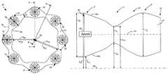
- FIG. 2is an end view of the input end of an annular combustor including a three-dimensionally contoured combustor liner.
- FIG. 3Ais a cross-sectional view of a first embodiment of the combustor of FIG. 2 from line A-A.
- FIG. 3Bis a cross-sectional view of a first embodiment of the combustor of FIG. 2 from line B-B.
- FIG. 4Ais a cross-sectional view of a second embodiment of the combustor of FIG. 2 from line A-A.
- FIG. 4Bis a cross-sectional view of a second embodiment of the combustor of FIG. 2 from line B-B.
- FIG. 1is a cross-sectional view of gas turbine engine 10 , which includes turbofan 12 , compressor section 14 , combustion section 16 and turbine section 18 .
- Compressor section 14includes low-pressure compressor 20 and high-pressure compressor 22 . Air is taken in through fan 12 as fan 12 spins. A portion of the inlet air is directed to compressor section 14 where it is compressed by a series of rotating blades and vanes. The compressed air is mixed with fuel, and is then inserted into combustor section 16 through nozzles and ignited. The combustion exhaust is directed to turbine section 18 . Blades and vanes in turbine section 18 extract energy from the combustion exhaust to turn shaft 24 and provide power output for engine 10 .
- the portion of inlet air that is taken in through fan 12 and not directed through compressor section 14is bypass air. Bypass air is directed through bypass duct 26 by guide vanes 28 . Some of the bypass air flows through opening 29 to cool combustor section 16 , high pressure compressor 22 and turbine section 18 .
- FIG. 2shows an end view of an annular combustor 30 at the input end (compressor end), which includes nozzles 32 , combustor liner inner wall 34 , combustor liner outer wall 36 and combustion chamber 37 .
- Engine center line 38 and dimensions R IE , R OE , R IC , R OC , D E and D Care also shown.
- Nozzles 32generally are evenly spaced between liner inner wall 34 and liner outer wall 36 .
- Liner inner wall 34 and liner outer wall 36can be made with cobalt or a nickel alloy and may include a thermal barrier coating.
- Liner inner and outer walls 34 , 36include three-dimensional contours around the circumference of the inner and outer walls 34 , 36 and three-dimensional contours axially through length of the combustion chamber 37 from the input to the output.
- the three-dimensional contoursare generally in a wavelike pattern forming alternating regions of constriction and expansion in combustion chamber 37 .
- the contours around the circumference at the input end of combustor 30can be seen from the view shown in FIG. 2 .
- the contours around the circumference of liner walls 34 , 36form regions of expansion at nozzles 32 and regions of constriction between nozzles 32 .
- R IEis the distance from engine center line 38 to liner inner wall 34 at a region of expansion.
- R OEis the distance from engine center line to liner outer wall 36 at a region of expansion.
- R ICis the distance from engine center line 38 to liner inner wall 34 at a region of constriction.
- R OCis the distance from engine center line to liner outer wall 36 at a region of constriction.
- D Eis the distance between liner inner wall 34 and liner outer wall 36 at a region of expansion (R OE -R IE ).
- D Cis the distance between liner inner wall 34 and liner outer wall 36 at a region of constriction (R OC -R IC ).
- liner inner wall 34 and liner outer wall 36generally mirror each other, and can be of the size that D C (the distance from liner inner wall 34 to liner outer wall 36 at a region of constriction) is about 1 ⁇ 3 to about 3 ⁇ 5 of D E (the distance from liner inner wall 34 to liner outer wall 36 at a region of expansion), but may be more or less depending on the needs of the particular combustor.
- Each nozzle 32distributes compressed air and fuel into combustor 30 , between liner inner wall 34 and liner outer wall 36 .
- the air and fuel distributedis a mixture set for flame holding to promote combustion within the combustion chamber 37 . This distribution by nozzles 32 results in very intense heat at each discrete nozzle 32 .
- HPThigh pressure turbine
- Circumferential variation in the temperature entering turbine 18leads to variation in distress observed by static hardware in turbine 18 .
- Advanced distress of turbine hardware at a single circumferential locationcan limit service life of the engine, or time between overhauls.
- a circumferentially prescribed or uniform temperature profileis desirable.
- Mixing of the air and fuel axially through the length of combustor 30 from input to outputcan promote a more uniform distribution of temperature (as well as pressure and species) at the output of combustor 30 . This uniform distribution of temperature going into the turbine helps to ensure that the progression of distress on turbine hardware is not dependent on circumferential location.
- the current inventioncontrols the mixing by adding three-dimensional contours circumferentially and axially through the length of combustor 30 liner inner wall 34 and liner outer wall 36 to form alternating regions of constriction and expansion within combustion chamber 37 .
- mixingwas often done by adding dilution holes or jets to combustor liner walls 34 , 36 .
- Dilution holesare holes in liner walls which allow cooler air into the combustor to promote mixing. Dilution jets propel air into the combustor at high velocity to promote mixing in the combustor.
- the current inventionfurther promotes mixing and controls the flow in combustor 30 by adding three-dimensional contours circumferentially and axially through the length of combustor 30 liner inner wall 34 and liner outer wall 36 to form alternating regions of constriction and expansion within combustion chamber 37 .
- FIG. 3Ais a cross-sectional view of a first embodiment of the combustor of FIG. 2 above engine center line 38 from line A-A (at nozzle 32 ) of FIG. 2 .
- FIG. 3Aincludes nozzle 32 , three-dimensionally contoured liner inner wall 34 a, three-dimensionally contoured liner outer wall 36 a, combustion chamber 37 , input end 40 , output end 42 , nozzle center line of flow 44 , regions of expansion E and a region of constriction C.
- R IE(from engine centerline 38 to liner inner wall 34 a at a region of expansion), R OE (from engine centerline 38 to liner outer wall 36 a at a region of expansion), R IC (from engine centerline 38 to liner inner wall 34 a at a region of constriction), R OC (from engine centerline 38 to liner outer wall 36 a at a region of constriction), D E (between liner inner wall 34 a and liner outer wall 36 a at a region of expansion, R OE -R IE ) and D C (between liner inner wall 34 a and liner outer wall 36 a at a region of constriction, R OC -R IC ) for regions of expansion and constriction are also shown.
- liner inner wall 34 a and outer wall 36 ainclude three-dimensional contours both circumferentially and axially through the length of combustor 30 from input 40 to output 42 to form alternating regions of constriction C and expansion E. These alternating regions of constriction C and expansion E force combustion gases to move circumferentially as well as axially after being injected into combustion chamber 37 .
- Contoured liner inner wall 34 a and liner outer wall 36 aillustrate contours axially through the length of combustor liner at a cross-section where a nozzle 32 is located.
- Liner inner wall 34 a and liner outer wall 36 aform a region of expansion E at input 40 .
- liner inner wall 34 a and liner outer wall 36 aform a region of constriction C, and then another region of expansion E (in a wavelike pattern).
- inner liner wall 34 a and outer liner wall 36 agenerally mirror each other, and each liner wall ( 34 a, 36 a ) can come toward the other about 1 ⁇ 6 to about 1/10 of the distance of D E (the distance between liner inner wall 34 a and liner outer wall 36 a at an expansion region).
- D Ethe distance between liner inner wall 34 a and liner outer wall 36 a at an expansion region.
- FIG. 3Bis a cross-sectional view of a first embodiment of the combustor of FIG. 2 above engine center line 38 from line B-B (between nozzles) of FIG. 2 .
- FIG. 3Bincludes three-dimensionally contoured liner inner wall 34 b, three-dimensionally contoured liner outer wall 36 b, combustion chamber 37 , input end 40 , output end 42 , and regions of constriction C and a region of expansion E.
- FIG. 3Bincludes three-dimensionally contoured liner inner wall 34 b, three-dimensionally contoured liner outer wall 36 b, combustion chamber 37 , input end 40 , output end 42 , and regions of constriction C and a region of expansion E.
- 3Bfurther includes dimensions R 3 (from engine centerline 38 to liner inner wall 34 b at a region of expansion), R OE (from engine centerline 38 to liner outer wall 36 b at a region of expansion), R IC (from engine centerline 38 to liner inner wall 34 b at a region of constriction), R OC (from engine centerline 38 to liner outer wall 36 b at a region of constriction), D E (between liner inner wall 34 b and liner outer wall 36 b at a region of expansion, R OE -R IE ) and D C (between liner inner wall 34 b and liner outer wall 36 b at a region of constriction, R OC -R IC ).
- Contoured liner inner wall 34 b and liner outer wall 36 billustrate contours axially through the length of combustor liner at a cross-section between where nozzles 32 are located.
- FIG. 3Bcross-sections between nozzles 32 at input 40 of combustion chamber 37 start with a region of constriction C, followed by a region of expansion E, and then another region of constriction C.
- FIG. 3Bcross-sections between nozzles 32 at input 40 of combustion chamber 37 start with a region of constriction C, followed by a region of expansion E, and then another region of constriction C.
- inner liner wall 34 b and outer liner wall 36 bgenerally mirror each other, and each liner wall ( 34 b, 36 b ) can be come toward the other about 1 ⁇ 6 to about 1/10 of the distance of D E (the distance between liner inner wall 34 b and liner outer wall 36 b at an expansion region E).
- D Ethe distance between liner inner wall 34 b and liner outer wall 36 b at an expansion region E
- D Cthe distance between liner inner wall 34 b and liner outer wall 36 b at a constriction region C
- the zones of constriction and expansion in FIG. 3Balso work to force a circumferential flow of the gases within combustion chamber 37 , thereby promoting mixing and a more even distribution of temperature, pressure and species in combustor 30 as gases move from input 40 to output 42 .
- FIG. 3A and in FIG. 3Bare circumferentially next to each other and work together to promote mixing.
- FIGS. 3A-3Bwhen the inner and outer liner walls of FIG. 3A form a region of constriction, the inner and outer liner walls of FIG. 3B form a region of expansion (and vice versa).
- FIG. 3A liner walls 34 a, 36 aform a region of expansion
- FIG. 3B liner walls 34 b, 36 bform a region of constriction.
- Contoured liner walls 34 , 36can also include dilution holes and/or dilution jets (discussed in relation to FIG. 2 ) to further promote mixing in and aid in cooling combustor 30 .
- contours on liner inner walls 34 and liner outer walls 36are shown for example purposes only and may be varied according to combustor needs.
- the scale of contoursis proportional to the combustor velocity, the velocity at which the fuel and air mixture is distributed from nozzles 32 .
- contours which form regions of constrictionwould have to be larger to promote mixing and control the flow direction (for example, D C can be about 1 ⁇ 3 of D E ) than if nozzle 32 has a higher velocity.
- D Ccan be about 1 ⁇ 3 of D E
- contourscould be smaller (for example, D C can be about 3 ⁇ 5 of D E ).
- FIG. 4Aillustrates a cross-section of a second embodiment of the combustor of FIG. 2 from line A-A of FIG. 2 , having a three-dimensionally contoured liner, with the combustor having a variation in volume from input 40 to output 42 , specifically a decrease in volume.
- Combustor 30includes nozzle 32 ; three-dimensionally contoured liner inner wall 34 ′; three-dimensionally contoured liner outer wall 36 ′; combustion chamber 37 ; input end 40 ; output end 42 ; nozzle center line of flow 44 ; axial zones F, G and H; and dimensions D FE (from inner liner wall 34 ′ to outer liner wall 36 ′ at expansion region E in zone F), D GC (from inner liner wall 34 ′ to outer liner wall 36 ′ at constriction region C in zone G), and D HE (from inner liner wall 34 ′ to outer liner wall 36 ′ at expansion region E in zone H).
- FIG. 4Billustrates a cross-section of a second embodiment of the combustor of FIG. 2 from line B-B (between nozzles) of FIG. 2 .
- FIG. 4Bincludes three-dimensionally contoured liner inner wall 34 ′; three-dimensionally contoured liner outer wall 36 ′; combustion chamber 37 ; input end 40 ; output end 42 ; axial zones F, G, and H; and distance measurements D FC (from inner liner wall 34 ′ to outer liner wall 36 ′ at constriction region C in zone F), D GE (from inner liner wall 34 ′ to outer liner wall 36 ′ at expansion region E in zone G), and D HC (from inner liner wall 34 ′ to outer liner wall 36 ′ at constriction region C in zone H).
- D FCfrom inner liner wall 34 ′ to outer liner wall 36 ′ at constriction region C in zone F
- D GEfrom inner liner wall 34 ′ to outer liner wall 36 ′ at expansion region E in zone G
- Combustor 30contoured liner inner walls 34 ′ and contoured liner outer walls 36 ′ work much the same way as discussed in relation to FIGS. 3A-3B , moving flow circumferentially and mixing combustion gases from input 40 to output 42 .
- the combustion chamber 37experiences a decrease in volume from input 40 to output 42 (as shown through cross-sections F, G, H losing area from input 40 to output 42 ). Therefore, the distance measurements between liner inner wall 34 ′ and liner outer wall 36 ′ for areas of expansion E are largest in zone F (D FE in FIG. 4A ), smaller in zone G (D GE in FIG. 4B ), and smallest in zone H (D HE in FIG. 4A ).
- the scale of contours to form regions of constriction Cis approximately inversely proportional to the velocity of the combustion gases. Smaller contours (meaning the distance D C between inner liner wall 34 ′ and outer liner wall 36 ′ is larger in regions of constriction C) can promote mixing when velocity is higher, whereas larger contours (meaning the distance D C between inner liner wall 34 ′ and outer liner wall 36 ′ is smaller in regions of constriction C) are necessary to promote the same levels of mixing when velocity is lower.
- the contours forming constriction regions C on liner inner wall 34 ′ and liner outer wall 36 ′can decrease while still promoting the same levels of mixing.
- the contoursmay diminish to zero or to small values as that might be needed for controlling the flow into the HPT vane (making dimensions D E and D C about equal).
- the current inventionadds three-dimensional contouring of inner and outer liner walls in a combustor to form alternating regions of constriction and expansion both circumferentially and axially to better control flow coming out of the combustor into the turbine.
- By controlling flow to promote mixingan even or prescribed distribution of temperature, pressure and species at the output of the combustor can be achieved. This can prolong engine life by preventing the advanced distress of turbine hardware due to hot spots flowing out of the combustor and into the turbine. This mixing can also promote more efficient combustion in the combustor.
- the three-dimensional contoursmay allow for the elimination of some or all dilution holes and/or dilution jets in the combustor liner (previously used to promote mixing).
- the three-dimensionally contoured linercould be used in situations where an even distribution is not desired.
- the three-dimensional wavelike contours forming regions of constriction and expansioncan be placed throughout the combustor liner inner wall and liner outer wall to control flow and/or promote mixing in any way desired. While this invention has been discussed mainly in reference to liner inner and liner outer walls each having three-dimensional contours, controlling of the flow and/or mixing can also be done by having three-dimensional contours only on liner inner wall or liner outer wall.
Landscapes
- Engineering & Computer Science (AREA)
- Chemical & Material Sciences (AREA)
- Combustion & Propulsion (AREA)
- Mechanical Engineering (AREA)
- General Engineering & Computer Science (AREA)
Abstract
Description
Claims (15)
Priority Applications (1)
| Application Number | Priority Date | Filing Date | Title |
|---|---|---|---|
| US15/195,383US10514171B2 (en) | 2010-02-22 | 2016-06-28 | 3D non-axisymmetric combustor liner |
Applications Claiming Priority (3)
| Application Number | Priority Date | Filing Date | Title |
|---|---|---|---|
| US12/709,951US8707708B2 (en) | 2010-02-22 | 2010-02-22 | 3D non-axisymmetric combustor liner |
| US14/202,969US20140190175A1 (en) | 2010-02-22 | 2014-03-10 | 3d non-axisymmetric combustor liner |
| US15/195,383US10514171B2 (en) | 2010-02-22 | 2016-06-28 | 3D non-axisymmetric combustor liner |
Related Parent Applications (1)
| Application Number | Title | Priority Date | Filing Date |
|---|---|---|---|
| US14/202,969ContinuationUS20140190175A1 (en) | 2010-02-22 | 2014-03-10 | 3d non-axisymmetric combustor liner |
Publications (2)
| Publication Number | Publication Date |
|---|---|
| US20160305664A1 US20160305664A1 (en) | 2016-10-20 |
| US10514171B2true US10514171B2 (en) | 2019-12-24 |
Family
ID=44080136
Family Applications (3)
| Application Number | Title | Priority Date | Filing Date |
|---|---|---|---|
| US12/709,951Active2033-03-01US8707708B2 (en) | 2010-02-22 | 2010-02-22 | 3D non-axisymmetric combustor liner |
| US14/202,969AbandonedUS20140190175A1 (en) | 2010-02-22 | 2014-03-10 | 3d non-axisymmetric combustor liner |
| US15/195,383Active2032-04-24US10514171B2 (en) | 2010-02-22 | 2016-06-28 | 3D non-axisymmetric combustor liner |
Family Applications Before (2)
| Application Number | Title | Priority Date | Filing Date |
|---|---|---|---|
| US12/709,951Active2033-03-01US8707708B2 (en) | 2010-02-22 | 2010-02-22 | 3D non-axisymmetric combustor liner |
| US14/202,969AbandonedUS20140190175A1 (en) | 2010-02-22 | 2014-03-10 | 3d non-axisymmetric combustor liner |
Country Status (2)
| Country | Link |
|---|---|
| US (3) | US8707708B2 (en) |
| EP (1) | EP2362138B1 (en) |
Cited By (3)
| Publication number | Priority date | Publication date | Assignee | Title |
|---|---|---|---|---|
| US11747019B1 (en)* | 2022-09-02 | 2023-09-05 | General Electric Company | Aerodynamic combustor liner design for emissions reductions |
| US11788724B1 (en)* | 2022-09-02 | 2023-10-17 | General Electric Company | Acoustic damper for combustor |
| US11994291B2 (en) | 2022-07-21 | 2024-05-28 | General Electric Company | Performance factor for a combustion liner |
Families Citing this family (15)
| Publication number | Priority date | Publication date | Assignee | Title |
|---|---|---|---|---|
| US8707708B2 (en) | 2010-02-22 | 2014-04-29 | United Technologies Corporation | 3D non-axisymmetric combustor liner |
| US9550230B2 (en) | 2011-09-16 | 2017-01-24 | United Technologies Corporation | Mold for casting a workpiece that includes one or more casting pins |
| CN103917826B (en)* | 2011-11-17 | 2016-08-24 | 通用电气公司 | Turbomachine combustor assembly and the method for operation turbine |
| US10655855B2 (en) | 2013-08-30 | 2020-05-19 | Raytheon Technologies Corporation | Gas turbine engine wall assembly with support shell contour regions |
| EP3077729B1 (en)* | 2013-12-06 | 2020-07-15 | United Technologies Corporation | Gas turbine engine wall assembly interface |
| US9845956B2 (en)* | 2014-04-09 | 2017-12-19 | General Electric Company | System and method for control of combustion dynamics in combustion system |
| CN106338084B (en)* | 2016-11-21 | 2018-11-20 | 深圳智慧能源技术有限公司 | Gas-turbine combustion chamber |
| EP3361159B1 (en) | 2017-02-13 | 2019-09-18 | Ansaldo Energia Switzerland AG | Method for manufacturing a burner assembly for a gas turbine combustor and burner assembly for a gas turbine combustor |
| US20180299126A1 (en)* | 2017-04-18 | 2018-10-18 | United Technologies Corporation | Combustor liner panel end rail |
| US20180306113A1 (en)* | 2017-04-19 | 2018-10-25 | United Technologies Corporation | Combustor liner panel end rail matching heat transfer features |
| US20200318549A1 (en)* | 2019-04-04 | 2020-10-08 | United Technologies Corporation | Non-axisymmetric combustor for improved durability |
| US11940151B2 (en)* | 2022-01-12 | 2024-03-26 | General Electric Company | Combustor with baffle |
| GB202307701D0 (en) | 2023-05-23 | 2023-07-05 | Rolls Royce Plc | An improved combustor apparatus |
| GB202307700D0 (en) | 2023-05-23 | 2023-07-05 | Rolls Royce Plc | An improved combustor apparatus |
| GB202307702D0 (en)* | 2023-05-23 | 2023-07-05 | Rolls Royce Plc | An improved combustor apparatus |
Citations (28)
| Publication number | Priority date | Publication date | Assignee | Title |
|---|---|---|---|---|
| US2540991A (en) | 1942-03-06 | 1951-02-06 | Lockheed Aircraft Corp | Gas reaction aircraft power plant |
| US2610467A (en) | 1946-04-03 | 1952-09-16 | Westinghouse Electric Corp | Combustion chamber having telescoping walls and corrugated spacers |
| US2641105A (en) | 1948-10-11 | 1953-06-09 | Marquardt Aircraft Company | Temperature control system having means to measure turbine inlet temperature indirectly |
| US2704440A (en) | 1952-01-17 | 1955-03-22 | Power Jets Res & Dev Ltd | Gas turbine plant |
| US2821066A (en) | 1953-03-05 | 1958-01-28 | Lucas Industries Ltd | Air-jacketed annular combustion chamber for a jet-propulsion engine, gas turbine or the like |
| US2833115A (en) | 1953-03-05 | 1958-05-06 | Lucas Industries Ltd | Air-jacketed annular combustion chambers for jet-propulsion engines, gas turbines or the like |
| US2913873A (en) | 1955-01-10 | 1959-11-24 | Rolls Royce | Gas turbine combustion equipment construction |
| US3082603A (en) | 1955-10-28 | 1963-03-26 | Snecma | Combustion chamber with primary and secondary air flows |
| US3138930A (en) | 1961-09-26 | 1964-06-30 | Gen Electric | Combustion chamber liner construction |
| US4158949A (en) | 1977-11-25 | 1979-06-26 | General Motors Corporation | Segmented annular combustor |
| US4265085A (en) | 1979-05-30 | 1981-05-05 | United Technologies Corporation | Radially staged low emission can-annular combustor |
| US4265615A (en) | 1978-12-11 | 1981-05-05 | United Technologies Corporation | Fuel injection system for low emission burners |
| US4422300A (en) | 1981-12-14 | 1983-12-27 | United Technologies Corporation | Prestressed combustor liner for gas turbine engine |
| US4996838A (en) | 1988-10-27 | 1991-03-05 | Sol-3 Resources, Inc. | Annular vortex slinger combustor |
| US5207064A (en) | 1990-11-21 | 1993-05-04 | General Electric Company | Staged, mixed combustor assembly having low emissions |
| US5279127A (en) | 1990-12-21 | 1994-01-18 | General Electric Company | Multi-hole film cooled combustor liner with slotted film starter |
| US5329773A (en) | 1989-08-31 | 1994-07-19 | Alliedsignal Inc. | Turbine combustor cooling system |
| US5481867A (en) | 1988-05-31 | 1996-01-09 | United Technologies Corporation | Combustor |
| US6021570A (en) | 1997-11-20 | 2000-02-08 | Caterpillar Inc. | Annular one piece combustor liner |
| US6250082B1 (en) | 1999-12-03 | 2001-06-26 | General Electric Company | Combustor rear facing step hot side contour method and apparatus |
| US6484505B1 (en) | 2000-02-25 | 2002-11-26 | General Electric Company | Combustor liner cooling thimbles and related method |
| US6553767B2 (en) | 2001-06-11 | 2003-04-29 | General Electric Company | Gas turbine combustor liner with asymmetric dilution holes machined from a single piece form |
| US6655147B2 (en) | 2002-04-10 | 2003-12-02 | General Electric Company | Annular one-piece corrugated liner for combustor of a gas turbine engine |
| US6701714B2 (en) | 2001-12-05 | 2004-03-09 | United Technologies Corporation | Gas turbine combustor |
| US7010921B2 (en) | 2004-06-01 | 2006-03-14 | General Electric Company | Method and apparatus for cooling combustor liner and transition piece of a gas turbine |
| US7089742B2 (en) | 2000-02-29 | 2006-08-15 | Rolls-Royce Plc | Wall elements for gas turbine engine combustors |
| DE102008026463A1 (en) | 2008-06-03 | 2009-12-10 | E.On Ruhrgas Ag | Combustion device for gas turbine system in natural gas pipeline network, has cooling arrays arranged over circumference of central body, distributed at preset position on body, and provided adjacent to primary fuel injectors |
| US8707708B2 (en) | 2010-02-22 | 2014-04-29 | United Technologies Corporation | 3D non-axisymmetric combustor liner |
- 2010
- 2010-02-22USUS12/709,951patent/US8707708B2/enactiveActive
- 2011
- 2011-02-18EPEP11250192.9Apatent/EP2362138B1/enactiveActive
- 2014
- 2014-03-10USUS14/202,969patent/US20140190175A1/ennot_activeAbandoned
- 2016
- 2016-06-28USUS15/195,383patent/US10514171B2/enactiveActive
Patent Citations (28)
| Publication number | Priority date | Publication date | Assignee | Title |
|---|---|---|---|---|
| US2540991A (en) | 1942-03-06 | 1951-02-06 | Lockheed Aircraft Corp | Gas reaction aircraft power plant |
| US2610467A (en) | 1946-04-03 | 1952-09-16 | Westinghouse Electric Corp | Combustion chamber having telescoping walls and corrugated spacers |
| US2641105A (en) | 1948-10-11 | 1953-06-09 | Marquardt Aircraft Company | Temperature control system having means to measure turbine inlet temperature indirectly |
| US2704440A (en) | 1952-01-17 | 1955-03-22 | Power Jets Res & Dev Ltd | Gas turbine plant |
| US2821066A (en) | 1953-03-05 | 1958-01-28 | Lucas Industries Ltd | Air-jacketed annular combustion chamber for a jet-propulsion engine, gas turbine or the like |
| US2833115A (en) | 1953-03-05 | 1958-05-06 | Lucas Industries Ltd | Air-jacketed annular combustion chambers for jet-propulsion engines, gas turbines or the like |
| US2913873A (en) | 1955-01-10 | 1959-11-24 | Rolls Royce | Gas turbine combustion equipment construction |
| US3082603A (en) | 1955-10-28 | 1963-03-26 | Snecma | Combustion chamber with primary and secondary air flows |
| US3138930A (en) | 1961-09-26 | 1964-06-30 | Gen Electric | Combustion chamber liner construction |
| US4158949A (en) | 1977-11-25 | 1979-06-26 | General Motors Corporation | Segmented annular combustor |
| US4265615A (en) | 1978-12-11 | 1981-05-05 | United Technologies Corporation | Fuel injection system for low emission burners |
| US4265085A (en) | 1979-05-30 | 1981-05-05 | United Technologies Corporation | Radially staged low emission can-annular combustor |
| US4422300A (en) | 1981-12-14 | 1983-12-27 | United Technologies Corporation | Prestressed combustor liner for gas turbine engine |
| US5481867A (en) | 1988-05-31 | 1996-01-09 | United Technologies Corporation | Combustor |
| US4996838A (en) | 1988-10-27 | 1991-03-05 | Sol-3 Resources, Inc. | Annular vortex slinger combustor |
| US5329773A (en) | 1989-08-31 | 1994-07-19 | Alliedsignal Inc. | Turbine combustor cooling system |
| US5207064A (en) | 1990-11-21 | 1993-05-04 | General Electric Company | Staged, mixed combustor assembly having low emissions |
| US5279127A (en) | 1990-12-21 | 1994-01-18 | General Electric Company | Multi-hole film cooled combustor liner with slotted film starter |
| US6021570A (en) | 1997-11-20 | 2000-02-08 | Caterpillar Inc. | Annular one piece combustor liner |
| US6250082B1 (en) | 1999-12-03 | 2001-06-26 | General Electric Company | Combustor rear facing step hot side contour method and apparatus |
| US6484505B1 (en) | 2000-02-25 | 2002-11-26 | General Electric Company | Combustor liner cooling thimbles and related method |
| US7089742B2 (en) | 2000-02-29 | 2006-08-15 | Rolls-Royce Plc | Wall elements for gas turbine engine combustors |
| US6553767B2 (en) | 2001-06-11 | 2003-04-29 | General Electric Company | Gas turbine combustor liner with asymmetric dilution holes machined from a single piece form |
| US6701714B2 (en) | 2001-12-05 | 2004-03-09 | United Technologies Corporation | Gas turbine combustor |
| US6655147B2 (en) | 2002-04-10 | 2003-12-02 | General Electric Company | Annular one-piece corrugated liner for combustor of a gas turbine engine |
| US7010921B2 (en) | 2004-06-01 | 2006-03-14 | General Electric Company | Method and apparatus for cooling combustor liner and transition piece of a gas turbine |
| DE102008026463A1 (en) | 2008-06-03 | 2009-12-10 | E.On Ruhrgas Ag | Combustion device for gas turbine system in natural gas pipeline network, has cooling arrays arranged over circumference of central body, distributed at preset position on body, and provided adjacent to primary fuel injectors |
| US8707708B2 (en) | 2010-02-22 | 2014-04-29 | United Technologies Corporation | 3D non-axisymmetric combustor liner |
Non-Patent Citations (1)
| Title |
|---|
| Extended European Search Report from EP Application Serial No. 1125012.9; dated Jun. 27, 2011, 6 pages. |
Cited By (3)
| Publication number | Priority date | Publication date | Assignee | Title |
|---|---|---|---|---|
| US11994291B2 (en) | 2022-07-21 | 2024-05-28 | General Electric Company | Performance factor for a combustion liner |
| US11747019B1 (en)* | 2022-09-02 | 2023-09-05 | General Electric Company | Aerodynamic combustor liner design for emissions reductions |
| US11788724B1 (en)* | 2022-09-02 | 2023-10-17 | General Electric Company | Acoustic damper for combustor |
Also Published As
| Publication number | Publication date |
|---|---|
| EP2362138A1 (en) | 2011-08-31 |
| US20110203286A1 (en) | 2011-08-25 |
| US8707708B2 (en) | 2014-04-29 |
| US20140190175A1 (en) | 2014-07-10 |
| US20160305664A1 (en) | 2016-10-20 |
| EP2362138B1 (en) | 2016-06-29 |
Similar Documents
| Publication | Publication Date | Title |
|---|---|---|
| US10514171B2 (en) | 3D non-axisymmetric combustor liner | |
| JP5842311B2 (en) | Tangential combustor with vaneless turbine for use in gas turbine engine | |
| US9759426B2 (en) | Combustor nozzles in gas turbine engines | |
| US7624577B2 (en) | Gas turbine engine combustor with improved cooling | |
| EP2481983B1 (en) | Turbulated Aft-End liner assembly and cooling method for gas turbine combustor | |
| US7104067B2 (en) | Combustor liner with inverted turbulators | |
| EP2971970B1 (en) | Counter swirl doublet combustor | |
| CN1114732A (en) | Method for cooling self-burning combustion chamber | |
| KR102720223B1 (en) | Dual fuel lance with cooling microchannels | |
| US20090145132A1 (en) | Methods and system for reducing pressure losses in gas turbine engines | |
| US20120304654A1 (en) | Combustion liner having turbulators | |
| EP2375160A2 (en) | Angled seal cooling system | |
| KR20150020135A (en) | Burner arrangement and method for operating a burner arrangement | |
| US20150159878A1 (en) | Combustion system for a gas turbine engine | |
| CN103930723A (en) | Tangential annular combustor with premixed fuel and air for use on a gas turbine | |
| JP6012733B2 (en) | Combustion chamber wall | |
| EP3032174B1 (en) | Counter-swirl doublet combustor with plunged holes | |
| CN111219735B (en) | A burner lance; method for manufacturing the burner lance and gas turbine assembly |
Legal Events
| Date | Code | Title | Description |
|---|---|---|---|
| AS | Assignment | Owner name:UNITED TECHNOLOGIES CORPORATION, CONNECTICUT Free format text:ASSIGNMENT OF ASSIGNORS INTEREST;ASSIGNORS:WAGNER, JOEL H.;LUTJEN, PAUL M.;SIGNING DATES FROM 20100218 TO 20100222;REEL/FRAME:039031/0827 | |
| STPP | Information on status: patent application and granting procedure in general | Free format text:DOCKETED NEW CASE - READY FOR EXAMINATION | |
| STPP | Information on status: patent application and granting procedure in general | Free format text:NON FINAL ACTION MAILED | |
| STPP | Information on status: patent application and granting procedure in general | Free format text:RESPONSE TO NON-FINAL OFFICE ACTION ENTERED AND FORWARDED TO EXAMINER | |
| STPP | Information on status: patent application and granting procedure in general | Free format text:NOTICE OF ALLOWANCE MAILED -- APPLICATION RECEIVED IN OFFICE OF PUBLICATIONS | |
| STPP | Information on status: patent application and granting procedure in general | Free format text:PUBLICATIONS -- ISSUE FEE PAYMENT VERIFIED | |
| STCF | Information on status: patent grant | Free format text:PATENTED CASE | |
| AS | Assignment | Owner name:RAYTHEON TECHNOLOGIES CORPORATION, MASSACHUSETTS Free format text:CHANGE OF NAME;ASSIGNOR:UNITED TECHNOLOGIES CORPORATION;REEL/FRAME:054062/0001 Effective date:20200403 | |
| AS | Assignment | Owner name:RAYTHEON TECHNOLOGIES CORPORATION, CONNECTICUT Free format text:CORRECTIVE ASSIGNMENT TO CORRECT THE AND REMOVE PATENT APPLICATION NUMBER 11886281 AND ADD PATENT APPLICATION NUMBER 14846874. TO CORRECT THE RECEIVING PARTY ADDRESS PREVIOUSLY RECORDED AT REEL: 054062 FRAME: 0001. ASSIGNOR(S) HEREBY CONFIRMS THE CHANGE OF ADDRESS;ASSIGNOR:UNITED TECHNOLOGIES CORPORATION;REEL/FRAME:055659/0001 Effective date:20200403 | |
| MAFP | Maintenance fee payment | Free format text:PAYMENT OF MAINTENANCE FEE, 4TH YEAR, LARGE ENTITY (ORIGINAL EVENT CODE: M1551); ENTITY STATUS OF PATENT OWNER: LARGE ENTITY Year of fee payment:4 | |
| AS | Assignment | Owner name:RTX CORPORATION, CONNECTICUT Free format text:CHANGE OF NAME;ASSIGNOR:RAYTHEON TECHNOLOGIES CORPORATION;REEL/FRAME:064714/0001 Effective date:20230714 |