US10512511B2 - Multi-function mounting interface for an image-guided robotic system and quick release interventional toolset - Google Patents
Multi-function mounting interface for an image-guided robotic system and quick release interventional toolsetDownload PDFInfo
- Publication number
- US10512511B2 US10512511B2US14/906,651US201414906651AUS10512511B2US 10512511 B2US10512511 B2US 10512511B2US 201414906651 AUS201414906651 AUS 201414906651AUS 10512511 B2US10512511 B2US 10512511B2
- Authority
- US
- United States
- Prior art keywords
- cannula
- track
- tool
- carriage
- medical instrument
- Prior art date
- Legal status (The legal status is an assumption and is not a legal conclusion. Google has not performed a legal analysis and makes no representation as to the accuracy of the status listed.)
- Active, expires
Links
Images


Classifications
- A—HUMAN NECESSITIES
- A61—MEDICAL OR VETERINARY SCIENCE; HYGIENE
- A61B—DIAGNOSIS; SURGERY; IDENTIFICATION
- A61B34/00—Computer-aided surgery; Manipulators or robots specially adapted for use in surgery
- A61B34/30—Surgical robots
- A—HUMAN NECESSITIES
- A61—MEDICAL OR VETERINARY SCIENCE; HYGIENE
- A61B—DIAGNOSIS; SURGERY; IDENTIFICATION
- A61B34/00—Computer-aided surgery; Manipulators or robots specially adapted for use in surgery
- A61B34/70—Manipulators specially adapted for use in surgery
- A—HUMAN NECESSITIES
- A61—MEDICAL OR VETERINARY SCIENCE; HYGIENE
- A61B—DIAGNOSIS; SURGERY; IDENTIFICATION
- A61B10/00—Instruments for taking body samples for diagnostic purposes; Other methods or instruments for diagnosis, e.g. for vaccination diagnosis, sex determination or ovulation-period determination; Throat striking implements
- A61B10/02—Instruments for taking cell samples or for biopsy
- A61B10/0233—Pointed or sharp biopsy instruments
- A61B10/0283—Pointed or sharp biopsy instruments with vacuum aspiration, e.g. caused by retractable plunger or by connected syringe
- A—HUMAN NECESSITIES
- A61—MEDICAL OR VETERINARY SCIENCE; HYGIENE
- A61B—DIAGNOSIS; SURGERY; IDENTIFICATION
- A61B17/00—Surgical instruments, devices or methods
- A61B2017/00477—Coupling
Definitions
- This inventionrelates to surgical robotics, and in particular the control of medical instruments which have an insertion action, such as a biopsy needle or ablation tool.
- Cancer diagnosis and treatmentcan require the medical practitioner to be able to pin point a suspicious lesion within the patient.
- the next step in a typical treatment processcan include a biopsy procedure to identify the pathology, which can be performed in the operating room, with the patient under general anesthetic.
- biopsy procedurescan include the implementation of core needle biopsy procedures using minimally invasive core needle extraction methods.
- Difficultiescan arise in performing a conventional procedure.
- MRImagnetic resonance imaging
- the patientmay have to be shuttled in and out of the magnet several times before a biopsy is actually performed.
- the contrast agentcould have already lost some of its effect and image quality could suffer. This process itself may be time consuming and cumbersome, especially in a time-sensitive environment.
- contrast laden blood from a hematoma as well as an air pocket at the biopsy sitecan make it difficult to subsequently verify that the correct site identified from the imaging system was biopsied, or to rapidly confirm that the sample obtained has a suspect morphology.
- This practicecould also require removal of a relatively large volume of tissue, with a fraction of that assumed to be from the lesion.
- a tool mount adaptorfor interfacing a medical instrument with a medical insertion device, the tool mount adaptor comprising a collar for holding a medical instrument, wherein the tool mount adaptor is releasably attachable to the medical insertion device.
- the collarcomprises a first piece and a second piece, wherein the first piece and the second piece are releasably connectable to form the collar.
- a first end of the first pieceis releasably connectable with a first end of the second piece and a second end of the first piece is releasably connectable with a second end of the second piece to form the collar.
- the tool mount adaptorfurther comprises a locking mechanism, wherein the locking mechanism is adapted to restrict separation of the first piece and the second piece when in a locked mode and allow separation of the first piece and the second piece when in an unlocked mode.
- the tool mount adaptorfurther comprises a locking mechanism, wherein: when in a locked mode, the locking mechanism restricts separation of the first piece and the second piece and restricts detachment of the tool mount adaptor from the medical insertion device; and when in an unlocked mode, the locking mechanism allows separation of the first piece and the second piece and allows detachment of the tool mount adaptor from the medical insertion device.
- the tool mount adaptoris attached to the medical insertion device by way of an end effector interface and the tool mount adaptor further comprises a locking mechanism, wherein: when in a locked mode, the locking mechanism restricts separation of the first piece and the second piece and restricts detachment of the tool mount adaptor from the end effector interface; and when in an unlocked mode, the locking mechanism allows separation of the first piece and the second piece and allows detachment of the tool mount adaptor from the end effector interface.
- the medical insertion devicecomprises lateral receiving members and the collar comprises engaging members adapted to engage the receiving members.
- the receiving membersdefine apertures and the engaging members comprise a nub complementary to the apertures.
- the tool mount adaptoris attached to the medical insertion device by way of an end effector interface and the end effector interface comprises lateral receiving members and the collar comprises engaging members adapted to engage the receiving members.
- the receiving membersdefine apertures and the engaging members comprise a nub complementary to the apertures.
- the tool mount adaptormay further comprise a latch to secure the medical instrument to the collar.
- the tool mount adaptorfurther comprises a tool interface feature formed along an interior surface of the collar, wherein the tool interface feature is adapted to fit an outer surface of the medical instrument held in the collar.
- the tool mount adaptorfurther comprises a tool interface feature placed along an interior surface of the collar, wherein the tool interface feature is adapted to fit an outer surface of the medical instrument held in the collar.
- the tool mount adaptorfurther comprises a demobilizer-disengaging member.
- the tool mount adaptoris adapted to attach to the medical insertion device lateral to an axis of insertion direction of the medical instrument.
- a cannula holder assembly for a medical insertion devicecomprising: (a) a cannula track; and (b) a cannula carriage slideably mounted on the cannula track comprising a cannula holder mount and a demobilizer, wherein the demobilizer in a demobilization mode is adapted to restrict movement of the cannula carriage along the cannula track and in a mobilization mode allows movement of the cannula carriage along the cannula track.
- the cannula trackcomprises a first set of teeth and the demobilizer comprises a first pawl adapted to engage the first set of teeth.
- the demobilizercomprises a first lever adapted to disengage the first pawl.
- the cannula trackcomprises a second set of teeth and the demobilizer comprises a second pawl adapted to engage the second set of teeth.
- the demobilizercomprises a second lever adapted to disengage the second pawl.
- the cannula holder assemblyfurther comprises a toggle for disengaging the first pawl when the second pawl is disengaged, and the second pawl when the first pawl is disengaged.
- the cannula carriagefurther comprises a cannula holder for receiving a cannula, the cannula holder being releasably attachable to the cannula holder mount.
- a medical insertion devicecomprising: (a) a frame; and (b) a carriage assembly connected to the frame comprising: (i) a mounting arm comprising an insertion track; (ii) an insertion carriage adapted to move along the insertion track; and (iii) a tool mount adaptor connected to the insertion carriage, the tool mount adaptor comprising a collar for a medical instrument, wherein the tool mount adaptor is releasably attachable to the insertion carriage.
- the medical insertion devicefurther comprises a linear slide assembly connected to the frame, wherein the carriage assembly is connected to the frame by way of the linear slide assembly, and the carriage assembly is adapted to move along the linear slide assembly.
- the medical insertion devicefurther comprises a rotary drive assembly for driving the linear drive assembly.
- the insertion carriagecomprises a motor to propel the insertion carriage along the insertion track.
- the mounting arm of the carriage assemblyfurther comprises a cannula track parallel to the insertion track;
- the carriage assemblyfurther comprises a cannula carriage, the cannula carriage comprising a demobilizer and a cannula holder mount for receiving a cannula, and the cannula carriage is adapted to move along the cannula track;
- the demobilizer in a demobilization modeis adapted to restrict movement of the cannula carriage along the cannula track and in a mobilization mode allows movement of the cannula carriage along the cannula track.
- the insertion carriageincludes a demobilizer-disengaging member adapted to set the demobilizer to a mobilization mode.
- the medical instrument connected to the insertion carriageis adapted to work cooperatively with the cannula connected to the cannula carriage.
- the medical insertion deviceinterfaces with the tool mount adaptor so that an off-the-shelf tool or a custom tool is aligned with a known trajectory.
- the medical insertion deviceinterfaces with the tool mount adaptor to actuate at least one functionality of the medical instrument.
- the at least one functionalityis a trocar functionality, a syringe functionality, a needle functionality, a fibreoptic sensing functionality, an interstitial imaging device functionality, a biopsy tool functionality, a probing functionality or an ablative tool functionality.
- the at least one functionalityis a tool rolling functionality. In other embodiments, the at least one functionality is an injection functionality.
- a method for facilitating insertion of a medical instrument in a patient using a medical insertion devicecomprising: (a) a frame; and (b) a carriage assembly connected to the frame comprising: (i) a mounting arm comprising: (1) an insertion track; and (2) a cannula track parallel to the insertion track; (ii) an insertion carriage adapted to move along the insertion track; and (iii) a tool mount adaptor connected to the insertion carriage, the tool mount adaptor comprising a collar for holding a medical instrument, wherein the tool mount adaptor is releasably attachable to the insertion carriage; and (iv) a cannula carriage adapted to move along the cannula track, the cannula carriage comprising: (1) a demobilizer, wherein the demobilizer in a demobilization mode is adapted to restrict movement of the cannula carriage along the cannula track and in a mobilization mode allows movement of the
- any one of steps A, B, C, D, E, F and Gis performed one time, two times, three times, four times, five times, six times, seven times, eight times, nine times or ten times.
- any one of steps A, B, C and Gis performed one or more times wherein the medical instrument is any one of a trocar, a syringe, a needle, a fibreoptic sensor, an interstitial imaging device, a biopsy tool, a probe and an ablative tool.
- the same or a different medical instrumentcan be used for each of steps A, B, C and G.
- the same or a different medical instrumentcan be used for each step A, for each step B, for each step C and for each step G when any one of steps A, B, C and G is performed two or more times.
- the methodcomprises step C wherein the medical instrument is a trocar, a syringe, a needle, a fibreoptic sensor, an interstitial imaging device, a biopsy tool, a probe or an ablative tool and the medical instrument is removed from the collar after retracting the medical instrument from the patient.
- the methodcomprises step C wherein the at least one functionality is a trocar functionality, a syringe functionality, a needle functionality, a fibreoptic sensing functionality, an interstitial imaging device functionality, a biopsy tool functionality, a probing functionality or an ablative tool functionality.
- the methodcomprises step G wherein the at least one functionality is a trocar functionality, a syringe functionality, a needle functionality, a fibreoptic sensing functionality, an interstitial imaging device functionality, a biopsy tool functionality, a probing functionality or an ablative tool functionality.
- the at least one functionalityis a tool rolling functionality. In other embodiments, the at least one functionality is an injection functionality.
- the methodcomprises step F wherein the cannula is removed from the cannula holder mount after retracting the cannula from the patient.
- the methodcomprises securing an anesthesia tool in the collar, moving the insertion carriage along the insertion track in an insertion direction to insert the anesthesia tool into the patient, moving the insertion carriage along the insertion track in a direction opposite to the insertion direction to retract the anesthesia tool from the patient and removing the anesthesia tool from the collar; securing a trocar in the collar and moving the insertion carriage along the insertion track in an insertion direction to insert the trocar into a single access point of a patient; securing a cannula to the cannula holder mount and moving the cannula carriage along the cannula track in the insertion direction to insert the cannula into the single access point of the patient; moving the insertion carriage along the insertion track in a direction opposite to the insertion direction to retract the trocar from the patient and removing the trocar from
- the medical instrumentis a needle-based diagnostic or therapeutic device.
- the medical instrumentis a trocar, a syringe, a needle, a fibreoptic sensor, an interstitial imaging device, a biopsy tool, a probe, an ablative tool or a cannula.
- the medical instrumentis a trocar, a syringe, a needle, a fibreoptic sensor, an interstitial imaging device, a biopsy tool, a probe or an ablative tool.
- the medical instrumentis a trocar, a syringe, or a biopsy instrument.
- the medical instrumentis a cutting tool.
- the medical instrumentis a trocar.
- the medical instrumentis an anesthesia tool.
- the medical instrumentis a syringe.
- the medical instrumentis an off-the-shelf syringe.
- the medical instrumentis a biopsy tool.
- the medical instrumentis a vacuum assisted biopsy tool.
- the medical instrumentis an off-the-shelf biopsy tool.
- the medical instrumentis an ablative tool.
- the medical instrumentis a radiofrequency ablation tool, a focused ultrasound instrument, a cryotherapy tool or a laser.
- the medical instrumentis a detector.
- the medical instrumentis a probe or an MRI coil.
- the medical instrumentis an ultrasound probe or a fiber optic probe.
- the medical instrumentis an MRI coil.
- the medical instrumentmay include one or more end effectors.
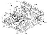
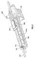
- FIG. 1is a perspective view of a medical insertion device in accordance with embodiments of the present invention.
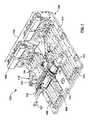
- FIG. 2is a perspective view of a medical insertion device according to various embodiments of the invention.
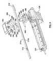
- FIG. 3is a perspective view of an end effector assembly isolated from the medical insertion device of FIG. 2 , according to various embodiments of the invention.
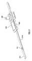
- FIG. 4is an exploded view of the end effector assembly shown in FIG. 3 .
- FIG. 5is a perspective view showing some components of a cannula holder assembly isolated from the medical insertion device of FIG. 2 , according to various embodiments of the invention.
- FIG. 6is a perspective view showing the end effector assembly of FIG. 3 according to various embodiments of the invention.
- FIGS. 7A and 7Bare views from the underside of the end effector assembly of FIG. 3 showing locked and unlocked positions of a movement locking mechanism.
- FIG. 8is a perspective view of a cannula holder to be coupled to a cannula holder mount according to various embodiments of the invention.
- FIG. 9is another perspective view of a cannula holder to be coupled to a cannula holder mount according to various embodiments of the invention.
- FIG. 10is a side view of a cannula holder to be coupled to a cannula holder mount according to various embodiments of the invention.
- FIG. 11is a perspective view showing a cannula holder coupled to a cannula holder mount according to various embodiments of the invention.
- FIGS. 12A, 12B and 12Care perspective views showing insertion and locked positions of a cannula in the cannula holder shown in FIG. 8 .
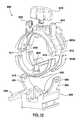
- FIG. 13is a perspective view of a tool mount adaptor according to embodiments of the present invention.
- FIG. 14is an exploded view of the tool mount adaptor shown in FIG. 13 .
- FIGS. 15A, 15B and 15Cshow various medical instruments secured by a tool mount adaptor according to various embodiments of the invention.
- FIG. 16is a perspective view showing a tool mount adaptor securing a medical instrument and showing the relationship of a tool mount adaptor with an end effector interface according to some embodiments of the invention.
- FIG. 17is a perspective view showing a tool mount adaptor secured to an end effector interface according to some embodiments of the invention.
- FIGS. 18 and 19are perspective views depicting an anesthesia tool attached to a collar of a tool mount adaptor according to various embodiments of the present invention.
- FIGS. 20 and 21are perspective views showing the tool mount adaptor shown in FIGS. 18 and 19 without the anesthesia tool.
- FIG. 22is a planar view of an anesthesia tool attached to the collar of the tool mount adaptor shown in FIG. 19 .
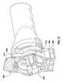
- FIG. 23is a perspective view depicting a vacuum assisted biopsy (VAB) tool attached to a collar of the tool mount adaptor according to an embodiment of the present invention.
- VABvacuum assisted biopsy
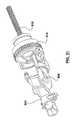
- FIG. 24is a perspective view depicting the tool mount adaptor shown in FIG. 23 .
- FIG. 25is an exploded view of the tool mount adaptor shown in FIG. 23 .
- FIGS. 26A and 26Bare perspective views showing a needle guide according to embodiments of the invention.
- FIG. 27is a perspective view showing a needle guide coupled to a cannula holder according to various embodiments of the invention.
- FIG. 1shows medical insertion device 100 in accordance with some embodiments of the present invention.
- medical insertion device 100can be used in conjunction with an imaging system (not shown here), such as a magnetic resonance imaging (MRI) system, when the imaging system is in use.
- an imaging systemsuch as a magnetic resonance imaging (MRI) system
- Medical insertion device 100can include frame 104 , which can at least partially form a housing of medical insertion device 100 .
- Medical insertion device 100further includes linear slide assembly 106 mounted or connected to frame 104 .
- Medical insertion device 100further includes rotary drive assembly 108 for generally driving the linear slide assembly 106 , and a carriage assembly 110 for moving along the linear slide assembly 106 .
- Frame 104can include a baseplate 112 and a drive support plate 114 connected thereto to at least partially form a housing of medical insertion device 100 .
- the framecan include a wall(s), such as a front wall, side walls, a back wall, a top cover, and a bottom wall for protecting components of the medical insertion device, such as from dust or from a patient's bodily fluids, or for strengthening the structure of medical insertion device as required or desired.
- Frame 104can also include drive plate strengthening brackets (not shown) for strengthening the connection between baseplate 112 and drive support plate 114 as required or desired.
- the front wallcan define an opening for operation of components of the invention, as described further below.
- the framecan be integrated into or forms part of a frame that houses (not shown here) the imaging system (not shown here) with which medical insertion device interacts.
- the framecan be panel-shaped to fit within restricted environments having a limited height.
- the medical insertion devicecan be designed to act cooperatively with an imaging device according to various embodiments of the invention. For example, it can be sized to fit underneath the headrest of a patient support structure that maintains the patient in a face-down position for MRI breast imaging. This is an additional constraint on the space requirements imposed by MRI environment, including, but not limited to, the size and shape of the MRI patient bed and the dimensions of the MRI bore.
- Linear slide assembly 106can be connected to frame 104 at baseplate 112 .
- the linear slide assemblycan be connected to the frame by any means known in the art, such as welding, bolting, or riveting.
- the medical insertion devicecan support, control and drive a medical instrument and/or a cannula as described further below.
- the medical insertion devicecan generally be used to retain, position, and effect insertion of the medical instrument and/or cannula into a patient.
- the medical insertion devicecan generally provide a variety of degrees of freedom, including linear, angular and/or rotational degrees of freedom, for positioning the medical instrument and/or the cannula prior to insertion of the medical instrument and/or the cannula into the patient.
- a tool mount adaptormay be coupled to the medical insertion device to secure the medical instrument to the medical insertion device.
- the medical insertion devicecan also include a sensor(s), such as a force sensor(s), for detecting the tissue being penetrated and for preventing accidental excursion into an incorrect tissue, such as a chest wall.
- the linear slide assemblycan function to position and/or orient the medical instrument and/or cannula for insertion into a patient.
- medical insertion device 100can further include a rotary drive assembly 108 mounted to drive support plate 114 for generally driving linear slide assembly 106 , and a carriage assembly 110 for moving along linear slide assembly 106 .
- Rotary drive assembly 108can drive linear slide assembly 106 to different positions and configurations, thereby orienting medical instrument 102 and/or cannula 103 for insertion into a patient.
- the linear slide assemblycan also be driven by direct linear drives attached directly to the slide assembly. This could be done with piezoelectric motors actuated against a linear slide assembly mounted to the frame or medical insertion device housing. Other means of operating the linear slide assembly would be readily apparent to the skilled person.
- carriage assembly 110can include elongate mounting arm 120 , wherein mounting arm 120 includes an insertion track 122 , which runs along a length of the mounting arm 120 .
- Carriage assembly 110can further comprise insertion carriage 124 , which can be slideably mounted to insertion track 122 .
- Insertion carriage 124can include a mechanism (not shown) which can propel insertion carriage 124 along the insertion track 122 .
- the mechanismcan be any suitable mechanism known in the art, such as a pneumatic or piezoelectric motor, if MRI compatibility is required, or an inductive, or other similar electric, motor.
- movement of insertion carriage 124 along insertion track 122can cause medical instrument 102 to move along insertion axis 127 .
- insertion track 122can define insertion direction 127 .
- components of the carriage assemblycan include a force sensor(s) to detect the tissue being penetrated, and for prevention of accidental excursion into the incorrect tissue (e.g. a chest wall).
- the alignment of the insertion axiscan be confirmed before insertion via fiducial targets mounted either on the medical insertion device 100 or on the attached medical instrument.
- fiducial targetscan be mounted on a separate component that integrates with the robotic manipulator system or medical insertion device.
- fiducial targetscan be mounted onto a patient support, such as a table that a patient lies on during an MRI procedure. Motion can then be easily limited to along the confirmed axis during any contact with the patient.
- the baseplatecan include alignment fiducials or other alignment markers for tracking the location of components of the medical insertion device relative to an absolute coordinate reference frame.
- the alignment fiducialsprovide an “absolute” or “global” reference frame for the system to which all real and virtual representations can be associated.
- baseplate 112can include alignment fiducials 113 for tracking the location of components of medical insertion device 100 relative to an absolute coordinate reference frame when viewing virtual representations, such as when using an imaging system (not shown here) to assist with a medical procedure.
- Alignment fiducials 113can be associated with a variety of locations, such as the location of medical instrument 102 or cannula 103 itself, for correlation or registration purposes, as would be understood by those skilled in the art.
- alignment fiducials 113 attached to specific reference locations on the baseplate 112can be used along with known or measured positions of the subcomponents of medical insertion device 100 to calculate the position of medical instrument 102 or cannula 103 . These positions could be determined, for example, using medical images, encoders associated with the moving sub-components of the medical insertion device, or by some other means as would be understood by those skilled in the art.
- the alignment fiducialcan include MR molecular tagging, which results in an increased conspicuity for accurate identification of the fiducial in MR images.
- linear slide assembly 106is folded in order to provide medical insertion device 100 in a more compact form.
- carriage assembly 110can support the end effector assembly 200 (described further below) through an opening defined in front wall 104 A such that end effector assembly 200 is free of the drive assembly components.
- the medical instrument(not shown) can be operated as a side mount, where the medical instrument is attached to the medical insertion device 100 generally from a direction that is perpendicular to front wall 104 A.
- This configurationcan allow accessing a patient and exchanging medical devices and the like simpler and safer, with less chance to unintentionally interact with the structural and moving components of the medical insertion device 100 .
- the general function of the medical insertion device 100has not been changed in this alternate configuration.
- the basis for motion and positioning of medical instrument 102is a function of the relative position of four independent joints, mounted with two at each end of the end effector assembly 200 and one motor to allow motion along the end effector assembly 200 in the insertion/retraction direction 127 .
- the direction of attachmentis orthogonal to the insertion axis to reduce any chances of moving the medical instrument toward the patient unintentionally.
- this directionallows for a medical instrument changing system to be added more easily and simplifies the design of such a medical instrument changing system.
- the medical instrument changing systemcan be constructed such that the manipulator drives to the position where it picks up the medical instrument, and then the orthogonal ‘stroke’ to install the medical instrument would be short when compared to rear loading along the insertion axis.
- An end effector assemblycan be an assembly that supports and at least partially controls a medical instrument and/or cannula for insertion into a patient along the insertion axis.
- end effector assembly 200can comprise a cannula holder assembly which comprises cannula track 210 .
- Cannula track 210can generally extend along a length of the medical insertion device.
- Cannula track 210can define fastener opening 214 , through which fastener 212 can be inserted to fasten cannula track 210 to carriage assembly 110 .
- Cannula track 210can be fastened to carriage assembly 110 in any fashion known to the skilled person, as long as the functions of the end effector assembly according to the present invention are not substantially impeded.
- Cannula holder assemblycan further comprise a cannula carriage which comprises cannula holder mount 204 .
- End effector assembly 200can further comprise end effector interface 206 , which can operably interact with cannula holder mount 204 , as described further below.
- Cannula holder mount 204can be slideably mounted to cannula track 210 by any mechanism known in the art.
- cannula track 210can define sets of teeth, e.g., notches 211 , along its opposing elongated sides.
- the cannula carriagecan further comprise a demobilizer. In a demobilization mode, the demobilizer can be adapted to restrict movement of the cannula carriage along the cannula track and in a mobilization mode allows movement of the cannula carriage along the cannula track.
- the demobilizercan use a lever mechanism to engage or disengage the notches along the sides of the cannula track to restrict or allow movement of the cannula carriage along the cannula track.
- the demobilizercan be, for example, movement lock 208 , which can comprise guide plate 218 and side tabs 216 and 220 .
- Side tabs 216 and 220can comprise side tab fastening appendages 226 and 224 respectively for rotatably fastening each side tab to cannula holder mount 204 via cannula holder mount fastening appendages 238 and 222 respectively, each defined on the underside of cannula holder mount 204 .
- Side tabs 216 and 220each also define pivots 230 and 228 respectively and pawls 240 and 242 respectively.
- Guide plate 218defines guide plate openings 232 and 234 and fastening pivot 236 .
- Fastening pivotis rotatably fastened to cannula holder mount 204 .
- Each guide plate opening 232 and 234slidably engage with pivots 228 and 230 respectively.
- movement lock 208is shown assembled and fastened to cannula holder mount 204 and cannula track 210 , viewed from the underside of cannula holder mount 204 (cannula track 210 is transparent for viewing purposes).
- FIG. 7Ashows the configuration where movement lock 208 is in the locked position.
- pawls 240 and 242each engage a first set of teeth and a second set of teeth, respectively, e.g., notches 211 a and 211 b , in order to prevent cannula holder mount 204 from sliding in the insertion direction (towards the patient when in operation) or the retraction direction (away from the patient) along insertion axis 127 .
- FIG. 7Bshows the configuration where movement lock 208 is in the unlocked position. In the unlocked position each of pawls 240 and 242 do not engage notches 211 a and 211 b respectively. Movement lock 208 is biased to be in the locked position.
- the demobilizercan comprises a toggle mechanism for disengaging the first pawl from the first set of teeth when the second pawl is disengaged from the second set of teeth, and for disengaging the second pawl from the second set of teeth when the first pawl is disengaged from the first set of teeth.
- movement lock 208can be designed such that, if side tab 216 is moved in a manner that pawl 240 becomes disengaged from notches 211 a , then pivot 230 will move along the oblong shape of guide plate opening 234 . This movement will force guide plate 218 to pivot around fastening pivot point 236 such that the corresponding motion of guide plate opening 232 will cause pivot 228 to move along guide plate opening 232 .
- pivot 228will cause side tab 220 to pivot around side tab fastening appendage 224 , which in turn can cause pawl 242 to disengage from notches 211 b .
- pawl 242can cause either of side tab 216 or 220 to disengage from notches 211 a or 211 b respectively.
- Movement lock 208can prevent cannula holder mount 204 from moving along either direction of cannula track 210 .
- notches 211 a and 211 bare not mirror images of each other through axis 127 . Rather, notches 211 a are notched in the opposite direction from notches 211 b . Therefore, each of pawls 240 and 242 prevent cannula holder mount 204 from sliding along cannula track 210 in one direction, while allowing movement in the other direction.
- pawl 240generally prevents motion of cannula holder mount 204 in one direction of axis 127 and pawl 242 generally prevents motion in the opposite direction
- movement lock 208generally does not allow cannula holder mount 204 to move in either direction unless one or both pawls 240 and 242 are disengaged from the respective notches 211 a and 211 b .
- guide plate opening 234can be designed such that it is slightly larger than guide plate opening 232 .
- disengaging pawls 240 and 242 from the respective notches 211 a and 211 bcan occur in more than one fashion.
- side tab 220defines lever 250 , which can be manually pressed such that side tab 220 pivots around side tab fastening appendage 224 disengages pawl 242 from notches 211 b .
- the insertion carriagecan include a demobilizer-disengaging member adapted to set the demobilizer to a mobilization mode.
- the end effector interfacecan include a demobilizer-disengaging member adapted to set the demobilizer to a mobilization mode.
- another method of disengaging pawls 240 and 242 from the respective notches 211 a and 211 bcan involve the interaction of end effector interface 206 with side tab 216 , which can further comprise ramp 244 .
- End effector interface 206can be fastened to insertion carriage 124 by screws, glue, or any other means known in the art. End effector interface 206 can define a space through which cannula track 210 can be disposed. End effector interface 206 can be mechanically powered through carriage assembly 110 through means such as a piezoelectric stepper motor housed inside the insertion carriage 124 such that end effector interface 206 can automatically move in either direction along cannula track 210 . Other means could be an electric motor and/or gear or drive band mechanism. End effector interface 206 can comprise receiving members 402 and 404 and protrusion 406 . Receiving members 402 and 404 can each define receiving member openings 408 and 410 respectively.
- receiving members 402 and 404can extend generally perpendicular to insertion axis 127 and can also at least partially define mounting tray 600 .
- protrusion 406can engage ramp 244 , which causes pawl 240 to disengage from notches 211 a and allows cannula holder mount 204 to move in an insertion direction along axis 127 .
- end effector interface 206retreats from engagement with cannula holder mount 204 , cannula holder mount 204 becomes locked at the location along cannula track 210 at which end effector interface 206 left it.
- ramp 244 and guide plate opening 234can be constructed such that only pawl 240 disengages from notches 211 a , while pawl 242 remains engaged with notches 211 b , when protrusion 406 engages ramp 244 .
- Thishas the function of allowing only forward motion of cannula holder mount 204 when end effector interface 206 moves in an insertion direction along axis 127 . Due to pawl 242 being engaged with notches 211 b , this has the secondary function of ensuring that cannula holder mount 204 does not move backwards along axis 127 once end effector interface 206 retreats from engagement with cannula holder mount 204 .
- Cannula holder mount 204can be adapted to receive cannula holder 506 .
- Cannula holder 506comprises securing mechanism 508 , to which cannula 103 can be reversibly secured.
- securing mechanismdefines securing mechanism slot 510 which can assist in securing a cannula 103 to cannula holder 506 .
- cannula 103can define appendage 542 , which can be adapted to securely engage with securing mechanism slot 510 when cannula 103 is secured to cannula holder 506 .
- cannula 103is shown in relation to cannula holder 506 in three positions: (i) ready to be positioned ( FIG. 12A ), (ii) positioned but not locked ( FIG. 12B ), and (iii) locked in place ( FIG. 12C ).
- Securing mechanism 508can be designed to securely fit the dimensions of any cannula 103 , such as the dimensions of the ATECTM cannula.
- cannula 103When properly fitted, cannula 103 is generally parallel to axis 127 and will travel only on this axis as cannula holder mount 204 moves along cannula track 210 .
- cannula holder 506ensures that the cannula is positioned such that, for example, a needle of a vacuum assisted biopsy (VAB) tool can pass through the hollow middle portion of cannula 103 .
- VABvacuum assisted biopsy
- Cannula holder 506further comprises tray 514 which is generally shaped to allow passage of medical instrument 102 .
- Tray 514defines tray opening 512 which generally pieces together with a portion of cannula holder mount 204 .
- Cannula holder 506further comprises cannula holder attachments 504 and 520 on the underside of tray 514 .
- Cannula holder attachments 504 and 520can securely attach through a snap-fit to mating attachments 516 and 518 , which are defined on generally opposing ends of cannula holder mount 204 .
- cannula holder 506to cannula holder mount 204
- Other methods of securing cannula holder 506 to cannula holder mount 204will be readily apparent to the skilled person, and include pin/socket connectors, clips, wrap-around parts, friction fit, permanent or temporary adhesives, screws, and the like. Attaching cannula holder 506 to cannula holder mount 204 allows cannula 103 , when secured to cannula holder 506 , to move co-axially with and be controlled by the movement of cannula holder mount 204 .
- cannula holder mount 204is not able to move without manual intervention.
- Other possible mechanisms recognized by the skilled personcould involve implementing an independent actuator or motor to move cannula holder mount 204 without the need for manual intervention.
- Tool mount adaptor 800which can releasably attach to end effector interface 206 , will be further described according to another embodiment of the invention.
- Tool mount adaptor 800can comprise collar 802 , which can be comprised of more than one interconnecting piece.
- collar 802is comprised of pieces 802 a and 802 b , which can releasably couple to each other to form collar 802 .
- tool mount adaptor 800can function to operably connect medical instrument 102 to medical insertion device 100 .
- Collar 802can be releasably secured to medical instrument 102 or cannula 103 for attachment to mounting tray 600 of end effector interface 206 .
- the inner diameter of collar 802may be, for example, about 41.8 mm. This diameter defines the maximum diameter of tool or medical instrument 102 that can be accommodated by the tool mount adaptor; alternately, increasing the size of the tool mount adaptor will consequently increase this diameter, allowing larger tools to be held at the expense of limiting range of motion due to collisions with the structure of the medical insertion device 100 or surrounding structure (e.g., the imaging system or patient).
- Collar 802can attach to any suitable medical instrument, and can allow a variety of medical instruments to be operable with medical insertion device 100 . In other embodiments, collar 802 can be integrated into medical instrument 102 for simplifying setup of medical instrument 102 for use with medical insertion device 100 .
- collar 802can be used to mount different medical instruments to medical insertion device 100 such as a trocar tool 606 ( FIG. 15A ), an anesthesia tool 608 ( FIG. 15B ), or a biopsy tool 610 ( FIG. 15C ).
- medical instruments or toolssuch as needle based diagnostic or therapeutic devices such as ablative, fibre-optic, or other technologies, that fit within the collar 802 can be accommodated for use with medical insertion device 100 through an appropriately modified tool mount adaptor 800 as would be appreciated by a skilled person.
- tool mount adaptor 800can include latch 604 , which can secure, or aid in securing, anesthesia tool 608 to tool mount adaptor 800 .
- the use of several tool mount adaptors 800 coupled to different medical instruments 102could allow for an entire clinical procedure or aspects of a clinical procedure to be conducted robotically using medical insertion device 100 .
- Collar 802can include tab members 806 and 808 , which operably connect to connection ends 812 and 814 , respectively. Connection ends each define nubs 816 and 818 on their inner surfaces. Upon connecting tool mount adaptor 800 to end effector interface 206 , tab members 806 and 808 can be depressed inwardly generally towards each other in order to extend connection ends 812 and 814 outwardly and against the bias. Collar 802 can then be placed in mounting tray 600 and tab members 806 and 808 can be released, thereby allowing receiving member openings 408 and 410 to securely receive nubs 816 and 818 .
- openingscan be defined on the connection ends while nubs are defined on the receiving members.
- securing collar 802 to mounting tray 600including, but not limited to, a screw and threaded hole fixture between aligned and touching parts of securing collar 802 and mounting tray 600 , or a friction fit or tongue-and-groove construction.
- connection ends 812 and 814 and nubs 816 and 818can be made, at least partially, from a resilient material such as a thermoplastic, thermoset plastic, or a composite material such as fibreglass or carbon fibre.
- connection ends 812 and 814can include hinges and can be spring-biased to maintain the engagement of connection ends 812 and 814 to receiving member openings 408 and 410 .
- mounting tray 600can include receiving members 402 and 404 , which can comprise of multiple “fingers”, and not necessarily just single members as shown in the figures. Furthermore, receiving members 402 and 404 , may or may not conform exactly to the shape of the medical instrument 102 and they can extend around medical instrument 102 to varying degrees (e.g., they are shown to extend over approximately half of the circumference of a cylinder in the embodiment shown in the figures). The exact dimensions of receiving members 402 and 404 will depend on the requirements of the specific embodiment of the invention.
- collar 802can include lockout tab 810 , which can prevent the accidental release of collar 802 from the mounting tray of end effector interface 206 .
- lockout tab 810When lockout tab 810 is in a securement mode, it can restrict the ability of an operator from disengaging connection ends 812 and 814 by limiting access to tab members 806 and 808 .
- lockout tab 810When lockout tab 810 is in instrument changing mode, it can allow an operator to disengage connection ends 812 and 814 by operating tab members 806 and 808 .
- itcan be possible for an operator to mount or remove medical instrument 102 with one hand. For example, an operator can hold a portion of medical instrument 102 generally near collar 802 .
- connection ends 812 and 814are also possible by methods such as, but not limited to, a cover over the entirety of operating tab members 806 and 808 that does not allow their operation.
- collar 802is designed to securely attach to a medical instrument 102 in order to allow quick fastening to medical insertion device 100 .
- multiple tool mount adaptors 800can be on hand, each attached to a different medical instrument 102 . This will allow quick and secure interchangeability during a procedure on a patient.
- Tool interface feature 804is shown as an example embodiment of features that may be fashioned into the interior surface of tool mount adaptor 800 .
- Features such as tool interface feature 804may be constructed to ensure a secure, slip-free, and consistent mounting of a medical instrument 102 in a specific manner, such that the tip of medical instrument 102 will always be in a known location relative to the end effector interface 206 . It is understood by persons skilled in the art that the exact nature of a tool interface feature is dependent on the specific surface features medical instrument to which the tool mount adaptor is being designed to fit. These features can include, but would not be limited to, the variable shape of the housing and/or grooves or other features that consistently form part of the outer surface of the medical instrument.
- the medical instrumentis held securely in the tool mount adaptor such that the location of the tip of the tool can be calculated to a high degree of accuracy. In some embodiments, the medical instrument is held securely in the tool mount adaptor such that the location of the tip of the medical instrument can be calculated to a millimeter degree of accuracy or a sub-millimeter degree of accuracy.
- the medical instrumentis held securely in the tool mount adaptor such that the location of the tip can be calculated to a 2 mm degree of accuracy, a 1 mm degree of accuracy, a 0.9 mm degree of accuracy, a 0.8 mm degree of accuracy, a 0.7 mm degree of accuracy, a 0.6 mm degree of accuracy, a 0.5 mm degree of accuracy, a 0.4 mm degree of accuracy, a 0.3 mm degree of accuracy, a 0.2 mm degree of accuracy or a 0.1 mm degree of accuracy.
- the medical instrumentis held securely in the tool mount adaptor such that the location of the tip of the medical instrument relative to the tool mount adaptor deviates to a very small degree.
- the medical instrumentis held securely in the tool mount adaptor such that the location of the tip of the medical instrument relative to the tool mount adaptor deviates less than 1 mm, less than 0.9 mm, less than 0.8 mm, less than 0.7 mm, less than 0.6 mm, less than 0.5 mm, less than 0.4 mm, less than 0.3 mm, less than 0.2 mm, less than 0.1 mm, less than 0.09 mm, less than 0.08 mm, less than 0.07 mm, less than 0.06 mm, less than 0.05 mm, less than 0.04 mm, less than 0.03 mm, less than 0.02 mm or less than 0.01 mm.
- the medical instrument or toolcan be any instrument generally used for insertion into a specimen, such as a patient, and can include, but is not limited to, trocars, syringes, needles, fibreoptic sensors, interstitial imaging devices, biopsy tools, probes, or ablative tools.
- medical instrument 102can include main body 702 and elongate member 704 such as a needle which extends from main body 702 .
- elongate member 704is formed from MR compatible materials such as carbon fibre, ceramic, or titanium.
- a biopsy toolsuch as a vacuum assisted biopsy device, as would be understood in the art.
- Elongate member 704can also include an ablative tool such as Radio Frequency (RF) ablation, focused ultrasound, cryotherapy, laser and other ablative technologies that are administered within the cancerous region causing cell destruction with minimal damage to surrounding tissues.
- the medical instrumentcan also include a detector such as a probe, ultrasound probe, or fiber optic probe. The detector can also include an MRI coil to provide higher resolution in situ imaging.
- the medical instrumentcan be integrated with the end effector interface and the tool mount adaptor to result in a dedicated-purpose insertion device.
- the medical instrumentcan include an end effector or end effectors.
- medical instrument 102can be mounted to medical insertion device 100 generally laterally to axis 127 .
- Collar 802with attached medical instrument 102 , can couple to mounting tray 600 laterally.
- Collar 802having medical instrument 102 secured therein, can be attached to end effector interface 206 through a securing mechanism as described herein.
- Medical instruments interfaced with the medical insertion devicecan be inserted into a patient for various purposes, such as for therapeutic or diagnostic purposes.
- Medical instrumentscan include biopsy tools for taking tissue samples, such as vacuum assisted biopsy (VAB) tools or devices available from ATECTM, or other manufacturers of similar VAB tools or devices; ablative tools for removing unwanted tissue, such as radio frequence (RF) ablation, focused ultrasound, cryotherapy, laser and other ablative technologies; detectors for determining characteristics of tissue such as probes, ultrasound probes, or fibre optic probes, the detectors may include an MRI coil to provide higher resolution in situ imaging; or end effectors for general manipulation during an operation. Medical instruments may be inserted into a patient to an insertion depth in accordance with a particular procedure.
- VABvacuum assisted biopsy
- RFradio frequence
- detectorsfor determining characteristics of tissue such as probes, ultrasound probes, or fibre optic probes, the detectors may include an MRI coil to provide higher resolution in situ imaging; or end effectors for general manipulation during an
- the insertion depthmay be predetermined by an operator, or can be determined during insertion by reference to sensors, such as force feedback sensors for determining the type of tissue the medical instrument has been inserted into, or imaging technologies, such as, but not limited to, cameras, x-ray systems, ultrasound systems, positron emission tomography (PET) systems, positron emission mammography (PEM) systems, CT laser mammography systems, and molecular biological imagers.
- sensorssuch as force feedback sensors for determining the type of tissue the medical instrument has been inserted into, or imaging technologies, such as, but not limited to, cameras, x-ray systems, ultrasound systems, positron emission tomography (PET) systems, positron emission mammography (PEM) systems, CT laser mammography systems, and molecular biological imagers.
- PETpositron emission tomography
- PETpositron emission mammography
- CT laser mammography systemsand molecular biological imagers.
- FIGS. 16, 17, 18, 19, 20, 21 and 22show other embodiments of the tool mount adaptor, which can be mounted to end effector interface 206 , described above, or a similar adaptor of a robotic device that is designed to position interventional tools at a specific location.
- the medical instrumentcan be an anesthesia tool, for example, a syringe.
- tool mount adaptor 800can contain a latch 604 to hold an off-the-shelf syringe 908 .
- Tool mount adaptor 800can employ physical (i.e., mechanical) mechanisms to ensure that the off-the-shelf syringe 908 is secured to tool mount adaptor 800 .
- tool mount adaptor 800can be constructed so that an off-the-shelf needle 910 mounted to the off-the-shelf syringe 908 will be aligned with a known trajectory.
- the tool mount adaptor 800is translated in a fashion that is co-linear with the centerline of the off-the-shelf syringe 908 (e.g., by a robotic or mechanical manipulator system such as medical insertion device 100 along axis 127 )
- the off-the-shelf needle 910can travel in a straight line along this trajectory.
- tool mount adaptor 800can also mount the off-the-shelf syringe 908 such that if (a) the syringe dimensions are known and (b) the needle length is known, then the location of the tip of the off-the-shelf needle 910 can be calculated to a high degree of accuracy. Consequently, the trajectory of the tip will be along the same path as the main body of the off-the-shelf needle 910 , and, therefore, (a) the trajectory of the tip and (b) the final placement of the full length of the off-the-shelf needle 910 can be calculated as well.
- Tool mount adaptor 800can also be adapted to depress or retract the syringe plunger 902 of the off-the-shelf syringe 908 .
- tool mount adaptor 800comprises a linear screw 912 that can interface with a drive gear 914 .
- the drive gear 914interfaces with another set of gears on a robotic manipulator, for example, medical insertion device 100 such that a motor (that is part of the robotic manipulator) can cause the syringe plunger 902 to be depressed or retracted.
- the robotic devicewill only be able to depress the syringe plunger 902 (i.e., will only be able to expel the injectate from the syringe). If, however, a means is provided for the linear screw 912 to couple with the syringe plunger 902 (e.g., a snap-on clip that secures them to each other), then the direction of rotation of the drive gear 914 , as initiated by the robotic device, will determine whether the syringe plunger 902 is depressed (e.g., for deploying anesthetic) or retracted (e.g., for aspirating fluid from a cyst).
- a meansis provided for the linear screw 912 to couple with the syringe plunger 902 (e.g., a snap-on clip that secures them to each other)
- the direction of rotation of the drive gear 914as initiated by the robotic device, will determine whether the syringe plunger 902 is depressed (e.g., for deploying
- the mechanism by which the syringe plunger 902 is depressed or retractedcan be fully decoupled from physical motion (translation or rotation) of the tool mount adaptor itself.
- an independent rotating gearactuates the drive gear 914 on the tool mount adaptor 800 . This allows the off-the-shelf needle 910 to be positioned at a defined spatial location, without depressing or retracting the syringe plunger 902 . It also allows the options of (a) leaving the off-the-shelf needle 910 at a known location while depressing (e.g.
- the off-the-shelf needle 910traverses a defined path with or without the syringe plunger 902 being depressed or retracted.
- tool mount adaptor 800can contain “tight fit” moulds 1002 and 1004 to secure an off-the-shelf biopsy tool to a robotic end effector. These “tight fit” moulds 1002 and 1004 may contain internal grooves and shoulders that interface with corresponding features on a medical instrument to ensure a “tight fit” assembly. Alternatively, this interface may be secured by screws, glue, or any other means known in the art.
- Tool mount adaptor 800can be constructed so that an off-the-shelf biopsy tool 1006 will be aligned with a known trajectory.
- the tool mount adaptor 800is translated in a fashion that is co-linear with the centerline of the off-the-shelf biopsy tool 1006 (e.g., by a robotic or mechanical manipulator system such as medical insertion device 100 along axis 127 )
- the off-the-shelf biopsy tool 1006can travel in a straight line along this trajectory.
- Tool mount adaptor 800can also mount the off-the-shelf biopsy tool 1006 such that if the length of the biopsy tool needle is known, then the location of the tip of the off-the-shelf biopsy tool 1006 can be calculated to a high degree of accuracy.
- the trajectory of the biopsy tool tipwill be along the same path as the main body of the off-the-shelf biopsy tool 1006 , and, therefore, (a) the trajectory of the tip and (b) the final placement of the full length of the off-the-shelf biopsy tool 1006 can be calculated as well.
- Tool mount adaptor 800can also be adapted to roll the off-the-shelf biopsy tool 1006 . This roll functionality may be used to rotate the aperture of the biopsy tool around the axis of the biopsy tool, which could enable 360° of sampling.
- tool mount adaptor 800comprises a drive gear integrated into “tight fit” moulds 1002 and 1004 .
- the drive gear on “tight fit” moulds 1002 and 1004interfaces with another set of gears on a robotic manipulator, for example, medical insertion device 100 such that a motor (that is part of the robotic manipulator) can cause the off-the-shelf biopsy tool 1006 to be rolled.
- the direction of rotation of the drive gearis controlled by the robotic device, and will determine whether the off-the-shelf biopsy tool 1006 is rotated clockwise or counterclockwise.
- the mechanism by which the off-the-shelf biopsy tool 1006 is rotatedcan be fully decoupled from physical motion (translational) of the tool mount adaptor 800 itself.
- an independent rotating gearactuates the drive gear on “tight fit” moulds 1002 and 1004 . This allows the off-the-shelf biopsy tool 1006 to be positioned at a defined spatial location without any rotational motion. It also allows the options of leaving the off-the-shelf biopsy tool 1006 at a known location while rotating the aperature window.
- a method for facilitating insertion of a medical instrument in a patient using a medical insertion devicecomprising: (a) a frame; and (b) a carriage assembly connected to the frame comprising: (i) a mounting arm comprising an insertion track; (ii) an insertion carriage adapted to move along the insertion track; and (iii) a tool mount adaptor connected to the insertion carriage, the tool mount adaptor comprising a collar for holding a medical instrument and a medical instrument held in the collar, wherein the tool mount adaptor is releasably attachable to the insertion carriage, the method comprising: moving the insertion carriage along the insertion track in an insertion direction toward the patient.
- the mounting arm of the carriage assemblyfurther comprises a cannula track parallel to the insertion track; and the carriage assembly further comprises a cannula carriage, wherein the cannula carriage comprises a demobilizer, a cannula holder mount for receiving a cannula, and a cannula held in the cannula holder mount, wherein the cannula carriage is adapted to move along the cannula track, and the demobilizer in a demobilization mode is adapted to restrict movement of the cannula carriage along the cannula track and in a mobilization mode allows movement of the cannula carriage along the cannula track.
- insertion carriage 124can move along insertion track 122 along axis 127 toward a patient.
- movement lock 208is engaged as described above to unlock cannula holder mount 204 from cannula track 210 , thereby allowing insertion carriage 124 and cannula holder mount 204 to continue along axis 127 , and ultimately insert medical instrument 102 and/or cannula 103 into the patient.
- medical instrument 102can function as an introducer for an initial insertion into the patient.
- end effector interface 206 and medical instrument 102can retract, causing movement lock 208 to once again lock to cannula track 210 , causing cannula 103 to remain in place in the patient.
- Medical instrument 102 attached to retracted tool mount adaptor 800can then be replaced with alternative instruments and inserted into the patient without additional invasive insertions.
- Medical instrument 102 and cannula 103can operate in conjunction with each other.
- medical instrument 102can be a trocar, which can act as a cutter.
- cannula 103sometimes called an introducer, can be introduced to the desired site within a patient after a trocar is used to create the initial puncture through the patient's skin. Once cannula 103 is placed at the desired site by way of the trocar, the trocar can removed and the cannula can be left in place for other tools to traverse the same path. Cannula 103 can then provide a path through which multiple interventional tools will pass. This avoids extra punctures through the skin and additional trajectories for different tools through the tissue.
- the trocarcan then be exchanged with a different medical instrument, such as, but not limited to, a medical instrument useful for endoscopy, biopsy, anesthesia, ablation, imaging, spectroscopy, aspiration, and the like.
- a medical instrumentuseful for endoscopy, biopsy, anesthesia, ablation, imaging, spectroscopy, aspiration, and the like. This can allow for a variety of procedures to be performed while minimizing the number of invasive insertions into the patient.
- the medical insertion devicecan be used in conjunction with an imaging system (not shown here), such as a magnetic resonance imaging (MRI) system, when the imaging system is in use.
- imaging systemsinclude, but are not limited to, cameras, x-ray systems, ultrasound systems, positron emission tomography (PET) systems, single photon emission compute tomography (SPECT) systems, optical coherence tomography (OCT) systems, optical imaging and/or spectroscopy systems, thermal imaging systems, positron emission mammography (PEM) systems, CT laser mammography systems, and molecular biological imagers.
- a needle guide 1008is also provided.
- the needle guide 1008is designed to mount to the cannula holder mount 204 on the cannula track 210 of the interface and move independently of the tool mount adaptor 800 .
- the needle guide 1008could be constructed to interface with the cannula holder 506 instead of (and in the same manner as) the cannula 103 locks into the cannula holder securing mechanism 508 .
- the needle guide 1008may be placed near the skin surface to guide the off-the-shelf needle 910 to a specific entry point.
- a hole in the needle guide 1008is designed to be in the correct location such that the off-the-shelf needle 910 will pass through it while traversing the trajectory that has already been defined according to the design of the tool mount adaptor 800 .
- the medical insertion device 100pushes the tool mount adaptor 800 forward (via the end effector interface 206 ), the off-the-shelf needle 910 consequently passes through the needle guide 1008 before going into the underlying tissue.
- This needle guide 1008(a) provides a visual cue as to where the off-the-shelf needle 910 will enter the skin and (b) provides mechanical support for maintaining a straight needle path as it enters the tissue.
- suitable materials for the various described assemblies, subsystems and devicescan be, for example, ceramics, thermoplastics, thermoset plastics, carbon fibre, composites, nanoparticle composites, aluminum, titanium, or stainless steel.
- suitable materials for the assemblies, subsystems and devicescan be, for example, magnetic resonance compatible materials.
- MR compatible materialscan be, for example, ceramics, thermoplastics or thermoset plastics.
- suitable materialscan be, for example, carbon fibre, composites, nanoparticle composites, aluminum, titanium, or stainless steel.
- MR compatible motorscan be, for example, piezoelectric motors, pneumatic, vacuum-actuated or hydraulic drivers. If described devices are not intended to be MRI compatible, other materials, such as metal components or standard inductive electrical motors, can be suitable.
- the various described assemblies, subsystems and devicescan be manufactured using additive manufacturing methods.
- the tool mount adaptorcan be manufactured by using, for example, 3D printing.
- 3D printingcan build an object or device from a series of layers, each layer being printed directly on top of a previous layer.
- a 3D printing model for the object or devicecan be created with a computer aided design package or via a 3D scanner.
- the 3D printercan read the design from a 3D printable file and can lay down successive layers of the raw material (for example, liquid, powder, paper or sheet material) to build the model from a series of cross sections. These layers, which may correspond to the virtual cross sections from the CAD model, may be joined or automatically fused to create the final shape of the object or device.
- the 3D printingcan use lasers or electron beams to join or fuse the layers.
- the inventionprovides for the operable co-operation of a tool mount adaptor for securing a medical instrument and a cannula holder for securing a cannula.
- the tool mount adaptorcan be constructed so that off-the-shelf tools or custom tools will be aligned with a known trajectory. This trajectory may be straight or angular as controlled by a robotic manipulator, for example, medical insertion device 100 .
- Tool mount adaptorscan also secure tools such that if the length of the tool is known, then the location of the tip of the tool can be calculated to a high degree of accuracy.
- the trajectory of the biopsy tool tipwill be along the same path as the main body of the tool, and, therefore, (a) the trajectory of the tip and/or (b) the final placement of the full length of the off-the-shelf biopsy tool can be calculated.
- the tool mount adaptorcan be coupled to a medical insertion device comprising a mounting arm, an insertion track mounted on the mounting arm, an insertion carriage adapted to be slideably moveable along the instrument track, and a cannula track mounted on the mounting arm, generally parallel to the insertion track.
- the tool mount adaptorcan be coupled to the insertion carriage and the cannula holder can be coupled to the cannula track such that the medical instrument and the cannula are slideably moveable along the same axis. At least a portion of the body of the medical instrument can be accommodated by the hollow body of the cannula.
- the tool mount adaptorcan disengage the cannula holder and can allow both the tool mount adaptor and the cannula holder to proceed in the insertion direction until the medical instrument and the cannula reach an insertion depth within a patient.
- the tool mount adaptorcan then be retracted, leaving the cannula holder to remain in place. This allows an operator to mount a different medical instrument to the medical insertion device to perform additional tasks while not requiring additional invasive insertions into a patient.
- an insertion mechanismmay be used to move the entire linear slide assembly 106 in the insertion direction 127 to provide the insertion step (rather than from the insertion track 122 ).
- some medical instruments 102may include their own insertion or injection mechanism, which may be automated or manually controllable by a mechanism for insertion.
Landscapes
- Health & Medical Sciences (AREA)
- Surgery (AREA)
- Engineering & Computer Science (AREA)
- Life Sciences & Earth Sciences (AREA)
- Biomedical Technology (AREA)
- Robotics (AREA)
- Nuclear Medicine, Radiotherapy & Molecular Imaging (AREA)
- Heart & Thoracic Surgery (AREA)
- Medical Informatics (AREA)
- Molecular Biology (AREA)
- Animal Behavior & Ethology (AREA)
- General Health & Medical Sciences (AREA)
- Public Health (AREA)
- Veterinary Medicine (AREA)
- Surgical Instruments (AREA)
Abstract
Description
Claims (13)
Priority Applications (1)
| Application Number | Priority Date | Filing Date | Title |
|---|---|---|---|
| US14/906,651US10512511B2 (en) | 2013-07-24 | 2014-07-24 | Multi-function mounting interface for an image-guided robotic system and quick release interventional toolset |
Applications Claiming Priority (3)
| Application Number | Priority Date | Filing Date | Title |
|---|---|---|---|
| US201361857917P | 2013-07-24 | 2013-07-24 | |
| PCT/CA2014/000591WO2015010189A1 (en) | 2013-07-24 | 2014-07-24 | Multi-function mounting interface for an image-guided robotic system and quick release interventional toolset |
| US14/906,651US10512511B2 (en) | 2013-07-24 | 2014-07-24 | Multi-function mounting interface for an image-guided robotic system and quick release interventional toolset |
Publications (2)
| Publication Number | Publication Date |
|---|---|
| US20160157941A1 US20160157941A1 (en) | 2016-06-09 |
| US10512511B2true US10512511B2 (en) | 2019-12-24 |
Family
ID=52392534
Family Applications (1)
| Application Number | Title | Priority Date | Filing Date |
|---|---|---|---|
| US14/906,651Active2035-06-28US10512511B2 (en) | 2013-07-24 | 2014-07-24 | Multi-function mounting interface for an image-guided robotic system and quick release interventional toolset |
Country Status (3)
| Country | Link |
|---|---|
| US (1) | US10512511B2 (en) |
| CA (1) | CA2918879A1 (en) |
| WO (1) | WO2015010189A1 (en) |
Cited By (1)
| Publication number | Priority date | Publication date | Assignee | Title |
|---|---|---|---|---|
| US11547501B2 (en)* | 2016-09-14 | 2023-01-10 | Cmr Surgical Limited | Interfacing a surgical robotic arm and instrument |
Families Citing this family (18)
| Publication number | Priority date | Publication date | Assignee | Title |
|---|---|---|---|---|
| CN114052854B (en) | 2016-07-01 | 2024-11-12 | 直观外科手术操作公司 | Computer-assisted medical system and method |
| GB2599325B (en)* | 2017-02-07 | 2022-08-03 | Cmr Surgical Ltd | Mounting an endoscope to a surgical robot |
| WO2018209042A2 (en) | 2017-05-10 | 2018-11-15 | Mako Surgical Corp. | Robotic spine surgery system and methods |
| US11033341B2 (en) | 2017-05-10 | 2021-06-15 | Mako Surgical Corp. | Robotic spine surgery system and methods |
| USD844768S1 (en)* | 2017-09-06 | 2019-04-02 | Rheem Manufacturing Company | Water heater top cap assembly |
| US11666399B2 (en)* | 2017-11-30 | 2023-06-06 | Covidien Lp | Robotic surgical instrument including instrument rotation based on translation position |
| CN118662240A (en) | 2018-01-26 | 2024-09-20 | 马科外科公司 | End effector, system, and method for impacting a prosthesis guided by a surgical robot |
| GB2570520B8 (en)* | 2018-01-30 | 2023-05-24 | Cmr Surgical Ltd | Interfacing a surgical robotic arm and instrument |
| US12364560B2 (en)* | 2018-03-21 | 2025-07-22 | The Regents Of The University Of California | Rapid and precise tool exchange mechanism for intraocular robotic surgical systems |
| US20210015572A1 (en)* | 2018-03-29 | 2021-01-21 | Intuitive Surgical Operations, Inc. | Surgical instrument actuation systems |
| CN110559078B (en)* | 2018-06-05 | 2021-03-30 | 杭州术创机器人有限公司 | Sleeve fixing assembly for minimally invasive surgery system |
| CA3161864A1 (en) | 2019-11-28 | 2021-06-03 | Microbot Medical Ltd. | Modular robotic system for driving movement of surgical tools |
| EP3984489B1 (en)* | 2020-10-14 | 2025-08-13 | Orthosoft, Inc. | Quick connect for robotic surgery |
| US12102402B2 (en)* | 2021-02-11 | 2024-10-01 | Cilag Gmbh International | Slipper clutch for surgical tool bailout |
| CA3218370A1 (en) | 2021-06-01 | 2022-12-08 | Forsight Robotics Ltd. | Kinematic structures and sterile drapes for robotic microsurgical procedures |
| WO2023181298A1 (en)* | 2022-03-24 | 2023-09-28 | リバーフィールド株式会社 | Retention attachment |
| EP4629924A1 (en)* | 2022-12-11 | 2025-10-15 | Forsight Robotics Ltd. | Robotic surgical procedure with rapid tool exchange |
| FR3147720A1 (en)* | 2023-04-13 | 2024-10-18 | Koelis | Device for holding a medical monitoring device and installation comprising such a device |
Citations (154)
| Publication number | Priority date | Publication date | Assignee | Title |
|---|---|---|---|---|
| US4676142A (en) | 1984-06-04 | 1987-06-30 | Eoa Systems, Inc. | Adapter with modular components for a robot end-of-arm interchangeable tooling system |
| US4710079A (en) | 1985-06-11 | 1987-12-01 | T. M. Smith Tool International Corp. | Quick change spindle adapter for tool holder |
| US4791934A (en) | 1986-08-07 | 1988-12-20 | Picker International, Inc. | Computer tomography assisted stereotactic surgery system and method |
| US4958625A (en)* | 1989-07-18 | 1990-09-25 | Boston Scientific Corporation | Biopsy needle instrument |
| US5047015A (en) | 1989-03-17 | 1991-09-10 | Merit Medical Systems, Inc. | Locking syringe |
| US5078140A (en) | 1986-05-08 | 1992-01-07 | Kwoh Yik S | Imaging device - aided robotic stereotaxis system |
| US5127419A (en)* | 1991-07-02 | 1992-07-07 | Antoine Kaldany | Biopsy instrument with slotted driving member |
| US5176702A (en) | 1991-04-04 | 1993-01-05 | Symbiosis Corporation | Ratchet locking mechanism for surgical instruments |
| WO1994013205A1 (en) | 1992-12-10 | 1994-06-23 | Accuray, Inc. | Apparatus and method for sterotaxic radiosurgery and radiotherapy |
| US5356421A (en) | 1992-10-07 | 1994-10-18 | United States Surgical Corporation | Safety trocar with locking handles |
| US5358474A (en)* | 1991-07-02 | 1994-10-25 | Intermed, Inc. | Subcutaneous drug delivery device |
| US5441042A (en) | 1991-08-05 | 1995-08-15 | Putman; John M. | Endoscope instrument holder |
| WO1996008199A1 (en) | 1994-09-16 | 1996-03-21 | Fischer Imaging Corporation | Magnetic resonance imaging device for tool guiding |
| US5562613A (en)* | 1991-07-02 | 1996-10-08 | Intermed, Inc. | Subcutaneous drug delivery device |
| WO1996039944A1 (en) | 1995-06-07 | 1996-12-19 | Sri International | Surgical manipulator for a telerobotic system |
| US5647361A (en) | 1992-09-28 | 1997-07-15 | Fonar Corporation | Magnetic resonance imaging method and apparatus for guiding invasive therapy |
| US5649956A (en)* | 1995-06-07 | 1997-07-22 | Sri International | System and method for releasably holding a surgical instrument |
| US5754085A (en) | 1992-09-28 | 1998-05-19 | Fonar Corporation | Ferromagnetic yoke magnets for medical magnetic resonance studies |
| US5817106A (en)* | 1995-09-19 | 1998-10-06 | Real; Douglas D. | Stereotactic guide apparatus for use with neurosurgical headframe |
| US5820623A (en) | 1995-06-20 | 1998-10-13 | Ng; Wan Sing | Articulated arm for medical procedures |
| US5906599A (en)* | 1995-11-09 | 1999-05-25 | Intermed, Inc. | Device for delivering biological agents |
| US6023165A (en) | 1992-09-28 | 2000-02-08 | Fonar Corporation | Nuclear magnetic resonance apparatus and methods of use and facilities for incorporating the same |
| US6035228A (en) | 1997-11-28 | 2000-03-07 | Picker International, Inc. | Frameless stereotactic arm apparatus and method of using same |
| WO2000023000A1 (en) | 1998-10-16 | 2000-04-27 | Regents Of The University Of Minnesota | Mri and magnetic stereotaxis surgical system |
| US6165139A (en) | 1993-03-01 | 2000-12-26 | Fonar Corporation | Remotely steerable guide wire with external control wires |
| US6201394B1 (en) | 1992-12-18 | 2001-03-13 | Fonar Corporation | MRI apparatus |
| US6249695B1 (en) | 1997-11-21 | 2001-06-19 | Fonar Corporation | Patient movement during image guided surgery |
| US6280383B1 (en) | 1993-03-01 | 2001-08-28 | Fonar Corporation | Magnetic resonance imaging |
| WO2001075465A1 (en) | 2000-03-30 | 2001-10-11 | Case Western Reserve University | Mr invasive device and method for active mr guidance of invasive devices with target navigation |
| US6335623B1 (en) | 1992-12-18 | 2002-01-01 | Fonar Corporation | MRI apparatus |
| US6404202B1 (en) | 1992-12-18 | 2002-06-11 | Fonar Corporation | MRI magnet with enhanced patient entry and positioning |
| US6414490B1 (en) | 1992-12-18 | 2002-07-02 | Fonar Corporation | MRI magnet with enhanced patient entry and positioning |
| US6437571B1 (en) | 1997-11-21 | 2002-08-20 | Fonar Corporation | MRI apparatus |
| US6436107B1 (en) | 1996-02-20 | 2002-08-20 | Computer Motion, Inc. | Method and apparatus for performing minimally invasive surgical procedures |
| US20020120252A1 (en)* | 1998-02-24 | 2002-08-29 | Brock David L. | Surgical instrument |
| US6451027B1 (en)* | 1998-12-16 | 2002-09-17 | Intuitive Surgical, Inc. | Devices and methods for moving an image capture device in telesurgical systems |
| US20020156395A1 (en)* | 2001-04-20 | 2002-10-24 | Stephens Randy R. | Surgical biopsy device having automatic rotation of the probe for taking multiple samples |
| US6505065B1 (en) | 1999-10-29 | 2003-01-07 | Koninklijke Philips Electronics, N.V. | Methods and apparatus for planning and executing minimally invasive procedures for in-vivo placement of objects |
| WO2003045264A1 (en) | 2001-11-21 | 2003-06-05 | Koninklijke Philips Electronics Nv | Tactile feedback and display in a ct image guided rogotic system for interventional procedures |
| US6620173B2 (en)* | 1998-12-08 | 2003-09-16 | Intuitive Surgical, Inc. | Method for introducing an end effector to a surgical site in minimally invasive surgery |
| WO2004014244A2 (en) | 2002-08-13 | 2004-02-19 | Microbotics Corporation | Microsurgical robot system |
| WO2004069492A2 (en) | 2003-02-04 | 2004-08-19 | Schunk Gmbh & Co. Kg Fabrik Für Spann- Und Greifwerkzeuge | Interchangeable system, in particular interchangeable tool system |
| US20040193146A1 (en)* | 2001-02-15 | 2004-09-30 | Endo Via Medical, Inc. | Robotically controlled surgical instruments |
| WO2004110242A2 (en) | 2003-06-18 | 2004-12-23 | Koninklijke Philips Electronics N.V. | Remotely held needle guide for ct fluoroscopy |
| US6889073B2 (en) | 2000-05-08 | 2005-05-03 | David A. Lampman | Breast biopsy and therapy system for magnetic resonance imagers |
| US20050165328A1 (en)* | 2002-03-19 | 2005-07-28 | Norbert Heske | Biopsy device and biopsy needle module that can be inserted into the biopsy device |
| WO2006025001A1 (en) | 2004-09-01 | 2006-03-09 | Koninklijke Philips Electronics, N.V. | Magnetic resonance marker based position and orientation probe |
| US20060074344A1 (en)* | 2004-09-29 | 2006-04-06 | Hibner John A | Fluid control for biopsy device |
| US20060074346A1 (en)* | 2004-09-29 | 2006-04-06 | Hibner John A | Biopsy apparatus and method |
| US20060122496A1 (en) | 2002-05-17 | 2006-06-08 | Mark George | Method, apparatus, and system for automatically positioning a probe or sensor |
| US7063479B2 (en) | 2000-01-13 | 2006-06-20 | Secretary Of Agency Of Industrial Science And Technology | Link mechanism of surgical robot |
| US20060149163A1 (en)* | 2004-12-29 | 2006-07-06 | Hibner John A | Core sampling biopsy device with short coupled MRI-compatible driver |
| US7127802B1 (en) | 1997-11-21 | 2006-10-31 | Fonar Corporation | Method of fabricating a composite plate |
| US20070119274A1 (en)* | 1996-12-12 | 2007-05-31 | Devengenzo Roman L | Instrument interface of a robotic surgical system |
| US20070239067A1 (en)* | 2005-08-05 | 2007-10-11 | Hibner John A | Tissue Sample Revolver Drum Biopsy Device |
| WO2007136745A2 (en) | 2006-05-19 | 2007-11-29 | University Of Hawaii | Motion tracking system for real time adaptive imaging and spectroscopy |
| US20080140088A1 (en)* | 1996-12-12 | 2008-06-12 | Intuitive Surgical, Inc. | Disposable sterile surgical adaptor |
| US20080167674A1 (en)* | 2007-01-08 | 2008-07-10 | Restoration Robotics, Inc. | Automated delivery of a therapeutic or cosmetic substance to cutaneous, subcutaneous and intramuscular tissue regions |
| US20080249536A1 (en)* | 2007-02-15 | 2008-10-09 | Hansen Medical, Inc. | Interface assembly for controlling orientation of robotically controlled medical instrument |
| WO2008153975A2 (en) | 2007-06-07 | 2008-12-18 | Surgivision, Inc. | Mri-guided medical interventional systems and methods |
| US20090024141A1 (en)* | 2007-05-25 | 2009-01-22 | Hansen Medical, Inc. | Rotational apparatus system and method for a robotic instrument system |
| US7497863B2 (en)* | 2004-12-04 | 2009-03-03 | Medtronic, Inc. | Instrument guiding stage apparatus and method for using same |
| WO2009042136A1 (en) | 2007-09-24 | 2009-04-02 | Surgivision, Inc. | Control unit for mri-guided medical interventional systems |
| WO2009042130A2 (en) | 2007-09-24 | 2009-04-02 | Surgivision, Inc. | Mri-guided medical interventional systems and methods |
| WO2009040677A2 (en) | 2007-04-16 | 2009-04-02 | The Governors Of The University Of Calgary | Methods, devices, and systems useful in registration |
| WO2009042160A1 (en) | 2007-09-24 | 2009-04-02 | Surgivision, Inc. | Surgical marking tools and methods for marking a patient |
| WO2009042155A2 (en) | 2007-09-24 | 2009-04-02 | Surgivision, Inc. | Mri-compatible patches and methods for using the same |
| US20090088666A1 (en)* | 2007-10-01 | 2009-04-02 | Miller Michael E | Surgical device |
| WO2009146176A1 (en) | 2008-04-14 | 2009-12-03 | Blake Larson | Device and method for mri-guided breast interventions |
| WO2009152613A1 (en) | 2008-06-18 | 2009-12-23 | Engineering Services Inc. | Mri compatible robot with calibration phantom and phantom |
| US20100030233A1 (en)* | 2008-07-08 | 2010-02-04 | Whitman Michael P | Surgical attachment for use with a robotic surgical system |
| US20100036245A1 (en)* | 2005-12-02 | 2010-02-11 | Yan Yu | Image-guided therapy delivery and diagnostic needle system |
| US20100041938A1 (en) | 2005-12-02 | 2010-02-18 | The Johns Hopkins University | Multi-imager compatible robot for image-guided interventions and fully automated brachytherapy seed |
| US7666191B2 (en) | 1996-12-12 | 2010-02-23 | Intuitive Surgical, Inc. | Robotic surgical system with sterile surgical adaptor |
| WO2010034099A1 (en) | 2008-09-24 | 2010-04-01 | Cedara Software Corp. | Ac-pc segmentation system and method |
| WO2010044852A2 (en) | 2008-10-14 | 2010-04-22 | University Of Florida Research Foundation, Inc. | Imaging platform to provide integrated navigation capabilities for surgical guidance |
| US20100160810A1 (en)* | 2008-12-18 | 2010-06-24 | Parihar Shailendra K | Multi-Orientation Targeting Set for MRI Biopsy Device |
| US20100280525A1 (en)* | 2009-04-29 | 2010-11-04 | Hansen Medical, Inc. | Flexible and steerable elongate instruments with shape control and support elements |
| US20110098553A1 (en) | 2009-10-28 | 2011-04-28 | Steven Robbins | Automatic registration of images for image guided surgery |
| WO2011057260A2 (en) | 2009-11-09 | 2011-05-12 | Worcester Polytechnic Institute | Apparatus and methods for mri-compatible haptic interface |
| WO2011063511A1 (en) | 2009-11-27 | 2011-06-03 | Mcmaster University | Automated in-bore mr guided robotic diagnostic and therapeutic system |
| US7955322B2 (en)* | 2005-12-20 | 2011-06-07 | Intuitive Surgical Operations, Inc. | Wireless communication in a robotic surgical system |
| US7955321B2 (en) | 2005-01-11 | 2011-06-07 | Hitachi, Ltd. | Surgical operation apparatus and manipulator for use therein |
| US7979157B2 (en) | 2004-07-23 | 2011-07-12 | Mcmaster University | Multi-purpose robotic operating system and method |
| US7979108B2 (en) | 2007-08-27 | 2011-07-12 | William Harrison Zurn | Automated vessel repair system, devices and methods |
| US8114032B2 (en)* | 2001-05-06 | 2012-02-14 | Stereotaxis, Inc. | Systems and methods for medical device advancement and rotation |
| WO2012063266A2 (en) | 2010-11-10 | 2012-05-18 | Perfint Healthcare Pvt. Ltd | Systems and methods for planning image-guided interventional procedures |
| US20120150019A1 (en) | 2009-08-11 | 2012-06-14 | Koninklijke Philips Electronics N.V. | Mri by direct transverse hyperpolarization using light endowed with orbital angular momentum |
| WO2012088321A1 (en) | 2010-12-22 | 2012-06-28 | Viewray Incorporated | System and method for image guidance during medical procedures |
| US20120190965A1 (en) | 2011-01-24 | 2012-07-26 | Shawn Schaerer | MR Compatible Stereoscopic Viewing Device for use in the Bore of an MR Magnet |
| US20120190966A1 (en) | 2011-01-24 | 2012-07-26 | Shawn Schaerer | MR Compatible Fluorescence Viewing Device for use in the Bore of an MR Magnet |
| US8303576B2 (en) | 1998-02-24 | 2012-11-06 | Hansen Medical, Inc. | Interchangeable surgical instrument |
| US20120310112A1 (en) | 2002-04-22 | 2012-12-06 | The Johns Hopkins University | Apparatus for insertion of a medical device during a medical imaging process |
| US20130035583A1 (en) | 2011-08-02 | 2013-02-07 | Samsung Electronics Co., Ltd. | Method and apparatus for processing medical image, and robotic surgery system using image guidance |
| WO2013041994A2 (en) | 2011-09-19 | 2013-03-28 | Koninklijke Philips Electronics N.V. | Integrated mr imaging and interventional coil device, method and system |
| US8427148B2 (en) | 2009-12-31 | 2013-04-23 | Analogic Corporation | System for combining magnetic resonance imaging with particle-based radiation systems for image guided radiation therapy |
| WO2013116240A1 (en) | 2012-01-30 | 2013-08-08 | Inneroptic Technology, Inc. | Multiple medical device guidance |
| US20130218005A1 (en) | 2012-02-08 | 2013-08-22 | University Of Maryland, Baltimore | Minimally invasive neurosurgical intracranial robot system and method |
| US20130231586A1 (en) | 2004-05-21 | 2013-09-05 | Devicor Medical Products, Inc. | Mri biopsy apparatus incorporating a sleeve and multi-function obturator |
| US20130282021A1 (en)* | 2011-10-19 | 2013-10-24 | Ethicon Endo-Surgery, Inc. | Clip applier adapted for use with a surgical robot |
| US20130296886A1 (en) | 1995-06-07 | 2013-11-07 | Sri International | Surgical manipulator for a telerobotic system |
| WO2013187342A1 (en) | 2012-06-15 | 2013-12-19 | Canon Kabushiki Kaisha | Medical manipulator, medical system including the same, medical puncturing system, and biopsy system |
| WO2014003855A1 (en) | 2012-06-27 | 2014-01-03 | Monteris Medical Corporation | Image-guided therapy of a tissue |
| WO2014032046A1 (en) | 2012-08-24 | 2014-02-27 | University Of Houston | Robotic device and systems for image-guided and robot-assisted surgery |
| WO2014036034A1 (en) | 2012-08-27 | 2014-03-06 | University Of Houston | Robotic device and system software, hardware and methods of use for image-guided and robot-assisted surgery |
| WO2014058833A1 (en) | 2012-10-08 | 2014-04-17 | The Johns Hopkins University | Mri-safe robot for transrectal prostate biopsy |
| US20140107665A1 (en)* | 2012-02-02 | 2014-04-17 | Transenterix, Inc. | Mechanized multi-instrument surgical system |
| US20140309661A1 (en)* | 2011-11-08 | 2014-10-16 | Valtech Cardio, Ltd. | Controlled steering functionality for implant-delivery tool |
| WO2014204930A2 (en) | 2013-06-17 | 2014-12-24 | Children's National Medical Center | Patient mounted mri and ct compatible robot for needle guidance in interventional procedures |
| US8986246B2 (en) | 2008-01-16 | 2015-03-24 | Catheter Robotics Inc. | Remotely controlled catheter insertion system |
| US20150100067A1 (en) | 2013-10-08 | 2015-04-09 | University Of Washington Through Its Center For Commercialization | Methods and systems for computer-guided placement of bone implants |
| WO2015061756A1 (en) | 2013-10-24 | 2015-04-30 | Auris Surgical Robotics, Inc. | System for robotic-assisted endolumenal surgery and related methods |
| WO2015124795A1 (en) | 2014-02-24 | 2015-08-27 | UNIVERSITE DE STRASBOURG (Etablissement Public National à Caractère Scientifique, Culturel et Professionnel) | Automatic multimodal real-time tracking of a moving marker for image plane alignment inside a mri scanner |
| US20150257841A1 (en)* | 2014-03-17 | 2015-09-17 | Intuitive Surgical Operations, Inc. | Latch release for surgical instrument |
| US20150265353A1 (en) | 2014-03-18 | 2015-09-24 | Monteris Medical Corporation | Image-guided therapy of a tissue |
| US20150335316A1 (en) | 2014-05-23 | 2015-11-26 | General Electric Company | Mri system for robotically assisted breast biopsy |
| WO2015193479A1 (en) | 2014-06-19 | 2015-12-23 | KB Medical SA | Systems and methods for performing minimally invasive surgery |
| US9222996B2 (en) | 2013-03-15 | 2015-12-29 | The Brigham And Women's Hospital, Inc. | Needle placement manipulator with two rotary guides |
| US20160001038A1 (en) | 2014-07-01 | 2016-01-07 | Auris Surgical Robotics, Inc. | Tool and method for using surgical endoscope with spiral lumens |
| US9271664B2 (en) | 2009-03-04 | 2016-03-01 | Imricor Medical Systems, Inc. | Combined field location and MRI tracking |
| WO2016054256A1 (en) | 2014-09-30 | 2016-04-07 | Auris Surgical Robotics, Inc | Configurable robotic surgical system with virtual rail and flexible endoscope |
| US9326823B2 (en) | 2012-05-02 | 2016-05-03 | University Of Maryland, College Park | Real-time tracking and navigation system and method for minimally invasive surgical procedures |
| WO2016149125A1 (en) | 2015-03-13 | 2016-09-22 | Monteris Medical Corporation | Apparatus and method for neurological treatment |
| US20160270865A1 (en) | 2014-07-01 | 2016-09-22 | Auris Surgical Robotics, Inc. | Reusable catheter with disposable balloon attachment and tapered tip |
| US20160302871A1 (en) | 2015-04-15 | 2016-10-20 | Mobius Imaging, Llc | Integrated medical imaging and surgical robotic system |
| WO2016176683A1 (en) | 2015-04-30 | 2016-11-03 | Memorial Sloan-Kettering Cancer Center | Catheter control mechanism with magnetic resonance imaging-compatible torque |
| US9492241B2 (en) | 2005-01-13 | 2016-11-15 | Mazor Robotics Ltd. | Image guided robotic system for keyhole neurosurgery |
| US9561083B2 (en) | 2014-07-01 | 2017-02-07 | Auris Surgical Robotics, Inc. | Articulating flexible endoscopic tool with roll capabilities |
| US9575148B2 (en) | 2012-11-06 | 2017-02-21 | Imris Inc. | Method for MR-guided brachytherapy with consistent patient positioning |
| US20170086927A1 (en)* | 2015-09-25 | 2017-03-30 | Ethicon Endo-Surgery, Llc | Hybrid robotic surgery with locking mode |
| US20170086932A1 (en)* | 2015-09-25 | 2017-03-30 | Ethicon Endo-Surgery, Llc | Methods for hybrid robotic laparoscopic surgery |
| WO2017066628A2 (en) | 2015-10-14 | 2017-04-20 | Qfix Systems, Llc | Patient trolley and patient transfer device |
| WO2017098543A1 (en) | 2015-12-11 | 2017-06-15 | 株式会社メディカロイド | Robot arm, robotic head, and intraoperative mri system |
| WO2017098544A1 (en) | 2015-12-11 | 2017-06-15 | 株式会社メディカロイド | Robotic bed |
| WO2017099234A1 (en) | 2015-12-11 | 2017-06-15 | 株式会社メディカロイド | Medical system |
| US20170215827A1 (en) | 2016-02-03 | 2017-08-03 | Globus Medical, Inc. | Portable medical imaging system |
| US20170215825A1 (en) | 2016-02-03 | 2017-08-03 | Globus Medical, Inc. | Portable medical imaging system |
| US20170215826A1 (en) | 2016-02-03 | 2017-08-03 | Globus Medical, Inc. | Portable medical imaging system |
| WO2017158180A1 (en) | 2016-03-17 | 2017-09-21 | Koninklijke Philips N.V. | Control unit, system and method for controlling hybrid robot having rigid proximal portion and flexible distal portion |
| US20170296289A1 (en) | 2014-03-18 | 2017-10-19 | Monteris Medical Corporation | Automated therapy of a three-dimensional tissue region |
| WO2017189874A1 (en) | 2016-04-28 | 2017-11-02 | Medtronic Navigation, Inc. | Navigation and local thermometry |
| US9844414B2 (en) | 2009-08-31 | 2017-12-19 | Gregory S. Fischer | System and method for robotic surgical intervention in a magnetic resonance imager |
| US20170367776A1 (en) | 2016-06-24 | 2017-12-28 | The University Of Hong Kong | Robotic catheter system for mri-guided cardiovascular interventions |
| WO2017223382A1 (en) | 2016-06-22 | 2017-12-28 | Viewray Technologies, Inc. | Magnetic resonance imaging at low field strength |
| WO2018049196A1 (en) | 2016-09-09 | 2018-03-15 | GYS Tech, LLC d/b/a Cardan Robotics | Methods and systems for display of patient data in computer-assisted surgery |
| WO2018053282A1 (en) | 2016-09-16 | 2018-03-22 | GYS Tech, LLC d/b/a Cardan Robotics | System and method for mounting a robotic arm in a surgical robotic system |
| US20180116759A1 (en) | 2016-10-27 | 2018-05-03 | Max-Planck-Gesellschaft Zur Forderung Der Wissenschaften E.V. | Positioning system for an imaging device |
| US20180116741A1 (en)* | 2016-11-03 | 2018-05-03 | Verb Surgical Inc. | Tool driver with reaction torque sensor for use in robotic surgery |
| WO2018081136A2 (en) | 2016-10-25 | 2018-05-03 | Eugene Gregerson | Methods and systems for robot-assisted surgery |
| US9974619B2 (en) | 2015-02-11 | 2018-05-22 | Engineering Services Inc. | Surgical robot |
| US10010308B2 (en) | 2011-07-21 | 2018-07-03 | The Research Foundation For The State University Of New York | System and method for CT-guided needle biopsy |
| US10022192B1 (en) | 2017-06-23 | 2018-07-17 | Auris Health, Inc. | Automatically-initialized robotic systems for navigation of luminal networks |
| US10117632B2 (en) | 2016-02-03 | 2018-11-06 | Globus Medical, Inc. | Portable medical imaging system with beam scanning collimator |
| US10143526B2 (en) | 2015-11-30 | 2018-12-04 | Auris Health, Inc. | Robot-assisted driving systems and methods |
- 2014
- 2014-07-24CACA2918879Apatent/CA2918879A1/enactivePending
- 2014-07-24WOPCT/CA2014/000591patent/WO2015010189A1/enactiveApplication Filing
- 2014-07-24USUS14/906,651patent/US10512511B2/enactiveActive
Patent Citations (272)
| Publication number | Priority date | Publication date | Assignee | Title |
|---|---|---|---|---|
| US4676142A (en) | 1984-06-04 | 1987-06-30 | Eoa Systems, Inc. | Adapter with modular components for a robot end-of-arm interchangeable tooling system |
| US4710079A (en) | 1985-06-11 | 1987-12-01 | T. M. Smith Tool International Corp. | Quick change spindle adapter for tool holder |
| US5078140A (en) | 1986-05-08 | 1992-01-07 | Kwoh Yik S | Imaging device - aided robotic stereotaxis system |
| US4791934A (en) | 1986-08-07 | 1988-12-20 | Picker International, Inc. | Computer tomography assisted stereotactic surgery system and method |
| US5047015A (en) | 1989-03-17 | 1991-09-10 | Merit Medical Systems, Inc. | Locking syringe |
| US4958625A (en)* | 1989-07-18 | 1990-09-25 | Boston Scientific Corporation | Biopsy needle instrument |
| US5176702A (en) | 1991-04-04 | 1993-01-05 | Symbiosis Corporation | Ratchet locking mechanism for surgical instruments |
| US5562613A (en)* | 1991-07-02 | 1996-10-08 | Intermed, Inc. | Subcutaneous drug delivery device |
| US5127419A (en)* | 1991-07-02 | 1992-07-07 | Antoine Kaldany | Biopsy instrument with slotted driving member |
| US5358474A (en)* | 1991-07-02 | 1994-10-25 | Intermed, Inc. | Subcutaneous drug delivery device |
| US5441042A (en) | 1991-08-05 | 1995-08-15 | Putman; John M. | Endoscope instrument holder |
| US6288546B1 (en) | 1992-09-28 | 2001-09-11 | Fonar Corporation | Nuclear magnetic resonance apparatus and methods of use and facilities for incorporating the same |
| US5754085A (en) | 1992-09-28 | 1998-05-19 | Fonar Corporation | Ferromagnetic yoke magnets for medical magnetic resonance studies |
| US6373251B1 (en) | 1992-09-28 | 2002-04-16 | Fonar Corporation | Nuclear magnetic resonance apparatus and methods of use and facilities for incorporating the same |
| US6400156B1 (en) | 1992-09-28 | 2002-06-04 | Fonar Corporation | Nuclear magnetic resonance apparatus and methods of use and facilities for incorporating the same |
| US6507192B1 (en) | 1992-09-28 | 2003-01-14 | Fonar Corporation | Nuclear magnetic resonance apparatus and methods of use and facilities for incorporating the same |
| US5647361A (en) | 1992-09-28 | 1997-07-15 | Fonar Corporation | Magnetic resonance imaging method and apparatus for guiding invasive therapy |
| US6075364A (en) | 1992-09-28 | 2000-06-13 | Fonar Corporation | Nuclear magnetic resonance apparatus and methods of use and facilities for incorporating the same |
| US6621267B1 (en) | 1992-09-28 | 2003-09-16 | Fonar Corporation | Nuclear magnetic resonance apparatus and methods of use and facilities for incorporating the same |
| US6445185B1 (en) | 1992-09-28 | 2002-09-03 | Fonar Corporation | Nuclear magnetic resonance apparatus and methods of use and facilities for incorporating the same |
| US6225805B1 (en) | 1992-09-28 | 2001-05-01 | Fonar Corporation | Nuclear magnetic resonance apparatus and methods of use and facilities for incorporating the same |
| US6522145B1 (en) | 1992-09-28 | 2003-02-18 | Fonar Corporation | Magnetic resonance imaging with patient positioning and surgery |
| US6014070A (en) | 1992-09-28 | 2000-01-11 | Fonar Corporation | Ferromagnetic yoke magnets for medical magnetic resonance studies |
| US6023165A (en) | 1992-09-28 | 2000-02-08 | Fonar Corporation | Nuclear magnetic resonance apparatus and methods of use and facilities for incorporating the same |
| US6150820A (en) | 1992-09-28 | 2000-11-21 | Fonar Corporation | Nuclear magnetic resonance apparatus and methods of use and facilities for incorporating the same |
| US5356421A (en) | 1992-10-07 | 1994-10-18 | United States Surgical Corporation | Safety trocar with locking handles |
| US5427097A (en) | 1992-12-10 | 1995-06-27 | Accuray, Inc. | Apparatus for and method of carrying out stereotaxic radiosurgery and radiotherapy |
| WO1994013205A1 (en) | 1992-12-10 | 1994-06-23 | Accuray, Inc. | Apparatus and method for sterotaxic radiosurgery and radiotherapy |
| US6414490B1 (en) | 1992-12-18 | 2002-07-02 | Fonar Corporation | MRI magnet with enhanced patient entry and positioning |
| US6404202B1 (en) | 1992-12-18 | 2002-06-11 | Fonar Corporation | MRI magnet with enhanced patient entry and positioning |
| US6208145B1 (en) | 1992-12-18 | 2001-03-27 | Fonar Corporation | MRI apparatus |
| US6335623B1 (en) | 1992-12-18 | 2002-01-01 | Fonar Corporation | MRI apparatus |
| US6445186B1 (en) | 1992-12-18 | 2002-09-03 | Fonar Corporation | MRI apparatus |
| US6456075B1 (en) | 1992-12-18 | 2002-09-24 | Fornar Corporation | MRI magnet with enhanced patient entry and positioning |
| US6469508B1 (en) | 1992-12-18 | 2002-10-22 | Fonar Corporation | MRI apparatus |
| US6496007B1 (en) | 1992-12-18 | 2002-12-17 | Fonar Corporation | MRI apparatus |
| US6201394B1 (en) | 1992-12-18 | 2001-03-13 | Fonar Corporation | MRI apparatus |
| US6369571B1 (en) | 1992-12-18 | 2002-04-09 | Fonar Corporation | MRI apparatus |
| US6848170B1 (en) | 1992-12-18 | 2005-02-01 | Fonar Corporation | Method for fabricating a ferromagnetic plate |
| US6504371B1 (en) | 1992-12-18 | 2003-01-07 | Fonar Corporation | MRI magnet with enhanced patient entry and positioning |
| US6165139A (en) | 1993-03-01 | 2000-12-26 | Fonar Corporation | Remotely steerable guide wire with external control wires |
| US6280383B1 (en) | 1993-03-01 | 2001-08-28 | Fonar Corporation | Magnetic resonance imaging |
| WO1996008199A1 (en) | 1994-09-16 | 1996-03-21 | Fischer Imaging Corporation | Magnetic resonance imaging device for tool guiding |
| US20130296886A1 (en) | 1995-06-07 | 2013-11-07 | Sri International | Surgical manipulator for a telerobotic system |
| WO1996039944A1 (en) | 1995-06-07 | 1996-12-19 | Sri International | Surgical manipulator for a telerobotic system |
| US5649956A (en)* | 1995-06-07 | 1997-07-22 | Sri International | System and method for releasably holding a surgical instrument |
| EP0836425B1 (en) | 1995-06-07 | 2005-08-10 | Sri International | Surgical manipulator for a telerobotic system |
| US5820623A (en) | 1995-06-20 | 1998-10-13 | Ng; Wan Sing | Articulated arm for medical procedures |
| US5817106A (en)* | 1995-09-19 | 1998-10-06 | Real; Douglas D. | Stereotactic guide apparatus for use with neurosurgical headframe |
| US5906599A (en)* | 1995-11-09 | 1999-05-25 | Intermed, Inc. | Device for delivering biological agents |
| US6436107B1 (en) | 1996-02-20 | 2002-08-20 | Computer Motion, Inc. | Method and apparatus for performing minimally invasive surgical procedures |
| US7666191B2 (en) | 1996-12-12 | 2010-02-23 | Intuitive Surgical, Inc. | Robotic surgical system with sterile surgical adaptor |
| US20080140088A1 (en)* | 1996-12-12 | 2008-06-12 | Intuitive Surgical, Inc. | Disposable sterile surgical adaptor |
| US20070119274A1 (en)* | 1996-12-12 | 2007-05-31 | Devengenzo Roman L | Instrument interface of a robotic surgical system |
| US6437571B1 (en) | 1997-11-21 | 2002-08-20 | Fonar Corporation | MRI apparatus |
| US6249695B1 (en) | 1997-11-21 | 2001-06-19 | Fonar Corporation | Patient movement during image guided surgery |
| US6541973B1 (en) | 1997-11-21 | 2003-04-01 | Fonar Corporation | MRI apparatus |
| US7127802B1 (en) | 1997-11-21 | 2006-10-31 | Fonar Corporation | Method of fabricating a composite plate |
| US6617852B1 (en) | 1997-11-21 | 2003-09-09 | Fonar Corporation | MRI apparatus |
| US6035228A (en) | 1997-11-28 | 2000-03-07 | Picker International, Inc. | Frameless stereotactic arm apparatus and method of using same |
| US8303576B2 (en) | 1998-02-24 | 2012-11-06 | Hansen Medical, Inc. | Interchangeable surgical instrument |
| US20020120252A1 (en)* | 1998-02-24 | 2002-08-29 | Brock David L. | Surgical instrument |
| US6298259B1 (en) | 1998-10-16 | 2001-10-02 | Univ Minnesota | Combined magnetic resonance imaging and magnetic stereotaxis surgical apparatus and processes |
| WO2000023000A1 (en) | 1998-10-16 | 2000-04-27 | Regents Of The University Of Minnesota | Mri and magnetic stereotaxis surgical system |
| US6620173B2 (en)* | 1998-12-08 | 2003-09-16 | Intuitive Surgical, Inc. | Method for introducing an end effector to a surgical site in minimally invasive surgery |
| US6451027B1 (en)* | 1998-12-16 | 2002-09-17 | Intuitive Surgical, Inc. | Devices and methods for moving an image capture device in telesurgical systems |
| US6505065B1 (en) | 1999-10-29 | 2003-01-07 | Koninklijke Philips Electronics, N.V. | Methods and apparatus for planning and executing minimally invasive procedures for in-vivo placement of objects |
| US7063479B2 (en) | 2000-01-13 | 2006-06-20 | Secretary Of Agency Of Industrial Science And Technology | Link mechanism of surgical robot |
| US7835780B1 (en) | 2000-03-30 | 2010-11-16 | Duerk Jeffrey L | MR invasive device and method for active MR guidance of invasive devices with target navigation |
| WO2001075465A1 (en) | 2000-03-30 | 2001-10-11 | Case Western Reserve University | Mr invasive device and method for active mr guidance of invasive devices with target navigation |
| US6889073B2 (en) | 2000-05-08 | 2005-05-03 | David A. Lampman | Breast biopsy and therapy system for magnetic resonance imagers |
| US20040193146A1 (en)* | 2001-02-15 | 2004-09-30 | Endo Via Medical, Inc. | Robotically controlled surgical instruments |
| US20020156395A1 (en)* | 2001-04-20 | 2002-10-24 | Stephens Randy R. | Surgical biopsy device having automatic rotation of the probe for taking multiple samples |
| US8114032B2 (en)* | 2001-05-06 | 2012-02-14 | Stereotaxis, Inc. | Systems and methods for medical device advancement and rotation |
| WO2003045264A1 (en) | 2001-11-21 | 2003-06-05 | Koninklijke Philips Electronics Nv | Tactile feedback and display in a ct image guided rogotic system for interventional procedures |
| US6785572B2 (en) | 2001-11-21 | 2004-08-31 | Koninklijke Philips Electronics, N.V. | Tactile feedback and display in a CT image guided robotic system for interventional procedures |
| US20050165328A1 (en)* | 2002-03-19 | 2005-07-28 | Norbert Heske | Biopsy device and biopsy needle module that can be inserted into the biopsy device |
| US20120310112A1 (en) | 2002-04-22 | 2012-12-06 | The Johns Hopkins University | Apparatus for insertion of a medical device during a medical imaging process |
| US20060122496A1 (en) | 2002-05-17 | 2006-06-08 | Mark George | Method, apparatus, and system for automatically positioning a probe or sensor |
| WO2004014244A2 (en) | 2002-08-13 | 2004-02-19 | Microbotics Corporation | Microsurgical robot system |
| US8041459B2 (en) | 2002-08-13 | 2011-10-18 | Neuroarm Surgical Ltd. | Methods relating to microsurgical robot system |
| US8005571B2 (en) | 2002-08-13 | 2011-08-23 | Neuroarm Surgical Ltd. | Microsurgical robot system |
| US8170717B2 (en) | 2002-08-13 | 2012-05-01 | Neuroarm Surgical Ltd. | Microsurgical robot system |
| US9220567B2 (en) | 2002-08-13 | 2015-12-29 | Neuroarm Surgical Ltd. | Microsurgical robot system |
| US8396598B2 (en) | 2002-08-13 | 2013-03-12 | Neuroarm Surgical Ltd. | Microsurgical robot system |
| US7155316B2 (en) | 2002-08-13 | 2006-12-26 | Microbotics Corporation | Microsurgical robot system |
| WO2004069492A2 (en) | 2003-02-04 | 2004-08-19 | Schunk Gmbh & Co. Kg Fabrik Für Spann- Und Greifwerkzeuge | Interchangeable system, in particular interchangeable tool system |
| WO2004110242A2 (en) | 2003-06-18 | 2004-12-23 | Koninklijke Philips Electronics N.V. | Remotely held needle guide for ct fluoroscopy |
| US9259195B2 (en) | 2003-06-18 | 2016-02-16 | Koninklijke Philips N.V. | Remotely held needle guide for CT fluoroscopy |
| US20130231586A1 (en) | 2004-05-21 | 2013-09-05 | Devicor Medical Products, Inc. | Mri biopsy apparatus incorporating a sleeve and multi-function obturator |
| US7979157B2 (en) | 2004-07-23 | 2011-07-12 | Mcmaster University | Multi-purpose robotic operating system and method |
| WO2006025001A1 (en) | 2004-09-01 | 2006-03-09 | Koninklijke Philips Electronics, N.V. | Magnetic resonance marker based position and orientation probe |
| US20070219443A1 (en) | 2004-09-01 | 2007-09-20 | Koninklijke Philips Electronics N.V. | Magnetic resonance marker based position and orientation probe |
| US20060074344A1 (en)* | 2004-09-29 | 2006-04-06 | Hibner John A | Fluid control for biopsy device |
| US20060074346A1 (en)* | 2004-09-29 | 2006-04-06 | Hibner John A | Biopsy apparatus and method |
| US7497863B2 (en)* | 2004-12-04 | 2009-03-03 | Medtronic, Inc. | Instrument guiding stage apparatus and method for using same |
| US20060149163A1 (en)* | 2004-12-29 | 2006-07-06 | Hibner John A | Core sampling biopsy device with short coupled MRI-compatible driver |
| US7955321B2 (en) | 2005-01-11 | 2011-06-07 | Hitachi, Ltd. | Surgical operation apparatus and manipulator for use therein |
| US9492241B2 (en) | 2005-01-13 | 2016-11-15 | Mazor Robotics Ltd. | Image guided robotic system for keyhole neurosurgery |
| US20070239067A1 (en)* | 2005-08-05 | 2007-10-11 | Hibner John A | Tissue Sample Revolver Drum Biopsy Device |
| US20100041938A1 (en) | 2005-12-02 | 2010-02-18 | The Johns Hopkins University | Multi-imager compatible robot for image-guided interventions and fully automated brachytherapy seed |
| US20100036245A1 (en)* | 2005-12-02 | 2010-02-11 | Yan Yu | Image-guided therapy delivery and diagnostic needle system |
| US7955322B2 (en)* | 2005-12-20 | 2011-06-07 | Intuitive Surgical Operations, Inc. | Wireless communication in a robotic surgical system |
| US8121361B2 (en) | 2006-05-19 | 2012-02-21 | The Queen's Medical Center | Motion tracking system for real time adaptive imaging and spectroscopy |
| US8571293B2 (en) | 2006-05-19 | 2013-10-29 | The Queen's Medical Center | Motion tracking system for real time adaptive imaging and spectroscopy |
| US9076212B2 (en) | 2006-05-19 | 2015-07-07 | The Queen's Medical Center | Motion tracking system for real time adaptive imaging and spectroscopy |
| US9138175B2 (en) | 2006-05-19 | 2015-09-22 | The Queen's Medical Center | Motion tracking system for real time adaptive imaging and spectroscopy |
| US9867549B2 (en) | 2006-05-19 | 2018-01-16 | The Queen's Medical Center | Motion tracking system for real time adaptive imaging and spectroscopy |
| US20180249927A1 (en) | 2006-05-19 | 2018-09-06 | The Queen's Medical Center | Motion tracking system for real time adaptive imaging and spectroscopy |
| WO2007136745A2 (en) | 2006-05-19 | 2007-11-29 | University Of Hawaii | Motion tracking system for real time adaptive imaging and spectroscopy |
| US8374411B2 (en) | 2006-05-19 | 2013-02-12 | The Queen's Medical Center | Motion tracking system for real time adaptive imaging and spectroscopy |
| US20080167674A1 (en)* | 2007-01-08 | 2008-07-10 | Restoration Robotics, Inc. | Automated delivery of a therapeutic or cosmetic substance to cutaneous, subcutaneous and intramuscular tissue regions |
| US20080249536A1 (en)* | 2007-02-15 | 2008-10-09 | Hansen Medical, Inc. | Interface assembly for controlling orientation of robotically controlled medical instrument |
| US8503759B2 (en) | 2007-04-16 | 2013-08-06 | Alexander Greer | Methods, devices, and systems useful in registration |
| WO2009040677A2 (en) | 2007-04-16 | 2009-04-02 | The Governors Of The University Of Calgary | Methods, devices, and systems useful in registration |
| US20090024141A1 (en)* | 2007-05-25 | 2009-01-22 | Hansen Medical, Inc. | Rotational apparatus system and method for a robotic instrument system |
| US8175677B2 (en) | 2007-06-07 | 2012-05-08 | MRI Interventions, Inc. | MRI-guided medical interventional systems and methods |
| US8208993B2 (en) | 2007-06-07 | 2012-06-26 | MRI Interventions, Inc. | Imaging device for MRI-guided medical interventional systems |
| WO2008153975A2 (en) | 2007-06-07 | 2008-12-18 | Surgivision, Inc. | Mri-guided medical interventional systems and methods |
| US9049988B2 (en) | 2007-08-27 | 2015-06-09 | William Harrison Zurn | Automated vessel repair system, devices and methods |
| US9993302B2 (en) | 2007-08-27 | 2018-06-12 | William Harrison Zurn | Automated vessel repair system, devices and methods |
| US7979108B2 (en) | 2007-08-27 | 2011-07-12 | William Harrison Zurn | Automated vessel repair system, devices and methods |
| WO2009042155A2 (en) | 2007-09-24 | 2009-04-02 | Surgivision, Inc. | Mri-compatible patches and methods for using the same |
| US7602190B2 (en) | 2007-09-24 | 2009-10-13 | Surgivision, Inc. | External MRI imaging coil assemblies and MRI-guided interventional systems utilizing same |
| WO2009042136A1 (en) | 2007-09-24 | 2009-04-02 | Surgivision, Inc. | Control unit for mri-guided medical interventional systems |
| WO2009042130A2 (en) | 2007-09-24 | 2009-04-02 | Surgivision, Inc. | Mri-guided medical interventional systems and methods |
| WO2009042152A1 (en) | 2007-09-24 | 2009-04-02 | Surgivision, Inc. | External mri imaging coil arrays and mri-guided interventional systems utilizing same |
| WO2009042131A1 (en) | 2007-09-24 | 2009-04-02 | Surgivision, Inc. | Mri-compatible head fixation frame with cooperating head coil apparatus |
| WO2009042160A1 (en) | 2007-09-24 | 2009-04-02 | Surgivision, Inc. | Surgical marking tools and methods for marking a patient |
| WO2009042135A2 (en) | 2007-09-24 | 2009-04-02 | Surgivision, Inc. | Mri surgical systems for real-time visualizations using mri image data and predefined data of surgical tools |
| US9097756B2 (en) | 2007-09-24 | 2015-08-04 | MRI Interventions, Inc. | Control unit for MRI-guided medical interventional systems |
| US20090088666A1 (en)* | 2007-10-01 | 2009-04-02 | Miller Michael E | Surgical device |
| US8986246B2 (en) | 2008-01-16 | 2015-03-24 | Catheter Robotics Inc. | Remotely controlled catheter insertion system |
| US9987096B2 (en) | 2008-04-14 | 2018-06-05 | Mri Robotics Llc | System and method for MRI-guided breast interventions |
| US20150066428A1 (en) | 2008-04-14 | 2015-03-05 | Mri Robotics Llc | Tissue-stabilization device and method for medical procedures |
| US9554779B2 (en) | 2008-04-14 | 2017-01-31 | Mri Robotics Llc | Method and device for MRI-guided breast interventions |
| US8886287B2 (en) | 2008-04-14 | 2014-11-11 | Mri Robotics Llc | Tissue-stabilization device and method for medical procedures |
| WO2009146176A1 (en) | 2008-04-14 | 2009-12-03 | Blake Larson | Device and method for mri-guided breast interventions |
| US8909319B2 (en) | 2008-04-14 | 2014-12-09 | Mri Robotics Llc | Device and method for MRI-guided breast interventions |
| US8280485B2 (en) | 2008-06-18 | 2012-10-02 | Engineering Services Inc. | Medical robot for use in a MRI |
| US8275443B2 (en) | 2008-06-18 | 2012-09-25 | Engineering Services Inc. | MRI compatible robot with calibration phantom and phantom |
| WO2009152613A1 (en) | 2008-06-18 | 2009-12-23 | Engineering Services Inc. | Mri compatible robot with calibration phantom and phantom |
| US20100030233A1 (en)* | 2008-07-08 | 2010-02-04 | Whitman Michael P | Surgical attachment for use with a robotic surgical system |
| WO2010034099A1 (en) | 2008-09-24 | 2010-04-01 | Cedara Software Corp. | Ac-pc segmentation system and method |
| US8781630B2 (en) | 2008-10-14 | 2014-07-15 | University Of Florida Research Foundation, Inc. | Imaging platform to provide integrated navigation capabilities for surgical guidance |
| WO2010044852A2 (en) | 2008-10-14 | 2010-04-22 | University Of Florida Research Foundation, Inc. | Imaging platform to provide integrated navigation capabilities for surgical guidance |
| WO2010044852A3 (en) | 2008-10-14 | 2010-07-22 | University Of Florida Research Foundation, Inc. | Imaging platform to provide integrated navigation capabilities for surgical guidance |
| US20100160810A1 (en)* | 2008-12-18 | 2010-06-24 | Parihar Shailendra K | Multi-Orientation Targeting Set for MRI Biopsy Device |
| US9271664B2 (en) | 2009-03-04 | 2016-03-01 | Imricor Medical Systems, Inc. | Combined field location and MRI tracking |
| US20100280525A1 (en)* | 2009-04-29 | 2010-11-04 | Hansen Medical, Inc. | Flexible and steerable elongate instruments with shape control and support elements |
| US20120150019A1 (en) | 2009-08-11 | 2012-06-14 | Koninklijke Philips Electronics N.V. | Mri by direct transverse hyperpolarization using light endowed with orbital angular momentum |
| US20150087961A1 (en) | 2009-08-13 | 2015-03-26 | Monteris Medical Corporation | Image-guided therapy of a tissue |
| US8979871B2 (en) | 2009-08-13 | 2015-03-17 | Monteris Medical Corporation | Image-guided therapy of a tissue |
| US9510909B2 (en) | 2009-08-13 | 2016-12-06 | Monteris Medical Corporation | Image-guide therapy of a tissue |
| US20150087962A1 (en) | 2009-08-13 | 2015-03-26 | Monteris Medical Corporation | Image-guided therapy of a tissue |
| US9211157B2 (en) | 2009-08-13 | 2015-12-15 | Monteris Medical Corporation | Probe driver |
| US9844414B2 (en) | 2009-08-31 | 2017-12-19 | Gregory S. Fischer | System and method for robotic surgical intervention in a magnetic resonance imager |
| US20180049826A1 (en) | 2009-08-31 | 2018-02-22 | Worcester Polytechnic Institute | System and method for robotic surgical intervention in a magnetic resonance imager |
| US20110098553A1 (en) | 2009-10-28 | 2011-04-28 | Steven Robbins | Automatic registration of images for image guided surgery |
| WO2011050456A1 (en) | 2009-10-28 | 2011-05-05 | Imris Inc. | Automatic registration of images for image guided surgery |
| WO2011057260A2 (en) | 2009-11-09 | 2011-05-12 | Worcester Polytechnic Institute | Apparatus and methods for mri-compatible haptic interface |
| US20120265051A1 (en) | 2009-11-09 | 2012-10-18 | Worcester Polytechnic Institute | Apparatus and methods for mri-compatible haptic interface |
| WO2011063511A1 (en) | 2009-11-27 | 2011-06-03 | Mcmaster University | Automated in-bore mr guided robotic diagnostic and therapeutic system |
| US9259271B2 (en)* | 2009-11-27 | 2016-02-16 | Mehran Anvari | Automated in-bore MR guided robotic diagnostic and therapeutic system |
| US20130296883A1 (en) | 2009-11-27 | 2013-11-07 | Mcmaster University | Automated detection, diagnostic and therapeutic method and system |
| US8427148B2 (en) | 2009-12-31 | 2013-04-23 | Analogic Corporation | System for combining magnetic resonance imaging with particle-based radiation systems for image guided radiation therapy |
| WO2012063266A3 (en) | 2010-11-10 | 2012-07-19 | Perfint Healthcare Pvt. Ltd | Systems and methods for planning image-guided interventional procedures |
| US20130072784A1 (en) | 2010-11-10 | 2013-03-21 | Gnanasekar Velusamy | Systems and methods for planning image-guided interventional procedures |
| US20170100195A1 (en) | 2010-11-10 | 2017-04-13 | Perfint Healthcare Private Limited | Systems and methods for planning image-guided interventional procedures |
| US20130085380A1 (en) | 2010-11-10 | 2013-04-04 | Perfint Healthcare Private Limited | Systems and methods for planning image guided interventional procedures |
| WO2012063266A2 (en) | 2010-11-10 | 2012-05-18 | Perfint Healthcare Pvt. Ltd | Systems and methods for planning image-guided interventional procedures |
| WO2012088321A1 (en) | 2010-12-22 | 2012-06-28 | Viewray Incorporated | System and method for image guidance during medical procedures |
| US20140330108A1 (en) | 2010-12-22 | 2014-11-06 | Viewray Incorporated | System and Method for Image Guidance During Medical Procedures |
| US8812077B2 (en) | 2010-12-22 | 2014-08-19 | Viewray Incorporated | System and method for image guidance during medical procedures |
| US20120190965A1 (en) | 2011-01-24 | 2012-07-26 | Shawn Schaerer | MR Compatible Stereoscopic Viewing Device for use in the Bore of an MR Magnet |
| US20150073433A1 (en) | 2011-01-24 | 2015-03-12 | Imris Inc. | MR Compatible Fluorescence Viewing Device for Use in the Bore of an MR Magnet |
| US20120190966A1 (en) | 2011-01-24 | 2012-07-26 | Shawn Schaerer | MR Compatible Fluorescence Viewing Device for use in the Bore of an MR Magnet |
| US10010308B2 (en) | 2011-07-21 | 2018-07-03 | The Research Foundation For The State University Of New York | System and method for CT-guided needle biopsy |
| US20130035583A1 (en) | 2011-08-02 | 2013-02-07 | Samsung Electronics Co., Ltd. | Method and apparatus for processing medical image, and robotic surgery system using image guidance |
| US20170112410A1 (en) | 2011-09-19 | 2017-04-27 | Koninklijke Philips N.V. | Integrated mr imaging and interventional coil device method and system |
| US9538991B2 (en) | 2011-09-19 | 2017-01-10 | Koninklijke Philips N.V. | Integrated MR imaging and interventional coil device, method and system |
| WO2013041994A2 (en) | 2011-09-19 | 2013-03-28 | Koninklijke Philips Electronics N.V. | Integrated mr imaging and interventional coil device, method and system |
| US20130282021A1 (en)* | 2011-10-19 | 2013-10-24 | Ethicon Endo-Surgery, Inc. | Clip applier adapted for use with a surgical robot |
| US20140309661A1 (en)* | 2011-11-08 | 2014-10-16 | Valtech Cardio, Ltd. | Controlled steering functionality for implant-delivery tool |
| US20180289344A1 (en) | 2012-01-30 | 2018-10-11 | Inneroptic Technology, Inc. | Multiple medical device guidance |
| WO2013116240A1 (en) | 2012-01-30 | 2013-08-08 | Inneroptic Technology, Inc. | Multiple medical device guidance |
| US20140180074A1 (en) | 2012-01-30 | 2014-06-26 | Inneroptic Technology, Inc. | Multiple medical device guidance |
| US8670816B2 (en) | 2012-01-30 | 2014-03-11 | Inneroptic Technology, Inc. | Multiple medical device guidance |
| US9603672B2 (en)* | 2012-02-02 | 2017-03-28 | Transenterix Surgical, Inc. | Mechanized multi-instrument surgical system |
| US20140107665A1 (en)* | 2012-02-02 | 2014-04-17 | Transenterix, Inc. | Mechanized multi-instrument surgical system |
| US20170165019A1 (en)* | 2012-02-02 | 2017-06-15 | Transenterix Surgical, Inc. | Patient-side mechanized surgical system |
| US20130218005A1 (en) | 2012-02-08 | 2013-08-22 | University Of Maryland, Baltimore | Minimally invasive neurosurgical intracranial robot system and method |
| US9326823B2 (en) | 2012-05-02 | 2016-05-03 | University Of Maryland, College Park | Real-time tracking and navigation system and method for minimally invasive surgical procedures |
| WO2013187342A1 (en) | 2012-06-15 | 2013-12-19 | Canon Kabushiki Kaisha | Medical manipulator, medical system including the same, medical puncturing system, and biopsy system |
| US20150150637A1 (en) | 2012-06-15 | 2015-06-04 | Canon Kabushiki Kaisha | Medical manipulator, medical system including the same, medical puncturing system, and biopsy system |
| WO2014003855A1 (en) | 2012-06-27 | 2014-01-03 | Monteris Medical Corporation | Image-guided therapy of a tissue |
| WO2014032046A1 (en) | 2012-08-24 | 2014-02-27 | University Of Houston | Robotic device and systems for image-guided and robot-assisted surgery |
| US9539058B2 (en) | 2012-08-24 | 2017-01-10 | University Of Houston System | Robotic device and systems for image-guided and robot-assisted surgery |
| US9855103B2 (en) | 2012-08-27 | 2018-01-02 | University Of Houston System | Robotic device and system software, hardware and methods of use for image-guided and robot-assisted surgery |
| WO2014036034A1 (en) | 2012-08-27 | 2014-03-06 | University Of Houston | Robotic device and system software, hardware and methods of use for image-guided and robot-assisted surgery |
| WO2014058833A1 (en) | 2012-10-08 | 2014-04-17 | The Johns Hopkins University | Mri-safe robot for transrectal prostate biopsy |
| US9877788B2 (en) | 2012-10-08 | 2018-01-30 | The Johns Hopkins University | MRI-safe robot for transrectal prostate biopsy |
| US9575148B2 (en) | 2012-11-06 | 2017-02-21 | Imris Inc. | Method for MR-guided brachytherapy with consistent patient positioning |
| US9222996B2 (en) | 2013-03-15 | 2015-12-29 | The Brigham And Women's Hospital, Inc. | Needle placement manipulator with two rotary guides |
| WO2014204930A3 (en) | 2013-06-17 | 2015-02-19 | Children's National Medical Center | Patient mounted mri and ct compatible robot for needle guidance in interventional procedures |
| US9326825B2 (en) | 2013-06-17 | 2016-05-03 | Children's National Medical Center | Patient mounted MRI and CT compatible robot for needle guidance in interventional procedures |
| WO2014204930A2 (en) | 2013-06-17 | 2014-12-24 | Children's National Medical Center | Patient mounted mri and ct compatible robot for needle guidance in interventional procedures |
| US20150100067A1 (en) | 2013-10-08 | 2015-04-09 | University Of Washington Through Its Center For Commercialization | Methods and systems for computer-guided placement of bone implants |
| US9844412B2 (en) | 2013-10-24 | 2017-12-19 | Auris Surgical Robotics, Inc. | Methods and apparatus for constructing endoscopic device with helical lumen design |
| WO2015061756A1 (en) | 2013-10-24 | 2015-04-30 | Auris Surgical Robotics, Inc. | System for robotic-assisted endolumenal surgery and related methods |
| US20150119638A1 (en) | 2013-10-24 | 2015-04-30 | Auris Surgical Robotics, Inc. | Instrument device manipulator with tension sensing apparatus |
| US20150164594A1 (en) | 2013-10-24 | 2015-06-18 | Auris Surgical Robotics, Inc. | Endoscopic device with helical lumen design |
| US9763741B2 (en) | 2013-10-24 | 2017-09-19 | Auris Surgical Robotics, Inc. | System for robotic-assisted endolumenal surgery and related methods |
| US20150164596A1 (en) | 2013-10-24 | 2015-06-18 | Auris Surgical Robotics, Inc. | Endoscopic device with double-helical lumen design |
| US20170014203A1 (en) | 2014-02-24 | 2017-01-19 | Universite De Strasbourg (Etablissement Public National A Caractere Scientifiqu, Culturel Et Prof | Automatic multimodal real-time tracking of a moving marker for image plane alignment inside a mri scanner |
| WO2015124795A1 (en) | 2014-02-24 | 2015-08-27 | UNIVERSITE DE STRASBOURG (Etablissement Public National à Caractère Scientifique, Culturel et Professionnel) | Automatic multimodal real-time tracking of a moving marker for image plane alignment inside a mri scanner |
| US20150257841A1 (en)* | 2014-03-17 | 2015-09-17 | Intuitive Surgical Operations, Inc. | Latch release for surgical instrument |
| US20170296289A1 (en) | 2014-03-18 | 2017-10-19 | Monteris Medical Corporation | Automated therapy of a three-dimensional tissue region |
| US9700342B2 (en) | 2014-03-18 | 2017-07-11 | Monteris Medical Corporation | Image-guided therapy of a tissue |
| US9504484B2 (en) | 2014-03-18 | 2016-11-29 | Monteris Medical Corporation | Image-guided therapy of a tissue |
| WO2015143026A1 (en) | 2014-03-18 | 2015-09-24 | Monteris Medical Corporation | Image-guided therapy of a tissue |
| US20150265353A1 (en) | 2014-03-18 | 2015-09-24 | Monteris Medical Corporation | Image-guided therapy of a tissue |
| US20150335316A1 (en) | 2014-05-23 | 2015-11-26 | General Electric Company | Mri system for robotically assisted breast biopsy |
| US20150366624A1 (en) | 2014-06-19 | 2015-12-24 | KB Medical SA | Systems and methods for performing minimally invasive surgery |
| WO2015193479A1 (en) | 2014-06-19 | 2015-12-23 | KB Medical SA | Systems and methods for performing minimally invasive surgery |
| US20160001038A1 (en) | 2014-07-01 | 2016-01-07 | Auris Surgical Robotics, Inc. | Tool and method for using surgical endoscope with spiral lumens |
| US20170100199A1 (en) | 2014-07-01 | 2017-04-13 | Auris Surgical Robotics, Inc. | Articulating flexible endoscopic tool with roll capabilities |
| US20160270865A1 (en) | 2014-07-01 | 2016-09-22 | Auris Surgical Robotics, Inc. | Reusable catheter with disposable balloon attachment and tapered tip |
| US9561083B2 (en) | 2014-07-01 | 2017-02-07 | Auris Surgical Robotics, Inc. | Articulating flexible endoscopic tool with roll capabilities |
| WO2016054256A1 (en) | 2014-09-30 | 2016-04-07 | Auris Surgical Robotics, Inc | Configurable robotic surgical system with virtual rail and flexible endoscope |
| US9737371B2 (en) | 2014-09-30 | 2017-08-22 | Auris Surgical Robotics, Inc. | Configurable robotic surgical system with virtual rail and flexible endoscope |
| US20170340396A1 (en) | 2014-09-30 | 2017-11-30 | Auris Surgical Robotics, Inc. | Configurable robotic surgical system with virtual rail and flexible endoscope |
| US9974619B2 (en) | 2015-02-11 | 2018-05-22 | Engineering Services Inc. | Surgical robot |
| WO2016149125A1 (en) | 2015-03-13 | 2016-09-22 | Monteris Medical Corporation | Apparatus and method for neurological treatment |
| WO2016168671A1 (en) | 2015-04-15 | 2016-10-20 | Mobius Imaging, Llc | Integrated medical imaging and surgical robotic system |
| US20160302871A1 (en) | 2015-04-15 | 2016-10-20 | Mobius Imaging, Llc | Integrated medical imaging and surgical robotic system |
| US20180132954A1 (en) | 2015-04-30 | 2018-05-17 | Memorial Sloan-Kettering Cancer Center | Catheter control mechanism with magnetic resonance imaging-compatible torque |
| WO2016176683A1 (en) | 2015-04-30 | 2016-11-03 | Memorial Sloan-Kettering Cancer Center | Catheter control mechanism with magnetic resonance imaging-compatible torque |
| US20170086927A1 (en)* | 2015-09-25 | 2017-03-30 | Ethicon Endo-Surgery, Llc | Hybrid robotic surgery with locking mode |
| US20170086932A1 (en)* | 2015-09-25 | 2017-03-30 | Ethicon Endo-Surgery, Llc | Methods for hybrid robotic laparoscopic surgery |
| WO2017066628A3 (en) | 2015-10-14 | 2017-07-20 | Qfix Systems, Llc | Patient trolley and patient transfer device |
| US20180296121A1 (en) | 2015-10-14 | 2018-10-18 | Qfix Systems, Llc | Mri compatible patient trolley |
| US20180296406A1 (en) | 2015-10-14 | 2018-10-18 | Qfix Systems, Llc | Patient trolley and patient transfer device |
| WO2017066616A1 (en) | 2015-10-14 | 2017-04-20 | Qfix Systems, Llc | Mri compatible patient trolley |
| WO2017066628A2 (en) | 2015-10-14 | 2017-04-20 | Qfix Systems, Llc | Patient trolley and patient transfer device |
| US10143526B2 (en) | 2015-11-30 | 2018-12-04 | Auris Health, Inc. | Robot-assisted driving systems and methods |
| WO2017099234A1 (en) | 2015-12-11 | 2017-06-15 | 株式会社メディカロイド | Medical system |
| US20180280223A1 (en) | 2015-12-11 | 2018-10-04 | Medicaroid Corporation | Robotized bed, and intraoperative mri system |
| US20180289575A1 (en) | 2015-12-11 | 2018-10-11 | Medicaroid Corporation | Medical system including medical imaging device and robotic bed |
| WO2017098544A1 (en) | 2015-12-11 | 2017-06-15 | 株式会社メディカロイド | Robotic bed |
| WO2017098543A1 (en) | 2015-12-11 | 2017-06-15 | 株式会社メディカロイド | Robot arm, robotic head, and intraoperative mri system |
| US10117632B2 (en) | 2016-02-03 | 2018-11-06 | Globus Medical, Inc. | Portable medical imaging system with beam scanning collimator |
| US20170215827A1 (en) | 2016-02-03 | 2017-08-03 | Globus Medical, Inc. | Portable medical imaging system |
| US20170215825A1 (en) | 2016-02-03 | 2017-08-03 | Globus Medical, Inc. | Portable medical imaging system |
| US20170215826A1 (en) | 2016-02-03 | 2017-08-03 | Globus Medical, Inc. | Portable medical imaging system |
| WO2017136550A1 (en) | 2016-02-03 | 2017-08-10 | Globus Medical, Inc. | Portable medical imaging system |
| WO2017158180A1 (en) | 2016-03-17 | 2017-09-21 | Koninklijke Philips N.V. | Control unit, system and method for controlling hybrid robot having rigid proximal portion and flexible distal portion |
| US20170311880A1 (en) | 2016-04-28 | 2017-11-02 | Medtronic Navigation, Inc. | Navigation And Local Thermometry |
| WO2017189874A1 (en) | 2016-04-28 | 2017-11-02 | Medtronic Navigation, Inc. | Navigation and local thermometry |
| US20170371001A1 (en) | 2016-06-22 | 2017-12-28 | Viewray Technologies, Inc. | Magnetic resonance imaging |
| WO2017223382A1 (en) | 2016-06-22 | 2017-12-28 | Viewray Technologies, Inc. | Magnetic resonance imaging at low field strength |
| WO2017220010A1 (en) | 2016-06-24 | 2017-12-28 | Versitech Limited | Robotic catheter system for mri-guided cardiovascular interventions |
| US20170367776A1 (en) | 2016-06-24 | 2017-12-28 | The University Of Hong Kong | Robotic catheter system for mri-guided cardiovascular interventions |
| US20180185113A1 (en) | 2016-09-09 | 2018-07-05 | GYS Tech, LLC d/b/a Cardan Robotics | Methods and Systems for Display of Patient Data in Computer-Assisted Surgery |
| WO2018049196A1 (en) | 2016-09-09 | 2018-03-15 | GYS Tech, LLC d/b/a Cardan Robotics | Methods and systems for display of patient data in computer-assisted surgery |
| US20180207794A1 (en) | 2016-09-16 | 2018-07-26 | GYS Tech, LLC d/b/a Cardan Robotics | System and Method for Mounting a Robotic Arm in a Surgical Robotic System |
| WO2018053282A1 (en) | 2016-09-16 | 2018-03-22 | GYS Tech, LLC d/b/a Cardan Robotics | System and method for mounting a robotic arm in a surgical robotic system |
| WO2018081136A3 (en) | 2016-10-25 | 2018-07-26 | GYS Tech, LLC d/b/a Cardan Robotics | Methods and systems for robot-assisted surgery |
| WO2018081136A2 (en) | 2016-10-25 | 2018-05-03 | Eugene Gregerson | Methods and systems for robot-assisted surgery |
| US20180116759A1 (en) | 2016-10-27 | 2018-05-03 | Max-Planck-Gesellschaft Zur Forderung Der Wissenschaften E.V. | Positioning system for an imaging device |
| US20180116741A1 (en)* | 2016-11-03 | 2018-05-03 | Verb Surgical Inc. | Tool driver with reaction torque sensor for use in robotic surgery |
| US10022192B1 (en) | 2017-06-23 | 2018-07-17 | Auris Health, Inc. | Automatically-initialized robotic systems for navigation of luminal networks |
Non-Patent Citations (5)
| Title |
|---|
| English language translation of WO2004/069492 dated Aug. 19, 2004. |
| English translations of International Patent Application No. WO 2017/098543 dated Jun. 15, 2017, https://patents.google.com/patent/JPWO2017098543A1/en?oq=WO2017098543, accessed on Jul. 19, 2019. |
| English translations of International Patent Application No. WO 2017/098544 dated Jun. 15, 2017, https://patents.google.com/patent/WO2017098544A1/en?oq=WO2017098544, accessed on Jul. 19, 2019. |
| English translations of International Patent Application No. WO 2017/099234 dated Jun. 15, 2017, https://patents.google.com/patent/WO2017099234A1/en?oq=WO2017099234A1, accessed on Jul. 19, 2019. |
| PCT international Search Report and Written Opinion dated Nov. 3, 2014 re: International Application No. PCT/CA2014/000591. |
Cited By (3)
| Publication number | Priority date | Publication date | Assignee | Title |
|---|---|---|---|---|
| US11547501B2 (en)* | 2016-09-14 | 2023-01-10 | Cmr Surgical Limited | Interfacing a surgical robotic arm and instrument |
| US12137994B2 (en) | 2016-09-14 | 2024-11-12 | Cmr Surgical Limited | Interfacing a surgical robotic arm and instrument |
| US12193773B2 (en) | 2016-09-14 | 2025-01-14 | Cmr Surgical Limited | Interfacing a surgical robotic arm and instrument |
Also Published As
| Publication number | Publication date |
|---|---|
| WO2015010189A1 (en) | 2015-01-29 |
| CA2918879A1 (en) | 2015-01-29 |
| US20160157941A1 (en) | 2016-06-09 |
Similar Documents
| Publication | Publication Date | Title |
|---|---|---|
| US10512511B2 (en) | Multi-function mounting interface for an image-guided robotic system and quick release interventional toolset | |
| CA2781788C (en) | Automated in-bore mr guided robotic diagnostic and therapeutic system | |
| US9114252B2 (en) | Image-guided therapy delivery and diagnostic needle system | |
| EP2005908B1 (en) | MRI biopsy device | |
| US7708751B2 (en) | MRI biopsy device | |
| Su et al. | A MRI-guided concentric tube continuum robot with piezoelectric actuation: A feasibility study | |
| US11950864B2 (en) | Minimally invasive surgical instrument to provide needle-based therapy | |
| US20160074063A1 (en) | Needle positioning apparatus | |
| JP6884906B2 (en) | MRI biopsy system | |
| CA2589569A1 (en) | Mri biopsy device | |
| JP6984007B2 (en) | MRI Guided Biopsy Device with Rotating Depth Stop Device | |
| CN111601555A (en) | Adjustable targeting kit for MRI guided biopsy procedures | |
| Wu et al. | Remotely actuated needle driving device for mri-guided percutaneous interventions |
Legal Events
| Date | Code | Title | Description |
|---|---|---|---|
| STPP | Information on status: patent application and granting procedure in general | Free format text:FINAL REJECTION MAILED | |
| STPP | Information on status: patent application and granting procedure in general | Free format text:DOCKETED NEW CASE - READY FOR EXAMINATION | |
| STPP | Information on status: patent application and granting procedure in general | Free format text:NOTICE OF ALLOWANCE MAILED -- APPLICATION RECEIVED IN OFFICE OF PUBLICATIONS | |
| AS | Assignment | Owner name:CENTRE FOR SURGICAL INVENTION AND INNOVATION, CANA Free format text:ASSIGNMENT OF ASSIGNORS INTEREST;ASSIGNORS:ANVARI, MEHRAN;CHAN, KATHRYN G.;BEVAN, PETER D.;SIGNING DATES FROM 20150915 TO 20150918;REEL/FRAME:050921/0349 Owner name:CENTRE FOR SURGICAL INVENTION AND INNOVATION, CANA Free format text:ASSIGNMENT OF ASSIGNORS INTEREST;ASSIGNOR:MACDONALD, DETTWILER AND ASSOCIATES INC.;REEL/FRAME:050921/0391 Effective date:20161031 Owner name:MACDONALD, DETTWILER AND ASSOCIATES INC., CANADA Free format text:ASSIGNMENT OF ASSIGNORS INTEREST;ASSIGNORS:FISHER, STEVE;TURNER, ANDREW P.;SACHDEV, TEJ;AND OTHERS;SIGNING DATES FROM 20150213 TO 20150506;REEL/FRAME:050931/0083 | |
| STPP | Information on status: patent application and granting procedure in general | Free format text:PUBLICATIONS -- ISSUE FEE PAYMENT VERIFIED | |
| STCF | Information on status: patent grant | Free format text:PATENTED CASE | |
| MAFP | Maintenance fee payment | Free format text:PAYMENT OF MAINTENANCE FEE, 4TH YR, SMALL ENTITY (ORIGINAL EVENT CODE: M2551); ENTITY STATUS OF PATENT OWNER: SMALL ENTITY Year of fee payment:4 |