US10512486B2 - Bone fixing system - Google Patents
Bone fixing systemDownload PDFInfo
- Publication number
- US10512486B2 US10512486B2US15/826,940US201715826940AUS10512486B2US 10512486 B2US10512486 B2US 10512486B2US 201715826940 AUS201715826940 AUS 201715826940AUS 10512486 B2US10512486 B2US 10512486B2
- Authority
- US
- United States
- Prior art keywords
- main body
- free end
- rod
- compression member
- end portion
- Prior art date
- Legal status (The legal status is an assumption and is not a legal conclusion. Google has not performed a legal analysis and makes no representation as to the accuracy of the status listed.)
- Expired - Fee Related, expires
Links
- 210000000988bone and boneAnatomy0.000titleclaimsabstractdescription65
- 230000006835compressionEffects0.000claimsdescription63
- 238000007906compressionMethods0.000claimsdescription63
- 238000000034methodMethods0.000description20
- 230000000903blocking effectEffects0.000description7
- 239000000463materialSubstances0.000description5
- 230000002093peripheral effectEffects0.000description4
- 230000008901benefitEffects0.000description3
- 230000000694effectsEffects0.000description3
- 230000006641stabilisationEffects0.000description3
- 238000011105stabilizationMethods0.000description3
- 230000002159abnormal effectEffects0.000description2
- 230000001537neural effectEffects0.000description2
- 210000000278spinal cordAnatomy0.000description2
- 230000000087stabilizing effectEffects0.000description2
- 206010033799ParalysisDiseases0.000description1
- 230000005856abnormalityEffects0.000description1
- 230000001154acute effectEffects0.000description1
- 230000005540biological transmissionEffects0.000description1
- 230000007812deficiencyEffects0.000description1
- 230000035876healingEffects0.000description1
- 239000002184metalSubstances0.000description1
- 206010039722scoliosisDiseases0.000description1
- 239000007779soft materialSubstances0.000description1
- 210000001032spinal nerveAnatomy0.000description1
Images


Classifications
- A—HUMAN NECESSITIES
- A61—MEDICAL OR VETERINARY SCIENCE; HYGIENE
- A61B—DIAGNOSIS; SURGERY; IDENTIFICATION
- A61B17/00—Surgical instruments, devices or methods
- A61B17/56—Surgical instruments or methods for treatment of bones or joints; Devices specially adapted therefor
- A61B17/58—Surgical instruments or methods for treatment of bones or joints; Devices specially adapted therefor for osteosynthesis, e.g. bone plates, screws or setting implements
- A61B17/68—Internal fixation devices, including fasteners and spinal fixators, even if a part thereof projects from the skin
- A61B17/70—Spinal positioners or stabilisers, e.g. stabilisers comprising fluid filler in an implant
- A61B17/7001—Screws or hooks combined with longitudinal elements which do not contact vertebrae
- A61B17/7002—Longitudinal elements, e.g. rods
- A61B17/7019—Longitudinal elements having flexible parts, or parts connected together, such that after implantation the elements can move relative to each other
- A61B17/7026—Longitudinal elements having flexible parts, or parts connected together, such that after implantation the elements can move relative to each other with a part that is flexible due to its form
- A—HUMAN NECESSITIES
- A61—MEDICAL OR VETERINARY SCIENCE; HYGIENE
- A61B—DIAGNOSIS; SURGERY; IDENTIFICATION
- A61B17/00—Surgical instruments, devices or methods
- A61B17/56—Surgical instruments or methods for treatment of bones or joints; Devices specially adapted therefor
- A61B17/58—Surgical instruments or methods for treatment of bones or joints; Devices specially adapted therefor for osteosynthesis, e.g. bone plates, screws or setting implements
- A61B17/68—Internal fixation devices, including fasteners and spinal fixators, even if a part thereof projects from the skin
- A61B17/70—Spinal positioners or stabilisers, e.g. stabilisers comprising fluid filler in an implant
- A61B17/7001—Screws or hooks combined with longitudinal elements which do not contact vertebrae
- A61B17/7002—Longitudinal elements, e.g. rods
- A61B17/7019—Longitudinal elements having flexible parts, or parts connected together, such that after implantation the elements can move relative to each other
- A61B17/7022—Tethers, i.e. longitudinal elements capable of transmitting tension only, e.g. straps, sutures or cables
- A—HUMAN NECESSITIES
- A61—MEDICAL OR VETERINARY SCIENCE; HYGIENE
- A61B—DIAGNOSIS; SURGERY; IDENTIFICATION
- A61B17/00—Surgical instruments, devices or methods
- A61B17/56—Surgical instruments or methods for treatment of bones or joints; Devices specially adapted therefor
- A61B17/58—Surgical instruments or methods for treatment of bones or joints; Devices specially adapted therefor for osteosynthesis, e.g. bone plates, screws or setting implements
- A61B17/68—Internal fixation devices, including fasteners and spinal fixators, even if a part thereof projects from the skin
- A61B17/70—Spinal positioners or stabilisers, e.g. stabilisers comprising fluid filler in an implant
- A61B17/7001—Screws or hooks combined with longitudinal elements which do not contact vertebrae
- A61B17/7032—Screws or hooks with U-shaped head or back through which longitudinal rods pass
- A—HUMAN NECESSITIES
- A61—MEDICAL OR VETERINARY SCIENCE; HYGIENE
- A61B—DIAGNOSIS; SURGERY; IDENTIFICATION
- A61B17/00—Surgical instruments, devices or methods
- A61B17/56—Surgical instruments or methods for treatment of bones or joints; Devices specially adapted therefor
- A61B17/58—Surgical instruments or methods for treatment of bones or joints; Devices specially adapted therefor for osteosynthesis, e.g. bone plates, screws or setting implements
- A61B17/68—Internal fixation devices, including fasteners and spinal fixators, even if a part thereof projects from the skin
- A61B17/70—Spinal positioners or stabilisers, e.g. stabilisers comprising fluid filler in an implant
- A61B17/7053—Spinal positioners or stabilisers, e.g. stabilisers comprising fluid filler in an implant with parts attached to bones or to each other by flexible wires, straps, sutures or cables
- A—HUMAN NECESSITIES
- A61—MEDICAL OR VETERINARY SCIENCE; HYGIENE
- A61B—DIAGNOSIS; SURGERY; IDENTIFICATION
- A61B17/00—Surgical instruments, devices or methods
- A61B17/56—Surgical instruments or methods for treatment of bones or joints; Devices specially adapted therefor
- A61B17/58—Surgical instruments or methods for treatment of bones or joints; Devices specially adapted therefor for osteosynthesis, e.g. bone plates, screws or setting implements
- A61B17/68—Internal fixation devices, including fasteners and spinal fixators, even if a part thereof projects from the skin
- A61B17/70—Spinal positioners or stabilisers, e.g. stabilisers comprising fluid filler in an implant
- A61B17/7062—Devices acting on, attached to, or simulating the effect of, vertebral processes, vertebral facets or ribs ; Tools for such devices
- A—HUMAN NECESSITIES
- A61—MEDICAL OR VETERINARY SCIENCE; HYGIENE
- A61B—DIAGNOSIS; SURGERY; IDENTIFICATION
- A61B17/00—Surgical instruments, devices or methods
- A61B17/56—Surgical instruments or methods for treatment of bones or joints; Devices specially adapted therefor
- A61B17/58—Surgical instruments or methods for treatment of bones or joints; Devices specially adapted therefor for osteosynthesis, e.g. bone plates, screws or setting implements
- A61B17/68—Internal fixation devices, including fasteners and spinal fixators, even if a part thereof projects from the skin
- A61B17/80—Cortical plates, i.e. bone plates; Instruments for holding or positioning cortical plates, or for compressing bones attached to cortical plates
- A61B17/8028—Cushions, i.e. elements forming interface between bone plate and bone
- A—HUMAN NECESSITIES
- A61—MEDICAL OR VETERINARY SCIENCE; HYGIENE
- A61B—DIAGNOSIS; SURGERY; IDENTIFICATION
- A61B17/00—Surgical instruments, devices or methods
- A61B17/56—Surgical instruments or methods for treatment of bones or joints; Devices specially adapted therefor
- A61B17/58—Surgical instruments or methods for treatment of bones or joints; Devices specially adapted therefor for osteosynthesis, e.g. bone plates, screws or setting implements
- A61B17/68—Internal fixation devices, including fasteners and spinal fixators, even if a part thereof projects from the skin
- A61B17/82—Internal fixation devices, including fasteners and spinal fixators, even if a part thereof projects from the skin for bone cerclage
- A—HUMAN NECESSITIES
- A61—MEDICAL OR VETERINARY SCIENCE; HYGIENE
- A61B—DIAGNOSIS; SURGERY; IDENTIFICATION
- A61B17/00—Surgical instruments, devices or methods
- A61B17/56—Surgical instruments or methods for treatment of bones or joints; Devices specially adapted therefor
- A61B17/58—Surgical instruments or methods for treatment of bones or joints; Devices specially adapted therefor for osteosynthesis, e.g. bone plates, screws or setting implements
- A61B17/68—Internal fixation devices, including fasteners and spinal fixators, even if a part thereof projects from the skin
- A61B17/84—Fasteners therefor or fasteners being internal fixation devices
- A61B17/842—Flexible wires, bands or straps
Definitions
- the present disclosurerelates generally to systems and methods for fixing a bone to a rod. Such systems and methods may be helpful for holding together a bone and a rod in a desired configuration or in a particular relative position.
- the bonemay be a transverse process or a lamina of a vertebra.
- One field of application for the inventionis fixing bones in a desired position, for example to aid in healing of breaks or in the treatment of scoliosis or otherwise to correct abnormal curvatures of the spine.
- Other bone deficiencies and abnormalitiesmay also benefit from the invention.
- the spineis formed of superposed vertebrae, normally aligned along a vertebral axis, from the lumbar vertebrae to the cervical vertebrae, each having an anterior part, which is the vertebral body, and a posterior part, which is the vertebral arch (or neural arch), the anterior and posterior part, enclosing the vertebral foramen.
- Each vertebral archis formed by a pair of pedicles and a pair of laminae, and transverse processes and/or a spinous process (or neural spine) project therefrom. The transverse processes and the spinous process project opposite to the vertebral foramen.
- the vertebral bodiesWhen the vertebrae are articulated with each other, the vertebral bodies form a strong pillar for the support of the head and trunk, and the vertebral foramen constitute a canal for the protection of the spinal cord (or medulla spinalis).
- the intervertebral foraminaIn between every pair of vertebrae, there are two apertures, the intervertebral foramina, one on either side, for the transmission of the spinal nerves and vessels.
- the vertebraeare typically inclined relative to one another and relative to said vertebral axis.
- the lateral edges of the vertebrae on one sideare therefore closer together and define a concave outline, while the lateral edges on the other side are farther apart and define a convex outline.
- the lateral edges of the vertebrae on the concave sidecan be moved away from one another and supported at distances from one another substantially equivalent to the distances between the lateral edges on the convex side.
- different kinds of devicesmay be used.
- a first kind of device known in the artis a hook and rod system with hooks that are hooked on the internal wall of the vertebral foramen, and rods for connecting two or more hooks together, thereby holding the vertebrae in correct position relative to one another.
- Known examples of hook and rod systemare disclosed, for instance, in the PCT Patent Application No. WO 2005/023126 and in U.S. Pat. No. 4,269,178.
- hookscan be difficult because their use increases the risk that the physician (or other operative) might contact and potentially damage the spinal cord that extends along the vertebral foramen (which can result in paralysis of the patient).
- Another kind of known deviceis a screw and rod system with screws that are screwed into the vertebrae, and rods for connecting two or more screws together, thereby holding the vertebrae in correct position relative to one another.
- a known example of screw and rod systemis disclosed, for instance, in the European Patent No. EP 157543381.
- the screwstypically have tulip-shaped heads and are inserted in pairs into the pedicles on each side of the spinous process on the posterior wall of the vertebrae.
- the screwstherefore constitute fixing points on the vertebrae for holding the vertebrae.
- the screwsare inserted into the pedicles of the vertebrae, which in some cases are small or have deteriorated and can be damaged or do not provide sufficient purchase to permanently hold the screw.
- Another kind of known deviceis the system for fixing a bone to a rod, disclosed in WO 2009/047352. It comprises a rod, a blocking body and a conformable elongate member adapted to surround the bone, i.e. to form a loop around it.
- the elongate memberis passed around said bone and through the blocking body and the rod is loaded into the blocking body.
- the ends of the elongate memberare pulled so as to apply tension to the elongate member, and the elongate member and the rod are simultaneously fastened to the blocking body by means of the same fastening system, portion(s) of the elongate member being clamped between the rod and the blocking body.
- a bone fixing system for fixing a bone to a rodcomprising:
- a conformable elongate memberhaving a first free end portion, a second free end portion, and an intermediate portion therebetween;
- second fastening device or means for fastening the free end portions of the elongate member to the main bodythe second fastening device or means being distinct from the first fastening device or means, and the second fastening device or means being suited to operated independently from the first fastening means.
- such a bone fixing systemis safer and easier to handle. More particularly, since the first and second fastening means are distinct and since the second fastening means may be operated independently from the first fastening means, it is possible to adjust the tension of the elongate member and to fasten the elongate member to the main body, in a first step, and to fasten the rod to the main body in a second step (or vice-versa).
- the elongate membermay be made of a material that presents a certain amount of elasticity so that, even after the physician has pulled and locked in position the free end portions of the elongate member, the elongate member allows a limited amount of relative movement between the bone and the rod while providing a stabilizing effect, thereby providing what is called a dynamic stabilization.
- the second fastening meanscomprise a compression member which is movable relative to the main body, the compression member and the main body both defining clamping surfaces between which the free end portions of the elongate member may be inserted, said free end portions being clamped between said clamping surfaces by moving the compression member relative to the main body.
- the main bodyis hollow, extends along a first axis from a lower end to an upper end, and comprises:
- a bottom partlocated under the main part and provided with a second internal passage extending through the entire thickness of the bottom part and communicating with the first internal passage.
- the compression membermay be located under said bottom part and be movable relative to said bottom part, the compression member and the bottom part both defining said clamping surfaces, and the bone fixing system may comprise a locking mechanism that passes through the second internal passage and that is to be operated for causing the compression member to move relative to the bottom part.
- the bone fixing systemhas a compact design and is easy to handle.
- the locking mechanismis accessible and operable through the first internal passage and, therefore, may be operated with a tool being passed through the first internal passage, so as to secure the elongate member to the main body.
- the locking mechanismis easily accessible and operable by the physician.
- the compression memberis provided with a threaded hole and said locking mechanism comprises a first screw having a head and a shaft with an external thread, the screw shaft passing through the second internal passage, the screw head bearing on the upper face of the bottom part and having a profile that allows the first screw to be driven, and the external thread of the screw shaft engaging with the threaded hole of the compression member.
- the second internal passage of the bottom partis provided with an internal thread and the compression member has a protruding part forming said locking mechanism.
- Said protruding partextends upwardly, has on its upper end a profile that allows the protruding part to be driven, and is provided with an external thread engaging with said internal thread.
- a method for fixing a bone to a rodcomprising the steps of:
- the elongate membermay be fastened to the main b before fastening the rod portion to the main body, or vice-versa.
- the methodis easy to use and, more particularly, is effective for holding two or more vertebrae in correct position relative to each other.
- the physician(or other operative) uses at least one bone fixing system and passes the elongate member of the system around a transverse process or a lamina of a vertebra.
- the physicianuses a number of elongate members and bone fixing systems corresponding to the number of vertebrae, with one rod connecting together the bone fixing systems. If the vertebrae need to be held on each side of the spinous processes, it is preferable, to use a number of elongate members and bone fixing systems corresponding to twice the number of vertebrae and two connecting rods (one rod being placed on each side of the spinous processes).
- the methodhas further advantages linked to the use of a bone fixing system according the disclosure.
- the methoduses a bone fixing system according to the disclosure, and comprises the steps of operating the locking mechanism of the system, so as to secure the elongate member to the main body, with a tool which is passed through the first internal passage.
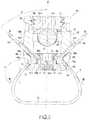
- FIG. 1is a perspective view of an example of bone fixing system according to the present disclosure
- FIG. 2is a partial perspective view of the bone fixing system of FIG. 1 ;
- FIG. 3is a sectional view of the bone fixing system of FIG. 1 , along the plane III-III;
- FIG. 4is a sectional view of another example of bone fixing system according to the present disclosure.
- FIG. 5is a perspective view of another example of bone fixing system according to the present disclosure.
- FIG. 6is a sectional view of the bone fixing system of FIG. 5 , along the plane VI-VI;
- FIG. 7is a sectional view of another example of bone fixing system according to the present disclosure.
- FIG. 8is a sectional view of another example of bone fixing system according to the present disclosure.
- FIG. 9is a sectional view of another example of bone fixing system according to the present disclosure.
- FIG. 10is a sectional view of the bone fixing system of FIG. 9 ; along the plane X-X;
- FIG. 11is a sectional view of another example of bone fixing system according to the present disclosure.
- FIG. 12is a sectional view of the one fixing system of FIG. 11 , along the plane XII-XII;
- FIG. 13is a sectional view of another example of bone fixing system according to the present disclosure.
- FIG. 14is a sectional view of another embodiment of the compression member of the bone fixing system.
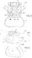
- FIG. 15is a view showing the bone fixing system of FIG. 1 put into place on a vertebra.
- FIG. 16is a view showing the bone fixing system of FIG. 1 fitted with the compression member of FIG. 14 and put into place on a vertebra.
- the bone fixing system 10is for fixing a rod 5 (a portion of which is shown in FIGS. 1, 3 and 15 ) to a bone (see FIG. 15 ).
- the bonemay be, for instance, a lamina of a vertebra or a transverse process TP of a vertebra V, as shown in FIG. 15 .
- the bone fixing system 10comprises
- a conformable elongate member 7such as a ligature, having a first free end portion 7 a , a second free end portion 7 b , and an intermediate portion 7 c therebetween, said intermediate portion 7 c being adapted to surround the bone e.g. the transverse process TP);
- main body 12a main body 12 ;
- first fastening deviceor means for fastening a portion of the rod 5 to the main body 12 ;
- second fastening deviceor means for fastening the free end portions 7 a , 7 b of the elongate member 7 to the main body 12 , said second fastening means being distinct from the first fastening means.
- the elongate member 7may be any suitable material that is conformable such as a band, wire, or cord made of metal, a polymeric material, or a combination of the two.
- the second fastening meanscomprise a compression member 14 which is movable relative to the main body 12 , the compression member 14 and the main body 12 both defining clamping surfaces 14 c , 12 c , between which the free end portions 7 a , 7 b of the elongate member 7 may be inserted, said free end portions 7 a , 7 b being clamped between said clamping surfaces 12 c , 14 c by moving the compression member 14 relative to the main body 12 .
- the main body 12is hollow, extends along a first axis Z from its lower end to its upper end, and comprises:
- a bottom part 12 blocated under the main part 12 a and provided with a second internal passage 22 extending through the entire thickness of the bottom part 12 b and communicating with the first internal passage 20 .
- the main body 12further comprises third and fourth internal passages 43 , 44 through which the first and second free end portions 7 a , 7 b of the elongate member 7 may be inserted respectively.
- Each internal passage 43 ( 44 )extends through the main body 12 , has two ends 4 43 b ( 44 a , 44 b ) and opens, at one end 43 a ( 44 a ), in front of the compression member 14 and, at the other end 43 b ( 44 b ), onto an outer face of the main body and, more precisely, onto a side face of the main body 12 .
- the third and fourth internal passages 43 , 44form guiding means for the free end portions 7 a , 7 b of the elongate member 7 .
- the third and fourth internal passages 43 , 44extend, respectively, along third and fourth axis A, A′, each of the third and fourth axis forming with respect to said first axis Z an acute angle C which is preferably comprised between 0 and 70.degree.
- an acute angle Cwhich is preferably comprised between 0 and 70.degree.
- the clamping surfaces 14 c , 12 c of the compression member 14 and of the main body 12define between them fifth and sixth passages 53 , 54 extending, respectively, along fifth and sixth axis B, B′, each of the fifth and sixth axis forming with respect to said first axis Z an obtuse angle D.
- the compression member 14is provided with a threaded hole 24 .
- Said locking mechanismcomprises a first screw 26 having a head 26 a and a shaft 26 b with an external thread.
- the screw shaft 26 bpasses through the second internal passage 22 and the screw head 26 a has a profile 28 that allows the first screw 26 to be driven.
- the screw head 26 ais a socket head and, more particularly, a hex socket head which can be driven, for instance, by an Allen key.
- openings 30are provided in the side walls 13 (see FIG. 2 ), so that a portion of the rod 5 may be loaded into the main body 12 via said openings 30 , and a closure member 32 engages with the main body 12 so as to secure said portion of rod 5 to the main body.
- the main body 12is provided with a first thread 13 b for engagement with a second thread 32 a provided on the closure member 32 , so that said portion of rod 5 may be clamped between the main body 12 and the closure member by threadably moving the closure member 32 relative to the main body 12 . More precisely, in the example, the rod portion is clamped between the edges 13 a of the side walls 13 delimiting the bottom of the openings 30 , and the lower face of the closure member 32 .
- the closure member 32has an external thread 32 a engaging with an internal thread 13 b provided on the inner face of the side walls 13 .
- the closure member 32further comprises a socket head 32 b for driving it in rotation.
- FIG. 4Another example of bone fixing system is shown on FIG. 4 .
- the bone fixing system 110 of FIG. 4differs from that of FIG. 3 by the locking mechanism.
- the second internal passage 22 of the bottom part 12 bis provided with an internal thread 123
- the compression member 114has a protruding part 114 a forming said locking mechanism.
- Said protruding part 114 aextends upwardly, has on its upper end a profile 128 that allows the compression member 114 to be driven in rotation, and is provided with an external thread 114 b engaging with said internal thread 123 .
- the bottom part 12 b of the main body 12is integral with the main part 12 a of the main body 12 . This is not the case in the examples of FIGS. 5-7 .
- FIGS. 5 and 6show another example of bone fixing system 210 differing from that of FIGS. 1-3 in that it comprises a main body 112 with a bottom part 212 b and a main part 212 a which are not integral with each other.
- the bottom part 212 b and the main part 212 a of the main body 212are interconnected by a ball-and-socket connection.
- the main part 212 acomprises a bottom wall 250 , the bottom wall 250 being provided with a through hole 251 delimited by an upper edge 251 a .
- the ball-and-socket type connectioncomprises a second screw 252 having a head 252 a and a shaft 252 b .
- the screw shaft 252 bpasses through said through hole 251 and through the second internal passage 222 .
- the screw head 252 ahas a convex lower face 252 c bearing on said upper edge 251 a , and a profile that allows the second screw 252 to be driven.
- the screw head 252 amay be a hex-head or a socket-head.
- the screw head 252 afurther has a concave upper face 252 d.
- the rod 5leans against the concave upper face 252 d of the second screw 252 . More precisely, when the closure member 32 is screwed down, the closure member 32 pushes down on the rod 5 which in turn pushes down on the screw 252 until the convex lower face 252 c of the screw head 252 a leans against the upper edge 251 a of the through hole 251 . Since the contact zones between the screw head 252 a and the upper edge 251 a and between the screw head 252 a and the rod 5 , are limited, the screw head 252 a is able to move with respect to the he main part 212 a of the main body 212 .
- the above structureis one example of a ball-and-socket type connection but other examples could be used.
- a ball-and-socket type connectionallows a limited amount of relative movement between the bottom part 212 b and the main part 212 a of the main body 212 and, thus, between the bone and the rod 5 , thereby providing or improving the desired dynamic stabilizing effect.
- the bottom part 212 bis substantially the same as the bottom part 12 b of FIG. 3 except for the screw head 226 a which has an outer driving profile 228 (instead of the inner driving profile 28 ), and apart from the fact that the screw 226 is provided with an internal threaded hole 227 .
- the screw shaft 252 bwhich has an external thread, passes through the second internal passage 222 and engages with the threaded hole 227 , so as to connect together the bottom part 212 b and the main part 212 a of the main body 212 .
- FIG. 7Another example of bone fixing system 310 with a ball-and-socket type connection is shown on FIG. 7 .
- the main part 312 a of the main body 312 and the second screw 352are the same as those ( 212 a , 252 ) of FIG. 6
- the bottom part 312 b of the main body 312is substantially the same as the bottom part 12 b of FIG. 4 apart from the fact that the protruding part 314 a of the compression member 314 has an outer driving profile 328 instead of the inner driving profile 128 , and that the compression member 314 is provided with an internal threaded hole 327 .
- the screw shaft 352 bwhich has an external thread, passes through the second internal passage 322 and engages with the threaded hole 327 , so as to connect together the bottom part 312 b and the main part 312 a of the main body 312 .
- the screw shaft 252 b , 352 bpasses through the through hole 251 , 351 of the bottom wall 250 , 350 of the main part 212 a , 312 a and through the second internal passage 222 , 322 and engages with the compression member 214 , 314 .
- itengages directly with the compression member 314
- FIG. 6it engages indirectly with the compression member 214 , via the screw 226 .
- FIGS. 8 to 13Other examples of bone fixing systems 410 , 510 , 610 , 710 , for fixing a bone to a rod 5 , are shown on FIGS. 8 to 13 . Each of them comprises:
- a conformable elongate member 7having a first free end portion 7 a , a second free end portion 7 b , and an intermediate portion 7 c therebetween, said intermediate portion 7 c being adapted to surround said bone;
- first fastening deviceor means for fastening a portion of the rod 5 to main body 412 , 512 , 612 , 712 ;
- the first fastening device or means for fastening a portion of the rod 5 to the main body 412 , 512 , 612are the same as those of FIGS. 1-4 and, therefore, do not need to be described again.
- the second fastening meanscomprise a compression member which is movable relative to the main body 412 , 512 , 612 , the compression member and the main body both defining clamping surfaces between which the free end portions 7 a , 7 b of the elongate member 7 may be inserted, said free end portions being clamped between said clamping surfaces by moving the compression member relative to the main body.
- the compression member 414is provided with a thread 414 d for rotative engagement with another thread 412 a provided on the main body 412 , so that the free end portions 7 a , 7 b of the elongate member 7 may be clamped between a compression part 412 e of the main body 412 and the compression member 414 by threadably moving the compression member 414 relative to the main body 412 .
- the compression member 414is a nut provided with an internal thread 414 d
- the main body 412is provided with an external thread 412 a .
- the main body 412comprises:
- a compression part 41which is a flange protruding on the lateral faces of the main body 412 , and
- each of the third and fourth internal passages 453 , 454extending through the main body, having two ends and opening, at one end, in front of the compression member 414 and, at the other end, onto an outer face of the main body 412 and, more precisely, onto the end face of the main body 412 which is opposite to the other end face receiving the rod 5 .
- the compression member 514is also a nut provided with an internal thread 514 d (see FIG. 10 ), and the main body 512 is also provided with an external thread 512 a , but in this case, the compression member 514 is not in direct contact with the elongate member 7 . Indeed, the compression member 514 cooperates with two profiled rotating pieces 515 which are rotatably mounted (around the axis in recesses 512 i provided on the lateral faces of the main body 512 .
- each free end portion 7 a , 7 b of the elongate memberis clamped between a rotating piece 515 and the bottom wall of the recess 512 i.
- the compression member 614is a circlip and the main body has a peripheral groove 612 i for receiving the free end portions 7 a , 7 b of the elongate member and the compression member 614 .
- the free end portions 7 a , 7 bare inserted and clamped between the bottom of the groove 612 i and the compression member 614 .
- the compression member 614could also be a fastening collar.
- the peripheral groove 612 imay extend along the entire circumference of the main body 612 , or along a part of it.
- the second fastening device or meanscomprise a screw 764 and a compression member 714 which is provided with a through hole 760 .
- the main body 712 of the bone fixing system 710is provided with a threaded hole 762 aligned with said through hole 760 .
- the shaft 764 b of the screw 764passes through said through hole 760 and is threadably engaged with the threaded hole 762 .
- the head 764 a of the screw 764is intended to lean against the upper surface of the compression member 714 .
- the compression member 714 and the main body 712both define clamping surfaces between which the free end portions 7 a , 7 b of the elongate member may be inserted and clamped, said free end portions being clamped by screwing the screw 764 into the main body 712 .
- the first fastening device or meanscomprise a seat part 766 for receiving a portion of the rod 5 , the seat part 766 facing the intermediate portion 7 c of the elongate member 7 , said portion of rod 5 being clamped between the seat part 766 and the intermediate portion 7 c of the elongate member by tightening the elongate member 7 (i.e. by pulling on the free end portions 7 a , 7 b of the elongate member 7 ).
- the seat part 766is a clip for holding the rod 5 .
- the seat part 766is delimited by two open arms 763 with certain elasticity, said arms 763 partially surrounding the rod 5 .
- FIG. 15the bone fixing system 10 of FIGS. 1-3 is shown in a tightened position around a vertebra V. More precisely, the intermediate portion 7 c of the elongate member 7 surrounds the transverse process TP of the vertebra.
- the compression member 14may be made in a soft material, order to avoid damaging the vertebra V and/or to allow a limited amount of relative movement between the vertebra V and the system 10 , and thus between the vertebra V and the rod 5 , thereby providing a dynamic stabilization effect, More particularly, compared to the material which makes up the main body 12 and which is preferably rigid, the material the compression member 14 is softer.
- the compression member 14 ′may be provided with at least one peripheral groove 19 ′ on its side faces.
- Such a peripheral groove 19 ′makes the deformation of the compression member 14 ′ easier and allows the member 14 ′ to bend laterally and to compress axially.
- a limited amount of relative movement (including pivoting movement) between the vertebra. V and the system 10is allowed, as illustrated by the double arrow P on FIG. 16 .
Landscapes
- Health & Medical Sciences (AREA)
- Orthopedic Medicine & Surgery (AREA)
- Life Sciences & Earth Sciences (AREA)
- Surgery (AREA)
- Neurology (AREA)
- Heart & Thoracic Surgery (AREA)
- Engineering & Computer Science (AREA)
- Biomedical Technology (AREA)
- Nuclear Medicine, Radiotherapy & Molecular Imaging (AREA)
- Medical Informatics (AREA)
- Molecular Biology (AREA)
- Animal Behavior & Ethology (AREA)
- General Health & Medical Sciences (AREA)
- Public Health (AREA)
- Veterinary Medicine (AREA)
- Surgical Instruments (AREA)
Abstract
Description
Claims (20)
Priority Applications (1)
| Application Number | Priority Date | Filing Date | Title |
|---|---|---|---|
| US15/826,940US10512486B2 (en) | 2009-07-31 | 2017-11-30 | Bone fixing system |
Applications Claiming Priority (8)
| Application Number | Priority Date | Filing Date | Title |
|---|---|---|---|
| EP09305720AEP2279707A1 (en) | 2009-07-31 | 2009-07-31 | Bone fixing system |
| EP09305720 | 2009-07-31 | ||
| EP09305720.6 | 2009-07-31 | ||
| PCT/EP2010/061085WO2011012690A1 (en) | 2009-07-31 | 2010-07-30 | Bone fixing system |
| US201213384180A | 2012-01-13 | 2012-01-13 | |
| US14/695,863US9668774B2 (en) | 2009-07-31 | 2015-04-24 | Bone fixing system |
| US15/591,904US9861391B2 (en) | 2009-07-31 | 2017-05-10 | Bone fixing system |
| US15/826,940US10512486B2 (en) | 2009-07-31 | 2017-11-30 | Bone fixing system |
Related Parent Applications (1)
| Application Number | Title | Priority Date | Filing Date |
|---|---|---|---|
| US15/591,904ContinuationUS9861391B2 (en) | 2009-07-31 | 2017-05-10 | Bone fixing system |
Publications (2)
| Publication Number | Publication Date |
|---|---|
| US20180078285A1 US20180078285A1 (en) | 2018-03-22 |
| US10512486B2true US10512486B2 (en) | 2019-12-24 |
Family
ID=41557586
Family Applications (4)
| Application Number | Title | Priority Date | Filing Date |
|---|---|---|---|
| US13/384,180Expired - Fee RelatedUS9039708B2 (en) | 2009-07-31 | 2010-07-30 | Bone fixing system |
| US14/695,863Active2030-10-14US9668774B2 (en) | 2009-07-31 | 2015-04-24 | Bone fixing system |
| US15/591,904ActiveUS9861391B2 (en) | 2009-07-31 | 2017-05-10 | Bone fixing system |
| US15/826,940Expired - Fee RelatedUS10512486B2 (en) | 2009-07-31 | 2017-11-30 | Bone fixing system |
Family Applications Before (3)
| Application Number | Title | Priority Date | Filing Date |
|---|---|---|---|
| US13/384,180Expired - Fee RelatedUS9039708B2 (en) | 2009-07-31 | 2010-07-30 | Bone fixing system |
| US14/695,863Active2030-10-14US9668774B2 (en) | 2009-07-31 | 2015-04-24 | Bone fixing system |
| US15/591,904ActiveUS9861391B2 (en) | 2009-07-31 | 2017-05-10 | Bone fixing system |
Country Status (4)
| Country | Link |
|---|---|
| US (4) | US9039708B2 (en) |
| EP (3) | EP2279707A1 (en) |
| CN (1) | CN202821564U (en) |
| WO (1) | WO2011012690A1 (en) |
Cited By (5)
| Publication number | Priority date | Publication date | Assignee | Title |
|---|---|---|---|---|
| US11207107B2 (en) | 2017-07-31 | 2021-12-28 | Medos International Sarl | Systems and methods for reducing the risk of proximal junctional kyphosis using a bone anchor or other attachment point |
| US11298158B2 (en) | 2017-07-31 | 2022-04-12 | Medos International Sarl | Connectors for use in systems and methods for reducing the risk of proximal junctional kyphosis |
| US11771475B2 (en) | 2020-10-07 | 2023-10-03 | Globus Medical, Inc. | Systems and methods for surgical procedures using band clamp implants and tensioning instruments |
| US11974785B2 (en) | 2020-10-16 | 2024-05-07 | Globus Medical, Inc | Band clamp implants |
| US12213706B2 (en) | 2020-10-07 | 2025-02-04 | Globus Medical, Inc. | Systems and methods for surgical procedures using band clamp implants and tensioning instruments |
Families Citing this family (60)
| Publication number | Priority date | Publication date | Assignee | Title |
|---|---|---|---|---|
| FR2890850B1 (en) | 2005-09-20 | 2009-04-17 | Abbott Spine Sa | VERTEBRAL FASTENING SYSTEM |
| US8100946B2 (en) | 2005-11-21 | 2012-01-24 | Synthes Usa, Llc | Polyaxial bone anchors with increased angulation |
| WO2007121271A2 (en) | 2006-04-11 | 2007-10-25 | Synthes (U.S.A) | Minimally invasive fixation system |
| EP2047813A1 (en)* | 2007-10-11 | 2009-04-15 | Abbott Spine | Bone fixing system and method of use |
| CA2694010C (en) | 2007-07-19 | 2015-04-21 | Synthes Usa, Llc | Clamps used for interconnecting a bone anchor to a rod |
| US9439681B2 (en) | 2007-07-20 | 2016-09-13 | DePuy Synthes Products, Inc. | Polyaxial bone fixation element |
| WO2010014119A1 (en) | 2008-07-29 | 2010-02-04 | Synthes (U.S.A) | Crimp with an insert to hold a cable |
| JP5815407B2 (en) | 2008-09-12 | 2015-11-17 | ジンテス ゲゼルシャフト ミット ベシュレンクテル ハフツング | Spinal stabilization and guided fixation system |
| KR20110081208A (en) | 2008-09-29 | 2011-07-13 | 신세스 게엠바하 | Multi-Axis Bottom-Loading Screw and Rod Assemblies |
| CA2742399A1 (en) | 2008-11-03 | 2010-06-03 | Dustin M. Harvey | Uni-planar bone fixation assembly |
| KR20120013312A (en) | 2009-04-15 | 2012-02-14 | 신세스 게엠바하 | Orthodontic Connectors for Spinal Structures |
| CN102497828B (en) | 2009-05-20 | 2015-09-09 | 斯恩蒂斯有限公司 | What patient installed retracts part |
| CA2764841A1 (en) | 2009-06-17 | 2010-12-23 | Synthes Usa, Llc | Revision connector for spinal constructs |
| EP2279707A1 (en) | 2009-07-31 | 2011-02-02 | Zimmer Spine | Bone fixing system |
| EP2316363A1 (en) | 2009-10-27 | 2011-05-04 | Zimmer Spine | Bone holding device |
| US8535318B2 (en) | 2010-04-23 | 2013-09-17 | DePuy Synthes Products, LLC | Minimally invasive instrument set, devices and related methods |
| EP2422728B1 (en) | 2010-08-25 | 2013-01-30 | Zimmer Spine | Anchor for attachment to a bony structure |
| CN103717159B (en) | 2011-05-27 | 2016-08-17 | 新特斯有限责任公司 | Minimally Invasive Spinal Fixation System Including Vertebral Alignment Features |
| FR2976783B1 (en) | 2011-06-22 | 2014-05-09 | Medicrea International | MATERIAL OF VERTEBRAL OSTEOSYNTHESIS |
| WO2013003719A1 (en) | 2011-06-29 | 2013-01-03 | Biomet Microfixation, Llc | Locking mechanism to secure ends of an implantable fabric |
| EP2734135B1 (en) | 2011-07-21 | 2018-03-21 | Zimmer Spine | Spinal rod fixing device |
| US8636770B2 (en) | 2011-08-08 | 2014-01-28 | Zimmer Spine, Inc. | Bone anchoring device |
| WO2013040456A1 (en)* | 2011-09-14 | 2013-03-21 | Band-Lok, Llc | Tether clamp and implantation system |
| US8834523B2 (en)* | 2011-09-29 | 2014-09-16 | Smith & Nephew, Inc. | Attachment device to attach tissue graft |
| EP2747670A4 (en) | 2011-10-05 | 2015-06-24 | Mark A Dodson | Modular retractor and related method |
| EP2819646A4 (en)* | 2012-02-03 | 2015-09-23 | Ardavan Aslie | Spinal fusion system for osteoporotic vertebrae |
| FR2988992B1 (en)* | 2012-04-04 | 2015-03-20 | Medicrea International | MATERIAL OF VERTEBRAL OSTEOSYNTHESIS |
| EP2668921B1 (en)* | 2012-06-01 | 2015-08-12 | Zimmer Spine | Device for fixing a bony structure to a support member |
| US9642719B1 (en) | 2012-11-07 | 2017-05-09 | Costello Law Corporation | Spinal fusion system for osteoporotic vertebrae |
| US20140148854A1 (en) | 2012-11-28 | 2014-05-29 | Zimmer Spine, Inc. | Vertebral fixation system |
| EP2762095B1 (en) | 2013-01-31 | 2016-05-25 | Zimmer Spine | Device for fixing a bony structure to a support member |
| US10034692B2 (en)* | 2013-03-05 | 2018-07-31 | Globus Medical, Inc. | Elastic member clamps |
| US9675386B2 (en) | 2013-03-11 | 2017-06-13 | K2M, Inc. | Flexible fastening system |
| US10010359B2 (en) | 2013-03-15 | 2018-07-03 | Zimmer Biomet CMF and Thoracic, LLC | Sternal closure cerclage, plate implant and instrumentation |
| WO2014144479A1 (en) | 2013-03-15 | 2014-09-18 | Biomet Microfixation, Llc | Sternal closure cerclage, plate implant and instrumentation |
| US9820755B2 (en) | 2013-03-15 | 2017-11-21 | Zimmer Biomet CMF and Thoracic, LLC | Sternal closure cerclage, plate implant and instrumentation |
| FR3008305B1 (en)* | 2013-07-15 | 2015-08-07 | Cousin Biotech | IMPLANTABLE DEVICE, IN PARTICULAR FOR CORRECTING AT LEAST ONE VERTEBRAL LEVEL |
| US9693809B2 (en)* | 2014-03-20 | 2017-07-04 | Warsaw Orthopedic, Inc. | Spinal correction implant system and method |
| US9402666B2 (en)* | 2014-04-30 | 2016-08-02 | King Faisal Specialist Hospital & Research Centre | Vertebral fixation device |
| FR3035584B1 (en)* | 2015-04-29 | 2017-05-19 | Medicrea Int | MATERIAL OF VERTEBRAL OSTEOSYNTHESIS |
| US9924976B2 (en) | 2015-09-24 | 2018-03-27 | Warsaw Orthopedic, Inc. | Spinal implant system and method |
| FR3047657B1 (en)* | 2016-02-15 | 2018-02-09 | Backbone | INTERVERTEBRAL IMPLANT OF DYNAMIC STABILIZATION AND SURGICAL KIT INCORPORATING IT |
| US10874438B2 (en)* | 2016-07-13 | 2020-12-29 | Medos International Sarl | Bone anchor assemblies and related instrumentation |
| EP3490474A4 (en)* | 2016-07-26 | 2019-08-28 | Band-lok, LLC | ORTHOPEDIC IMPLANTS. |
| EP3525699B1 (en) | 2016-10-11 | 2023-07-26 | K2M, Inc. | Spinal implant |
| CN106491199A (en)* | 2016-10-27 | 2017-03-15 | 贾东林 | A kind of Orthopedic fixation device |
| US10307186B2 (en) | 2016-12-02 | 2019-06-04 | Nuvasive, Inc. | Surgical band clamp system |
| US11051857B2 (en)* | 2017-08-10 | 2021-07-06 | Ortho Development Corporation | Tether clamping assemblies and related methods and apparatus |
| US11071569B2 (en) | 2017-08-10 | 2021-07-27 | Ortho Development Corporation | Nesting tether clamping assemblies and related methods and apparatus |
| EP3806762B1 (en)* | 2018-06-05 | 2024-05-22 | K2M, Inc. | Band clamp, band clamp assembly |
| CN109009385A (en)* | 2018-08-12 | 2018-12-18 | 苏州爱得科技发展股份有限公司 | A kind of dynamic state screw |
| CN109394322B (en)* | 2018-10-18 | 2020-10-27 | 温州医科大学附属第二医院、温州医科大学附属育英儿童医院 | An extensible spinal internal fixation device for laterally fixing the bone position |
| US10568674B1 (en) | 2019-01-24 | 2020-02-25 | Syberspine Limited | Pedicle screws with integrated anchor for retaining artificial ligament tape used for posterior ligament reconstruction |
| WO2020159483A1 (en)* | 2019-01-29 | 2020-08-06 | Ortho Development Corporation | Tether clamping assemblies and related methods and apparatus |
| US10869696B2 (en)* | 2019-01-30 | 2020-12-22 | Medos International Sarl | Surgical device for spinal fixation |
| US11819255B2 (en) | 2019-10-07 | 2023-11-21 | Ortho Development Corporation | Tether tensioning instrumentation and related methods |
| US20210121203A1 (en)* | 2019-10-29 | 2021-04-29 | Globus Medical, Inc. | Sublaminar band clamp |
| CN112022318B (en)* | 2020-09-22 | 2022-05-13 | 常州集硕医疗器械有限公司 | Spinal deformity growth fixing system and method |
| US12433644B2 (en) | 2022-11-17 | 2025-10-07 | Warsaw Orthopedic, Inc. | Multiaxial receivers with tether |
| US11877775B1 (en) | 2022-11-21 | 2024-01-23 | Warsaw Orthopedic, Inc. | Multiaxial receivers with tether |
Citations (36)
| Publication number | Priority date | Publication date | Assignee | Title |
|---|---|---|---|---|
| US2049361A (en) | 1934-10-27 | 1936-07-28 | Ericsson Ernst Axel Johan | Wire or ribbon tightening apparatus |
| US4570618A (en) | 1983-11-23 | 1986-02-18 | Henry Ford Hospital | Intervertebral body wire stabilization |
| US5030220A (en) | 1990-03-29 | 1991-07-09 | Advanced Spine Fixation Systems Incorporated | Spine fixation system |
| WO1993003681A1 (en) | 1991-08-27 | 1993-03-04 | Howmedica Inc. | Cerclage wire positioning insert |
| WO1993005720A1 (en) | 1991-09-20 | 1993-04-01 | Milres Corporation | Surgical cutting tool |
| US5242446A (en)* | 1992-01-02 | 1993-09-07 | Acromed Corporation | Connector for a spinal column corrective device |
| US5304178A (en) | 1992-05-29 | 1994-04-19 | Acromed Corporation | Sublaminar wire |
| US5772663A (en) | 1994-02-17 | 1998-06-30 | Whiteside; Leo A. | Surgical device for banding bone with cable |
| USRE36221E (en) | 1989-02-03 | 1999-06-01 | Breard; Francis Henri | Flexible inter-vertebral stabilizer as well as process and apparatus for determining or verifying its tension before installation on the spinal column |
| US5935133A (en) | 1997-08-26 | 1999-08-10 | Spinal Concepts, Inc. | Surgical cable system and method |
| US6053921A (en) | 1997-08-26 | 2000-04-25 | Spinal Concepts, Inc. | Surgical cable system and method |
| US6086590A (en) | 1999-02-02 | 2000-07-11 | Pioneer Laboratories, Inc. | Cable connector for orthopaedic rod |
| US6179838B1 (en) | 1998-02-24 | 2001-01-30 | Daniel Fiz | Bone fixation arrangements and method |
| WO2001054599A1 (en) | 2000-01-31 | 2001-08-02 | Sven Olerud | Locking device and method for using this device |
| US6277120B1 (en) | 2000-09-20 | 2001-08-21 | Kevin Jon Lawson | Cable-anchor system for spinal fixation |
| US6299613B1 (en) | 1999-04-23 | 2001-10-09 | Sdgi Holdings, Inc. | Method for the correction of spinal deformities through vertebral body tethering without fusion |
| US6309390B1 (en) | 1997-04-04 | 2001-10-30 | Stryker France S.A. | Device for backbone osteosynthesis with offset intervertebral fixing rod |
| EP1205152A1 (en) | 2000-11-10 | 2002-05-15 | Lafitt, S.A. | Spinal column deformity correction procedure and device for putting it into practice |
| US20020116013A1 (en) | 2000-10-24 | 2002-08-22 | Gleason Joseph E. | Tension band clip |
| US6514255B1 (en) | 2000-02-25 | 2003-02-04 | Bret Ferree | Sublaminar spinal fixation apparatus |
| US6547790B2 (en) | 2000-08-08 | 2003-04-15 | Depuy Acromed, Inc. | Orthopaedic rod/plate locking mechanisms and surgical methods |
| US6605091B1 (en) | 2000-06-30 | 2003-08-12 | Pioneer Laboratories, Inc. | Surgical cable assembly and method |
| US6695852B2 (en) | 2001-10-31 | 2004-02-24 | Spineology, Inc. | Tension tools for tension band clip |
| WO2006106268A2 (en) | 2005-04-07 | 2006-10-12 | Abbott Spine | Intervertebral implant for lumbrosacral joint |
| US20060276789A1 (en)* | 2005-05-27 | 2006-12-07 | Jackson Roger P | Polyaxial bone screw with shank articulation pressure insert and method |
| US20070191844A1 (en) | 2006-01-31 | 2007-08-16 | Sdgi Holdings, Inc. | In-series, dual locking mechanism device |
| US7481828B2 (en) | 2002-07-23 | 2009-01-27 | Abbott Spine, Inc. | Vertebral fixing system |
| US20090138048A1 (en) | 2005-09-21 | 2009-05-28 | Abbott Laboratories | Instrument for tensioning a flexible tie |
| US20090192548A1 (en)* | 2008-01-25 | 2009-07-30 | Jeon Dong M | Pedicle-laminar dynamic spinal stabilization device |
| US20090248077A1 (en) | 2008-03-31 | 2009-10-01 | Derrick William Johns | Hybrid dynamic stabilization |
| US20090326585A1 (en) | 2005-09-20 | 2009-12-31 | Abbott Spine | Vertebral fixing system |
| US20100249845A1 (en) | 2007-10-23 | 2010-09-30 | Alain Meunier | Fixing devices and stabilization systems using said fixing devices |
| US20110112581A1 (en) | 2008-05-27 | 2011-05-12 | Medicrea International | Vertebral osteosynthesis equipment |
| US20120022592A1 (en) | 2007-10-11 | 2012-01-26 | Karl Pierre Belliard | Bone fixing system and method of use |
| US8128635B2 (en) | 2007-10-23 | 2012-03-06 | Zimmer Spine S.A.S. | Bone fixation tensioning tool and method |
| US20120130373A1 (en) | 2009-07-31 | 2012-05-24 | Gilles Larroque-Lahitette | Bone fixing system |
Family Cites Families (4)
| Publication number | Priority date | Publication date | Assignee | Title |
|---|---|---|---|---|
| US4269178A (en) | 1979-06-04 | 1981-05-26 | Keene James S | Hook assembly for engaging a spinal column |
| GB0018826D0 (en) | 2000-08-02 | 2000-09-20 | Depuy Int Ltd | Improvements in and relating to fixings |
| FR2845269B1 (en) | 2002-10-07 | 2005-06-24 | Spine Next Sa | PLATE FASTENING SYSTEM |
| FR2859376B1 (en) | 2003-09-04 | 2006-05-19 | Spine Next Sa | SPINAL IMPLANT |
- 2009
- 2009-07-31EPEP09305720Apatent/EP2279707A1/ennot_activeWithdrawn
- 2010
- 2010-07-30CNCN2010900010422Upatent/CN202821564U/ennot_activeExpired - Fee Related
- 2010-07-30EPEP10736744.3Apatent/EP2459087B1/ennot_activeNot-in-force
- 2010-07-30EPEP15174582.5Apatent/EP3045128B1/ennot_activeNot-in-force
- 2010-07-30WOPCT/EP2010/061085patent/WO2011012690A1/enactiveApplication Filing
- 2010-07-30USUS13/384,180patent/US9039708B2/ennot_activeExpired - Fee Related
- 2015
- 2015-04-24USUS14/695,863patent/US9668774B2/enactiveActive
- 2017
- 2017-05-10USUS15/591,904patent/US9861391B2/enactiveActive
- 2017-11-30USUS15/826,940patent/US10512486B2/ennot_activeExpired - Fee Related
Patent Citations (50)
| Publication number | Priority date | Publication date | Assignee | Title |
|---|---|---|---|---|
| US2049361A (en) | 1934-10-27 | 1936-07-28 | Ericsson Ernst Axel Johan | Wire or ribbon tightening apparatus |
| US4570618A (en) | 1983-11-23 | 1986-02-18 | Henry Ford Hospital | Intervertebral body wire stabilization |
| USRE36221E (en) | 1989-02-03 | 1999-06-01 | Breard; Francis Henri | Flexible inter-vertebral stabilizer as well as process and apparatus for determining or verifying its tension before installation on the spinal column |
| US5030220A (en) | 1990-03-29 | 1991-07-09 | Advanced Spine Fixation Systems Incorporated | Spine fixation system |
| WO1993003681A1 (en) | 1991-08-27 | 1993-03-04 | Howmedica Inc. | Cerclage wire positioning insert |
| WO1993005720A1 (en) | 1991-09-20 | 1993-04-01 | Milres Corporation | Surgical cutting tool |
| US5242446A (en)* | 1992-01-02 | 1993-09-07 | Acromed Corporation | Connector for a spinal column corrective device |
| US5304178A (en) | 1992-05-29 | 1994-04-19 | Acromed Corporation | Sublaminar wire |
| US5772663A (en) | 1994-02-17 | 1998-06-30 | Whiteside; Leo A. | Surgical device for banding bone with cable |
| US6309390B1 (en) | 1997-04-04 | 2001-10-30 | Stryker France S.A. | Device for backbone osteosynthesis with offset intervertebral fixing rod |
| US5964769A (en) | 1997-08-26 | 1999-10-12 | Spinal Concepts, Inc. | Surgical cable system and method |
| US6053921A (en) | 1997-08-26 | 2000-04-25 | Spinal Concepts, Inc. | Surgical cable system and method |
| US6682533B1 (en) | 1997-08-26 | 2004-01-27 | Spinal Concepts, Inc. | Surgical cable system and method |
| US5935133A (en) | 1997-08-26 | 1999-08-10 | Spinal Concepts, Inc. | Surgical cable system and method |
| US6391030B1 (en) | 1997-08-26 | 2002-05-21 | Spinal Concepts, Inc. | Surgical cable system and method |
| US6179838B1 (en) | 1998-02-24 | 2001-01-30 | Daniel Fiz | Bone fixation arrangements and method |
| US6086590A (en) | 1999-02-02 | 2000-07-11 | Pioneer Laboratories, Inc. | Cable connector for orthopaedic rod |
| US6299613B1 (en) | 1999-04-23 | 2001-10-09 | Sdgi Holdings, Inc. | Method for the correction of spinal deformities through vertebral body tethering without fusion |
| WO2001054599A1 (en) | 2000-01-31 | 2001-08-02 | Sven Olerud | Locking device and method for using this device |
| US6514255B1 (en) | 2000-02-25 | 2003-02-04 | Bret Ferree | Sublaminar spinal fixation apparatus |
| US6605091B1 (en) | 2000-06-30 | 2003-08-12 | Pioneer Laboratories, Inc. | Surgical cable assembly and method |
| US6547790B2 (en) | 2000-08-08 | 2003-04-15 | Depuy Acromed, Inc. | Orthopaedic rod/plate locking mechanisms and surgical methods |
| US6277120B1 (en) | 2000-09-20 | 2001-08-21 | Kevin Jon Lawson | Cable-anchor system for spinal fixation |
| US20020116013A1 (en) | 2000-10-24 | 2002-08-22 | Gleason Joseph E. | Tension band clip |
| EP1205152A1 (en) | 2000-11-10 | 2002-05-15 | Lafitt, S.A. | Spinal column deformity correction procedure and device for putting it into practice |
| US6695852B2 (en) | 2001-10-31 | 2004-02-24 | Spineology, Inc. | Tension tools for tension band clip |
| US7481828B2 (en) | 2002-07-23 | 2009-01-27 | Abbott Spine, Inc. | Vertebral fixing system |
| US7959654B2 (en) | 2002-07-23 | 2011-06-14 | Zimmer Spine S.A.S. | Vertebral fixing system |
| US20110034956A1 (en) | 2002-07-23 | 2011-02-10 | Keyvan Mazda | Vertebral fixing system |
| WO2006106268A2 (en) | 2005-04-07 | 2006-10-12 | Abbott Spine | Intervertebral implant for lumbrosacral joint |
| US20060276789A1 (en)* | 2005-05-27 | 2006-12-07 | Jackson Roger P | Polyaxial bone screw with shank articulation pressure insert and method |
| US20120022591A1 (en) | 2005-09-20 | 2012-01-26 | Christian Baccelli | Vertebral fixing system |
| US20090326585A1 (en) | 2005-09-20 | 2009-12-31 | Abbott Spine | Vertebral fixing system |
| US20090138048A1 (en) | 2005-09-21 | 2009-05-28 | Abbott Laboratories | Instrument for tensioning a flexible tie |
| US20090182379A1 (en) | 2005-09-21 | 2009-07-16 | Abbott Spine | Flexible tie fastening system |
| US20110238125A1 (en) | 2005-09-21 | 2011-09-29 | Zimmer Spine S.A.S. | Method and instrument for tensioning a flexible tie |
| US20110238118A1 (en) | 2005-09-21 | 2011-09-29 | Zimmer Spine S.A.S. | Spinal implant with flexible tie |
| US20070191844A1 (en) | 2006-01-31 | 2007-08-16 | Sdgi Holdings, Inc. | In-series, dual locking mechanism device |
| US20120022592A1 (en) | 2007-10-11 | 2012-01-26 | Karl Pierre Belliard | Bone fixing system and method of use |
| US20120059377A1 (en) | 2007-10-11 | 2012-03-08 | Karl Pierre Belliard | Bone fixing system and method of use |
| US20100249845A1 (en) | 2007-10-23 | 2010-09-30 | Alain Meunier | Fixing devices and stabilization systems using said fixing devices |
| US8128635B2 (en) | 2007-10-23 | 2012-03-06 | Zimmer Spine S.A.S. | Bone fixation tensioning tool and method |
| US20090192548A1 (en)* | 2008-01-25 | 2009-07-30 | Jeon Dong M | Pedicle-laminar dynamic spinal stabilization device |
| US20090248077A1 (en) | 2008-03-31 | 2009-10-01 | Derrick William Johns | Hybrid dynamic stabilization |
| US20110112581A1 (en) | 2008-05-27 | 2011-05-12 | Medicrea International | Vertebral osteosynthesis equipment |
| US20120130373A1 (en) | 2009-07-31 | 2012-05-24 | Gilles Larroque-Lahitette | Bone fixing system |
| US9039708B2 (en) | 2009-07-31 | 2015-05-26 | Zimmer Spine | Bone fixing system |
| US20150223845A1 (en) | 2009-07-31 | 2015-08-13 | Zimmer Spine | Bone fixing system |
| US9668774B2 (en) | 2009-07-31 | 2017-06-06 | Zimmer Spine | Bone fixing system |
| US20170238970A1 (en) | 2009-07-31 | 2017-08-24 | Zimmer Spine | Bone fixing system |
Non-Patent Citations (7)
Cited By (8)
| Publication number | Priority date | Publication date | Assignee | Title |
|---|---|---|---|---|
| US11207107B2 (en) | 2017-07-31 | 2021-12-28 | Medos International Sarl | Systems and methods for reducing the risk of proximal junctional kyphosis using a bone anchor or other attachment point |
| US11298158B2 (en) | 2017-07-31 | 2022-04-12 | Medos International Sarl | Connectors for use in systems and methods for reducing the risk of proximal junctional kyphosis |
| US12336740B2 (en) | 2017-07-31 | 2025-06-24 | Medos International Sárl | Systems and methods for reducing the risk of proximal junctional kyphosis using a bone anchor or other attachment point |
| US12349943B2 (en) | 2017-07-31 | 2025-07-08 | Medos International Sàrl | Connectors for use in systems and methods for reducing the risk of proximal junctional kyphosis |
| US11771475B2 (en) | 2020-10-07 | 2023-10-03 | Globus Medical, Inc. | Systems and methods for surgical procedures using band clamp implants and tensioning instruments |
| US12213706B2 (en) | 2020-10-07 | 2025-02-04 | Globus Medical, Inc. | Systems and methods for surgical procedures using band clamp implants and tensioning instruments |
| US11974785B2 (en) | 2020-10-16 | 2024-05-07 | Globus Medical, Inc | Band clamp implants |
| US12419671B2 (en) | 2020-10-16 | 2025-09-23 | Globus Medical Inc. | Band clamps implants |
Also Published As
| Publication number | Publication date |
|---|---|
| US9039708B2 (en) | 2015-05-26 |
| US20180078285A1 (en) | 2018-03-22 |
| US9861391B2 (en) | 2018-01-09 |
| EP2279707A1 (en) | 2011-02-02 |
| US20120130373A1 (en) | 2012-05-24 |
| CN202821564U (en) | 2013-03-27 |
| EP2459087A1 (en) | 2012-06-06 |
| WO2011012690A1 (en) | 2011-02-03 |
| EP3045128B1 (en) | 2017-11-29 |
| US9668774B2 (en) | 2017-06-06 |
| US20150223845A1 (en) | 2015-08-13 |
| US20170238970A1 (en) | 2017-08-24 |
| EP3045128A1 (en) | 2016-07-20 |
| EP2459087B1 (en) | 2015-07-29 |
Similar Documents
| Publication | Publication Date | Title |
|---|---|---|
| US10512486B2 (en) | Bone fixing system | |
| US10238433B2 (en) | Fixing device | |
| US8323319B2 (en) | Vertebral fixing system | |
| US9993274B2 (en) | Bone fixing system and method of use | |
| US8926668B2 (en) | Anchor for attachment to a bony structure | |
| US9427263B2 (en) | Device for fixing a bony structure to a support member | |
| US9901377B2 (en) | Device for fixing a bony structure to a support member | |
| KR20090009853A (en) | Connector device |
Legal Events
| Date | Code | Title | Description |
|---|---|---|---|
| FEPP | Fee payment procedure | Free format text:ENTITY STATUS SET TO UNDISCOUNTED (ORIGINAL EVENT CODE: BIG.); ENTITY STATUS OF PATENT OWNER: LARGE ENTITY | |
| STPP | Information on status: patent application and granting procedure in general | Free format text:DOCKETED NEW CASE - READY FOR EXAMINATION | |
| STPP | Information on status: patent application and granting procedure in general | Free format text:NOTICE OF ALLOWANCE MAILED -- APPLICATION RECEIVED IN OFFICE OF PUBLICATIONS | |
| STPP | Information on status: patent application and granting procedure in general | Free format text:PUBLICATIONS -- ISSUE FEE PAYMENT VERIFIED | |
| STCF | Information on status: patent grant | Free format text:PATENTED CASE | |
| FEPP | Fee payment procedure | Free format text:MAINTENANCE FEE REMINDER MAILED (ORIGINAL EVENT CODE: REM.); ENTITY STATUS OF PATENT OWNER: LARGE ENTITY | |
| LAPS | Lapse for failure to pay maintenance fees | Free format text:PATENT EXPIRED FOR FAILURE TO PAY MAINTENANCE FEES (ORIGINAL EVENT CODE: EXP.); ENTITY STATUS OF PATENT OWNER: LARGE ENTITY | |
| STCH | Information on status: patent discontinuation | Free format text:PATENT EXPIRED DUE TO NONPAYMENT OF MAINTENANCE FEES UNDER 37 CFR 1.362 | |
| FP | Lapsed due to failure to pay maintenance fee | Effective date:20231224 | |
| AS | Assignment | Owner name:ZIMMER SPINE, FRANCE Free format text:ASSIGNMENT OF ASSIGNORS INTEREST;ASSIGNOR:LARROQUE-LAHITETTE, GILLES;REEL/FRAME:066860/0854 Effective date:20120206 | |
| AS | Assignment | Owner name:LDR MEDICAL, S.A.S., FRANCE Free format text:MERGER;ASSIGNOR:ZIMMER SPINE, S.A.S.;REEL/FRAME:066893/0633 Effective date:20231220 Owner name:LDR MEDICAL, S.A.S., FRANCE Free format text:MERGER;ASSIGNOR:ZIMMER SPINE, S.A.S.;REEL/FRAME:066891/0144 Effective date:20231109 |