US10512392B2 - Segmented instrument having braking capabilities - Google Patents
Segmented instrument having braking capabilitiesDownload PDFInfo
- Publication number
- US10512392B2 US10512392B2US12/866,309US86630909AUS10512392B2US 10512392 B2US10512392 B2US 10512392B2US 86630909 AUS86630909 AUS 86630909AUS 10512392 B2US10512392 B2US 10512392B2
- Authority
- US
- United States
- Prior art keywords
- links
- instrument
- pair
- brake assembly
- segmented
- Prior art date
- Legal status (The legal status is an assumption and is not a legal conclusion. Google has not performed a legal analysis and makes no representation as to the accuracy of the status listed.)
- Active, expires
Links
Images


Classifications
- A—HUMAN NECESSITIES
- A61—MEDICAL OR VETERINARY SCIENCE; HYGIENE
- A61B—DIAGNOSIS; SURGERY; IDENTIFICATION
- A61B1/00—Instruments for performing medical examinations of the interior of cavities or tubes of the body by visual or photographical inspection, e.g. endoscopes; Illuminating arrangements therefor
- A61B1/005—Flexible endoscopes
- A61B1/0051—Flexible endoscopes with controlled bending of insertion part
- A61B1/0052—Constructional details of control elements, e.g. handles
- A61B1/0053—Constructional details of control elements, e.g. handles using distributed actuators, e.g. artificial muscles
- A—HUMAN NECESSITIES
- A61—MEDICAL OR VETERINARY SCIENCE; HYGIENE
- A61B—DIAGNOSIS; SURGERY; IDENTIFICATION
- A61B1/00—Instruments for performing medical examinations of the interior of cavities or tubes of the body by visual or photographical inspection, e.g. endoscopes; Illuminating arrangements therefor
- A61B1/005—Flexible endoscopes
- A61B1/0051—Flexible endoscopes with controlled bending of insertion part
- A61B1/0055—Constructional details of insertion parts, e.g. vertebral elements
- A—HUMAN NECESSITIES
- A61—MEDICAL OR VETERINARY SCIENCE; HYGIENE
- A61B—DIAGNOSIS; SURGERY; IDENTIFICATION
- A61B1/00—Instruments for performing medical examinations of the interior of cavities or tubes of the body by visual or photographical inspection, e.g. endoscopes; Illuminating arrangements therefor
- A61B1/005—Flexible endoscopes
- A61B1/0051—Flexible endoscopes with controlled bending of insertion part
- A61B1/0057—Constructional details of force transmission elements, e.g. control wires
- A—HUMAN NECESSITIES
- A61—MEDICAL OR VETERINARY SCIENCE; HYGIENE
- A61B—DIAGNOSIS; SURGERY; IDENTIFICATION
- A61B1/00—Instruments for performing medical examinations of the interior of cavities or tubes of the body by visual or photographical inspection, e.g. endoscopes; Illuminating arrangements therefor
- A61B1/005—Flexible endoscopes
- A61B1/008—Articulations
- A—HUMAN NECESSITIES
- A61—MEDICAL OR VETERINARY SCIENCE; HYGIENE
- A61B—DIAGNOSIS; SURGERY; IDENTIFICATION
- A61B1/00—Instruments for performing medical examinations of the interior of cavities or tubes of the body by visual or photographical inspection, e.g. endoscopes; Illuminating arrangements therefor
- A61B1/04—Instruments for performing medical examinations of the interior of cavities or tubes of the body by visual or photographical inspection, e.g. endoscopes; Illuminating arrangements therefor combined with photographic or television appliances
- A61B1/042—Instruments for performing medical examinations of the interior of cavities or tubes of the body by visual or photographical inspection, e.g. endoscopes; Illuminating arrangements therefor combined with photographic or television appliances characterised by a proximal camera, e.g. a CCD camera
- A—HUMAN NECESSITIES
- A61—MEDICAL OR VETERINARY SCIENCE; HYGIENE
- A61B—DIAGNOSIS; SURGERY; IDENTIFICATION
- A61B1/00—Instruments for performing medical examinations of the interior of cavities or tubes of the body by visual or photographical inspection, e.g. endoscopes; Illuminating arrangements therefor
- A61B1/273—Instruments for performing medical examinations of the interior of cavities or tubes of the body by visual or photographical inspection, e.g. endoscopes; Illuminating arrangements therefor for the upper alimentary canal, e.g. oesophagoscopes, gastroscopes
- A61B1/2736—Gastroscopes
- G—PHYSICS
- G02—OPTICS
- G02B—OPTICAL ELEMENTS, SYSTEMS OR APPARATUS
- G02B23/00—Telescopes, e.g. binoculars; Periscopes; Instruments for viewing the inside of hollow bodies; Viewfinders; Optical aiming or sighting devices
- G02B23/24—Instruments or systems for viewing the inside of hollow bodies, e.g. fibrescopes
- G02B23/2476—Non-optical details, e.g. housings, mountings, supports
Definitions
- Embodiments of the present inventionprovide articulating and lockable segmented instruments useful in perform surgical procedures in the body.
- the instruments described hereinmay articulate and then be locked into a desired configuration.
- Guide tubesmay be used to support instruments disposed within them. Many conventional guide tubes provide some form of locking capability. However, conventional guide tubes provide a single surface lock engagement when locking. Such locking configurations may provide locking forces up to a point but are generally limited in the amount of locking force that may be generated. Some emerging forms of surgery may benefit from guide tubes or controllable instruments with locking or braking capabilities that provide not only improved articulation and control but also increased locking force.
- Embodiments of the present inventionmay be useful while performing procedures within a patient, such as in natural orifice transluminal endoscopic surgical procedures, to provide a stable controllable and/or semi-rigid platform from which to perform the procedure.
- embodiments of the inventions described hereinprovide additional frictional surfaces or in some embodiments multiplied frictional surfaces between articulating components. The additional frictional force in turn increases the braking or locking force applied to the instrument.
- Various embodiments of the present inventionprovide mechanisms by which the user can selectively rigidize all or a portion of the elongate body through the use of multiple surfaces placed between articulating segments or individual links or vertebra.
- the braking assemblies described hereinprovide multiplied friction and lock force, they remain capable of articulation when not engaged.
- the brake assemblyincludes the hinge or portion of a hinge or joint used for the articulation of the segmented instrument.
- a segmented instrumenthaving a plurality of links and at least one lockable and articulatable joint positioned to connect a pair of adjacent links in the plurality of links.
- the at least one lockable and articulatable jointbeing adapted and configured to increase the number of frictional surfaces available between the pair of adjacent links.
- cables and coil pipestake up a large amount of space along the elongate body.
- the brake assemblylies on or in the exterior surface of the segment, hinge or vertebra in order to keep the interior portions of the instrument free.
- the instrumentincludes an elongate body having a plurality of links.
- the instrumentmay be configured as any of a wide variety of surgical devices.
- the instrumentmay be an endoscope or other controllable instrument as described above or it may be a guide used to direct the movement or placement of another instrument including another segmented instrument.
- a hingeconnects a pair of adjacent links in the plurality of links.
- a variety of different materialsmay be employed from which to make components in a brake assembly.
- the desired properties of the materials used in a brake assemblyinclude lubricity between layers when the brake is not actuated (e.g., braking force is not applied or no vacuum is pulled) and sufficient friction to bind the components or brake assembly when the brake is actuated (e.g., the braking force is applied or a vacuum is pulled).
- Another useful propertyis that the brake assembly has the flexibility to bend when a joint is articulated.
- Exemplary materials for use in brake assembly componentsinclude, without limitation, aluminum, carbon fiber, and various plastics such as and without limitation Teflon®.
- the brake assemblymay be on all or only some of the links, vertebra or segments of an instrument.
- the brake assembly or multiple brake assembliesmay be placed in isolated or only specific portions of the instrument. Numerous actuation mechanisms may be used to engage the brake assembly or assemblies.
- the brake assembliesare activated by pulling a cable running through or along the instrument.
- the interior of the scope(a normally sealed environment) is pumped down so that the interior is under vacuum. The action of the skin of the instrument being pulled in by the vacuum may be used to actuate a braking mechanism.
- the brake assembliesmay be activated serially or simultaneously or in any order depending upon circumstances in use.
- the brake assembly or assembliesmay be provided only in a distal portion of the links in the plurality of links.
- the brake assemblyis provided only in a proximal portion of the links in the plurality of links.
- the brake assemblyis provided only in a middle portion of the links in the plurality of links.
- the brake assemblyis provided only between a portion of the links in the plurality of links.
- the braking assemblywhere one or more are placed wherein the actuation of the brake assembly removes one degree of freedom from a portion of the instrument.
- a plurality of brake assembliesare coupled to the instrument.
- the actuation of the plurality of brake assembliessubstantially locks the shape of instrument by locking substantially all of the plurality of links in the instrument.
- the plurality of brake assembliesare coupled to the instrument wherein actuation of the plurality of brake assemblies substantially removes one degree of freedom from the movement of the segmented instrument.
- the brake assemblyis adapted and configured to complement the operation of the hinge so that the hinge remains articulatable when the brake assembly is not actuated or engaged.
- the brake assemblyis adapted and configured to increase the number of frictional surfaces between the pair of adjacent links.
- the recessed portion on the surface of the each of links in the pair of adjacent linkshas a generally rectangular shape or, alternatively, a generally arcurate shape.
- the brake assemblyis spaced apart from the at least one hinge. In one aspect, the brake assembly is spaced apart about 90 degrees about the circumference of the link from the at least one hinge. Practical limitations of the actual design of a specific instrument may alter the location of the braking mechanism. The spacing may be as close as practical to 90 degrees from the hinge location.
- the brake assemblymay also include a plurality of complementary shaped components.
- the complementary shaped componentsmay have surfaces adapted and configured to provide sliding motion when links move about the hinge.
- the complementary shaped componentsmay come in virtually any shape and orientation that allow sliding, relative movement.
- the plurality of complementary shaped componentsmay be provided by a plurality of interwoven slats. This is one example where the complementary surfaces are generally flat.
- the complementary surfacesare generally arcurate.
- a complementary shaped component positioned adjacent one link in the pair of linksmoves along with the movement of the other of the links in the pair of links.
- vacuum applied to the instrumentis used to lock or rigidize the elongate body.
- a cable extending through or along the instrumentis used to engage the brake assembly.
- FIG. 1illustrates an exemplary controllable segmented instrument and associated components of a control and interface system
- FIG. 2is a view of a segment having a number of links joined by hinges
- FIGS. 3A, 3B and 3Cillustrate the movement of an exemplary segment thought the use of three actuation cables connected to the segment;
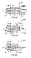
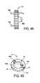
- FIGS. 4A, 4B, 4C and 4Dillustrate various views of a vertebra style control ring
- FIG. 5illustrates a segment and its associated control cables or tendons and a drive motor used to drive one of the tendons to control the movement of the segment;
- FIGS. 6, 7 and 8illustrate various embodiments of a segmented instrument having an embodiment of a vacuum brake assembly
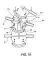
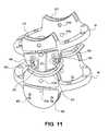
- FIGS. 9, 10, 11, and 12illustrate various views of an embodiment of a controllable instrument having braking capabilities
- FIGS. 13, 14, 15A, 15B and 16illustrate various views of another embodiment of a controllable instrument having braking capabilities
- FIG. 17illustrates an isometric view of another embodiment of a controllable instrument having braking capabilities
- FIG. 18illustrates an embodiment of an controllable instrument positioned within the esophagus and the stomach.
- FIG. 19illustrates an embodiment of a controllable instrument having a distal section with articulatable and lockable segments in different orientations.
- FIG. 1depicts a flexible endoscope 10 , in accordance with an embodiment of the present invention.
- Endoscope 10has elongate body 12 with steerable distal portion 14 , automatically controlled proximal portion 16 , and flexible and passively manipulated proximal portion 18 .
- automatically controlled proximal portion 16may also be flexible and passively manipulated, although it is preferred to provide automatically controlled proximal portion 16 .
- elongate body 12can have only steerable distal portion 14 and automatically controlled portion 16 .
- Fiber optic imaging bundle 20 and illumination fiber(s) 22may extend through elongate body 12 to steerable distal portion 14 , or video camera 24 (e.g., CCD or CMOS camera) may be positioned at the distal end of steerable distal portion 14 , as known by the skilled artisan.
- video camera 24e.g., CCD or CMOS camera
- a userviews live or delayed video feed from video camera 24 via a video cable (e.g., wire or optical fiber, not shown) or through wireless transmission of the video signal.
- endoscope 10will also include one or more access lumens, working channels, light channels, air and water channels, vacuum channels, and a host of other well known complements useful for both medical and industrial endoscopy.
- channels and other amenitiesare shown generically as 26 .
- these amenitiesmay include multiple tool channels in order to provide access for tools to a surgical site by passing the endoscope through a natural orifice proximate to a surgical target site, as in natural orifice transluminal (or transgastric) endoscopic surgery (NOTES).
- NOTESnatural orifice transluminal endoscopic surgery
- automatically controlled proximal portion 16comprises a plurality of segments 28 , which are controlled via computer and/or electronic controller 30 .
- Such an automatically controlled endoscopeis described in further detail in commonly assigned U.S. patent application Ser. No. 10/229,577 (now U.S. Pat. No. 6,858,005) and Ser. No. 11/750,988, both previously incorporated herein by reference.
- the distal end of a tendon(more thoroughly described below) is mechanically connected to a each segment 28 or steerable distal portion 14 , with the proximal end of the tendon mechanically connected to actuators to articulate segments 28 or steerable distal portion 14 , which is more fully described below and in U.S. patent application Ser. No.
- the actuators driving the tendonsmay include a variety of different types of mechanisms capable of applying a force to a tendon, e.g., electromechanical motors, pneumatic and hydraulic cylinders, pneumatic and hydraulic motors, solenoids, shape memory alloy wires, electronic rotary actuators or other devices or methods as known in the art. If shape memory alloy wires are used, they are preferably configured into several wire bundles attached at a proximal end of each of the tendons within the controller.
- Segment articulationmay be accomplished by applying energy, e.g., electrical current, electrical voltage, heat, etc., to each of the bundles to actuate a linear motion in the wire bundles which in turn actuate the tendon movement.
- energye.g., electrical current, electrical voltage, heat, etc.
- the linear translation of the actuators within the controllermay be configured to move over a relatively short distance to accomplish effective articulation depending upon the desired degree of segment movement and articulation.
- knobs attached to rack and pinion gearingcan be used to actuate the tendons attached to steerable distal portion 14 .
- An axial motion transducer 32(also called a depth referencing device or datum) may be provided for measuring the axial motion, i.e., the depth change, of elongate body 12 as it is advanced and withdrawn. As elongate body 12 of endoscope 10 slides through axial motion transducer 32 , it indicates the axial position of the elongate body 12 with respect to a fixed point of reference. Axial motion transducer 32 is more fully described in U.S. patent application Ser. Nos. 10/229,577 and 11/522,305, previously incorporated herein by reference. Additionally, an optical sensor may be used to determine the axial position of the endoscope, either alone or in combination with an optical shape sensor.
- NeoGuide Systemshas designed a fully segmented controllable instrument.
- An exemplary instrumentis described in U.S. Pat. No. 6,858,005 entitled Tendon Driven Endoscope. Additional details of a depth measurement system are described in U.S. patent application Ser. Nos. 10/988,212 and 10/384,252.
- handle 34is connected to illumination source 36 by illumination cable 38 that is connected to or continuous with illumination fibers 22 .
- Handle 34is connected to electronic controller 30 by way of controller cable 40 .
- Steering controller 42e.g., a joy stick
- Electronic controller 30controls the movement of the segmented automatically controlled proximal portion 16 .
- steerable distal portion 14 and segments 28 of automatically controlled proximal portion 16are preferably constructed from a plurality of links 46 .
- Five links 46are shown in this example for the sake of clarity, although the skilled artisan will recognize that any number of links may be used including just one link, the ultimate number being primarily defined by the purpose for which segments 28 or steerable distal portion 14 will be used.
- Each joint 47connects one link (e.g., 46 ) to an adjacent link (e.g., 46 ).
- Each link 46in this embodiment, can move with one degree of freedom relative to an adjacent link, and more than one link hinged together provides two degrees of freedom.
- FIG. 3A-Ca schematic diagram of either steerable distal portion 14 or segments 28 is provided for discussion purposes and to explain a preferred system and method for articulating steerable distal portion 14 or segments 28 .
- the skilled artisanwill recognize that the system and method for articulation is the same for both steerable distal portion 14 and segments 28 of automatically controlled proximal portion 16 . Therefore, the system and method for articulation will be described referring only to segments 28 , with the recognition that the description also applies equally to steerable distal portion 14 . It is noted that details relating to links 46 , joints 47 and the interconnections of the links have been eliminated from this figure for the sake of clarity.
- FIG. 3Ashows a three-dimensional view of segment 28 in its substantially straight configuration.
- the most distal link 46 A and most proximal link 46 Bare depicted as circles.
- Bowden cablesextend down the length of elongate body 12 (not shown in FIGS. 3A-C ) and comprise coil pipes 48 and tendons 50 .
- the proximal end of the Bowden-type cableis coupled to an actuator (not shown) and the distal end is coupled to the segment for which it controls articulation.
- Coil pipes 48house tendons 50 (i.e. a Bowden-type cable) along the length of elongate body 12 (not shown in FIGS. 3A-C ) and coil pipes 48 are fixed at the proximal end of segment 28 .
- Tendons 50extend out of coil pipes 48 at the proximal end of segment 28 along the length of segment 28 , and are mechanically attached to the distal portion of segment 28 . It will be appreciated that the distal end of tendons 50 need only be attached to the segment (or link if a segment is made up of only one link) being articulated by that tendon 50 at a location required to transfer the actuated force to that segment to effect articulation; the distal portion of the segment is provided by way of explanation and example, and not by way of limitation. In the variation depicted in FIG. 3A-C four tendons 50 are depicted to articulate segment 28 , but more or fewer may be used.
- the coil pipe/tendon combinationcan be used to apply force to articulate segments 28 and can be actuated remotely to deliver forces as desired to articulate segments 28 .
- actuation of one or more tendons 50causes segment 28 to articulate.
- links 46have joints 47 alternating by 90 degrees (see FIGS. 2 and 4 ).
- an assembly of multiple links 46is able to move in many directions, limited only by the number of actuated joints.
- tendons 50can be made from a variety of materials, which is primarily dictated by the purpose for which the endoscope will be used. Without limitation tendons 50 can be made from stainless steel, titanium, nitinol, ultra high molecular weight polyethylene, the latter of which is preferred, or any other suitable material known to the skilled artisan.
- tendons 50are used to articulate segment 28 , although more or fewer tendons could be used, as will be appreciated by the skilled artisan.
- Four tendonscan reliably articulate segment 28 in many directions.
- Tendons 50are attached at the most distal link 46 A, for the purposes of this discussion but not by way of limitation, close to the edge spaced equally apart at 12, 3, 6, and 9 O'clock. It will also be noted that an equal angle approximation has been made with this figure, that is the amount of bend is equally distributed to each of the joints of a segment.
- FIG. 3B-Cshow segment 28 articulated by independently pulling or slacking each of the four tendons 50 .
- pulling on tendon 50 at the 12 O'clock position and easing tension on tendon 50 at the 6 O'clock positioncauses steerable distal portion 28 to articulate in the positive y-direction with respect to the z-y-x reference frame 52 .
- the most distal z-y-x coordinate frame 52 distalrotates with respect to the z-y-x reference frame 52 and that ⁇ is the degree of overall articulation of segment 28 .
- links 46may be control rings to provide the structure needed to construct steerable distal portion 14 and segments 28 .
- Vertebrae-type control rings 54have two pairs of joints or hinges 58 A and 58 B; the first pair 58 A projecting perpendicularly from a first face of the vertebra and a second pair 58 B, located 90 degrees around the circumference from the first pair, projecting perpendicularly away from the face of the vertebra on a second face of the vertebra opposite to the first face.
- Hinges 58 A and 58 Bare tab-shaped, however other shapes may also be used.
- FIG. 4C-Dshows vertebra-type control ring 54 in sectional and perspective views.
- Control ring 54comprises body 66 , which is hingedly coupled to inner cross bar member 57 at joints 59 .
- Joints 59are the same joints at which a second link (although not shown) adjacent and proximal to link 54 is hingedly coupled to link 54 .
- Inner cross bar member 57is therefore hingedly coupled to two links at joints 59 , and can be thought of as being axially disposed “between” the two links.
- Cross bar member 57can also be fixed relative to one or both of the adjacent links.
- the exemplary inner cross bar member 57comprises force modifying elements 104 or purchase which each interact with a tendon 50 (not shown in FIGS. 4D and 4E ) to increase the amount of force applied to the articulatable segment when an actuation/tensioning force is applied to the tendon.
- Bar 105is provided as a tie-anchor for a tendon coming back down the segment from
- coil pipes 48 by-passing a vertebrae via quadrants 68will define an approximately cylindrical coil pipe containment space roughly defined by the outer diameter of vertebrae-type control ring 64 .
- Management of the coil pipesis more thoroughly discussed in co-assigned U.S. patent application Ser. No. 11/871,104 previously incorporated herein by reference.
- This spaceis loosely defined by the grouped coil pipes as they pass through and between the vertebrae.
- central aperture 56 or 56 ′ of the control ringscollectively forms a lumen (not shown) through which channels and cables necessary or desired for the endoscope function pass, as well as coil pipes and tendons by-passing that particular segment.
- coil pipes 48are fixed at their distal and proximal ends between actuators 60 and the proximal end of segment 28 under control by those actuators.
- FIG. 5shows only one segment 28 (which, as discussed, could also be steerable distal portion 14 ), and, for clarity, the other parts of a complete endoscope have been omitted from FIG. 5 .
- tendons 50When tendons 50 are placed under tension, the force is transferred across the length of segment 28 ; coil pipes 48 provide the opposite force at the proximal end of the segment being articulated in order to cause the articulation. This force is, primarily, axial loading transferred along the length of the coil pipe where it is fixed between the actuator and the proximal end of the segment being articulated.
- a preferred embodiment of the present inventionutilizes one actuator per tendon, and utilizes four tendons per segment, as described above, although only one actuator 60 is depicted for clarity. Details relating to actuator 60 and connecting actuator 60 to tendons 50 are described in U.S. patent application Ser. No. 10/988,212, previously incorporated by reference.
- coil pipes 48when elongate body 12 articulates (for example at the Sigmoid colon during a colonoscopy procedure or when retroflexing or navigating upon exiting the stomach in a NOTES procedure), coil pipes 48 must move longitudinally along elongate body 12 to either “gain” or “lose” length depending whether coil pipes 48 are on the inner or outer portion of the bend created by the articulation.
- an embodiment of the present inventionprovides quadrants 68 or coil pipe by-passing spaces 62 that permit the passage of coil pipes 48 along elongate body 12 until they reach the proximal portion of the segment they control.
- the “gain” or “loss” of coil pipe lengthrequires coil pipes 48 to slide up and down elongate body 12 and within quadrants 68 or coil pipe by-passing spaces 62 creating further frictional losses by virtue of friction between the coil pipes and/or between the coil pipes and the vertebra. There is also the additional friction created between a coil pipe and a tendon by virtue of the bend. Additionally, but related, elongate body 12 may enter more than one tortuous bend simultaneously. This may occur when going through a tortuous path such as the colon or when navigating the scope in open space (e.g., within the peritoneal cavity) to perform NOTES procedures. In one mode of operation, as described more thoroughly in U.S.
- electronic motion controller 30causes adjacent segments to adopt the shape of the segment or steerable distal portion immediately preceding it.
- coil pipes 48need to slide along elongate body 12 to accommodate the “gain” or “loss” of coil pipe length resulting from the articulation of elongate body 12 .
- this “gain” or “loss”the coil pipes are spiraled. In effect, it is believed, spiraling localizing the sliding of the coil pipes to the segment, thereby preventing binding of the coil pipes and catastrophic failure. This is described in further detail in co-pending, co-assigned U.S. patent application Ser. No. 11/871,104 titled System for Managing Bowden Cables in Articulating Instruments.
- Lockable tubes in the prior arthave the surface of one ring contacting the surface of an adjacent ring. Compression of the adjacent rings in these prior art lockable tubes increases the friction between the adjacent rings causing them to resist articulation relative to each other.
- embodiments of the inventions described hereinprovide additional frictional surfaces or in some embodiments multiplied frictional surfaces between articulating components. It is believed that the additional surfaces increase the frictional surface acting on the instrument. The additional frictional force in turn increases the braking or locking force applied to the instrument.
- Various embodiments of the present inventionprovide mechanisms by which the user can selectively rigidize all or a portion of the elongate body through the use of multiple surfaces placed between articulating segments or individual links or vertebra.
- the braking assemblies described hereinprovide multiplied friction and lock force, they remain capable of articulation when not engaged.
- the brake assemblyincludes the hinge or portion of a hinge or joint used for the articulation of the segmented instrument.
- a segmented instrumenthaving a plurality of links and at least one lockable and articulatable joint positioned to connect a pair of adjacent links in the plurality of links.
- the at least one lockable and articulatable jointbeing adapted and configured to increase the number of frictional surfaces available between the pair of adjacent links.
- cables and coil pipestake up a large amount of space along the elongate body.
- the brake assemblylies on or in the exterior surface of the segment, hinge or vertebra in order to keep the interior portions of the instrument free.
- the instrumentincludes an elongate body having a plurality of links.
- the instrumentmay be configured as any of a wide variety of surgical devices.
- the instrumentmay be an endoscope or other controllable instrument as described above or it may be a guide used to direct the movement or placement of another instrument including another segmented instrument.
- a hingeconnects a pair of adjacent links in the plurality of links.
- the skilled artisanwill readily recognize appropriate materials from which to make components in a brake assembly.
- the desired properties of the materials used in a brake assemblyinclude lubricity between layers when the brake is not actuated (e.g., braking force is not applied or no vacuum is pulled) and sufficient friction to bind the components or brake assembly when the brake is actuated (e.g., the braking force is applied or a vacuum is pulled).
- Another useful propertyis that the brake assembly has the flexibility to bend when a joint is articulated.
- Exemplary materials for use in brake assembly componentsinclude, without limitation, aluminum, carbon fiber, and various plastics such as and without limitation Teflon®.
- the brake assemblymay be on all or only some of the links, vertebra or segments of an instrument.
- the brake assembly or multiple brake assembliesmay be placed in isolated or only specific portions of the instrument. Numerous actuation mechanisms may be used to engage the brake assembly or assemblies.
- the brake assembliesare activated by pulling a cable running through or along the instrument.
- the interior of the scope(a normally sealed environment) is pumped down so that the interior is under vacuum. The action of the skin of the instrument being pulled in by the vacuum may be used to actuate a braking mechanism.
- the brake assembliesmay be activated serially or simultaneously or in any order depending upon circumstances in use.
- the brake assembly or assembliesmay be provided only in a distal portion of the links in the plurality of links.
- the brake assemblyis provided only in a proximal portion of the links in the plurality of links.
- the brake assemblyis provided only in a middle portion of the links in the plurality of links.
- the brake assemblyis provided only between a portion of the links in the plurality of links.
- the braking assemblywhere one or more are placed wherein the actuation of the brake assembly removes one degree of freedom from a portion of the instrument.
- a plurality of brake assembliesare coupled to the instrument.
- the actuation of the plurality of brake assembliessubstantially locks the shape of instrument by locking substantially all of the plurality of links in the instrument.
- the plurality of brake assembliesare coupled to the instrument wherein actuation of the plurality of brake assemblies substantially removes one degree of freedom from the movement of the segmented instrument.
- the brake assemblyis adapted and configured to complement the operation of the hinge so that the hinge remains articulatable when the brake assembly is not actuated or engaged.
- the brake assemblyis adapted and configured to increase the number of frictional surfaces between the pair of adjacent links.
- the recessed portion on the surface of the each of links in the pair of adjacent linkshas a generally rectangular shape or, alternatively, a generally arcurate shape.
- the brake assemblyis spaced apart from the at least one hinge. In one aspect, the brake assembly is spaced apart about 90 degrees about the circumference of the link from the at least one hinge. Practical limitations of the actual design of a specific instrument may alter the location of the braking mechanism. The spacing may be as close as practical to 90 degrees from the hinge location.
- the brake assemblymay also include a plurality of complementary shaped components.
- the complementary shaped componentsmay have surfaces adapted and configured to provide sliding motion when links move about the hinge.
- the complementary shaped componentsmay come in virtually any shape and orientation that allow sliding, relative movement.
- the plurality of complementary shaped componentsmay be provided by a plurality of interwoven slats. This is one example where the complementary surfaces are generally flat.
- the complementary surfacesare generally arcurate.
- a complementary shaped component positioned adjacent one link in the pair of linksmoves along with the movement of the other of the links in the pair of links.
- FIG. 6is an isometric view of an instrument with an embodiment of a brake assembly 700 .
- FIG. 7is an enlarged section view of a brake assembly 700 in FIG. 6 .
- FIG. 8illustrates a section view of two links and the forces applied to the brake assembly by the instrument skin 600 .
- the instrument elongate body 12has skin 600 over its outside.
- Skin 600is preferably made from some smooth, elastic and durable material in order to prevent trauma to the patient as elongate body 12 is moved about within the patient.
- FIG. 6is an isometric view of a portion of an instrument having six links 46 .
- This viewshows the instrument without skin 600 so that the position of the brake assembly 700 may be seen in relation to the hinge 47 .
- a brake assembly 700is attached between adjacent links 46 .
- the brake assembly 700is located approximately ninety degrees about the circumference of link 46 from joint 47 .
- the brake assemblies 700when engaged, substantially prevent articulation of link 46 about its joint 47 .
- the degree of freedom provided in each linkis substantially removed.
- a plurality of brake assembliesacts together, they substantially rigidize or lock the elongate body 12 in the shape existing when the brake assembly is actuated.
- FIG. 7illustrates a partial section view of an embodiment of a brake assembly 700 shown in FIG. 6 .
- brake assembly 700in one embodiment, includes interwoven slats or layers 800 .
- Interwoven slats or layers 800slide next to and between each other and are secured on either side of hinged links 46 by pins 802 .
- Slats or layers 800 Aare attached to link 46 A using pin 802 A.
- Slats or layers 800 Bare attached to link 46 B using pin 802 B.
- the location of pins 802 A, B and the length of the slats or layers 800 A, 800 Bare selected so that the overlapping region 800 C exists throughout the range of motion for the hinge 47 (not shown) associated with links 46 A, 46 B.
- the brake assembly 700can engage irrespective of the relative position of links 46 A, 46 B.
- This sliding arrangement of the slats/layers 800 A, 800 Bwhich permits articulation of joint 47 when brake assembly 700 is not engaged.
- a vacuumis pulled within elongate body 12 , and the pressure difference causes skin 600 to apply a force against links 46 and against brake assembly 700 , as depicted by arrows in FIG. 8 .
- This forceacts against the brake assembly 700 causing the interwoven slats or layers 800 A, 800 B to engage by pressing layers 800 A, 800 B together in the overlapping region 800 C as well as against each other and the surface of the links 46 A, 46 B.
- the increase of friction between layers 800 A, 800 B upon application of the forcecauses brake assembly 700 to engage, thereby inhibiting articulation of the joint across which the brake assembly spans. Release of the vacuum removes the force applied to brake assembly 700 by the skin 600 , thereby permitting sliding movement again between the slats 800 A, 800 B and articulation of the joints and the elongate body.
- the recessed portion 809is positioned on the surface of the each of links 47 in the pair of adjacent links.
- the recessed portion 809is sized and shaped to conform to the size and shape of a portion of a component in the brake assembly.
- the size and shape of the recessed portion 809corresponds to the size of the slats 800 A, 800 B and is generally rectangular like the slats 800 A, 800 B.
- the size and shape of the recess 809will vary with the specific brake assembly or technique being utilized.
- the recessed portion on the surface of the each of links in the pair of adjacent linksmay have a generally arcurate shape, a curved shape, an irregular shape or a compound shape.
- one or more cablesrunning along or through the edges of links 46 of elongate body 12 .
- Each joint of each vertebrae or link 46has brake assembly or articulating lockable brake assembly as described herein.
- the various alternative brake assemblieshave multiple surfaces that slide next to each other about a pivot point when force is not applied, thereby permitting articulation of the link.
- One aspect of the embodiments of the brake assemblies described herein that allows the surfaces to effectively multiply the friction at the jointis that the sliding plates between the rings can move freely separate along the central axis of the rings, but cannot rotate relative to either the upper or lower ring depending on which one they are contiguous with.
- the multiple surfaces of the brake assembliesbind when load is placed on the links, in this embodiment by applying tension to the cables.
- the applied tensioncompresses the links together, which in turn compresses multiple surfaces together preventing the links from articulating, and, thereby, rigidizing elongate body 12 .
- This designis not limited to just the number of interfaces depicted. For a given load, increasing the number of frictional interfaces increases the resistance to articulation.
- one or more brake assembly componentsmay be part of and contiguous with a link structure.
- one or more brake assembly componentsmay be slidingly pinned into a link structure such that it can have limited movement longitudinally up and down relative to a link structure. In this regard, it may in essence be part of a link structure as well.
- Other brake assembly componentsmay be attached to a link structure 46 by pivot arms and such that these surfaces may articulate along upper arched surfaces or other complementary surfaces of 958 of a link structure 46 .
- each link structure 46contributes two surfaces to either side of a brake assembly, for a total of three contact surfaces for each joint.
- link structure 46for the passage of cables 900 used to articulate the links and other cables to compress the multiple surfaces together, thereby locking link structures relative to each other.
- the surfaces described above and in the various brake assembly embodimentswill slide relative to each other to permit bending or articulation of the controllable instrument (e.g. guide tube or segmented controllable instrument) made from the ring structures and brake assemblies.
- the controllable instrumente.g. guide tube or segmented controllable instrument
- the components of the brake assembly 900are compressed via a cable that runs through links 46 , as previously described. Tension in the cables is generated using a lead screw with a balance bar to distribute the load evenly between joints. Any method that generates a compressive load is acceptable given that the loads do not act to articulate the joint, but rather to compress it. The compressive load should act directly through the pivot point of the joint if possible.
- articulation of each linkhas one degree of freedom, as described above.
- the direction of the degree of freedomalternates for adjacent links and is orthogonal for adjacent links.
- segments made of multiple linkscan be articulated in multiple directions using tendons and actuators, as described above.
- the articulating elongate bodycan be selectively rigidized by actuating the cables.
- the multiplying surfacescan be used to selectively rigidize an over tube, which is used to guide an instrument.
- the instrumentcan either be a passive endoscope, such as that made by Olympus, or a fully controlled articulating scope, such as that described above and in development by NeoGuide Systems, Inc.
- FIGS. 9-12illustrate various views of another embodiment of a segmented instrument having braking capabilities.
- FIG. 9there is an illustration of an elongate body having a plurality of links 46 .
- the brake assembly 900is also positioned to span the distance between the pair of adjacent links 46 .
- a cable 92extends through the plurality of brake assemblies 900 to a stopper 93 on the distal end.
- the stopper 93engages with the components of the brake assembly 900 to engage and lock the position of the segmented instrument.
- FIGS. 10, 11 and 12The internal components of the brake assembly 900 are best seen in the views provided by FIGS. 10, 11 and 12 .
- FIGS. 10 and 11provide side and isometric views, respectively, of at least two links coupled together by the brake assembly 900 .
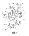
- the specific components of the brake assemblywill now be described with reference to the exploded view of FIG. 12 .
- FIG. 12illustrates an exploded view of the components of an exemplary brake assembly 900 .
- the link 46includes a brake assembly base 905 having shaped upper complementary surface 910 and lower shaped complementary surface 915 .
- Apertures 918 U, 918 Lare formed in the base are sized and positioned to receive the common pins 925 provided by arms 920 .
- Apertures 955are sized and positioned to receive pins 950 of the link slider 940 .
- Arm 920includes common pins 925 T on one end and pins 925 B on the other.
- the pins 925 Tcouple to apertures 918 L and the pins 925 B couple to the apertures 918 U.
- the common pins and the armsprovide the hinge between the links and allow for relative movement between adjacent links.
- the arms 920 shown in the view of FIG. 12illustrate the connection between pins 918 U into aperture 918 U of the link 46 shown in the figure.
- the arm 920also passes through the arm slider 930 and link slider 940 .
- Arm slider 930includes an aperture 935 for the arm 920 .
- Link slider 940includes an aperture 945 for the arm 935 .
- the arm slider 930is shaped to provide complementary surfaces for both the base upper surface 910 to one side and the base lower surface 915 to the other. As shown in the views of FIGS. 10 and 11 , when the brake assembly 900 is in use, the arm slider 930 is in sliding relation and has complementary shape to slide between the link upper and lower surfaces 910 , 915 .
- the arm slidermoves independent of the links 46 and provides additional friction surfaces to lock the relative position of the links 46 .
- the link slider 940also provides additional friction lock surfaces.
- the link slider 940is pinned to the link using the pins 950 and apertures 955 . As such the link slider moves with the link 46 .
- the link slider 940has complementary shaped surfaces that provide the increased number of friction surfaces between the base lower surface 915 and the arm slider 930 and the base upper surface 910 .
- both the arm slider 930 and the link slider 940have apertures adapted and configured to fit around and permit passage of the arm 920 .
- the complementary surfaces and increased friction lock surfacesare, from the base lower surface 915 of the upper link 46 : lower base surface 915 contacts the upper surface of the arm slider 930 , the lower surface of the arm slider 930 contacts the upper surface of the link slider 940 and the lower surface of the link slider 940 contacts the upper base surface 910 of the lower link 46 .
- Each of the above surfaceshas a complementary shape that allows sliding movement and articulation of the links 46 when the brake 900 is not engaged. When engaged, the surfaces and components above act in concert to lock the relative position of the links 46 .
- FIGS. 13-16illustrate another alternative embodiment of a segmented instrument having braking capabilities.
- the brake assembly 1400is shown in use on an elongate body having a plurality of links 46 . There is a hinge provided within the brake this embodiment of the brake assembly 1400 that connects a pair of adjacent links 46 as shown in FIGS. 13, 14 and 15B .
- the brake assembly 1400is coupled to each link 46 in the pair of adjacent links and positioned to span the distance between the pair of adjacent links. Similar to the brake assembly 900 , the brake assembly 1400 also includes components that have complementary shapes, provide for relative movement when the brake is not engage and multiply the number of friction surfaces when the brake 1400 is engaged.
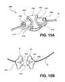
- the individual components of the brake assembly 1400are best seen in the views of FIGS. 15A and 16 .
- the brake assembly 1400includes a carrier plate 1410 , a central sliding block 1405 and arms 1425 having arm sliders 1430 .
- a lock plate 1440(shown in FIGS. 14 and 14 ) is used to secure components to the carrier plate 1410 .
- the arms 1425include apertures 1435 for the common pivot pin 1420 , best seen in FIG. 15A .
- pulling the cable 92will decrease the spacing between central block 1405 , arm sliders 1430 and base sliders 1415 and bring the complementary surfaces of these components into locking contact. Similar to the brake assembly 900 , the added friction surfaces will act to enhance the locking capabilities provided by the brake assembly 1400 . Both sides of the arm slider are engaged as it is compressed between the central sliding block 1405 and the base slider 1415 .
- FIGS. 14 and 15provide additional views of a plurality of links 46 joined together by a number of brake assemblies 1400 .
- FIG. 14illustrates the cables 92 A, 92 B that may be used independently or in concert to actuate the brake assemblies 1400 .
- FIG. 13illustrates a central lumen 1470 in relation to the links 46 .
- the central lumen 1470could be another instrument, as would be the case when the plurality of links 46 shown is configured to act as a guide tube.
- the central lumen 1470could be the interior components of a instrument (working channels, provisions for light, air, water and video capabilities commonly provided in endoscopy for example) when the plurality of links are configured as part of a controllable segmented instrument.
- control cables and other components described above and else where in this applicationwould also be provided in order to provide steering control of the instrument formed by the links 46 .
- FIG. 17illustrates still another alternative embodiment of a brake assembly according to the present invention.
- FIG. 17is an isometric view of a segmented instrument having braking capabilities provided by the brake assembly 1800 .
- the brake assembly 1800is coupled to each link in the pair of adjacent links and positioned to span the distance between the pair of adjacent links.
- a brake assembly 1800spans the distance between the link 46 A and 46 B and another brake assembly spans the distance between the links 46 B and 46 C.
- the brake assembly 1800provides articulation and locking capabilities between adjacent links. Moreover, the configuration and interoperability of the components of the brake assembly 1800 like the previous embodiments also provides an increased number of friction locking surfaces to enhance and magnify the applied locking force.
- the brake assembly 1800includes a central sliding block 1805 .
- a base slider plate 1810is attached to the central sliding block 1805 .
- a center plate 1815is also attached to the central sliding block 1805 and is positioned between the base slider plate 1810 and the hinge plate 1820 attached to the link 46 B.
- the complementary surfaces of the central sliding block 1805 , base slider 1810 , center plate 1815 and the hinge plate 1820allow for relative and sliding movement between these components, and the adjacent links 46 when the brake assembly 1800 is not engaged.
- the center plateis engaged between the base slider 1810 and the hinge plate 1820 .
- the hinge plate 1820is engaged to the complimentary surface 1825 of the link.
- the base slideris engaged against the complementary surface of the central sliding block 1805 .
- the various braking assemblies described hereinmay be adapted and configured to operate in a number of different contexts.
- the links and the brake assembliesmay be configured to operate as an endoscope or other segmented controllable instrument.
- the links and braking assembliesmay be configured to function as a guide tube so that another instrument may pass through the central lumen of the links 46 .
- the links and brake assembliesare configured into hybrid instruments having both highly controllable sections and the flexible and lockable sections.
- the proximal portion of that controllable instrumentmay be configured to be flexible and include locking assemblies.
- the hybrid instrumenthas articulation and control need in the surgical site while providing a proximal end that may be used as a base or support for the distal end.
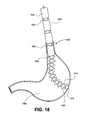
- FIG. 18is one exemplary embodiment of an instrument 1800 having a distal end 1810 and a proximal end 1805 .
- the distal endincludes hinges 1815 and flexible segments 1820 .
- the proximal end 1805includes flexible segments 1830 and articulating brake assemblies 1825 .
- the proximal end segments 1830are larger than the segments 1820 because the distal end in this embodiment is configured for greater articulation and control capabilities.
- the change in the size of the segments and control of the instrument or function of the instrumentchanges at the flexible-base transition 1840 . As shown in the illustrative embodiment of FIG.
- the instrument 1800is positioned in the alimentary canal with the distal end positioned just prior to forming an opening in the stomach 1890 in furtherance of a transgastric or transluminal or other NOTES procedure.
- the distal end of highly articulating endcould be advanced through the opening up to or beyond the transition point 1840 .
- the proximal endmay be advanced through the transluminal opening, there are configurations where the relative lengths of the proximal and distal ends are selected so that when the distal section is in the surgical site the proximal end in positioned and locked within the esophagus 1885 and stomach 1890 to provide a base for the operation of the articulating distal end 1810 .
- the hinges 1815may also be configured as brake assemblies as described herein so that the distal end may articulate, including computer controlled articulation as described herein, and also have the enhanced locking capabilities of the brake assemblies of the present invention.
- FIG. 19is another exemplary embodiment of an instrument 1900 having a distal end 1905 and a proximal end 1823 .
- the distal end 1905includes hinges 1913 and flexible segments.
- the distal end 1905is divided into a distal section 1910 where the hinges 1913 are aligned to provide articulation in a first orientation and a proximal section 1920 where the hinges 1913 are aligned to provide articulation in a second orientation.
- the transition section 1915is adapted and configured to provide the transition between the different orientations of the articulation in the distal section 1910 and the proximal section 1920 .
- the instrument 1900also includes a proximal end 1923 that includes flexible segments 1830 and articulating brake assemblies 1825 .
- the proximal end segments 1830are larger than the segments 1820 because the distal end in this embodiment is configured for greater articulation and control capabilities.
- the change in the size of the segments and control of the instrument or function of the instrumentchanges at the flexible-base transition 1840 .
- the embodiment of instrument 1900may be placed in the alimentary canal with the distal end positioned just prior to forming an opening in the stomach in furtherance of a transgastric or transluminal or other NOTES procedure. Once the opening is formed and the distal end is advanced, the distal end 1905 may be advanced through the opening up to or beyond the transition point 1840 .
- proximal end 1923may be advanced through the transluminal opening, there are configurations where the relative lengths of the proximal and distal ends are selected so that when the distal section is in the surgical site the proximal end in positioned and locked within the esophagus 1885 and stomach 1890 to provide a base for the operation of the articulating distal end 1905 .
- the hinges 1913 , 1825may also be configured as brake assemblies as described herein so that the distal end may articulate, including computer controlled articulation as described herein, and also have the enhanced locking capabilities of the brake assemblies of the present invention. It is to be appreciated that the orientations between the distal sections 1910 , 1920 may be changed or specifically adapted for a particular procedure or NOTES access site.
- Embodiments of the present inventionmay be modified and adapted as needed to facilitate entry and access to surgical site via natural orifice (such as, for example, through the mouth, the anus/colon or the vagina or other openings formed once the instrument has accessed the alimentary canal), surgically created openings including laparoscopic or single port access openings or other percutaneous openings.
- other embodiments of the instruments having braking capabilities as described hereinmay be configured as rigidizable external working channels as well as rigidizable external working channels that can be separated from another scope or instrument.
- the segmented instrument with braking capabilitiesmay also be used to aid a physician in the performance of a surgical procedure.
- This aspectincludes a method of controlling a segmented instrument. First, there is a step of introducing a segmented instrument into a patient, the segmented instrument having a plurality of links wherein adjacent links are joined by a hinge. Next, there is a step of manipulating the links about the hinges to maneuver the segmented instrument to provide access to a surgical site within the patient. In one aspect, the manipulating step produces a sliding motion between a plurality of complementary shaped components within a portion of a brake assembly between adjacent links. Next, there is also a step of actuating the brake assembly to substantially prevent movement about the hinge of the links attached to the braking mechanism.
- the actuating step in the method of controlling a segmented instrumentmay take any of several forms.
- the actuating stepmay include applying vacuum to the interior of the segmented instrument.
- the actuating stepcomprises pulling a cable. It is to be appreciated that the actuating step substantially locks the shape of a portion of the controllable instrument.
- the method of controlling a segmented instrumentmay also include advancing a surgical implement through a working channel in the segmented instrument to the surgical site. Additionally or alternatively, the advancing step is performed after the actuating step. In still other alternative methods, there is also a step of accessing the surgical site with a controllable surgical instrument advanced through the segmented instrument. In addition, the advancing step is performed before, after or during the actuating step.
- inventive brake assemblies described hereinmay be applied to the guide tubes and controllable segmented instruments and used in the various methods described in the co-pending and commonly assigned application “METHODS AND APPARATUS FOR PERFORMING TRANSLUMINAL AND OTHER PROCEDURES” filed on Sep. 14, 2006 as application Ser. No. 11/522,305, now published patent application number US 2007-0135803 (published on Jun. 14, 2007).
- the brake assemblies and other details described hereinmay also be configured and controlled as those instruments in and used to perform the surgical procedures described in the commonly assigned and co-pending “APPARATUS AND METHODS FOR AUTOMATICALLY CONTROLLING AN ENDOSCOPE” filed on Jan. 29, 2009 as PCT/US2009/032481.
Landscapes
- Health & Medical Sciences (AREA)
- Life Sciences & Earth Sciences (AREA)
- Surgery (AREA)
- Physics & Mathematics (AREA)
- General Health & Medical Sciences (AREA)
- Molecular Biology (AREA)
- Veterinary Medicine (AREA)
- Public Health (AREA)
- Nuclear Medicine, Radiotherapy & Molecular Imaging (AREA)
- Engineering & Computer Science (AREA)
- Biomedical Technology (AREA)
- Heart & Thoracic Surgery (AREA)
- Medical Informatics (AREA)
- Animal Behavior & Ethology (AREA)
- Optics & Photonics (AREA)
- Pathology (AREA)
- Biophysics (AREA)
- Radiology & Medical Imaging (AREA)
- Rehabilitation Therapy (AREA)
- Surgical Instruments (AREA)
- Astronomy & Astrophysics (AREA)
- General Physics & Mathematics (AREA)
- Oral & Maxillofacial Surgery (AREA)
Abstract
Description
Claims (23)
Priority Applications (1)
| Application Number | Priority Date | Filing Date | Title |
|---|---|---|---|
| US12/866,309US10512392B2 (en) | 2008-02-06 | 2009-02-06 | Segmented instrument having braking capabilities |
Applications Claiming Priority (3)
| Application Number | Priority Date | Filing Date | Title |
|---|---|---|---|
| US2662808P | 2008-02-06 | 2008-02-06 | |
| US12/866,309US10512392B2 (en) | 2008-02-06 | 2009-02-06 | Segmented instrument having braking capabilities |
| PCT/US2009/033446WO2009100368A1 (en) | 2008-02-06 | 2009-02-06 | A segmented instrument having braking capabilities |
Related Parent Applications (1)
| Application Number | Title | Priority Date | Filing Date |
|---|---|---|---|
| PCT/US2009/033446A-371-Of-InternationalWO2009100368A1 (en) | 2008-02-06 | 2009-02-06 | A segmented instrument having braking capabilities |
Related Child Applications (1)
| Application Number | Title | Priority Date | Filing Date |
|---|---|---|---|
| US16/697,805DivisionUS10952594B2 (en) | 2008-02-06 | 2019-11-27 | Segmented instrument having braking capabilities |
Publications (2)
| Publication Number | Publication Date |
|---|---|
| US20110295065A1 US20110295065A1 (en) | 2011-12-01 |
| US10512392B2true US10512392B2 (en) | 2019-12-24 |
Family
ID=40952471
Family Applications (2)
| Application Number | Title | Priority Date | Filing Date |
|---|---|---|---|
| US12/866,309Active2031-06-23US10512392B2 (en) | 2008-02-06 | 2009-02-06 | Segmented instrument having braking capabilities |
| US16/697,805ActiveUS10952594B2 (en) | 2008-02-06 | 2019-11-27 | Segmented instrument having braking capabilities |
Family Applications After (1)
| Application Number | Title | Priority Date | Filing Date |
|---|---|---|---|
| US16/697,805ActiveUS10952594B2 (en) | 2008-02-06 | 2019-11-27 | Segmented instrument having braking capabilities |
Country Status (4)
| Country | Link |
|---|---|
| US (2) | US10512392B2 (en) |
| EP (1) | EP2249690B1 (en) |
| KR (2) | KR101583246B1 (en) |
| WO (1) | WO2009100368A1 (en) |
Cited By (4)
| Publication number | Priority date | Publication date | Assignee | Title |
|---|---|---|---|---|
| US20190053688A1 (en)* | 2016-05-18 | 2019-02-21 | Olympus Corporation | Endoscope bending tube manufacturing method |
| US20220016394A1 (en)* | 2020-07-16 | 2022-01-20 | Canon U.S.A., Inc. | Medical Apparatus and Method of Use Thereof |
| US20230338100A1 (en)* | 2014-09-09 | 2023-10-26 | Intuitive Surgical Operations, Inc. | Flexible medical instrument |
| US20250059958A1 (en)* | 2021-12-22 | 2025-02-20 | Cambridge Mechatronics Limited | Actuator assembly |
Families Citing this family (34)
| Publication number | Priority date | Publication date | Assignee | Title |
|---|---|---|---|---|
| KR101583246B1 (en) | 2008-02-06 | 2016-01-12 | 인튜어티브 서지컬 오퍼레이션즈 인코포레이티드 | A segmented instrument having braking capabilities |
| US8968355B2 (en)* | 2008-08-04 | 2015-03-03 | Covidien Lp | Articulating surgical device |
| GB201003516D0 (en)* | 2010-03-03 | 2010-04-21 | Surgical Innovations Ltd | Instruments |
| US20110251599A1 (en)* | 2010-04-13 | 2011-10-13 | Carson Shellenberger | Deflectable instrument shafts |
| US9387043B2 (en) | 2011-05-12 | 2016-07-12 | Imperial Innovations Limited | Medical master/slave type device for minimally invasive surgery |
| US8603135B2 (en)* | 2011-07-20 | 2013-12-10 | Covidien Lp | Articulating surgical apparatus |
| US9119639B2 (en)* | 2011-08-09 | 2015-09-01 | DePuy Synthes Products, Inc. | Articulated cavity creator |
| EP3372143B1 (en)* | 2011-10-21 | 2020-09-02 | Viking Systems, Inc. | Steerable electronic stereoscopic endoscope |
| US9226741B2 (en)* | 2012-01-09 | 2016-01-05 | Covidien Lp | Triangulation methods with hollow segments |
| KR101405087B1 (en)* | 2012-04-27 | 2014-06-10 | 한양대학교 에리카산학협력단 | An articulation for surgical instrument |
| KR101486645B1 (en)* | 2012-05-07 | 2015-01-29 | 정창욱 | Instrument for Minimally Invasive Surgery Having Variable Bending |
| US9439693B2 (en) | 2013-02-01 | 2016-09-13 | DePuy Synthes Products, Inc. | Steerable needle assembly for use in vertebral body augmentation |
| KR20140121933A (en) | 2013-04-08 | 2014-10-17 | 삼성전자주식회사 | Surgical robot |
| KR20140134491A (en) | 2013-05-14 | 2014-11-24 | 삼성전자주식회사 | Robot control method |
| WO2015066536A1 (en)* | 2013-10-31 | 2015-05-07 | Graham Howard P | Flexible structures |
| JP6234332B2 (en)* | 2014-06-25 | 2017-11-22 | オリンパス株式会社 | Endoscope apparatus, operation method, and operation program |
| US10675755B2 (en) | 2015-04-27 | 2020-06-09 | Fondazione Istituto Italiano Di Tecnologia | Shape-keeping deployable structure including a pair of robotic systems of the continuum type |
| EP3207853A4 (en)* | 2015-06-08 | 2018-06-13 | Olympus Corporation | Endoscope |
| CN109789292B (en)* | 2016-10-05 | 2022-11-01 | 祥丰医疗私人有限公司 | Modular vascular catheter |
| EP3568114A1 (en) | 2016-11-04 | 2019-11-20 | Ably Medical AS | Hospital bed |
| US10398486B2 (en) | 2017-06-20 | 2019-09-03 | Judd Michael Smith | Articulating wire passer |
| EP3539450B1 (en) | 2018-03-14 | 2024-01-24 | Ambu A/S | A tip part for a vision device |
| IL259807B (en) | 2018-06-04 | 2020-02-27 | Valuebiotech Israel Ltd | Articulation arm link |
| EP3610776A1 (en) | 2018-08-14 | 2020-02-19 | ETH Zurich | Articulated segmented instrument |
| EP3669744B1 (en) | 2018-12-21 | 2025-07-09 | Ambu A/S | An articulated tip part for an endoscope |
| US12349869B2 (en)* | 2018-12-21 | 2025-07-08 | Ambu A/S | Articulated tip part for an endoscope |
| KR20210145189A (en)* | 2019-04-01 | 2021-12-01 | 포티메딕스 에셋츠 Ii 비.브이. | A steerable instrument comprising a hinge having a slotted structure |
| NL2022849B1 (en)* | 2019-04-01 | 2020-10-08 | Fortimedix Assets Ii B V | Steerable instrument comprising a hinge with a slotted structure |
| DE102019121037A1 (en)* | 2019-08-05 | 2021-02-11 | Karl Storz Se & Co. Kg | Endoscopic device |
| CN120093197A (en)* | 2019-12-19 | 2025-06-06 | 诺亚医疗集团公司 | Modular endoscopy systems and methods |
| WO2021152756A1 (en)* | 2020-01-30 | 2021-08-05 | 三菱重工業株式会社 | Non-destructive inspection device and non-destructive inspection method |
| EP3925512A1 (en) | 2020-06-19 | 2021-12-22 | Ambu A/S | An endoscope comprising an articulated bending section body |
| US20220039784A1 (en)* | 2020-08-06 | 2022-02-10 | Canon U.S.A., Inc. | Remotely powered articulated medical apparatus |
| CN113425227B (en)* | 2021-06-24 | 2022-09-06 | 哈尔滨工业大学 | Diagnosis-treatment integrated soft enterogastroscope medical robot |
Citations (354)
| Publication number | Priority date | Publication date | Assignee | Title |
|---|---|---|---|---|
| US616672A (en) | 1898-12-27 | kelling | ||
| US2241576A (en) | 1940-03-20 | 1941-05-13 | Charles L Barton | Figure toy |
| US2510198A (en) | 1947-10-17 | 1950-06-06 | Earl B Tesmer | Flexible positioner |
| US2533494A (en) | 1949-02-18 | 1950-12-12 | Jr Iverson O Mitchell | Adjustable article support |
| US2767705A (en) | 1954-10-08 | 1956-10-23 | Technical Oil Tool Corp | Sigmoidoscope with suction attachment for immobilizing adjacent tissue |
| US3060972A (en) | 1957-08-22 | 1962-10-30 | Bausch & Lomb | Flexible tube structures |
| US3071161A (en) | 1960-05-16 | 1963-01-01 | Bausch & Lomb | Bidirectionally flexible segmented tube |
| US3096962A (en) | 1960-02-04 | 1963-07-09 | Meijs Pieter Johannes | Locking device for a measuring apparatus or the like |
| US3162214A (en) | 1963-01-16 | 1964-12-22 | American Optical Corp | Flexible tubular structures |
| US3168274A (en) | 1962-09-18 | 1965-02-02 | Polymathic Engineering Company | Supporting stand for instruments, tools and the like |
| US3190286A (en) | 1961-10-31 | 1965-06-22 | Bausch & Lomb | Flexible viewing probe for endoscopic use |
| US3266059A (en)* | 1963-06-19 | 1966-08-16 | North American Aviation Inc | Prestressed flexible joint for mechanical arms and the like |
| US3430662A (en) | 1964-09-21 | 1969-03-04 | Stephen Guarnaschelli | Flexible segmented tube |
| US3497083A (en) | 1968-05-10 | 1970-02-24 | Us Navy | Tensor arm manipulator |
| US3546961A (en) | 1967-12-22 | 1970-12-15 | Gen Electric | Variable flexibility tether |
| US3610231A (en) | 1967-07-21 | 1971-10-05 | Olympus Optical Co | Endoscope |
| US3625084A (en) | 1970-09-21 | 1971-12-07 | Nasa | Flexible/rigidifiable cable assembly |
| US3643653A (en) | 1968-12-24 | 1972-02-22 | Olympus Optical Co | Endoscopic apparatus |
| US3739770A (en) | 1970-10-09 | 1973-06-19 | Olympus Optical Co | Bendable tube of an endoscope |
| US3773034A (en) | 1971-11-24 | 1973-11-20 | Itt Research Institute | Steerable catheter |
| US3858578A (en) | 1974-01-21 | 1975-01-07 | Pravel Wilson & Matthews | Surgical retaining device |
| US3897775A (en) | 1973-09-07 | 1975-08-05 | Olympus Optical Co | Endoscope with facile bending operation |
| US3913565A (en) | 1973-05-18 | 1975-10-21 | Olympus Optical Co | Guide tube for a treating instrument to be inserted into body cavity |
| US3946727A (en) | 1971-06-15 | 1976-03-30 | Olympus Optical Co., Ltd. | Flexible tube assembly for an endoscope |
| US4054128A (en) | 1976-09-28 | 1977-10-18 | Universite De Sherbrooke | Device for carrying observation and/or manipulation instruments |
| US4176662A (en) | 1977-06-17 | 1979-12-04 | The United States Of America As Represented By The Administrator Of The National Aeronautics And Space Administration | Apparatus for endoscopic examination |
| US4236509A (en) | 1976-12-28 | 1980-12-02 | Nagashige Takahashi | Curving device in an endoscope |
| US4240435A (en) | 1978-10-03 | 1980-12-23 | Fumi Yazawa | Hair tweezers |
| US4272873A (en) | 1978-04-27 | 1981-06-16 | J. M. Voith Gmbh | Stone roller |
| US4273111A (en) | 1978-12-22 | 1981-06-16 | Olympus Optical Co., Ltd. | Endoscope with bend angle control |
| US4286585A (en) | 1978-12-22 | 1981-09-01 | Olympus Optical Co., Ltd. | Bend angle control for endoscope |
| SU871786A1 (en) | 1978-12-04 | 1981-10-15 | Сктб Средств Неразрушающего Контроля | Pipe for endoscopy |
| US4327711A (en) | 1979-11-16 | 1982-05-04 | Olympus Optical Co., Ltd. | Flexible tube for an endoscope |
| US4366810A (en) | 1980-08-28 | 1983-01-04 | Slanetz Jr Charles A | Tactile control device for a remote sensing device |
| US4393728A (en) | 1979-03-16 | 1983-07-19 | Robotgruppen Hb | Flexible arm, particularly a robot arm |
| US4432349A (en) | 1979-04-03 | 1984-02-21 | Fuji Photo Optical Co., Ltd. | Articulated tube structure for use in an endoscope |
| US4489826A (en) | 1982-02-05 | 1984-12-25 | Philip Dubson | Adjustable apparatus |
| US4494417A (en) | 1979-03-16 | 1985-01-22 | Robotgruppen Hb | Flexible arm, particularly a robot arm |
| US4499895A (en) | 1981-10-15 | 1985-02-19 | Olympus Optical Co., Ltd. | Endoscope system with an electric bending mechanism |
| US4503842A (en) | 1981-11-04 | 1985-03-12 | Olympus Optical Co., Ltd. | Endoscope apparatus with electric deflection mechanism |
| US4543090A (en) | 1983-10-31 | 1985-09-24 | Mccoy William C | Steerable and aimable catheter |
| US4551061A (en) | 1983-04-18 | 1985-11-05 | Olenick Ralph W | Flexible, extensible robot arm |
| US4559928A (en) | 1981-10-22 | 1985-12-24 | Olympus Optical Co., Ltd. | Endoscope apparatus with motor-driven bending mechanism |
| US4566843A (en) | 1982-09-22 | 1986-01-28 | Hitachi, Ltd. | Multiarticulated manipulator |
| DE2823025C2 (en) | 1978-05-26 | 1986-02-06 | Rolf 2300 Quarnbek Emeis | Device for transporting an instrument (colonoscope) for colon diagnostics and / or therapy |
| US4577621A (en) | 1984-12-03 | 1986-03-25 | Patel Jayendrakumar I | Endoscope having novel proximate and distal portions |
| US4592341A (en) | 1984-05-23 | 1986-06-03 | Olympus Optical Co., Ltd. | Method and apparatus for guiding prosthesis |
| US4601705A (en) | 1983-10-31 | 1986-07-22 | Mccoy William C | Steerable and aimable catheter |
| US4601283A (en) | 1981-12-07 | 1986-07-22 | Machida Endoscope Co., Ltd. | Endoscope with a memory shape alloy to control tube bending |
| SU1256955A1 (en) | 1985-01-17 | 1986-09-15 | Всесоюзный Проектно-Технологический Институт Тяжелого Машиностроения | Manipulator |
| US4621618A (en) | 1984-02-28 | 1986-11-11 | Olympus Optical Company, Ltd. | Dual viewing and control apparatus for endoscope |
| US4624243A (en) | 1985-04-08 | 1986-11-25 | American Hospital Supply Corp. | Endoscope having a reusable eyepiece and a disposable distal section |
| US4630649A (en) | 1984-05-02 | 1986-12-23 | Kabushiki Kaisha Machida Seisakusho | Guide tube for industrial endoscope |
| US4643184A (en) | 1982-09-29 | 1987-02-17 | Mobin Uddin Kazi | Embolus trap |
| US4646722A (en) | 1984-12-10 | 1987-03-03 | Opielab, Inc. | Protective endoscope sheath and method of installing same |
| US4648733A (en) | 1984-07-14 | 1987-03-10 | Robert Merkt | Device for producing an installation template for conduits, especially conduits for hydraulic or pneumatic control or process circuits |
| US4651718A (en) | 1984-06-29 | 1987-03-24 | Warner-Lambert Technologies Inc. | Vertebra for articulatable shaft |
| SU1301701A1 (en) | 1985-11-04 | 1987-04-07 | Государственный Научно-Исследовательский Институт Машиноведения Им.А.А.Благонравова | Industrial robot actuating device |
| US4655257A (en) | 1985-03-25 | 1987-04-07 | Kabushiki Kaisha Machida Seisakusho | Guide tube assembly for industrial endoscope |
| US4683773A (en) | 1985-06-27 | 1987-08-04 | Gary Diamond | Robotic device |
| US4686963A (en) | 1986-03-05 | 1987-08-18 | Circon Corporation | Torsion resistant vertebrated probe of simple construction |
| US4712969A (en) | 1983-08-29 | 1987-12-15 | Kabushiki Kaisha Toshiba | Expandable and contractable arms |
| JPS63136014A (en) | 1986-11-28 | 1988-06-08 | Res Dev Corp Of Japan | Active bending device for flexible tube |
| US4753223A (en) | 1986-11-07 | 1988-06-28 | Bremer Paul W | System for controlling shape and direction of a catheter, cannula, electrode, endoscope or similar article |
| US4753222A (en) | 1985-12-13 | 1988-06-28 | Olympus Optical Co., Ltd. | Endoscopic flexible tube |
| DE3707787A1 (en) | 1987-03-11 | 1988-09-22 | Patrik Dr Med Gruendler | Endoscope |
| JPS63272322A (en) | 1987-05-01 | 1988-11-09 | Olympus Optical Co Ltd | Apparatus for detecting curvature of leading end part of endoscope |
| US4787369A (en) | 1987-08-14 | 1988-11-29 | Welch Allyn, Inc. | Force relieving, force limiting self-adjusting steering for borescope or endoscope |
| US4788967A (en) | 1985-11-13 | 1988-12-06 | Olympus Optical Co., Ltd. | Endoscope |
| US4790624A (en) | 1986-10-31 | 1988-12-13 | Identechs Corporation | Method and apparatus for spatially orienting movable members using shape memory effect alloy actuator |
| US4793326A (en) | 1986-12-08 | 1988-12-27 | Olympus Optical Co., Ltd. | Endoscope having insertion end guide means |
| US4796607A (en) | 1987-07-28 | 1989-01-10 | Welch Allyn, Inc. | Endoscope steering section |
| US4799474A (en) | 1986-03-13 | 1989-01-24 | Olympus Optical Co., Ltd. | Medical tube to be inserted in body cavity |
| US4815450A (en) | 1988-02-01 | 1989-03-28 | Patel Jayendra I | Endoscope having variable flexibility |
| US4832473A (en) | 1987-02-06 | 1989-05-23 | Olympus Optical Co., Ltd. | Endoscope with elastic actuator comprising a synthetic rubber tube with only radial expansion controlled by a mesh-like tube |
| US4834068A (en) | 1988-03-18 | 1989-05-30 | Gottesman James E | Barrier shield method and apparatus for optical-medical devices |
| US4846573A (en) | 1987-04-10 | 1989-07-11 | Identechs Corporation | Shape memory effect alloy pull wire articulator for borescopes |
| US4873965A (en) | 1987-07-31 | 1989-10-17 | Guido Danieli | Flexible endoscope |
| US4873990A (en) | 1988-09-23 | 1989-10-17 | The United States Of America As Represented By The Administrator Of The National Aeronautics And Space Administration | Circumferential pressure probe |
| US4879991A (en) | 1986-11-12 | 1989-11-14 | Olympus Optical Co., Ltd. | Endoscope |
| US4884557A (en) | 1987-05-15 | 1989-12-05 | Olympus Optical Co., Ltd. | Endoscope for automatically adjusting an angle with a shape memory alloy |
| US4890602A (en) | 1987-11-25 | 1990-01-02 | Hake Lawrence W | Endoscope construction with means for controlling rigidity and curvature of flexible endoscope tube |
| US4895431A (en) | 1986-11-13 | 1990-01-23 | Olympus Optical Co., Ltd. | Method of processing endoscopic images |
| US4899731A (en) | 1986-10-16 | 1990-02-13 | Olympus Optical Co., Ltd. | Endoscope |
| US4904048A (en) | 1987-02-09 | 1990-02-27 | Sumitomo Electric Industries, Ltd. | Mechanism for bending elongated body |
| US4930494A (en) | 1988-03-09 | 1990-06-05 | Olympus Optical Co., Ltd. | Apparatus for bending an insertion section of an endoscope using a shape memory alloy |
| US4949927A (en) | 1989-10-17 | 1990-08-21 | John Madocks | Articulable column |
| US4957486A (en) | 1989-10-02 | 1990-09-18 | Davis Emsley A | Rectal-stomal insert apparatus and method |
| US4971035A (en) | 1989-02-28 | 1990-11-20 | Asahi Kogaku Kogyo Kabushiki Kaisha | Insert part of endoscope |
| JPH02296209A (en) | 1989-05-10 | 1990-12-06 | Olympus Optical Co Ltd | Endoscope device for measuring |
| US4977886A (en) | 1989-02-08 | 1990-12-18 | Olympus Optical Co., Ltd. | Position controlling apparatus |
| US4977887A (en) | 1989-05-02 | 1990-12-18 | Kabushiki Kaisha Toshiba | Endoscope with scope section of adjustable rigidity |
| JPH034830A (en) | 1989-05-31 | 1991-01-10 | Olympus Optical Co Ltd | Endoscope |
| US4987314A (en) | 1988-04-21 | 1991-01-22 | Olympus Optical Co., Ltd. | Actuator apparatus utilizing a shape-memory alloy |
| US5005558A (en) | 1988-05-16 | 1991-04-09 | Kabushiki Kaisha Toshiba | Endoscope |
| JPH03109021A (en) | 1989-05-19 | 1991-05-09 | Olympus Optical Co Ltd | Bending apparatus |
| US5018509A (en) | 1989-02-21 | 1991-05-28 | Olympus Optical Co., Ltd. | Endoscope insertion controlling apparatus |
| JPH03139325A (en) | 1989-10-24 | 1991-06-13 | Olympus Optical Co Ltd | Bending-active body for endoscope |
| JPH03170125A (en) | 1990-11-02 | 1991-07-23 | Olympus Optical Co Ltd | Endoscope |
| DE4102211A1 (en) | 1990-01-26 | 1991-08-01 | Asahi Optical Co Ltd | BENDING DEVICE FOR AN ENDOSCOPE |
| US5060632A (en) | 1989-09-05 | 1991-10-29 | Olympus Optical Co., Ltd. | Endoscope apparatus |
| US5090956A (en) | 1983-10-31 | 1992-02-25 | Catheter Research, Inc. | Catheter with memory element-controlled steering |
| US5092901A (en) | 1990-06-06 | 1992-03-03 | The Royal Institution For The Advancement Of Learning (Mcgill University) | Shape memory alloy fibers having rapid twitch response |
| US5125395A (en) | 1990-09-12 | 1992-06-30 | Adair Edwin Lloyd | Deflectable sheath for optical catheter |
| US5127393A (en) | 1991-05-28 | 1992-07-07 | Medilase, Inc. | Flexible endoscope with rigid introducer |
| EP0497781A1 (en) | 1989-10-23 | 1992-08-12 | Peter Bauerfeind | Device for inserting tubular optical fibre instruments, especially colonoscopes. |
| US5159446A (en) | 1991-06-21 | 1992-10-27 | Olympus Optical Co., Ltd. | Electronic endoscope system provided with a separate camera controlling unit and motor controlling unit |
| US5174276A (en) | 1988-11-18 | 1992-12-29 | Hillway Surgical Limited | Endoscope device for applying an aneurysm clip |
| US5174277A (en) | 1990-01-24 | 1992-12-29 | Kabushiki Kaisha Toshiba | Endoscope |
| JPH051999A (en) | 1991-06-25 | 1993-01-08 | Kawasaki Steel Corp | Method and apparatus for measuring texture |
| JPH0511196A (en) | 1991-07-08 | 1993-01-19 | Olympus Optical Co Ltd | Visual field direction conversion optical system for endoscope |
| US5188111A (en) | 1991-01-18 | 1993-02-23 | Catheter Research, Inc. | Device for seeking an area of interest within a body |
| US5207695A (en) | 1989-06-19 | 1993-05-04 | Trout Iii Hugh H | Aortic graft, implantation device, and method for repairing aortic aneurysm |
| JPH05111458A (en) | 1991-10-21 | 1993-05-07 | Asahi Optical Co Ltd | End signal signal cable coating structure |
| US5217001A (en) | 1991-12-09 | 1993-06-08 | Nakao Naomi L | Endoscope sheath and related method |
| US5220911A (en) | 1990-09-11 | 1993-06-22 | Kabushiki Kaisha Toshiba | Articulated pipe with shape memory joint pin |
| US5228429A (en) | 1991-01-14 | 1993-07-20 | Tadashi Hatano | Position measuring device for endoscope |
| JPH05177002A (en) | 1991-09-17 | 1993-07-20 | Olympus Optical Co Ltd | Mechanochemical actuator and medical tube |
| JPH05184531A (en) | 1991-09-17 | 1993-07-27 | Olympus Optical Co Ltd | Tube for medical purpose |
| WO1993015648A1 (en) | 1992-02-07 | 1993-08-19 | Wilk Peter J | Endoscope with disposable insertion member |
| US5239982A (en) | 1991-06-07 | 1993-08-31 | Baxter International Inc. | Catheter depth gauge and method of use |
| US5243967A (en) | 1991-03-26 | 1993-09-14 | Olympus Optical Co., Ltd. | Endoscope system providing mutual operative communication between the drive control means and the video signal control means |
| WO1993017751A1 (en) | 1992-03-06 | 1993-09-16 | Aai Corporation | Remote steering system for medical catheter |
| US5250167A (en) | 1992-06-22 | 1993-10-05 | The United States Of America As Represented By The United States Department Of Energy | Electrically controlled polymeric gel actuators |
| US5251611A (en) | 1991-05-07 | 1993-10-12 | Zehel Wendell E | Method and apparatus for conducting exploratory procedures |
| US5253647A (en) | 1990-04-13 | 1993-10-19 | Olympus Optical Co., Ltd. | Insertion position and orientation state pickup for endoscope |
| US5257617A (en) | 1989-12-25 | 1993-11-02 | Asahi Kogaku Kogyo Kabushiki Kaisha | Sheathed endoscope and sheath therefor |
| JPH05305073A (en) | 1992-05-01 | 1993-11-19 | Olympus Optical Co Ltd | Position detection display device for insertion tool |
| US5268082A (en) | 1991-02-28 | 1993-12-07 | Agency Of Industrial Science And Technology | Actuator element |
| US5271382A (en) | 1991-07-24 | 1993-12-21 | Kabushiki Kaisha Machida Seisakusho | Bending device |
| US5271381A (en) | 1991-11-18 | 1993-12-21 | Vision Sciences, Inc. | Vertebrae for a bending section of an endoscope |
| ES2048086A1 (en) | 1992-01-17 | 1994-03-01 | Univ Pais Vasco | Laminate devices that employ conductor polymers capable of triggering mechanical movements |
| US5297443A (en) | 1992-07-07 | 1994-03-29 | Wentz John D | Flexible positioning appendage |
| US5325845A (en) | 1992-06-08 | 1994-07-05 | Adair Edwin Lloyd | Steerable sheath for use with selected removable optical catheter |
| US5337732A (en) | 1992-09-16 | 1994-08-16 | Cedars-Sinai Medical Center | Robotic endoscopy |
| WO1994019051A1 (en) | 1993-02-24 | 1994-09-01 | The Board Of Trustees Of The Leland Stanford Junior University | A spatially distributed sma actuator film |
| US5343874A (en) | 1991-09-27 | 1994-09-06 | Applied Medical Technology, Inc. | Tract measuring device |
| US5348259A (en) | 1992-02-10 | 1994-09-20 | Massachusetts Institute Of Technology | Flexible, articulable column |
| US5347987A (en) | 1991-04-08 | 1994-09-20 | Feldstein David A | Self-centering endoscope system |
| US5368015A (en) | 1991-03-18 | 1994-11-29 | Wilk; Peter J. | Automated surgical system and apparatus |
| US5370108A (en) | 1991-10-02 | 1994-12-06 | Asahi Kogaku Kogyo Kabushiki Kaisha | Endoscope |
| ES2062930A1 (en) | 1992-12-28 | 1994-12-16 | Univ Pais Vasco | Artificial muscles formed from conductive polymer - non- conductive polymer multilayer structures |
| US5383467A (en) | 1992-11-18 | 1995-01-24 | Spectrascience, Inc. | Guidewire catheter and apparatus for diagnostic imaging |
| US5383852A (en) | 1992-12-04 | 1995-01-24 | C. R. Bard, Inc. | Catheter with independent proximal and distal control |
| US5389222A (en) | 1993-09-21 | 1995-02-14 | The United States Of America As Represented By The United States Department Of Energy | Spring-loaded polymeric gel actuators |
| WO1995004556A2 (en) | 1993-07-28 | 1995-02-16 | Active Control Experts, Inc. | Remotely steered catheterization device |
| US5394864A (en) | 1991-10-15 | 1995-03-07 | Asahi Kogaku Kogyo Kabushiki Kaisha | Bendable portion of endoscope |
| US5396879A (en) | 1992-04-09 | 1995-03-14 | Wilk; Peter J. | Elongate medical instrument with distal end orientation control |
| US5400769A (en) | 1991-02-18 | 1995-03-28 | Olympus Optical Co., Ltd. | Electrically bendable endoscope apparatus having controlled fixed bending speed |
| US5402768A (en) | 1992-09-01 | 1995-04-04 | Adair; Edwin L. | Endoscope with reusable core and disposable sheath with passageways |
| JPH0788788A (en) | 1993-09-20 | 1995-04-04 | Olympus Optical Co Ltd | Active bending type pipe-shaped manipulator |
| US5413108A (en) | 1993-04-21 | 1995-05-09 | The Research Foundation Of City College Of New York | Method and apparatus for mapping a tissue sample for and distinguishing different regions thereof based on luminescence measurements of cancer-indicative native fluorophor |
| US5421337A (en) | 1989-04-14 | 1995-06-06 | Massachusetts Institute Of Technology | Spectral diagnosis of diseased tissue |
| US5429118A (en) | 1994-04-07 | 1995-07-04 | Cook (Canada) Incorporated | Disposable medical scope sheath |
| US5431645A (en) | 1990-05-10 | 1995-07-11 | Symbiosis Corporation | Remotely activated endoscopic tools such as endoscopic biopsy forceps |
| US5439000A (en) | 1992-11-18 | 1995-08-08 | Spectrascience, Inc. | Method of diagnosing tissue with guidewire |
| US5460166A (en) | 1993-03-11 | 1995-10-24 | Olympus Optical, Ltd. | Endoscope of an endoscope cover system wherein, at the time of the maximum curvature, a fluid tube path will be curved as twisted so as to move to the side on which the radius of curvature will become larger |
| US5460168A (en) | 1992-12-25 | 1995-10-24 | Olympus Optical Co., Ltd. | Endoscope cover assembly and cover-system endoscope |
| US5469840A (en) | 1991-12-10 | 1995-11-28 | Olympus Optical, Ltd. | Electromotive warping type endoscope with velocity control |
| US5479930A (en) | 1993-11-19 | 1996-01-02 | Advanced Technology Laboratories, Inc. | Ultrasonic transesophageal probe with articulation control for the imaging and diagnosis of multiple scan planes |
| US5482029A (en)* | 1992-06-26 | 1996-01-09 | Kabushiki Kaisha Toshiba | Variable flexibility endoscope system |
| JPH0810336A (en) | 1994-06-30 | 1996-01-16 | Agency Of Ind Science & Technol | Medical tube |
| US5486182A (en) | 1991-11-05 | 1996-01-23 | Wilk & Nakao Medical Technology Inc. | Polyp retrieval assembly with separable web member |
| JPH0820684A (en) | 1994-07-07 | 1996-01-23 | Toyota Motor Corp | Polypropylene resin composition for automobile interior |
| US5487757A (en) | 1993-07-20 | 1996-01-30 | Medtronic Cardiorhythm | Multicurve deflectable catheter |
| US5492131A (en) | 1994-09-06 | 1996-02-20 | Guided Medical Systems, Inc. | Servo-catheter |
| JPH0866351A (en) | 1994-06-21 | 1996-03-12 | Gunji Haga | Robot endoscope |
| US5507287A (en) | 1991-05-08 | 1996-04-16 | Xillix Technologies Corporation | Endoscopic imaging system for diseased tissue |
| US5507717A (en) | 1993-05-24 | 1996-04-16 | Olympus Optical Co., Ltd. | Device for bending the insertion section of an endoscope |
| US5522788A (en) | 1994-10-26 | 1996-06-04 | Kuzmak; Lubomyr I. | Finger-like laparoscopic blunt dissector device |
| US5531664A (en) | 1990-12-26 | 1996-07-02 | Olympus Optical Co., Ltd. | Bending actuator having a coil sheath with a fixed distal end and a free proximal end |
| US5535759A (en) | 1994-11-02 | 1996-07-16 | Wilk; Peter J. | Endoscopic method of cleaning and operating on a site within a patient |
| US5551945A (en) | 1993-03-16 | 1996-09-03 | Olympus Optical Co., Ltd. | Endoscope system including endoscope and protection cover |
| US5556700A (en) | 1994-03-25 | 1996-09-17 | Trustees Of The University Of Pennsylvania | Conductive polyaniline laminates |
| US5556370A (en) | 1993-07-28 | 1996-09-17 | The Board Of Trustees Of The Leland Stanford Junior University | Electrically activated multi-jointed manipulator |
| US5558665A (en) | 1994-06-24 | 1996-09-24 | Archimedes Surgical, Inc. | Surgical instrument and method for intraluminal retraction of an anatomic structure |
| US5558619A (en) | 1991-04-23 | 1996-09-24 | Olympus Optical Co., Ltd. | Endoscope system with automatic control according to movement of an operator |
| FR2732225A1 (en) | 1995-03-27 | 1996-10-04 | Mazars Paul | Catheter with externally controlled deformation |
| US5577992A (en) | 1993-10-05 | 1996-11-26 | Asahi Kogaku Kogyo Kabushiki Kaisha | Bendable portion of endoscope |
| JPH08322783A (en) | 1995-03-30 | 1996-12-10 | Gunji Haga | Robot endoscope for large intestine |
| JPH08322786A (en) | 1995-05-30 | 1996-12-10 | Toshiba Medical Eng Co Ltd | In-vivo diagnostic treatment device |
| US5590660A (en) | 1994-03-28 | 1997-01-07 | Xillix Technologies Corp. | Apparatus and method for imaging diseased tissue using integrated autofluorescence |
| US5602449A (en) | 1992-04-13 | 1997-02-11 | Smith & Nephew Endoscopy, Inc. | Motor controlled surgical system and method having positional control |
| WO1997010746A1 (en) | 1995-09-20 | 1997-03-27 | University Of Wales College Of Medicine | Anorectal angle measurement |
| US5620408A (en) | 1995-04-14 | 1997-04-15 | Vennes; Jack A. | Endoscopic over-tube |
| US5624381A (en) | 1994-08-09 | 1997-04-29 | Kieturakis; Maciej J. | Surgical instrument and method for retraction of an anatomic structure defining an interior lumen |
| US5624380A (en) | 1992-03-12 | 1997-04-29 | Olympus Optical Co., Ltd. | Multi-degree of freedom manipulator |
| US5626553A (en) | 1995-06-05 | 1997-05-06 | Vision-Sciences, Inc. | Endoscope articulation system to reduce effort during articulation of an endoscope |
| US5631040A (en) | 1989-07-11 | 1997-05-20 | Ngk Insulators, Ltd. | Method of fabricating a piezoelectric/electrostrictive actuator |
| US5645520A (en) | 1994-10-12 | 1997-07-08 | Computer Motion, Inc. | Shape memory alloy actuated rod for endoscopic instruments |
| US5647368A (en) | 1996-02-28 | 1997-07-15 | Xillix Technologies Corp. | Imaging system for detecting diseased tissue using native fluorsecence in the gastrointestinal and respiratory tract |
| US5651366A (en) | 1994-09-19 | 1997-07-29 | Board Of Trustees Of The Leland Stanford Junior University | Forward viewing ultrasonic imaging catheter |
| US5658238A (en) | 1992-02-25 | 1997-08-19 | Olympus Optical Co., Ltd. | Endoscope apparatus capable of being switched to a mode in which a curvature operating lever is returned and to a mode in which the curvature operating lever is not returned |
| US5662621A (en) | 1995-07-06 | 1997-09-02 | Scimed Life Systems, Inc. | Guide catheter with shape memory retention |
| US5662587A (en) | 1992-09-16 | 1997-09-02 | Cedars Sinai Medical Center | Robotic endoscopy |
| US5665050A (en) | 1995-03-25 | 1997-09-09 | Olympus Winter & Ibe Gmbh | Apparatus for medical endoscopy with a superelastic element and method of making the same |
| JPH1014863A (en) | 1991-11-05 | 1998-01-20 | Seiko Epson Corp | Micro robot |
| US5728044A (en) | 1995-03-10 | 1998-03-17 | Shan; Yansong | Sensor device for spacial imaging of endoscopes |
| WO1998011816A1 (en) | 1996-09-18 | 1998-03-26 | University College London | Imaging apparatus |
| US5733245A (en) | 1995-12-19 | 1998-03-31 | Fuji Photo Optical Co., Ltd. | Endoscope provided with curved portion protecting mechanism |
| US5749828A (en)* | 1995-12-22 | 1998-05-12 | Hewlett-Packard Company | Bending neck for use with invasive medical devices |
| US5752912A (en) | 1995-06-26 | 1998-05-19 | Asahi Kogaku Kogyo Kabushiki Kaisha | Manipulator for flexible portion of an endoscope |
| US5759151A (en) | 1995-06-07 | 1998-06-02 | Carnegie Mellon University | Flexible steerable device for conducting exploratory procedures |
| US5762613A (en) | 1996-05-07 | 1998-06-09 | Spectrascience, Inc. | Optical biopsy forceps |
| US5769792A (en) | 1991-07-03 | 1998-06-23 | Xillix Technologies Corp. | Endoscopic imaging system for diseased tissue |
| US5771902A (en) | 1995-09-25 | 1998-06-30 | Regents Of The University Of California | Micromachined actuators/sensors for intratubular positioning/steering |
| US5772597A (en) | 1992-09-14 | 1998-06-30 | Sextant Medical Corporation | Surgical tool end effector |
| US5779624A (en) | 1996-12-05 | 1998-07-14 | Boston Scientific Corporation | Sigmoid splint device for endoscopy |
| US5807241A (en) | 1995-09-22 | 1998-09-15 | Richard Wolf Gmbh | Bendable tube and method for its manufacture |
| US5810717A (en) | 1995-09-22 | 1998-09-22 | Mitsubishi Cable Industries, Ltd. | Bending mechanism and stereoscope using same |
| US5810715A (en) | 1995-09-29 | 1998-09-22 | Olympus Optical Co., Ltd. | Endoscope provided with function of being locked to flexibility of insertion part which is set by flexibility modifying operation member |
| US5810716A (en) | 1996-11-15 | 1998-09-22 | The United States Of America As Represented By The Secretary Of The Navy | Articulated manipulator for minimally invasive surgery (AMMIS) |
| US5813976A (en) | 1996-04-02 | 1998-09-29 | Filipi; Charles J. | Stabilizing instrumentation for the performing of endoscopic surgical procedures |
| US5827265A (en) | 1996-02-07 | 1998-10-27 | Regents Of The University Of California | Intraluminal tissue welding for anastomosis |
| US5842973A (en) | 1994-05-17 | 1998-12-01 | Bullard; James Roger | Nasal intubation apparatus |
| US5855565A (en) | 1997-02-21 | 1999-01-05 | Bar-Cohen; Yaniv | Cardiovascular mechanically expanding catheter |
| US5857962A (en) | 1997-03-13 | 1999-01-12 | Circon Corporation | Resectoscope with curved electrode channel and resiliently deflectable electrode section |
| DE19729499A1 (en) | 1997-07-10 | 1999-01-14 | Friedrich Schiller Uni Jena Bu | Guide for flexible endoscope, with reinforcements |
| US5868760A (en) | 1994-12-07 | 1999-02-09 | Mcguckin, Jr.; James F. | Method and apparatus for endolumenally resectioning tissue |
| JPH1142258A (en) | 1997-07-25 | 1999-02-16 | Tabuchi Kazuhisa | Treating table concurrently serving for endoscopy and endoscopy and its use |
| US5873817A (en) | 1997-05-12 | 1999-02-23 | Circon Corporation | Endoscope with resilient deflectable section |
| JPH1148171A (en) | 1997-06-02 | 1999-02-23 | Masaki Esashi | Active conduit and manufacture thereof |
| US5876329A (en) | 1996-08-08 | 1999-03-02 | Vision-Sciences, Inc. | Endoscope with sheath retaining device |
| US5876373A (en) | 1997-04-04 | 1999-03-02 | Eclipse Surgical Technologies, Inc. | Steerable catheter |
| US5885208A (en) | 1996-12-24 | 1999-03-23 | Olympus Optical Co., Ltd. | Endoscope system |
| US5897417A (en) | 1995-12-11 | 1999-04-27 | Primordial, Llc | Construction system |
| US5897488A (en) | 1991-09-17 | 1999-04-27 | Olympus Optical Co., Ltd. | Bending insertion instrument to be inserted into a body cavity through an endoscope |
| US5902254A (en) | 1996-07-29 | 1999-05-11 | The Nemours Foundation | Cathether guidewire |
| US5906591A (en) | 1996-10-22 | 1999-05-25 | Scuola Superiore Di Studi Universitari E Di Perfezionamento S. Anna | Endoscopic robot |
| US5908381A (en) | 1997-04-30 | 1999-06-01 | C. R. Bard Inc. | Directional surgical device for use with endoscope, gastroscope, colonoscope or the like |
| US5911715A (en) | 1994-02-14 | 1999-06-15 | Scimed Life Systems, Inc. | Guide catheter having selected flexural modulus segments |
| US5916146A (en) | 1995-12-22 | 1999-06-29 | Bieffe Medital S.P.A. | System for support and actuation with vertebrae in particular for surgical and diagnostic instruments |
| US5916147A (en)* | 1997-09-22 | 1999-06-29 | Boury; Harb N. | Selectively manipulable catheter |
| WO1999033392A1 (en) | 1997-12-29 | 1999-07-08 | Falko Skrabal | Deformable probe with automatic detection of the position of the probe |
| US5921915A (en) | 1997-04-30 | 1999-07-13 | C.R. Bard, Inc. | Directional surgical device for use with endoscope, gastroscope, colonoscope or the like |
| US5928136A (en) | 1997-02-13 | 1999-07-27 | Karl Storz Gmbh & Co. | Articulated vertebra for endoscopes and method to make it |
| US5941908A (en) | 1997-04-23 | 1999-08-24 | Vascular Science, Inc. | Artificial medical graft with a releasable retainer |
| WO1999051283A2 (en) | 1998-04-07 | 1999-10-14 | Stm Medizintechnik Starnberg Gmbh | Flexible trocar with an upturning tube system |
| US5989182A (en) | 1997-12-19 | 1999-11-23 | Vista Medical Technologies, Inc. | Device-steering shaft assembly and endoscope |
| US5989230A (en) | 1996-01-11 | 1999-11-23 | Essex Technology, Inc. | Rotate to advance catheterization system |
| WO1999059664A1 (en) | 1998-05-18 | 1999-11-25 | Boston Scientific Limited | Guidewire and catheter locking device and method |
| US5993381A (en) | 1997-08-18 | 1999-11-30 | Asahi Kogaku Kogyo Kabushiki Kaisha | Operating unit for an endoscope |
| US6033359A (en) | 1997-10-28 | 2000-03-07 | Asahi Kogaku Kogyo Kabushiki Kaisha | Endoscopic length-measuring tool |
| US6036702A (en) | 1997-04-23 | 2000-03-14 | Vascular Science Inc. | Medical grafting connectors and fasteners |
| US6036636A (en) | 1996-11-18 | 2000-03-14 | Olympus Optical Co., Ltd. | Endoscope with tip portion disposed on distal side of insertion portion |
| US6042155A (en) | 1994-01-04 | 2000-03-28 | Lockwood Products, Inc. | Ball and socket joint with internal stop |
| US6048307A (en) | 1993-08-30 | 2000-04-11 | Stm Medizintechnik Starnberg Gmbh | Endoscope with a movable frontal end area |
| US6066132A (en) | 1998-06-30 | 2000-05-23 | Ethicon, Inc. | Articulating endometrial ablation device |
| US6066102A (en) | 1998-03-09 | 2000-05-23 | Spectrascience, Inc. | Optical biopsy forceps system and method of diagnosing tissue |
| US6071234A (en) | 1998-06-03 | 2000-06-06 | Takada; Masazumi | Self-propelled colonoscope |
| US6096023A (en) | 1996-06-12 | 2000-08-01 | Lemelson; Jerome H. | Medical devices using electrosensitive gels |
| US6096289A (en) | 1992-05-06 | 2000-08-01 | Immunomedics, Inc. | Intraoperative, intravascular, and endoscopic tumor and lesion detection, biopsy and therapy |
| US6099485A (en) | 1996-08-27 | 2000-08-08 | C. R. Bard, Inc. | Torquable, low mass medical guidewire |
| US6099464A (en) | 1995-04-10 | 2000-08-08 | Olympus Optical Co., Ltd. | Bending sheath for probe |
| US6106510A (en) | 1998-05-28 | 2000-08-22 | Medtronic, Inc. | Extruded guide catheter shaft with bump extrusion soft distal segment |
| US6109852A (en) | 1996-01-18 | 2000-08-29 | University Of New Mexico | Soft actuators and artificial muscles |
| US6117296A (en) | 1998-07-21 | 2000-09-12 | Thomson; Timothy | Electrically controlled contractile polymer composite |
| WO2000054653A1 (en) | 1999-03-12 | 2000-09-21 | Boston Scientific Limited | Controllable endoscopic sheath |
| US6129667A (en) | 1998-02-02 | 2000-10-10 | General Electric Company | Luminal diagnostics employing spectral analysis |
| US6141577A (en) | 1997-07-28 | 2000-10-31 | University Of Central Florida | Three dimensional optical imaging colposcopy |
| US6149581A (en) | 1997-06-12 | 2000-11-21 | Klingenstein; Ralph James | Device and method for access to the colon and small bowel of a patient |
| WO2000074565A1 (en) | 1999-06-05 | 2000-12-14 | Wilson-Cook Medical Inc. | Indicia for an endoscopic medical device |
| US6162171A (en) | 1998-12-07 | 2000-12-19 | Wan Sing Ng | Robotic endoscope and an autonomous pipe robot for performing endoscopic procedures |
| US6174280B1 (en) | 1998-11-19 | 2001-01-16 | Vision Sciences, Inc. | Sheath for protecting and altering the bending characteristics of a flexible endoscope |
| US6174291B1 (en) | 1998-03-09 | 2001-01-16 | Spectrascience, Inc. | Optical biopsy system and methods for tissue diagnosis |
| US6201989B1 (en) | 1997-03-13 | 2001-03-13 | Biomax Technologies Inc. | Methods and apparatus for detecting the rejection of transplanted tissue |
| US6203493B1 (en) | 1996-02-15 | 2001-03-20 | Biosense, Inc. | Attachment with one or more sensors for precise position determination of endoscopes |
| US6210337B1 (en) | 1995-06-07 | 2001-04-03 | Atl Ultrasound Inc. | Ultrasonic endoscopic probe |
| JP2001096478A (en) | 1999-09-27 | 2001-04-10 | Ueda Seni Kagaku Shinkokai | Rope type bending mechanism, manipulator equipped with rope type bending mechanism, bending type in-liquid propelling body, and endscope |
| US6221006B1 (en) | 1998-02-10 | 2001-04-24 | Artemis Medical Inc. | Entrapping apparatus and method for use |
| US6249076B1 (en) | 1998-04-14 | 2001-06-19 | Massachusetts Institute Of Technology | Conducting polymer actuator |
| WO2001049353A2 (en) | 2000-01-05 | 2001-07-12 | Thomas Waram | Variable shape guide apparatus |
| US6270453B1 (en) | 1998-12-28 | 2001-08-07 | Suzuki Motor Corporation | Bending device for examining insertion tube |
| WO2001058973A2 (en) | 2000-02-09 | 2001-08-16 | Sri International | Energy efficient electroactive polymers and electroactive polymer devices |
| WO2001067964A2 (en) | 2000-03-16 | 2001-09-20 | Medigus Ltd. | Fundoplication apparatus and method |
| US6293907B1 (en) | 1996-05-23 | 2001-09-25 | Anthony Thomas Roger Axon | Endoscope cover having protrusions |
| WO2001070096A1 (en) | 2000-03-23 | 2001-09-27 | Atropos Limited | An insertion device for an endoscope |
| WO2001074235A1 (en) | 2000-04-03 | 2001-10-11 | Neoguide Systems, Inc. | Steerable endoscope and improved method of insertion |
| US6306081B1 (en) | 1998-04-21 | 2001-10-23 | Olympus Optical Co., Ltd. | Hood for an endoscope |
| FR2807960A1 (en) | 2000-04-21 | 2001-10-26 | Univ Paris Curie | Device for positioning, exploring and operating in endoscopy and minimal invasive surgery comprises two mounts and two bellows whose fluid pressures are independently modified by supply tubes |
| US6309346B1 (en) | 2000-06-29 | 2001-10-30 | Ashkan Farhadi | Creeping colonoscope |
| WO2001080935A1 (en) | 2000-04-21 | 2001-11-01 | Universite Pierre Et Marie Curie (Paris Vi) | Device for positioning, exploring and/or operating in particular in the field of endoscopy and/or minimally invasive surgery |
| US6315714B1 (en) | 1998-11-30 | 2001-11-13 | Fuji Photo Optical Co., Ltd. | Endoscope insertion guide pipe |
| US6327492B1 (en) | 1996-11-05 | 2001-12-04 | Jerome Lemelson | System and method for treating select tissue in a living being |
| US6332089B1 (en) | 1996-02-15 | 2001-12-18 | Biosense, Inc. | Medical procedures and apparatus using intrabody probes |
| US6348058B1 (en) | 1997-12-12 | 2002-02-19 | Surgical Navigation Technologies, Inc. | Image guided spinal surgery guide, system, and method for use thereof |
| WO2002024058A2 (en) | 2000-09-21 | 2002-03-28 | Medigus Ltd. | Multiple view endoscopes |
| US6366799B1 (en) | 1996-02-15 | 2002-04-02 | Biosense, Inc. | Movable transmit or receive coils for location system |
| US20020062063A1 (en) | 2000-10-02 | 2002-05-23 | Takeshi Ogura | Endoscope |
| WO2002039909A1 (en) | 2000-11-20 | 2002-05-23 | Medigus Ltd. | Stapler for endoscopes |
| US20020062062A1 (en) | 2000-04-03 | 2002-05-23 | Amir Belson | Steerable segmented endoscope and method of insertion |
| US6402687B1 (en) | 1999-06-07 | 2002-06-11 | Asahi Kogaku Kogyo Kabushiki Kaisha | Fully-swallowable endoscopic system |
| WO2002047549A1 (en) | 2000-07-13 | 2002-06-20 | Wilson Cook Medical, Inc. | System of indicia for a medical device |
| US6408889B1 (en) | 1999-10-08 | 2002-06-25 | Machida Endoscope Co., Ltd. | Bendable tube and method for manufacturing the same |
| US6428470B1 (en) | 1995-09-15 | 2002-08-06 | Pinotage, Llc | Imaging system and components thereof |
| US6428203B1 (en) | 2000-03-23 | 2002-08-06 | Ta Instruments, Inc. | Power compensation differential scanning calorimeter |
| WO2002064028A1 (en) | 2000-10-30 | 2002-08-22 | Vision Sciences, Inc. | Inflatable member for an endoscope sheath |
| US20020120178A1 (en) | 2000-04-03 | 2002-08-29 | Tartaglia Joseph M. | Endoscope with guiding apparatus |
| US20020120254A1 (en) | 1998-12-08 | 2002-08-29 | Intuitive Surgical, Inc. | Vivo accessories for minimally invasive robotic surgery |
| WO2002068988A1 (en) | 2001-02-26 | 2002-09-06 | Medigus Ltd. | Ultrasonic positioning |
| WO2002069841A2 (en) | 2001-03-08 | 2002-09-12 | Atropos Limited | Inserting device for colonoscopes |
| US6453190B1 (en) | 1996-02-15 | 2002-09-17 | Biosense, Inc. | Medical probes with field transducers |
| US6459481B1 (en) | 1999-05-06 | 2002-10-01 | David F. Schaack | Simple system for endoscopic non-contact three-dimentional measurement |
| US20020147385A1 (en) | 2001-03-08 | 2002-10-10 | John Butler | Colonic overtube |
| US20020161281A1 (en) | 2000-04-03 | 2002-10-31 | Ross Jaffe | Endoscope having a guide tube |
| US20020169361A1 (en) | 2001-05-07 | 2002-11-14 | Olympus Optical Co., Ltd. | Endoscope shape detector |
| WO2002089692A1 (en) | 2001-05-04 | 2002-11-14 | Areall | Method and device for guiding the movement of at least one reference point in relation to a body |
| US6482149B1 (en) | 1999-05-12 | 2002-11-19 | Fuji Photo Optical Co., Ltd. | Curved part of endoscope |
| US6485496B1 (en) | 1997-10-24 | 2002-11-26 | Wilhelmus Joseph Leonardus Suyker | Mechanical anastomosis system for hollow structures |
| US6485413B1 (en) | 1991-04-29 | 2002-11-26 | The General Hospital Corporation | Methods and apparatus for forward-directed optical scanning instruments |
| US6490467B1 (en) | 1990-10-19 | 2002-12-03 | Surgical Navigation Technologies, Inc. | Surgical navigation systems including reference and localization frames |
| WO2002096276A1 (en) | 2001-05-28 | 2002-12-05 | Universite Pierre Et Marie Curie (Paris Iv) (Driit) | Active steerable tubular structure and endoscope made from said structure |
| US6503259B2 (en) | 2000-12-27 | 2003-01-07 | Ethicon, Inc. | Expandable anastomotic device |
| US6511418B2 (en) | 2000-03-30 | 2003-01-28 | The Board Of Trustees Of The Leland Stanford Junior University | Apparatus and method for calibrating and endoscope |
| US6514237B1 (en) | 2000-11-06 | 2003-02-04 | Cordis Corporation | Controllable intralumen medical device |
| US20030032859A1 (en) | 2000-04-03 | 2003-02-13 | Amir Belson | Endoscope with single step guiding apparatus |
| US6527706B2 (en) | 2000-02-03 | 2003-03-04 | Fuji Photo Optical Co., Ltd. | Insertion instrument of an endoscope |
| US20030045778A1 (en) | 2000-04-03 | 2003-03-06 | Ohline Robert M. | Tendon-driven endoscope and methods of insertion |
| US6547723B1 (en) | 1999-06-07 | 2003-04-15 | Pentax Corporation | Fully-swallowable endoscopic system |
| US20030083550A1 (en) | 2001-10-31 | 2003-05-01 | Kunihiko Miyagi | Bent tube and method for manufacturing the same |
| US20030130598A1 (en) | 2002-01-07 | 2003-07-10 | Cardiac Pacemaker, Inc. | Steerable guide catheter with pre-shaped rotatable shaft |
| US6616600B2 (en) | 1998-06-11 | 2003-09-09 | Fritz Pauker | Endoscope shaft |
| WO2003073921A1 (en) | 2002-03-06 | 2003-09-12 | Atropos Limited | A steerable colonoscope probe with variable stiffness |
| US20030195387A1 (en) | 2001-08-16 | 2003-10-16 | Syntheon, Llc | Methods and appartus for delivering a medical instrument over an endoscope while the endoscope is in a body lumen |
| US6641528B2 (en) | 2000-09-08 | 2003-11-04 | Fuji Photo Optical Co., Ltd. | Bending part of endoscope |
| US20030233058A1 (en) | 2002-06-13 | 2003-12-18 | Ewers Richard C. | Shape lockable apparatus and method for advancing an instrument through unsupported anatomy |
| US20030236505A1 (en) | 2000-07-21 | 2003-12-25 | Frank Bonadio | Cannula |
| US20030236549A1 (en) | 2000-07-21 | 2003-12-25 | Frank Bonadio | Surgical instrument |
| US6679836B2 (en) | 2002-06-21 | 2004-01-20 | Scimed Life Systems, Inc. | Universal programmable guide catheter |
| WO2004006980A2 (en) | 2002-07-11 | 2004-01-22 | Sightline Technologies Ltd. | Piston-actuated endoscopic steering system |
| US6699183B1 (en) | 1998-09-08 | 2004-03-02 | Xion Gmbh | Quick-acting closure for an endoscope |
| US20040044270A1 (en) | 2002-05-30 | 2004-03-04 | Barry James P. | Articulating vertebrae with asymmetrical and variable radius of curvature |
| US20040054322A1 (en)* | 2002-09-12 | 2004-03-18 | Vargas Jaime Salvador | Shape-transferring cannula system and method of use |
| WO2004049905A2 (en) | 2002-11-27 | 2004-06-17 | Neoguide Systems, Inc. | Endoscope with adjacently positioned guiding apparatus |
| WO2004071284A1 (en) | 2003-02-11 | 2004-08-26 | Olympus Corporation | Overtube, producing method and placing method of the same, and method of treating intra-abdominal cavity |
| US20040176683A1 (en) | 2003-03-07 | 2004-09-09 | Katherine Whitin | Method and apparatus for tracking insertion depth |
| WO2004080313A1 (en) | 2003-03-10 | 2004-09-23 | Scimed Life Systems, Inc. | Re-shapeable medical device |
| US6835173B2 (en) | 2001-10-05 | 2004-12-28 | Scimed Life Systems, Inc. | Robotic endoscope |
| US6843793B2 (en) | 1998-02-24 | 2005-01-18 | Endovia Medical, Inc. | Surgical instrument |
| US6850794B2 (en) | 2000-09-23 | 2005-02-01 | The Trustees Of The Leland Stanford Junior University | Endoscopic targeting method and system |
| US20050041048A1 (en)* | 2001-11-08 | 2005-02-24 | Hillman Michael D. | Computer controlled display device |
| US20050065397A1 (en)* | 2003-01-15 | 2005-03-24 | Usgi Medical Inc. | Endoluminal tool deployment system |
| US20050085693A1 (en) | 2000-04-03 | 2005-04-21 | Amir Belson | Activated polymer articulated instruments and methods of insertion |
| US20060052664A1 (en) | 2000-04-03 | 2006-03-09 | Julian Christopher A | Connector device for a controllable instrument |
| WO2006033109A2 (en) | 2004-09-23 | 2006-03-30 | Medigus Ltd. | An improved articulation section |
| US7090637B2 (en)* | 2003-05-23 | 2006-08-15 | Novare Surgical Systems, Inc. | Articulating mechanism for remote manipulation of a surgical or diagnostic tool |
| US20070015965A1 (en) | 2005-07-13 | 2007-01-18 | Usgi Medical Inc. | Methods and apparatus for colonic cleaning |
| US20070135803A1 (en)* | 2005-09-14 | 2007-06-14 | Amir Belson | Methods and apparatus for performing transluminal and other procedures |
| US20070270650A1 (en) | 2006-05-19 | 2007-11-22 | Robert Eno | Methods and apparatus for displaying three-dimensional orientation of a steerable distal tip of an endoscope |
| US20090099420A1 (en) | 2007-10-11 | 2009-04-16 | Neoguide Systems, Inc. | System for managing bowden cables in articulating instruments |
| US20090124857A1 (en)* | 2007-11-13 | 2009-05-14 | Viola Frank J | System and method for rigidizing flexible medical implements |
| WO2009097461A1 (en) | 2008-01-29 | 2009-08-06 | Neoguide Systems Inc. | Apparatus and methods for automatically controlling an endoscope |
| WO2009100368A1 (en) | 2008-02-06 | 2009-08-13 | Neoguide Systems Inc. | A segmented instrument having braking capabilities |
| US8388520B2 (en)* | 2009-02-25 | 2013-03-05 | Ethicon Endo-Surgery, Inc. | Shape control endoscope |
Family Cites Families (1)
| Publication number | Priority date | Publication date | Assignee | Title |
|---|---|---|---|---|
| WO2006026520A2 (en)* | 2004-08-31 | 2006-03-09 | Surgical Solutions Llc | Medical device with articulating shaft |
- 2009
- 2009-02-06KRKR1020107019246Apatent/KR101583246B1/enactiveActive
- 2009-02-06KRKR1020157037074Apatent/KR101707924B1/enactiveActive
- 2009-02-06WOPCT/US2009/033446patent/WO2009100368A1/enactiveApplication Filing
- 2009-02-06USUS12/866,309patent/US10512392B2/enactiveActive
- 2009-02-06EPEP09707247.4Apatent/EP2249690B1/enactiveActive
- 2019
- 2019-11-27USUS16/697,805patent/US10952594B2/enactiveActive
Patent Citations (402)
| Publication number | Priority date | Publication date | Assignee | Title |
|---|---|---|---|---|
| US616672A (en) | 1898-12-27 | kelling | ||
| US2241576A (en) | 1940-03-20 | 1941-05-13 | Charles L Barton | Figure toy |
| US2510198A (en) | 1947-10-17 | 1950-06-06 | Earl B Tesmer | Flexible positioner |
| US2533494A (en) | 1949-02-18 | 1950-12-12 | Jr Iverson O Mitchell | Adjustable article support |
| US2767705A (en) | 1954-10-08 | 1956-10-23 | Technical Oil Tool Corp | Sigmoidoscope with suction attachment for immobilizing adjacent tissue |
| US3060972A (en) | 1957-08-22 | 1962-10-30 | Bausch & Lomb | Flexible tube structures |
| US3096962A (en) | 1960-02-04 | 1963-07-09 | Meijs Pieter Johannes | Locking device for a measuring apparatus or the like |
| US3071161A (en) | 1960-05-16 | 1963-01-01 | Bausch & Lomb | Bidirectionally flexible segmented tube |
| US3190286A (en) | 1961-10-31 | 1965-06-22 | Bausch & Lomb | Flexible viewing probe for endoscopic use |
| US3168274A (en) | 1962-09-18 | 1965-02-02 | Polymathic Engineering Company | Supporting stand for instruments, tools and the like |
| US3162214A (en) | 1963-01-16 | 1964-12-22 | American Optical Corp | Flexible tubular structures |
| US3266059A (en)* | 1963-06-19 | 1966-08-16 | North American Aviation Inc | Prestressed flexible joint for mechanical arms and the like |
| US3430662A (en) | 1964-09-21 | 1969-03-04 | Stephen Guarnaschelli | Flexible segmented tube |
| US3610231A (en) | 1967-07-21 | 1971-10-05 | Olympus Optical Co | Endoscope |
| US3546961A (en) | 1967-12-22 | 1970-12-15 | Gen Electric | Variable flexibility tether |
| US3497083A (en) | 1968-05-10 | 1970-02-24 | Us Navy | Tensor arm manipulator |
| US3643653A (en) | 1968-12-24 | 1972-02-22 | Olympus Optical Co | Endoscopic apparatus |
| US3625084A (en) | 1970-09-21 | 1971-12-07 | Nasa | Flexible/rigidifiable cable assembly |
| US3739770A (en) | 1970-10-09 | 1973-06-19 | Olympus Optical Co | Bendable tube of an endoscope |
| US3946727A (en) | 1971-06-15 | 1976-03-30 | Olympus Optical Co., Ltd. | Flexible tube assembly for an endoscope |
| US3773034A (en) | 1971-11-24 | 1973-11-20 | Itt Research Institute | Steerable catheter |
| US3913565A (en) | 1973-05-18 | 1975-10-21 | Olympus Optical Co | Guide tube for a treating instrument to be inserted into body cavity |
| US3897775A (en) | 1973-09-07 | 1975-08-05 | Olympus Optical Co | Endoscope with facile bending operation |
| US3858578A (en) | 1974-01-21 | 1975-01-07 | Pravel Wilson & Matthews | Surgical retaining device |
| US4054128A (en) | 1976-09-28 | 1977-10-18 | Universite De Sherbrooke | Device for carrying observation and/or manipulation instruments |
| US4236509A (en) | 1976-12-28 | 1980-12-02 | Nagashige Takahashi | Curving device in an endoscope |
| US4176662A (en) | 1977-06-17 | 1979-12-04 | The United States Of America As Represented By The Administrator Of The National Aeronautics And Space Administration | Apparatus for endoscopic examination |
| US4272873A (en) | 1978-04-27 | 1981-06-16 | J. M. Voith Gmbh | Stone roller |
| DE2823025C2 (en) | 1978-05-26 | 1986-02-06 | Rolf 2300 Quarnbek Emeis | Device for transporting an instrument (colonoscope) for colon diagnostics and / or therapy |
| US4240435A (en) | 1978-10-03 | 1980-12-23 | Fumi Yazawa | Hair tweezers |
| SU871786A1 (en) | 1978-12-04 | 1981-10-15 | Сктб Средств Неразрушающего Контроля | Pipe for endoscopy |
| US4273111A (en) | 1978-12-22 | 1981-06-16 | Olympus Optical Co., Ltd. | Endoscope with bend angle control |
| US4286585A (en) | 1978-12-22 | 1981-09-01 | Olympus Optical Co., Ltd. | Bend angle control for endoscope |
| US4494417A (en) | 1979-03-16 | 1985-01-22 | Robotgruppen Hb | Flexible arm, particularly a robot arm |
| US4393728A (en) | 1979-03-16 | 1983-07-19 | Robotgruppen Hb | Flexible arm, particularly a robot arm |
| US4432349A (en) | 1979-04-03 | 1984-02-21 | Fuji Photo Optical Co., Ltd. | Articulated tube structure for use in an endoscope |
| US4327711A (en) | 1979-11-16 | 1982-05-04 | Olympus Optical Co., Ltd. | Flexible tube for an endoscope |
| US4366810A (en) | 1980-08-28 | 1983-01-04 | Slanetz Jr Charles A | Tactile control device for a remote sensing device |
| US4499895A (en) | 1981-10-15 | 1985-02-19 | Olympus Optical Co., Ltd. | Endoscope system with an electric bending mechanism |
| US4559928A (en) | 1981-10-22 | 1985-12-24 | Olympus Optical Co., Ltd. | Endoscope apparatus with motor-driven bending mechanism |
| US4503842A (en) | 1981-11-04 | 1985-03-12 | Olympus Optical Co., Ltd. | Endoscope apparatus with electric deflection mechanism |
| US4601283A (en) | 1981-12-07 | 1986-07-22 | Machida Endoscope Co., Ltd. | Endoscope with a memory shape alloy to control tube bending |
| US4489826A (en) | 1982-02-05 | 1984-12-25 | Philip Dubson | Adjustable apparatus |
| US4566843A (en) | 1982-09-22 | 1986-01-28 | Hitachi, Ltd. | Multiarticulated manipulator |
| US4643184A (en) | 1982-09-29 | 1987-02-17 | Mobin Uddin Kazi | Embolus trap |
| US4551061A (en) | 1983-04-18 | 1985-11-05 | Olenick Ralph W | Flexible, extensible robot arm |
| US4712969A (en) | 1983-08-29 | 1987-12-15 | Kabushiki Kaisha Toshiba | Expandable and contractable arms |
| US4601705A (en) | 1983-10-31 | 1986-07-22 | Mccoy William C | Steerable and aimable catheter |
| US5090956A (en) | 1983-10-31 | 1992-02-25 | Catheter Research, Inc. | Catheter with memory element-controlled steering |
| US4543090A (en) | 1983-10-31 | 1985-09-24 | Mccoy William C | Steerable and aimable catheter |
| US4621618A (en) | 1984-02-28 | 1986-11-11 | Olympus Optical Company, Ltd. | Dual viewing and control apparatus for endoscope |
| US4630649A (en) | 1984-05-02 | 1986-12-23 | Kabushiki Kaisha Machida Seisakusho | Guide tube for industrial endoscope |
| US4592341A (en) | 1984-05-23 | 1986-06-03 | Olympus Optical Co., Ltd. | Method and apparatus for guiding prosthesis |
| US4651718A (en) | 1984-06-29 | 1987-03-24 | Warner-Lambert Technologies Inc. | Vertebra for articulatable shaft |
| US4648733A (en) | 1984-07-14 | 1987-03-10 | Robert Merkt | Device for producing an installation template for conduits, especially conduits for hydraulic or pneumatic control or process circuits |
| US4577621A (en) | 1984-12-03 | 1986-03-25 | Patel Jayendrakumar I | Endoscope having novel proximate and distal portions |
| US4646722A (en) | 1984-12-10 | 1987-03-03 | Opielab, Inc. | Protective endoscope sheath and method of installing same |
| SU1256955A1 (en) | 1985-01-17 | 1986-09-15 | Всесоюзный Проектно-Технологический Институт Тяжелого Машиностроения | Manipulator |
| US4655257A (en) | 1985-03-25 | 1987-04-07 | Kabushiki Kaisha Machida Seisakusho | Guide tube assembly for industrial endoscope |
| US4624243A (en) | 1985-04-08 | 1986-11-25 | American Hospital Supply Corp. | Endoscope having a reusable eyepiece and a disposable distal section |
| US4683773A (en) | 1985-06-27 | 1987-08-04 | Gary Diamond | Robotic device |
| SU1301701A1 (en) | 1985-11-04 | 1987-04-07 | Государственный Научно-Исследовательский Институт Машиноведения Им.А.А.Благонравова | Industrial robot actuating device |
| US4788967A (en) | 1985-11-13 | 1988-12-06 | Olympus Optical Co., Ltd. | Endoscope |
| US4753222A (en) | 1985-12-13 | 1988-06-28 | Olympus Optical Co., Ltd. | Endoscopic flexible tube |
| US4686963A (en) | 1986-03-05 | 1987-08-18 | Circon Corporation | Torsion resistant vertebrated probe of simple construction |
| US4799474A (en) | 1986-03-13 | 1989-01-24 | Olympus Optical Co., Ltd. | Medical tube to be inserted in body cavity |
| US4899731A (en) | 1986-10-16 | 1990-02-13 | Olympus Optical Co., Ltd. | Endoscope |
| US4790624A (en) | 1986-10-31 | 1988-12-13 | Identechs Corporation | Method and apparatus for spatially orienting movable members using shape memory effect alloy actuator |
| US4753223A (en) | 1986-11-07 | 1988-06-28 | Bremer Paul W | System for controlling shape and direction of a catheter, cannula, electrode, endoscope or similar article |
| US4879991A (en) | 1986-11-12 | 1989-11-14 | Olympus Optical Co., Ltd. | Endoscope |
| US4895431A (en) | 1986-11-13 | 1990-01-23 | Olympus Optical Co., Ltd. | Method of processing endoscopic images |
| JPS63136014A (en) | 1986-11-28 | 1988-06-08 | Res Dev Corp Of Japan | Active bending device for flexible tube |
| US4793326A (en) | 1986-12-08 | 1988-12-27 | Olympus Optical Co., Ltd. | Endoscope having insertion end guide means |
| US4832473A (en) | 1987-02-06 | 1989-05-23 | Olympus Optical Co., Ltd. | Endoscope with elastic actuator comprising a synthetic rubber tube with only radial expansion controlled by a mesh-like tube |
| US4969709A (en) | 1987-02-09 | 1990-11-13 | Sumitomo Electric Industries, Ltd. | Mechanism for bending elongated body |
| US4904048A (en) | 1987-02-09 | 1990-02-27 | Sumitomo Electric Industries, Ltd. | Mechanism for bending elongated body |
| DE3707787A1 (en) | 1987-03-11 | 1988-09-22 | Patrik Dr Med Gruendler | Endoscope |
| US4846573A (en) | 1987-04-10 | 1989-07-11 | Identechs Corporation | Shape memory effect alloy pull wire articulator for borescopes |
| JPS63272322A (en) | 1987-05-01 | 1988-11-09 | Olympus Optical Co Ltd | Apparatus for detecting curvature of leading end part of endoscope |
| US4884557A (en) | 1987-05-15 | 1989-12-05 | Olympus Optical Co., Ltd. | Endoscope for automatically adjusting an angle with a shape memory alloy |
| US4796607A (en) | 1987-07-28 | 1989-01-10 | Welch Allyn, Inc. | Endoscope steering section |
| US4873965A (en) | 1987-07-31 | 1989-10-17 | Guido Danieli | Flexible endoscope |
| US4787369A (en) | 1987-08-14 | 1988-11-29 | Welch Allyn, Inc. | Force relieving, force limiting self-adjusting steering for borescope or endoscope |
| US4890602A (en) | 1987-11-25 | 1990-01-02 | Hake Lawrence W | Endoscope construction with means for controlling rigidity and curvature of flexible endoscope tube |
| US4815450A (en) | 1988-02-01 | 1989-03-28 | Patel Jayendra I | Endoscope having variable flexibility |
| US4930494A (en) | 1988-03-09 | 1990-06-05 | Olympus Optical Co., Ltd. | Apparatus for bending an insertion section of an endoscope using a shape memory alloy |
| US4834068A (en) | 1988-03-18 | 1989-05-30 | Gottesman James E | Barrier shield method and apparatus for optical-medical devices |
| US4987314A (en) | 1988-04-21 | 1991-01-22 | Olympus Optical Co., Ltd. | Actuator apparatus utilizing a shape-memory alloy |
| US5005558A (en) | 1988-05-16 | 1991-04-09 | Kabushiki Kaisha Toshiba | Endoscope |
| US4873990A (en) | 1988-09-23 | 1989-10-17 | The United States Of America As Represented By The Administrator Of The National Aeronautics And Space Administration | Circumferential pressure probe |
| US5174276A (en) | 1988-11-18 | 1992-12-29 | Hillway Surgical Limited | Endoscope device for applying an aneurysm clip |
| US4977886A (en) | 1989-02-08 | 1990-12-18 | Olympus Optical Co., Ltd. | Position controlling apparatus |
| US5018509A (en) | 1989-02-21 | 1991-05-28 | Olympus Optical Co., Ltd. | Endoscope insertion controlling apparatus |
| US4971035A (en) | 1989-02-28 | 1990-11-20 | Asahi Kogaku Kogyo Kabushiki Kaisha | Insert part of endoscope |
| US5421337A (en) | 1989-04-14 | 1995-06-06 | Massachusetts Institute Of Technology | Spectral diagnosis of diseased tissue |
| US4977887A (en) | 1989-05-02 | 1990-12-18 | Kabushiki Kaisha Toshiba | Endoscope with scope section of adjustable rigidity |
| JPH02296209A (en) | 1989-05-10 | 1990-12-06 | Olympus Optical Co Ltd | Endoscope device for measuring |
| JPH03109021A (en) | 1989-05-19 | 1991-05-09 | Olympus Optical Co Ltd | Bending apparatus |
| JPH034830A (en) | 1989-05-31 | 1991-01-10 | Olympus Optical Co Ltd | Endoscope |
| US5207695A (en) | 1989-06-19 | 1993-05-04 | Trout Iii Hugh H | Aortic graft, implantation device, and method for repairing aortic aneurysm |
| US5631040A (en) | 1989-07-11 | 1997-05-20 | Ngk Insulators, Ltd. | Method of fabricating a piezoelectric/electrostrictive actuator |
| US5060632A (en) | 1989-09-05 | 1991-10-29 | Olympus Optical Co., Ltd. | Endoscope apparatus |
| US4957486A (en) | 1989-10-02 | 1990-09-18 | Davis Emsley A | Rectal-stomal insert apparatus and method |
| US4949927A (en) | 1989-10-17 | 1990-08-21 | John Madocks | Articulable column |
| US5337733A (en) | 1989-10-23 | 1994-08-16 | Peter Bauerfeind | Tubular inserting device with variable rigidity |
| EP0497781A1 (en) | 1989-10-23 | 1992-08-12 | Peter Bauerfeind | Device for inserting tubular optical fibre instruments, especially colonoscopes. |
| JPH03139325A (en) | 1989-10-24 | 1991-06-13 | Olympus Optical Co Ltd | Bending-active body for endoscope |
| US5257617A (en) | 1989-12-25 | 1993-11-02 | Asahi Kogaku Kogyo Kabushiki Kaisha | Sheathed endoscope and sheath therefor |
| US5174277A (en) | 1990-01-24 | 1992-12-29 | Kabushiki Kaisha Toshiba | Endoscope |
| DE4102211A1 (en) | 1990-01-26 | 1991-08-01 | Asahi Optical Co Ltd | BENDING DEVICE FOR AN ENDOSCOPE |
| US5253647A (en) | 1990-04-13 | 1993-10-19 | Olympus Optical Co., Ltd. | Insertion position and orientation state pickup for endoscope |
| US5431645A (en) | 1990-05-10 | 1995-07-11 | Symbiosis Corporation | Remotely activated endoscopic tools such as endoscopic biopsy forceps |
| US5092901A (en) | 1990-06-06 | 1992-03-03 | The Royal Institution For The Advancement Of Learning (Mcgill University) | Shape memory alloy fibers having rapid twitch response |
| US5220911A (en) | 1990-09-11 | 1993-06-22 | Kabushiki Kaisha Toshiba | Articulated pipe with shape memory joint pin |
| US5125395A (en) | 1990-09-12 | 1992-06-30 | Adair Edwin Lloyd | Deflectable sheath for optical catheter |
| US6490467B1 (en) | 1990-10-19 | 2002-12-03 | Surgical Navigation Technologies, Inc. | Surgical navigation systems including reference and localization frames |
| JPH03170125A (en) | 1990-11-02 | 1991-07-23 | Olympus Optical Co Ltd | Endoscope |
| US5531664A (en) | 1990-12-26 | 1996-07-02 | Olympus Optical Co., Ltd. | Bending actuator having a coil sheath with a fixed distal end and a free proximal end |
| US5228429A (en) | 1991-01-14 | 1993-07-20 | Tadashi Hatano | Position measuring device for endoscope |
| US5188111A (en) | 1991-01-18 | 1993-02-23 | Catheter Research, Inc. | Device for seeking an area of interest within a body |
| US5400769A (en) | 1991-02-18 | 1995-03-28 | Olympus Optical Co., Ltd. | Electrically bendable endoscope apparatus having controlled fixed bending speed |
| US5268082A (en) | 1991-02-28 | 1993-12-07 | Agency Of Industrial Science And Technology | Actuator element |
| US5368015A (en) | 1991-03-18 | 1994-11-29 | Wilk; Peter J. | Automated surgical system and apparatus |
| US5243967A (en) | 1991-03-26 | 1993-09-14 | Olympus Optical Co., Ltd. | Endoscope system providing mutual operative communication between the drive control means and the video signal control means |
| US5347987A (en) | 1991-04-08 | 1994-09-20 | Feldstein David A | Self-centering endoscope system |
| US5558619A (en) | 1991-04-23 | 1996-09-24 | Olympus Optical Co., Ltd. | Endoscope system with automatic control according to movement of an operator |
| US6485413B1 (en) | 1991-04-29 | 2002-11-26 | The General Hospital Corporation | Methods and apparatus for forward-directed optical scanning instruments |
| US5251611A (en) | 1991-05-07 | 1993-10-12 | Zehel Wendell E | Method and apparatus for conducting exploratory procedures |
| US5507287A (en) | 1991-05-08 | 1996-04-16 | Xillix Technologies Corporation | Endoscopic imaging system for diseased tissue |
| US5127393A (en) | 1991-05-28 | 1992-07-07 | Medilase, Inc. | Flexible endoscope with rigid introducer |
| US5239982A (en) | 1991-06-07 | 1993-08-31 | Baxter International Inc. | Catheter depth gauge and method of use |
| US5159446A (en) | 1991-06-21 | 1992-10-27 | Olympus Optical Co., Ltd. | Electronic endoscope system provided with a separate camera controlling unit and motor controlling unit |
| JPH051999A (en) | 1991-06-25 | 1993-01-08 | Kawasaki Steel Corp | Method and apparatus for measuring texture |
| US5769792A (en) | 1991-07-03 | 1998-06-23 | Xillix Technologies Corp. | Endoscopic imaging system for diseased tissue |
| JPH0511196A (en) | 1991-07-08 | 1993-01-19 | Olympus Optical Co Ltd | Visual field direction conversion optical system for endoscope |
| US5271382A (en) | 1991-07-24 | 1993-12-21 | Kabushiki Kaisha Machida Seisakusho | Bending device |
| JPH05184531A (en) | 1991-09-17 | 1993-07-27 | Olympus Optical Co Ltd | Tube for medical purpose |
| JPH05177002A (en) | 1991-09-17 | 1993-07-20 | Olympus Optical Co Ltd | Mechanochemical actuator and medical tube |
| US5897488A (en) | 1991-09-17 | 1999-04-27 | Olympus Optical Co., Ltd. | Bending insertion instrument to be inserted into a body cavity through an endoscope |
| US5343874A (en) | 1991-09-27 | 1994-09-06 | Applied Medical Technology, Inc. | Tract measuring device |
| US5370108A (en) | 1991-10-02 | 1994-12-06 | Asahi Kogaku Kogyo Kabushiki Kaisha | Endoscope |
| US5394864A (en) | 1991-10-15 | 1995-03-07 | Asahi Kogaku Kogyo Kabushiki Kaisha | Bendable portion of endoscope |
| JPH05111458A (en) | 1991-10-21 | 1993-05-07 | Asahi Optical Co Ltd | End signal signal cable coating structure |
| JPH1014863A (en) | 1991-11-05 | 1998-01-20 | Seiko Epson Corp | Micro robot |
| US5486182A (en) | 1991-11-05 | 1996-01-23 | Wilk & Nakao Medical Technology Inc. | Polyp retrieval assembly with separable web member |
| US5271381A (en) | 1991-11-18 | 1993-12-21 | Vision Sciences, Inc. | Vertebrae for a bending section of an endoscope |
| US5217001A (en) | 1991-12-09 | 1993-06-08 | Nakao Naomi L | Endoscope sheath and related method |
| US5469840A (en) | 1991-12-10 | 1995-11-28 | Olympus Optical, Ltd. | Electromotive warping type endoscope with velocity control |
| ES2048086A1 (en) | 1992-01-17 | 1994-03-01 | Univ Pais Vasco | Laminate devices that employ conductor polymers capable of triggering mechanical movements |
| WO1993015648A1 (en) | 1992-02-07 | 1993-08-19 | Wilk Peter J | Endoscope with disposable insertion member |
| US5348259A (en) | 1992-02-10 | 1994-09-20 | Massachusetts Institute Of Technology | Flexible, articulable column |
| US5658238A (en) | 1992-02-25 | 1997-08-19 | Olympus Optical Co., Ltd. | Endoscope apparatus capable of being switched to a mode in which a curvature operating lever is returned and to a mode in which the curvature operating lever is not returned |
| WO1993017751A1 (en) | 1992-03-06 | 1993-09-16 | Aai Corporation | Remote steering system for medical catheter |
| US5679216A (en) | 1992-03-12 | 1997-10-21 | Olympus Optical Co., Ltd. | Method of manufacturing a multi-degree-of-freedom manipulator |
| US5624380A (en) | 1992-03-12 | 1997-04-29 | Olympus Optical Co., Ltd. | Multi-degree of freedom manipulator |
| US5396879A (en) | 1992-04-09 | 1995-03-14 | Wilk; Peter J. | Elongate medical instrument with distal end orientation control |
| US5602449A (en) | 1992-04-13 | 1997-02-11 | Smith & Nephew Endoscopy, Inc. | Motor controlled surgical system and method having positional control |
| JPH05305073A (en) | 1992-05-01 | 1993-11-19 | Olympus Optical Co Ltd | Position detection display device for insertion tool |
| US6096289A (en) | 1992-05-06 | 2000-08-01 | Immunomedics, Inc. | Intraoperative, intravascular, and endoscopic tumor and lesion detection, biopsy and therapy |
| US5325845A (en) | 1992-06-08 | 1994-07-05 | Adair Edwin Lloyd | Steerable sheath for use with selected removable optical catheter |
| US5250167A (en) | 1992-06-22 | 1993-10-05 | The United States Of America As Represented By The United States Department Of Energy | Electrically controlled polymeric gel actuators |
| US5482029A (en)* | 1992-06-26 | 1996-01-09 | Kabushiki Kaisha Toshiba | Variable flexibility endoscope system |
| US5297443A (en) | 1992-07-07 | 1994-03-29 | Wentz John D | Flexible positioning appendage |
| US5402768A (en) | 1992-09-01 | 1995-04-04 | Adair; Edwin L. | Endoscope with reusable core and disposable sheath with passageways |
| US5772597A (en) | 1992-09-14 | 1998-06-30 | Sextant Medical Corporation | Surgical tool end effector |
| US5337732A (en) | 1992-09-16 | 1994-08-16 | Cedars-Sinai Medical Center | Robotic endoscopy |
| US5662587A (en) | 1992-09-16 | 1997-09-02 | Cedars Sinai Medical Center | Robotic endoscopy |
| US5383467A (en) | 1992-11-18 | 1995-01-24 | Spectrascience, Inc. | Guidewire catheter and apparatus for diagnostic imaging |
| US5601087A (en) | 1992-11-18 | 1997-02-11 | Spectrascience, Inc. | System for diagnosing tissue with guidewire |
| US5439000A (en) | 1992-11-18 | 1995-08-08 | Spectrascience, Inc. | Method of diagnosing tissue with guidewire |
| US5383852A (en) | 1992-12-04 | 1995-01-24 | C. R. Bard, Inc. | Catheter with independent proximal and distal control |
| US5460168A (en) | 1992-12-25 | 1995-10-24 | Olympus Optical Co., Ltd. | Endoscope cover assembly and cover-system endoscope |
| ES2062930A1 (en) | 1992-12-28 | 1994-12-16 | Univ Pais Vasco | Artificial muscles formed from conductive polymer - non- conductive polymer multilayer structures |
| WO1994019051A1 (en) | 1993-02-24 | 1994-09-01 | The Board Of Trustees Of The Leland Stanford Junior University | A spatially distributed sma actuator film |
| US5460166A (en) | 1993-03-11 | 1995-10-24 | Olympus Optical, Ltd. | Endoscope of an endoscope cover system wherein, at the time of the maximum curvature, a fluid tube path will be curved as twisted so as to move to the side on which the radius of curvature will become larger |
| US5551945A (en) | 1993-03-16 | 1996-09-03 | Olympus Optical Co., Ltd. | Endoscope system including endoscope and protection cover |
| US5413108A (en) | 1993-04-21 | 1995-05-09 | The Research Foundation Of City College Of New York | Method and apparatus for mapping a tissue sample for and distinguishing different regions thereof based on luminescence measurements of cancer-indicative native fluorophor |
| US5507717A (en) | 1993-05-24 | 1996-04-16 | Olympus Optical Co., Ltd. | Device for bending the insertion section of an endoscope |
| US5487757A (en) | 1993-07-20 | 1996-01-30 | Medtronic Cardiorhythm | Multicurve deflectable catheter |
| US5556370A (en) | 1993-07-28 | 1996-09-17 | The Board Of Trustees Of The Leland Stanford Junior University | Electrically activated multi-jointed manipulator |
| US5996346A (en) | 1993-07-28 | 1999-12-07 | The Board Of Trustees Of The Leland Stanford Junior University | Electrically activated multi-jointed manipulator |
| WO1995004556A2 (en) | 1993-07-28 | 1995-02-16 | Active Control Experts, Inc. | Remotely steered catheterization device |
| US6048307A (en) | 1993-08-30 | 2000-04-11 | Stm Medizintechnik Starnberg Gmbh | Endoscope with a movable frontal end area |
| JPH0788788A (en) | 1993-09-20 | 1995-04-04 | Olympus Optical Co Ltd | Active bending type pipe-shaped manipulator |
| US5389222A (en) | 1993-09-21 | 1995-02-14 | The United States Of America As Represented By The United States Department Of Energy | Spring-loaded polymeric gel actuators |
| US5860914A (en) | 1993-10-05 | 1999-01-19 | Asahi Kogaku Kogyo Kabushiki Kaisha | Bendable portion of endoscope |
| US5577992A (en) | 1993-10-05 | 1996-11-26 | Asahi Kogaku Kogyo Kabushiki Kaisha | Bendable portion of endoscope |
| US5479930A (en) | 1993-11-19 | 1996-01-02 | Advanced Technology Laboratories, Inc. | Ultrasonic transesophageal probe with articulation control for the imaging and diagnosis of multiple scan planes |
| US6042155A (en) | 1994-01-04 | 2000-03-28 | Lockwood Products, Inc. | Ball and socket joint with internal stop |
| US5911715A (en) | 1994-02-14 | 1999-06-15 | Scimed Life Systems, Inc. | Guide catheter having selected flexural modulus segments |
| US5556700A (en) | 1994-03-25 | 1996-09-17 | Trustees Of The University Of Pennsylvania | Conductive polyaniline laminates |
| US5827190A (en) | 1994-03-28 | 1998-10-27 | Xillix Technologies Corp. | Endoscope having an integrated CCD sensor |
| US5590660A (en) | 1994-03-28 | 1997-01-07 | Xillix Technologies Corp. | Apparatus and method for imaging diseased tissue using integrated autofluorescence |
| US5429118A (en) | 1994-04-07 | 1995-07-04 | Cook (Canada) Incorporated | Disposable medical scope sheath |
| US5842973A (en) | 1994-05-17 | 1998-12-01 | Bullard; James Roger | Nasal intubation apparatus |
| JPH0866351A (en) | 1994-06-21 | 1996-03-12 | Gunji Haga | Robot endoscope |
| US5558665A (en) | 1994-06-24 | 1996-09-24 | Archimedes Surgical, Inc. | Surgical instrument and method for intraluminal retraction of an anatomic structure |
| JPH0810336A (en) | 1994-06-30 | 1996-01-16 | Agency Of Ind Science & Technol | Medical tube |
| JPH0820684A (en) | 1994-07-07 | 1996-01-23 | Toyota Motor Corp | Polypropylene resin composition for automobile interior |
| US5624381A (en) | 1994-08-09 | 1997-04-29 | Kieturakis; Maciej J. | Surgical instrument and method for retraction of an anatomic structure defining an interior lumen |
| US5492131A (en) | 1994-09-06 | 1996-02-20 | Guided Medical Systems, Inc. | Servo-catheter |
| US5651366A (en) | 1994-09-19 | 1997-07-29 | Board Of Trustees Of The Leland Stanford Junior University | Forward viewing ultrasonic imaging catheter |
| US5645520A (en) | 1994-10-12 | 1997-07-08 | Computer Motion, Inc. | Shape memory alloy actuated rod for endoscopic instruments |
| US5522788A (en) | 1994-10-26 | 1996-06-04 | Kuzmak; Lubomyr I. | Finger-like laparoscopic blunt dissector device |
| US5535759A (en) | 1994-11-02 | 1996-07-16 | Wilk; Peter J. | Endoscopic method of cleaning and operating on a site within a patient |
| US5868760A (en) | 1994-12-07 | 1999-02-09 | Mcguckin, Jr.; James F. | Method and apparatus for endolumenally resectioning tissue |
| US6264086B1 (en) | 1994-12-07 | 2001-07-24 | Mcguckin, Jr. James F. | Surgical apparatus and method |
| US5728044A (en) | 1995-03-10 | 1998-03-17 | Shan; Yansong | Sensor device for spacial imaging of endoscopes |
| US5957833A (en) | 1995-03-10 | 1999-09-28 | Shan; Yansong | Sensor device for spacial imaging of endoscopes |
| US5665050A (en) | 1995-03-25 | 1997-09-09 | Olympus Winter & Ibe Gmbh | Apparatus for medical endoscopy with a superelastic element and method of making the same |
| FR2732225A1 (en) | 1995-03-27 | 1996-10-04 | Mazars Paul | Catheter with externally controlled deformation |
| JPH08322783A (en) | 1995-03-30 | 1996-12-10 | Gunji Haga | Robot endoscope for large intestine |
| US6099464A (en) | 1995-04-10 | 2000-08-08 | Olympus Optical Co., Ltd. | Bending sheath for probe |
| US5620408A (en) | 1995-04-14 | 1997-04-15 | Vennes; Jack A. | Endoscopic over-tube |
| JPH08322786A (en) | 1995-05-30 | 1996-12-10 | Toshiba Medical Eng Co Ltd | In-vivo diagnostic treatment device |
| US5626553A (en) | 1995-06-05 | 1997-05-06 | Vision-Sciences, Inc. | Endoscope articulation system to reduce effort during articulation of an endoscope |
| US5667476A (en) | 1995-06-05 | 1997-09-16 | Vision-Sciences, Inc. | Endoscope articulation system to reduce effort during articulation of an endoscope |
| US6210337B1 (en) | 1995-06-07 | 2001-04-03 | Atl Ultrasound Inc. | Ultrasonic endoscopic probe |
| US5759151A (en) | 1995-06-07 | 1998-06-02 | Carnegie Mellon University | Flexible steerable device for conducting exploratory procedures |
| US5752912A (en) | 1995-06-26 | 1998-05-19 | Asahi Kogaku Kogyo Kabushiki Kaisha | Manipulator for flexible portion of an endoscope |
| US5662621A (en) | 1995-07-06 | 1997-09-02 | Scimed Life Systems, Inc. | Guide catheter with shape memory retention |
| US6428470B1 (en) | 1995-09-15 | 2002-08-06 | Pinotage, Llc | Imaging system and components thereof |
| WO1997010746A1 (en) | 1995-09-20 | 1997-03-27 | University Of Wales College Of Medicine | Anorectal angle measurement |
| US5810717A (en) | 1995-09-22 | 1998-09-22 | Mitsubishi Cable Industries, Ltd. | Bending mechanism and stereoscope using same |
| US5807241A (en) | 1995-09-22 | 1998-09-15 | Richard Wolf Gmbh | Bendable tube and method for its manufacture |
| US5819749A (en) | 1995-09-25 | 1998-10-13 | Regents Of The University Of California | Microvalve |
| US5771902A (en) | 1995-09-25 | 1998-06-30 | Regents Of The University Of California | Micromachined actuators/sensors for intratubular positioning/steering |
| US5976074A (en) | 1995-09-29 | 1999-11-02 | Olympus Optical Co., Ltd. | Endoscope provided with function of being locked to flexibility of insertion part which is set by flexibility modifying operation member |
| US5810715A (en) | 1995-09-29 | 1998-09-22 | Olympus Optical Co., Ltd. | Endoscope provided with function of being locked to flexibility of insertion part which is set by flexibility modifying operation member |
| US5897417A (en) | 1995-12-11 | 1999-04-27 | Primordial, Llc | Construction system |
| US5733245A (en) | 1995-12-19 | 1998-03-31 | Fuji Photo Optical Co., Ltd. | Endoscope provided with curved portion protecting mechanism |
| US5749828A (en)* | 1995-12-22 | 1998-05-12 | Hewlett-Packard Company | Bending neck for use with invasive medical devices |
| US5916146A (en) | 1995-12-22 | 1999-06-29 | Bieffe Medital S.P.A. | System for support and actuation with vertebrae in particular for surgical and diagnostic instruments |
| US5989230A (en) | 1996-01-11 | 1999-11-23 | Essex Technology, Inc. | Rotate to advance catheterization system |
| US6109852A (en) | 1996-01-18 | 2000-08-29 | University Of New Mexico | Soft actuators and artificial muscles |
| US5827265A (en) | 1996-02-07 | 1998-10-27 | Regents Of The University Of California | Intraluminal tissue welding for anastomosis |
| US6332089B1 (en) | 1996-02-15 | 2001-12-18 | Biosense, Inc. | Medical procedures and apparatus using intrabody probes |
| US6453190B1 (en) | 1996-02-15 | 2002-09-17 | Biosense, Inc. | Medical probes with field transducers |
| US6366799B1 (en) | 1996-02-15 | 2002-04-02 | Biosense, Inc. | Movable transmit or receive coils for location system |
| US6203493B1 (en) | 1996-02-15 | 2001-03-20 | Biosense, Inc. | Attachment with one or more sensors for precise position determination of endoscopes |
| US5647368A (en) | 1996-02-28 | 1997-07-15 | Xillix Technologies Corp. | Imaging system for detecting diseased tissue using native fluorsecence in the gastrointestinal and respiratory tract |
| US5813976A (en) | 1996-04-02 | 1998-09-29 | Filipi; Charles J. | Stabilizing instrumentation for the performing of endoscopic surgical procedures |
| US5762613A (en) | 1996-05-07 | 1998-06-09 | Spectrascience, Inc. | Optical biopsy forceps |
| US6129683A (en) | 1996-05-07 | 2000-10-10 | Spectrascience, Inc. | Optical biopsy forceps |
| US6293907B1 (en) | 1996-05-23 | 2001-09-25 | Anthony Thomas Roger Axon | Endoscope cover having protrusions |
| US6096023A (en) | 1996-06-12 | 2000-08-01 | Lemelson; Jerome H. | Medical devices using electrosensitive gels |
| US5902254A (en) | 1996-07-29 | 1999-05-11 | The Nemours Foundation | Cathether guidewire |
| US5876329A (en) | 1996-08-08 | 1999-03-02 | Vision-Sciences, Inc. | Endoscope with sheath retaining device |
| US6099485A (en) | 1996-08-27 | 2000-08-08 | C. R. Bard, Inc. | Torquable, low mass medical guidewire |
| US20040106852A1 (en) | 1996-09-13 | 2004-06-03 | Boston Scientific Corporation | Guidewire and catheter locking device and method |
| WO1998011816A1 (en) | 1996-09-18 | 1998-03-26 | University College London | Imaging apparatus |
| US5906591A (en) | 1996-10-22 | 1999-05-25 | Scuola Superiore Di Studi Universitari E Di Perfezionamento S. Anna | Endoscopic robot |
| US6327492B1 (en) | 1996-11-05 | 2001-12-04 | Jerome Lemelson | System and method for treating select tissue in a living being |
| US5810716A (en) | 1996-11-15 | 1998-09-22 | The United States Of America As Represented By The Secretary Of The Navy | Articulated manipulator for minimally invasive surgery (AMMIS) |
| US6036636A (en) | 1996-11-18 | 2000-03-14 | Olympus Optical Co., Ltd. | Endoscope with tip portion disposed on distal side of insertion portion |
| US5779624A (en) | 1996-12-05 | 1998-07-14 | Boston Scientific Corporation | Sigmoid splint device for endoscopy |
| US5941815A (en) | 1996-12-05 | 1999-08-24 | Helix Medical, Inc. | Sigmoid splint device for endoscopy |
| US5885208A (en) | 1996-12-24 | 1999-03-23 | Olympus Optical Co., Ltd. | Endoscope system |
| US5928136A (en) | 1997-02-13 | 1999-07-27 | Karl Storz Gmbh & Co. | Articulated vertebra for endoscopes and method to make it |
| US5855565A (en) | 1997-02-21 | 1999-01-05 | Bar-Cohen; Yaniv | Cardiovascular mechanically expanding catheter |
| US6201989B1 (en) | 1997-03-13 | 2001-03-13 | Biomax Technologies Inc. | Methods and apparatus for detecting the rejection of transplanted tissue |
| US5857962A (en) | 1997-03-13 | 1999-01-12 | Circon Corporation | Resectoscope with curved electrode channel and resiliently deflectable electrode section |
| US5876373A (en) | 1997-04-04 | 1999-03-02 | Eclipse Surgical Technologies, Inc. | Steerable catheter |
| US5941908A (en) | 1997-04-23 | 1999-08-24 | Vascular Science, Inc. | Artificial medical graft with a releasable retainer |
| US6036702A (en) | 1997-04-23 | 2000-03-14 | Vascular Science Inc. | Medical grafting connectors and fasteners |
| US5921915A (en) | 1997-04-30 | 1999-07-13 | C.R. Bard, Inc. | Directional surgical device for use with endoscope, gastroscope, colonoscope or the like |
| US5908381A (en) | 1997-04-30 | 1999-06-01 | C. R. Bard Inc. | Directional surgical device for use with endoscope, gastroscope, colonoscope or the like |
| US5873817A (en) | 1997-05-12 | 1999-02-23 | Circon Corporation | Endoscope with resilient deflectable section |
| JPH1148171A (en) | 1997-06-02 | 1999-02-23 | Masaki Esashi | Active conduit and manufacture thereof |
| US6149581A (en) | 1997-06-12 | 2000-11-21 | Klingenstein; Ralph James | Device and method for access to the colon and small bowel of a patient |
| DE19729499A1 (en) | 1997-07-10 | 1999-01-14 | Friedrich Schiller Uni Jena Bu | Guide for flexible endoscope, with reinforcements |
| JPH1142258A (en) | 1997-07-25 | 1999-02-16 | Tabuchi Kazuhisa | Treating table concurrently serving for endoscopy and endoscopy and its use |
| US6141577A (en) | 1997-07-28 | 2000-10-31 | University Of Central Florida | Three dimensional optical imaging colposcopy |
| US5993381A (en) | 1997-08-18 | 1999-11-30 | Asahi Kogaku Kogyo Kabushiki Kaisha | Operating unit for an endoscope |
| US5916147A (en)* | 1997-09-22 | 1999-06-29 | Boury; Harb N. | Selectively manipulable catheter |
| US6485496B1 (en) | 1997-10-24 | 2002-11-26 | Wilhelmus Joseph Leonardus Suyker | Mechanical anastomosis system for hollow structures |
| US6033359A (en) | 1997-10-28 | 2000-03-07 | Asahi Kogaku Kogyo Kabushiki Kaisha | Endoscopic length-measuring tool |
| US6348058B1 (en) | 1997-12-12 | 2002-02-19 | Surgical Navigation Technologies, Inc. | Image guided spinal surgery guide, system, and method for use thereof |
| US5989182A (en) | 1997-12-19 | 1999-11-23 | Vista Medical Technologies, Inc. | Device-steering shaft assembly and endoscope |
| WO1999033392A1 (en) | 1997-12-29 | 1999-07-08 | Falko Skrabal | Deformable probe with automatic detection of the position of the probe |
| US6129667A (en) | 1998-02-02 | 2000-10-10 | General Electric Company | Luminal diagnostics employing spectral analysis |
| US6221006B1 (en) | 1998-02-10 | 2001-04-24 | Artemis Medical Inc. | Entrapping apparatus and method for use |
| US6843793B2 (en) | 1998-02-24 | 2005-01-18 | Endovia Medical, Inc. | Surgical instrument |
| US6174291B1 (en) | 1998-03-09 | 2001-01-16 | Spectrascience, Inc. | Optical biopsy system and methods for tissue diagnosis |
| US6066102A (en) | 1998-03-09 | 2000-05-23 | Spectrascience, Inc. | Optical biopsy forceps system and method of diagnosing tissue |
| WO1999051283A2 (en) | 1998-04-07 | 1999-10-14 | Stm Medizintechnik Starnberg Gmbh | Flexible trocar with an upturning tube system |
| US6554793B1 (en) | 1998-04-07 | 2003-04-29 | Stm Medizintechnik Starnberg Gmbh | Flexible trocar with an upturning tube system |
| US6249076B1 (en) | 1998-04-14 | 2001-06-19 | Massachusetts Institute Of Technology | Conducting polymer actuator |
| US6306081B1 (en) | 1998-04-21 | 2001-10-23 | Olympus Optical Co., Ltd. | Hood for an endoscope |
| WO1999059664A1 (en) | 1998-05-18 | 1999-11-25 | Boston Scientific Limited | Guidewire and catheter locking device and method |
| US6106510A (en) | 1998-05-28 | 2000-08-22 | Medtronic, Inc. | Extruded guide catheter shaft with bump extrusion soft distal segment |
| US6071234A (en) | 1998-06-03 | 2000-06-06 | Takada; Masazumi | Self-propelled colonoscope |
| US6616600B2 (en) | 1998-06-11 | 2003-09-09 | Fritz Pauker | Endoscope shaft |
| US6066132A (en) | 1998-06-30 | 2000-05-23 | Ethicon, Inc. | Articulating endometrial ablation device |
| US6117296A (en) | 1998-07-21 | 2000-09-12 | Thomson; Timothy | Electrically controlled contractile polymer composite |
| US6699183B1 (en) | 1998-09-08 | 2004-03-02 | Xion Gmbh | Quick-acting closure for an endoscope |
| US6174280B1 (en) | 1998-11-19 | 2001-01-16 | Vision Sciences, Inc. | Sheath for protecting and altering the bending characteristics of a flexible endoscope |
| US6315714B1 (en) | 1998-11-30 | 2001-11-13 | Fuji Photo Optical Co., Ltd. | Endoscope insertion guide pipe |
| US6162171A (en) | 1998-12-07 | 2000-12-19 | Wan Sing Ng | Robotic endoscope and an autonomous pipe robot for performing endoscopic procedures |
| US20020120254A1 (en) | 1998-12-08 | 2002-08-29 | Intuitive Surgical, Inc. | Vivo accessories for minimally invasive robotic surgery |
| US6270453B1 (en) | 1998-12-28 | 2001-08-07 | Suzuki Motor Corporation | Bending device for examining insertion tube |
| US6761685B2 (en) | 1999-03-12 | 2004-07-13 | Scimed Life Systems, Inc. | Controllable endoscopic sheath apparatus and related method of use |
| US6179776B1 (en) | 1999-03-12 | 2001-01-30 | Scimed Life Systems, Inc. | Controllable endoscopic sheath apparatus and related method of use |
| US20010000040A1 (en) | 1999-03-12 | 2001-03-15 | Ronald Adams | Controllable endoscopic sheath apparatus and related method of use |
| WO2000054653A1 (en) | 1999-03-12 | 2000-09-21 | Boston Scientific Limited | Controllable endoscopic sheath |
| US6459481B1 (en) | 1999-05-06 | 2002-10-01 | David F. Schaack | Simple system for endoscopic non-contact three-dimentional measurement |
| US6482149B1 (en) | 1999-05-12 | 2002-11-19 | Fuji Photo Optical Co., Ltd. | Curved part of endoscope |
| WO2000074565A1 (en) | 1999-06-05 | 2000-12-14 | Wilson-Cook Medical Inc. | Indicia for an endoscopic medical device |
| US6547723B1 (en) | 1999-06-07 | 2003-04-15 | Pentax Corporation | Fully-swallowable endoscopic system |
| US6402687B1 (en) | 1999-06-07 | 2002-06-11 | Asahi Kogaku Kogyo Kabushiki Kaisha | Fully-swallowable endoscopic system |
| JP2001096478A (en) | 1999-09-27 | 2001-04-10 | Ueda Seni Kagaku Shinkokai | Rope type bending mechanism, manipulator equipped with rope type bending mechanism, bending type in-liquid propelling body, and endscope |
| US6408889B1 (en) | 1999-10-08 | 2002-06-25 | Machida Endoscope Co., Ltd. | Bendable tube and method for manufacturing the same |
| WO2001049353A2 (en) | 2000-01-05 | 2001-07-12 | Thomas Waram | Variable shape guide apparatus |
| US6527706B2 (en) | 2000-02-03 | 2003-03-04 | Fuji Photo Optical Co., Ltd. | Insertion instrument of an endoscope |
| WO2001058973A2 (en) | 2000-02-09 | 2001-08-16 | Sri International | Energy efficient electroactive polymers and electroactive polymer devices |
| WO2001067964A2 (en) | 2000-03-16 | 2001-09-20 | Medigus Ltd. | Fundoplication apparatus and method |
| US6428203B1 (en) | 2000-03-23 | 2002-08-06 | Ta Instruments, Inc. | Power compensation differential scanning calorimeter |
| WO2001070096A1 (en) | 2000-03-23 | 2001-09-27 | Atropos Limited | An insertion device for an endoscope |
| WO2001070097A1 (en) | 2000-03-23 | 2001-09-27 | Atropos Limited | An insertion device for an endoscope |
| US6511418B2 (en) | 2000-03-30 | 2003-01-28 | The Board Of Trustees Of The Leland Stanford Junior University | Apparatus and method for calibrating and endoscope |
| US20040193009A1 (en) | 2000-04-03 | 2004-09-30 | Neoguide Systems, Inc. | Endoscope having a guide tube |
| US20030045778A1 (en) | 2000-04-03 | 2003-03-06 | Ohline Robert M. | Tendon-driven endoscope and methods of insertion |
| US6610007B2 (en) | 2000-04-03 | 2003-08-26 | Neoguide Systems, Inc. | Steerable segmented endoscope and method of insertion |
| US6468203B2 (en) | 2000-04-03 | 2002-10-22 | Neoguide Systems, Inc. | Steerable endoscope and improved method of insertion |
| US20020161281A1 (en) | 2000-04-03 | 2002-10-31 | Ross Jaffe | Endoscope having a guide tube |
| US6858005B2 (en) | 2000-04-03 | 2005-02-22 | Neo Guide Systems, Inc. | Tendon-driven endoscope and methods of insertion |
| US6890297B2 (en) | 2000-04-03 | 2005-05-10 | Neo Guide Systems, Inc. | Steerable endoscope and improved method of insertion |
| US20020022765A1 (en) | 2000-04-03 | 2002-02-21 | Amir Belson | Steerable endoscope and improved method of insertion |
| US20020062062A1 (en) | 2000-04-03 | 2002-05-23 | Amir Belson | Steerable segmented endoscope and method of insertion |
| US6837846B2 (en) | 2000-04-03 | 2005-01-04 | Neo Guide Systems, Inc. | Endoscope having a guide tube |
| US6800056B2 (en) | 2000-04-03 | 2004-10-05 | Neoguide Systems, Inc. | Endoscope with guiding apparatus |
| US20050085693A1 (en) | 2000-04-03 | 2005-04-21 | Amir Belson | Activated polymer articulated instruments and methods of insertion |
| US20020193662A1 (en) | 2000-04-03 | 2002-12-19 | Amir Belson | Steerable endoscope and improved method of insertion |
| US20020193661A1 (en) | 2000-04-03 | 2002-12-19 | Amir Belson | Steerable endoscope and improved method of insertion |
| US20040193008A1 (en) | 2000-04-03 | 2004-09-30 | Neoguide Systems, Inc. | Endoscope having a guide tube |
| US20020120178A1 (en) | 2000-04-03 | 2002-08-29 | Tartaglia Joseph M. | Endoscope with guiding apparatus |
| US20060052664A1 (en) | 2000-04-03 | 2006-03-09 | Julian Christopher A | Connector device for a controllable instrument |
| US20030032859A1 (en) | 2000-04-03 | 2003-02-13 | Amir Belson | Endoscope with single step guiding apparatus |
| WO2001074235A1 (en) | 2000-04-03 | 2001-10-11 | Neoguide Systems, Inc. | Steerable endoscope and improved method of insertion |
| US20030149338A1 (en) | 2000-04-21 | 2003-08-07 | Christian Francois | Positioning, exploration, and/or intervention device, in particular in the field of endoscopy and/or mini-invasive surgery |
| FR2807960A1 (en) | 2000-04-21 | 2001-10-26 | Univ Paris Curie | Device for positioning, exploring and operating in endoscopy and minimal invasive surgery comprises two mounts and two bellows whose fluid pressures are independently modified by supply tubes |
| WO2001080935A1 (en) | 2000-04-21 | 2001-11-01 | Universite Pierre Et Marie Curie (Paris Vi) | Device for positioning, exploring and/or operating in particular in the field of endoscopy and/or minimally invasive surgery |
| US6875170B2 (en) | 2000-04-21 | 2005-04-05 | Universite Pierre Et Marie Curie | Positioning, exploration, and/or intervention device, in particular in the field of endoscopy and/or mini-invasive surgery |
| US6309346B1 (en) | 2000-06-29 | 2001-10-30 | Ashkan Farhadi | Creeping colonoscope |
| WO2002047549A1 (en) | 2000-07-13 | 2002-06-20 | Wilson Cook Medical, Inc. | System of indicia for a medical device |
| US20030236549A1 (en) | 2000-07-21 | 2003-12-25 | Frank Bonadio | Surgical instrument |
| US20030236505A1 (en) | 2000-07-21 | 2003-12-25 | Frank Bonadio | Cannula |
| US6641528B2 (en) | 2000-09-08 | 2003-11-04 | Fuji Photo Optical Co., Ltd. | Bending part of endoscope |
| WO2002024058A2 (en) | 2000-09-21 | 2002-03-28 | Medigus Ltd. | Multiple view endoscopes |
| US6850794B2 (en) | 2000-09-23 | 2005-02-01 | The Trustees Of The Leland Stanford Junior University | Endoscopic targeting method and system |
| US20020062063A1 (en) | 2000-10-02 | 2002-05-23 | Takeshi Ogura | Endoscope |
| US6638213B2 (en) | 2000-10-02 | 2003-10-28 | Olympus Optical Co., Ltd. | Endoscope |
| WO2002064028A1 (en) | 2000-10-30 | 2002-08-22 | Vision Sciences, Inc. | Inflatable member for an endoscope sheath |
| US6514237B1 (en) | 2000-11-06 | 2003-02-04 | Cordis Corporation | Controllable intralumen medical device |
| WO2002039909A1 (en) | 2000-11-20 | 2002-05-23 | Medigus Ltd. | Stapler for endoscopes |
| US6503259B2 (en) | 2000-12-27 | 2003-01-07 | Ethicon, Inc. | Expandable anastomotic device |
| US20020151767A1 (en) | 2001-02-26 | 2002-10-17 | Elazar Sonnenschein | Ultrasonic positioning |
| WO2002068988A1 (en) | 2001-02-26 | 2002-09-06 | Medigus Ltd. | Ultrasonic positioning |
| US6793621B2 (en) | 2001-03-08 | 2004-09-21 | Atropos Limited | Colonic overtube |
| WO2002069841A2 (en) | 2001-03-08 | 2002-09-12 | Atropos Limited | Inserting device for colonoscopes |
| US20020147385A1 (en) | 2001-03-08 | 2002-10-10 | John Butler | Colonic overtube |
| WO2002089692A1 (en) | 2001-05-04 | 2002-11-14 | Areall | Method and device for guiding the movement of at least one reference point in relation to a body |
| US20020169361A1 (en) | 2001-05-07 | 2002-11-14 | Olympus Optical Co., Ltd. | Endoscope shape detector |
| WO2002096276A1 (en) | 2001-05-28 | 2002-12-05 | Universite Pierre Et Marie Curie (Paris Iv) (Driit) | Active steerable tubular structure and endoscope made from said structure |
| US20030195387A1 (en) | 2001-08-16 | 2003-10-16 | Syntheon, Llc | Methods and appartus for delivering a medical instrument over an endoscope while the endoscope is in a body lumen |
| WO2003028547A2 (en) | 2001-10-02 | 2003-04-10 | Neoguide Systems, Inc. | Steerable segmented endoscope and method of insertion |
| US6835173B2 (en) | 2001-10-05 | 2004-12-28 | Scimed Life Systems, Inc. | Robotic endoscope |
| US20030083550A1 (en) | 2001-10-31 | 2003-05-01 | Kunihiko Miyagi | Bent tube and method for manufacturing the same |
| US20050041048A1 (en)* | 2001-11-08 | 2005-02-24 | Hillman Michael D. | Computer controlled display device |
| US20030130598A1 (en) | 2002-01-07 | 2003-07-10 | Cardiac Pacemaker, Inc. | Steerable guide catheter with pre-shaped rotatable shaft |
| WO2003073920A2 (en) | 2002-03-01 | 2003-09-12 | Neoguide Systems, Inc. | Endoscope with guiding apparatus |
| WO2003073921A1 (en) | 2002-03-06 | 2003-09-12 | Atropos Limited | A steerable colonoscope probe with variable stiffness |
| WO2003092476A2 (en) | 2002-05-02 | 2003-11-13 | Neoguide Systems, Inc. | Endoscope having a guide tube |
| US20040044270A1 (en) | 2002-05-30 | 2004-03-04 | Barry James P. | Articulating vertebrae with asymmetrical and variable radius of curvature |
| US20030233058A1 (en) | 2002-06-13 | 2003-12-18 | Ewers Richard C. | Shape lockable apparatus and method for advancing an instrument through unsupported anatomy |
| US20030233027A1 (en) | 2002-06-13 | 2003-12-18 | Ewers Richard C. | Shape lockable apparatus and method for advancing an instrument through unsupported anatomy |
| US6783491B2 (en)* | 2002-06-13 | 2004-08-31 | Vahid Saadat | Shape lockable apparatus and method for advancing an instrument through unsupported anatomy |
| US20030233057A1 (en) | 2002-06-13 | 2003-12-18 | Vahid Saadat | Shape lockable apparatus and method for advancing an instrument through unsupported anatomy |
| US20030233056A1 (en) | 2002-06-13 | 2003-12-18 | Vahid Saadat | Shape lockable apparatus and method for advancing an instrument through unsupported anatomy |
| US6837847B2 (en) | 2002-06-13 | 2005-01-04 | Usgi Medical, Inc. | Shape lockable apparatus and method for advancing an instrument through unsupported anatomy |
| US6790173B2 (en) | 2002-06-13 | 2004-09-14 | Usgi Medical, Inc. | Shape lockable apparatus and method for advancing an instrument through unsupported anatomy |
| US20030233066A1 (en)* | 2002-06-13 | 2003-12-18 | Ewers Richard C. | Shape lockable apparatus and method for advancing an instrument through unsupported anatomy |
| US6679836B2 (en) | 2002-06-21 | 2004-01-20 | Scimed Life Systems, Inc. | Universal programmable guide catheter |
| WO2004006980A2 (en) | 2002-07-11 | 2004-01-22 | Sightline Technologies Ltd. | Piston-actuated endoscopic steering system |
| US20040054322A1 (en)* | 2002-09-12 | 2004-03-18 | Vargas Jaime Salvador | Shape-transferring cannula system and method of use |
| US8298161B2 (en)* | 2002-09-12 | 2012-10-30 | Intuitive Surgical Operations, Inc. | Shape-transferring cannula system and method of use |
| WO2004049905A2 (en) | 2002-11-27 | 2004-06-17 | Neoguide Systems, Inc. | Endoscope with adjacently positioned guiding apparatus |
| US20050065397A1 (en)* | 2003-01-15 | 2005-03-24 | Usgi Medical Inc. | Endoluminal tool deployment system |
| WO2004071284A1 (en) | 2003-02-11 | 2004-08-26 | Olympus Corporation | Overtube, producing method and placing method of the same, and method of treating intra-abdominal cavity |
| WO2004084702A2 (en) | 2003-03-07 | 2004-10-07 | Neoguide Systems, Inc. | Method and apparatus for tracking insertion depth |
| US20040176683A1 (en) | 2003-03-07 | 2004-09-09 | Katherine Whitin | Method and apparatus for tracking insertion depth |
| WO2004080313A1 (en) | 2003-03-10 | 2004-09-23 | Scimed Life Systems, Inc. | Re-shapeable medical device |
| US7090637B2 (en)* | 2003-05-23 | 2006-08-15 | Novare Surgical Systems, Inc. | Articulating mechanism for remote manipulation of a surgical or diagnostic tool |
| WO2006033109A2 (en) | 2004-09-23 | 2006-03-30 | Medigus Ltd. | An improved articulation section |
| US20070015965A1 (en) | 2005-07-13 | 2007-01-18 | Usgi Medical Inc. | Methods and apparatus for colonic cleaning |
| US20070135803A1 (en)* | 2005-09-14 | 2007-06-14 | Amir Belson | Methods and apparatus for performing transluminal and other procedures |
| US20070270650A1 (en) | 2006-05-19 | 2007-11-22 | Robert Eno | Methods and apparatus for displaying three-dimensional orientation of a steerable distal tip of an endoscope |
| US20090099420A1 (en) | 2007-10-11 | 2009-04-16 | Neoguide Systems, Inc. | System for managing bowden cables in articulating instruments |
| US20090124857A1 (en)* | 2007-11-13 | 2009-05-14 | Viola Frank J | System and method for rigidizing flexible medical implements |
| WO2009097461A1 (en) | 2008-01-29 | 2009-08-06 | Neoguide Systems Inc. | Apparatus and methods for automatically controlling an endoscope |
| WO2009100368A1 (en) | 2008-02-06 | 2009-08-13 | Neoguide Systems Inc. | A segmented instrument having braking capabilities |
| US8388520B2 (en)* | 2009-02-25 | 2013-03-05 | Ethicon Endo-Surgery, Inc. | Shape control endoscope |
Non-Patent Citations (39)
| Title |
|---|
| "Active endoscope (ELASTOR, shape memory alloy robot)," 9 pages including 3 figures and 4 photographs. Accessed Feb. 21, 2002. Internet: http://mozu.mes.titech.ac.jp/research/medical/endoscope/endoscope.html. |
| Bar-Cohen, J., "EAP applications, potential, and challenges," Chapter 21 in Electroactive Polymer (EAP) Actuators as Artificial Muscles, Bar-Cohen, Ed., SPIE Press, 2001, pp. 615-659. |
| Bar-Cohen, Y. Ed., Worldwide ElectroActive Polymers (Artificial Muscles) Newsletter, Jun. 2001, vol. 3, issue 1, pp. 1-14. |
| Bar-Cohen, Y., "EAP history, current status, and infrastructure," Chapter 1 in Electroactive Polymer (EAP) Actuators as Artificial Muscles, Bar-Cohen Ed., SPIE Press, 2001, pp. 3-44. |
| Bar-Cohen, Y., "Transition of EAP material from novelty to practical applications—are we there yet" Smart Structures and Materials 2001: Electroactive Polymer Actuators and Devices, Yoseph Bar-Cohen Ed., Proceedings of SPIE, Mar. 5-8, 2001, vol. 4329, pp. 1-6. |
| Brock, D.L., "Review of artificial muscle based on contractile polymers," MIT Artificial Intelligence Laboratory, A.I.Memo No. 1330, Nov. 1991, 10 pages. Accessed Jun. 23, 2005. Internet: http://www.ai.mit.edu/projects/muscle/papers/memo1330/memo1330.html. |
| Cho, S. et al., "Development of micro inchworm robot actuated by electrostrictive polymer actuator," Smart Structures and Materials 2001: Electroactive Polymer Actuators and Devices, Yoseph Bar-Cohen Ed., Proceedings of SPIE, Mar. 5-8, 2001, vol. 4329, pp. 466-474. |
| Duntgen, C., "Walking machines: 0-legged-robots: A compilation by Christian Duntgen," Aug. 26, 2000, 16 pages. |
| EP09707247 Extended European Search Report dated Jan. 9, 2013, 8 pages. |
| EP11175098 Extended EP Search Report dated Dec. 1, 2011, 7 pages. |
| French language U.S. Appl. No. 09/556,673, Christian Francois et al., filed Apr. 21, 2000. |
| Grecu, E. et al., "Snake-like flexible Micro-robot," Copernicus project presentation, financed by European Community, Project start May 1, 1995, 6 pages. Accessed Dec. 27, 2001; Internet: http://www.agip.sciences.univ-metz.fr/˜mihalach/Copernicus_project_engl.html. |
| Hasson, H.M., "Technique of Open Laparoscopy," (from step 1 to step 9), May 1979, 2424 North Clark Street, Chicago, Illinois 60614, 3 pages. |
| Ikuta, Koji et al., "Shape memory alloy servo actuator system with electric resistance feedback and application for active endoscope," Proc. IEEE International Conference on Robotics and Automation, 1988, pp. 427-430, vol. 1, IEEE. |
| Jager, E.W.H. et al., "Microfabricating conjugated polymer actuators," Science, Nov. 24, 2000, vol. 290, pp. 1540-1545. |
| Jeon, J.W. et al., "Electrostrictive polymer actuators and their control systems," Smart Structures and Materials 2001: Electroactive Polymer Actuators and Devices, Yoseph-Bar Cohen Ed., Proceedings of SPIE, Mar. 5-8, 2001, vol. 4329, pp. 380-388. |
| Klaassen, B., "GMD-Snake: Robot snake with a flexible real-time control," AiS—GMD-Snake, last updated Oct. 17, 2001, 3 pages, accessed Dec. 27, 2001; Internet: http://ais.gmd.de/BAR/snake.html. |
| Kornbluh, R. et al., "Application of dielectric elastomer EAP actuators,"Chapter 16 in Electroactive Polymer (EAP) Actuators as Artificial Muscles, Yoseph Bar-Cohen, Ed., SPIE Press, 2001, pp. 457-495. |
| Kubler, C. et al., "Endoscopic robots," Proceedings of 3rd International Conference on Medical Image Computing and Computer-Assisted Intervention (MICCAI 2000), Oct. 11-14, 2000, in Lecture Notes in Computer Science, Springer, vol. 1935, pp. 949-955. |
| Laptop Magazine, Science & Technology section, Oct. 2002, pp. 98, 100, and 102. |
| Lee, Thomas S. et al., "A highly redundant robot system for inspection," Proceedings of Conference on Intelligent Robotics in Field, Factory, Service, and Space (CIRFFSS '94). Mar. 21-24, 1994. vol. 1, pp. 142-148. Houston, Texas. |
| Lightdale, C.J., "New developments in endoscopy," American College of Gastroenterology 65th Annual Scientific Meeting, Day 1, Oct. 16, 2000, pp. 1-9. |
| Madden, J.D.W. et al., "Polypyrrole actuators: modeling and performance", Smart Structures and Materials 2001: Electroactive Polymer Actuators and Devices, Yoseph Bar-Cohen Ed., Proceedings of SPIE, Mar. 5-8, 2001, vol. 4329, pp. 72-83. |
| Madden, J.D.W., Abstract of "Conducting polymer actuators," Smart Structures and Materials 2001: Electroactive Polymer Actuators and Devices, Yoseph Bar-Cohen Ed., Proceedings of SPIE, Mar. 5-8, 2001, vol. 4329, 1 page. |
| McKernan, J.B. et al., "Laparoscopic general surgery," Journal of the Medical Association of Georgia, Mar. 1990, vol. 79, Issue 3, pp. 157-159. |
| Nam, J.D., "Electroactive polymer (EAP) actuators and devices for micro-robot systems," Nov. 28, 2000, 1 page. |
| PCT/US02/29472 International Search Report, dated Mar. 6, 2003, 3 pages. |
| PCT/US03/06078 International Search Report, dated Aug. 13, 2003, 1 page. |
| PCT/US03/13600 International Search Report, dated Dec. 12, 2003, 1 page. |
| PCT/US03/27042 International Search Report, dated Feb. 4, 2004, 2 pages. |
| PCT/US03/37778 International Search Report, dated Feb. 8, 2005, 1 page. |
| PCT/US09/33446 International Search Report and Written Opinion of the International Searching Authority, dated Mar. 19, 2009, 9 pages. |
| Peirs, J. et al., "Miniature parallel manipulators for integration in a self-propelling endoscope," IUAP P4/24 IMechS Workshop, Organized by UCL/PRM, Oct. 27, 1999, 2 pages. |
| Pelrine, R. et al., "Applications of dielectric elastomer actuators," Smart Structures and Materials 2001: Electroactive Polymer Actuators and Devices, Yoseph Bar-Cohen Ed., Proceedings of SPIE, Mar. 5-8, 2001, vol. 4329, Issue 1, pp. 335-349. |
| Sansinena, J.M. et al., "Conductive polymers," Chapter 7 of Electroactive Polymer (EAP) Actuators as Artificial Muscles, Bar-Cohen Ed., SPIE Press, 2001, pp. 193-221. |
| Slatkin, A.B. et al., "The development of a robotic endoscope," Proceedings 1995 IEEE/RSJ International Conference on Intelligent Robots and Systems, Aug. 5-9, 1995, vol. 2, pp. 162-171, Pittsburgh, Pennsylvania. |
| Supplementary European Search Report of EP Patent Application No. EP03728638, dated Oct. 27, 2005, 2 pages total. |
| Vertut, Jean and Phillipe Coiffet, Robot Technology: Teleoperation and Robotics Evolution and Development, English translation, Prentice-Hall, Inc., Inglewood Cliffs, NJ, USA 1986, vol. 3A, 332 pages. |
| Zuccaro, G., "Procedural sedation in the GI suite," a conference co-sponsored by the American Society of Anesthesiologists, 16th Annual Meeting 2001, May 3-6, 2001, pp. 162-171. |
Cited By (7)
| Publication number | Priority date | Publication date | Assignee | Title |
|---|---|---|---|---|
| US20230338100A1 (en)* | 2014-09-09 | 2023-10-26 | Intuitive Surgical Operations, Inc. | Flexible medical instrument |
| US12220194B2 (en)* | 2014-09-09 | 2025-02-11 | Intuitive Surgical Operations, Inc. | Flexible medical instrument |
| US20190053688A1 (en)* | 2016-05-18 | 2019-02-21 | Olympus Corporation | Endoscope bending tube manufacturing method |
| US10898059B2 (en)* | 2016-05-18 | 2021-01-26 | Olympus Corporation | Endoscope bending tube manufacturing method |
| US20220016394A1 (en)* | 2020-07-16 | 2022-01-20 | Canon U.S.A., Inc. | Medical Apparatus and Method of Use Thereof |
| US20250059958A1 (en)* | 2021-12-22 | 2025-02-20 | Cambridge Mechatronics Limited | Actuator assembly |
| US12372071B2 (en)* | 2021-12-22 | 2025-07-29 | Cambridge Mechatronics Limited | Actuator assembly |
Also Published As
| Publication number | Publication date |
|---|---|
| WO2009100368A1 (en) | 2009-08-13 |
| EP2249690B1 (en) | 2021-09-29 |
| EP2249690A1 (en) | 2010-11-17 |
| KR20160008247A (en) | 2016-01-21 |
| EP2249690A4 (en) | 2013-02-06 |
| KR20100138898A (en) | 2010-12-31 |
| US10952594B2 (en) | 2021-03-23 |
| KR101583246B1 (en) | 2016-01-12 |
| US20200093352A1 (en) | 2020-03-26 |
| KR101707924B1 (en) | 2017-02-17 |
| US20110295065A1 (en) | 2011-12-01 |
Similar Documents
| Publication | Publication Date | Title |
|---|---|---|
| US10952594B2 (en) | Segmented instrument having braking capabilities | |
| US11051794B2 (en) | Apparatus for pitch and yaw rotation | |
| US10506920B2 (en) | Articulate and swappable endoscope for a surgical robot | |
| US8608647B2 (en) | Systems and methods for articulating an elongate body | |
| EP4076227B1 (en) | Medical device handle assemblies | |
| US20060199999A1 (en) | Cardiac tissue ablation instrument with flexible wrist | |
| US9221179B2 (en) | Articulating mechanism |
Legal Events
| Date | Code | Title | Description |
|---|---|---|---|
| AS | Assignment | Owner name:NEOGUIDE SYSTEMS, INC, CALIFORNIA Free format text:TERMINATION OF SECURITY AGREEMENT;ASSIGNOR:VENTURE LENDING AND LEASING IV/V, INC.;REEL/FRAME:022668/0204 Effective date:20090320 | |
| AS | Assignment | Owner name:INTUITIVE SURGICAL, INC., CALIFORNIA Free format text:ASSIGNMENT OF ASSIGNORS INTEREST;ASSIGNOR:NEOGUIDE SYSTEMS, INC.;REEL/FRAME:022703/0493 Effective date:20090320 | |
| AS | Assignment | Owner name:INTUITIVE SURGICAL OPERATIONS, INC., CALIFORNIA Free format text:ASSIGNMENT OF ASSIGNORS INTEREST;ASSIGNORS:GURUSAMY, JAY;SHELLENBERGER, CARSON JAY;JULIAN, CHRISTOPHER A.;AND OTHERS;SIGNING DATES FROM 20100910 TO 20100928;REEL/FRAME:025172/0698 | |
| STPP | Information on status: patent application and granting procedure in general | Free format text:NON FINAL ACTION MAILED | |
| STPP | Information on status: patent application and granting procedure in general | Free format text:RESPONSE TO NON-FINAL OFFICE ACTION ENTERED AND FORWARDED TO EXAMINER | |
| STPP | Information on status: patent application and granting procedure in general | Free format text:FINAL REJECTION MAILED | |
| STPP | Information on status: patent application and granting procedure in general | Free format text:RESPONSE AFTER FINAL ACTION FORWARDED TO EXAMINER | |
| STPP | Information on status: patent application and granting procedure in general | Free format text:NOTICE OF ALLOWANCE MAILED -- APPLICATION RECEIVED IN OFFICE OF PUBLICATIONS | |
| STPP | Information on status: patent application and granting procedure in general | Free format text:AWAITING TC RESP., ISSUE FEE NOT PAID | |
| STPP | Information on status: patent application and granting procedure in general | Free format text:NOTICE OF ALLOWANCE MAILED -- APPLICATION RECEIVED IN OFFICE OF PUBLICATIONS | |
| STPP | Information on status: patent application and granting procedure in general | Free format text:AWAITING TC RESP, ISSUE FEE PAYMENT VERIFIED | |
| STCF | Information on status: patent grant | Free format text:PATENTED CASE | |
| MAFP | Maintenance fee payment | Free format text:PAYMENT OF MAINTENANCE FEE, 4TH YEAR, LARGE ENTITY (ORIGINAL EVENT CODE: M1551); ENTITY STATUS OF PATENT OWNER: LARGE ENTITY Year of fee payment:4 |