US10511074B2 - Higher signal isolation solutions for printed circuit board mounted antenna and waveguide interface - Google Patents
Higher signal isolation solutions for printed circuit board mounted antenna and waveguide interfaceDownload PDFInfo
- Publication number
- US10511074B2 US10511074B2US15/863,059US201815863059AUS10511074B2US 10511074 B2US10511074 B2US 10511074B2US 201815863059 AUS201815863059 AUS 201815863059AUS 10511074 B2US10511074 B2US 10511074B2
- Authority
- US
- United States
- Prior art keywords
- waveguide
- cross sectional
- sectional area
- dielectric substrate
- antenna
- Prior art date
- Legal status (The legal status is an assumption and is not a legal conclusion. Google has not performed a legal analysis and makes no representation as to the accuracy of the status listed.)
- Active
Links
Images


Classifications
- H—ELECTRICITY
- H01—ELECTRIC ELEMENTS
- H01P—WAVEGUIDES; RESONATORS, LINES, OR OTHER DEVICES OF THE WAVEGUIDE TYPE
- H01P3/00—Waveguides; Transmission lines of the waveguide type
- H01P3/12—Hollow waveguides
- H01P3/123—Hollow waveguides with a complex or stepped cross-section, e.g. ridged or grooved waveguides
- H—ELECTRICITY
- H01—ELECTRIC ELEMENTS
- H01P—WAVEGUIDES; RESONATORS, LINES, OR OTHER DEVICES OF THE WAVEGUIDE TYPE
- H01P3/00—Waveguides; Transmission lines of the waveguide type
- H01P3/02—Waveguides; Transmission lines of the waveguide type with two longitudinal conductors
- H01P3/06—Coaxial lines
- H—ELECTRICITY
- H01—ELECTRIC ELEMENTS
- H01P—WAVEGUIDES; RESONATORS, LINES, OR OTHER DEVICES OF THE WAVEGUIDE TYPE
- H01P5/00—Coupling devices of the waveguide type
- H01P5/08—Coupling devices of the waveguide type for linking dissimilar lines or devices
- H01P5/10—Coupling devices of the waveguide type for linking dissimilar lines or devices for coupling balanced lines or devices with unbalanced lines or devices
- H01P5/103—Hollow-waveguide/coaxial-line transitions
- H—ELECTRICITY
- H01—ELECTRIC ELEMENTS
- H01P—WAVEGUIDES; RESONATORS, LINES, OR OTHER DEVICES OF THE WAVEGUIDE TYPE
- H01P5/00—Coupling devices of the waveguide type
- H01P5/08—Coupling devices of the waveguide type for linking dissimilar lines or devices
- H01P5/10—Coupling devices of the waveguide type for linking dissimilar lines or devices for coupling balanced lines or devices with unbalanced lines or devices
- H01P5/107—Hollow-waveguide/strip-line transitions
- H—ELECTRICITY
- H01—ELECTRIC ELEMENTS
- H01Q—ANTENNAS, i.e. RADIO AERIALS
- H01Q1/00—Details of, or arrangements associated with, antennas
- H01Q1/52—Means for reducing coupling between antennas; Means for reducing coupling between an antenna and another structure
- H01Q1/521—Means for reducing coupling between antennas; Means for reducing coupling between an antenna and another structure reducing the coupling between adjacent antennas
- H—ELECTRICITY
- H01—ELECTRIC ELEMENTS
- H01Q—ANTENNAS, i.e. RADIO AERIALS
- H01Q13/00—Waveguide horns or mouths; Slot antennas; Leaky-waveguide antennas; Equivalent structures causing radiation along the transmission path of a guided wave
- H01Q13/06—Waveguide mouths
- H—ELECTRICITY
- H01—ELECTRIC ELEMENTS
- H01Q—ANTENNAS, i.e. RADIO AERIALS
- H01Q19/00—Combinations of primary active antenna elements and units with secondary devices, e.g. with quasi-optical devices, for giving the antenna a desired directional characteristic
- H01Q19/10—Combinations of primary active antenna elements and units with secondary devices, e.g. with quasi-optical devices, for giving the antenna a desired directional characteristic using reflecting surfaces
- H01Q19/18—Combinations of primary active antenna elements and units with secondary devices, e.g. with quasi-optical devices, for giving the antenna a desired directional characteristic using reflecting surfaces having two or more spaced reflecting surfaces
- H01Q19/19—Combinations of primary active antenna elements and units with secondary devices, e.g. with quasi-optical devices, for giving the antenna a desired directional characteristic using reflecting surfaces having two or more spaced reflecting surfaces comprising one main concave reflecting surface associated with an auxiliary reflecting surface
- H01Q19/193—Combinations of primary active antenna elements and units with secondary devices, e.g. with quasi-optical devices, for giving the antenna a desired directional characteristic using reflecting surfaces having two or more spaced reflecting surfaces comprising one main concave reflecting surface associated with an auxiliary reflecting surface with feed supported subreflector
- H—ELECTRICITY
- H01—ELECTRIC ELEMENTS
- H01Q—ANTENNAS, i.e. RADIO AERIALS
- H01Q25/00—Antennas or antenna systems providing at least two radiating patterns
- H01Q25/001—Crossed polarisation dual antennas
Definitions
- the present disclosurerelates generally to transition hardware between waveguide transmission lines and printed circuit and/or coaxial transmission lines.
- the present disclosuredescribes but is not limited to higher isolation solutions utilizing certain forms of waveguides.
- the present disclosureis directed to a device that comprises: (a) a dielectric substrate; (b) an electrical feed; (b) an antenna mounted onto the dielectric substrate and connected to the electrical feed; and (c) an elongated waveguide mounted onto the dielectric substrate so as to enclose around a periphery of the antenna and contain radiation produced by the antenna along a path that is coaxial with a centerline of the waveguide, the elongated waveguide having a first cross sectional area and a second cross sectional area, wherein the first cross sectional area differs from the second cross sectional area.
- the present disclosureis directed to a device that comprises: (a) a dielectric substrate having one or more probes; (b) an electrical feed; (b) an antenna mounted onto the dielectric substrate and connected to the electrical feed; and (c) an elongated waveguide mounted onto the dielectric substrate so as to enclose around a periphery of the antenna and contain radiation produced by the antenna along a path that is coaxial with a centerline of the waveguide, the elongated waveguide having a first cross sectional area and a second cross sectional area, wherein the first cross sectional area differs from the second cross sectional area.
- the one or more probescomprise wire components which have been soldered directly onto the dielectric substrate. In other embodiments, the one or more probes are inserted into the dielectric substrate. In further embodiments, the one or more probes are printed onto the dielectric substrate.
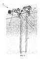
- FIGS. 1A and 1Bare perspective views of an example device constructed in accordance with the present disclosure.
- FIG. 2is a cross sectional view of an example device constructed in accordance with the present disclosure.
- the example devicecomprises a waveguide of transitional cross section along its length, and having both a polygonal cross sectional area and a cylindrical cross sectional area. This waveguide is incorporated into a reflector antenna.
- FIG. 3is a top down view of an example device constructed in accordance with the present disclosure.
- FIG. 4is a cross sectional assembly view of an example device constructed in accordance with the present disclosure.
- FIG. 5is a perspective view of an example device constructed in accordance with the present disclosure.
- FIG. 6is a top down view of an example device constructed in accordance with the present disclosure.
- the present disclosureprovides higher polarization isolation solutions for waveguides that are mounted directly to a printed circuit board (PCB) or otherwise coupled to the PCB.
- the present disclosureutilizes one or more cross sections of a given waveguide to ease signal transition.
- Waveguidescan have any variety of geometrical shapes and cross sections.
- the shape and/or cross section of a waveguidecan be continuous along its length or can vary according to various design requirements. For instance, cross sections can be polygonal, conical, cylindrical, rectangular, elliptical square or circular, just to name a few.
- the current practiceis to excite a waveguide with a probe or monopole antenna.
- the probecan be a wire attached to a coaxial transmission or a feature embedded in a PCB.
- a PCBcan be created with probes on the circuit board.
- a waveguideis then mounted directly to the PCB at approximately 90 degrees.
- the present disclosureprovides a polygonal (square) waveguide as a transition region before the circular waveguide to improve isolation compared to what is practical with co-planar probes in a circular waveguide.
- fields in a square waveguideare constrained to remain perpendicular to the waveguide walls and thus are not as free to change orientation as if they would be in a circular waveguide.
- the introduction of a square waveguide cross sectional area as a transitiongreatly improves the signal isolation that can be realized.
- coplanar probes in a circular waveguidetypically achieve ⁇ 20 dB of isolation. With a square waveguide cross sectional area, signal isolation can increased to ⁇ 40 dB and the signals can be much more clearly separated.
- the present disclosureprovides three noteworthy features.
- the methods and systems described hereinprovide improved higher polarization isolation, which allows for better separation of two signals as they are transmitted in space. In other words, the two signals will interact with each other less.
- higher isolation of approximately ⁇ 40 dBis achieved using the embodiments of this present disclosure, which is a 100 times improvement from the current practice of ⁇ 20 dB. Further details regarding this improvement will be discussed later herein.
- the present disclosureprovides an improved matching with the addition of dialectic material (such as in a dielectric block) around the PCB launch. That is, the process works better than conventional processes because there is a gentler transition of sending signals out of the PCB launched in the waveguide and reinjecting them.
- the dielectric blockcan be a matching component of the waveguide where it is used at the circular cross sectional area and the square cross sectional area of the waveguide.
- the dielectric blockcan be a matching component of the waveguide to match the PCB and the waveguide interface.
- various probescould be used, either in 3D or as shapes printed on a PCB.
- the dielectric fillingdoes not need to be present.
- dielectric fillingcan be used to support 3D probes.
- the dielectric blockis more convenient when it comes to precisely positioning probes inside the waveguide, which is occasionally used as a technique to supply and launch signals into the waveguide.
- the probesare made of wire which are soldered directly onto the circuit board and pressed in with the dielectric block.
- the probescould have a flatten replica right on the PCB itself. Instead of a rod shaped probe, it may be a flat piece of conductor built on the PCB.
- the probecan be included on the PCB on a two dimensional sheet rather than a three dimensional rod. An example of this can be viewed in FIG. 6 , discussed below.
- a waveguidehas a first cross sectional area and a second cross sectional area.
- the first cross sectional area and the second cross sectional areadiffer from each other.
- These cross sectionsmay have different shapes, forms, types, or configurations.
- the signal transitionmay be easier and less abrupt.
- FIGS. 1A and 1Bdepict an example device 100 that is constructed in accordance with the present disclosure. Specifically, these figures depict the transition where the signals are led either on or off of the PCB into the structure for the antenna (not shown).
- the device 100comprises a waveguide having a circular (cylindrical) waveguide cross sectional area 110 and a square transition waveguide cross sectional area 120 .
- the square transition waveguide cross-sectional area 120may also include one or more connectors.
- the device 100can include additional or fewer components than those illustrated.
- the coaxial connectorscan launch signals into the PCB (not shown in FIGS. 1A and 1B ).
- the PCBis preferably sandwiched between the circular waveguide cross sectional area 110 and the square transition waveguide cross sectional 120 .
- a more detailed view of thiscan be found in the assembly view provided in FIG. 4 , which shows a PCB 420 is sandwiched in between the circular waveguide cross sectional area 110 and the square transition waveguide cross sectional 120 . Further details regarding FIG. 4 and the particular components of the device are provided later herein.
- a square aperturewhich can mate with a waveguide that has a circular aperture which has a sharp edge.
- a conical shaped piece 124 of dielectric in that areais used to smooth the transition.
- the present disclosureis directed to a device that transitions signals using a waveguide including a first cross sectional area and a second cross sectional area, the first and second cross sectional areas differing from either other.
- the first cross sectional areashas a circular or cylindrical configuration and the second waveguide has a polygonal or square configuration.
- the waveguidecan comprise two sections of different size and/or cross section from one another.
- FIG. 2provides a cross sectional view of an example device 200 constructed in accordance with the present disclosure.
- the device 200comprises an integrated antenna, radio, and transceiver both for transmitting and receiving data signals.
- the device 200can be a 24 GHz back-haul radio.
- the device 200can communicate with a similar device located miles away.
- the antennais approximately 255 mm in diameter and is coupled with two printed circuit transmission lines (i.e. feed strips).
- the use of two feed lines (or feed lines and coaxial cables)allows for dual linear (or dual circular) polarization. Additional feeds could be used to excite multiple, higher order modes in a particular waveguide. Indeed, feed lines/strips as well as coaxial cables as described herein can be generally referred to as an electrical feed.
- the waveguidecontains radiation produced by the antenna and directs the radiation along a path that is coaxial with a centerline X of the waveguide, in some embodiments.
- the antennais coupled with a coaxial cable to a signal source such as a radio.
- the antennais coupled to a radio with a PCB based transmission line or feed strip.
- the coaxial cableis used in place of the feed strip.
- the coaxial cableis used in combination with one or more feed strips.
- the feed stripcan comprise a printed circuit transmission line, in some embodiments.
- the device 200provides high levels of signal isolation between adjacent feeds, in various embodiments.
- the device 200can also allow for linear or circular waves to be easily directed as desired.
- a narrow or wide bandwidth transitioncan be utilized, in some embodiments.
- the waveguide of the device 200can direct energy out onto the curved surface that is a parabolic reflector 210 .
- the dielectric substratecan comprise any suitable PCB (printed circuit board) substrate material constructed from, for example, one or more dielectric materials.
- the antennais mounted onto the dielectric substrate. In one embodiment the antenna is a patch antenna. In another embodiment, the antenna is a multi-stack set of antennas. In some embodiments, the antenna is electrically coupled with one or more printed circuit transmission lines.
- the example device 200comprises a waveguide of transitional cross section along its length.
- the waveguide depictedhas both a polygonal cross sectional 220 area and a cylindrical cross sectional area 230 .
- the waveguide of FIG. 2has a first section that has a polygonal cross section and a second section that has a cylindrical cross section.
- a transition section 240couples the first section and the second section of the waveguide.
- the transition section 240allows the shape of the signal radiation that is emitted to be changed.
- the transition section 240can be in the form of a square 220 with a conical shape mounted on it or otherwise coupled to it, while the waveguide includes a circular cross sectional area 230 , such as illustrated in FIG. 2 .
- the square 220is tapered into a conical shape, and allowed to gradually decrease until it disappears. This is the area where there is a transition between the propagation the polygonal cross sectional 220 area in relation to the cylindrical cross sectional area 230 .
- the square 220can be a dialectic block to ease the transition from the PCB into the waveguide, and also further down, the dielectric block can be used to ease the transition between the square waveguide cross sectional area 220 and the circular waveguide cross sectional area 230 . This allows for optimum radiation reflection and symmetry near the antenna, while providing a desired emitted signal shape through the transition section 240 .
- the waveguidecontains radiation produced by the antenna and directs the radiation along a path that is coaxial with a centerline X of the waveguide, in some embodiments.
- the waveguideis generally elongated, the waveguide can comprise a truncated or short embodiment of a waveguide.
- the antennawithout the waveguide, the antenna emits signal radiation in a plurality of directions, causing loss of signal strength, reduced signal directionality, as well as cross-port interference (e.g., where an adjacent antenna is affected by the antenna).
- the waveguide of the device 200is mounted directly to the dielectric substrate 250 , around a periphery of the antenna.
- the spacing between the waveguide and the antennacan be varied according to design parameters.
- the waveguideencloses the antenna and captures the radiation of the antenna, directing it along and out of the waveguide.
- the waveguideis constructed from any suitable conductive material. The use of the waveguide allows one to transfer signals from one location to another location with minimal loss or disturbance of the signal.
- the length of the waveguideis selected according to design requirements, such as required signal symmetry.
- the waveguidecan have any desired shape and/or size and length.
- the illustrated waveguideis circular in shape, but any polygonal, cylindrical, or irregular shape can be implemented as desired.
- the selection of dielectric materials for the waveguidecan be used to effectively adjust a physical size of components of the device 200 while keeping the electrical characteristics compatible.
- a wavelength in dielectricmakes objects smaller than they would be in a vacuum so the components or parts of the device 100 may shrink in size.
- the transitionis eased to ensure a gentler, less abrupt transition. In other words, this results in a less abrupt change in the propagation characteristics resulting in fewer reflections and less interference as they move throughout the device.
- the present disclosurealso includes embodiments where the device includes multiple dielectric pieces in different cross sections of a waveguide, in order to ease signal transition. If the signal hits the transition the amount of energy reflected in that transition corresponds to how much the dielectric constant changes on one side of the transition in comparison to the other side. Thus, the reflections are much reduced if signals experience propagation changes through are a plurality of smaller steps instead of one big step.
- the reflections of one transitioncan be arranged to cancel the reflections from a subsequent reflection.
- the conical shape mounted onto the square transition cross section areacould vary in length, be it longer or shorter.
- the conical shapehas a flat end with which one could control the magnitude and direction of a reflection in such a way that it cancels all the other reflections.
- the conical shapecan be used as a tuning tool to cancel other reflections, which is an improvement above the current practice.
- FIG. 3is exemplary view of the device 300 which provides an enlarged, more detailed perspective view of a portion of FIG. 2 .
- FIG. 3depicts a waveguide having a circular waveguide cross sectional area 330 and a square transition waveguide cross sectional area 320 comprising a dielectric block 322 .
- the square transition waveguide cross sectional area 320may include a conical shape with a tapered end 324 , which allows for the gentler transition of signals as they pass through the waveguide cross sectional areas which differ from each other. The gentler transition of signals in turn provides higher isolation.
- the device 300also includes two coaxial connectors 340 to the PCB. The device 300 is not limited to the number of components as depicted in FIG. 3 .
- FIG. 4is a cross sectional assembly view of a device 400 .
- FIG. 4shows a printed circuit board (PCB) 420 that is sandwiched in between the circular waveguide cross sectional area 110 and the square transition waveguide cross sectional area 120 .
- PCBprinted circuit board
- the device 400also comprises a top layer 410 and a bottom layer 430 which hold the assembly of the PCB and the components of the device 400 together.
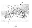
- FIG. 5is a perspective view of an example device 500 in accordance with some embodiments of the present disclosure.
- the device 500comprises a waveguide having a circular (cylindrical) waveguide cross sectional area 110 and a square transition waveguide cross sectional area 120 .
- the square transition section 120may include a square waveguide cross sectional area 522 with a conical shape waveguide cross section 524 mounted on it or otherwise coupled to it.
- the square transition waveguide cross-sectional area 120may also include one or more connectors 540 .
- the device 500can include additional or fewer components than those illustrated.
- the coaxial connectors 540are connectors to the PCB, and they can launch signals into the PCB (not shown in FIGS. 1A and 1B ).
- the PCBis preferably sandwiched between the circular waveguide cross sectional area 110 and the square transition waveguide cross sectional area 120 .
- FIG. 6is a top down view of a dielectric substrate 600 in accordance with some embodiments of the present disclosure.
- probescan be printed on a printed circuit board as depicted in FIG. 6 . It should be noted that for purposes of the present disclosure, wider probes having a triangular shape or a squatty appearance can have much more bandwidth than a skinny probe at the same overall length.
- the addition of dielectric materialcould be applied to a coaxial feed transmission, thereby eliminating the need for a PCB altogether.
- a coaxial feed transmissioninstead of having coaxial transmissions that interface and transition signals into a PCB, one could bring a coaxial cable up through the wall of the waveguide, put it with a different connector for the dielectric substrate, strip out the PCB and show the connector.
- first, second, etc.may be used herein to describe various elements, components, regions, layers and/or sections, these elements, components, regions, layers and/or sections should not necessarily be limited by such terms. These terms are only used to distinguish one element, component, region, layer or section from another element, component, region, layer or section. Thus, a first element, component, region, layer or section discussed below could be termed a second element, component, region, layer or section without departing from the teachings of the present disclosure.
- Example embodiments of the present disclosureare described herein with reference to illustrations of idealized embodiments (and intermediate structures) of the present disclosure. As such, variations from the shapes of the illustrations as a result, for example, of manufacturing techniques and/or tolerances, are to be expected. Thus, the example embodiments of the present disclosure should not be construed as necessarily limited to the particular shapes of regions illustrated herein, but are to include deviations in shapes that result, for example, from manufacturing.
- Any and/or all elements, as disclosed herein,can be formed from a same, structurally continuous piece, such as being unitary, and/or be separately manufactured and/or connected, such as being an assembly and/or modules. Any and/or all elements, as disclosed herein, can be manufactured via any manufacturing processes, whether additive manufacturing, subtractive manufacturing and/or other any other types of manufacturing. For example, some manufacturing processes include three dimensional (3D) printing, laser cutting, computer numerical control (CNC) routing, milling, pressing, stamping, vacuum forming, hydroforming, injection molding, lithography and/or others.
- 3Dthree dimensional
- CNCcomputer numerical control
- any and/or all elements, as disclosed herein,can include, whether partially and/or fully, a solid, including a metal, a mineral, a ceramic, an amorphous solid, such as glass, a glass ceramic, an organic solid, such as wood and/or a polymer, such as rubber, a composite material, a semiconductor, a nano-material, a biomaterial and/or any combinations thereof.
- a solidincluding a metal, a mineral, a ceramic, an amorphous solid, such as glass, a glass ceramic, an organic solid, such as wood and/or a polymer, such as rubber, a composite material, a semiconductor, a nano-material, a biomaterial and/or any combinations thereof.
- any and/or all elements, as disclosed herein,can include, whether partially and/or fully, a coating, including an informational coating, such as ink, an adhesive coating, a melt-adhesive coating, such as vacuum seal and/or heat seal, a release coating, such as tape liner, a low surface energy coating, an optical coating, such as for tint, color, hue, saturation, tone, shade, transparency, translucency, non-transparency, luminescence, anti-reflection and/or holographic, a photo-sensitive coating, an electronic and/or thermal property coating, such as for passivity, insulation, resistance or conduction, a magnetic coating, a water-resistant and/or waterproof coating, a scent coating and/or any combinations thereof.
- a coatingincluding an informational coating, such as ink, an adhesive coating, a melt-adhesive coating, such as vacuum seal and/or heat seal, a release coating, such as tape liner, a low surface energy coating, an optical coating, such as for tint, color, hue
- relative termssuch as “below,” “lower,” “above,” and “upper” may be used herein to describe one element's relationship to another element as illustrated in the accompanying drawings. Such relative terms are intended to encompass different orientations of illustrated technologies in addition to the orientation depicted in the accompanying drawings. For example, if a device in the accompanying drawings is turned over, then the elements described as being on the “lower” side of other elements would then be oriented on “upper” sides of the other elements. Similarly, if the device in one of the figures is turned over, elements described as “below” or “beneath” other elements would then be oriented “above” the other elements. Therefore, the example terms “below” and “lower” can, therefore, encompass both an orientation of above and below.
Landscapes
- Waveguide Aerials (AREA)
- Waveguides (AREA)
Abstract
Description
Claims (17)
Priority Applications (3)
| Application Number | Priority Date | Filing Date | Title |
|---|---|---|---|
| US15/863,059US10511074B2 (en) | 2018-01-05 | 2018-01-05 | Higher signal isolation solutions for printed circuit board mounted antenna and waveguide interface |
| PCT/US2019/012358WO2019136257A1 (en) | 2018-01-05 | 2019-01-04 | Higher signal isolation solutions for printed circuit board mounted antenna and waveguide interface |
| US16/669,383US10714805B2 (en) | 2018-01-05 | 2019-10-30 | Higher signal isolation solutions for printed circuit board mounted antenna and waveguide interface |
Applications Claiming Priority (1)
| Application Number | Priority Date | Filing Date | Title |
|---|---|---|---|
| US15/863,059US10511074B2 (en) | 2018-01-05 | 2018-01-05 | Higher signal isolation solutions for printed circuit board mounted antenna and waveguide interface |
Related Child Applications (1)
| Application Number | Title | Priority Date | Filing Date |
|---|---|---|---|
| US16/669,383ContinuationUS10714805B2 (en) | 2018-01-05 | 2019-10-30 | Higher signal isolation solutions for printed circuit board mounted antenna and waveguide interface |
Publications (2)
| Publication Number | Publication Date |
|---|---|
| US20190214699A1 US20190214699A1 (en) | 2019-07-11 |
| US10511074B2true US10511074B2 (en) | 2019-12-17 |
Family
ID=67141162
Family Applications (2)
| Application Number | Title | Priority Date | Filing Date |
|---|---|---|---|
| US15/863,059ActiveUS10511074B2 (en) | 2018-01-05 | 2018-01-05 | Higher signal isolation solutions for printed circuit board mounted antenna and waveguide interface |
| US16/669,383ActiveUS10714805B2 (en) | 2018-01-05 | 2019-10-30 | Higher signal isolation solutions for printed circuit board mounted antenna and waveguide interface |
Family Applications After (1)
| Application Number | Title | Priority Date | Filing Date |
|---|---|---|---|
| US16/669,383ActiveUS10714805B2 (en) | 2018-01-05 | 2019-10-30 | Higher signal isolation solutions for printed circuit board mounted antenna and waveguide interface |
Country Status (2)
| Country | Link |
|---|---|
| US (2) | US10511074B2 (en) |
| WO (1) | WO2019136257A1 (en) |
Cited By (14)
| Publication number | Priority date | Publication date | Assignee | Title |
|---|---|---|---|---|
| US10595253B2 (en) | 2013-02-19 | 2020-03-17 | Mimosa Networks, Inc. | Systems and methods for directing mobile device connectivity |
| US10616903B2 (en) | 2014-01-24 | 2020-04-07 | Mimosa Networks, Inc. | Channel optimization in half duplex communications systems |
| US10714805B2 (en) | 2018-01-05 | 2020-07-14 | Milmosa Networks, Inc. | Higher signal isolation solutions for printed circuit board mounted antenna and waveguide interface |
| US10742275B2 (en) | 2013-03-07 | 2020-08-11 | Mimosa Networks, Inc. | Quad-sector antenna using circular polarization |
| US10749263B2 (en) | 2016-01-11 | 2020-08-18 | Mimosa Networks, Inc. | Printed circuit board mounted antenna and waveguide interface |
| US10790613B2 (en) | 2013-03-06 | 2020-09-29 | Mimosa Networks, Inc. | Waterproof apparatus for pre-terminated cables |
| US10812994B2 (en) | 2013-03-08 | 2020-10-20 | Mimosa Networks, Inc. | System and method for dual-band backhaul radio |
| US10863507B2 (en) | 2013-02-19 | 2020-12-08 | Mimosa Networks, Inc. | WiFi management interface for microwave radio and reset to factory defaults |
| US10938110B2 (en) | 2013-06-28 | 2021-03-02 | Mimosa Networks, Inc. | Ellipticity reduction in circularly polarized array antennas |
| US10958332B2 (en) | 2014-09-08 | 2021-03-23 | Mimosa Networks, Inc. | Wi-Fi hotspot repeater |
| US11069986B2 (en) | 2018-03-02 | 2021-07-20 | Airspan Ip Holdco Llc | Omni-directional orthogonally-polarized antenna system for MIMO applications |
| US11251539B2 (en) | 2016-07-29 | 2022-02-15 | Airspan Ip Holdco Llc | Multi-band access point antenna array |
| US11289821B2 (en) | 2018-09-11 | 2022-03-29 | Air Span Ip Holdco Llc | Sector antenna systems and methods for providing high gain and high side-lobe rejection |
| US11888589B2 (en) | 2014-03-13 | 2024-01-30 | Mimosa Networks, Inc. | Synchronized transmission on shared channel |
Families Citing this family (1)
| Publication number | Priority date | Publication date | Assignee | Title |
|---|---|---|---|---|
| US9295103B2 (en) | 2013-05-30 | 2016-03-22 | Mimosa Networks, Inc. | Wireless access points providing hybrid 802.11 and scheduled priority access communications |
Citations (272)
| Publication number | Priority date | Publication date | Assignee | Title |
|---|---|---|---|---|
| US2735993A (en) | 1956-02-21 | humphrey | ||
| US3182129A (en) | 1965-05-04 | Clark etalelectronic stethoscope | ||
| US4188633A (en) | 1978-01-26 | 1980-02-12 | Hazeltine Corporation | Phased array antenna with reduced phase quantization errors |
| US4402566A (en) | 1981-10-13 | 1983-09-06 | International Telephone & Telegraph Corporation | Field repairable electrical connector |
| USD273111S (en) | 1981-02-09 | 1984-03-20 | Canon Kabushiki Kaisha | Combined data input terminal and acoustic coupler |
| US4543579A (en) | 1983-03-29 | 1985-09-24 | Radio Research Laboratories, Ministry Of Posts And Telecommunications | Circular polarization antenna |
| US4562416A (en) | 1984-05-31 | 1985-12-31 | Sanders Associates, Inc. | Transition from stripline to waveguide |
| US4626863A (en) | 1983-09-12 | 1986-12-02 | Andrew Corporation | Low side lobe Gregorian antenna |
| US4835538A (en) | 1987-01-15 | 1989-05-30 | Ball Corporation | Three resonator parasitically coupled microstrip antenna array element |
| US4866451A (en) | 1984-06-25 | 1989-09-12 | Communications Satellite Corporation | Broadband circular polarization arrangement for microstrip array antenna |
| US4893288A (en) | 1986-12-03 | 1990-01-09 | Deutsche Thomson-Brandt Gmbh | Audible antenna alignment apparatus |
| US4903033A (en) | 1988-04-01 | 1990-02-20 | Ford Aerospace Corporation | Planar dual polarization antenna |
| US4986764A (en) | 1989-10-31 | 1991-01-22 | Amp Incorporated | High voltage lead assembly and connector |
| US5015195A (en) | 1990-03-13 | 1991-05-14 | Thomas & Betts Corporation | Plug and socket electrical connection assembly |
| US5226837A (en) | 1990-11-16 | 1993-07-13 | Raychem Corporation | Environmentally protected connection |
| US5231406A (en) | 1991-04-05 | 1993-07-27 | Ball Corporation | Broadband circular polarization satellite antenna |
| USD346598S (en) | 1992-04-28 | 1994-05-03 | Coherent Communications Systems Corporation | Transceiver module for a table-top teleconferencing system |
| US5389941A (en) | 1992-02-28 | 1995-02-14 | Hughes Aircraft Company | Data link antenna system |
| USD355416S (en) | 1994-02-14 | 1995-02-14 | Coherent Communications Systems Corporation | Transceiver module for a table-top teleconferencing system |
| US5491833A (en) | 1993-12-27 | 1996-02-13 | Nec Corporation | Mobile radio communication system having radio zones of sector configurations and antenna selecting method employed therein |
| US5513380A (en) | 1992-09-23 | 1996-04-30 | Siemens Aktiengesellschaft | Mobile speed dependent handover techniques in hierarchical mobile radio networks |
| US5539361A (en) | 1995-05-31 | 1996-07-23 | The United States Of America As Represented By The Secretary Of The Air Force | Electromagnetic wave transfer |
| US5561434A (en) | 1993-06-11 | 1996-10-01 | Nec Corporation | Dual band phased array antenna apparatus having compact hardware |
| USD375501S (en) | 1994-01-28 | 1996-11-12 | American Phone Products, Inc. | Cup receptacle for telephone hand set |
| US5580264A (en) | 1994-08-09 | 1996-12-03 | Sumitomo Wiring Systems, Ltd. | Waterproofed connector |
| US5684495A (en) | 1995-08-30 | 1997-11-04 | Andrew Corporation | Microwave transition using dielectric waveguides |
| USD389575S (en) | 1996-10-22 | 1998-01-20 | Grasfield James A | Chestpiece of a stethoscope |
| US5724666A (en) | 1994-03-24 | 1998-03-03 | Ericsson Inc. | Polarization diversity phased array cellular base station and associated methods |
| US5742911A (en) | 1992-10-03 | 1998-04-21 | Motorola, Inc. | Sectorized cellular radio base station antenna |
| US5746611A (en) | 1996-07-15 | 1998-05-05 | The Whitaker Corporation | Electrical connector seal cap assembly |
| US5764696A (en) | 1995-06-02 | 1998-06-09 | Time Domain Corporation | Chiral and dual polarization techniques for an ultra-wide band communication system |
| US5831582A (en) | 1994-09-01 | 1998-11-03 | Easterisk Star, Inc. | Multiple beam antenna system for simultaneously receiving multiple satellite signals |
| US5966102A (en) | 1995-12-14 | 1999-10-12 | Ems Technologies, Inc. | Dual polarized array antenna with central polarization control |
| US6014372A (en) | 1997-12-08 | 2000-01-11 | Lockheed Martin Corp. | Antenna beam congruency system for spacecraft cellular communications system |
| US6137449A (en) | 1996-09-26 | 2000-10-24 | Kildal; Per-Simon | Reflector antenna with a self-supported feed |
| US6140962A (en) | 1998-04-29 | 2000-10-31 | Hollandse Signaalapparaten B.V. | Antenna system |
| US6176739B1 (en) | 1997-02-20 | 2001-01-23 | The Whitaker Corporation | Sealed electrical conductor assembly |
| US6216266B1 (en) | 1999-10-28 | 2001-04-10 | Hughes Electronics Corporation | Remote control signal level meter |
| US6271802B1 (en) | 1997-04-14 | 2001-08-07 | Mems Optical, Inc. | Three dimensional micromachined electromagnetic device and associated methods |
| US6304762B1 (en) | 1996-12-23 | 2001-10-16 | Texas Instruments Incorporated | Point to multipoint communication system with subsectored upstream antennas |
| US20010033600A1 (en) | 2000-02-28 | 2001-10-25 | Golden Bridge Technology Inc. | Sectorized smart antenna system and method |
| USD455735S1 (en) | 1999-12-30 | 2002-04-16 | Telaxis Communications Corporation | Subscriber premises transceiver for a local multi-point distribution service |
| US6421538B1 (en) | 1993-12-22 | 2002-07-16 | Nokia Mobile Phones, Limited | Multi-mode radio telephone with velocity sensing mode selection |
| US20020102948A1 (en) | 2000-09-14 | 2002-08-01 | Stanwood Kenneth L. | System and method for wireless communication in a frequency division duplexing region |
| US20020159434A1 (en) | 2001-02-12 | 2002-10-31 | Eleven Engineering Inc. | Multipoint short range radio frequency system |
| US20030013452A1 (en) | 2001-07-13 | 2003-01-16 | Koninklijke Philips Electronics N.V. | Hierarchical cellular radio communication system |
| US20030027577A1 (en) | 2001-08-06 | 2003-02-06 | Metric Systems, Inc. | Wireless communication system control apparatus and method |
| US20030169763A1 (en) | 2002-03-07 | 2003-09-11 | Sunghyun Choi | Coexistence of stations capable of different modulation schemes in a wireless local area network |
| US20030224741A1 (en) | 2002-04-22 | 2003-12-04 | Sugar Gary L. | System and method for classifying signals occuring in a frequency band |
| US20030222831A1 (en) | 2002-05-31 | 2003-12-04 | Brian Dunlap | Three-dimensional spatial division multiplexing access (3D-SDMA) antenna system |
| US20040002357A1 (en) | 2002-06-25 | 2004-01-01 | Mathilde Benveniste | Directional antennas and wireless channel access |
| US20040029549A1 (en) | 2002-08-09 | 2004-02-12 | Fikart Josef Ludvik | Downconverter for the combined reception of linear and circular polarization signals from collocated satellites |
| US6716063B1 (en) | 2000-02-28 | 2004-04-06 | Pgs Exploration (Us), Inc. | Electrical cable insert |
| US20040110469A1 (en) | 2000-01-14 | 2004-06-10 | Judd Mano D. | Repeaters for wireless communication systems |
| US6754511B1 (en) | 2000-02-04 | 2004-06-22 | Harris Corporation | Linear signal separation using polarization diversity |
| US20040120277A1 (en) | 2002-11-18 | 2004-06-24 | Holur Balaji S. | Method and system for service portability across disjoint wireless networks |
| US20040196813A1 (en) | 2003-04-07 | 2004-10-07 | Yoram Ofek | Multi-sector antenna apparatus |
| US20040196812A1 (en) | 2003-04-07 | 2004-10-07 | Instant802 Networks Inc. | Multi-band access point with shared processor |
| US20040240376A1 (en) | 2003-05-30 | 2004-12-02 | Agency For Science, Technology And Research | Method for reducing channel estimation error in an OFDM system |
| US20040242274A1 (en) | 2003-05-30 | 2004-12-02 | Corbett Christopher J. | Using directional antennas to mitigate the effects of interference in wireless networks |
| US6847653B1 (en) | 1999-11-09 | 2005-01-25 | Interwave Communications International, Ltd. | Protocol for voice and data priority virtual channels in a wireless local area networking system |
| US20050032479A1 (en) | 2003-07-28 | 2005-02-10 | Miller Karl A. | Signal classification methods for scanning receiver and other applications |
| USD501848S1 (en) | 2003-07-14 | 2005-02-15 | Sony Corporation | Transmitter |
| US20050058111A1 (en) | 2003-09-15 | 2005-03-17 | Pai-Fu Hung | WLAN device having smart antenna system |
| US6877277B2 (en) | 2000-12-10 | 2005-04-12 | Tiefenbach Bergbautechnik Gmbh | Coupling for explosion-proof connection of two electric line ends |
| US20050124294A1 (en) | 2003-11-17 | 2005-06-09 | Conextant Systems, Inc. | Wireless access point simultaneously supporting basic service sets on multiple channels |
| US20050143014A1 (en) | 2003-12-29 | 2005-06-30 | Intel Corporation | Antenna subsystem calibration apparatus and methods in spatial-division multiple-access systems |
| US20050195758A1 (en) | 2004-03-05 | 2005-09-08 | Interdigital Technology Corporation | Full duplex communication system using disjoint spectral blocks |
| US20050227625A1 (en) | 2004-03-25 | 2005-10-13 | Diener Neil R | User interface and time-shifted presentation of data in a system that monitors activity in a shared radio frequency band |
| US6962445B2 (en) | 2003-09-08 | 2005-11-08 | Adc Telecommunications, Inc. | Ruggedized fiber optic connection |
| US20050254442A1 (en) | 2004-05-13 | 2005-11-17 | Widefi, Inc. | Non-frequency translating repeater with detection and media access control |
| US20050271056A1 (en) | 2004-05-17 | 2005-12-08 | Matsushita Electronic Industrial Co., Ltd | Packet generation method, communication method, packet processing method and data structure |
| US20050275527A1 (en) | 2004-05-27 | 2005-12-15 | Lawrence Kates | Wireless repeater for sensor system |
| US20060025072A1 (en) | 2004-07-29 | 2006-02-02 | Lucent Technologies, Inc. | Extending wireless communication RF coverage inside building |
| US20060072518A1 (en) | 2000-07-10 | 2006-04-06 | Interdigital Technology Corporation | Code power measurement for dynamic channel allocation |
| US20060098592A1 (en) | 2002-12-16 | 2006-05-11 | Widefi, Inc. | Wireless network repeater |
| US20060099940A1 (en) | 2004-11-10 | 2006-05-11 | Pfleging Gerald W | Method for changing the status of a mobile apparatus |
| US20060132602A1 (en) | 2003-06-12 | 2006-06-22 | Denso Corporation | Image server, image acquisition device, and image display terminal |
| US20060132359A1 (en) | 2004-12-22 | 2006-06-22 | Tatung Co., Ltd. | Circularly polarized array antenna |
| US7075492B1 (en) | 2005-04-18 | 2006-07-11 | Victory Microwave Corporation | High performance reflector antenna system and feed structure |
| US20060172578A1 (en) | 2005-02-03 | 2006-08-03 | Pacific Wireless Manufacturing, Inc. | Low-cost weatherproof cable feedthrough |
| US20060187952A1 (en) | 2005-02-18 | 2006-08-24 | Avaya Technology Corp. | Methods and systems for providing priority access to 802.11 endpoints using DCF protocol |
| US20060211430A1 (en) | 2005-03-17 | 2006-09-21 | Persico Charles J | GPS position tracking method with variable updating rate for power conservation |
| USD533899S1 (en) | 2003-09-18 | 2006-12-19 | Riso Kagaku Corporation | Hub for a printing paper roll |
| US20070001910A1 (en) | 2003-12-18 | 2007-01-04 | Fujitsu Limited | Antenna device, radio-wave receiver and radio-wave transmitter |
| US20070019664A1 (en) | 2000-11-03 | 2007-01-25 | At&T Corp. | Tiered contention multiple access (TCMA): a method for priority-based shared channel access |
| US7173570B1 (en) | 2004-07-12 | 2007-02-06 | Wensink Jan B | Cell phone tower antenna tilt and heading control |
| US20070035463A1 (en) | 2005-06-03 | 2007-02-15 | Sony Corporation | Antenna device, wireless communication apparatus using the same, and control method of controlling wireless communication apparatus |
| US7187328B2 (en) | 2002-10-25 | 2007-03-06 | National Institute Of Information And Communications Technology, Incorporated Administrative Agency | Antenna device |
| US20070060158A1 (en) | 2005-02-04 | 2007-03-15 | Toshiba American Research, Inc. | Channel partitioning forwireless local area networks |
| US7193562B2 (en) | 2004-11-22 | 2007-03-20 | Ruckus Wireless, Inc. | Circuit board having a peripheral antenna apparatus with selectable antenna elements |
| US7212162B2 (en) | 2003-11-22 | 2007-05-01 | Electronics And Telecommunications Research Institute | Horn antenna for circular polarization using planar radiator |
| US7212163B2 (en) | 2004-02-11 | 2007-05-01 | Sony Deutschland Gmbh | Circular polarized array antenna |
| EP1384285B1 (en) | 2001-04-11 | 2007-06-13 | Kyocera Wireless Corp. | Ferroelectric antenna and method for tuning same |
| US20070132643A1 (en) | 2005-12-14 | 2007-06-14 | Harris Corporation | Dual polarization antenna array with inter-element coupling and associated methods |
| US7245265B2 (en) | 2004-07-20 | 2007-07-17 | Vega Grieshaber Kg | Parabolic antenna of a level measuring instrument and level measuring instrument with a parabolic antenna |
| US20070173260A1 (en) | 2006-01-23 | 2007-07-26 | Love Robert T | Wireless communication network scheduling |
| US20070173199A1 (en) | 2006-01-13 | 2007-07-26 | Amit Sinha | Systems and methods for wireless intrusion detection using spectral analysis |
| US7253783B2 (en) | 2002-09-17 | 2007-08-07 | Ipr Licensing, Inc. | Low cost multiple pattern antenna for use with multiple receiver systems |
| US20070202809A1 (en) | 2006-02-28 | 2007-08-30 | Rotani, Inc. | Methods and apparatus for overlapping MIMO antenna physical sectors |
| US7264494B2 (en) | 2004-12-06 | 2007-09-04 | Weatherford/Lamb, Inc. | Electrical connector and socket assemblies |
| US20070210974A1 (en) | 2002-09-17 | 2007-09-13 | Chiang Bing A | Low cost multiple pattern antenna for use with multiple receiver systems |
| US20070223701A1 (en) | 2006-01-30 | 2007-09-27 | Motorola, Inc. | Method and apparatus for utilizing multiple group keys for secure communications |
| US20070238482A1 (en) | 2006-03-30 | 2007-10-11 | Giora Rayzman | Device, system and method of coordination among multiple transceivers |
| US7281856B2 (en) | 2005-08-15 | 2007-10-16 | Molex Incorporated | Industrial optical fiber connector assembly |
| US20070255797A1 (en) | 2006-04-28 | 2007-11-01 | Dunn Douglas L | Method for selecting an air interface using an access list on a multi-mode wireless device |
| US7292198B2 (en) | 2004-08-18 | 2007-11-06 | Ruckus Wireless, Inc. | System and method for an omnidirectional planar antenna apparatus with selectable elements |
| US20070268848A1 (en) | 2006-05-18 | 2007-11-22 | Qualcomm Incorporated | Half-duplex communication in a frequency division duplex system |
| US7306485B2 (en) | 2006-03-01 | 2007-12-11 | Hirose Electric Co., Ltd. | Waterproof device |
| US7324057B2 (en) | 2005-09-26 | 2008-01-29 | Gideon Argaman | Low wind load parabolic dish antenna fed by crosspolarized printed dipoles |
| USD566698S1 (en) | 2006-03-03 | 2008-04-15 | Lite-On Technology Corp. | Wireless network device |
| US7362236B2 (en) | 2004-12-06 | 2008-04-22 | Itron, Inc. | Mobile utility data collection system with voice technology, such as for data collection relating to an electric, gas, or water utility |
| US7369095B2 (en) | 2000-06-09 | 2008-05-06 | Thomson Licensing | Source-antennas for transmitting/receiving electromagnetic waves |
| US20080109051A1 (en) | 2006-11-06 | 2008-05-08 | Tim John Splinter | System and method for operating a wireless medical device interrogation network |
| US20080112380A1 (en) | 2006-11-10 | 2008-05-15 | Fischer Matthew J | Serial clear to send (cts) to self (cts2self) messaging procedure |
| US7380984B2 (en) | 2005-03-28 | 2008-06-03 | Tokyo Electron Limited | Process flow thermocouple |
| US20080192707A1 (en) | 2006-06-13 | 2008-08-14 | Texas Instruments Incorporated | Reducing collisions in beamforming wireless systems |
| US20080218418A1 (en) | 2007-03-05 | 2008-09-11 | Gillette Marlin R | Patch antenna including septa for bandwidth conrol |
| US20080231541A1 (en) | 2004-11-15 | 2008-09-25 | Tasuku Teshirogi | Circularly Polarized Antenna and Radar Device Using the Same |
| US20080242342A1 (en) | 2007-03-26 | 2008-10-02 | Broadcom Corporation | Rf filtering at very high frequencies for substrate communications |
| US7431602B2 (en) | 2005-04-21 | 2008-10-07 | Dsm & T Co., Inc. | Electrical connector |
| US20090046673A1 (en) | 2007-08-17 | 2009-02-19 | Oren Kaidar | Method and apparatus for improved dual channel operation and access point discovery in wireless communication networks |
| US20090052362A1 (en) | 2004-05-12 | 2009-02-26 | Meier Robert C | Power-save apparatus for 802.11 multicast paging applications |
| US7498996B2 (en) | 2004-08-18 | 2009-03-03 | Ruckus Wireless, Inc. | Antennas with polarization diversity |
| US7498896B2 (en) | 2007-04-27 | 2009-03-03 | Delphi Technologies, Inc. | Waveguide to microstrip line coupling apparatus |
| US20090059794A1 (en) | 2007-08-29 | 2009-03-05 | Skypilot Networks, Inc. | Method and apparatus for wiFi long range radio coordination |
| US20090075606A1 (en) | 2005-06-24 | 2009-03-19 | Victor Shtrom | Vertical multiple-input multiple-output wireless antennas |
| US7507105B1 (en) | 2007-07-17 | 2009-03-24 | Ventek, Llc | Hazardous area coupler device |
| US20090096699A1 (en) | 2007-10-16 | 2009-04-16 | The Hong Kong University Of Science And Technology | Compact 3-port orthogonally polarized mimo antennas |
| US7522095B1 (en) | 2005-07-15 | 2009-04-21 | Lockheed Martin Corporation | Polygonal cylinder array antenna |
| US7542717B2 (en) | 1995-02-22 | 2009-06-02 | Global Communications, Inc. | Satellite broadcast receiving and distribution system |
| US7581976B2 (en) | 2004-06-02 | 2009-09-01 | Gl Tool & Manufacturing Company Inc. | Bulkhead connector |
| US7586891B1 (en) | 2005-12-08 | 2009-09-08 | The United States Of America As Represented By The Secretary Of The Army | Communication network optimization tool |
| US20090232026A1 (en) | 2007-05-21 | 2009-09-17 | Arrowspan, Inc. | Multi-radio wireless mesh network solutions |
| US20090233475A1 (en) | 2008-03-11 | 2009-09-17 | Ametek Scp, Inc. | Waterproof gigabit ethernet connector |
| US7616959B2 (en) | 2004-07-19 | 2009-11-10 | Rotani, Inc. | Method and apparatus for shaped antenna radiation patterns |
| US20090291690A1 (en) | 2008-05-22 | 2009-11-26 | Ntt Docomo, Inc. | Femtocell Channel Assignment and Power Control for Improved Femtocell Coverage and Efficient Cell Search |
| US20090315792A1 (en) | 2006-08-03 | 2009-12-24 | Norihiro Miyashita | Antenna apparatus utilizing small loop antenna element having munute length and two feeding points |
| US20100029282A1 (en) | 2008-07-31 | 2010-02-04 | Qualcomm Incorporated | Resource partitioning in heterogeneous access point networks |
| US20100039340A1 (en) | 2007-10-19 | 2010-02-18 | Kenneth Brown | Rf waveform modulation apparatus and method |
| US20100046650A1 (en) | 2007-01-12 | 2010-02-25 | Joengren George | Method for Precoding Using a Block Diagonal Matrix |
| US7675473B2 (en) | 2005-10-14 | 2010-03-09 | Vega Grieshaber Kg | Parabolic antenna with rinsing connection |
| US20100067505A1 (en) | 2003-11-10 | 2010-03-18 | Yaron Fein | Performance of a Wireless Communication System |
| US20100085950A1 (en) | 2008-10-07 | 2010-04-08 | Masahiro Sekiya | Wireless communication device and wireless communication method |
| US20100091818A1 (en) | 2008-10-14 | 2010-04-15 | Sen Indranil S | Dynamic channel evaluation in wireless communication device |
| US20100103066A1 (en) | 2004-08-18 | 2010-04-29 | Victor Shtrom | Dual Band Dual Polarization Antenna Array |
| US20100103065A1 (en) | 2004-08-18 | 2010-04-29 | Victor Shtrom | Dual Polarization Antenna with Increased Wireless Coverage |
| US20100136978A1 (en) | 2008-12-03 | 2010-06-03 | Electronics And Telecommunications Research | Method for handoff of portable terminal between heterogeneous wireless networks |
| US20100151877A1 (en) | 2008-12-16 | 2010-06-17 | Seung-Hwan Lee | Smart radio communication system and method of operating the same |
| US20100167719A1 (en) | 2005-06-29 | 2010-07-01 | Koninklijke Philips Electronics N.V. | Method and apparatus for delegating signal quality handover measuring of a user equipment in wireless communication to a neighbouring user equipment |
| US20100171665A1 (en) | 2007-05-17 | 2010-07-08 | Omron Corporation | Array antenna |
| US20100171675A1 (en) | 2007-06-06 | 2010-07-08 | Carmen Borja | Dual-polarized radiating element, dual-band dual-polarized antenna assembly and dual-polarized antenna array |
| US20100189005A1 (en) | 2009-01-27 | 2010-07-29 | Bertani Torquato | Method for automatic selection of a mac protocol for a communication system and related system |
| US20100202613A1 (en) | 2009-01-07 | 2010-08-12 | Qualcomm Incorporated | Packet bundling at the pdcp layer with ciphering on the pdcp sdu |
| US20100210147A1 (en) | 2009-02-13 | 2010-08-19 | Itt Manufacturing Enterprises, Inc. | Connectors to connect electronic devices |
| US20100216412A1 (en) | 2009-02-26 | 2010-08-26 | Broadcom Corporation | Configurable transceiver and methods for use therewith |
| US20100225529A1 (en) | 2009-03-05 | 2010-09-09 | Southwest Research Institute | Unswitched, ultra low power, long range radar system |
| US20100238083A1 (en) | 2009-03-20 | 2010-09-23 | Rammohan Malasani | Long-distance wireless-lan directional antenna alignment |
| US20100315307A1 (en) | 2009-06-12 | 2010-12-16 | Andrew Llc | Radome and Shroud Enclosure for Reflector Antenna |
| US20100322219A1 (en) | 2009-06-05 | 2010-12-23 | Broadcom Corporation | Management frame directed cluster assignment within multiple user, multiple access, and/or MIMO wireless communications |
| US7857523B2 (en) | 2008-06-04 | 2010-12-28 | Hirose Electric Co., Ltd. | Waterproof connector having movable connector member and waterproof apparatus using the same |
| US20110006956A1 (en) | 2006-06-27 | 2011-01-13 | Mccown James Charles | Passive parabolic antenna, wireless communication system and method of boosting signal strength of a subscriber module antenna |
| US20110028097A1 (en) | 2009-07-29 | 2011-02-03 | Gokhan Memik | Hierarchical spectrum sensing for cognitive radios |
| US20110032159A1 (en) | 2009-08-04 | 2011-02-10 | Min-Chung Wu | Antenna Apparatus with Adaptive Polarization Switching Function |
| US20110044186A1 (en) | 2009-08-19 | 2011-02-24 | Samsung Electronics Co. Ltd. | Apparatus and method for adaptively generating channel quality indicator in wireless communication system |
| US7929914B2 (en) | 2004-03-31 | 2011-04-19 | The Invention Science Fund I, Llc | Mote networks using directional antenna techniques |
| US20110103309A1 (en) | 2009-10-30 | 2011-05-05 | Interdigital Patent Holdings, Inc. | Method and apparatus for concurrently processing multiple radio carriers |
| US20110112717A1 (en) | 2009-11-11 | 2011-05-12 | Benjamin Resner | Methods and Apparatus for Automatic Internet Logging and Social Comparison of Vehicular Driving Behavior |
| US20110111715A1 (en) | 2009-11-06 | 2011-05-12 | Viasat, Inc. | Outdoor unit installation aid feature |
| US20110133996A1 (en) | 2009-12-08 | 2011-06-09 | Motorola, Inc. | Antenna feeding mechanism |
| US20110170424A1 (en) | 2010-01-08 | 2011-07-14 | Saeid Safavi | Apparatus and methods for interference mitigation and coordination in a wireless network |
| US20110172916A1 (en) | 2010-01-14 | 2011-07-14 | Qualcomm Incorporated | Mobile Device Positioning In A Constrained Environment |
| US20110182277A1 (en) | 2005-12-29 | 2011-07-28 | Nir Shapira | Method, apparatus and system of spatial division multiple access communication in a wireless local area network |
| US20110182260A1 (en) | 2010-01-26 | 2011-07-28 | Georgia Tech Research Corporation | Systems and methods for achieving high data-rate wireless communication |
| US20110194644A1 (en) | 2010-02-10 | 2011-08-11 | Yong Liu | Transmission Protection For Wireless Communications |
| US20110206012A1 (en) | 2010-02-22 | 2011-08-25 | Sungkyunkwan University Foundation For Corporate Collaboration | Handover method and apparatus for providing mobile iptv service over heterogeneous wireless communication networks |
| US20110243291A1 (en) | 2010-03-31 | 2011-10-06 | Andrew Llc | Synchronous transfer of streaming data in a distributed antenna system |
| US20110241969A1 (en) | 2008-12-12 | 2011-10-06 | Nanyang Technological University | Grid array antennas and an integration structure |
| US20110256874A1 (en) | 2007-04-18 | 2011-10-20 | Masao Hayama | Handoff method between different systems and wireless terminal |
| US8069465B1 (en) | 2011-01-05 | 2011-11-29 | Domanicom Corp. | Devices, systems, and methods for managing multimedia traffic across a common wireless communication network |
| US20110291914A1 (en) | 2010-05-27 | 2011-12-01 | Andrew Llc | Segmented antenna reflector with shield |
| US20120008542A1 (en) | 2009-03-20 | 2012-01-12 | Luke Koleszar | Distributed Ad Hoc Mesh Network Protocol for Underground Mine and Hazardous Area Communications |
| US20120040700A1 (en) | 2010-02-12 | 2012-02-16 | Interdigital Patent Holdings, Inc. | Group paging for machine-type communications |
| US20120057533A1 (en) | 2010-09-03 | 2012-03-08 | Nokia Corporation | Resource sharing between secondary networks |
| US20120093091A1 (en) | 2010-10-17 | 2012-04-19 | Industrial Technology Research Institute | Method and system for extended service channel access on demand in an alternating wireless channel access environment |
| US20120115487A1 (en) | 2009-06-18 | 2012-05-10 | Nicolas Josso | Quality Control for Inter-Cell Handover |
| US20120134280A1 (en) | 2010-11-29 | 2012-05-31 | Rosemount, Inc. | Wireless sensor network access point and device rf spectrum analysis system and method |
| US20120140651A1 (en) | 2010-12-01 | 2012-06-07 | Deutsche Telekom Ag | System support for accessing and switching among multiple wireless interfaces on mobile devices |
| US20120238201A1 (en) | 2009-04-17 | 2012-09-20 | Lingna Holdings Pte., Llc | Exploiting multiple antennas for spectrum sensing in cognitive radio networks |
| US20120263145A1 (en) | 2011-04-13 | 2012-10-18 | Interdigital Patent Holdings, Inc | Method and apparatus for small cell discovery in heterogeneous networks |
| US20120282868A1 (en) | 2011-05-05 | 2012-11-08 | OMNI-WiFi, LLC | Pyramidal Antenna Apparatus |
| US20120299789A1 (en) | 2010-01-29 | 2012-11-29 | Daniel Orban | Circularly polarized antenna and feeding network |
| US20120314634A1 (en) | 2011-06-09 | 2012-12-13 | Symbol Technologies, Inc. | Client bridge between wired and wireless communication networks |
| US20130005350A1 (en) | 2011-06-30 | 2013-01-03 | Cable Television Laboratories, Inc. | Optimizing network access |
| US20130003645A1 (en) | 2011-06-15 | 2013-01-03 | Nir Shapira | Repeater for enhancing performance of a wireless lan network |
| USD674787S1 (en) | 2011-10-18 | 2013-01-22 | Yokogawa Electric Corporation | Field wireless access point |
| US20130023216A1 (en) | 2011-07-21 | 2013-01-24 | Microsoft Corporation | Cloud service for optimizing white-space networks coexistence |
| US20130064161A1 (en) | 2011-09-14 | 2013-03-14 | Cisco Technology, Inc. | Group Addressing for Multicast Transmissions for Power Savings at Physical Layer |
| US20130082899A1 (en) | 2011-09-30 | 2013-04-04 | Kabushiki Kaisha Toshiba | High-frequency line-waveguide converter |
| US20130095747A1 (en) | 2011-10-17 | 2013-04-18 | Mehran Moshfeghi | Method and system for a repeater network that utilizes distributed transceivers with array processing |
| US20130128858A1 (en) | 2010-08-04 | 2013-05-23 | Nokia Corporation | Resolution method and apparatus for simultaneous transmission and receiving contention in a device-to-device cellular reuse system |
| US8482478B2 (en) | 2008-11-12 | 2013-07-09 | Xirrus, Inc. | MIMO antenna system |
| US20130176902A1 (en) | 2012-01-09 | 2013-07-11 | Qualcomm Incorporated | System and method of communication using distributed channel access parameters |
| US20130182652A1 (en) | 2012-01-13 | 2013-07-18 | Fei Tong | Methods and apparatus in a wireless network |
| US20130195081A1 (en) | 2011-09-29 | 2013-08-01 | Qualcomm Incorporated | Collision reduction mechanisms for wireless communication networks |
| US20130210457A1 (en) | 2010-03-01 | 2013-08-15 | Andrew Llc | System and method for location of mobile devices in confined environments |
| US8515495B2 (en) | 2009-02-27 | 2013-08-20 | Nokia Siemens Networks Oy | MIMO communication system |
| US8515434B1 (en) | 2010-04-08 | 2013-08-20 | Sprint Spectrum L.P. | Methods and devices for limiting access to femtocell radio access networks |
| US20130223398A1 (en) | 2010-11-25 | 2013-08-29 | Nokia Corporation | Network assisted sensing on a shared band for local communications |
| US20130234898A1 (en) | 2012-03-06 | 2013-09-12 | City University Of Hong Kong | Aesthetic dielectric antenna and method of discretely emitting radiation pattern using same |
| US20130271319A1 (en) | 2012-04-12 | 2013-10-17 | Alan Trerise | Method and system for aiming and aligning self-installed broadcast signal receivers |
| US20130286959A1 (en) | 2012-04-30 | 2013-10-31 | Interdigital Patent Holdings, Inc. | Method and apparatus for supporting coordinated orthogonal block-based resource allocation (cobra) operations |
| US20130288735A1 (en) | 2011-01-07 | 2013-10-31 | Sony Corporation | System and method for wireless network management |
| US20130286950A1 (en) | 2010-12-06 | 2013-10-31 | ST-Ericsson Semiconductor (Beijing) Co. Ltd. | Method and Mobile Terminal for Dealing with PS Domain Service and Realizing PS Domain Service Request |
| US20130301438A1 (en) | 2012-05-11 | 2013-11-14 | Qinghua Li | Apparatus and method to establish a device-to-device (d2d) connection in a 3gpp-lte network using a distributed channel scan |
| USD694740S1 (en) | 2011-10-25 | 2013-12-03 | Costa Apostolakis | Wireless communications gateway |
| US20130322276A1 (en) | 2012-05-31 | 2013-12-05 | Interdigital Patent Holdings, Inc. | Device-to-device (d2d) link adaptation |
| US20130322413A1 (en) | 2012-05-31 | 2013-12-05 | Interdigital Patent Holdings, Inc. | Methods to enable scheduling and control of direct link communication in cellular communication systems |
| US20140024328A1 (en) | 2012-07-19 | 2014-01-23 | Tensorcom, Inc. | Method and Apparatus for the Alignment of a 60 GHz Endfire Antenna |
| US20140051357A1 (en) | 2011-02-25 | 2014-02-20 | Research In Motion Limited | Determining device in-range proximity |
| US20140098748A1 (en) | 2012-10-09 | 2014-04-10 | Cisco Technology, Inc. | Dynamic Bandwidth Selection for Wide Bandwidth Wireless Local Area Networks |
| US20140113676A1 (en) | 2011-05-06 | 2014-04-24 | Nokia Siemens Networks Oy | Arrangements for Controlling Antennas |
| US20140145890A1 (en) | 2012-11-27 | 2014-05-29 | Laird Technologies, Inc. | Antenna Assemblies Including Dipole Elements and Vivaldi Elements |
| US20140185494A1 (en) | 2011-12-27 | 2014-07-03 | Xue Yang | Method and system for coexistence of multiple collocated radios |
| US20140191918A1 (en) | 2013-01-07 | 2014-07-10 | Arcadyan Technology Corporation | Omnidirectional antenna |
| US8777660B2 (en) | 2011-07-26 | 2014-07-15 | Tyco Electronics Amp Italia Srl | Electric connector with a cable clamping portion |
| US20140198867A1 (en) | 2013-01-16 | 2014-07-17 | Broadcom Corporation | Communication System Having Cross Polarization Interference Cancellation (XPIC) |
| US20140206322A1 (en) | 2013-01-18 | 2014-07-24 | Telefonaktiebolaget L M Ericsson (Publ) | Network-assisted ue detection in direct mode ue-to-ue communication |
| US8792759B2 (en) | 2011-04-11 | 2014-07-29 | Advanced Fiber Products, LLC | Gigabit wet mate active cable |
| US20140225788A1 (en) | 2013-02-08 | 2014-08-14 | Ubiquiti Networks, Inc. | Radio system for long-range high speed wireless communication |
| US20140233613A1 (en) | 2013-02-19 | 2014-08-21 | Jaime Fink | WiFi Management Interface for Microwave Radio and Reset to Factory Defaults |
| US20140235244A1 (en) | 2013-02-19 | 2014-08-21 | Brian L. Hinman | Systems and Methods for Directing Mobile Device Connectivity |
| US8827729B2 (en) | 2010-04-09 | 2014-09-09 | Delphi International Operations Luxembourg S.A.R.L. | Electrical connector system |
| US20140256166A1 (en) | 2013-03-06 | 2014-09-11 | Mimosa Networks, Inc. | Waterproof Apparatus for Cables and Cable Interfaces |
| US20140253378A1 (en) | 2013-03-07 | 2014-09-11 | Brian L. Hinman | Quad-Sector Antenna Using Circular Polarization |
| US20140254700A1 (en) | 2013-03-08 | 2014-09-11 | Brian L. Hinman | System and Method for Dual-Band Backhaul Radio |
| US20140253402A1 (en) | 2013-03-06 | 2014-09-11 | Brian L. Hinman | Enclosure for Radio, Parabolic Dish Antenna, and Side Lobe Shields |
| US8836601B2 (en) | 2013-02-04 | 2014-09-16 | Ubiquiti Networks, Inc. | Dual receiver/transmitter radio devices with choke |
| US8848389B2 (en) | 2008-09-25 | 2014-09-30 | Sony Corporation | Transmission device and method for manufacturing same, and wireless transmission device and wireless transmission method |
| US8870069B2 (en) | 2012-08-22 | 2014-10-28 | Symbol Technologies, Inc. | Co-located antenna arrangement |
| US20140320306A1 (en) | 2011-11-24 | 2014-10-30 | Nisko Telematics 2012 Limited Partnership | Methods and systems of reading utility meters and methods and systems of transmitting utility meter data |
| US20140320377A1 (en) | 2013-04-27 | 2014-10-30 | Commsky Technologies, Inc. | Multi-channel multi-sector smart antenna system |
| US20140328238A1 (en) | 2011-11-24 | 2014-11-06 | Lg Electronics Inc. | Grouping-based data transceiving method in wireless lan system and apparatus for supporting same |
| US20140355578A1 (en) | 2013-05-30 | 2014-12-04 | Mimosa Networks, Inc. | Wireless Access Points Providing Hybrid 802.11 and Scheduled Priority Access Communications |
| WO2014193394A1 (en) | 2013-05-30 | 2014-12-04 | Mimosa Networks, Inc. | Wireless access points providing hybrid 802.11 and scheduled priority access communications |
| US20150002354A1 (en) | 2012-01-18 | 2015-01-01 | Thales Holdings Uk Plc | Horn antenna |
| US20150002335A1 (en) | 2013-06-28 | 2015-01-01 | Mimosa Networks, Inc. | Ellipticity reduction in circularly polarized array antennas |
| US8935122B2 (en) | 2010-12-03 | 2015-01-13 | US Tower Corp. | Alignment detection device |
| US20150015435A1 (en) | 2012-03-14 | 2015-01-15 | Zte (Usa) Inc. | Receiver signal strength indicator meter for automatic antenna alignment in indoor and outdoor mount applications |
| US9001689B1 (en) | 2014-01-24 | 2015-04-07 | Mimosa Networks, Inc. | Channel optimization in half duplex communications systems |
| US9019874B2 (en) | 2012-06-27 | 2015-04-28 | Nokia Corporation | Method, apparatus, and computer program product for resolving hidden node in synchronized DCF based channel access |
| US20150116177A1 (en) | 2013-10-29 | 2015-04-30 | Radio Frequency Systems, Inc. | Vertically And Horizontally Polarized Omnidirectional Antennas And Related Methods |
| US9077071B2 (en) | 2004-08-18 | 2015-07-07 | Ruckus Wireless, Inc. | Antenna with polarization diversity |
| US9107134B1 (en) | 2011-01-12 | 2015-08-11 | Sprint Communications Company L.P. | Edge sector handoff determination |
| US20150256275A1 (en) | 2014-03-05 | 2015-09-10 | Mimosa Networks, Inc. | System and method for aligning a radio using an automated audio guide |
| US20150263816A1 (en) | 2014-03-13 | 2015-09-17 | Mimosa Networks, Inc. | Simultaneous transmission on shared channel |
| US20150321017A1 (en) | 2014-05-12 | 2015-11-12 | Micron Devices Llc | Remote rf power system with low profile transmitting antenna |
| CN303453662S (en) | 2015-11-18 | |||
| USD752566S1 (en) | 2014-09-12 | 2016-03-29 | Mimosa Networks, Inc. | Wireless repeater |
| US20160119018A1 (en) | 2013-06-18 | 2016-04-28 | Telefonaktiebolaget L M Ericsson (Publ) | Leakage Cancellation For a Multiple-Input Multiple-Output Transceiver |
| US20160149634A1 (en) | 2014-11-24 | 2016-05-26 | Vivint, Inc. | Quad-polarized sector and dimensional antenna for high throughput |
| US20160149635A1 (en) | 2014-09-08 | 2016-05-26 | Mimosa Networks, Inc. | Wi-Fi Hotspot Repeater |
| US9391375B1 (en) | 2013-09-27 | 2016-07-12 | The United States Of America As Represented By The Secretary Of The Navy | Wideband planar reconfigurable polarization antenna array |
| US20160211583A1 (en) | 2015-01-20 | 2016-07-21 | Electronics And Telecommunications Research Institute | Controlled reception pattern antenna |
| US9407012B2 (en) | 2010-09-21 | 2016-08-02 | Ruckus Wireless, Inc. | Antenna with dual polarization and mountable antenna elements |
| US9431702B2 (en) | 2011-05-24 | 2016-08-30 | Xirrus, Inc. | MIMO antenna system having beamforming networks |
| US20170048647A1 (en) | 2014-05-06 | 2017-02-16 | Lg Electronics Inc. | Method for device-to-device (d2d) operation executed by terminal in wireless communication system and terminal using the method |
| US9577340B2 (en) | 2014-03-18 | 2017-02-21 | Peraso Technologies Inc. | Waveguide adapter plate to facilitate accurate alignment of sectioned waveguide channel in microwave antenna assembly |
| US20170201028A1 (en) | 2016-01-11 | 2017-07-13 | Mimosa Networks, Inc. | Printed Circuit Board Mounted Antenna and Waveguide Interface |
| US20180034166A1 (en) | 2016-07-29 | 2018-02-01 | Mimosa Networks, Inc. | Multi-Band Access Point Antenna Array |
| WO2019136257A1 (en) | 2018-01-05 | 2019-07-11 | Mimosa Networks, Inc. | Higher signal isolation solutions for printed circuit board mounted antenna and waveguide interface |
| US20190273326A1 (en) | 2018-03-02 | 2019-09-05 | Mimosa Networks, Inc. | Omni-Directional Orthogonally-Polarized Antenna System for MIMO Applications |
Family Cites Families (18)
| Publication number | Priority date | Publication date | Assignee | Title |
|---|---|---|---|---|
| US5797083A (en) | 1995-12-22 | 1998-08-18 | Hughes Electronics Corporation | Self-aligning satellite receiver antenna |
| US5995063A (en) | 1998-08-13 | 1999-11-30 | Nortel Networks Corporation | Antenna structure |
| US6853336B2 (en) | 2000-06-21 | 2005-02-08 | International Business Machines Corporation | Display device, computer terminal, and antenna |
| US7345632B2 (en) | 2003-02-12 | 2008-03-18 | Nortel Networks Limited | Multibeam planar antenna structure and method of fabrication |
| US6864837B2 (en) | 2003-07-18 | 2005-03-08 | Ems Technologies, Inc. | Vertical electrical downtilt antenna |
| US20060276073A1 (en) | 2005-04-07 | 2006-12-07 | Mcmurray William J | Accelerator |
| US7316583B1 (en) | 2006-08-22 | 2008-01-08 | Mencom Corporation | Field wireable network plug |
| US8830133B2 (en) | 2008-02-04 | 2014-09-09 | Commonwealth Scientific And Industrial Research Organisation | Circularly polarised array antenna |
| US8254844B2 (en) | 2009-05-29 | 2012-08-28 | Motorola Solutions, Inc. | Method and apparatus for utilizing a transmission polarization to reduce interference with a primary incumbent signal |
| BRPI1010879A2 (en) | 2009-06-09 | 2016-03-15 | Directv Group Inc | omnidirectional switchable broadband antenna system. |
| US8275265B2 (en) | 2010-02-15 | 2012-09-25 | Corning Cable Systems Llc | Dynamic cell bonding (DCB) for radio-over-fiber (RoF)-based networks and communication systems and related methods |
| US8425260B2 (en) | 2010-05-06 | 2013-04-23 | Leviton Manufacturing Co., Inc. | High speed data communications cable having reduced susceptibility to modal alien crosstalk |
| US8385305B1 (en) | 2012-04-16 | 2013-02-26 | CBF Networks, Inc | Hybrid band intelligent backhaul radio |
| US8467363B2 (en) | 2011-08-17 | 2013-06-18 | CBF Networks, Inc. | Intelligent backhaul radio and antenna system |
| US9147977B2 (en) | 2012-07-05 | 2015-09-29 | Leviton Manufacturing Co., Inc. | High density high speed data communications connector |
| US9531482B2 (en) | 2013-12-04 | 2016-12-27 | Css Antenna, Llc | Canister antenna producing a pseudo-omni radiation pattern for mitigating passive intermodulation (PIM) |
| GB2539724A (en) | 2015-06-25 | 2016-12-28 | Airspan Networks Inc | A rotable antenna apparatus |
| US11289821B2 (en) | 2018-09-11 | 2022-03-29 | Air Span Ip Holdco Llc | Sector antenna systems and methods for providing high gain and high side-lobe rejection |
- 2018
- 2018-01-05USUS15/863,059patent/US10511074B2/enactiveActive
- 2019
- 2019-01-04WOPCT/US2019/012358patent/WO2019136257A1/ennot_activeCeased
- 2019-10-30USUS16/669,383patent/US10714805B2/enactiveActive
Patent Citations (337)
| Publication number | Priority date | Publication date | Assignee | Title |
|---|---|---|---|---|
| CN303453662S (en) | 2015-11-18 | |||
| US3182129A (en) | 1965-05-04 | Clark etalelectronic stethoscope | ||
| US2735993A (en) | 1956-02-21 | humphrey | ||
| US4188633A (en) | 1978-01-26 | 1980-02-12 | Hazeltine Corporation | Phased array antenna with reduced phase quantization errors |
| USD273111S (en) | 1981-02-09 | 1984-03-20 | Canon Kabushiki Kaisha | Combined data input terminal and acoustic coupler |
| US4402566A (en) | 1981-10-13 | 1983-09-06 | International Telephone & Telegraph Corporation | Field repairable electrical connector |
| US4543579A (en) | 1983-03-29 | 1985-09-24 | Radio Research Laboratories, Ministry Of Posts And Telecommunications | Circular polarization antenna |
| US4626863A (en) | 1983-09-12 | 1986-12-02 | Andrew Corporation | Low side lobe Gregorian antenna |
| US4562416A (en) | 1984-05-31 | 1985-12-31 | Sanders Associates, Inc. | Transition from stripline to waveguide |
| US4866451A (en) | 1984-06-25 | 1989-09-12 | Communications Satellite Corporation | Broadband circular polarization arrangement for microstrip array antenna |
| US4893288A (en) | 1986-12-03 | 1990-01-09 | Deutsche Thomson-Brandt Gmbh | Audible antenna alignment apparatus |
| US4835538A (en) | 1987-01-15 | 1989-05-30 | Ball Corporation | Three resonator parasitically coupled microstrip antenna array element |
| US4903033A (en) | 1988-04-01 | 1990-02-20 | Ford Aerospace Corporation | Planar dual polarization antenna |
| US4986764A (en) | 1989-10-31 | 1991-01-22 | Amp Incorporated | High voltage lead assembly and connector |
| US5015195A (en) | 1990-03-13 | 1991-05-14 | Thomas & Betts Corporation | Plug and socket electrical connection assembly |
| US5226837A (en) | 1990-11-16 | 1993-07-13 | Raychem Corporation | Environmentally protected connection |
| US5231406A (en) | 1991-04-05 | 1993-07-27 | Ball Corporation | Broadband circular polarization satellite antenna |
| US5389941A (en) | 1992-02-28 | 1995-02-14 | Hughes Aircraft Company | Data link antenna system |
| USD346598S (en) | 1992-04-28 | 1994-05-03 | Coherent Communications Systems Corporation | Transceiver module for a table-top teleconferencing system |
| US5513380A (en) | 1992-09-23 | 1996-04-30 | Siemens Aktiengesellschaft | Mobile speed dependent handover techniques in hierarchical mobile radio networks |
| US5742911A (en) | 1992-10-03 | 1998-04-21 | Motorola, Inc. | Sectorized cellular radio base station antenna |
| US5561434A (en) | 1993-06-11 | 1996-10-01 | Nec Corporation | Dual band phased array antenna apparatus having compact hardware |
| US6421538B1 (en) | 1993-12-22 | 2002-07-16 | Nokia Mobile Phones, Limited | Multi-mode radio telephone with velocity sensing mode selection |
| US5491833A (en) | 1993-12-27 | 1996-02-13 | Nec Corporation | Mobile radio communication system having radio zones of sector configurations and antenna selecting method employed therein |
| USD375501S (en) | 1994-01-28 | 1996-11-12 | American Phone Products, Inc. | Cup receptacle for telephone hand set |
| USD355416S (en) | 1994-02-14 | 1995-02-14 | Coherent Communications Systems Corporation | Transceiver module for a table-top teleconferencing system |
| US5724666A (en) | 1994-03-24 | 1998-03-03 | Ericsson Inc. | Polarization diversity phased array cellular base station and associated methods |
| US5580264A (en) | 1994-08-09 | 1996-12-03 | Sumitomo Wiring Systems, Ltd. | Waterproofed connector |
| US5831582A (en) | 1994-09-01 | 1998-11-03 | Easterisk Star, Inc. | Multiple beam antenna system for simultaneously receiving multiple satellite signals |
| US7542717B2 (en) | 1995-02-22 | 2009-06-02 | Global Communications, Inc. | Satellite broadcast receiving and distribution system |
| US5539361A (en) | 1995-05-31 | 1996-07-23 | The United States Of America As Represented By The Secretary Of The Air Force | Electromagnetic wave transfer |
| US5764696A (en) | 1995-06-02 | 1998-06-09 | Time Domain Corporation | Chiral and dual polarization techniques for an ultra-wide band communication system |
| US5684495A (en) | 1995-08-30 | 1997-11-04 | Andrew Corporation | Microwave transition using dielectric waveguides |
| US5966102A (en) | 1995-12-14 | 1999-10-12 | Ems Technologies, Inc. | Dual polarized array antenna with central polarization control |
| US6067053A (en) | 1995-12-14 | 2000-05-23 | Ems Technologies, Inc. | Dual polarized array antenna |
| US5746611A (en) | 1996-07-15 | 1998-05-05 | The Whitaker Corporation | Electrical connector seal cap assembly |
| US6137449A (en) | 1996-09-26 | 2000-10-24 | Kildal; Per-Simon | Reflector antenna with a self-supported feed |
| USD389575S (en) | 1996-10-22 | 1998-01-20 | Grasfield James A | Chestpiece of a stethoscope |
| US6304762B1 (en) | 1996-12-23 | 2001-10-16 | Texas Instruments Incorporated | Point to multipoint communication system with subsectored upstream antennas |
| US6176739B1 (en) | 1997-02-20 | 2001-01-23 | The Whitaker Corporation | Sealed electrical conductor assembly |
| US6271802B1 (en) | 1997-04-14 | 2001-08-07 | Mems Optical, Inc. | Three dimensional micromachined electromagnetic device and associated methods |
| US6014372A (en) | 1997-12-08 | 2000-01-11 | Lockheed Martin Corp. | Antenna beam congruency system for spacecraft cellular communications system |
| US6140962A (en) | 1998-04-29 | 2000-10-31 | Hollandse Signaalapparaten B.V. | Antenna system |
| US6216266B1 (en) | 1999-10-28 | 2001-04-10 | Hughes Electronics Corporation | Remote control signal level meter |
| US6847653B1 (en) | 1999-11-09 | 2005-01-25 | Interwave Communications International, Ltd. | Protocol for voice and data priority virtual channels in a wireless local area networking system |
| USD455735S1 (en) | 1999-12-30 | 2002-04-16 | Telaxis Communications Corporation | Subscriber premises transceiver for a local multi-point distribution service |
| US20040110469A1 (en) | 2000-01-14 | 2004-06-10 | Judd Mano D. | Repeaters for wireless communication systems |
| US6754511B1 (en) | 2000-02-04 | 2004-06-22 | Harris Corporation | Linear signal separation using polarization diversity |
| US20010033600A1 (en) | 2000-02-28 | 2001-10-25 | Golden Bridge Technology Inc. | Sectorized smart antenna system and method |
| US6716063B1 (en) | 2000-02-28 | 2004-04-06 | Pgs Exploration (Us), Inc. | Electrical cable insert |
| US7369095B2 (en) | 2000-06-09 | 2008-05-06 | Thomson Licensing | Source-antennas for transmitting/receiving electromagnetic waves |
| US20060072518A1 (en) | 2000-07-10 | 2006-04-06 | Interdigital Technology Corporation | Code power measurement for dynamic channel allocation |
| US20020102948A1 (en) | 2000-09-14 | 2002-08-01 | Stanwood Kenneth L. | System and method for wireless communication in a frequency division duplexing region |
| US20070019664A1 (en) | 2000-11-03 | 2007-01-25 | At&T Corp. | Tiered contention multiple access (TCMA): a method for priority-based shared channel access |
| US6877277B2 (en) | 2000-12-10 | 2005-04-12 | Tiefenbach Bergbautechnik Gmbh | Coupling for explosion-proof connection of two electric line ends |
| US20020159434A1 (en) | 2001-02-12 | 2002-10-31 | Eleven Engineering Inc. | Multipoint short range radio frequency system |
| EP1384285B1 (en) | 2001-04-11 | 2007-06-13 | Kyocera Wireless Corp. | Ferroelectric antenna and method for tuning same |
| US20030013452A1 (en) | 2001-07-13 | 2003-01-16 | Koninklijke Philips Electronics N.V. | Hierarchical cellular radio communication system |
| US20030027577A1 (en) | 2001-08-06 | 2003-02-06 | Metric Systems, Inc. | Wireless communication system control apparatus and method |
| US20030169763A1 (en) | 2002-03-07 | 2003-09-11 | Sunghyun Choi | Coexistence of stations capable of different modulation schemes in a wireless local area network |
| US20030224741A1 (en) | 2002-04-22 | 2003-12-04 | Sugar Gary L. | System and method for classifying signals occuring in a frequency band |
| US20030222831A1 (en) | 2002-05-31 | 2003-12-04 | Brian Dunlap | Three-dimensional spatial division multiplexing access (3D-SDMA) antenna system |
| US20040002357A1 (en) | 2002-06-25 | 2004-01-01 | Mathilde Benveniste | Directional antennas and wireless channel access |
| US20040029549A1 (en) | 2002-08-09 | 2004-02-12 | Fikart Josef Ludvik | Downconverter for the combined reception of linear and circular polarization signals from collocated satellites |
| US20070210974A1 (en) | 2002-09-17 | 2007-09-13 | Chiang Bing A | Low cost multiple pattern antenna for use with multiple receiver systems |
| US7253783B2 (en) | 2002-09-17 | 2007-08-07 | Ipr Licensing, Inc. | Low cost multiple pattern antenna for use with multiple receiver systems |
| US7187328B2 (en) | 2002-10-25 | 2007-03-06 | National Institute Of Information And Communications Technology, Incorporated Administrative Agency | Antenna device |
| US20040120277A1 (en) | 2002-11-18 | 2004-06-24 | Holur Balaji S. | Method and system for service portability across disjoint wireless networks |
| US20060098592A1 (en) | 2002-12-16 | 2006-05-11 | Widefi, Inc. | Wireless network repeater |
| US20040196812A1 (en) | 2003-04-07 | 2004-10-07 | Instant802 Networks Inc. | Multi-band access point with shared processor |
| US20040196813A1 (en) | 2003-04-07 | 2004-10-07 | Yoram Ofek | Multi-sector antenna apparatus |
| US20040240376A1 (en) | 2003-05-30 | 2004-12-02 | Agency For Science, Technology And Research | Method for reducing channel estimation error in an OFDM system |
| US20040242274A1 (en) | 2003-05-30 | 2004-12-02 | Corbett Christopher J. | Using directional antennas to mitigate the effects of interference in wireless networks |
| US20060132602A1 (en) | 2003-06-12 | 2006-06-22 | Denso Corporation | Image server, image acquisition device, and image display terminal |
| USD501848S1 (en) | 2003-07-14 | 2005-02-15 | Sony Corporation | Transmitter |
| US20050032479A1 (en) | 2003-07-28 | 2005-02-10 | Miller Karl A. | Signal classification methods for scanning receiver and other applications |
| US6962445B2 (en) | 2003-09-08 | 2005-11-08 | Adc Telecommunications, Inc. | Ruggedized fiber optic connection |
| USRE42522E1 (en) | 2003-09-08 | 2011-07-05 | Adc Telecommunications, Inc. | Ruggedized fiber optic connection |
| US20050058111A1 (en) | 2003-09-15 | 2005-03-17 | Pai-Fu Hung | WLAN device having smart antenna system |
| USD533899S1 (en) | 2003-09-18 | 2006-12-19 | Riso Kagaku Corporation | Hub for a printing paper roll |
| US20100067505A1 (en) | 2003-11-10 | 2010-03-18 | Yaron Fein | Performance of a Wireless Communication System |
| US20050124294A1 (en) | 2003-11-17 | 2005-06-09 | Conextant Systems, Inc. | Wireless access point simultaneously supporting basic service sets on multiple channels |
| US7212162B2 (en) | 2003-11-22 | 2007-05-01 | Electronics And Telecommunications Research Institute | Horn antenna for circular polarization using planar radiator |
| US20070001910A1 (en) | 2003-12-18 | 2007-01-04 | Fujitsu Limited | Antenna device, radio-wave receiver and radio-wave transmitter |
| US20050143014A1 (en) | 2003-12-29 | 2005-06-30 | Intel Corporation | Antenna subsystem calibration apparatus and methods in spatial-division multiple-access systems |
| US7212163B2 (en) | 2004-02-11 | 2007-05-01 | Sony Deutschland Gmbh | Circular polarized array antenna |
| US20050195758A1 (en) | 2004-03-05 | 2005-09-08 | Interdigital Technology Corporation | Full duplex communication system using disjoint spectral blocks |
| US20050227625A1 (en) | 2004-03-25 | 2005-10-13 | Diener Neil R | User interface and time-shifted presentation of data in a system that monitors activity in a shared radio frequency band |
| US7929914B2 (en) | 2004-03-31 | 2011-04-19 | The Invention Science Fund I, Llc | Mote networks using directional antenna techniques |
| US20090052362A1 (en) | 2004-05-12 | 2009-02-26 | Meier Robert C | Power-save apparatus for 802.11 multicast paging applications |
| US20050254442A1 (en) | 2004-05-13 | 2005-11-17 | Widefi, Inc. | Non-frequency translating repeater with detection and media access control |
| US20050271056A1 (en) | 2004-05-17 | 2005-12-08 | Matsushita Electronic Industrial Co., Ltd | Packet generation method, communication method, packet processing method and data structure |
| US20050275527A1 (en) | 2004-05-27 | 2005-12-15 | Lawrence Kates | Wireless repeater for sensor system |
| US7581976B2 (en) | 2004-06-02 | 2009-09-01 | Gl Tool & Manufacturing Company Inc. | Bulkhead connector |
| US7173570B1 (en) | 2004-07-12 | 2007-02-06 | Wensink Jan B | Cell phone tower antenna tilt and heading control |
| US7616959B2 (en) | 2004-07-19 | 2009-11-10 | Rotani, Inc. | Method and apparatus for shaped antenna radiation patterns |
| US7245265B2 (en) | 2004-07-20 | 2007-07-17 | Vega Grieshaber Kg | Parabolic antenna of a level measuring instrument and level measuring instrument with a parabolic antenna |
| US20060025072A1 (en) | 2004-07-29 | 2006-02-02 | Lucent Technologies, Inc. | Extending wireless communication RF coverage inside building |
| US7498996B2 (en) | 2004-08-18 | 2009-03-03 | Ruckus Wireless, Inc. | Antennas with polarization diversity |
| US20100103066A1 (en) | 2004-08-18 | 2010-04-29 | Victor Shtrom | Dual Band Dual Polarization Antenna Array |
| US20100103065A1 (en) | 2004-08-18 | 2010-04-29 | Victor Shtrom | Dual Polarization Antenna with Increased Wireless Coverage |
| US9077071B2 (en) | 2004-08-18 | 2015-07-07 | Ruckus Wireless, Inc. | Antenna with polarization diversity |
| US7292198B2 (en) | 2004-08-18 | 2007-11-06 | Ruckus Wireless, Inc. | System and method for an omnidirectional planar antenna apparatus with selectable elements |
| US20060099940A1 (en) | 2004-11-10 | 2006-05-11 | Pfleging Gerald W | Method for changing the status of a mobile apparatus |
| US20080231541A1 (en) | 2004-11-15 | 2008-09-25 | Tasuku Teshirogi | Circularly Polarized Antenna and Radar Device Using the Same |
| US7193562B2 (en) | 2004-11-22 | 2007-03-20 | Ruckus Wireless, Inc. | Circuit board having a peripheral antenna apparatus with selectable antenna elements |
| US7264494B2 (en) | 2004-12-06 | 2007-09-04 | Weatherford/Lamb, Inc. | Electrical connector and socket assemblies |
| US7726997B2 (en) | 2004-12-06 | 2010-06-01 | Oilfield Equpiment Development Center Limited | Electrical connector and socket assemblies |
| US7362236B2 (en) | 2004-12-06 | 2008-04-22 | Itron, Inc. | Mobile utility data collection system with voice technology, such as for data collection relating to an electric, gas, or water utility |
| US20060132359A1 (en) | 2004-12-22 | 2006-06-22 | Tatung Co., Ltd. | Circularly polarized array antenna |
| US20060172578A1 (en) | 2005-02-03 | 2006-08-03 | Pacific Wireless Manufacturing, Inc. | Low-cost weatherproof cable feedthrough |
| US20070060158A1 (en) | 2005-02-04 | 2007-03-15 | Toshiba American Research, Inc. | Channel partitioning forwireless local area networks |
| US20060187952A1 (en) | 2005-02-18 | 2006-08-24 | Avaya Technology Corp. | Methods and systems for providing priority access to 802.11 endpoints using DCF protocol |
| US20060211430A1 (en) | 2005-03-17 | 2006-09-21 | Persico Charles J | GPS position tracking method with variable updating rate for power conservation |
| US7380984B2 (en) | 2005-03-28 | 2008-06-03 | Tokyo Electron Limited | Process flow thermocouple |
| US7075492B1 (en) | 2005-04-18 | 2006-07-11 | Victory Microwave Corporation | High performance reflector antenna system and feed structure |
| US7431602B2 (en) | 2005-04-21 | 2008-10-07 | Dsm & T Co., Inc. | Electrical connector |
| US20070035463A1 (en) | 2005-06-03 | 2007-02-15 | Sony Corporation | Antenna device, wireless communication apparatus using the same, and control method of controlling wireless communication apparatus |
| US20090075606A1 (en) | 2005-06-24 | 2009-03-19 | Victor Shtrom | Vertical multiple-input multiple-output wireless antennas |
| US20100167719A1 (en) | 2005-06-29 | 2010-07-01 | Koninklijke Philips Electronics N.V. | Method and apparatus for delegating signal quality handover measuring of a user equipment in wireless communication to a neighbouring user equipment |
| US7522095B1 (en) | 2005-07-15 | 2009-04-21 | Lockheed Martin Corporation | Polygonal cylinder array antenna |
| US7281856B2 (en) | 2005-08-15 | 2007-10-16 | Molex Incorporated | Industrial optical fiber connector assembly |
| US7324057B2 (en) | 2005-09-26 | 2008-01-29 | Gideon Argaman | Low wind load parabolic dish antenna fed by crosspolarized printed dipoles |
| US7675473B2 (en) | 2005-10-14 | 2010-03-09 | Vega Grieshaber Kg | Parabolic antenna with rinsing connection |
| US7586891B1 (en) | 2005-12-08 | 2009-09-08 | The United States Of America As Represented By The Secretary Of The Army | Communication network optimization tool |
| US20070132643A1 (en) | 2005-12-14 | 2007-06-14 | Harris Corporation | Dual polarization antenna array with inter-element coupling and associated methods |
| US20110182277A1 (en) | 2005-12-29 | 2011-07-28 | Nir Shapira | Method, apparatus and system of spatial division multiple access communication in a wireless local area network |
| US20070173199A1 (en) | 2006-01-13 | 2007-07-26 | Amit Sinha | Systems and methods for wireless intrusion detection using spectral analysis |
| US20070173260A1 (en) | 2006-01-23 | 2007-07-26 | Love Robert T | Wireless communication network scheduling |
| US20070223701A1 (en) | 2006-01-30 | 2007-09-27 | Motorola, Inc. | Method and apparatus for utilizing multiple group keys for secure communications |
| US8345651B2 (en) | 2006-02-28 | 2013-01-01 | Rotani, Inc. | Methods and apparatus for overlapping MIMO antenna physical sectors |
| US8009646B2 (en) | 2006-02-28 | 2011-08-30 | Rotani, Inc. | Methods and apparatus for overlapping MIMO antenna physical sectors |
| US8111678B2 (en) | 2006-02-28 | 2012-02-07 | Rotani, Inc. | Methods and apparatus for overlapping MIMO antenna physical sectors |
| US8270383B2 (en) | 2006-02-28 | 2012-09-18 | Rotani, Inc. | Methods and apparatus for overlapping MIMO physical sectors |
| US8325695B2 (en) | 2006-02-28 | 2012-12-04 | Rotani, Inc. | Methods and apparatus for overlapping MIMO physical sectors |
| US20070202809A1 (en) | 2006-02-28 | 2007-08-30 | Rotani, Inc. | Methods and apparatus for overlapping MIMO antenna physical sectors |
| US7306485B2 (en) | 2006-03-01 | 2007-12-11 | Hirose Electric Co., Ltd. | Waterproof device |
| USD566698S1 (en) | 2006-03-03 | 2008-04-15 | Lite-On Technology Corp. | Wireless network device |
| US7778226B2 (en) | 2006-03-30 | 2010-08-17 | Intel Corporation | Device, system and method of coordination among multiple transceivers |
| US20070238482A1 (en) | 2006-03-30 | 2007-10-11 | Giora Rayzman | Device, system and method of coordination among multiple transceivers |
| US20070255797A1 (en) | 2006-04-28 | 2007-11-01 | Dunn Douglas L | Method for selecting an air interface using an access list on a multi-mode wireless device |
| US20070268848A1 (en) | 2006-05-18 | 2007-11-22 | Qualcomm Incorporated | Half-duplex communication in a frequency division duplex system |
| US20080192707A1 (en) | 2006-06-13 | 2008-08-14 | Texas Instruments Incorporated | Reducing collisions in beamforming wireless systems |
| US20110006956A1 (en) | 2006-06-27 | 2011-01-13 | Mccown James Charles | Passive parabolic antenna, wireless communication system and method of boosting signal strength of a subscriber module antenna |
| US20090315792A1 (en) | 2006-08-03 | 2009-12-24 | Norihiro Miyashita | Antenna apparatus utilizing small loop antenna element having munute length and two feeding points |
| US20080109051A1 (en) | 2006-11-06 | 2008-05-08 | Tim John Splinter | System and method for operating a wireless medical device interrogation network |
| US20080112380A1 (en) | 2006-11-10 | 2008-05-15 | Fischer Matthew J | Serial clear to send (cts) to self (cts2self) messaging procedure |
| US20100046650A1 (en) | 2007-01-12 | 2010-02-25 | Joengren George | Method for Precoding Using a Block Diagonal Matrix |
| US20080218418A1 (en) | 2007-03-05 | 2008-09-11 | Gillette Marlin R | Patch antenna including septa for bandwidth conrol |
| US20080242342A1 (en) | 2007-03-26 | 2008-10-02 | Broadcom Corporation | Rf filtering at very high frequencies for substrate communications |
| US20110256874A1 (en) | 2007-04-18 | 2011-10-20 | Masao Hayama | Handoff method between different systems and wireless terminal |
| US7498896B2 (en) | 2007-04-27 | 2009-03-03 | Delphi Technologies, Inc. | Waveguide to microstrip line coupling apparatus |
| US20100171665A1 (en) | 2007-05-17 | 2010-07-08 | Omron Corporation | Array antenna |
| US20090232026A1 (en) | 2007-05-21 | 2009-09-17 | Arrowspan, Inc. | Multi-radio wireless mesh network solutions |
| US20100171675A1 (en) | 2007-06-06 | 2010-07-08 | Carmen Borja | Dual-polarized radiating element, dual-band dual-polarized antenna assembly and dual-polarized antenna array |
| US7507105B1 (en) | 2007-07-17 | 2009-03-24 | Ventek, Llc | Hazardous area coupler device |
| US20090046673A1 (en) | 2007-08-17 | 2009-02-19 | Oren Kaidar | Method and apparatus for improved dual channel operation and access point discovery in wireless communication networks |
| US20090059794A1 (en) | 2007-08-29 | 2009-03-05 | Skypilot Networks, Inc. | Method and apparatus for wiFi long range radio coordination |
| US20090096699A1 (en) | 2007-10-16 | 2009-04-16 | The Hong Kong University Of Science And Technology | Compact 3-port orthogonally polarized mimo antennas |
| US20100039340A1 (en) | 2007-10-19 | 2010-02-18 | Kenneth Brown | Rf waveform modulation apparatus and method |
| US20090233475A1 (en) | 2008-03-11 | 2009-09-17 | Ametek Scp, Inc. | Waterproof gigabit ethernet connector |
| US20090291690A1 (en) | 2008-05-22 | 2009-11-26 | Ntt Docomo, Inc. | Femtocell Channel Assignment and Power Control for Improved Femtocell Coverage and Efficient Cell Search |
| US7857523B2 (en) | 2008-06-04 | 2010-12-28 | Hirose Electric Co., Ltd. | Waterproof connector having movable connector member and waterproof apparatus using the same |
| US20100029282A1 (en) | 2008-07-31 | 2010-02-04 | Qualcomm Incorporated | Resource partitioning in heterogeneous access point networks |
| US8848389B2 (en) | 2008-09-25 | 2014-09-30 | Sony Corporation | Transmission device and method for manufacturing same, and wireless transmission device and wireless transmission method |
| US20100085950A1 (en) | 2008-10-07 | 2010-04-08 | Masahiro Sekiya | Wireless communication device and wireless communication method |
| US20100091818A1 (en) | 2008-10-14 | 2010-04-15 | Sen Indranil S | Dynamic channel evaluation in wireless communication device |
| US8482478B2 (en) | 2008-11-12 | 2013-07-09 | Xirrus, Inc. | MIMO antenna system |
| US20100136978A1 (en) | 2008-12-03 | 2010-06-03 | Electronics And Telecommunications Research | Method for handoff of portable terminal between heterogeneous wireless networks |
| US20110241969A1 (en) | 2008-12-12 | 2011-10-06 | Nanyang Technological University | Grid array antennas and an integration structure |
| US20100151877A1 (en) | 2008-12-16 | 2010-06-17 | Seung-Hwan Lee | Smart radio communication system and method of operating the same |
| US20100202613A1 (en) | 2009-01-07 | 2010-08-12 | Qualcomm Incorporated | Packet bundling at the pdcp layer with ciphering on the pdcp sdu |
| US20100189005A1 (en) | 2009-01-27 | 2010-07-29 | Bertani Torquato | Method for automatic selection of a mac protocol for a communication system and related system |
| US20100210147A1 (en) | 2009-02-13 | 2010-08-19 | Itt Manufacturing Enterprises, Inc. | Connectors to connect electronic devices |
| US20100216412A1 (en) | 2009-02-26 | 2010-08-26 | Broadcom Corporation | Configurable transceiver and methods for use therewith |
| US8515495B2 (en) | 2009-02-27 | 2013-08-20 | Nokia Siemens Networks Oy | MIMO communication system |
| US20100225529A1 (en) | 2009-03-05 | 2010-09-09 | Southwest Research Institute | Unswitched, ultra low power, long range radar system |
| US20100238083A1 (en) | 2009-03-20 | 2010-09-23 | Rammohan Malasani | Long-distance wireless-lan directional antenna alignment |
| US20120008542A1 (en) | 2009-03-20 | 2012-01-12 | Luke Koleszar | Distributed Ad Hoc Mesh Network Protocol for Underground Mine and Hazardous Area Communications |
| US20120238201A1 (en) | 2009-04-17 | 2012-09-20 | Lingna Holdings Pte., Llc | Exploiting multiple antennas for spectrum sensing in cognitive radio networks |
| US20100322219A1 (en) | 2009-06-05 | 2010-12-23 | Broadcom Corporation | Management frame directed cluster assignment within multiple user, multiple access, and/or MIMO wireless communications |
| US20100315307A1 (en) | 2009-06-12 | 2010-12-16 | Andrew Llc | Radome and Shroud Enclosure for Reflector Antenna |
| US20120115487A1 (en) | 2009-06-18 | 2012-05-10 | Nicolas Josso | Quality Control for Inter-Cell Handover |
| US20110028097A1 (en) | 2009-07-29 | 2011-02-03 | Gokhan Memik | Hierarchical spectrum sensing for cognitive radios |
| US20110032159A1 (en) | 2009-08-04 | 2011-02-10 | Min-Chung Wu | Antenna Apparatus with Adaptive Polarization Switching Function |
| US20110044186A1 (en) | 2009-08-19 | 2011-02-24 | Samsung Electronics Co. Ltd. | Apparatus and method for adaptively generating channel quality indicator in wireless communication system |
| US20110103309A1 (en) | 2009-10-30 | 2011-05-05 | Interdigital Patent Holdings, Inc. | Method and apparatus for concurrently processing multiple radio carriers |
| US20110111715A1 (en) | 2009-11-06 | 2011-05-12 | Viasat, Inc. | Outdoor unit installation aid feature |
| US20110112717A1 (en) | 2009-11-11 | 2011-05-12 | Benjamin Resner | Methods and Apparatus for Automatic Internet Logging and Social Comparison of Vehicular Driving Behavior |
| US20110133996A1 (en) | 2009-12-08 | 2011-06-09 | Motorola, Inc. | Antenna feeding mechanism |
| US20110170424A1 (en) | 2010-01-08 | 2011-07-14 | Saeid Safavi | Apparatus and methods for interference mitigation and coordination in a wireless network |
| US20110172916A1 (en) | 2010-01-14 | 2011-07-14 | Qualcomm Incorporated | Mobile Device Positioning In A Constrained Environment |
| US20110182260A1 (en) | 2010-01-26 | 2011-07-28 | Georgia Tech Research Corporation | Systems and methods for achieving high data-rate wireless communication |
| US20120299789A1 (en) | 2010-01-29 | 2012-11-29 | Daniel Orban | Circularly polarized antenna and feeding network |
| US20110194644A1 (en) | 2010-02-10 | 2011-08-11 | Yong Liu | Transmission Protection For Wireless Communications |
| US20120040700A1 (en) | 2010-02-12 | 2012-02-16 | Interdigital Patent Holdings, Inc. | Group paging for machine-type communications |
| US20110206012A1 (en) | 2010-02-22 | 2011-08-25 | Sungkyunkwan University Foundation For Corporate Collaboration | Handover method and apparatus for providing mobile iptv service over heterogeneous wireless communication networks |
| US20130210457A1 (en) | 2010-03-01 | 2013-08-15 | Andrew Llc | System and method for location of mobile devices in confined environments |
| US20110243291A1 (en) | 2010-03-31 | 2011-10-06 | Andrew Llc | Synchronous transfer of streaming data in a distributed antenna system |
| US8515434B1 (en) | 2010-04-08 | 2013-08-20 | Sprint Spectrum L.P. | Methods and devices for limiting access to femtocell radio access networks |
| US8827729B2 (en) | 2010-04-09 | 2014-09-09 | Delphi International Operations Luxembourg S.A.R.L. | Electrical connector system |
| US20110291914A1 (en) | 2010-05-27 | 2011-12-01 | Andrew Llc | Segmented antenna reflector with shield |
| US20130128858A1 (en) | 2010-08-04 | 2013-05-23 | Nokia Corporation | Resolution method and apparatus for simultaneous transmission and receiving contention in a device-to-device cellular reuse system |
| US20120057533A1 (en) | 2010-09-03 | 2012-03-08 | Nokia Corporation | Resource sharing between secondary networks |
| US9407012B2 (en) | 2010-09-21 | 2016-08-02 | Ruckus Wireless, Inc. | Antenna with dual polarization and mountable antenna elements |
| US20120093091A1 (en) | 2010-10-17 | 2012-04-19 | Industrial Technology Research Institute | Method and system for extended service channel access on demand in an alternating wireless channel access environment |
| US20130223398A1 (en) | 2010-11-25 | 2013-08-29 | Nokia Corporation | Network assisted sensing on a shared band for local communications |
| US20120134280A1 (en) | 2010-11-29 | 2012-05-31 | Rosemount, Inc. | Wireless sensor network access point and device rf spectrum analysis system and method |
| US20120140651A1 (en) | 2010-12-01 | 2012-06-07 | Deutsche Telekom Ag | System support for accessing and switching among multiple wireless interfaces on mobile devices |
| US8935122B2 (en) | 2010-12-03 | 2015-01-13 | US Tower Corp. | Alignment detection device |
| US20130286950A1 (en) | 2010-12-06 | 2013-10-31 | ST-Ericsson Semiconductor (Beijing) Co. Ltd. | Method and Mobile Terminal for Dealing with PS Domain Service and Realizing PS Domain Service Request |
| US8069465B1 (en) | 2011-01-05 | 2011-11-29 | Domanicom Corp. | Devices, systems, and methods for managing multimedia traffic across a common wireless communication network |
| US20130288735A1 (en) | 2011-01-07 | 2013-10-31 | Sony Corporation | System and method for wireless network management |
| US9107134B1 (en) | 2011-01-12 | 2015-08-11 | Sprint Communications Company L.P. | Edge sector handoff determination |
| US20140051357A1 (en) | 2011-02-25 | 2014-02-20 | Research In Motion Limited | Determining device in-range proximity |
| US8792759B2 (en) | 2011-04-11 | 2014-07-29 | Advanced Fiber Products, LLC | Gigabit wet mate active cable |
| US20120263145A1 (en) | 2011-04-13 | 2012-10-18 | Interdigital Patent Holdings, Inc | Method and apparatus for small cell discovery in heterogeneous networks |
| US20120282868A1 (en) | 2011-05-05 | 2012-11-08 | OMNI-WiFi, LLC | Pyramidal Antenna Apparatus |
| US20140113676A1 (en) | 2011-05-06 | 2014-04-24 | Nokia Siemens Networks Oy | Arrangements for Controlling Antennas |
| US9431702B2 (en) | 2011-05-24 | 2016-08-30 | Xirrus, Inc. | MIMO antenna system having beamforming networks |
| US20120314634A1 (en) | 2011-06-09 | 2012-12-13 | Symbol Technologies, Inc. | Client bridge between wired and wireless communication networks |
| US20130003645A1 (en) | 2011-06-15 | 2013-01-03 | Nir Shapira | Repeater for enhancing performance of a wireless lan network |
| US20130005350A1 (en) | 2011-06-30 | 2013-01-03 | Cable Television Laboratories, Inc. | Optimizing network access |
| US20130023216A1 (en) | 2011-07-21 | 2013-01-24 | Microsoft Corporation | Cloud service for optimizing white-space networks coexistence |
| US8777660B2 (en) | 2011-07-26 | 2014-07-15 | Tyco Electronics Amp Italia Srl | Electric connector with a cable clamping portion |
| US20130064161A1 (en) | 2011-09-14 | 2013-03-14 | Cisco Technology, Inc. | Group Addressing for Multicast Transmissions for Power Savings at Physical Layer |
| US20130195081A1 (en) | 2011-09-29 | 2013-08-01 | Qualcomm Incorporated | Collision reduction mechanisms for wireless communication networks |
| US20130082899A1 (en) | 2011-09-30 | 2013-04-04 | Kabushiki Kaisha Toshiba | High-frequency line-waveguide converter |
| US20130095747A1 (en) | 2011-10-17 | 2013-04-18 | Mehran Moshfeghi | Method and system for a repeater network that utilizes distributed transceivers with array processing |
| USD674787S1 (en) | 2011-10-18 | 2013-01-22 | Yokogawa Electric Corporation | Field wireless access point |
| USD694740S1 (en) | 2011-10-25 | 2013-12-03 | Costa Apostolakis | Wireless communications gateway |
| US20140328238A1 (en) | 2011-11-24 | 2014-11-06 | Lg Electronics Inc. | Grouping-based data transceiving method in wireless lan system and apparatus for supporting same |
| US20140320306A1 (en) | 2011-11-24 | 2014-10-30 | Nisko Telematics 2012 Limited Partnership | Methods and systems of reading utility meters and methods and systems of transmitting utility meter data |
| US20140185494A1 (en) | 2011-12-27 | 2014-07-03 | Xue Yang | Method and system for coexistence of multiple collocated radios |
| US20130176902A1 (en) | 2012-01-09 | 2013-07-11 | Qualcomm Incorporated | System and method of communication using distributed channel access parameters |
| US20130182652A1 (en) | 2012-01-13 | 2013-07-18 | Fei Tong | Methods and apparatus in a wireless network |
| US20150002354A1 (en) | 2012-01-18 | 2015-01-01 | Thales Holdings Uk Plc | Horn antenna |
| US20130234898A1 (en) | 2012-03-06 | 2013-09-12 | City University Of Hong Kong | Aesthetic dielectric antenna and method of discretely emitting radiation pattern using same |
| US20150015435A1 (en) | 2012-03-14 | 2015-01-15 | Zte (Usa) Inc. | Receiver signal strength indicator meter for automatic antenna alignment in indoor and outdoor mount applications |
| US20130271319A1 (en) | 2012-04-12 | 2013-10-17 | Alan Trerise | Method and system for aiming and aligning self-installed broadcast signal receivers |
| US20130286959A1 (en) | 2012-04-30 | 2013-10-31 | Interdigital Patent Holdings, Inc. | Method and apparatus for supporting coordinated orthogonal block-based resource allocation (cobra) operations |
| US20130301438A1 (en) | 2012-05-11 | 2013-11-14 | Qinghua Li | Apparatus and method to establish a device-to-device (d2d) connection in a 3gpp-lte network using a distributed channel scan |
| CN104335654A (en) | 2012-05-31 | 2015-02-04 | 交互数字专利控股公司 | Method of enabling scheduling and control of direct link communications in a cellular communication system |
| US20130322276A1 (en) | 2012-05-31 | 2013-12-05 | Interdigital Patent Holdings, Inc. | Device-to-device (d2d) link adaptation |
| US20130322413A1 (en) | 2012-05-31 | 2013-12-05 | Interdigital Patent Holdings, Inc. | Methods to enable scheduling and control of direct link communication in cellular communication systems |
| US9019874B2 (en) | 2012-06-27 | 2015-04-28 | Nokia Corporation | Method, apparatus, and computer program product for resolving hidden node in synchronized DCF based channel access |
| US20140024328A1 (en) | 2012-07-19 | 2014-01-23 | Tensorcom, Inc. | Method and Apparatus for the Alignment of a 60 GHz Endfire Antenna |
| US8870069B2 (en) | 2012-08-22 | 2014-10-28 | Symbol Technologies, Inc. | Co-located antenna arrangement |
| US20140098748A1 (en) | 2012-10-09 | 2014-04-10 | Cisco Technology, Inc. | Dynamic Bandwidth Selection for Wide Bandwidth Wireless Local Area Networks |
| US20140145890A1 (en) | 2012-11-27 | 2014-05-29 | Laird Technologies, Inc. | Antenna Assemblies Including Dipole Elements and Vivaldi Elements |
| US20140191918A1 (en) | 2013-01-07 | 2014-07-10 | Arcadyan Technology Corporation | Omnidirectional antenna |
| US20140198867A1 (en) | 2013-01-16 | 2014-07-17 | Broadcom Corporation | Communication System Having Cross Polarization Interference Cancellation (XPIC) |
| US20140206322A1 (en) | 2013-01-18 | 2014-07-24 | Telefonaktiebolaget L M Ericsson (Publ) | Network-assisted ue detection in direct mode ue-to-ue communication |
| US8836601B2 (en) | 2013-02-04 | 2014-09-16 | Ubiquiti Networks, Inc. | Dual receiver/transmitter radio devices with choke |
| US20140225788A1 (en) | 2013-02-08 | 2014-08-14 | Ubiquiti Networks, Inc. | Radio system for long-range high speed wireless communication |
| US20180160353A1 (en) | 2013-02-19 | 2018-06-07 | Mimosa Networks, Inc. | Systems and Methods for Directing Mobile Device Connectivity |
| US20140235244A1 (en) | 2013-02-19 | 2014-08-21 | Brian L. Hinman | Systems and Methods for Directing Mobile Device Connectivity |
| US20180199345A1 (en) | 2013-02-19 | 2018-07-12 | Mimosa Networks, Inc. | WiFi Management Interface for Microwave Radio and Reset to Factory Defaults |
| US9986565B2 (en) | 2013-02-19 | 2018-05-29 | Mimosa Networks, Inc. | WiFi management interface for microwave radio and reset to factory defaults |
| US20150327272A1 (en) | 2013-02-19 | 2015-11-12 | Mimosa Networks, Inc. | WiFi Management Interface for Microwave Radio and Reset to Factory Defaults |
| US9930592B2 (en) | 2013-02-19 | 2018-03-27 | Mimosa Networks, Inc. | Systems and methods for directing mobile device connectivity |
| US9179336B2 (en) | 2013-02-19 | 2015-11-03 | Mimosa Networks, Inc. | WiFi management interface for microwave radio and reset to factory defaults |
| US10425944B2 (en) | 2013-02-19 | 2019-09-24 | Mimosa Networks, Inc. | WiFi management interface for microwave radio and reset to factory defaults |
| US10200925B2 (en) | 2013-02-19 | 2019-02-05 | Mimosa Networks, Inc. | Systems and methods for directing mobile device connectivity |
| US20140233613A1 (en) | 2013-02-19 | 2014-08-21 | Jaime Fink | WiFi Management Interface for Microwave Radio and Reset to Factory Defaults |
| US20190215745A1 (en) | 2013-02-19 | 2019-07-11 | Mimosa Networks, Inc. | Systems and Methods for Directing Mobile Device Connectivity |
| WO2014138292A1 (en) | 2013-03-06 | 2014-09-12 | Mimosa Networks, Inc. | Enclosure for radio, parabolic dish antenna, and side lobe shields |
| WO2014137370A1 (en) | 2013-03-06 | 2014-09-12 | Mimosa Networks, Inc. | Waterproof apparatus for cables and cable interfaces |
| US20180083365A1 (en) | 2013-03-06 | 2018-03-22 | Mimosa Networks, Inc. | Enclosure for Radio, Parabolic Dish Antenna, and Side Lobe Shields |
| US9871302B2 (en) | 2013-03-06 | 2018-01-16 | Mimosa Networks, Inc. | Enclosure for radio, parabolic dish antenna, and side lobe shields |
| US20140256166A1 (en) | 2013-03-06 | 2014-09-11 | Mimosa Networks, Inc. | Waterproof Apparatus for Cables and Cable Interfaces |
| US20140253402A1 (en) | 2013-03-06 | 2014-09-11 | Brian L. Hinman | Enclosure for Radio, Parabolic Dish Antenna, and Side Lobe Shields |
| US20160365666A1 (en) | 2013-03-06 | 2016-12-15 | Mimosa Networks, Inc. | Waterproof Apparatus for Cables and Cable Interfaces |
| US20160240929A1 (en) | 2013-03-06 | 2016-08-18 | Mimosa Networks, Inc. | Enclosure for radio, parabolic dish antenna, and side lobe shields |
| US9531114B2 (en) | 2013-03-06 | 2016-12-27 | Mimosa Networks, Inc. | Waterproof apparatus for cables and cable interfaces |
| US9130305B2 (en) | 2013-03-06 | 2015-09-08 | Mimosa Networks, Inc. | Waterproof apparatus for cables and cable interfaces |
| US20150325945A1 (en) | 2013-03-06 | 2015-11-12 | Mimosa Networks, Inc. | Waterproof Apparatus for Cables and Cable Interfaces |
| US10186786B2 (en) | 2013-03-06 | 2019-01-22 | Mimosa Networks, Inc. | Enclosure for radio, parabolic dish antenna, and side lobe shields |
| US9362629B2 (en) | 2013-03-06 | 2016-06-07 | Mimosa Networks, Inc. | Enclosure for radio, parabolic dish antenna, and side lobe shields |
| US20190006789A1 (en) | 2013-03-06 | 2019-01-03 | Mimosa Networks, Inc. | Waterproof Apparatus for Cables and Cable Interfaces |
| US10096933B2 (en) | 2013-03-06 | 2018-10-09 | Mimosa Networks, Inc. | Waterproof apparatus for cables and cable interfaces |
| US20140253378A1 (en) | 2013-03-07 | 2014-09-11 | Brian L. Hinman | Quad-Sector Antenna Using Circular Polarization |
| US10257722B2 (en) | 2013-03-08 | 2019-04-09 | Mimosa Networks, Inc. | System and method for dual-band backhaul radio |
| US20190182686A1 (en) | 2013-03-08 | 2019-06-13 | Mimosa Networks, Inc. | System and Method for Dual-Band Backhaul Radio |
| US20140254700A1 (en) | 2013-03-08 | 2014-09-11 | Brian L. Hinman | System and Method for Dual-Band Backhaul Radio |
| US20180035317A1 (en) | 2013-03-08 | 2018-02-01 | Mimosa Networks, Inc. | System and Method for Dual-Band Backhaul Radio |
| US20150365866A1 (en) | 2013-03-08 | 2015-12-17 | Mimosa Networks, Inc. | System and Method for Dual-Band Backhaul Radio |
| US9191081B2 (en) | 2013-03-08 | 2015-11-17 | Mimosa Networks, Inc. | System and method for dual-band backhaul radio |
| US9949147B2 (en) | 2013-03-08 | 2018-04-17 | Mimosa Networks, Inc. | System and method for dual-band backhaul radio |
| US20180192305A1 (en) | 2013-03-08 | 2018-07-05 | Mimosa Networks, Inc. | System and Method for Dual-Band Backhaul Radio |
| US10117114B2 (en) | 2013-03-08 | 2018-10-30 | Mimosa Networks, Inc. | System and method for dual-band backhaul radio |
| US20160366601A1 (en) | 2013-03-08 | 2016-12-15 | Mimosa Networks, Inc. | System and Method for Dual-Band Backhaul Radio |
| US9843940B2 (en) | 2013-03-08 | 2017-12-12 | Mimosa Networks, Inc. | System and method for dual-band backhaul radio |
| US9537204B2 (en) | 2013-04-27 | 2017-01-03 | Commsky Technologies, Inc. | Multi-channel multi-sector smart antenna system |
| US20140320377A1 (en) | 2013-04-27 | 2014-10-30 | Commsky Technologies, Inc. | Multi-channel multi-sector smart antenna system |
| US9161387B2 (en) | 2013-05-30 | 2015-10-13 | Mimosa Networks, Inc. | Wireless access points providing hybrid 802.11 and scheduled priority access communications |
| WO2014193394A1 (en) | 2013-05-30 | 2014-12-04 | Mimosa Networks, Inc. | Wireless access points providing hybrid 802.11 and scheduled priority access communications |
| US20140355584A1 (en) | 2013-05-30 | 2014-12-04 | Mimosa Networks, Inc. | Wireless Access Points Providing Hybrid 802.11 and Scheduled Priority Access Communications |
| US20150319584A1 (en) | 2013-05-30 | 2015-11-05 | Mimosa Networks, Inc. | Wireless Access Points Providing Hybrid 802.11 and Scheduled Fixed Access Communications |
| US20140355578A1 (en) | 2013-05-30 | 2014-12-04 | Mimosa Networks, Inc. | Wireless Access Points Providing Hybrid 802.11 and Scheduled Priority Access Communications |
| US9693388B2 (en) | 2013-05-30 | 2017-06-27 | Mimosa Networks, Inc. | Wireless access points providing hybrid 802.11 and scheduled priority access communications |
| US9295103B2 (en) | 2013-05-30 | 2016-03-22 | Mimosa Networks, Inc. | Wireless access points providing hybrid 802.11 and scheduled priority access communications |
| US20170238151A1 (en) | 2013-05-30 | 2017-08-17 | Mimosa Networks, Inc. | Wireless Access Points Providing Hybrid 802.11 and Scheduled Priority Access Communications |
| US20160119018A1 (en) | 2013-06-18 | 2016-04-28 | Telefonaktiebolaget L M Ericsson (Publ) | Leakage Cancellation For a Multiple-Input Multiple-Output Transceiver |
| US20150002335A1 (en) | 2013-06-28 | 2015-01-01 | Mimosa Networks, Inc. | Ellipticity reduction in circularly polarized array antennas |
| US9391375B1 (en) | 2013-09-27 | 2016-07-12 | The United States Of America As Represented By The Secretary Of The Navy | Wideband planar reconfigurable polarization antenna array |
| US20150116177A1 (en) | 2013-10-29 | 2015-04-30 | Radio Frequency Systems, Inc. | Vertically And Horizontally Polarized Omnidirectional Antennas And Related Methods |
| CN105191204B (en) | 2014-01-24 | 2019-05-14 | 米莫萨网络公司 | Method and apparatus for the channel optimization in semi-duplex communication system |
| US9001689B1 (en) | 2014-01-24 | 2015-04-07 | Mimosa Networks, Inc. | Channel optimization in half duplex communications systems |
| US20150215952A1 (en) | 2014-01-24 | 2015-07-30 | Mimosa Networks, Inc. | Channel Optimization in Half Duplex Communications Systems |
| WO2015112627A2 (en) | 2014-01-24 | 2015-07-30 | Mimosa Networks, Inc. | Channel optimization in half duplex communications systems |
| US9888485B2 (en) | 2014-01-24 | 2018-02-06 | Mimosa Networks, Inc. | Channel optimization in half duplex communications systems |
| US20180084563A1 (en) | 2014-01-24 | 2018-03-22 | Mimosa Networks, Inc. | Channel Optimization in Half Duplex Communications Systems |
| US9504049B2 (en) | 2014-01-24 | 2016-11-22 | Mimosa Networks, Inc. | Channel optimization in half duplex communications systems |
| US20160338076A1 (en) | 2014-01-24 | 2016-11-17 | Mimosa Networks, Inc. | Channel Optimization in Half Duplex Communications Systems |
| CN105191204A (en) | 2014-01-24 | 2015-12-23 | 米莫萨网络公司 | Channel optimization in half duplex communications systems |
| US9780892B2 (en) | 2014-03-05 | 2017-10-03 | Mimosa Networks, Inc. | System and method for aligning a radio using an automated audio guide |
| US10090943B2 (en) | 2014-03-05 | 2018-10-02 | Mimosa Networks, Inc. | System and method for aligning a radio using an automated audio guide |
| US20150256275A1 (en) | 2014-03-05 | 2015-09-10 | Mimosa Networks, Inc. | System and method for aligning a radio using an automated audio guide |
| US20170294975A1 (en) | 2014-03-05 | 2017-10-12 | Mimosa Networks, Inc. | System and Method for Aligning a Radio Using an Automated Audio Guide |
| US20150263816A1 (en) | 2014-03-13 | 2015-09-17 | Mimosa Networks, Inc. | Simultaneous transmission on shared channel |
| US20180241491A1 (en) | 2014-03-13 | 2018-08-23 | Mimosa Networks, Inc. | Synchronized Transmission on Shared Channel |
| US9998246B2 (en) | 2014-03-13 | 2018-06-12 | Mimosa Networks, Inc. | Simultaneous transmission on shared channel |
| US9577340B2 (en) | 2014-03-18 | 2017-02-21 | Peraso Technologies Inc. | Waveguide adapter plate to facilitate accurate alignment of sectioned waveguide channel in microwave antenna assembly |
| US20170048647A1 (en) | 2014-05-06 | 2017-02-16 | Lg Electronics Inc. | Method for device-to-device (d2d) operation executed by terminal in wireless communication system and terminal using the method |
| US20150321017A1 (en) | 2014-05-12 | 2015-11-12 | Micron Devices Llc | Remote rf power system with low profile transmitting antenna |
| US20160149635A1 (en) | 2014-09-08 | 2016-05-26 | Mimosa Networks, Inc. | Wi-Fi Hotspot Repeater |
| USD752566S1 (en) | 2014-09-12 | 2016-03-29 | Mimosa Networks, Inc. | Wireless repeater |
| US20160149634A1 (en) | 2014-11-24 | 2016-05-26 | Vivint, Inc. | Quad-polarized sector and dimensional antenna for high throughput |
| US20160211583A1 (en) | 2015-01-20 | 2016-07-21 | Electronics And Telecommunications Research Institute | Controlled reception pattern antenna |
| US20170201028A1 (en) | 2016-01-11 | 2017-07-13 | Mimosa Networks, Inc. | Printed Circuit Board Mounted Antenna and Waveguide Interface |
| WO2017123558A1 (en) | 2016-01-11 | 2017-07-20 | Mimosa Networks, Inc. | Printed circuit board mounted antenna and waveguide interface |
| WO2018022526A1 (en) | 2016-07-29 | 2018-02-01 | Mimosa Networks, Inc. | Multi-band access point antenna array |
| US20180034166A1 (en) | 2016-07-29 | 2018-02-01 | Mimosa Networks, Inc. | Multi-Band Access Point Antenna Array |
| WO2019136257A1 (en) | 2018-01-05 | 2019-07-11 | Mimosa Networks, Inc. | Higher signal isolation solutions for printed circuit board mounted antenna and waveguide interface |
| US20190273326A1 (en) | 2018-03-02 | 2019-09-05 | Mimosa Networks, Inc. | Omni-Directional Orthogonally-Polarized Antenna System for MIMO Applications |
| WO2019168800A1 (en) | 2018-03-02 | 2019-09-06 | Mimosa Networks, Inc. | Omni-directional orthogonally-polarized antenna system for mimo applications |
Non-Patent Citations (19)
| Title |
|---|
| "International Search Report" and "Written Opinion of the International Search Authority," dated Aug. 9, 2013 in Patent Cooperation Treaty Application No. PCT/US2013/043436, filed May 30, 2013, 13 pages. |
| "International Search Report" and "Written Opinion of the International Search Authority," dated Jul. 1, 2014 in Patent Cooperation Treaty Application No. PCT/US2014/020880, filed Mar. 5, 2014, 14 pages. |
| "International Search Report" and "Written Opinion of the International Search Authority," dated Jun. 29, 2015 in Patent Cooperation Treaty Application No. PCT/US2015/012285, filed Jan. 21, 2015, 15 pages. |
| "International Search Report" and "Written Opinion of the International Search Authority," dated Mar. 22, 2019 in Patent Cooperation Treaty Application No. PCT/US2019/012358, filed Jan. 4, 2019, 9 pages. |
| "International Search Report" and "Written Opinion of the International Search Authority," dated May 23, 2019 in Patent Cooperation Treaty Application No. PCT/US2019/019462, filed Feb. 25, 2019, 8 pages. |
| "International Search Report" and "Written Opinion of the International Search Authority," dated Nov. 26, 2013 in Patent Cooperation Treaty Application No. PCT/US2013/047406, filed Jun. 24, 2013, 9 pages. |
| "International Search Report" and "Written Opinion of the International Searching Authority," Patent Cooperation Treaty Application No. PCT/US2017/012884, dated Apr. 6, 2017, 9 pages. |
| "International Search Report" and "Written Opinion of the International Searching Authority," Patent Cooperation Treaty Application No. PCT/US2017/043560, dated Nov. 16, 2017, 11 pages. |
| "Notice of Allowance," Chinese Patent Application No. 201580000078.6, Feb. 11, 2019, 2 pages [4 pages including translation]. |
| "Office Action," Chinese Patent Application No. 201580000078.6, dated Nov. 3, 2017, 5 pages [10 pages including translation]. |
| "Office Action," Chinese Patent Application No. 201580000078.6, Jul. 30, 2018, 5 pages [11 pages including translation]. |
| "Office Action," Chinese Patent Application No. 201580000078.6, Oct. 31, 2018, 3 pages [6 pages including translation]. |
| FCC Regulations, 47 CFR § 15.407, 63 FR 40836, Jul. 31, 1998, as amended at 69 FR 2687, Jan. 20, 2004; 69 FR 54036, Sep. 7, 2004; pp. 843-846. |
| Hinman et al., U.S. Appl. No. 61/774,632, filed Mar. 7, 2013, 23 pages. |
| Liu, Lingjia et al., "Downlink MIMO in LTE-Advanced: SU-MIMO vs. MU-MIMO," IEEE Communications Magazine, Feb. 2012, pp. 140-147. |
| Notice of Allowance dated Sep. 8, 2015 in Chinese Design Patent Application 201530058063.8, filed Mar. 11, 2015, 3 pages. |
| Office Action dated Jun. 15, 2015 in Chinese Design Patent Application 201530058063.8, filed Mar. 11, 2015, 1 page. |
| Teshirogi, Tasuku et al., "Wideband Circularly Polarized Array Antenna with Sequential Rotations and Phase Shift of Elements," Proceedings of the International Symposium on Antennas and Propagation, 1985, pp. 117-120. |
| Weisstein, Eric, "Electric Polarization", Wolfram Reasearch [online], Retrieved from the Internet [retrieved Mar. 23, 2017] <URL:http://scienceworld.wolfram.com/physics/ElectricPolarization.html>, 2007, 1 page. |
Cited By (19)
| Publication number | Priority date | Publication date | Assignee | Title |
|---|---|---|---|---|
| US10595253B2 (en) | 2013-02-19 | 2020-03-17 | Mimosa Networks, Inc. | Systems and methods for directing mobile device connectivity |
| US10863507B2 (en) | 2013-02-19 | 2020-12-08 | Mimosa Networks, Inc. | WiFi management interface for microwave radio and reset to factory defaults |
| US10790613B2 (en) | 2013-03-06 | 2020-09-29 | Mimosa Networks, Inc. | Waterproof apparatus for pre-terminated cables |
| US10742275B2 (en) | 2013-03-07 | 2020-08-11 | Mimosa Networks, Inc. | Quad-sector antenna using circular polarization |
| US10812994B2 (en) | 2013-03-08 | 2020-10-20 | Mimosa Networks, Inc. | System and method for dual-band backhaul radio |
| US11482789B2 (en) | 2013-06-28 | 2022-10-25 | Airspan Ip Holdco Llc | Ellipticity reduction in circularly polarized array antennas |
| US10938110B2 (en) | 2013-06-28 | 2021-03-02 | Mimosa Networks, Inc. | Ellipticity reduction in circularly polarized array antennas |
| US10616903B2 (en) | 2014-01-24 | 2020-04-07 | Mimosa Networks, Inc. | Channel optimization in half duplex communications systems |
| US11888589B2 (en) | 2014-03-13 | 2024-01-30 | Mimosa Networks, Inc. | Synchronized transmission on shared channel |
| US10958332B2 (en) | 2014-09-08 | 2021-03-23 | Mimosa Networks, Inc. | Wi-Fi hotspot repeater |
| US11626921B2 (en) | 2014-09-08 | 2023-04-11 | Airspan Ip Holdco Llc | Systems and methods of a Wi-Fi repeater device |
| US10749263B2 (en) | 2016-01-11 | 2020-08-18 | Mimosa Networks, Inc. | Printed circuit board mounted antenna and waveguide interface |
| US11251539B2 (en) | 2016-07-29 | 2022-02-15 | Airspan Ip Holdco Llc | Multi-band access point antenna array |
| US12316014B2 (en) | 2016-07-29 | 2025-05-27 | Mimosa Networks, Inc. | Multi-band antenna array devices having a tubular configuration |
| US10714805B2 (en) | 2018-01-05 | 2020-07-14 | Milmosa Networks, Inc. | Higher signal isolation solutions for printed circuit board mounted antenna and waveguide interface |
| US11404796B2 (en) | 2018-03-02 | 2022-08-02 | Airspan Ip Holdco Llc | Omni-directional orthogonally-polarized antenna system for MIMO applications |
| US11069986B2 (en) | 2018-03-02 | 2021-07-20 | Airspan Ip Holdco Llc | Omni-directional orthogonally-polarized antenna system for MIMO applications |
| US11637384B2 (en) | 2018-03-02 | 2023-04-25 | Airspan Ip Holdco Llc | Omni-directional antenna system and device for MIMO applications |
| US11289821B2 (en) | 2018-09-11 | 2022-03-29 | Air Span Ip Holdco Llc | Sector antenna systems and methods for providing high gain and high side-lobe rejection |
Also Published As
| Publication number | Publication date |
|---|---|
| US10714805B2 (en) | 2020-07-14 |
| US20190214699A1 (en) | 2019-07-11 |
| WO2019136257A1 (en) | 2019-07-11 |
| US20200067164A1 (en) | 2020-02-27 |
Similar Documents
| Publication | Publication Date | Title |
|---|---|---|
| US10714805B2 (en) | Higher signal isolation solutions for printed circuit board mounted antenna and waveguide interface | |
| US10749263B2 (en) | Printed circuit board mounted antenna and waveguide interface | |
| CN102683772B (en) | aperture mode filter | |
| JP6195935B2 (en) | Antenna element, radiator having antenna element, dual-polarized current loop radiator, and phased array antenna | |
| US8164535B2 (en) | Coplanar waveguide FED planar log-periodic antenna | |
| US8525741B2 (en) | Multi-loop antenna system and electronic apparatus having the same | |
| JP6195080B2 (en) | Antenna device | |
| US10826196B1 (en) | Dielectric lens antenna | |
| US12424738B2 (en) | Antenna units, radiation and beam shape of antenna units, and methods thereof | |
| EP1033782B1 (en) | Monopole antenna | |
| US8193988B2 (en) | Versatile antenna system | |
| CN111244623A (en) | Broadband Dual-Polarized Side-Firing Slot-Coupled Patch Antenna Array for Mobile Terminals | |
| KR101557291B1 (en) | Quadrifilar Helix Antenna | |
| CN112002965A (en) | Surface wave transmission device | |
| Park et al. | Design of 24–40 GHz ultra-wideband circularly polarized monopole antenna with a defected ground plane | |
| US7439910B2 (en) | Three-dimensional antenna structure | |
| CN207753168U (en) | A kind of circularly-polarizedhorn horn antenna of load Meta Materials | |
| US9531078B2 (en) | Wireless communication apparatus | |
| CN103296379B (en) | A kind of Portable satellite aerial and its satellite antenna reception system | |
| CN109687092B (en) | Low-profile omnidirectional circularly polarized antenna | |
| CN102456941B (en) | Antenna structure | |
| KR20010073723A (en) | Planar monopole type yagi-uda antenna | |
| CN219086244U (en) | PCB panel directional antenna with 2.4GHz frequency band | |
| US20090058753A1 (en) | Tree Trunk Antenna | |
| CN219144488U (en) | LTE vehicle-mounted antenna and antenna device for automobile interior |
Legal Events
| Date | Code | Title | Description |
|---|---|---|---|
| FEPP | Fee payment procedure | Free format text:ENTITY STATUS SET TO UNDISCOUNTED (ORIGINAL EVENT CODE: BIG.); ENTITY STATUS OF PATENT OWNER: LARGE ENTITY | |
| FEPP | Fee payment procedure | Free format text:ENTITY STATUS SET TO SMALL (ORIGINAL EVENT CODE: SMAL); ENTITY STATUS OF PATENT OWNER: LARGE ENTITY | |
| AS | Assignment | Owner name:MIMOSA NETWORKS, INC., CALIFORNIA Free format text:ASSIGNMENT OF ASSIGNORS INTEREST;ASSIGNORS:EBERHARDT, PAUL;RAMOS, CARLOS;SIGNING DATES FROM 20171231 TO 20180102;REEL/FRAME:044917/0520 | |
| STPP | Information on status: patent application and granting procedure in general | Free format text:NOTICE OF ALLOWANCE MAILED -- APPLICATION RECEIVED IN OFFICE OF PUBLICATIONS | |
| STPP | Information on status: patent application and granting procedure in general | Free format text:AWAITING TC RESP., ISSUE FEE NOT PAID | |
| FEPP | Fee payment procedure | Free format text:ENTITY STATUS SET TO UNDISCOUNTED (ORIGINAL EVENT CODE: BIG.); ENTITY STATUS OF PATENT OWNER: LARGE ENTITY | |
| STPP | Information on status: patent application and granting procedure in general | Free format text:PUBLICATIONS -- ISSUE FEE PAYMENT RECEIVED | |
| STPP | Information on status: patent application and granting procedure in general | Free format text:AWAITING TC RESP, ISSUE FEE PAYMENT VERIFIED | |
| STPP | Information on status: patent application and granting procedure in general | Free format text:PUBLICATIONS -- ISSUE FEE PAYMENT VERIFIED | |
| STCF | Information on status: patent grant | Free format text:PATENTED CASE | |
| AS | Assignment | Owner name:PACIFIC WESTERN BANK, AS AGENT, NORTH CAROLINA Free format text:SECURITY INTEREST;ASSIGNOR:MIMOSA NETWORKS, INC.;REEL/FRAME:052428/0948 Effective date:20200402 | |
| AS | Assignment | Owner name:AIRSPAN IP HOLDCO LLC, FLORIDA Free format text:ASSIGNMENT OF ASSIGNORS INTEREST;ASSIGNORS:AIRSPAN NETWORKS INC.;MIMOSA NETWORKS, INC.;REEL/FRAME:054884/0251 Effective date:20201230 | |
| AS | Assignment | Owner name:DBFIP ANI LLC, NEW YORK Free format text:SECURITY INTEREST;ASSIGNOR:AIRSPAN IP HOLDCO LLC;REEL/FRAME:055472/0384 Effective date:20201230 | |
| AS | Assignment | Owner name:MIMOSA NETWORKS, INC., CALIFORNIA Free format text:RELEASE BY SECURED PARTY;ASSIGNOR:PACIFIC WESTERN BANK, AS AGENT;REEL/FRAME:055326/0317 Effective date:20210218 | |
| AS | Assignment | Owner name:DBFIP ANI LLC, NEW YORK Free format text:SECURITY INTEREST;ASSIGNOR:AIRSPAN IP HOLDCO LLC;REEL/FRAME:057183/0733 Effective date:20210813 | |
| MAFP | Maintenance fee payment | Free format text:PAYMENT OF MAINTENANCE FEE, 4TH YEAR, LARGE ENTITY (ORIGINAL EVENT CODE: M1551); ENTITY STATUS OF PATENT OWNER: LARGE ENTITY Year of fee payment:4 | |
| AS | Assignment | Owner name:MIMOSA NETWORKS, INC., CALIFORNIA Free format text:ASSIGNMENT OF ASSIGNORS INTEREST;ASSIGNOR:AIRSPAN IP HOLDCO LLC;REEL/FRAME:064673/0601 Effective date:20230811 Owner name:MIMOSA NETWORKS, INC., CALIFORNIA Free format text:RELEASE BY SECURED PARTY;ASSIGNOR:DBFIP ANI LLC;REEL/FRAME:064571/0900 Effective date:20230811 |