US10507292B2 - Rapid infuser with vacuum release valve - Google Patents
Rapid infuser with vacuum release valveDownload PDFInfo
- Publication number
- US10507292B2 US10507292B2US15/364,532US201615364532AUS10507292B2US 10507292 B2US10507292 B2US 10507292B2US 201615364532 AUS201615364532 AUS 201615364532AUS 10507292 B2US10507292 B2US 10507292B2
- Authority
- US
- United States
- Prior art keywords
- fluid
- reservoir
- release valve
- vacuum release
- conduit
- Prior art date
- Legal status (The legal status is an assumption and is not a legal conclusion. Google has not performed a legal analysis and makes no representation as to the accuracy of the status listed.)
- Active, expires
Links
- 239000012530fluidSubstances0.000claimsabstractdescription155
- 238000010438heat treatmentMethods0.000claimsabstractdescription35
- 230000004907fluxEffects0.000claimsdescription10
- 238000012546transferMethods0.000claimsdescription9
- 125000006850spacer groupChemical group0.000claimsdescription3
- 238000001514detection methodMethods0.000abstractdescription4
- 230000001939inductive effectEffects0.000description38
- 208000037265diseases, disorders, signs and symptomsDiseases0.000description18
- 210000004369bloodAnatomy0.000description17
- 239000008280bloodSubstances0.000description17
- 239000000203mixtureSubstances0.000description15
- 238000000034methodMethods0.000description14
- 208000035475disorderDiseases0.000description11
- 238000004804windingMethods0.000description11
- 206010020843HyperthermiaDiseases0.000description10
- 230000036031hyperthermiaEffects0.000description10
- XLYOFNOQVPJJNP-UHFFFAOYSA-NwaterSubstancesOXLYOFNOQVPJJNP-UHFFFAOYSA-N0.000description10
- 239000000463materialSubstances0.000description9
- OKTJSMMVPCPJKN-UHFFFAOYSA-NCarbonChemical compound[C]OKTJSMMVPCPJKN-UHFFFAOYSA-N0.000description8
- 239000010836blood and blood productSubstances0.000description7
- 229940125691blood productDrugs0.000description7
- 210000004027cellAnatomy0.000description7
- 239000004020conductorSubstances0.000description7
- 201000010099diseaseDiseases0.000description7
- 238000002604ultrasonographyMethods0.000description7
- 239000007787solidSubstances0.000description6
- 241000282414Homo sapiensSpecies0.000description5
- 206010028980NeoplasmDiseases0.000description5
- 230000008859changeEffects0.000description5
- 230000009977dual effectEffects0.000description5
- 229920003023plasticPolymers0.000description5
- 239000004033plasticSubstances0.000description5
- RYGMFSIKBFXOCR-UHFFFAOYSA-NCopperChemical compound[Cu]RYGMFSIKBFXOCR-UHFFFAOYSA-N0.000description4
- XEEYBQQBJWHFJM-UHFFFAOYSA-NIronChemical compound[Fe]XEEYBQQBJWHFJM-UHFFFAOYSA-N0.000description4
- PXHVJJICTQNCMI-UHFFFAOYSA-NNickelChemical compound[Ni]PXHVJJICTQNCMI-UHFFFAOYSA-N0.000description4
- 229910052799carbonInorganic materials0.000description4
- 238000013461designMethods0.000description4
- 239000003978infusion fluidSubstances0.000description4
- BASFCYQUMIYNBI-UHFFFAOYSA-NplatinumChemical compound[Pt]BASFCYQUMIYNBI-UHFFFAOYSA-N0.000description4
- 210000004881tumor cellAnatomy0.000description4
- 229910000859α-FeInorganic materials0.000description4
- 208000005443Circulating Neoplastic CellsDiseases0.000description3
- 229910052782aluminiumInorganic materials0.000description3
- XAGFODPZIPBFFR-UHFFFAOYSA-NaluminiumChemical compound[Al]XAGFODPZIPBFFR-UHFFFAOYSA-N0.000description3
- 210000004204blood vesselAnatomy0.000description3
- 229910052802copperInorganic materials0.000description3
- 239000010949copperSubstances0.000description3
- 230000000875corresponding effectEffects0.000description3
- 230000008878couplingEffects0.000description3
- 238000010168coupling processMethods0.000description3
- 238000005859coupling reactionMethods0.000description3
- 230000006378damageEffects0.000description3
- 230000000694effectsEffects0.000description3
- 238000001802infusionMethods0.000description3
- 238000013021overheatingMethods0.000description3
- 210000002381plasmaAnatomy0.000description3
- 239000000243solutionSubstances0.000description3
- 239000010935stainless steelSubstances0.000description3
- 229910001220stainless steelInorganic materials0.000description3
- 210000001519tissueAnatomy0.000description3
- 230000000699topical effectEffects0.000description3
- 238000010792warmingMethods0.000description3
- 229910000975Carbon steelInorganic materials0.000description2
- 229910001006ConstantanInorganic materials0.000description2
- PEDCQBHIVMGVHV-UHFFFAOYSA-NGlycerineChemical compoundOCC(O)COPEDCQBHIVMGVHV-UHFFFAOYSA-N0.000description2
- 229910001224Grain-oriented electrical steelInorganic materials0.000description2
- WHXSMMKQMYFTQS-UHFFFAOYSA-NLithiumChemical compound[Li]WHXSMMKQMYFTQS-UHFFFAOYSA-N0.000description2
- 229910000896ManganinInorganic materials0.000description2
- BQCADISMDOOEFD-UHFFFAOYSA-NSilverChemical compound[Ag]BQCADISMDOOEFD-UHFFFAOYSA-N0.000description2
- FAPWRFPIFSIZLT-UHFFFAOYSA-MSodium chlorideChemical compound[Na+].[Cl-]FAPWRFPIFSIZLT-UHFFFAOYSA-M0.000description2
- ATJFFYVFTNAWJD-UHFFFAOYSA-NTinChemical compound[Sn]ATJFFYVFTNAWJD-UHFFFAOYSA-N0.000description2
- RTAQQCXQSZGOHL-UHFFFAOYSA-NTitaniumChemical compound[Ti]RTAQQCXQSZGOHL-UHFFFAOYSA-N0.000description2
- 206010054094Tumour necrosisDiseases0.000description2
- 208000027418Wounds and injuryDiseases0.000description2
- HCHKCACWOHOZIP-UHFFFAOYSA-NZincChemical compound[Zn]HCHKCACWOHOZIP-UHFFFAOYSA-N0.000description2
- 230000009471actionEffects0.000description2
- 201000011510cancerDiseases0.000description2
- 239000010962carbon steelSubstances0.000description2
- 239000003795chemical substances by applicationSubstances0.000description2
- 238000010276constructionMethods0.000description2
- 238000010586diagramMethods0.000description2
- PCHJSUWPFVWCPO-UHFFFAOYSA-NgoldChemical compound[Au]PCHJSUWPFVWCPO-UHFFFAOYSA-N0.000description2
- 229910052737goldInorganic materials0.000description2
- 239000010931goldSubstances0.000description2
- 229910021389grapheneInorganic materials0.000description2
- 229910002804graphiteInorganic materials0.000description2
- 239000010439graphiteSubstances0.000description2
- 230000020169heat generationEffects0.000description2
- 238000001727in vivoMethods0.000description2
- 229910052742ironInorganic materials0.000description2
- 239000011133leadSubstances0.000description2
- 229910052744lithiumInorganic materials0.000description2
- QSHDDOUJBYECFT-UHFFFAOYSA-NmercuryChemical compound[Hg]QSHDDOUJBYECFT-UHFFFAOYSA-N0.000description2
- 229910052753mercuryInorganic materials0.000description2
- 229910001120nichromeInorganic materials0.000description2
- 229910052759nickelInorganic materials0.000description2
- 229910052697platinumInorganic materials0.000description2
- 229920000642polymerPolymers0.000description2
- 102000004169proteins and genesHuman genes0.000description2
- 108090000623proteins and genesProteins0.000description2
- 229910052709silverInorganic materials0.000description2
- 239000004332silverSubstances0.000description2
- 238000001356surgical procedureMethods0.000description2
- 208000024891symptomDiseases0.000description2
- 238000012360testing methodMethods0.000description2
- 238000002560therapeutic procedureMethods0.000description2
- 229910052718tinInorganic materials0.000description2
- 239000011135tinSubstances0.000description2
- 239000010936titaniumSubstances0.000description2
- 229910052719titaniumInorganic materials0.000description2
- WFKWXMTUELFFGS-UHFFFAOYSA-NtungstenChemical compound[W]WFKWXMTUELFFGS-UHFFFAOYSA-N0.000description2
- 229910052721tungstenInorganic materials0.000description2
- 239000010937tungstenSubstances0.000description2
- 229910052725zincInorganic materials0.000description2
- 239000011701zincSubstances0.000description2
- OYPRJOBELJOOCE-UHFFFAOYSA-NCalciumChemical compound[Ca]OYPRJOBELJOOCE-UHFFFAOYSA-N0.000description1
- 241000282412HomoSpecies0.000description1
- 206010061218InflammationDiseases0.000description1
- 241000124008MammaliaSpecies0.000description1
- 206010027476MetastasesDiseases0.000description1
- 241001465754MetazoaSpecies0.000description1
- 241000699670Mus sp.Species0.000description1
- 241000283973Oryctolagus cuniculusSpecies0.000description1
- 241000700159RattusSpecies0.000description1
- 239000000853adhesiveSubstances0.000description1
- 230000001070adhesive effectEffects0.000description1
- 230000002411adverseEffects0.000description1
- 239000003146anticoagulant agentSubstances0.000description1
- 229940127219anticoagulant drugDrugs0.000description1
- 230000006907apoptotic processEffects0.000description1
- 238000013459approachMethods0.000description1
- 239000011324beadSubstances0.000description1
- 239000013060biological fluidSubstances0.000description1
- 230000000903blocking effectEffects0.000description1
- 239000003633blood substituteSubstances0.000description1
- 230000036760body temperatureEffects0.000description1
- 239000011575calciumSubstances0.000description1
- 229910052791calciumInorganic materials0.000description1
- BPKIGYQJPYCAOW-FFJTTWKXSA-Icalcium;potassium;disodium;(2s)-2-hydroxypropanoate;dichloride;dihydroxide;hydrateChemical compoundO.[OH-].[OH-].[Na+].[Na+].[Cl-].[Cl-].[K+].[Ca+2].C[C@H](O)C([O-])=OBPKIGYQJPYCAOW-FFJTTWKXSA-I0.000description1
- 230000005779cell damageEffects0.000description1
- 230000030833cell deathEffects0.000description1
- 208000037887cell injuryDiseases0.000description1
- 230000001010compromised effectEffects0.000description1
- 238000011109contaminationMethods0.000description1
- 238000007796conventional methodMethods0.000description1
- 230000002596correlated effectEffects0.000description1
- 239000002537cosmeticSubstances0.000description1
- 230000002435cytoreductive effectEffects0.000description1
- 230000003247decreasing effectEffects0.000description1
- 230000001934delayEffects0.000description1
- 238000004925denaturationMethods0.000description1
- 230000036425denaturationEffects0.000description1
- 210000004207dermisAnatomy0.000description1
- 238000011161developmentMethods0.000description1
- 230000002500effect on skinEffects0.000description1
- 210000002889endothelial cellAnatomy0.000description1
- 238000005516engineering processMethods0.000description1
- 230000007717exclusionEffects0.000description1
- 230000001747exhibiting effectEffects0.000description1
- 238000007667floatingMethods0.000description1
- 235000011187glycerolNutrition0.000description1
- 238000000338in vitroMethods0.000description1
- 230000006698inductionEffects0.000description1
- 230000004054inflammatory processEffects0.000description1
- 239000011810insulating materialSubstances0.000description1
- 238000001361intraarterial administrationMethods0.000description1
- 238000007918intramuscular administrationMethods0.000description1
- 238000007912intraperitoneal administrationMethods0.000description1
- 238000007913intrathecal administrationMethods0.000description1
- 238000001990intravenous administrationMethods0.000description1
- 238000007914intraventricular administrationMethods0.000description1
- 230000003902lesionEffects0.000description1
- 230000009401metastasisEffects0.000description1
- 230000001394metastastic effectEffects0.000description1
- 206010061289metastatic neoplasmDiseases0.000description1
- 238000012986modificationMethods0.000description1
- 230000004048modificationEffects0.000description1
- 239000005445natural materialSubstances0.000description1
- 210000004882non-tumor cellAnatomy0.000description1
- 230000037000normothermiaEffects0.000description1
- 230000003287optical effectEffects0.000description1
- 210000000056organAnatomy0.000description1
- 230000010412perfusionEffects0.000description1
- 230000000737periodic effectEffects0.000description1
- 230000002093peripheral effectEffects0.000description1
- 239000003058plasma substituteSubstances0.000description1
- 230000008569processEffects0.000description1
- 238000012545processingMethods0.000description1
- 230000000069prophylactic effectEffects0.000description1
- 239000002510pyrogenSubstances0.000description1
- 238000011160researchMethods0.000description1
- 230000004044responseEffects0.000description1
- 239000000523sampleSubstances0.000description1
- 208000011581secondary neoplasmDiseases0.000description1
- 230000035939shockEffects0.000description1
- 239000011780sodium chlorideSubstances0.000description1
- 238000007920subcutaneous administrationMethods0.000description1
- 230000008685targetingEffects0.000description1
- 230000001225therapeutic effectEffects0.000description1
- 231100000331toxicToxicity0.000description1
- 230000002588toxic effectEffects0.000description1
- 230000001988toxicityEffects0.000description1
- 231100000419toxicityToxicity0.000description1
- 230000002792vascularEffects0.000description1
Images


Classifications
- A—HUMAN NECESSITIES
- A61—MEDICAL OR VETERINARY SCIENCE; HYGIENE
- A61M—DEVICES FOR INTRODUCING MEDIA INTO, OR ONTO, THE BODY; DEVICES FOR TRANSDUCING BODY MEDIA OR FOR TAKING MEDIA FROM THE BODY; DEVICES FOR PRODUCING OR ENDING SLEEP OR STUPOR
- A61M5/00—Devices for bringing media into the body in a subcutaneous, intra-vascular or intramuscular way; Accessories therefor, e.g. filling or cleaning devices, arm-rests
- A61M5/44—Devices for bringing media into the body in a subcutaneous, intra-vascular or intramuscular way; Accessories therefor, e.g. filling or cleaning devices, arm-rests having means for cooling or heating the devices or media
- A—HUMAN NECESSITIES
- A61—MEDICAL OR VETERINARY SCIENCE; HYGIENE
- A61M—DEVICES FOR INTRODUCING MEDIA INTO, OR ONTO, THE BODY; DEVICES FOR TRANSDUCING BODY MEDIA OR FOR TAKING MEDIA FROM THE BODY; DEVICES FOR PRODUCING OR ENDING SLEEP OR STUPOR
- A61M5/00—Devices for bringing media into the body in a subcutaneous, intra-vascular or intramuscular way; Accessories therefor, e.g. filling or cleaning devices, arm-rests
- A61M5/14—Infusion devices, e.g. infusing by gravity; Blood infusion; Accessories therefor
- A61M5/142—Pressure infusion, e.g. using pumps
- A—HUMAN NECESSITIES
- A61—MEDICAL OR VETERINARY SCIENCE; HYGIENE
- A61M—DEVICES FOR INTRODUCING MEDIA INTO, OR ONTO, THE BODY; DEVICES FOR TRANSDUCING BODY MEDIA OR FOR TAKING MEDIA FROM THE BODY; DEVICES FOR PRODUCING OR ENDING SLEEP OR STUPOR
- A61M5/00—Devices for bringing media into the body in a subcutaneous, intra-vascular or intramuscular way; Accessories therefor, e.g. filling or cleaning devices, arm-rests
- A61M5/14—Infusion devices, e.g. infusing by gravity; Blood infusion; Accessories therefor
- A61M5/168—Means for controlling media flow to the body or for metering media to the body, e.g. drip meters, counters ; Monitoring media flow to the body
- A61M5/16831—Monitoring, detecting, signalling or eliminating infusion flow anomalies
- A—HUMAN NECESSITIES
- A61—MEDICAL OR VETERINARY SCIENCE; HYGIENE
- A61M—DEVICES FOR INTRODUCING MEDIA INTO, OR ONTO, THE BODY; DEVICES FOR TRANSDUCING BODY MEDIA OR FOR TAKING MEDIA FROM THE BODY; DEVICES FOR PRODUCING OR ENDING SLEEP OR STUPOR
- A61M5/00—Devices for bringing media into the body in a subcutaneous, intra-vascular or intramuscular way; Accessories therefor, e.g. filling or cleaning devices, arm-rests
- A61M5/36—Devices for bringing media into the body in a subcutaneous, intra-vascular or intramuscular way; Accessories therefor, e.g. filling or cleaning devices, arm-rests with means for eliminating or preventing injection or infusion of air into body
- H—ELECTRICITY
- H05—ELECTRIC TECHNIQUES NOT OTHERWISE PROVIDED FOR
- H05B—ELECTRIC HEATING; ELECTRIC LIGHT SOURCES NOT OTHERWISE PROVIDED FOR; CIRCUIT ARRANGEMENTS FOR ELECTRIC LIGHT SOURCES, IN GENERAL
- H05B6/00—Heating by electric, magnetic or electromagnetic fields
- H05B6/02—Induction heating
- H05B6/10—Induction heating apparatus, other than furnaces, for specific applications
- H05B6/105—Induction heating apparatus, other than furnaces, for specific applications using a susceptor
- H05B6/108—Induction heating apparatus, other than furnaces, for specific applications using a susceptor for heating a fluid
Definitions
- hyperthermiae.g., an individual's body temperature elevated above his or her normal range
- hyperthermiae.g., an individual's body temperature elevated above his or her normal range
- high temperaturescan damage cancer cells, usually without significant damage of normal tissues.
- Temperature and timemay be interrelated with respect to tumor necrosis and risk of toxicity to normal cells. With longer time at hyperthermia temperature, more tumor cells, as well as healthy cells may be damaged. Tumor cells may not efficiently dissipate heat due to their disorganized and compact vascular structure; therefore, hyperthermia may cause the tumor cells to undergo apoptosis.
- Hyperthermiamay be particularly useful for reducing the risk of metastasis by targeting circulating tumor cells within the bloodstream.
- Cancerous cellsmay circulate within blood vessels (e.g., after surgical removal, cytoreduction surgery, de-bulking of tumor), attach to 9292473 v 1 endothelial cells lining the blood vessels, and form secondary tumors or metastatic lesions.
- a targeted treatmentmay not be possible for those circulating tumor cells.
- Hyperthermia via body cavitiescan be effective in treating with circulating tumor cells. While healthy cells (e.g., non-tumor cells) may survive the treatment due to heat transfer to the blood vessels, the floating tumor cells may not.
- Fluid warmersoften have a sensor connected to inflow tubing to detect if an infusate reservoir is empty.
- the sensorcomprises a transmitter and a receiver ( FIGS. 14A-14C ), and measures velocity of ultrasound waves from the transmitter to distinguish between fluid and air, since ultrasound waves travel faster through fluids than air.
- the inflow tubingis located between the transmitter and the receiver. When the fluid level in the infusate reservoir is low (or zero), the pressure in the infusate reservoir and the inflow tubing can be lower than the atmospheric pressure. Therefore, the non-rigid inflow tubing deforms to minimize the pressure difference. The fluid out sensor measures this deformation.
- the direction of deformationaffects detectability by the sensor.
- the sensorcannot detect the deformation due to lack of air in the ultrasound beam path.
- the present disclosureprovides improved technologies relating to a medical fluid heating apparatus.
- the present inventionrelates to an apparatus for heating a fluid and, more particularly, to an apparatus for quickly and controllably heating flows of blood, or blood product, which may be needed for infusion into a patient, or flows of hyperthermia fluids, to induce tumor necrosis.
- the new designs described hereinsolve problems associated with prior strategies for heating infusate (e.g., blood, hyperthermia flood).
- the systemsaddress a system halt failure due to inaccurate detection of fluid level in a reservoir.
- Embodiments of the present disclosureinclude new designs that do not experience undesirable deformation of the inflow tubing which would undermine detectability by a fluid level sensor.
- the new designcomprises a vacuum release valve, which supplies air to the inflow tubing allowing fluid out detection caused by the presence of air. The supplied air reduces the pressure difference between the inflow tubing and the atmosphere, thereby preventing the deformation of the inflow tubing and avoiding a possible failure to activate a system halt.
- the inventiondirected to a system for heating a fluid, which comprises a conduit (e.g., toroid-shaped) defining a central opening, a primary inductor at least partially within the central opening, one or more secondary inductors within the conduit (e.g., wherein each of the one or more secondary inductors is ring-shaped, flat), the conduit defining a central opening, an inflow tubing connected to the conduit, and a vacuum release valve.
- each of the one or more secondary inductorsis substantially parallel.
- the secondary inductorsare separated by gaps (or spaces).
- the primary inductorcomprises a coil (or a winding).
- the coilwhen the primary inductor is energized, the coil generates magnetic flux passing through the central opening.
- the vacuum release valveallows flow of air into the inflow tubing, thereby rapidly allowing the detection of a fluid out condition.
- the systemfurther comprises a reservoir for containing an infusate.
- the vacuum release valveis connected to the reservoir.
- the vacuum release valveis connected to the top of the reservoir.
- the vacuum release valveis connected to the bottom of the reservoir.
- the reservoirfurther comprises a tubing attached to the top of the reservoir, and the vacuum release valve is connected to the reservoir through the tubing.
- the vacuum release valveallows flow of air into the inflow tubing when pressure in the inflow tubing is 1, 2, 3, 4, 5, 6, 7, 8, 9, or 10 psi lower than atmospheric pressure.
- the conduitprovides a single fluid flow path.
- the single fluid flow pathhas a conformation such that fluid is not in contact with the primary inductor.
- the systemfurther comprises a fluid separator comprising an inlet nozzle and an outlet nozzle, wherein the inlet nozzle directs an inlet flow to the conduit through the fluid separator and the outlet nozzle receives an outlet flow from the conduit through the fluid separator.
- the conduitcomprises a plurality of spacers which provides the gaps between the secondary inductors.
- the one or more secondary inductorstransfers heat to fluid within the conduit.
- the systemfurther comprises a bubble trap for removing air bubbles from fluid flowing through the system.
- the inventiondirected to a disposable unit of a system for heating a fluid, which comprises a conduit (e.g., toroid-shaped) defining a central opening, one or more secondary inductors within the conduit (e.g., wherein each of the one or more secondary inductors is ring-shaped, flat), an inflow tubing connected to the conduit, and a vacuum release valve.
- a conduite.g., toroid-shaped
- each of the one or more secondary inductorsis ring-shaped, flat
- an inflow tubingconnected to the conduit
- a vacuum release valvee.g., a vacuum release valve
- the disposable unitfurther comprises a reservoir for containing an infusate.
- the vacuum release valveis connected to the reservoir.
- the vacuum release valveis connected to the top of the reservoir.
- the vacuum release valveis connected to the bottom of the reservoir.
- the reservoirfurther comprises a tubing attached to the top of the reservoir, and the vacuum release valve is connected to the reservoir through the tubing.
- the disposable unitcomprises a fluid separator comprising an inlet nozzle and an outlet nozzle.
- the conduitdefines a single fluid flow path.
- the disposable unitfurther comprises a bubble trap for removing air bubbles from fluid flowing through the system.
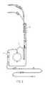
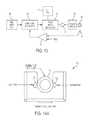
- FIG. 1is a schematic block diagram of a fluid heating apparatus, according to an illustrative embodiment of the present invention.
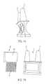
- FIG. 2is a front view of a disposable set, according to an embodiment of the instant invention.
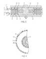
- FIG. 3is a cross-sectional view of an inductive heater employed, shown with a primary inductor, secondary inductors, a conduit, an inlet and an outlet, according to an illustrative embodiment of the present invention.
- FIG. 4is a plan view, with parts broken away, of the heater of FIG. 3 .
- FIG. 5illustrates a single flow path conduit with a fluid separator comprising an inlet nozzle and an outlet nozzle, according to an embodiment of the present invention.
- FIGS. 6A-6Gillustrate a fluid separator, according to an embodiment of the present invention.
- FIGS. 7A and 7Bare optical images of a fluid separator, according to an embodiment of the present invention.
- FIG. 8shows a part of a disposable set with a fluid separator, a conduit and a plurality of secondary inductors, according to an embodiment of the present invention.
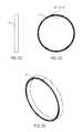
- FIGS. 9A-9Edepict a spiral inductive tube, according to an embodiment of the present invention.
- FIGS. 10A-10Edepict a spiral inductive tube, according to other embodiments of the present invention.
- FIG. 11shows a spiral inductive tube, according to an embodiment of the present invention.
- FIG. 12is a schematic representation of a slack time heating system with an associated disposable set, according to an embodiment of the present invention.
- FIG. 13is a schematic block diagram of circuitry for energizing the inductive heater of FIGS. 3 and 4 .
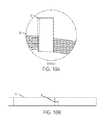
- FIGS. 14A-14Cdemonstrate a sensor for a fluid level in a reservoir, and deformation of an inflow tubing.
- FIGS. 15A-15Cdepict exemplary disposable set with vacuum release valve, according to an embodiment of the present invention.
- administrationtypically refers to the administration of a composition to a subject or system.
- routesthat may, in appropriate circumstances, be utilized for administration to a subject, for example a human.
- administrationmay be ocular, oral, parenteral, topical, etc.
- administrationmay be bronchial (e.g., by bronchial instillation), buccal, dermal (which may be or comprise, for example, one or more of topical to the dermis, intradermal, interdermal, transdermal, etc.), enteral, intra-arterial, intradermal, intragastric, intramedullary, intramuscular, intranasal, intraperitoneal, intrathecal, intravenous, intraventricular, within a specific organ (e. g. intrahepatic), mucosal, nasal, oral, rectal, subcutaneous, sublingual, topical, tracheal (e.g., by intratracheal instillation), vaginal, vitreal, etc.
- bronchiale.g., by bronchial instillation
- buccalwhich may be or comprise, for example, one or more of topical to the dermis, intradermal, interdermal, transdermal, etc.
- enteralintra-arterial, intradermal, intragas
- administrationmay involve dosing that is intermittent (e.g., a plurality of doses separated in time) and/or periodic (e.g., individual doses separated by a common period of time) dosing. In certain embodiments, administration may involve continuous dosing (e.g., perfusion) for at least a selected period of time.
- biocompatiblerefers to materials that do not cause significant harm to living tissue when placed in contact with such tissue, e.g., in vivo. In certain embodiments, materials are “biocompatible” if they are not toxic to cells. In certain embodiments, materials are “biocompatible” if their addition to cells in vitro results in less than or equal to 20% cell death, and/or their administration in vivo does not induce significant inflammation or other such adverse effects.
- composition or method described herein as “comprising” one or more named elements or stepsis open-ended, meaning that the named elements or steps are essential, but other elements or steps may be added within the scope of the composition or method.
- any composition or method described as “comprising” (or which “comprises”) one or more named elements or stepsalso describes the corresponding, more limited composition or method “consisting essentially of” (or which “consists essentially of”) the same named elements or steps, meaning that the composition or method includes the named essential elements or steps and may also include additional elements or steps that do not materially affect the basic and novel characteristic(s) of the composition or method.
- composition or method described herein as “comprising” or “consisting essentially of” one or more named elements or stepsalso describes the corresponding, more limited, and closed-ended composition or method “consisting of” (or “consists of”) the named elements or steps to the exclusion of any other unnamed element or step.
- known or disclosed equivalents of any named essential element or stepmay be substituted for that element or step.
- the term “designed”refers to an agent (i) whose structure is or was selected by the hand of man; (ii) that is produced by a process requiring the hand of man; and/or (iii) that is distinct from natural substances and other known agents.
- low flow raterefers to a non-zero (e.g., no less than 1 ml/min) flow rate less than about 100 ml/min, or less than about 50 ml/min, or less than about 40 ml/min, or less than about 30 ml/min, or less than about 20 ml/min, or less than about 15 ml/min, or less than about 10 ml/min.
- a patientrefers to any organism to which a provided composition is or may be administered, e.g., for experimental, diagnostic, prophylactic, cosmetic, and/or therapeutic purposes. Typical patients include animals (e.g., mammals such as mice, rats, rabbits, non-human primates, and/or humans). In certain embodiments, a patient is a human. In certain embodiments, a patient is suffering from or susceptible to one or more disorders or conditions. In certain embodiments, a patient displays one or more symptoms of a disorder or condition. In certain embodiments, a patient has been diagnosed with one or more disorders or conditions. In certain embodiments, the disorder or condition is or includes cancer, or presence of one or more tumors. In certain embodiments, the patient is receiving or has received certain therapy to diagnose and/or to treat a disease, disorder, or condition.
- animalse.g., mammals such as mice, rats, rabbits, non-human primates, and/or humans.
- a patientis a human.
- a patientis suffering from or susceptible to one or
- the term “substantially”refers to the qualitative condition of exhibiting total or near-total extent or degree of a characteristic or property of interest.
- treatmentrefers to any administration of a therapy that partially or completely alleviates, ameliorates, relives, inhibits, delays onset of, reduces severity of, and/or reduces incidence of one or more symptoms, features, and/or causes of a particular disease, disorder, and/or condition.
- such treatmentmay be of a subject who does not exhibit signs of the relevant disease, disorder and/or condition and/or of a subject who exhibits only early signs of the disease, disorder, and/or condition.
- such treatmentmay be of a subject who exhibits one or more established signs of the relevant disease, disorder and/or condition.
- treatmentmay be of a subject who has been diagnosed as suffering from the relevant disease, disorder, and/or condition. In certain embodiments, treatment may be of a subject known to have one or more susceptibility factors that are statistically correlated with increased risk of development of the relevant disease, disorder, and/or condition.
- compositionsare described as having, including, or comprising specific components, or where methods are described as having, including, or comprising specific steps, it is contemplated that, additionally, there are compositions of the present invention that consist essentially of, or consist of, the recited components, and that there are methods according to the present invention that consist essentially of, or consist of, the recited processing steps.
- the present disclosurerelates to warming of fluid (e.g., blood, blood products, hyperthermia fluid, and more).
- fluide.g., blood, blood products, hyperthermia fluid, and more.
- the present disclosureencompasses system, apparatus and/or methods of warming fluids.
- resistive heatingi.e., Joule heating
- the resistive heatersare smaller than the heaters with the water bath, however, the resistive heaters can encounter overheating the infusate.
- a local temperature of the resistive heaterscan reach up to about 80° C., denaturing proteins in the infusate.
- Some blood warmersutilize inductive or electro-magnetic heating techniques, involving a circular heat exchanger tailored to the shape of the magnetic field. Fluid is introduced into the toroid at a point where the fluid path bifurcates with each half flowing on opposites sides of the toroid, until the two halves rejoin at the fluid output of the toroid.
- the electro-magnetic heaterincludes a primary inductor (coil), generating an alternating magnetic field. A high current density in the secondary inductor converts electric energy into thermal energy, so that the secondary inductor provides heat to a fluid.
- This effective heat exchange system of the Belmont® Rapid Infuserenables fluid (e.g., blood, blood products with temperature of 4 to 37.5° C.) to be heated to a target temperature (e.g., normothermia) in a single pass. Moreover, a user can control heat flux to the fluid precisely, thus, the electro-magnetic heating system prevents overheating. Furthermore, size of the Belmont® Rapid Infuser and the Belmont® Hyperthermia Pump is significantly smaller (e.g., IV-pole mountable) than other commercial fluid heaters.
- Embodiments described hereinaddress a problem that can sometimes arise with toroidal heat exchangers with dual flow paths.
- the pressure drop from the flow paths to the outletmay be insufficient to support flow through both paths, causing flow to occur on a single side of the dual flow path, only.
- the other side of the dual flow paththerefore, encounters stagnant or slow flow.
- the stagnant or slow flow in a toroidal heat exchangermay be a concern, when blood or blood products have either been improperly anticoagulated or have had the anticoagulant compromised (e.g., mixed with lactated Ringer's or other solution containing calcium), clogs may occur.
- the clogged flow pathcan become overheated due to insufficient supply of fluids, which absorb heat from the heat exchangers (e.g., decrease the temperature of the heat exchangers).
- Embodiments of the present disclosureinclude new designs that provide a single flow path without compromising advantages of the existing blood warmers, such that the heat exchanger would not experience stagnant flow that may cause overheating of a local flow path.
- the single flow pathis found to obviate problems that may occur with the dual flow path system due to improper usage (e.g., use of blood or blood products that have not been properly anticoagulated).
- a fluid heating systemcomprises a reservoir of infusate (e.g., blood, plasma or other solution).
- Fluid tubular lines and connectors of an infusion fluid disposable setdirect fluid to reservoirs of the infusion fluid disposable set. Additional tubular fluid lines and connectors of a disposable set direct fluid from reservoirs to and through a heater.
- Infusate drawn from reservoir 11is driven by a pump 13 (e.g., roller pump) through an inductive heater constructed in accordance with the present disclosure. Heated fluid is directed into a patient tubular fluid feed line to a patient's body.
- infusateis brought to a preselected temperature; control of the temperature is affected by feedback circuitry 21 and responds to outlet temperature, e.g., as sensed by a temperature sensor 51 to control the energization of an inductor, which effects the heat generation in the heater 15 .
- This feedback circuitryis described in greater detail below. From the heater 15 , the infusate passes through a separator 23 , which removes all air and then passes to the patient.
- the heater 15involves a conduit or housing 25 , which may be constructed of a suitable plastic material.
- a fluid separator 47provides an inlet 27 and an outlet 29 , which are connected by a ring-like annular chamber 31 , which defines a single flow path with an opening 35 . While the exemplary path is shown as forming a circle, it should be understood that other shapes could also be used, e.g. ovoid.
- a primary inductorcomprising a winding 55 wound on a ferrite bobbin core 56 generates magnetic flux passing through the central opening andis inductively coupled to a plurality of secondary inductors 41 A- 41 J for inducing local currents therein.
- the windingdoes not surround the flow path.
- ferrite magnetic end plates 57 and 58may be employed to extend the flux coverage.
- a fluid heating systemcomprises a reservoir of infusate (e.g., blood, plasma or other solution).
- Fluid tubular lines and connectors of an infusion fluid disposable setdirect fluid to reservoirs of the infusion fluid disposable set. Additional tubular fluid lines and connectors of a disposable set direct fluid from reservoirs to and through a heater.
- Infusate drawn from reservoir 11is driven by a pump 13 (e.g., roller pump) through an inductive heater constructed in accordance with the present disclosure. Heated fluid is directed into a patient tubular fluid feed line to a patient's body.
- infusateis brought to a preselected temperature; control of the temperature is affected by feedback circuitry 21 and responds to outlet temperature, e.g., as sensed by a temperature sensor 51 to control the energization of an inductor, which effects the heat generation in the heater 15 .
- This feedback circuitryis described in greater detail below. From the heater 15 , the infusate passes through a separator 23 , which removes all air and then passes to the patient.
- the heater 15involves a conduit or housing 25 , which may be constructed of a suitable plastic material.
- a fluid separator 47provides an inlet 27 and an outlet 29 , which are connected by a ring-like annular chamber 31 , which defines a single flow path with an opening 35 . While the exemplary path is shown as forming a circle, it should be understood that other shapes could also be used, e.g. ovoid.
- a primary inductorcomprising a winding 55 wound on a ferrite bobbin core 56 generates magnetic flux passing through the central opening and is inductively coupled to a plurality of secondary inductors 41 A- 41 J for inducing local currents therein.
- the windingdoes not surround the flow path.
- ferrite magnetic end plates 57 and 58may be employed to extend the flux coverage.
- the heat exchangercomprises thin or ribbon-like secondary inductors 41 A- 41 J) contained in a chamber 31 .
- the secondary inductorshave a circular ring-like shape. In alternative embodiments, other shapes (e.g., beads) can be used.
- the secondary inductorsextend generally parallel to each other in a spaced relationship (spaced apart) with each secondary inductor passing through the flow path so as to heat the fluid. As will be apparent, fluid flowing from the inlet 27 to outlet 29 will pass through the spaces between the secondary inductors 41 A- 41 J and will be in intimate thermal contact therewith.
- the chamber 31is circular and the secondary inductors 41 A- 41 J are correspondingly formed as flat rings. This shape simplifies obtaining symmetry and uniform heating. In other embodiments, other shapes are used. Spacing between adjacent secondary inductors 41 A- 41 J is maintained by spacers 43 .
- the heat transfer coefficientis a function of the key parameters, for example, conductivity of the solid (e.g., the secondary inductors), gaps between the secondary inductors, etc.
- Total heat transfer from the solid surface to the fluidcan be calculated by multiplying total surface area to heat flux. Therefore, when one changes fluid to be heated and/or operating conditions, it may be desirable to increase or decrease gaps between the secondary inductors, increase or decrease the number of secondary conductors, change the total surface area of secondary inductors, and/or change materials used in the construction of the secondary inductors. For example, in order to accommodate a higher heating capacity (e.g., higher flow rate), the number and/or the total surface area of the secondary conductors may be increased.
- the secondary inductorsis constructed, for example, of stainless steel.
- Other conductive materialssuch as conductive plastics might also be used.
- one or more conductive materialsare selected from the group consisting of stainless steel, carbon (graphene), silver, copper, gold, aluminum, tungsten, zinc, nickel, lithium, iron, platinum, tin, carbon steel, lead, titanium, grain oriented electrical steel, manganin, constantan, mercury, nichrome, carbon (graphite) and combinations thereof.
- a conduit/chamber of the present disclosurehas at least 1, 2, 4, 6, 8, 10, 12, 14, 16, 18 or 20 secondary inductors.
- each gap between secondary inductorshas a distance of about 0.001′′ to about 0.1′′, about 0.001′′ to about 0.1′′, about 0.001′′ to about 0.1′′, or about 0.02′′ to about 0.03′′.
- total surface area of secondary inductorsis about 1 to about 1000 in 2 , about 1 to about 500 in 2 , about 1 to about 250 in 2 , about 10 to about 1000 in 2 , about 10 to about 500 in 2 , or about 10 to about 250 in 2 .
- a fluid separatoris incorporated into a single flow path heating system.
- the fluid separatormay enable a single flow path with minimal modification of the existing system (e.g., same the primary inductor, tubing, etc.).
- An exemplary fluid separatoris depicted in FIGS. 6A-6G, 7A, 7B and 8 .
- the fluid separatorcomprises an inlet nozzle and an outlet nozzle.
- the inlet nozzle 27directs unheated (e.g., cold) fluid to the single flow path, while the outlet nozzle 29 receives heated fluid from the single flow path.
- the inlet and outlet nozzleare substantially parallel to each other to allow flow through the outlet nozzle in an opposite direction to flow through the inlet nozzle.
- the fluid separatorhas a housing.
- the housingprovides an inlet chamber and an outlet chamber in the fluid separator.
- the inlet (e.g., unheated) fluidfirst enters into the inlet chamber, and then moves into the single fluid path.
- the outlet (e.g., heated) fluidexits from the single fluid path, then passes through the outlet chamber.
- Temperatures of the inlet fluid and outlet fluidcan be measured at exterior walls of the inlet chamber and the outlet chamber, respectively.
- a portion of the housingis sufficiently thermally-conductive, so that the temperature of the fluid (e.g., inlet unheated fluid, outlet heated fluid) is substantially identical to the temperature of the housing (e.g., outside of the inlet chamber, the outlet chamber) in contact with the fluid.
- the housingcomprise a notch that can secure a divider.
- the housinghas two convex walls at the inlet chambers and the outlet chambers, from the perspective of each of the inlet chamber and the outlet chamber as shown in FIGS. 6E and 6G .
- Temperature probesmay measure inlet and outlet temperatures at the convex walls.
- a fluid separatorcomprises a divider separating the unheated fluid in the inlet chamber and the heated fluid in the outlet chamber.
- the inlet nozzle 27 and the outlet nozzle 29are connected to different sections of the fluid separator, so that the divider effectively separates the unheated fluid and the heated fluid.
- the divider 48may have a solid upper portion 48 A to satisfactorily separate the inlet chamber from the outlet chamber when the divider is secured in the fluid separator.
- the divider 48may also have a lower portion comprising a plurality of elongations 49 to accommodate a plurality of secondary inductors.
- each elongation 49may block each gap between the ring shaped secondary inductors 41 A- 41 P, so that the divider prevents mixing of the unheated fluid and the heated fluid between the secondary inductors.
- each thickness of the elongations 49are substantially identical to each gap between the secondary inductors.
- the width of the notch and the thickness of the dividerare substantially identical, so that the notch can secure the divider in the fluid separator.
- the cross section of the inlet nozzle 27 A, where it is connected to the inlet chamberis semi-circular as shown in FIG. 6C .
- the cross section of the outlet nozzle 29 A, where it is connected to the outlet chambermay be semi-circular.
- the semi-circular cross-sections of the inlet and the outletare located on opposite sides of the fluid divider, so that the divider can separate the inlet and the outlet when the divider is positioned therebetween.
- the fluid separatoris connected to the peripheral area of the conduit, as shown in FIG. 8 , so that the inlet nozzle and the outlet nozzle do not disturb alternating magnetic fields created by the primary inductor.
- seams between the divider and the housingare sealed. In certain embodiments, seams between the elongations of the divider and the secondary inductors may be sealed. Adhesive may be applied at seams and cured with ultraviolet light.
- a fluid separator of the present disclosureis constructed of insulating materials, for example, polymers and/or plastic so that the separator does not disturb the magnetic field in any instance.
- a spiral inductive tubeprovides a single flow path (e.g., instead of a fluid separator, a conduit, and secondary inductors). Exemplary spiral inductive tubes are depicted in FIGS. 9A-9E and 10A-10E .
- a tubee.g., conductive tube
- the spiral tubecomprises one or more circular loops.
- the spiral tubemay comprise one or two extended tails, which can be connected to an inlet and/or outlet.
- the spiral tubemay comprise a window for measuring temperature of the fluid flowing.
- a primary inductormay be inserted into a central opening of the spiral inductive tube, inductively coupling to the spiral inductive tube for generating local currents therein.
- An unheated fluidenters and flows within the spiral inductive tube, contacting the inner walls of the spiral inductive tube. Heat generated within the inductive walls of the spiral inductive tube (e.g., due to the alternating magnetic fields from the primary inductor) is transferred to the fluid in the spiral inductive tube.
- the spiral inductive tubecomprises one or more conductive wires (e.g., copper) that electrically connect loops.
- the conductive wiresfurther provide electrical shorts within the spiral inductive tube.
- the spiral inductive tubecomprises an insulating housing (e.g., polymer, plastic).
- the spiral inductive tubemay be desirable to modify certain key parameters of the spiral inductive tube. For example, it is desirable to increase or decrease inner and/or outer diameters of the spiral inductive tube, increase or decrease the number of windings, change the total surface area of the spiral inductive tube, and/or change materials used in the construction of the spiral inductive tube. For example, in order to accommodate a higher heating capacity, the total surface area and/or winding of the secondary conductors may be increased.
- a spiral inductive tubeis constructed of one or more conductive materials selected from the group consisting of stainless steel, carbon (graphene), silver, copper, gold, aluminum, tungsten, zinc, nickel, lithium, iron, platinum, tin, carbon steel, lead, titanium, grain oriented electrical steel, manganin, constantan, mercury, nichrome, carbon (graphite) and combinations thereof.
- a spiral inductive tubehas a total interior surface area of about 1 in 2 to about 1000 in 2 , about 5 in 2 to about 1000 in 2 , about 10 in 2 to about 1000 in 2 , about 1 in 2 to about 500 in 2 , about 1 in 2 to about 100 in 2 , or about 1 in 2 to about 50 in 2 .
- an inner diameter of a spiral inductive tuberanges from about 1/32′′ to about 1′′, from about 1/16′′ to about 1′′, from about 1/32′′ to about 1 ⁇ 2′′, from about 1/32′′ to about 1 ⁇ 4′′, or from about 1/16′′ to about 1 ⁇ 4′′.
- a spiral inductive tubewinds about 1 to about 20 times, about 1 to about 10 times, or about 1 to about 5 times.
- the energy inductively coupled to the secondary inductors 41 A- 41 J or the spiral inductive tubeis preferably controlled to maintain a preselected temperature at the outlet of the heater.
- Circuitry suitable for this purposeis illustrated in FIG. 13 .
- the sensor 51provides an output signal corresponding to the temperature at the outlet of the heater. This temperature signal is compared with a reference voltage representing a desired temperature, e.g. 42° C., by an error amplifier designated generally by reference character 63 .
- the error signal obtained from the error amplifier 63is applied to a modulator 65 which modulates an amplitude cycle of a low frequency signal obtained from a sine wave oscillator 66 .
- the pulse width of this amplitude modulated signalis in turn varied, as indicated at 67 using a high frequency signal obtained from an oscillator 71 .
- This signalis in turn applied through suitable driver circuitry 77 to a bridge type power output circuit 79 , which provides alternating current energization of the inductor winding 55 .
- an exemplary system of the present disclosurereceives electric power by an Alternating Current (AC) wall outlet.
- the systemis operated from battery power.
- ACAlternating Current
- the systemoffers adjustability of flow rate of a fluid from 1 ml/min to 2000 ml/min, or from 10 ml/min to 2000 ml/min.
- the systemobviates clogging problems that may result from low flow in dual flow path systems.
- the embodiments of the single flow path system described hereinprovide for advantageous operation at low flow rates, e.g., non-zero flow rates of less than about 100 ml/min, or less than about 50 ml/min, or less than about 40 ml/min, or less than about 30 ml/min, or less than about 20 ml/min, or less than about 15 ml/min, or less than about 10 ml/min.
- an exemplary system of the present disclosurecomprises a bubble trap that separates air from fluid by gravitational force.
- the bubble trapmay have a chamber. Air introduced by a pump into a fluid may move to the top of the chamber, while the heated fluid exits from the bottom of the chamber.
- a conduitis included as part of a disposable set.
- secondary inductorsare included as part of a disposable set.
- a fluid separatoris included as part of a disposable set.
- a spiral inductive tubeis included as part of a disposable set.
- a bubble trapis included as part of a disposable set.
- a housingis included as part of a disposable set.
- a disposable setis for a single use. A disposable set is constructed of materials that can be sterilized and made pyrogen free by conventional methods and so that single uses thereof are economically feasible.
- components that the biological fluide.g., blood
- Drawbacks of this approachinclude the necessity to later transfer energy to the infusate before/during infusion with the limited heat transfer rate of the system (e.g., due to a limited surface area between water/oil and infusate) and the potential contamination of the infusate by the fluid bath.
- the present disclosureis directed to a slack-time heating system that utilizes excess heating capacity of fluid heaters to pre-warm fluid in a reservoir.
- the present disclosuredescribes a heating system to store heat energy within a reservoir (e.g., in infusate) during off peak periods (e.g., when low flow is required) for later use (e.g., when high flow is required).
- FIG. 12depicts an exemplary slack-time heating system.
- the systemcomprises a large volume reservoir 81 connected to a pump tubing 105 threaded through a roller pump head further connected to a heat exchanger 87 .
- the fluid pathcontinues to a pressure chamber 89 and then directs one path to a patient via a patient line 103 or back to the reservoir 81 via a recirculation line 97 .
- a slack-time heating systemcomprises a diversion valve 93 that controls the ratio between a flow in a patient line and a flow in a recirculation line.
- the diversion valveWhen the diversion valve is in a recirculation position (e.g., the patient line is obstructed, while the recirculation line is opened), the pump 107 will cause fluid in a bubble trap to flow back to the reservoir (e.g., exit from the top).
- reservoirs of the present disclosuremix unheated fluid and heated fluid.
- the ratio of a flow in a patient line to a flow in a recirculation lineis between 100:1 and 1:100.
- the slack time heating systemutilizes a single flow path as described in the present disclosure.
- a fluid heating systemhas a sensor (e.g., fluid out sensor) 119 connected to an inflow tubing 121 (e.g., from an infusate reservoir to fluid heaters) to detect if an infusate reservoir is empty.
- the sensorcomprises a transmitter 123 and a receiver 125 , and measures velocity of ultrasound (e.g., ultrasound travels faster through fluids than air) as shown in FIG. 14A .
- the inflow tubing 121is located between the transmitter 123 and the receiver 125 . When the fluid level in the infusate reservoir is low (or zero), the pressure in the infusate reservoir and the inflow tubing is lower than the atmospheric pressure.
- the non-rigid inlet tubing 121deforms to minimize the pressure difference.
- the cross-section area of the inlet tubingreduces, or the cross-section of the inflow tubing becomes elliptic, as shown in FIGS. 14B and 14C .
- the sensormeasures this deformation of the inflow tubing.
- the direction of deformationaffects detectability by the sensor.
- a major axis of the elliptic cross-sectioncan be perpendicular to a line between the transmitter and the receiver as shown in FIG. 14C , or parallel to that line as shown in FIG. 14B . If the major axis of the elliptic cross-section is not parallel (e.g., perpendicular) to the line between the transmitter and the receiver, the sensor can measure the deformation properly as the ultrasound travels in air more than before the deformation. However, if the major axis of the elliptic cross-section is parallel to a line between the transmitter and the receiver, the sensor cannot detect the deformation because of lack of air in the ultrasound beam path.
- the present disclosureis directed to a fluid heating system that includes a vacuum release valve to prevent the undesired orientation of the deformed inflow tubing.
- the vacuum release valvesupply air to the tubing to reduce pressure difference between the inflow tubing and the surroundings, preventing the deformation of the inflow tubing.
- FIGS. 15A-15Cdepict exemplary disposable sets with vacuum release valves.
- the vacuum release valve 127 Ais connected on the bottom of the reservoir ( FIG. 15A ).
- the inflow tubing and the vacuum release valvemay be parallel to each other.
- the vacuum release valve 127 Cis connected on the bottom of the reservoir ( FIG. 15C ).
- the vacuum release valveis indirectly connected to the reservoir.
- the reservoirmay comprise a tubing attached to the top of the reservoir ( FIG. 15B ).
- the vacuum release valvemay be connected to the reservoir through the tubing.
- the vacuum release valvemay comprise a housing and a regulator.
- the vacuum release valvemay operate automatically (e.g., without an operator).
- the vacuum release valveis normally closed (e.g., the vacuum release valve does not allow air into the inflow tubing, e.g., the regulator presses against a portion of the housing, thereby blocking air passage).
- a pre-determined valuee.g., 0.5, 1, 2, 3, 4, 5, 6, 7, 8, 9 or 10 psi
- the vacuum release valveopens (e.g., the valve allows air to flow into the system).
- the pre-determined valuemay be manipulated by varying an external force applied to the regulator. For example, if the pressure difference between the system (e.g., the reservoir, inflow tubing) and the atmosphere exceeds the applied force per area, the valve opens.
- the forcemay be applied mechanically (e.g., spring, diaphragm).
- the vacuum release valvesupplies air to the disposable set when the pressure of the disposable set is about 0.5, 1, 2, 3, 4, 5, 6, 7, 8, 9, or 10 psi lower than atmospheric pressure.
- the vacuum release valvecomprises a filter, and/or a sanitation unit to provide sterile air to the system.
- a vacuum release valveis included as part of a disposable set.
- the present exampledescribes, among other things, an exemplary operation of single flow path induction heater with an exemplary spiral inductive tube.
- the present exampledescribes, among other things, exemplary operations of a rapid heating system with exemplary vacuum release valves.
- Disposable setse.g., The Belmont® 3-Spike Disposable Set
- various vacuum release valvesas shown in FIGS. 15A-15C were tested with the Belmont Rapid Infuser.
- a vacuum release valvewas connected to the 4.4 L reservoir ( FIG. 15A ), a y-connection at the intersection of tubing ( FIG. 15B ), or onto the filter assembly ( FIG. 15C ).
- the modified disposable sets and the unmodified setwere then tested. Testing mediums were water, sodium chloride and water at 35.7 grams per 100 mL, and a 50/50 mix of water and glycerin by volume. Each modified disposable set was tested at a wide range of flow rates.
- the vacuum release valve of the modified setsallowed air to be drawn into the set, and did not experience clamping off. Once the reservoir was sufficiently emptied, air would be drawn into the fluid path causing the fluid out detector to register and the machine to turn off properly. The valve worked successfully with all testing mediums and at any flow rate. The addition of the vacuum release valve prevented the improper deformation of tubing.
Landscapes
- Health & Medical Sciences (AREA)
- Life Sciences & Earth Sciences (AREA)
- Public Health (AREA)
- Engineering & Computer Science (AREA)
- Anesthesiology (AREA)
- Biomedical Technology (AREA)
- Heart & Thoracic Surgery (AREA)
- Vascular Medicine (AREA)
- Animal Behavior & Ethology (AREA)
- Hematology (AREA)
- General Health & Medical Sciences (AREA)
- Veterinary Medicine (AREA)
- Emergency Medicine (AREA)
- Physics & Mathematics (AREA)
- Electromagnetism (AREA)
- Infusion, Injection, And Reservoir Apparatuses (AREA)
Abstract
Description
q=h·ΔT
wherein q is heat flux (W/m2), h is a heat transfer coefficient (W/m2·K), and ΔT is the difference in temperature between the solid surface and surrounding fluid area (K). The heat transfer coefficient is a function of the key parameters, for example, conductivity of the solid (e.g., the secondary inductors), gaps between the secondary inductors, etc. Total heat transfer from the solid surface to the fluid can be calculated by multiplying total surface area to heat flux. Therefore, when one changes fluid to be heated and/or operating conditions, it may be desirable to increase or decrease gaps between the secondary inductors, increase or decrease the number of secondary conductors, change the total surface area of secondary inductors, and/or change materials used in the construction of the secondary inductors. For example, in order to accommodate a higher heating capacity (e.g., higher flow rate), the number and/or the total surface area of the secondary conductors may be increased.
Claims (21)
Priority Applications (4)
| Application Number | Priority Date | Filing Date | Title |
|---|---|---|---|
| US15/364,532US10507292B2 (en) | 2016-11-30 | 2016-11-30 | Rapid infuser with vacuum release valve |
| US16/464,115US11872382B2 (en) | 2016-11-30 | 2017-11-29 | Rapid infuser with advantageous flow path for blood and fluid warming, and associated components, systems, and methods |
| PCT/US2017/063612WO2018102354A1 (en) | 2016-11-30 | 2017-11-29 | Rapid infuser with advantageous flow path for blood and fluid warming, and associated components, systems, and methods |
| EP17817513.9AEP3548124A1 (en) | 2016-11-30 | 2017-11-29 | Rapid infuser with advantageous flow path for blood and fluid warming, and associated components, systems, and methods |
Applications Claiming Priority (1)
| Application Number | Priority Date | Filing Date | Title |
|---|---|---|---|
| US15/364,532US10507292B2 (en) | 2016-11-30 | 2016-11-30 | Rapid infuser with vacuum release valve |
Related Parent Applications (1)
| Application Number | Title | Priority Date | Filing Date |
|---|---|---|---|
| US15/364,515ContinuationUS10137257B2 (en) | 2016-11-30 | 2016-11-30 | Slack-time heating system for blood and fluid warming |
Related Child Applications (2)
| Application Number | Title | Priority Date | Filing Date |
|---|---|---|---|
| US15/364,499ContinuationUS10485936B2 (en) | 2016-11-30 | 2016-11-30 | Rapid infuser with advantageous flow path for blood and fluid warming |
| US16/464,115ContinuationUS11872382B2 (en) | 2016-11-30 | 2017-11-29 | Rapid infuser with advantageous flow path for blood and fluid warming, and associated components, systems, and methods |
Publications (2)
| Publication Number | Publication Date |
|---|---|
| US20180147369A1 US20180147369A1 (en) | 2018-05-31 |
| US10507292B2true US10507292B2 (en) | 2019-12-17 |
Family
ID=62193452
Family Applications (1)
| Application Number | Title | Priority Date | Filing Date |
|---|---|---|---|
| US15/364,532Active2038-01-16US10507292B2 (en) | 2016-11-30 | 2016-11-30 | Rapid infuser with vacuum release valve |
Country Status (1)
| Country | Link |
|---|---|
| US (1) | US10507292B2 (en) |
Families Citing this family (5)
| Publication number | Priority date | Publication date | Assignee | Title |
|---|---|---|---|---|
| US11000407B2 (en) | 2007-08-07 | 2021-05-11 | Belmont Instrument, Llc | Hyperthermia, system, method, and components |
| US10137257B2 (en) | 2016-11-30 | 2018-11-27 | Belmont Instrument, Llc | Slack-time heating system for blood and fluid warming |
| US10485936B2 (en) | 2016-11-30 | 2019-11-26 | Belmont Instrument, Llc | Rapid infuser with advantageous flow path for blood and fluid warming |
| CN114302753A (en) | 2019-08-16 | 2022-04-08 | 贝尔蒙特仪器有限公司 | Fluid Temperature Control System |
| CN116660440B (en)* | 2023-07-31 | 2023-11-10 | 广州禾信仪器股份有限公司 | Liquid separation collector control method and device and liquid separation collector |
Citations (115)
| Publication number | Priority date | Publication date | Assignee | Title |
|---|---|---|---|---|
| US1656518A (en) | 1926-08-23 | 1928-01-17 | William J Hammers | Electric water heater |
| US2494716A (en) | 1945-11-08 | 1950-01-17 | Induction Heating Corp | Method and apparatus for treating materials dielectrically |
| US2550584A (en) | 1949-02-03 | 1951-04-24 | Mittelmann Eugene | Milk pasteurization method and apparatus |
| US2886771A (en) | 1955-06-14 | 1959-05-12 | George A Rubissow | Fluid-testing device |
| US3046378A (en) | 1960-04-25 | 1962-07-24 | Lindberg Eng Co | Fluid heater |
| US3315681A (en) | 1964-08-17 | 1967-04-25 | Heinz F Poppendiek | Means and techniques useful for changing temperature of fluids, particularly blood |
| US3388230A (en) | 1964-02-28 | 1968-06-11 | Westinghouse Electric Corp | Inductionally heated vapor generators and other fluid systems |
| US3399536A (en) | 1966-02-02 | 1968-09-03 | Siemens Ag | Device for varying the blood temperature |
| US3443060A (en) | 1967-02-09 | 1969-05-06 | Gorman Rupp Co | Thermostatically controlled electric blood heating apparatus |
| US3475590A (en) | 1966-10-25 | 1969-10-28 | Thermolyne Corp | Thermostatically controlled electrically heated clinical blood warmer |
| US3482575A (en) | 1967-02-16 | 1969-12-09 | Single Cell Research Foundatio | Method for the extracorporeal oxygenation of blood |
| US3485245A (en) | 1967-06-21 | 1969-12-23 | Ibm | Portable fluid heater |
| US3518393A (en) | 1967-11-21 | 1970-06-30 | South African Inventions | Bloodwarmers |
| US3590215A (en) | 1969-03-27 | 1971-06-29 | Thermolyne Corp | Clinical fluid warmer |
| US3614385A (en) | 1968-07-03 | 1971-10-19 | Bevan Graham Horstmann | Blood-heating apparatus |
| US3640283A (en) | 1970-03-02 | 1972-02-08 | Baxter Laboratories Inc | Disposable blood-warming container |
| US3641302A (en) | 1970-03-18 | 1972-02-08 | Ralph G Sargeant | Apparatus for treating liquids with high-frequency electrical energy |
| US3812315A (en) | 1973-02-27 | 1974-05-21 | N Martin | Micro-wave heater |
| US3816687A (en) | 1972-02-03 | 1974-06-11 | Esser Kg Klaus | Electrically heated water outlets |
| US3834372A (en) | 1973-01-12 | 1974-09-10 | S Turney | Disposable manifold with atmospheric vent |
| US3853479A (en) | 1972-06-23 | 1974-12-10 | Sherwood Medical Ind Inc | Blood oxygenating device with heat exchanger |
| US4032740A (en) | 1975-04-07 | 1977-06-28 | Illinois Tool Works Inc. | Two-level temperature control for induction heating |
| US4038519A (en) | 1973-11-15 | 1977-07-26 | Rhone-Poulenc S.A. | Electrically heated flexible tube having temperature measuring probe |
| US4061141A (en) | 1969-03-21 | 1977-12-06 | Viktor Holger Hyden | Apparatus and method for selectively separating amino acids and defined proteins in blood |
| US4089176A (en) | 1976-01-20 | 1978-05-16 | The Garrett Corporation | Heat storage method and apparatus |
| US4108146A (en) | 1977-05-16 | 1978-08-22 | Theodore Alan Golden | Bendable thermal pack unit |
| US4167663A (en) | 1977-01-24 | 1979-09-11 | Baxter Travenol Laboratories, Inc. | Blood warming apparatus |
| US4191182A (en) | 1977-09-23 | 1980-03-04 | Hemotherapy Inc. | Method and apparatus for continuous plasmaphersis |
| US4293762A (en) | 1978-02-16 | 1981-10-06 | Genshirou Ogawa | Temperature-controlled electric heating device for heating instillation or transfusion liquids |
| US4309592A (en) | 1977-10-07 | 1982-01-05 | Guy Le Boeuf | Electric heating device for heating sterilized fluids, such as blood |
| US4314143A (en) | 1979-06-29 | 1982-02-02 | Baxter Travenol Laboratories, Inc. | Blood warming apparatus with digital display and monitoring circuit |
| US4321918A (en) | 1979-10-23 | 1982-03-30 | Clark Ii William T | Process for suppressing immunity to transplants |
| US4322275A (en) | 1980-01-10 | 1982-03-30 | Ionics Incorporated | Fractionation of protein mixtures |
| US4341936A (en) | 1979-12-17 | 1982-07-27 | Virgin George C | Electromagnetic induction energy converter |
| US4356383A (en) | 1978-11-22 | 1982-10-26 | Gambro Ab | Thermostatically controlled electric fluid heating apparatus |
| US4381004A (en) | 1981-01-15 | 1983-04-26 | Biomedics, Inc. | Extracorporeal system for treatment of infectious and parasitic diseases |
| US4384578A (en) | 1981-04-16 | 1983-05-24 | The United States Of America As Represented By The Administrator Of The National Aeronautics And Space Administration | Bio-medical flow sensor |
| US4464563A (en) | 1981-08-28 | 1984-08-07 | Jewett Warren R | Intravenous fluid warmer |
| US4479798A (en) | 1977-05-31 | 1984-10-30 | Research Against Cancer, Inc. | Subcutaneous implant useful in effecting hyperthermic treatment |
| US4511777A (en) | 1984-07-19 | 1985-04-16 | Frank Gerard | Permanent magnet thermal energy system |
| US4532414A (en) | 1980-05-12 | 1985-07-30 | Data Chem., Inc. | Controlled temperature blood warming apparatus |
| US4540401A (en) | 1983-02-22 | 1985-09-10 | Applied Immune Sciences, Inc. | In vivo therapeutic apheresis using lipid vesicles |
| US4560849A (en) | 1984-06-13 | 1985-12-24 | The United States Of America As Represented By The United States Department Of Energy | Feedback regulated induction heater for a flowing fluid |
| US4563170A (en) | 1982-07-30 | 1986-01-07 | Karl Aigner | Device for in vivo purification of blood |
| US4574876A (en) | 1981-05-11 | 1986-03-11 | Extracorporeal Medical Specialties, Inc. | Container with tapered walls for heating or cooling fluids |
| US4576143A (en) | 1984-10-05 | 1986-03-18 | Clark Iii William T | Method of immune modification by means of extracorporeal irradiation of the blood |
| US4602140A (en) | 1984-11-01 | 1986-07-22 | Mangels Industrial S.A. | Induction fluid heater |
| US4638135A (en) | 1984-01-20 | 1987-01-20 | Kabushiki Kaisha Toshiba | Induction heat cooking apparatus |
| US4678460A (en) | 1985-02-11 | 1987-07-07 | Rosner Mark S | Portable rapid massive parenteral fluid warming and infusion apparatus |
| US4680445A (en) | 1984-09-06 | 1987-07-14 | Genshiro Ogawa | Electronically-controlled heating device for infusion liquids |
| US4692138A (en) | 1984-10-29 | 1987-09-08 | Mcneilab, Inc. | Pump block for interfacing irradiation chamber to photoactivation patient treatment system |
| US4707587A (en) | 1986-01-27 | 1987-11-17 | Greenblatt Gordon M | Blood warming method and apparatus using gaseous heat exchange medium |
| US4731072A (en) | 1981-05-11 | 1988-03-15 | Mcneilab, Inc. | Apparatus for heating or cooling fluids |
| US4759749A (en) | 1986-05-27 | 1988-07-26 | Level 1 Technologies, Inc. | Heater for physiological fluids |
| US4782212A (en) | 1986-11-17 | 1988-11-01 | Bakke Allan P | Electric blood warmer utilizing a metallic ribbon-flow cartridge |
| US4801777A (en) | 1987-09-03 | 1989-01-31 | Vanderbilt University | Blood rewarming method and apparatus |
| US4844074A (en) | 1986-04-11 | 1989-07-04 | Rolitron Muszaki-Fejleszto Kisszovetkezet | Method and apparatus for introducing a fluid into a human or animal organism as well as method and heating device for temperature control |
| US4847470A (en) | 1987-12-14 | 1989-07-11 | Bakke Allan P | Electric blood warmer utilizing metallic ribbon flow cartridge and low thermal mass heating units |
| US4855552A (en) | 1986-10-01 | 1989-08-08 | Hydro-Quebec | Fluid heating device incorporating transformer secondary winding having a single electrical turn and cooling means optimized for heat transfer |
| US4874359A (en) | 1987-12-14 | 1989-10-17 | White Frederick R | Power infuser |
| US4878537A (en) | 1986-05-27 | 1989-11-07 | Level 1 Technologies | Heat exchanger for physiological fluids |
| US4906816A (en) | 1987-05-22 | 1990-03-06 | Medistad Holland B.V. | Blood heating apparatus for heating plastic blood supply pouches |
| US4907145A (en) | 1989-05-11 | 1990-03-06 | Belmont Instrument Corporation | Sine wave inverter |
| US4908014A (en) | 1986-03-10 | 1990-03-13 | Kroyer K K K | Extracorporal thermo-therapy device and method for curing diseases |
| US4938279A (en) | 1988-02-05 | 1990-07-03 | Hughes Aircraft Company | Flexible membrane heat sink |
| US4962761A (en) | 1987-02-24 | 1990-10-16 | Golden Theodore A | Thermal bandage |
| US5003145A (en) | 1988-12-15 | 1991-03-26 | E. Blum Gmbh & Co. | Inductively operated heating apparatus for plastic materials |
| US5062775A (en) | 1989-09-29 | 1991-11-05 | Rocky Mountain Research, Inc. | Roller pump in an extra corporeal support system |
| US5108372A (en) | 1990-12-12 | 1992-04-28 | Houston Advanced Research Center | Intravenous fluid temperature regulation method and apparatus |
| US5125069A (en) | 1989-12-22 | 1992-06-23 | Netherlands Health Sciences | Blood warmer |
| WO1992017040A1 (en) | 1991-03-15 | 1992-10-01 | In-Touch Products Co. | Parenteral fluid warmer cassette, system and methods |
| US5188604A (en) | 1989-09-29 | 1993-02-23 | Rocky Mountain Research, Inc. | Extra corporeal support system |
| US5250032A (en) | 1991-12-13 | 1993-10-05 | Spectralogic, Inc. | Heater for in vivo blood infusion |
| US5254094A (en) | 1989-07-17 | 1993-10-19 | Starkey David L | Physiological fluid warmer |
| US5319170A (en) | 1992-10-20 | 1994-06-07 | Belmont Instrument Corporation | Induction fluid heater utilizing a shorted turn linking parallel flow paths |
| DE4241830A1 (en) | 1992-12-11 | 1994-06-16 | Litterst Werner Alfons | Heating device for infusion solution - has heating element incorporated in heat transfer element with reception channel for infusion solution line |
| US5344568A (en) | 1991-10-11 | 1994-09-06 | Children's Hospital Medical Center | Hemofiltration system and method |
| US5354277A (en) | 1992-09-04 | 1994-10-11 | Biocontrol Technology, Inc. | Specialized perfusion protocol for whole-body hyperthermia |
| US5381510A (en) | 1991-03-15 | 1995-01-10 | In-Touch Products Co. | In-line fluid heating apparatus with gradation of heat energy from inlet to outlet |
| US5408577A (en) | 1992-03-16 | 1995-04-18 | Sonne Medical | Method and heater apparatus with protective fuse for medical applications |
| US5420962A (en) | 1993-10-25 | 1995-05-30 | Bakke; Allan P. | Convection blood warming system with disposable flattened tube envelope having vent incorporating a hydrophobic filter |
| US5476444A (en) | 1992-09-04 | 1995-12-19 | Idt, Inc. | Specialized perfusion protocol for whole-body hyperthermia |
| US5571153A (en) | 1991-09-20 | 1996-11-05 | Wallst+E,Acu E+Ee N; Hans I. | Device for hyperthermia treatment |
| WO1996040331A1 (en) | 1995-06-07 | 1996-12-19 | Urosurge, Inc. | Fluid warming system for heating a fluid prior to delivery of the fluid to a patient |
| US5690815A (en) | 1992-07-13 | 1997-11-25 | Pall Corporation | Automated system for processing biological fluid |
| US5702358A (en) | 1995-02-23 | 1997-12-30 | Sorin Biomedical Inc. | Cardioplegia delivery apparatus and method of use |
| US5846224A (en) | 1996-10-01 | 1998-12-08 | Baxter International Inc. | Container for use with blood warming apparatus |
| US5913814A (en) | 1997-08-26 | 1999-06-22 | Belmont Instrument Corporation | Method and apparatus for deflation of an intra-aortic balloon |
| WO2000002608A1 (en) | 1998-07-10 | 2000-01-20 | Belmont Instrument Corporation | Wearable intravenous fluid heater |
| US6045648A (en) | 1993-08-06 | 2000-04-04 | Minnesta Mining And Manufacturing Company | Thermoset adhesive having susceptor particles therein |
| US6117076A (en) | 1998-09-21 | 2000-09-12 | Belmont Instruments Corporation | Patient monitoring system and method |
| US20010039441A1 (en) | 1998-01-23 | 2001-11-08 | Viacirq, Inc. | Apparatuses and processes for whole-body hyperthermia |
| US6579496B1 (en) | 1999-05-25 | 2003-06-17 | Viacirq, Inc. | Apparatus for implementing hyperthermia |
| US20030139788A1 (en) | 2002-01-18 | 2003-07-24 | Eggers Philip E. | System method and apparatus for localized heating of tissue |
| US6827898B1 (en) | 1999-05-25 | 2004-12-07 | Viacirq, Inc. | Hyperthermia method and apparatus |
| US20050222653A1 (en) | 1998-04-21 | 2005-10-06 | Alsius Corporation | Indwelling heat exchange catheter and method of using same |
| US20060089586A1 (en) | 2004-10-22 | 2006-04-27 | Kaus Stanley B | Convertible extracorporeal blood perfusion systems |
| US20070051409A1 (en) | 2005-09-02 | 2007-03-08 | Belmont Instrument Corporation | Pressure responsive fluid flow control valves |
| US20090012655A1 (en) | 2007-07-05 | 2009-01-08 | Baxter International Inc. | Dialysis fluid heating algorithms |
| US20090012450A1 (en) | 2007-07-05 | 2009-01-08 | Baxter International Inc. | Extended use dialysis system |
| US20090043256A1 (en)* | 2007-08-07 | 2009-02-12 | John Landy | Hyperthermia, system, method and components |
| US7842002B2 (en) | 2002-11-12 | 2010-11-30 | Mantle Ross E | Device for the extravascular recirculation of liquid in body cavities |
| US20110196302A1 (en) | 2010-02-06 | 2011-08-11 | Gildersleeve Michael R | Cannula apparatus |
| US8100881B2 (en) | 2009-08-04 | 2012-01-24 | Cook Medical Technologies Llc | Flexible medical device for clot removal from small vessels |
| US20120302995A1 (en) | 2010-02-02 | 2012-11-29 | Pramote Hochareon | Localized Therapy Delivery and Local Organ Protection |
| US8387963B2 (en) | 2009-03-25 | 2013-03-05 | Belmont Instrument Corporation | Clamp |
| US8439960B2 (en) | 2007-07-09 | 2013-05-14 | Velomedix, Inc. | Hypothermia devices and methods |
| US8480648B2 (en) | 2007-04-05 | 2013-07-09 | Velomedix, Inc. | Automated therapy system and method |
| US8672884B2 (en) | 2005-10-21 | 2014-03-18 | Velomedix, Inc. | Method and apparatus for peritoneal hypothermia and/or resuscitation |
| US8900652B1 (en) | 2011-03-14 | 2014-12-02 | Innovatech, Llc | Marked fluoropolymer surfaces and method of manufacturing same |
| US20150190274A1 (en) | 2007-08-07 | 2015-07-09 | Belmont Instrument Corporation | Hyperthermia, system, method, and components |
| US20160101228A1 (en) | 2014-10-14 | 2016-04-14 | John J. Landy, III | Method and system providing more accurate fluid temperature monitoring with selectable fluid input and output arragements for body cavity treatments |
| US20180147370A1 (en) | 2016-11-30 | 2018-05-31 | Belmont Instrument, Llc | Slack-time heating system for blood and fluid warming |
| US20180147368A1 (en) | 2016-11-30 | 2018-05-31 | Belmont Instrument, Llc | Rapid infuser with advantageous flow path for blood and fluid warming |
| WO2018102354A1 (en) | 2016-11-30 | 2018-06-07 | Belmont Instrument, Llc | Rapid infuser with advantageous flow path for blood and fluid warming, and associated components, systems, and methods |
- 2016
- 2016-11-30USUS15/364,532patent/US10507292B2/enactiveActive
Patent Citations (124)
| Publication number | Priority date | Publication date | Assignee | Title |
|---|---|---|---|---|
| US1656518A (en) | 1926-08-23 | 1928-01-17 | William J Hammers | Electric water heater |
| US2494716A (en) | 1945-11-08 | 1950-01-17 | Induction Heating Corp | Method and apparatus for treating materials dielectrically |
| US2550584A (en) | 1949-02-03 | 1951-04-24 | Mittelmann Eugene | Milk pasteurization method and apparatus |
| US2886771A (en) | 1955-06-14 | 1959-05-12 | George A Rubissow | Fluid-testing device |
| US3046378A (en) | 1960-04-25 | 1962-07-24 | Lindberg Eng Co | Fluid heater |
| US3388230A (en) | 1964-02-28 | 1968-06-11 | Westinghouse Electric Corp | Inductionally heated vapor generators and other fluid systems |
| US3315681A (en) | 1964-08-17 | 1967-04-25 | Heinz F Poppendiek | Means and techniques useful for changing temperature of fluids, particularly blood |
| US3399536A (en) | 1966-02-02 | 1968-09-03 | Siemens Ag | Device for varying the blood temperature |
| US3475590A (en) | 1966-10-25 | 1969-10-28 | Thermolyne Corp | Thermostatically controlled electrically heated clinical blood warmer |
| US3443060A (en) | 1967-02-09 | 1969-05-06 | Gorman Rupp Co | Thermostatically controlled electric blood heating apparatus |
| US3482575A (en) | 1967-02-16 | 1969-12-09 | Single Cell Research Foundatio | Method for the extracorporeal oxygenation of blood |
| US3485245A (en) | 1967-06-21 | 1969-12-23 | Ibm | Portable fluid heater |
| US3518393A (en) | 1967-11-21 | 1970-06-30 | South African Inventions | Bloodwarmers |
| US3614385A (en) | 1968-07-03 | 1971-10-19 | Bevan Graham Horstmann | Blood-heating apparatus |
| US4061141A (en) | 1969-03-21 | 1977-12-06 | Viktor Holger Hyden | Apparatus and method for selectively separating amino acids and defined proteins in blood |
| US3590215A (en) | 1969-03-27 | 1971-06-29 | Thermolyne Corp | Clinical fluid warmer |
| US3640283A (en) | 1970-03-02 | 1972-02-08 | Baxter Laboratories Inc | Disposable blood-warming container |
| US3641302A (en) | 1970-03-18 | 1972-02-08 | Ralph G Sargeant | Apparatus for treating liquids with high-frequency electrical energy |
| US3816687A (en) | 1972-02-03 | 1974-06-11 | Esser Kg Klaus | Electrically heated water outlets |
| US3853479A (en) | 1972-06-23 | 1974-12-10 | Sherwood Medical Ind Inc | Blood oxygenating device with heat exchanger |
| US3834372A (en) | 1973-01-12 | 1974-09-10 | S Turney | Disposable manifold with atmospheric vent |
| US3812315A (en) | 1973-02-27 | 1974-05-21 | N Martin | Micro-wave heater |
| US4038519A (en) | 1973-11-15 | 1977-07-26 | Rhone-Poulenc S.A. | Electrically heated flexible tube having temperature measuring probe |
| US4032740A (en) | 1975-04-07 | 1977-06-28 | Illinois Tool Works Inc. | Two-level temperature control for induction heating |
| US4089176A (en) | 1976-01-20 | 1978-05-16 | The Garrett Corporation | Heat storage method and apparatus |
| US4167663A (en) | 1977-01-24 | 1979-09-11 | Baxter Travenol Laboratories, Inc. | Blood warming apparatus |
| US4108146A (en) | 1977-05-16 | 1978-08-22 | Theodore Alan Golden | Bendable thermal pack unit |
| US4479798A (en) | 1977-05-31 | 1984-10-30 | Research Against Cancer, Inc. | Subcutaneous implant useful in effecting hyperthermic treatment |
| US4191182A (en) | 1977-09-23 | 1980-03-04 | Hemotherapy Inc. | Method and apparatus for continuous plasmaphersis |
| US4309592A (en) | 1977-10-07 | 1982-01-05 | Guy Le Boeuf | Electric heating device for heating sterilized fluids, such as blood |
| US4293762A (en) | 1978-02-16 | 1981-10-06 | Genshirou Ogawa | Temperature-controlled electric heating device for heating instillation or transfusion liquids |
| US4356383A (en) | 1978-11-22 | 1982-10-26 | Gambro Ab | Thermostatically controlled electric fluid heating apparatus |
| US4314143A (en) | 1979-06-29 | 1982-02-02 | Baxter Travenol Laboratories, Inc. | Blood warming apparatus with digital display and monitoring circuit |
| US4321918B1 (en) | 1979-10-23 | 1984-09-04 | ||
| US4321918A (en) | 1979-10-23 | 1982-03-30 | Clark Ii William T | Process for suppressing immunity to transplants |
| US4341936A (en) | 1979-12-17 | 1982-07-27 | Virgin George C | Electromagnetic induction energy converter |
| US4322275A (en) | 1980-01-10 | 1982-03-30 | Ionics Incorporated | Fractionation of protein mixtures |
| US4532414A (en) | 1980-05-12 | 1985-07-30 | Data Chem., Inc. | Controlled temperature blood warming apparatus |
| US4381004A (en) | 1981-01-15 | 1983-04-26 | Biomedics, Inc. | Extracorporeal system for treatment of infectious and parasitic diseases |
| US4384578A (en) | 1981-04-16 | 1983-05-24 | The United States Of America As Represented By The Administrator Of The National Aeronautics And Space Administration | Bio-medical flow sensor |
| US4574876A (en) | 1981-05-11 | 1986-03-11 | Extracorporeal Medical Specialties, Inc. | Container with tapered walls for heating or cooling fluids |
| US4731072A (en) | 1981-05-11 | 1988-03-15 | Mcneilab, Inc. | Apparatus for heating or cooling fluids |
| US4464563A (en) | 1981-08-28 | 1984-08-07 | Jewett Warren R | Intravenous fluid warmer |
| US4563170A (en) | 1982-07-30 | 1986-01-07 | Karl Aigner | Device for in vivo purification of blood |
| US4540401A (en) | 1983-02-22 | 1985-09-10 | Applied Immune Sciences, Inc. | In vivo therapeutic apheresis using lipid vesicles |
| US4638135A (en) | 1984-01-20 | 1987-01-20 | Kabushiki Kaisha Toshiba | Induction heat cooking apparatus |
| US4560849A (en) | 1984-06-13 | 1985-12-24 | The United States Of America As Represented By The United States Department Of Energy | Feedback regulated induction heater for a flowing fluid |
| US4511777A (en) | 1984-07-19 | 1985-04-16 | Frank Gerard | Permanent magnet thermal energy system |
| US4680445A (en) | 1984-09-06 | 1987-07-14 | Genshiro Ogawa | Electronically-controlled heating device for infusion liquids |
| US4576143A (en) | 1984-10-05 | 1986-03-18 | Clark Iii William T | Method of immune modification by means of extracorporeal irradiation of the blood |
| US4692138A (en) | 1984-10-29 | 1987-09-08 | Mcneilab, Inc. | Pump block for interfacing irradiation chamber to photoactivation patient treatment system |
| US4602140A (en) | 1984-11-01 | 1986-07-22 | Mangels Industrial S.A. | Induction fluid heater |
| US4678460A (en) | 1985-02-11 | 1987-07-07 | Rosner Mark S | Portable rapid massive parenteral fluid warming and infusion apparatus |
| US4707587A (en) | 1986-01-27 | 1987-11-17 | Greenblatt Gordon M | Blood warming method and apparatus using gaseous heat exchange medium |
| US4908014A (en) | 1986-03-10 | 1990-03-13 | Kroyer K K K | Extracorporal thermo-therapy device and method for curing diseases |
| US4844074A (en) | 1986-04-11 | 1989-07-04 | Rolitron Muszaki-Fejleszto Kisszovetkezet | Method and apparatus for introducing a fluid into a human or animal organism as well as method and heating device for temperature control |
| US4759749A (en) | 1986-05-27 | 1988-07-26 | Level 1 Technologies, Inc. | Heater for physiological fluids |
| US4878537A (en) | 1986-05-27 | 1989-11-07 | Level 1 Technologies | Heat exchanger for physiological fluids |
| US4855552A (en) | 1986-10-01 | 1989-08-08 | Hydro-Quebec | Fluid heating device incorporating transformer secondary winding having a single electrical turn and cooling means optimized for heat transfer |
| US4782212A (en) | 1986-11-17 | 1988-11-01 | Bakke Allan P | Electric blood warmer utilizing a metallic ribbon-flow cartridge |
| US4962761A (en) | 1987-02-24 | 1990-10-16 | Golden Theodore A | Thermal bandage |
| US4906816A (en) | 1987-05-22 | 1990-03-06 | Medistad Holland B.V. | Blood heating apparatus for heating plastic blood supply pouches |
| US4801777A (en) | 1987-09-03 | 1989-01-31 | Vanderbilt University | Blood rewarming method and apparatus |
| US4874359A (en) | 1987-12-14 | 1989-10-17 | White Frederick R | Power infuser |
| US4847470A (en) | 1987-12-14 | 1989-07-11 | Bakke Allan P | Electric blood warmer utilizing metallic ribbon flow cartridge and low thermal mass heating units |
| US4938279A (en) | 1988-02-05 | 1990-07-03 | Hughes Aircraft Company | Flexible membrane heat sink |
| US5003145A (en) | 1988-12-15 | 1991-03-26 | E. Blum Gmbh & Co. | Inductively operated heating apparatus for plastic materials |
| US4907145A (en) | 1989-05-11 | 1990-03-06 | Belmont Instrument Corporation | Sine wave inverter |
| US5254094A (en) | 1989-07-17 | 1993-10-19 | Starkey David L | Physiological fluid warmer |
| US5062775A (en) | 1989-09-29 | 1991-11-05 | Rocky Mountain Research, Inc. | Roller pump in an extra corporeal support system |
| US5188604A (en) | 1989-09-29 | 1993-02-23 | Rocky Mountain Research, Inc. | Extra corporeal support system |
| US5125069A (en) | 1989-12-22 | 1992-06-23 | Netherlands Health Sciences | Blood warmer |
| US5108372A (en) | 1990-12-12 | 1992-04-28 | Houston Advanced Research Center | Intravenous fluid temperature regulation method and apparatus |
| WO1992017040A1 (en) | 1991-03-15 | 1992-10-01 | In-Touch Products Co. | Parenteral fluid warmer cassette, system and methods |
| US5245693A (en) | 1991-03-15 | 1993-09-14 | In-Touch Products Co. | Parenteral fluid warmer apparatus and disposable cassette utilizing thin, flexible heat-exchange membrane |
| US5381510A (en) | 1991-03-15 | 1995-01-10 | In-Touch Products Co. | In-line fluid heating apparatus with gradation of heat energy from inlet to outlet |
| US5571153A (en) | 1991-09-20 | 1996-11-05 | Wallst+E,Acu E+Ee N; Hans I. | Device for hyperthermia treatment |
| US5344568A (en) | 1991-10-11 | 1994-09-06 | Children's Hospital Medical Center | Hemofiltration system and method |
| US5344568B1 (en) | 1991-10-11 | 1999-09-07 | Childrens Hosp Medical Center | Hemofiltration system and method |
| US5250032A (en) | 1991-12-13 | 1993-10-05 | Spectralogic, Inc. | Heater for in vivo blood infusion |
| US5408577A (en) | 1992-03-16 | 1995-04-18 | Sonne Medical | Method and heater apparatus with protective fuse for medical applications |
| US5690815A (en) | 1992-07-13 | 1997-11-25 | Pall Corporation | Automated system for processing biological fluid |
| US5476444A (en) | 1992-09-04 | 1995-12-19 | Idt, Inc. | Specialized perfusion protocol for whole-body hyperthermia |
| US5354277A (en) | 1992-09-04 | 1994-10-11 | Biocontrol Technology, Inc. | Specialized perfusion protocol for whole-body hyperthermia |
| US5319170A (en) | 1992-10-20 | 1994-06-07 | Belmont Instrument Corporation | Induction fluid heater utilizing a shorted turn linking parallel flow paths |
| DE4241830A1 (en) | 1992-12-11 | 1994-06-16 | Litterst Werner Alfons | Heating device for infusion solution - has heating element incorporated in heat transfer element with reception channel for infusion solution line |
| US6045648A (en) | 1993-08-06 | 2000-04-04 | Minnesta Mining And Manufacturing Company | Thermoset adhesive having susceptor particles therein |
| US5420962A (en) | 1993-10-25 | 1995-05-30 | Bakke; Allan P. | Convection blood warming system with disposable flattened tube envelope having vent incorporating a hydrophobic filter |
| US5702358A (en) | 1995-02-23 | 1997-12-30 | Sorin Biomedical Inc. | Cardioplegia delivery apparatus and method of use |
| WO1996040331A1 (en) | 1995-06-07 | 1996-12-19 | Urosurge, Inc. | Fluid warming system for heating a fluid prior to delivery of the fluid to a patient |
| US5846224A (en) | 1996-10-01 | 1998-12-08 | Baxter International Inc. | Container for use with blood warming apparatus |
| US5913814A (en) | 1997-08-26 | 1999-06-22 | Belmont Instrument Corporation | Method and apparatus for deflation of an intra-aortic balloon |
| US20010039441A1 (en) | 1998-01-23 | 2001-11-08 | Viacirq, Inc. | Apparatuses and processes for whole-body hyperthermia |
| US20050222653A1 (en) | 1998-04-21 | 2005-10-06 | Alsius Corporation | Indwelling heat exchange catheter and method of using same |
| WO2000002608A1 (en) | 1998-07-10 | 2000-01-20 | Belmont Instrument Corporation | Wearable intravenous fluid heater |
| US6175688B1 (en) | 1998-07-10 | 2001-01-16 | Belmont Instrument Corporation | Wearable intravenous fluid heater |
| US6480257B2 (en) | 1998-07-10 | 2002-11-12 | Belmont Instrument Corporation | Heat exchanger useable in wearable fluid heater |
| US6236809B1 (en) | 1998-07-10 | 2001-05-22 | Belmont Instrument Corporation | Wearable intravenous fluid heater |
| US6117076A (en) | 1998-09-21 | 2000-09-12 | Belmont Instruments Corporation | Patient monitoring system and method |
| US6579496B1 (en) | 1999-05-25 | 2003-06-17 | Viacirq, Inc. | Apparatus for implementing hyperthermia |
| US6827898B1 (en) | 1999-05-25 | 2004-12-07 | Viacirq, Inc. | Hyperthermia method and apparatus |
| US20030139788A1 (en) | 2002-01-18 | 2003-07-24 | Eggers Philip E. | System method and apparatus for localized heating of tissue |
| US7842002B2 (en) | 2002-11-12 | 2010-11-30 | Mantle Ross E | Device for the extravascular recirculation of liquid in body cavities |
| US20060089586A1 (en) | 2004-10-22 | 2006-04-27 | Kaus Stanley B | Convertible extracorporeal blood perfusion systems |
| US20090192446A1 (en) | 2005-09-02 | 2009-07-30 | Landy Iii John | Pressure responsive fluid flow control valves |
| US20070051409A1 (en) | 2005-09-02 | 2007-03-08 | Belmont Instrument Corporation | Pressure responsive fluid flow control valves |
| US8672884B2 (en) | 2005-10-21 | 2014-03-18 | Velomedix, Inc. | Method and apparatus for peritoneal hypothermia and/or resuscitation |
| US8480648B2 (en) | 2007-04-05 | 2013-07-09 | Velomedix, Inc. | Automated therapy system and method |
| US20090012655A1 (en) | 2007-07-05 | 2009-01-08 | Baxter International Inc. | Dialysis fluid heating algorithms |
| US20090012450A1 (en) | 2007-07-05 | 2009-01-08 | Baxter International Inc. | Extended use dialysis system |
| US8439960B2 (en) | 2007-07-09 | 2013-05-14 | Velomedix, Inc. | Hypothermia devices and methods |
| US20150190274A1 (en) | 2007-08-07 | 2015-07-09 | Belmont Instrument Corporation | Hyperthermia, system, method, and components |
| US7819835B2 (en) | 2007-08-07 | 2010-10-26 | Belmont Instrument Corporation | Hyperthermia, system, method and components |
| US20090043256A1 (en)* | 2007-08-07 | 2009-02-12 | John Landy | Hyperthermia, system, method and components |
| US9737672B2 (en) | 2007-08-07 | 2017-08-22 | Belmont Instrument Corporation | Hyperthermia, system, method, and components |
| US8387963B2 (en) | 2009-03-25 | 2013-03-05 | Belmont Instrument Corporation | Clamp |
| US8100881B2 (en) | 2009-08-04 | 2012-01-24 | Cook Medical Technologies Llc | Flexible medical device for clot removal from small vessels |
| US20120302995A1 (en) | 2010-02-02 | 2012-11-29 | Pramote Hochareon | Localized Therapy Delivery and Local Organ Protection |
| US20110196302A1 (en) | 2010-02-06 | 2011-08-11 | Gildersleeve Michael R | Cannula apparatus |
| US8900652B1 (en) | 2011-03-14 | 2014-12-02 | Innovatech, Llc | Marked fluoropolymer surfaces and method of manufacturing same |
| US20160101228A1 (en) | 2014-10-14 | 2016-04-14 | John J. Landy, III | Method and system providing more accurate fluid temperature monitoring with selectable fluid input and output arragements for body cavity treatments |
| US20180147370A1 (en) | 2016-11-30 | 2018-05-31 | Belmont Instrument, Llc | Slack-time heating system for blood and fluid warming |
| US20180147368A1 (en) | 2016-11-30 | 2018-05-31 | Belmont Instrument, Llc | Rapid infuser with advantageous flow path for blood and fluid warming |
| WO2018102354A1 (en) | 2016-11-30 | 2018-06-07 | Belmont Instrument, Llc | Rapid infuser with advantageous flow path for blood and fluid warming, and associated components, systems, and methods |
Non-Patent Citations (2)
| Title |
|---|
| International Search Report, PCT/US2017/063612 (Rapid Infuser With Advantageous Flow Path for Blood and Fluid Warming, and Associated Components, Systems, and Methods, filed Nov. 29, 2017), issued by ISA/US, 6 pages, dated May 9, 2018. |
| Written Opinion, PCT/US2017/063612 (Rapid Infuser With Advantageous Flow Path for Blood and Fluid Warming, and Associated Components, Systems, and Methods, filed Nov. 29, 2017), issued by ISA/US, 9 pages, dated May 9, 2018. |
Also Published As
| Publication number | Publication date |
|---|---|
| US20180147369A1 (en) | 2018-05-31 |
Similar Documents
| Publication | Publication Date | Title |
|---|---|---|
| US10137257B2 (en) | Slack-time heating system for blood and fluid warming | |
| US10485936B2 (en) | Rapid infuser with advantageous flow path for blood and fluid warming | |
| US10507292B2 (en) | Rapid infuser with vacuum release valve | |
| WO2018102354A1 (en) | Rapid infuser with advantageous flow path for blood and fluid warming, and associated components, systems, and methods | |
| JP6932795B2 (en) | Systems and methods for adjusting the condition of cerebrospinal fluid | |
| JP2010531204A (en) | System and method for induction heating treatment of biological tissue | |
| RU2587945C2 (en) | Multipolar synchronous radio frequency ablation catheter for pulmonary artery | |
| US20060122674A1 (en) | System and method for treating urinary tract disorders | |
| TW200803945A (en) | System and disposable for direct heating for infusate and intravenous fluids and a method therefor | |
| KR20130027395A (en) | Thermal apparatus | |
| JP2010522066A (en) | Mobile thermotherapy device | |
| JP2009521974A (en) | Medical fluid volume measuring device | |
| JP2017523861A (en) | System and method for extracorporeal temperature control | |
| Curley et al. | Creation of large thermal lesions in liver using saline-enhanced RF ablation | |
| Kumari et al. | The evolution of microwave assisted thermal processing of pre-transfusion human blood: A review | |
| JP2017521149A (en) | Catheter for delivery of therapeutic fluid | |
| CN221981005U (en) | Body cavity hyperthermia perfusion therapy system | |
| CN113289135A (en) | Uniform-heating transfusion and blood transfusion equipment and system and application method thereof | |
| Mandal et al. | Biological and Physical Aspects of Heat Therapy | |
| JPS59135066A (en) | Medical heating apparatus | |
| WO2011150661A1 (en) | Spiral tube heat exchanger for body cavity hyperthermic perfusion |
Legal Events
| Date | Code | Title | Description |
|---|---|---|---|
| AS | Assignment | Owner name:BELMONT INSTRUMENT CORPORATION, MASSACHUSETTS Free format text:ASSIGNMENT OF ASSIGNORS INTEREST;ASSIGNORS:LANDY, JOHN J., III;BRUSARD, GEORGE G.;DION, TRISTAN;REEL/FRAME:041354/0102 Effective date:20161227 | |
| AS | Assignment | Owner name:BELMONT INSTRUMENT, LLC, MASSACHUSETTS Free format text:ENTITY CONVERSION;ASSIGNOR:BELMONT INSTRUMENT CORPORATION;REEL/FRAME:044872/0799 Effective date:20171213 | |
| AS | Assignment | Owner name:CAPITAL ONE, NATIONAL ASSOCIATION, AS AGENT, MARYLAND Free format text:SECURITY INTEREST;ASSIGNOR:BELMONT INSTRUMENT, LLC;REEL/FRAME:044408/0942 Effective date:20171215 Owner name:CAPITAL ONE, NATIONAL ASSOCIATION, AS AGENT, MARYL Free format text:SECURITY INTEREST;ASSIGNOR:BELMONT INSTRUMENT, LLC;REEL/FRAME:044408/0942 Effective date:20171215 | |
| STPP | Information on status: patent application and granting procedure in general | Free format text:NON FINAL ACTION MAILED | |
| STPP | Information on status: patent application and granting procedure in general | Free format text:RESPONSE TO NON-FINAL OFFICE ACTION ENTERED AND FORWARDED TO EXAMINER | |
| STPP | Information on status: patent application and granting procedure in general | Free format text:NOTICE OF ALLOWANCE MAILED -- APPLICATION RECEIVED IN OFFICE OF PUBLICATIONS | |
| STPP | Information on status: patent application and granting procedure in general | Free format text:PUBLICATIONS -- ISSUE FEE PAYMENT VERIFIED | |
| STCF | Information on status: patent grant | Free format text:PATENTED CASE | |
| AS | Assignment | Owner name:BELMONT INSTRUMENT, LLC, MASSACHUSETTS Free format text:RELEASE BY SECURED PARTY;ASSIGNOR:CAPITAL ONE, NATIONAL ASSOCIATION, AS AGENT;REEL/FRAME:061295/0833 Effective date:20220819 Owner name:GOLUB CAPITAL MARKETS LLC, AS AGENT, ILLINOIS Free format text:SECURITY INTEREST;ASSIGNOR:BELMONT INSTRUMENT, LLC;REEL/FRAME:061254/0353 Effective date:20220819 | |
| FEPP | Fee payment procedure | Free format text:ENTITY STATUS SET TO UNDISCOUNTED (ORIGINAL EVENT CODE: BIG.); ENTITY STATUS OF PATENT OWNER: LARGE ENTITY | |
| MAFP | Maintenance fee payment | Free format text:PAYMENT OF MAINTENANCE FEE, 4TH YEAR, LARGE ENTITY (ORIGINAL EVENT CODE: M1551); ENTITY STATUS OF PATENT OWNER: LARGE ENTITY Year of fee payment:4 |