US10507158B2 - Patient support apparatus having an integrated limb compression device - Google Patents
Patient support apparatus having an integrated limb compression deviceDownload PDFInfo
- Publication number
- US10507158B2 US10507158B2US15/432,991US201715432991AUS10507158B2US 10507158 B2US10507158 B2US 10507158B2US 201715432991 AUS201715432991 AUS 201715432991AUS 10507158 B2US10507158 B2US 10507158B2
- Authority
- US
- United States
- Prior art keywords
- compression module
- compression
- footboard
- patient support
- support apparatus
- Prior art date
- Legal status (The legal status is an assumption and is not a legal conclusion. Google has not performed a legal analysis and makes no representation as to the accuracy of the status listed.)
- Active, expires
Links
Images


Classifications
- A—HUMAN NECESSITIES
- A61—MEDICAL OR VETERINARY SCIENCE; HYGIENE
- A61H—PHYSICAL THERAPY APPARATUS, e.g. DEVICES FOR LOCATING OR STIMULATING REFLEX POINTS IN THE BODY; ARTIFICIAL RESPIRATION; MASSAGE; BATHING DEVICES FOR SPECIAL THERAPEUTIC OR HYGIENIC PURPOSES OR SPECIFIC PARTS OF THE BODY
- A61H9/00—Pneumatic or hydraulic massage
- A61H9/005—Pneumatic massage
- A—HUMAN NECESSITIES
- A47—FURNITURE; DOMESTIC ARTICLES OR APPLIANCES; COFFEE MILLS; SPICE MILLS; SUCTION CLEANERS IN GENERAL
- A47C—CHAIRS; SOFAS; BEDS
- A47C21/00—Attachments for beds, e.g. sheet holders or bed-cover holders; Ventilating, cooling or heating means in connection with bedsteads or mattresses
- A47C21/04—Devices for ventilating, cooling or heating
- A47C21/042—Devices for ventilating, cooling or heating for ventilating or cooling
- A—HUMAN NECESSITIES
- A47—FURNITURE; DOMESTIC ARTICLES OR APPLIANCES; COFFEE MILLS; SPICE MILLS; SUCTION CLEANERS IN GENERAL
- A47C—CHAIRS; SOFAS; BEDS
- A47C21/00—Attachments for beds, e.g. sheet holders or bed-cover holders; Ventilating, cooling or heating means in connection with bedsteads or mattresses
- A47C21/04—Devices for ventilating, cooling or heating
- A47C21/048—Devices for ventilating, cooling or heating for heating
- A—HUMAN NECESSITIES
- A61—MEDICAL OR VETERINARY SCIENCE; HYGIENE
- A61G—TRANSPORT, PERSONAL CONVEYANCES, OR ACCOMMODATION SPECIALLY ADAPTED FOR PATIENTS OR DISABLED PERSONS; OPERATING TABLES OR CHAIRS; CHAIRS FOR DENTISTRY; FUNERAL DEVICES
- A61G7/00—Beds specially adapted for nursing; Devices for lifting patients or disabled persons
- A61G7/05—Parts, details or accessories of beds
- A61G7/0506—Head or foot boards
- A—HUMAN NECESSITIES
- A61—MEDICAL OR VETERINARY SCIENCE; HYGIENE
- A61H—PHYSICAL THERAPY APPARATUS, e.g. DEVICES FOR LOCATING OR STIMULATING REFLEX POINTS IN THE BODY; ARTIFICIAL RESPIRATION; MASSAGE; BATHING DEVICES FOR SPECIAL THERAPEUTIC OR HYGIENIC PURPOSES OR SPECIFIC PARTS OF THE BODY
- A61H1/00—Apparatus for passive exercising; Vibrating apparatus; Chiropractic devices, e.g. body impacting devices, external devices for briefly extending or aligning unbroken bones
- A61H1/008—Apparatus for applying pressure or blows almost perpendicular to the body or limb axis, e.g. chiropractic devices for repositioning vertebrae, correcting deformation
- A—HUMAN NECESSITIES
- A61—MEDICAL OR VETERINARY SCIENCE; HYGIENE
- A61H—PHYSICAL THERAPY APPARATUS, e.g. DEVICES FOR LOCATING OR STIMULATING REFLEX POINTS IN THE BODY; ARTIFICIAL RESPIRATION; MASSAGE; BATHING DEVICES FOR SPECIAL THERAPEUTIC OR HYGIENIC PURPOSES OR SPECIFIC PARTS OF THE BODY
- A61H9/00—Pneumatic or hydraulic massage
- A61H9/005—Pneumatic massage
- A61H9/0078—Pneumatic massage with intermittent or alternately inflated bladders or cuffs
- A—HUMAN NECESSITIES
- A61—MEDICAL OR VETERINARY SCIENCE; HYGIENE
- A61G—TRANSPORT, PERSONAL CONVEYANCES, OR ACCOMMODATION SPECIALLY ADAPTED FOR PATIENTS OR DISABLED PERSONS; OPERATING TABLES OR CHAIRS; CHAIRS FOR DENTISTRY; FUNERAL DEVICES
- A61G2203/00—General characteristics of devices
- A61G2203/10—General characteristics of devices characterised by specific control means, e.g. for adjustment or steering
- A—HUMAN NECESSITIES
- A61—MEDICAL OR VETERINARY SCIENCE; HYGIENE
- A61G—TRANSPORT, PERSONAL CONVEYANCES, OR ACCOMMODATION SPECIALLY ADAPTED FOR PATIENTS OR DISABLED PERSONS; OPERATING TABLES OR CHAIRS; CHAIRS FOR DENTISTRY; FUNERAL DEVICES
- A61G2210/00—Devices for specific treatment or diagnosis
- A—HUMAN NECESSITIES
- A61—MEDICAL OR VETERINARY SCIENCE; HYGIENE
- A61G—TRANSPORT, PERSONAL CONVEYANCES, OR ACCOMMODATION SPECIALLY ADAPTED FOR PATIENTS OR DISABLED PERSONS; OPERATING TABLES OR CHAIRS; CHAIRS FOR DENTISTRY; FUNERAL DEVICES
- A61G2210/00—Devices for specific treatment or diagnosis
- A61G2210/70—Devices for specific treatment or diagnosis for cooling
- A—HUMAN NECESSITIES
- A61—MEDICAL OR VETERINARY SCIENCE; HYGIENE
- A61G—TRANSPORT, PERSONAL CONVEYANCES, OR ACCOMMODATION SPECIALLY ADAPTED FOR PATIENTS OR DISABLED PERSONS; OPERATING TABLES OR CHAIRS; CHAIRS FOR DENTISTRY; FUNERAL DEVICES
- A61G2210/00—Devices for specific treatment or diagnosis
- A61G2210/90—Devices for specific treatment or diagnosis for heating
- A—HUMAN NECESSITIES
- A61—MEDICAL OR VETERINARY SCIENCE; HYGIENE
- A61G—TRANSPORT, PERSONAL CONVEYANCES, OR ACCOMMODATION SPECIALLY ADAPTED FOR PATIENTS OR DISABLED PERSONS; OPERATING TABLES OR CHAIRS; CHAIRS FOR DENTISTRY; FUNERAL DEVICES
- A61G7/00—Beds specially adapted for nursing; Devices for lifting patients or disabled persons
- A61G7/05—Parts, details or accessories of beds
- A61G7/057—Arrangements for preventing bed-sores or for supporting patients with burns, e.g. mattresses specially adapted therefor
- A61G7/05769—Arrangements for preventing bed-sores or for supporting patients with burns, e.g. mattresses specially adapted therefor with inflatable chambers
- A—HUMAN NECESSITIES
- A61—MEDICAL OR VETERINARY SCIENCE; HYGIENE
- A61H—PHYSICAL THERAPY APPARATUS, e.g. DEVICES FOR LOCATING OR STIMULATING REFLEX POINTS IN THE BODY; ARTIFICIAL RESPIRATION; MASSAGE; BATHING DEVICES FOR SPECIAL THERAPEUTIC OR HYGIENIC PURPOSES OR SPECIFIC PARTS OF THE BODY
- A61H2201/00—Characteristics of apparatus not provided for in the preceding codes
- A61H2201/02—Characteristics of apparatus not provided for in the preceding codes heated or cooled
- A61H2201/0207—Characteristics of apparatus not provided for in the preceding codes heated or cooled heated
- A—HUMAN NECESSITIES
- A61—MEDICAL OR VETERINARY SCIENCE; HYGIENE
- A61H—PHYSICAL THERAPY APPARATUS, e.g. DEVICES FOR LOCATING OR STIMULATING REFLEX POINTS IN THE BODY; ARTIFICIAL RESPIRATION; MASSAGE; BATHING DEVICES FOR SPECIAL THERAPEUTIC OR HYGIENIC PURPOSES OR SPECIFIC PARTS OF THE BODY
- A61H2201/00—Characteristics of apparatus not provided for in the preceding codes
- A61H2201/02—Characteristics of apparatus not provided for in the preceding codes heated or cooled
- A61H2201/0214—Characteristics of apparatus not provided for in the preceding codes heated or cooled cooled
- A—HUMAN NECESSITIES
- A61—MEDICAL OR VETERINARY SCIENCE; HYGIENE
- A61H—PHYSICAL THERAPY APPARATUS, e.g. DEVICES FOR LOCATING OR STIMULATING REFLEX POINTS IN THE BODY; ARTIFICIAL RESPIRATION; MASSAGE; BATHING DEVICES FOR SPECIAL THERAPEUTIC OR HYGIENIC PURPOSES OR SPECIFIC PARTS OF THE BODY
- A61H2201/00—Characteristics of apparatus not provided for in the preceding codes
- A61H2201/02—Characteristics of apparatus not provided for in the preceding codes heated or cooled
- A61H2201/0221—Mechanism for heating or cooling
- A61H2201/0242—Mechanism for heating or cooling by a fluid circulating in the apparatus
- A—HUMAN NECESSITIES
- A61—MEDICAL OR VETERINARY SCIENCE; HYGIENE
- A61H—PHYSICAL THERAPY APPARATUS, e.g. DEVICES FOR LOCATING OR STIMULATING REFLEX POINTS IN THE BODY; ARTIFICIAL RESPIRATION; MASSAGE; BATHING DEVICES FOR SPECIAL THERAPEUTIC OR HYGIENIC PURPOSES OR SPECIFIC PARTS OF THE BODY
- A61H2201/00—Characteristics of apparatus not provided for in the preceding codes
- A61H2201/16—Physical interface with patient
- A61H2201/1602—Physical interface with patient kind of interface, e.g. head rest, knee support or lumbar support
- A61H2201/164—Feet or leg, e.g. pedal
- A—HUMAN NECESSITIES
- A61—MEDICAL OR VETERINARY SCIENCE; HYGIENE
- A61H—PHYSICAL THERAPY APPARATUS, e.g. DEVICES FOR LOCATING OR STIMULATING REFLEX POINTS IN THE BODY; ARTIFICIAL RESPIRATION; MASSAGE; BATHING DEVICES FOR SPECIAL THERAPEUTIC OR HYGIENIC PURPOSES OR SPECIFIC PARTS OF THE BODY
- A61H2201/00—Characteristics of apparatus not provided for in the preceding codes
- A61H2201/16—Physical interface with patient
- A61H2201/1602—Physical interface with patient kind of interface, e.g. head rest, knee support or lumbar support
- A61H2201/165—Wearable interfaces
- A—HUMAN NECESSITIES
- A61—MEDICAL OR VETERINARY SCIENCE; HYGIENE
- A61H—PHYSICAL THERAPY APPARATUS, e.g. DEVICES FOR LOCATING OR STIMULATING REFLEX POINTS IN THE BODY; ARTIFICIAL RESPIRATION; MASSAGE; BATHING DEVICES FOR SPECIAL THERAPEUTIC OR HYGIENIC PURPOSES OR SPECIFIC PARTS OF THE BODY
- A61H2201/00—Characteristics of apparatus not provided for in the preceding codes
- A61H2201/50—Control means thereof
- A61H2201/5007—Control means thereof computer controlled
- A61H2201/501—Control means thereof computer controlled connected to external computer devices or networks
- A—HUMAN NECESSITIES
- A61—MEDICAL OR VETERINARY SCIENCE; HYGIENE
- A61H—PHYSICAL THERAPY APPARATUS, e.g. DEVICES FOR LOCATING OR STIMULATING REFLEX POINTS IN THE BODY; ARTIFICIAL RESPIRATION; MASSAGE; BATHING DEVICES FOR SPECIAL THERAPEUTIC OR HYGIENIC PURPOSES OR SPECIFIC PARTS OF THE BODY
- A61H2201/00—Characteristics of apparatus not provided for in the preceding codes
- A61H2201/50—Control means thereof
- A61H2201/5023—Interfaces to the user
- A61H2201/5043—Displays
- A61H2201/5046—Touch screens
- A—HUMAN NECESSITIES
- A61—MEDICAL OR VETERINARY SCIENCE; HYGIENE
- A61H—PHYSICAL THERAPY APPARATUS, e.g. DEVICES FOR LOCATING OR STIMULATING REFLEX POINTS IN THE BODY; ARTIFICIAL RESPIRATION; MASSAGE; BATHING DEVICES FOR SPECIAL THERAPEUTIC OR HYGIENIC PURPOSES OR SPECIFIC PARTS OF THE BODY
- A61H2201/00—Characteristics of apparatus not provided for in the preceding codes
- A61H2201/50—Control means thereof
- A61H2201/5023—Interfaces to the user
- A61H2201/5048—Audio interfaces, e.g. voice or music controlled
- A—HUMAN NECESSITIES
- A61—MEDICAL OR VETERINARY SCIENCE; HYGIENE
- A61H—PHYSICAL THERAPY APPARATUS, e.g. DEVICES FOR LOCATING OR STIMULATING REFLEX POINTS IN THE BODY; ARTIFICIAL RESPIRATION; MASSAGE; BATHING DEVICES FOR SPECIAL THERAPEUTIC OR HYGIENIC PURPOSES OR SPECIFIC PARTS OF THE BODY
- A61H2201/00—Characteristics of apparatus not provided for in the preceding codes
- A61H2201/50—Control means thereof
- A61H2201/5058—Sensors or detectors
- A61H2201/5071—Pressure sensors
- A—HUMAN NECESSITIES
- A61—MEDICAL OR VETERINARY SCIENCE; HYGIENE
- A61H—PHYSICAL THERAPY APPARATUS, e.g. DEVICES FOR LOCATING OR STIMULATING REFLEX POINTS IN THE BODY; ARTIFICIAL RESPIRATION; MASSAGE; BATHING DEVICES FOR SPECIAL THERAPEUTIC OR HYGIENIC PURPOSES OR SPECIFIC PARTS OF THE BODY
- A61H2201/00—Characteristics of apparatus not provided for in the preceding codes
- A61H2201/50—Control means thereof
- A61H2201/5097—Control means thereof wireless
- A—HUMAN NECESSITIES
- A61—MEDICAL OR VETERINARY SCIENCE; HYGIENE
- A61H—PHYSICAL THERAPY APPARATUS, e.g. DEVICES FOR LOCATING OR STIMULATING REFLEX POINTS IN THE BODY; ARTIFICIAL RESPIRATION; MASSAGE; BATHING DEVICES FOR SPECIAL THERAPEUTIC OR HYGIENIC PURPOSES OR SPECIFIC PARTS OF THE BODY
- A61H2209/00—Devices for avoiding blood stagnation, e.g. Deep Vein Thrombosis [DVT] devices
- A—HUMAN NECESSITIES
- A61—MEDICAL OR VETERINARY SCIENCE; HYGIENE
- A61H—PHYSICAL THERAPY APPARATUS, e.g. DEVICES FOR LOCATING OR STIMULATING REFLEX POINTS IN THE BODY; ARTIFICIAL RESPIRATION; MASSAGE; BATHING DEVICES FOR SPECIAL THERAPEUTIC OR HYGIENIC PURPOSES OR SPECIFIC PARTS OF THE BODY
- A61H2230/00—Measuring physical parameters of the user
- A61H2230/50—Temperature
Definitions
- the present disclosurerelates to patient support apparatuses such as patient beds and particularly, to patient support apparatuses that have therapy devices. More particularly, the present disclosure relates to patient support apparatuses that have integrated limb compression devices.
- Patient support apparatusessuch as patient beds, are used in patient rooms to support sick patients and to support patients recovering from surgery, for example. It is desirable for some patients to wear limb compression sleeves, such as foot sleeves, calf sleeves, thigh sleeves, or a combination of these sleeves.
- the sleevesare inflated and deflated intermittently to promote blood flow within the patient's leg or legs thereby to prevent deep vein thrombosis, for example.
- a separate control boxwhich houses the pneumatic components that operate to inflate and deflate the compression sleeve(s) worn by the patient is provided.
- the control box for the compression sleeve(s)is hung on the footboard of the patient bed.
- relatively long power cordsare required to be routed from the control box at the foot end of the bed to a power outlet near the head end of the bed or elsewhere in the patient room.
- the foot ends of patient bedsare typically oriented more toward the center of a room and not adjacent to any room wall.
- the power cordtherefore, may pose a tripping hazard for caregivers, patients, and visitors.
- the power cordalso may be in the way of other carts or wheeled stands, such as those used to support IV pumps and bags, for example.
- the control boxWhen not in use, the control box must be stored separately within a healthcare facility.
- Some patient bedsare designed to have control boxes for compression sleeves mounted elsewhere on the bed or within recesses specifically designed to accommodate the control boxes. See, for example, U.S. Pat. No. 6,387,065 which discloses a pneumatic box mounted to a base of a bed frame and a control panel mounted to a footboard. See also U.S. Pat. No. 7,641,623 which shows, in different embodiments, cavities within a footboard, siderail, head section and mattress for receiving a removable compression module. When the patient is ambulatory, the compression module is detached from the bed and carried with the patient.
- These prior art systemsdo not, however, vary operation of the compression therapy based on the status or condition of other features of the beds in which they are integrated. Accordingly, there is room for improvement in the use of compression therapy devices on patient beds.
- An apparatus, system, or methodmay comprise one or more of the features recited in the appended claims and/or the following features which, alone or in any combination, may comprise patentable subject matter:
- a patient support apparatusmay include a frame that may have a patient support deck, control circuitry that may be carried by the frame, a footboard that may be coupled to the frame and that may have a first interior region, and a compression module that may be located within an interior region of the footboard.
- the compression modulemay have a housing and a second interior region in the housing. The second interior region may be in pneumatic communication with the first interior region through at least one first opening in the housing.
- the patient support apparatusmay further have a sleeve port that may be pneumatically coupled to the compression module.
- the sleeve portmay be configured for attachment to at least one tube that may extend from a compression sleeve that may be worn on a limb of a patient.
- An electrical cablemay provide wired communication between the compression module and the control circuitry.
- the electrical cablemay extend through a second opening that may be formed in the footboard.
- airmay move from ambient surroundings into the first interior region of the footboard through the second opening and air may move into the second interior region in the housing of the compression module through the at least one first opening.
- airmay exit from the second interior region of the housing of the compression module into the first interior region of the footboard and air may exit from the first interior region of the footboard into the ambient surroundings through the second opening.
- the footboardmay have a bottom wall and the second opening may be provided in the bottom wall.
- the sleeve portmay be attached to the footboard.
- a hosemay extend between the compression module and the sleeve port through the first interior region of the footboard.
- the electrical cablemay extend through the at least one first opening of the housing of the compression module.
- the compression modulemay be permanently mounted to the footboard.
- the compression modulemay include a filter and a pump and air entering the second interior region through the at least one first opening may pass through the filter before reaching the pump.
- the compression modulemay carry a heater unit in the second interior region and the heater unit may be operable to introduce heated air into a flow of air to the sleeve port.
- the footboardmay carry a heater unit in the first interior region and the heater unit may be operable to introduce heated air into a flow of air to the sleeve port.
- the compression modulemay carry a cooler unit in the second interior region and the cooler unit may be operable to introduce cooled air into a flow of air to the sleeve port.
- the footboardmay carry a cooler unit in the first interior region and the cooler unit may be operable to introduce cooled air into a flow of air to the sleeve port.
- software for interfacing with the compression modulemay be stored in memory of the control circuitry prior to installation of the compression module in the footboard.
- software for interfacing with the compression modulemay be stored in memory of the compression module and the compression module may transmit the software to the control circuitry after installation of the compression module of the footboard.
- the control circuitrymay download software for interfacing with the compression module from a remote computer after determining a type of the compression module installed in the footboard.
- a patient support apparatusmay be provided for use with a plurality of compression modules of different types.
- the patient support apparatusmay include a frame that may have a patient support deck, control circuitry that may be carried by the frame, and a footboard that may be coupled to the frame and that may have a first interior region.
- the first interior regionmay include a space in which each one of the plurality of compression modules may be installable.
- the spacemay be sized such that only one installed compression module of the plurality of compression modules may be able to fit in the space at any given time.
- a sleeve portmay be pneumatically coupled to the installed compression module.
- the sleeve portmay be configured for attachment to at least one tube that may extend from a compression sleeve that may be worn on a limb of a patient.
- the control circuitrymay determine which type of compression module may correspond to the installed compression module and may use module software associated with the installed compression module and may not use other software associated with each of the other compressions modules of the plurality of compression modules that may not be installed in the footboard.
- software for each type of compression module of the plurality of compression modulesmay be stored in memory of the control circuitry prior to installation of any of the compression modules of the plurality of compression modules in the footboard.
- the control circuitrymay use the software associated with the installed compression module after determining which type of compression module corresponds to the installed compression module.
- software for each type of compression module of the plurality of compression modulesmay be stored in memory of the respective compression module and the installed compression module may transmit the software to the control circuitry after installation.
- the control circuitrymay downloads the software for the installed compression module from a remote computer after determining the type of compression module that may be installed in the footboard.
- At least one compression module of the plurality of compression modulesmay carry a heater unit that may be operable to introduce heated air into a flow of air to the sleeve port.
- the footboardmay carry a heater unit that may be operable to introduce heated air into a flow of air to the sleeve port.
- at least one compression module of the plurality of compression modulesmay carry a cooler unit that may be operable to introduce cooled air into a flow of air to the sleeve port.
- the footboardmay carry a cooler unit that may be operable to introduce cooled air into a flow of air to the sleeve port.
- the compression modulemay receive power wirelessly from the patient support apparatus.
- the compression modulemay include a first coil
- the control circuitrymay be coupled to a second coil
- the first and second coilsmay be inductively coupled to provide the power wirelessly to the compression module.
- the compression modulemay communicate wirelessly with the control circuitry of the patient support apparatus.
- the compression modulemay include a first transceiver
- the control circuitrymay be coupled to a second transceiver
- the first and second transceiversmay be communicatively coupled to provide wireless communication between the compression module and the control circuitry.
- the compression modulereceives data and power wirelessly from the patient support apparatus.
- the modulemay include a first coil
- the control circuitrymay be coupled to a second coil
- the first and second coilsmay be inductively coupled to provide the data and power wirelessly to the compression module.
- a patient support apparatusmay include a frame that may have a patient support deck, control circuitry that may be carried by the frame, a footboard that may be coupled to the frame and that may have an interior region, a compression module that may be located within the interior region of the footboard and that may be operable to inflate a deflate a compression sleeve worn on a limb of a patient.
- the compression modulemay have module circuitry.
- a sleeve portmay be pneumatically coupled to the compression module.
- the sleeve portmay be configured for attachment to at least one tube that may extend from the compression sleeve.
- the module circuitrymay be powered wirelessly.
- the compression modulemay receive power wirelessly from the patient support apparatus.
- the compression modulemay include a first coil that may be coupled to the module circuitry.
- the control circuitrymay be coupled to a second coil.
- the first and second coilsmay be inductively coupled to provide the power wirelessly to the compression module.
- the module circuitrymay include a battery that may be charged by the power received wirelessly by the first coil from the second coil.
- the compression modulemay include a housing that may have a second interior region and the first coil may be situated within the second interior region.
- the footboardmay carry a first coil that may be coupled to the module circuitry.
- the control circuitrymay be coupled to a second coil and the first and second coils may be inductively coupled to provide the power wirelessly to the compression module.
- the module circuitrymay include a battery that may be charged by the power received wirelessly by the first coil from the second coil. If desired, the first coil may be situated within the interior region of the footboard.
- the module circuitrymay communicate wirelessly with the control circuitry of the patient support apparatus.
- the compression modulemay include a first transceiver that may be coupled to the module circuitry, the control circuitry may be coupled to a second transceiver, and the first and second transceivers may be communicatively coupled to provide wireless communication between the module circuitry and the control circuitry.
- wireless communication and wireless poweris provided to the module circuitry over a common wireless link.
- the common wireless linkmay include inductively coupled first and second coils.
- a patient support apparatusmay include a frame that may have a patient support deck, control circuitry that may be carried by the frame, a footboard that may be coupled to the frame and that may have an interior region, a compression module that may be located within the interior region of the footboard and that may be operable to inflate and deflate a compression sleeve worn on a limb of a patient.
- the compression modulemay have module circuitry.
- a sleeve portmay be pneumatically coupled to the compression module.
- the sleeve portmay be configured for attachment to at least one tube that may extend from the compression sleeve.
- a heater or coolermay be configured to introduce temperature controlled air into an air stream that may be provided from the compression module to the sleeve port.
- the heater or coolermay be controlled by the module circuitry. Alternatively or additionally, the heater or cooler may be controlled by the control circuitry.
- the heater or coolermay be carried by the compression module or may be carried by the footboard.
- the compression modulemay include a housing that may have a second interior region and the heater or cooler may be situated in the second interior region.
- the heater or cooler unitmay be situated in the interior region of the footboard.
- the sleeve portmay include first and second sleeve ports.
- the heater or coolermay include first and second heaters or first and second coolers.
- the first sleeve portmay be coupled to the first heater or the first cooler and the second sleeve port may be coupled to the second heater or the second cooler.
- the first and second heaters or first and second coolersboth may be situated inside the compression module or in the interior region of the footboard outside the compression module.
- a patient support apparatusmay include a frame that may include a patient support deck.
- the patient support deckmay have a plurality of deck sections including a foot section.
- a footboardmay be removably coupled to the frame.
- a compression therapy modulemay be located inside the footboard or may be mounted to the foot section.
- a sleeve portmay be pneumatically coupled to the compression therapy module and may be located on the foot section. The sleeve port may be configured for attachment to at least one tube extending from a compression sleeve that may be worn on a limb of a patient.
- the patient support apparatusmay further have control circuitry that may be coupled to the frame and that may be operable to control functions of the patient support apparatus including movement of at least one of the deck sections of the plurality of deck sections and to control the compression therapy module.
- a graphical display screenmay be coupled to the control circuitry and may display user inputs that are selected to control functions of the patient support apparatus and the compression therapy module.
- the foot sectionmay include a first portion and a second portion that may extend and retracts relative to the first portion.
- the compression therapy modulemay be mounted to the second portion.
- the compression therapy modulemay be mounted to an undersurface of the second portion, for example.
- the sleeve portmay be mounted to a side surface of the second portion.
- the sleeve portmay include a first sleeve port that may be mounted to a first side surface of the second portion and a second sleeve port that may be mounted to a second side surface of the second portion.
- the first and second side surfaces of the second portionmay be situated on opposite sides of the foot section.
- the compression therapy modulemay be located inside the footboard and the patient support apparatus may further include a first electrical connector and a first pneumatic connector that may be on the bottom of the footboard.
- a second electrical connector and a second pneumatic connectormay be on the frame.
- the first electrical connector and the first pneumatic connectormay mate automatically with the second electrical connector and the second pneumatic connector, respectively, when the footboard is coupled to the frame.
- the footboardmay be removably coupleable to the foot section of the frame.
- the foot sectionmay include a first portion and a second portion that may extend and retract relative to the first portion and the footboard may be removably coupleable to the second portion, for example.
- the patient support apparatusmay further include a lock that may have a locked mode and a released mode.
- the control circuitrymay command the lock to operate in the locked mode when the compression therapy module may be operating to inflate and deflate a compression sleeve that may be coupled to the sleeve port so that the footboard may be prevented from being removed from the frame during operation of the compression therapy module.
- the control circuitrymay command the lock to operate in the released mode when the compression therapy module ceases operation so that the footboard may be able to be removed from the frame.
- the foot sectionmay include a first portion and a second portion that may extend and retract relative to the first portion. The footboard may be removably coupleable to the second portion and the lock may be attached to the second portion.
- the plurality of deck sectionsmay include a head section to support a patient's upper body and the patient support apparatus may further comprise an angle sensor to sense an angle at which the head section may be elevated relative to horizontal or relative to another portion of the frame.
- the control circuitrymay vary an operating parameter of compression therapy of the compression therapy module depending upon the angle of the head section sensed by the angle sensor.
- the patient support apparatusmay further include a scale system that may be carried by the frame and that may be operable to determine a weight of the patient.
- the control circuitrymay vary an operating parameter of compression therapy of the compression therapy module depending upon the weight of the patient sensed by the scale system.
- the patient support apparatusmay include a patient position monitoring system that may be carried by the frame and that may be operable to determine a position of the patient.
- the control circuitrymay signal the compression therapy module to cease operating if the patient is sensed by the patient position monitoring system to have violated a boundary condition.
- the control circuitrymay be configured to receive information that may be communicated from a remote computer over a network of a healthcare facility and the control circuitry may vary an operating parameter of compression therapy of the compression therapy module depending upon the information received from the remote computer.
- control circuitymay be configured to send information regarding usage of the compression therapy module to a remote computer over a network of a healthcare facility.
- control circuitrymay be configured to send information regarding usage of the compression therapy module to an in-room display spaced from the patient support apparatus.
- the in-room displaymay comprise a graphical station of a nurse call system, for example.
- the control circuitrymay be configured to lock out at least one bed function in response to the compression therapy module being in use.
- the at least one bed function that may be locked outmay include movement of at least one deck section of the plurality of deck sections.
- the patient support apparatusfurther includes a control panel that may have manual buttons.
- the control panelmay be spaced from the graphical display screen.
- the buttonsmay be used to move at least one deck section of the plurality of deck sections.
- the patient support apparatusmay further include an air mattress that may be supported on the patient support deck and the user inputs that may be selected to control functions of the patient support apparatus may include user inputs that may be selected to control functions of the air mattress.
- FIG. 1is a perspective view of a patient bed showing a patient lying on the bed with compression sleeves on the patient legs and showing a foot section of the bed having ports for connection of tubes that extend from the ports to the compression sleeves;
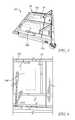
- FIG. 2is a perspective view of a footboard of the patient bed of FIG. 1 showing an outline of a space within the footboard for receiving a compression module that houses pneumatic and electrical components which operate to inflate and deflate the compression sleeves;
- FIG. 3is a side view of the footboard of FIG. 2 showing an outline of a portion of the space that receives the compression module;
- FIG. 4is an enlarged perspective view of a bottom of the footboard showing an outline of a portion of the space that receives the compression module;
- FIG. 5is perspective view of an underside of a foot section of a mattress support deck of the patient bed of FIG. 1 showing an outline of a space on the underside of the foot section for receiving a compression module in an alternative embodiment
- FIG. 6is a bottom plan view of the foot section of FIG. 5 showing the outline of the space that receives the compression module;
- FIG. 7is a block diagram showing electrical and pneumatic components of the patient bed of FIG. 1 and showing a pair of compression therapy modules (in phantom) with one of the compression therapy modules being housed inside the footboard according to one embodiment of the patient bed and the other of the compression therapy modules being located on an extender portion of a foot section according to a second embodiment of the patient bed;
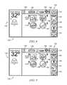
- FIG. 8is a screen shot of a home screen that appears on a graphical user interface (GUI) of the patient bed of FIG. 1 , the home screen having a vertical menu bar on the right hand side of the screen;
- GUIgraphical user interface
- FIG. 9is a screen shot showing the vertical menu bar at the right hand side of the screen scrolled so that a compression therapy icon appears on the menu bar;
- FIG. 10is a screen shot of a generic compression therapy device control screen which appears on the GUI in response to selection of the compression therapy icon and which represents various screens used to control the compression therapy;
- FIG. 11is cross sectional view of a footboard having a compression module integrated therein showing a set of arrows to indicate air flow into and out of an interior region of the footboard from ambient atmosphere and into and out of the compression module from the interior region of the footboard;
- FIG. 12is a rear perspective view showing a rear of a housing of the compression module of FIG. 11 ;
- FIG. 13is an enlarged perspective view of a bottom region of the footboard of FIG. 11 showing an electrical cable hanging downwardly through a hole in the bottom of the footboard and showing the hole being sufficiently large to permit air to enter and exit the interior region of the footboard around the cable;
- FIG. 14is cross sectional view of the compression module of FIGS. 11 and 12 showing internal components of the compression module;
- FIG. 15is an enlarged perspective view showing the compression module of FIGS. 11 and 12 arranged for insertion into a module-receiving cavity of the footboard;
- FIG. 16is a block diagram of an alternative embodiment of a compression module showing that the compression module receives power wirelessly from the bed circuitry via inductively coupled coils and that communicates wirelessly with the bed circuitry via communicatively coupled transceivers and showing a set of heater/cooler units to introduce heated and/or cooled air into the air flow between the pump and a pair of connectors to which respective compression sleeves couple.
- a patient support apparatussuch as illustrative hospital bed 10
- a patient support structuresuch as a frame 20 that supports a surface or mattress 22 as shown in FIG. 1 .
- apparatus 10is embodied as a hospital bed 10
- this disclosureis applicable to other types of patient support apparatuses, including other types of beds, surgical tables, examination tables, stretchers, and the like.
- a graphical user interface (GUI) 142 of bed 10is operable to control operation of a limb compression device and to control features or functions of bed 10 .
- GUI 142is also referred to herein as a graphical display screen 142 .
- the limb compression device disclosed hereinincludes a compression therapy module 23 , shown diagrammatically in FIG. 7 , which is integrated into bed 10 and one or more compression sleeves 25 that are placed upon a patient's limbs as shown, for example, in FIG. 1 .
- Sleeves 25are configured as wraps in some embodiments that are sized to wrap about a patient's calves, thighs, and/or feet. Combination sleeves that attach to a patient's calves and feet or that attach to a patient's calves and thighs or that attach to a patient's feet, calves and thighs are within the scope of this disclosure.
- Sleeves that attach to a patient's arms or torsoare also within the scope of this disclosure. However, sleeves that attach to a patient's legs are the ones that are most commonly used in the healthcare environment, particularly, for the prevention of deep vein thrombosis (DVT).
- DVDdeep vein thrombosis
- the compression therapy devices disclosed hereinare sometimes referred to as sequential compression devices (SCD's) or intermittent compression devices (ICD's) or deep vein thrombosis (DVT) prevention systems or the like.
- SCD'ssequential compression devices
- ICD'sintermittent compression devices
- DVDdeep vein thrombosis
- these terms and variants thereofare used interchangeably herein to cover all types of devices and systems that have compression sleeves with one or more inflatable and deflatable chambers that are controlled pneumatically by delivery and removal of air or other gas from a set of pneumatic components that are usually, but not necessarily, contained within a housing.
- frame 20 of bed 10includes a lower frame or base 28 , an upper frame assembly 30 and a lift system 32 coupling upper frame assembly 30 to base 28 .
- Lift system 32is operable to raise, lower, and tilt upper frame assembly 30 relative to base 28 .
- Bed 10has a head end 24 and a foot end 26 .
- Bed 10further includes a footboard 45 at the foot end 26 and a headboard 46 at the head end 24 .
- Headboard 46is coupled to an upstanding portion 27 of base 28 .
- Footboard 45is coupled to an extendable and retractable portion 47 of a foot section 44 of a patient support deck 38 of upper frame assembly 30 as will be described in more detail below.
- footboard 45is coupled to a foot end of upper frame assembly 30 .
- Base 28includes wheels or casters 29 that roll along a floor as bed 10 is moved from one location to another.
- a set of foot pedals 31are coupled to base 28 and are used to brake and release casters 29 as is known in the art.
- Illustrative hospital bed 10has four siderail assemblies coupled to upper frame assembly 30 as shown in FIG. 1 .
- the four siderail assembliesinclude a pair of head siderail assemblies 48 (sometimes referred to as head rails) and a pair of foot siderail assemblies 50 (sometimes referred to as foot rails).
- Each of the siderail assemblies 48 , 50is movable between a raised position, as shown in FIG. 1 , and a lowered position (not shown but well-known to those skilled in the art).
- Siderail assemblies 48 , 50are sometimes referred to herein as siderails 48 , 50 .
- Each siderail 48 , 50includes a barrier panel 54 and a linkage 56 .
- Each linkage 56is coupled to the upper frame assembly 30 and is configured to guide the barrier panel 54 during movement of siderails 48 , 50 between the respective raised and lowered positions.
- barrier panel 54is maintained by the linkage 56 in a substantially vertical orientation during movement of siderails 48 , 50 between the respective raised and lowered positions.
- siderails that do not remain in a vertical orientation during raising and loweringare within the scope of this disclosure as are siderails that completely detach from the associated bed.
- Beds without any siderailsare also within the scope of the present disclosure, in which case user inputs shown on siderails 48 of bed 10 and described below are provided on some other portion of bed 10 , such as footboard 45 or headboard 46 , or on a handheld controller 67 .
- Upper frame assembly 30includes a patient support deck 38 that supports mattress 22 .
- Patient support deck 38is situated over an upper frame 39 of frame assembly 30 .
- Patient support deck 38includes a head section 40 , a seat section 42 , a thigh section 43 and a foot section 44 in the illustrative example as shown in FIG. 1 and as shown diagrammatically in FIG. 7 .
- Sections 40 , 43 , 44are each movable relative to upper frame 39 .
- head section 40pivotably raises and lowers relative to seat section 42
- foot section 44pivotably raises and lowers relative to thigh section 43 .
- thigh section 43articulates relative to seat section 42 .
- foot section 44is extendable and retractable to change the overall length of foot section 44 and therefore, to change the overall length of deck 38 .
- foot section 44includes a first portion 49 and a second portion or extender 47 in some embodiments as shown diagrammatically in FIG. 7 .
- seat section 42is fixed in position with respect to upper frame 36 as patient support deck 38 moves between its various patient supporting positions including a horizontal position, shown diagrammatically in FIG. 7 , to support the patient in a supine position, for example, and a chair position (not shown) to support the patient in a sitting up position.
- seat section 42also moves relative to weigh frame 36 , such as by pivoting and/or translating. If desired, in those embodiments in which seat section 42 translates along upper frame 42 , the thigh and foot sections 43 , 44 also translate along with seat section 42 .
- foot section 44lowers relative to thigh section 43 and, in some embodiments, shortens in length due to retraction of the extender 47 relative to first portion 49 .
- foot section 44raises relative to thigh section 43 and increases in length due to extension of extender 47 relative to first portion 49 .
- head section 40extends upwardly from upper frame 36 and foot section extends downwardly from thigh section 43 .
- the thigh section 43may tilt upwardly relatively to seat section 42 as bed 10 moves into the chair position in some embodiments.
- bed 10includes a head motor or actuator 90 coupled to head section 40 , a knee motor or actuator 92 coupled to thigh section 43 , a foot motor or actuator 94 coupled to foot section 44 , and a foot extension motor or actuator 96 coupled to first portion 49 and extender 47 of foot section 44 .
- Motors 90 , 92 , 94 , 96may include, for example, an electric motor of a linear actuator.
- a seat motor or actuator(not shown) is also provided.
- Head motor 90is operable to raise and lower head section 40
- knee motor 92is operable to articulate thigh section 43 relative to seat section 42
- foot motor 94is operable to raise and lower foot section 44 relative to thigh section 43
- foot extension motor 96is operable to extend and retract extender 47 of foot section 44 relative to first portion 44 of foot section 44 .
- Bed 10includes an angle sensor 41 coupled to head section 40 and electrically coupled to circuitry 98 as shown in FIG. 7 .
- Angle sensor 41comprises an accelerometer, inclinometer, or the like in some embodiments.
- angle sensor 41comprises a potentiometer, such as a potentiometer included in head motor 90 or a potentiometer having a housing fixed with respect to upper frame 39 , for example, and having a rotatable input shaft coupled to head section 40 to rotate as the head section 40 raises and lowers.
- its outputis provided to control circuitry 98 and correlates to an angle of head section 40 relative to gravity or horizontal or relative to upper frame 39 , as the case may be.
- circuitry 98receives feedback from one or more angle sensors regarding the angular orientation of each of the movable portions, such as upper frame 39 and sections 40 , 43 , 44 of frame 20 .
- mattress 22is an air mattress that contains one or more air bladders or layers 73 as shown diagrammatically in FIG. 7 .
- bed 10includes a pneumatic system 72 that controls inflation and deflation of the various air bladders or cells and/or layers of air mattress 22 .
- the pneumatic system 72is represented in FIG. 7 as a single block but that block 72 is intended to represent one or more air sources (e.g., a fan, a blower, a compressor) and associated valves, manifolds, air passages, air lines or tubes, pressure sensors, and the like, as well as the associated electric circuitry, that are typically included in a pneumatic system for inflating and deflating air bladders of mattresses of patient beds.
- lift system 32 of bed 10includes one or more elevation system motors or actuators 70 , which in some embodiments, comprise linear actuators with electric motors.
- actuators 70are sometimes referred to herein as motors 70 .
- Alternative actuators or motors contemplated by this disclosureinclude hydraulic cylinders and pneumatic cylinders, for example.
- the motors 70 of lift system 32are operable to raise, lower, and tilt upper frame assembly 30 relative to base 28 .
- one of motors 70is coupled to, and acts upon, a set of head end lift arms 78 and another of motors 70 is coupled to, and acts upon, a set of foot end lift arms 80 to accomplish the raising, lowering and tilting functions of upper frame assembly 30 relative to base 28 .
- Guide linksare coupled to base 28 and to lift arms 80 in some embodiments.
- lift system 32 of bed 10is substantially similar to the lift system of the VERSACARE® bed available from Hill-Rom Company, Inc.
- Other aspects of bed 10are also substantially similar to the VERSACARE® bed in some embodiments and are described in more detail in U.S. Pat. Nos.
- Each siderail 48includes a first user control panel 66 coupled to the outward side of the associated barrier panel 54 and each siderail 50 includes mounting features for a second user control panel 67 , which is provided on a handheld control unit which is sometimes referred to in the art as a pendant.
- Control panel 66is adjacent to, but spaced from GUI 142 .
- Controls panels 66 , 67include various buttons that are used by a caregiver (not shown) or a patient in the case of control panel 67 , to control associated functions of bed 10 .
- control panels 66 , 67include buttons that are used to operate head motor 90 to raise and lower the head section 40 , buttons that are used to operate knee motor 92 to raise and lower the thigh section, and buttons that are used to operate motors 70 to raise, lower, and tilt upper frame assembly 30 relative to base 28 .
- control panels 66 , 67include buttons that are used to operate motor 94 to raise and lower foot section 44 and buttons that are used to operate motor 96 to extend and retract foot extension 47 relative to main portion 49 .
- some buttons included on control panel 66are omitted from control panel 67 .
- buttons to operate motors 70 , 96are omitted from control panel 67 in some embodiments.
- the buttons of control panels 66 , 67comprise membrane switches.
- bed 10includes control circuitry 98 that is electrically coupled to motors 90 , 92 , 94 , 96 and to motors 70 of lift system 32 .
- Control circuitry 98is represented diagrammatically as a single block 98 in FIG. 7 , but control circuitry 98 in some embodiments comprises various circuit boards, electronics modules, and the like that are electrically and communicatively interconnected.
- Control circuitry 98includes one or more microprocessors 172 or microcontrollers that execute software to perform the various bed control functions and algorithms along with compression device control functions and algorithms as described herein.
- circuitry 98also includes memory 174 for storing software, variables, calculated values, and the like as is well known in the art.
- a user inputs blockrepresents the various user inputs such as buttons of control panels 66 , 67 , for example, that are used by the caregiver or patient to communicate input signals to control circuitry 98 of bed 10 to command the operation of the various motors 70 , 90 , 92 , 94 , 96 of bed 10 , as well as commanding the operation of other functions of bed 10 .
- Bed 10includes at least one graphical user input (GUI) or display screen 142 coupled to a respective siderail 48 as shown in FIG. 1 .
- Display screen 142is coupled to control circuitry 98 as shown diagrammatically in FIG. 7 .
- two GUI's 142are provided and are coupled to respective siderails 48 .
- GUI 142is coupled to siderails 50 and/or to one or both of the headboard 46 and footboard 45 .
- a GUI 142may be coupled to any of barriers 45 , 46 , 48 , 50 of bed 10 .
- GUI 142is provided on a hand-held device such as a tablet, phone, pod or pendant that communicates via a wired or wireless connection with control circuitry 98 .
- Control circuitry 98receives user input commands, sometimes referred to herein as simply “user inputs,” from GUI 142 when display screen 142 is activated.
- the user input commandscontrol various functions of compression therapy module 23 and various functions of bed 10 such as controlling the pneumatic system 72 and therefore, the surface functions of surface 22 .
- surface 22is not controlled by GUI 142 .
- the input commands entered on GUI 142also control the functions of one or more of motors 70 , 90 , 92 , 94 , 96 but this need not be the case.
- input commands entered on the user interface 142also control functions of a scale system 270 , which is discussed in more detail below.
- control circuitry 98 of bed 10communicates with a remote computer device 176 via communication infrastructure 178 such as an Ethernet of a healthcare facility in which bed 10 is located and via communications links 177 , 179 as shown diagrammatically in FIG. 7 .
- Infrastructure 178may be operated according to, for example, the IEEE 802.3 (wired Ethernet) standard and/or the IEEE 802.11 (wireless Ethernet or WiFi) standard.
- Computer device 176is sometimes simply referred to as a “computer” or a “server” herein.
- control circuitry 98 of bed 10communicates with one or more in-room computers or displays 181 via communication infrastructure 178 and via communications link 183 .
- display 181is a room station of a nurse call system.
- Remote computer 176may be part of a bed data system, for example.
- a bed data systemis shown and described in U.S. Patent Application Publication No. 2012/0316892 A1 which is hereby incorporated herein by reference to the extent that it is not inconsistent with the present disclosure which shall control as to any inconsistencies.
- circuitry 98 of bed 10to communicate with other computers 176 or servers 176 such as those included as part of an electronic medical records (EMR) system, a nurse call system, a physician ordering system, an admission/discharge/transfer (ADT) system, or some other system used in a healthcare facility in other embodiments, although this need not be the case.
- Ethernet 178 in FIG. 2is illustrated diagrammatically and is intended to represent all of the hardware and software that comprises a network of a healthcare facility.
- bed 10has a communication interface or port 180 which provides bidirectional communication via link 177 with infrastructure 178 which, in turn, communicates bidirectionally with computers 176 , 181 via links 179 , 183 respectively.
- Link 177is a wired communication link in some embodiments and is a wireless communications link in other embodiments.
- communications link 177in some embodiments, comprises a cable that connects bed 10 to a wall mounted jack that is included as part of a bed interface unit (BIU) or a network interface unit (NIU) of the type shown and described in U.S. Pat. Nos. 7,538,659 and 7,319,386 and in U.S. Patent Application Publication Nos.
- communications link 179comprises wireless signals sent between bed 10 and a wireless interface unit or a wireless access point of the type shown and described in U.S. Patent Application Publication No. 2007/0210917 A1 which is hereby expressly incorporated by reference herein to the extent that it is not inconsistent with the present disclosure which shall control as to any inconsistencies.
- communications links 179 , 183each comprises one or more wired links and/or wireless links as well, according to this disclosure.
- circuitry 98is coupled to scale system 270 as mentioned above.
- Scale system 270includes one or more sensors (not shown) that are used to detect weight of the patient and/or the movement of the patient on bed 10 and/or the exit of the patient from bed 10 .
- the sensors of scale system 270are load cells that are included as part of bed frame 20 .
- the load cellseach include strain gage elements that are mounted to a mass of material, such as a metal material like aluminum, and that change resistance based on an amount that the mass of material of the load cell is deflected.
- a discussion of how the use of load cells as sensors of scale system 270 may provide different bed exit modes of varying levels of sensitivitycan be found in U.S. Pat. No. 7,253,366 which is hereby incorporated by reference herein to the extent not inconsistent with the present disclosure which shall control as to any inconsistencies.
- Signals from the load cellsare also used by the scale system 270 of bed 10 to calculate patient weight.
- the sensors of system 270can include other types of sensing devices in other embodiments.
- suitable sensorsmay include force sensitive resistors (FSRs) that are placed beneath the mattress 22 of the bed 10 on the patient support deck 38 .
- FSRsforce sensitive resistors
- U.S. Pat. No. 7,296,312which is already incorporated by reference herein.
- Other examples in which FSRs are used as part of a bed exit alarm systemare shown and described in U.S. Pat. Nos. 7,464,605 and 6,208,250 which are both hereby incorporated by reference herein to the extent not inconsistent with the present disclosure which shall control as to any inconsistencies.
- sensors of scale system 270which serves also as a bed exit and/or patient position monitoring system of bed 10 , can be of one type, such as load cells, FSRs, tape switches, or capacitive sensors, just to name a few, or can be of different types, such as using combinations of the sensors mentioned herein.
- bed 10has one or more alarms 185 such one or more audible alarms and/or one or more visual alarms that are coupled to circuitry 98 .
- Audible alarms 185include, for example, a speaker, piezoelectric buzzer, or the like.
- Circuitry 98commands audible alarms 185 to sound in response to various alarm conditions being detected.
- Visual alarms 185include, for example, one or more alert lights that are provided one frame 20 of bed 10 and that are activated in different ways to indicate the conditions of bed 10 . When no alerts or alarms exist, the lights are activated to shine green, for example.
- lights 88are activated to shine red or amber and, in some embodiments, to blink. Additional details of suitable visual alarms for use in bed 10 are found in U.S. Pat. No. 8,593,284 and in U.S. Patent Application Publication No. 2014/0259410 A1, each of which is hereby incorporated by reference herein to the extent not inconsistent with the present disclosure which shall control as to any inconsistences.
- Other visuals alarmsthat may be used in addition to, or instead of such alert lights, include changing a background color of graphical display screen 142 and/or displaying an iconic or textual alarm message on display screen 142 and may even include IV pole mounted or wall mounted devices such as lights or graphical display screens.
- FIG. 7is diagrammatic in nature and that various portions of bed 10 and the circuitry thereof is not depicted.
- a power source block 202is intended to represent an onboard battery of bed 10 and an AC power cord of bed 10 as well as the associated power handling circuitry.
- an other sensors block 204is intended to represent all of the other sensors of bed 10 such as one or more sensors used to sense whether a caster braking system of bed 10 is in a braked or released position and such as sensors used to detect whether each of the siderails 48 , 50 is raised or lowered, just to name a few.
- bed 10includes compression therapy module 23 which operates to inflate and deflate one or more compression sleeves 25 .
- module 23is located inside of footboard 45 .
- Footboard 45has a pair of mounting posts 102 , one of which can be seen in FIG. 4 , that are received in sockets 104 shown in FIG. 2 .
- a 14 inch-by-8 inch-by-4 inch spaceis depicted diagrammatically in FIGS. 2-4 by outline 106 .
- Outline 106represents the maximum space occupied by module 23 inside footboard 45 in the illustrative example of bed 10 . As shown in FIG. 3 , the particular prototype of footboard 45 needs to have its depth in the longitudinal dimension of bed 10 increased to accommodate module 23 .
- an electrical connector and a pneumatic connectorwhich may be separate connectors in some embodiments and which may be a combined electrical/pneumatic connector in other embodiments, is provided at a bottom surface 108 of footboard 45 .
- Mating electrical and pneumatic connectorsare provided on frame 20 and, in particular, on an upper surface 110 at foot end 26 of extender 47 of foot section 44 .
- Bed 10includes a pair of sleeve ports 112 mounted to respective side surfaces 114 of extender 47 as shown in FIGS. 1-3 .
- Compression sleeves 25have conduits 113 , such as tubes or hoses that are removably connectable to sleeve ports 112 .
- a multi-port connectoris provided at the distal end of conduits 113 to permit simultaneous attachment of multiple conduits 113 to an associated sleeve port 112 .
- One or more pneumatic conduitsare routed from the pneumatic connector on surface 110 at the foot end 26 of extender 47 to each sleeve port 112 of the pair of sleeve ports 112 .
- the first and second pneumatic connectorsi.e., the pneumatic connectors on the footboard 45 and extender 47
- the conduits routed to sleeve ports 112are represented diagrammatically in FIG. 7 as dotted line 116 .
- Electrical lines 118are routed to control circuitry 98 via the first and second electrical connectors (i.e., the pneumatic connectors on the footboard 45 and extender 47 ).
- electrical lines 118provide for bidirectional communication between circuitry 98 and module 23 .
- the electrical lines 118also provide power from power source 202 to control module 22 via control circuitry 98 in the illustrative example.
- no separate power cordis needed for compression module 23 because it receives power from the bed 10 in which it is integrated.
- Lock 120is provided at the interface between footboard 45 and extender 47 .
- Lock 120may comprise an extendable and retractable pin, such as a pin operated by a solenoid, or some other type of movable member such as a catch, hook, pawl, lever, or the like that is mounted on extender 47 and that is moved by an electrically operated driver to a locked position for receipt in an aperture, pocket, opening, or the like provided in footboard 45 to retain or lock footboard 45 on extender 47 .
- Such an openingmy comprise a hole or notch in one of mounting posts 102 of footboard 45 , for example.
- the pin or other movable memberis movable to a released position to permit footboard 45 to be detached from extender 47 .
- circuitry 98sends one or more commands to lock 120 to signal lock 120 to operate in a locked mode having the pin or other movable member in the locked position when module 23 is turned on and operating to inflate and deflate one or more compression sleeves 25 .
- circuitry 98sends one or more commands to lock 120 to signal lock 120 to operate in a released or unlocked mode having the pin or other movable member in the released position so that footboard 45 is removable from extender 47 of foot section 44 of frame 20 .
- footboard 45cannot be removed from extender 47 in some embodiments.
- compression therapy module 23is mounted to an underside or undersurface 122 of extender 47 of foot section 44 .
- An 11 inch-by-8 inch-by-4 inch spaceis depicted diagrammatically in FIGS. 5 and 6 by outline 106 ′.
- Outline 106 ′represents the maximum space occupied by module 23 underneath extender 47 of foot section 44 in the illustrative example of bed 10 .
- the conduits extending between compression therapy module 23 and sleeve ports 112do not require any intermediate pneumatic couplers like the embodiment of FIGS. 2-5 , although this is not to exclude the possibility that such intermediate connectors may be used, if desired.
- conduits 116 ′are illustrated diagrammatically in FIG. 7 .
- One or more electrical lines 118 ′extend between the compression therapy module 23 mounted to extender 47 and control circuitry 98 as indicated diagrammatically in FIG. 7 .
- the discussion above of electrical lines 118is equally applicable to electrical lines 118 ′.
- a home screen 130which appears on GUI 142 as a default screen includes a vertical menu bar 132 on the right hand side of screen 130 .
- Menu bar 132includes a home screen icon 133 which is selected to an alarm button or icon 134 which is selected to navigate to a screen that permits management of alarms of bed 10 , a scale icon 136 which is pressed to navigate to a first scale screen of a plurality of scale screens, a Bluetooth icon 138 which is selected to navigate to a screen that permits management of Bluetooth connectivity between bed 10 and other devices, and a down arrow icon 140 which is selected to scroll to other icons of menu bar 132 .
- a fieldindicates an angle at which head section 38 of bed 10 is elevated (32 degrees in the illustrative example) as measured by angle sensor 41 as described above.
- an alarm icon 144 with an “X” superimposed thereonappears beneath the angle measurement data on screen 130 to indicate that no alarms are occurring presently.
- Screen 130includes a horizontal informational bar across the top thereof which includes a help icon 146 which is selected to navigate to a first help screen of a plurality of help screens, a battery charge level icon 148 which indicates a level of charge of a battery of bed 10 , an “N” icon which indicates successful communication with a nurse call system, a room number (e.g., room “123A” in the illustrative example), a WiFi icon 150 to indicate that the bed is in successful wireless communication with a WiFi access point of network 178 , and a Bluetooth icon 152 to indicate that the bed is in successful wireless communication with at least one other Bluetooth-enabled device or component such as a communicator/locator unit mounted to a room wall.
- a help icon 146which is selected to navigate to a first help screen of a plurality of help screens
- a battery charge level icon 148which indicates a level of charge of a battery of bed 10
- an “N” iconwhich indicates successful communication with a nurse call system
- a room number
- Screen 130also includes four user input buttons in a window or field beneath the horizontal informational bar as shown in FIGS. 8 and 9 .
- the four buttonsinclude a head limit button 154 which is selected to prevent the head section 40 of bed 10 from lowering to an elevation less than 30 degrees; a chair egress button 156 which is selected when a patient is about to egress from bed 10 to cause a seat region of mattress 22 to inflate to a higher target pressure (e.g., max inflate), to lower the thigh and foot sections 43 , 44 if they are raised when button 156 is selected, and to raise head section 40 if it is lowered below a target elevation when button 156 is selected.
- a head limit button 154which is selected to prevent the head section 40 of bed 10 from lowering to an elevation less than 30 degrees
- a chair egress button 156which is selected when a patient is about to egress from bed 10 to cause a seat region of mattress 22 to inflate to a higher target pressure (e.g.,
- the four buttonsalso include a flat button 158 which is pressed to simultaneously move the head, thigh and foot sections 40 , 43 , 44 to a flat position relative to upper frame 39 (i.e., so as to be substantially coplanar with seat section 42 ) and a chair position button 160 which is selected to simultaneously move sections 40 , 43 , 44 into a chair position. It should be understood that the simultaneous movement occurs, if at all, for those sections 40 , 43 , 44 that are not already in the respective target orientations and that some sections 40 , 43 , 44 may continue to move after others have reached the respective target orientations.
- buttons 156 , 158 , 160results, in some embodiments, in pressure adjustments being made to one or more bladders or layers 73 by pneumatic system 72 based on signals from control circuitry 98 .
- a lock out iconis situated adjacent to each of buttons 154 , 156 , 158 , 160 on screen 130 and each lock out icon is lit or otherwise illuminated or displayed in a manner so as to indicate that the function of the associated button 154 , 156 , 158 , 160 has been locked out and that the button 154 , 156 , 158 , 160 cannot be used.
- screen 130appears but with menu bar 132 having been scrolled by one position so that a compression therapy icon 162 is included in menu bar 132 beneath icon 138 and above icon 140 .
- An up arrow icon 164also appears on menu bar 132 as a result of the scrolling of menu bar 132 .
- screen 130 of FIG. 9is the same as screen 130 of FIG. 8 .
- a first DVT System Control Screen 170 of a plurality of control screens for the compression device of bed 10appears on GUI 142 as shown in FIG. 10 .
- Screen 170 shown in FIG. 10is a “generic” screen which is intended to represent all screens that are used to control operation of module 23 in connection with inflating and deflating one or more compression sleeves 25 .
- a sleeve type block 190 on screen 170 of FIG. 10generically represents one or more sleeve type selection buttons that may appear on screen 170 .
- buttons for selection by a user of left and/or right foot sleeves, left and/or right calf sleeves, left and/or right thigh sleeves, or left and/or right combination sleeves such as those described aboveappear on screen 170 in some embodiments.
- the compression sleeve 25 on a patient's left legmay be of a different type than that on the patient's right leg.
- module 23is operable to determine which type of sleeve is connected to each of ports 112 based on a time it takes to inflate a particular sleeve to a target pressure as measured by a pressure sensor of module 23 . After module 23 makes the sleeve type determination for the one or more sleeves coupled to port(s) 112 , that information is communicated to circuitry 98 which operates to display the sleeve type information on GUI 142 .
- sleeve ports 112include sensors (e.g., Hall Effect sensors, RFID sensors, near field communication (NFC) sensors, or the like) to sense tokens (e.g., magnets, RFID tags, NFC tags, etc.) included as part of the connectors at the distal ends of conduits 113 of sleeves 25 .
- sensorse.g., Hall Effect sensors, RFID sensors, near field communication (NFC) sensors, or the like
- tokense.g., magnets, RFID tags, NFC tags, etc.
- module 23which, in turn, communicates the sleeve type information to circuitry 98 for ultimate display on GUI in connection with the compression device control screens 170 .
- a therapy settings block 192 on screen 170 of FIG. 10generically represents various therapy setting buttons or icons or therapy data entry fields or menus that appear on screen 170 .
- the selectable therapy settings selectable by these various type of user inputsinclude, for example, the target pressure to which each sleeve 25 is to be inflated by module 23 or to which each zone of each sleeve 25 is to be inflated by module 23 if sleeve 23 has multiple zones which is oftentimes the case for sleeves used for sequential compression therapy.
- the selectable therapy settingsfurther include, for example, the frequency of inflation or deflation and/or the duty cycle of the inflation/deflation cycles as well as the number of cycles or the time period over which the compression therapy is to take place.
- the selectable therapy settingsinclude selection of pressure versus time curves (e.g., step up and/or step down curves, ramp up and/or ramp down curves, saw tooth curves, and the like) as well as the parameters for the various types of curves (e.g., pressure setting at each step, duration of each step, duration of ramp up, duration of ramp down, and the like).
- pressure versus time curvese.g., step up and/or step down curves, ramp up and/or ramp down curves, saw tooth curves, and the like
- parameters for the various types of curvese.g., pressure setting at each step, duration of each step, duration of ramp up, duration of ramp down, and the like.
- the manner in which compression therapy is delivered by module 23 to one or more sleeves 25is varied in response to movement of bed components or in response to conditions detected by sensors of bed 10 .
- the manner of compression therapymeans that at least one parameter of operation of module 23 such as a target pressure, a frequency of inflation or deflation, a duration of inflation or deflation, a duty cycle of inflation and deflation, a number of cycles or a time period of compression therapy, a step parameter or a ramp parameter is adjusted either by increasing the particular parameter(s) or decreasing the particular parameter(s).
- control circuitry 98varies an operating parameter of compression therapy of the compression therapy module 23 depending upon the angle of head section 40 as sensed by angle sensor 41 in some embodiments.
- the adjustmentmay be proportional to the angle sensed by angle sensor 41 (e.g., target pressure is a function of head angle) or the adjustment may be based on a look up table which correlates a target pressure or target pressure adjustment offset with the head angle. For example, a first target pressure for sleeve 25 is used when head section 40 is elevated from 0 degrees to 30 degrees, a second target pressure is used when head section 40 is elevated from 30 degrees to 50 degrees and a third target pressure is used when head section 40 is above 50 degrees, just to give one arbitrary example.
- a duty cycle of inflation/deflationmay be adjusted so that the sleeves 25 are inflated for a longer period of time or a shorter period of time within each inflation/deflation cycle. Similar adjustments may be made to the operating parameters of compression therapy based on movement of one or more of sections 43 , 44 of bed 10 . The adjustment is made to compensate for changing elevation of the patient's heart relative to the patient's legs which may have a tendency to affect the blood flow within the patient's legs.
- control circuitry 98varies an operating parameter of compression therapy of the compression therapy module 23 depending upon the weight of the patient sensed by the scale system 270 .
- a heavier patientmay have higher target pressures established for sleeves 112 than a lighter patient.
- control circuitry 98signals the compression therapy module 23 to cease operating if the patient is sensed by the patient position monitoring system to have violated a boundary condition such as being out of position or moving toward exiting bed 10 .
- circuitry 98may signal compression therapy module 23 to cease operating in response to one or more of siderails 49 , 50 being moved out of its raised position and/or in response to side egress button 156 being selected. In these scenarios, the assumption is that a caregiver is present in the room and is getting ready to help the patient to get out of bed 10 .
- control circuitry 98receives information communicated from remote computer 176 over network 178 and varies an operating parameter of compression therapy of the compression therapy module 23 depending upon the information received from the remote computer.
- computer 176may send information to bed 10 indicating that the patient is scheduled for labs or physical therapy or an X-ray or discharge from the healthcare facility at a certain time of day.
- circuitry 98may signal compression module 23 to cease operation a threshold amount of time, selectable by a user in some embodiments, such as 15 or 30 minutes prior to the scheduled event. In this scenario, the assumption is that a caregiver will soon be arriving to remove the patient from bed 10 and taking the patient to the scheduled event.
- computer 176may determine that the patient on bed 10 has become at elevated risk for developing a pressure ulcer, possibly due to conditions sensed on bed 10 such as lack of movement, incontinence, skin shear due to number of movements of one or more of sections 40 , 43 , 44 , use of a heel relief function of mattress 22 , and so on.
- circuitry 98communicates the information to module 23 which may decrease a target pressure of compression therapy or reduce the number of cycles or time period of compression therapy.
- control circuity 98is configured to send information regarding usage of the compression therapy module 23 to remote computer 176 over network 178 .
- control circuitry 98is configured to send information regarding usage of the compression therapy module 23 to in-room display 181 which is spaced from bed 10 .
- the in-room display 181may comprise a graphical station of a nurse call system or it may comprise an in-room computer or it may comprise a hand held computer device such as a phone, laptop computer, or tablet computer.
- control circuitry 98is configured to lock out at least one bed function in response to the compression therapy module 23 being in use.
- the at least one bed function that may be locked outmay include movement of at least one deck section 40 , 43 , 44 of the plurality of deck sections.
- alarms 185are activated in response to alarm conditions associated with compression module 23 .
- alarm conditionsmay include high temperature within module 23 , an electrical short in module 23 , high current or voltage in module 23 , pressure sensor failure within module 23 , and so on.
- alarm messages and error messages regarding the operation of module 23are displayed on GUI 142 in some embodiments.
- module 23 and sleeves 25are made by Encompass Group LLC and are similar in construction and function to the LOGIXTM PULSTAR® DVT Prevention System which is marketed by the ALBAHEALTH® division of Encompass Group LLC.
- GUI 142 of bed 10displays screens 170 that are substantially similar to the screens that appear on a display screen of the LOGIXTM PULSTAR® device.
- the display screen of the LOGIXTM PULSTAR® deviceis not a touchscreen display but instead uses manual buttons adjacent to the display screen, the manual buttons of the LOGIXTM PULSTAR® device are fashioned as touchscreen inputs on GUI 142 of bed 10 .
- footboard 45is shown in cross section and has compression therapy module 23 , sometimes referred to as compression module 23 or just module 23 , mounted therein.
- Footboard 45has an interior region 300 and compression therapy module 23 has a housing 304 with an interior region 302 .
- Housing 304 of module 23is received in a portion 300 ′ of interior region 300 of footboard 45 which is generally rectangular in shape as defined by boundary walls 305 , two of which can be seen in FIG. 15 , of footboard 45 .
- Footboard 45includes a pair of posts 386 that mount to reinforced portions 387 of footboard 45 in interior region 300 using suitable fasteners 388 such as screw, bolts, or rivets. Lower regions of posts 386 extend downwardly from a bottom of footboard 45 and are configured for receipt in mating sockets of frame 30 of bed 10 as is generally known in the art.
- Housing 304includes a generally flat face plate 307 and a shaped rear shell 309 that mounts to a rear of face plate 307 with suitable fasteners such as bolts or screws 311 as shown in FIG. 12 .
- Interior region 302 of module 23is defined between rear shell 309 and face plate 307 .
- Compression module 23is sometimes referred to a pod or a cartridge and any of these synonyms serves as a suitable definition of the others in accordance with this disclosure.
- Face plate 307extends beyond the sides of rear shell 309 and the peripheral side portions of face plate 307 each have a set of holes 313 formed therethrough as shown in FIGS. 12 and 15 .
- An upper wall of shell 309is formed to include a central notch 315 through which an additional hole 313 ′ formed in the top, central region of face plate 307 is accessible at the rear of housing 304 .
- Suitable fasteners 317such as screws or bolts, extend through holes 313 , 313 ′ and thread into respective bosses 319 which are located in portion 300 ′ of interior region 302 adjacent to boundary walls 305 as show in FIG. 15 (portions of only five of the seven bosses 319 can be seen in FIG. 15 ).
- fasteners 317mount housing 304 of module 23 to footboard 45 in the illustrated example.
- Covers or plugs 321are received in complementary shaped depressions or recesses 323 formed in a front of face plate 307 to block access to fasteners 317 after module 23 is mounted to footboard 45 .
- Covers 321are press fit into depressions 323 and/or have adhesive backing for retention in depressions 323 .
- module 23 of FIGS. 11-15can only be removed with the use of tools and only after covers 321 are destructively removed from depressions 323 in some instances.
- module 23 of FIGS. 11-15is considered to be permanently mounted or permanently coupled to footboard 45 according to the present disclosure.
- the connection between the generally rectangular outer periphery of face plate 307 and the generally rectangular opening in footboard 45 to portion 300 ′ of interior region 300forms a substantially airtight and watertight seal.
- module 23includes a circuit board 306 (aka circuitry 306 ) that controls the operation of a motor 308 of a pump 310 of module 23 with signals provided on a wire 397 or other suitable conductor.
- Module 23also includes a first solenoid 312 and a second solenoid 314 that are controlled by circuitry of circuit board 306 via respective wires or conductors 399 .
- An electrical cable 316is routed into interior region 300 of footboard 45 through an opening 318 formed in a bottom wall 327 of footboard 45 , as shown best in FIG. 13 , and through interior regions 300 , 300 ′ of footboard 45 to circuit board 306 though an opening 320 provided in a wall 322 of housing 304 as shown best in FIG.
- Openings 318 , 320are each larger than an outer diameter of cable 316 so as to provide air passageways into and out of interior region 300 of footboard 45 and into and out of interior region 302 of housing 304 .
- Passageways or openings 395are provided in opposite sidewalls 305 to permit air to flow between interior region 300 and interior region 300 ′.
- Module 23includes an air inlet 324 , illustratively a tube, which is in pneumatic communication with an inlet of pump 310 via additional associated tubing 326 and a filter 328 as shown in FIGS. 11 and 14 .
- air inlet 324illustratively a tube, which is in pneumatic communication with an inlet of pump 310 via additional associated tubing 326 and a filter 328 as shown in FIGS. 11 and 14 .
- Module 23includes a pair of pressure hoses 342 that tap into a junction between associated pairs of hoses 336 that are coupled to respective solenoids 312 , 314 . Pressure hoses 342 lead from their respective junctions to pressure sensors 344 of circuit board 306 as shown in FIG. 14 .
- hose connectors 338 , 340are located outside of housing 304 , as shown best in FIG. 12 , so as to be exposed for coupling to mating connectors 346 , 348 , shown best in FIG. 15 , that are provided at respective inboard ends of first and second hoses 350 , 352 .
- Hoses 350 , 352extend through openings 395 from interior region 300 ′ into interior region 300 of footboard 45 and terminate at respective connectors or ports 354 , 356 at the outboard ends of hoses 350 , 352 as shown in FIG. 11 .
- Connectors 354 , 356project from footboard 45 at a somewhat downward angle toward the patient supported by the associated bed 10 .
- Conduits 113 extending from sleeves 25connect to ports 354 , 356 to receive pressurized air from pump 310 .
- the solenoids 312 , 314 associated with ports 354 , 356 that are connected to sleeves 25are signaled by the control circuitry via conductors 399 to move to a position allowing air to flow from sleeves 24 , through connectors 354 , 356 , associated hoses 350 , 352 , connectors 338 , 340 , and associated hoses 336 to escape from respective outlets 325 of solenoids 312 , 314 into the interior region 302 of housing 304 .
- Housing 304is packed with sound reducing foam 358 .
- Foam 358is formed to include a series of passageways 360 including passageways 360 leading from outlets 325 of solenoids 312 , 314 into a space 362 around circuit board 306 which communicates with opening 320 .
- Space 362is part of the interior region 302 of housing 304 .
- arrows 330are shown diagrammatically in FIG. 11 to represent the air flow through the various spaces, passageways, tubing, etc. during inflation and deflation of compression sleeves 25 including through openings 318 , 320 and 395 .
- Suitable strain reliefsare provided near openings 318 , 320 to hold cable 316 in place at these locations and are provided near openings 395 to hold hoses 350 , 352 in place at these locations, while at the same time permitting sufficient slack in cable 316 and hoses 350 , 352 to permit them to be manipulated to make the connections with module 23 during installation of module 23 in footboard 45 .
- circuitry 306 of module 23communicates with circuitry 98 of bed 10 and receives power from circuitry 98 of bed 10 via cable 316 .
- footboard 45is secured to bed 10 , such as being bolted to foot section portion 47 . As such, it is not intended for footboard 45 to be removed from bed 10 during ordinary usage.
- cable 316it is possible for cable 316 to be routed from module 23 all the way to circuitry 98 , or at least to a connector provided in close proximity to circuitry 98 . In other embodiments, however, to permit detachment of footboard 45 from bed 10 , cable 316 terminates at a connector 377 which plugs into a mating connector on bed 10 .
- Such a mating connectormay be mounted at or near the foot end 26 of portion 47 of deck 38 , for example.
- matting connectorsmay be provided between a bottom of footboard 45 and the underlying bed support structure such as is shown in U.S. Pat. No. 6,208,250 which is hereby incorporated by reference herein with regard to elements 52 , 54 which are shown and described in connection with FIGS. 1-3 and 14-16 .
- Cable 316includes electrical conductors that are among the conductors interconnecting circuitry 306 of module 23 and circuitry 98 of bed 10 . It should be appreciated that, inputs entered on GUI 142 of bed 10 pertaining to module 23 are communicated from circuitry 98 to circuitry 306 via cable 316 . Information regarding the operation of module 23 are communicated from circuitry 306 of module 23 to circuitry 98 of bed 10 via cable 316 .
- modules 23 manufactured by different companies and/or modules 23 manufactured by the same company but having different features and functionsmay be attached to footboard 45 in the allotted space 300 ′ of footboard 45 .
- cable 316is electrically coupled the module 23 and hoses 350 , 352 are pneumatically coupled to the module being installed.
- Circuitry 98 of bed 10receives information from the circuitry 306 of the particular module which identifies the module type (e.g., model no., manufacturer, etc.). Thus, bed 10 senses the type of module 23 installed in footboard 45 . Circuitry 98 of bed then uses the proper software to communicatively interface with the type of module 23 installed.
- circuitry 98software for all potential types of modules 23 that may be installed in footboard 45 is preloaded and stored in memory 174 of circuitry 98 . Once the type of module 23 has been determined by circuitry 98 , the corresponding software for the particular type of module is then used by circuitry 98 in connection with communicating with module 23 and in connection with presenting user interface screens on GUI 142 .
- circuitry 306 of each module 23stores the particular software that bed circuitry 98 needs for interfacing with the particular type of module 23 and then circuitry 306 downloads the software to circuitry 98 via cable 316 after it is connected to the particular module 23 . Further alternatively or additionally, after bed circuitry 98 determines the type of module 23 installed in footboard 45 , circuitry 98 downloads the appropriate software for the type of module 23 from a remote computer or server having the appropriate software stored therein.
- circuitry 306 of compression module 23receives power wirelessly from bed circuitry 98 and communicates wirelessly with bed circuitry 98 .
- a first coil 400is carried on bed 10 , such as on portion 47 of deck 38 near the foot end 26 of bed 10 , and is coupled to bed circuitry 98 via a wired connection 402 .
- a second coil 404is carried by compression module 23 , such as near the bottom of housing 304 , and is coupled via a wired connection 406 to circuitry 306 .
- coil 404is carried by the footboard 45 and is wired into the compression module 23 via a suitable electrical conductor leading to circuitry 306 .
- circuitry 306includes a battery 408 that is charged with the power provided wirelessly to coil 404 by coil 400 .
- circuitry 306does not include battery 408 and the various electrical components (e.g., circuitry 306 , motor 308 of pump 310 , and solenoids 312 , 314 ) of module 23 are powered directly from coil 404 , optionally with an intervening voltage controller or voltage divider or the like.
- a first transceiver 410is carried on bed 10 such as on portion 47 of deck 38 near the foot end 26 of bed 10 , and is coupled to bed circuitry 98 via a wired connection 412 .
- a second transceiver 414is carried by compression module 23 , such as near the bottom of housing 304 , and is coupled via a wired connection 416 to circuitry 306 .
- transceiver 414is carried by circuit board 306 or is carried by the footboard 45 and is wired into the compression module 23 via a suitable electrical conductor leading to circuitry 306 .
- Transceivers 410 , 414communicate bidirectionally such that data transmitted from circuitry 306 via transceiver 414 is received by circuitry 98 of bed 10 and such that data transmitted from circuitry 98 via transceiver 410 is received by circuitry 306 of module 23 .
- All suitable types of wireless communication protocolsare contemplated by the present disclosure for circuitry 98 , 306 and transceivers 410 , 414 , including, but not limited to, Bluetooth, Bluetooth Low Energy (BLE), IEEE 802.11 of all types, and Zigbee protocols.
- Any of the data and/or software transmissions made using cable 316 discussed above,can be made wirelessly via transceivers 410 , 414 .
- transceivers 410 , 414are omitted and data and/or software transmissions are made between coils 400 , 404 such that data, software, and power is provided over the same wireless link.
- a set of heater/cooler units 420are provided to introduce heated and/or cooled air into the air flow between pump 332 and the connectors 354 , 356 to which respective compression sleeves 25 couple.
- units 420comprise a heater or a cooler or both according to the present disclosure.
- units 420are controlled by circuitry 306 via respective wired connections 422 .
- Arrows 424diagrammatically indicate the heated or cooled air that is introduced by units 420 into the air flow from pump 310 .
- temperature sensorsare provided at a suitable location, such as within units 420 or in one or more of conduits 336 , 350 , 352 , or in one or more of connectors 338 , 340 , 354 , 356 . Signals from the temperature sensors are used by circuitry 306 for feedback control of units 420 so as to maintain the air flow to sleeves 25 at a target temperature within a suitable tolerance range.
- units 420are located inside compression module 23 .
- heater/cooler units 420 ′are located outside of compression module 23 but within footboard 45 as indicated in FIG. 16 (in dotted line).
- units 420are included in the module 23 mounted to foot section 44 and/or units 420 ′ are mounted to foot section 44 separately from the associated module 23 .
- heated and/or cooled airis introduced into the flow of air to that ports 112 that are mounted to foot section 44 .
- units 420 ′introduce heated or cooled air into the air flow from pump 310 via pneumatic couplings with conduits 350 , 352 .
- Each of units 420 ′has a wired connection 422 ′ which leads to either circuitry 306 or circuitry 98 or both.
- units 420 , 420 ′communicate unidirectionally or bidirectionally with circuitry 98 via transceivers 410 , 414 .
- software control of units 420 , 420 ′to be undertaken by either circuitry 306 or circuitry 98 or both.
- only one unit 420 , 420 ′is provided for introducing heated or cooled air into the pneumatic system of module 23 .
- a single unit 420 , 420 ′is coupled to air inlet 324 such that the air flow reaching the inlet of pump 310 is already heated or cooled.
Landscapes
- Health & Medical Sciences (AREA)
- Life Sciences & Earth Sciences (AREA)
- Animal Behavior & Ethology (AREA)
- General Health & Medical Sciences (AREA)
- Public Health (AREA)
- Veterinary Medicine (AREA)
- Epidemiology (AREA)
- Pain & Pain Management (AREA)
- Physical Education & Sports Medicine (AREA)
- Rehabilitation Therapy (AREA)
- Nursing (AREA)
- Invalid Beds And Related Equipment (AREA)
Abstract
Description
Claims (29)
Priority Applications (2)
| Application Number | Priority Date | Filing Date | Title |
|---|---|---|---|
| US15/432,991US10507158B2 (en) | 2016-02-18 | 2017-02-15 | Patient support apparatus having an integrated limb compression device |
| US16/671,598US10952920B2 (en) | 2016-02-18 | 2019-11-01 | Patient support apparatus having an integrated limb compression device |
Applications Claiming Priority (2)
| Application Number | Priority Date | Filing Date | Title |
|---|---|---|---|
| US201662296735P | 2016-02-18 | 2016-02-18 | |
| US15/432,991US10507158B2 (en) | 2016-02-18 | 2017-02-15 | Patient support apparatus having an integrated limb compression device |
Related Child Applications (1)
| Application Number | Title | Priority Date | Filing Date |
|---|---|---|---|
| US16/671,598ContinuationUS10952920B2 (en) | 2016-02-18 | 2019-11-01 | Patient support apparatus having an integrated limb compression device |
Publications (2)
| Publication Number | Publication Date |
|---|---|
| US20170239131A1 US20170239131A1 (en) | 2017-08-24 |
| US10507158B2true US10507158B2 (en) | 2019-12-17 |
Family
ID=58046593
Family Applications (2)
| Application Number | Title | Priority Date | Filing Date |
|---|---|---|---|
| US15/432,991Active2038-03-03US10507158B2 (en) | 2016-02-18 | 2017-02-15 | Patient support apparatus having an integrated limb compression device |
| US16/671,598ActiveUS10952920B2 (en) | 2016-02-18 | 2019-11-01 | Patient support apparatus having an integrated limb compression device |
Family Applications After (1)
| Application Number | Title | Priority Date | Filing Date |
|---|---|---|---|
| US16/671,598ActiveUS10952920B2 (en) | 2016-02-18 | 2019-11-01 | Patient support apparatus having an integrated limb compression device |
Country Status (2)
| Country | Link |
|---|---|
| US (2) | US10507158B2 (en) |
| EP (3) | EP3207911B1 (en) |
Cited By (7)
| Publication number | Priority date | Publication date | Assignee | Title |
|---|---|---|---|---|
| US20200306130A1 (en)* | 2019-03-29 | 2020-10-01 | Hill-Rom Services, Inc. | Control system for a patient therapy device |
| US10952920B2 (en) | 2016-02-18 | 2021-03-23 | Hill-Rom Services, Inc. | Patient support apparatus having an integrated limb compression device |
| US11052004B2 (en)* | 2018-03-23 | 2021-07-06 | Stryker Corporation | Interchangeable side rails for a patient support apparatus |
| US20230064841A1 (en)* | 2020-07-21 | 2023-03-02 | Abohashem Ahmed Abdelsalam Mohamed | Mobile integrated patient support apparatus |
| US11654075B2 (en)* | 2019-03-29 | 2023-05-23 | Hill-Rom Sevices, Inc. | Method and apparatus for upgrading a patient support apparatus to include an integrated patient therapy device |
| US11931312B2 (en) | 2019-03-29 | 2024-03-19 | Hill-Rom Services, Inc. | User interface for a patient support apparatus with integrated patient therapy device |
| US11974964B2 (en) | 2019-03-29 | 2024-05-07 | Hill-Rom Services, Inc. | Patient support apparatus with integrated patient therapy device |
Families Citing this family (15)
| Publication number | Priority date | Publication date | Assignee | Title |
|---|---|---|---|---|
| CA3013769A1 (en) | 2016-02-04 | 2017-08-10 | Roho, Inc. | System and method for cushion inflation |
| AU2017269667B2 (en)* | 2016-05-26 | 2021-07-22 | Arjo Ip Holding Ab | Compression therapy system and method |
| US20180272147A1 (en)* | 2017-03-21 | 2018-09-27 | Zoll Medical Corporation | Wearable defibrillator integrated with remote ischemic conditioning protocol |
| US10285766B2 (en) | 2017-03-29 | 2019-05-14 | Verb Surgical Inc. | Surgical table base construction for heat dissipation from housed power electronics |
| EP3643283A1 (en)* | 2018-10-22 | 2020-04-29 | Hill-Rom Services, Inc. | A system for adjusting the configuration of a patient support apparatus |
| US12042453B2 (en) | 2019-02-26 | 2024-07-23 | Hill-Rom Services, Inc. | Patient positioning apparatus and mattress |
| USD916128S1 (en)* | 2019-03-04 | 2021-04-13 | Apple Inc. | Electronic device with icon |
| WO2020205329A1 (en)* | 2019-04-04 | 2020-10-08 | Kci Licensing, Inc. | Garment including a micro-pump for non-fluid management tissue therapies |
| USD916745S1 (en)* | 2019-05-08 | 2021-04-20 | Sleep Number Corporation | Display screen or portion thereof with graphical user interface |
| CN114929072A (en) | 2020-01-03 | 2022-08-19 | 数眠公司 | Bed gas flow and temperature control |
| US20210307523A1 (en)* | 2020-04-07 | 2021-10-07 | Lg Electronics Inc. | Bed |
| JP6905769B1 (en)* | 2020-06-22 | 2021-07-21 | ファミリーイナダ株式会社 | Massage device |
| WO2022233446A1 (en)* | 2021-05-03 | 2022-11-10 | Airpressure Bodyforming Gmbh | Connection arrangement, functional unit and pump for a fitness, beauty or wellness device, and method for operating such a fitness, beauty or wellness device |
| CN114312515A (en)* | 2021-12-17 | 2022-04-12 | 浙江吉利控股集团有限公司 | A car seat assembly with heating and massage functions and its control method |
| EP4604885A2 (en)* | 2022-10-20 | 2025-08-27 | Turncare, Inc. | Controllers designed for multi-component use and approaches to using the same to inflate multiple pressure-mitigation apparatuses |
Citations (353)
| Publication number | Priority date | Publication date | Assignee | Title |
|---|---|---|---|---|
| US891181A (en) | 1907-05-08 | 1908-06-16 | Phil Mitchell | Inflatable bandage. |
| US1608239A (en) | 1925-12-09 | 1926-11-23 | Rosett Joshua | Therapeutic device |
| US2361242A (en) | 1942-04-10 | 1944-10-24 | Blanche B Rosett | Therapeutic device and method of constructing same |
| US2531074A (en) | 1947-06-03 | 1950-11-21 | Gerald W Miller | Pneumatic massage |
| US2533504A (en) | 1948-04-19 | 1950-12-12 | Philip Sampson J | Therapeutic apparatus |
| US2699165A (en) | 1950-06-29 | 1955-01-11 | Ferrier Andre Pierre Suzanne | Means for treating diseases of the circulatory system |
| US2781041A (en) | 1955-12-02 | 1957-02-12 | Bernard D Weinberg | Progressive compression apparatus for treatment of bodily extremities |
| US2823668A (en) | 1953-10-12 | 1958-02-18 | Carl P Van Court | Inflatable splint |
| US2880721A (en) | 1958-02-05 | 1959-04-07 | Laurence E Corcoran | Hand or foot carried pulsating massaging device |
| US2896612A (en) | 1956-06-28 | 1959-07-28 | Rolland H Bates | Physical therapeutic apparatus |
| US2943859A (en) | 1959-05-11 | 1960-07-05 | Koski | Arm stiffening device |
| US3094116A (en) | 1961-11-27 | 1963-06-18 | Charles H Logan | Therapeutic apparatus |
| US3094118A (en) | 1962-08-10 | 1963-06-18 | Rotary Hospital Equipment Corp | Facial massage mask |
| US3177866A (en) | 1962-04-24 | 1965-04-13 | R & W Medical Equipment Inc | Device for stimulating peripheral vascular circulation |
| US3186405A (en) | 1962-11-13 | 1965-06-01 | Robert E Bailey | Inflatable splint |
| US3454010A (en) | 1967-05-08 | 1969-07-08 | Robert W Lilligren | Surgical bandage,constrictive device,and inflatable means |
| US3548809A (en) | 1968-08-07 | 1970-12-22 | Francesco Conti | Device for stimulating the flow of fluids in an animal body |
| US3811431A (en) | 1973-01-17 | 1974-05-21 | M Apstein | Programmed venous assist pump |
| US3831766A (en) | 1973-04-09 | 1974-08-27 | Kendall & Co | Filter media |
| US3865102A (en) | 1973-06-13 | 1975-02-11 | Hemodyne Inc | External cardiac assist apparatus |
| US3866604A (en) | 1973-09-28 | 1975-02-18 | Avco Everett Res Lab Inc | External cardiac assistance |
| US3868952A (en) | 1971-12-14 | 1975-03-04 | Aerazur Constr Aeronaut | Inflatable shaped structures |
| US3880149A (en) | 1973-01-25 | 1975-04-29 | Mamoru Kawaguchi | Blood circulation stimulating apparatus |
| US3889494A (en) | 1970-11-23 | 1975-06-17 | Kendall & Co | Stocking with compensated knee pressure |
| US3892229A (en) | 1973-12-06 | 1975-07-01 | Duane F Taylor | Apparatus for augmenting venous blood flow |
| US3896794A (en) | 1973-12-14 | 1975-07-29 | British Oxygen Co Ltd | Venous flow stimulator |
| US3901225A (en) | 1974-01-02 | 1975-08-26 | Jerry W Sconce | Inflatable splint |
| US3982531A (en) | 1975-04-30 | 1976-09-28 | Thiokol Corporation | Inflation device for a pneumatic orthosis |
| US4013069A (en) | 1975-10-28 | 1977-03-22 | The Kendall Company | Sequential intermittent compression device |
| US4021860A (en) | 1976-04-13 | 1977-05-10 | The Kendall Company | Non-slip therapeutic stocking and method |
| US4027667A (en) | 1975-07-03 | 1977-06-07 | The Kendall Company | Therapeutic stocking |
| US4029087A (en) | 1975-10-28 | 1977-06-14 | The Kendall Company | Extremity compression device |
| US4030488A (en) | 1975-10-28 | 1977-06-21 | The Kendall Company | Intermittent compression device |
| US4054952A (en) | 1976-04-13 | 1977-10-25 | The Kendall Company | Belt assembly |
| US4091804A (en) | 1976-12-10 | 1978-05-30 | The Kendall Company | Compression sleeve |
| US4125278A (en) | 1977-05-31 | 1978-11-14 | Hargraves Donald E | Plug-in connector |
| US4156425A (en) | 1977-08-10 | 1979-05-29 | The Kendall Company | Protective compression sleeve |
| US4157713A (en) | 1977-05-11 | 1979-06-12 | Clarey Michael T | Air-pressure splint |
| US4180869A (en) | 1977-07-01 | 1980-01-01 | Colgate-Palmolive Company | Stockings |
| US4183015A (en) | 1978-06-26 | 1980-01-08 | Hill-Rom Company, Inc. | Side guard for bed including means for controlling remote electrical devices |
| US4198961A (en) | 1979-01-12 | 1980-04-22 | The Kendall Company | Compression device with sleeve retained conduits |
| US4202325A (en) | 1979-01-12 | 1980-05-13 | The Kendall Company | Compression device with improved fastening sleeve |
| US4207876A (en) | 1979-01-12 | 1980-06-17 | The Kendall Company | Compression device with ventilated sleeve |
| US4207875A (en) | 1979-01-12 | 1980-06-17 | The Kendall Company | Compression device with knee accommodating sleeve |
| US4253449A (en) | 1979-08-09 | 1981-03-03 | The Kendall Company | Compression device with connection system |
| US4280485A (en) | 1980-04-11 | 1981-07-28 | The Kendall Company | Compression device with simulator |
| US4311135A (en) | 1979-10-29 | 1982-01-19 | Brueckner Gerald G | Apparatus to assist leg venous and skin circulation |
| US4320746A (en) | 1979-12-07 | 1982-03-23 | The Kendall Company | Compression device with improved pressure control |
| US4331133A (en) | 1980-06-30 | 1982-05-25 | The Kendall Company | Pressure measurement apparatus |
| US4335726A (en) | 1980-07-11 | 1982-06-22 | The Kendall Company | Therapeutic device with temperature and pressure control |
| US4369588A (en) | 1981-01-22 | 1983-01-25 | Lunax Corporation | Isothermic protective boot |
| US4370975A (en) | 1980-08-27 | 1983-02-01 | Wright Edward S | Apparatus promoting flow of a body fluid in a human limb |
| US4372297A (en) | 1980-11-28 | 1983-02-08 | The Kendall Company | Compression device |
| US4374518A (en) | 1980-10-09 | 1983-02-22 | Raul Villanueva | Electronic device for pneumomassage to reduce lymphedema |
| US4375217A (en) | 1980-06-04 | 1983-03-01 | The Kendall Company | Compression device with pressure determination |
| US4388923A (en) | 1980-05-13 | 1983-06-21 | Ken Heimreid | External urinary drainage device |
| US4396010A (en) | 1980-06-30 | 1983-08-02 | The Kendall Company | Sequential compression device |
| US4402312A (en) | 1981-08-21 | 1983-09-06 | The Kendall Company | Compression device |
| US4418690A (en) | 1981-08-03 | 1983-12-06 | Jobst Institute, Inc. | Apparatus and method for applying a dynamic pressure wave to an extremity |
| US4424596A (en) | 1980-12-08 | 1984-01-10 | The Kendall Company | Therapeutic stocking structure |
| US4453538A (en) | 1977-04-07 | 1984-06-12 | Whitney John K | Medical apparatus |
| US4481937A (en) | 1980-06-30 | 1984-11-13 | The Kendall Company | Sequential compression device |
| US4492234A (en) | 1981-07-02 | 1985-01-08 | The Kendall Company | Pressure measurement method |
| US4502301A (en) | 1982-09-29 | 1985-03-05 | Rampon Products, Inc. | Support stocking product or the like |
| US4513740A (en) | 1982-06-23 | 1985-04-30 | The Kendall Company | Therapeutic stocking and method of placement |
| US4527402A (en) | 1982-09-29 | 1985-07-09 | Rampon Products, Inc. | Program-controlled knitting machine, method and products thereof |
| US4573453A (en) | 1983-06-16 | 1986-03-04 | Jean Tissot | Pressure therapy apparatus |
| US4577626A (en) | 1981-02-09 | 1986-03-25 | Nikki Co., Ltd. | Massager |
| US4597384A (en) | 1984-06-29 | 1986-07-01 | Gaymar Industries, Inc. | Sequential compression sleeve |
| US4614180A (en) | 1984-06-18 | 1986-09-30 | Electro-Biology, Inc. | Medical appliance |
| US4614179A (en) | 1985-08-08 | 1986-09-30 | Electro-Biology, Inc. | Medical appliance |
| US4624244A (en) | 1984-10-15 | 1986-11-25 | Taheri Syde A | Device for aiding cardiocepital venous flow from the foot and leg of a patient |
| US4628911A (en) | 1985-04-17 | 1986-12-16 | Bornstein Jerome L | Arm suspension mitt |
| US4648392A (en) | 1984-11-06 | 1987-03-10 | Societe Generale D'etudes Et De Materiels Industriels Navals Et Informatiques | Apparatus for the treatment of oedema of members by pressure |
| US4657003A (en) | 1983-10-03 | 1987-04-14 | Cramer Products, Inc. | Immobilizer device |
| US4680790A (en) | 1985-08-22 | 1987-07-14 | Joerns Healthcare, Inc. | Bedside control module for healthcare stations and the like |
| US4682588A (en) | 1985-05-07 | 1987-07-28 | Pneumedic Corp. | Compound force therapeutic corset |
| US4696289A (en) | 1983-06-22 | 1987-09-29 | Electro-Biology, Inc. | Method of promoting venous pump action |
| US4702232A (en) | 1985-10-15 | 1987-10-27 | Electro-Biology, Inc. | Method and apparatus for inducing venous-return flow |
| US4721101A (en) | 1984-06-18 | 1988-01-26 | Electro-Biology, Inc. | Medical appliance |
| US4722332A (en) | 1984-01-30 | 1988-02-02 | Saggers Michael J | Inflatable garment for intermittent compression therapy |
| US4730610A (en) | 1985-05-06 | 1988-03-15 | Graebe Robert H | Foot and elbow cushion device |
| US4744391A (en) | 1986-05-23 | 1988-05-17 | Halkey-Roberts Corporation | Flow control valve |
| US4745917A (en) | 1985-09-11 | 1988-05-24 | The Kendall Company | Therapeutic stocking |
| US4753226A (en) | 1985-04-01 | 1988-06-28 | Biomedical Engineering Development Center of Sun Yat-Sen University of Medical Science | Combination device for a computerized and enhanced type of external counterpulsation and extra-thoracic cardiac massage apparatus |
| US4768241A (en) | 1987-02-24 | 1988-09-06 | Beney Daniel R | Self contained, mobile intensive care bed structure |
| US4773397A (en) | 1987-06-22 | 1988-09-27 | Wright Linear Pump, Inc. | Apparatus for promoting flow of a body fluid within a human limb |
| US4793328A (en) | 1988-02-19 | 1988-12-27 | The Kendall Company | Method of producing pressure for a multi-chambered sleeve |
| US4804208A (en) | 1986-08-11 | 1989-02-14 | The Kendall Company | Manifold coupling assembly |
| US4805601A (en) | 1985-03-15 | 1989-02-21 | Eischen Sr Clement G | Device for lower limb extremity having weight-response pressure chambers |
| US4809684A (en) | 1985-12-16 | 1989-03-07 | Novamedix Limited | Pressure appliance for the hand for aiding circulation |
| US4827912A (en) | 1987-09-18 | 1989-05-09 | The Kendall Company | Multi-chamber porting device |
| US4832010A (en) | 1985-06-11 | 1989-05-23 | Max Lerman | Orthopedic supports and material for making same |
| USRE32940E (en) | 1983-06-22 | 1989-06-06 | Electro-Biology, Inc. | Medical appliance |
| US4846160A (en) | 1985-12-16 | 1989-07-11 | Novamedix Limited | Method of promoting circulation in the hand |
| US4858596A (en) | 1988-02-18 | 1989-08-22 | The Kendall Company | Portable sequential compression device |
| US4865020A (en) | 1987-06-29 | 1989-09-12 | Horace Bullard | Apparatus and method for movement of blood by external pressure |
| USRE33090E (en) | 1981-01-22 | 1989-10-17 | Lunax Corporation | Isothermic protective boot |
| US4922893A (en) | 1987-06-22 | 1990-05-08 | Wright Linear Pump, Inc. | Method for promoting flow of a body fluid within a human limb |
| US4928674A (en) | 1988-11-21 | 1990-05-29 | The Johns Hopkins University | Cardiopulmonary resuscitation and assisted circulation system |
| US4938208A (en) | 1989-03-16 | 1990-07-03 | The Kendall Company | Full length compressible sleeve |
| US4941458A (en) | 1984-10-15 | 1990-07-17 | Taheri Syde A | Method for aiding cardiocepital venous flow from the foot and leg of an ambulatory patient |
| US4945905A (en) | 1988-02-08 | 1990-08-07 | The Kendall Company | Compressible boot |
| US4947834A (en) | 1988-02-10 | 1990-08-14 | Beiersdorf Ag | Device for treating human extremities |
| US4966396A (en) | 1989-04-13 | 1990-10-30 | Kendall Company | Connection device |
| US4971044A (en) | 1989-03-16 | 1990-11-20 | The Kendall Company | Method of manufacturing a compressible sleeve |
| US4989589A (en) | 1983-11-07 | 1991-02-05 | Pekanmaeki Kalle | Device for massaging extermities, such as legs |
| US5000164A (en) | 1989-06-26 | 1991-03-19 | The United States Of America As Represented By The Secretary Of The Navy | Circulation enhancing apparatus |
| US5005567A (en) | 1989-08-24 | 1991-04-09 | The Kendall Company | Method for treating leg wounds |
| US5007411A (en) | 1989-04-12 | 1991-04-16 | The Kendall Company | Device for applying compressive pressures against a patient's limb |
| US5014681A (en) | 1989-05-05 | 1991-05-14 | Mego Afek Industrial Measuring Instruments | Method and apparatus for applying intermittent compression to a body part |
| US5022387A (en) | 1987-09-08 | 1991-06-11 | The Kendall Company | Antiembolism stocking used in combination with an intermittent pneumatic compression device |
| US5025781A (en) | 1989-05-08 | 1991-06-25 | Advanced Instruments, Inc. | Compression device with a safety pressure release |
| US5027797A (en) | 1989-10-12 | 1991-07-02 | Horace Bullard | Apparatus for the movement of blood by external pressure |
| US5031604A (en) | 1989-04-12 | 1991-07-16 | The Kendall Company | Device for applying compressive pressures to a patient's limb |
| US5074285A (en) | 1989-11-20 | 1991-12-24 | Wright Linear Pump, Inc. | Thermal applicator method |
| US5080089A (en) | 1990-09-05 | 1992-01-14 | Breg, Inc. | Therapeutic apparatus applying compression and a nonambient temperature fluid |
| US5109832A (en) | 1990-12-07 | 1992-05-05 | Proctor Richard D J | Method of and apparatus for producing alternating pressure in a therapeutic device |
| US5117812A (en) | 1990-11-05 | 1992-06-02 | The Kendall Company | Segmented compression device for the limb |
| US5125400A (en) | 1985-12-16 | 1992-06-30 | Aircast Incorporated | Ankle brace having multiple inflatable aircells |
| US5127808A (en) | 1991-01-14 | 1992-07-07 | Alan Nichols | Portable air pump |
| US5133199A (en) | 1990-12-10 | 1992-07-28 | The Kendall Company | Conformable stretch bandage |
| US5135473A (en) | 1991-01-31 | 1992-08-04 | Marcia Epler | Achilles tendon wrap |
| US5139479A (en) | 1991-04-26 | 1992-08-18 | Camp International, Inc. | Ankle sleeve |
| US5176624A (en) | 1990-07-21 | 1993-01-05 | Kuehnreich Heinz Peter | Shoe bandage |
| US5179941A (en) | 1988-06-07 | 1993-01-19 | Siems Otto Siemssen | Contractile sleeve element and compression sleeve made therefrom for the peristaltic treatment of extremities |
| US5186163A (en) | 1991-11-25 | 1993-02-16 | The Kendall Company | Compression device |
| US5211162A (en) | 1991-07-09 | 1993-05-18 | Pneu-Mobility, Inc. | Apparatus and method for massaging the back utilizing pneumatic cushions |
| US5218954A (en) | 1992-07-09 | 1993-06-15 | Bemmelen Paul S Van | Arterial assist device and method |
| WO1993012708A2 (en) | 1991-12-17 | 1993-07-08 | Kinetic Concepts, Inc. | Pneumatic compression device for medical use |
| US5226898A (en) | 1989-08-30 | 1993-07-13 | The Kendall Company | Catheter adapter with strain relief |
| US5263473A (en) | 1990-11-05 | 1993-11-23 | The Kendall Company | Compression device for the limb |
| US5288286A (en) | 1992-02-25 | 1994-02-22 | Davis Albert D | Adjustable pressure cast for orthopedic injuries |
| US5307791A (en) | 1991-05-30 | 1994-05-03 | Matsushita Electric Works, Ltd. | Air massaging device with a precise pressure control |
| US5328445A (en) | 1993-01-15 | 1994-07-12 | Ehob, Inc. | Inflatable foot cushion |
| USRE34661E (en) | 1988-05-10 | 1994-07-12 | Royce Medical Company | Gel and air cushion ankle brace |
| US5342285A (en) | 1992-06-19 | 1994-08-30 | The Kendall Company | Adapter for devices for applying compressive pressure to the limbs |
| US5354260A (en) | 1993-05-13 | 1994-10-11 | Novamedix, Ltd. | Slipper with an inflatable foot pump |
| US5368547A (en) | 1992-08-26 | 1994-11-29 | Polando; Gordon | Medical anti-shock appliance |
| US5368034A (en) | 1992-09-04 | 1994-11-29 | Boston Scientific Corporation | Method and apparatus for thrombolytic therapy |
| US5383894A (en) | 1993-07-30 | 1995-01-24 | The Kendall Co. | Compression device having stepper motor controlled valves |
| US5389065A (en) | 1993-06-15 | 1995-02-14 | Aircast, Inc. | Ankle brace with ATF compression |
| US5396896A (en) | 1991-05-15 | 1995-03-14 | Chrono Dynamics, Ltd. | Medical pumping apparatus |
| USD357736S (en) | 1993-09-16 | 1995-04-25 | The Kendall Company | Connector for device for applying compressive pressure to the leg |
| USD358216S (en) | 1993-09-16 | 1995-05-09 | The Kendall Company | Sleeve for applying compressive pressure to the leg |
| US5413142A (en) | 1992-10-29 | 1995-05-09 | Aircast, Inc. | Automatic fluid circulating system and method |
| US5435009A (en) | 1992-10-01 | 1995-07-25 | Huntleigh Technology Plc | Inflatable compression garment |
| US5437610A (en) | 1994-01-10 | 1995-08-01 | Spinal Cord Society | Extremity pump apparatus |
| US5443440A (en) | 1993-06-11 | 1995-08-22 | Ndm Acquisition Corp. | Medical pumping apparatus |
| US5449379A (en) | 1993-07-21 | 1995-09-12 | Alternative Compression Technologies, Inc. | Apparatus for applying a desired temperature and pressure to an injured area |
| USD363988S (en) | 1994-04-26 | 1995-11-07 | The Kendall Company | Connector for applying compressive pressure to the leg |
| US5464385A (en) | 1990-06-27 | 1995-11-07 | Royce Medical Company | Walker with open heel |
| US5466250A (en) | 1991-01-23 | 1995-11-14 | Aircast, Inc. | Automatic fluid compress and circulating system |
| USD364459S (en) | 1994-04-26 | 1995-11-21 | The Kendall Company | Connector for applying compressive pressure to the leg |
| USD364460S (en) | 1994-04-26 | 1995-11-21 | The Kendall Company | Connector for applying compressive pressure to the leg |
| USD364680S (en) | 1994-04-26 | 1995-11-28 | The Kendall Company | Connector for applying compressive pressure to the leg |
| US5478119A (en) | 1993-09-16 | 1995-12-26 | The Kendall Company | Polarized manifold connection device |
| JPH0838562A (en) | 1994-07-28 | 1996-02-13 | Izumi Prod Co | Air massager |
| USD367115S (en) | 1992-06-22 | 1996-02-13 | Huntleigh Technology Plc | Combined pump and inflation controller for limb compression or pneumatic mattresses and supports |
| US5490820A (en) | 1993-03-12 | 1996-02-13 | Datascope Investment Corp. | Active compression/decompression cardiac assist/support device and method |
| US5496262A (en) | 1994-01-06 | 1996-03-05 | Aircast, Inc. | Therapeutic intermittent compression system with inflatable compartments of differing pressure from a single source |
| USD369664S (en) | 1993-09-16 | 1996-05-07 | The Kendall Company | Connector for device for applying compressive pressure to the leg |
| US5542136A (en) | 1994-08-05 | 1996-08-06 | Stryker Corporation | Portable mattress for treating decubitus ulcers |
| USD373192S (en) | 1994-11-09 | 1996-08-27 | The Kendall Company | Connector for a device for applying compressive pressure to the leg |
| US5558627A (en) | 1991-03-01 | 1996-09-24 | Singer; Samuel | Orthopaedic brace with an inflatable air bag |
| US5562091A (en) | 1990-05-16 | 1996-10-08 | Hill-Rom Company, Inc. | Mobile ventilator capable of nesting within and docking with a hospital bed base |
| USD374931S (en) | 1994-11-18 | 1996-10-22 | The Kendall Company | Controller for system for applying compressive pressure to the leg |
| US5571075A (en) | 1995-04-28 | 1996-11-05 | Bullard; Horace | Method for exercise and simultaneous movement of blood by external pressure |
| US5575762A (en) | 1994-04-05 | 1996-11-19 | Beiersdorf-Jobst, Inc. | Gradient sequential compression system and method for reducing the occurrence of deep vein thrombosis |
| USD376013S (en) | 1994-04-05 | 1996-11-26 | Beiersdorf-Jobst, Inc. | Compression sleeve for deep vein thrombosis |
| US5584798A (en) | 1992-11-23 | 1996-12-17 | Novamedix Limited | Medical inflatable cuff appliance |
| US5588954A (en) | 1994-04-05 | 1996-12-31 | Beiersdorf-Jobst, Inc. | Connector for a gradient sequential compression system |
| US5588955A (en) | 1993-07-08 | 1996-12-31 | Aircast, Inc. | Method and apparatus for providing therapeutic compression for reducing risk of DVT |
| US5591020A (en) | 1994-05-19 | 1997-01-07 | Environamics Corporation | Pump oil mister |
| US5591200A (en) | 1994-06-17 | 1997-01-07 | World, Inc. | Method and apparatus for applying pressure to a body limb for treating edema |
| US5596770A (en) | 1995-11-01 | 1997-01-28 | Kunesh; J. Denise | Two-ply inflatable sock |
| US5611096A (en) | 1994-05-09 | 1997-03-18 | Kinetic Concepts, Inc. | Positional feedback system for medical mattress systems |
| US5613941A (en) | 1992-09-24 | 1997-03-25 | Innovative Footwear Corporation | Joint support apparatus |
| US5616965A (en) | 1994-05-24 | 1997-04-01 | Woco Franz-Josef Wolf & Co. | Electro-pneumatic bus |
| US5626556A (en) | 1994-07-26 | 1997-05-06 | The Kendall Company | Hook and loop attachment for a compression sleeve and method of attaching a hook and loop fastener to a compression sleeve |
| US5630238A (en) | 1995-08-04 | 1997-05-20 | Hill-Rom, Inc. | Bed with a plurality of air therapy devices, having control modules and an electrical communication network |
| US5634889A (en) | 1993-01-18 | 1997-06-03 | Novamedix Limited | Medical appliance for intermittently pulsed compression of proximal joints and adjacent tissue of the human body |
| US5647079A (en) | 1996-03-20 | 1997-07-15 | Hill-Rom, Inc. | Inflatable patient support surface system |
| US5669872A (en) | 1992-11-23 | 1997-09-23 | Novamedix Limited | Method for focused delivery of venous flow for artificial impluse compression of an anatomical foot pump |
| US5674262A (en) | 1996-01-26 | 1997-10-07 | Kinetic Concepts, Inc. | Pneumatic compression and functional electric stimulation device and method using the same |
| US5676639A (en) | 1993-03-12 | 1997-10-14 | Huntleigh Technology Plc. | Adjustable pressure relief valve for compression garment |
| US5688225A (en) | 1995-07-31 | 1997-11-18 | Walker; John W. | Therapeutic footwear |
| US5711760A (en) | 1993-03-15 | 1998-01-27 | Englewood Research Associates | Self-inflating venous boot |
| US5713954A (en) | 1995-06-13 | 1998-02-03 | Abiomed R&D, Inc. | Extra cardiac ventricular assist device |
| US5715548A (en) | 1994-01-25 | 1998-02-10 | Hill-Rom, Inc. | Chair bed |
| WO1998005383A1 (en) | 1996-08-02 | 1998-02-12 | Ali Alberto | Device for the prevention of deep venous thrombosis |
| US5730136A (en) | 1995-03-14 | 1998-03-24 | Vnus Medical Technologies, Inc. | Venous pump efficiency test system and method |
| US5747460A (en) | 1991-12-04 | 1998-05-05 | Astra Aktiebolag | Method of treatment and prophylaxis of venous thrombosis |
| US5769801A (en) | 1993-06-11 | 1998-06-23 | Ndm Acquisition Corp. | Medical pumping apparatus |
| US5771511A (en) | 1995-08-04 | 1998-06-30 | Hill-Rom, Inc. | Communication network for a hospital bed |
| US5783563A (en) | 1993-06-03 | 1998-07-21 | Astra Aktiebolag | Method for treatment or prophylaxis of venous thrombosis |
| US5795312A (en) | 1993-09-27 | 1998-08-18 | The Kendall Company | Compression sleeve |
| US5800528A (en) | 1995-06-13 | 1998-09-01 | Abiomed R & D, Inc. | Passive girdle for heart ventricle for therapeutic aid to patients having ventricular dilatation |
| US5810750A (en) | 1995-08-25 | 1998-09-22 | Buser; John Paul | Method for aligning a fractured bone |
| US5826761A (en) | 1996-12-16 | 1998-10-27 | Smith & Nephew, Inc. | Anti-embolism stocking aid |
| US5833711A (en) | 1996-04-01 | 1998-11-10 | Cardi-Act, L.L.C. | Method and means for portable emergency cardiopulmonary resuscitation |
| US5840049A (en) | 1995-09-07 | 1998-11-24 | Kinetic Concepts, Inc. | Medical pumping apparatus |
| US5843007A (en) | 1996-04-29 | 1998-12-01 | Mcewen; James Allen | Apparatus and method for periodically applying a pressure waveform to a limb |
| US5865722A (en) | 1997-04-04 | 1999-02-02 | Numotech, Incorporated | Shape-adaptable topical hyperbaric oxygen chamber |
| US5868690A (en) | 1997-04-30 | 1999-02-09 | Eischen, Sr.; Clement G. | Inflatable boot and method for its manufacture |
| US5876359A (en) | 1994-11-14 | 1999-03-02 | Bock; Malcolm G. | Sequential compression device controller |
| WO1999011215A1 (en) | 1997-08-31 | 1999-03-11 | Medical Compression Systems (D.B.N.) | Device for pressurizing limbs |
| US5891065A (en) | 1996-07-31 | 1999-04-06 | Spinal Cord Society | Mobile extremity pumping apparatus |
| US5916183A (en) | 1995-02-17 | 1999-06-29 | Reid; Tony | Method and apparatus for treating edema and other swelling disorders |
| US5938628A (en) | 1997-06-03 | 1999-08-17 | Kabushiki Kaisha Fuji Iryoki | Suit-type cosmetic air massage device |
| US5968073A (en) | 1997-11-17 | 1999-10-19 | Jacobs; Laura F. | Methods and apparatus for applying pressure |
| US5989204A (en) | 1991-09-27 | 1999-11-23 | Kinetic Concepts, Inc. | Foot-mounted venous compression device |
| US6001119A (en) | 1997-08-09 | 1999-12-14 | Huntleigh Technology, Plc | Compression system |
| US6010470A (en) | 1995-07-10 | 2000-01-04 | The United States Of America As Represented By The Secretary Of The Air Force | Automated retrograde inflation cardiopulmonary resuscitation trousers |
| US6021800A (en) | 1996-10-17 | 2000-02-08 | Huntleigh Technology, Plc | Pressure control system |
| US6022327A (en) | 1998-05-04 | 2000-02-08 | Chang; Henry Ping | Facial steamer machine with detachable function units |
| US6036662A (en) | 1996-06-11 | 2000-03-14 | American Biosystems, Inc. | Oscillatory chest compression device |
| US6047424A (en) | 1995-08-04 | 2000-04-11 | Hill-Rom, Inc. | Bed having modular therapy devices |
| EP0992230A2 (en) | 1998-10-08 | 2000-04-12 | KCI Licensing, Inc. | Medical pumping apparatus and related methods |
| US6058538A (en) | 1998-10-07 | 2000-05-09 | Huntleigh Technology, Plc | Patient support |
| US6080120A (en) | 1994-04-05 | 2000-06-27 | Beiersdorf-Jobst, Inc. | Compression sleeve for use with a gradient sequential compression system |
| US6095983A (en) | 1998-07-24 | 2000-08-01 | Welch Allyn, Inc. | Electro-pneumatic assembly for blood pressure cuff |
| US6119291A (en) | 1995-08-04 | 2000-09-19 | Hill-Rom, Inc. | Percussion and vibration therapy apparatus |
| WO2000054848A1 (en) | 1999-03-12 | 2000-09-21 | Keith Toule | Rehabilitative exercise device |
| US6129688A (en) | 1996-09-06 | 2000-10-10 | Aci Medical | System for improving vascular blood flow |
| US6141792A (en) | 1994-10-31 | 2000-10-31 | International Business Machines Corporation | Object oriented framework for specifying the format of compiler output with a template facility |
| USD434150S (en) | 1999-05-11 | 2000-11-21 | Kci Licensing, Inc. | Portable medical pumping unit |
| US6148461A (en) | 1997-08-09 | 2000-11-21 | Huntleigh Technology, Plc | Inflatable support |
| US6149674A (en) | 1997-11-07 | 2000-11-21 | Hill-Rom, Inc. | Patient thermal regulation system |
| US6171270B1 (en) | 1999-01-19 | 2001-01-09 | Jun-Shyan Gau | Apparatus for distributed air pressure massage |
| US6193679B1 (en) | 1999-04-02 | 2001-02-27 | Gregory Quinn | Massaging garment |
| USD439341S1 (en) | 1999-05-11 | 2001-03-20 | Kci Licensing, Inc. | Portable medical pumping unit with belt clip |
| US6231532B1 (en) | 1998-10-05 | 2001-05-15 | Tyco International (Us) Inc. | Method to augment blood circulation in a limb |
| US6249198B1 (en) | 1998-06-16 | 2001-06-19 | Huntleigh Technology Plc | Magnetic actuator |
| US20010011393A1 (en) | 1996-12-03 | 2001-08-09 | Hill-Rom, Inc. | Brake assembly for a bed |
| US20010018564A1 (en) | 1996-06-07 | 2001-08-30 | Medical Dynamics (Israel) 1998 Ltd. | Medical apparatus for facilitating blood circulation in the lower limbs |
| US6290662B1 (en) | 1999-05-28 | 2001-09-18 | John K. Morris | Portable, self-contained apparatus for deep vein thrombosis (DVT) prophylaxis |
| US6315745B1 (en) | 1999-04-30 | 2001-11-13 | Richard J. Kloecker | Compression garment for selective application for treatment of lymphedema and related illnesses manifested at various locations of the body |
| US6319215B1 (en) | 1999-07-29 | 2001-11-20 | Medical Dynamics Usa, Llc | Medical device for applying cyclic therapeutic action to a subject's foot |
| US6322530B1 (en) | 1996-11-08 | 2001-11-27 | Aircast, Inc. | Pneumatic Achilles wrap |
| US6355008B1 (en) | 1997-07-01 | 2002-03-12 | Nitto Kohki Co., Ltd. | Compressed air-distributing device and valve for use in the device |
| US6358219B1 (en) | 1996-09-06 | 2002-03-19 | Aci Medical | System and method of improving vascular blood flow |
| US6361512B1 (en) | 2000-02-23 | 2002-03-26 | Spencer L. Mackay | Massaging apparatus using inflatable bladders |
| US6368357B1 (en) | 1998-10-16 | 2002-04-09 | Aircast, Inc. | Therapeutic device for amputees |
| US20020042583A1 (en) | 1998-03-11 | 2002-04-11 | Jakob Barak | Automatic portable pneumatic compression system |
| US6387065B1 (en) | 1996-09-30 | 2002-05-14 | Kinetic Concepts, Inc. | Remote controllable medical pumping apparatus |
| US6436064B1 (en) | 1999-04-30 | 2002-08-20 | Richard J. Kloecker | Compression garment for selective application for treatment of lymphedema and related illnesses manifested at various locations of the body |
| US6450981B1 (en) | 1997-08-18 | 2002-09-17 | Paul Shabty | Computer-based control for a counterpulsation device using noncompressed air |
| US6454583B2 (en) | 2000-07-26 | 2002-09-24 | Asco Joucomatic | Pneumatic distributors having a common pneumatic-electrical connector base |
| US6463934B1 (en) | 2000-06-12 | 2002-10-15 | Aircast, Inc. | Method for providing enhanced blood circulation |
| US6467111B1 (en) | 2000-03-13 | 2002-10-22 | Kci Licensing, Inc. | Medical bed system with interchangeable modules for mattress systems and related methods |
| US6468237B1 (en) | 1991-12-17 | 2002-10-22 | Kinetic Concepts, Inc. | Pneumatic pump, housing and methods for medical purposes |
| US6478757B1 (en) | 1997-08-31 | 2002-11-12 | Medical Compression Systems (D. B. N.) | Device for pressurizing limbs |
| US6488643B1 (en) | 1998-10-08 | 2002-12-03 | Kci Licensing, Inc. | Wound healing foot wrap |
| US6530941B1 (en) | 1997-07-19 | 2003-03-11 | Mueller Christian | Device and method for fixing, compressing or shaping (parts) of the body |
| US6539566B1 (en) | 1998-01-21 | 2003-04-01 | Huntleigh Technology Plc | Patient support |
| US20030061664A1 (en) | 2001-10-02 | 2003-04-03 | Benjamin Salvatini | Intergrated barrier and fluid supply for a hospital bed |
| US6544202B2 (en) | 1998-08-12 | 2003-04-08 | Mcewen James Allen | Apparatus and method for applying an adaptable pressure waveform to a limb |
| US6551280B1 (en) | 2000-06-30 | 2003-04-22 | Embro Corporation | Therapeutic device and system |
| US6558338B1 (en) | 2000-11-20 | 2003-05-06 | Mego Afek Industrial Measuring Instruments | System for and method of applying pressure to human body |
| US6572621B1 (en) | 1992-05-07 | 2003-06-03 | Vasomedical, Inc. | High efficiency external counterpulsation apparatus and method for controlling same |
| US6585669B2 (en) | 1996-06-07 | 2003-07-01 | Medical Dynamics Llc | Medical device for applying cyclic therapeutic action to subject's foot |
| US6589194B1 (en) | 2000-06-23 | 2003-07-08 | C-Boot Ltd | Self-powered compression devices and methods for promoting circulation and therapeutic compression |
| US6589267B1 (en) | 2000-11-10 | 2003-07-08 | Vasomedical, Inc. | High efficiency external counterpulsation apparatus and method for controlling same |
| US6592534B1 (en) | 1999-12-27 | 2003-07-15 | Aircast, Inc. | Inflatable medical appliance for prevention of DVT |
| US6604252B1 (en) | 2002-05-22 | 2003-08-12 | Terry Tu | Air mattress with alternate lifting function and sideguards |
| US6610021B1 (en) | 1994-03-28 | 2003-08-26 | Tyco Healthcare Group Lp | Integral compression sleeves and manifold tubing set |
| US6611979B2 (en) | 1997-09-23 | 2003-09-02 | Hill-Rom Services, Inc. | Mattress having a retractable foot section |
| US20030167070A1 (en) | 2001-08-14 | 2003-09-04 | Western Clinical Engineering Ltd. | Adaptive tourniquet cuff system |
| US6634045B1 (en) | 2002-04-01 | 2003-10-21 | Dudonis Matt | Heel elevator support |
| EP0926971B1 (en) | 1996-12-04 | 2004-09-22 | Huntleigh Technology Plc | Alternating pad |
| WO2004091463A2 (en) | 2003-04-11 | 2004-10-28 | Hill-Rom Services, Inc. | System for compression therapy |
| WO2005014120A1 (en) | 2003-08-06 | 2005-02-17 | Airsystems Medizinische Produkte Gmbh | Device used in thromboprophylaxis |
| US6859967B2 (en) | 2002-02-22 | 2005-03-01 | Samuel W. Harrison | Overlay mattress |
| US6877178B2 (en) | 2001-03-15 | 2005-04-12 | Huntleigh Technology, Plc | Inflatable support |
| US6893409B1 (en) | 1991-09-27 | 2005-05-17 | Kci Licensing, Inc. | Foot mounted venous compression device |
| US20050251067A1 (en) | 2004-05-05 | 2005-11-10 | The Regents Of The University Of California | Lower extremity passive muscle manipulation device and method |
| US20060016012A1 (en) | 2004-07-21 | 2006-01-26 | Xiaoguang Liu | Device and method to prevent deep vein thrombosis |
| US20060058717A1 (en) | 2004-09-14 | 2006-03-16 | Hui John C K | External counterpulsation device having a curvilinear bed |
| US7048702B2 (en) | 2002-06-13 | 2006-05-23 | Vasomedical, Inc. | External counterpulsation and method for minimizing end diastolic pressure |
| US7092376B2 (en) | 2001-03-30 | 2006-08-15 | Hill-Rom Services, Inc. | Hospital bed and network system |
| US7154397B2 (en) | 2001-08-03 | 2006-12-26 | Hill Rom Services, Inc. | Patient point-of-care computer system |
| US20070010766A1 (en) | 2003-04-29 | 2007-01-11 | Eckstein Gil | Massaging device |
| US20070050910A1 (en) | 2005-05-04 | 2007-03-08 | Blanchard Frederick W | Vibrating patient support apparatus with a spring loaded percussion device |
| US7235057B2 (en) | 2003-05-12 | 2007-06-26 | Levert Faye B | Adjustable foot elevator |
| US7299832B2 (en) | 2004-06-29 | 2007-11-27 | Hartness International, Inc. | Rotary filling machine and related components, and related method |
| US7398803B2 (en) | 1998-07-25 | 2008-07-15 | Huntleigh Technology Ltd | Identification and communication system for inflatable devices |
| US7448984B2 (en) | 2003-12-23 | 2008-11-11 | Loyal Chow | Passive exercise apparatus |
| US7534215B2 (en) | 1998-07-23 | 2009-05-19 | Somawave Inc. | Mechanism for generating wave motion |
| US20090260639A1 (en) | 2008-04-22 | 2009-10-22 | Charles Hsu | Prevention and Treatment of Pressure Sores Using Inflatable Devices |
| US7741966B2 (en) | 2006-01-24 | 2010-06-22 | Convatec Technologies Inc. | Proximity detection apparatus |
| US7740574B2 (en) | 2004-04-26 | 2010-06-22 | Ivivi Technologies, Inc. | Electromagnetic treatment induction apparatus and method for using same |
| WO2010083030A1 (en) | 2009-01-13 | 2010-07-22 | Tomken Medical | Systems and methods for increasing the velocity of fluid within body conduits |
| US20100268121A1 (en) | 2009-03-18 | 2010-10-21 | Kilborn John C | Active support surface |
| US20110054366A1 (en) | 2008-02-19 | 2011-03-03 | Kent Smith | Therapeutic pressure system |
| US20110132377A1 (en) | 2008-08-07 | 2011-06-09 | Phillips Edward H | Therapeutic device for inducing blood pressure modulation |
| WO2011070567A1 (en) | 2009-12-08 | 2011-06-16 | Ads & B Investment Fund L.P. | Pneumatic therapeutic system for stimulating blood circulation |
| US7976486B2 (en) | 2005-10-07 | 2011-07-12 | Thomas Raley | Apparatus for facilitating circulation |
| US7981066B2 (en) | 2006-05-24 | 2011-07-19 | Michael Paul Lewis | External pulsation treatment apparatus |
| US8011039B2 (en) | 2007-04-13 | 2011-09-06 | Stryker Corporation | Patient support with universal energy supply system |
| US20110234411A1 (en) | 2010-03-29 | 2011-09-29 | Harrington John T | Occupant Support System and Associated Method of Operation |
| US8038632B2 (en) | 2003-03-26 | 2011-10-18 | Stryker Corporation | Vibrational and pulsating cushion device |
| US8043238B1 (en) | 2009-07-10 | 2011-10-25 | Tamura Raymond M | Disposable decubitus preventing and treating mattress with ancillary applications |
| US8052630B2 (en) | 1999-04-30 | 2011-11-08 | Innovative Medical Corporation | Segmented pneumatic pad regulating pressure upon parts of the body during usage |
| US8114037B2 (en) | 2007-06-20 | 2012-02-14 | Michael Paul Lewis | Hydraulically actuated external pulsation treatment apparatus |
| US20120036636A1 (en)* | 2007-04-13 | 2012-02-16 | Stryker Corporation, A Corporation Of The State Of Michigan | Patient support with universal energy supply system |
| US8133039B2 (en) | 2009-01-26 | 2012-03-13 | Tyco Healthcare Group Lp | Mount for a compression control unit |
| US8162869B2 (en) | 2009-07-10 | 2012-04-24 | Tyco Healthcare Group Lp | Hybrid compression garmet |
| US8246028B2 (en) | 2007-11-08 | 2012-08-21 | Tyco Healthcare Group Lp | Telescopingly adjustable clamp |
| US8296887B2 (en) | 2008-09-22 | 2012-10-30 | Stryker Corporation | Resilient material/air bladder system |
| US20120311781A1 (en) | 2011-06-09 | 2012-12-13 | William Purdy | System and method for patient turning and repositioning with simultaneous off-loading of the bony prominences |
| US20130018291A1 (en) | 2011-07-12 | 2013-01-17 | Robert Kraal | Apparatus for facilitating circulation |
| US8372182B2 (en) | 2006-05-11 | 2013-02-12 | Huntleigh Technology Limited | Multi-layered support system |
| US20130046216A1 (en)* | 2011-08-19 | 2013-02-21 | Christopher R. O'Keefe | System for deep vein thrombosis therapy integral to a person support apparatus |
| US20130062922A1 (en) | 2011-09-12 | 2013-03-14 | Christopher S. Dickson | Leg Elevation Device |
| US20130074268A1 (en) | 2011-09-23 | 2013-03-28 | Timothy Joseph Receveur | Structural pneumatic accumulator system |
| US20130189920A1 (en) | 2012-01-20 | 2013-07-25 | Huntleigh Technology Limited | System for Support and Thermal Control |
| WO2013121245A1 (en) | 2011-12-29 | 2013-08-22 | Huntleigh Technology Limited | Movement therapy system |
| US20130231596A1 (en) | 2012-03-02 | 2013-09-05 | David W. Hornbach | Sequential compression therapy compliance monitoring systems & methods |
| US8579792B2 (en) | 2004-06-30 | 2013-11-12 | David Anthony Pickett | Suprapatellar external counterpulsation apparatus |
| US20140031730A1 (en) | 2012-03-02 | 2014-01-30 | Hill-Rom Services, Inc. | Sequential compression therapy compliance monitoring systems and methods |
| WO2014036472A1 (en) | 2012-08-30 | 2014-03-06 | Huntleigh Technology Limited | Multi-layered patient support cover sheet system |
| US8696606B2 (en) | 2009-09-28 | 2014-04-15 | Continuous MotionFlow, LLC | Passive motion machine with integrated mechanical DVT prophylactic therapy |
| US8707483B2 (en) | 2011-10-26 | 2014-04-29 | Hill-Rom Services, Inc. | Therapy enabler system |
| US8757165B2 (en) | 2012-04-02 | 2014-06-24 | TurnCare, Inc. | Patient-orienting alternating pressure support apparatus with lower extremity wedge |
| US20140228718A1 (en) | 2011-10-04 | 2014-08-14 | Bioheat Transfer, Llc | Cryotherapy devices and methods to limit ischemic injury side effects |
| US8827936B1 (en) | 2014-02-24 | 2014-09-09 | Hamdah J. S. Adaie | Hand and foot massaging device to reduce edema |
| US20140259413A1 (en) | 2013-03-15 | 2014-09-18 | Kap Medical, Inc. | Bed systems and method |
| US8845562B2 (en) | 2010-07-21 | 2014-09-30 | Hill-Rom Services, Inc. | Gas supply system |
| US20140323816A1 (en) | 2009-07-10 | 2014-10-30 | Hill-Rom Services, Inc. | Systems for Patient Support, Monitoring and Treatment |
| US20140343468A1 (en) | 2014-05-13 | 2014-11-20 | Bertram Ezenwa | Muscle fiber excitation system for preventing blood clot and muscular-skeletal decline |
| US20140366277A1 (en) | 2012-01-26 | 2014-12-18 | Huntleigh Technology Limited | Pressure measurement systems and methods with moisture vapor control |
| US8914928B2 (en) | 2008-09-10 | 2014-12-23 | Huntleigh Technology Limited | Angle detection and control |
| US20150094623A1 (en) | 2011-12-07 | 2015-04-02 | Jason M. Howell | Deep vein thrombosis assembly and method of use |
| US9015885B2 (en) | 2013-02-13 | 2015-04-28 | William Lawrence Chapin | Traveling wave air mattresses and method and apparatus for generating traveling waves thereon |
| US20150135436A1 (en) | 2007-04-13 | 2015-05-21 | Stryker Corporation | Patient support with universal energy supply system |
| US9050031B2 (en) | 2004-08-02 | 2015-06-09 | Hill-Rom Services, Inc. | Healthcare communication system having configurable alarm rules |
| WO2015124897A2 (en) | 2014-02-20 | 2015-08-27 | Huntleigh Technology Limited | Improvements in and relating to cell inflation of a mattress |
| US9119760B2 (en) | 2011-06-09 | 2015-09-01 | William Purdy | Compression device in combination with lower limb protection |
| EP2918255A1 (en) | 2014-03-11 | 2015-09-16 | Hill-Rom Services, Inc. | Caregiver universal remote cart for patient bed control |
| WO2015148223A1 (en) | 2014-03-26 | 2015-10-01 | Revolutionary Medical Devices, Inc. | Therapeutic pressure system |
| US9152768B2 (en) | 2011-09-26 | 2015-10-06 | Hill-Rom Services, Inc. | Method and system for patient care management |
| WO2015171078A1 (en) | 2014-05-09 | 2015-11-12 | National University Of Singapore | Apparatus and method for assisting body movement |
| US20160008206A1 (en) | 2013-03-06 | 2016-01-14 | Udaya Sankar Devanaboyina | Systems and methods for exerting force on bodies |
| WO2016015038A1 (en) | 2014-07-25 | 2016-01-28 | Huntleigh Technology Limited | Therapeutic mattress with low volume bladders |
| WO2016014897A1 (en) | 2014-07-25 | 2016-01-28 | Huntleigh Technology Limited | A system and method to physically and electronically configure an air mattress system for multiple users |
| US9254231B2 (en) | 2011-07-28 | 2016-02-09 | Huntleigh Technology Limited | Multi-layered support system |
| WO2016028822A1 (en) | 2014-08-18 | 2016-02-25 | Huntleigh Technology Limited | Connector system |
| US9271864B2 (en) | 2011-10-04 | 2016-03-01 | Feinstein Patents Llc | Orthosis for range of motion, muscular and neurologic rehabilitation of the lower extremities |
| US20160120726A1 (en) | 2014-11-05 | 2016-05-05 | Allen Medical Systems, Inc. | Boot stirrup |
| US20160140307A1 (en) | 2014-11-19 | 2016-05-19 | Stryker Corporation | Medical apparatus with selectively enabled features |
| US20160136356A1 (en)* | 2014-11-18 | 2016-05-19 | Hill-Rom Services, Inc. | Catheter monitor integration with patient support, hygiene and healthcare communication systems |
| EP2887916B1 (en) | 2012-08-21 | 2016-07-06 | Huntleigh Technology Limited | Patient transport device |
Family Cites Families (20)
| Publication number | Priority date | Publication date | Assignee | Title |
|---|---|---|---|---|
| US582676A (en) | 1897-05-18 | Apparatus for operating belt-shifters for stopping knitting-machines | ||
| US4539560A (en) | 1982-12-10 | 1985-09-03 | Hill-Rom Company, Inc. | Bed departure detection system |
| US6897780B2 (en) | 1993-07-12 | 2005-05-24 | Hill-Rom Services, Inc. | Bed status information system for hospital beds |
| US5808552A (en) | 1996-11-25 | 1998-09-15 | Hill-Rom, Inc. | Patient detection system for a patient-support device |
| US6208250B1 (en) | 1999-03-05 | 2001-03-27 | Hill-Rom, Inc. | Patient position detection apparatus for a bed |
| JP4712385B2 (en) | 2002-09-06 | 2011-06-29 | ヒル−ロム サービシーズ,インコーポレイティド | Hospital bed |
| US7852208B2 (en) | 2004-08-02 | 2010-12-14 | Hill-Rom Services, Inc. | Wireless bed connectivity |
| US7253366B2 (en) | 2004-08-09 | 2007-08-07 | Hill-Rom Services, Inc. | Exit alarm for a hospital bed triggered by individual load cell weight readings exceeding a predetermined threshold |
| EP1635308A3 (en) | 2004-09-08 | 2007-06-06 | Hill-Rom Services, Inc. | Bed having a patient position monitoring system |
| US9038217B2 (en) | 2005-12-19 | 2015-05-26 | Stryker Corporation | Patient support with improved control |
| US8572778B2 (en) | 2007-03-30 | 2013-11-05 | Hill-Rom Services, Inc. | User interface for hospital bed |
| US8384526B2 (en) | 2008-02-22 | 2013-02-26 | Hill-Rom Services, Inc. | Indicator apparatus for healthcare communication system |
| US20090212926A1 (en) | 2008-02-23 | 2009-08-27 | Ruoping Du | Baby Monitor |
| US8593284B2 (en) | 2008-09-19 | 2013-11-26 | Hill-Rom Services, Inc. | System and method for reporting status of a bed |
| US9375374B2 (en)* | 2010-04-09 | 2016-06-28 | Hill-Rom Services, Inc. | Siderail power communication interface |
| US9492341B2 (en) | 2010-10-08 | 2016-11-15 | Hill-Rom Services, Inc. | Hospital bed with graphical user interface having advanced functionality |
| US20120316892A1 (en) | 2011-06-08 | 2012-12-13 | Huster Keith A | System and method of bed data aggregation, normalization and communication to third parties |
| US9655798B2 (en) | 2013-03-14 | 2017-05-23 | Hill-Rom Services, Inc. | Multi-alert lights for hospital bed |
| CN118078551A (en) | 2015-05-29 | 2024-05-28 | 希尔-罗姆服务公司 | Patient support equipment |
| US10507158B2 (en) | 2016-02-18 | 2019-12-17 | Hill-Rom Services, Inc. | Patient support apparatus having an integrated limb compression device |
- 2017
- 2017-02-15USUS15/432,991patent/US10507158B2/enactiveActive
- 2017-02-15EPEP17156351.3Apatent/EP3207911B1/enactiveActive
- 2017-02-15EPEP19164719.7Apatent/EP3520760B1/enactiveActive
- 2017-02-15EPEP20204458.2Apatent/EP3791848B1/enactiveActive
- 2019
- 2019-11-01USUS16/671,598patent/US10952920B2/enactiveActive
Patent Citations (386)
| Publication number | Priority date | Publication date | Assignee | Title |
|---|---|---|---|---|
| US891181A (en) | 1907-05-08 | 1908-06-16 | Phil Mitchell | Inflatable bandage. |
| US1608239A (en) | 1925-12-09 | 1926-11-23 | Rosett Joshua | Therapeutic device |
| US2361242A (en) | 1942-04-10 | 1944-10-24 | Blanche B Rosett | Therapeutic device and method of constructing same |
| US2531074A (en) | 1947-06-03 | 1950-11-21 | Gerald W Miller | Pneumatic massage |
| US2533504A (en) | 1948-04-19 | 1950-12-12 | Philip Sampson J | Therapeutic apparatus |
| US2699165A (en) | 1950-06-29 | 1955-01-11 | Ferrier Andre Pierre Suzanne | Means for treating diseases of the circulatory system |
| US2823668A (en) | 1953-10-12 | 1958-02-18 | Carl P Van Court | Inflatable splint |
| US2781041A (en) | 1955-12-02 | 1957-02-12 | Bernard D Weinberg | Progressive compression apparatus for treatment of bodily extremities |
| US2896612A (en) | 1956-06-28 | 1959-07-28 | Rolland H Bates | Physical therapeutic apparatus |
| US2880721A (en) | 1958-02-05 | 1959-04-07 | Laurence E Corcoran | Hand or foot carried pulsating massaging device |
| US2943859A (en) | 1959-05-11 | 1960-07-05 | Koski | Arm stiffening device |
| US3094116A (en) | 1961-11-27 | 1963-06-18 | Charles H Logan | Therapeutic apparatus |
| US3177866A (en) | 1962-04-24 | 1965-04-13 | R & W Medical Equipment Inc | Device for stimulating peripheral vascular circulation |
| US3094118A (en) | 1962-08-10 | 1963-06-18 | Rotary Hospital Equipment Corp | Facial massage mask |
| US3186405A (en) | 1962-11-13 | 1965-06-01 | Robert E Bailey | Inflatable splint |
| US3454010A (en) | 1967-05-08 | 1969-07-08 | Robert W Lilligren | Surgical bandage,constrictive device,and inflatable means |
| US3548809A (en) | 1968-08-07 | 1970-12-22 | Francesco Conti | Device for stimulating the flow of fluids in an animal body |
| US3889494A (en) | 1970-11-23 | 1975-06-17 | Kendall & Co | Stocking with compensated knee pressure |
| US3868952A (en) | 1971-12-14 | 1975-03-04 | Aerazur Constr Aeronaut | Inflatable shaped structures |
| US3811431A (en) | 1973-01-17 | 1974-05-21 | M Apstein | Programmed venous assist pump |
| US3880149A (en) | 1973-01-25 | 1975-04-29 | Mamoru Kawaguchi | Blood circulation stimulating apparatus |
| US3831766A (en) | 1973-04-09 | 1974-08-27 | Kendall & Co | Filter media |
| US3865102A (en) | 1973-06-13 | 1975-02-11 | Hemodyne Inc | External cardiac assist apparatus |
| US3866604A (en) | 1973-09-28 | 1975-02-18 | Avco Everett Res Lab Inc | External cardiac assistance |
| US3892229A (en) | 1973-12-06 | 1975-07-01 | Duane F Taylor | Apparatus for augmenting venous blood flow |
| US3896794A (en) | 1973-12-14 | 1975-07-29 | British Oxygen Co Ltd | Venous flow stimulator |
| US3901225A (en) | 1974-01-02 | 1975-08-26 | Jerry W Sconce | Inflatable splint |
| US3982531A (en) | 1975-04-30 | 1976-09-28 | Thiokol Corporation | Inflation device for a pneumatic orthosis |
| US4027667A (en) | 1975-07-03 | 1977-06-07 | The Kendall Company | Therapeutic stocking |
| US4030488A (en) | 1975-10-28 | 1977-06-21 | The Kendall Company | Intermittent compression device |
| US4013069A (en) | 1975-10-28 | 1977-03-22 | The Kendall Company | Sequential intermittent compression device |
| US4029087A (en) | 1975-10-28 | 1977-06-14 | The Kendall Company | Extremity compression device |
| US4054952A (en) | 1976-04-13 | 1977-10-25 | The Kendall Company | Belt assembly |
| US4021860A (en) | 1976-04-13 | 1977-05-10 | The Kendall Company | Non-slip therapeutic stocking and method |
| US4069515A (en) | 1976-04-13 | 1978-01-24 | The Kendall Company | Non-slip therapeutic stocking |
| US4089068A (en) | 1976-04-13 | 1978-05-16 | The Kendall Company | Apparel with belt assembly |
| US4091804A (en) | 1976-12-10 | 1978-05-30 | The Kendall Company | Compression sleeve |
| US4453538A (en) | 1977-04-07 | 1984-06-12 | Whitney John K | Medical apparatus |
| US4157713A (en) | 1977-05-11 | 1979-06-12 | Clarey Michael T | Air-pressure splint |
| US4125278A (en) | 1977-05-31 | 1978-11-14 | Hargraves Donald E | Plug-in connector |
| US4180869A (en) | 1977-07-01 | 1980-01-01 | Colgate-Palmolive Company | Stockings |
| US4156425A (en) | 1977-08-10 | 1979-05-29 | The Kendall Company | Protective compression sleeve |
| US4183015A (en) | 1978-06-26 | 1980-01-08 | Hill-Rom Company, Inc. | Side guard for bed including means for controlling remote electrical devices |
| US4198961A (en) | 1979-01-12 | 1980-04-22 | The Kendall Company | Compression device with sleeve retained conduits |
| US4202325A (en) | 1979-01-12 | 1980-05-13 | The Kendall Company | Compression device with improved fastening sleeve |
| US4207876A (en) | 1979-01-12 | 1980-06-17 | The Kendall Company | Compression device with ventilated sleeve |
| US4207875A (en) | 1979-01-12 | 1980-06-17 | The Kendall Company | Compression device with knee accommodating sleeve |
| US4253449A (en) | 1979-08-09 | 1981-03-03 | The Kendall Company | Compression device with connection system |
| US4311135A (en) | 1979-10-29 | 1982-01-19 | Brueckner Gerald G | Apparatus to assist leg venous and skin circulation |
| US4320746A (en) | 1979-12-07 | 1982-03-23 | The Kendall Company | Compression device with improved pressure control |
| US4280485A (en) | 1980-04-11 | 1981-07-28 | The Kendall Company | Compression device with simulator |
| US4388923A (en) | 1980-05-13 | 1983-06-21 | Ken Heimreid | External urinary drainage device |
| US4375217A (en) | 1980-06-04 | 1983-03-01 | The Kendall Company | Compression device with pressure determination |
| US4331133A (en) | 1980-06-30 | 1982-05-25 | The Kendall Company | Pressure measurement apparatus |
| US4481937A (en) | 1980-06-30 | 1984-11-13 | The Kendall Company | Sequential compression device |
| US4396010A (en) | 1980-06-30 | 1983-08-02 | The Kendall Company | Sequential compression device |
| US4335726A (en) | 1980-07-11 | 1982-06-22 | The Kendall Company | Therapeutic device with temperature and pressure control |
| US4370975A (en) | 1980-08-27 | 1983-02-01 | Wright Edward S | Apparatus promoting flow of a body fluid in a human limb |
| US4374518A (en) | 1980-10-09 | 1983-02-22 | Raul Villanueva | Electronic device for pneumomassage to reduce lymphedema |
| US4372297A (en) | 1980-11-28 | 1983-02-08 | The Kendall Company | Compression device |
| US4424596A (en) | 1980-12-08 | 1984-01-10 | The Kendall Company | Therapeutic stocking structure |
| US4369588A (en) | 1981-01-22 | 1983-01-25 | Lunax Corporation | Isothermic protective boot |
| USRE33090F1 (en) | 1981-01-22 | 1991-06-11 | Isothermic protective boot | |
| USRE33090E (en) | 1981-01-22 | 1989-10-17 | Lunax Corporation | Isothermic protective boot |
| US4577626A (en) | 1981-02-09 | 1986-03-25 | Nikki Co., Ltd. | Massager |
| US4492234A (en) | 1981-07-02 | 1985-01-08 | The Kendall Company | Pressure measurement method |
| US4418690A (en) | 1981-08-03 | 1983-12-06 | Jobst Institute, Inc. | Apparatus and method for applying a dynamic pressure wave to an extremity |
| US4402312A (en) | 1981-08-21 | 1983-09-06 | The Kendall Company | Compression device |
| US4513740A (en) | 1982-06-23 | 1985-04-30 | The Kendall Company | Therapeutic stocking and method of placement |
| US4527402A (en) | 1982-09-29 | 1985-07-09 | Rampon Products, Inc. | Program-controlled knitting machine, method and products thereof |
| US4502301A (en) | 1982-09-29 | 1985-03-05 | Rampon Products, Inc. | Support stocking product or the like |
| US4573453A (en) | 1983-06-16 | 1986-03-04 | Jean Tissot | Pressure therapy apparatus |
| USRE32939E (en) | 1983-06-22 | 1989-06-06 | Electro-Biology, Inc. | Medical appliance |
| US4696289B1 (en) | 1983-06-22 | 1999-10-12 | Novamedix Ltd | Method of stimulating the venous-pump of the foot and for enchancement of arterial flow to the foot |
| USRE32940E (en) | 1983-06-22 | 1989-06-06 | Electro-Biology, Inc. | Medical appliance |
| USRE32940F1 (en) | 1983-06-22 | 2002-06-11 | Novamedix Distrib Ltd | Method for stimulating the venous-pump mechanism of the foot |
| US4696289C1 (en) | 1983-06-22 | 2002-09-03 | Novamedix Distrib Ltd | Method of stimulating the venous-pump mechanism of the foot and for enhancement of arterial flow to the foot |
| US4696289A (en) | 1983-06-22 | 1987-09-29 | Electro-Biology, Inc. | Method of promoting venous pump action |
| USRE32939F1 (en) | 1983-06-22 | 2002-07-09 | Novamedix Distrib Ltd | Medical appliance for artificial actuation of the venous-pump mechanism in a human foot |
| US4657003A (en) | 1983-10-03 | 1987-04-14 | Cramer Products, Inc. | Immobilizer device |
| US4989589A (en) | 1983-11-07 | 1991-02-05 | Pekanmaeki Kalle | Device for massaging extermities, such as legs |
| US4722332A (en) | 1984-01-30 | 1988-02-02 | Saggers Michael J | Inflatable garment for intermittent compression therapy |
| US4721101A (en) | 1984-06-18 | 1988-01-26 | Electro-Biology, Inc. | Medical appliance |
| US4721101C1 (en) | 1984-06-18 | 2002-06-18 | Novamedix Distrib Ltd | Medical appliance for artificial actuation of the venous-pump mechanism in a human foot and for enhancement of arterial flow |
| US4614180A (en) | 1984-06-18 | 1986-09-30 | Electro-Biology, Inc. | Medical appliance |
| US4597384A (en) | 1984-06-29 | 1986-07-01 | Gaymar Industries, Inc. | Sequential compression sleeve |
| US4624244A (en) | 1984-10-15 | 1986-11-25 | Taheri Syde A | Device for aiding cardiocepital venous flow from the foot and leg of a patient |
| US4941458A (en) | 1984-10-15 | 1990-07-17 | Taheri Syde A | Method for aiding cardiocepital venous flow from the foot and leg of an ambulatory patient |
| US4648392A (en) | 1984-11-06 | 1987-03-10 | Societe Generale D'etudes Et De Materiels Industriels Navals Et Informatiques | Apparatus for the treatment of oedema of members by pressure |
| US4805601A (en) | 1985-03-15 | 1989-02-21 | Eischen Sr Clement G | Device for lower limb extremity having weight-response pressure chambers |
| US4753226A (en) | 1985-04-01 | 1988-06-28 | Biomedical Engineering Development Center of Sun Yat-Sen University of Medical Science | Combination device for a computerized and enhanced type of external counterpulsation and extra-thoracic cardiac massage apparatus |
| US4628911A (en) | 1985-04-17 | 1986-12-16 | Bornstein Jerome L | Arm suspension mitt |
| US4730610A (en) | 1985-05-06 | 1988-03-15 | Graebe Robert H | Foot and elbow cushion device |
| US4682588A (en) | 1985-05-07 | 1987-07-28 | Pneumedic Corp. | Compound force therapeutic corset |
| US4832010A (en) | 1985-06-11 | 1989-05-23 | Max Lerman | Orthopedic supports and material for making same |
| US4614179A (en) | 1985-08-08 | 1986-09-30 | Electro-Biology, Inc. | Medical appliance |
| US4680790A (en) | 1985-08-22 | 1987-07-14 | Joerns Healthcare, Inc. | Bedside control module for healthcare stations and the like |
| US4745917A (en) | 1985-09-11 | 1988-05-24 | The Kendall Company | Therapeutic stocking |
| US4841956A (en) | 1985-10-15 | 1989-06-27 | Electro-Biology, Inc. | Apparatus for inducing venous-return flow from the leg |
| US4702232A (en) | 1985-10-15 | 1987-10-27 | Electro-Biology, Inc. | Method and apparatus for inducing venous-return flow |
| US4846160A (en) | 1985-12-16 | 1989-07-11 | Novamedix Limited | Method of promoting circulation in the hand |
| US4809684A (en) | 1985-12-16 | 1989-03-07 | Novamedix Limited | Pressure appliance for the hand for aiding circulation |
| US5125400A (en) | 1985-12-16 | 1992-06-30 | Aircast Incorporated | Ankle brace having multiple inflatable aircells |
| US4744391A (en) | 1986-05-23 | 1988-05-17 | Halkey-Roberts Corporation | Flow control valve |
| US4804208A (en) | 1986-08-11 | 1989-02-14 | The Kendall Company | Manifold coupling assembly |
| US4768241A (en) | 1987-02-24 | 1988-09-06 | Beney Daniel R | Self contained, mobile intensive care bed structure |
| US4773397A (en) | 1987-06-22 | 1988-09-27 | Wright Linear Pump, Inc. | Apparatus for promoting flow of a body fluid within a human limb |
| US4922893A (en) | 1987-06-22 | 1990-05-08 | Wright Linear Pump, Inc. | Method for promoting flow of a body fluid within a human limb |
| US4865020A (en) | 1987-06-29 | 1989-09-12 | Horace Bullard | Apparatus and method for movement of blood by external pressure |
| US5022387A (en) | 1987-09-08 | 1991-06-11 | The Kendall Company | Antiembolism stocking used in combination with an intermittent pneumatic compression device |
| US4827912A (en) | 1987-09-18 | 1989-05-09 | The Kendall Company | Multi-chamber porting device |
| US4945905A (en) | 1988-02-08 | 1990-08-07 | The Kendall Company | Compressible boot |
| US4947834A (en) | 1988-02-10 | 1990-08-14 | Beiersdorf Ag | Device for treating human extremities |
| US4858596A (en) | 1988-02-18 | 1989-08-22 | The Kendall Company | Portable sequential compression device |
| US4793328A (en) | 1988-02-19 | 1988-12-27 | The Kendall Company | Method of producing pressure for a multi-chambered sleeve |
| USRE34661E (en) | 1988-05-10 | 1994-07-12 | Royce Medical Company | Gel and air cushion ankle brace |
| US5179941A (en) | 1988-06-07 | 1993-01-19 | Siems Otto Siemssen | Contractile sleeve element and compression sleeve made therefrom for the peristaltic treatment of extremities |
| US4928674A (en) | 1988-11-21 | 1990-05-29 | The Johns Hopkins University | Cardiopulmonary resuscitation and assisted circulation system |
| US4971044A (en) | 1989-03-16 | 1990-11-20 | The Kendall Company | Method of manufacturing a compressible sleeve |
| US4938208A (en) | 1989-03-16 | 1990-07-03 | The Kendall Company | Full length compressible sleeve |
| US5007411A (en) | 1989-04-12 | 1991-04-16 | The Kendall Company | Device for applying compressive pressures against a patient's limb |
| US5031604A (en) | 1989-04-12 | 1991-07-16 | The Kendall Company | Device for applying compressive pressures to a patient's limb |
| US4966396A (en) | 1989-04-13 | 1990-10-30 | Kendall Company | Connection device |
| US5014681A (en) | 1989-05-05 | 1991-05-14 | Mego Afek Industrial Measuring Instruments | Method and apparatus for applying intermittent compression to a body part |
| US5025781A (en) | 1989-05-08 | 1991-06-25 | Advanced Instruments, Inc. | Compression device with a safety pressure release |
| US5000164A (en) | 1989-06-26 | 1991-03-19 | The United States Of America As Represented By The Secretary Of The Navy | Circulation enhancing apparatus |
| US5005567A (en) | 1989-08-24 | 1991-04-09 | The Kendall Company | Method for treating leg wounds |
| US5226898A (en) | 1989-08-30 | 1993-07-13 | The Kendall Company | Catheter adapter with strain relief |
| US5027797A (en) | 1989-10-12 | 1991-07-02 | Horace Bullard | Apparatus for the movement of blood by external pressure |
| US5074285A (en) | 1989-11-20 | 1991-12-24 | Wright Linear Pump, Inc. | Thermal applicator method |
| US5562091A (en) | 1990-05-16 | 1996-10-08 | Hill-Rom Company, Inc. | Mobile ventilator capable of nesting within and docking with a hospital bed base |
| US5464385A (en) | 1990-06-27 | 1995-11-07 | Royce Medical Company | Walker with open heel |
| US5176624A (en) | 1990-07-21 | 1993-01-05 | Kuehnreich Heinz Peter | Shoe bandage |
| US5080089A (en) | 1990-09-05 | 1992-01-14 | Breg, Inc. | Therapeutic apparatus applying compression and a nonambient temperature fluid |
| US5117812A (en) | 1990-11-05 | 1992-06-02 | The Kendall Company | Segmented compression device for the limb |
| US5263473A (en) | 1990-11-05 | 1993-11-23 | The Kendall Company | Compression device for the limb |
| US5109832A (en) | 1990-12-07 | 1992-05-05 | Proctor Richard D J | Method of and apparatus for producing alternating pressure in a therapeutic device |
| US5133199A (en) | 1990-12-10 | 1992-07-28 | The Kendall Company | Conformable stretch bandage |
| US5127808A (en) | 1991-01-14 | 1992-07-07 | Alan Nichols | Portable air pump |
| US5466250A (en) | 1991-01-23 | 1995-11-14 | Aircast, Inc. | Automatic fluid compress and circulating system |
| US5135473A (en) | 1991-01-31 | 1992-08-04 | Marcia Epler | Achilles tendon wrap |
| US5558627A (en) | 1991-03-01 | 1996-09-24 | Singer; Samuel | Orthopaedic brace with an inflatable air bag |
| US5139479A (en) | 1991-04-26 | 1992-08-18 | Camp International, Inc. | Ankle sleeve |
| US5671751A (en) | 1991-05-15 | 1997-09-30 | Lrc Holding Company, Inc. | Medical pumping apparatus |
| US5396896A (en) | 1991-05-15 | 1995-03-14 | Chrono Dynamics, Ltd. | Medical pumping apparatus |
| US5307791A (en) | 1991-05-30 | 1994-05-03 | Matsushita Electric Works, Ltd. | Air massaging device with a precise pressure control |
| US5211162A (en) | 1991-07-09 | 1993-05-18 | Pneu-Mobility, Inc. | Apparatus and method for massaging the back utilizing pneumatic cushions |
| US6893409B1 (en) | 1991-09-27 | 2005-05-17 | Kci Licensing, Inc. | Foot mounted venous compression device |
| US5989204A (en) | 1991-09-27 | 1999-11-23 | Kinetic Concepts, Inc. | Foot-mounted venous compression device |
| US5186163A (en) | 1991-11-25 | 1993-02-16 | The Kendall Company | Compression device |
| US5747460A (en) | 1991-12-04 | 1998-05-05 | Astra Aktiebolag | Method of treatment and prophylaxis of venous thrombosis |
| US6468237B1 (en) | 1991-12-17 | 2002-10-22 | Kinetic Concepts, Inc. | Pneumatic pump, housing and methods for medical purposes |
| US20030139255A1 (en) | 1991-12-17 | 2003-07-24 | Kinetic Concepts, Inc. | Pneumatic compression device and methods for use in the medical field |
| WO1993012708A2 (en) | 1991-12-17 | 1993-07-08 | Kinetic Concepts, Inc. | Pneumatic compression device for medical use |
| EP0861651A1 (en) | 1991-12-17 | 1998-09-02 | Kinetic Concepts, Inc. | Pneumatic compression device and methods for use in the medical field |
| US5288286A (en) | 1992-02-25 | 1994-02-22 | Davis Albert D | Adjustable pressure cast for orthopedic injuries |
| US6572621B1 (en) | 1992-05-07 | 2003-06-03 | Vasomedical, Inc. | High efficiency external counterpulsation apparatus and method for controlling same |
| US5342285A (en) | 1992-06-19 | 1994-08-30 | The Kendall Company | Adapter for devices for applying compressive pressure to the limbs |
| USD367115S (en) | 1992-06-22 | 1996-02-13 | Huntleigh Technology Plc | Combined pump and inflation controller for limb compression or pneumatic mattresses and supports |
| US5218954A (en) | 1992-07-09 | 1993-06-15 | Bemmelen Paul S Van | Arterial assist device and method |
| US5368547A (en) | 1992-08-26 | 1994-11-29 | Polando; Gordon | Medical anti-shock appliance |
| US5368034A (en) | 1992-09-04 | 1994-11-29 | Boston Scientific Corporation | Method and apparatus for thrombolytic therapy |
| US5613941A (en) | 1992-09-24 | 1997-03-25 | Innovative Footwear Corporation | Joint support apparatus |
| US5435009A (en) | 1992-10-01 | 1995-07-25 | Huntleigh Technology Plc | Inflatable compression garment |
| US5441533A (en) | 1992-10-29 | 1995-08-15 | Aircast, Inc. | Automatic fluid circulating system and method |
| US5413142A (en) | 1992-10-29 | 1995-05-09 | Aircast, Inc. | Automatic fluid circulating system and method |
| US5669872A (en) | 1992-11-23 | 1997-09-23 | Novamedix Limited | Method for focused delivery of venous flow for artificial impluse compression of an anatomical foot pump |
| US5584798A (en) | 1992-11-23 | 1996-12-17 | Novamedix Limited | Medical inflatable cuff appliance |
| US5328445A (en) | 1993-01-15 | 1994-07-12 | Ehob, Inc. | Inflatable foot cushion |
| US5634889A (en) | 1993-01-18 | 1997-06-03 | Novamedix Limited | Medical appliance for intermittently pulsed compression of proximal joints and adjacent tissue of the human body |
| US5676639A (en) | 1993-03-12 | 1997-10-14 | Huntleigh Technology Plc. | Adjustable pressure relief valve for compression garment |
| US5490820A (en) | 1993-03-12 | 1996-02-13 | Datascope Investment Corp. | Active compression/decompression cardiac assist/support device and method |
| US5711760A (en) | 1993-03-15 | 1998-01-27 | Englewood Research Associates | Self-inflating venous boot |
| US5354260A (en) | 1993-05-13 | 1994-10-11 | Novamedix, Ltd. | Slipper with an inflatable foot pump |
| US5783563A (en) | 1993-06-03 | 1998-07-21 | Astra Aktiebolag | Method for treatment or prophylaxis of venous thrombosis |
| US5769801A (en) | 1993-06-11 | 1998-06-23 | Ndm Acquisition Corp. | Medical pumping apparatus |
| US5443440A (en) | 1993-06-11 | 1995-08-22 | Ndm Acquisition Corp. | Medical pumping apparatus |
| US5931797A (en) | 1993-06-11 | 1999-08-03 | Kinetic Concepts, Inc. | Medical pumping apparatus |
| US5389065A (en) | 1993-06-15 | 1995-02-14 | Aircast, Inc. | Ankle brace with ATF compression |
| US5588955A (en) | 1993-07-08 | 1996-12-31 | Aircast, Inc. | Method and apparatus for providing therapeutic compression for reducing risk of DVT |
| US5449379A (en) | 1993-07-21 | 1995-09-12 | Alternative Compression Technologies, Inc. | Apparatus for applying a desired temperature and pressure to an injured area |
| US5383894A (en) | 1993-07-30 | 1995-01-24 | The Kendall Co. | Compression device having stepper motor controlled valves |
| USD357736S (en) | 1993-09-16 | 1995-04-25 | The Kendall Company | Connector for device for applying compressive pressure to the leg |
| USD358216S (en) | 1993-09-16 | 1995-05-09 | The Kendall Company | Sleeve for applying compressive pressure to the leg |
| USD369664S (en) | 1993-09-16 | 1996-05-07 | The Kendall Company | Connector for device for applying compressive pressure to the leg |
| US5478119A (en) | 1993-09-16 | 1995-12-26 | The Kendall Company | Polarized manifold connection device |
| US5795312A (en) | 1993-09-27 | 1998-08-18 | The Kendall Company | Compression sleeve |
| US5496262A (en) | 1994-01-06 | 1996-03-05 | Aircast, Inc. | Therapeutic intermittent compression system with inflatable compartments of differing pressure from a single source |
| US5437610A (en) | 1994-01-10 | 1995-08-01 | Spinal Cord Society | Extremity pump apparatus |
| US5715548A (en) | 1994-01-25 | 1998-02-10 | Hill-Rom, Inc. | Chair bed |
| US6610021B1 (en) | 1994-03-28 | 2003-08-26 | Tyco Healthcare Group Lp | Integral compression sleeves and manifold tubing set |
| US5951502A (en) | 1994-04-05 | 1999-09-14 | Kci New Technologies, Inc. | Gradient sequential compression system for preventing deep vein thrombosis |
| US5725485A (en) | 1994-04-05 | 1998-03-10 | Beiersdorff Jobst, Inc. | Connector for a gradient sequential compression system |
| US5575762A (en) | 1994-04-05 | 1996-11-19 | Beiersdorf-Jobst, Inc. | Gradient sequential compression system and method for reducing the occurrence of deep vein thrombosis |
| US6080120A (en) | 1994-04-05 | 2000-06-27 | Beiersdorf-Jobst, Inc. | Compression sleeve for use with a gradient sequential compression system |
| US5588954A (en) | 1994-04-05 | 1996-12-31 | Beiersdorf-Jobst, Inc. | Connector for a gradient sequential compression system |
| US6296617B1 (en) | 1994-04-05 | 2001-10-02 | Kci Licensing, Inc. | Gradient sequential compression system for preventing deep vein thrombosis |
| USD376013S (en) | 1994-04-05 | 1996-11-26 | Beiersdorf-Jobst, Inc. | Compression sleeve for deep vein thrombosis |
| USD364459S (en) | 1994-04-26 | 1995-11-21 | The Kendall Company | Connector for applying compressive pressure to the leg |
| USD364680S (en) | 1994-04-26 | 1995-11-28 | The Kendall Company | Connector for applying compressive pressure to the leg |
| USD364460S (en) | 1994-04-26 | 1995-11-21 | The Kendall Company | Connector for applying compressive pressure to the leg |
| USD363988S (en) | 1994-04-26 | 1995-11-07 | The Kendall Company | Connector for applying compressive pressure to the leg |
| US5611096A (en) | 1994-05-09 | 1997-03-18 | Kinetic Concepts, Inc. | Positional feedback system for medical mattress systems |
| US5591020A (en) | 1994-05-19 | 1997-01-07 | Environamics Corporation | Pump oil mister |
| US5616965A (en) | 1994-05-24 | 1997-04-01 | Woco Franz-Josef Wolf & Co. | Electro-pneumatic bus |
| US5591200A (en) | 1994-06-17 | 1997-01-07 | World, Inc. | Method and apparatus for applying pressure to a body limb for treating edema |
| US5626556A (en) | 1994-07-26 | 1997-05-06 | The Kendall Company | Hook and loop attachment for a compression sleeve and method of attaching a hook and loop fastener to a compression sleeve |
| JPH0838562A (en) | 1994-07-28 | 1996-02-13 | Izumi Prod Co | Air massager |
| US5542136A (en) | 1994-08-05 | 1996-08-06 | Stryker Corporation | Portable mattress for treating decubitus ulcers |
| US6141792A (en) | 1994-10-31 | 2000-10-31 | International Business Machines Corporation | Object oriented framework for specifying the format of compiler output with a template facility |
| USD373192S (en) | 1994-11-09 | 1996-08-27 | The Kendall Company | Connector for a device for applying compressive pressure to the leg |
| US5876359A (en) | 1994-11-14 | 1999-03-02 | Bock; Malcolm G. | Sequential compression device controller |
| USD374931S (en) | 1994-11-18 | 1996-10-22 | The Kendall Company | Controller for system for applying compressive pressure to the leg |
| US5916183A (en) | 1995-02-17 | 1999-06-29 | Reid; Tony | Method and apparatus for treating edema and other swelling disorders |
| US5730136A (en) | 1995-03-14 | 1998-03-24 | Vnus Medical Technologies, Inc. | Venous pump efficiency test system and method |
| US5571075A (en) | 1995-04-28 | 1996-11-05 | Bullard; Horace | Method for exercise and simultaneous movement of blood by external pressure |
| US5800528A (en) | 1995-06-13 | 1998-09-01 | Abiomed R & D, Inc. | Passive girdle for heart ventricle for therapeutic aid to patients having ventricular dilatation |
| US5713954A (en) | 1995-06-13 | 1998-02-03 | Abiomed R&D, Inc. | Extra cardiac ventricular assist device |
| US6010470A (en) | 1995-07-10 | 2000-01-04 | The United States Of America As Represented By The Secretary Of The Air Force | Automated retrograde inflation cardiopulmonary resuscitation trousers |
| US5688225A (en) | 1995-07-31 | 1997-11-18 | Walker; John W. | Therapeutic footwear |
| US6047424A (en) | 1995-08-04 | 2000-04-11 | Hill-Rom, Inc. | Bed having modular therapy devices |
| US6119291A (en) | 1995-08-04 | 2000-09-19 | Hill-Rom, Inc. | Percussion and vibration therapy apparatus |
| US5630238A (en) | 1995-08-04 | 1997-05-20 | Hill-Rom, Inc. | Bed with a plurality of air therapy devices, having control modules and an electrical communication network |
| US5781949A (en) | 1995-08-04 | 1998-07-21 | Hill-Rom, Inc. | Rotational therapy apparatus for a bed |
| US6279183B1 (en) | 1995-08-04 | 2001-08-28 | Hill-Rom, Inc. | Communication network for a hospital bed |
| US5771511A (en) | 1995-08-04 | 1998-06-30 | Hill-Rom, Inc. | Communication network for a hospital bed |
| US5810750A (en) | 1995-08-25 | 1998-09-22 | Buser; John Paul | Method for aligning a fractured bone |
| US5840049A (en) | 1995-09-07 | 1998-11-24 | Kinetic Concepts, Inc. | Medical pumping apparatus |
| US5596770A (en) | 1995-11-01 | 1997-01-28 | Kunesh; J. Denise | Two-ply inflatable sock |
| US5674262A (en) | 1996-01-26 | 1997-10-07 | Kinetic Concepts, Inc. | Pneumatic compression and functional electric stimulation device and method using the same |
| US5647079A (en) | 1996-03-20 | 1997-07-15 | Hill-Rom, Inc. | Inflatable patient support surface system |
| US5833711A (en) | 1996-04-01 | 1998-11-10 | Cardi-Act, L.L.C. | Method and means for portable emergency cardiopulmonary resuscitation |
| US6440093B1 (en) | 1996-04-29 | 2002-08-27 | Mcewen James Allen | Apparatus and method for monitoring pneumatic limb compression therapy |
| US5843007A (en) | 1996-04-29 | 1998-12-01 | Mcewen; James Allen | Apparatus and method for periodically applying a pressure waveform to a limb |
| US6585669B2 (en) | 1996-06-07 | 2003-07-01 | Medical Dynamics Llc | Medical device for applying cyclic therapeutic action to subject's foot |
| US20010018564A1 (en) | 1996-06-07 | 2001-08-30 | Medical Dynamics (Israel) 1998 Ltd. | Medical apparatus for facilitating blood circulation in the lower limbs |
| US6036662A (en) | 1996-06-11 | 2000-03-14 | American Biosystems, Inc. | Oscillatory chest compression device |
| US5891065A (en) | 1996-07-31 | 1999-04-06 | Spinal Cord Society | Mobile extremity pumping apparatus |
| WO1998005383A1 (en) | 1996-08-02 | 1998-02-12 | Ali Alberto | Device for the prevention of deep venous thrombosis |
| US6358219B1 (en) | 1996-09-06 | 2002-03-19 | Aci Medical | System and method of improving vascular blood flow |
| US6129688A (en) | 1996-09-06 | 2000-10-10 | Aci Medical | System for improving vascular blood flow |
| US6387065B1 (en) | 1996-09-30 | 2002-05-14 | Kinetic Concepts, Inc. | Remote controllable medical pumping apparatus |
| US6021800A (en) | 1996-10-17 | 2000-02-08 | Huntleigh Technology, Plc | Pressure control system |
| US6322530B1 (en) | 1996-11-08 | 2001-11-27 | Aircast, Inc. | Pneumatic Achilles wrap |
| US20010011393A1 (en) | 1996-12-03 | 2001-08-09 | Hill-Rom, Inc. | Brake assembly for a bed |
| EP0926971B1 (en) | 1996-12-04 | 2004-09-22 | Huntleigh Technology Plc | Alternating pad |
| US5826761A (en) | 1996-12-16 | 1998-10-27 | Smith & Nephew, Inc. | Anti-embolism stocking aid |
| US5865722A (en) | 1997-04-04 | 1999-02-02 | Numotech, Incorporated | Shape-adaptable topical hyperbaric oxygen chamber |
| US5868690A (en) | 1997-04-30 | 1999-02-09 | Eischen, Sr.; Clement G. | Inflatable boot and method for its manufacture |
| US5938628A (en) | 1997-06-03 | 1999-08-17 | Kabushiki Kaisha Fuji Iryoki | Suit-type cosmetic air massage device |
| US6355008B1 (en) | 1997-07-01 | 2002-03-12 | Nitto Kohki Co., Ltd. | Compressed air-distributing device and valve for use in the device |
| US6530941B1 (en) | 1997-07-19 | 2003-03-11 | Mueller Christian | Device and method for fixing, compressing or shaping (parts) of the body |
| US6148461A (en) | 1997-08-09 | 2000-11-21 | Huntleigh Technology, Plc | Inflatable support |
| US6001119A (en) | 1997-08-09 | 1999-12-14 | Huntleigh Technology, Plc | Compression system |
| US6450981B1 (en) | 1997-08-18 | 2002-09-17 | Paul Shabty | Computer-based control for a counterpulsation device using noncompressed air |
| WO1999011215A1 (en) | 1997-08-31 | 1999-03-11 | Medical Compression Systems (D.B.N.) | Device for pressurizing limbs |
| US6447467B1 (en) | 1997-08-31 | 2002-09-10 | Medical Compression Systems (D.B.N.) | Device for pressurizing limbs |
| US6478757B1 (en) | 1997-08-31 | 2002-11-12 | Medical Compression Systems (D. B. N.) | Device for pressurizing limbs |
| US6611979B2 (en) | 1997-09-23 | 2003-09-02 | Hill-Rom Services, Inc. | Mattress having a retractable foot section |
| US6149674A (en) | 1997-11-07 | 2000-11-21 | Hill-Rom, Inc. | Patient thermal regulation system |
| US5968073A (en) | 1997-11-17 | 1999-10-19 | Jacobs; Laura F. | Methods and apparatus for applying pressure |
| US6539566B1 (en) | 1998-01-21 | 2003-04-01 | Huntleigh Technology Plc | Patient support |
| US6494852B1 (en) | 1998-03-11 | 2002-12-17 | Medical Compression Systems (Dbn) Ltd. | Portable ambulant pneumatic compression system |
| US20020042583A1 (en) | 1998-03-11 | 2002-04-11 | Jakob Barak | Automatic portable pneumatic compression system |
| US6022327A (en) | 1998-05-04 | 2000-02-08 | Chang; Henry Ping | Facial steamer machine with detachable function units |
| US6249198B1 (en) | 1998-06-16 | 2001-06-19 | Huntleigh Technology Plc | Magnetic actuator |
| US7534215B2 (en) | 1998-07-23 | 2009-05-19 | Somawave Inc. | Mechanism for generating wave motion |
| US6095983A (en) | 1998-07-24 | 2000-08-01 | Welch Allyn, Inc. | Electro-pneumatic assembly for blood pressure cuff |
| US7398803B2 (en) | 1998-07-25 | 2008-07-15 | Huntleigh Technology Ltd | Identification and communication system for inflatable devices |
| US6544202B2 (en) | 1998-08-12 | 2003-04-08 | Mcewen James Allen | Apparatus and method for applying an adaptable pressure waveform to a limb |
| US6231532B1 (en) | 1998-10-05 | 2001-05-15 | Tyco International (Us) Inc. | Method to augment blood circulation in a limb |
| US6058538A (en) | 1998-10-07 | 2000-05-09 | Huntleigh Technology, Plc | Patient support |
| EP0992230A2 (en) | 1998-10-08 | 2000-04-12 | KCI Licensing, Inc. | Medical pumping apparatus and related methods |
| US6488643B1 (en) | 1998-10-08 | 2002-12-03 | Kci Licensing, Inc. | Wound healing foot wrap |
| US6368357B1 (en) | 1998-10-16 | 2002-04-09 | Aircast, Inc. | Therapeutic device for amputees |
| US6171270B1 (en) | 1999-01-19 | 2001-01-09 | Jun-Shyan Gau | Apparatus for distributed air pressure massage |
| WO2000054848A1 (en) | 1999-03-12 | 2000-09-21 | Keith Toule | Rehabilitative exercise device |
| US6193679B1 (en) | 1999-04-02 | 2001-02-27 | Gregory Quinn | Massaging garment |
| US6436064B1 (en) | 1999-04-30 | 2002-08-20 | Richard J. Kloecker | Compression garment for selective application for treatment of lymphedema and related illnesses manifested at various locations of the body |
| US8052630B2 (en) | 1999-04-30 | 2011-11-08 | Innovative Medical Corporation | Segmented pneumatic pad regulating pressure upon parts of the body during usage |
| US6315745B1 (en) | 1999-04-30 | 2001-11-13 | Richard J. Kloecker | Compression garment for selective application for treatment of lymphedema and related illnesses manifested at various locations of the body |
| USD434150S (en) | 1999-05-11 | 2000-11-21 | Kci Licensing, Inc. | Portable medical pumping unit |
| USD439341S1 (en) | 1999-05-11 | 2001-03-20 | Kci Licensing, Inc. | Portable medical pumping unit with belt clip |
| US6290662B1 (en) | 1999-05-28 | 2001-09-18 | John K. Morris | Portable, self-contained apparatus for deep vein thrombosis (DVT) prophylaxis |
| US6319215B1 (en) | 1999-07-29 | 2001-11-20 | Medical Dynamics Usa, Llc | Medical device for applying cyclic therapeutic action to a subject's foot |
| US6592534B1 (en) | 1999-12-27 | 2003-07-15 | Aircast, Inc. | Inflatable medical appliance for prevention of DVT |
| US6361512B1 (en) | 2000-02-23 | 2002-03-26 | Spencer L. Mackay | Massaging apparatus using inflatable bladders |
| US6467111B1 (en) | 2000-03-13 | 2002-10-22 | Kci Licensing, Inc. | Medical bed system with interchangeable modules for mattress systems and related methods |
| US6463934B1 (en) | 2000-06-12 | 2002-10-15 | Aircast, Inc. | Method for providing enhanced blood circulation |
| US6589194B1 (en) | 2000-06-23 | 2003-07-08 | C-Boot Ltd | Self-powered compression devices and methods for promoting circulation and therapeutic compression |
| US6551280B1 (en) | 2000-06-30 | 2003-04-22 | Embro Corporation | Therapeutic device and system |
| US6454583B2 (en) | 2000-07-26 | 2002-09-24 | Asco Joucomatic | Pneumatic distributors having a common pneumatic-electrical connector base |
| US6589267B1 (en) | 2000-11-10 | 2003-07-08 | Vasomedical, Inc. | High efficiency external counterpulsation apparatus and method for controlling same |
| US7314478B2 (en) | 2000-11-10 | 2008-01-01 | Vasomedical, Inc. | High efficiency external counterpulsation apparatus and method for controlling same |
| US6558338B1 (en) | 2000-11-20 | 2003-05-06 | Mego Afek Industrial Measuring Instruments | System for and method of applying pressure to human body |
| US6877178B2 (en) | 2001-03-15 | 2005-04-12 | Huntleigh Technology, Plc | Inflatable support |
| US7092376B2 (en) | 2001-03-30 | 2006-08-15 | Hill-Rom Services, Inc. | Hospital bed and network system |
| US7154397B2 (en) | 2001-08-03 | 2006-12-26 | Hill Rom Services, Inc. | Patient point-of-care computer system |
| US20030167070A1 (en) | 2001-08-14 | 2003-09-04 | Western Clinical Engineering Ltd. | Adaptive tourniquet cuff system |
| US20030061664A1 (en) | 2001-10-02 | 2003-04-03 | Benjamin Salvatini | Intergrated barrier and fluid supply for a hospital bed |
| US6829796B2 (en)* | 2001-10-02 | 2004-12-14 | Hill-Rom Services, Inc. | Integrated barrier and fluid supply for a hospital bed |
| US6859967B2 (en) | 2002-02-22 | 2005-03-01 | Samuel W. Harrison | Overlay mattress |
| US6634045B1 (en) | 2002-04-01 | 2003-10-21 | Dudonis Matt | Heel elevator support |
| US6604252B1 (en) | 2002-05-22 | 2003-08-12 | Terry Tu | Air mattress with alternate lifting function and sideguards |
| US7048702B2 (en) | 2002-06-13 | 2006-05-23 | Vasomedical, Inc. | External counterpulsation and method for minimizing end diastolic pressure |
| US8038632B2 (en) | 2003-03-26 | 2011-10-18 | Stryker Corporation | Vibrational and pulsating cushion device |
| US20100076356A1 (en) | 2003-04-11 | 2010-03-25 | Biondo John P | System for compression therapy |
| US20060258964A1 (en)* | 2003-04-11 | 2006-11-16 | Biondo John P | System for compression therapy |
| WO2004091463A2 (en) | 2003-04-11 | 2004-10-28 | Hill-Rom Services, Inc. | System for compression therapy |
| US7641623B2 (en) | 2003-04-11 | 2010-01-05 | Hill-Rom Services, Inc. | System for compression therapy with patient support |
| US20070010766A1 (en) | 2003-04-29 | 2007-01-11 | Eckstein Gil | Massaging device |
| US7235057B2 (en) | 2003-05-12 | 2007-06-26 | Levert Faye B | Adjustable foot elevator |
| WO2005014120A1 (en) | 2003-08-06 | 2005-02-17 | Airsystems Medizinische Produkte Gmbh | Device used in thromboprophylaxis |
| US7448984B2 (en) | 2003-12-23 | 2008-11-11 | Loyal Chow | Passive exercise apparatus |
| US7740574B2 (en) | 2004-04-26 | 2010-06-22 | Ivivi Technologies, Inc. | Electromagnetic treatment induction apparatus and method for using same |
| US20050251067A1 (en) | 2004-05-05 | 2005-11-10 | The Regents Of The University Of California | Lower extremity passive muscle manipulation device and method |
| US7299832B2 (en) | 2004-06-29 | 2007-11-27 | Hartness International, Inc. | Rotary filling machine and related components, and related method |
| US8579792B2 (en) | 2004-06-30 | 2013-11-12 | David Anthony Pickett | Suprapatellar external counterpulsation apparatus |
| US20060016012A1 (en) | 2004-07-21 | 2006-01-26 | Xiaoguang Liu | Device and method to prevent deep vein thrombosis |
| US9050031B2 (en) | 2004-08-02 | 2015-06-09 | Hill-Rom Services, Inc. | Healthcare communication system having configurable alarm rules |
| US20060058717A1 (en) | 2004-09-14 | 2006-03-16 | Hui John C K | External counterpulsation device having a curvilinear bed |
| US20070050910A1 (en) | 2005-05-04 | 2007-03-08 | Blanchard Frederick W | Vibrating patient support apparatus with a spring loaded percussion device |
| US7976486B2 (en) | 2005-10-07 | 2011-07-12 | Thomas Raley | Apparatus for facilitating circulation |
| US7741966B2 (en) | 2006-01-24 | 2010-06-22 | Convatec Technologies Inc. | Proximity detection apparatus |
| US8372182B2 (en) | 2006-05-11 | 2013-02-12 | Huntleigh Technology Limited | Multi-layered support system |
| US7981066B2 (en) | 2006-05-24 | 2011-07-19 | Michael Paul Lewis | External pulsation treatment apparatus |
| US8914924B2 (en) | 2007-04-13 | 2014-12-23 | Stryker Corporation | Patient support with universal energy supply system |
| US8011039B2 (en) | 2007-04-13 | 2011-09-06 | Stryker Corporation | Patient support with universal energy supply system |
| US20150135436A1 (en) | 2007-04-13 | 2015-05-21 | Stryker Corporation | Patient support with universal energy supply system |
| US20120036636A1 (en)* | 2007-04-13 | 2012-02-16 | Stryker Corporation, A Corporation Of The State Of Michigan | Patient support with universal energy supply system |
| US8114037B2 (en) | 2007-06-20 | 2012-02-14 | Michael Paul Lewis | Hydraulically actuated external pulsation treatment apparatus |
| US8246028B2 (en) | 2007-11-08 | 2012-08-21 | Tyco Healthcare Group Lp | Telescopingly adjustable clamp |
| US20110054366A1 (en) | 2008-02-19 | 2011-03-03 | Kent Smith | Therapeutic pressure system |
| US20090260639A1 (en) | 2008-04-22 | 2009-10-22 | Charles Hsu | Prevention and Treatment of Pressure Sores Using Inflatable Devices |
| US20110132377A1 (en) | 2008-08-07 | 2011-06-09 | Phillips Edward H | Therapeutic device for inducing blood pressure modulation |
| US8914928B2 (en) | 2008-09-10 | 2014-12-23 | Huntleigh Technology Limited | Angle detection and control |
| US8296887B2 (en) | 2008-09-22 | 2012-10-30 | Stryker Corporation | Resilient material/air bladder system |
| WO2010083030A1 (en) | 2009-01-13 | 2010-07-22 | Tomken Medical | Systems and methods for increasing the velocity of fluid within body conduits |
| US8133039B2 (en) | 2009-01-26 | 2012-03-13 | Tyco Healthcare Group Lp | Mount for a compression control unit |
| US8414272B2 (en) | 2009-01-26 | 2013-04-09 | Covidien Lp | Mount for a compression control unit |
| US20100268121A1 (en) | 2009-03-18 | 2010-10-21 | Kilborn John C | Active support surface |
| US8162869B2 (en) | 2009-07-10 | 2012-04-24 | Tyco Healthcare Group Lp | Hybrid compression garmet |
| US20140323816A1 (en) | 2009-07-10 | 2014-10-30 | Hill-Rom Services, Inc. | Systems for Patient Support, Monitoring and Treatment |
| US8043238B1 (en) | 2009-07-10 | 2011-10-25 | Tamura Raymond M | Disposable decubitus preventing and treating mattress with ancillary applications |
| US8696606B2 (en) | 2009-09-28 | 2014-04-15 | Continuous MotionFlow, LLC | Passive motion machine with integrated mechanical DVT prophylactic therapy |
| WO2011070567A1 (en) | 2009-12-08 | 2011-06-16 | Ads & B Investment Fund L.P. | Pneumatic therapeutic system for stimulating blood circulation |
| US20110234411A1 (en) | 2010-03-29 | 2011-09-29 | Harrington John T | Occupant Support System and Associated Method of Operation |
| US8845562B2 (en) | 2010-07-21 | 2014-09-30 | Hill-Rom Services, Inc. | Gas supply system |
| US20130198950A1 (en) | 2011-06-09 | 2013-08-08 | Sundance Enterprises | System and method for patient turning and repositioning with simultaneous off-loading of the bony prominences |
| US9119760B2 (en) | 2011-06-09 | 2015-09-01 | William Purdy | Compression device in combination with lower limb protection |
| US20120311781A1 (en) | 2011-06-09 | 2012-12-13 | William Purdy | System and method for patient turning and repositioning with simultaneous off-loading of the bony prominences |
| US20130018291A1 (en) | 2011-07-12 | 2013-01-17 | Robert Kraal | Apparatus for facilitating circulation |
| US9254231B2 (en) | 2011-07-28 | 2016-02-09 | Huntleigh Technology Limited | Multi-layered support system |
| US20130046216A1 (en)* | 2011-08-19 | 2013-02-21 | Christopher R. O'Keefe | System for deep vein thrombosis therapy integral to a person support apparatus |
| US20130062922A1 (en) | 2011-09-12 | 2013-03-14 | Christopher S. Dickson | Leg Elevation Device |
| US20130074268A1 (en) | 2011-09-23 | 2013-03-28 | Timothy Joseph Receveur | Structural pneumatic accumulator system |
| US9152768B2 (en) | 2011-09-26 | 2015-10-06 | Hill-Rom Services, Inc. | Method and system for patient care management |
| US20140228718A1 (en) | 2011-10-04 | 2014-08-14 | Bioheat Transfer, Llc | Cryotherapy devices and methods to limit ischemic injury side effects |
| US9271864B2 (en) | 2011-10-04 | 2016-03-01 | Feinstein Patents Llc | Orthosis for range of motion, muscular and neurologic rehabilitation of the lower extremities |
| US8707483B2 (en) | 2011-10-26 | 2014-04-29 | Hill-Rom Services, Inc. | Therapy enabler system |
| US9427365B2 (en) | 2011-10-26 | 2016-08-30 | Hill-Rom Services, Inc. | Therapy enabler system |
| US20150094623A1 (en) | 2011-12-07 | 2015-04-02 | Jason M. Howell | Deep vein thrombosis assembly and method of use |
| WO2013121245A1 (en) | 2011-12-29 | 2013-08-22 | Huntleigh Technology Limited | Movement therapy system |
| US20130189920A1 (en) | 2012-01-20 | 2013-07-25 | Huntleigh Technology Limited | System for Support and Thermal Control |
| US20140366277A1 (en) | 2012-01-26 | 2014-12-18 | Huntleigh Technology Limited | Pressure measurement systems and methods with moisture vapor control |
| US20140031730A1 (en) | 2012-03-02 | 2014-01-30 | Hill-Rom Services, Inc. | Sequential compression therapy compliance monitoring systems and methods |
| US20130231596A1 (en) | 2012-03-02 | 2013-09-05 | David W. Hornbach | Sequential compression therapy compliance monitoring systems & methods |
| US8757165B2 (en) | 2012-04-02 | 2014-06-24 | TurnCare, Inc. | Patient-orienting alternating pressure support apparatus with lower extremity wedge |
| EP2887916B1 (en) | 2012-08-21 | 2016-07-06 | Huntleigh Technology Limited | Patient transport device |
| WO2014036472A1 (en) | 2012-08-30 | 2014-03-06 | Huntleigh Technology Limited | Multi-layered patient support cover sheet system |
| US9015885B2 (en) | 2013-02-13 | 2015-04-28 | William Lawrence Chapin | Traveling wave air mattresses and method and apparatus for generating traveling waves thereon |
| US20160008206A1 (en) | 2013-03-06 | 2016-01-14 | Udaya Sankar Devanaboyina | Systems and methods for exerting force on bodies |
| US20140259413A1 (en) | 2013-03-15 | 2014-09-18 | Kap Medical, Inc. | Bed systems and method |
| WO2015124897A2 (en) | 2014-02-20 | 2015-08-27 | Huntleigh Technology Limited | Improvements in and relating to cell inflation of a mattress |
| US8827936B1 (en) | 2014-02-24 | 2014-09-09 | Hamdah J. S. Adaie | Hand and foot massaging device to reduce edema |
| US9463126B2 (en) | 2014-03-11 | 2016-10-11 | Hill-Rom Services, Inc. | Caregiver universal remote cart for patient bed control |
| EP2918255A1 (en) | 2014-03-11 | 2015-09-16 | Hill-Rom Services, Inc. | Caregiver universal remote cart for patient bed control |
| WO2015148223A1 (en) | 2014-03-26 | 2015-10-01 | Revolutionary Medical Devices, Inc. | Therapeutic pressure system |
| WO2015171078A1 (en) | 2014-05-09 | 2015-11-12 | National University Of Singapore | Apparatus and method for assisting body movement |
| US20140343468A1 (en) | 2014-05-13 | 2014-11-20 | Bertram Ezenwa | Muscle fiber excitation system for preventing blood clot and muscular-skeletal decline |
| WO2016015038A1 (en) | 2014-07-25 | 2016-01-28 | Huntleigh Technology Limited | Therapeutic mattress with low volume bladders |
| WO2016014897A1 (en) | 2014-07-25 | 2016-01-28 | Huntleigh Technology Limited | A system and method to physically and electronically configure an air mattress system for multiple users |
| WO2016028822A1 (en) | 2014-08-18 | 2016-02-25 | Huntleigh Technology Limited | Connector system |
| US20160120726A1 (en) | 2014-11-05 | 2016-05-05 | Allen Medical Systems, Inc. | Boot stirrup |
| US20160136356A1 (en)* | 2014-11-18 | 2016-05-19 | Hill-Rom Services, Inc. | Catheter monitor integration with patient support, hygiene and healthcare communication systems |
| US20160140307A1 (en) | 2014-11-19 | 2016-05-19 | Stryker Corporation | Medical apparatus with selectively enabled features |
Non-Patent Citations (2)
| Title |
|---|
| European Search Report dated Jun. 14, 2017. |
| Extended European Search Report for European Patent Application No. 19164719.7 dated Apr. 24, 2019; 7 pages. |
Cited By (8)
| Publication number | Priority date | Publication date | Assignee | Title |
|---|---|---|---|---|
| US10952920B2 (en) | 2016-02-18 | 2021-03-23 | Hill-Rom Services, Inc. | Patient support apparatus having an integrated limb compression device |
| US11052004B2 (en)* | 2018-03-23 | 2021-07-06 | Stryker Corporation | Interchangeable side rails for a patient support apparatus |
| US20200306130A1 (en)* | 2019-03-29 | 2020-10-01 | Hill-Rom Services, Inc. | Control system for a patient therapy device |
| US11654075B2 (en)* | 2019-03-29 | 2023-05-23 | Hill-Rom Sevices, Inc. | Method and apparatus for upgrading a patient support apparatus to include an integrated patient therapy device |
| US11931312B2 (en) | 2019-03-29 | 2024-03-19 | Hill-Rom Services, Inc. | User interface for a patient support apparatus with integrated patient therapy device |
| US11974964B2 (en) | 2019-03-29 | 2024-05-07 | Hill-Rom Services, Inc. | Patient support apparatus with integrated patient therapy device |
| US12329717B2 (en)* | 2019-03-29 | 2025-06-17 | Hill-Rom Services, Inc. | Control system for a patient therapy device |
| US20230064841A1 (en)* | 2020-07-21 | 2023-03-02 | Abohashem Ahmed Abdelsalam Mohamed | Mobile integrated patient support apparatus |
Also Published As
| Publication number | Publication date |
|---|---|
| EP3791848A1 (en) | 2021-03-17 |
| EP3520760B1 (en) | 2020-11-04 |
| EP3791848B1 (en) | 2024-05-22 |
| EP3520760A1 (en) | 2019-08-07 |
| US20170239131A1 (en) | 2017-08-24 |
| US20200060925A1 (en) | 2020-02-27 |
| US10952920B2 (en) | 2021-03-23 |
| EP3207911A1 (en) | 2017-08-23 |
| EP3207911B1 (en) | 2019-04-03 |
Similar Documents
| Publication | Publication Date | Title |
|---|---|---|
| US10952920B2 (en) | Patient support apparatus having an integrated limb compression device | |
| US12350211B2 (en) | Patient support apparatus | |
| JP5542553B2 (en) | Patient support, monitoring and treatment systems | |
| US10363181B2 (en) | Patient position detection for patient support apparatus | |
| US11654075B2 (en) | Method and apparatus for upgrading a patient support apparatus to include an integrated patient therapy device | |
| EP3714856B1 (en) | Patient support apparatus with integrated patient therapy device | |
| US20240197555A1 (en) | User interface for a patient support apparatus with integrated patient therapy device | |
| US11957632B2 (en) | Wirelessly charged patient support apparatus system | |
| US20250288483A1 (en) | Control system for a patient therapy device |
Legal Events
| Date | Code | Title | Description |
|---|---|---|---|
| STPP | Information on status: patent application and granting procedure in general | Free format text:DOCKETED NEW CASE - READY FOR EXAMINATION | |
| AS | Assignment | Owner name:HILL-ROM SERVICES, INC., INDIANA Free format text:ASSIGNMENT OF ASSIGNORS INTEREST;ASSIGNORS:BRZENCHEK, DAVID J.;SCHUMAN, RICHARD J., SR.;TURNER, JONATHAN D.;AND OTHERS;SIGNING DATES FROM 20170224 TO 20170516;REEL/FRAME:042489/0238 | |
| STPP | Information on status: patent application and granting procedure in general | Free format text:NON FINAL ACTION MAILED | |
| STPP | Information on status: patent application and granting procedure in general | Free format text:RESPONSE TO NON-FINAL OFFICE ACTION ENTERED AND FORWARDED TO EXAMINER | |
| STPP | Information on status: patent application and granting procedure in general | Free format text:NOTICE OF ALLOWANCE MAILED -- APPLICATION RECEIVED IN OFFICE OF PUBLICATIONS | |
| AS | Assignment | Owner name:JPMORGAN CHASE BANK, N.A., ILLINOIS Free format text:SECURITY AGREEMENT;ASSIGNORS:HILL-ROM HOLDINGS, INC.;HILL-ROM, INC.;HILL-ROM SERVICES, INC.;AND OTHERS;REEL/FRAME:050260/0644 Effective date:20190830 | |
| STPP | Information on status: patent application and granting procedure in general | Free format text:AWAITING TC RESP, ISSUE FEE PAYMENT RECEIVED | |
| STPP | Information on status: patent application and granting procedure in general | Free format text:PUBLICATIONS -- ISSUE FEE PAYMENT VERIFIED | |
| STCF | Information on status: patent grant | Free format text:PATENTED CASE | |
| AS | Assignment | Owner name:HILL-ROM HOLDINGS, INC., ILLINOIS Free format text:RELEASE OF SECURITY INTEREST AT REEL/FRAME 050260/0644;ASSIGNOR:JPMORGAN CHASE BANK, N.A.;REEL/FRAME:058517/0001 Effective date:20211213 Owner name:BARDY DIAGNOSTICS, INC., ILLINOIS Free format text:RELEASE OF SECURITY INTEREST AT REEL/FRAME 050260/0644;ASSIGNOR:JPMORGAN CHASE BANK, N.A.;REEL/FRAME:058517/0001 Effective date:20211213 Owner name:VOALTE, INC., FLORIDA Free format text:RELEASE OF SECURITY INTEREST AT REEL/FRAME 050260/0644;ASSIGNOR:JPMORGAN CHASE BANK, N.A.;REEL/FRAME:058517/0001 Effective date:20211213 Owner name:HILL-ROM, INC., ILLINOIS Free format text:RELEASE OF SECURITY INTEREST AT REEL/FRAME 050260/0644;ASSIGNOR:JPMORGAN CHASE BANK, N.A.;REEL/FRAME:058517/0001 Effective date:20211213 Owner name:WELCH ALLYN, INC., NEW YORK Free format text:RELEASE OF SECURITY INTEREST AT REEL/FRAME 050260/0644;ASSIGNOR:JPMORGAN CHASE BANK, N.A.;REEL/FRAME:058517/0001 Effective date:20211213 Owner name:ALLEN MEDICAL SYSTEMS, INC., ILLINOIS Free format text:RELEASE OF SECURITY INTEREST AT REEL/FRAME 050260/0644;ASSIGNOR:JPMORGAN CHASE BANK, N.A.;REEL/FRAME:058517/0001 Effective date:20211213 Owner name:HILL-ROM SERVICES, INC., ILLINOIS Free format text:RELEASE OF SECURITY INTEREST AT REEL/FRAME 050260/0644;ASSIGNOR:JPMORGAN CHASE BANK, N.A.;REEL/FRAME:058517/0001 Effective date:20211213 Owner name:BREATHE TECHNOLOGIES, INC., CALIFORNIA Free format text:RELEASE OF SECURITY INTEREST AT REEL/FRAME 050260/0644;ASSIGNOR:JPMORGAN CHASE BANK, N.A.;REEL/FRAME:058517/0001 Effective date:20211213 | |
| MAFP | Maintenance fee payment | Free format text:PAYMENT OF MAINTENANCE FEE, 4TH YEAR, LARGE ENTITY (ORIGINAL EVENT CODE: M1551); ENTITY STATUS OF PATENT OWNER: LARGE ENTITY Year of fee payment:4 |