US10507042B2 - Non-fusion scoliosis expandable spinal rod - Google Patents
Non-fusion scoliosis expandable spinal rodDownload PDFInfo
- Publication number
- US10507042B2 US10507042B2US15/864,163US201815864163AUS10507042B2US 10507042 B2US10507042 B2US 10507042B2US 201815864163 AUS201815864163 AUS 201815864163AUS 10507042 B2US10507042 B2US 10507042B2
- Authority
- US
- United States
- Prior art keywords
- inner housing
- housing
- drive mechanism
- gear reduction
- outer housing
- Prior art date
- Legal status (The legal status is an assumption and is not a legal conclusion. Google has not performed a legal analysis and makes no representation as to the accuracy of the status listed.)
- Active, expires
Links
- 206010039722scoliosisDiseases0.000titleabstractdescription18
- 230000007246mechanismEffects0.000claimsabstractdescription62
- 230000009467reductionEffects0.000claimsabstractdescription42
- 239000000463materialSubstances0.000claimsdescription9
- 238000009987spinningMethods0.000claimsdescription4
- 230000008878couplingEffects0.000claims1
- 238000010168coupling processMethods0.000claims1
- 238000005859coupling reactionMethods0.000claims1
- 210000003484anatomyAnatomy0.000abstractdescription2
- 230000004927fusionEffects0.000description7
- 238000001356surgical procedureMethods0.000description4
- 239000004696Poly ether ether ketoneSubstances0.000description3
- 230000000295complement effectEffects0.000description3
- 229920002530polyetherether ketonePolymers0.000description3
- 238000011477surgical interventionMethods0.000description3
- PXHVJJICTQNCMI-UHFFFAOYSA-NNickelChemical compound[Ni]PXHVJJICTQNCMI-UHFFFAOYSA-N0.000description2
- 230000000366juvenile effectEffects0.000description2
- 239000010410layerSubstances0.000description2
- 229910000684Cobalt-chromeInorganic materials0.000description1
- RYGMFSIKBFXOCR-UHFFFAOYSA-NCopperChemical compound[Cu]RYGMFSIKBFXOCR-UHFFFAOYSA-N0.000description1
- 239000004593EpoxySubstances0.000description1
- 208000000875Spinal CurvaturesDiseases0.000description1
- 229910001069Ti alloyInorganic materials0.000description1
- RTAQQCXQSZGOHL-UHFFFAOYSA-NTitaniumChemical compound[Ti]RTAQQCXQSZGOHL-UHFFFAOYSA-N0.000description1
- WAIPAZQMEIHHTJ-UHFFFAOYSA-N[Cr].[Co]Chemical compound[Cr].[Co]WAIPAZQMEIHHTJ-UHFFFAOYSA-N0.000description1
- 230000004913activationEffects0.000description1
- 239000000560biocompatible materialSubstances0.000description1
- 239000011248coating agentSubstances0.000description1
- 238000000576coating methodMethods0.000description1
- 239000010952cobalt-chromeSubstances0.000description1
- 238000010276constructionMethods0.000description1
- 229910052802copperInorganic materials0.000description1
- 239000010949copperSubstances0.000description1
- 230000003111delayed effectEffects0.000description1
- 230000005284excitationEffects0.000description1
- PCHJSUWPFVWCPO-UHFFFAOYSA-NgoldChemical compound[Au]PCHJSUWPFVWCPO-UHFFFAOYSA-N0.000description1
- 229910052737goldInorganic materials0.000description1
- 239000010931goldSubstances0.000description1
- 230000003116impacting effectEffects0.000description1
- 230000008676importEffects0.000description1
- 239000007788liquidSubstances0.000description1
- 238000000034methodMethods0.000description1
- 230000004048modificationEffects0.000description1
- 238000012986modificationMethods0.000description1
- QEFYFXOXNSNQGX-UHFFFAOYSA-Nneodymium atomChemical compound[Nd]QEFYFXOXNSNQGX-UHFFFAOYSA-N0.000description1
- 229910052759nickelInorganic materials0.000description1
- 230000000399orthopedic effectEffects0.000description1
- 230000035790physiological processes and functionsEffects0.000description1
- 230000001681protective effectEffects0.000description1
- 239000011241protective layerSubstances0.000description1
- 230000029058respiratory gaseous exchangeEffects0.000description1
- 229910052709silverInorganic materials0.000description1
- 239000004332silverSubstances0.000description1
- 239000010936titaniumSubstances0.000description1
- 229910052719titaniumInorganic materials0.000description1
Images


Classifications
- A—HUMAN NECESSITIES
- A61—MEDICAL OR VETERINARY SCIENCE; HYGIENE
- A61B—DIAGNOSIS; SURGERY; IDENTIFICATION
- A61B17/00—Surgical instruments, devices or methods
- A61B17/56—Surgical instruments or methods for treatment of bones or joints; Devices specially adapted therefor
- A61B17/58—Surgical instruments or methods for treatment of bones or joints; Devices specially adapted therefor for osteosynthesis, e.g. bone plates, screws or setting implements
- A61B17/68—Internal fixation devices, including fasteners and spinal fixators, even if a part thereof projects from the skin
- A61B17/70—Spinal positioners or stabilisers, e.g. stabilisers comprising fluid filler in an implant
- A61B17/7001—Screws or hooks combined with longitudinal elements which do not contact vertebrae
- A61B17/7002—Longitudinal elements, e.g. rods
- A61B17/7014—Longitudinal elements, e.g. rods with means for adjusting the distance between two screws or hooks
- A61B17/7016—Longitudinal elements, e.g. rods with means for adjusting the distance between two screws or hooks electric or electromagnetic means
- A—HUMAN NECESSITIES
- A61—MEDICAL OR VETERINARY SCIENCE; HYGIENE
- A61B—DIAGNOSIS; SURGERY; IDENTIFICATION
- A61B1/00—Instruments for performing medical examinations of the interior of cavities or tubes of the body by visual or photographical inspection, e.g. endoscopes; Illuminating arrangements therefor
- A61B1/00147—Holding or positioning arrangements
- A61B1/00158—Holding or positioning arrangements using magnetic field
- A—HUMAN NECESSITIES
- A61—MEDICAL OR VETERINARY SCIENCE; HYGIENE
- A61B—DIAGNOSIS; SURGERY; IDENTIFICATION
- A61B17/00—Surgical instruments, devices or methods
- A61B2017/00017—Electrical control of surgical instruments
- A—HUMAN NECESSITIES
- A61—MEDICAL OR VETERINARY SCIENCE; HYGIENE
- A61B—DIAGNOSIS; SURGERY; IDENTIFICATION
- A61B17/00—Surgical instruments, devices or methods
- A61B17/56—Surgical instruments or methods for treatment of bones or joints; Devices specially adapted therefor
- A61B17/58—Surgical instruments or methods for treatment of bones or joints; Devices specially adapted therefor for osteosynthesis, e.g. bone plates, screws or setting implements
- A61B17/68—Internal fixation devices, including fasteners and spinal fixators, even if a part thereof projects from the skin
- A61B2017/681—Alignment, compression, or distraction mechanisms
Definitions
- the present disclosurerelates generally to orthopedics. More specifically, the disclosure relates to a non-fusion scoliosis construct including a magnetically actuated growing rod that permits extension of the rod, growth of the construct and extension or correction of a patient's spine without significantly invasive surgical intervention.
- the deviceincludes an actively expandable rod that is mounted to a patient's spine or ribs using hooks, screws and/or other fastening mechanisms to be fixed to the posterior of the patient's spine or to nearly any other portion of the patient's spine that permits correction of an undesirable spinal curvature.
- the systemis preferably magnetically activated from outside of the patient's body utilizing a magnetic field without further surgery for expansion.
- the drive mechanismmay include an inner housing comprising a magnet assembly including a magnet having a first pole and a second pole and a gear reduction mechanism coupled to the magnet, the gear reduction mechanism reducing an output rotation of the magnet to rotate a driver.
- the drive mechanismmay further include an outer housing coupled to the inner housing by an engagement of the driver with the outer housing and a sliding bearing that engages the outer housing and the inner housing to prevent the inner housing from spinning freely within the outer housing. Rotation of the magnet assembly causes the gear reduction mechanism to rotate the driver to cause the inner rod to move along a longitudinal axis substantially without rotation relative to the outer housing.
- a growing rodthat includes an outer housing and an inner housing disposed within the outer housing.
- the inner housingmay include a magnet assembly including a magnet having a first pole and a second pole, and a gear reduction mechanism coupled to the magnet within the inner housing.
- a first rodis secured to the inner housing and a second rod is secured to the outer housing.
- the gear reduction mechanismreduces an output rotation of the magnet to rotate a driver that operates to move the inner housing along a longitudinal axis with respect to the outer housing.
- FIG. 1Aillustrates a perspective view of a growing rod or non-fusion scoliosis expandable spinal rod in accordance with the present disclosure
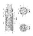
- FIG. 1Billustrates a cross-sectional view of growing rod or non-fusion scoliosis expandable spinal rod of FIG. 1A ;
- FIGS. 2A and 2Billustrate exploded views of the growing rod or non-fusion scoliosis expandable spinal rod of FIGS. 1A and 1B ;
- FIGS. 3A and 3Billustrate an exploded view and cross-sectional view, respectively, of a magnet assembly
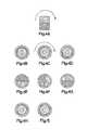
- FIGS. 4A-4Iillustrate several views of magnetic activation of a magnet of the growing rod of FIGS. 1A and 1B ;
- FIGS. 5A and 5Billustrate a perspective view and exploded view, respectively, of a first stage planetary gearset
- FIGS. 6A and 6Billustrate a perspective view and exploded view, respectively, of a second stage planetary gearset
- FIGS. 7A, 7B and 7Cillustrate additional details of the growing rod of FIGS. 1A and 1B ;
- FIGS. 8A, 8B and 8Cillustrate several views of lengthening of the growing rod of FIGS. 1A and 1B .
- a growing rod 100in accordance with implementations of the present disclosure includes a first rod 102 , an outer housing 106 , an inner housing 108 , and a second rod 104 .
- a magnet assembly 300 and a gear reduction mechanism 124are disposed within the inner housing 108 .
- rotation of the magnet assembly 300drives the gear reduction mechanism 124 , which drives a threaded driver 214 within the outer housing.
- the rotation of the threaded driver 214causes the inner housing to move along a longitudinal axis with respect to the outer housing, thus extending (or retracting the growing rod).
- the magnet assembly 300includes a magnet cover 302 , a magnet 110 , a cover lid 304 and a gear wheel 306 .
- the magnet 110includes a pair of opposing flats 308 that receive the cover lid 304 during assembly.
- the magnet 110may be made out of Neodym and may optionally include a protective epoxy layer.
- the protective layermay also be made from gold or silver and have a copper or nickel under layer.
- the magnet 110may be press fit within the magnet cover 302 and the cover lid 304 may be press fit to be received by the flats 308 to enclose the magnet cover 302 .
- the cover lid 304may be welded to the magnet cover 302 to seal the magnet assembly 300 .
- the magnet assembly 300may be sealed in such a manner in order to prevent any materials or liquid from contacting the magnet 110 and to provide for bio-compatibility.
- the cover lid 304forms a keyed slot 310 into which complementary-shaped shaft portion 312 of the gear wheel 306 is received to form the complete magnet assembly 300 .
- the magnet 110can be in any shape (e.g. round, square, hexagonal, octagonal etc.) so long as it fits within the magnet cover 302 .
- the magnet 110can be formed having a hollowed center with diametric poles, can be massive with diametric poles, can have multiple diametrical poles, etc. As shown, by applying a magnetic field from an external magnet, the magnet 110 will be urged to rotate in a predetermined direction.
- the gear reduction mechanism 124is provided within the inner housing 108 .
- the gear reduction mechanism 124includes at least a two stage assembly of planetary gearsets. It is noted that other gear arrangements may be used, and planetary gearsets are shown as an exemplary implementation.
- a first stage 204 A/ 204 Bis shown in FIGS. 2B, 5A and 5B .
- the first stage 204 A/ 204 Bincludes a carrier 504 that receives, e.g., four (or other number) planet gears 502 that each rotate on a mount 500 that is press fit into the carrier 504 .
- a sun gear 506having a slotted shaft 510 , is received within a complementary slotted recess 508 formed in face the carrier.
- the first stage 204 A/ 204 Bmay be used as an input to the gear reduction mechanism 124 .
- more than one first stage 204 A/ 204 Bmay be included in the gear reduction mechanism 124 to achieve a desire reduction.
- the first stageis designed such that a plurality of first stages may be connected in series. In such an arrangement, as shown in FIG. 7B , the planet gears of a subsequent first stage is driven by the sun gear of a preceding first stage.
- a second stage 206includes a carrier 604 that receives, e.g., four (or other number) planet 602 gears that each rotate on a mount 600 that is press fit into the carrier 604 .
- the number of gears in the second stage 206is the same as the number provided in the first stage 204 A/ 204 B.
- the face of the carrier 604 in the second stage 206includes a catch 612 .
- the catch 612has a round base 606 , a midsection 608 having hexagonal cross-section and a circular upper section 610 separated from the midsection 608 by an annular recess 614 .
- the second stage 206may be used as an output of the gear reduction mechanism 124 .
- the assembled gear reduction mechanism 124may include, e.g., three stages. However, any number of sections may be provided in order to achieve a desired input reduction. For example, each stage may provide a 4 ⁇ gear reduction. As such, the total reduction may be determined in accordance with the number of stages provided in the gear reduction mechanism 124 .
- the gear ratiosmay be changed according to the following relationship in Table 1:
- gear reduction mechanism 124may be configured such that 128 turns of gear reduction mechanism 124 extends or retracts the growing rod 100 by 1 mm. Other ratios may be used to control the rate at which the gear reduction mechanism 124 drives the growing rod 100 .
- sizes of the gears within the stagesmay be different. For example, the stages closer to the input may be smaller, where the gears near the output are relatively larger.
- an inner bearing 201is placed within the interior space of the inner housing 108 .
- the magnet assembly 300is then pressed into the inner housing 108 such that a far end of the magnet assembly 300 is received within the inner bearing 201 .
- An outer bearing 202is then placed in the inner housing 108 such that it is received by the cover lid 304 of the magnet assembly 300 .
- the first stage(s) 204 A/ 204 Bare inserted such that an inner first stage receives the gear wheel 306 of the magnet assembly 300 .
- the gear wheel 306 of the magnet assembly 300is a rotational input to drive the gear reduction mechanism 124 .
- one or more first stagesmay be placed into the inner housing 108 as part of the gear reduction mechanism 124 , followed by a second stage 206 as an output.
- the assembly of the inner housing 108is completed by placing a bearing shoulder 208 into the inner housing 108 that is, e.g., secured to the drive housing by pins 210 . As shown, four pins may be used to secure the bearing shoulder 208 to the inner housing 108 , but other numbers of pins may be used.
- the catch 612 of the second stage 206protrudes through the bearing shoulder 208 . As a result, the magnet assembly 300 and gear reduction mechanism 124 are able to rotate freely within the inner housing 108 .
- a bearing 212is slide fit around the outer circumference of the inner housing 108 at a far end.
- An inner surface of bearing 212mates with a ribbed outer surface of the inner housing 108 to prevent rotation of the bearing 212 around the circumference of the inner housing 108 .
- a threaded driver 214 having a hexagonally-shaped center holeis received and mounted to the catch 612 and secured thereto by a snap-fit locking clip 216 .
- An insert 218is placed within the outer housing 106 to act as a stop.
- the outer housing 106is placed over the inner housing 108 and rotated to threadedly retract the inner housing 108 into the outer housing 106 by cooperation of an inner threaded surface of the outer housing 108 and the threaded driver 214 .
- the inner housing 108is retracted into the outer housing 106 until reaching the insert 218 .
- flats 213 provided in the bearing 212snap fit to an inner surface of the outer housing 106 to complete the assembly.
- Four flatsmay be provided with the bearing 212 .
- the flatsserve to secure the far end of the outer housing 106 to the inner housing 108 and to counteract the moment produced by the inner housing 108 as it rotates.
- the flats 213prevent the inner housing 108 from spinning freely within the outer housing 106 .
- the first rod 102is secured to the inner housing 108 by the threaded pins 222 A/ 222 B that engage a circumferential recess 116 .
- a rounded end 118 of the first rod 102has at least one flat surface that is received by a complementary flat surface within the inner housing 108 to prevent rotation of the first rod 102 with respect to the inner housing 108 .
- the threaded pins 222 A/ 222 Bare inserted into threaded holes 220 of the inner housing 108 from the inside of the inner housing 108 .
- Each threaded pin 222 A or 222 Bincludes a locking surface that engages a ledge of a respective threaded hole 220 to prevent the threaded pin from falling out of the inner housing 108 .
- the threaded pins 222 A/ 222 Bmay be screwed from the outside using an appropriate tool to secure the first rod 102 within the inner housing 108 .
- the second rod 104is secured to the outer housing 106 by the threaded pins 226 A/ 226 B that engage a circumferential recess 120 .
- a rounded end 122 of the second rod 104has at least one flat surface that is received by a complementary flat surface within the outer housing 106 to prevent rotation of the second rod 104 with respect to the outer housing 106 .
- the threaded pins 226 A/ 226 B used in the outer housing 106may be inserted into the threaded 224 holes from the inside.
- Each threaded pin 226 A or 226 Bmay include a locking surface that engages a ledge of a respective threaded hole to prevent the threaded pin from falling out of the outer housing 106 .
- the treaded pins 226 A/ 226 Bmay be screwed from the outside using an appropriate tool to secure the second rod 104 within the outer housing 106 .
- the growing rod and its componentsmay be constructed of titanium or titanium alloys but are not so limited and may be constructed of cobalt chromium material, polymeric materials or nearly any bio-compatible material. Such materials should be relatively strong and stiff, able to take on the general size of the growing rod and its components and able to withstand normal operating conditions of the growing rod.
- the bearings and the insertmay be constructed of a Polyether ether ketone (PEEK) material that is biocompatible and has a relatively low coefficient friction.
- PEEKPolyether ether ketone
- the bearingsare not limited to constructions utilizing PEEK materials and may be constructed of nearly any material that permits the associated parts to rotate (e.g., ball bearings).
- the outer housing 106 and the inner housing 108may be made from any material that does not exhibit magnetic properties, in order to allow the magnetic field of the external magnet to pass there through to affect the magnet 110 within the growing rod.
- the outer surface of the growing rod 100may be polished to substantially remove any rough surfaces to reduce the likelihood that the body will attach to the growing rod.
- a coatingmay be placed on the growing rod for a similar purpose.
- the magnet assembly 300may be replaced by an electric motor that rotationally drives the gear reduction mechanism 124 .
- an external magnetmay be used as a source of a magnetic field to cause rotation of the magnet 110 .
- the growing rodinitially have a contracted length.
- the magnet assembly 300drives the gear reduction mechanism 124 to rotate the threaded driver 214 .
- the threaded driver 214rotates, the inner housing is driven outwardly by cooperation of the threaded driver 214 and the inner threaded surface of the outer housing 106 to laterally drive the inner housing 108 with respect to the outer housing 106 .
Landscapes
- Health & Medical Sciences (AREA)
- Orthopedic Medicine & Surgery (AREA)
- Life Sciences & Earth Sciences (AREA)
- Surgery (AREA)
- Neurology (AREA)
- Nuclear Medicine, Radiotherapy & Molecular Imaging (AREA)
- Physics & Mathematics (AREA)
- Veterinary Medicine (AREA)
- Public Health (AREA)
- Engineering & Computer Science (AREA)
- Biomedical Technology (AREA)
- Heart & Thoracic Surgery (AREA)
- Medical Informatics (AREA)
- Molecular Biology (AREA)
- Animal Behavior & Ethology (AREA)
- General Health & Medical Sciences (AREA)
- Electromagnetism (AREA)
- Radiology & Medical Imaging (AREA)
- Pathology (AREA)
- Optics & Photonics (AREA)
- Biophysics (AREA)
- Surgical Instruments (AREA)
- Orthopedics, Nursing, And Contraception (AREA)
- Dynamo-Electric Clutches, Dynamo-Electric Brakes (AREA)
- Magnetic Treatment Devices (AREA)
Abstract
Description
| TABLE 1 | ||||
| Gear ratio | Modulus | Gear ratio total | Thread pitch | Turns for 1 mm |
| i | m | i3 | P | x |
| [—] | [—] | [—] | [mm] | [—] |
| 3.0 | 0.15 | 64.0 | 0.5 | 128.0 |
In accordance with the above, the
Claims (17)
Priority Applications (2)
| Application Number | Priority Date | Filing Date | Title |
|---|---|---|---|
| US15/864,163US10507042B2 (en) | 2010-11-22 | 2018-01-08 | Non-fusion scoliosis expandable spinal rod |
| US16/705,667US11660124B2 (en) | 2010-11-22 | 2019-12-06 | Non-fusion scoliosis expandable spinal rod |
Applications Claiming Priority (4)
| Application Number | Priority Date | Filing Date | Title |
|---|---|---|---|
| US41626610P | 2010-11-22 | 2010-11-22 | |
| US13/302,187US8961567B2 (en) | 2010-11-22 | 2011-11-22 | Non-fusion scoliosis expandable spinal rod |
| US14/628,720US9861390B2 (en) | 2010-11-22 | 2015-02-23 | Non-fusion scoliosis expandable spinal rod |
| US15/864,163US10507042B2 (en) | 2010-11-22 | 2018-01-08 | Non-fusion scoliosis expandable spinal rod |
Related Parent Applications (1)
| Application Number | Title | Priority Date | Filing Date |
|---|---|---|---|
| US14/628,720ContinuationUS9861390B2 (en) | 2010-11-22 | 2015-02-23 | Non-fusion scoliosis expandable spinal rod |
Related Child Applications (1)
| Application Number | Title | Priority Date | Filing Date |
|---|---|---|---|
| US16/705,667ContinuationUS11660124B2 (en) | 2010-11-22 | 2019-12-06 | Non-fusion scoliosis expandable spinal rod |
Publications (2)
| Publication Number | Publication Date |
|---|---|
| US20180221062A1 US20180221062A1 (en) | 2018-08-09 |
| US10507042B2true US10507042B2 (en) | 2019-12-17 |
Family
ID=45099213
Family Applications (4)
| Application Number | Title | Priority Date | Filing Date |
|---|---|---|---|
| US13/302,187Active2032-11-20US8961567B2 (en) | 2010-11-22 | 2011-11-22 | Non-fusion scoliosis expandable spinal rod |
| US14/628,720Active2032-01-22US9861390B2 (en) | 2010-11-22 | 2015-02-23 | Non-fusion scoliosis expandable spinal rod |
| US15/864,163Active2031-12-26US10507042B2 (en) | 2010-11-22 | 2018-01-08 | Non-fusion scoliosis expandable spinal rod |
| US16/705,667Active2033-04-16US11660124B2 (en) | 2010-11-22 | 2019-12-06 | Non-fusion scoliosis expandable spinal rod |
Family Applications Before (2)
| Application Number | Title | Priority Date | Filing Date |
|---|---|---|---|
| US13/302,187Active2032-11-20US8961567B2 (en) | 2010-11-22 | 2011-11-22 | Non-fusion scoliosis expandable spinal rod |
| US14/628,720Active2032-01-22US9861390B2 (en) | 2010-11-22 | 2015-02-23 | Non-fusion scoliosis expandable spinal rod |
Family Applications After (1)
| Application Number | Title | Priority Date | Filing Date |
|---|---|---|---|
| US16/705,667Active2033-04-16US11660124B2 (en) | 2010-11-22 | 2019-12-06 | Non-fusion scoliosis expandable spinal rod |
Country Status (6)
| Country | Link |
|---|---|
| US (4) | US8961567B2 (en) |
| EP (2) | EP2642935B1 (en) |
| JP (1) | JP6001551B2 (en) |
| CN (1) | CN103298423B (en) |
| AU (2) | AU2011331999B2 (en) |
| WO (1) | WO2012071373A1 (en) |
Families Citing this family (66)
| Publication number | Priority date | Publication date | Assignee | Title |
|---|---|---|---|---|
| US7955357B2 (en) | 2004-07-02 | 2011-06-07 | Ellipse Technologies, Inc. | Expandable rod system to treat scoliosis and method of using the same |
| EP2279700B1 (en)* | 2006-09-06 | 2018-10-03 | Covidien LP | Barbed suture with bioactive substance |
| US7862502B2 (en) | 2006-10-20 | 2011-01-04 | Ellipse Technologies, Inc. | Method and apparatus for adjusting a gastrointestinal restriction device |
| US20090112262A1 (en) | 2007-10-30 | 2009-04-30 | Scott Pool | Skeletal manipulation system |
| US11202707B2 (en) | 2008-03-25 | 2021-12-21 | Nuvasive Specialized Orthopedics, Inc. | Adjustable implant system |
| US11241257B2 (en) | 2008-10-13 | 2022-02-08 | Nuvasive Specialized Orthopedics, Inc. | Spinal distraction system |
| US8382756B2 (en) | 2008-11-10 | 2013-02-26 | Ellipse Technologies, Inc. | External adjustment device for distraction device |
| US8197490B2 (en) | 2009-02-23 | 2012-06-12 | Ellipse Technologies, Inc. | Non-invasive adjustable distraction system |
| US9622792B2 (en) | 2009-04-29 | 2017-04-18 | Nuvasive Specialized Orthopedics, Inc. | Interspinous process device and method |
| JP5751642B2 (en) | 2009-09-04 | 2015-07-22 | エリプス テクノロジーズ, インク.Ellipse Technologies, Inc. | Bone growth apparatus and method |
| US8568457B2 (en) | 2009-12-01 | 2013-10-29 | DePuy Synthes Products, LLC | Non-fusion scoliosis expandable spinal rod |
| US8777947B2 (en) | 2010-03-19 | 2014-07-15 | Smith & Nephew, Inc. | Telescoping IM nail and actuating mechanism |
| US9248043B2 (en) | 2010-06-30 | 2016-02-02 | Ellipse Technologies, Inc. | External adjustment device for distraction device |
| WO2012021378A2 (en) | 2010-08-09 | 2012-02-16 | Ellipse Technologies, Inc. | Maintenance feature in magnetic implant |
| AU2011331999B2 (en)* | 2010-11-22 | 2016-07-21 | Synthes Gmbh | Non-fusion scoliosis expandable spinal rod |
| WO2012112396A2 (en) | 2011-02-14 | 2012-08-23 | Ellipse Technologies, Inc. | Device and method for treating fractured bones |
| BR112013029376A2 (en) | 2011-05-16 | 2017-01-31 | Smith & Nephew Inc | skeleton extension measurement |
| US10743794B2 (en) | 2011-10-04 | 2020-08-18 | Nuvasive Specialized Orthopedics, Inc. | Devices and methods for non-invasive implant length sensing |
| US10016220B2 (en) | 2011-11-01 | 2018-07-10 | Nuvasive Specialized Orthopedics, Inc. | Adjustable magnetic devices and methods of using same |
| US9949761B2 (en) | 2011-12-12 | 2018-04-24 | Children's Hospital Medical Center Of Akron | Noninvasive device for adjusting fastener |
| US10016226B2 (en)* | 2011-12-12 | 2018-07-10 | Children's Hospital Medical Center Of Akron | Noninvasive device for adjusting fastener |
| US9078711B2 (en) | 2012-06-06 | 2015-07-14 | Ellipse Technologies, Inc. | Devices and methods for detection of slippage of magnetic coupling in implantable medical devices |
| US20130338714A1 (en) | 2012-06-15 | 2013-12-19 | Arvin Chang | Magnetic implants with improved anatomical compatibility |
| EP2712560B1 (en) | 2012-09-07 | 2014-12-24 | K2M, Inc. | Growing spinal rod system |
| US9044281B2 (en) | 2012-10-18 | 2015-06-02 | Ellipse Technologies, Inc. | Intramedullary implants for replacing lost bone |
| EP2911616B1 (en) | 2012-10-29 | 2020-10-07 | NuVasive Specialized Orthopedics, Inc. | Adjustable devices for treating arthritis of the knee |
| US9179938B2 (en) | 2013-03-08 | 2015-11-10 | Ellipse Technologies, Inc. | Distraction devices and method of assembling the same |
| US10226242B2 (en) | 2013-07-31 | 2019-03-12 | Nuvasive Specialized Orthopedics, Inc. | Noninvasively adjustable suture anchors |
| US9801734B1 (en) | 2013-08-09 | 2017-10-31 | Nuvasive, Inc. | Lordotic expandable interbody implant |
| CN103494636B (en)* | 2013-09-23 | 2016-08-10 | 李登宇 | A kind of can fix and orthotic device the spinal column of automatic telescopic in vivo |
| US10751094B2 (en) | 2013-10-10 | 2020-08-25 | Nuvasive Specialized Orthopedics, Inc. | Adjustable spinal implant |
| EP2915496B2 (en)* | 2014-03-06 | 2024-06-26 | MPS Micro Precision Systems AG | Implantable device |
| CN106456215B (en) | 2014-04-28 | 2020-04-10 | 诺威适骨科专科公司 | External adjustment device for adjusting a medical implant |
| US9931138B2 (en)* | 2014-10-15 | 2018-04-03 | Globus Medical, Inc. | Orthopedic extendable rods |
| KR102588501B1 (en) | 2014-10-23 | 2023-10-11 | 누베이시브 스페셜라이즈드 오소페딕스, 인크. | Remotely adjustable interactive bone reshaping implant |
| ES2908064T3 (en) | 2014-12-26 | 2022-04-27 | Nuvasive Specialized Orthopedics Inc | distraction systems |
| CA2917676A1 (en) | 2015-01-13 | 2016-07-13 | Stryker European Holdings I, Llc | Growing rods and methods of use |
| US10238427B2 (en) | 2015-02-19 | 2019-03-26 | Nuvasive Specialized Orthopedics, Inc. | Systems and methods for vertebral adjustment |
| DE102015109624A1 (en)* | 2015-06-16 | 2016-12-22 | Wittenstein Se | Mechatronic implant |
| US10226281B2 (en)* | 2015-10-05 | 2019-03-12 | Globus Medical, Inc. | Growing rod for treating spinal deformities and method for using same |
| BR112018007347A2 (en) | 2015-10-16 | 2018-10-23 | Nuvasive Specialized Orthopedics, Inc. | adjustable devices for the treatment of knee arthritis |
| CN108601611B (en) | 2015-12-10 | 2021-11-02 | 诺威适骨科专科公司 | External adjustment device for stretcher |
| BR112018015504A2 (en) | 2016-01-28 | 2018-12-18 | Nuvasive Specialized Orthopedics, Inc. | bone transport systems |
| WO2017139548A1 (en) | 2016-02-10 | 2017-08-17 | Nuvasive Specialized Orthopedics, Inc. | Systems and methods for controlling multiple surgical variables |
| EP3413820B1 (en) | 2016-02-12 | 2024-04-10 | Nuvasive, Inc. | Post-operatively adjustable spinal fixation devices |
| US10456172B2 (en) | 2016-02-12 | 2019-10-29 | Nuvasive, Inc. | Magnetically actuateable rod insertion for minimally invasive surgery |
| US12262917B2 (en) | 2016-05-19 | 2025-04-01 | Auctus Surgical, Inc. | Spinal curvature modulation systems and methods |
| CN109152596B (en) | 2016-05-19 | 2022-07-08 | 奥图斯外科手术股份有限公司 | Spinal curvature adjustment system |
| WO2017206691A1 (en)* | 2016-05-31 | 2017-12-07 | 重庆西山科技股份有限公司 | Magnet-driven medical handle |
| EP3528725B1 (en) | 2016-10-24 | 2023-09-06 | Indius Medical Technologies Pvt. Ltd. | Self-actuating growing rod systems |
| WO2018102101A2 (en) | 2016-11-09 | 2018-06-07 | Children's Hospital Medical Center Of Akron | Distraction osteogenesis system |
| US10653407B2 (en) | 2016-12-21 | 2020-05-19 | Nuvasive, Inc. | Surgical retractor |
| US11446064B2 (en) | 2018-04-26 | 2022-09-20 | Stryker European Operations Holdings Llc | Orthopedic growing devices |
| CN108703798A (en)* | 2018-08-13 | 2018-10-26 | 北京大学人民医院 | The noninvasive growing rod of contactless electromagnetic drive for scoliosis orthopedic |
| JP2022519380A (en) | 2019-02-07 | 2022-03-23 | ニューベイシブ スペシャライズド オーソペディックス,インコーポレイテッド | Ultrasonic communication in medical devices |
| US11589901B2 (en) | 2019-02-08 | 2023-02-28 | Nuvasive Specialized Orthopedics, Inc. | External adjustment device |
| US11432854B2 (en)* | 2019-03-15 | 2022-09-06 | Desird Tasarim Arge Uygulama Elektronik Destek Ithalat Ihracat Sanayi Ve Ticaret Limited Sirketi | Extension drive mechanism for intramedullary extension nails |
| CN111603232A (en)* | 2020-06-23 | 2020-09-01 | 北京理贝尔生物工程研究所有限公司 | Scoliosis Correction Device |
| NL2025981B1 (en)* | 2020-07-03 | 2022-03-11 | Osseointegration Int B V | Bone nail device |
| US12213708B2 (en) | 2020-09-08 | 2025-02-04 | Nuvasive Specialized Orthopedics, Inc. | Remote control module for adjustable implants |
| US20220265326A1 (en) | 2021-02-23 | 2022-08-25 | Nuvasive Specialized Orthopedics, Inc. | Adjustable implant, system and methods |
| US11737787B1 (en) | 2021-05-27 | 2023-08-29 | Nuvasive, Inc. | Bone elongating devices and methods of use |
| EP4380480A1 (en) | 2021-08-03 | 2024-06-12 | NuVasive Specialized Orthopedics, Inc. | Adjustable implant |
| US12426869B2 (en) | 2022-08-10 | 2025-09-30 | Indius Medical Technologies Private Limited | Constant distraction force driven self actuating growing rod systems |
| US20240341814A1 (en)* | 2023-04-13 | 2024-10-17 | University Of Cincinnati | Adjustable device for correcting scoliosis |
| US20240358418A1 (en)* | 2023-04-25 | 2024-10-31 | Nuvasive Specialized Orthopedics, Inc. | Flat plate mechanisms for bone lengthening |
Citations (114)
| Publication number | Priority date | Publication date | Assignee | Title |
|---|---|---|---|---|
| US3270792A (en) | 1964-04-20 | 1966-09-06 | Newton Insert Company | Threaded element with carrier part deforming locking key |
| US3810259A (en) | 1971-01-25 | 1974-05-14 | Fairchild Industries | Implantable urinary control apparatus |
| US3976060A (en) | 1974-04-09 | 1976-08-24 | Messerschmitt-Bolkow-Blohm Gmbh | Extension apparatus, especially for osteotomic surgery |
| US4312336A (en) | 1978-11-10 | 1982-01-26 | Orthofix S.R.1. | External axial fixation unit |
| US4453539A (en) | 1982-03-01 | 1984-06-12 | The University Of Toledo | Expandable intramedullary nail for the fixation of bone fractures |
| US4665736A (en) | 1985-05-27 | 1987-05-19 | Oriental Yeast Co., Ltd | Stirring device for automatically measuring dissolved oxygen |
| US4850821A (en) | 1987-03-13 | 1989-07-25 | Nikkiso Eiko Co., Ltd. | Multiple magnet drive pump |
| US4921499A (en) | 1987-10-05 | 1990-05-01 | Ordev B.V. | Adjustable prosthesis |
| US4926708A (en) | 1987-11-17 | 1990-05-22 | Deutsch Forschungsanstalt Fur Luft- Und Raumfahrt E.V. | Apparatus for converting rotary motion into axial motion |
| US4946459A (en) | 1989-12-04 | 1990-08-07 | Georgia Tech Research Corporation | Intramedullary device |
| US4979672A (en) | 1989-06-21 | 1990-12-25 | Johnson Service Company | Shape memory actuator |
| US5013949A (en) | 1990-06-25 | 1991-05-07 | Sundstrand Corporation | Magnetic transmission |
| US5035712A (en) | 1989-06-16 | 1991-07-30 | Ordev B.V. | Self-adjusting prosthesis attachment |
| US5074882A (en) | 1988-06-09 | 1991-12-24 | Medinov Sarl | Progressive elongation centro-medullar nail |
| US5120135A (en) | 1989-12-13 | 1992-06-09 | Syntex (U.S.A.) Inc. | Method and apparatus for keeping particles in suspension |
| US5150770A (en) | 1991-01-25 | 1992-09-29 | Contraves Italiana S.P.A. | Recharge device, particularly for drive mechanisms for extending and withdrawing operative members of a space vehicle |
| US5263955A (en) | 1989-07-04 | 1993-11-23 | Rainer Baumgart | Medullary nail |
| US5356411A (en) | 1993-02-18 | 1994-10-18 | Spievack Alan R | Bone transporter |
| US5364396A (en) | 1993-03-29 | 1994-11-15 | Robinson Randolph C | Distraction method and apparatus |
| US5415660A (en) | 1994-01-07 | 1995-05-16 | Regents Of The University Of Minnesota | Implantable limb lengthening nail driven by a shape memory alloy |
| US5505733A (en) | 1993-10-22 | 1996-04-09 | Justin; Daniel F. | Intramedullary skeletal distractor and method |
| US5536269A (en) | 1993-02-18 | 1996-07-16 | Genesis Orthopedics | Bone and tissue lengthening device |
| US5551871A (en) | 1993-03-05 | 1996-09-03 | Besselink; Petrus A. | Temperature-sensitive medical/dental apparatus |
| US5569967A (en) | 1991-09-11 | 1996-10-29 | Temper Corporation | Magnetic gear and gear train configuration |
| US5575790A (en) | 1995-03-28 | 1996-11-19 | Rensselaer Polytechnic Institute | Shape memory alloy internal linear actuator for use in orthopedic correction |
| US5626581A (en) | 1995-11-27 | 1997-05-06 | Volunteers For Medical Engineering | Implantable bone lengthening apparatus |
| US5626579A (en) | 1993-02-12 | 1997-05-06 | The Cleveland Clinic Foundation | Bone transport and lengthening system |
| US5672177A (en) | 1996-01-31 | 1997-09-30 | The General Hospital Corporation | Implantable bone distraction device |
| US5700263A (en) | 1996-06-17 | 1997-12-23 | Schendel; Stephen A. | Bone distraction apparatus |
| US5704939A (en) | 1996-04-09 | 1998-01-06 | Justin; Daniel F. | Intramedullary skeletal distractor and method |
| US5720746A (en) | 1994-11-16 | 1998-02-24 | Soubeiran; Arnaud Andre | Device for displacing two bodies relative to each other |
| US5762599A (en) | 1994-05-02 | 1998-06-09 | Influence Medical Technologies, Ltd. | Magnetically-coupled implantable medical devices |
| US5827286A (en) | 1997-02-14 | 1998-10-27 | Incavo; Stephen J. | Incrementally adjustable tibial osteotomy fixation device and method |
| US5961553A (en) | 1995-02-13 | 1999-10-05 | Medinov-Amp | Long bone elongation device |
| WO1999051160A1 (en) | 1998-04-02 | 1999-10-14 | The University Of Birmingham | Distraction device |
| US6033412A (en) | 1997-04-03 | 2000-03-07 | Losken; H. Wolfgang | Automated implantable bone distractor for incremental bone adjustment |
| US6036690A (en) | 1995-04-11 | 2000-03-14 | De La Plaza Fernandez; Rafael | Linear expander for the progressive correction of craniofacial deformations |
| WO2000033752A1 (en) | 1998-12-04 | 2000-06-15 | Wittenstein Gmbh & Co. Kg | Distraction device |
| US6187004B1 (en) | 1993-07-14 | 2001-02-13 | Jeffrey A. Fearon | Subcutaneous bone expansion device |
| US6245075B1 (en) | 1997-01-07 | 2001-06-12 | Wittenstein Motion Control Gmbh | Distraction device for moving apart two bone sections |
| US6277124B1 (en) | 1999-10-27 | 2001-08-21 | Synthes (Usa) | Method and apparatus for ratcheting adjustment of bone segments |
| US6326707B1 (en) | 2000-05-08 | 2001-12-04 | Mark A. Gummin | Shape memory alloy actuator |
| US6336929B1 (en) | 1998-01-05 | 2002-01-08 | Orthodyne, Inc. | Intramedullary skeletal distractor and method |
| US6358255B1 (en) | 2000-03-06 | 2002-03-19 | Micerium S.R.L. | Distraction osteogenesis device and method |
| US6375638B2 (en) | 1999-02-12 | 2002-04-23 | Medtronic Minimed, Inc. | Incremental motion pump mechanisms powered by shape memory alloy wire or the like |
| US6383185B1 (en) | 1999-03-01 | 2002-05-07 | Rainer Baumgart | Medullary nail for the distraction of bones |
| US20030032958A1 (en) | 2000-02-29 | 2003-02-13 | Soubeiran Andre Arnaud | Device for relative displacement of two bodies |
| US6565576B1 (en) | 1998-12-04 | 2003-05-20 | Wittenstein Gmbh & Co. Kg | Distraction assembly |
| CN1433286A (en) | 2000-04-13 | 2003-07-30 | 伦敦大学学院 | Surgical Bone Separation Device |
| US6616672B1 (en) | 1999-07-24 | 2003-09-09 | Holger K. Essiger | Surgical instrument for displacing bone parts |
| US6673079B1 (en) | 1999-08-16 | 2004-01-06 | Washington University | Device for lengthening and reshaping bone by distraction osteogenesis |
| US6684724B2 (en) | 2000-02-17 | 2004-02-03 | Indian Space Research Organization | Shape memory alloy step drive mechanism for providing step motion to a system |
| US6684904B2 (en) | 1999-06-15 | 2004-02-03 | Seiko Instruments Inc. | Variable pressure valve apparatus |
| US6706042B2 (en) | 2001-03-16 | 2004-03-16 | Finsbury (Development) Limited | Tissue distractor |
| US20040059331A1 (en) | 2002-09-17 | 2004-03-25 | Visionmed, L.L.C. | Unilateral fixator |
| US6716218B2 (en) | 2001-02-28 | 2004-04-06 | Hol-Med Corporation | Instrument for bone distraction and compression having ratcheting tips |
| US6730087B1 (en) | 1998-07-02 | 2004-05-04 | Michael Butsch | Bone distraction device |
| US6769830B1 (en) | 2000-07-05 | 2004-08-03 | Lockheed Martin Corporation | Connector assembly |
| US6783530B1 (en) | 1999-10-22 | 2004-08-31 | Expanding Orthopedics Inc. | Expandable orthopedic device |
| US20040193266A1 (en) | 2003-03-31 | 2004-09-30 | Meyer Rudolf Xaver | Expansible prosthesis and magnetic apparatus |
| US6832477B2 (en) | 2000-05-08 | 2004-12-21 | Mark A Gummin | Shape memory alloy actuator |
| US6835207B2 (en) | 1996-07-22 | 2004-12-28 | Fred Zacouto | Skeletal implant |
| US6852113B2 (en) | 2001-12-14 | 2005-02-08 | Orthopaedic Designs, Llc | Internal osteotomy fixation device |
| US6860691B2 (en) | 2001-06-18 | 2005-03-01 | John Duncan Unsworth | Self adjusting, high strength, screw system |
| US6918910B2 (en) | 2002-12-16 | 2005-07-19 | John T. Smith | Implantable distraction device |
| US6918980B2 (en) | 2001-05-31 | 2005-07-19 | Bfs Diversified Products, Llc | Turn-up device for making a molded body of an air spring for a vehicle wheel suspension or a lift axle |
| US20050234448A1 (en) | 2004-03-19 | 2005-10-20 | Mccarthy James | Implantable bone-lengthening device |
| US20050246034A1 (en) | 2002-08-30 | 2005-11-03 | Arnaud Soubeiran | Implantable mechanical device with adjustable geometry |
| US20050261779A1 (en) | 2003-11-17 | 2005-11-24 | Meyer Rudolf X | Expansible rod-type prosthesis and external magnetic apparatus |
| US20060009767A1 (en) | 2004-07-02 | 2006-01-12 | Kiester P D | Expandable rod system to treat scoliosis and method of using the same |
| US20060047282A1 (en) | 2004-08-30 | 2006-03-02 | Vermillion Technologies, Llc | Implant for correction of spinal deformity |
| US20060074448A1 (en) | 2004-09-29 | 2006-04-06 | The Regents Of The University Of California | Apparatus and methods for magnetic alteration of deformities |
| US20060079897A1 (en) | 2004-09-29 | 2006-04-13 | Harrison Michael R | Apparatus and methods for magnetic alteration of anatomical features |
| US7063706B2 (en) | 2001-11-19 | 2006-06-20 | Wittenstein Ag | Distraction device |
| US7135022B2 (en) | 2001-05-23 | 2006-11-14 | Orthogon 2003 Ltd. | Magnetically-actuable intramedullary device |
| US20060271107A1 (en) | 2004-09-29 | 2006-11-30 | Harrison Michael R | Apparatus and methods for magnetic alteration of anatomical features |
| US20070010814A1 (en) | 2003-08-28 | 2007-01-11 | Roman Stauch | Device for extending bones |
| US20070015622A1 (en) | 2003-08-28 | 2007-01-18 | Roman Stauch | Planetary roll system, in particular for a device for extending bones |
| US20070073098A1 (en) | 2005-09-23 | 2007-03-29 | Ellipse Technologies, Inc. | Method and apparatus for adjusting body lumens |
| US7240677B2 (en) | 2003-02-03 | 2007-07-10 | Biomedical Enterprises, Inc. | System and method for force, displacement, and rate control of shaped memory material implants |
| US20070185374A1 (en) | 2006-01-17 | 2007-08-09 | Ellipse Technologies, Inc. | Two-way adjustable implant |
| US20070265646A1 (en) | 2006-01-17 | 2007-11-15 | Ellipse Technologies, Inc. | Dynamically adjustable gastric implants |
| US7297146B2 (en) | 2004-01-30 | 2007-11-20 | Warsaw Orthopedic, Inc. | Orthopedic distraction implants and techniques |
| US20070270803A1 (en) | 2006-04-06 | 2007-11-22 | Lukas Giger | Remotely Adjustable Tissue Displacement Device |
| US20070276378A1 (en) | 2004-09-29 | 2007-11-29 | The Regents Of The University Of California | Apparatus and methods for magnetic alteration of anatomical features |
| FR2906453A1 (en) | 2006-10-03 | 2008-04-04 | Arnaud Andre Soubeiran | Intra body e.g. bone, extending device e.g. oesto implant, for use by surgeon, has connection unit for connecting between permanent magnet and part, and screw and thread rotating output shaft to drive movement of another part |
| US20080097249A1 (en) | 2006-10-20 | 2008-04-24 | Ellipse Technologies, Inc. | External sensing system for gastric restriction devices |
| US20080097487A1 (en) | 2006-10-20 | 2008-04-24 | Scott Pool | Method and apparatus for adjusting a gastrointestinal restriction device |
| US20080097496A1 (en) | 2006-10-20 | 2008-04-24 | Arvin Chang | System and method for securing an implantable interface to a mammal |
| US20080108995A1 (en) | 2006-11-06 | 2008-05-08 | Janet Conway | Internal bone transport |
| US20080172072A1 (en) | 2007-01-11 | 2008-07-17 | Ellipse Technologies, Inc. | Internal sensors for use with gastric restriction devices |
| US20090112263A1 (en) | 2007-10-30 | 2009-04-30 | Scott Pool | Skeletal manipulation system |
| WO2009115645A1 (en) | 2008-03-19 | 2009-09-24 | Helsinki University Of Technology | Internal osteodistraction device |
| US20090254088A1 (en) | 2006-06-13 | 2009-10-08 | Arnaud Soubeiran | Device for intrabody extension with screws working in traction |
| US20100094306A1 (en) | 2008-10-13 | 2010-04-15 | Arvin Chang | Spinal distraction system |
| US20100114103A1 (en) | 2008-11-06 | 2010-05-06 | The Regents Of The University Of California | Apparatus and methods for alteration of anatomical features |
| US20100121323A1 (en) | 2008-11-10 | 2010-05-13 | Ellipse Technologies, Inc. | External adjustment device for distraction device |
| WO2010052465A1 (en) | 2008-11-05 | 2010-05-14 | Dalmatic Lystrup A/S | Bone fixation system |
| US7753915B1 (en) | 2007-06-14 | 2010-07-13 | August Eksler | Bi-directional bone length adjustment system |
| US20100217271A1 (en) | 2009-02-23 | 2010-08-26 | Ellipse Technologies, Inc. | Spinal distraction system |
| US20100280519A1 (en) | 2007-05-28 | 2010-11-04 | Arnaud Soubeiran | Implantable distractor whose length can be modified without reoperation and which has a j-shape |
| US20100280551A1 (en) | 2009-04-29 | 2010-11-04 | Ellipse Technologies, Inc. | Interspinous process device and method |
| US20110060336A1 (en) | 2009-09-04 | 2011-03-10 | Ellipse Technologies, Inc. | Bone growth device and method |
| US20110238126A1 (en) | 2010-03-23 | 2011-09-29 | Arnaud Soubeiran | Device for the displacement of tissues, especially bone tissues |
| US8043299B2 (en) | 2006-11-06 | 2011-10-25 | Janet Conway | Internal bone transport |
| US20120004494A1 (en) | 2010-06-30 | 2012-01-05 | Timothy John Payne | External adjustment device for distraction device |
| US20120035661A1 (en) | 2010-08-09 | 2012-02-09 | Ellipse Technologies, Inc. | Maintenance feature in magnetic implant |
| US20120035656A1 (en) | 2010-08-09 | 2012-02-09 | Ellipse Technologies, Inc. | External maintenance feature for magnetic implant |
| US8142454B2 (en) | 2004-09-29 | 2012-03-27 | The Regents Of The University Of California, San Francisco | Apparatus and method for magnetic alteration of anatomical features |
| US20120179215A1 (en) | 2009-09-09 | 2012-07-12 | Arnaud Soubeiran | Intracorporeal device for moving tissue |
| US8525063B2 (en) | 2009-07-01 | 2013-09-03 | Sodick Co., Ltd. | Wire electric discharge machining apparatus |
| US8568457B2 (en) | 2009-12-01 | 2013-10-29 | DePuy Synthes Products, LLC | Non-fusion scoliosis expandable spinal rod |
| US8961567B2 (en)* | 2010-11-22 | 2015-02-24 | DePuy Synthes Products, LLC | Non-fusion scoliosis expandable spinal rod |
| US9931138B2 (en) | 2014-10-15 | 2018-04-03 | Globus Medical, Inc. | Orthopedic extendable rods |
- 2011
- 2011-11-22AUAU2011331999Apatent/AU2011331999B2/enactiveActive
- 2011-11-22JPJP2013541009Apatent/JP6001551B2/enactiveActive
- 2011-11-22CNCN201180063949.0Apatent/CN103298423B/enactiveActive
- 2011-11-22WOPCT/US2011/061767patent/WO2012071373A1/enactiveApplication Filing
- 2011-11-22EPEP11791718.7Apatent/EP2642935B1/enactiveActive
- 2011-11-22EPEP16163309.4Apatent/EP3069675B1/enactiveActive
- 2011-11-22USUS13/302,187patent/US8961567B2/enactiveActive
- 2015
- 2015-02-23USUS14/628,720patent/US9861390B2/enactiveActive
- 2016
- 2016-07-08AUAU2016204746Apatent/AU2016204746A1/ennot_activeAbandoned
- 2018
- 2018-01-08USUS15/864,163patent/US10507042B2/enactiveActive
- 2019
- 2019-12-06USUS16/705,667patent/US11660124B2/enactiveActive
Patent Citations (152)
| Publication number | Priority date | Publication date | Assignee | Title |
|---|---|---|---|---|
| US3270792A (en) | 1964-04-20 | 1966-09-06 | Newton Insert Company | Threaded element with carrier part deforming locking key |
| US3810259A (en) | 1971-01-25 | 1974-05-14 | Fairchild Industries | Implantable urinary control apparatus |
| US3976060A (en) | 1974-04-09 | 1976-08-24 | Messerschmitt-Bolkow-Blohm Gmbh | Extension apparatus, especially for osteotomic surgery |
| US4312336A (en) | 1978-11-10 | 1982-01-26 | Orthofix S.R.1. | External axial fixation unit |
| US4453539A (en) | 1982-03-01 | 1984-06-12 | The University Of Toledo | Expandable intramedullary nail for the fixation of bone fractures |
| US4665736A (en) | 1985-05-27 | 1987-05-19 | Oriental Yeast Co., Ltd | Stirring device for automatically measuring dissolved oxygen |
| US4850821A (en) | 1987-03-13 | 1989-07-25 | Nikkiso Eiko Co., Ltd. | Multiple magnet drive pump |
| US4921499A (en) | 1987-10-05 | 1990-05-01 | Ordev B.V. | Adjustable prosthesis |
| US4926708A (en) | 1987-11-17 | 1990-05-22 | Deutsch Forschungsanstalt Fur Luft- Und Raumfahrt E.V. | Apparatus for converting rotary motion into axial motion |
| US5074882A (en) | 1988-06-09 | 1991-12-24 | Medinov Sarl | Progressive elongation centro-medullar nail |
| US5035712A (en) | 1989-06-16 | 1991-07-30 | Ordev B.V. | Self-adjusting prosthesis attachment |
| US4979672A (en) | 1989-06-21 | 1990-12-25 | Johnson Service Company | Shape memory actuator |
| US5263955A (en) | 1989-07-04 | 1993-11-23 | Rainer Baumgart | Medullary nail |
| US4946459A (en) | 1989-12-04 | 1990-08-07 | Georgia Tech Research Corporation | Intramedullary device |
| US5120135A (en) | 1989-12-13 | 1992-06-09 | Syntex (U.S.A.) Inc. | Method and apparatus for keeping particles in suspension |
| US5013949A (en) | 1990-06-25 | 1991-05-07 | Sundstrand Corporation | Magnetic transmission |
| US5150770A (en) | 1991-01-25 | 1992-09-29 | Contraves Italiana S.P.A. | Recharge device, particularly for drive mechanisms for extending and withdrawing operative members of a space vehicle |
| US5569967A (en) | 1991-09-11 | 1996-10-29 | Temper Corporation | Magnetic gear and gear train configuration |
| US5626579A (en) | 1993-02-12 | 1997-05-06 | The Cleveland Clinic Foundation | Bone transport and lengthening system |
| US5536269A (en) | 1993-02-18 | 1996-07-16 | Genesis Orthopedics | Bone and tissue lengthening device |
| US5356411A (en) | 1993-02-18 | 1994-10-18 | Spievack Alan R | Bone transporter |
| US5551871A (en) | 1993-03-05 | 1996-09-03 | Besselink; Petrus A. | Temperature-sensitive medical/dental apparatus |
| US5766004A (en) | 1993-03-05 | 1998-06-16 | Sofamor Danek Holdings, Inc. | Temperature sensitive medical dental apparatus |
| US5364396A (en) | 1993-03-29 | 1994-11-15 | Robinson Randolph C | Distraction method and apparatus |
| US6187004B1 (en) | 1993-07-14 | 2001-02-13 | Jeffrey A. Fearon | Subcutaneous bone expansion device |
| US5505733A (en) | 1993-10-22 | 1996-04-09 | Justin; Daniel F. | Intramedullary skeletal distractor and method |
| US5415660A (en) | 1994-01-07 | 1995-05-16 | Regents Of The University Of Minnesota | Implantable limb lengthening nail driven by a shape memory alloy |
| US6417750B1 (en) | 1994-05-02 | 2002-07-09 | Srs Medical Systems, Inc. | Magnetically-coupled implantable medical devices |
| US5762599A (en) | 1994-05-02 | 1998-06-09 | Influence Medical Technologies, Ltd. | Magnetically-coupled implantable medical devices |
| US5720746A (en) | 1994-11-16 | 1998-02-24 | Soubeiran; Arnaud Andre | Device for displacing two bodies relative to each other |
| US5961553A (en) | 1995-02-13 | 1999-10-05 | Medinov-Amp | Long bone elongation device |
| US5575790A (en) | 1995-03-28 | 1996-11-19 | Rensselaer Polytechnic Institute | Shape memory alloy internal linear actuator for use in orthopedic correction |
| US6036690A (en) | 1995-04-11 | 2000-03-14 | De La Plaza Fernandez; Rafael | Linear expander for the progressive correction of craniofacial deformations |
| US5626581A (en) | 1995-11-27 | 1997-05-06 | Volunteers For Medical Engineering | Implantable bone lengthening apparatus |
| US5672177A (en) | 1996-01-31 | 1997-09-30 | The General Hospital Corporation | Implantable bone distraction device |
| WO1999034746A1 (en) | 1996-04-09 | 1999-07-15 | Orthodyne, Inc. | Intramedullary skeletal distractor and method |
| US5704939A (en) | 1996-04-09 | 1998-01-06 | Justin; Daniel F. | Intramedullary skeletal distractor and method |
| US5700263A (en) | 1996-06-17 | 1997-12-23 | Schendel; Stephen A. | Bone distraction apparatus |
| US6835207B2 (en) | 1996-07-22 | 2004-12-28 | Fred Zacouto | Skeletal implant |
| US6245075B1 (en) | 1997-01-07 | 2001-06-12 | Wittenstein Motion Control Gmbh | Distraction device for moving apart two bone sections |
| US5827286A (en) | 1997-02-14 | 1998-10-27 | Incavo; Stephen J. | Incrementally adjustable tibial osteotomy fixation device and method |
| US6033412A (en) | 1997-04-03 | 2000-03-07 | Losken; H. Wolfgang | Automated implantable bone distractor for incremental bone adjustment |
| US6336929B1 (en) | 1998-01-05 | 2002-01-08 | Orthodyne, Inc. | Intramedullary skeletal distractor and method |
| WO1999051160A1 (en) | 1998-04-02 | 1999-10-14 | The University Of Birmingham | Distraction device |
| US6730087B1 (en) | 1998-07-02 | 2004-05-04 | Michael Butsch | Bone distraction device |
| WO2000033752A1 (en) | 1998-12-04 | 2000-06-15 | Wittenstein Gmbh & Co. Kg | Distraction device |
| US6565576B1 (en) | 1998-12-04 | 2003-05-20 | Wittenstein Gmbh & Co. Kg | Distraction assembly |
| US6375638B2 (en) | 1999-02-12 | 2002-04-23 | Medtronic Minimed, Inc. | Incremental motion pump mechanisms powered by shape memory alloy wire or the like |
| US6383185B1 (en) | 1999-03-01 | 2002-05-07 | Rainer Baumgart | Medullary nail for the distraction of bones |
| US6684904B2 (en) | 1999-06-15 | 2004-02-03 | Seiko Instruments Inc. | Variable pressure valve apparatus |
| US6616672B1 (en) | 1999-07-24 | 2003-09-09 | Holger K. Essiger | Surgical instrument for displacing bone parts |
| US6673079B1 (en) | 1999-08-16 | 2004-01-06 | Washington University | Device for lengthening and reshaping bone by distraction osteogenesis |
| US6783530B1 (en) | 1999-10-22 | 2004-08-31 | Expanding Orthopedics Inc. | Expandable orthopedic device |
| US6277124B1 (en) | 1999-10-27 | 2001-08-21 | Synthes (Usa) | Method and apparatus for ratcheting adjustment of bone segments |
| US6684724B2 (en) | 2000-02-17 | 2004-02-03 | Indian Space Research Organization | Shape memory alloy step drive mechanism for providing step motion to a system |
| US6796984B2 (en) | 2000-02-29 | 2004-09-28 | Soubeiran Andre Arnaud | Device for relative displacement of two bodies |
| US20030032958A1 (en) | 2000-02-29 | 2003-02-13 | Soubeiran Andre Arnaud | Device for relative displacement of two bodies |
| US6358255B1 (en) | 2000-03-06 | 2002-03-19 | Micerium S.R.L. | Distraction osteogenesis device and method |
| CN1433286A (en) | 2000-04-13 | 2003-07-30 | 伦敦大学学院 | Surgical Bone Separation Device |
| US20040030395A1 (en) | 2000-04-13 | 2004-02-12 | Gordon Blunn | Surgical distraction device |
| US6849076B2 (en) | 2000-04-13 | 2005-02-01 | University College London | Surgical distraction device |
| US7021055B2 (en) | 2000-05-08 | 2006-04-04 | Gummin Mark A | Shape memory alloy actuator |
| US6832477B2 (en) | 2000-05-08 | 2004-12-21 | Mark A Gummin | Shape memory alloy actuator |
| US6326707B1 (en) | 2000-05-08 | 2001-12-04 | Mark A. Gummin | Shape memory alloy actuator |
| US6769830B1 (en) | 2000-07-05 | 2004-08-03 | Lockheed Martin Corporation | Connector assembly |
| US6716218B2 (en) | 2001-02-28 | 2004-04-06 | Hol-Med Corporation | Instrument for bone distraction and compression having ratcheting tips |
| US6706042B2 (en) | 2001-03-16 | 2004-03-16 | Finsbury (Development) Limited | Tissue distractor |
| US7135022B2 (en) | 2001-05-23 | 2006-11-14 | Orthogon 2003 Ltd. | Magnetically-actuable intramedullary device |
| US6918980B2 (en) | 2001-05-31 | 2005-07-19 | Bfs Diversified Products, Llc | Turn-up device for making a molded body of an air spring for a vehicle wheel suspension or a lift axle |
| US6860691B2 (en) | 2001-06-18 | 2005-03-01 | John Duncan Unsworth | Self adjusting, high strength, screw system |
| US7063706B2 (en) | 2001-11-19 | 2006-06-20 | Wittenstein Ag | Distraction device |
| US6852113B2 (en) | 2001-12-14 | 2005-02-08 | Orthopaedic Designs, Llc | Internal osteotomy fixation device |
| US20050251109A1 (en) | 2002-08-30 | 2005-11-10 | Arnaud Soubeiran | Device for locking/unlocking rotation in the organism |
| US20050246034A1 (en) | 2002-08-30 | 2005-11-03 | Arnaud Soubeiran | Implantable mechanical device with adjustable geometry |
| US7282052B2 (en) | 2002-09-17 | 2007-10-16 | Ebi, L.P. | Unilateral fixator |
| US20040059331A1 (en) | 2002-09-17 | 2004-03-25 | Visionmed, L.L.C. | Unilateral fixator |
| US20070282338A1 (en) | 2002-09-17 | 2007-12-06 | Ebi, L.P. | Unilateral fixator |
| US6918910B2 (en) | 2002-12-16 | 2005-07-19 | John T. Smith | Implantable distraction device |
| US7240677B2 (en) | 2003-02-03 | 2007-07-10 | Biomedical Enterprises, Inc. | System and method for force, displacement, and rate control of shaped memory material implants |
| US20040193266A1 (en) | 2003-03-31 | 2004-09-30 | Meyer Rudolf Xaver | Expansible prosthesis and magnetic apparatus |
| US7666184B2 (en) | 2003-08-28 | 2010-02-23 | Wittenstein Ag | Planetary roll system, in particular for a device for extending bones |
| US20070010814A1 (en) | 2003-08-28 | 2007-01-11 | Roman Stauch | Device for extending bones |
| US20070015622A1 (en) | 2003-08-28 | 2007-01-18 | Roman Stauch | Planetary roll system, in particular for a device for extending bones |
| US20050261779A1 (en) | 2003-11-17 | 2005-11-24 | Meyer Rudolf X | Expansible rod-type prosthesis and external magnetic apparatus |
| US7297146B2 (en) | 2004-01-30 | 2007-11-20 | Warsaw Orthopedic, Inc. | Orthopedic distraction implants and techniques |
| US20050234448A1 (en) | 2004-03-19 | 2005-10-20 | Mccarthy James | Implantable bone-lengthening device |
| US20060009767A1 (en) | 2004-07-02 | 2006-01-12 | Kiester P D | Expandable rod system to treat scoliosis and method of using the same |
| US20090204154A1 (en) | 2004-07-02 | 2009-08-13 | Ellipse Technologies, Inc. | expandable rod system to treat scoliosis and method of using the same |
| US7955357B2 (en) | 2004-07-02 | 2011-06-07 | Ellipse Technologies, Inc. | Expandable rod system to treat scoliosis and method of using the same |
| US8343192B2 (en) | 2004-07-02 | 2013-01-01 | Ellipse Technologies, Inc. | Expandable rod system to treat scoliosis and method of using the same |
| US20060047282A1 (en) | 2004-08-30 | 2006-03-02 | Vermillion Technologies, Llc | Implant for correction of spinal deformity |
| US7763053B2 (en) | 2004-08-30 | 2010-07-27 | Gordon Jeffrey D | Implant for correction of spinal deformity |
| US8043290B2 (en) | 2004-09-29 | 2011-10-25 | The Regents Of The University Of California, San Francisco | Apparatus and methods for magnetic alteration of deformities |
| US20060271107A1 (en) | 2004-09-29 | 2006-11-30 | Harrison Michael R | Apparatus and methods for magnetic alteration of anatomical features |
| US20060074448A1 (en) | 2004-09-29 | 2006-04-06 | The Regents Of The University Of California | Apparatus and methods for magnetic alteration of deformities |
| US20070276378A1 (en) | 2004-09-29 | 2007-11-29 | The Regents Of The University Of California | Apparatus and methods for magnetic alteration of anatomical features |
| US8142454B2 (en) | 2004-09-29 | 2012-03-27 | The Regents Of The University Of California, San Francisco | Apparatus and method for magnetic alteration of anatomical features |
| US8439915B2 (en) | 2004-09-29 | 2013-05-14 | The Regents Of The University Of California | Apparatus and methods for magnetic alteration of anatomical features |
| US20060079897A1 (en) | 2004-09-29 | 2006-04-13 | Harrison Michael R | Apparatus and methods for magnetic alteration of anatomical features |
| US20070073098A1 (en) | 2005-09-23 | 2007-03-29 | Ellipse Technologies, Inc. | Method and apparatus for adjusting body lumens |
| US20070265646A1 (en) | 2006-01-17 | 2007-11-15 | Ellipse Technologies, Inc. | Dynamically adjustable gastric implants |
| US20070185374A1 (en) | 2006-01-17 | 2007-08-09 | Ellipse Technologies, Inc. | Two-way adjustable implant |
| US20070270803A1 (en) | 2006-04-06 | 2007-11-22 | Lukas Giger | Remotely Adjustable Tissue Displacement Device |
| US8137349B2 (en) | 2006-06-13 | 2012-03-20 | Arnaud Soubeiran | Intrabody distraction device with a screw working in traction |
| US20090254088A1 (en) | 2006-06-13 | 2009-10-08 | Arnaud Soubeiran | Device for intrabody extension with screws working in traction |
| FR2906453A1 (en) | 2006-10-03 | 2008-04-04 | Arnaud Andre Soubeiran | Intra body e.g. bone, extending device e.g. oesto implant, for use by surgeon, has connection unit for connecting between permanent magnet and part, and screw and thread rotating output shaft to drive movement of another part |
| US8632548B2 (en) | 2006-10-03 | 2014-01-21 | Arnaud Soubeiran | Intracorporeal elongation device with a permanent magnet |
| US20100049204A1 (en) | 2006-10-03 | 2010-02-25 | Arnaud Soubeiran | Intracorporeal elongation device with a permanent magnet |
| US20080097188A1 (en) | 2006-10-20 | 2008-04-24 | Ellipse Technologies, Inc. | External sensing systems and methods for gastric restriction devices |
| US20080097249A1 (en) | 2006-10-20 | 2008-04-24 | Ellipse Technologies, Inc. | External sensing system for gastric restriction devices |
| US20080097487A1 (en) | 2006-10-20 | 2008-04-24 | Scott Pool | Method and apparatus for adjusting a gastrointestinal restriction device |
| US20080097496A1 (en) | 2006-10-20 | 2008-04-24 | Arvin Chang | System and method for securing an implantable interface to a mammal |
| US7862502B2 (en) | 2006-10-20 | 2011-01-04 | Ellipse Technologies, Inc. | Method and apparatus for adjusting a gastrointestinal restriction device |
| US20090062825A1 (en) | 2006-10-20 | 2009-03-05 | Scott Pool | Adjustable implant and method of use |
| US8043299B2 (en) | 2006-11-06 | 2011-10-25 | Janet Conway | Internal bone transport |
| US20080108995A1 (en) | 2006-11-06 | 2008-05-08 | Janet Conway | Internal bone transport |
| US20080172072A1 (en) | 2007-01-11 | 2008-07-17 | Ellipse Technologies, Inc. | Internal sensors for use with gastric restriction devices |
| WO2008109300A2 (en) | 2007-03-01 | 2008-09-12 | Ellipse Technologies, Inc. | Adjustable implant system |
| US20100280519A1 (en) | 2007-05-28 | 2010-11-04 | Arnaud Soubeiran | Implantable distractor whose length can be modified without reoperation and which has a j-shape |
| US7753915B1 (en) | 2007-06-14 | 2010-07-13 | August Eksler | Bi-directional bone length adjustment system |
| US8419734B2 (en) | 2007-10-30 | 2013-04-16 | Ellipse Technologies, Inc. | Skeletal manipulation method |
| US20090112207A1 (en) | 2007-10-30 | 2009-04-30 | Blair Walker | Skeletal manipulation method |
| US20090112263A1 (en) | 2007-10-30 | 2009-04-30 | Scott Pool | Skeletal manipulation system |
| US20130296859A1 (en) | 2007-10-30 | 2013-11-07 | Ellipse Technologies, Inc. | Skeletal manipulation method |
| WO2009058546A1 (en) | 2007-10-30 | 2009-05-07 | Ellipse Technologies, Inc. | Skeletal manipulation system |
| US20120157996A1 (en) | 2007-10-30 | 2012-06-21 | Ellipse Technologies, Inc. | Skeletal manipulation method |
| US8057472B2 (en) | 2007-10-30 | 2011-11-15 | Ellipse Technologies, Inc. | Skeletal manipulation method |
| US20090112262A1 (en) | 2007-10-30 | 2009-04-30 | Scott Pool | Skeletal manipulation system |
| WO2009115645A1 (en) | 2008-03-19 | 2009-09-24 | Helsinki University Of Technology | Internal osteodistraction device |
| US20100094306A1 (en) | 2008-10-13 | 2010-04-15 | Arvin Chang | Spinal distraction system |
| US20100094305A1 (en) | 2008-10-13 | 2010-04-15 | Arvin Chang | Spinal distraction system |
| US20100094303A1 (en) | 2008-10-13 | 2010-04-15 | Arvin Chang | Spinal distraction system |
| US20100094302A1 (en) | 2008-10-13 | 2010-04-15 | Scott Pool | Spinal distraction system |
| US20100094304A1 (en) | 2008-10-13 | 2010-04-15 | Scott Pool | Spinal distraction system |
| WO2010052465A1 (en) | 2008-11-05 | 2010-05-14 | Dalmatic Lystrup A/S | Bone fixation system |
| US20100114103A1 (en) | 2008-11-06 | 2010-05-06 | The Regents Of The University Of California | Apparatus and methods for alteration of anatomical features |
| US20100121323A1 (en) | 2008-11-10 | 2010-05-13 | Ellipse Technologies, Inc. | External adjustment device for distraction device |
| US8197490B2 (en) | 2009-02-23 | 2012-06-12 | Ellipse Technologies, Inc. | Non-invasive adjustable distraction system |
| US20100217271A1 (en) | 2009-02-23 | 2010-08-26 | Ellipse Technologies, Inc. | Spinal distraction system |
| US20100280551A1 (en) | 2009-04-29 | 2010-11-04 | Ellipse Technologies, Inc. | Interspinous process device and method |
| US8525063B2 (en) | 2009-07-01 | 2013-09-03 | Sodick Co., Ltd. | Wire electric discharge machining apparatus |
| US20110060336A1 (en) | 2009-09-04 | 2011-03-10 | Ellipse Technologies, Inc. | Bone growth device and method |
| US20120179215A1 (en) | 2009-09-09 | 2012-07-12 | Arnaud Soubeiran | Intracorporeal device for moving tissue |
| US8568457B2 (en) | 2009-12-01 | 2013-10-29 | DePuy Synthes Products, LLC | Non-fusion scoliosis expandable spinal rod |
| US9282997B2 (en) | 2009-12-01 | 2016-03-15 | DePuy Synthes Products, Inc. | Non-fusion scoliosis expandable spinal rod |
| US20110238126A1 (en) | 2010-03-23 | 2011-09-29 | Arnaud Soubeiran | Device for the displacement of tissues, especially bone tissues |
| US20120004494A1 (en) | 2010-06-30 | 2012-01-05 | Timothy John Payne | External adjustment device for distraction device |
| US20120035656A1 (en) | 2010-08-09 | 2012-02-09 | Ellipse Technologies, Inc. | External maintenance feature for magnetic implant |
| US20120035661A1 (en) | 2010-08-09 | 2012-02-09 | Ellipse Technologies, Inc. | Maintenance feature in magnetic implant |
| US8961567B2 (en)* | 2010-11-22 | 2015-02-24 | DePuy Synthes Products, LLC | Non-fusion scoliosis expandable spinal rod |
| US9861390B2 (en)* | 2010-11-22 | 2018-01-09 | DePuy Synthes Products, Inc. | Non-fusion scoliosis expandable spinal rod |
| US9931138B2 (en) | 2014-10-15 | 2018-04-03 | Globus Medical, Inc. | Orthopedic extendable rods |
Non-Patent Citations (24)
| Title |
|---|
| Campbell et al., "Expansion Thoracoplasty: The Surgical Technique of Opening-Wedge Thoracostomy," JBJS, vol. 85-A, pp. 409-420, Mar. 2003. |
| Campbell et al., "Growth of the Thoracic Spine in Congenital Scoliosis After Expansion Thoracoplasty," JBJS, vol. 85-A, pp. 409-420, Mar. 2003. |
| Campbell et al., "The Effect of Opening Wedge Thoracostomy on Thoracic Insufficiency Syndrome Syndrome Associated with Fused Ribs and Congenital Scoliosis," JBJS, vol. 86-A, pp. 1659-1674, Aug. 2004. |
| Campbell et al., "Thoracic Insufficiency Syndrome and Exotic Scoliosis," JBJS, vol. 89-A, Supp. 1, pp. 108-122, 2007. |
| Co-Pending U.S. Appl. No. 13/302,187, filed Nov. 22, 2011 (U.S. Pat. No. 8,961,567, issued Feb. 24, 2015). |
| Co-Pending U.S. Appl. No. 14/628,720 (parent application), filed Feb. 23, 2015 (U.S. Pat. No. 9,861,390, issued Jan. 9, 2018. |
| Cunningham et al., "Fusionless Scoliosis Surgery," Curr Opin Pediatr, Lippincott Williams & Wilkins, vol. 17, pp. 48-53, 2005. |
| Deacon et al., "Idiopathic Scoliosis in Three Dimensions: A Radiographic and Morphometric Analysis," The Journal of Bone and Joint Surgery, British Editorial Society of Bone and Joint Surgery, vol. 66-B, pp. 509-512, Aug. 1984. |
| Edeland et al., "Instrumentation for Distraction by Limited Surgery in Scoliosis Treatment," Journal of Biomedical Engineering, vol. 3, pp. 143-146, Apr. 1981. |
| Emans et al., "The Treatment of Spine and Chest Wall Deformities with Fused Ribs by Expansion Thoracostomy and Insertion of Vertical Expandable Prosthetic Titanium Rib," Spine, Lippincott Williams & Wilkins, Inc., vol. 30, No. 17S, pp. 558-568, 2005. |
| Grass et al., "Intermittent Distracting Rod for Correction of High Neurologic Risk Congenital Scoliosis," Spine, vol. 22, No. 16, pp. 1922-1927, 1997. |
| Hefti, "Idiopathic Scoliosis," Pediatric Orthopedics in Practice, Springer Berlin Heidelberg, pp. 72-94, 2007. |
| International Preliminary Report on Patentability and Written Opinion, dated Jun. 5, 2012, received in connection with corresponding International Patent Application No. PCT/US2010/058528. |
| International Preliminary Report on Patentability and Written Opinion, dated May 22, 2013, received in connection with International Patent Application No. PCT/US2011/061767. |
| International Search Report and Written Opinion, dated Mar. 1, 2012, received in connection with International Patent Application No. PCT/US2011/061767. |
| International Search Report, dated Feb. 17, 2011, received in connection with corresponding International Patent Application No. PCT/US2010/058528. |
| Keynan et al., "Radiographic Measurement Parameters in Thoracolumbar Fractures: A Systematic Review and Consensus Statement of the Spine Trauma Study Group," Spine, Lippincott Williams & Wilkins, Inc., vol. 31, No. 5, pp. E156-E163, 2006. |
| Klemme et al., "Spinal Instrumentation Without Fusion for Progressive Scoliosis in Young Children," Journal of Pediatric Orthopaedics, Lippincott-Raven Publisher, vol. 17, pp. 734-742, 1997. |
| Stokes et al., "Three-Dimensional Spinal Curvature in Idiopathic Scoliosis," Journal of Orthopaedic Research, Orthopeadic Research Society, Raven Press, NY, vol. 5, pp. 102-113, 1987. |
| Takaso et al., "New Remote-Controlled-Growing-Rod Spinal Instrumentation Possibly Applicable for Scoliosis in Young Children," Journal of Orthopedic Science, vol. 3, pp. 336-340, 1998. |
| U.S. Appl. No. 12/957,447, filed Dec. 1, 2010 (U.S. Pat. No. 8,568,457, issued Oct. 29, 2013). |
| U.S. Appl. No. 14/056,441, filed Oct. 17, 2013 (U.S. Pat. No. 9,282,997, issued Mar. 15, 2016). |
| U.S. Appl. No. 15/068,836, filed Mar. 14, 2016. |
| Wenger, "Spine Jack Operation in the Correction of Scoliotic Deformity," Archives of Surgery, vol. 83, pp. 901-910, 1961. |
Also Published As
| Publication number | Publication date |
|---|---|
| AU2016204746A1 (en) | 2016-07-28 |
| EP3069675B1 (en) | 2017-12-20 |
| JP6001551B2 (en) | 2016-10-05 |
| EP3069675A1 (en) | 2016-09-21 |
| WO2012071373A1 (en) | 2012-05-31 |
| CN103298423B (en) | 2016-10-05 |
| EP2642935A1 (en) | 2013-10-02 |
| US9861390B2 (en) | 2018-01-09 |
| US20120130428A1 (en) | 2012-05-24 |
| JP2014502864A (en) | 2014-02-06 |
| US11660124B2 (en) | 2023-05-30 |
| US20180221062A1 (en) | 2018-08-09 |
| CN103298423A (en) | 2013-09-11 |
| EP2642935B1 (en) | 2016-04-06 |
| US20200187989A1 (en) | 2020-06-18 |
| US8961567B2 (en) | 2015-02-24 |
| US20150157364A1 (en) | 2015-06-11 |
| AU2011331999A1 (en) | 2013-06-13 |
| AU2011331999B2 (en) | 2016-07-21 |
Similar Documents
| Publication | Publication Date | Title |
|---|---|---|
| US11660124B2 (en) | Non-fusion scoliosis expandable spinal rod | |
| US10548638B2 (en) | Non-fusion scoliosis expandable spinal rod | |
| US11925389B2 (en) | Spinal distraction system | |
| US20220031375A1 (en) | Skeletal manipulation method | |
| US20100094302A1 (en) | Spinal distraction system | |
| US9968377B2 (en) | Spinal rods formed from polymer and hybrid materials and growth rod distraction system including same | |
| CA2773041A1 (en) | Intracorporeal device for moving tissue | |
| US10159511B2 (en) | Adjustable external fixator | |
| KR101891194B1 (en) | Length adjustable rod for fixing the vertebra |
Legal Events
| Date | Code | Title | Description |
|---|---|---|---|
| AS | Assignment | Owner name:SYNTHES GMBH, SWITZERLAND Free format text:ASSIGNMENT OF ASSIGNORS INTEREST;ASSIGNOR:HUNZIKER, MARKUS;REEL/FRAME:044558/0119 Effective date:20120115 Owner name:SYNTHES USA, LLC, PENNSYLVANIA Free format text:ASSIGNMENT OF ASSIGNORS INTEREST;ASSIGNOR:SYNTHES GMBH;REEL/FRAME:044558/0190 Effective date:20120119 Owner name:DEPUY SPINE, LLC, MASSACHUSETTS Free format text:ASSIGNMENT OF ASSIGNORS INTEREST;ASSIGNOR:SYNTHES USA, LLC;REEL/FRAME:045018/0334 Effective date:20121230 Owner name:DEPUY SYNTHES PRODUCTS, INC., MASSACHUSETTS Free format text:CHANGE OF NAME;ASSIGNOR:DEPUY SYNTHES PRODUCTS, LLC;REEL/FRAME:045019/0426 Effective date:20141219 Owner name:DEPUY SYNTHES PRODUCTS, LLC, MASSACHUSETTS Free format text:CHANGE OF NAME;ASSIGNOR:HAND INNOVATIONS LLC;REEL/FRAME:045019/0468 Effective date:20121231 Owner name:HAND INNOVATIONS LLC, FLORIDA Free format text:ASSIGNMENT OF ASSIGNORS INTEREST;ASSIGNOR:DEPUY SPINE, LLC;REEL/FRAME:045018/0464 Effective date:20121230 | |
| FEPP | Fee payment procedure | Free format text:ENTITY STATUS SET TO UNDISCOUNTED (ORIGINAL EVENT CODE: BIG.); ENTITY STATUS OF PATENT OWNER: LARGE ENTITY | |
| STPP | Information on status: patent application and granting procedure in general | Free format text:DOCKETED NEW CASE - READY FOR EXAMINATION | |
| STPP | Information on status: patent application and granting procedure in general | Free format text:NON FINAL ACTION MAILED | |
| STPP | Information on status: patent application and granting procedure in general | Free format text:RESPONSE TO NON-FINAL OFFICE ACTION ENTERED AND FORWARDED TO EXAMINER | |
| STPP | Information on status: patent application and granting procedure in general | Free format text:NOTICE OF ALLOWANCE MAILED -- APPLICATION RECEIVED IN OFFICE OF PUBLICATIONS | |
| STPP | Information on status: patent application and granting procedure in general | Free format text:PUBLICATIONS -- ISSUE FEE PAYMENT VERIFIED | |
| STCF | Information on status: patent grant | Free format text:PATENTED CASE | |
| MAFP | Maintenance fee payment | Free format text:PAYMENT OF MAINTENANCE FEE, 4TH YEAR, LARGE ENTITY (ORIGINAL EVENT CODE: M1551); ENTITY STATUS OF PATENT OWNER: LARGE ENTITY Year of fee payment:4 |