US10506755B2 - Agricultural systems - Google Patents
Agricultural systemsDownload PDFInfo
- Publication number
- US10506755B2 US10506755B2US15/695,785US201715695785AUS10506755B2US 10506755 B2US10506755 B2US 10506755B2US 201715695785 AUS201715695785 AUS 201715695785AUS 10506755 B2US10506755 B2US 10506755B2
- Authority
- US
- United States
- Prior art keywords
- row
- soil
- hydraulic
- row unit
- pressure
- Prior art date
- Legal status (The legal status is an assumption and is not a legal conclusion. Google has not performed a legal analysis and makes no representation as to the accuracy of the status listed.)
- Active
Links
Images


Classifications
- A—HUMAN NECESSITIES
- A01—AGRICULTURE; FORESTRY; ANIMAL HUSBANDRY; HUNTING; TRAPPING; FISHING
- A01B—SOIL WORKING IN AGRICULTURE OR FORESTRY; PARTS, DETAILS, OR ACCESSORIES OF AGRICULTURAL MACHINES OR IMPLEMENTS, IN GENERAL
- A01B61/00—Devices for, or parts of, agricultural machines or implements for preventing overstrain
- A01B61/04—Devices for, or parts of, agricultural machines or implements for preventing overstrain of the connection between tools and carrier beam or frame
- A01B61/044—Devices for, or parts of, agricultural machines or implements for preventing overstrain of the connection between tools and carrier beam or frame the connection enabling a yielding pivoting movement around a substantially horizontal and transverse axis
- A01B61/046—Devices for, or parts of, agricultural machines or implements for preventing overstrain of the connection between tools and carrier beam or frame the connection enabling a yielding pivoting movement around a substantially horizontal and transverse axis the device including an energy accumulator for restoring the tool to its working position
- A01B61/048—Devices for, or parts of, agricultural machines or implements for preventing overstrain of the connection between tools and carrier beam or frame the connection enabling a yielding pivoting movement around a substantially horizontal and transverse axis the device including an energy accumulator for restoring the tool to its working position the connection or the energy accumulator being active in two opposite directions, e.g. for reversible plows
- A—HUMAN NECESSITIES
- A01—AGRICULTURE; FORESTRY; ANIMAL HUSBANDRY; HUNTING; TRAPPING; FISHING
- A01B—SOIL WORKING IN AGRICULTURE OR FORESTRY; PARTS, DETAILS, OR ACCESSORIES OF AGRICULTURAL MACHINES OR IMPLEMENTS, IN GENERAL
- A01B49/00—Combined machines
- A01B49/04—Combinations of soil-working tools with non-soil-working tools, e.g. planting tools
- A01B49/06—Combinations of soil-working tools with non-soil-working tools, e.g. planting tools for sowing or fertilising
- A—HUMAN NECESSITIES
- A01—AGRICULTURE; FORESTRY; ANIMAL HUSBANDRY; HUNTING; TRAPPING; FISHING
- A01B—SOIL WORKING IN AGRICULTURE OR FORESTRY; PARTS, DETAILS, OR ACCESSORIES OF AGRICULTURAL MACHINES OR IMPLEMENTS, IN GENERAL
- A01B61/00—Devices for, or parts of, agricultural machines or implements for preventing overstrain
- A01B61/04—Devices for, or parts of, agricultural machines or implements for preventing overstrain of the connection between tools and carrier beam or frame
- A01B61/044—Devices for, or parts of, agricultural machines or implements for preventing overstrain of the connection between tools and carrier beam or frame the connection enabling a yielding pivoting movement around a substantially horizontal and transverse axis
- A—HUMAN NECESSITIES
- A01—AGRICULTURE; FORESTRY; ANIMAL HUSBANDRY; HUNTING; TRAPPING; FISHING
- A01B—SOIL WORKING IN AGRICULTURE OR FORESTRY; PARTS, DETAILS, OR ACCESSORIES OF AGRICULTURAL MACHINES OR IMPLEMENTS, IN GENERAL
- A01B63/00—Lifting or adjusting devices or arrangements for agricultural machines or implements
- A01B63/002—Devices for adjusting or regulating the position of tools or wheels
- A01B63/008—Vertical adjustment of tools
- A—HUMAN NECESSITIES
- A01—AGRICULTURE; FORESTRY; ANIMAL HUSBANDRY; HUNTING; TRAPPING; FISHING
- A01C—PLANTING; SOWING; FERTILISING
- A01C5/00—Making or covering furrows or holes for sowing, planting or manuring
- A01C5/06—Machines for making or covering drills or furrows for sowing or planting
- A—HUMAN NECESSITIES
- A01—AGRICULTURE; FORESTRY; ANIMAL HUSBANDRY; HUNTING; TRAPPING; FISHING
- A01C—PLANTING; SOWING; FERTILISING
- A01C5/00—Making or covering furrows or holes for sowing, planting or manuring
- A01C5/06—Machines for making or covering drills or furrows for sowing or planting
- A01C5/066—Devices for covering drills or furrows
- A—HUMAN NECESSITIES
- A01—AGRICULTURE; FORESTRY; ANIMAL HUSBANDRY; HUNTING; TRAPPING; FISHING
- A01C—PLANTING; SOWING; FERTILISING
- A01C7/00—Sowing
- A01C7/20—Parts of seeders for conducting and depositing seed
- A01C7/201—Mounting of the seeding tools
- A01C7/203—Mounting of the seeding tools comprising depth regulation means
- A—HUMAN NECESSITIES
- A01—AGRICULTURE; FORESTRY; ANIMAL HUSBANDRY; HUNTING; TRAPPING; FISHING
- A01C—PLANTING; SOWING; FERTILISING
- A01C7/00—Sowing
- A01C7/20—Parts of seeders for conducting and depositing seed
- A01C7/201—Mounting of the seeding tools
- A01C7/205—Mounting of the seeding tools comprising pressure regulation means
- A—HUMAN NECESSITIES
- A01—AGRICULTURE; FORESTRY; ANIMAL HUSBANDRY; HUNTING; TRAPPING; FISHING
- A01B—SOIL WORKING IN AGRICULTURE OR FORESTRY; PARTS, DETAILS, OR ACCESSORIES OF AGRICULTURAL MACHINES OR IMPLEMENTS, IN GENERAL
- A01B63/00—Lifting or adjusting devices or arrangements for agricultural machines or implements
- A01B63/02—Lifting or adjusting devices or arrangements for agricultural machines or implements for implements mounted on tractors
- A01B63/10—Lifting or adjusting devices or arrangements for agricultural machines or implements for implements mounted on tractors operated by hydraulic or pneumatic means
- A01B63/111—Lifting or adjusting devices or arrangements for agricultural machines or implements for implements mounted on tractors operated by hydraulic or pneumatic means regulating working depth of implements
- A01B63/1115—Lifting or adjusting devices or arrangements for agricultural machines or implements for implements mounted on tractors operated by hydraulic or pneumatic means regulating working depth of implements using a mechanical ground contact sensor
- A—HUMAN NECESSITIES
- A01—AGRICULTURE; FORESTRY; ANIMAL HUSBANDRY; HUNTING; TRAPPING; FISHING
- A01C—PLANTING; SOWING; FERTILISING
- A01C7/00—Sowing
- A01C7/006—Minimum till seeding
- Y—GENERAL TAGGING OF NEW TECHNOLOGICAL DEVELOPMENTS; GENERAL TAGGING OF CROSS-SECTIONAL TECHNOLOGIES SPANNING OVER SEVERAL SECTIONS OF THE IPC; TECHNICAL SUBJECTS COVERED BY FORMER USPC CROSS-REFERENCE ART COLLECTIONS [XRACs] AND DIGESTS
- Y02—TECHNOLOGIES OR APPLICATIONS FOR MITIGATION OR ADAPTATION AGAINST CLIMATE CHANGE
- Y02P—CLIMATE CHANGE MITIGATION TECHNOLOGIES IN THE PRODUCTION OR PROCESSING OF GOODS
- Y02P60/00—Technologies relating to agriculture, livestock or agroalimentary industries
- Y02P60/20—Reduction of greenhouse gas [GHG] emissions in agriculture, e.g. CO2
- Y02P60/23—
Definitions
- the present inventionrelates generally to agricultural equipment and, more particularly, to row crop implements having automatic control systems.
- an agricultural implementfor use with a towing frame hitched to a tractor having a hydraulic system for supplying pressurized hydraulic fluid to the implement.
- the implementincludes at least one row unit having (1) an attachment frame adapted to be rigidly connected to the towing frame, (2) a plurality of support members, each of which is pivotably coupled to the attachment frame or another of the support members to permit vertical pivoting vertical movement of the support members, (3) a plurality of soil-engaging tools, each of which is coupled to at least one of the support members, (4) a plurality of hydraulic cylinders, each of which is coupled to one of the support members for urging the respective support member downwardly toward the soil, each of the hydraulic cylinders including a movable ram extending into the cylinder, (5) a plurality of hydraulic lines, each of which is coupled to one of the hydraulic cylinders for supplying pressurized hydraulic fluid to the respective cylinders, (6) a plurality of controllable pressure control valves, each of which is coupled to one of the hydraulic lines
- the plurality of sensorsinclude at least one sensor selected from the group consisting of a pressure sensor detecting the force applied by one of the hydraulic cylinders to the support member to which that cylinder is coupled.
- an agricultural row unit attachable to a towing frame for movement over a field having varying hardness conditionscomprises a soil-penetrating tool, a gauge wheel mounted for rolling engagement with the soil surface, and a sensor coupled to the tool and the gauge wheel for detecting changes in the difference between the vertical positions of the tool and the gauge wheel, and producing an output corresponding to the changes.
- a controllable actuatoris coupled to the tool for applying a downward pressure on the tool, and a control system is coupled to the actuator and receiving the output of the sensor for controlling the actuator and thus the downward pressure on the tool.
- the agricultural row unitis a planting row unit that includes an opening device for opening a furrow into which seeds can be planted, and the soil-penetrating tool is at least one closing wheel for closing the furrow after seeds have been deposited into the furrow.
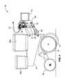
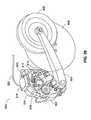
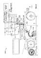
- FIG. 1is a perspective view of a planting row unit attached to a towing frame.
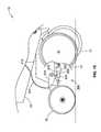
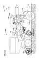
- FIG. 2is a partially sectioned side elevation of the planting row unit of FIG. 1 with the linkage that connects the row unit to the towing frame in a level position.
- FIG. 3is the same side elevation shown in FIG. 1 but with the linkage tilted upwardly to move the row unit to a raised position.
- FIG. 4is the same side elevation shown in FIG. 1 but with the linkage tilted downwardly to move the row unit to a lowered position.
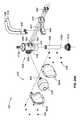
- FIG. 5is a top plan view of the hydraulic cylinder and accumulator unit included in the row unit of FIGS. 1-4 .
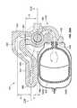
- FIG. 6is a vertical section taken along line 6 - 6 in FIG. 5 .
- FIG. 7is a side elevation of the unit shown in FIGS. 5 and 6 connected to a pair of supporting elements, with the support structures and the connecting portions of the hydraulic cylinder shown in section.
- FIGS. 8A and 8Bare enlarged cross sectional views of the supporting structures shown in section in FIG. 7 .
- FIG. 9is an enlarged perspective of the right-hand end portion of FIG. 1 with a portion of the four-bar linkage broken away to reveal the mounting of the hydraulic cylinder/accumulator unit.
- FIG. 10is a schematic diagram of a first hydraulic control system for use with the row unit of FIGS. 1-9 .
- FIG. 11is a schematic diagram of a second hydraulic control system for use with the row unit of FIGS. 1-9 .
- FIG. 12is a diagram illustrating one application of the hydraulic control system of FIG. 11 .
- FIG. 13is a side elevation of a modified embodiment having the hydraulic control unit coupled to the closing wheels of the row unit;
- FIG. 14is a side elevation of a further modified embodiment having the hydraulic control unit coupled to the closing wheels of the row unit;
- FIG. 15is yet another modified embodiment having the hydraulic control unit coupled to the closing wheels of the row unit;
- FIG. 16is a side elevation of another modified embodiment of a hydraulic control unit
- FIG. 17is an enlarged section taken along the line 17 - 17 in FIG. 16 ;
- FIG. 18is a schematic diagram of the hydraulic circuit in the unit of FIGS. 16 and 17 .
- FIG. 19is a perspective view of a standard configuration of a hydraulic system.
- FIG. 20Ais an exploded view of a standard configuration of a hydraulic assembly.
- FIG. 20Bis an assembled perspective view of FIG. 20A .
- FIG. 21is a perspective view of a hose connection manifold.
- FIG. 22Ais a top cross-sectional view of FIG. 20B .
- FIG. 22Bis a side cross-sectional view of FIG. 20B .
- FIG. 23is a rear perspective view of an alternative configuration of the hydraulic system of FIG. 19 .
- FIG. 24Ais an exploded view of an alternative configuration of a hydraulic assembly.
- FIG. 24Bis an assembled perspective view of FIG. 24A .
- FIG. 25Ais a perspective view of a control manifold.
- FIG. 25Bis a left cross-sectional view of the control manifold of FIG. 25A .
- FIG. 25Cis a right cross-sectional view of the control manifold of FIG. 25A .
- FIG. 26is a top plan view of a hydraulic cylinder for a row unit.
- FIG. 27Ais a vertical section taken along line 27 A- 27 A in FIG. 26 .
- FIG. 27Bis an enlarged view of a ram leading area that is shown in FIG. 27A .
- FIG. 28Ais a side elevation of a hydraulic control system with double-acting ram for use with a row unit.
- FIG. 28Bis an enlarged view illustrating a hydraulic control unit of the hydraulic control system of FIG. 28A .
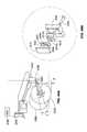
- FIG. 29is a perspective view of an agricultural opener device with integrated controller.
- FIG. 30is a schematic diagram of a hydraulic control system having integrated controllers in one or more row units.
- FIG. 31is a schematic diagram of a hydraulic control system for use with a row unit.
- FIG. 32is a partial perspective of a linkage assembly with two actuators for controlling a row unit.
- FIG. 33is a side illustration of the linkage assembly of FIG. 32 .
- FIG. 34illustrates an actuator having two energy storage devices.
- FIG. 35illustrates a tractor towing a plurality of row units having status indicators.
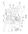
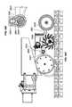
- FIG. 36is a perspective view of a soil-hardness sensing device attached to a planting row unit.
- FIG. 37is a schematic side elevation illustrating the soil-hardness device attached to the planting row unit.
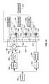
- FIG. 38is a schematic diagram illustrating the determination of hydraulic pressures for a planting row unit.
- FIG. 39Ais a side elevation of an agricultural system moving over soft soil conditions.
- FIG. 39Bis a side elevation of the agricultural system of FIG. 39A in which a soil-hardness sensing device is moving over hard soil conditions.
- FIG. 39Cis a side elevation of the agricultural system of FIG. 39B in which a planting row unit is moving over the hard soil conditions.
- FIG. 40Ais a schematic side elevation illustrating sensing of soil conditions and determining of hydraulic pressures for a planting row unit.
- FIG. 40Bis a flowchart of an algorithm for adjusting a pressure applied to a soil-hardness sensing device.
- FIG. 40Cis a flowchart of an algorithm for adjusting a user-defined variable associated with a pressure applied to a planting row unit.
- FIG. 40Dis a flowchart of an algorithm for adjusting a user-defined variable associated with a pressure applied to a row-clearing unit.
- FIG. 41Ais a top elevation illustrating an agricultural system in which a plurality of planting row units are adjusted by two soil-hardness sensing devices.
- FIG. 41Bis a side elevation illustrating the agricultural system of FIG. 41B .
- FIG. 42is a side elevation illustrating an alternative embodiment of the soil-hardness sensing device with modular actuators.
- FIG. 43is a perspective view illustrating an alternative modular unit.
- FIG. 44Ais side elevation illustrating an alternative embodiment of the soil-hardness sensing device with a modified blade arm.
- FIG. 44Bis an enlarged exploded illustration of a distal end of the blade arm.
- FIG. 44Cis a side elevation of a row unit having a ground hardness sensor integrated with a furrow-closing device that includes a pair of toothed wheels and a ground gauge wheel.
- FIG. 44Dis an enlarged sectional view of a proximity sensing device included in the ground hardness sensor in the row unit shown in FIG. 44C .
- FIG. 44Eis the same side elevation shown in FIG. 44C , with the closing wheels at a higher elevation than shown in FIG. 44C .
- FIG. 44Fis an enlarged sectional view of the proximity sensor shown in FIG. 44D , with the closing wheels in the position shown in FIG. 44E .
- FIG. 44Gis an enlarged exploded perspective view of the closing wheel support arm shown in FIGS. 44C-44F , and the sensing device coupled to the upper end of that support arm.
- FIG. 45is a schematic diagram of a hydraulic control system for controlling the hydraulic pressure in a hydraulic cylinder.
- FIG. 46Ais a schematic diagram of a modified hydraulic control system for controlling the hydraulic pressure in a hydraulic cylinder.
- FIG. 46Bis a waveform diagram illustrating different modes of operation provided by the hydraulic control systems of FIGS. 45 and 46A .
- FIG. 46Cis a diagrammatic illustration of an electrical control system for use with the hydraulic control systems of FIGS. 45 and 46A .
- FIG. 47is a side elevation of a planting row unit and a row-clearing unit, both attached to a towing frame, with the row-clearing unit in a lowered position.
- FIG. 48is the same side elevation shown in FIG. 47 with the row-clearing unit in a raised position.
- FIG. 49is an enlarged perspective of the row-clearing unit shown in FIGS. 47 and 48 .
- FIGS. 50, 51 and 52are side elevations of the main components of the row-clearing unit shown in FIGS. 47-49 in three different vertical positions.
- FIGS. 53, 54 and 55are side elevations of the hydraulic cylinder of the row-clearing unit shown in FIGS. 47-52 with the cylinder rod in three different positions corresponding to the positions shown in FIGS. 51, 52 and 50 , respectively.
- FIG. 56is a schematic diagram of a first hydraulic control system for use in controlling the row-clearing unit shown in FIGS. 47-52 .
- FIG. 57is a schematic diagram of a second hydraulic control system for use in controlling the row-clearing unit shown in 47 - 52 .
- FIG. 58is a functional block diagram of a hydraulic control system for use with multiple row units.
- FIG. 59is a perspective view similar to that of FIG. 49 but modified to include a pressure sensor, in the form of a load cell.
- FIG. 60is an enlarged section view taken longitudinally through the middle of the load cell shown in FIG. 59 .
- FIG. 61is a side elevation of a modified embodiment having multiple control systems.
- FIG. 62is a block diagram of the multiple control systems for multiple row units of the type illustrated in FIG. 61 , and a display coupled to the control systems in the multiple row units.
- FIG. 63is a block diagram of a slightly simplified version of the system illustrated in FIG. 62 .
- FIG. 64is a a block diagram of a further simplified version of the system illustrated in FIG. 62 .
- FIG. 65is a block diagram of multiple control valves for multiple row units arranged in multiple groups or sections.
- FIG. 66Ais an exemplary display configured to depict real-time graphics when an implement is moving across a field.
- FIG. 66Bis an exemplary display depicting real-time graphics of one or more performance metrics relating to a tool as it is moving across a field.
- FIG. 66Cis an exemplary display depicting a modified screen for monitoring one or more parameters associated with one or more tools across all the row units of a planter.
- FIG. 66Dshows an exemplary number keypad that can be used by the operator to quickly select a row unit for immediate monitoring as the row units are being moved across a field.
- FIG. 66Eis an exemplary display depicting an exemplary row diagnostics screen with tool parameter monitor windows.
- FIG. 67is a series of plots representing the variations in electrical parameters representing the performance of an implement as it traverses an agricultural field.
- FIG. 68is an exemplary touch-screen display depicting a control panel for use by an operator to select the type of tool to be monitored on the display.
- FIG. 69is exemplary display depicting an interactive map screen.
- FIG. 70is a flowchart of an algorithm that can be used in connection with FIG. 40B .
- a planting row unit 10includes a furrow-opening device for the purpose of planting seed or injecting fertilizer into the soil.
- the furrow-opening deviceis a V-opener 11 formed by a pair of conventional tilted discs depending from the leading end of a row unit frame 12 .
- a conventional elongated hollow towing frame 13(typically hitched to a tractor by a draw bar) is rigidly attached to the front frame 14 of a conventional four-bar linkage assembly 15 that is part of the row unit 10 .
- the four-bar (sometimes referred to as “parallel-bar”) linkage assembly 15is a conventional and well known linkage used in agricultural implements to permit the raising and lowering of tools attached thereto.
- the V-opener 11penetrates the soil to form a furrow or seed slot. Other portions of the row unit 10 then deposit seed in the seed slot and fertilizer adjacent to the seed slot, and close the seed slot by distributing loosened soil into the seed slot with a pair of closing wheels 16 .
- a gauge wheel 17determines the planting depth for the seed and the height of introduction of fertilizer, etc.
- Bins 18 a and 18 b on the row unitcarry the chemicals and seed which are directed into the soil.
- the planting row unit 10is urged downwardly against the soil by its own weight, and, in addition, a hydraulic cylinder 19 is coupled between the front frame 14 and the linkage assembly 15 to urge the row unit 11 downwardly with a controllable force that can be adjusted for different soil conditions.
- the hydraulic cylinder 19may also be used to lift the row unit off the ground for transport by a heavier, stronger, fixed-height frame that is also used to transport large quantities of fertilizer for application via multiple row units.
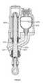
- the hydraulic cylinder 19is shown in more detail in FIGS. 5 and 6 .
- Pressurized hydraulic fluid from the tractoris supplied by a hose 20 to a port 21 that leads into a matching port 22 of a housing 23 that forms a cavity 24 of a hydraulic cylinder containing a ram 25 .
- the housing 23also forms a side port 26 a that leads into cavity 26 b that contains a gas-charged hydraulic accumulator 27 .
- the lower end of the cavity 24is formed by the top end surface of the ram 25 , so that the hydraulic pressure exerted by the hydraulic fluid on the end surface of the ram 25 urges the ram downwardly (as viewed in FIG. 6 ), with a force determined by the pressure of the hydraulic fluid and the area of the exposed end surface of the ram 25 .
- the hydraulic fluidthus urges the ram 25 in an advancing direction (see FIG. 4 ).
- the hydraulic cylinder 19 and the accumulator 27are mounted as a single unit on the front frame 14 , with the lower end of the ram 25 connected to a cross bar 30 that is joined at one end to a vertical link 31 .
- the upper and lower ends of the link 31are pivotably attached to upper and lower links 15 a and 15 b , respectively, on one side of the four-bar linkage 15 .
- the other end of the cross bar 30is angled upwardly and pivotably attached to the upper link 15 c on the opposite side of the four-bar linkage 15 .
- the accumulator 27includes a diaphragm 28 that divides the interior of the accumulator into a hydraulic-fluid chamber 29 a and a gas-filled chamber 29 b , e.g., filled with pressurized nitrogen.
- FIG. 2shows the ram 25 in a position where the diaphragm 28 is not deflected in either direction, indicating that the pressures exerted on opposite sides of the diaphragm are substantially equal.
- FIG. 3the ram 25 has been retracted by upward movement of the row unit, and the diaphragm 28 is deflected downwardly by the hydraulic fluid forced into the accumulator 27 by the retracting movement of the ram 25 .
- FIG. 3shows the ram 25 in a position where the diaphragm 28 is not deflected in either direction, indicating that the pressures exerted on opposite sides of the diaphragm are substantially equal.
- FIG. 3the ram 25 has been retracted by upward movement of the row unit, and
- the ram 25has been withdrawn to its most retracted position, which can occur when the row unit encounters a rock or other obstruction, for example.
- the row unitis in its uppermost position.
- retracting movement of the ram 25is limited by engagement of stops 40 , 42 on the lower links of the four-bar linkage 15 , with the row unit frame 12 .
- Retracting movement of the ram 25reduces the volume of the cavity 24 (see FIG. 3 ), which causes a portion of the fixed volume of hydraulic fluid in the cylinder 19 to flow into the chamber 29 a of the accumulator 27 , causing the diaphragm 28 to deflect to the position illustrated in FIG. 3 .
- This deflection of the diaphragm 28 into the chamber 29 bcompresses the gas in that chamber.
- the hydraulic fluidTo enter the chamber 29 a , the hydraulic fluid must flow through a port 32 in the top of the accumulator 27 , which limits the rate at which the hydraulic fluid flows into the accumulator.
- This controlled rate of flow of the hydraulic fluidhas a damping effect on the rate at which the ram 25 retracts or advances, thereby avoiding sudden large movements of the moving parts of the row unit, including the V-opener 11 . This effect also minimizes vibration to improve accuracy of seed metering.
- the single unitary housing 23forms both the cavity 26 b that contains the accumulator 27 and the cavity 24 of the hydraulic cylinder 19 and the fluid passageway 24 that connects the cavity 24 of the hydraulic cylinder 19 to the cavity 27 of the accumulator.
- the accumulator 27which is by definition an energy storage device, to be mounted in a fully enclosed and safe housing.
- the accumulator 27can be securely mounted to avoid puncture or rapid discharge (if it comes loose), or damage from hitting another part of the implement or a foreign object.
- the integrated cylinder and accumulatoris also a convenient single package for installation and replacement and minimizes the number of hydraulic hoses and adapters (potential leakage points).
- FIGS. 7, 8A and 8Billustrate in more detail how the illustrative hydraulic cylinder/accumulator unit is attached to the front frame 14 and the linkage assembly 15 .
- the top of the unitary housing 23forms a stem 41 that projects upwardly through a hole 51 in a bracket 50 attached to the front frame 14 .
- the outer surface of the stem 41is threaded to receive a nut 52 that connects the housing 23 to the bracket 50 .
- the hole 51is oversized and a rubber washer is installed on the stem 41 between the nut 52 and the bracket 50 to allow a limited amount of tilting movement of the housing relative to the bracket 50 .
- the housing 23forms a shoulder 43 that engages a conical bearing ring 53 that also engages a mating lower surface of a washer 54 .
- the housing 23can be tilted relative to the axis of the hole 51 , with the shoulder 43 sliding over the lower surface of the bearing ring 53 .
- a similar arrangementis provided at the lower end of the ram 25 , where a stem 60 extends downwardly through a hole 61 in the cross bar 30 that is pivotably attached to the linkage assembly 15 .
- a nut 62is threaded onto the stem 60 to connect the ram to the cross bar 30 .
- the hole 61is oversized and a rubber washer is installed on the stem 60 between the nut 62 and the cross bar 30 to allow a limited amount of tilting movement of the ram 25 relative to the cross bar 30 .
- a flange 63 on the ram 25forms a curved conical surface 64 that engages a mating surface of a curved conical bearing ring 65 that also engages a mating upper surface of a washer 66 .
- the ram 25can be tilted relative to the axis of the hole 61 , with the flange 63 sliding over the upper surface of the bearing ring 65 .
- the use of a hydraulic systempermits on-the-go adjustments to be made very rapidly because the hydraulic fluid is incompressible and therefore acts more directly than an air system.
- hydraulic fluidstypically operate at higher pressures, which allow greater changes in applied forces.
- the accumulator 27allows the fluid system to flex and float with the changing terrain and soil conditions.
- the accumulator 27is preferably centrally mounted so that when any single row unit moves over an obstruction, the down-pressure cylinder 19 moves to displace the hydraulic fluid along a common set of lines connecting all row units.
- the gas in the accumulatoris compressed at the same time, allowing for isolation among the row units so that upward movement of one row unit does not cause downward movement of other row units.
- the illustrative hydraulic ramis single-acting, it is also possible to use a double-acting ram, or a single-acting ram in combination with a return spring.
- the compact hydraulic cylinder/accumulator unitcan be conveniently mounted to the same brackets that are provided in many row units for mounting an air bag, to control the down pressure on the row unit.
- the brackets 50 and 51 on which the hydraulic cylinder/accumulator is mountedare the brackets that are often connected to an air bag, and thus the same row unit can be used interchangeably with either an air bag or the hydraulic cylinder/accumulator to control the down pressure on the row unit.
- FIG. 10is a schematic of a hydraulic control system for supplying pressurized hydraulic fluid to the cylinders 19 of multiple row units.
- a source 100 of pressurized hydraulic fluidtypically located on a tractor, supplies hydraulic fluid under pressure to a valve 101 via supply line 102 and receives returned fluid through a return line 103 .
- the valve 101can be set by an electrical control signal S 1 on line 104 to deliver hydraulic fluid to an output line 105 at a desired constant pressure.
- the output line 105is connected to a manifold 106 that in turn delivers the pressurized hydraulic fluid to individual feed lines 107 connected to the ports 21 of the respective hydraulic cylinders 19 of the individual row units.
- the valve 101is turned off, preferably by a manually controlled on/off valve V, after all the cylinders 19 have been filled with pressurized hydraulic fluid, to maintain a fixed volume of fluid in each cylinder.
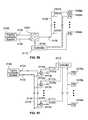
- FIG. 11is a schematic of a modified hydraulic control system that permits individual control of the supply of hydraulic fluid to the cylinder 19 of each separate row unit via feed lines 107 connected to the ports 21 of the respective cylinders 19 , or to control valves for those cylinders. Portions of this system that are common to those of the system of FIG. 10 are identified by the same reference numbers. The difference in this system is that each separate feed line 107 leading to one of the row units is provided with a separate control valve 110 that receives its own separate control signal on a line 111 from a controller 112 .
- This arrangementpermits the supply of pressurized hydraulic fluid to each row unit to be turned off and on at different times by the separate valve 110 for each unit, with the times being controlled by the separate control signals supplied to the valves 110 by the controller 112 .
- the individual valves 110receive pressurized hydraulic fluid via the manifold 106 , and return hydraulic fluid to a sump on the tractor via separate return line 113 connected to a return manifold 114 connected back to the hydraulic system 100 of the tractor.
- FIG. 12illustrates on application for the controllable hydraulic control system of FIG. 11 .
- Modern agricultural equipmentoften includes GPS systems that enable the user to know precisely where a tractor is located in real time.
- GPS systemsthat enable the user to know precisely where a tractor is located in real time.
- each planting row unit 120can be turned off just as it enters the headland 122 , to avoid double-planting while the tractor 121 makes a turn through the headland.
- the hydraulic cylinder 19 of each row unitcan also be separately controlled to turn off the supply of pressurized hydraulic fluid at a different time for each row unit, so that each row unit is raised just as it enters the headland, to avoid disrupting the rows already planted in the headland.
- FIG. 11One benefit of the system of FIG. 11 is that as agricultural planters, seeders, fertilizer applicators, tillage equipment and the like become wider with more row units on each frame, often 36 30-inch rows or 54 20-inch rows on a single 90-foot wide toolbar, each row unit can float vertically independently of every other row unit. Yet the following row units still have the down force remotely adjustable from the cab of the tractor or other selected location. This permits very efficient operation of a wide planter or other agricultural machine in varying terrain without having to stop to make manual adjustment to a large number of row units, resulting in a reduction in the number of acres planted in a given time period. One of the most important factors in obtaining a maximum crop yield is timely planting.
- each row unitor group of units
- the ability to quickly release all down force on the row unit when approaching a wet spot in the fieldone can significantly increase the planter productivity or acres planted per day, thereby improving yields and reducing costs of production.
- the toolbar-frame-mounted row unitpermits the planter row unit following independently behind to use less down force for its function, resulting in more uniform seed depth control and more uniform seedling emergence. More uniform seedling stands usually result in higher yields than less uniform seedling stands produced by planters with less accurate row cleaner ground following.
- FIGS. 13-15illustrate modified embodiments in which the hydraulic cylinder 200 urges the closing wheels 16 downwardly with a controllable force that can be adjusted for different conditions.
- pressurized hydraulic fluid from the tractoris supplied by a hose 201 to a port 202 of a housing 203 that forms a cavity of a hydraulic cylinder 204 containing a ram 205 .
- the housing 203also forms a side port 206 that leads into a cavity 207 that contains a gas-charged hydraulic accumulator 208 .
- the lower end of the cavity 204is formed by the top end surface of the ram 205 , so that the hydraulic pressure exerted by the hydraulic fluid on the end surface of the ram 205 urges the ram downwardly (as viewed in FIG. 13 ), with a force determined by the pressure of the hydraulic fluid and the area of the exposed end surface of the ram 205 .
- the hydraulic fluidthus urges the ram 205 in a downward direction.
- the hydraulic cylinder 204 and the accumulator 208are pivotably mounted as a single unit on the row unit frame 210 , with the lower end of the ram 205 pivotably connected to a linkage 211 that carries the closing wheels 16 .
- advancing movement of the ram 205 in the cylinder 204tilts the linkage 211 downwardly, thereby urging the closing wheels 16 downwardly.
- retracting movement of the ram 205tilts the linkage 211 upwardly, thereby raising the closing wheels 16 .
- FIG. 14illustrates an arrangement similar to FIG. 13 except that the hydraulic cylinder 204 is charged with a pressurized gas in chamber 212 on the side of the ram 205 that is not exposed to the pressurized fluid from the hose 201 .
- the hydraulic cylinder 204is positioned such that advancing movement of the ram 205 in the cylinder 204 tilts the linkage 211 upwardly, thereby raising the closing wheels 16 .
- the hydraulic control unithas an added biasing element 220 on the side of the ram 205 that is not exposed to the pressurized hydraulic fluid.
- This biasing element 220may be in addition to, or in place of, pressurized gas in the hydraulic cylinder 204 .
- the biasing element 220may be formed by various types of mechanical springs, such as a compressed coil spring, or may be pressurized air, nitrogen or other gas.
- FIGS. 16-18illustrate a modified hydraulic control unit that includes a hydraulic cylinder 300 containing a ram 301 that can be coupled at its lower end to a device on which the down pressure is to be controlled. Pressurized hydraulic fluid is supplied to the upper end of the cylinder 301 through a port 304 .
- the cylinder 300includes a side port 302 leading to an accumulator 303 of the type described above in connection with FIGS. 5 and 6 .
- the entry port 305 to the accumulator 303is equipped with a check valve 306 and restriction 307 as illustrated in FIG. 18 .
- hydraulic fluidflows from the cylinder 300 into the accumulator 303 via the restriction 307 .
- the restrictionacts as a damper to reduce the shock on the equipment and avoid excessive upward movement of the ram 301 .
- hydraulic fluidflows from the accumulator back into the cylinder 300 via the check valve 306 , which allows unrestricted flow in this direction so that the controlled device quickly re-engages the ground with the down pressure exerted by the hydraulic fluid on the upper end of the ram 301 .
- the check valve unitcan be easily installed in the accumulator entry port 305 . Additionally, the check valve unit can have an orifice system that is bidirectional for damping motion, both in and out.
- row unitrefers to a unit that is attached to a towing frame in a way that permits the unit to move vertically relative to the towing frame and other units attached to that same towing frame. Most row units are equipped to form, plant and close a single seed furrow, but row units are also made to form, plant and close two or more adjacent seed furrows.
- a hydraulic system 400includes a hydraulic assembly 401 , a front frame 404 , and a four-bar linkage assembly 406 .
- the four-bar linkage assembly 406is generally similar to the four-bar linkage assembly 15 described above in reference to FIGS. 1-9 .
- the four-bar linkage assembly 406includes a pair of parallel lower links 408 a , 408 b , a pair of parallel upper links 410 a , 410 b , and a cross bar 412 .
- the hydraulic assembly 401is rigidly attached to the four-bar linkage assembly 406 on a row-unit side, and the front frame 404 is pivotably attached to the four-bar linkage assembly 406 on a towing side.
- the hydraulic assembly 401includes a hydraulic cylinder 402 , an accumulator protective cover 420 , and a hose connection manifold 424 .
- the hydraulic cylinder 402is generally similar to the hydraulic cylinders 19 , 204 described above in reference to FIGS. 1-9 and 13-18 , and includes an upper end 413 a and a lower end 413 b .
- the upper endis mounted to a bracket 414 of the linkage assembly 406
- the lower end 413 bis mounted to the cross bar 412 of the linkage assembly 406 .
- a gland and securing nut 418(with internal seals) is interposed at the lower end 413 b between the hydraulic cylinder 402 and the cross bar 412 .
- the accumulator protective cover 420is mounted adjacent to and between a left upper link 410 b and the hydraulic cylinder 402 .
- the accumulator protective cover 420shields from environmental contaminants and physical damage an accumulator 422 (shown in FIG. 20A ).
- the accumulator protective cover 420itself is provided with protection from physical damage, e.g., caused by debris, rocks, etc., by being located between the pair of upper links 410 a , 410 b .
- the upper links 410 , 410 bdo not completely shield the accumulator protective cover 420 , the upper links 410 , 410 b provide some protection from physical damage while, simultaneously, allowing ease of access for servicing and/or replacing the accumulator 422 .
- the hose connection manifold 424which is described in more detail below in reference to FIG. 21 , is mounted adjacent to and between a right upper link 410 a and the hydraulic cylinder 402 .
- the hose connection manifold 424is configured such that it does not interfere with any of the other components of the hydraulic system 400 , including the right upper link 410 a , the hydraulic cylinder 402 , and the accumulator protective cover 420 .
- the hose connection manifold 424is coupled at a distal end to a pair of hydraulic fluid hoses, including an inlet hose 426 and an outlet hose 428 .
- the inlet hose 426receives and delivers hydraulic fluid from an adjacent row unit, and the outlet hose 428 connects to another adjacent row unit.
- the attachment of the hoses 426 , 428 to the hose connection manifold 424in a position that is spaced away from the relatively more-cluttered area of the hydraulic cylinder 402 and bracket 414 , facilitates easy field servicing of the hoses 426 , 428 .
- a usercan easily couple/uncouple the hoses 426 , 428 to/from the hose connection manifold 424 by having a clear path directly to the hose connection manifold 424 .
- the accumulator protective cover 420includes a right cover 420 a and a left cover 420 b that are fastened to each other via a plurality of small nuts 434 and bolts 436 .
- the accumulator 422Enclosed within the accumulator protective cover 420 is the accumulator 422 , which has an accumulator end 430 that is inserted into a accumulator receiver 432 of the hydraulic cylinder 402 .
- the accumulator receiver 432extends from a main body 433 of the hydraulic cylinder 402 a sufficient distance to permit the mounting of the accumulator protective cover 420 without interfering with the hose connection manifold 424 (as further illustrated in FIG. 22A ).
- the main body 433 of the hydraulic cylinder 402receives a spherical rod 438 for axial mounting below the accumulator receiver 432 .
- the gland 418is threaded into the hydraulic cylinder 402 after the spherical rod 438 is installed on the hydraulic cylinder 402 .
- the gland 418contains internal seals and wear rings to hold pressure and seal out contaminants.
- the hydraulic cylinder 402further includes a mounting interface 440 extending from the main body 433 in an opposite direction relative to the accumulator receiver 432 .
- the hose connection manifold 424is mounted directly to the mounting interface 440 via a plurality of long bolts 442 that are received, respectively, in a plurality of threaded holes 444 .
- An O-ring seal 441is positioned between the control manifold 424 and the hydraulic cylinder 402 to prevent leakage of hydraulic fluid.
- the hose connection manifold 424has a mounting face 456 (shown in FIG. 21 ) that is aligned, when mounted, in contact with a receiving face 443 of the mounting interface 440 .
- the mounting face 456 of the hose connection manifold 424 and the receiving face 443 of the mounting interface 440are configured such that they are complementary mating faces with the O-ring seal 441 holding pressure between the components.
- the mounting interface 440further facilitates a modular exchange between hose connection manifolds of different types.
- the hose connection manifold 424is an example of a standard configuration in which the manifold functions solely to attach hydraulic hoses and to circulate hydraulic fluid between the hydraulic source and the hydraulic cylinder 402 .
- the same mounting interface 440(without reliance on additional components or tools) is used to attach a manifold of a different type.
- This modular exchange between different manifold typesis beneficial for quick and easy replacement of the manifolds based on current planting needs, which can quickly change in real time due to weather conditions, terrain conditions, etc.
- a pair of hose ends 446 , 448are attached to the hose connection manifold 424 at a distal end 450 for coupling the inlet and outlet hoses 426 , 428 .
- an inlet hose-end 446is coupled to the inlet hose 426 and an outlet hose-end 446 is coupled to the outlet hose 428 .
- the hose ends 446 , 448are attached to the distal end 450 in a generally parallel configuration relative to a central axis of the hydraulic cylinder 402 .
- the attachment configuration of the hose ends 446 , 448 to the hose connection manifold 424facilitates easy access and servicing of the inlet and outlet hoses 426 , 428 .
- the hose connection manifold 424is a valve-less manifold that lacks a control valve or a control module (in contrast to the integrated control manifold 524 discussed below in reference to FIGS. 23-25C ).
- the hose connection manifold 424has a mounting end 452 that is separated from the distal end 450 by a manifold arm 454 .
- the manifold arm 454includes a curved section that offsets the mounting face 456 of the mounting end 452 by a distance D from an exterior surface 466 of the distal end 450 .
- the offset distance Dis helpful in minimizing space requirements for mounting the hose connection manifold 424 within the space defined by the upper links 410 , 410 b of the linkage assembly 406 .
- the manifold arm 454is positioned generally parallel to the accumulator 422 .
- the mounting face 456includes a plurality of mounting holes 458 arranged in a concentric pattern around a central hydraulic hole 459 , through which hydraulic fluid is delivered to the hydraulic cylinder 402 .
- the pattern of the mounting holes 458matches a pattern of the threaded holes 444 of the mounting interface 440 .
- the hydraulic hole 459is internally connected to an inlet port 460 and an outlet port 462 via an internal channel 464 (illustrated in FIG. 22A ).
- the inlet port 460is adapted to receive the inlet hose-end 446 , to which the inlet hose 426 is coupled
- the outlet port 462is adapted to receive the outlet hose-end 446 , to which the outlet hose 428 is coupled.
- the inlet and outlet ports 460 , 462are aligned with a central axis of the internal channel 464 and are oriented perpendicular to the orientation of the hydraulic hole 459 . Additionally, the spacing between the inlet port 460 and the outlet port 462 facilitates parallel coupling of the two hose ends 446 , 448 adjacent to each other.
- the configuration of the hydraulic assembly 401facilitates delivery of hydraulic fluid to the hydraulic cylinder 402 in a relatively space-constrained environment while still providing easy access to main components, including the accumulator 422 and the hose connection manifold 424 , for service and replacement.
- hydraulic fluidcirculates unrestricted between the hose connection manifold 424 , the hydraulic cylinder 402 , and the accumulator 422 via the internal channel 464 .
- the geometric configuration of the hose connection manifold 424facilitates mounting the accumulator protective cover 420 close to the distal end 450 of the hose connection manifold 424 at a relatively small distance Z, thus minimizing required mounting space, without causing interference between the hose connection manifold 424 and the accumulator protective cover 420 .
- the distal end 450is further defined by a distance X that separates two extreme points of a central axis of the internal channel 464 .
- distance Xis defined by a point of the central axis near the distal end 450 and a point of the central axis near the mounting end 452 .
- the inlet hose 426 and the outlet hose 428can be easily and quickly removed, in the field, based at least on their parallel upward attachment to the hose connection manifold 424 .
- the inlet hose 426 and the outlet hose 428can be daisy chained when using a typical side-by-side arrangement of row units.
- a first row unitis connected directly to the hydraulic source via its inlet hose and directly to the inlet port of an adjacent second row unit via its outlet hose.
- the second row unitreceives hydraulic fluid, indirectly, from the hydraulic source via the first row unit.
- the second row unitis further daisy chained to an adjacent third row unit such that the outlet hose of the second row unit is directly connected to the inlet port of the third row unit.
- This type of daisy-chain configurationcan continue with dozens of row units.
- one of the two ports 460 , 462is plugged and a tee is placed in front of the row unit such that a single hose is connected to the hydraulic cylinder 402 .
- the hose connection manifold 424has been replaced with the integrated control manifold 524 that includes both an electronic control module 525 and a connection manifold 527 (both shown in FIGS. 24A and 24B ).
- the control manifold 524is configured to fit within the upper links 410 a , 410 b next to the accumulator protective cover 420 , similar to the hose connection manifold 424 .
- the control manifold 524does not interfere with any components of the hydraulic system 400 .
- control manifold 524is further connected to a control signal wire 529 for receiving control signals from a central processing unit.
- each row unit of a plurality of adjacent row unitshas its own pressure control valve. Assuming that the control manifold 524 is mounted in each of the plurality of row units, the down pressure in each row unit can be individually controlled. To achieve individual control, both the inlet hose 426 and the outlet hose 428 of each row unit are connected to the hydraulic source in parallel. For example, the inlet hose of a first row unit is connected to the tractor for supplying constant pressure to the first row unit, and the outlet hose of the first row unit is also connected to the tractor for returning hydraulic fluid from the first row unit.
- the inlet hose of a second row unitis connected to the tractor for supplying constant pressure to the second row unit, and the outlet hose of the second row unit is also connected to the tractor for returning hydraulic fluid from the second row unit.
- the pressure in the first and second row unitscan be independently controlled.
- the control manifold 524is mounted to the hydraulic cylinder 402 using the same long bolts 442 , which are fastened to the threaded holes 444 .
- the control manifold 524has a mating face 556 (shown in FIGS. 25A-25C ) that is generally similar (if not identical) to the mating face 456 of the hose connection manifold 424 .
- the mating face 556is configured as a mating face for facilitating attachment of the control module 524 to the mounting interface 440 (similar to the attachment of the hose connection manifold 424 to the mounting interface 440 ).
- An O-ring seal 541is positioned between the control manifold 524 and the hydraulic cylinder 402 to prevent leakage of hydraulic fluid.
- the hose ends 446 , 448are received in respective inlet and outlet ports 560 , 562 for facilitating coupling of the hoses 426 , 428 to the control module 542 .
- the inlet and outlet ports 460 , 462 of the hose connection manifold 424are oriented perpendicular to (not parallel to) the central axis of the hydraulic cylinder 402 . Nevertheless, a user can still reach with relative ease the connection between hoses 426 , 428 and the ports 560 , 562 for service-related needs.
- the control module 525includes a hydraulic valve cartridge 531 for reducing and/or relieving pressure in hydraulic cylinder 402 .
- the valve cartridge 531is enclosed within the control module 525 and has one end inserted in a cartridge port 533 of the connection manifold 527 .
- the valve cartridge 531reduces pressure in the hydraulic cylinder 402 and, optionally, acts as a relief valve relieving any shocks or surges that may occur between the hydraulic source and the hydraulic cylinder 402 .
- the control module 525optionally includes a pressure transducer 535 and/or other embedded electronics.
- an integrated electronic connector 537 of the control module 525is positioned above the valve cartridge 531 for receiving electrical power via an electrical cable (not shown).
- the electronic connector 537is angled towards the accumulator protective cover 420 to provide sufficient space for connecting all the required cables and hoses to the control module 525 , e.g., the inlet and outlet hoses 426 , 428 , the control signal wire 529 , and the electrical cable.
- connection manifold 527is configured to facilitate the integral combination with the control module 525 .
- the connection manifold 527has a mounting face 556 that is aligned, when mounted with the receiving face 443 of the mounting interface 440 .
- the mounting face 556 of the connection manifold 527is generally similar (if not identical) to the mounting face 456 of the hose connection manifold 424 .
- the mounting face 556includes a plurality of mounting holes 558 arranged in a concentric pattern around a central hydraulic hole 559 , through which hydraulic fluid is delivered to the hydraulic cylinder 402 .
- the pattern of the mounting holes 558matches a pattern of the threaded holes 444 of the mounting interface 440 .
- the hydraulic hole 559is internally connected to the inlet port 560 , the outlet port 562 , the cartridge port 533 , and a transducer port 539 .
- the connection manifold 527includes the additional cartridge port 533 for coupling to the valve cartridge 531 (which controls output of fluid pressure from the hydraulic cylinder 402 ) and the transducer port 539 for coupling to the pressure transducer 535 .
- the portsare positioned along a control face 541 , which is generally perpendicular to the mounting face 556 .
- connection manifold 527 and the hose connection manifold 424share some similarities (e.g., sharing the modular mounting interface 440 ), they are different in type at least based on the connection manifold 527 being configured geometrically to facilitate the integration with the control module 525 .
- a hydraulic cylinder 619 and energy storage device 627are generally similar to the hydraulic cylinder 19 and accumulator 27 described and illustrated above in reference to FIGS. 5 and 6 .
- a single unitary housing 623forms a cavity 624 in which the hydraulic cylinder 619 and the energy storage device 627 are enclosed, at least in part.
- the hydraulic cylinder 619contains a ram 625 that advances towards a housing port 622 or retracts towards a stem 660 .
- the ram 625has a leading edge 650 near which a wear ring 652 is mounted.
- the wear ring 652is mounted on the ram 625 concentric with a central axis Z of the ram 625 and in physical contact (or close to being in physical contact) with a cylinder wall 654 .
- the wear ring 652can be a seal or some other component that can provide a barrier zone between the ram 625 and the cylinder wall 654 .
- the wear ring 652can have a cylindrical cross-sectional profile (as illustrated in FIG. 27B ) or any other cross-sectional profile.
- the wear ring 652guides the ram 625 within the cylinder wall 654 of the hydraulic cylinder 619 , absorbing transverse forces.
- the wear ring 652further prevents (or reduces) metal-to-metal contact between the ram 625 and the cylinder wall 654 and, thus, optimizes the performance of the hydraulic cylinder 619 .
- one benefit of the wear ring 652is that it prevents or reduces wear of the ram 625 due to frictional contact with the cylinder wall 654 .
- Another benefit of the wear ring 652is that it tends to act as a seal component (although not necessarily specifically intended to be a seal component).
- tight tolerances between the ram 625 and the cylinder wall 654help achieve a sealing function that prevents, or greatly reduces, undesired fluid flow between the ram 625 and the cylinder wall 654 .
- the tight tolerancescan range between 0.01 inches and 0.03 inches.
- the ram 625further includes a plurality of intersecting internal passageways, including an axial passageway 660 and a radial passageway 662 .
- the axial passageway 660starts at the leading edge 650 and continues partially within the ram 624 , along the central axis Z, until it intersects with the radial passageway 662 .
- the radial passageway 662extends perpendicular to the central axis Z between the central axis Z and a peripheral wall of the ram 625 .
- the internal passageways 660 , 662provide a dampening feature to the hydraulic cylinder 610 .
- the internal passageways 660 , 662equalize pressure on either side of the wear ring 652 (which tends to act as a seal at high-speed ram velocities).
- the hydraulic cylinder 619is intended to generate pressure
- the internal passageways 660 , 662integrate into the hydraulic cylinder 619 damping to control unwanted movement and or pressure.
- the internal passageway 660 , 662are helpful in preventing damage to the hydraulic cylinder 619 by controlling the damping of the hydraulic cylinder 619 .
- the internal passageways 660 , 662can be used for mounting check valves to the ram 625 .
- the check valvescan further control the damping in the hydraulic cylinder 619 .
- the internal passageways 660 , 662provide a hydraulic cylinder with an integrated damping-control system.
- a planting row unit 710is generally similar to the planting row unit 10 described above.
- the planting row unit 710includes a V-opener 711 , a row unit frame 712 , a pair of closing wheels 716 , and a gauge wheel 717 that are assembled and function similarly to the similarly numbered components of the planting row unit 10 .
- the planting row unit 710also includes a hydraulic cylinder 700 that urges the closing wheels 716 downwardly with a controllable force that can be adjusted for different conditions.
- the hydraulic cylinder 700includes a double-acting ram 705 (which further exemplifies the double-acting ram embodiment identified above in reference to the ram 25 ) that can move in opposing directions based on fluid pressure received from either a first hose 701 a or a second hose 701 b .
- hydraulic fluidis received via the hoses 701 a , 701 b to act alternately on both sides of the double-acting ram 705 and, consequently, apply alternate pressure in both directions of arrows A-A′.
- the hydraulic cylinder 700can, optionally, further includes a biasing element 720 (e.g., mechanical spring, compressed coil spring, pressurized gas) to further add pressure in addition to the pressure provided by the double-acting ram 705 .
- the biasing element 720can be added on either side of the double-acting ram 705 .
- the double-acting ram 705can provide both down pressure or up pressure, as needed, for the planting row unit 710 . For example, if additional pressure is required to cause the V-opener 711 to penetrate the soil to a required depth, down pressure would be applied. If, for example, the planting row unit 710 is too heavy and the V-opener 711 penetrates the soil in excess of the required depth, then up pressure would be applied (without requiring an additional hydraulic cylinder).
- a disk opener 800is adapted for attachment to a row unit, such as planting row unit 10 described above in reference to FIG. 1 .
- the disk opener 800includes a support 802 to which a swing arm 804 is mounted for attaching a disk 806 and a gauge wheel 808 .
- the disk 806penetrates the soil to a planting depth for forming a furrow or seed slot, as the row unit is advanced by a tractor or other towing vehicle.
- the gauge wheel 808determines the planting depth for seeds and/or height of introduction of fertilizer.
- the disk opener 800further includes a down-pressure cylinder 810 , with an integrated control valve 812 , that is mounted to a bracket 814 .
- the down-pressure cylinder 810is generally similar to the hydraulic cylinder 402 (e.g., illustrated in FIG. 19 ) and the integrated control valve 812 is generally similar to the control module 525 (e.g., illustrated in FIG. 24A ).
- the control valve 812includes a solenoid 816 that is generally similar to the electronic connector 537 (e.g., illustrated in FIG. 24A ).
- the disk opener 800includes a programmable-logic controller (PLC) or other computer control unit 818 that is also mounted to the bracket 814 .
- PLCprogrammable-logic controller
- the control unit 818is directly integrated into the control valve 812 , e.g., into the solenoid 816 .
- the control unit 818would be generally similar to the embedded electronics integrated with and described above in reference to the control module 525 .
- the control unit 818is coupled to a power supply via a control wire 820 and to the control valve 812 via a valve wire 822 .
- the control wire 820optionally functions to connect the control unit 818 with a control interface such as found in a tractor.
- control unit 818provides better, and specific, control over the control valve 812 .
- each row unit in an arrangement having a plurality of side-by-side row unitscan be individually controlled to apply a desired down pressure specific to the corresponding row unit.
- the control unit 818runs a control algorithm that takes inputs and determines an output signal for the control valve 812 .
- a hydraulic control systemsupplies pressurized hydraulic fluid to cylinders of multiple row units.
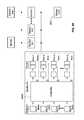
- a source 900 of pressurized hydraulic fluidtypically located on a tractor, supplies hydraulic fluid under pressure to an optional main valve 901 via a supply line 902 and receives returned fluid through a return line 903 .
- the main valve 901can be set by an electrical control signal S 1 on line 904 to deliver hydraulic fluid to an output line 905 at a desired constant pressure.
- the output line 905is connected to a manifold 906 that, in turn, delivers the pressurized hydraulic fluid to individual feed lines 907 (which are connected to ports of respective hydraulic cylinders of the individual row units).
- the main valve 901is turned off after all cylinders have been filled with pressurized hydraulic fluid to maintain a fixed volume of fluid in each cylinder.
- Each of the individual feed lines 907leads to one of the row units and is provided with a separate control valve 910 that receives its own separate control signal on a line 911 from a respective controller 912 (which is integrated in the respective row unit as described above in reference to FIGS. 24A and 30 ).
- the separate control valve 910is provided in addition to or instead of the valve 901 . This arrangement permits the supply of pressurized hydraulic fluid to each row unit to be turned off and on at different times by the separate control valve 910 for each row unit, with the times being controlled by the separate control signals supplied to the valves 910 by the respective controllers 912 .
- the individual valves 910receive pressurized hydraulic fluid via the manifold 906 , and return hydraulic fluid to the tractor via separate return lines 913 connected to a return manifold 914 , which is connected back to the hydraulic system 900 of the tractor.
- one or more of the individual integrated controllers 912are connected to a main controller 915 that provides control input for at least one of the integrated controllers 912 .
- the alternative configurationincludes a tractor 950 that generates hydraulic auxiliary power bifurcated into two power subsets: a tractor hydraulic system (THS) 952 and a tractor power take-off (PTO) 954 .
- the tractor hydraulic system 952is coupled to a hydraulically-driven electrical generator 956 for generating electricity for row unit components such as the control valves 910 and/or other control modules (e.g., controllers 912 , 915 ).
- the tractor PTO 954is mechanical power that runs a hydraulic pump 958 to provide mechanical power for row unit components such as hydraulic cylinders connected to the individual feed lines 907 .
- Providing both the hydraulic system 952 and the tractor PTO 954helps provide additional electrical power for electrical components that previously were not included in an agricultural system. For example, adding controllers 912 , 915 and control valves 910 to each row unit results in an increased need of electrical power relative to agricultural systems that, for example, lacked individual row-unit control.
- the electrical generator 956compensates for and provides the required increased electricity.
- a hydraulic cylinder systemincludes two hydraulic cylinders 1019 a , 1019 b , instead of a single actuator as described above in reference to the hydraulic cylinder 19 (which is illustrated, for example, in FIG. 9 ).
- Each of the hydraulic cylinders 1019 a , 1019 bis generally similar to the hydraulic cylinder 19 .
- this alternative embodimentillustrates coupling the two hydraulic cylinders 1019 a , 1019 b between a front frame 1014 and a linkage assembly 1015 .
- the hydraulic cylinders 1019 a , 1019 bare both mounted at one end to a cross bar 1030 , which has been modified in this illustrative embodiment and relative to the cross bar 30 of FIG. 9 to have generally a Z-shape. Specifically, a first hydraulic cylinder 1019 a is mounted such that it can apply down pressure D to the row unit and a second hydraulic cylinder 1019 b is mounted such that it can apply up pressure U to the row unit.
- the row unitcan be controlled both up and down with more precision.
- the controlled row unitmay have a heavy weight that results in a furrow depth exceeding the desired planting depth.
- the second hydraulic cylinder 1019 bis used to raise the row unit such that the shallower depth is achieved.
- the second hydraulic cylinder 1019 bacts to subtract (or counter) at least some of the row-unit weight.
- the first hydraulic cylinder 1019 ais used to lower the row unit such that the deeper depth is achieved. As such, the first hydraulic cylinder 1019 a acts to artificially add weight to the row unit.
- a hydraulic cylinder 1119includes two storage energy devices, which are illustrated in the form of a first accumulator 1127 a and a second accumulator 1127 b .
- Each of the two accumulators 1127 a , 1127 bis generally similar to the accumulator 27 (illustrated, for example, in FIG. 6 ).
- the hydraulic cylinder 1119includes a ram 1125 that acts similar to the double-acting ram 705 illustrated in FIGS. 28A and 28B .
- the ram 1125can provide both down pressure and up pressure, as needed, for a planting row unit (e.g., planting row unit 710 ).
- the accumulators 1127 a , 1127 bact as shock absorbers to help relieve pressure based on the direction of the applied pressure by the double-acting ram 1125 .
- the first accumulator 1127 arelieves pressure when the double-acting ram 1125 applies pressure in a first direction D 1 (e.g., down pressure)
- the second accumulator 1127 brelieves pressure when the double-acting ram 1125 applies pressure in a second direction D 2 (e.g., up pressure).
- this hydraulic cylinder 1119as a compact hydraulic down-force unit with integral accumulators 1127 a , 1127 b on each row unit, provides the advantages of quick response and remote adjustability of a hydraulic down-force and up-force control system. If an obstruction requires quick movement, oil can flow quickly and freely between the force cylinder 1119 and the respective adjacent accumulator 1127 a , 1127 b , without exerting force on other actuators in the system.
- a controllable hydraulic control system 1200includes a plurality of row units 1202 that are towed by a vehicle 1204 through a field.
- Each of the row units 1202includes a status indicator 1206 for signaling performance-related issues.
- the status indicators 1206are light-emitting diodes (LED) that provide an easily discernable way to visually inspect the performance of the row units 1202 .
- the LED status indicators 1206can flash a red color R to indicate improper tilling or a malfunction. If everything performs as intended, the status indicators 1206 can flash a green color G.
- the status indicator 1206can be a single (larger) LED or a plurality of LEDs of various sizes. Alternatively, the status indicator 1206 can include in addition to or instead of the LED an audible indicator to signal a malfunction or other condition of the system 1200 .
- the status indicators 1206can be integrated with control electronics of the row units 1202 (e.g., control module 525 illustrated in FIG. 23 ) and can provide a status-check of the electronics.
- the status indicators 1206are attached to each individual row unit 1202 to provide a person that is far away from the row units 1202 a quick visual check on the performance status of the system 1200 , including the performance status of an electronic controller.
- the status indicators 1206are particularly helpful in a system 1200 that is a human-less farming system.
- the human-less farming systemis a system in which robotic machines are moving about in the field to perform tilling, planting, and/or other agricultural functions. Such a system is monitored by a farm manager that is standing, for example, a quarter-mile away from the system.
- the status indicators 1206provide the farm manager with quick and easy visual signals that indicate the performance of the system.
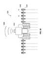
- the system 1200further emits a wireless signal 1208 for communicating status performance to an online monitoring system.
- the performance of the system 1200can be, then, evaluated using an electronic device such as a smartphone.
- an agricultural system 2100includes a soil-hardness sensing device 2102 attached in front of an agricultural row unit 2104 (also referred to as a planting row unit) via a towing frame 2106 .
- the towing frame 2106is generally a common elongated hollow frame that is typically hitched to a tractor by a draw bar.
- the towing frame 2106is rigidly attached to a front frame 2108 of a four-bar linkage assembly 2110 that is part of the row unit 2104 .
- the four-bar (sometimes referred to as “parallel-bar”) linkage assembly 2110is a conventional and well known linkage used in agricultural implements to permit the raising and lowering of tools attached thereto.
- a pair of cooperating toothed clearing wheels 2122clear residue from the soil and then other portions of the row unit, such as a V-opener disk 2112 , part the cleared soil to form a seed slot, deposit seed in the seed slot and fertilizer adjacent to the seed slot, and close the seed slot by distributing loosened soil into the seed slot with a pair of closing wheels 2114 .
- the closing wheels 2114are CUVERTINETM closing wheels sold by the assignee of the present application.
- the CUVERTINETM closing wheelis an efficient toothed wheel in-between a spading wheel and a rubber wheel.
- a gauge wheel 2116 of the planting row unit 2104determines the planting depth for the seed and the height of introduction of fertilizer, etc.
- One or more bins 2118 on the planting row unit 2104carry the chemicals and seed that are directed into the soil.
- the planting row unit 2104is urged downwardly against the soil by its own weight.
- a hydraulic or pneumatic actuator 2120(and/or one or more springs) is added between the front frame 2108 and the four-bar linkage assembly 2110 to urge the planting row unit 2104 downwardly with a controllable force.
- a hydraulic actuator 2120may also be used to lift the row unit off the ground for transport by a heavier, stronger, fixed-height frame that is also used to transport large quantities of fertilizer for application via multiple residue-clearing and tillage row units.
- the hydraulic actuator 2120is an RFXTM system sold by the assignee of the present application.
- the RFXTM systemincludes a down-pressure actuator that is a compact, fast action actuator, and that is remotely controlled.
- the RFXTM systemincludes a nitrogen pressure-vessel that is integrated with the down-pressure actuator.
- the hydraulic or pneumatic actuator 2120may be controlled to adjust the downward force for different soil conditions such as is described in U.S. Pat. Nos. 5,709,271, 5,685,245 and 5,479,992.
- the planting row unit 2104further includes a row-clearing unit 2122 having a pair of rigid arms 2124 adapted to be rigidly connected to the towing frame 2106 .
- the row-clearing unit 2122is a GFXTM system (i.e., ground effects row cleaner), which is sold by the assignee of the present application, that is a hydraulically-controlled row cleaner.
- the GFXTM systemis a hydraulically-controlled row cleaner with spring upward pressure and hydraulic down pressure. Furthermore, the GFXTM system is remotely adjusted.
- the pair of cooperating toothed clearing wheels 2126are positioned in front of the V-opener 2112 of the planting row unit 2104 .
- the clearing wheels 2126are arranged for rotation about transverse axes and are driven by engagement with the underlying soil as the wheels are advanced over the soil.
- the illustrative clearing wheels 2126are a type currently sold by the assignee of the present invention under the trademark TRASHWHEELTM.
- TRASHWHEELTMThe clearing wheels 2126 cooperate to produce a scissors action that breaks up compacted soil and simultaneously clears residue out of the path of planting.
- the clearing wheels 2126kick residue off to opposite sides, thus clearing a row for planting. To this end, the lower edges are tilted outwardly to assist in clearing the row to be planted. This arrangement is particularly well suited for strip tilling, where the strip cleared for planting is typically only about 10 inches of the 30-inch center-to-center spacing between planting rows.
- the soil-hardness sensing device 2102has a first linkage 2130 with an attached blade 2132 and a second linkage 2134 with an attached gauge wheel 2136 .
- the linkagesare medium FREEFARMTM linkages sold by the assignee of the present application.
- the FREEFARMTM linkagesare generally modular sets of parallel linkages used for different purposes.
- the soil-hardness sensing device 2102is a FORESIGHT AND CFXTM ground hardness sensor that is sold by the assignee of the present application.
- the two linkages 2130 , 2134are parallel to each other and each has a down hydraulic pressure that is controlled independently. Under constant hydraulic pressure, when the soil-hardness sensing device 2102 is moved through the field, the blade 2132 penetrates the soil deeper in soft soil and shallower in hard soil. However, the wheel 2136 rides on the soil surface regardless of the type of soil.
- Each linkage 2130 , 2134has a high quality all-stainless steel linear position sensor 2138 , 2140 enclosed in a protecting housing, with a cable 2142 , 2144 routed to a central processing unit (CPU) 2146 , which includes a memory device for storing instructions and at least one processor for executing the instructions.
- CPUcentral processing unit
- the two values from the position sensors 2138 , 2140are outputted as fast as approximately 1,000 times/second and are fed as soil-hardness signals to the CPU 2146 , which is a rugged outdoor-rated programmable logic controller that measures the difference in the two values in real time.
- the CPU 2146is positioned on the planting row unit 2104 .
- the CPU 2146may be positioned remote from the planting row unit 2104 , e.g., in a tractor cabin, on a different planting row unit of a side-by-side row unit arrangement, etc.
- the processor and the memory device of the CPU 2146can be located in the same place, e.g., on the planting row unit 2104 , or in different places, e.g., the processor can be located on the planting row unit 2104 and the memory device can be located in the tractor cabin.
- the CPU 2146averages the values over a predetermined time period (e.g., 0.25 seconds), executes an algorithm with filtering effects (e.g., removes conditions in which a rock is hit by the soil-hardness sensing device 2102 ), and provides real-time measurement of the soil hardness.
- the CPU 2146optionally receives other user-controllable variables for adjusting/tuning the agricultural system 2100 .
- the user-controllable variablesmay include values for different residue levels, different initial conditions, etc.
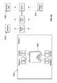
- the agricultural system 2100receives hydraulic fluid from a hydraulic source, typically located in the tractor, at a hydraulic input pressure P 0 .
- the hydraulic fluidis directed to each one of a plurality of hydraulic control valves V 1 -V 3 .
- the CPU 2146outputs respective signals S 1 -S 3 to the respective control valves V 1 -V 3 , which create a proportional output/change in the pressure of hydraulic circuits, virtually instantaneously changing the pressure in real time as the agricultural system 2100 moves through a field.
- the pressure changesare useful, for example, when the agricultural system 2100 encounters hardened soil areas in which combines or grain carts have previously compacted the soil.
- the agricultural system 2100optimizes the pressure to achieve a desired depth control by applying the right amount of pressure at the right time.
- the CPU 2146outputs the respective signals S 1 -S 3 to the associated control valves V 1 -V 3 .
- a first control valve V 1outputs a proportional first pressure P 1 to the hydraulic actuator 2120 (e.g., RFXTM system) for urging the planting row unit 2104 downwardly.
- a second control valve V 2outputs a proportional second pressure P 2 to the row-clearing unit 2122 (e.g., GFXTM system).
- the RFXTM system 2120 and the GFXTM system 2122are controlled independently because residue typically exhibits non-linear behavior. In other words, the independent control of the two systems 2120 , 2122 is likely to achieve better depth-control results.
- a third control valve V 3receives a third signal S 3 from the CPU 2145 , in response to which the third control valve outputs a proportional third pressure P 3 to the soil-hardness sensing device 2102 (e.g., FORESIGHT AND CFXTM system).
- the control valves V 1 -V 3return hydraulic fluid to the hydraulic source at a return pressure PR.
- Respective transducers for each of the control valves V 1 -V 3may be used to verify that hydraulic output pressures match the desired values. If a hydraulic output pressure does not match the desired value, the hydraulic output pressure is corrected.
- each of the control valves V 1 -V 3has a respective valve response time T 1 -T 3 , as discussed in more detail below in reference to determining the timing of applying the appropriate pressures P 1 -P 3 .
- the CPU 2146further receives an input speed signal SQ indicative of a speed Q of the agricultural system 2100 , which moves typically at about 6 miles per hour, i.e., about 8.8 feet per second. As discussed in more detail below, the speed signal SQ is used to determine the desired values of pressures P 1 -P 3 based on current soil conditions. Furthermore, as discussed in more detail below, the CPU 2146 further outputs two signals, a sensor signal SCFX to the soil-hardness sensing device 2102 and a closing wheel signal SCW to the closing wheel 2114 .
- Dis a known distance (e.g., the distance between the sensed position and position where seed-depositing position) and the speed Q is also known, changes in soil conditions can be anticipated in real time prior to the time when each individual tool on the planter row unit 2104 arrives at any particular soil-change area. For example, assuming that Q is approximately 8.8 feet per second and T is approximately 0.25 seconds, D should be approximately equal to or greater than 2.2 feet. In other words, the minimum distance for D should be approximately 2.2 feet. If D is greater than the minimum value (e.g., D is greater than 2.2 feet), the agricultural system 2100 is calibrated to account for the additional distance. For example, the CPU 2146 will send the respective signals S 1 , S 2 to the associated control valves V 1 , V 2 only after a predetermined period of time Tact, as discussed in more detail below.
- Tacta predetermined period of time
- a time variable Rrefers to the latent processing speed of CPU 2146 and accounts for the time between (a) receiving an input signal by the CPU 2146 , (b) sending output signals S 1 , S 2 by the CPU 2146 , and (c) responding to the output signals S 2 , S 2 by the control valves V 1 , V 2 with respective outputting pressures P 1 , P 2 .
- each of the control valves V 1 , V 2has a minimum input time Tmin, and that the distance D (e.g., as measured between the center of the blade 2232 and the center of the V-opener 2212 ) is directly proportional to the speed Q multiplied by the minimum input time Tmin of the respective control valve V 1 , V 2 .
- a theoretical time Ttheoris directly proportional to the distance D divided by the speed Q (i.e., D/Q), and that an actual time Tact is directly proportional to the theoretical time Ttheor minus the time variable R (i.e., Ttheor ⁇ R).
- the CPU 146Based on these conditions, for outputting pressures P 1 and P 2 , the CPU 146 holds in memory output signals S 1 and S 2 for a time duration that is equal to the actual time Tact. After the actual time Tact has elapsed, the CPU 146 outputs signals S 1 and S 2 , respectively, to the control valves V 1 , V 2 , which respond by outputting pressures P 1 , P 2 .
- signals S 1 and S 2are outputted as signals ranging between 0-10 volts.
- a global positioning systemprovides a GPS signal indicative of the speed Q to the tractor.
- the speed Qcan be generated from a radar system.
- the speed Qis inputted to the CPU 2146 , along with the soil-hardness signals received from the position sensors 2138 , 2140 .
- the CPU 2146Based on the speed Q and the soil-hardness signals, the CPU 2146 outputs signals S 1 and S 2 to the control valves V 1 , V 2 , which output proportional pressures P 1 and P 2 for adjusting, respectively, the RFXTM system 2120 and the GFXTM system 2122 .
- the agricultural system 2100encounters various types of soil-hardness conditions, which, for ease of understanding, will include soft soil conditions and hard soil conditions.
- the soft soil conditionsexemplify typical soil conditions
- the hard soil conditionsexemplify compacted soil areas, e.g., areas compacted by tire tracks of tractors or combines.
- the agricultural system 2100is moving forward at a speed Q over an initial soil area having only soft soil conditions. Based on the soft soil, the blade 2132 penetrates the soil at a distance X 1 lower than the wheel 2136 (which rides on the soil surface). The distance X 1 is the difference between the position sensors 2138 , 2140 . In accordance with the distance X 1 , which is associated with soft soil conditions, corresponding pressures P 1 and P 2 are applied to the hydraulic actuator 2120 and the row-clearing unit 2122 .
- the blade 2132 and the wheel 2136are now moving over a soil area of hard soil conditions. Because the soil is now much harder than the previous soil area, the blade 2132 cannot penetrate the soil as much as in the previous soil area. As such, the blade 2132 rises higher relative to the soil surface and penetrates the soil only at a distance X 2 lower than the wheel 2136 (which continues to ride on the soil surface).
- the distance X 2is the distance determined by the CPU 2146 based on the corresponding change in values outputted by the position sensors 2138 , 2140 .
- the planting row unit 2104is now moving over the hard-soil area, which the blade 2132 and the wheel 136 have already passed.
- the pressures P 1 and P 2are increased to maintain the desired depth level.
- the soil-hardness sensing device 2102has reached, again, soft soil conditions that allow the blade 2132 to penetrate the soil at the previous distance X 1 , the pressures P 1 and P 2 are adjusted in accordance with the hard soil conditions.
- FIG. 40Aanother exemplary soil-hardness sensing device 2202 is attached to a towing frame 2206 which in turn is attached to a planting row unit 2204 having a V-opener disk 2212 , a pair of closing wheels 2214 , and a row-unit gauge wheel 2216 .
- the planting row unit 2204further includes a hydraulic actuator 2220 that responds to a pressure P 1 and a row-clearing-unit actuator 2222 that responds to a pressure P 2 .
- the soil-hardness device 2202 and the planting row unit 2204are generally similar to the soil-hardness device 2102 and the planting row unit 2104 described above in reference to FIGS. 1-4C , except for any changes described below.
- the soil-hardness device 2202can be a device that is already included in the planting row unit 2204 , such as a cutting coulter running directly in-line with the planter row unit or a fertilizer opener positioned off to a side of the planted area.
- the soil-hardness devicecan include a fertilizer opener or a no-till cutting coulter in front of every row unit.
- the soil-hardness device 2202includes a blade 2232 and a soil-hardness gauge wheel 2236 .
- the blade 2232is attached to a blade arm 2260
- the soil-hardness gauge wheel 2236is attached to a wheel arm 2262 .
- the wheel arm 2262is biased down by a spring 2264 and pivots relative to the blade arm 2260 .
- An angular encoder 2266measures changes in an angle ⁇ between the blade arm 2260 and the wheel arm 2262 .
- the angle ⁇is directly proportional to the depth of the blade 2232 relative to the soil-hardness gauge wheel 2236 .
- the angle ⁇is sent to a CPU 2246 which executes an algorithm to determine corresponding pressure values for the planting row unit 2204 .
- a minimum angle ⁇ minis equal to angle ⁇ when both the blade 2232 and the soil-hardness gauge wheel 2236 are on the soil surface, e.g., when passing over very hard soil conditions or a concrete floor.
- a depth variable Zindicates a desired blade depth, i.e., blade 2232 penetration into the soil.
- the angle ⁇is directly proportional to the depth variable Z, which has a range between an actual (or current) depth value Zact and a theoretical depth value Ztheor.
- a controllable pressure P 3which is applied to the soil-hardness device 2202 , is varied, but the angle ⁇ between the blade 2232 and the soil-hardness gauge wheel 2236 is maintained generally constant, with the blade 2232 penetrating the soil at a desired blade depth Z.
- the difference between the blade 2132 and the wheel 2136is varied (e.g., distances X 1 and X 2 ), but the pressure applied to the soil-hardness device 2102 is maintained generally constant.
- angle ⁇is less than minimum angle ⁇ min (i.e., ⁇ min)
- algorithmignores changes because those values typically illustrate that the soil-hardness sensing device 2202 has hit a rock.
- the desired depth Z of the blade 2232is maintained constant by varying the pressure P 3 in response to detected changes in the angle ⁇ .
- a user-defined variable M(similar to the user-defined variables K and J described below) is increased or decreased to modify an actual value P 3 act of the pressure P 3 until the desired depth variable Z is achieved.
- Mis modified until M*P 3 act is equal to P 3 theor (and, consequently, the desired depth variable Z is achieved).
- Mis increased until the actual pressure value P 3 act is equal to the theoretical value P 3 theor. Once the theoretical value P 3 theor is reached, the increased pressure forces the blade 2232 into the soil at the desired depth. Furthermore changes to the pressure P 1 and the pressure P 2 can be effected based on M*P 3 act being directly proportional to P 1 and P 2 .
- a weight variable Wis set in accordance with a desired weight.
- the pressure P 1 applied to the hydraulic actuator 2220 of the planting row unit 2204is directly proportional to a user-defined variable K multiplied by the pressure P 3 applied to the soil-hardness device 2202 (i.e., P 1 is directly proportional to K*P 3 ).
- a signal S 5(illustrated in FIG. 40A ), which is directly proportional to the weight variable W, is outputted by a gauge wheel load sensor 2280 (illustrated in FIG. 5A ) and averaged over a time period Tgauge.
- the user-defined variable Kcan be set manually by a user or automatically via a load pin 2282 .
- the pressure P 2 applied to the row-cleaner unit 2222can be adjusted by adjusting a user-defined variable J.
- the pressure P 2is directly proportional to the user-defined variable J multiplied by the pressure P 3 (i.e. P 2 is directly proportional to J*P 3 ).
- the user-defined variable Jcan also be set manually by a user or automatically via the load pin 282 .
- an agricultural system 2300includes a tractor 2301 , two soil-hardness sensing devices 2302 A, 2302 B, a planting device 2303 , and a plurality of planting row units 2304 A- 2304 L, which are configured in a side-by-side arrangement.
- each of the planting row units 2304 A- 2304 Lhas at least one respective control Valve A-L, which is adjustable based on signals received from the soil-hardness sensing devices 2302 A, 2302 B.
- the tractor 2301moves at a speed Q, pulling the soil-hardness sensing device 2302 A, 2302 B, the planting device 2303 , and the planting row units 2304 A- 2304 L along a soil area that includes five soil areas 2305 A- 2305 E.
- the soil areas 2305 A- 2305 Eincludes a right-side outside area 2305 A, a right-side wheel area 2305 B, a central area 2305 C, a left-side wheel area 2305 D, and a left-side outside area 2305 E.
- the right-side wheel area 2305 B and the left-side wheel area 2305 Dhave soil conditions that are harder than the right-side outside area 2305 A, the central area 2305 C, and the left-side outside area 305 E.
- each of the right-side wheel area 2305 B and the left-side wheel area 2305 Dare areas compacted by the wheels of vehicles.
- a first soil-hardness sensing device 2302 Acontrols only the planting row units 2304 E, 2304 H that are positioned inside the compacted paths of the right-side wheel area 2305 B and the left-side wheel area 2305 D.
- a second soil-hardness sensing device 2302 Bcontrols all the other planting row units 2304 A- 2304 D, 2304 F- 2304 G, and 2304 I- 2304 L, i.e., all the planting row units positioned outside the compact paths of the right-side wheel area 2305 B and the left-side wheel area 2305 D (and within the right-side outside area 305 B, the central area 2305 C, and the left-side outside area 2305 E).
- any number of soil-hardness sensing devices and any number of planting row unitscan be used.
- each of the planting row units 2304 A- 2304 Lcan have its own designated soil-hardness sensing device.
- the soil-hardness sensing devices 2302 A, 2302 Bare positioned at a distance D in front of the planting row units 2304 A- 2304 L.
- each of the soil-hardness sensing devices 2302 A, 2302 Bcan be positioned at a different distance in front of the planting row units 2304 A- 2304 L.
- the first soil-hardness sensing device 2302 Acan be positioned at a distance X 1 in front of the planting row units 2304 A- 2304 L and the second soil-hardness sensing device 2302 B can be positioned at a distance X 2 in front of the planting row units 2304 A- 2304 L.
- the distances X 1 and X 2are equal to each other (being effectively distance D). Furthermore, the first soil-hardness sensing device 2302 A is positioned inside the compacted path of the left-side wheel area 2305 D and the second soil-hardness sensing device 2302 B is positioned inside the left-side outside area 2305 E (i.e., outside the compacted path of the bottom wheel area 305 D).
- the soil-hardness sensing devices 2302 A, 2302 B and the attached planting row units 2304 A- 2304 Lare generally configured to sense soil conditions and adjust corresponding hydraulic pressures of Valves A-L as described above in reference to FIGS. 36-40 .
- the configuration of having multiple soil-hardness sensing devices 2302 A, 2302 Bincreases precision in adjustment of hydraulic pressures, based on current soil conditions, because it accounts for differences between compacted and non-compacted paths in a field that is being planted.
- the soil-hardness sensing devices 2302 A, 2302 Bprovides signals to corresponding control valves for increasing and/or decreasing hydraulic pressures of the planting row units 2304 A- 2304 L.
- the soil-hardness sensing devices discussed abovecan be remotely controlled.
- the soil-hardness sensing devices 2302 A, 2302 Bcan be remotely controlled with a handheld radio-frequency remote controller.
- the remote controllercan be used to manually increase and/or decrease the hydraulic pressures in one or more of the soil-hardness sensing devices 2302 A, 2302 B.
- the soil-hardness device 2202 illustrated in FIG. 40Ahas been modified to include modular actuators 2220 a - 2220 d .
- Each of the modular actuators 2220 a - 2220 dis identical (or nearly identical) to each other as a modular unit that allows the same unit to be used for movement of different components of the soil-hardness device 2202 .
- the modular actuators 2220 a - 2220 dinclude the hydraulic actuator 2220 described above and illustrated in FIG. 40A or the hydraulic actuator 2120 described above and illustrated in FIG. 36 .
- Each of the modular actuators 2220 a - 2220 dprovides controllable pressure for urging the respective components downwardly and/or upwardly, based on the mounting and type of actuator.
- the modular actuators 2220 a - 2220 dcan include a double-acting actuator in which the controllable pressure can be applied to urge the planting row 2104 , alternately, both upwards and downwards.
- a first modular actuator 2220 ais configured and mounted to apply a controllable downward force on the entire planting row unit 2204 attached to the rear side of the towing frame 2221 .
- a second one of the modular actuators 2220 bis configured and mounted to urge the blade 2232 with a controllable force.
- a third one of the modular actuators 2220 cis configured and mounted to urge the row-clearing unit 2222 with a controllable force.
- a fourth one of the modular actuators 2220 dis configured and mounted to urge the closing wheel 2214 with a controllable force.
- One exemplary benefit of having interchangeable actuators 2220 a - 2220 dis that a reduced number of spare parts is required for maintaining the system, thus, reducing cost.
- Another exemplary benefitis that a farmer or operator does not have to learn how to use and/or replace a separate and distinct type of actuator for each movable component. For example, knowing how to replace or maintain the first actuator 2220 a means that the farmer knows how to replace or maintain each of the other three actuators 2220 b - 2220 d . As such, the general result of having interchangeable actuators is reduced cost and a simpler system.
- any number of modular actuatorscan be adapted for mounting in any agricultural systems.
- the soil-hardness device 2202can include two modular actuators of a first type and two modular actuators of a second type.
- the first and second actuators 2220 a , 2220 bcan include a double-acting actuator for applying both upwards and downwards pressure
- the third and fourth actuators 2220 c , 2220 dcan include a single-acting actuator for applying either upward or downward pressure.
- the modular actuatorsare used in systems that lack soil-hardness sensing capabilities.
- an alternative modular unit 2400includes a mounting bracket 2402 attached to an upper support 2404 .
- a gauge arm 2406is pivotably attached at a proximal end 2407 to a swing arm 2408 , which is attached to the upper support 2404 .
- the gauge arm 2406is attached at a distal end 2409 to a gauge wheel 2410 , and the swing arm 2408 is further attached to a blade 2432 .
- the modular unit 2400includes a modular actuator 2420 that is removably attached to the upper support 2404 at a fixed end 2422 and to the swing arm 2408 at a movable piston end 2424 .
- the modular actuator 2420is illustrated in this exemplary embodiment as a pressure-applying device for the blade 2432 .
- the modular actuator 2420is removed by removing, for example, an assembly bolt 2426 and/or any other fastener holding the modular actuator 2420 in place relative to the upper support 2404 and the swing arm 2408 .
- the same modular actuator 2420(without the requirement for additional components) can be fastened to a different component of the soil-hardness device 2202 (e.g., the row-clearing unit 2222 ).
- a different component of the soil-hardness device 2202e.g., the row-clearing unit 2222 .
- the blade arm 2260has a distal end 2502 in which a ground-hardness sensor 2500 is integrated.
- the ground-hardness sensor 2500is fixed relative to the blade arm 2260 in a metallic cam 2501 that includes an aperture 2504 through which a rotating shaft 2506 protrudes.
- the rotating shaft 2506is coupled to the gauge wheel 2236 via the wheel arm 2262 .
- the gauge wheel 2236causes the shaft 2506 to rotate.
- the ground-hardness sensor 2500detects the rotational movement of the shaft 2506 within the aperture 2504 and provides output indicative of an angular change between the supporting arms for the gauge wheel 2236 and the blade 2232 .
- the ground-hardness sensor 2500also includes an indicator 2508 that is configured to indicate a performance condition.
- the indicator 2508is a light-emitting diode (LED) that displays a continuous green light when the ground-hardness sensor 2500 is functioning properly and a flashing red light when a malfunction occurs.
- LEDlight-emitting diode
- the ground-hardness sensor 2500is shielded from the environment with a cover 2510 , which is mounted to the distal end 2502 to enclose within the cam 2501 .
- the cover 2510consists of a translucent or transparent material, such as a clear plastic material, to readily allow visual inspection of the ground-hardness sensor 2500 .
- one benefit of the cover 2510is that an operator is not required to remove any parts to determine whether the ground-hardness sensor 500 is operating properly.
- the ground-hardness sensor 2500is provided in addition to or instead of the encoder 266 described above in reference to FIG. 40A . As described above, as the shaft 2506 rotates, the ground-hardness sensor 2500 measures changes in the angle ⁇ between the blade arm 2260 and the wheel arm 2262 to determine the depth Z of the blade 2232 relative to the soil-hardness gauge wheel 2236 . Then, the angle ⁇ is sent to the CPU 2246 for executing the algorithm to determine corresponding pressure values for the planting row unit 2204 . The angle ⁇ is directly proportional to the depth of the blade 2232 relative to the soil-hardness gauge wheel 2236 .
- the ground-hardness sensor 2500can be any analog or digital sensor that is capable of measuring an angular displacement.
- the ground-hardness sensor 2500can be a linear inductive distance sensor, which is an analog device.
- the blade arm 2260further includes a torsion spring 2512 that engages the shaft 2506 to rotationally bias the shaft 2506 toward an equilibrium point when the shaft 2506 applies a rotational force.
- the torsion spring 2512can be attached instead of or in addition to the spring 2264 illustrated in FIG. 40A .
- the torsion spring 2512is a compressive, rubber spring with adjustable down-pressure.
- the torsion spring 2512is in the form of an external structure 2512 a in which an internal structure 2512 b is positioned.
- the external and internal structures 2512 a , 2512 bare generally rectangular and are concentrically aligned along a central axis.
- the internal structure 2512 bis offset at an angle of about 90 degrees relative to the external structure 2512 a .
- a first directione.g., counterclockwise
- the internal structure 2512 bmoves with the shaft 2506 such that corners of the internal structure 2512 b tend to align with corners of the external structure 2512 a .
- the external structure 2512 aapplies a second, opposing force (e.g., clockwise) that counters the first direction and forces the internal structure 2512 b and the shaft 2506 back towards the equilibrium point.
- the torsion spring 2512compresses to dampen the effects of the rotational force of the shaft 2506 .
- the compressionprovides a smoother change in movement for the blade arm 2260 , and increases the torsion spring 2512 resistance to fatigue.
- torsion spring 2512is protected from environmental conditions, including dirt or mud, that can potentially interfere with the applied compressive force. Yet another benefit of the torsion spring 2512 is that it reduces the number of exposed components, which can be a hazard to human operators.
- FIGS. 44C-44Gillustrate an application of soil hardness sensing for controlling the down pressure on a pair of closing wheels 2551 journaled on a support arm 2553 having an upper end that pivots around a horizontal axis 2554 .
- a ground gauge wheel 2555is journaled on a support arm 2556 having an upper end that pivots around the same horizontal axis 2554 as the support arm 2553 .
- the ground gauge wheel 2555rolls along the surface of the soil with little variation in its vertical position relative to the soil surface, because of the wide and smooth surface area of the wheel 2555 .
- the closing wheels 2551penetrate into the soil, and thus change their vertical positions according to the hardness of the soil.
- the resulting pivoting movement of the support arm 2553is thus representative of the soil hardness.
- This relative pivoting movement of the support arm 2553is measured by an angular measurement device 2560 coupled to the upper end of the support area 2553 .
- the angular measurement device 2560is formed by the combination of (1) a cam 2561 attached to a stub shaft 2561 a projecting laterally from the support arm 2553 and (2) an adjacent inductive proximity sensor 2562 .
- the support arm 2553pivots around the axis 2554
- the corresponding angular movement of the cam 2561is detected by the sensor 2562 , which produces an electrical output signal that is proportional to the distance between the surface of the arm 2561 and the adjacent and of the sensor 2562 .
- the output signal produced by the sensor 2562is proportional to the angular position of the support arm 2853 , which in turn is generally proportional to the soil hardness.
- This signalcan be used to regulate the down pressure exerted on the closing wheels 2551 , by the hydraulic actuator 2563 , to compensate for variations in the sensed soil hardness.
- FIG. 45is a schematic diagram of a hydraulic control system for any or all of the hydraulic actuators in the systems described above.
- the hydraulic cylinder 2600is supplied with pressurized hydraulic fluid from a source 2601 via a first controllable two-position control valve 2602 , a restriction 2603 and a check valve 2604 .
- the pressurized hydraulic fluid supplied to the cylinder 2600can be returned from the cylinder to a sump 2605 via a second controllable two-position control valve 2606 , a restriction 2607 and a check valve 2608 .
- Both the control valves 2602 and 2606are normally closed, but can be opened by energizing respective actuators 2609 and 2610 , such as solenoids.
- Electrical signals for energizing the actuators 2609 and 2610are supplied to the respective actuators via lines 2611 and 2612 from a controller 2613 , which in turn may be controlled by a central processor 2614 .
- the controller 2613receives input signals from a plurality of sensors, which in the example of FIG. 45 includes a pressure transducer 2615 coupled to the hydraulic cylinder 2600 via line 2616 , and a ground hardness sensor 2617 .
- An accumulator 2618is also coupled to the hydraulic cylinder 2600 , as described in detail above, and a relief valve 2619 connects the hydraulic cylinder 2600 to the sump 2605 in response to an increase in the pressure in the cylinder 2600 above a predetermined level.
- control valves 2602 and 2606are preferably controlled with a pulse width modulation (PWM) control system implemented in the controller 2613 .
- PWMpulse width modulation
- the PWM control systemsupplies short-duration (e.g., in the range of 50 milliseconds to 2 seconds with orifice sizes in the range of 0.020 to 0.2 inch) pulses to the actuators 2609 and 2610 of the respective control valves 2602 and 2606 to open the respective valves for short intervals corresponding to the widths of the PWM pulses. This significantly reduces the energy required to increase or decrease the pressure in the hydraulic cylinder 2600 .
- the pressure on the exit side of the control valveis determined by the widths of the individual pulses and the number of pulses supplied to the control valves 2602 and 2606 .
- the pressure applied to the hydraulic cylinder 2622may be controlled by separately adjusting the two control valves 2602 and 2606 by changing the width and/or the frequency of the electrical pulses supplied to the respective actuators 2609 and 2610 , by the controller 2613 . This avoids the need for a constant supply current, which is a significant advantage when the only available power source is located on the tractor or other vehicle that propels the soil-engaging implement(s) across a field.
- the hydraulic control system of FIG. 45may be used to control multiple hydraulic cylinders on a single row unit or a group of row units, or may be replicated for each individual hydraulic cylinder on a row unit having multiple hydraulic cylinders.
- each hydraulic cylinder on any given row unitseparately controlled so that the down pressure on each tool can be adjusted according to the location of that tool in the direction of travel.
- the down pressure on each toolis preferably adjusted to accommodate the softer soil only during the time interval when that particular tool is traversing the wet area, and this time interval is different for each tool when the tools are spaced from each other in the direction of travel.
- the same hydraulic control systemmay control a group of valves having common functions on all the row units in a group.
- FIG. 46Ais a schematic diagram of a modified hydraulic control system that uses a single three-position control valve 2620 in place of the two two-position control valves and the two check valves used in the system of FIG. 45 .
- the centered position of the valve 2620is the closed position, which is the normal position of this valve.
- the valve 2620has two actuators 2620 a and 2620 b , one of which moves the valve to a first open position that connects a source 2621 of pressurized hydraulic fluid to a hydraulic cylinder 2622 via restriction 2620 c , and the other of which moves the valve to a second open position that connects the hydraulic cylinder 2622 to a sump 2623 .
- Electrical signals for energizing the actuators 2620 a and 2620 bare supplied to the respective actuators via lines 2624 and 2625 from a controller 2626 , which in turn may be controlled by a central processor 2627 .
- the controller 2626receives input signals from a pressure transducer 2628 coupled to the hydraulic cylinder 2622 via line 2629 , and from an auxiliary sensor 2630 , such as a ground hardness sensor.
- An accumulator 2631is coupled to the hydraulic cylinder 2622 , and a relief valve 2632 connects the hydraulic cylinder 2622 to the sump 2623 in response to an increase in the pressure in the cylinder 2622 above a predetermined level.
- a PWM control systemsupplies short-duration pulses P to the actuators 2620 a and 2620 b of the control valve 2620 to move the valve to either of its two open positions for short intervals corresponding to the widths of the PWM pulses. This significantly reduces the energy required to increase or decrease the pressure in the hydraulic cylinder 2622 .
- pulses P 1 -P 3having a voltage level V 1 , are supplied to the actuator 2620 b when it is desired to increase the hydraulic pressure supplied to the hydraulic cylinder 2622 .
- the first pulse P 1has a width T 1 which is shorter than the width of pulses P 2 and P 3 , so that the pressure increase is smaller than the increase that would be produced if P 1 had the same width as pulses P 2 and P 3 .
- Pulses P 4 -P 6which have a voltage level V 2 , are supplied to the actuator 2620 a when it is desired to decrease the hydraulic pressure supplied to the hydraulic cylinder 2622 .
- the first pulse P 4has a width that is shorter than the width T 2 of pulses P 2 and P 3 , so that the pressure decrease is smaller than the decrease that would be produced if P 4 had the same width as pulses P 5 and P 6 .
- FIG. 46Cillustrates an electrical control system that has a separate electrical controller 2651 , 2652 , 2653 . . . 2654 on each of multiple row units R 1 , R 2 , R 3 . . . Rn drawn by a single tractor T.
- the hydraulic actuators on each row unitcan be controlled independently of the actuators on the other row units.
- All the row unit controllers 2651 - 2654are controlled by a master controller 2650 , which may be located on the tractor or the draw bar, or even on one of the row units.
- the master controller 2650sends electrical signals to, and receives electrical signals from, each individual row unit in parallel, which provides significant advantages, especially when combined with the use of intermittent control signals such as the PWM signals discussed above.
- the master controllercan coordinate changes in pressure in the multiple row units sequentially, so that only a single row unit draws power from the source at any given time.
- each row unitcan signal the master controller when power is needed by that row unit, and then the master controller can control the supplying of power to only those row units requiring adjustment, and during the time interval when each row unit requires power for making adjustment. This reduces the time required to cycle through the row units to which power is sequentially supplied.
- the individual row unitscan send the master controller signals indicating the magnitude of adjustment required, and the master controller can assign higher priorities to those row units requiring the largest adjustments, so that those row units receive power for making adjustments more quickly than row units assigned lower priorities. Or the higher priority row units can be provided with power during more cycles than row units having lower priorities.
- a row-clearing unit 3010is mounted in front of a planting row unit 3011 .
- a common elongated hollow towing frame 3012(typically hitched to a tractor by a draw bar) is rigidly attached to the front frame 3013 of a four-bar linkage assembly 3014 that is part of the row unit 3011 .
- a coulter wheel 3015works the soil and then other portions of the row unit part the cleared soil to form a seed slot, deposit seed in the seed slot and fertilizer adjacent to the seed slot, and close the seed slot by distributing loosened soil into the seed slot with a closing wheel 3018 .
- a gauge wheel 3019determines the planting depth for the seed and the height of introduction of fertilizer, etc.
- Bins 3016 and 3017 on the row unitcarry the chemicals and seed which are directed into the soil.
- the planting row unit 3011is urged downwardly against the soil by its own weight.
- a hydraulic or pneumatic cylinder and/or one or more springsmay be added between the front frame 3013 and the linkage 3014 to urge the row unit downwardly with a controllable force.
- a hydraulic cylindermay also be used to lift the row unit off the ground for transport by a heavier, stronger, fixed-height frame that is also used to transport large quantities of fertilizer for application via multiple residue-clearing and tillage row units.
- This hydraulic or pneumatic cylindermay be controlled to adjust the downward force for different soil conditions such as is described in U.S. Pat. Nos. 5,709,271, 5,685,245 and 5,479,992.
- the row-clearing unit 3010includes an attachment frame that includes a pair of rigid arms 3020 and 3021 adapted to be rigidly connected to the towing frame 3012 .
- the arms 3020 and 3021are bolted to opposite sides of the front frame 3013 of the row unit 3011 , which in turn is rigidly attached to the towing frame 3012 .
- An alternativeis to attach the row-clearing unit 3010 directly to the towing frame 3012 .
- a pair of cooperating toothed clearing wheels 3022 and 3023are positioned upstream of the coulter wheel 3015 of the planting row unit 3011 .
- the clearing wheels 4022 , 4023are arranged for rotation about transverse axes and are driven by the underlying soil as the wheels are advanced over the soil.
- the illustrative wheels 4022 , 4023are a type currently sold by the assignee of the present invention under the trademark TRASHWHEEL.
- TRASHWHEELThe toothed wheels 4022 , 4023 cooperate to produce a scissors action that breaks up compacted soil and simultaneously clears residue out of the path of planting.
- the wheels 4021 and 4022kick residue off to opposite sides, thus clearing a row for planting. To this end, the lower edges are tilted outwardly to assist in clearing the row to be planted. This arrangement is particularly well suited for strip tilling, where the strip cleared for planting is typically only about 4010 inches of the 4030-inch center-to-center spacing between planting rows.
- the clearing wheels 4022 and 4023are shown in two different vertical positions. Specifically, the wheels 4022 , 4023 are in a lower position in FIG. 1 , where the elevation of the soil is decreasing, than in FIG. 48 , where the soil elevation is increasing.
- the row-clearing unit 10is shown in more detail in FIGS. 49-55 .
- the two frame arms 4020 , 4021are interconnected by an arched crossbar 4024 that includes a pair of journals 4025 and 4026 for receiving the leading ends of a pair of laterally spaced support arms 4030 and 4031 .
- the support arms 4030 , 4031are thus pivotally suspended from the crossbar 4024 of the attachment frame, so that the trailing ends of the support arms 4030 , 4031 can be pivoted in an arc around a horizontal axis 4032 extending through the two journals 4025 , 4026 .
- the row-clearing wheels 4022 and 4023are mounted on the trailing ends of the support arms 4030 and 4031 , which are bolted or welded together. As can be seen in FIGS. 50-52 , the wheels 4022 , 4023 can be raised and lowered by pivoting the support arms 4030 , 4031 around the horizontal axis 4032 . The pivoting movement of the support arms 4030 , 4031 is controlled by a hydraulic cylinder 4070 connected between the fixed crossbar 4024 and the trailing ends of the support arms 4030 , 4031 .
- FIGS. 50-52show the support arms 4030 , 4031 , and thus the clearing wheels 4022 , 4023 , in progressively lower positions.
- the downward pressure applied to the support arms 4030 , 4031 to urge the clearing wheels 4022 , 4023 against the soilis also controlled by the hydraulic cylinder 4070 .
- the hydraulic cylinder 4070is shown in more detail in FIGS. 53-55 .
- Pressurized hydraulic fluid from the tractoris supplied by a hose (not shown) to a port 4071 that leads into an annular cavity 4072 surrounding a rod 4073 , and then on into an accumulator 4079 .
- the portis closed by a valve, as will be described in more detail below.
- the lower end of the annular cavity 4072is formed by a shoulder 4074 on the rod 4073 , so that the hydraulic pressure exerted by the hydraulic fluid on the surface of the shoulder 4074 urges the rod 4073 downwardly (as viewed in FIGS. 53-55 ), with a force determined by the pressure of the hydraulic fluid and the area of the exposed surface of the shoulder 4074 .
- the hydraulic fluidthus urges the rod 4073 in an advancing direction (see FIG. 54 ).
- the rod 4073When the rod 4073 is advanced outwardly from the cylinder 4070 , the rod pivots the support arms 4030 , 4031 downwardly, thereby lowering the clearing wheels 4022 , 4023 . Conversely, retracting movement of the rod 4073 pivots the support arms 4030 , 4031 upwardly, thereby raising the clearing wheels 4022 , 4023 .
- the accumulator 4079includes a diaphragm that divides the interior of the accumulator into a hydraulic-fluid chamber 4079 a and a gas-filled chamber 4079 b , e.g., filled with pressurized nitrogen.
- FIG. 53shows the rod 4073 in a position where the diaphragm is not deflected in either direction, indicating that the pressures exerted on opposite sides of the diaphragm are substantially equal.
- the hydraulic forcehas advanced the rod 4073 to its most advanced position, which occurs when the resistance offered by the soil to downward movement of the clearing wheels 4022 , 4023 is reduced (e.g., by softer soil or a depression in the soil).
- advancing movement of the rod 4073is limited by the “bottoming out” of a coil spring 4075 located between a flange 4076 attached to the inner end of the rod 4073 and a flange 4077 attached to the interior of the cylinder 4070 .
- the coil spring 4075is progressively compressed until it reaches its fully compressed condition illustrated in FIG. 54 , which prevents any further advancement of the rod 4073 .
- Advancing movement of the rod 4073also expands the size of the annular cavity 4072 (see FIG. 54 ), which causes the diaphragm 4078 in the accumulator 4079 to deflect to the position illustrated in FIG. 54 and reduce the amount of hydraulic fluid in the accumulator 4080 .
- the support arms 4030 , 4031 and the clearing wheels 4022 , 4023are pivoted to their lowermost positions relative to the row unit 4011 .
- the rod 4073has been withdrawn to its most retracted position, which can occur when the clearing wheels 4022 , 4023 encounter a rock or other obstruction, for example.
- the support arms 4030 , 4031 and the clearing wheels 4022 , 4023are pivoted to their uppermost positions relative to the row unit.
- retracting movement of the rod 4073is limited by engagement of a shoulder 4080 on the rod 4073 with a ring 4081 on the trailing end of the cylinder 4070 .
- the coil spring 4075is progressively expanded, as illustrated in FIG. 55 , but still applies a retracting bias to the rod 4073 .
- FIG. 56is a schematic of a hydraulic control system for supplying pressurized hydraulic fluid to the cylinders 4070 of multiple row units.
- a source 4100 of pressurized hydraulic fluidtypically located on a tractor, supplies hydraulic fluid under pressure to a pressure control valve 4101 via supply line 4102 and receives returned fluid through a return line 4103 .
- the pressure control valve 101can be set by an electrical control signal S 1 on line 4104 from a controller 4112 , to deliver hydraulic fluid to an output line 4105 at a desired pressure.
- the output line 4105is connected to a manifold 106 that in turn delivers the pressurized hydraulic fluid to individual feed lines 4107 a , 4107 b . . .
- the row unitsinclude respective pressure sensors 4108 a , 4108 b . . . 4108 n that monitor the forces on the tools to which the respective hydraulic cylinders are coupled, and the sensors produce electrical output signals that are fed back to the controller 4112 for use in determining a desired setting for the pressure control valve 4101 .
- FIG. 57is a schematic of a modified hydraulic control system that permits individual control of the supply of hydraulic fluid to the cylinder of each separate row unit. Portions of this system that are common to those of the system of FIG. 56 are identified by the same reference numbers. The difference in this system is that each of the individual feed lines 4107 a , 4107 b . . . 4107 n leading to the row units is provided with a separate pressure control valve 4110 a , 4110 b . . . 4110 n , respectively, that receives its own separate electrical control signal on one of a plurality of output lines 4011 a , 4011 b . . . 4111 c from an electrical controller 4112 .
- This arrangementpermits the supply of pressurized hydraulic fluid to each row unit to be controlled by the pressure control valve 110 for that row unit.
- the individual valves 4110 a , 4110 b . . . 4110 nreceive pressurized hydraulic fluid via the manifold 4116 and separate supply lines 4113 a , 4113 b . . . 4113 n , and return hydraulic fluid to a sump on the tractor via a return manifold 4114 connected back to the return line 4103 of the hydraulic system 4100 of the tractor.
- each row-clearing unitcan be controlled independently of every other row-clearing unit.
- the down pressure for each row unitcan be remotely adjustable from the cab of the tractor or other selected location. This permits very efficient operation of a wide planter or other agricultural machine in varying terrain without having to stop to make manual adjustment to a large number of row units, resulting in a reduction in the number of acres planted in a given time period.
- One of the most important factors in obtaining a maximum crop yieldis timely planting.
- each row-clearing unitor group of units
- the ability to quickly release all down force and let the row cleaner quickly risee.g., when approaching a wet spot in the field
- one row-clearing unitOn wide planters or other equipment, at times 90 feet wide or more and planting at 6 mph or more forward speed, one row-clearing unit must often rise or fall quickly to clear a rock or plant into an abrupt soil depression. Any resistance to quick movement results in either gouging of the soil or an uncleared portion of the field and reduced yield. With each row unit having its own separate control, the clearing wheels and the rod of the hydraulic cylinder can move quickly and with a nearly constant down force.
- each pressure sensoris preferably connected between the ram of each hydraulic actuator 4019 and the support member for the tool controlled by that ram.
- FIG. 58One such system is illustrated in FIG. 58 , in which a tractor hydraulic system 4100 supplies pressurized hydraulic fluid to multiple row units 4401 a , 4401 b . . . 4401 n .
- each row unitincludes three hydraulic cylinders 4402 , 4403 and 4404 , one for each of three tool support members 4405 , 4406 and 4407 , and the hydraulic fluid is supplied to each hydraulic cylinder through a separate pressure control valve 4408 , 4409 or 4410 via a supply manifold 4102 and a return manifold 4103 .
- a separate pressure sensor 4411 , 4412 or 4413e.g., a load cell or strain gauge
- the electrical output signals from all the pressure sensors 4411 - 4413are sent to a controller 4420 , which generates a separate control signal for each of the pressure control valves 4408 , 4409 and 4410 .
- each row unithas been identified by the same reference numerals used for those same components in the other row units, with the addition of the same distinguishing suffixes used for the row units.
- row unit 4401 athe three hydraulic cylinders have been designated 4402 a , 4403 a and 4404 a . Only three row units 4401 a , 401 b . . . 401 n are shown in FIG. 58 , but it will be understood that any number of row units may be used, and it is common practice to have a tractor pull many more than three row units, all of which are coupled to the hydraulic system of the single tractor.
- the controller 4420continuously monitors the electrical output signals from the pressure sensors 4411 - 4413 and uses those signals to produce a separate control signal for each of the valves 4408 - 4410 . These signals control the pressure control valves 4408 - 4410 to maintain desired hydraulic pressures in the respective hydraulic cylinders 4402 - 4404 of all the row units. Consequently, if different row units encounter different soil conditions, those conditions are sensed by the respective pressure sensors 4115 and the output signals produced by those sensors cause different hydraulic pressures to be supplied to the different row units, thereby compensating for the particular soil conditions encountered by the different row units.
- the controller 4420automatically adjusts the control signals supplied to the corresponding valves to increase the hydraulic pressure supplied to the hydraulic cylinders associated with those valves.
- the system of FIG. 58is capable of providing independent control of the down pressure on different tools, such as the clearing wheels and the closing wheels, on the same row unit.
- the controller 4420receives a separate input signal from the pressure sensor associated with each separate cylinder, and produces a separate control signal for each separate pressure control valve.
- the hydraulic pressure supplied to each separate hydraulic cylindermay be separately controlled, independently of all the other cylinders, whether on the same row unit or different row units.
- the controller 4420may be programmed to use different algorithms to determine how the hydraulic pressure supplied to any given cylinder is adjusted in response to changes in the signals from the pressure sensor for that cylinder. For example, the controller can simply convert the signal from a given pressure sensor into a proportional signal having a linear relationship with the sensor output signal, to produce a control signal that falls within a suitable range for controlling the corresponding pressure control valve (e.g., within a range of 0-10V). Alternatively, the conversion algorithm can apply a scaling factor or gain to the signal from the sensor as part of the conversion. Filters may also be employed in the conversion process, e.g., to ignore sensor signals above a first threshold value and/or below a second threshold value.
- the sensor output signalsmay also be averaged over a prescribed time period.
- the signal from each pressure sensormay be sampled at predetermined intervals and averaged over a prescribed time period, so that the control signal supplied to the pressure control valve associated with that sensor does not change abruptly in response to only a brief, temporary change in soil conditions.
- Certain parameters, such as scaling factors,can be made manually selectable to enable an operator selection to customize the behavior of one or more row units to suit personal preferences. Different “mappings” may also be provided to enable an operator to select predetermined sets of variables correlated to different conditions.
- FIGS. 59 and 60illustrate a load cell 4500 for sensing the pressure on a pair of clearing wheels 4022 and 4023 .
- the load cell 4500couples the rod of the hydraulic cylinder 4070 to the two arms 4030 and 4031 that carry the clearing wheels 4022 and 4023 , so that the load cell is subjected to the same forces as the clearing wheels.
- the load cell 4500extends through an annulus 4501 attached to the end of the cylinder rod, and the opposite ends of the load cell extend through closely fitting apertures in the arms 4030 and 4031 and are secured thereto by a pair of C clips 4502 and 4503 .
- the electrical output signal produced by the load cell on its output line 4504changes in proportion to changes in the exerted forces.
- the control system described abovemay utilize position sensors, pressure transducers, load sensors, biased mechanical switches, etc. to detect varying field conditions, and sends signals to a programmable logic controller.
- the controllerin turn analyzes and processes those signals into a corrected usable signal, to be output to a number of integral hydraulic, pneumatic, or electric actuators that control parameters such as the down force on different parts of each row unit.
- the information collected in the processis preferably also used for a remote interactive display and controller, or for the development of soil condition maps, for use in future field planning, and maintenance.
- mapping of in-field obstacleshas strong potential to supplement planning for field development and maintenance, such as the removal of obstacles in the field (e.g., rocks, fence posts, etc.), determining appropriate crop rotation, identifying trouble spots for soil erosion, identifying areas that may benefit from tiling, determining appropriate tillage practices, and determining application rates for fertilizers and pesticides.
- obstacles in the fielde.g., rocks, fence posts, etc.
- determining appropriate crop rotatione.g., determining appropriate crop rotation
- identifying trouble spots for soil erosione.g., identifying areas that may benefit from tiling, determining appropriate tillage practices, and determining application rates for fertilizers and pesticides.
- Row unit down forcecan be used to control both the depth of a seeding unit or other agricultural implement, and the compaction of soil from a depth-gauging member such as the gauge wheels on a row crop planter.
- Two important elements of this processare the ability to ensure that the ground-engaging element (e.g., the vee opener blade on a planter row unit) consistently runs at a uniform depth, and that in the process of achieving depth, the gauging element(s) does not excessively compact the ground.
- Compacted groundis known to inhibit the germination and emergence of row crop seeds, as well as the lateral root growth of a row crop seedling.
- Row cleaner down forcecan be used to control the height and load of a floating row cleaners, which are devices that stretch and deliver row crop residue around the path of a seeding implement, or other depth gauging member to ensure that the depth gauging member runs upon a consistent surface.
- Running on a consistent surfaceallows for more uniform depth of the ground-engaging member. In the case of a seeding machine, this promotes consistent depth of seed, which is known to boost yield potential.
- a controllable down forcecan be used to regulate both the depth of a ground-engaging element of a cutting disc, and compaction caused by an adjacent gauge wheel.
- consistent depth of fertilizeris known to those skilled in the art to promote ideal nutrient uptake in a row crop plant. Consistent depth can also allow for uniform soil coverage of fertilizer by a furrow-closing device. Uniform coverage can reduce fertilizer loss from surface runoff, and/or loss due to volatilization of nitrogen, and off gassing.
- Closing wheel down forcecan be used to regulate the depth on a furrow-closing device. Consistent, properly calibrated down pressure and depth on a furrow closing device on a seeding unit, or other ground engaging tool, can ensure soil coverage over the furrow without causing excess compaction, or blow-out. This is of particular importance in the placement of row crop seeds.
- the seedideally requires the furrow closer to press soil tight to the seed to promote germination, while allowing the surface to remain loose, so that the seedling can emerge with little resistance due to compaction, or crusting.
- a depth gauging element actuatoris any device that allows for remote adjustment of the depth-gauging element of a row crop tool.
- Gauging depthis a critical element of almost all row crop tools (seeding units, tillage tools, fertilizer coulters, etc.)
- gauge wheel settingsare of primary importance. Uniform depth of the seed is well known to significantly improve yield potential.
- a planting row unitis attachable to a towing frame for movement in a forward direction on a field having soil of varying hardness conditions.
- the planting row unitincludes an opener device forward of the towing frame for preparing the soil for receiving at least one of the fertilizer and the seeds.
- the opener deviceincludes a soil-hardness sensor for detecting changes in soil-hardness conditions and an opener blade for maintaining, in response to the changes, a substantially constant soil-penetration depth Z in the soil independent of the varying hardness conditions.
- a modular actuatoris mounted to the opener device for applying pressure to the opener blade.
- a system for integrated control over all onboard actuators on an agricultural implementis described here.
- Typical of a row crop toolare two primary elements, a ground-engaging component, and a depth-gauging component.
- the positions of the lowest elements of the individual componentsare necessarily unequal.
- the lowest element of the ground-engaging component/sis identified by the extent to which the engaged media (e.g., soil, crop residue) is being physically manipulated.
- the lowest element of the gauging componentregulates the extent to which the ground-engaging components manipulate the engaged media. Regulating the depth on a ground-engaging component is of primary interest.
- the chief sensing element of this systemis a position sensor.
- This sensormay be linear or angular in nature and, depending on the method, may be either an absolute or a relative displacement sensor.
- This sensormay also be a laser rangefinder, or ultra-sonic in nature.
- This measurementis the primary input to an onboard programmable controller.
- the physical device generating this primary inputmay be used on an auxiliary or add-on component, such as a leading furrow opener having both a ground-engaging member and a depth-gauging member fitted with a position sensor situated to measure the relative distance between the ground-engaging member support, and the depth-gauging member support.
- the devicemay also be located on the ground-engaging member and depth-gauging member of the primary tool, such as the vee-opener blades on a seeding unit.
- Supplementary sensorsmay be installed both as primary sensing units, as well as performance correction devices, on the primary tool and on auxiliary tools.
- position sensorsmay be installed on a leading furrow opener, on a residue-managing device, on the seeding row unit, and on the furrow closer.
- operatorsmay choose only one or two position sensors as their primary signals, with the additional sensor(s) only positively contributing to error correction over the entire device.
- all four inputsare utilized for analyzing a row unit, and auxiliary tool position, and outputting a signal to all actuators that re-position the tool, or auxiliary components, to allow for maximum performance from the tool and its auxiliary components.
- the chief sensing elementis an integrated pressure transducer.
- Supplemental performance measurementsmay include load sensors (which are pre-installed on many ground-engaging tools) or biased proximity switches. These sensors may be used to correct errors that occur in the processing of the position sensor signal, and to verify that the actuators are performing properly.
- load sensorswhich are pre-installed on many ground-engaging tools
- biased proximity switchesThese sensors may be used to correct errors that occur in the processing of the position sensor signal, and to verify that the actuators are performing properly.
- many seeding unitsare equipped with “load pins” on the upper stops of the units' gauge wheels. Such load pins can generate signals that correlate directly to the signals generated by the position sensors.
- the multi-channel controller in this systemreceives the input signal of the position sensor of the primary ground-engaging tool, and any additional auxiliary signals, and then processes those signals to generate a base signal that is output to the actuators.
- This signalmay be processed using a number of mathematical methods to output a signal best suited for proper response from a particular actuator. After the signal is processed, it is checked and corrected using the signals from pressure transducers, load sensors or biased proximity switches. For example, in a seeding unit that is equipped with an actuated furrow opener, an actuated residue manager, a row unit down force actuator, and an actuated closing wheel, the primary signal is received from the furrow-opener position sensor. This signal is supplied to a controller that averages or otherwise mathematically manipulates the signal to produce a clean, consistent signal to each component's actuator. This signal typically differs for each actuator, and different computations are typically required for each output signal.
- the systemmay employ a vehicle bus to direct information to an in-cab monitor from the individual row controllers, where the information can be processed and viewed in a variety of different configurations.
- This informationmay also be delivered wirelessly to a remote location to alert an operator (e.g., via text messaging or e-mail) when errors occur with an actuator or any of its associated sensors.
- the preferred user interfaceis an interactive in-cab display having several features that allow the operator to quickly review all systems and adjust the appropriate actuator(s) accordingly.
- the displaymay provide row-by-row viewing of the functionality of individual tools and auxiliary components, or the functionality may be viewed over integrated sections, or by averages of units over a particular section.
- the interfacealso alerts the operator when any of the various actuators and/or sensors are malfunctioning, and signals which rows or sections need to be checked for repair, or calibration.
- controllersprocess and output signals. Due to the nature of the engaged media, the controller must sample the position of a particular tool, or component, and create a meaningful signal to be transmitted to the actuator. When in the field, row crop tools often encounter some relatively periodic oscillations due to ridges formed from a variety of pre-plant tools (tillage, fertilizer application, etc.). Additionally the position sensor will register large spikes as a result of encountering massive in-field obstacles (e.g., rocks, concrete, fence posts, etc.). Depending on location, the number of large spikes may be very frequent. The controllers must be able to register a wide variety of oscillations.
- the actuatorIn general, as ground hardness increases, the actuator must increase down force to push with more force against the hard ground. However, a massive, hard object like a rock requires a different approach. When encountering a massive object, increasing pressure on the actuators will greatly increase general wear on the row crop tool, potentially causing irreparable damage. Thus, when encountering massive objects, the controller preferably recognizes the immovable object and, whenever possible, reduces pressure on the row unit to avoid excessive wear on the tool.
- a forward velocity signal and a GPS coordinate signalmay simultaneously be gathered from the local CAN.
- This datacollectively can form a soil condition map of the field, identifying large stones or other obstacles that the operator can later efficiently remove by referring to the map. Additionally, when planning for tillage in a particular field, the operator may use the soil condition map to help identify areas that require more or less tillage.
- Rocks, clods, soil type, soil hardness, moisture level and other environmental factorscan affect the aperiodic oscillations of any ground-engaging tool sensor signals.
- the systemidentifies oscillations unique to a particular condition, or obstacle, using wave pattern recognition software.
- This data streamis synchronized with the GPS signal, and is used to develop a graphical representation of the field, providing a interactive map with GPS coordinate locations of soil compaction, excessive moisture, in-field obstacles such as rocks, or fence posts that the user may want to remove, or identify other conditions that, if treated, may boost soil fertility.
- This systemmay employ the input from any number of cameras, either section-by-section, or row-by-row.
- the implementation of visual surveillanceis for two primary purposes: visual verification of in-field obstacles for use with soil condition maps, and remote row unit inspection in the case of error signals.
- the controlleractivates a camera remotely to snap a still shot of the obstacle or condition of interest, or if the camera is generating video content, that data stream is time-stamped to easily synchronize with the video.
- the usermay then select an obstacle identified by the system as a signal of interest, and visually inspect the ground, to more easily determine if it is profitable to remove an obstacle or otherwise treat the soil.
- having the ability to visually inspect areas on an implement that has sensors detecting errorscan allow the operator to determine if the problem is critical and needs to be addressed, or if it can wait until the implement consumables are depleted and is stopped for reloading, or is otherwise down for maintenance.
- An additional function of the in-cab displayis to assist in controlling the depth-gauging member of the row crop tool.
- the ability to remotely control depthmay be of use to operators who are working in fields with widely varying conditions.
- the ability to slightly raise or lower the ground-engaging element of the toolcan be critical in some applications. Additionally, in wet conditions mud build-up on a depth-gauging member may cause erratic and uneven placement of a particular commodity (e.g., seed, fertilizer), which adversely affects yield potential.
- a particular commoditye.g., seed, fertilizer
- the systemmay include a photogate, sonogate, rangefinder or other sensor that directly determines the height of mud buildup on a gauge wheel. This may also be accomplished by using a sensor capable of determining the angular velocity of a wheel. As the radius on the wheel increases due to mud buildup, the angular velocity changes proportionally, and so may be used to adjust the depth setting to account for the additional radius of the gauge wheel. In either case, sensors determine the average displacement between the opener and the gauge wheel. If a change in relative displacement occurs, the system recognizes that change, and sends a signal to the gauge wheel actuator to make the appropriate adjustment, and maintain a set displacement.
- FIG. 61illustrates a complete system of tools that includes (1) a soil-hardness-sensing unit that includes a cutting disc 5001 , a gauge wheel 5001 a , a cutting disc position sensor 5002 , a cutting disc actuator 5003 , a cutting disc pressure transducer 5004 , a cutting disc load sensor/proximity switch 5005 ; (2) a controllably actuated row cleaner 5006 that includes a pair of cleaning wheels 5006 a and 5006 b , a row cleaner position sensor 5007 , a row cleaner actuator 5008 , a row cleaner pressure transducer 5009 , a row cleaner load sensor/proximity switch 5010 ; (3) a remotely actuated row unit that includes an actuator cradle 5011 , a row unit position sensor 5012 , a row unit actuator 5013 , a row unit pressure transducer 5014 , a row unit load sensor/proximity switch 5015 ; (4) a furrow-opening disc D and an adjacent gauge wheel
- the cutting disc actuator 5003receives a signal from the position sensor 5002 .
- This sensor's signalis the initial signal to be processed, corrected and then output to the various actuators 5003 , 5008 , 5013 and 5018 .
- some toolsmay be added or removed, but all have the same general configuration: sense position, adjust actuator, and verify or correct signal with load sensor or proximity switch.
- FIG. 62illustrates an exemplary algorithm for use in the system of FIG. 61 .
- the various sensor signalsare supplied to and processed by the row controller 5022 .
- the signals from the position sensors, the load sensors, and the pressure transducers of all the componentsare fed simultaneously into the row unit controller 5022 . This may include all the signals from all available sensors, or may utilize a smaller number of inputs if the demands of the operation do not require more advanced control over a particular operation.
- the controller 5022After all sensor signals are received, the controller 5022 generates output signals that produce any desired changes in the position and/or pressure of all the system actuators. Additionally, if available, the signals from the position sensors may be adjusted by employing the inputs from the pressure transducers, or the load sensors associated with the actuators.
- every rowis controlled individually by means of an output signal on a vehicle bus 5024 from the in-cab controller/monitor 5025 .
- “Row N” 5023is the nth row of a large platform seeding machine.
- Each of the N row unitshas an onboard controller 5022 coupled to the vehicle bus 5024 and a battery 5031 . All components may be monitored, and controlled from the in-cab interface.
- FIG. 63is an example of an algorithm similar to the algorithm of FIG. 62 , but in this case the row cleaner unit has been removed. Despite the lack of a row cleaner, a properly placed position sensor can still generate a usable signal. However, the more inputs, the more potential physical malfunctions may occur. In some instances, fewer inputs may lead to a slightly more trouble-free signal generation.
- FIG. 64is another example of a simplified algorithm.
- the cutting disc, and the row unitare outfitted with sensors, and actuators.
- This systemrequires much less computational power, and once again reduces the chance of potential problems that may arise from large numbers of sensors in a single row unit.
- FIG. 65illustrates a system that provides sectional control over row unit actuators.
- the signals of m row units in each of n sectionsare fed into a single controller on a master row unit X for that section. All the other row units in each section are slave units controlled by the controller 5040 —in the master row unit.
- the signals received by the controller 5040 on a master unitare combined to generate a separate output signal for each of the slave units' actuators.
- Each sectionthen has its own output that may be monitored and controlled from the in-cab interface.
- This sectional controlis another technique to reduce the overall cost of such a system. In many instances, field conditions over the width of a small number of rows change very little. In this case, the operator can still realize significant advantages utilizing sectional control.
- FIG. 66Ashows an in-cab interface when the implement is stationary
- FIG. 66Bshows an exemplary display when the implement is moving across a field.
- the implementhas five sections of row units.
- the display for each sectionincludes three columns, one for each of the three different actuators included in each row unit.
- the actuatorsare identified as “C” for a coulter, “G” for clearing wheels, and “R” for the row unit, and the bars in the respective columns represent the average performance of all the actuators of each of the three types in the row units in the identified section.
- the display for each columnis a vertical column of small horizontal bars. In FIG. 66A , none of the bars is illuminated because the implement is stationary. In FIG.
- the barsare depicted as illuminated uniformly but, as described in detail below, one of the bars in each column will be illuminated more brightly and with a color different from the other bars in that column, with the vertical position and color of that bar graphically indicating the average performance level of the corresponding tools in the row units in that particular section.
- a displayed numberrepresents the current average performance of the corresponding is in the row units in that particular section, where 100% performance represents sensor signals that cause the controller to produce an output signal that does not require any changes in the respective actuators for that type of tool in the row units in that particular section.
- the 98% at the top of column “C”means that the average value of the outputs of the actuators for the coulters in the three row units in Section 1 has been within 98% the respective target values for those actuators during the time interval used to compute the average value.
- the time interval used to compute the average valuesis typically a sliding window that is 2 to 5 minutes long, during about 120 to 300 sensor readings are taken for each actuator.
- FIG. 66Cdepicts an exemplary screenshot 6612 of a modified display on a video display 6610 in a monitor system 6600 for an agricultural machine such as an agricultural seed planter (e.g., a planting unit 10 , a fertilizer/opener unit, a strip-till cleaner unit, a full-width tillage unit, or any other agricultural machine for which a judgment about how much depth penetration of soil is needed or desired).
- the monitor system 6600includes a controller, such as the controller 112 , 2613 , 2626 , 4112 , 4420 , or the main controller 915 , central processor 2614 , 2627 or master controller 2650 , or any other controller or processor described herein.
- the controller used to control the displays shown in FIGS. 66A-66Eis a controller specially programmed with machine-readable instructions embodied in software and/or firmware to perform the row monitoring aspects described in connection with FIGS. 66A-66E .
- the row planting unit 10includes multiple row units, such as 16 in number.
- Each of the row unitshas a soil-engaging tool 2202 , such as a coulter (e.g., a fertilizer coulter) or V-opener or furrow-opening disk or coulter 11 , 711 , 800 , 2112 , 3015 (sometimes called CFXTM herein), a row cleaner 2122 , 2222 (sometimes called GFXTM herein), and/or a closing wheel 2114 , 2214 (sometimes called TFXTM herein).
- a coultere.g., a fertilizer coulter
- a row cleaner 2122 , 2222sometimes called GFXTM herein
- closing wheel 2114 , 2214sometimes called TFXTM herein
- Each of the row unitsalso includes one or more actuators (typically multiple actuators), such as any combination of a hydraulic actuator 2120 , 2220 that actuates the row unit, and one or more modular actuators 2420 which cause the soil-engaging tools 2202 , 2104 , 3015 , 2122 , 2114 to be urged toward earth (e.g., the soil) according to an actuator signal received from the controller.
- actuatorstypically multiple actuators
- the row unitpreferably has one actuator for each soil-engaging tool.
- a “soil-engaging tool”is a tool (or implement) that is configured to engage soil or earth under control of a control system.
- the planting row unititself includes one or more tools or implements, such as any combination of a coulter, a gauge wheel, a hardness sensor disk or wheel, and the like.
- Each “tool”is associated with at least one actuator that controls the one or more tools mechanically coupled to that actuator.
- the row unit itself(whether it is a planter type, a fertilizer type, a strip-till cleaner, a full-width tillage type, etc.) can be considered a tool or implement, such as when it has a gauge wheel or a coulter or the like attached to it.
- each toolcan be independently actuated by its own respective actuator, and the graphical user interfaces shown and described herein enable the operator to separately monitor at least one measurable parameter for each such tool on the row unit.
- the graphical user interfaces shown and described hereinenable the operator to separately monitor at least one measurable parameter for each such tool on the row unit.
- Each of the row unitsincludes one or more sensors, such as the position or ground-hardness sensors, pressure sensors, load cells or strain gauges described above. Each sensor measures a parameter related to or indicative of the force or pressure exerted on the mechanism associated with one of the actuators or the position of that mechanism. Each sensor provides an electrical signal indicative of the measured parameter to the controller.
- the measured parametercan be a force or pressure, or a position related to a distance traveled by the soil-engaging tool, such as a depth of soil penetration by the soil-engaging tool.
- the measured parametercan be a position related to a distance into the soil penetrated by the soil-engaging tool, e.g., the position can include an angular displacement or distance (e.g., height relative to earth) between the soil-engaging tool, on one hand, and ground or a reference structure on the row planting unit 10 , on the other hand.
- the sensoris a pressure sensor
- the parametercan be a force or a pressure. Force and pressure are related quantities, so these terms are used interchangeably herein.
- any number of sensorscan monitor multiple parameters relating to the soil-engaging tool, such as soil hardness of the soil engaged by the tool, soil moisture, downforce on the tool, load on the tool, vertical position of the tool relative to the surface of the soil, angular position of the tool relative to a fixed reference structure, pressure on the tool, geographic location or position of the tool (e.g., GPS coordinates), and the like.
- the video display 6610is coupled to the controller, which executes machine-readable instructions stored on one or more non-transitory storage media.
- the machine-readable instructionscan be implemented as firmware or software or both and stored on the one or more non-transitory storage media.
- the controllercauses the video display 6610 to display graphical elements thereon, and a conventional touch-sensitive interface (not shown) can be coupled to or integral with the video display 6610 to receive human inputs corresponding to selections of selectable elements displayed on the video display 6610 .
- a conventional touch-sensitive interface(not shown) can be coupled to or integral with the video display 6610 to receive human inputs corresponding to selections of selectable elements displayed on the video display 6610 .
- the video display 6610displays in real time as the row units are moved along the earth, row monitor graphical representations 6620 , 6630 , 6640 that indicate deviations of measured values from target values for different actuators on each of the 16 row units.
- the planting row unitpreferably maintains a consistent soil depth penetration across the field being planted so that the seeds are planted a consistent depth into the soil, e.g., 3 inches, depending on the crop being planted.
- the measured valuescan be ultimately related to actual soil penetration depths as measured by the sensor(s), and the target values are related to a desired soil penetration depth as a function of the crop being planted.
- the measured valuecan correspond to Z ACT , described above in connection with FIGS. 40A and 40B
- the target valuecan correspond to Z THEOR , described above in connection with FIGS. 40A and 40B .
- Section 1there are sixteen row units grouped into three sections, labeled Section 1 , Section 2 , and Section 3 , respectively, though any other textual or graphical label can be used to indicate the different sections.
- the first Section 1includes six row units
- the second Section 2includes four row units
- the third Section 3includes six row units.
- the number of row units in each of the sectionsis merely exemplary, and any number of sections can be predefined or defined by the operator of the row planting unit 10 , where the number of sections does not exceed the number of row units.
- any number of row unitscan be predefined or defined by the operator of the row planting unit 10 , where the number of row units in a section does not exceed the total number of row units in the row planting unit 10 .
- No one row unitcan be defined to be a member of more than one section.
- the row monitor graphic representations 6620 , 6630 and 6640represent actuators on each of the respective row units.
- the row monitor graphical representation 6620shows measured parameter deviations for an actuator acting on the row unit frame in each of the sixteen row units.
- the row monitor graphical representation 6630shows measured parameter deviations of a fertilizer coulter implement for each of the sixteen rows.
- the row monitor graphical representation 6640shows measured parameter deviations of a row cleaner implement for each of the sixteen rows.
- the screen shot 6612includes a button 6626 , which can be actuated through the touch-sensitive interface to show additional tools or implements, such as a cleaning wheel implement.
- each row unitincludes a hydraulic actuator 2120 , 2220 that actuates the planting row unit 10 as a whole, and the deviation of the measured parameter from the target parameter is shown for each of the row units in the topmost graphical representation 6620 .
- the screenshot 6612also includes a target line 6622 that indicates the desired value of a measured parameter on the row monitor graphical representation 6620 .
- the measured parameter deviationi.e., an indication of whether and how much the measured parameter deviates from the target parameter
- the sixteen row unitsis shown as one of sixteen vertical columns 6624 - 1 through 6624 - 16 , each of which graphically resemble a measurement meter for each of three different actuators in the three windows 520 , 6630 and 6640 .
- the target line 6622bisects each of the vertical meters 6624 - 1 through 6624 - 16 such that a deviation above the target line 6622 means that too much force or pressure is being applied by the corresponding actuator, and a deviation below the target line 6622 means that too little force or pressure is being applied by that actuator.
- a deviation above the target line 6622can mean that too little force or pressure is being applied by the corresponding actuator, and a deviation below the target line 6622 can mean that too much force or pressure is being applied by that actuator.
- the target value for each soil-engaging toolcan be predetermined and stored in the one or more non-transitory storage media. Such target values are well known to or readily ascertainable by those of ordinary skill in the art to which the present disclosure pertains, and can be dependent upon the type of crop being planted by the row planting unit 10 .
- the measured parameter deviation for each of the sixteen rowsis shown in a color that represents the extent of the deviations between the measured value and the target value for each planter row unit 10 .
- the color greencan be used to indicate that the measured value is within an acceptable range above or below the target value, e.g., a percentage deviation of +/ ⁇ 10% to +/ ⁇ 20% from the target value; the color yellow can be used to indicate that the measured value exceeds but does not maximally exceed the acceptable range, e.g., a percentage deviation of +/ ⁇ 20% to +/ ⁇ 40% from the target value; and the color orange can be used to indicate that the measured value maximally exceeds the acceptable range, e.g., a percentage deviation of +/ ⁇ 40% to +/ ⁇ 80% from the target value.
- the color redcan be used to indicate a tool malfunction.
- the operatorcan touch any of the measurement meters corresponding to the row units to select that row unit or tool for a more detailed display in windows 6650 , 6660 and 6670 on the right-hand side of the display screen.
- the operatorhas selected the fertilizer coulter in the ninth row by touching the meter 6632 in the graphical representation 6630 .
- the controllercauses the window 6650 to display a graphical portrayal of the soil engaging tool(s) on the ninth row unit.
- two soil-engaging toolsare shown in the graphical portrayal 6650 , a row cleaner implement (GFXTM) and a fertilizer coulter implement (CFXTM).
- fewer or more tools or implementscan be displayed by the monitor system, such as a closing wheel implement (TFXTM).
- the displayed soil-engaging toolsare shown in colors corresponding to the colors of the latest measured values for the respective tools for the ninth row unit in the meter windows 6620 , 6630 and 6640 .
- the fertilizer coulteris shown in red, indicating a tool failure or malfunction
- the row cleaner and the row unit down force actuatorare shown in green, indicating operation within an acceptable range.
- a legend 6628which is not displayed on the video display 6610 , is shown in FIG. 66C to aid the reader in correlating the black-and-white symbol patterns with the displayed color.
- the display window 6660displays the latest numerical values measured for each of the tools or implements for the selected row or for the row unit (RFXTM) (in this example, the ninth row).
- the representationsare shown as values in psi (pounds per square inch) and corresponding values in pds (pounds, at the bottom of the implement where it engages the soil) for four tools.
- a closing wheel toolis not shown on the screenshot 6612 , but the operator can use the button 6626 to scroll down to see a row monitor graphical representation for the closing wheel (referred to as “Tfx” in FIG. 66C ).
- One of tne of the row monitor graphical representations 6620 , 6630 , 6640may disappear from view to make room for the new row monitor graphical representation.
- the values n 1 -n 4 in the row monitor window 6660represent the values in psi measured by the sensors associated with each of the four tools in the ninth row, and the values n 6 -n 9 represent the values in pounds corresponding to the measurements by the sensors associated with each of the four tools in the selected row (here, the ninth row).
- These values n 1 -n 4 and n 6 -n 9change in real time as the implements are moved along the earth by the row planting unit 10 .
- Cfxrefers to a fertilizer coulter or opener tool, which is monitored in sixteen different rows in the row monitor graphical representation 6630 .
- Rfxrefers to a planter row unit, which is monitored in sixteen different rows in the row monitor graphical representation 6640 .
- Gfxrefers to a row cleaner tool, which is monitored in sixteen different rows in the row monitor graphical representation 6620 .
- Tfxrefers to a closing wheel tool, whose row monitor graphical representation is not shown in this screenshot 6610 .
- the screenshot 6612includes a button 6670 that indicates a row number (here, 9 ), which corresponds to the row unit selected by the operator as described above. As the row units are being moved along the earth, the operator can select, via the touch-sensitive interface, the button 6670 to change the row unit.
- a row numberhere, 9
- FIG. 66Dillustrates an example screenshot 6614 that is displayed in response to the operator's selecting the button 6670 shown in FIG. 66C .
- a number keypad 6672is shown, and the operator can enter a new row unit number using the keypad 6672 , and then press the OK button 6674 to cause a different row unit (e.g., the first row unit) to be displayed as the graphical portrayal 6650 and the measured parameters for the soil-engaging tools for the newly selected row unit to be displayed in the row monitor window 6660 .
- the operatorcan sequentially cycle to the next row by selecting button 6682 or to the previous row by selecting button 6684 .
- the keypad 6672allows the operator to jump quickly to any desired row number, and this feature enhances the user experience as the number of row units increases. For example, if the operator is currently monitoring row unit number 2 , and desires to start monitoring row unit number 16 , the keypad 6672 allows the operator to quickly begin monitoring row unit number 16 without having to press a button multiple times. Or, the operator can simply touch, via the touch-sensitive interface relative to the video display 6610 , one of the vertical columns 6624 - 1 through 6624 - 16 for any of the soil-engaging tools to begin monitoring parameters being monitored by that row unit in the row monitor window 6660 .
- the operatorcan quickly monitor those parameters without having to slow down or stop the row planting unit 10 or focus prolonged attention on the video display 6610 , which would otherwise lead to a loss of efficiency, unnecessary distraction, or even an accident. For example, if the operator is monitoring row unit 2 as the row planting unit 10 is moving along the earth, and suddenly the column for the row cleaner tool in row number 15 indicates a red color indicating a potential tool malfunction, the operator can quickly either touch the column ( 6624 - 15 ) for the graphical representation 6640 for the row cleaner tool to immediately begin monitoring in real time the parameter values being measured by the one or more sensors associated with the row cleaner tool in that row.
- FIG. 66Eillustrates an example row diagnostic screen 6616 displayed on the video display 6610 .
- This screenshot 6616includes a graphical representation 6690 of the row planting unit 10 for the selected row (number 9 in this example).
- the row diagnostic screen 6616also displays four tool parameter monitor windows 6686 - 1 through 6686 - 4 and the keypad 6672 .
- Each of the tool parameter monitor windows 6686 - 1 through 6686 - 4includes an up arrow 6692 u and a down arrow 6692 d , which allows the operator, via the touch-sensitive interface, to scroll through various measured or calculated parameters associated with the respective tool.
- the tool parameter monitor window 6686 - 1corresponds to a fertilizer coulter tool (called Cfx in FIG. 66E ), and displays a load parameter in pounds and a ride quality index (RQI) in percent.
- the loadcan be measured by one or more of the sensors associated with the tool, and the RQI can be calculated from the measured load.
- the up and down arrows 6692 u , 6692 dallow the operator to scroll through additional parameters, shown below the screen 6672 in block 6688 . Block 6688 is not actually displayed on the screen 6616 until the operator scrolls through to them.
- the block 6688is shown below the screen 6616 and portrays additional parameters that can be monitored by the operator in the row diagnostic screen 6616 .
- the pressure on the tool in psican be monitored, the noise in the tractor cabin in dB can be monitored, the power utilized by that row unit or by that tool can be monitored in amps or watts, and the potential monetary damage caused by a particular tool malfunction, for example, can be calculated and displayed as a dollar amount.
- the monetary damagecan be calculated as a function of the number of time units a tool has malfunctioned, for example, and a predetermined amount of revenue derivable by time unit and stored in the one or more storage media accessed by the row monitor controller.
- Three other toolsare also shown on the row diagnostic screen 6616 .
- Multiple measured or calculated parameters associated with the row cleaner tool in row unit number nineis shown or can be accessed by selecting, via the touch-sensitive interface, the up or down arrows 6692 u , 6692 d in the tool parameter monitor window 6686 - 2
- multiple measured or calculated parameters associated with the planter tool in row unit number nineis shown or can be accessed by selecting the up or down arrows 6692 u , 6692 d in the tool parameter monitor window 6686 - 3
- multiple measured or calculated parameters associated with the closing wheel in row unit number nineis shown or can be accessed by selecting the up or down arrows 6692 u , 6692 d in the tool parameter monitor window 6686 - 4 .
- Additional tools in row unit number 9can be accessed by selecting, via the touch-sensitive interface, the left or right arrows 6692 L, 6692 R on the row diagnostic screen 6616 .
- the left and right arrows 6692 L, 6692 Rcan be used to move sequentially between adjacent row unit numbers. For example, when there are four tools in each row unit, then all four tool parameter monitor windows 6682 - 1 through 6682 - 4 can be shown on one screen 6616 , allowing the left and right buttons 6692 L, 6692 R to be used to cycle through the next or previous row unit.
- the operatorcan use the keypad 6672 on the row diagnostic screen 6616 to jump to any row unit number or cycle to an adjacent row unit.
- the algorithm described above in connection with FIG. 40Bmay be modified to produce the values (Z ACT ⁇ Z THEOR ) and/or (Z THEOR ⁇ Z ACT ) at steps 5270 F and 5270 G for display at step 5279 i , to provide a visual display of the difference between the current actual depth Z ACT and the theoretical depth Z THEOR .
- FIG. 67is an example of possible input signals from a sensor associated with a tool of or associated with a row unit.
- Some periodic oscillationsare typical of a real world environment. Ridges are formed in the field from any number of soil handling operations, and would be apparent from the signal received from the position sensors. These small oscillations are easily removed, and transformed into a smooth, usable signal by averaging over some time period, and using that averaging as a smoothing operation.
- the implementation of a low pass filter, or other noise cancelling processcan be implemented to further smooth the signal output to the actuator. It is important that any tool smoothly, and consistently follow ground contours. Such an operation requires a smooth consistent signal from the row controller.
- FIG. 67is an example of possible input signals from a sensor associated with a tool of or associated with a row unit.
- ⁇ (t)is an example of a real-time signal (e.g., in volts, amps, capacitance, or resistance) being received from the position sensor.
- ⁇ (t)is a smoothed signal to be used a base signal for output to the various actuators.
- one method of sensing a spikeis running a differentiation process on the input signal, ⁇ (t), and determining the slope of a function over a time period. If there is a rapid change in slope over a relatively small period of time, it can be assumed that the unit has contacted a massive object.
- the controllercan stop taking measurements from the row unit. After detecting the spike, the controller reverts to a recently generated average signal and hold. After a short time, the controller once again begins sampling the signals from the various row sensors. Eliminating these spikes from the input signal greatly reduces the potential for excess down force on a tool encountering a massive object, which can otherwise greatly reduce the life of a tool.
- Another method of eliminating spikesis to average over some time period and check a phase-shifted multiple of the original signal.
- a “cutoff” pointmay be 1 or 1.5 standard deviations at any given time.
- the phase shiftallows the controller to use a recent signal to eliminate any significant spikes.
- FIG. 68is an exemplary touch-screen display depicting a control panel for use by an operator to select the type of tool to be monitored on the display.
- FIG. 69is an example of an exemplary interactive map screen.
- signals of interestare pictorially represented, such as by a most-likely pattern match, on the monitor (e.g., rock, waterway, terrace.). They can be outlined or highlighted in red to be readily identified as a potentially troublesome obstacle.
- Chart 5026illustrates a possible pictorial representation of tire tracks from a grain cart, combine or tractor tire, or may also represent a pivot track from an irrigation rig.
- Chart 5027illustrates an impassable obstacle, like a roadway, or other solid immovable obstacle.
- Chart 5028illustrates a massive infield obstacle such as a rock, fencepost or other in-field object.
- Chart 5029represents excessive moisture, or waterway in the path of a particular tool.
- Chart 5030is an example of a local anomaly, such as a sand boil, or a rock pile.
- Chart 5131is an area of light residue. An area of light residue is of interest, because it may represent an area of poor crop performance, or an area prone to erosion.
- Chart 5032represents a terrace, or other zone where the implement may or may not be returning usable consistent signals.
- Chart 5033represents contours of variation both in soil density and in moisture content. Such areas are frequently referred to as management zones. These areas are interactive, and can be closely analyzed. Selecting the contour in a particular spot can give some local information about soil type, rock pressure, and moisture levels.
- FIG. 69includes a key showing various in-field conditions graphically.
- each graphic representationis a possible associated signature signal of a particular in-field obstacle or condition.
- Signals from position sensors, load sensors and pressure transducersall have signature signals that reflect the engaged media. This system identifies the signature signal of interest, and produces a graphical representation of the condition on the map.
- aspects of the present disclosurerelate to an agricultural implement row unit controller (computer), which is integrated row-by-row, or by section-by-section, for automated control over corresponding actuators of a primary ground engaging tool, and its auxiliary components or attachments, or a group of attachments or tools, for example, any combination of a vee-opener type planter row unit, a fertilizer coulter, a row cleaner, and a closing wheel.
- a vee-opener type planter row unitfor example, any combination of a vee-opener type planter row unit, a fertilizer coulter, a row cleaner, and a closing wheel.
- a signal processoroperates on input signals from one or more row unit-mounted sensors, and sends the generated output signal to one or more row units, and their auxiliary tools actuators, such as, for example, signals received from position sensors on one or more tools, signals received from pressure transducers on one or more tools, signals received from load sensors of one or more tools, a signal sent to a vee-opener type planter row unit down force actuator, a signal sent to a row cleaner actuator, a signal sent to a fertilizer coulter actuator, a signal sent to a closing wheel actuator.
- auxiliary tools actuatorssuch as, for example, signals received from position sensors on one or more tools, signals received from pressure transducers on one or more tools, signals received from load sensors of one or more tools, a signal sent to a vee-opener type planter row unit down force actuator, a signal sent to a row cleaner actuator, a signal sent to a fertilizer coulter actuator, a signal sent to a closing wheel actuator.
- aspects of the present disclosurealso relate to methods of signal processing that recognizes signature waveforms unique to a particular field condition—a “signal of interest.”
- Input signalsare simultaneously integrated and differentiated to identify local maxima, and minima, and their associated areas over an experimentally determined time period.
- Discrete-time optimal control operationse.g., a Monte Carlo algorithm
- This signalincludes information from a position sensor, a laser rangefinder or other sensor designed to measure relative displacement of a ground engaging device, and its depth gauging member, or a combination of such devices.
- This methodalso identifies errors due to sensor malfunction by noting that the data stream is absent, or outside of specification, and in some cases may be used to identify mechanical failures of a particular tool.
- Signature waveforms unique to a particular conditioncan be used in combination with the forward speed of the tractor, and a GPS signal to create a map that identifies field conditions, and presents the operator a data stream that can correlate to a map with graphical representations of a particular conditions.
- a signal of interestcan be, for example, a spike from a massive in-field obstacle identified by a slope approaching infinity over a time period proportional to the product of an averaged in-field obstacle length, and an averaged implement velocity; or a signal of interest can be the signature area, over a predetermined time period, of a semi-regular, semi-repeating signal unique to a particular soils characteristics, such as dry bulk density, wet bulk density, porosity, volumetric water content/saturation, particle size distribution, intergranular contact forces, and shear stress.
- Another method of signal correctionemploys the input signals of existing implement (tool) sensors, and other supplementary sensors to verify that the primary signal generator is functioning properly, and provides additional corrected signals that can be superposed into the base signal to ensure output signals properly affect a given actuator.
- the signal from a load pin installed on the stops of a gauge wheel on a vee-opener type planter row unit, or the signal of a pressure transducer installed on a hydraulic actuatorcan be monitored.
- These signalscorrect a primary input signal from a position sensor or other displacement sensor, mounted on an opening coulter, which is leading a planter row unit.
- Another aspectincludes a system of cameras, mounted on or near a row unit, or section of row units, and oriented so that a particular row unit, or section of row units can be visually inspected remotely.
- This systemhas the ability to snap still photographs to be analyzed either in real-time, or for reference later to assist in the development of a field maintenance plan.
- a graphical user interface (GUI)/computercollects row controller information via a vehicle bus, and simultaneously displays input and output information of an agricultural implements row units sensors and unit controllers, and the sensors of the row units auxiliary components.
- This displayshows information on any number of row unit actuators either row-by-row or by section averages, such as shown in FIGS. 66A-66E .
- the operatorcan select a particular tool or tool set, using a simple graphical representation of the tool, or a text description of a tool to monitor a particular tools performance, and make judgments on whether to address errors returned by a local row controller, or if it is more profitable to keep the implement moving (see FIG. 66E ), and address the error after planter consumables have been depleted and the implement is stopped.
- This interfaceis customizable to allow the user to prioritize toolsets by their individual criteria of importance. This interface also allows for on-the-go changes to the signal processing of the individual row controllers.
- the GUImay also display a photograph of an erring unit by employing the feed of cameras mounted either row-by-row, or by section, granting the user the ability to visually inspect, and make judgment calls on the importance of addressing a particular error, or if it is more profitable to continue the operation despite the error.
- any combination of the followingcan be displayed: the simultaneous display of the overall performance, power consumption, system pressure, errors, and profit loss based on the signals received from the sensors of a row crop planters: actuated fertilizer coulters, actuated row cleaners, actuated row unit down force, gauge wheel depth regulators, actuated closing wheels, and also the customizable display of additional supplemental, or preexisting sensors.
- a user alert systemrecognizes errors streaming in from the vehicle bus and alerts the operator remotely.
- This alert systemuses existing mobile platforms to send error information to any number of e-mail addresses, or text enabled wireless devices such as tablets, or mobile phones. This allows both operators and farm managers to be aware of onboard malfunctions as they occur.
- This systemalso works in tandem with the camera system to issue a command to a particular camera to generate a visual record of the error.
- a system of mappingcreated from an incoming data stream from the primary monitors computer, which presents field condition maps, graphically represented on a GUI either in-cab, or on a remote computer.
- This mapexploits the information collected from the pattern-recognition algorithm to make semi-realistic, graphical representations of field conditions. These representations are selectable and the user can zoom-in on a particular area to allow for a better understanding of the level of profit loss that may be associated with a particular field condition.
- the mapwould allow to zoom out to view and entire field, or set of adjacent fields, or zoom in for detailed analysis, such as the identification, and graphical representation of rocks, waterways, terraces, sand boils, residue levels, tire tracks, grain cart tracks, or any other condition that may require a change to a particular operation, or may require field maintenance.
- This signalis processed to be sent to an actuator that regulates the depth stops on a farm implements depth gauging element.
- a sensor that detects angular frequencymay be used for example, in the case of a gauge wheel, as the angular velocity decreases, it is proportional to an increase in radius, and hence mud or debris on the wheel. This signal can then be used to determine the proper setting on the stops of the gauge wheel.
- variations in optimum depth for a agricultural implementmay change as the implement moves through the field, this system allows for on-the-go variations in planting depth to optimize seed placement for a particular set of field conditions.
- An actuatorthat regulates the relative displacement between the lowest members of a ground-engaging tool, and that tools depth-gauging member. This actuator would use receive signals from the sensors to ensure a gauging member of its associated tool has the ideal displacement from the ground-engaging member.
- This actuatormay be hydraulic, or electric in nature, and is robust enough to accommodate the instantaneous forces associated with a particular agricultural implement.
Landscapes
- Life Sciences & Earth Sciences (AREA)
- Soil Sciences (AREA)
- Environmental Sciences (AREA)
- Engineering & Computer Science (AREA)
- Mechanical Engineering (AREA)
- Soil Working Implements (AREA)
- Lifting Devices For Agricultural Implements (AREA)
Abstract
Description
- (1) U.S. Provisional 61/798,266, filed Mar. 15, 2013,
- (2) U.S. patent application Ser. No. 13/893,890, filed May 14, 2013, which is a continuation-in-part of U.S. patent application Ser. No. 13/861,137, filed Apr. 11, 2013, which is a continuation-in-part of U.S. patent application Ser. No. 13/839,669, filed Mar. 15, 2013, which is a continuation-in-part of U.S. patent application Ser. No. 13/589,829, filed Aug. 20, 2012,
- (3) U.S. patent application Ser. No. 13/359,914, filed Jan. 27, 2012, and
- (4) U.S. patent application Ser. No. 13/758,979, filed Feb. 4, 2013, which is a continuation-in-part of U.S. patent application Ser. No. 13/561,934, filed Jul. 30, 2012, which is a continuation-in-part of U.S. patent application Ser. No. 13/075,574, filed Mar. 30, 2011, which is a continuation-in-part of U.S. patent application Ser. No. 12/882,627, filed Sep. 15, 2010, each of which is incorporated herein in its entirety.
Q(speed)=D(distance)/T(time interval)
Thus, the distance D is calculated as follows:
D=Q*
If Zact=Ztheor=>
If the actual depth value Zact is equal to the theoretical depth value Ztheor (i.e., Zact=Ztheor), the algorithm ends (until the next value is received) (2270H). Optionally, if angle θ is less than minimum angle θmin (i.e., θ<θmin), algorithm ignores changes because those values typically illustrate that the soil-
If Zact>Ztheor=>decrease P3 until Zact=
If the actual value of the depth variable Z is smaller than the theoretical value of the depth variable Z (i.e., Zact<Ztheor), then the controllable pressure P3 is increased until the actual value of the depth variable Z is equal to the theoretical value of the depth variable Z (i.e., Zact=Ztheor) (2270G):
If Zact<Ztheor=>increase P3 until Zact=
If Wact=Wtheor=>end (Equation 6)
If the actual weight value Wact is equal to the theoretical weight value Wtheor (i.e., Wact=Wtheor), the algorithm ends (2272G) until the next measurement.
If Wact>Wtheor=>decrease K (Equation 7)
If Wact<Wtheor=>increase K (Equation 8)
The user-defined variable K can be set manually by a user or automatically via a
If Wact=Wtheor=>end (Equation 9)
If the actual weight value Wact is equal to the theoretical weight value Wtheor (i.e., Wact=Wtheor), the algorithm ends (2274G) until the next measurement.
If Wact>Wtheor=>decrease J (Equation 10)
If Wact<Wtheor=>increase J (Equation 11)
The user-defined variable J can also be set manually by a user or automatically via the load pin282.
Claims (8)
Priority Applications (8)
| Application Number | Priority Date | Filing Date | Title |
|---|---|---|---|
| US15/695,785US10506755B2 (en) | 2010-09-15 | 2017-09-05 | Agricultural systems |
| US16/673,884US11122726B2 (en) | 2010-09-15 | 2019-11-04 | Agricultural systems |
| US17/343,534US11470754B2 (en) | 2010-09-15 | 2021-06-09 | Agricultural systems |
| US17/478,689US12171152B2 (en) | 2010-09-15 | 2021-09-17 | System and method for adaptively controlling depth of ground-engaging planting row unit using forward sensor that measures residue ahead of row unit |
| US17/941,155US12389816B2 (en) | 2013-02-04 | 2022-09-09 | Agricultural systems |
| US18/946,696US20250063973A1 (en) | 2010-09-15 | 2024-11-13 | System and method for adaptively controlling depth of ground-engaging planting row unit using forward sensor that measures residue ahead of row unit |
| US19/030,540US20250160235A1 (en) | 2010-09-15 | 2025-01-17 | System and method for adaptively controlling depth of ground-engaging planting row unit using forward sensor that measures residue ahead of row unit |
| US19/031,131US20250160236A1 (en) | 2013-02-04 | 2025-01-17 | Agricultural systems |
Applications Claiming Priority (14)
| Application Number | Priority Date | Filing Date | Title |
|---|---|---|---|
| US12/882,627US8544397B2 (en) | 2010-09-15 | 2010-09-15 | Row unit for agricultural implement |
| US13/075,574US8544398B2 (en) | 2010-09-15 | 2011-03-30 | Hydraulic down pressure control system for closing wheels of an agricultural implement |
| US13/359,914US8763713B2 (en) | 2012-01-27 | 2012-01-27 | Agricultural implement with automatic down pressure control |
| US13/561,934US8776702B2 (en) | 2010-09-15 | 2012-07-30 | Hydraulic down pressure control system for an agricultural implement |
| US13/589,829US8985232B2 (en) | 2012-08-20 | 2012-08-20 | Agricultural apparatus for sensing and providing feedback of soil property changes in real time |
| US13/758,979US9055712B2 (en) | 2010-09-15 | 2013-02-04 | Agricultural apparatus with integrated controller for a row unit |
| US201361798266P | 2013-03-15 | 2013-03-15 | |
| US201313839669A | 2013-03-15 | 2013-03-15 | |
| US13/861,137US9107337B2 (en) | 2012-08-20 | 2013-04-11 | Agricultural apparatus for sensing and providing feedback of soil property changes in real time |
| US13/893,890US9107338B2 (en) | 2010-09-15 | 2013-05-14 | Agricultural systems |
| US201361870065P | 2013-08-26 | 2013-08-26 | |
| US14/146,822US9232687B2 (en) | 2010-09-15 | 2014-01-03 | Agricultural systems |
| US14/974,087US20160100517A1 (en) | 2010-09-15 | 2015-12-18 | Agricultural systems |
| US15/695,785US10506755B2 (en) | 2010-09-15 | 2017-09-05 | Agricultural systems |
Related Parent Applications (1)
| Application Number | Title | Priority Date | Filing Date |
|---|---|---|---|
| US14/974,087ContinuationUS20160100517A1 (en) | 2010-09-15 | 2015-12-18 | Agricultural systems |
Related Child Applications (1)
| Application Number | Title | Priority Date | Filing Date |
|---|---|---|---|
| US16/673,884ContinuationUS11122726B2 (en) | 2010-09-15 | 2019-11-04 | Agricultural systems |
Publications (3)
| Publication Number | Publication Date |
|---|---|
| US20170359940A1 US20170359940A1 (en) | 2017-12-21 |
| US20190373796A9 US20190373796A9 (en) | 2019-12-12 |
| US10506755B2true US10506755B2 (en) | 2019-12-17 |
Family
ID=50545937
Family Applications (5)
| Application Number | Title | Priority Date | Filing Date |
|---|---|---|---|
| US14/146,822Active2030-11-12US9232687B2 (en) | 2010-09-15 | 2014-01-03 | Agricultural systems |
| US14/974,087AbandonedUS20160100517A1 (en) | 2010-09-15 | 2015-12-18 | Agricultural systems |
| US15/695,785ActiveUS10506755B2 (en) | 2010-09-15 | 2017-09-05 | Agricultural systems |
| US16/673,884Active2030-09-24US11122726B2 (en) | 2010-09-15 | 2019-11-04 | Agricultural systems |
| US17/343,534ActiveUS11470754B2 (en) | 2010-09-15 | 2021-06-09 | Agricultural systems |
Family Applications Before (2)
| Application Number | Title | Priority Date | Filing Date |
|---|---|---|---|
| US14/146,822Active2030-11-12US9232687B2 (en) | 2010-09-15 | 2014-01-03 | Agricultural systems |
| US14/974,087AbandonedUS20160100517A1 (en) | 2010-09-15 | 2015-12-18 | Agricultural systems |
Family Applications After (2)
| Application Number | Title | Priority Date | Filing Date |
|---|---|---|---|
| US16/673,884Active2030-09-24US11122726B2 (en) | 2010-09-15 | 2019-11-04 | Agricultural systems |
| US17/343,534ActiveUS11470754B2 (en) | 2010-09-15 | 2021-06-09 | Agricultural systems |
Country Status (1)
| Country | Link |
|---|---|
| US (5) | US9232687B2 (en) |
Cited By (6)
| Publication number | Priority date | Publication date | Assignee | Title |
|---|---|---|---|---|
| US11122726B2 (en)* | 2010-09-15 | 2021-09-21 | Dawn Equipment Company | Agricultural systems |
| US20220000002A1 (en)* | 2010-09-15 | 2022-01-06 | Dawn Equipment Company | System and method for adaptively controlling depth of ground-engaging planting row unit using forward sensor that measures residue ahead of row unit |
| US11576295B2 (en)* | 2010-09-15 | 2023-02-14 | Deere & Company | Row unit for agricultural implement |
| RU217838U1 (en)* | 2023-02-20 | 2023-04-20 | Федеральное государственное бюджетное образовательное учреждение высшего образования "Санкт-Петербургский государственный аграрный университет" (ФГБОУ ВО СПбГАУ) | Automated device for non-contact vibration application of seeds and fertilizers |
| USD1045940S1 (en)* | 2023-02-13 | 2024-10-08 | Cnh Industrial America Llc | Hopper of an agricultural row unit |
| US12389816B2 (en) | 2013-02-04 | 2025-08-19 | Deere & Company | Agricultural systems |
Families Citing this family (154)
| Publication number | Priority date | Publication date | Assignee | Title |
|---|---|---|---|---|
| US8997447B2 (en)* | 2007-10-30 | 2015-04-07 | Forage Innovations B.V. | Suspension system for wheel rakes |
| US10830274B2 (en) | 2007-12-21 | 2020-11-10 | Schaffert Manufacturing Company, Inc. | Seed planter with equalizer assembly |
| US10327374B2 (en) | 2011-04-27 | 2019-06-25 | Kinze Manufacturing, Inc. | Remote adjustment of a row unit of an agricultural device |
| US9320190B2 (en) | 2011-06-03 | 2016-04-26 | Precision Planting Llc | Agricultural toolbar apparatus, systems and methods |
| US9271437B2 (en) | 2011-07-01 | 2016-03-01 | Charles H. Martin | Agricultural field preparation device |
| UA110988C2 (en)* | 2011-08-05 | 2016-03-10 | Пресіжн Плентінг Елелсі | Apparatus, systems and methods for controlling the downforce of an agricultural implement having multiple row units |
| BR112015009089B1 (en)* | 2012-10-24 | 2020-02-04 | Prec Planting Llc | agricultural line unit |
| AU2013334552B2 (en)* | 2012-10-24 | 2017-10-26 | Precision Planting Llc | Agricultural trench depth sensing systems, methods, and apparatus |
| US9215839B2 (en) | 2013-02-01 | 2015-12-22 | Dawn Equipment Company | Agricultural apparatus with hybrid single-disk, double-disk coulter arrangement |
| US9462744B2 (en)* | 2013-03-05 | 2016-10-11 | John D. Isaacson | Agricultural tool with electronically controlled downpressure system |
| US11185009B2 (en) | 2013-04-15 | 2021-11-30 | Veris Technologies, Inc. | System and method for on-the-go measurements of temperature and dielectric properties of soil and other semi-solid materials |
| US9585301B1 (en)* | 2013-04-15 | 2017-03-07 | Veris Technologies, Inc. | Agricultural planter with automatic depth and seeding rate control |
| US11231305B2 (en)* | 2013-09-26 | 2022-01-25 | Amvac Chemical Corporation | Flow sensor apparatus for monitoring a directed stream of an agricultural product |
| CA2867274C (en)* | 2013-11-13 | 2018-07-24 | Cnh Industrial America Llc | Agricultural tillage implement wheel control |
| CA2866049C (en)* | 2013-12-11 | 2021-01-26 | Cnh Industrial Canada, Ltd. | Remote leveling of tillage implements |
| CA2866045C (en) | 2013-12-11 | 2019-12-31 | Cnh Industrial Canada, Ltd. | Remote leveling of tillage implements using three way valves |
| EP3096598A1 (en)* | 2014-01-24 | 2016-11-30 | Kinze Manufacturing, Inc. | Agricultural implement with electro-hydraulic cylinders |
| US9668398B2 (en) | 2014-02-05 | 2017-06-06 | Dawn Equipment Company | Agricultural system for field preparation |
| US10721855B2 (en) | 2014-02-05 | 2020-07-28 | Dawn Equipment Company | Agricultural system for field preparation |
| US9554504B2 (en)* | 2014-02-19 | 2017-01-31 | Shane Houck | Depth control for a seed planting system |
| US9615497B2 (en) | 2014-02-21 | 2017-04-11 | Dawn Equipment Company | Modular autonomous farm vehicle |
| BR112016021707A2 (en) | 2014-03-21 | 2017-10-10 | Kinze Mfg Inc | apparatus, methods and systems for providing downward force to an agricultural implement |
| CN104969680A (en)* | 2014-04-04 | 2015-10-14 | 射阳鸿源机械制造有限公司 | Intelligent multifunctional rotary-tillage, furrowing, hacking and fertilizing multiplex operation machine |
| US9554098B2 (en) | 2014-04-25 | 2017-01-24 | Deere & Company | Residue monitoring and residue-based control |
| US9282688B2 (en) | 2014-04-25 | 2016-03-15 | Deere & Company | Residue monitoring and residue-based control |
| US9532499B2 (en)* | 2014-06-25 | 2017-01-03 | Deere & Company | System and method to monitor gaseous concentrations |
| US20160050837A1 (en) | 2014-08-25 | 2016-02-25 | Schaffert Manufacturing Company, Inc. | Trailing arm device and assembly with parallel linkage |
| US9485900B2 (en)* | 2014-09-29 | 2016-11-08 | Deere & Company | Agricultural implement plug detection |
| US10444774B2 (en) | 2014-11-07 | 2019-10-15 | Dawn Equipment Company | Agricultural system |
| US9723778B2 (en) | 2014-11-07 | 2017-08-08 | Dawn Equipment Company | Agricultural system |
| US9848522B2 (en) | 2014-11-07 | 2017-12-26 | Dawn Equipment Company | Agricultural system |
| US10582653B2 (en) | 2014-11-07 | 2020-03-10 | Dawn Equipment Company | Agricultural planting system with automatic depth control |
| US11197411B2 (en) | 2014-11-07 | 2021-12-14 | Dawn Equipment Company | Agricultural planting system with automatic depth control |
| CA2876627A1 (en)* | 2015-01-02 | 2016-07-02 | Rite Way Mfg. Co. Ltd. | Ground-engaging farm implement with axle suspension to enhance field surface contact |
| USD768729S1 (en)* | 2015-06-30 | 2016-10-11 | Cnh Industrial America Llc | On row hopper and lid |
| USD766992S1 (en)* | 2015-06-30 | 2016-09-20 | Cnh Industrial America Llc | Agricultural planter row unit |
| USD767642S1 (en)* | 2015-06-30 | 2016-09-27 | Cnh Industrial America Llc | Agricultural planter row unit |
| US9888624B2 (en)* | 2015-06-30 | 2018-02-13 | Cnh Industrial America Llc | Individual row lift system for planters |
| DK178793B1 (en)* | 2015-07-08 | 2017-02-20 | Agro Intelligence Aps | A plough system and a method for ploughing |
| US9964124B2 (en)* | 2015-09-02 | 2018-05-08 | Deere & Company | Piston accumulator with integrated cylinder rod |
| US11067560B2 (en) | 2015-09-09 | 2021-07-20 | Veris Technologies, Inc. | System for measuring multiple soil properties using narrow profile sensor configuration |
| EP3349561B1 (en)* | 2015-09-18 | 2024-11-20 | Precision Planting LLC | Apparatus, system and method for monitoring soil criteria during tillage operations and control of tillage tools |
| US9675004B2 (en) | 2015-09-30 | 2017-06-13 | Deere & Company | Soil moisture-based planter downforce control |
| US9801332B2 (en)* | 2015-09-30 | 2017-10-31 | Deere & Company | System and method for consistent depth seeding to moisture |
| US11266056B2 (en) | 2015-10-23 | 2022-03-08 | Deere & Company | System and method for residue detection and implement control |
| US10719289B2 (en)* | 2015-11-05 | 2020-07-21 | Topcon Positioning Systems, Inc. | Monitoring and control display system and method using multiple displays in a work environment |
| NL2015744B1 (en)* | 2015-11-06 | 2017-05-24 | Vredo Beheer B V | Method, tool, and system for introducing manure into the soil. |
| US20170142891A1 (en)* | 2015-11-23 | 2017-05-25 | Cnh Industrial America Llc | Product and variety tracking and tank mix integration for an agricultural system |
| US10477760B2 (en) | 2015-12-28 | 2019-11-19 | Underground Agriculture, LLC | Agricultural organic device for weed control |
| US11083134B2 (en) | 2015-12-28 | 2021-08-10 | Underground Agriculture, LLC | Agricultural inter-row mowing device |
| US10980174B2 (en) | 2015-12-28 | 2021-04-20 | Underground Agriculture, LLC | Agricultural mowing device |
| DE102017100939A1 (en)* | 2016-01-19 | 2017-07-20 | Steering Solutions Ip Holding Corporation | Automatic electronic precision planting system |
| US10798870B2 (en) | 2016-01-25 | 2020-10-13 | Schaffert Manufacturing Company, Inc. | Trailing arm device and assembly with parallel linkage |
| MX2018009941A (en)* | 2016-02-19 | 2019-03-14 | Prec Planting Llc | SYSTEMS, METHODS AND DEVICES FOR DEPTH OF AGRICULTURAL DROPS. |
| US10149468B2 (en) | 2016-05-10 | 2018-12-11 | Crinklaw Farm Services, Inc. | Robotic agricultural system and method |
| AU2017263638B2 (en) | 2016-05-13 | 2022-01-27 | Precision Planting Llc | Seed trench closing sensors |
| WO2017205403A1 (en)* | 2016-05-24 | 2017-11-30 | Cnh Industrial America Llc | Multipurpose agricultural vehicle |
| US10299424B2 (en)* | 2016-06-23 | 2019-05-28 | Agco Corporation | Adjustable dampening for planter row unit |
| US11516959B2 (en) | 2017-07-24 | 2022-12-06 | Precision Planting, Llc | Agricultural trench depth sensing systems, methods, and apparatus |
| AU2017300885B2 (en)* | 2016-07-22 | 2022-09-15 | Precision Planting Llc | Agricultural trench depth sensing systems, methods, and apparatus |
| US9976285B2 (en)* | 2016-07-27 | 2018-05-22 | Caterpillar Trimble Control Technologies Llc | Excavating implement heading control |
| US10561054B2 (en)* | 2016-08-29 | 2020-02-18 | Ronald S. Martin | Wireless control system for floating row cleaner |
| US10918007B2 (en)* | 2016-08-29 | 2021-02-16 | Ronald S. Martin | Wireless control system for row planting systems |
| AU2017320593B2 (en) | 2016-08-29 | 2021-10-28 | Crinklaw Farm Services | Robotic agricultural system and method |
| US10555454B2 (en) | 2016-09-30 | 2020-02-11 | Deere & Company | Planter row unit furrow depth sensing apparatus and method |
| US10687456B2 (en) | 2016-09-30 | 2020-06-23 | Deere & Company | Planter row unit furrow depth sensing apparatus and method |
| US10918012B2 (en) | 2016-09-30 | 2021-02-16 | Deere & Company | Planter row unit furrow depth sensing apparatus and method |
| US10681859B2 (en) | 2016-09-30 | 2020-06-16 | Deere & Company | Planter row unit furrow depth sensing apparatus and method |
| US10694658B2 (en) | 2016-09-30 | 2020-06-30 | Deere & Company | Planter row unit furrow depth sensing apparatus and method |
| US10687457B2 (en) | 2016-09-30 | 2020-06-23 | Deere & Company | Planter row unit furrow depth sensing apparatus and method |
| BR112019008009B1 (en)* | 2016-10-20 | 2022-06-28 | Precision Planting Llc | SEEDING IMPLEMENT |
| USD812111S1 (en)* | 2016-11-09 | 2018-03-06 | Harvest International, Inc. | Agricultural row planter link arms |
| DE112017006128T5 (en)* | 2016-12-01 | 2019-08-14 | Kinze Manufacturing, Inc. | A system, method and / or apparatus for providing a display unit and an interface for use with an agricultural implement |
| US10729052B1 (en) | 2017-01-11 | 2020-08-04 | Veris Technologies, Inc. | System and method for measuring soil conductivity using existing farm implements |
| US10781570B2 (en)* | 2017-03-13 | 2020-09-22 | Ag Focus Llc | Retrofit cylinder assembly for agricultural equipment |
| US10624253B2 (en) | 2017-03-31 | 2020-04-21 | Cnh Industrial America Llc | Seedbed condition monitoring system with a seedbed floor detection assembly |
| US10420272B2 (en) | 2017-03-31 | 2019-09-24 | Cnh Industrial America Llc | Seedbed condition monitoring system when performing field operations |
| US10645860B2 (en) | 2017-03-31 | 2020-05-12 | Cnh Industrial America Llc | Seedbed condition monitoring system with a seedbed surface detection assembly |
| US10561056B2 (en)* | 2017-04-28 | 2020-02-18 | Cnh Industrial America Llc | System and method for monitoring soil conditions within a field |
| US11259454B2 (en) | 2017-04-28 | 2022-03-01 | Cnh Industrial America Llc | System and method for detecting ground engaging tool float for an agricultural implement |
| US10645865B2 (en) | 2017-05-04 | 2020-05-12 | Dawn Equipment Company | Agricultural row unit with automatic control system for furrow closing device |
| EP3443830A3 (en) | 2017-05-04 | 2019-06-12 | Dawn Equipment Company | Seed firming device for improving seed to soil contact in a planter furrow with feature designed to prevent the buildup of soil on the outer surfaces by discharging pressurized fluid |
| US11006563B2 (en) | 2017-05-04 | 2021-05-18 | Dawn Equipment Company | Seed firming device for improving seed to soil contact in a planter furrow with feature designed to prevent the buildup of soil on the outer surfaces by discharging pressurized fluid |
| US10548260B2 (en) | 2017-05-04 | 2020-02-04 | Dawn Equipment Company | System for automatically setting the set point of a planter automatic down pressure control system with a seed furrow sidewall compaction measurement device |
| US10531603B2 (en)* | 2017-05-09 | 2020-01-14 | Cnh Industrial America Llc | Agricultural system |
| AU2018273793B2 (en)* | 2017-05-23 | 2019-11-14 | Paul Edward Ryan | Gauge wheel for agricultural applications |
| US10701854B2 (en) | 2017-07-20 | 2020-07-07 | Cnh Industrial America Llc | Agricultural implement with row unit leveling system |
| UA127761C2 (en) | 2017-07-28 | 2023-12-27 | Кінз Меньюфекчуринг, Інк. | Agricultural implement and row units including double acting actuator systems, methods, and apparatus |
| CN107783435A (en)* | 2017-10-09 | 2018-03-09 | 中联重机股份有限公司 | A kind of agricultural machinery tele-control system, control method and tractor |
| US10602653B2 (en) | 2017-10-25 | 2020-03-31 | Cnh Industrial Canada, Ltd. | System and method for controlling the orientation of ground engaging elements on an agricultural implement |
| US11122731B2 (en) | 2017-10-31 | 2021-09-21 | Deere & Company | Method of managing planter row unit downforce |
| EP4212001B1 (en)* | 2017-11-15 | 2024-08-21 | Precision Planting LLC | Seed trench closing sensors |
| CN107771448A (en)* | 2017-11-28 | 2018-03-09 | 雷晓琴 | A kind of agricultural high-effiency plants safely fertilizer apparatus |
| US11140812B2 (en) | 2017-12-15 | 2021-10-12 | Kinze Manufacturing, Inc. | Systems, methods, and apparatus for controlling downforce of an agricultural implement |
| US11849660B2 (en)* | 2017-12-21 | 2023-12-26 | Agco Corporation | Tillage implement having hydraulic down-pressure |
| US11277961B2 (en) | 2018-02-09 | 2022-03-22 | Ag Leader Technology | Seed spacing device for an agricultural planter and related systems and methods |
| US11206754B2 (en) | 2018-02-21 | 2021-12-28 | Deere & Company | Depth sensing with absolute position and temperature compensation |
| JP6849623B2 (en)* | 2018-03-07 | 2021-03-24 | 日立建機株式会社 | Work machine |
| LT3761773T (en)* | 2018-03-08 | 2023-09-11 | Precision Planting Llc | AGRICULTURAL PLANTING SEED SECTION WITH FLUID REGULATION SYSTEM |
| CA3093964C (en) | 2018-03-16 | 2023-10-03 | Harvest International, Inc. | Agricultural row unit accessory |
| US20190320574A1 (en)* | 2018-04-18 | 2019-10-24 | Cnh Industrial America Llc | System for creating soil compaction maps and associated methods for controlling the operation of a tillage implement |
| US20190373797A1 (en)* | 2018-06-12 | 2019-12-12 | Cnh Industrial America Llc | Adjustable closing system with downforce control |
| US20190373801A1 (en)* | 2018-06-12 | 2019-12-12 | Cnh Industrial America Llc | Adjustable closing system |
| US11019762B2 (en) | 2018-07-12 | 2021-06-01 | Cnh Industrial Canada, Ltd. | Precision depth control of seed planting units of an agricultural implement |
| US10813264B2 (en)* | 2018-08-10 | 2020-10-27 | Cnh Industrial America Llc | Depth control for ground engaging tools of an implement |
| US11116123B2 (en)* | 2018-08-31 | 2021-09-14 | Cnh Industrial America Llc | System and method of adjusting closing disc penetration depth of a seed-planting implement |
| US10820484B2 (en) | 2018-09-07 | 2020-11-03 | Cnh Industrial Canada, Ltd. | Air cart product flow condition monitoring |
| US11337363B2 (en)* | 2018-09-28 | 2022-05-24 | Cnh Industrial America Llc | Calibrating a depth control system of a row unit in an agricultural planter |
| US11058045B2 (en) | 2018-10-29 | 2021-07-13 | Cnh Industrial America Llc | System and method for detecting accumulations of field materials between ground engaging components of an agricultural implement |
| US11252860B2 (en)* | 2018-11-13 | 2022-02-22 | Cnh Industrial America Llc | Agricultural product control system for an agricultural implement |
| US11477933B2 (en)* | 2018-11-14 | 2022-10-25 | Cnh Industrial America Llc | Trench detection system for an agricultural implement |
| US10966366B2 (en)* | 2018-12-10 | 2021-04-06 | Cnh Industrial America Llc | Portable hydraulic connection and control assembly |
| US11785872B2 (en) | 2018-12-20 | 2023-10-17 | Cnh Industrial America Llc | Closed-loop actively damped position control of an implement stabilizer wheel |
| KR102136870B1 (en)* | 2018-12-26 | 2020-07-22 | 대한민국 | A vehicle for mud-flat |
| WO2020168248A1 (en)* | 2019-02-15 | 2020-08-20 | 360 Yield Center, Llc | Crop input application systems, methods, and apparatus |
| US11147205B2 (en) | 2019-02-19 | 2021-10-19 | Cnh Industrial America Llc | System and method for monitoring tool float on an agricultural implement |
| US11202404B2 (en) | 2019-03-05 | 2021-12-21 | Deere & Company | Planter row unit downforce control with ground view sensor |
| US11770988B2 (en) | 2019-03-06 | 2023-10-03 | Cnh Industrial America Llc | Adjustable closing system for an agricultural implement |
| US11134606B2 (en) | 2019-03-08 | 2021-10-05 | Deere & Company | Planter row unit with load sensing depth stop assembly |
| US11259455B2 (en) | 2019-04-18 | 2022-03-01 | Cnh Industrial America Llc | System and method for controlling the operation of a residue removal device of a seed-planting implement based on a residue characteristic of the field |
| EP3729930B1 (en)* | 2019-04-25 | 2025-02-19 | Overum Industries AB | Agricultural plough |
| CN110809923B (en)* | 2019-05-06 | 2021-09-24 | 吉林大学 | A tillage machine for automatic control of the width and ploughing depth of the seedbed strip for clearing straw |
| CN110810019B (en)* | 2019-05-06 | 2021-07-30 | 吉林大学 | A kind of automatic control unit for clearing straw width of seed bed |
| US11224159B2 (en) | 2019-06-28 | 2022-01-18 | Cnh Industrial Canada, Ltd. | Downforce monitoring system for an agricultural row unit |
| US11369052B2 (en) | 2019-08-15 | 2022-06-28 | Cnh Industrial America Llc | System and method for monitoring plugging of basket assemblies of an agricultural implement |
| JP2023500785A (en)* | 2019-10-10 | 2023-01-11 | ザ ステイト オブ イスラエル,ミニストゥリー オブ アグリカルチャー アンド ルーラル デベロップメント アグリカルチャル リサーチ オーガニゼーション | A Human-Robot Guidance System for Detecting Agricultural Objects in Unstructured and Multi-Noise Environments with Integrated Laser and Vision |
| US11419254B2 (en)* | 2019-10-28 | 2022-08-23 | Cnh Industrial Canada, Ltd. | System and method for detecting levelness of tools of a tillage implement based on tool loading |
| US12029146B2 (en) | 2019-10-30 | 2024-07-09 | Deere & Company | Implement having weight transfer system and method of operating the same |
| US11576292B2 (en) | 2019-10-31 | 2023-02-14 | Deere & Company | Row cleaner assembly |
| US11980112B2 (en) | 2019-11-18 | 2024-05-14 | Cnh Industrial Canada, Ltd. | System and method for controlling the operation of a tillage implement based on crop row location |
| US11566997B2 (en) | 2020-01-14 | 2023-01-31 | Cnh Industrial Canada, Ltd. | System and method for monitoring soil composition at different depths within a field |
| US12268115B2 (en) | 2020-02-07 | 2025-04-08 | Ag Leader Technology | Planter obstruction monitoring and associated devices and methods |
| BR112022021615A2 (en)* | 2020-04-29 | 2022-12-06 | Cnh Ind America Llc | SYSTEM AND METHOD FOR CONTROLLING THE HARVEST IMPLEMENT OPERATION OF AN AGRICULTURAL HARVESTER BASED ON TILT ACTUATOR STRENGTH |
| KR20220001304A (en)* | 2020-06-29 | 2022-01-05 | 현대자동차주식회사 | Personal mobility and control method for the same |
| CA3122760A1 (en) | 2020-07-01 | 2022-01-01 | Cnh Industrial Canada, Ltd. | Seeder row unit having a closing system |
| CA3122771A1 (en) | 2020-07-01 | 2022-01-01 | Cnh Industrial Canada, Ltd. | Seeder row unit having a closing system |
| KR102497987B1 (en)* | 2020-07-23 | 2023-02-10 | 주식회사 장 자동화 | Intelligent seeding machine |
| US11917954B2 (en)* | 2020-08-04 | 2024-03-05 | Lindsay Corporation | Wheel track monitoring system for an irrigation system |
| US12193356B2 (en) | 2021-03-05 | 2025-01-14 | Cnh Industrial America Llc | System and method for adjusting a force applied to a row cleaner of a row unit of an agricultural implement |
| US20220287222A1 (en)* | 2021-03-12 | 2022-09-15 | Cnh Industrial America Llc | System and method for controlling the operation of a seed-planting implement based on field conditions |
| US11930728B2 (en)* | 2021-04-29 | 2024-03-19 | Cnh Industrial America Llc | Control system for a double-acting air cylinder of an agricultural implement |
| US11980113B2 (en)* | 2021-05-17 | 2024-05-14 | Cnh Industrial America Llc | System and method for adjusting actuator pressure on an agricultural implement using a valve |
| SE547337C2 (en)* | 2021-07-21 | 2025-07-08 | Vaederstad Holding Ab | Agricultural implement for distribution of granular material to ground and method of operating agricultural implement |
| US12063877B2 (en)* | 2021-07-28 | 2024-08-20 | Deere & Company | Ground following optimization with downforce control systems and methods |
| DE102022108555A1 (en)* | 2022-04-08 | 2023-10-12 | Horsch Maschinen Gmbh | Control system and method for changing the position of working units attached to an agricultural machine and agricultural machine |
| US20230337564A1 (en)* | 2022-04-22 | 2023-10-26 | Parker-Hannifin Corporation | Position Control System for Surface Engaging Machinery |
| CN114646750B (en)* | 2022-05-13 | 2022-10-14 | 中国地质环境监测院(自然资源部地质灾害技术指导中心) | A real-time monitoring device for soil environment |
| US11547035B1 (en) | 2022-05-24 | 2023-01-10 | Amos Power, Inc. | Lift assist for an electrically driven hitch on an robotic vehicle |
| US20230380330A1 (en)* | 2022-05-31 | 2023-11-30 | Cnh Industrial America Llc | Residue manager adjustment system and method |
| US20230397520A1 (en)* | 2022-06-10 | 2023-12-14 | Cnh Industrial America Llc | System and method for detecting disk gang plugging on a tillage implement |
| US20240164237A1 (en)* | 2022-11-18 | 2024-05-23 | Deere & Company | Generating soil strength metric during row unit operation and controlling row unit |
| US12324367B2 (en)* | 2022-12-09 | 2025-06-10 | Cnh Industrial America Llc | System and method for selectively activating soil sensors of an agricultural implement |
| US20250301953A1 (en)* | 2024-03-28 | 2025-10-02 | Deere & Company | Systems and methods for initial harvest path prediction and control |
| CN119325784B (en)* | 2024-11-05 | 2025-06-27 | 佳木斯煜丰农业设施科技有限公司 | Induction type anti-shading fertilizing and seeding device with photoelectric main fertilizer monitoring sensor |
Citations (440)
| Publication number | Priority date | Publication date | Assignee | Title |
|---|---|---|---|---|
| BE551372A (en) | ||||
| US114002A (en) | 1871-04-25 | Joseph s | ||
| US123966A (en) | 1872-02-20 | Improvement in potato-diggers | ||
| US321906A (en) | 1885-07-07 | Attachment foe plows | ||
| US353491A (en) | 1886-11-30 | Soil-pulverizer | ||
| US523508A (en) | 1894-07-24 | Disk harrow | ||
| US736369A (en) | 1903-05-09 | 1903-08-18 | William A Dynes | Double-disk drill. |
| US803088A (en) | 1905-07-19 | 1905-10-31 | Barker Mfg Company | Weeder and cultivator. |
| US1069264A (en) | 1912-10-01 | 1913-08-05 | William L Keller | Land roller, packer, and pulverizer. |
| US1134462A (en) | 1912-07-17 | 1915-04-06 | James Z Kendrick | Shovel-plow. |
| US1158023A (en) | 1915-03-20 | 1915-10-26 | William F Bolin | Agricultural machine. |
| US1247744A (en) | 1913-11-17 | 1917-11-27 | Deere & Co | Combined disk lister and planter. |
| US1260752A (en) | 1916-11-16 | 1918-03-26 | James Oliver Casaday | Plow-colter. |
| US1321040A (en) | 1919-11-04 | Disk plow | ||
| US1391593A (en) | 1920-10-23 | 1921-09-20 | Sweeting Claude Clarence | Plow |
| DE335464C (en) | 1916-02-20 | 1921-09-24 | Paul Plath | Chopping and manuring device for rows of plants |
| US1398668A (en) | 1920-11-15 | 1921-11-29 | Evandor K M Bordsen | Pulverizer attachment for tractors |
| US1481981A (en) | 1922-10-27 | 1924-01-29 | James H Boye | Curtain rod |
| US1791462A (en) | 1928-06-05 | 1931-02-03 | Bermel Anthony John | Cultivator-disk cleaner |
| US1844255A (en) | 1929-06-28 | 1932-02-09 | Rock Island Plow Co | Rotary hoe |
| US1901299A (en) | 1932-02-06 | 1933-03-14 | Edward E Greiner | Mulching wheel for seeding machines |
| US1901778A (en) | 1930-09-27 | 1933-03-14 | Hiram P Schlag | Hoe |
| US1938132A (en) | 1932-05-16 | 1933-12-05 | Charles F Broemmelsick | Agricultural apparatus |
| US2014334A (en) | 1932-12-19 | 1935-09-10 | Edward E Greiner | Seeding machine |
| US2058539A (en) | 1935-05-22 | 1936-10-27 | Noah E Welty | Fertilizer distributor |
| US2249637A (en) | 1939-04-15 | 1941-07-15 | Int Harvester Co | Wheel |
| US2269051A (en) | 1939-10-23 | 1942-01-06 | Vincent F Cahoy | Soil and moisture conserving disk or blade |
| US2285932A (en) | 1939-07-26 | 1942-06-09 | Shell Dev | Process for soil fertilization |
| US2298539A (en) | 1940-03-26 | 1942-10-13 | Int Harvester Co | Implement hold-down device |
| US2341143A (en) | 1941-04-22 | 1944-02-08 | Robert C Herr | Straw and foliage cutter attachment for plows |
| US2505276A (en) | 1948-11-08 | 1950-04-25 | Boroski John Adam | Harrow attachment for tractor wheels |
| US2561763A (en) | 1948-12-24 | 1951-07-24 | Buffalo Electronics Corp | Material flow indicator |
| US2593176A (en) | 1946-02-16 | 1952-04-15 | Edie J Patterson | Tool bar mounting |
| US2596527A (en) | 1946-09-20 | 1952-05-13 | Bushong Tolbert Carson | Rotary hoe wheel |
| US2611306A (en) | 1948-06-01 | 1952-09-23 | Allis Chalmers Mfg Co | Power lift means affording depth control and sequential raising and lowering of implements |
| US2612827A (en) | 1948-12-09 | 1952-10-07 | Sperry Corp | Releasable implement connection |
| US2664040A (en) | 1950-10-24 | 1953-12-29 | George E Beard | Rotary earth tilling device |
| US2691353A (en) | 1951-04-10 | 1954-10-12 | Mateo J Secondo | Multirow seed planter |
| US2692544A (en) | 1949-05-23 | 1954-10-26 | Fleco Corp | Root plow |
| US2715286A (en) | 1953-02-03 | 1955-08-16 | Irwin L Saveson | Mole drainer and subsoiling plow |
| US2754622A (en) | 1949-04-26 | 1956-07-17 | Rohnert Frederick Waldo | Apparatus for weed killing and seed sowing |
| CA530673A (en) | 1956-09-25 | B. Erdman Victor | Ejector type seeder machine | |
| US2771044A (en) | 1953-06-09 | 1956-11-20 | Robert E Putifer | Uniform seed coverer attachment for listers |
| US2773343A (en) | 1952-10-10 | 1956-12-11 | Oppel Heinz Carl | Cooperating rotatable disk type beet harvester |
| US2777373A (en) | 1952-10-31 | 1957-01-15 | Harry A Pursche | Two-way roll-over disc plow |
| US2799234A (en) | 1954-10-18 | 1957-07-16 | Andrew J Chancey | Transplanter |
| US2805574A (en) | 1952-09-22 | 1957-09-10 | Standard Oil Co | Wide range flow meter |
| US2925872A (en) | 1957-04-05 | 1960-02-23 | Clarence E Darnell | Subsoiler farm tool |
| US2960358A (en) | 1958-03-06 | 1960-11-15 | Lewis D Christison | Hub and bushing assembly |
| DE1108971B (en) | 1959-11-16 | 1961-06-15 | Bucher Johann Maschf | Control device for the hydraulic power lifting device on agricultural tractors |
| US3010744A (en) | 1957-03-27 | 1961-11-28 | Pittsburgh Forging Co | Tractor attachments |
| US3014547A (en) | 1955-12-17 | 1961-12-26 | Lely Cornelis Van Der | Vehicle wheel tilting arrangement for utilizing different wheel ground engaging surfaces |
| US3038424A (en) | 1960-01-26 | 1962-06-12 | Joseph L Johnson | Sweep type liquid fertilizer tine |
| US3042121A (en) | 1955-12-15 | 1962-07-03 | Howard W Eslien | Depth control for plows |
| US3057092A (en) | 1961-01-09 | 1962-10-09 | Gurries Mfg Co | Valve operating unit for a leveling system |
| US3058243A (en) | 1961-12-14 | 1962-10-16 | Loland T Mcgee | Earth working implement |
| US3065879A (en) | 1959-09-11 | 1962-11-27 | Int Harvester Co | Planter seed wheel |
| US3080004A (en) | 1962-05-24 | 1963-03-05 | Melvin L Mcnair | Cultivator |
| US3103993A (en) | 1959-12-09 | 1963-09-17 | Houdaille Industries Inc | Linear hydraulic damper |
| US3110973A (en) | 1961-02-23 | 1963-11-19 | Aaron G Reynolds | Land smoother |
| US3123152A (en) | 1964-03-03 | Biskis | ||
| US3122901A (en) | 1962-07-20 | 1964-03-03 | Thompson Ralph | Untversal joint assembly |
| US3188989A (en) | 1963-04-08 | 1965-06-15 | Decatur Foundry & Machine Co | Applicator knife |
| US3213514A (en) | 1961-07-17 | 1965-10-26 | Int Harvester Co | Method of manufacturing cultivating discs for agricultural implements |
| US3250109A (en) | 1962-07-25 | 1966-05-10 | Ingersoll Rand Co | Method for orienting grain flow |
| US3256942A (en) | 1964-04-10 | 1966-06-21 | Richardson Mfg Company Inc | Frame for agricultural implement having independently movable sections |
| US3314278A (en) | 1964-03-03 | 1967-04-18 | Daniel T Bergman | Forging process and product therefrom |
| US3319589A (en) | 1965-08-02 | 1967-05-16 | Phillips Petroleum Co | Apparatus for supplying fertilizer to the soil |
| US3351139A (en) | 1966-05-11 | 1967-11-07 | Vincent O Schmitz | Plow colter |
| US3355930A (en) | 1965-03-08 | 1967-12-05 | Zd Gomselmash | Method of, and device for, manufacturing profile articles, preferably gears and starwheels |
| US3368789A (en) | 1963-11-09 | 1968-02-13 | Concordia Masch & Elekt | Electromagnetic valve |
| US3368788A (en) | 1965-05-12 | 1968-02-13 | Skinner Prec Ind Inc | Magnetic latch valve |
| US3370450A (en) | 1965-10-21 | 1968-02-27 | Trw Inc | Forging machine and method |
| US3397933A (en) | 1966-01-28 | 1968-08-20 | Cole Mfg Company | Mounting for soil tilling disc |
| US3420273A (en) | 1965-11-30 | 1969-01-07 | Greer Hydraulics Inc | Pressure accumulator |
| US3433474A (en) | 1965-02-25 | 1969-03-18 | Simca Automobiles Sa | Hydropneumatic suspensions for motor vehicles |
| US3447495A (en) | 1967-06-01 | 1969-06-03 | Dow Chemical Co | Apparatus for injection of soil chemicals |
| US3500937A (en) | 1967-04-03 | 1970-03-17 | Martin R Erickson | Disk means for a fertilizer applicator implement |
| US3507233A (en) | 1965-09-10 | 1970-04-21 | Massey Ferguson Services Nv | Seed drill |
| US3539020A (en) | 1967-03-15 | 1970-11-10 | Oeverums Bruk Ab | Plough arrangement |
| US3543603A (en) | 1968-01-10 | 1970-12-01 | Rex Chainbelt Inc | Automatic quick release mechanism |
| US3561541A (en) | 1967-09-21 | 1971-02-09 | Roger W Woelfel | Tractor and implement hydraulic control system |
| US3576098A (en) | 1969-04-16 | 1971-04-27 | Fmc Corp | Forged cutter blade |
| US3581685A (en) | 1968-04-01 | 1971-06-01 | Billy R Taylor | Device for distributing chemicals beneath the soil surface and conditioning seed beds |
| US3593720A (en) | 1968-03-06 | 1971-07-20 | Massey Ferguson Services Nv | Combine grain loss signal |
| US3606745A (en) | 1969-09-08 | 1971-09-21 | Massey Ferguson Ind Ltd | Grain flow rate monitor |
| US3635495A (en) | 1969-11-28 | 1972-01-18 | Int Harvester Co | Telescoping implement tongue |
| US3650334A (en) | 1970-01-02 | 1972-03-21 | Roy W Hagenstad | Rotary cultivator assembly |
| US3653446A (en) | 1969-07-24 | 1972-04-04 | White Farm Equip | Draft and position control for tractor drawn implements |
| US3701327A (en) | 1970-06-01 | 1972-10-31 | Allis Chalmers Mfg Co | Planter and method of preparing soil |
| US3708019A (en) | 1970-11-02 | 1973-01-02 | Deere & Co | Split-lift cultivator |
| US3711974A (en) | 1969-12-18 | 1973-01-23 | B Webb | Sign apparatus |
| US3718191A (en) | 1970-08-25 | 1973-02-27 | Acra Plant | Clearing attachment for planter shoes |
| US3749035A (en) | 1970-12-28 | 1973-07-31 | Deere & Co | Precision depth seed planter |
| SU392897A1 (en) | 1971-12-09 | 1973-08-10 | COMBINED UNIT | |
| US3753341A (en) | 1972-09-22 | 1973-08-21 | A Berg | Rake attachment for rotary power mowers |
| US3766988A (en) | 1972-05-15 | 1973-10-23 | Kelley Mfg Co | Rotary hoe |
| US3774446A (en) | 1972-10-19 | 1973-11-27 | Hayes R | System for measurement of volume of flow of a flowable granular-like material |
| US3795291A (en) | 1971-09-17 | 1974-03-05 | Yamaha Motor Co Ltd | Hydraulic shock-absorbing device |
| SU436778A1 (en) | 1970-08-07 | 1974-07-25 | Ворошиловградский Станкостроительный Завод Им.В.И.Ленина | Device for stacking long products in cassettes |
| DE2402411A1 (en) | 1974-01-18 | 1975-07-31 | Wiedenmann Gmbh | Sports-ground maintenance machine appliance mounting - with carrier plate movable to lower setting by ductile spring element |
| US3906814A (en) | 1973-10-26 | 1975-09-23 | Rolf I Magnussen | Keyboard key lock mechanism |
| US3939846A (en) | 1974-06-27 | 1976-02-24 | Vladimir Kirillovich Drozhzhin | Device for monitoring and controlling the relative flows and losses of grain in a grain combine thresher |
| US3945532A (en) | 1973-05-29 | 1976-03-23 | Transmatic Fyllan Limited | Metering device for flowable materials |
| US3975890A (en) | 1974-03-18 | 1976-08-24 | Slattery Manufacturing (Proprietary) Ltd. | Automatic height control for harvesting machine |
| US3986464A (en) | 1975-03-10 | 1976-10-19 | Acme Manufacturing Company, Inc. | Row crop planting machine |
| US4009668A (en) | 1975-07-07 | 1977-03-01 | Deere & Company | Planter apparatus and method for planting |
| US4018101A (en) | 1975-08-28 | 1977-04-19 | Eaton Corporation | Positioning device for adjustable steering columns |
| US4044697A (en) | 1975-04-24 | 1977-08-30 | Swanson Morton C | No till seed drill |
| US4055126A (en) | 1975-05-16 | 1977-10-25 | Brown Ronald P | Sub-soil breaking, surface-soil conditioning and planter machine |
| US4058171A (en) | 1974-01-31 | 1977-11-15 | Lely Cornelis V D | Mounting of soil working tines |
| US4063597A (en) | 1976-10-29 | 1977-12-20 | Ward A. Warren | Row marker with marker arm folded by servo motor |
| US4069029A (en) | 1976-09-27 | 1978-01-17 | United States Steel Corporation | Process and apparatus for producing and using cold ammonia |
| SU611201A1 (en) | 1976-03-22 | 1978-06-15 | Предприятие П/Я А-3780 | Control handle |
| US4096730A (en) | 1976-07-01 | 1978-06-27 | United States Steel Corporation | Forging press and method |
| US4099576A (en) | 1977-06-27 | 1978-07-11 | Borg-Warner Corporation | High-speed agricultural disc |
| SU625648A1 (en) | 1977-04-08 | 1978-09-30 | Всесоюзный Ордена Трудового Красного Знамени Научно-Исследовательский Институт Сельскохозяйственного Машиностроения Им. В.П.Горячкина | Mounted system of sowing machine work-performing member |
| US4122715A (en) | 1976-02-16 | 1978-10-31 | Kabushiki Kaisha Hosokawa Funtai Kogaku Kenkyusho | Apparatus for measuring flow rate of powdery and/or granular material |
| US4129082A (en) | 1977-01-12 | 1978-12-12 | Chem-Farm Inc. | Earth working and fluid distribution apparatus |
| US4141200A (en) | 1976-10-27 | 1979-02-27 | Johnson Farm Machinery Co., Inc. | Automatic header adjustment for harvesters |
| US4141676A (en) | 1977-06-02 | 1979-02-27 | John Blue Company Division Of Subscription Television, Inc. | Pump for soil fumigant |
| US4141302A (en) | 1975-10-02 | 1979-02-27 | The United States Of America As Represented By The Secretary Of Agriculture | Furrow opener and apparatus for no-tillage transplanters and planters |
| US4142589A (en) | 1977-05-16 | 1979-03-06 | Schlagenhauf Alan L | Cultivator disk shield assembly |
| US4147305A (en) | 1977-09-12 | 1979-04-03 | Hunt Larry L | Spray drawbar |
| US4149475A (en) | 1977-03-29 | 1979-04-17 | Massey-Ferguson Services N.V. | Seed and fertilizer drill with spring loaded coulters counter-mounted on vertically adjustable beam |
| JPS5457726A (en) | 1977-10-17 | 1979-05-09 | Nissan Motor Co Ltd | Two operation release system stick type parking brake |
| US4157661A (en) | 1978-03-07 | 1979-06-12 | Milltronics Limited | Flowmeters |
| US4161090A (en) | 1978-02-03 | 1979-07-17 | Watts Ridley Jr | Post assembly and method |
| US4173259A (en) | 1977-12-29 | 1979-11-06 | Allis-Chalmers Corporation | Rear drive assembly with load sensing |
| US4182099A (en) | 1977-11-21 | 1980-01-08 | Deere & Company | Impeller mower-conditioner rotor |
| US4187916A (en) | 1977-10-13 | 1980-02-12 | Brown Manufacturing Corporation | Soil conditioning and seed bed preparing apparatus |
| US4191262A (en) | 1978-09-01 | 1980-03-04 | Sylvester Merton E | Agriculture light tillage implement and tool mounting mechanism therefor |
| US4194575A (en) | 1977-12-09 | 1980-03-25 | Yetter Manufacturing Company | Multiple rotary hoe and support arms |
| US4196567A (en) | 1978-05-04 | 1980-04-08 | Deere & Company | Side sheet for an impeller mower-conditioner |
| US4196917A (en) | 1978-07-05 | 1980-04-08 | Deere & Company | Hydraulic lock for the swingable tongue of a towed machine |
| US4206817A (en) | 1978-09-18 | 1980-06-10 | Galen Bowerman | Scraper blade mechanism for double disc |
| US4208974A (en) | 1976-09-10 | 1980-06-24 | Amazonen-Werke | Seed drill having parallel guide means for the movable shank |
| US4213408A (en) | 1978-07-07 | 1980-07-22 | W. & A. Manufacturing Co., Inc. | Combination ripper, mixer and planter |
| GB1574412A (en) | 1975-10-06 | 1980-09-03 | Ede A | Subsoil-breaking implements |
| US4225191A (en) | 1979-03-29 | 1980-09-30 | Knoski Jerry L | Quick change wheel assembly |
| US4233803A (en) | 1978-05-04 | 1980-11-18 | Deere & Company | Adjustable conditioning plate for an impeller mower-conditioner |
| US4241674A (en) | 1979-01-11 | 1980-12-30 | Mellinger Manufacturing Co., Inc. | Sub-soil planter |
| US4249613A (en) | 1977-12-28 | 1981-02-10 | Scribner Charles G | Cultivating apparatuses and process |
| GB2056238A (en) | 1979-07-21 | 1981-03-18 | Amazonen Werke Dreyer H | Seed drill |
| US4280419A (en) | 1977-03-21 | 1981-07-28 | International Harvester Company | Pneumatic system for conveying granular material |
| US4295532A (en) | 1979-11-02 | 1981-10-20 | Acra-Plant, Inc. | Planter with cooperating trash clearing discs |
| US4301870A (en) | 1978-09-08 | 1981-11-24 | Regie Nationale Des Usines Renault | Device for electrohydraulically lifting agricultural implements |
| US4307674A (en) | 1979-01-08 | 1981-12-29 | International Harvester Company | Agricultural implement for planting seeds |
| US4311104A (en) | 1977-01-21 | 1982-01-19 | Deere & Company | Press grain drill |
| US4317355A (en) | 1979-03-19 | 1982-03-02 | Diesel Kiki Co., Ltd. | Forging of a camshaft |
| US4359101A (en) | 1979-10-12 | 1982-11-16 | Michel Gagnon | Ground preparation tool for reforestation |
| US4375837A (en) | 1979-01-12 | 1983-03-08 | C. Van Der Lely N.V. | Soil cultivating machine with axially displaceable adjusting rod |
| US4377979A (en) | 1981-03-31 | 1983-03-29 | Hiniker Company | Conservation tillage row crop planter system |
| US4391335A (en) | 1981-02-02 | 1983-07-05 | International Harvester Co. | Rotary hoe wheel |
| US4398608A (en) | 1981-05-18 | 1983-08-16 | International Harvester Co. | Rotary hoe |
| US4407371A (en) | 1981-06-29 | 1983-10-04 | Hohl Gregory D | Coulter attachment for seed planting apparatus |
| US4407660A (en) | 1981-09-08 | 1983-10-04 | Baxter Travenol Laboratories, Inc. | Plasmapheresis assembly and associated fluid manifold |
| US4413685A (en) | 1979-12-11 | 1983-11-08 | Gremelspacher Philip E | Planter implement with adjusting position-display apparatus and system thereof |
| US4430952A (en) | 1982-09-07 | 1984-02-14 | Allis-Chalmers Corporation | Planter gauge wheels with adjustable equalizer mechanism |
| US4433568A (en) | 1980-05-21 | 1984-02-28 | Kabushiki Kaisha Wako | Precision closed-die forging method |
| US4438710A (en) | 1982-03-24 | 1984-03-27 | Timberland Equipment Limited | Seedling planter |
| US4445445A (en) | 1982-05-28 | 1984-05-01 | Sterrett Richard L | Apparatus for fertilizing soil with a V-blade plow |
| US4461355A (en) | 1982-06-01 | 1984-07-24 | Hiniker Company | Cultivator row unit with ridger/bedder implement |
| US4481830A (en) | 1983-01-04 | 1984-11-13 | The United States Of America As Represented By The United States Department Of Energy | Apparatus for measuring fluid flow |
| US4499775A (en) | 1981-02-23 | 1985-02-19 | Massey-Ferguson Services N.V. | Tractor draft sensing apparatus with sensing unit positioned outboard of each link |
| US4506610A (en) | 1983-04-08 | 1985-03-26 | J. E. Love Co. | Subsoil rotary cultivator |
| US4508178A (en) | 1981-09-28 | 1985-04-02 | Cowell Peter A | Tractor linkage with pitch altitude control connected to sensor ram |
| US4528920A (en) | 1983-10-19 | 1985-07-16 | Deere & Company | Tillage and seeding implement with trailing opener and press wheel gangs |
| US4530405A (en) | 1984-03-23 | 1985-07-23 | Deere & Co. | Planter row marker |
| US4537262A (en) | 1982-06-23 | 1985-08-27 | Lely Cornelis V D | Soil cultivation |
| US4538688A (en) | 1984-03-02 | 1985-09-03 | Ingersoll Products Corp. | Fluted coulter blade |
| US4550122A (en) | 1983-07-18 | 1985-10-29 | Fleischer Manufacturing, Inc. | Attachment for removing residue in front of a planter |
| US4553607A (en) | 1983-10-17 | 1985-11-19 | Behn Ernest E | Ridge cleaning attachment for planters |
| GB2160401A (en) | 1984-06-19 | 1985-12-24 | Eurotec Precision Ltd | Ground care implements and appliance |
| US4580506A (en) | 1984-06-25 | 1986-04-08 | Fleischer Manufacturing, Inc. | Liquid fertilizer attachment |
| US4596200A (en) | 1982-09-02 | 1986-06-24 | Deutz-Allis Corporation | Row crop planter |
| US4598654A (en) | 1981-12-31 | 1986-07-08 | Acra-Plant, Inc. | Furrow opener and follower blade |
| US4603746A (en) | 1984-07-19 | 1986-08-05 | Deere & Co | Disk blade scraper |
| US4604906A (en) | 1984-09-24 | 1986-08-12 | Scarpa Thomas J | Flowmeter |
| US4619329A (en) | 1985-03-12 | 1986-10-28 | Cleon Gorbett | Soil aerator |
| US4630773A (en) | 1984-11-06 | 1986-12-23 | Soil Teq., Inc. | Method and apparatus for spreading fertilizer |
| US4643043A (en) | 1983-02-11 | 1987-02-17 | Aisin Seiki Kabushiki Kaisha | Stick type vehicle hand brake lever means |
| US4646850A (en) | 1985-06-20 | 1987-03-03 | Deere & Company | Rotary incorporator and spider wheel therefor |
| US4646620A (en) | 1983-07-01 | 1987-03-03 | Buchl Andrew F | Automatic depth control system |
| US4648466A (en) | 1984-06-13 | 1987-03-10 | Baker Christopher J | Furrow opener operating apparatus |
| US4650005A (en) | 1983-12-27 | 1987-03-17 | Tebben John A | Row crop cultivator with setting indicator |
| US4669550A (en) | 1985-08-30 | 1987-06-02 | Sittre Wayne R | Rotary scraper for planter disks |
| US4671193A (en) | 1985-12-27 | 1987-06-09 | States Alan E | Planting tool |
| US4674578A (en) | 1986-01-09 | 1987-06-23 | J. I. Case Company | Floating marker arm mechanism |
| US4682550A (en) | 1985-09-27 | 1987-07-28 | Joy Stanley E | Hand-held apparatus and method for loosening, aerating and fertilizing soil plant roots |
| US4703809A (en) | 1985-02-12 | 1987-11-03 | 501 Vandenende B.V. Borssele | Apparatus for soil working |
| US4726304A (en) | 1984-10-27 | 1988-02-23 | Amazonen Werke H. Dreyer Gmbh & Co, Kg | Seed drill |
| USRE32644E (en) | 1984-02-13 | 1988-04-12 | Robert W. Brundage | Solenoid controlled flow valve |
| US4738461A (en) | 1986-11-06 | 1988-04-19 | Deere & Company | Implement hitch adaptor and transmission assembly for allowing towing tractor to turn sharply |
| US4744316A (en) | 1986-10-24 | 1988-05-17 | J. I. Case Company | Furrow forming apparatus for a seed planter |
| SU1410884A1 (en) | 1986-05-16 | 1988-07-23 | Харьковский Институт Механизации И Электрификации Сельского Хозяйства | Disk coulter |
| US4762075A (en) | 1984-06-19 | 1988-08-09 | Halford James W | Seed/fertilizer minimum tillage planter |
| US4765190A (en) | 1985-07-12 | 1988-08-23 | Ford New Holland, Inc. | Flow metering device |
| US4768387A (en) | 1987-05-13 | 1988-09-06 | Milltronics, Inc. | Flowmeter |
| US4776404A (en) | 1986-11-28 | 1988-10-11 | Olathe Manufacturing, Inc. | Multiple unit turf aerator |
| US4779684A (en) | 1986-06-13 | 1988-10-25 | Schultz Charles R | Method and apparatus for extracting plant stalks and for reshaping beds |
| US4785890A (en) | 1986-09-10 | 1988-11-22 | Deere & Company | Ground-driven rotary row cleaner |
| SU1466674A1 (en) | 1987-06-29 | 1989-03-23 | Украинский научно-исследовательский институт механизации и электрификации сельского хозяйства | Coulter for band placement of mineral fertilizers |
| US4825959A (en) | 1987-11-13 | 1989-05-02 | Wilhelm Loray W | Fertilizer system |
| US4825957A (en) | 1984-03-23 | 1989-05-02 | Deere & Company | Breakaway mechanism for a row marker |
| US4920901A (en) | 1988-07-27 | 1990-05-01 | Pounds Motor Company, Inc. | Double disc seed drill with V-shaped frame |
| US4926767A (en) | 1988-10-24 | 1990-05-22 | Thomas J W | No-till drill providing seed and fertilizer separation |
| US4930431A (en) | 1989-07-10 | 1990-06-05 | Alexander Malcolm H | No-till field implement |
| US4986367A (en) | 1989-12-04 | 1991-01-22 | Kinze Manufacturing, Inc. | Folding row marker |
| US4987841A (en) | 1988-09-26 | 1991-01-29 | Ray Rawson | Coulter wheel assembly including applying dry or liquid fertilizer |
| US4998488A (en) | 1987-02-19 | 1991-03-12 | Kurt Hansson | Agricultural combined drill dispenser |
| US5015997A (en) | 1988-04-26 | 1991-05-14 | Ford New Holland, Inc. | Method and apparatus for measuring combine grain loss |
| US5022333A (en) | 1989-09-25 | 1991-06-11 | Great Plains Manufacturing Incorporated | Universal press wheel arm assembly |
| US5027525A (en) | 1989-10-02 | 1991-07-02 | Duane Haukaas | Field marker |
| US5033397A (en) | 1990-07-31 | 1991-07-23 | Aguila Corporation | Soil chemical sensor and precision agricultural chemical delivery system and method |
| US5065632A (en) | 1987-08-04 | 1991-11-19 | Reuter Peter A | Flow line weighing device |
| US5074227A (en) | 1990-07-06 | 1991-12-24 | Wic Incorporated | Seed planting apparatus |
| US5076180A (en) | 1990-10-15 | 1991-12-31 | Yetter Manufacture Company | Trash clearing brush unit for a planter unit |
| US5092255A (en) | 1991-01-22 | 1992-03-03 | Deere & Company | Seed boot extension |
| US5113957A (en) | 1986-10-30 | 1992-05-19 | Isekinoki Kabushiki Kaisha Gijutsubu | Lifting control device for an agricultural machine |
| US5129282A (en) | 1991-07-24 | 1992-07-14 | Dawn Equipment Company | Mechanism for selectively repositioning a farm implement |
| US5136934A (en) | 1991-04-01 | 1992-08-11 | Darby Jr Barney D | Compactor for automotive oil filter with support frame |
| US5190112A (en) | 1991-10-04 | 1993-03-02 | Yetter Manufacturing Company | Rotary hoe extension |
| US5224553A (en) | 1992-07-27 | 1993-07-06 | Rick Heintzman | Bearing protector for a rotary hoe |
| US5234060A (en) | 1992-02-21 | 1993-08-10 | The United States Of America As Represnted By The Secretary Of Agriculture | Pressure and depth control in agricultural implement |
| US5240080A (en) | 1991-02-25 | 1993-08-31 | Dawn Equipment Company | Adjustable attachment for mounting a farming tool on a drawing vehicle |
| US5255617A (en) | 1992-02-14 | 1993-10-26 | Acra-Plant, Inc. | Ridge preparation tool for seed planting equipment |
| US5269237A (en) | 1991-03-01 | 1993-12-14 | Massey University | Seed sowing apparatus |
| US5282389A (en) | 1992-09-16 | 1994-02-01 | Dawn Equipment Company | Apparatus for measuring agricultural yield |
| US5285854A (en) | 1992-04-15 | 1994-02-15 | Gary Thacker | Stalk and root embedding apparatus |
| US5333694A (en) | 1992-05-01 | 1994-08-02 | Roggenbuck David C | Strip-till seed bed preparation apparatus |
| US5337832A (en) | 1992-08-06 | 1994-08-16 | Bassett James H | Repositioning mechanism for an agricultural implement |
| US5341754A (en) | 1992-04-03 | 1994-08-30 | Farmer's Factory Co. | Rotary row cleaner for a planter |
| US5346019A (en) | 1993-02-26 | 1994-09-13 | Kinze Manufacturing, Inc. | Agricultural implement with common mechanism for raising/lowering and rotating a lift frame about a vertical axis |
| US5346020A (en) | 1992-08-04 | 1994-09-13 | Bassett James H | Forged clearing wheel for agricultural residue |
| US5349911A (en) | 1991-12-06 | 1994-09-27 | Unverferth Manufacturing Company, Inc. | Assembly used in farm implements to clear mulch for minimum tillage |
| US5351635A (en) | 1992-07-30 | 1994-10-04 | Leslie Hulicsko | Agricultural seeder |
| US5379847A (en) | 1993-08-24 | 1995-01-10 | Deere & Company | Tri-fold row marker |
| US5394946A (en) | 1993-06-16 | 1995-03-07 | Deere & Company | Row cleaning attachment |
| US5398771A (en) | 1993-02-23 | 1995-03-21 | Crustbuster/Speed King, Inc. | Grain Drill |
| US5419402A (en) | 1993-06-07 | 1995-05-30 | Heintzman; Rick | Rotary hoe |
| US5427192A (en) | 1992-11-16 | 1995-06-27 | Deere & Company | Sliding pedestal shaft for PTO driven implements |
| US5443023A (en) | 1993-03-15 | 1995-08-22 | Carroll; Walter R. | Seed furrow closing apparatus for agricultural planters |
| US5443125A (en) | 1994-05-02 | 1995-08-22 | Deere & Company | Scraper for planting mechanism gauge wheel |
| US5462124A (en) | 1993-09-01 | 1995-10-31 | Unverferth Manufacturing Co., Inc. | Dual coulter device |
| US5461995A (en) | 1994-02-25 | 1995-10-31 | Dean A. Winterton | Rotary row cleaner with reversible spring |
| US5473999A (en) | 1992-12-08 | 1995-12-12 | Unverferth Manufacturing Co., Inc. | One pass seedbed preparation device and system |
| US5474135A (en) | 1994-02-22 | 1995-12-12 | Schlagel Manufacturing, Inc. | Minimum tillage implement |
| US5477682A (en) | 1992-01-27 | 1995-12-26 | Automotive Products France, Sa | Hydraulic master cylinder and reservoir assembly |
| US5477792A (en) | 1993-07-27 | 1995-12-26 | Dawn Equipment Company | Apparatus for preparing soil for seed and method of using the apparatus |
| US5479992A (en) | 1993-07-27 | 1996-01-02 | Dawn Equipment Company | Agricultural implement controller to compensate for soil hardness variation |
| US5479868A (en) | 1993-06-08 | 1996-01-02 | Dawn Equipment Co. | Wheels hub mount |
| US5485796A (en) | 1994-03-22 | 1996-01-23 | Dawn Equipment Company | Apparatus for marking soil |
| US5485886A (en) | 1993-12-09 | 1996-01-23 | Dawn Equipment Company | Adjustable agricultural tool holder |
| US5499042A (en) | 1992-01-31 | 1996-03-12 | Citizens Watch Co. Ltd. | Ink jet head having dummy pressure chambers and inclined groups of ejection nozzles |
| US5497717A (en) | 1993-11-19 | 1996-03-12 | Martin; Howard | Furrow closing device |
| US5497837A (en) | 1994-03-31 | 1996-03-12 | Dawn Equipment Company | Apparatus for controlling down pressure on agricultural implements |
| US5499683A (en)* | 1993-07-27 | 1996-03-19 | Dawn Equipment Company | Soil treating system with hydraulically actuated implement controller |
| US5499685A (en) | 1993-07-13 | 1996-03-19 | Downing, Jr.; James H. | Strip tillage soil conditioner apparatus and method |
| US5517932A (en) | 1994-04-11 | 1996-05-21 | Deere & Company | Scalloped closing wheel for a seeding machine |
| US5524525A (en) | 1994-05-23 | 1996-06-11 | A.I.L. Inc. | Rotary servo valve and guidance system apparatus for controlling the same |
| US5531171A (en) | 1991-12-09 | 1996-07-02 | Etablissements Mauguin Sa | Liquid product device |
| US5542362A (en) | 1992-08-05 | 1996-08-06 | Dawn Equipment Company | Apparatus for continuously planting seed and applying a soil additive |
| US5544709A (en) | 1995-04-17 | 1996-08-13 | Deere & Company | Down pressure spring adjustment |
| US5562165A (en) | 1994-03-14 | 1996-10-08 | Universite Laval | Hydraulic floating system for downpressure control of seeding tools |
| US5590611A (en) | 1995-03-01 | 1997-01-07 | Smith; Casey P. | Liquid fertilizer injection system |
| US5603269A (en) | 1994-02-01 | 1997-02-18 | Dawn Equipment Company | Mechanism for planting agricultural seed |
| US5623997A (en) | 1995-08-29 | 1997-04-29 | Unverferth Manufacturing Co., Inc. | Soil zone-builder coulter closer/tiller |
| US5640914A (en) | 1995-04-05 | 1997-06-24 | Unverferth Manufacturing Company, Inc. | Debris manipulating and clearing assembly for clearing crop residue from soil |
| US5657707A (en) | 1995-07-17 | 1997-08-19 | Great Plains Manufacturing, Incorporated | Spring-tine residue wheel for planters |
| US5660126A (en) | 1994-01-19 | 1997-08-26 | Agricommunication And Technology, Inc. | Method and apparatus for no-till planting |
| US5685245A (en) | 1993-06-08 | 1997-11-11 | Bassett; James H. | Planter unit |
| US5704430A (en) | 1995-05-03 | 1998-01-06 | Smith; David R. | Ground driven row cleaning apparatus |
| US5709271A (en) | 1993-06-08 | 1998-01-20 | Dawn Equipment Company | Agricultural planter |
| US5725057A (en) | 1994-05-31 | 1998-03-10 | Taylor; Kenneth Noel | Device for crushing stubble |
| US5727638A (en) | 1996-08-01 | 1998-03-17 | Deere & Company | Down pressure system with free float extension |
| US5730074A (en) | 1996-06-07 | 1998-03-24 | Farmer Fabrications, Inc. | Liquid dispenser for seed planter |
| US5809757A (en) | 1996-06-25 | 1998-09-22 | New Holland North America, Inc. | Protective structure for a modular disc cutterbar |
| US5852982A (en) | 1996-06-07 | 1998-12-29 | Farmer Fabrications, Inc. | Liquid dispenser for seed planter |
| US5868207A (en) | 1995-03-29 | 1999-02-09 | Kverneland Klepp As | Agricultural implement having a set of ground working tools |
| US5878678A (en) | 1997-07-30 | 1999-03-09 | Deere & Company | Trash cleaning structure for a furrow opening device |
| USRE36243E (en) | 1988-09-26 | 1999-07-06 | Unverferth Manufacturing Co., Inc. | Coulter wheel assembly including applying dry or liquid fertilizer |
| US5953895A (en) | 1996-07-18 | 1999-09-21 | Amadas Industries, Incorporated | Method and apparatus for pulling and chopping plant stalks |
| US5970891A (en) | 1997-06-05 | 1999-10-26 | Schlagel Manufacturing, Inc. | Seed planter with gauge wheels and closing wheels having horizontal fingers |
| US5988293A (en) | 1998-05-12 | 1999-11-23 | Deere & Company | Gauge structure for a cylinder operated depth control |
| US6067918A (en) | 1998-05-08 | 2000-05-30 | Kirby; Donald | Soil contacting finger wheel |
| US6068061A (en) | 1998-04-09 | 2000-05-30 | Unverferth Manufacturing Co., Inc. | Soil zone-builder coulter closer/tiller with vertical response mechanism and shank head |
| US6079340A (en) | 1997-09-23 | 2000-06-27 | Case Corporation | Apparatus for customizing the rate at which farming material is applied to an agricultural field |
| US6082274A (en) | 1996-06-07 | 2000-07-04 | Farmer Fabrications, Inc. | Liquid dispenser for seed planter with diverter |
| US6085501A (en) | 1997-02-03 | 2000-07-11 | Kuhn S.A. | Automatic adjusting for lightening a machine working unit: method, device and machine |
| US6091997A (en) | 1997-09-23 | 2000-07-18 | Case Corporation | Enhanced statistical/status display |
| US6164385A (en) | 1999-07-01 | 2000-12-26 | Buchl; Andrew F. | Automatic depth control system and method |
| US6176334B1 (en) | 1999-09-09 | 2001-01-23 | Case Corporation | Adjustable track suspension |
| US6223663B1 (en) | 1997-07-30 | 2001-05-01 | Deere & Company | Trash cleaning structure for a furrow opening device |
| US6223828B1 (en) | 1999-08-24 | 2001-05-01 | Caterpillar S.A.R.L. | Landscape rake with fluid controlled float capability |
| US6237696B1 (en) | 1998-10-20 | 2001-05-29 | Flexi-Coil Ltd. | Ground opener with disc scraper mounting |
| US6253692B1 (en) | 1999-02-24 | 2001-07-03 | Deere & Company | Row cleaner suspension |
| US6289829B1 (en) | 1998-09-18 | 2001-09-18 | Aventis Cropscience S.A. | Planting apparatus with improved liquid pesticide delivery device and related method for delivering liquid pesticide |
| US6295939B1 (en) | 1998-04-06 | 2001-10-02 | Ronald Emin Arthur Emms | Seed planter press-wheel assembly |
| US6314897B1 (en) | 1999-11-02 | 2001-11-13 | Matthew P. Hagny | Furrow closing system and method for no-till agricultural seeders |
| US6325156B1 (en) | 1999-02-26 | 2001-12-04 | Kinze Manufacturing, Inc. | Gauge wheel and coulter arrangement for agricultural implement |
| US6331142B1 (en) | 1999-02-16 | 2001-12-18 | Deere & Company | Straw chopper for a combine |
| US6330922B1 (en) | 1999-07-14 | 2001-12-18 | Thomas P. King | Bedding plow featuring a center-cut disk assembly having resilient relief means |
| US6343661B1 (en) | 1999-07-16 | 2002-02-05 | Flexi-Coil Ltd. | Suspension system for a work vehicle |
| US6347594B1 (en) | 2000-01-28 | 2002-02-19 | Deere & Company | Narrow profile opener capable of high speed operation |
| US6382326B1 (en) | 2001-03-20 | 2002-05-07 | Deere & Company | Implement suspension with accumulator |
| US6389999B1 (en) | 2001-11-02 | 2002-05-21 | Dennis Duello | Dynamic controller of excess downpressure for surface engaging implement |
| US6454019B1 (en) | 2000-06-28 | 2002-09-24 | Case Corporation | Agricultural implement down pressure system |
| US6453832B1 (en) | 1997-06-23 | 2002-09-24 | Paul E. Schaffert | Liquid distribution apparatus for distributing liquid into a seed furrow |
| US6460623B1 (en) | 2000-10-20 | 2002-10-08 | Caterpillar Inc. | Hydraulic system providing down force on a work implement |
| US20020162492A1 (en) | 1999-09-04 | 2002-11-07 | Detlef Juptner | Agricultural ground working implement |
| US6516595B2 (en) | 1999-12-03 | 2003-02-11 | Claas Industrietechnik Gmbh | Harvesting machine having an obstacle sensing device |
| US6530334B2 (en) | 2001-05-24 | 2003-03-11 | Matthew P. Hagny | Depth-limited furrow closing arrangement and method for no-till agricultural seeders |
| US6575104B2 (en) | 2000-12-21 | 2003-06-10 | Antonius J. M. Brummelhuis | Apparatus and method for clearing trash from furrow opener path |
| US20030141086A1 (en) | 2002-01-28 | 2003-07-31 | Kovach Michael G. | Soil surface tillage point in combination of primary tillage shank system |
| US6622468B2 (en) | 2000-12-18 | 2003-09-23 | Deere & Company | Baling chamber arrangement of a large round baler designed for quick bale discharge |
| US6644224B1 (en) | 1993-06-08 | 2003-11-11 | Dawn Equipment Company | Apparatus for preparing soil for the placement of seed and additive |
| US20040005929A1 (en) | 2002-07-03 | 2004-01-08 | Piasecki Frank N. | Star flexible coupling |
| US6701857B1 (en) | 2003-01-16 | 2004-03-09 | Lynn David Jensen | Depth control device for planting implement |
| US6701856B1 (en) | 2001-09-24 | 2004-03-09 | Winske, Inc. | Farming applicator |
| US6715433B1 (en) | 2002-08-08 | 2004-04-06 | Deere & Company | Restraint for a flexible drive shaft gearbox |
| US6763773B2 (en) | 1995-10-30 | 2004-07-20 | Paul E. Schaffert | Liquid distribution apparatus for distributing liquid into a seed furrow |
| US6786130B2 (en) | 2002-10-25 | 2004-09-07 | Deere & Company | Directly actuated depth control |
| US6827029B1 (en) | 2003-11-04 | 2004-12-07 | Cnh America Llc | Method and apparatus for automatically maintaining seed trench depth during seed planting operations |
| US6840853B2 (en) | 2000-06-16 | 2005-01-11 | Deere & Company | Distributing device having continuously moving guide vanes |
| US20050045080A1 (en) | 2003-09-03 | 2005-03-03 | Halford James William | Dual material agricultural delivery system for seeder |
| US6886650B2 (en) | 2002-11-13 | 2005-05-03 | Deere & Company | Active seat suspension control system |
| US6889943B2 (en) | 2001-07-06 | 2005-05-10 | Thomas & Betts International, Inc. | Hanger bar assembly |
| US6892656B2 (en) | 2002-12-06 | 2005-05-17 | Ag-Solutions, Inc. | Seed planting assembly and liquid application device for same |
| US6907833B2 (en) | 2003-01-21 | 2005-06-21 | Keith D. Thompson | Furrow closing wheel for agricultural seeders and mounting system therefor |
| US20050199842A1 (en) | 2002-06-24 | 2005-09-15 | Parsons Natan E. | Automated water delivery systems with feedback control |
| US6968907B1 (en) | 2003-12-29 | 2005-11-29 | The United States Of America As Represented By The Secretary Of Agriculture | Smooth rolling cover crop roller |
| US6997400B1 (en) | 2002-07-17 | 2006-02-14 | Iowa State University Research Foundation, Inc. | Apparatus and method for reducing anhydrous ammonia application by optimizing distribution |
| US7004090B2 (en) | 2003-09-09 | 2006-02-28 | Exactrix Llc | Fertilizer injector wing for disc openers |
| US7044070B2 (en) | 2004-02-05 | 2006-05-16 | Kasco Manufacturing Company, Inc. | Seed drill with walking beam assembly |
| US20060102058A1 (en) | 2003-09-09 | 2006-05-18 | Swanson Guy J | Fertilizer injector wing for disc openers |
| US7063167B1 (en) | 2000-06-16 | 2006-06-20 | Case Corporation | Self leveling towed implement |
| US20060191695A1 (en) | 2005-02-28 | 2006-08-31 | Unverferth Manufacturing Co., Inc. | Wheel lift assist frame for strip tilling |
| US20060213566A1 (en) | 2005-03-25 | 2006-09-28 | Johnson David J | Vacuum insulated exhaust system |
| US20060237203A1 (en) | 2005-03-15 | 2006-10-26 | Miskin Mark R | Hydraulic lift assist for tractor towed earth moving apparatus |
| US7159523B2 (en) | 2005-01-24 | 2007-01-09 | Bourgault Industries Ltd. | Method and apparatus of agricultural field seeding |
| US7163227B1 (en) | 2003-12-17 | 2007-01-16 | Burns Kerry C | Multi-position track width sensor for self-propelled agricultural sprayers |
| US20070044694A1 (en) | 2005-08-30 | 2007-03-01 | Martin Howard D | Single disc liquid fertilizer opener |
| US7290491B2 (en) | 1998-02-05 | 2007-11-06 | Cnh Canada, Ltd. | Minimum till seeding knife |
| US20070272134A1 (en) | 2006-05-23 | 2007-11-29 | Christopher John Baker | Ground opening device |
| US7325756B1 (en) | 2006-09-05 | 2008-02-05 | Giorgis Getachew W | Roll-sprinkler irrigation system |
| US7360494B2 (en) | 2006-07-14 | 2008-04-22 | Howard D. Martin | Apparatus for planter depth monitoring |
| US7360495B1 (en) | 2006-12-18 | 2008-04-22 | Howard D. Martin | Method for planter depth monitoring |
| US20080093093A1 (en) | 2006-10-24 | 2008-04-24 | Morris Industries Ltd | Combination Hydraulic Hold-Down and Lift System for an Agricultural Implement |
| US20080173220A1 (en) | 2005-01-10 | 2008-07-24 | Wuertz Howard A | Method and apparatus for cutting through stubble, splitting, mulching, and leveling soil bed before planting |
| US20080236461A1 (en) | 2005-08-19 | 2008-10-02 | Precision Planting, Inc. | Wear Resistant Seed Tube for an Agricultural Planter |
| US7438006B2 (en) | 2005-10-27 | 2008-10-21 | Deere & Company | Agricultural seeding machine with compact furrow opener/closer |
| US20080256916A1 (en) | 2007-04-17 | 2008-10-23 | Michael Vaske | Raking Device Disposed Between Outer Raking Devices |
| US7451712B2 (en) | 2004-05-12 | 2008-11-18 | Dawn Equipment Company | Agricultural tillage device |
| US7497174B2 (en) | 2003-09-18 | 2009-03-03 | Precision Planting, Inc. | Planter bracket assembly for supporting appurtenances in substantial alignment with the seed tube |
| US7523709B1 (en) | 2007-04-06 | 2009-04-28 | Kiest Lauren J | Apparatus for prevention of freezing of soil and crop residue to knife applying liquid anhydrous ammonia to the ground |
| US7540333B2 (en) | 2005-08-18 | 2009-06-02 | Cnh America Llc | Row unit down pressure assembly |
| US7575066B2 (en) | 2004-09-28 | 2009-08-18 | Environmental Tillage Systems, Inc. | Zone tillage tool and method |
| US20090260902A1 (en) | 2006-09-13 | 2009-10-22 | Horstman Defence Systems Limited | Suspension Unit |
| WO2009145381A1 (en) | 2008-05-28 | 2009-12-03 | Hong-Kwon Kim | Hydraulic circuit of pile driver |
| US20100019471A1 (en) | 2008-07-24 | 2010-01-28 | Jarrod Ruckle | Hitch and coupling arrangement for automatically effecting towing hitch and fluid quick-coupler connections between a nurse tank wagon and an nh3 applicator implement |
| US7673570B1 (en) | 2008-12-01 | 2010-03-09 | Dawn Equipment Company | Row-clearing unit for agricultural implement |
| US20100108336A1 (en) | 2008-10-31 | 2010-05-06 | Caterpillar Inc. | Ride control for motor graders |
| US7743718B2 (en) | 2007-07-24 | 2010-06-29 | Dawn Equipment Company | Agricultural tillage device |
| US20100180695A1 (en) | 2007-01-08 | 2010-07-22 | Precision Planting, Inc. | Load sensing pin |
| US20100198529A1 (en) | 2007-09-26 | 2010-08-05 | Precision Planting, Inc. | System and method for determining proper downforce for a planter row unit |
| US20100282480A1 (en) | 2007-10-23 | 2010-11-11 | Amity Technology, Llc | Agricultural Seeder Implement |
| US7870827B2 (en) | 2008-12-24 | 2011-01-18 | Dawn Equipment Company | Agricultural implement for delivering ammonia gas to soil |
| US7918285B1 (en) | 2010-04-19 | 2011-04-05 | Deere & Company | Implement with active wing down force and wing lift sequencing |
| US7938074B2 (en) | 2009-01-22 | 2011-05-10 | Deere & Company | Pressure sensing system for a planter |
| US7944210B2 (en) | 2007-09-26 | 2011-05-17 | Siemens Aktiengesellschaft | Magnetic resonance rf transmission arrangement and method with commonly fed labeling and excitation antennas |
| US7946231B2 (en) | 2008-07-03 | 2011-05-24 | Martin Howard D | Single arm row cleaner |
| US20110147148A1 (en) | 2009-12-18 | 2011-06-23 | Thomas Ripa | Hydropneumatic telescopic strut for a bicycle |
| US7975629B1 (en) | 2008-06-06 | 2011-07-12 | Martin Ronald S | Closing wheel assembly |
| US20110247537A1 (en) | 2010-04-12 | 2011-10-13 | Freed Brian E | Crop residue clearing device |
| US20110313575A1 (en) | 2010-06-22 | 2011-12-22 | Trevor Kowalchuk | Down Pressure Adjustment Device And Method For Use With A Disc Opener Assembly Of An Agricultural Implement |
| US8146519B2 (en) | 2008-12-24 | 2012-04-03 | Dawn Equipment Company | Agricultural implement for delivering multiple media to soil |
| EP2196337B1 (en) | 2008-12-12 | 2012-05-02 | HEMSCHEIDT FAHRWERKTECHNIK GmbH & Co. KG | Dampening device for vehicles |
| US8171707B2 (en) | 2010-01-25 | 2012-05-08 | Kitchel Enterprises, Llc | Corn stalk rollers |
| US20120167809A1 (en) | 2011-01-05 | 2012-07-05 | Dawn Equipment Company | Agricultural implement having fluid delivery features |
| USD663326S1 (en) | 2012-01-06 | 2012-07-10 | Yatter Manufacturing Company | Cast closing wheel |
| US20120186216A1 (en) | 2007-10-30 | 2012-07-26 | Michael Vaske | Suspension System for Wheel Rakes |
| US20120216731A1 (en) | 2009-11-19 | 2012-08-30 | Cnh Canada, Ltd. | Depth Adjustment Assembly For A Disc Opener Of An Agricultural Implement |
| EP2497348A1 (en) | 2011-03-08 | 2012-09-12 | Deere & Company | Product distribution apparatus and method of controlling |
| US20120255475A1 (en) | 2011-04-11 | 2012-10-11 | Nathan Albert Mariman | Row unit for a seeding machine having active downforce control for the closing wheels |
| WO2012149415A1 (en) | 2011-04-27 | 2012-11-01 | Kinze Manufacturing, Inc. | Remote adjustment of a row unit of an agricultural device |
| WO2012149367A1 (en) | 2011-04-27 | 2012-11-01 | Kinze Manufacturing, Inc. | Down and/or up force adjustment system |
| WO2012167244A1 (en) | 2011-06-03 | 2012-12-06 | Precision Planting, Inc. | Agricultural row unit apparatus, systems, and methods |
| US8327780B2 (en) | 2009-10-16 | 2012-12-11 | Dawn Equipment Company | Agricultural implement having fluid delivery features |
| US8359988B2 (en) | 2007-07-24 | 2013-01-29 | Dawn Equipment Company | Agricultural tillage device |
| US20130032363A1 (en) | 2011-08-01 | 2013-02-07 | Curry Keith A | Supplemental down force system and ground working implement with same |
| US8380356B1 (en) | 2012-06-12 | 2013-02-19 | Ag Leader Technology | Seeder downforce section control |
| WO2013025898A1 (en) | 2011-08-17 | 2013-02-21 | Deere & Company | Vehicle soil pressure management based on topography |
| US8386137B2 (en) | 2007-01-08 | 2013-02-26 | Precision Planting Llc | Planter monitor system and method |
| US8408149B2 (en) | 2011-05-20 | 2013-04-02 | Deere & Company | Ground working machine with a blockage clearing system and method of operation |
| US20130112124A1 (en) | 2011-11-08 | 2013-05-09 | Gary Bergen | Tool Control System for Agricultural Seeders |
| US20130213676A1 (en) | 2010-09-15 | 2013-08-22 | Dawn Equipment Company | Row Unit For Agricultural Implement |
| US8544398B2 (en) | 2010-09-15 | 2013-10-01 | Dawn Equipment Company | Hydraulic down pressure control system for closing wheels of an agricultural implement |
| US8550020B2 (en) | 2010-12-16 | 2013-10-08 | Precision Planting Llc | Variable pressure control system for dual acting actuators |
| US8573319B1 (en) | 2012-06-20 | 2013-11-05 | Deere & Company | Position and pressure depth control system for an agricultural implement |
| US20130325267A1 (en) | 2010-08-30 | 2013-12-05 | Cnh America Llc | Agricultural implement with combined down force and depth control |
| US20130333599A1 (en) | 2012-06-14 | 2013-12-19 | Dawn Equipment Company | Row Crop Planter Having Closing Wheel With Modular Wheel Design |
| US20140000448A1 (en) | 2011-02-18 | 2014-01-02 | Curtiss-Wright Controls, Inc. | Hydraulic-pneumatic actuator |
| US8634992B2 (en) | 2011-01-26 | 2014-01-21 | Precision Planting Llc | Dynamic supplemental downforce control system for planter row units |
| US8636077B2 (en) | 2012-05-22 | 2014-01-28 | Dawn Equipment Company | Agricultural tool with structural housing for hydraulic actuator |
| US20140026748A1 (en) | 2012-07-25 | 2014-01-30 | Precision Planting Llc | Integrated implement downforce control systems, methods, and apparatus |
| US20140034344A1 (en) | 2012-07-31 | 2014-02-06 | Dawn Equipment Company | Agricultural implement kit |
| US8649930B2 (en) | 2009-09-17 | 2014-02-11 | Agjunction Llc | GNSS integrated multi-sensor control system and method |
| US8746661B2 (en) | 2009-08-19 | 2014-06-10 | Hemscheidt Fahrwerktechnik Gmbh & Co. Kg | Hydro-pneumatic piston accumulator |
| US20140165527A1 (en) | 2011-07-20 | 2014-06-19 | Cnh Industrial Belgium N.V. | Modular Agricultural Cutting Unit For A Working Machine |
| US8763713B2 (en) | 2012-01-27 | 2014-07-01 | Dawn Equipment Company | Agricultural implement with automatic down pressure control |
| US20140190712A1 (en) | 2013-01-08 | 2014-07-10 | Dawn Equipment Company | Universal bracket adaptor assembly for agricultural implements |
| US8776702B2 (en)* | 2010-09-15 | 2014-07-15 | Dawn Equipment Company | Hydraulic down pressure control system for an agricultural implement |
| US20140197249A1 (en) | 2011-04-12 | 2014-07-17 | The Penn State Research Foundation | Apparatus and method for no-till inter-row simultaneous application of herbicide and fertilizer, soil preparation, and seeding of a cover crop in a standing crop |
| US20140224843A1 (en) | 2013-02-12 | 2014-08-14 | Kinze Manufacturing, Inc. | Modular seed hopper |
| US20140224513A1 (en) | 2013-02-12 | 2014-08-14 | Yetter Manufacturing Company | Row treating unit for agriculture implement |
| US20140278696A1 (en) | 2013-03-15 | 2014-09-18 | Deere & Company | Methods and apparatus to determine work paths for machines |
| US8863857B2 (en) | 2011-02-23 | 2014-10-21 | Dawn Equipment Company | Row unit for agricultural implement |
| US8910581B2 (en) | 2012-07-25 | 2014-12-16 | Dawn Equipment Company | Side dressing fertilizer coulter |
| US8939095B2 (en) | 2012-02-14 | 2015-01-27 | Brian Freed | Furrow closing assembly and method |
| US9003983B2 (en) | 2011-04-12 | 2015-04-14 | The Penn State Research Foundation | Apparatus and method for no-till inter-row simultaneous application of herbicide and fertilizer, soil preparation, and seeding of a cover crop in a standing crop |
| US9003982B1 (en) | 2013-04-21 | 2015-04-14 | Ramiro Elizalde | Mound forming machine and seed planter system |
| US9055712B2 (en)* | 2010-09-15 | 2015-06-16 | Dawn Equipment Company | Agricultural apparatus with integrated controller for a row unit |
| US9192091B2 (en) | 2013-02-01 | 2015-11-24 | Dawn Equipment Company | Agricultural apparatus with hybrid single-disk, double-disk coulter arrangement |
| US9192088B2 (en) | 2013-09-16 | 2015-11-24 | Douglas G. Bruce | Drill/planter blade with concave edge |
| US9215838B2 (en) | 2013-02-01 | 2015-12-22 | Dawn Equipment Company | Agricultural apparatus with hybrid single-disk, double-disk coulter arrangement |
| US9226440B2 (en) | 2010-09-15 | 2016-01-05 | Dawn Equipment Company | Agricultural apparatus with hydraulic cylinder and manifold for a row unit |
| US9241438B2 (en) | 2014-02-05 | 2016-01-26 | Dawn Equipment Company | Agricultural system for field preparation |
| US9271437B2 (en) | 2011-07-01 | 2016-03-01 | Charles H. Martin | Agricultural field preparation device |
| US9307690B2 (en) | 2012-06-14 | 2016-04-12 | Dawn Equipment Company | Forged toothed wheel for a row crop planter |
| WO2016073964A1 (en) | 2014-11-07 | 2016-05-12 | Dawn Equipment Company | Agricultural system |
| WO2016073966A1 (en) | 2014-11-07 | 2016-05-12 | Dawn Equipment Company | Agricultural system |
| US20160270285A1 (en) | 2015-03-17 | 2016-09-22 | Mark Hennes | Agricultural implement with treader-reel finishing attachment |
| US20160309641A1 (en) | 2014-03-12 | 2016-10-27 | Kelley Manufacturing Company, Inc. | Parallel linkage for connecting tool bars |
| US9504195B2 (en) | 2014-05-16 | 2016-11-22 | Tyco Electronics Corporation | Cover assemblies, kits and methods for covering electrical cables and connections |
| US9615497B2 (en) | 2014-02-21 | 2017-04-11 | Dawn Equipment Company | Modular autonomous farm vehicle |
| US9668398B2 (en) | 2014-02-05 | 2017-06-06 | Dawn Equipment Company | Agricultural system for field preparation |
| US9681601B2 (en) | 2015-01-09 | 2017-06-20 | Dawn Equipment Company | Hydraulic cylinder for an agricultural row unit having an uplift accumulator and a down pressure accumulator |
| US20170181373A1 (en) | 2015-12-28 | 2017-06-29 | Dawn Equipment Company | Agricultural Organic Device For Weed Control |
| US20170300072A1 (en) | 2014-11-07 | 2017-10-19 | Dawn Equipment Company | Agricultural system |
Family Cites Families (90)
| Publication number | Priority date | Publication date | Assignee | Title |
|---|---|---|---|---|
| US1442032A (en) | 1919-07-21 | 1923-01-09 | Luce Cane Harvester Corp | Bottom-cutting and trash-impelling means |
| US2044304A (en) | 1935-09-09 | 1936-06-16 | James Harold | Land blocking machine |
| US2213600A (en) | 1937-07-21 | 1940-09-03 | Wetmore George | Seed planter and cultivator |
| US2860716A (en) | 1955-01-17 | 1958-11-18 | Jules P Flock | Detachable motor and handle unit |
| US2878633A (en) | 1956-10-11 | 1959-03-24 | Archie R Mullin | Rotary lawn mower and sprayer with hollow shaft engine drive |
| US3082829A (en) | 1960-10-24 | 1963-03-26 | Buddingh Cornelius | Rotary weeder |
| US3115739A (en) | 1963-01-15 | 1963-12-31 | Roy M Thoen | Fence row mower attachment for farm tractors |
| US3261150A (en) | 1964-07-27 | 1966-07-19 | Sr Joseph E Fitzgerald | Ground or floor working device |
| US3498036A (en) | 1968-03-13 | 1970-03-03 | Astron Corp | Mowing apparatus |
| US3599403A (en) | 1970-07-15 | 1971-08-17 | Marion A Gantz | Dual-path mower vehicle |
| US3970012A (en) | 1975-02-21 | 1976-07-20 | Jones Sr Donald F | Soil agitating device |
| US4008557A (en) | 1975-10-10 | 1977-02-22 | Massey-Ferguson Services N.V. | Topping mechanism for sugar cane harvesters |
| US4104851A (en) | 1976-08-04 | 1978-08-08 | Perry James L | Mowing machine |
| US4135349A (en) | 1977-02-25 | 1979-01-23 | Schwertner Larry V | Crop shredder apparatus and adapter |
| DE2710142C2 (en) | 1977-03-09 | 1983-09-29 | Rabewerk Heinrich Clausing, 4515 Bad Essen | Track scraper for tillage implements |
| JPS586991Y2 (en) | 1977-09-29 | 1983-02-07 | 松下電工株式会社 | Entrance storage device |
| US4294181A (en) | 1978-10-10 | 1981-10-13 | Franklin Smith | Subsoil agricultural implement with rotatable disc |
| US4233915A (en) | 1979-04-30 | 1980-11-18 | Kordon Moonish J | Apparatus for cultivating soil |
| US4384444A (en) | 1981-11-02 | 1983-05-24 | Rossler Jr Frank W | Bean cutting device |
| US4592428A (en) | 1983-10-07 | 1986-06-03 | Whitney Everest G | Plant protective apparatus |
| US4819738A (en) | 1985-07-29 | 1989-04-11 | Fountain Glen L | Vehicle for supporting an implement |
| GB8718122D0 (en) | 1987-07-30 | 1987-09-03 | British Res Agricult Eng | Clod crumbler |
| DE3830141C1 (en) | 1988-09-05 | 1990-02-15 | Josef Scheuer | Method and apparatus for working the growth between the rows of young standing maize plants in maize-cultivation areas |
| US4926622A (en) | 1989-04-03 | 1990-05-22 | Mckee Robert L | Combined rotary cutter and herbicide applicator and method |
| US5220773A (en) | 1991-03-05 | 1993-06-22 | Klaeger Joseph H | Wide swath mower with pivotable distal mower |
| CN2096775U (en)* | 1991-06-19 | 1992-02-19 | 机电部北京电工综合技术经济研究所 | Efficiency high-pow switch power using mosfet |
| US5771669A (en) | 1996-06-27 | 1998-06-30 | The Toro Company | Method and apparatus for mowing irregular turf areas |
| US5833011A (en) | 1997-08-07 | 1998-11-10 | Boertlein; Robert | Landscaping rake-leveling device |
| US6250747B1 (en) | 1999-01-28 | 2001-06-26 | Hewlett-Packard Company | Print cartridge with improved back-pressure regulation |
| US6145288A (en) | 1999-02-12 | 2000-11-14 | Tamian; Richard | Device for creating fluid treated mulch |
| DE69935256T2 (en) | 1999-03-15 | 2007-10-31 | Tokyo University of Agriculture and Technology TLO Co., Ltd., Koganei | SOIL STUDY AND PRECISION AGRICULTURAL SYSTEM |
| AU7437800A (en) | 1999-09-29 | 2001-04-30 | Ingemar Bjurenvall | Vehicle |
| US6526735B2 (en) | 2000-07-06 | 2003-03-04 | Donald E. Meyer | Tractor drawbar hitch |
| JP4310600B2 (en) | 2000-08-04 | 2009-08-12 | ソニー株式会社 | Reception circuit and integrated circuit for reception |
| US6497088B1 (en) | 2000-08-15 | 2002-12-24 | Larry R. Holley | Rotary mower with liquid applicator |
| US6853937B2 (en) | 2001-07-06 | 2005-02-08 | Tokyo University Of Agriculture And Technology Tlo Co., Ltd. | Soil characteristics survey device and soil characteristics survey method |
| IES20010637A2 (en) | 2001-07-09 | 2003-01-08 | Richard Murphy | An agricultural cutting apparatus |
| US6708481B2 (en)* | 2002-03-19 | 2004-03-23 | New Power Concepts Llc | Fuel injector for a liquid fuel burner |
| US6860093B2 (en) | 2002-09-09 | 2005-03-01 | Frank P. Scordilis | Mower |
| US20040148917A1 (en) | 2003-01-13 | 2004-08-05 | Nicholson Hirzel | Variable contour mowing machine |
| US6843047B2 (en) | 2003-01-23 | 2005-01-18 | Cnh America Llc | Soil conditioning rotary reel |
| US7028554B2 (en) | 2003-07-11 | 2006-04-18 | Deere & Company | Instrumented deep tillage implement |
| US6908052B1 (en) | 2003-11-14 | 2005-06-21 | Earl Jacobson | Lawn mower sprayer assembly |
| US6923390B1 (en) | 2004-03-31 | 2005-08-02 | Reinke Manufacturing Company, Inc. | Swing arm guidance system |
| US7311275B2 (en) | 2004-12-03 | 2007-12-25 | Lindsay Corporation | Wheel assembly for irrigation system |
| FR2891692A1 (en) | 2005-10-11 | 2007-04-13 | Andre Beuvin | Agricultural row crop growing procedure consists of sowing nitrogenfixing plants between crop rows |
| US7347036B1 (en) | 2005-12-16 | 2008-03-25 | Easley Jr J Alexander | Lawn mower towing device |
| US7540245B1 (en) | 2006-08-03 | 2009-06-02 | Seth Spicer | Strip till implement |
| DE102007005801A1 (en) | 2007-02-06 | 2008-08-07 | Amazonen-Werke H. Dreyer Gmbh & Co. Kg | Grubber for field cultivation, has distribution device comprising dosing element and reservoir for accommodating distributable agricultural goods or fertilizer, where dosing element is drivable by spore wheel over adjustable gear unit |
| US7594546B2 (en) | 2007-03-23 | 2009-09-29 | Krause Corporation | Chain reel for tillage implement |
| WO2009033052A1 (en) | 2007-09-07 | 2009-03-12 | Loegering Mfg. Inc. | Apparatus for converting a wheeled vehicle to a tracked vehicle |
| US8074729B2 (en) | 2007-11-28 | 2011-12-13 | Cnh America Llc | Vertical tillage system |
| US7900429B2 (en) | 2008-02-07 | 2011-03-08 | Degelman Industries Ltd. | Liquid herbicide applicator drive shaft rotary seal |
| US8020629B1 (en) | 2008-05-21 | 2011-09-20 | Mcfarlane Manufacturing Co., Inc. | Low-disturbance tillage tool |
| DE102008027064A1 (en) | 2008-06-05 | 2009-12-10 | Amazonen-Werke H. Dreyer Gmbh & Co. Kg | seeder |
| US7980186B2 (en) | 2009-05-21 | 2011-07-19 | Cnh Canada, Ltd. | Soil shaping system for precision ground engaging implement |
| US8886406B2 (en) | 2010-01-15 | 2014-11-11 | Lindsay Corporation | Corner unit guidance control system using one antenna |
| US8448717B2 (en) | 2010-08-30 | 2013-05-28 | Cnh America Llc | Manual backup system for controlling fluid flow to cylinders within an agricultural implement |
| US9107338B2 (en) | 2010-09-15 | 2015-08-18 | Dawn Equipment Company | Agricultural systems |
| US9107337B2 (en) | 2012-08-20 | 2015-08-18 | Dawn Equipment Company | Agricultural apparatus for sensing and providing feedback of soil property changes in real time |
| US8985232B2 (en) | 2012-08-20 | 2015-03-24 | Dawn Equipment Company | Agricultural apparatus for sensing and providing feedback of soil property changes in real time |
| US9232687B2 (en)* | 2010-09-15 | 2016-01-12 | Dawn Equipment Company | Agricultural systems |
| WO2012103328A1 (en)* | 2011-01-26 | 2012-08-02 | The Methodist Hospital Research Institute | Labeled, non- peptidic multivalent integrin alpha -v - beta - 3 antagonists, compositions containing them and their use |
| UA110988C2 (en) | 2011-08-05 | 2016-03-10 | Пресіжн Плентінг Елелсі | Apparatus, systems and methods for controlling the downforce of an agricultural implement having multiple row units |
| US9392743B2 (en) | 2013-08-14 | 2016-07-19 | Rowbot Systems Llc | Agricultural autonomous vehicle platform with articulated base |
| US20150199748A1 (en) | 2014-01-10 | 2015-07-16 | Capital One Financial Corporation | Systems and Methods for Managing Three Dimensional Manufacturing |
| US10721855B2 (en) | 2014-02-05 | 2020-07-28 | Dawn Equipment Company | Agricultural system for field preparation |
| US10582653B2 (en) | 2014-11-07 | 2020-03-10 | Dawn Equipment Company | Agricultural planting system with automatic depth control |
| EP3307049B1 (en) | 2015-06-15 | 2024-02-14 | Precision Planting LLC | Systems, methods, and apparatus for agricultural liquid application |
| US9686900B2 (en) | 2015-06-30 | 2017-06-27 | Cnh Industrial America Llc | Convertible pinch wheel closing system for agricultural planter |
| US9668401B2 (en) | 2015-06-30 | 2017-06-06 | Cnh Industrial America Llc | Down stop for agricultural closing discs |
| US10375879B2 (en) | 2015-10-02 | 2019-08-13 | Deere & Company | Soil characteristic sensors on ground-engaging elements of a planting machine |
| EP3152991B1 (en) | 2015-10-08 | 2019-12-04 | Badalini Srl | Apparatus for removing weeds, and associated agricultural machine |
| US9980421B1 (en) | 2015-12-07 | 2018-05-29 | Agsynergy, L.L.C. | Non-clogging coulter assembly |
| US10980174B2 (en) | 2015-12-28 | 2021-04-20 | Underground Agriculture, LLC | Agricultural mowing device |
| US11083134B2 (en) | 2015-12-28 | 2021-08-10 | Underground Agriculture, LLC | Agricultural inter-row mowing device |
| CA3015214A1 (en) | 2016-02-26 | 2017-08-31 | F.P. Bourgault Tillage Tools Ltd. | In-crop weed clipping implement |
| US10548262B2 (en) | 2016-04-25 | 2020-02-04 | Trimverse LLC | Strand trimmer with a strand feed mechanism |
| US10136579B2 (en) | 2017-01-20 | 2018-11-27 | David D. Button | Mower for attachment to an agricultural vehicle |
| US10645865B2 (en) | 2017-05-04 | 2020-05-12 | Dawn Equipment Company | Agricultural row unit with automatic control system for furrow closing device |
| US11006563B2 (en) | 2017-05-04 | 2021-05-18 | Dawn Equipment Company | Seed firming device for improving seed to soil contact in a planter furrow with feature designed to prevent the buildup of soil on the outer surfaces by discharging pressurized fluid |
| US10548260B2 (en) | 2017-05-04 | 2020-02-04 | Dawn Equipment Company | System for automatically setting the set point of a planter automatic down pressure control system with a seed furrow sidewall compaction measurement device |
| FR3079289A1 (en) | 2018-03-22 | 2019-09-27 | Mg Developpement | HEARING DEVICE FOR MAINTENANCE OF HEARING PROSTHESES EQUIPPED WITH A RECHANGABLE BATTERY |
| WO2019191618A1 (en) | 2018-03-29 | 2019-10-03 | Dana Automotive Systems Group, Llc | Integrated power source and housing |
| CN112042038B (en) | 2018-05-07 | 2024-03-08 | 本田技研工业株式会社 | Nonaqueous electrolyte secondary battery |
| JP2019197350A (en) | 2018-05-09 | 2019-11-14 | 株式会社日立製作所 | Self-position estimation system, autonomous mobile system and self-position estimation method |
| US11617345B2 (en) | 2018-10-31 | 2023-04-04 | Dawn Equipment Company | Robotic rotational grazing system |
| US11950572B2 (en) | 2018-10-31 | 2024-04-09 | Dawn Equipment Company, Inc. | Movable electrified fence for rotational grazing |
| US11206762B2 (en) | 2019-07-26 | 2021-12-28 | David D. Button | Crop row mower |
| EP4068942A1 (en) | 2019-12-03 | 2022-10-12 | Dawn Equipment Company | Rotating ground driven high speed precision vacuum planter with seed injection teeth |
- 2014
- 2014-01-03USUS14/146,822patent/US9232687B2/enactiveActive
- 2015
- 2015-12-18USUS14/974,087patent/US20160100517A1/ennot_activeAbandoned
- 2017
- 2017-09-05USUS15/695,785patent/US10506755B2/enactiveActive
- 2019
- 2019-11-04USUS16/673,884patent/US11122726B2/enactiveActive
- 2021
- 2021-06-09USUS17/343,534patent/US11470754B2/enactiveActive
Patent Citations (474)
| Publication number | Priority date | Publication date | Assignee | Title |
|---|---|---|---|---|
| US1321040A (en) | 1919-11-04 | Disk plow | ||
| US114002A (en) | 1871-04-25 | Joseph s | ||
| US123966A (en) | 1872-02-20 | Improvement in potato-diggers | ||
| US321906A (en) | 1885-07-07 | Attachment foe plows | ||
| US353491A (en) | 1886-11-30 | Soil-pulverizer | ||
| US523508A (en) | 1894-07-24 | Disk harrow | ||
| BE551372A (en) | ||||
| US3123152A (en) | 1964-03-03 | Biskis | ||
| CA530673A (en) | 1956-09-25 | B. Erdman Victor | Ejector type seeder machine | |
| US736369A (en) | 1903-05-09 | 1903-08-18 | William A Dynes | Double-disk drill. |
| US803088A (en) | 1905-07-19 | 1905-10-31 | Barker Mfg Company | Weeder and cultivator. |
| US1134462A (en) | 1912-07-17 | 1915-04-06 | James Z Kendrick | Shovel-plow. |
| US1069264A (en) | 1912-10-01 | 1913-08-05 | William L Keller | Land roller, packer, and pulverizer. |
| US1247744A (en) | 1913-11-17 | 1917-11-27 | Deere & Co | Combined disk lister and planter. |
| US1158023A (en) | 1915-03-20 | 1915-10-26 | William F Bolin | Agricultural machine. |
| DE335464C (en) | 1916-02-20 | 1921-09-24 | Paul Plath | Chopping and manuring device for rows of plants |
| US1260752A (en) | 1916-11-16 | 1918-03-26 | James Oliver Casaday | Plow-colter. |
| US1391593A (en) | 1920-10-23 | 1921-09-20 | Sweeting Claude Clarence | Plow |
| US1398668A (en) | 1920-11-15 | 1921-11-29 | Evandor K M Bordsen | Pulverizer attachment for tractors |
| US1481981A (en) | 1922-10-27 | 1924-01-29 | James H Boye | Curtain rod |
| US1791462A (en) | 1928-06-05 | 1931-02-03 | Bermel Anthony John | Cultivator-disk cleaner |
| US1844255A (en) | 1929-06-28 | 1932-02-09 | Rock Island Plow Co | Rotary hoe |
| US1901778A (en) | 1930-09-27 | 1933-03-14 | Hiram P Schlag | Hoe |
| US1901299A (en) | 1932-02-06 | 1933-03-14 | Edward E Greiner | Mulching wheel for seeding machines |
| US1938132A (en) | 1932-05-16 | 1933-12-05 | Charles F Broemmelsick | Agricultural apparatus |
| US2014334A (en) | 1932-12-19 | 1935-09-10 | Edward E Greiner | Seeding machine |
| US2058539A (en) | 1935-05-22 | 1936-10-27 | Noah E Welty | Fertilizer distributor |
| US2249637A (en) | 1939-04-15 | 1941-07-15 | Int Harvester Co | Wheel |
| US2285932A (en) | 1939-07-26 | 1942-06-09 | Shell Dev | Process for soil fertilization |
| US2269051A (en) | 1939-10-23 | 1942-01-06 | Vincent F Cahoy | Soil and moisture conserving disk or blade |
| US2298539A (en) | 1940-03-26 | 1942-10-13 | Int Harvester Co | Implement hold-down device |
| US2341143A (en) | 1941-04-22 | 1944-02-08 | Robert C Herr | Straw and foliage cutter attachment for plows |
| US2593176A (en) | 1946-02-16 | 1952-04-15 | Edie J Patterson | Tool bar mounting |
| US2596527A (en) | 1946-09-20 | 1952-05-13 | Bushong Tolbert Carson | Rotary hoe wheel |
| US2611306A (en) | 1948-06-01 | 1952-09-23 | Allis Chalmers Mfg Co | Power lift means affording depth control and sequential raising and lowering of implements |
| US2505276A (en) | 1948-11-08 | 1950-04-25 | Boroski John Adam | Harrow attachment for tractor wheels |
| US2612827A (en) | 1948-12-09 | 1952-10-07 | Sperry Corp | Releasable implement connection |
| US2561763A (en) | 1948-12-24 | 1951-07-24 | Buffalo Electronics Corp | Material flow indicator |
| US2754622A (en) | 1949-04-26 | 1956-07-17 | Rohnert Frederick Waldo | Apparatus for weed killing and seed sowing |
| US2692544A (en) | 1949-05-23 | 1954-10-26 | Fleco Corp | Root plow |
| US2664040A (en) | 1950-10-24 | 1953-12-29 | George E Beard | Rotary earth tilling device |
| US2691353A (en) | 1951-04-10 | 1954-10-12 | Mateo J Secondo | Multirow seed planter |
| US2805574A (en) | 1952-09-22 | 1957-09-10 | Standard Oil Co | Wide range flow meter |
| US2773343A (en) | 1952-10-10 | 1956-12-11 | Oppel Heinz Carl | Cooperating rotatable disk type beet harvester |
| US2777373A (en) | 1952-10-31 | 1957-01-15 | Harry A Pursche | Two-way roll-over disc plow |
| US2715286A (en) | 1953-02-03 | 1955-08-16 | Irwin L Saveson | Mole drainer and subsoiling plow |
| US2771044A (en) | 1953-06-09 | 1956-11-20 | Robert E Putifer | Uniform seed coverer attachment for listers |
| US2799234A (en) | 1954-10-18 | 1957-07-16 | Andrew J Chancey | Transplanter |
| US3042121A (en) | 1955-12-15 | 1962-07-03 | Howard W Eslien | Depth control for plows |
| US3014547A (en) | 1955-12-17 | 1961-12-26 | Lely Cornelis Van Der | Vehicle wheel tilting arrangement for utilizing different wheel ground engaging surfaces |
| US3010744A (en) | 1957-03-27 | 1961-11-28 | Pittsburgh Forging Co | Tractor attachments |
| US2925872A (en) | 1957-04-05 | 1960-02-23 | Clarence E Darnell | Subsoiler farm tool |
| US2960358A (en) | 1958-03-06 | 1960-11-15 | Lewis D Christison | Hub and bushing assembly |
| US3065879A (en) | 1959-09-11 | 1962-11-27 | Int Harvester Co | Planter seed wheel |
| DE1108971B (en) | 1959-11-16 | 1961-06-15 | Bucher Johann Maschf | Control device for the hydraulic power lifting device on agricultural tractors |
| US3103993A (en) | 1959-12-09 | 1963-09-17 | Houdaille Industries Inc | Linear hydraulic damper |
| US3038424A (en) | 1960-01-26 | 1962-06-12 | Joseph L Johnson | Sweep type liquid fertilizer tine |
| US3057092A (en) | 1961-01-09 | 1962-10-09 | Gurries Mfg Co | Valve operating unit for a leveling system |
| US3110973A (en) | 1961-02-23 | 1963-11-19 | Aaron G Reynolds | Land smoother |
| US3213514A (en) | 1961-07-17 | 1965-10-26 | Int Harvester Co | Method of manufacturing cultivating discs for agricultural implements |
| US3058243A (en) | 1961-12-14 | 1962-10-16 | Loland T Mcgee | Earth working implement |
| US3080004A (en) | 1962-05-24 | 1963-03-05 | Melvin L Mcnair | Cultivator |
| US3122901A (en) | 1962-07-20 | 1964-03-03 | Thompson Ralph | Untversal joint assembly |
| US3250109A (en) | 1962-07-25 | 1966-05-10 | Ingersoll Rand Co | Method for orienting grain flow |
| US3188989A (en) | 1963-04-08 | 1965-06-15 | Decatur Foundry & Machine Co | Applicator knife |
| US3368789A (en) | 1963-11-09 | 1968-02-13 | Concordia Masch & Elekt | Electromagnetic valve |
| US3314278A (en) | 1964-03-03 | 1967-04-18 | Daniel T Bergman | Forging process and product therefrom |
| US3256942A (en) | 1964-04-10 | 1966-06-21 | Richardson Mfg Company Inc | Frame for agricultural implement having independently movable sections |
| US3433474A (en) | 1965-02-25 | 1969-03-18 | Simca Automobiles Sa | Hydropneumatic suspensions for motor vehicles |
| US3355930A (en) | 1965-03-08 | 1967-12-05 | Zd Gomselmash | Method of, and device for, manufacturing profile articles, preferably gears and starwheels |
| US3368788A (en) | 1965-05-12 | 1968-02-13 | Skinner Prec Ind Inc | Magnetic latch valve |
| US3319589A (en) | 1965-08-02 | 1967-05-16 | Phillips Petroleum Co | Apparatus for supplying fertilizer to the soil |
| US3507233A (en) | 1965-09-10 | 1970-04-21 | Massey Ferguson Services Nv | Seed drill |
| US3370450A (en) | 1965-10-21 | 1968-02-27 | Trw Inc | Forging machine and method |
| US3420273A (en) | 1965-11-30 | 1969-01-07 | Greer Hydraulics Inc | Pressure accumulator |
| US3397933A (en) | 1966-01-28 | 1968-08-20 | Cole Mfg Company | Mounting for soil tilling disc |
| US3351139A (en) | 1966-05-11 | 1967-11-07 | Vincent O Schmitz | Plow colter |
| US3539020A (en) | 1967-03-15 | 1970-11-10 | Oeverums Bruk Ab | Plough arrangement |
| US3500937A (en) | 1967-04-03 | 1970-03-17 | Martin R Erickson | Disk means for a fertilizer applicator implement |
| US3447495A (en) | 1967-06-01 | 1969-06-03 | Dow Chemical Co | Apparatus for injection of soil chemicals |
| US3561541A (en) | 1967-09-21 | 1971-02-09 | Roger W Woelfel | Tractor and implement hydraulic control system |
| US3543603A (en) | 1968-01-10 | 1970-12-01 | Rex Chainbelt Inc | Automatic quick release mechanism |
| US3593720A (en) | 1968-03-06 | 1971-07-20 | Massey Ferguson Services Nv | Combine grain loss signal |
| US3581685A (en) | 1968-04-01 | 1971-06-01 | Billy R Taylor | Device for distributing chemicals beneath the soil surface and conditioning seed beds |
| US3576098A (en) | 1969-04-16 | 1971-04-27 | Fmc Corp | Forged cutter blade |
| US3653446A (en) | 1969-07-24 | 1972-04-04 | White Farm Equip | Draft and position control for tractor drawn implements |
| US3606745A (en) | 1969-09-08 | 1971-09-21 | Massey Ferguson Ind Ltd | Grain flow rate monitor |
| US3635495A (en) | 1969-11-28 | 1972-01-18 | Int Harvester Co | Telescoping implement tongue |
| US3711974A (en) | 1969-12-18 | 1973-01-23 | B Webb | Sign apparatus |
| US3650334A (en) | 1970-01-02 | 1972-03-21 | Roy W Hagenstad | Rotary cultivator assembly |
| US3701327A (en) | 1970-06-01 | 1972-10-31 | Allis Chalmers Mfg Co | Planter and method of preparing soil |
| SU436778A1 (en) | 1970-08-07 | 1974-07-25 | Ворошиловградский Станкостроительный Завод Им.В.И.Ленина | Device for stacking long products in cassettes |
| US3718191A (en) | 1970-08-25 | 1973-02-27 | Acra Plant | Clearing attachment for planter shoes |
| US3708019A (en) | 1970-11-02 | 1973-01-02 | Deere & Co | Split-lift cultivator |
| US3749035A (en) | 1970-12-28 | 1973-07-31 | Deere & Co | Precision depth seed planter |
| US3795291A (en) | 1971-09-17 | 1974-03-05 | Yamaha Motor Co Ltd | Hydraulic shock-absorbing device |
| SU392897A1 (en) | 1971-12-09 | 1973-08-10 | COMBINED UNIT | |
| US3766988A (en) | 1972-05-15 | 1973-10-23 | Kelley Mfg Co | Rotary hoe |
| US3753341A (en) | 1972-09-22 | 1973-08-21 | A Berg | Rake attachment for rotary power mowers |
| US3774446A (en) | 1972-10-19 | 1973-11-27 | Hayes R | System for measurement of volume of flow of a flowable granular-like material |
| US3945532A (en) | 1973-05-29 | 1976-03-23 | Transmatic Fyllan Limited | Metering device for flowable materials |
| US3906814A (en) | 1973-10-26 | 1975-09-23 | Rolf I Magnussen | Keyboard key lock mechanism |
| DE2402411A1 (en) | 1974-01-18 | 1975-07-31 | Wiedenmann Gmbh | Sports-ground maintenance machine appliance mounting - with carrier plate movable to lower setting by ductile spring element |
| US4058171A (en) | 1974-01-31 | 1977-11-15 | Lely Cornelis V D | Mounting of soil working tines |
| US3975890A (en) | 1974-03-18 | 1976-08-24 | Slattery Manufacturing (Proprietary) Ltd. | Automatic height control for harvesting machine |
| US3939846A (en) | 1974-06-27 | 1976-02-24 | Vladimir Kirillovich Drozhzhin | Device for monitoring and controlling the relative flows and losses of grain in a grain combine thresher |
| US3986464A (en) | 1975-03-10 | 1976-10-19 | Acme Manufacturing Company, Inc. | Row crop planting machine |
| US4044697A (en) | 1975-04-24 | 1977-08-30 | Swanson Morton C | No till seed drill |
| US4055126A (en) | 1975-05-16 | 1977-10-25 | Brown Ronald P | Sub-soil breaking, surface-soil conditioning and planter machine |
| US4009668A (en) | 1975-07-07 | 1977-03-01 | Deere & Company | Planter apparatus and method for planting |
| US4018101A (en) | 1975-08-28 | 1977-04-19 | Eaton Corporation | Positioning device for adjustable steering columns |
| US4141302A (en) | 1975-10-02 | 1979-02-27 | The United States Of America As Represented By The Secretary Of Agriculture | Furrow opener and apparatus for no-tillage transplanters and planters |
| GB1574412A (en) | 1975-10-06 | 1980-09-03 | Ede A | Subsoil-breaking implements |
| US4122715A (en) | 1976-02-16 | 1978-10-31 | Kabushiki Kaisha Hosokawa Funtai Kogaku Kenkyusho | Apparatus for measuring flow rate of powdery and/or granular material |
| SU611201A1 (en) | 1976-03-22 | 1978-06-15 | Предприятие П/Я А-3780 | Control handle |
| US4096730A (en) | 1976-07-01 | 1978-06-27 | United States Steel Corporation | Forging press and method |
| US4208974A (en) | 1976-09-10 | 1980-06-24 | Amazonen-Werke | Seed drill having parallel guide means for the movable shank |
| US4069029A (en) | 1976-09-27 | 1978-01-17 | United States Steel Corporation | Process and apparatus for producing and using cold ammonia |
| US4141200A (en) | 1976-10-27 | 1979-02-27 | Johnson Farm Machinery Co., Inc. | Automatic header adjustment for harvesters |
| US4063597A (en) | 1976-10-29 | 1977-12-20 | Ward A. Warren | Row marker with marker arm folded by servo motor |
| US4129082A (en) | 1977-01-12 | 1978-12-12 | Chem-Farm Inc. | Earth working and fluid distribution apparatus |
| US4311104A (en) | 1977-01-21 | 1982-01-19 | Deere & Company | Press grain drill |
| US4280419A (en) | 1977-03-21 | 1981-07-28 | International Harvester Company | Pneumatic system for conveying granular material |
| US4149475A (en) | 1977-03-29 | 1979-04-17 | Massey-Ferguson Services N.V. | Seed and fertilizer drill with spring loaded coulters counter-mounted on vertically adjustable beam |
| SU625648A1 (en) | 1977-04-08 | 1978-09-30 | Всесоюзный Ордена Трудового Красного Знамени Научно-Исследовательский Институт Сельскохозяйственного Машиностроения Им. В.П.Горячкина | Mounted system of sowing machine work-performing member |
| US4142589A (en) | 1977-05-16 | 1979-03-06 | Schlagenhauf Alan L | Cultivator disk shield assembly |
| US4141676A (en) | 1977-06-02 | 1979-02-27 | John Blue Company Division Of Subscription Television, Inc. | Pump for soil fumigant |
| US4099576A (en) | 1977-06-27 | 1978-07-11 | Borg-Warner Corporation | High-speed agricultural disc |
| US4147305A (en) | 1977-09-12 | 1979-04-03 | Hunt Larry L | Spray drawbar |
| US4187916A (en) | 1977-10-13 | 1980-02-12 | Brown Manufacturing Corporation | Soil conditioning and seed bed preparing apparatus |
| JPS5457726A (en) | 1977-10-17 | 1979-05-09 | Nissan Motor Co Ltd | Two operation release system stick type parking brake |
| US4182099A (en) | 1977-11-21 | 1980-01-08 | Deere & Company | Impeller mower-conditioner rotor |
| US4194575A (en) | 1977-12-09 | 1980-03-25 | Yetter Manufacturing Company | Multiple rotary hoe and support arms |
| US4249613A (en) | 1977-12-28 | 1981-02-10 | Scribner Charles G | Cultivating apparatuses and process |
| US4173259A (en) | 1977-12-29 | 1979-11-06 | Allis-Chalmers Corporation | Rear drive assembly with load sensing |
| US4161090A (en) | 1978-02-03 | 1979-07-17 | Watts Ridley Jr | Post assembly and method |
| US4157661A (en) | 1978-03-07 | 1979-06-12 | Milltronics Limited | Flowmeters |
| US4196567A (en) | 1978-05-04 | 1980-04-08 | Deere & Company | Side sheet for an impeller mower-conditioner |
| US4233803A (en) | 1978-05-04 | 1980-11-18 | Deere & Company | Adjustable conditioning plate for an impeller mower-conditioner |
| US4196917A (en) | 1978-07-05 | 1980-04-08 | Deere & Company | Hydraulic lock for the swingable tongue of a towed machine |
| US4213408A (en) | 1978-07-07 | 1980-07-22 | W. & A. Manufacturing Co., Inc. | Combination ripper, mixer and planter |
| US4191262A (en) | 1978-09-01 | 1980-03-04 | Sylvester Merton E | Agriculture light tillage implement and tool mounting mechanism therefor |
| US4301870A (en) | 1978-09-08 | 1981-11-24 | Regie Nationale Des Usines Renault | Device for electrohydraulically lifting agricultural implements |
| US4206817A (en) | 1978-09-18 | 1980-06-10 | Galen Bowerman | Scraper blade mechanism for double disc |
| US4307674A (en) | 1979-01-08 | 1981-12-29 | International Harvester Company | Agricultural implement for planting seeds |
| US4241674A (en) | 1979-01-11 | 1980-12-30 | Mellinger Manufacturing Co., Inc. | Sub-soil planter |
| US4375837A (en) | 1979-01-12 | 1983-03-08 | C. Van Der Lely N.V. | Soil cultivating machine with axially displaceable adjusting rod |
| US4317355A (en) | 1979-03-19 | 1982-03-02 | Diesel Kiki Co., Ltd. | Forging of a camshaft |
| US4225191A (en) | 1979-03-29 | 1980-09-30 | Knoski Jerry L | Quick change wheel assembly |
| GB2056238A (en) | 1979-07-21 | 1981-03-18 | Amazonen Werke Dreyer H | Seed drill |
| US4359101A (en) | 1979-10-12 | 1982-11-16 | Michel Gagnon | Ground preparation tool for reforestation |
| US4295532A (en) | 1979-11-02 | 1981-10-20 | Acra-Plant, Inc. | Planter with cooperating trash clearing discs |
| US4413685A (en) | 1979-12-11 | 1983-11-08 | Gremelspacher Philip E | Planter implement with adjusting position-display apparatus and system thereof |
| US4433568A (en) | 1980-05-21 | 1984-02-28 | Kabushiki Kaisha Wako | Precision closed-die forging method |
| US4391335A (en) | 1981-02-02 | 1983-07-05 | International Harvester Co. | Rotary hoe wheel |
| US4499775A (en) | 1981-02-23 | 1985-02-19 | Massey-Ferguson Services N.V. | Tractor draft sensing apparatus with sensing unit positioned outboard of each link |
| US4377979A (en) | 1981-03-31 | 1983-03-29 | Hiniker Company | Conservation tillage row crop planter system |
| US4398608A (en) | 1981-05-18 | 1983-08-16 | International Harvester Co. | Rotary hoe |
| US4407371A (en) | 1981-06-29 | 1983-10-04 | Hohl Gregory D | Coulter attachment for seed planting apparatus |
| US4407660A (en) | 1981-09-08 | 1983-10-04 | Baxter Travenol Laboratories, Inc. | Plasmapheresis assembly and associated fluid manifold |
| US4508178A (en) | 1981-09-28 | 1985-04-02 | Cowell Peter A | Tractor linkage with pitch altitude control connected to sensor ram |
| US4598654A (en) | 1981-12-31 | 1986-07-08 | Acra-Plant, Inc. | Furrow opener and follower blade |
| US4438710A (en) | 1982-03-24 | 1984-03-27 | Timberland Equipment Limited | Seedling planter |
| US4445445A (en) | 1982-05-28 | 1984-05-01 | Sterrett Richard L | Apparatus for fertilizing soil with a V-blade plow |
| US4461355A (en) | 1982-06-01 | 1984-07-24 | Hiniker Company | Cultivator row unit with ridger/bedder implement |
| US4537262A (en) | 1982-06-23 | 1985-08-27 | Lely Cornelis V D | Soil cultivation |
| US4596200A (en) | 1982-09-02 | 1986-06-24 | Deutz-Allis Corporation | Row crop planter |
| US4430952A (en) | 1982-09-07 | 1984-02-14 | Allis-Chalmers Corporation | Planter gauge wheels with adjustable equalizer mechanism |
| US4481830A (en) | 1983-01-04 | 1984-11-13 | The United States Of America As Represented By The United States Department Of Energy | Apparatus for measuring fluid flow |
| US4643043A (en) | 1983-02-11 | 1987-02-17 | Aisin Seiki Kabushiki Kaisha | Stick type vehicle hand brake lever means |
| US4506610A (en) | 1983-04-08 | 1985-03-26 | J. E. Love Co. | Subsoil rotary cultivator |
| US4646620A (en) | 1983-07-01 | 1987-03-03 | Buchl Andrew F | Automatic depth control system |
| US4550122A (en) | 1983-07-18 | 1985-10-29 | Fleischer Manufacturing, Inc. | Attachment for removing residue in front of a planter |
| US4553607A (en) | 1983-10-17 | 1985-11-19 | Behn Ernest E | Ridge cleaning attachment for planters |
| US4528920A (en) | 1983-10-19 | 1985-07-16 | Deere & Company | Tillage and seeding implement with trailing opener and press wheel gangs |
| US4650005A (en) | 1983-12-27 | 1987-03-17 | Tebben John A | Row crop cultivator with setting indicator |
| USRE32644E (en) | 1984-02-13 | 1988-04-12 | Robert W. Brundage | Solenoid controlled flow valve |
| US4538688A (en) | 1984-03-02 | 1985-09-03 | Ingersoll Products Corp. | Fluted coulter blade |
| US4825957A (en) | 1984-03-23 | 1989-05-02 | Deere & Company | Breakaway mechanism for a row marker |
| US4530405A (en) | 1984-03-23 | 1985-07-23 | Deere & Co. | Planter row marker |
| US4648466A (en) | 1984-06-13 | 1987-03-10 | Baker Christopher J | Furrow opener operating apparatus |
| US4762075A (en) | 1984-06-19 | 1988-08-09 | Halford James W | Seed/fertilizer minimum tillage planter |
| GB2160401A (en) | 1984-06-19 | 1985-12-24 | Eurotec Precision Ltd | Ground care implements and appliance |
| US4580506A (en) | 1984-06-25 | 1986-04-08 | Fleischer Manufacturing, Inc. | Liquid fertilizer attachment |
| US4603746A (en) | 1984-07-19 | 1986-08-05 | Deere & Co | Disk blade scraper |
| US4604906A (en) | 1984-09-24 | 1986-08-12 | Scarpa Thomas J | Flowmeter |
| US4726304A (en) | 1984-10-27 | 1988-02-23 | Amazonen Werke H. Dreyer Gmbh & Co, Kg | Seed drill |
| US4630773A (en) | 1984-11-06 | 1986-12-23 | Soil Teq., Inc. | Method and apparatus for spreading fertilizer |
| US4703809A (en) | 1985-02-12 | 1987-11-03 | 501 Vandenende B.V. Borssele | Apparatus for soil working |
| US4619329A (en) | 1985-03-12 | 1986-10-28 | Cleon Gorbett | Soil aerator |
| US4646850A (en) | 1985-06-20 | 1987-03-03 | Deere & Company | Rotary incorporator and spider wheel therefor |
| US4765190A (en) | 1985-07-12 | 1988-08-23 | Ford New Holland, Inc. | Flow metering device |
| US4669550A (en) | 1985-08-30 | 1987-06-02 | Sittre Wayne R | Rotary scraper for planter disks |
| US4682550A (en) | 1985-09-27 | 1987-07-28 | Joy Stanley E | Hand-held apparatus and method for loosening, aerating and fertilizing soil plant roots |
| US4671193A (en) | 1985-12-27 | 1987-06-09 | States Alan E | Planting tool |
| US4674578A (en) | 1986-01-09 | 1987-06-23 | J. I. Case Company | Floating marker arm mechanism |
| SU1410884A1 (en) | 1986-05-16 | 1988-07-23 | Харьковский Институт Механизации И Электрификации Сельского Хозяйства | Disk coulter |
| US4779684A (en) | 1986-06-13 | 1988-10-25 | Schultz Charles R | Method and apparatus for extracting plant stalks and for reshaping beds |
| US4785890A (en) | 1986-09-10 | 1988-11-22 | Deere & Company | Ground-driven rotary row cleaner |
| US4744316A (en) | 1986-10-24 | 1988-05-17 | J. I. Case Company | Furrow forming apparatus for a seed planter |
| US5113957A (en) | 1986-10-30 | 1992-05-19 | Isekinoki Kabushiki Kaisha Gijutsubu | Lifting control device for an agricultural machine |
| US4738461A (en) | 1986-11-06 | 1988-04-19 | Deere & Company | Implement hitch adaptor and transmission assembly for allowing towing tractor to turn sharply |
| US4776404A (en) | 1986-11-28 | 1988-10-11 | Olathe Manufacturing, Inc. | Multiple unit turf aerator |
| US4998488A (en) | 1987-02-19 | 1991-03-12 | Kurt Hansson | Agricultural combined drill dispenser |
| US4768387A (en) | 1987-05-13 | 1988-09-06 | Milltronics, Inc. | Flowmeter |
| SU1466674A1 (en) | 1987-06-29 | 1989-03-23 | Украинский научно-исследовательский институт механизации и электрификации сельского хозяйства | Coulter for band placement of mineral fertilizers |
| US5065632A (en) | 1987-08-04 | 1991-11-19 | Reuter Peter A | Flow line weighing device |
| US4825959A (en) | 1987-11-13 | 1989-05-02 | Wilhelm Loray W | Fertilizer system |
| US5015997A (en) | 1988-04-26 | 1991-05-14 | Ford New Holland, Inc. | Method and apparatus for measuring combine grain loss |
| US4920901A (en) | 1988-07-27 | 1990-05-01 | Pounds Motor Company, Inc. | Double disc seed drill with V-shaped frame |
| US4987841A (en) | 1988-09-26 | 1991-01-29 | Ray Rawson | Coulter wheel assembly including applying dry or liquid fertilizer |
| USRE36243E (en) | 1988-09-26 | 1999-07-06 | Unverferth Manufacturing Co., Inc. | Coulter wheel assembly including applying dry or liquid fertilizer |
| US4926767A (en) | 1988-10-24 | 1990-05-22 | Thomas J W | No-till drill providing seed and fertilizer separation |
| US4930431A (en) | 1989-07-10 | 1990-06-05 | Alexander Malcolm H | No-till field implement |
| US5022333A (en) | 1989-09-25 | 1991-06-11 | Great Plains Manufacturing Incorporated | Universal press wheel arm assembly |
| US5027525A (en) | 1989-10-02 | 1991-07-02 | Duane Haukaas | Field marker |
| US4986367A (en) | 1989-12-04 | 1991-01-22 | Kinze Manufacturing, Inc. | Folding row marker |
| US5074227A (en) | 1990-07-06 | 1991-12-24 | Wic Incorporated | Seed planting apparatus |
| US5033397A (en) | 1990-07-31 | 1991-07-23 | Aguila Corporation | Soil chemical sensor and precision agricultural chemical delivery system and method |
| US5076180A (en) | 1990-10-15 | 1991-12-31 | Yetter Manufacture Company | Trash clearing brush unit for a planter unit |
| US5092255A (en) | 1991-01-22 | 1992-03-03 | Deere & Company | Seed boot extension |
| US5240080A (en) | 1991-02-25 | 1993-08-31 | Dawn Equipment Company | Adjustable attachment for mounting a farming tool on a drawing vehicle |
| US5269237A (en) | 1991-03-01 | 1993-12-14 | Massey University | Seed sowing apparatus |
| US5136934A (en) | 1991-04-01 | 1992-08-11 | Darby Jr Barney D | Compactor for automotive oil filter with support frame |
| US5129282A (en) | 1991-07-24 | 1992-07-14 | Dawn Equipment Company | Mechanism for selectively repositioning a farm implement |
| US5190112A (en) | 1991-10-04 | 1993-03-02 | Yetter Manufacturing Company | Rotary hoe extension |
| US5349911A (en) | 1991-12-06 | 1994-09-27 | Unverferth Manufacturing Company, Inc. | Assembly used in farm implements to clear mulch for minimum tillage |
| US5531171A (en) | 1991-12-09 | 1996-07-02 | Etablissements Mauguin Sa | Liquid product device |
| US5477682A (en) | 1992-01-27 | 1995-12-26 | Automotive Products France, Sa | Hydraulic master cylinder and reservoir assembly |
| US5499042A (en) | 1992-01-31 | 1996-03-12 | Citizens Watch Co. Ltd. | Ink jet head having dummy pressure chambers and inclined groups of ejection nozzles |
| US5255617A (en) | 1992-02-14 | 1993-10-26 | Acra-Plant, Inc. | Ridge preparation tool for seed planting equipment |
| US5234060A (en) | 1992-02-21 | 1993-08-10 | The United States Of America As Represnted By The Secretary Of Agriculture | Pressure and depth control in agricultural implement |
| US5341754A (en) | 1992-04-03 | 1994-08-30 | Farmer's Factory Co. | Rotary row cleaner for a planter |
| US5285854A (en) | 1992-04-15 | 1994-02-15 | Gary Thacker | Stalk and root embedding apparatus |
| US5333694A (en) | 1992-05-01 | 1994-08-02 | Roggenbuck David C | Strip-till seed bed preparation apparatus |
| US5224553A (en) | 1992-07-27 | 1993-07-06 | Rick Heintzman | Bearing protector for a rotary hoe |
| US5351635A (en) | 1992-07-30 | 1994-10-04 | Leslie Hulicsko | Agricultural seeder |
| US5346020A (en) | 1992-08-04 | 1994-09-13 | Bassett James H | Forged clearing wheel for agricultural residue |
| US5542362A (en) | 1992-08-05 | 1996-08-06 | Dawn Equipment Company | Apparatus for continuously planting seed and applying a soil additive |
| US5337832A (en) | 1992-08-06 | 1994-08-16 | Bassett James H | Repositioning mechanism for an agricultural implement |
| US5282389A (en) | 1992-09-16 | 1994-02-01 | Dawn Equipment Company | Apparatus for measuring agricultural yield |
| US5427192A (en) | 1992-11-16 | 1995-06-27 | Deere & Company | Sliding pedestal shaft for PTO driven implements |
| US5473999A (en) | 1992-12-08 | 1995-12-12 | Unverferth Manufacturing Co., Inc. | One pass seedbed preparation device and system |
| US5398771A (en) | 1993-02-23 | 1995-03-21 | Crustbuster/Speed King, Inc. | Grain Drill |
| US5346019A (en) | 1993-02-26 | 1994-09-13 | Kinze Manufacturing, Inc. | Agricultural implement with common mechanism for raising/lowering and rotating a lift frame about a vertical axis |
| US5443023A (en) | 1993-03-15 | 1995-08-22 | Carroll; Walter R. | Seed furrow closing apparatus for agricultural planters |
| US5419402A (en) | 1993-06-07 | 1995-05-30 | Heintzman; Rick | Rotary hoe |
| US5685245A (en) | 1993-06-08 | 1997-11-11 | Bassett; James H. | Planter unit |
| US5479868A (en) | 1993-06-08 | 1996-01-02 | Dawn Equipment Co. | Wheels hub mount |
| US7222575B2 (en) | 1993-06-08 | 2007-05-29 | Bassett James H | Apparatus for preparing soil for the placement of seed and additive |
| US5709271A (en) | 1993-06-08 | 1998-01-20 | Dawn Equipment Company | Agricultural planter |
| US6912963B2 (en) | 1993-06-08 | 2005-07-05 | James H. Bassett | Apparatus for preparing soil for the placement of seed and additive |
| US6644224B1 (en) | 1993-06-08 | 2003-11-11 | Dawn Equipment Company | Apparatus for preparing soil for the placement of seed and additive |
| US5394946A (en) | 1993-06-16 | 1995-03-07 | Deere & Company | Row cleaning attachment |
| US5499685A (en) | 1993-07-13 | 1996-03-19 | Downing, Jr.; James H. | Strip tillage soil conditioner apparatus and method |
| US5477792A (en) | 1993-07-27 | 1995-12-26 | Dawn Equipment Company | Apparatus for preparing soil for seed and method of using the apparatus |
| US5479992A (en) | 1993-07-27 | 1996-01-02 | Dawn Equipment Company | Agricultural implement controller to compensate for soil hardness variation |
| US5499683A (en)* | 1993-07-27 | 1996-03-19 | Dawn Equipment Company | Soil treating system with hydraulically actuated implement controller |
| US5379847A (en) | 1993-08-24 | 1995-01-10 | Deere & Company | Tri-fold row marker |
| US5462124A (en) | 1993-09-01 | 1995-10-31 | Unverferth Manufacturing Co., Inc. | Dual coulter device |
| US5497717A (en) | 1993-11-19 | 1996-03-12 | Martin; Howard | Furrow closing device |
| US5485886A (en) | 1993-12-09 | 1996-01-23 | Dawn Equipment Company | Adjustable agricultural tool holder |
| US5660126A (en) | 1994-01-19 | 1997-08-26 | Agricommunication And Technology, Inc. | Method and apparatus for no-till planting |
| US5603269A (en) | 1994-02-01 | 1997-02-18 | Dawn Equipment Company | Mechanism for planting agricultural seed |
| US5474135A (en) | 1994-02-22 | 1995-12-12 | Schlagel Manufacturing, Inc. | Minimum tillage implement |
| US5461995A (en) | 1994-02-25 | 1995-10-31 | Dean A. Winterton | Rotary row cleaner with reversible spring |
| US5562165A (en) | 1994-03-14 | 1996-10-08 | Universite Laval | Hydraulic floating system for downpressure control of seeding tools |
| US5485796A (en) | 1994-03-22 | 1996-01-23 | Dawn Equipment Company | Apparatus for marking soil |
| US5497837A (en) | 1994-03-31 | 1996-03-12 | Dawn Equipment Company | Apparatus for controlling down pressure on agricultural implements |
| US5517932A (en) | 1994-04-11 | 1996-05-21 | Deere & Company | Scalloped closing wheel for a seeding machine |
| US5443125A (en) | 1994-05-02 | 1995-08-22 | Deere & Company | Scraper for planting mechanism gauge wheel |
| US5524525A (en) | 1994-05-23 | 1996-06-11 | A.I.L. Inc. | Rotary servo valve and guidance system apparatus for controlling the same |
| US5725057A (en) | 1994-05-31 | 1998-03-10 | Taylor; Kenneth Noel | Device for crushing stubble |
| US5590611A (en) | 1995-03-01 | 1997-01-07 | Smith; Casey P. | Liquid fertilizer injection system |
| US5868207A (en) | 1995-03-29 | 1999-02-09 | Kverneland Klepp As | Agricultural implement having a set of ground working tools |
| US5640914A (en) | 1995-04-05 | 1997-06-24 | Unverferth Manufacturing Company, Inc. | Debris manipulating and clearing assembly for clearing crop residue from soil |
| US5544709A (en) | 1995-04-17 | 1996-08-13 | Deere & Company | Down pressure spring adjustment |
| US5704430A (en) | 1995-05-03 | 1998-01-06 | Smith; David R. | Ground driven row cleaning apparatus |
| US5657707A (en) | 1995-07-17 | 1997-08-19 | Great Plains Manufacturing, Incorporated | Spring-tine residue wheel for planters |
| US5623997A (en) | 1995-08-29 | 1997-04-29 | Unverferth Manufacturing Co., Inc. | Soil zone-builder coulter closer/tiller |
| US6763773B2 (en) | 1995-10-30 | 2004-07-20 | Paul E. Schaffert | Liquid distribution apparatus for distributing liquid into a seed furrow |
| US5852982A (en) | 1996-06-07 | 1998-12-29 | Farmer Fabrications, Inc. | Liquid dispenser for seed planter |
| US6082274A (en) | 1996-06-07 | 2000-07-04 | Farmer Fabrications, Inc. | Liquid dispenser for seed planter with diverter |
| US5730074A (en) | 1996-06-07 | 1998-03-24 | Farmer Fabrications, Inc. | Liquid dispenser for seed planter |
| US5809757A (en) | 1996-06-25 | 1998-09-22 | New Holland North America, Inc. | Protective structure for a modular disc cutterbar |
| US5953895A (en) | 1996-07-18 | 1999-09-21 | Amadas Industries, Incorporated | Method and apparatus for pulling and chopping plant stalks |
| US5727638A (en) | 1996-08-01 | 1998-03-17 | Deere & Company | Down pressure system with free float extension |
| US6085501A (en) | 1997-02-03 | 2000-07-11 | Kuhn S.A. | Automatic adjusting for lightening a machine working unit: method, device and machine |
| US5970891A (en) | 1997-06-05 | 1999-10-26 | Schlagel Manufacturing, Inc. | Seed planter with gauge wheels and closing wheels having horizontal fingers |
| US6453832B1 (en) | 1997-06-23 | 2002-09-24 | Paul E. Schaffert | Liquid distribution apparatus for distributing liquid into a seed furrow |
| US6223663B1 (en) | 1997-07-30 | 2001-05-01 | Deere & Company | Trash cleaning structure for a furrow opening device |
| US5970892A (en) | 1997-07-30 | 1999-10-26 | Deere & Company | Trash cleaning structure for a furrow opening device |
| US5878678A (en) | 1997-07-30 | 1999-03-09 | Deere & Company | Trash cleaning structure for a furrow opening device |
| US6091997A (en) | 1997-09-23 | 2000-07-18 | Case Corporation | Enhanced statistical/status display |
| US6079340A (en) | 1997-09-23 | 2000-06-27 | Case Corporation | Apparatus for customizing the rate at which farming material is applied to an agricultural field |
| US7290491B2 (en) | 1998-02-05 | 2007-11-06 | Cnh Canada, Ltd. | Minimum till seeding knife |
| US6295939B1 (en) | 1998-04-06 | 2001-10-02 | Ronald Emin Arthur Emms | Seed planter press-wheel assembly |
| US6068061A (en) | 1998-04-09 | 2000-05-30 | Unverferth Manufacturing Co., Inc. | Soil zone-builder coulter closer/tiller with vertical response mechanism and shank head |
| US6067918A (en) | 1998-05-08 | 2000-05-30 | Kirby; Donald | Soil contacting finger wheel |
| US5988293A (en) | 1998-05-12 | 1999-11-23 | Deere & Company | Gauge structure for a cylinder operated depth control |
| US6289829B1 (en) | 1998-09-18 | 2001-09-18 | Aventis Cropscience S.A. | Planting apparatus with improved liquid pesticide delivery device and related method for delivering liquid pesticide |
| US6237696B1 (en) | 1998-10-20 | 2001-05-29 | Flexi-Coil Ltd. | Ground opener with disc scraper mounting |
| US6331142B1 (en) | 1999-02-16 | 2001-12-18 | Deere & Company | Straw chopper for a combine |
| US6253692B1 (en) | 1999-02-24 | 2001-07-03 | Deere & Company | Row cleaner suspension |
| US6325156B1 (en) | 1999-02-26 | 2001-12-04 | Kinze Manufacturing, Inc. | Gauge wheel and coulter arrangement for agricultural implement |
| US6164385A (en) | 1999-07-01 | 2000-12-26 | Buchl; Andrew F. | Automatic depth control system and method |
| US6330922B1 (en) | 1999-07-14 | 2001-12-18 | Thomas P. King | Bedding plow featuring a center-cut disk assembly having resilient relief means |
| US6343661B1 (en) | 1999-07-16 | 2002-02-05 | Flexi-Coil Ltd. | Suspension system for a work vehicle |
| US6223828B1 (en) | 1999-08-24 | 2001-05-01 | Caterpillar S.A.R.L. | Landscape rake with fluid controlled float capability |
| US6834598B2 (en) | 1999-09-04 | 2004-12-28 | Deere & Company | Agricultural ground working implement |
| US20020162492A1 (en) | 1999-09-04 | 2002-11-07 | Detlef Juptner | Agricultural ground working implement |
| US6176334B1 (en) | 1999-09-09 | 2001-01-23 | Case Corporation | Adjustable track suspension |
| US6314897B1 (en) | 1999-11-02 | 2001-11-13 | Matthew P. Hagny | Furrow closing system and method for no-till agricultural seeders |
| US6516595B2 (en) | 1999-12-03 | 2003-02-11 | Claas Industrietechnik Gmbh | Harvesting machine having an obstacle sensing device |
| US6347594B1 (en) | 2000-01-28 | 2002-02-19 | Deere & Company | Narrow profile opener capable of high speed operation |
| US6840853B2 (en) | 2000-06-16 | 2005-01-11 | Deere & Company | Distributing device having continuously moving guide vanes |
| US7063167B1 (en) | 2000-06-16 | 2006-06-20 | Case Corporation | Self leveling towed implement |
| US6454019B1 (en) | 2000-06-28 | 2002-09-24 | Case Corporation | Agricultural implement down pressure system |
| US6460623B1 (en) | 2000-10-20 | 2002-10-08 | Caterpillar Inc. | Hydraulic system providing down force on a work implement |
| US6622468B2 (en) | 2000-12-18 | 2003-09-23 | Deere & Company | Baling chamber arrangement of a large round baler designed for quick bale discharge |
| US6575104B2 (en) | 2000-12-21 | 2003-06-10 | Antonius J. M. Brummelhuis | Apparatus and method for clearing trash from furrow opener path |
| US6382326B1 (en) | 2001-03-20 | 2002-05-07 | Deere & Company | Implement suspension with accumulator |
| US6530334B2 (en) | 2001-05-24 | 2003-03-11 | Matthew P. Hagny | Depth-limited furrow closing arrangement and method for no-till agricultural seeders |
| US6889943B2 (en) | 2001-07-06 | 2005-05-10 | Thomas & Betts International, Inc. | Hanger bar assembly |
| US6701856B1 (en) | 2001-09-24 | 2004-03-09 | Winske, Inc. | Farming applicator |
| US6389999B1 (en) | 2001-11-02 | 2002-05-21 | Dennis Duello | Dynamic controller of excess downpressure for surface engaging implement |
| US20030141086A1 (en) | 2002-01-28 | 2003-07-31 | Kovach Michael G. | Soil surface tillage point in combination of primary tillage shank system |
| US6681868B2 (en) | 2002-01-28 | 2004-01-27 | Case, Llc | Rip strip primary tillage system |
| US20050199842A1 (en) | 2002-06-24 | 2005-09-15 | Parsons Natan E. | Automated water delivery systems with feedback control |
| US20040005929A1 (en) | 2002-07-03 | 2004-01-08 | Piasecki Frank N. | Star flexible coupling |
| US6997400B1 (en) | 2002-07-17 | 2006-02-14 | Iowa State University Research Foundation, Inc. | Apparatus and method for reducing anhydrous ammonia application by optimizing distribution |
| US6715433B1 (en) | 2002-08-08 | 2004-04-06 | Deere & Company | Restraint for a flexible drive shaft gearbox |
| US6786130B2 (en) | 2002-10-25 | 2004-09-07 | Deere & Company | Directly actuated depth control |
| US6886650B2 (en) | 2002-11-13 | 2005-05-03 | Deere & Company | Active seat suspension control system |
| US6892656B2 (en) | 2002-12-06 | 2005-05-17 | Ag-Solutions, Inc. | Seed planting assembly and liquid application device for same |
| US6701857B1 (en) | 2003-01-16 | 2004-03-09 | Lynn David Jensen | Depth control device for planting implement |
| US6907833B2 (en) | 2003-01-21 | 2005-06-21 | Keith D. Thompson | Furrow closing wheel for agricultural seeders and mounting system therefor |
| US6986313B2 (en) | 2003-09-03 | 2006-01-17 | Vale Farms Ltd. | Dual material agricultural delivery system for seeder |
| US20050045080A1 (en) | 2003-09-03 | 2005-03-03 | Halford James William | Dual material agricultural delivery system for seeder |
| US7004090B2 (en) | 2003-09-09 | 2006-02-28 | Exactrix Llc | Fertilizer injector wing for disc openers |
| US20060102058A1 (en) | 2003-09-09 | 2006-05-18 | Swanson Guy J | Fertilizer injector wing for disc openers |
| US7497174B2 (en) | 2003-09-18 | 2009-03-03 | Precision Planting, Inc. | Planter bracket assembly for supporting appurtenances in substantial alignment with the seed tube |
| US6827029B1 (en) | 2003-11-04 | 2004-12-07 | Cnh America Llc | Method and apparatus for automatically maintaining seed trench depth during seed planting operations |
| US7163227B1 (en) | 2003-12-17 | 2007-01-16 | Burns Kerry C | Multi-position track width sensor for self-propelled agricultural sprayers |
| US6968907B1 (en) | 2003-12-29 | 2005-11-29 | The United States Of America As Represented By The Secretary Of Agriculture | Smooth rolling cover crop roller |
| US7044070B2 (en) | 2004-02-05 | 2006-05-16 | Kasco Manufacturing Company, Inc. | Seed drill with walking beam assembly |
| US7665539B2 (en) | 2004-05-12 | 2010-02-23 | Dawn Equipment Company | Agricultural tillage device |
| US7451712B2 (en) | 2004-05-12 | 2008-11-18 | Dawn Equipment Company | Agricultural tillage device |
| US7575066B2 (en) | 2004-09-28 | 2009-08-18 | Environmental Tillage Systems, Inc. | Zone tillage tool and method |
| US20080173220A1 (en) | 2005-01-10 | 2008-07-24 | Wuertz Howard A | Method and apparatus for cutting through stubble, splitting, mulching, and leveling soil bed before planting |
| US7159523B2 (en) | 2005-01-24 | 2007-01-09 | Bourgault Industries Ltd. | Method and apparatus of agricultural field seeding |
| US20060191695A1 (en) | 2005-02-28 | 2006-08-31 | Unverferth Manufacturing Co., Inc. | Wheel lift assist frame for strip tilling |
| US20060237203A1 (en) | 2005-03-15 | 2006-10-26 | Miskin Mark R | Hydraulic lift assist for tractor towed earth moving apparatus |
| US20060213566A1 (en) | 2005-03-25 | 2006-09-28 | Johnson David J | Vacuum insulated exhaust system |
| US7540333B2 (en) | 2005-08-18 | 2009-06-02 | Cnh America Llc | Row unit down pressure assembly |
| US20080236461A1 (en) | 2005-08-19 | 2008-10-02 | Precision Planting, Inc. | Wear Resistant Seed Tube for an Agricultural Planter |
| US7584707B2 (en) | 2005-08-19 | 2009-09-08 | Precision Planting, Inc. | Wear resistant seed tube for an agricultural planter |
| US20070044694A1 (en) | 2005-08-30 | 2007-03-01 | Martin Howard D | Single disc liquid fertilizer opener |
| US7438006B2 (en) | 2005-10-27 | 2008-10-21 | Deere & Company | Agricultural seeding machine with compact furrow opener/closer |
| US20070272134A1 (en) | 2006-05-23 | 2007-11-29 | Christopher John Baker | Ground opening device |
| US7360494B2 (en) | 2006-07-14 | 2008-04-22 | Howard D. Martin | Apparatus for planter depth monitoring |
| US7325756B1 (en) | 2006-09-05 | 2008-02-05 | Giorgis Getachew W | Roll-sprinkler irrigation system |
| US20090260902A1 (en) | 2006-09-13 | 2009-10-22 | Horstman Defence Systems Limited | Suspension Unit |
| US20080093093A1 (en) | 2006-10-24 | 2008-04-24 | Morris Industries Ltd | Combination Hydraulic Hold-Down and Lift System for an Agricultural Implement |
| US7360495B1 (en) | 2006-12-18 | 2008-04-22 | Howard D. Martin | Method for planter depth monitoring |
| US20140034339A1 (en) | 2007-01-08 | 2014-02-06 | Precision Planting Llc | Load sensing pin |
| US8386137B2 (en) | 2007-01-08 | 2013-02-26 | Precision Planting Llc | Planter monitor system and method |
| US20100180695A1 (en) | 2007-01-08 | 2010-07-22 | Precision Planting, Inc. | Load sensing pin |
| US7523709B1 (en) | 2007-04-06 | 2009-04-28 | Kiest Lauren J | Apparatus for prevention of freezing of soil and crop residue to knife applying liquid anhydrous ammonia to the ground |
| US20080256916A1 (en) | 2007-04-17 | 2008-10-23 | Michael Vaske | Raking Device Disposed Between Outer Raking Devices |
| US8359988B2 (en) | 2007-07-24 | 2013-01-29 | Dawn Equipment Company | Agricultural tillage device |
| US8151717B2 (en) | 2007-07-24 | 2012-04-10 | Dawn Equipment Company | Agricultural tillage device |
| US7743718B2 (en) | 2007-07-24 | 2010-06-29 | Dawn Equipment Company | Agricultural tillage device |
| US7944210B2 (en) | 2007-09-26 | 2011-05-17 | Siemens Aktiengesellschaft | Magnetic resonance rf transmission arrangement and method with commonly fed labeling and excitation antennas |
| US20100198529A1 (en) | 2007-09-26 | 2010-08-05 | Precision Planting, Inc. | System and method for determining proper downforce for a planter row unit |
| US20100282480A1 (en) | 2007-10-23 | 2010-11-11 | Amity Technology, Llc | Agricultural Seeder Implement |
| US20120186216A1 (en) | 2007-10-30 | 2012-07-26 | Michael Vaske | Suspension System for Wheel Rakes |
| WO2009145381A1 (en) | 2008-05-28 | 2009-12-03 | Hong-Kwon Kim | Hydraulic circuit of pile driver |
| US7975629B1 (en) | 2008-06-06 | 2011-07-12 | Martin Ronald S | Closing wheel assembly |
| US7946231B2 (en) | 2008-07-03 | 2011-05-24 | Martin Howard D | Single arm row cleaner |
| US20100019471A1 (en) | 2008-07-24 | 2010-01-28 | Jarrod Ruckle | Hitch and coupling arrangement for automatically effecting towing hitch and fluid quick-coupler connections between a nurse tank wagon and an nh3 applicator implement |
| US20100108336A1 (en) | 2008-10-31 | 2010-05-06 | Caterpillar Inc. | Ride control for motor graders |
| US7673570B1 (en) | 2008-12-01 | 2010-03-09 | Dawn Equipment Company | Row-clearing unit for agricultural implement |
| USRE45091E1 (en) | 2008-12-01 | 2014-08-26 | Dawn Equipment Company | Row-clearing unit for agricultural implement |
| EP2196337B1 (en) | 2008-12-12 | 2012-05-02 | HEMSCHEIDT FAHRWERKTECHNIK GmbH & Co. KG | Dampening device for vehicles |
| US8146519B2 (en) | 2008-12-24 | 2012-04-03 | Dawn Equipment Company | Agricultural implement for delivering multiple media to soil |
| US7870827B2 (en) | 2008-12-24 | 2011-01-18 | Dawn Equipment Company | Agricultural implement for delivering ammonia gas to soil |
| US7938074B2 (en) | 2009-01-22 | 2011-05-10 | Deere & Company | Pressure sensing system for a planter |
| US8746661B2 (en) | 2009-08-19 | 2014-06-10 | Hemscheidt Fahrwerktechnik Gmbh & Co. Kg | Hydro-pneumatic piston accumulator |
| US8649930B2 (en) | 2009-09-17 | 2014-02-11 | Agjunction Llc | GNSS integrated multi-sensor control system and method |
| US8327780B2 (en) | 2009-10-16 | 2012-12-11 | Dawn Equipment Company | Agricultural implement having fluid delivery features |
| US20120216731A1 (en) | 2009-11-19 | 2012-08-30 | Cnh Canada, Ltd. | Depth Adjustment Assembly For A Disc Opener Of An Agricultural Implement |
| US20110147148A1 (en) | 2009-12-18 | 2011-06-23 | Thomas Ripa | Hydropneumatic telescopic strut for a bicycle |
| US8171707B2 (en) | 2010-01-25 | 2012-05-08 | Kitchel Enterprises, Llc | Corn stalk rollers |
| US20110247537A1 (en) | 2010-04-12 | 2011-10-13 | Freed Brian E | Crop residue clearing device |
| US8393407B2 (en) | 2010-04-12 | 2013-03-12 | Brian E. Freed | Crop residue clearing device |
| US7918285B1 (en) | 2010-04-19 | 2011-04-05 | Deere & Company | Implement with active wing down force and wing lift sequencing |
| WO2011161140A1 (en) | 2010-06-22 | 2011-12-29 | Cnh Belgium N.V. | Down pressure adjustment device and method for use with a disc opener assembly of an agricultural implement |
| US20110313575A1 (en) | 2010-06-22 | 2011-12-22 | Trevor Kowalchuk | Down Pressure Adjustment Device And Method For Use With A Disc Opener Assembly Of An Agricultural Implement |
| US20130325267A1 (en) | 2010-08-30 | 2013-12-05 | Cnh America Llc | Agricultural implement with combined down force and depth control |
| US9167740B2 (en) | 2010-09-15 | 2015-10-27 | Dawn Equipment Company | Row unit for agricultural implement |
| US9226440B2 (en) | 2010-09-15 | 2016-01-05 | Dawn Equipment Company | Agricultural apparatus with hydraulic cylinder and manifold for a row unit |
| US20180000001A1 (en) | 2010-09-15 | 2018-01-04 | Dawn Equipment Company | Row unit for agricultural implement |
| US9144187B2 (en) | 2010-09-15 | 2015-09-29 | Dawn Equipment Company | Agricultural apparatus with hydraulic cylinder and manifold for a row unit |
| US9192089B2 (en) | 2010-09-15 | 2015-11-24 | Dawn Equipment Company | Row unit for agricultural implement |
| US8776702B2 (en)* | 2010-09-15 | 2014-07-15 | Dawn Equipment Company | Hydraulic down pressure control system for an agricultural implement |
| US9055712B2 (en)* | 2010-09-15 | 2015-06-16 | Dawn Equipment Company | Agricultural apparatus with integrated controller for a row unit |
| US8770308B2 (en)* | 2010-09-15 | 2014-07-08 | Dawn Equipment Company | Row unit for agricultural implement |
| US9788472B2 (en) | 2010-09-15 | 2017-10-17 | Dawn Equipment Company | Row unit for agricultural implement |
| US20130213676A1 (en) | 2010-09-15 | 2013-08-22 | Dawn Equipment Company | Row Unit For Agricultural Implement |
| US8544397B2 (en) | 2010-09-15 | 2013-10-01 | Dawn Equipment Company | Row unit for agricultural implement |
| US8544398B2 (en) | 2010-09-15 | 2013-10-01 | Dawn Equipment Company | Hydraulic down pressure control system for closing wheels of an agricultural implement |
| US20180000002A1 (en) | 2010-09-15 | 2018-01-04 | Dawn Equipment Company | Row Unit For Agricultural Implement |
| US8550020B2 (en) | 2010-12-16 | 2013-10-08 | Precision Planting Llc | Variable pressure control system for dual acting actuators |
| US20140034343A1 (en) | 2010-12-16 | 2014-02-06 | Precision Planting Llc | Variable pressure control system for dual acting actuators |
| US20120167809A1 (en) | 2011-01-05 | 2012-07-05 | Dawn Equipment Company | Agricultural implement having fluid delivery features |
| US8634992B2 (en) | 2011-01-26 | 2014-01-21 | Precision Planting Llc | Dynamic supplemental downforce control system for planter row units |
| US20140000448A1 (en) | 2011-02-18 | 2014-01-02 | Curtiss-Wright Controls, Inc. | Hydraulic-pneumatic actuator |
| US8863857B2 (en) | 2011-02-23 | 2014-10-21 | Dawn Equipment Company | Row unit for agricultural implement |
| EP2497348A1 (en) | 2011-03-08 | 2012-09-12 | Deere & Company | Product distribution apparatus and method of controlling |
| US20120232691A1 (en) | 2011-03-08 | 2012-09-13 | Green Lawrence D | Control system and method of operating a product distribution machine |
| US20120255475A1 (en) | 2011-04-11 | 2012-10-11 | Nathan Albert Mariman | Row unit for a seeding machine having active downforce control for the closing wheels |
| US9003983B2 (en) | 2011-04-12 | 2015-04-14 | The Penn State Research Foundation | Apparatus and method for no-till inter-row simultaneous application of herbicide and fertilizer, soil preparation, and seeding of a cover crop in a standing crop |
| US20140197249A1 (en) | 2011-04-12 | 2014-07-17 | The Penn State Research Foundation | Apparatus and method for no-till inter-row simultaneous application of herbicide and fertilizer, soil preparation, and seeding of a cover crop in a standing crop |
| US20150216108A1 (en) | 2011-04-12 | 2015-08-06 | The Penn State Research Foundation | Apparatus and method for no-till inter-row simultaneous application of herbicide and fertilizer, soil preparation, and seeding of a cover crop in a standing crop |
| WO2012149415A1 (en) | 2011-04-27 | 2012-11-01 | Kinze Manufacturing, Inc. | Remote adjustment of a row unit of an agricultural device |
| US20130112121A1 (en) | 2011-04-27 | 2013-05-09 | Kinze Manufacturing, Inc. | Down and/or up force adjustment system |
| WO2012149367A1 (en) | 2011-04-27 | 2012-11-01 | Kinze Manufacturing, Inc. | Down and/or up force adjustment system |
| US8408149B2 (en) | 2011-05-20 | 2013-04-02 | Deere & Company | Ground working machine with a blockage clearing system and method of operation |
| WO2012167244A1 (en) | 2011-06-03 | 2012-12-06 | Precision Planting, Inc. | Agricultural row unit apparatus, systems, and methods |
| US20170034985A1 (en) | 2011-07-01 | 2017-02-09 | Charles H. Martin | Agricultural Field Preparation Device |
| US9271437B2 (en) | 2011-07-01 | 2016-03-01 | Charles H. Martin | Agricultural field preparation device |
| US20140165527A1 (en) | 2011-07-20 | 2014-06-19 | Cnh Industrial Belgium N.V. | Modular Agricultural Cutting Unit For A Working Machine |
| US20130032363A1 (en) | 2011-08-01 | 2013-02-07 | Curry Keith A | Supplemental down force system and ground working implement with same |
| WO2013025898A1 (en) | 2011-08-17 | 2013-02-21 | Deere & Company | Vehicle soil pressure management based on topography |
| US20130112124A1 (en) | 2011-11-08 | 2013-05-09 | Gary Bergen | Tool Control System for Agricultural Seeders |
| USD663326S1 (en) | 2012-01-06 | 2012-07-10 | Yatter Manufacturing Company | Cast closing wheel |
| US8763713B2 (en) | 2012-01-27 | 2014-07-01 | Dawn Equipment Company | Agricultural implement with automatic down pressure control |
| US8939095B2 (en) | 2012-02-14 | 2015-01-27 | Brian Freed | Furrow closing assembly and method |
| US8636077B2 (en) | 2012-05-22 | 2014-01-28 | Dawn Equipment Company | Agricultural tool with structural housing for hydraulic actuator |
| US8380356B1 (en) | 2012-06-12 | 2013-02-19 | Ag Leader Technology | Seeder downforce section control |
| US20130333599A1 (en) | 2012-06-14 | 2013-12-19 | Dawn Equipment Company | Row Crop Planter Having Closing Wheel With Modular Wheel Design |
| US9307690B2 (en) | 2012-06-14 | 2016-04-12 | Dawn Equipment Company | Forged toothed wheel for a row crop planter |
| US8573319B1 (en) | 2012-06-20 | 2013-11-05 | Deere & Company | Position and pressure depth control system for an agricultural implement |
| US8910581B2 (en) | 2012-07-25 | 2014-12-16 | Dawn Equipment Company | Side dressing fertilizer coulter |
| US20140026748A1 (en) | 2012-07-25 | 2014-01-30 | Precision Planting Llc | Integrated implement downforce control systems, methods, and apparatus |
| US20140034344A1 (en) | 2012-07-31 | 2014-02-06 | Dawn Equipment Company | Agricultural implement kit |
| US20140190712A1 (en) | 2013-01-08 | 2014-07-10 | Dawn Equipment Company | Universal bracket adaptor assembly for agricultural implements |
| US9861022B2 (en) | 2013-02-01 | 2018-01-09 | Dawn Equipment Company | Agricultural apparatus with hybrid single-disk, double-disk coulter arrangement |
| US9215839B2 (en) | 2013-02-01 | 2015-12-22 | Dawn Equipment Company | Agricultural apparatus with hybrid single-disk, double-disk coulter arrangement |
| US9215838B2 (en) | 2013-02-01 | 2015-12-22 | Dawn Equipment Company | Agricultural apparatus with hybrid single-disk, double-disk coulter arrangement |
| US9192091B2 (en) | 2013-02-01 | 2015-11-24 | Dawn Equipment Company | Agricultural apparatus with hybrid single-disk, double-disk coulter arrangement |
| US20140224843A1 (en) | 2013-02-12 | 2014-08-14 | Kinze Manufacturing, Inc. | Modular seed hopper |
| US9148989B2 (en) | 2013-02-12 | 2015-10-06 | L & B Manufacturing, Inc. | Row treating unit for agriculture implement |
| US20140224513A1 (en) | 2013-02-12 | 2014-08-14 | Yetter Manufacturing Company | Row treating unit for agriculture implement |
| US20140278696A1 (en) | 2013-03-15 | 2014-09-18 | Deere & Company | Methods and apparatus to determine work paths for machines |
| US9003982B1 (en) | 2013-04-21 | 2015-04-14 | Ramiro Elizalde | Mound forming machine and seed planter system |
| US9192088B2 (en) | 2013-09-16 | 2015-11-24 | Douglas G. Bruce | Drill/planter blade with concave edge |
| US9241438B2 (en) | 2014-02-05 | 2016-01-26 | Dawn Equipment Company | Agricultural system for field preparation |
| US20170231145A1 (en) | 2014-02-05 | 2017-08-17 | Dawn Equipment Company | Agricultural System For Field Preparation |
| US9668398B2 (en) | 2014-02-05 | 2017-06-06 | Dawn Equipment Company | Agricultural system for field preparation |
| US9615497B2 (en) | 2014-02-21 | 2017-04-11 | Dawn Equipment Company | Modular autonomous farm vehicle |
| US20170164548A1 (en) | 2014-02-21 | 2017-06-15 | Dawn Equipment Company | Modular Autonomous Farm Vehicle |
| US20160309641A1 (en) | 2014-03-12 | 2016-10-27 | Kelley Manufacturing Company, Inc. | Parallel linkage for connecting tool bars |
| US9504195B2 (en) | 2014-05-16 | 2016-11-22 | Tyco Electronics Corporation | Cover assemblies, kits and methods for covering electrical cables and connections |
| US9723778B2 (en) | 2014-11-07 | 2017-08-08 | Dawn Equipment Company | Agricultural system |
| WO2016073966A1 (en) | 2014-11-07 | 2016-05-12 | Dawn Equipment Company | Agricultural system |
| US20170300072A1 (en) | 2014-11-07 | 2017-10-19 | Dawn Equipment Company | Agricultural system |
| US20170318741A1 (en) | 2014-11-07 | 2017-11-09 | Dawn Equipment Company | Agricultural System |
| US9848522B2 (en) | 2014-11-07 | 2017-12-26 | Dawn Equipment Company | Agricultural system |
| WO2016073964A1 (en) | 2014-11-07 | 2016-05-12 | Dawn Equipment Company | Agricultural system |
| US9681601B2 (en) | 2015-01-09 | 2017-06-20 | Dawn Equipment Company | Hydraulic cylinder for an agricultural row unit having an uplift accumulator and a down pressure accumulator |
| US20160270285A1 (en) | 2015-03-17 | 2016-09-22 | Mark Hennes | Agricultural implement with treader-reel finishing attachment |
| US20170181373A1 (en) | 2015-12-28 | 2017-06-29 | Dawn Equipment Company | Agricultural Organic Device For Weed Control |
Non-Patent Citations (24)
| Title |
|---|
| Acu-Grain, "Combine Yield Monitor 99% Accurate? ‘You Bet Your Bushels!!’" date estimated as early as Feb. 1993 (2 pages). |
| Borgelt, Steven C., "Sensor Technologies and Control Strategies for Managing Variability," University of Missouri, Apr. 14-16, 1992 (15 pages). |
| Buffalo Farm Equipment All Flex Cultivator Operator Manual, Apr. 1990 (7 pages). |
| Buffalo Farm Equipment Catalog on Models 4600, 4630, 4640, and 4620, date estimated as early as Feb. 1992 (4 pages). |
| Case Corporation Brochure, Planters 900 Series Units/Modules Product Information, Aug. 1986 (4 pages). |
| Exner, Rick, "Sustainable Agriculture: Practical Farmers of Iowa Reducing Weed Pressure in Ridge-Till," Iowa State University University Extension, http://www.extension.iastate.edu/Publications/SA2.pdf, Jul. 1992, Reviewed Jul. 2009, retrieved Nov. 2, 2012 (4 pages). |
| Finck, Charlene, "Listen to Your Soil," Farm Journal Article, Jan. 1993, pp. 14-15 (2 pages). |
| Hiniker 5000 Cultivator Brochure, date estimated as early as Feb. 1992 (4 pages). |
| Hiniker Company, Flow & Acreage Continuous Tracking System Monitor Demonstration Manuel, date estimated as early as Feb. 1991 (7 pages). |
| Hiniker Series 5000 Row Cultivator Rigid and Folding Toolbar Operator's Manual, date estimated as early as Feb. 1992 (5 pages). |
| John Deere, New 4435 Hydro Row-Crop and Small-Grain Combine, date estimated as early as Feb. 1993 (8 pages). |
| John Deere, New Semi-Active Sea Suspension, http://www.deere.com/en_US/parts/agparts/semiactiveseat.html, date estimated as early as Jan. 2014, retrieved Feb. 6, 2014 (2 pages). |
| John Deere, Seat Catalog, date estimated as early Sep. 2011 (19 pages). |
| Martin Industries, LLC Paired 13″ Spading Closing Wheels Brochure, date estimated as early as Jun. 6, 2012, pp. 18-25 (8 pages). |
| Orthman Manufacturing, Inc., Rowcrop Cultivator Booklet, date estimated as early as Feb. 1992 (4 pages). |
| Russnogle, John, "Sky Spy: Gulf War Technology Pinpoints Field and Yields," Top Producer, A Farm Journal Publication, Nov. 1991, pp. 12-14 (4 pages). |
| Shivvers, Moisture Trac 3000 Brochure, Aug. 21, 1990 (5 pages). |
| The New Farm, "New Efficiencies in Nitrogen Application," Feb. 1991, p. 6 (1 page). |
| Vansichen, R. et al., "Continuous Wheat Yield Measurement On A Combine," date estimated as early as Feb. 1993 (5 pages). |
| Vogt, Willie, "Revisiting Robotics," http://m.farmindustrynews.com/farm-equipment/revisiting-robotics, Dec. 19, 2013 (3 pages). |
| Yetter 2010 Product Catalog, date estimated as early as Jan. 2010 (2 pages). |
| Yetter Catalog, date estimated as early as Feb. 1992 (4 pages). |
| Yetter Cut and Move Manual, Sep. 2010 (28 pages). |
| Yetter Screw Adjust Residue Manager Operator's Manual, labeled "2565-729_REV_D" and dated Sep. 10 on p. 36, retrieved Mar. 10, 2014 from the internet, available online Jul. 13, 2011, at https://web.archive.org/web/20110713162510/http://www.yetterco.com/help/manuals/Screw_Adjust_Residue_Manager2.pdf |
Cited By (8)
| Publication number | Priority date | Publication date | Assignee | Title |
|---|---|---|---|---|
| US11122726B2 (en)* | 2010-09-15 | 2021-09-21 | Dawn Equipment Company | Agricultural systems |
| US20220000002A1 (en)* | 2010-09-15 | 2022-01-06 | Dawn Equipment Company | System and method for adaptively controlling depth of ground-engaging planting row unit using forward sensor that measures residue ahead of row unit |
| US11576295B2 (en)* | 2010-09-15 | 2023-02-14 | Deere & Company | Row unit for agricultural implement |
| US12150399B2 (en) | 2010-09-15 | 2024-11-26 | Deere & Company | Row unit for agricultural implement |
| US12171152B2 (en)* | 2010-09-15 | 2024-12-24 | Deere & Company | System and method for adaptively controlling depth of ground-engaging planting row unit using forward sensor that measures residue ahead of row unit |
| US12389816B2 (en) | 2013-02-04 | 2025-08-19 | Deere & Company | Agricultural systems |
| USD1045940S1 (en)* | 2023-02-13 | 2024-10-08 | Cnh Industrial America Llc | Hopper of an agricultural row unit |
| RU217838U1 (en)* | 2023-02-20 | 2023-04-20 | Федеральное государственное бюджетное образовательное учреждение высшего образования "Санкт-Петербургский государственный аграрный университет" (ФГБОУ ВО СПбГАУ) | Automated device for non-contact vibration application of seeds and fertilizers |
Also Published As
| Publication number | Publication date |
|---|---|
| US20170359940A1 (en) | 2017-12-21 |
| US20210315145A1 (en) | 2021-10-14 |
| US20190373796A9 (en) | 2019-12-12 |
| US20140116735A1 (en) | 2014-05-01 |
| US11470754B2 (en) | 2022-10-18 |
| US20200060060A1 (en) | 2020-02-27 |
| US11122726B2 (en) | 2021-09-21 |
| US20160100517A1 (en) | 2016-04-14 |
| US9232687B2 (en) | 2016-01-12 |
Similar Documents
| Publication | Publication Date | Title |
|---|---|---|
| US11470754B2 (en) | Agricultural systems | |
| US12171152B2 (en) | System and method for adaptively controlling depth of ground-engaging planting row unit using forward sensor that measures residue ahead of row unit | |
| US12389816B2 (en) | Agricultural systems | |
| US9107338B2 (en) | Agricultural systems | |
| US11140812B2 (en) | Systems, methods, and apparatus for controlling downforce of an agricultural implement | |
| AU2022201164B2 (en) | Integrated implement downforce control systems, methods, and apparatus | |
| RU2739383C1 (en) | Agricultural tool and single row seeders, including two-way systems, methods and devices | |
| US9055712B2 (en) | Agricultural apparatus with integrated controller for a row unit | |
| US9226440B2 (en) | Agricultural apparatus with hydraulic cylinder and manifold for a row unit | |
| US10238024B2 (en) | Row unit for agricultural implement | |
| RU2734483C2 (en) | Systems, methods and device for application of agricultural fluids | |
| US9113589B2 (en) | Agricultural apparatus for sensing and providing feedback of soil property changes in real time | |
| USRE45091E1 (en) | Row-clearing unit for agricultural implement | |
| US10517204B2 (en) | Implement weight management systems, methods, and apparatus | |
| US20140048296A1 (en) | Agricultural Apparatus For Sensing And Providing Feedback Of Soil Property Changes In Real Time | |
| US20150013579A1 (en) | Implement weight transfer with feedback control | |
| US20130264078A1 (en) | Row Unit For Agricultural Implement | |
| US20120305274A1 (en) | Hydraulic down pressure control system for an agricultural implement |
Legal Events
| Date | Code | Title | Description |
|---|---|---|---|
| AS | Assignment | Owner name:DAWN EQUIPMENT COMPANY, ILLINOIS Free format text:ASSIGNMENT OF ASSIGNORS INTEREST;ASSIGNOR:BASSETT, JOSEPH D.;REEL/FRAME:043491/0251 Effective date:20140103 | |
| FEPP | Fee payment procedure | Free format text:ENTITY STATUS SET TO UNDISCOUNTED (ORIGINAL EVENT CODE: BIG.); ENTITY STATUS OF PATENT OWNER: LARGE ENTITY | |
| STPP | Information on status: patent application and granting procedure in general | Free format text:DOCKETED NEW CASE - READY FOR EXAMINATION | |
| STPP | Information on status: patent application and granting procedure in general | Free format text:NOTICE OF ALLOWANCE MAILED -- APPLICATION RECEIVED IN OFFICE OF PUBLICATIONS | |
| FEPP | Fee payment procedure | Free format text:PETITION RELATED TO MAINTENANCE FEES GRANTED (ORIGINAL EVENT CODE: PTGR); ENTITY STATUS OF PATENT OWNER: LARGE ENTITY | |
| STPP | Information on status: patent application and granting procedure in general | Free format text:PUBLICATIONS -- ISSUE FEE PAYMENT VERIFIED | |
| STCF | Information on status: patent grant | Free format text:PATENTED CASE | |
| AS | Assignment | Owner name:RESOURCE BANK, N.A, ILLINOIS Free format text:SECURITY INTEREST;ASSIGNOR:DAWN EQUIPMENT COMPANY, INC;REEL/FRAME:061356/0527 Effective date:20180917 | |
| AS | Assignment | Owner name:DAWN EQUIPMENT COMPANY, INC, ILLINOIS Free format text:RELEASE BY SECURED PARTY;ASSIGNOR:RESOURCE BANK, N.A;REEL/FRAME:061823/0057 Effective date:20221031 | |
| MAFP | Maintenance fee payment | Free format text:PAYMENT OF MAINTENANCE FEE, 4TH YEAR, LARGE ENTITY (ORIGINAL EVENT CODE: M1551); ENTITY STATUS OF PATENT OWNER: LARGE ENTITY Year of fee payment:4 | |
| AS | Assignment | Owner name:DEERE & COMPANY, ILLINOIS Free format text:ASSIGNMENT OF ASSIGNORS INTEREST;ASSIGNOR:DAWN EQUIPMENT COMPANY, INC.;REEL/FRAME:066805/0654 Effective date:20220921 |