US10506611B2 - Radio with interference measurement during a blanking interval - Google Patents
Radio with interference measurement during a blanking intervalDownload PDFInfo
- Publication number
- US10506611B2 US10506611B2US16/103,326US201816103326AUS10506611B2US 10506611 B2US10506611 B2US 10506611B2US 201816103326 AUS201816103326 AUS 201816103326AUS 10506611 B2US10506611 B2US 10506611B2
- Authority
- US
- United States
- Prior art keywords
- receive
- radio
- channel
- transmit
- interference
- Prior art date
- Legal status (The legal status is an assumption and is not a legal conclusion. Google has not performed a legal analysis and makes no representation as to the accuracy of the status listed.)
- Expired - Fee Related
Links
Images


Classifications
- H04W72/082—
- H—ELECTRICITY
- H04—ELECTRIC COMMUNICATION TECHNIQUE
- H04L—TRANSMISSION OF DIGITAL INFORMATION, e.g. TELEGRAPHIC COMMUNICATION
- H04L5/00—Arrangements affording multiple use of the transmission path
- H04L5/0001—Arrangements for dividing the transmission path
- H04L5/0014—Three-dimensional division
- H04L5/0023—Time-frequency-space
- H—ELECTRICITY
- H04—ELECTRIC COMMUNICATION TECHNIQUE
- H04L—TRANSMISSION OF DIGITAL INFORMATION, e.g. TELEGRAPHIC COMMUNICATION
- H04L5/00—Arrangements affording multiple use of the transmission path
- H04L5/0001—Arrangements for dividing the transmission path
- H04L5/0028—Variable division
- H—ELECTRICITY
- H04—ELECTRIC COMMUNICATION TECHNIQUE
- H04L—TRANSMISSION OF DIGITAL INFORMATION, e.g. TELEGRAPHIC COMMUNICATION
- H04L5/00—Arrangements affording multiple use of the transmission path
- H04L5/003—Arrangements for allocating sub-channels of the transmission path
- H04L5/0058—Allocation criteria
- H04L5/0064—Rate requirement of the data, e.g. scalable bandwidth, data priority
- H—ELECTRICITY
- H04—ELECTRIC COMMUNICATION TECHNIQUE
- H04L—TRANSMISSION OF DIGITAL INFORMATION, e.g. TELEGRAPHIC COMMUNICATION
- H04L5/00—Arrangements affording multiple use of the transmission path
- H04L5/003—Arrangements for allocating sub-channels of the transmission path
- H04L5/0058—Allocation criteria
- H04L5/0073—Allocation arrangements that take into account other cell interferences
- H—ELECTRICITY
- H04—ELECTRIC COMMUNICATION TECHNIQUE
- H04L—TRANSMISSION OF DIGITAL INFORMATION, e.g. TELEGRAPHIC COMMUNICATION
- H04L5/00—Arrangements affording multiple use of the transmission path
- H04L5/003—Arrangements for allocating sub-channels of the transmission path
- H04L5/0078—Timing of allocation
- H04L5/0085—Timing of allocation when channel conditions change
- H—ELECTRICITY
- H04—ELECTRIC COMMUNICATION TECHNIQUE
- H04L—TRANSMISSION OF DIGITAL INFORMATION, e.g. TELEGRAPHIC COMMUNICATION
- H04L5/00—Arrangements affording multiple use of the transmission path
- H04L5/14—Two-way operation using the same type of signal, i.e. duplex
- H—ELECTRICITY
- H04—ELECTRIC COMMUNICATION TECHNIQUE
- H04L—TRANSMISSION OF DIGITAL INFORMATION, e.g. TELEGRAPHIC COMMUNICATION
- H04L5/00—Arrangements affording multiple use of the transmission path
- H04L5/14—Two-way operation using the same type of signal, i.e. duplex
- H04L5/1438—Negotiation of transmission parameters prior to communication
- H—ELECTRICITY
- H04—ELECTRIC COMMUNICATION TECHNIQUE
- H04W—WIRELESS COMMUNICATION NETWORKS
- H04W72/00—Local resource management
- H04W72/50—Allocation or scheduling criteria for wireless resources
- H04W72/54—Allocation or scheduling criteria for wireless resources based on quality criteria
- H04W72/541—Allocation or scheduling criteria for wireless resources based on quality criteria using the level of interference
- H—ELECTRICITY
- H04—ELECTRIC COMMUNICATION TECHNIQUE
- H04W—WIRELESS COMMUNICATION NETWORKS
- H04W92/00—Interfaces specially adapted for wireless communication networks
- H04W92/16—Interfaces between hierarchically similar devices
- H04W92/20—Interfaces between hierarchically similar devices between access points
Definitions
- the present disclosurerelates generally to data networking and in particular to a backhaul radio for connecting remote edge access networks to core networks in RF bands subject to uncoordinated interference.
- WLANwireless local area network
- cellular base stations or WLAN access pointsinevitably become very high data bandwidth demand points that require continuous connectivity to an optical fiber core network.
- microwave radios 132for backhaul have been mounted on high towers 112 (or high rooftops of multi-story buildings) as shown in FIG. 1 , such that each microwave radio 132 has an unobstructed line of sight (LOS) 136 to the other.
- LOSline of sight
- These microwave radios 132can have data rates of 100 Mb/s or higher at unobstructed LOS ranges of 300 m or longer with latencies of 5 ms or less (to minimize overall network latency).
- Traditional microwave backhaul radios 132operate in a Point to Point (PTP) configuration using a single “high gain” (typically >30 dBi or even >40 dBi) antenna at each end of the link 136 , such as, for example, antennas constructed using a parabolic dish.
- high gain antennasmitigate the effects of unwanted multipath self-interference or unwanted co-channel interference from other radio systems such that high data rates, long range and low latency can be achieved.
- These high gain antennashowever have narrow radiation patterns.
- microwave backhaul radios 132require very precise, and usually manual, physical alignment of their narrow radiation patterns in order to achieve such high performance results. Such alignment is almost impossible to maintain over extended periods of time unless the two radios have a clear unobstructed line of sight (LOS) between them over the entire range of separation. Furthermore, such precise alignment makes it impractical for any one such microwave backhaul radio to communicate effectively with multiple other radios simultaneously (i.e., a “point to multipoint” (PMP) configuration).
- PMPpoint to multipoint
- “street level” deployment of cellular base stations, WLAN access points or LAN gatewayssuffers from problems because there are significant obstructions for LOS in urban environments (e.g., tall buildings, or any environments where tall trees or uneven topography are present).
- FIG. 1illustrates edge access using conventional unobstructed LOS PTP microwave radios 132 .
- the scenario depicted in FIG. 1is common for many 2 nd Generation (2G) and 3 rd Generation (3G) cellular network deployments using “macrocells”.
- a Cellular Base Transceiver Station (BTS) 104is shown housed within a small building 108 adjacent to a large tower 112 .
- the cellular antennas 116 that communicate with various cellular subscriber devices 120are mounted on the towers 112 .
- the PTP microwave radios 132are mounted on the towers 112 and are connected to the BTSs 104 via an nT1 interface. As shown in FIG. 1 by line 136 , the radios 132 require unobstructed LOS.
- the BTS on the right 104 ahas either an nT1 copper interface or an optical fiber interface 124 to connect the BTS 104 a to the Base Station Controller (BSC) 128 .
- the BSC 128either is part of or communicates with the core network of the cellular network operator.
- the BTS on the left 104 bis identical to the BTS on the right 104 a in FIG. 1 except that the BTS on the left 104 b has no local wireline nT1 (or optical fiber equivalent) so the nT1 interface is instead connected to a conventional PTP microwave radio 132 with unobstructed LOS to the tower on the right 112 a .
- the nT1 interfaces for both BTSs 104 a , 104 bcan then be backhauled to the BSC 128 as shown in FIG. 1 .
- the antennais typically of very high gain such as can be achieved by a parabolic dish so that gains of typically >30 dBi (or even sometimes >40 dBi), can be realized.
- Such an antennausually has a narrow radiation pattern in both the elevation and azimuth directions.
- the use of such a highly directive antenna in a conventional PTP radio link with unobstructed LOS propagation conditionsensures that a modem within such radios has insignificant impairments at the receiver due to multipath self-interference and further substantially reduces the likelihood of unwanted co-channel interference due to other nearby radio links.
- the conventional PTP radio on a wholeis completely unsuitable for obstructed LOS or PMP operation.
- IBRsIndustrial, Scientific and Medical
- CBRSCitizens Broadband Radio Service
- U-NIIUnlicensed National Information Infrastructure
- Such uncoordinated interference sourcesmay include government radars, wireless local area networking devices compatible with the IEEE 802.11 family of standards (or “WiFi” devices), or cordless telephones.
- Backhaul radiossuch as IBRs can advantageously mitigate the effects of such interference by exploiting the frequency, time, spatial and cancellation domains.
- an IBRdetermines instantaneous frequency, time, spatial and cancellation domain interference mitigation techniques using a radio resource controller (or “RRC”) as also described in U.S. patent application Ser. No. 14/337,744 and the related applications and patents summarized above.
- RRCradio resource controller
- conventional PTP backhaul radiosdo not have resources that enable such radios to simultaneously deliver high throughput link performance and determine interference across the remaining frequency and time domains.
- such conventional radiosare typically set in a scan mode with the desired link offline at the radio receiver such that a user can manually determine which channels within an applicable RF band have the least amount of interference during an observation period. The user then selects a frequency channel of operation for the instant receiver within the backhaul link and such channel is used unless another user-initiated scan is made again in the future.
- the conventional PTP backhaul radio artdoes not disclose backhaul radios that will select radio resources that provide high throughput, low latency and robustness to interference in consideration of multiple aspects of the frequency, time, spatial and cancellation domains in order to maximize the link performance of backhaul radios in the presence of self-generated and uncoordinated interference sources.
- U.S. Pat. No. 8,462,709discloses methods for interference measurements.
- the techniques described in U.S. Pat. No. 8,462,709are applicable specifically to WiFi and to detection of WiFi interference in a 40 MHz channel.
- interference detectionis performed while maintaining full link capacity, and includes detection of a multitude of signal types, including WiFi, self-interference from other backhaul radios, and unknown sources.
- the band over which interference is measured by this inventioncan comprise numerous such channels each of 40 MHz or other channel bandwidth.
- U.S. Pat. No. 8,737,308discloses methods to measure interference on alternate radio frequency (RF) channels.
- the methods in U.S. Pat. No. 8,737,308are applicable to cellular systems with one device measuring interference.
- interference detectionis performed on two transceivers within a link simultaneously, and both transceivers are also utilized for data transmission simultaneously.
- data transmission and receptionis maintained while making the interference measurements, which the prior art does not account for.
- Some embodiments of the claimed inventionare directed to measuring interference and channel conditions in the current channel as well as alternate channels while supporting data transmission on the wireless link.
- Backhaul radios for measuring interference and channel conditions across a multitude of frequencies and antennas to cover all possible channelsare disclosed herein. Coordination between the transmitter and receiver of such radios uses a communication protocol sent with data to start operations on the same superframe boundary, including but not limited to frequency changes and blanking portions of data-carrying superframes periodically.
- embodiments of the claimed inventionare directed to simultaneously optimizing interference mitigation resources in a backhaul radio in multiple of the frequency, time, spatial and cancellation domains.
- a backhaul radioincludes a plurality of receive radio frequency (RF) chains, wherein each receive RF chain is capable of converting from one of a plurality of receive RF signals to a respective one of a plurality of receive chain output signals, and wherein each said receive RF signal is characterized by at least a channel center frequency and a channel bandwidth amongst either of a multitude of possible channel center frequencies or a multitude of possible channel bandwidths, respectively; a plurality of directive gain antenna elements; and one or more selectable RF connections for selectively coupling certain of the plurality of directive gain antenna elements to certain of the plurality of receive RF chains according to a set of selective coupling settings; wherein the backhaul radio is capable of determining a measure of interference associated with each of a plurality of combinations of channel center frequency, channel bandwidth, and set of selective coupling settings; wherein the backhaul radio is capable of determining or estimating one or more performance metrics associated with each combination of channel center frequency, channel bandwidth, and set of
- RFradio frequency
- the backhaul radiomay further include a radio resource controller, wherein the radio resource controller is capable of setting or causing to be set specific selective couplings between the certain of the plurality of directive gain antenna elements and the certain of the plurality of receive RF chains according to the set of selective coupling settings.
- the backhaul radiomay further include a backhaul management system agent that is capable of setting or causing to be set certain policies relevant to the radio resource controller, wherein the backhaul management system agent is capable of exchanging information with other backhaul management system agents within other backhaul radios or with one or more backhaul management system servers.
- the information that can be exchanged with said backhaul management system agentcan be used at least to set or cause to be set at least one of a channel center frequency, a specific selective coupling between at least one of the certain of the plurality of directive gain antenna elements and at least one of the certain of the plurality of receive RF chains, or a channel bandwidth.
- the backhaul radiomay further include one or more demodulator cores, wherein each demodulator core is capable of demodulating one or more of a plurality of receive symbol streams to produce one or more receive data interface streams; a frequency selective receive path channel multiplexer, interposed between the one or more demodulator cores and at least two of the plurality of receive RF chains, wherein the frequency selective receive path channel multiplexer is capable of generating the plurality of receive symbol streams from at least two of the plurality of receive chain output signals, and wherein frequency selective receive path channel multiplexer is capable of the determining the measure of interference associated with each of the plurality of combinations of channel center frequency, channel bandwidth, and set of selective coupling settings.
- Each one of the plurality of receive RF chainsmay include at least a vector demodulator and two analog to digital converters that are capable of producing the respective one of the plurality of receive chain output signals, each said respective one of the plurality of receive chain output signals comprised of digital baseband quadrature signals.
- At least one of the plurality of receive RF chains or at least one of the one or more selectable RF connectionsmay include at least one downconverter capable of producing an intermediate frequency (IF) signal.
- the frequency selective receive path channel multiplexermay include at least one of a Space Division Multiple Access (SDMA) combiner or equalizer, a maximal ratio combining (MRC) combiner or equalizer, a minimum mean squared error (MMSE) combiner or equalizer, an Eigen Beam Forming (EBF) combiner or equalizer, a receive beam forming (BF) combiner or equalizer, a Zero Forcing (ZF) combiner or equalizer, a channel estimator, a Maximal Likelihood (DL) detector, an Interference Canceller (IC), a VBLAST combiner or equalizer, a Discrete Fourier Transformer (DFT), a Fast Fourier Transformer (FFT), or an Inverse Fast Fourier Transformer (IFFT).
- SDMASpace Division Multiple Access
- MRCmaximal ratio combining
- MMSEminimum mean
- At least one of the one or more selectable RF connectionsmay include at least one RF switch, and wherein at least one mapping of ports in the RF switch can be changed according to the set of selective coupling settings.
- At least one of the one or more selectable RF connectionsmay include at least one RF or IF combiner or splitter with at least one adjustable path, and wherein at least one of a phase or amplitude for said at least one adjustable path can be changed according to the set of selective coupling settings.
- the certain of the plurality of directive gain antenna elements that can be selectively coupled to the certain of the plurality of receive RF chainsmay include at least a first subset with a first polarization and a second subset with a second polarization.
- Certain of the plurality of directive gain antenna elements that can be selectively coupled to the certain of the plurality of receive RF chainsmay be arranged on a plurality of facets with one or more directive gain antenna elements per facet, and wherein each facet is oriented at a different azimuthal angle relative to at least one other facet.
- the number of directive gain antenna elements that can be selectively coupled to receive RF chainsmay exceed the number of receive RF chains that can accept receive RF signals from the one or more selectable RF connections.
- the number of directive gain antenna elements that can be selectively coupled to receive RF chainsmay exceed the number of the plurality of receive symbol streams.
- the measure of interference associated with each of the plurality of combinations of channel center frequency, channel bandwidth, and set of selective coupling settingsmay include a determination of an energy in each of a plurality of frequency bins using a Discrete Fourier Transform or a Fast Fourier Transform.
- the determining the measure of interference associated with each of the plurality of combinations of channel center frequency, channel bandwidth, and set of selective coupling settingsmay be performed during a blanking interval.
- the blanking intervalmay include a number of transmit blocks during which one or more other backhaul radios presently in a communications link with the backhaul radio are expected to substantially inhibit transmissions.
- the backhaul radiomay further include an arbiter control entity, wherein the arbiter control entity is capable of sending and receiving one or more control signals or frames to and from the one or more other backhaul radios in order to mutually arrange the blanking interval.
- the one or more performance metrics associated with each combination of channel center frequency, channel bandwidthmay include at least one of or a weighted combination of a plurality of a signal to interference plus noise ratio (SINK), a link throughput, a latency, a jitter or a frame loss rate.
- SINKsignal to interference plus noise ratio
- the changing from the first combination to the second combinationinvolves changing at least one of the channel center frequency or the channel bandwidth
- said changingmay occur at a superframe boundary mutually agreed upon by the backhaul radio and one or more other backhaul radios present in a communications link with the backhaul radio.
- the backhaul radiomay be capable of determining a channel propagation characteristics assessment for a wireless link between at least one of one or more other backhaul radios, said channel propagation characteristics assessment associated with each of a plurality of combinations of channel center frequency, channel bandwidth, and set of selective coupling settings.
- the determining or estimating the one or more performance metrics associated with each combination of channel center frequency, channel bandwidth, and set of selective coupling settingsmay also be based at least upon the channel propagation characteristics assessment.
- the determining or estimating the one or more performance metrics associated with each combination of channel center frequency, channel bandwidth, and set of selective coupling settings for at least one such combinationmay be based upon the channel propagation characteristics assessment as determined for a different channel center frequency within an instant operating band.
- the one or more performance metrics associated with each combination of channel center frequency, channel bandwidthmay include at least one of a signal to interference plus noise ratio (SINR) or a link throughput, or a weighted combination of a signal to interference plus noise ratio (SINR) and a link throughput, or a weighted combination at least one of a signal to interference plus noise ratio (SINR) or a link throughput plus at least one of a latency, a jitter or a frame loss rate.
- SINRsignal to interference plus noise ratio
- SINRsignal to interference plus noise ratio
- the backhaul radiomay further include one or more adjunct antenna elements, wherein at least one of the one or more adjunct antenna elements has a larger azimuthal coverage pattern than any of the plurality of directive gain antenna elements that can be selectively coupled to at least one of the plurality of receive RF chains.
- the backhaul radiomay be capable of at least partially cancelling an interfering signal received at at least one of the one or more adjunct antenna elements within at least one of a plurality of receive symbol streams, and wherein the determining or estimating the one or more performance metrics associated with each combination of channel center frequency, channel bandwidth, and set of selective coupling settings is also based on an estimated improvement due to said at least partially cancelling.
- At least one of the plurality of combinations of channel center frequency, channel bandwidth, and set of selective coupling settingsmay include a channel center frequency within the 5 GHz UNII band.
- At least one of the one or more adjunct antenna elementscan be utilized for Dynamic Frequency Selection (DFS). Successive ones of the blanking interval may be scheduled so as to appear non-uniform or pseudo-random to a DFS radar detector.
- DFSDynamic Frequency Selection
- the backhaul radiomay further include an arbiter control entity, wherein the arbiter control entity is capable of sending and receiving one or more control signals or frames to and from the one or more other backhaul radios in order to mutually arrange the changing at least one of the channel center frequency or the channel bandwidth.
- FIG. 1is an illustration of conventional point to point (PTP) radios deployed for cellular base station backhaul with unobstructed line of sight (LOS).
- PTPpoint to point
- LOSline of sight
- FIG. 2is an illustration of intelligent backhaul radios (IBRs) deployed for cellular base station backhaul with obstructed LOS according to one embodiment of the invention.
- IBRsintelligent backhaul radios
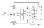
- FIG. 3is a block diagram of an IBR according to one embodiment of the invention.
- FIG. 4is a block diagram of an IBR antenna array according to one embodiment of the invention.
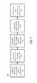
- FIG. 5shows a procedure for interference measurement of an established link according to one embodiment of the invention.
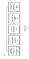
- FIG. 6shows a procedure to measure channel information across the band according to one embodiment of the invention.
- FIG. 7shows a procedure for a bi-directional transaction from an originator node to one or more responder nodes according to one embodiment of the invention.
- FIG. 8shows a procedure for an error recovery according to one embodiment of the invention.
- FIG. 9shows an additional procedure for an error recovery according to one embodiment of the invention.
- FIG. 10shows a procedure for an error that causes transaction failure according to one embodiment of the invention.
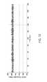
- FIG. 11shows a frequency domain sweep of the peak hold interference observed by an IBR in a 1 second period at a downtown San Jose, Calif. location in the 5.25-5.35 GHz band.
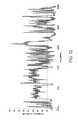
- FIG. 12shows a frequency domain sweep of the peak hold interference observed by an IBR in a 1 second period at a downtown San Jose, Calif. location in the 5.725-5.85 GHz band.
- FIG. 13shows the uplink throughput for an IBR link at a downtown San Jose, Calif. location in the 5.25-5.35 GHz band.
- FIG. 14shows the uplink throughput for an IBR link at a downtown San Jose, Calif. location in the 5.725-5.85 GHz band.
- FIG. 15Ashows a frequency domain sweep of the peak hold interference observed by an IBR in a first of three subsequent 5 ms periods at a downtown San Jose, Calif. location in the 5.725-5.85 GHz band.
- FIG. 15Bshows a frequency domain sweep of the peak hold interference observed by an IBR in a second of three subsequent 5 ms periods at a downtown San Jose, Calif. location in the 5.725-5.85 GHz band.
- FIG. 15Cshows a frequency domain sweep of the peak hold interference observed by an IBR in a third of three subsequent 5 ms periods at a downtown San Jose, Calif. location in the 5.725-5.85 GHz band.
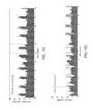
- FIG. 16Ashows a time domain sweep of the maximum instantaneous interference observed by an IBR at a first of three 20 MHz channels at a downtown San Jose, Calif. location in the 5.725-5.85 GHz band.
- FIG. 16Bshows a time domain sweep of the maximum instantaneous interference observed by an IBR at a second of three 20 MHz channels at a downtown San Jose, Calif. location in the 5.725-5.85 GHz band.
- FIG. 16Cshows a time domain sweep of the maximum instantaneous interference observed by an IBR at a third of three 20 MHz channels at a downtown San Jose, Calif. location in the 5.725-5.85 GHz band.
- FIG. 17Ashows a time domain sweep of the instantaneous interference observed at a first of eight receive antenna sub-arrays at a downtown San Jose, Calif. location in a 20 MHz channel at 5.805 GHz.
- FIG. 17Bshows a time domain sweep of the instantaneous interference observed at a second of eight receive antenna sub-arrays at a downtown San Jose, Calif. location in a 20 MHz channel at 5.805 GHz.
- FIG. 17Cshows a time domain sweep of the instantaneous interference observed at a third of eight receive antenna sub-arrays at a downtown San Jose, Calif. location in a 20 MHz channel at 5.805 GHz.
- FIG. 17Dshows a time domain sweep of the instantaneous interference observed at a fourth of eight receive antenna sub-arrays at a downtown San Jose, Calif. location in a 20 MHz channel at 5.805 GHz.
- FIG. 17Eshows a time domain sweep of the instantaneous interference observed at a fifth of eight receive antenna sub-arrays at a downtown San Jose, Calif. location in a 20 MHz channel at 5.805 GHz.
- FIG. 17Fshows a time domain sweep of the instantaneous interference observed at a sixth of eight receive antenna sub-arrays at a downtown San Jose, Calif. location in a 20 MHz channel at 5.805 GHz.
- FIG. 17Gshows a time domain sweep of the instantaneous interference observed at a seventh of eight receive antenna sub-arrays at a downtown San Jose, Calif. location in a 20 MHz channel at 5.805 GHz.
- FIG. 17Hshows a time domain sweep of the instantaneous interference observed at an eighth of eight receive antenna sub-arrays at a downtown San Jose, Calif. location in a 20 MHz channel at 5.805 GHz.
- FIG. 18Ashows a time domain sweep of the instantaneous interference observed at a fifth of eight receive antenna sub-arrays at a downtown San Jose, Calif. location in a 20 MHz channel at 5.805 GHz before application of a dominant interferer cancellation.
- FIG. 18Bshows a time domain sweep of the instantaneous interference observed at a fifth of eight receive antenna sub-arrays at a downtown San Jose, Calif. location in a 20 MHz channel at 5.805 GHz after application of a dominant interferer cancellation.
- FIG. 19is a block diagram of a transmit block processing section of an IBR according to one embodiment of the invention.
- FIG. 2illustrates deployment of intelligent backhaul radios (IBRs) in accordance with an embodiment of the invention.
- the IBRs 200are deployable at street level with obstructions such as trees 204 , hills 208 , buildings 212 , etc. between them.
- the IBRs 200are also deployable in configurations that include point to multipoint (PMP), as shown in FIG. 2 , as well as point to point (PTP).
- PMPpoint to multipoint
- PTPpoint to point
- each IBR 200may communicate with more than one other IBR 200 .
- cellular network infrastructureis more commonly deployed using “microcells” or “picocells.”
- compact base stations (eNodeBs) 216are situated outdoors at street level. When such eNodeBs 216 are unable to connect locally to optical fiber or a copper wireline of sufficient data bandwidth, then a wireless connection to a fiber “point of presence” (POP) requires obstructed LOS capabilities, as described herein.
- POPpoint of presence
- the IBRs 200include an Aggregation End IBR (AE-IBR) and Remote End IBRs (RE-IBRs).
- the eNodeB 216 associated with the AE-IBRis typically connected locally to the core network via a fiber POP 220 .
- the RE-IBRs and their associated eNodeBs 216are typically not connected to the core network via a wireline connection; instead, the RE-IBRs are wirelessly connected to the core network via the AE-IBR.
- the wireless connections between the IBRsinclude obstructions (i.e., there may be an obstructed LOS connection between the RE-IBRs and the AE-IBR).
- FIG. 3illustrates an exemplary embodiment of the IBRs 200 shown in FIG. 2 .
- the IBRs 200include interfaces 304 , interface bridge 308 , MAC 312 , modem 324 , channel MUX 328 , RF 332 , which includes Tx 1 . . . TxM 336 and Rx 1 . . . RxN 340 , antenna array 348 (includes multiple antennas 352 ), a Radio Link Controller (RLC) 356 and a Radio Resource Controller (RRC) 360 .
- the IBRmay optionally include an Intelligent Backhaul Management System (IBMS) agent as shown in FIG. 7 of U.S. patent application Ser. No. 14/337,744.
- IBMSIntelligent Backhaul Management System
- the external interfaces of the IBRare a starting point for describing some fundamental differences between the numerous different embodiments of the IBR 200 and either conventional PTP radios or other commonly known radio systems, such as those built to existing standards including 802.11n (WiFi), 802.11ac (WiFi), 802.16e (WiMax) or 4G LTE.
- the IBR Interface Bridge 308physically interfaces to standards-based wired data networking interfaces 304 as Ethernet 1 through Ethernet P. “P” represents a number of separate Ethernet interfaces over twisted-pair, coax or optical fiber.
- the IBR Interface Bridge 308can multiplex and buffer the P Ethernet interfaces 304 with the IBR MAC 312 .
- the IBR Interface Bridge 308preserves “Quality of Service” (QoS) or “Class of Service” (CoS) prioritization as indicated, for example, in IEEE 802.1q 3-bit Priority Code Point (PCP) fields within the Ethernet frame headers, such that either the IBR MAC 312 schedules such frames for transmission according to policies configured within or communicated to the IBR 200 , or the IBR interface bridge 308 schedules the transfer of such frames to the IBR MAC 312 such that the same net effect occurs.
- QoSQuality of Service
- CoSClass of Service
- the IBR interface bridge 308also forwards and prioritizes the delivery of frames to or from another IBR over an instant radio link based on Multiprotocol Label Switching (MPLS) or Multiprotocol Label Switching Transport Profile (MPLS-TP).
- MPLSMultiprotocol Label Switching
- MPLS-TPMultiprotocol Label Switching Transport Profile
- U.S. patent application Ser. No. 14/337,744provides additional description of exemplary embodiments of the interfaces 304 and the interface bridge 308 of the IBR 200 .
- U.S. patent application Ser. No. 13/632,993provides additional description of exemplary embodiments of an IBMS that includes an IBMS Agent in communication with or IBMS components and the IBR Interface Bridge 308 as well as MAC 312 and/or RRC 360 .
- U.S. patent application Ser. No. 13/632,993also describes an IBR with an integrated Carrier Ethernet switch.
- FIG. 4illustrates an exemplary embodiment of an IBR Antenna Array 348 .
- FIG. 4illustrates an antenna array having Q directive gain antennas 352 (i.e., where the number of antennas is greater than 1).
- the IBR Antenna Array 348includes an IBR RF Switch Fabric 412 , RF interconnections 404 , a set of Front-ends 408 and the directive gain antennas 352 .
- the RF interconnections 404can be, for example, circuit board traces and/or coaxial cables.
- the RF interconnections 404connect the IBR RF Switch Fabric 412 and the set of Front-ends 408 .
- Each Front-end 408is associated with an individual directive gain antenna 352 , numbered consecutively from 1 to Q.
- Front-end 408may include a transmit/receive switch, one or more RF low pass and/or bandpass filters, and either a low-noise amplifier (LNA) in the receive path or a power amplifier (PA) in the transmit path.
- LNAlow-noise amplifier
- PApower amplifier
- Front-end 408may include a duplex filter, one or more additional RF low pass and/or bandpass filters, and either a low-noise amplifier (LNA) in the receive path or a power amplifier (PA) in the transmit path.
- LNAlow-noise amplifier
- PApower amplifier
- Another common embodiment for FDDhas certain directive gain antenna elements 352 used only for transmit and then Front-end 408 for such transmit antenna elements would have a PA and one or more RF filters for a transmit FDD sub-band and has certain directive gain antenna elements 352 used only for receive and then Front-end 408 for such receive antenna elements would have an LNA and one or more RF filters for a receive FDD sub-band.
- certain directive gain antenna elements 352are used only for transmit and others only for receive with respective Front-ends as described for FDD except that the RF filters overlap in the frequency domain for both transmit and receive (i.e. no separate transmit and receive sub-bands).
- each antenna 352has a directivity gain Gq.
- each directive gain antenna 352may use only moderate directivity compared to antennas in conventional PTP systems at a comparable RF transmission frequency.
- typical values of Gqare on the order of 10 to 20 dBi for each antenna at RF transmission frequencies below 10 GHz.
- the total number of individual antenna elements 352 , Qis at least greater than or equal to the larger of the number of RF transmit chains 336 , M, and the number of RF receive chains 340 , N.
- some or all of the antennas 352may be split into pairs of polarization diverse antenna elements realized by either two separate feeds to a nominally single radiating element or by a pair of separate orthogonally oriented radiating elements.
- certain antenna elements 352may be configured with different antenna gain Gq and/or radiation patterns compared to others in the same IBR.
- U.S. patent application Ser. Nos. 14/337,744, 14/336,958, 14/197,158, and 14/108,200provide additional description of advantageous arrangements of separate transmit and receive antenna subsets with the total set Q of individual antenna elements 352 .
- the IBR RF Switch Fabric 412provides selectable RF connections between certain RF-Tx-m and/or certain RF-Rx-n to the various individual antenna elements 352 via various front-end 408 embodiments.
- the RF Switch Fabric 412is comprised of one or more RF switches where each RF switch has a selective set of one or mappings between the two or more RF ports on each switch.
- the individual antenna elements 352are coupled via a transmit-only front-end and/or the IBR RF Switch Fabric 412 to only a transmit chain output RF-Tx-m or coupled via a receive-only front-end and/or the IBR RF Switch Fabric 412 to only a receive chain output RF-Rx-n to advantageously enable separate optimization of the receive antenna array from that of the transmit antenna array.
- U.S. patent application Ser. Nos. 14/337,744, 14/336,958, and 14/108,200provide additional description of different embodiments of the IBR RF Switch Fabric 412 as applicable to TDD, FDD and ZDD in different product configurations.
- IBR embodimentsmay provide selectable RF connections between certain RF-Tx-m and/or certain RF-Rx-n to the various individual antenna elements 352 via various front-end 408 embodiments with structures different than the IBR RF Switch Fabric 412 , as also disclosed at least in U.S. patent application Ser. No. 14/337,744.
- certain IBR embodimentsmay utilize selective coupling structures between antenna elements and RF chains that comprise combiners or splitters where the phase and/or amplitude of a transmit or receive signal in certain paths of a combiner or splitter can be different from that of other paths.
- such selective coupling structuresmay include one or more upconverters or downconverters such that at least one splitter or combiner may include at least one path at an intermediate frequency (IF).
- IFintermediate frequency
- one or more switches in the implementation of the selectable RF connectionsmay also operate at IF.
- the actual instant selective coupling parameterssuch as a switch setting, or a path phase and/or an amplitude, or a splitting or combining path selection may be characterized by an appropriate set of selective coupling settings.
- the Radio Resource Control (RRC) 360may generate or cause to be generated such a set of selective coupling settings.
- the IBR RF 332also includes transmit RF and receive RF chains 336 , 340 .
- each element of transmit RF chain 336takes a transmit chain input signal such as digital baseband quadrature signals I Tm and Q Tm and then converts them to a transmit RF signal RF-Tx-m at an RF carrier frequency typically below 10 GHz.
- each element of receive RF chain 340converts a receive RF signal RF-Rx-n at an RF carrier frequency typically below 10 GHz to a receive chain output signal such as digital baseband quadrature signals I Rn and Q Rn .
- each receive RF chaincomprises at least a vector demodulator and two analog to digital converters that are capable of producing such digital baseband quadrature signals I Rn and Q Rn .
- each transmit RF chaincomprises at least a vector modulator and two digital to analog converters that are capable of operating from such digital baseband quadrature signals I Tm and Q Tm .
- the transmit RF and/or receive RF chainsmay operate at or operate with an intermediate frequency (or IF) that is also respectively upconverted or downconverted to the instant RF carrier frequency.
- Such upconverters or downconvertersmay be comprised within such transmit RF or receive RF chains. In some embodiments, such upconverters or downconverters may be comprised within the selectable RF connections as described above.
- IBR elementsinclude the IBR MAC 312 , the Radio Link Control (RLC) 356 , the Radio Resource Control (RRC) 360 and the optional IBMS Agent.
- RLCRadio Link Control
- RRCRadio Resource Control
- IBR embodimentsare possible wherein the MAC 312 , RLC 356 , RRC 360 and the optional IBMS Agent are distinct structural entities, more commonly IBRs are realized wherein the MAC 312 , RLC 356 , RRC 360 and the optional IBMS Agent as well as portions of the IBR Interface Bridge 308 are software modules executing on one or more microprocessors.
- SDRSoftware Defined Radio
- the one or more microprocessors used for elements of the PHY layerare physically separate from those used for the MAC 312 or other layers and are physically connected or connectable to certain hardware cores such as FFTs, Viterbi decoders, DFEs, etc.
- the RRC 360 and RLC 356may interact with the IBR MAC 312 and various elements of the IBR PHY at either the instant IBR or other IBRs in the instant link via “normal” frame transfers, direct local control signals via the conceptual IBR Control plane, or certain fields within a link control block that is transmitted periodically in certain superframes. Both the RRC 360 and the RLC 356 may execute concurrent control loops with the respective goals of optimizing radio resource allocations and optimizing radio link parameters for current resources in view of the dynamic propagation environment conditions (including uncoordinated interference if applicable), IBR loading, and possibly system-wide performance goals (via the optional IBMS Agent or other IBR to IBR control communications links).
- both the RRC 360 and the RLC 356are implemented as software modules executing on one or more processors.
- the primary responsibility of the RLC 356 in exemplary IBRsis to set or cause to be set the current transmit Modulation and Coding Scheme (MCS) and output power for each active link.
- the RLC 356causes the transmit power control (TPC) of the IBR to be maintained both in a relative sense amongst active links, particularly of interest for the AE-IBR in a PMP configuration, and also in an overall sense across all transmits chains and antennas.
- the RRCperforms some or all of the transmit power control (TPC) functionality.
- the RLC 356can determine its MCS and TPC selections across active links based on information from various sources within the IBR.
- the IBR MACcan deliver RLC control frames from other IBRs with information from such other IBRs (for example, RSSI, decoder metrics, FCS failure rates, etc.) that is useful in setting MCS and TPC at the transmitting IBR.
- RLC control frames from an associated IBRmay directly request or demand that the RLC in the instant IBR change its MCS and/or TPC values for transmit directly on either a relative or absolute basis.
- 14/337,744 and 14/108,200provide additional description of different embodiments of the RLC 356 as applicable to TDD, FDD and ZDD in different product configurations.
- the link control blockmay be used in place of or in addition to such control frames to carry such information.
- the primary responsibility of the RRC 360is to set or cause to be set at least the one or more active RF carrier frequencies (or alternatively, active RF channel center frequencies), the one or more active channel bandwidths, the choice of transmit and receive channel equalization and multiplexing strategies, the configuration and assignment of one or more modulated streams amongst one of more modulator cores, the number of active transmit and receive RF chains, and the selection of certain antenna elements and their mappings to the various RF chains (the set of selective coupling settings).
- the RRCmay also set or cause to be set the superframe timing, the cyclic prefix length, and/or the criteria by which blocks of Training Pilots are inserted.
- the RRC 360allocates portions of the IBR operational resources, including time multiplexing of currently selected resources, to the task of testing certain links between an AE-IBR and one or more RE-IBRs.
- the RRC 360evaluates such tests by monitoring at least the same link quality metrics as used by the RLC 656 . Additionally, in some embodiments, additional RRC-specific link testing metrics are also used.
- the RRC 360can also exchange control frames or control signaling using the link control block with a peer RRC at the other end of an instant link to, for example, provide certain link testing metrics or request or direct the peer RRC to obtain link specific testing metrics at the other end of the instant link for communication back to RRC 360 .
- the RRC 360causes changes to current resource assignments in response to tested alternatives based on policies that are configured in the IBR and/or set by the optional IBMS Agent.
- An exemplary policyincludes selecting resources based on link quality metrics predicted to allow the highest throughput MCS settings at lowest TPC value. Additional exemplary policies may factor in minimizing interference by the instant link to other AE-IBR to RE-IBR links (or other radio channel users such as conventional PTP radios) either detected at the instant IBRs or known to exist at certain physical locations nearby as set in configuration tables or communicated by the optional IBMS Agent or other IBR to IBR control communications links as described, for example, in co-pending U.S. patent application Ser. No. 14/098,456, the entirety of which is hereby incorporated by reference.
- U.S. Patent Application Serial No. 14/098,456discloses exemplary systems and methods for control communications links in the form of inline or embedded signals that may be suitable for exchange of control information between IBRs that otherwise lack any IBR to IBR communication path. Such policies may also be weighted proportionately to reach a blended optimum choice amongst policy goals or ranked sequentially in importance.
- the selection of either the one or more active RF carrier frequencies used by the RF chains of the IBR RF, the one or more active channel bandwidths used by the IBR MAC, IBR Modem, IBR Channel MUX and IBR RF, the superframe timing, the cyclic prefix length, or the insertion policy for blocks of Training Pilotsis determined at the AE-IBR for any given link.
- the RE-IBR in such an arrangementcan request, for example, an RF carrier frequency or channel bandwidth change by the AE-IBR by sending an RRC control frame in response to current link conditions at the RE-IBR and its current RRC policies.
- an AE-IBRsends the affected RE-IBRs an RRC control frame specifying at least the parameters for the new RF frequency and/or channel bandwidth of the affected links as well as a proposed time, such as a certain superframe sequence index, at which the change-over will occur (or alternatively, denies the request).
- the AE-IBRthen makes the specified change after receiving confirmation RRC control frames from the affected RE-IBRs or sends a cancellation RRC control frame if such confirmations are not received before the scheduled change.
- RRCmay send such information on the link control block instead of or in addition to using control frames.
- An RE-IBRtypically attempts to utilize all available modulator and demodulator cores and streams as well as all available RF chains to maximize the robustness of its link to a particular AE-IBR.
- the primary local RRC decisionis then to set these various antenna selectivity options.
- the AE-IBR and RE-IBRoptimize their resource allocations independently such that there is little distinction between the RRC strategies at the AE-IBR versus the RE-IBR.
- U.S. patent application Ser. Nos. 14/337,744, 14/336,958, and 14/108,200provide additional description of different embodiments of the RRC 360 as applicable to TDD, FDD and ZDD in different product configurations.
- IBR Modem 324 and IBR Channel MUX 328depend somewhat on the specific modulation format(s) deployed by the IBR.
- the IBRrequires a modulation format suitable for a broadband channel subject to frequency-selective fading and multipath self-interference due to the desired PHY data rates and ranges in obstructed LOS propagation environments.
- Many known modulation formats for such broadband channelsare possible for the IBR.
- Two such modulation formats for the IBRare (1) Orthogonal Frequency Division Multiplexing (OFDM) and (2) Single-Carrier Frequency Domain Equalization (SC-FDE). Both modulation formats are well known, share common implementation elements, and have various advantages and disadvantages relative to each other.
- OFDMOrthogonal Frequency Division Multiplexing
- SC-FDESingle-Carrier Frequency Domain Equalization
- the IBRutilizes multiple antennas and transmit and/or receive chains, which can be utilized advantageously by several well-known baseband signal processing techniques that exploit multipath broadband channel propagation.
- Such techniquesinclude Multiple-Input, Multiple-Output (MIMO), MIMO Spatial Multiplexing (MIMO-SM), beamforming (BF), maximal ratio combining (MRC), and Space Division Multiple Access (SDMA).
- MIMOMultiple-Input, Multiple-Output
- MIMO-SMMIMO Spatial Multiplexing
- BFbeamforming
- MRCmaximal ratio combining
- SDMASpace Division Multiple Access
- the IBR Modem 324comprises one or modulator cores each of which comprises such functional elements as scramblers, encoders, interleavers, stream parsers, symbol groupers and symbol mappers.
- each modulator core within the IBR Modem 324typically transforms a data stream from the IBR MAC 312 into a symbol stream that can be passed to the IBR Channel MUX 328 .
- the IBR Modem 324also comprises one or demodulator cores each of which comprises such functional elements as descramblers, decoders, deinterleavers, stream multiplexers, and soft decision symbol demappers.
- each demodulator core within the IBR Modem 324typically transforms a stream of estimated receive symbols, such as represented by a Log-Likelihood Ratio (LLR), from the IBR Channel MUX 328 into a data stream that can be passed to the IBR MAC 312 .
- LLRLog-Likelihood Ratio
- U.S. patent application Ser. Nos. 14/337,744, 14/336,958, and 14/108,200provide additional description of different embodiments of the IBR Modem 324 as applicable to TDD, FDD and ZDD in different product configurations.
- the IBR Channel MUX 328comprises a transmit path channel multiplexer that may or may not be frequency selective and that in turn may comprise such functional elements as block assemblers, transmit channel equalizers, transmit multiplexers, cyclic prefix adders, block serializers, transmit digital front ends, preamble inserters, and pilot inserters.
- the transmit path of the IBR Channel MUX 328transforms one or more symbol streams from the IBR Modem 324 into inputs for the one or more transmit chains each comprised of baseband symbol samples.
- the IBR Channel MUX 328also comprises a frequency selective receive path channel multiplexer that in turn may comprise such functional elements as synchronizers, receive digital front ends, cyclic prefix removers, channel equalizer coefficients generators, receive channel equalizers, receive stream multiplexers and complex Discrete Fourier Transformers (DFT).
- a frequency selective receive path channel multiplexerthat in turn may comprise such functional elements as synchronizers, receive digital front ends, cyclic prefix removers, channel equalizer coefficients generators, receive channel equalizers, receive stream multiplexers and complex Discrete Fourier Transformers (DFT).
- DFTDiscrete Fourier Transformers
- Such exemplary frequency selective receive path channel multiplexersmay also comprise at least one of a Space Division Multiple Access (SDMA) combiner or equalizer, a maximal ratio combining (MRC) combiner or equalizer, a minimum mean squared error (MNISE) combiner or equalizer, an Eigen Beam Forming (EBF) combiner or equalizer, a receive beam forming (BF) combiner or equalizer, a Zero Forcing (ZF) combiner or equalizer, a channel estimator, a Maximal Likelihood (DL) detector, an Interference Canceller (IC), a VBLAST combiner or equalizer, a Discrete Fourier Transformer (DFT), a Fast Fourier Transformer (FFT), or an Inverse Fast Fourier Transformer (IFFT).
- SDMASpace Division Multiple Access
- MRCmaximal ratio combining
- MNISEminimum mean squared error
- EBFEigen Beam Forming
- ZFZero Forcing
- a channel estimatora Maximal Likelihood (DL) detector
- ICInter
- the receive path of the IBR Channel MUX 328transforms the outputs of the one or more receive chains each comprised of baseband symbol samples into one or more streams of estimated receive symbols for input into the IBR Modem 324 .
- U.S. patent application Ser. Nos. 14/337,744, 14/336,958, and 14/108,200provide additional description of different embodiments of the IBR Channel MUX 328 as applicable to TDD, FDD and ZDD in different product configurations.
- the IBR MAC 312comprises such functional elements as a management entity, a Tx buffer and scheduler, a control entity, an Rx buffer, a frame check sum (FCS) generator, a header generator, a header analyzer and an FCS analyzer.
- FCSframe check sum
- U.S. patent application Ser. Nos. 14/337,744, 14/336,958, and 14/108,200provide additional description of different embodiments of the IBR MAC 312 as applicable to TDD, FDD and ZDD in different product configurations.
- the IBR at startup and during normal operationmay scan at the receiver of each link for the minimally interfered frequency spectrum within the available receiver band of operation.
- the IBRmay optimize its channel bandwidth and channel center frequency to correspond to minimally interfered frequency spectrum.
- multiple channels within the available receiver band of operationmay be selected simultaneously based on non-contiguous channel aggregation.
- the IBR performing this optimization at its receivermay communicate this optimal frequency channel characteristics to the transmitting IBR in its instant link so that the transmitting IBR adopts these optimal frequency channel characteristics in subsequent transmissions.
- the IBRmay communicate to the transmitting IBR in its instant link at the minimum supported channel bandwidth to increase the probability that the transmitting IBR in its instant link successfully receives the communication with this optimal frequency channel characteristics information. In this way, the IBR mitigates interference in the frequency domain.
- the receivers at both ends of an instant IBR linkmay perform these receiver channel scans and other interference mitigation techniques described herein independently to advantageously optimize the use of minimally interfered frequency spectrum or other receiver resources at each end of the link separately since each end in a backhaul application is typically far enough apart that the interference environment is different at each receiver.
- the IBRalso mitigates intermittent interference in the combined frequency and time domains by changing one or both of the channel center frequency and channel bandwidth (possibly for multiple aggregated channels individually) as a function of time as interference conditions change in the time domain.
- the timescale at which these changes occurcan be, for example, several superframes, on a superframe by superframe basis, on a block by block basis, or within a block as may be practical given the hardware limitations of a particular IBR implementation.
- an IBRmay signal the desired change either via a MAC Control frame sent in the previous superframe or by certain control flags set within a given transmit block or symbol block such as a link control block.
- the time to effect the change in channel bandwidth and/or center frequencymay occur in one or more blank or non-payload transmit blocks at the end of a superframe so that blocks are not sent or received in error while the IBR Channel MUX or the transmit and/or receive RF chains are transitioning their channel bandwidth or center frequency.
- the superframeis typically on the order of 200 to 2000 ⁇ s duration and composed of transmit blocks of typically 10 to 30 ⁇ s duration.
- each IBR superframecomprises multiple transmit blocks including at least one preamble block that may be used at least for synchronization and/or channel estimation (or for channel propagation characteristics assessment), at least one link control block that provides information such as the Modulation and Coding Scheme (or “MCS”) for the data blocks in the instant or subsequent superframe, and at least several data blocks that can comprise control, management and/or user information bits.
- MCSModulation and Coding Scheme
- IBRsmay advantageously optimize the superframe duration at either or both of startup or dynamically during operation to increase superframe duration at times of minimal interference when infrequent frequency agility in channel bandwidth and/or center frequency is required; thereby, minimizing the non-payload overhead associated with short duration superframes.
- IBRsmay advantageously optimize the superframe duration at either or both of startup or dynamically during operation to decrease superframe duration at times of significant interference that require continuous frequency agility in channel bandwidth and/or center frequency; thereby, minimizing the time required to make a channel bandwidth and channel center frequency change to correspond to minimally interfered frequency spectrum.
- IBRsmay change channel center frequency and channel bandwidth on a block by block basis by signaling such changes in an FDD or ZDD scheme with control flags appended to a transmit block to minimize processing latency in receiving such control flags and making the signaled change.
- IBRsmay use an immediate preamble block transmission to enable determination of updated channel estimation or may derive a temporary estimation for use until the next regularly scheduled preamble by interpolating, extrapolating and/or recalling from previously stored channel estimation.
- interference mitigation in the time domainis also enhanced by block level retransmission.
- Thisenables otherwise unmitigated interference that causes block errors at the receiver to be corrected at minimal latency to the affected data frame(s).
- an ACK or NACKis sent as a control flag with a block identifier to minimize latency in causing a transmitter to re-transmit a buffered block.
- control flags and identifiersare appended to transmit blocks after all bit processing operations to minimize the block processing latency associated with such function as encoding, interleaving, scrambling, encrypting, etc. and their inverse operations at the receiver.
- IBRsadvantageously use a multitude of diverse receive antennas.
- the number of receive RF chains, each of which can be coupled to at least one distinct receive antennaequals or exceeds the number of receive symbol streams and the number of distinct receive antennas that collectively provide diversity in the spatial domain exceeds the number of receive symbol streams.
- the spatial domain diversitymay be achieved by distinct receive antennas that are i) separated physically in space, by at least one half wavelength but preferably by multiple wavelengths, ii) separated in directional orientation, in either azimuth or elevation but preferably at least such that their respective azimuthal beam widths do not substantially overlap, or iii) separated in polarization such as vertical and horizontal or other known orthogonal polarizations.
- Many embodiments of the IBRuse a combination of at least two of the above spatial domain diversity alternatives and some embodiments of the IBR use a combination of spatial domain diversity based upon all three—physical separation, azimuthal orientation, and orthogonal polarization.
- Exemplary antenna arraysthat embody the combination of spatial domain diversity based upon physical separation, azimuthal orientation, and orthogonal polarization are shown in FIGS. 52A, 52B, 52C, 53A, 53B, 53C and 53D of co-pending U.S. patent application Ser. No. 14/336,958 and U.S. Pat. Nos. 8,824,442 and 8,467,363 and incorporated herein by reference for sub-arrays of patch antenna elements using pin feeds.
- sub-arrays of patch antenna elements or stacked patch antenna elements using aperture feeds for such antenna arraysare shown in FIGS. 5A, 5B, 5C, 6, 7, 8A, 8B, 8C, 8D, 8E, 8F and 9 of co-pending U.S. patent application Ser. No. 14/197,158 and incorporated herein by reference.
- IBRsalso preferably scan during startup and normal operation the available spatially diverse receive antennas at the current frequency channel center frequency and bandwidth.
- the number of spatially diverse receive antennas based upon physical separation, azimuthal orientation, or orthogonal polarization, or combinations thereof,exceeds the number of receive symbol streams and preferably also the number of receive RF chains.
- IBRsuse the results of scanning such spatially diverse receive antennas to determine the amount of interference and/or the instant signal to noise plus interference for each such receive antenna.
- IBRsadvantageously selectively couple certain of such spatially diverse receive antennas or optimally combined subsets thereof to the available receive RF chains to mitigate the effects of uncoordinated interference on the instant, average or worst case performance of the receiver.
- the number of available spatially diverse receive antennas or optimally combined subsets thereofexceeds the number of receive RF chains and thus the IBRs selectively couple the best performing subset using, for example only, a switch matrix or a phase/amplitude combiner network driven on a time adaptive basis, typically from a radio resource controller (RRC), to change the effect of the selective couplings over time as the optimal spatial combination changes.
- RRCradio resource controller
- IBRsalso preferably scan during startup and normal operation the available spatially diverse receive antennas at other frequency channel centers and bandwidths available within the allocated receiver band of operation. This enables preferred embodiments of the IBR to simultaneously select optimal channel center frequency and bandwidth and selectively couple the best performing subset of receive antennas as a function of both frequency and space on a time adaptive basis, typically from the RRC, to change both instant frequency center and bandwidth and the antenna selective couplings over time as the optimal spatial and frequency parameter combinations change. This is an example of optimization of the IBR performance in view of uncoordinated interference in the combined frequency, time and spatial domains.
- IBRsadvantageously also employ interference cancellation signal processing as part of the receive path in the IBR Channel MUX.
- the number of receive RF chainsexceeds the number of receive symbol streams and the additional diversity afforded by this excess of receiver resources can be utilized to advantageously cancel at least one significant interference source via certain signal processing techniques.
- the selective coupling of receive antennas to receive RF chains and/or the selection of frequency channel center and bandwidth, typically by the RRC,is predicated on desired IBR performance metrics after application of interference cancellation instead of before.
- such IBRsmay opt for a combination of certain selectively coupled receive antennas plus frequency channel centers or bandwidths that are impaired by a relatively large interferer amenable to significant interference cancellation rather than opt for a different combination with relatively less interference power but wherein such interference originates from sources not amenable to significant interference cancellation.
- Thisis an example of optimization of the IBR performance in view of uncoordinated interference in the combined frequency, time, cancellation and spatial domains.
- certain IBR embodimentsmay also adapt the usage of combinations of selectively coupled receive antennas plus frequency channel centers or bandwidths that comprise a relatively large interferer amenable to significant interference cancellation rather than combinations with relatively small interferers not amenable to significant interference cancellation as a function of changing conditions over time. This is an example of optimization of the IBR performance in view of uncoordinated interference in the combined frequency, time, cancellation and spatial domains.
- IBRsuse certain adjunct receive antennas, also known as “probe-in-space” or “sniffer” antennas, with significantly different channel response characteristics such as directivity, orientation and/or polarization than those usually expected to provide strong reception of the desired IBR RF transmission such that such adjunct antennas may experience interference signal power at a greater ratio to that of the desired IBR RF transmission.
- adjunct receive antennasalso known as “probe-in-space” or “sniffer” antennas
- such IBRsmay optimally select such adjunct antennas to be selectively coupled to at least one receive RF chain such that the IBR Channel MUX, or other IBR receiver element, can exploit a relatively strong reception at such adjunct antenna of an interferer otherwise only nominally detectable in a desired receive signal path, but yet significant enough to limit performance below that possible without such interference, such that an interference cancellation results within such receive RF chain signal processing path and tracks such interference accurately over time on a sample by sample basis.
- an interference cancellationis never a “complete” cancellation.
- the performance gains from an at least partial cancellation as described hereincan be substantial for certain arrangements of the interference source relative to the desired transmitter source.
- adjunct antennasmay be physically located as separated from the desired signal transmit and/or receive antenna array elements.
- an adjunct antennamay be physically located at the bottom or top of a horizontally or vertically arranged antenna array or alternatively may be located in between transmit antenna elements and receive antenna elements in a vertically arranged antenna array.
- such adjunct antennasmay be nominally omnidirectional at least in the azimuthal orientation.
- adjunct antennasmay be nominally of opposite directionality to the collective azimuthal coverage pattern in the azimuthal orientation and/or of broader elevation coverage pattern to increase the relative difference in desired signal to undesired interference ratio between the adjunct antenna(s) and the desired receive antenna array elements at least for interference sources that are not co-directional with the desired receive signal orientation.
- multiple such adjunct antennasmay each be co-polarized with a subset of the desired receive antenna array elements or may be cross-polarized with respect to two polarizations within the desired receive antenna array elements.
- a receive antenna signal processing pathhad an interference level from a particular source that was 10 dB lower than the desired signal level but such interference level was also 10 dB higher than the effective noise floor, then performance would be significantly limited by such particular source interferer.
- an adjunct antennahad different characteristics of directivity, orientation and/or polarization relative to the desired signal source versus the particular interference source by, for example, 20 dB, then in the adjunct path the interference level may be 10 dB higher than the desired signal. This asymmetry in signal to interference ratio between such paths enables a simple transfer function between such paths, in either the frequency or time domains, to be determined.
- a substantial interference cancellation of approximately 10 dBwould be achieved at the example levels described above.
- a particular advantage of performing interference cancellation in this manneris that such cancellation can be adaptively trained over time such that the cancellation operation works even with rapidly time-varying intensity levels for the interference source to the extent that the relative transfer function between the adjunct and desired paths is largely time invariant as would be expected with fixed devices.
- adjunct antenna element(s)for such interference cancellation with the other interference mitigation techniques described herein is thus another example of optimization of the IBR performance in view of uncoordinated interference in the combined frequency, time, cancellation and spatial domains.
- adjunct antenna(s)may also be used simultaneously to detect radars in conformance with Dynamic Frequency Selection (DFS) government regulations requiring avoidance of interference by the IBR with the operation of such radars, such as disclosed for FDD or ZDD backhaul radios in co-pending U.S. patent application Ser. No. 14/151,190.
- such adjunct antennasmay be used to detect and demodulate known interferers such as 802.11a, 802.11n, or 802.11ac (or “WiFi”) and then apply additional signal cancellation of such interferers from the desired signals in the spatially diverse receive signal processing paths.
- certain adaptation of the instantaneous selective antenna couplings from transmit RF chains to directive gain transmit antenna elementsmay preferably have improved link performance relative to interference from other IBRs or uncoordinated sources if upon testing such a candidate change at the receiving IBR, such receiving IBR also sends an indication of such change to the transmitting IBR so that such transmitting IBR can adjust its transmit antenna pattern or IBR Channel MUX transmit path equalization parameters.
- Uncoordinated interference in frequency bands of interest to IBR operationis observed as appearing and leaving on short time scales of order 100 ⁇ s, for example.
- FDD and ZDD backhaul radio systemshave inherent advantages over TDD systems in terms of minimizing such interference driven signaling latency because such FDD or ZDD systems are normally transmitting and receiving at the same time.
- interference indication signaling techniquessuch as control frames or appended control bits to each transmit block do not have to wait until the transmit portion of a superframe arrives as in TDD in order to be signaled to the other IBR in the instant link.
- such control indicators associated with interference detection signalingare also communicated so as to avoid the multiple block processing delays for encoding, interleaving, scrambling, encrypting, etc. in the transmit path and their inverse operations in the receive path.
- Exemplary techniques that avoid such block processing delaysinclude appending bits or symbol samples to otherwise completed blocks, adding specific tones in the frequency domain that carry such signaling modulation, or combining sub-signals such as orthogonal direct sequence spread spectrum (DSSS) with the normal transmit block symbols.
- DSSSorthogonal direct sequence spread spectrum
- One technique that certain IBR embodiments may use to enhance the robustness of such interference driven indication signalingis to use a modulation/coding scheme specifically for the indication signaling information that is more robust than that of the instant link in the feedback path and/or has more coding than that of the instant link in the feedback path.
- codingmay incur additional latency in the decoder and thus low latency decoding techniques such as Reed Muller codes may be preferable.
- to achieve robustness in these waysmay require considerable overhead that detracts from the payload performance throughput in the feedback path and creates another consideration for the design of such a signaling system.
- IBRscould accumulate mutually shared lists of alternative operating parameters sets of, for example, channel center frequency, channel bandwidth and/or transmit antenna pattern combinations so that the signaling need only point to the index of one of these sets. For example, if four current sets are maintained, this may be signaled with only 2 bits. These sets may be established and updated over time via normal IBR control or management frames communicated between peer RRC or MAC entities. Alternatively, the signaling could be as little as 1 bit if setting such bit indicated only an advance of the index to the next set of parameters in the shared lists.
- interference detection signalingwith reserved control bits in each normal transmit block
- these reserved control bitsare set appropriately before forward error correction encoding for the symbol block.
- the forward error correction output corresponding to desired values of the reserved control bitsare combined from a “look up table” (or “LUT”) with the rest of the encoded symbol block as part of the processing to form each normal transmit block.
- Such embodimentsneed additional implementation complexity but advantageously reduce the latency between determining interference detection at a receiver of an instant IBR link and communicating such interference detection to one or more transmitters of an instant IBR link such that resource allocation changes can be made.
- IBRsmay use to signal interference driven indications for operating parameter changes with zero overhead in normal conditions where changes are not needed is to signal the interference driven change with interference signaling blocks substituted for the normal transmit block at the soonest available transmit block opportunity. For example, when a receiving IBR detects interference that triggers a need to change operating parameters at both receiving and transmitting IBRs for that instant link, then at the next available transmit block opportunity in the feedback path link, such a receiving IBR may transmit a predetermined block of transmit samples that comprise the indicated change that would be detected in the receiver of the transmitting IBR for the interference-affected link.
- An exemplary interference signaling blockis a sequence of time domain samples that are multiplexed into the transmit RF chains when interference signaling is triggered at the receiving IBR that detects the presence or absence of interference on its instant link.
- Such an interference signaling blockis composed of a signature that when passed through a matched filter in either the time domain or frequency domain in the receive path can be used to detect the signaled bit(s) that indicate the operating parameter changes or the list index.
- interference signaling signaturesare chosen to minimally correlate to the matched filtering of normal payload transmit blocks to avoid false triggering of operating parameter changes at the transmitting IBR.
- the interference signaling block techniquehas very low overhead when interference indications are rare but its overhead of an entire transmit block may be larger than other techniques described herein when interference signaling is frequent.
- the signaling methodologyis also adaptive to use the technique that minimizes overhead depending on the time varying nature of the observed interference patterns.
- IBRspreferably also include a recovery capability to minimize the time in which the transmitter and receiver operate with incompatible or sub-optimal operating parameters due to such errors. For example, IBRs may always maintain a mutually agreed upon recovery set of parameters to be used when a predetermined number of incorrectly received blocks are encountered.
- IBRspreferably change operating parameters even when the combination of frequency, time, spatial, and/or cancellation domain adaptation leads to acceptable link performance so that the instant IBR link reduces interference caused to other spectrum users in the vicinity.
- the other usersare IBRs that may be detected via the IBMS and/or other methodology such as a self-organizing in-band signal as described in co-pending U.S. patent application Ser. No. 14/098,456.
- a WiFi AP with a BSSID or SSID on a protected listis detected and the IBR link adjusts operating parameters to minimize interference to such protected WiFi networks.
- both channel conditions and interference in the environmentneeds to be assessed periodically. This assessment needs to be performed accurately and continuously for optimum selection of resources across the combined frequency, time, cancellation and spatial domains but also with minimal usage of the radio resources essential to providing high throughput and low latency link performance at all times.
- channel and interference assessment on the IBRis carried out across all frequencies and receive antennas available for operation.
- receive antennasmay include directive gain antenna elements such as the receive antenna sub-arrays described in co-pending U.S. patent application Ser. No. 14/336,958 and U.S. Pat. Nos. 8,824,442 and 8,467,363 or in co-pending U.S. patent application Ser. No. 14/197,158, or may include one or more adjunct antennas as described herein.
- the received signalis analyzed in the frequency domain for some embodiments. For example, interference energy may be accumulated in frequency bins of a fixed size.
- the corresponding valueis then stored for each receive antenna or for each set of selective coupling settings as appropriate at the particular channel frequency/bandwidth. Interference varies over time across space and frequency, so a large sample size is taken and statistical measures are used to improve reliability and utility of the estimate.
- Channel estimatesthat may provide a measure of a channel propagation characteristics assessment for a given combination of channel center frequency, channel bandwidth and set of selective coupling settings are taken using known preamble sequences at the transmitter and receiver to extract channel information using techniques known in the art.
- the frequency selective receive path channel multiplexeris used to measure the interference present in one or more of the receive chain output signals that are input to the frequency selective receive path channel multiplexer.
- the frequency selective receive path channel multiplexermay measure such interference energy in frequency bins using a Discrete Fourier Transform or a Fast Fourier Transform. Also, the frequency selective receive path channel multiplexer may be used to provide the channel estimates for a given combination of channel center frequency, channel bandwidth and set of selective coupling settings.
- Interference measurementcan be done before and after the link is established. To perform this operation before the link is established, it is sufficient to use the transceivers to sweep all receive antenna and channel frequency/bandwidth combinations without self-interference.
- IBR embodimentsuse a communication protocol to create a blanking interval wherein the one or more transmitters in communication with the instant IBR blanks (zeros) its signal for some pre-arranged periods of time, and the receiver of the instant IBR then performs measurements during the blanked out portions to measure the interference and noise level in the environment at its various receive antenna selective coupling and channel frequency/bandwidth combinations.
- zerosinstant IBR blanks
- FIG. 5shows a procedure 500 for interference measurement of an established link according to one embodiment of the invention.
- the procedure 500begins with the receiver using an alternate subset of the available receive RF chains and selectively coupling resources to measure interference in a candidate channel defined by a channel frequency/bandwidth and receive antenna combination that is different from that of a current channel used by the instant link (block 501 ).
- the receiverobtains a measurement of the received signal energy and stores the result (block 503 ).
- the alternate subset of the available receive RF chains and selectively coupling resourcesis set to a different candidate channel defined by a channel frequency/bandwidth and receive antenna combination (block 504 ).
- the steps in blocks 501 - 504may then be repeated for a multiplicity of channel frequency/bandwidth and receive antenna combinations (block 505 ).
- the receiverIn order to blank out portions of the superframes at the transmitter, the receiver maintains the link while doing measurements so performance of the link is not impacted significantly.
- an alternate subset of the available receive RF chains and selectively coupling resourcesis utilized for these measurements. These measurements are performed periodically to ensure up-to-date information on the interference conditions within the local wireless environment.
- interference assessment estimationcan also be performed at one or more adjunct antennas without the need for transmit blanking by exploiting the directivity difference between the directive gain receive antenna elements and the one or more adjunct antennas and/or by accounting for a known channel response between the transmitter and the one or more adjunct antennas to determine the contribution attributable to uncoordinated interference at various frequency bins.
- This approachhas the advantage that transmit blanking is not required in order to obtain an estimate of interference characteristics in the local environment at the current channel frequency/bandwidth.
- FIG. 6shows a procedure 600 for measuring candidate channel information across the band according to one embodiment of the invention.
- the procedure 600begins with the receiver signaling to the transmitter that it wishes to make a candidate channel measurement at a given channel frequency/bandwidth, or a set of channel frequencies/bandwidths (block 601 ).
- the receiver and transmitterstart from an original operating channel frequency/bandwidth, and subsequently change operating channel frequency/bandwidth synchronously for a pre-determined length of time for each candidate channel frequency/bandwidth (block 602 ).
- the receivermakes a multiplicity of measurements of channel propagation characteristics assessment based on each candidate channel frequency/bandwidth, including for different selective couplings to receive antennas if appropriate, that is synchronously changed for the pre-determined length of time (block 603 ).
- the transmitter and receiverreturn to the original operating channel frequency/bandwidth (block 604 ).
- a transaction defined by a state machine within a communications protocolmay be advantageously used by some embodiments.
- a transactionmay be associated with an originator node and one or more responder nodes.
- a transactionmay be a unidirectional transaction or a bidirectional transaction.
- a transactionmay also comprise a multiplicity of control signal messages between the originator nodes and the one or more responder nodes.
- Each transactionmay also have a transaction ID that identifies the transaction. The transaction ID may be carried on the multiplicity of control signal messages comprising the transaction.
- An exemplary embodiment of a control signal message provided within a transactionis described below.
- the examples hereingenerally refer to a single responder, it should be understood that multiple responders are within the scope of this invention.
- the AE-IBRmay have multiple RE-IBRs transmitting to it simultaneously in the same channel frequency/bandwidth.
- procedures to change to another channel frequency/bandwidth or to create a blanking interval for AE-IBR receiver measurements of interference at combinations of a channel frequency/bandwidth and set of selective coupling settingsmay require that two or more RE-IBR transmitters as responders participate in the transactions described herein. This can be achieved by either parallel responder messages to common originator messages or by separate transactions to multiple responders from a common originator.
- a receiverdetermines that a better frequency is available for the link based on measuring the interference and current channel propagation characteristics assessment information.
- the receiver(originator) then originates a transaction to change to that channel frequency/bandwidth at a target superframe number. Typically, such a change may occur on the superframe boundary between two adjacent superframes.
- one or more data transmit blocks at the end of the last superframe of the current channel frequency/bandwidthmay be blanked or otherwise transmit inhibited so that both transmitter (responder) and receiver (originator) have a time period to effect the change to the new channel frequency/bandwidth by the start of the agreed upon superframe boundary.
- the transmitter(responder) acknowledges the request and responds to the message by sending an acknowledgement (ACK).
- the receiver(originator) then receives the ACK and sends confirmation of the ACK reception.
- the transmitter (responder) and receiver (originator)then change their transmit and receive channel frequency/bandwidth, respectively, to the agreed upon channel frequency/bandwidth at the target superframe number.
- the originator nodesends the control signals associated with the transaction to the one or more responder nodes at a regular signaling period.
- the regular signaling periodmay depend on the transaction ID.
- a bidirectional transactionincludes a multiplicity of steps, which ensure that the originator and responder node(s) corresponding to the transaction perform one or more operations at a specific value of a superframe number.
- FIG. 7shows a procedure 700 for a bi-directional transaction from an originator node to one or more responder nodes.
- the procedure 700begins with the originator node beginning the transaction to start at a superframe number N on the link from the originator node to one or more responder nodes (block 701 ).
- the originator nodesets a state of the transaction state machine to “INITIATED” at a superframe number before the superframe number N.
- the originator nodealso sends a control signal associated with the transaction and repeats it in one or more superframes with a superframe number less than superframe number N.
- a responder node of the one or more responder nodes associated with the transactionreceives the message sent by the originator in the “INITIATED” state, the responder sends an ACK to the message sent by the originator if the superframe number is less than the superframe number N (block 702 ).
- the transaction stateis changed to “CONFIRMED” (block 703 ).
- the originator nodecontinues to control signal associated with the transaction but with the transaction state changed to “CONFIRMED” until superframe N.
- the responder nodereceives the control signal from the originator node at state “CONFIRMED” and prepares to apply the transaction at superframe N (block 704 ).
- both nodesapply the changes such as a different channel frequency/bandwidth or portion of the superframe for blank transmit signals or blocks associated with the transaction (block 705 ).
- FIG. 8shows a procedure for an error recovery according to one embodiment of the invention wherein the originator node attempts to begin the transaction (block 801 ), but the responder node never receives the request for the transaction (block 802 ). In this case, the originator node never receives an ACK (block 803 ), so neither node proceeds with the transaction. In some embodiments, the originator node will attempt to initiate the transaction again (block 804 ) at a future time and thus realize an error recovery. For example, the procedure 700 shown in FIG. 7 may proceed for successful transactions and the procedure 800 shown in FIG. 8 may proceed for unsuccessful transactions.
- FIG. 9shows an additional procedure 900 for an error recovery according to one embodiment of the invention.
- the procedure 900similarly begins with the originator node starting a transaction a superframe N (block 901 ).
- the responder nodereceives the message and sends an ACK (block 902 ), but the originator node does not receive the ACK (block 903 ).
- the responder nodetherefore does not read the originator node's transaction state to be “CONFIRMED” and neither node proceeds with the transaction (block 904 ).
- the originator nodewill attempt to initiate the transaction again (block 905 ) at a future time and thus realize an error recovery.
- FIG. 10shows a procedure 1000 for an error that causes transaction failure according to one embodiment of the invention.
- the procedure 1000similarly begins with the originator node starting a transaction at superframe N (block 1001 ).
- the responder nodereceives the message and sends an ACK (block 1002 ), and the originator node transitions to “CONFIRMED” state (block 1003 ).
- the respondernever successfully receives the control signal indicating the “CONFIRMED” state for the transaction (block 1004 ).
- the originator nodeproceeds with the transaction while the responder node does not (block 905 ).
- the number of repetitions for a given transactionmay be situational as determined at the originator depending on instant conditions and the impact of a failed transaction.
- a failed transaction to coordinate a series of blank transmit signal or blocksmay have minimal performance impact on the link and may be statistically insignificant for interference assessment over loner periods of time, and thus such transactions may use fewer repetitions.
- a change from a usable first channel frequency/bandwidth to a second channel frequency/bandwidth predicted to provide even better link performancemay use more repetitions in the transaction because the need for an immediate change is low and the relative cost of transaction failure is high.
- a change from a significantly impaired first channel frequency/bandwidth because of instant severe interference conditions to a second channel frequency/bandwidth predicted to provide better link performancemay use fewer repetitions in the transaction because the need for an immediate change is extremely high.
- a control entity referred to as the “arbiter”is used in exemplary embodiments.
- This arbitermay take many inputs into consideration when determining the above parameters, including time lapsed since the last measurement, current link demand, current measured throughput, estimated interference in the current channel, other current channel conditions, stability in the current channel, known channel conditions in other portions of the band, and known interference conditions in other portions of the band. This arbiter may then incorporate these inputs to control the interference assessment sensor and channel estimation sensor as to when and where to measure interference and channel conditions.
- the arbitermay issue control commands to these sensors to aggressively scan the channel to keep its information up-to-date, thereby making new measurements frequently. Conversely, when the link is heavily loaded, the arbiter may issue commands less frequently so that throughput will not be affected by taking measurements of alternate channels. Alternatively, the arbiter may monitor the throughput of the receiver and only perform interference or channel assessment if the throughput falls outside some limits, which may be configurable by a higher layer or by a user of the backhaul system.
- this arbiteris a subset of the radio resource controller described above. In other embodiments, this arbiter is a separate control entity that exists apart from other controllers within an IBR or any other backhaul radio, or this arbiter is a subset of another controller separate from that of a radio resource controller, if present in such backhaul radio.
- the arbiter control entitymay be implemented as one or more software routines on a processor to execute the exemplary control signaling algorithms described above in reference to FIGS. 5-10 or alternatively may be implemented in software or hardware as a state machine embodying the same.
- a list of top channel frequencies/bandwidths and receive antenna selective coupling combinationsis generated or updated as appropriate.
- the listis ordered from best to worst based upon performance metrics that reflect maximizing capacity and/or minimize outage in the instant link.
- the information in the listis then used to select the instant operating channel frequency/bandwidth and receive antenna selective coupling combination for data transmission. Alternate entries in the list may be used when the current selection no longer meets the target link performance metrics such as throughput, latency or frame loss rate.
- exemplary backhaul radiosmay determine such performance metrics directly from measurements of interference and channel propagation characteristics at candidate channel frequencies/bandwidths and receive antenna selective coupling combinations while in other situations, exemplary backhaul radios may only estimate such performance metrics indirectly from such measurements.
- Other performance metricsmay include the signal to interference plus noise ratio (or “SINR”) and the jitter that is a statistical measure of variance in the latency.
- SINRsignal to interference plus noise ratio
- the backhaul radiomay determine the SINR per symbol stream directly by conventional techniques such as those used to generate the receive symbol streams at the frequency selective receive path channel multiplexer in normal operation.
- SINRSINR
- the backhaul radiocan similarly estimate the effect of measured interference on jitter and frame loss rate especially by comparing with the jitter and frame loss rate that may be determined directly for the present operating channel frequency/bandwidth and receive antenna selective coupling combination given its associated measure of interference.
- exemplary embodimentsmay use several performance metrics that preferably are determined to be or estimated to be improved by changing a present operating channel frequency/bandwidth and receive antenna selective coupling combination to another operating channel frequency/bandwidth and receive antenna selective coupling combination within a list of such combinations. For example, performance metrics such as SINR or link throughput are improved if the numerical values of such metrics are made larger as a result of changing to a different operating channel frequency/bandwidth and receive antenna selective coupling combination. Conversely, performance metrics such as latency, jitter or frame loss rate are improved if the numerical values of such metrics are made smaller as a result of changing to a different operating channel frequency/bandwidth and receive antenna selective coupling combination.
- performance metricssuch as SINR or link throughput are improved if the numerical values of such metrics are made larger as a result of changing to a different operating channel frequency/bandwidth and receive antenna selective coupling combination.
- performance metricssuch as latency, jitter or frame loss rate are improved if the numerical values of such metrics are made smaller as a result of
- users of backhaul radiossuch as IBRs may designate certain performance metrics or combinations thereof (possibly weighted to favor some metrics over others) as the metrics by which the improvement associated with a change in a operating channel frequency/bandwidth and receive antenna selective coupling combination is considered to exceed a threshold sufficient to make such a change.
- the users of such backhaul radiosmay set such performance metric improvement thresholds directly by terminal access to such radios, or may set such thresholds universally and distribute the results via an IBMS server to agent or agent to agent communications protocol or via a self-organizing backhaul radio protocol.
- the performance metric improvement thresholdsmay also be set by the user to apply based upon user traffic conditions in the instant link. For example, when the instant link throughput capacity to the receiver of the backhaul radio is fully utilized or near fully utilized by the user traffic demand at the one or more transmitters for the instant link, then the performance metric improvement threshold may be highly weighted toward maximizing the link throughput rate.
- the performance metric improvement thresholdmay be highly weighted toward minimizing the latency and/or jitter.
- the performance metric improvement thresholdmay be weighted more toward minimizing the frame loss rate.
- certain channel frequencies/bandwidthsmay become unavailable during operation, such as via user input or Dynamic Frequency Selection (DFS) restrictions.
- DFSDynamic Frequency Selection
- the list of top channel frequencies/bandwidths and receive antenna selective coupling combinationsmay need to updated after such restrictions are applied.
- the transmitter of an instant backhaul radio linkmay schedule, without a specific request from the receiver of such link, blank signals or blank transmit blocks for the receiver of such link to perform interference assessment without interference from such transmitter.
- the transmitter of an instant backhaul radio linkmay schedule, without a specific request from the receiver of such link, temporary channel frequency/bandwidth changes with repeated preamble or other training symbol transmit blocks to enable the receiver of such link to measure channel propagation characteristics for such candidate channel frequencies/bandwidths.
- the transmittermay schedule such blanking intervals or candidate channel measurement opportunities at either regular intervals or at such times as such transmitter deems appropriate given certain consideration factors such as instantaneous user throughput demand at the transmitter, interference severity as currently known to the transmitter, or updates on interference severity at the receiver as fed back to the transmitter.
- the transmittermay communicate such blanking intervals or candidate channel measurement opportunities to one or more target receivers, for example, via a link control block in some or every superframe or via a broadcast or unicast control frame.
- such radiosmay preferably operate with such scheduling arranged to produce such intervals with an apparently pseudo-random or non-uniform cadence such that false DFS radar detections do not occur due to these intervals.
- DFS radar detection implementationsare often sensitive to uniform pulsing of signal energy within the operating band, such as 5 GHz UNIT, as such uniform pulsing may appear to have the same characteristic signature as certain types of radars.
- IBRs14/337,744 and U.S. Pat. Nos. 8,811,365, 8,311,023 and 8,238,318, the entireties of which are hereby incorporated by reference.
- These IBRsalso utilized a form of transmit block level re-transmission of blocks received in error wherein such re-transmission occurred in typically less than 1 ms.
- these IBRsprovided about 275 Mb/s throughput in each direction (or about 550 Mb/s aggregate throughput per link) with an Ethernet frame ingress to egress one-way latency across the entire link of typically less than 500 ⁇ s.
- FIGS. 11 and 12The typical maximum interference levels observed at the highest interference level amongst the eight directive gain receive antennas within the IBR receivers in a downtown San Jose, Calif. location in the 5.25-5.35 GHz and 5.725-5.85 GHz bands are shown in FIGS. 11 and 12 respectively for frequency domain sweeps across the respective bands and antennas with a 1 second long peak hold.
- FIG. 11shows that significant interference in a typical 1 second period occurred in the 5.25-5.35 GHz band that exceeded 20 dB above the noise floor for at least one of the 8 directive gain receive antennas.
- FIG. 12shows that significant interference in a typical 1 second period occurred in the 5.725-5.85 GHz band that exceeded 45 dB above the noise floor for at least one of the eight directive gain receive antennas.
- FIGS. 11 and 12For conventional microwave backhaul radios that do not employ the simultaneous mitigation of interference impairments in multiple of the frequency, time, cancellation and spatial domains as described herein, the interference levels shown in FIGS. 11 and 12 would cause substantial performance degradation in throughput, latency and frame loss rate compared to interference-free operation at these same locations.
- the IBRs using exemplary combinations of the techniques described hereinwere able to maintain across long time periods of the severe interference levels, as shown typically in FIGS. 11 and 12 , nearly their theoretical maximum throughputs of 275 Mb/s each direction, with negligible impact on latency and frame loss rate, as illustrated by FIGS. 13 and 14 .
- FIGS. 13 and 14respectively show throughput at this same downtown San Jose, Calif. location for the “uplink” direction at 5.25-5.35 GHz and the “downlink” direction at 5.725-5.85 GHz.
- FIGS. 15 to 18show even more significant interference for the “downlink” direction at 5.725-5.85 GHz than for the “uplink” direction at 5.25-5.35 GHz.
- FIGS. 15 to 18 and the analysis hereinare directed only to the “downlink” direction at 5.725-5.85 GHz.
- FIGS. 15A to 15Cshow the interference situation depicted in FIG. 12 when broken down into three subsequent 5 ms peak hold frequency sweeps instead of 1 second peak hold frequency sweeps.
- FIGS. 15A to 15Cillustrate that an IBR receiver in this location benefits greatly from the ability to change channel center frequency and/or bandwidth in the ms time domain (or within a small single digit number of typical superframes) because the worst interference observed in the frequency domain changes on these same timescales.
- FIGS. 16A to 16Cshow an alternate view of the maximum interference observed within the IBR receive antenna array versus frequency and time compared to that shown in FIGS. 15A to 15C .
- the instantaneous maximum interference amongst any of the eight receive antenna sub-arraysis shown as a function of time over a 10 ms period at three different channel center frequencies each with a 20 MHz channel bandwidth.
- FIGS. 16A to 16Calso illustrate than an IBR receiver in this location benefits greatly from the ability to change channel center frequency and/or bandwidth in the ms time domain (or within a small single digit number of typical superframes) because the worst interference observed in the frequency domain changes on these same timescales.
- FIGS. 17A to 17Hshow the variation in instantaneous interference observed at the highest interference channel frequency of 5.805 GHz (see FIG. 16C ) within the eight different spatial domain views provided by the eight receive antenna sub-arrays (Rx antenna # 1 - 8 ) in this IBR embodiment.
- the instantaneous interference level at each of the eight receive antenna sub-arrays (Rx antenna # 1 - 8 )is shown as a function of time over a 5 ms period at the 5.805 GHz center frequencies with a 20 MHz channel bandwidth.
- 17A to 17Hillustrate than an IBR receiver in this location benefits greatly from the ability to selectively couple the four available receive RF chains to the eight available receive antenna sub-arrays with changes in the selective coupling in the ms time domain (or within a small single digit number of typical superframes) because the worst interference observed in the spatial domain changes on these same timescales.
- FIGS. 18A and 18Bshow that for the worst interference spatial choice of the fifth receive antenna sub-array at the worst interference channel frequency of 5.805 GHz, a significant reduction in interference as referred to the input of the IBR Channel Mux is possible using the techniques described herein and in the referenced co-pending applications. Note that in actual operation with the performance shown by FIG. 14 , such interference cancellation was not utilized even in the severe interference environment shown by FIG. 12 because the combination of extreme interference protection techniques described herein across the frequency, time and spatial domains was adequate to achieve full performance in the exemplary IBR link at this severely interfered San Jose, Calif. location.
- FIG. 19illustrates a transmit block processing section of an IBR according to one embodiment of the invention.
- the transmit block processing section 1900includes a symbol block assembly 1904 connected to a forward error corrector 1908 .
- the symbol block assembly 1904provides symbol blocks to the forward error corrector 1908 for forward error correct.
- the transmit block processing section 1900further includes an interference signals encoder look up table (LUT) 1912 connected to a combiner 1914 .
- the forward error corrector 1908is also connected to the combiner 1912 .
- the forward error correction output 1910corresponding to desired values of the reserved control bits, are combined at the combiner 1914 from LUT 1912 with the rest of the encoded symbol block as part of the processing to form each normal transmit block (combined symbol block 1916 ).
- the combined symbol block 1916is then processed in the IBR for other Tx PHY processing 1924 .
- channel assessment informationmay be transmitted from one IBR to the other, to exploit reciprocity.
- knowledge of the receive antenna sub-array patternsmay be used to infer channel propagation in some directions, thereby reducing the number of measurements needed.
- the exemplary IBR embodiments with techniques described herein for interference assessmentcan also be used to assess self-interference in a ZDD transceiver as described in co-pending U.S. patent application Ser. No. 14/108,200 and U.S. Pat. Nos. 8,638,839 and 8,422,540 such that adaptable transversal filter coefficients can be accurately and efficiently determined during normal operation.
- One or more of the methodologies or functions described hereinmay be embodied in a computer-readable medium on which is stored one or more sets of instructions (e.g., software).
- the softwaremay reside, completely or at least partially, within memory and/or within a processor during execution thereof.
- the softwaremay further be transmitted or received over a network.
- computer-readable mediumshould be taken to include a single medium or multiple media that store the one or more sets of instructions.
- computer-readable mediumshall also be taken to include any medium that is capable of storing, encoding or carrying a set of instructions for execution by a machine and that cause a machine to perform any one or more of the methodologies of the present invention.
- the term “computer-readable medium”shall accordingly be taken to include, but not be limited to, solid-state memories, and optical and magnetic media.
- Embodiments of the inventionhave been described through functional modules at times, which are defined by executable instructions recorded on computer readable media which cause a computer, microprocessors or chipsets to perform method steps when executed.
- the moduleshave been segregated by function for the sake of clarity. However, it should be understood that the modules need not correspond to discrete blocks of code and the described functions can be carried out by the execution of various code portions stored on various media and executed at various times.
Landscapes
- Engineering & Computer Science (AREA)
- Signal Processing (AREA)
- Computer Networks & Wireless Communication (AREA)
- Quality & Reliability (AREA)
- Mobile Radio Communication Systems (AREA)
Abstract
Description
Claims (37)
Priority Applications (2)
| Application Number | Priority Date | Filing Date | Title |
|---|---|---|---|
| US16/103,326US10506611B2 (en) | 2011-08-17 | 2018-08-14 | Radio with interference measurement during a blanking interval |
| US16/677,003US20200077413A1 (en) | 2011-08-17 | 2019-11-07 | Radio interference measurement |
Applications Claiming Priority (11)
| Application Number | Priority Date | Filing Date | Title |
|---|---|---|---|
| US13/212,036US8238318B1 (en) | 2011-08-17 | 2011-08-17 | Intelligent backhaul radio |
| US13/371,366US8311023B1 (en) | 2011-08-17 | 2012-02-10 | Intelligent backhaul radio |
| US13/645,472US8811365B2 (en) | 2011-08-17 | 2012-10-04 | Intelligent backhaul radio |
| US201361910194P | 2013-11-29 | 2013-11-29 | |
| US14/337,744US9055463B2 (en) | 2011-08-17 | 2014-07-22 | Intelligent backhaul radio with receiver performance enhancement |
| US14/498,959US9049611B2 (en) | 2011-08-17 | 2014-09-26 | Backhaul radio with extreme interference protection |
| US14/688,550US9313674B2 (en) | 2011-08-17 | 2015-04-16 | Backhaul radio with extreme interference protection |
| US15/060,013US9474080B2 (en) | 2011-08-17 | 2016-03-03 | Full duplex backhaul radio with interference measurement during a blanking interval |
| US15/285,354US9655133B2 (en) | 2011-08-17 | 2016-10-04 | Radio with interference measurement during a blanking interval |
| US15/595,172US10051643B2 (en) | 2011-08-17 | 2017-05-15 | Radio with interference measurement during a blanking interval |
| US16/103,326US10506611B2 (en) | 2011-08-17 | 2018-08-14 | Radio with interference measurement during a blanking interval |
Related Parent Applications (1)
| Application Number | Title | Priority Date | Filing Date |
|---|---|---|---|
| US15/595,172ContinuationUS10051643B2 (en) | 2011-08-17 | 2017-05-15 | Radio with interference measurement during a blanking interval |
Related Child Applications (1)
| Application Number | Title | Priority Date | Filing Date |
|---|---|---|---|
| US16/677,003ContinuationUS20200077413A1 (en) | 2011-08-17 | 2019-11-07 | Radio interference measurement |
Publications (2)
| Publication Number | Publication Date |
|---|---|
| US20190007950A1 US20190007950A1 (en) | 2019-01-03 |
| US10506611B2true US10506611B2 (en) | 2019-12-10 |
Family
ID=59680069
Family Applications (3)
| Application Number | Title | Priority Date | Filing Date |
|---|---|---|---|
| US15/595,172ActiveUS10051643B2 (en) | 2011-08-17 | 2017-05-15 | Radio with interference measurement during a blanking interval |
| US16/103,326Expired - Fee RelatedUS10506611B2 (en) | 2011-08-17 | 2018-08-14 | Radio with interference measurement during a blanking interval |
| US16/677,003AbandonedUS20200077413A1 (en) | 2011-08-17 | 2019-11-07 | Radio interference measurement |
Family Applications Before (1)
| Application Number | Title | Priority Date | Filing Date |
|---|---|---|---|
| US15/595,172ActiveUS10051643B2 (en) | 2011-08-17 | 2017-05-15 | Radio with interference measurement during a blanking interval |
Family Applications After (1)
| Application Number | Title | Priority Date | Filing Date |
|---|---|---|---|
| US16/677,003AbandonedUS20200077413A1 (en) | 2011-08-17 | 2019-11-07 | Radio interference measurement |
Country Status (1)
| Country | Link |
|---|---|
| US (3) | US10051643B2 (en) |
Cited By (9)
| Publication number | Priority date | Publication date | Assignee | Title |
|---|---|---|---|---|
| US10932267B2 (en) | 2012-04-16 | 2021-02-23 | Skyline Partners Technology Llc | Hybrid band radio with multiple antenna arrays |
| US11160078B2 (en) | 2011-08-17 | 2021-10-26 | Skyline Partners Technology, Llc | Backhaul radio with adaptive beamforming and sample alignment |
| US11166280B2 (en) | 2011-08-17 | 2021-11-02 | Skyline Partners Technology, Llc | Backhaul radio with advanced error recovery |
| US20210405183A1 (en)* | 2017-03-02 | 2021-12-30 | Symeo Gmbh | Method and apparatus for capturing the surroundings |
| US11271613B2 (en) | 2011-08-17 | 2022-03-08 | Skyline Partners Technology Llc | Radio with spatially-offset directional antenna sub-arrays |
| US11283192B2 (en) | 2011-08-17 | 2022-03-22 | Skyline Partners Technology Llc | Aperture-fed, stacked-patch antenna assembly |
| US11303322B2 (en) | 2013-12-05 | 2022-04-12 | Skyline Partners Technology Llc | Advanced backhaul services |
| US11343684B2 (en) | 2011-08-17 | 2022-05-24 | Skyline Partners Technology Llc | Self organizing backhaul radio |
| US12413317B2 (en) | 2021-01-15 | 2025-09-09 | Samsung Electronics Co., Ltd. | Apparatus and method for error correction in wireless communication system |
Families Citing this family (20)
| Publication number | Priority date | Publication date | Assignee | Title |
|---|---|---|---|---|
| US10548132B2 (en) | 2011-08-17 | 2020-01-28 | Skyline Partners Technology Llc | Radio with antenna array and multiple RF bands |
| US8502733B1 (en) | 2012-02-10 | 2013-08-06 | CBF Networks, Inc. | Transmit co-channel spectrum sharing |
| US10708918B2 (en) | 2011-08-17 | 2020-07-07 | Skyline Partners Technology Llc | Electronic alignment using signature emissions for backhaul radios |
| US10051643B2 (en) | 2011-08-17 | 2018-08-14 | Skyline Partners Technology Llc | Radio with interference measurement during a blanking interval |
| US8761100B2 (en) | 2011-10-11 | 2014-06-24 | CBF Networks, Inc. | Intelligent backhaul system |
| US10969481B2 (en)* | 2016-06-01 | 2021-04-06 | Sony Corporation | Coexistence of radio communication and radar probing |
| US10355728B2 (en)* | 2017-06-01 | 2019-07-16 | Qualcomm Incorporated | Cross-operator cross-link adjacent channel interference with dynamic TDD |
| US10680927B2 (en) | 2017-08-25 | 2020-06-09 | Advanced Micro Devices, Inc. | Adaptive beam assessment to predict available link bandwidth |
| US11140368B2 (en)* | 2017-08-25 | 2021-10-05 | Advanced Micro Devices, Inc. | Custom beamforming during a vertical blanking interval |
| US11539908B2 (en) | 2017-09-29 | 2022-12-27 | Advanced Micro Devices, Inc. | Adjustable modulation coding scheme to increase video stream robustness |
| US10871559B2 (en) | 2017-09-29 | 2020-12-22 | Advanced Micro Devices, Inc. | Dual purpose millimeter wave frequency band transmitter |
| US11398856B2 (en) | 2017-12-05 | 2022-07-26 | Advanced Micro Devices, Inc. | Beamforming techniques to choose transceivers in a wireless mesh network |
| US10938503B2 (en) | 2017-12-22 | 2021-03-02 | Advanced Micro Devices, Inc. | Video codec data recovery techniques for lossy wireless links |
| US10959111B2 (en) | 2019-02-28 | 2021-03-23 | Advanced Micro Devices, Inc. | Virtual reality beamforming |
| EP3997922A4 (en)* | 2019-07-18 | 2023-08-02 | Aura Intelligent Systems, Inc. | Power saving for digital radar |
| US11122440B2 (en) | 2019-09-10 | 2021-09-14 | Cisco Technology, Inc. | Performance assurance and optimization for GAA and PAL devices in a CBRS network for private enterprise environment |
| US11622378B2 (en)* | 2020-07-02 | 2023-04-04 | Qualcomm Incorporated | Management of frequency resource interference |
| US11699408B2 (en) | 2020-12-22 | 2023-07-11 | Ati Technologies Ulc | Performing asynchronous memory clock changes on multi-display systems |
| CA3175221A1 (en) | 2021-09-21 | 2023-03-21 | Morryde International, Inc. | Systems and methods for recreational vehicles |
| CN115514447B (en)* | 2022-09-19 | 2024-09-24 | 中国科学院计算技术研究所 | Signal sending method, signal receiving method and system for resisting tracking interference |
Citations (228)
| Publication number | Priority date | Publication date | Assignee | Title |
|---|---|---|---|---|
| USD307274S (en) | 1988-04-27 | 1990-04-17 | Nec Corporation | Audio teleconference equipment with acoustic echo canceller |
| USD335128S (en) | 1990-02-09 | 1993-04-27 | Motorola, Inc. | Remote radio communications console |
| USD349897S (en) | 1992-07-08 | 1994-08-23 | Motorola, Inc. | Remote communications console |
| USD373771S (en) | 1993-07-22 | 1996-09-17 | Communications Technology Corporation | Pole mounted housing for telecommunication terminals |
| US5579367A (en) | 1995-03-13 | 1996-11-26 | Chaparral Communications, Inc. | Multi-medium closed-loop controlled satellite broadcast network for simple end-user operation |
| USD376367S (en) | 1995-05-09 | 1996-12-10 | Allen Telecom Group, Inc. | Antenna assembly with radome |
| USD376600S (en) | 1995-10-18 | 1996-12-17 | Datalogic Corporation | Telecommunications unit |
| US5604744A (en) | 1992-10-05 | 1997-02-18 | Telefonaktiebolaget Lm Ericsson | Digital control channels having logical channels for multiple access radiocommunication |
| US5809422A (en) | 1996-03-08 | 1998-09-15 | Watkins Johnson Company | Distributed microcellular communications system |
| USD401592S (en) | 1996-09-25 | 1998-11-24 | Japan Radio Co., Ltd. | Antenna radome |
| US5890055A (en) | 1995-07-28 | 1999-03-30 | Lucent Technologies Inc. | Method and system for connecting cells and microcells in a wireless communications network |
| US5973613A (en) | 1990-06-15 | 1999-10-26 | Raytheon Company | Personal messaging system and method |
| USRE36591E (en) | 1994-02-16 | 2000-02-29 | Matsushita Electric Industrial Co., Ltd. | Transmission diversity for a CDMA/TDD mobile telecommunication system |
| US20010003443A1 (en)* | 1996-10-10 | 2001-06-14 | Scott R. Velazquez | Communication system using geographic position data |
| US6253060B1 (en) | 1996-12-20 | 2001-06-26 | Airnet Communications Corporation | Method and apparatus employing wireless remote loopback capability for a wireless system repeater to provide end-to-end testing without a wireline connection |
| US20010030939A1 (en) | 1997-06-19 | 2001-10-18 | Qualcomm, Incorporated | Bit interleaving for orthogonal frequency division multiplexing in the transmission of digital signals |
| US20010033247A1 (en)* | 1999-06-30 | 2001-10-25 | Andrew Singer | Remote tilt antenna system |
| US6310584B1 (en) | 2000-01-18 | 2001-10-30 | Xircom Wireless, Inc. | Low profile high polarization purity dual-polarized antennas |
| US20010049295A1 (en)* | 1999-12-27 | 2001-12-06 | Hidehiro Matsuoka | Radio communication apparatus using adaptive antenna |
| US20010050927A1 (en) | 1997-08-15 | 2001-12-13 | Bruce E. Johnson | Data storage communication channel and method of transmitting data |
| US20020008672A1 (en)* | 1998-09-21 | 2002-01-24 | Tantivy Communications, Inc. | Adaptive antenna for use in wireless communication systems |
| USD455420S1 (en) | 1999-04-28 | 2002-04-09 | Detewe Ag & Co. | Telecommunications device |
| US6377217B1 (en) | 1999-09-14 | 2002-04-23 | Paratek Microwave, Inc. | Serially-fed phased array antennas with dielectric phase shifters |
| US20020048062A1 (en) | 2000-08-08 | 2002-04-25 | Takeshi Sakamoto | Wavelength division multiplexing optical communication system and wavelength division multiplexing optical communication method |
| US20020060993A1 (en) | 1998-04-06 | 2002-05-23 | Dent Paul W. | Multi-signal transmit array with low intermodulation |
| US20020064141A1 (en) | 2000-11-24 | 2002-05-30 | Takashi Sakakura | Radio communication control station, radio communication terminal, home agent, and radio communication method |
| US20020077068A1 (en)* | 1998-07-10 | 2002-06-20 | Dent Paul W. | Radio communication system with adaptive polarization |
| US20020111182A1 (en) | 2001-02-14 | 2002-08-15 | Telefonaktiebolaget L M Ericsson | Self-sacrificing cellular system |
| US20020136170A1 (en) | 2001-01-19 | 2002-09-26 | Raze Technologies, Inc. | Wireless access system using selectively adaptable beam forming in TDD frames and method of operation |
| US6463303B1 (en) | 2000-01-11 | 2002-10-08 | Metawave Communications Corporation | Beam forming and switching architecture |
| US6462710B1 (en) | 2001-02-16 | 2002-10-08 | Ems Technologies, Inc. | Method and system for producing dual polarization states with controlled RF beamwidths |
| US20020146029A1 (en) | 2001-04-06 | 2002-10-10 | Samsung Electronics Co., Ltd. | Apparatus and method for allocating walsh codes to access terminals in an adaptive antenna array CDMA wireless network |
| US20020160769A1 (en) | 2001-03-08 | 2002-10-31 | Gray Steven D. | Apparatus, and associated method, for reporting a measurement summary in a radio communication system |
| US6486828B1 (en) | 2000-07-26 | 2002-11-26 | Western Multiplex | Adaptive array antenna nulling |
| US20020176437A1 (en) | 2001-05-08 | 2002-11-28 | Patrick Busch | Wireless LAN with channel swapping between DFS access points |
| US20030002456A1 (en) | 2001-07-02 | 2003-01-02 | Koninklijke Philips Electronics N.V. | Dynamic frequency selection with recovery for a basic service set network |
| US20030040319A1 (en) | 2001-04-13 | 2003-02-27 | Hansen Christopher J. | Dynamic frequency selection in a wireless communication network |
| US6529172B2 (en) | 2000-08-11 | 2003-03-04 | Andrew Corporation | Dual-polarized radiating element with high isolation between polarization channels |
| US20030064753A1 (en)* | 2001-09-28 | 2003-04-03 | Kasapi Athanasios A. | System and related methods for beamforming in a multi-point communications environment |
| US20030073463A1 (en)* | 1997-03-03 | 2003-04-17 | Joseph Shapira | Active antenna array configuration and control for cellular communication systems |
| US20030086366A1 (en) | 2001-03-06 | 2003-05-08 | Branlund Dale A. | Adaptive communications methods for multiple user packet radio wireless networks |
| US20030119501A1 (en)* | 2001-12-04 | 2003-06-26 | Young-Hae Kim | Method and system for updating of home-zone list automatically in mobile telecommunication system |
| US20030123406A1 (en)* | 2001-12-28 | 2003-07-03 | Nortel Networks Limited | Adaptive data rate control for mobile data transfer |
| US20030123384A1 (en)* | 1997-02-24 | 2003-07-03 | Agee Brian G. | Stacked-carrier discrete multiple tone communication technology and combinations with code nulling, interference cancellation, retrodirective communication and adaptive antenna arrays |
| US20030124976A1 (en) | 2001-12-28 | 2003-07-03 | Tsuyoshi Tamaki | Multi point wireless transmission repeater system and wireless equipments |
| US20030153361A1 (en)* | 2002-02-14 | 2003-08-14 | Ntt Docomo, Inc. | Antenna apparatus for base station and method of optimizing traffic capacity in CDMA communications system |
| US20030162566A1 (en)* | 2000-05-05 | 2003-08-28 | Joseph Shapira | System and method for improving polarization matching on a cellular communication forward link |
| US20030222818A1 (en) | 1998-09-21 | 2003-12-04 | Tantivity Communications, Inc. | Method and apparatus for adapting antenna array using received predetermined signal |
| US20040006573A1 (en) | 2001-06-18 | 2004-01-08 | Nomura Takashi | Data transmission apparatus, data transmission method, and data transmission method program |
| US20040018843A1 (en)* | 1999-02-22 | 2004-01-29 | Telefonaktiebolaget Lm Ericsson | Mobile radio system and a method for channel allocation in a mobile radio system |
| US20040033789A1 (en) | 2002-08-19 | 2004-02-19 | Tsien Chih C. | Dynamic frequency selection and radar detection with a wireless LAN |
| US6697642B1 (en)* | 2000-07-19 | 2004-02-24 | Texas Instruments Incorporated | Wireless communications apparatus |
| US20040063450A1 (en)* | 2002-09-30 | 2004-04-01 | Uhlik Christopher R. | Transmitting signals on a channel used for traffic and access in a communications system |
| US20040063406A1 (en)* | 2002-09-30 | 2004-04-01 | Paul Petrus | Transmission link adaptation |
| US20040095907A1 (en)* | 2000-06-13 | 2004-05-20 | Agee Brian G. | Method and apparatus for optimization of wireless multipoint electromagnetic communication networks |
| US20040132454A1 (en)* | 2002-06-28 | 2004-07-08 | Trott Mitchell D. | Efficient broadcast channel structure and use for spatial diversity communications |
| US20040137924A1 (en) | 2003-01-10 | 2004-07-15 | Belair Networks, Inc. | Automatic antenna selection for mesh backhaul network nodes |
| US20040151238A1 (en) | 2000-01-18 | 2004-08-05 | Masenten Wesley K. | Method and apparatus for canceling a transmit signal spectrum in a receiver bandwidth |
| US20040157613A1 (en)* | 2003-02-12 | 2004-08-12 | David Steer | Self-selection of radio frequency channels to reduce co-channel and adjacent channel interference in a wireless distributed network |
| US20040165650A1 (en) | 2003-02-18 | 2004-08-26 | Kddi Corporation | Transmitter and receiver |
| US20040179549A1 (en) | 2003-02-19 | 2004-09-16 | Lior Ophir | Forward compatibility hooks for DFS and TPC for WLAN |
| US20040198452A1 (en)* | 2002-07-30 | 2004-10-07 | Roy Sebastien Joseph Armand | Array receiver with subarray selection |
| US20040259497A1 (en) | 2000-07-26 | 2004-12-23 | Dent Paul W. | Satellite communications system using multiple earth stations |
| US20040259565A1 (en)* | 2003-06-20 | 2004-12-23 | Nortel Networks Limited | Method and device for selecting parameters for a cellular radio communication network based on occurrence frequencies |
| US20050026616A1 (en) | 2003-07-31 | 2005-02-03 | Siemens Mobile Communications S.P.A. | Common radio resource management method in a multi-RAT cellular telephone network |
| US20050075078A1 (en) | 2001-10-12 | 2005-04-07 | Jarmo Makinen | Adaptive point-to-point microwave radio system |
| US6912195B2 (en) | 2001-12-28 | 2005-06-28 | Motorola, Inc. | Frequency-domain MIMO processing method and system |
| USD507263S1 (en) | 2003-11-05 | 2005-07-12 | Sony Corporation | Adapter |
| US20050164664A1 (en)* | 2000-07-21 | 2005-07-28 | Difonzo Daniel F. | Dynamically reconfigurable wireless networks (DRWiN) and methods for operating such networks |
| US20050202828A1 (en)* | 2004-03-12 | 2005-09-15 | Pecen Mark E. | System and method for determining availability of radio access technology associated with a wireless network |
| US20050206554A1 (en) | 2004-02-09 | 2005-09-22 | Sony Corporation | Wireless communication system, wireless communication apparatus, wireless communication method, and computer program |
| US20050215266A1 (en) | 2004-03-26 | 2005-09-29 | Intel Corporation | Wireless network dynamic frequency selection |
| US20050219140A1 (en) | 2004-04-01 | 2005-10-06 | Stella Doradus Waterford Limited | Antenna construction |
| US20050270218A1 (en) | 2004-06-01 | 2005-12-08 | Alain Chiodini | Radar detector and radar detecting method for WLAN systems according to 802.11 wireless communication standards |
| US6985123B2 (en) | 2001-10-11 | 2006-01-10 | Kathrein-Werke Kg | Dual-polarization antenna array |
| US6995712B2 (en) | 2001-12-19 | 2006-02-07 | Victor Boyanov | Antenna element |
| US20060056365A1 (en) | 2004-09-13 | 2006-03-16 | Suman Das | Wireless communications system employing a network active set formed from base stations operable as primary and secondary agents |
| US7027837B1 (en) | 2001-09-27 | 2006-04-11 | Arraycomm Llc. | Antenna array for point-to-point microwave radio system |
| US20060079290A1 (en) | 1999-09-13 | 2006-04-13 | Kabushiki Kaisha Toshiba | Radio communication system |
| US20060109815A1 (en) | 2004-11-05 | 2006-05-25 | Ozer Sebnem Z | System and method for dynamic frequency selection in a multihopping wireless network |
| US20060141929A1 (en) | 2004-12-28 | 2006-06-29 | Lockie Douglas G | Cellular communication system |
| US20060164271A1 (en) | 2003-03-12 | 2006-07-27 | Walter Hirt | Method and apparatus for converting optical signals to radio channels |
| US20060181456A1 (en)* | 2003-04-01 | 2006-08-17 | Yanzhong Dai | Method and apparatus for beamforming based on broadband antenna |
| US20060209746A1 (en) | 2005-02-09 | 2006-09-21 | Ntt Docomo, Inc. | Controller and transmission and reception method for radio communications in a transceiver for radio communications |
| US7133672B2 (en)* | 2002-01-08 | 2006-11-07 | Motorola, Inc. | Method and apparatus for registration of a mobile station in a packet data communication system |
| US20060253526A1 (en) | 2003-09-09 | 2006-11-09 | Welch John T | Wireless networking system and method |
| US20060273952A1 (en) | 2005-06-03 | 2006-12-07 | Krikorian Kapriel V | Technique for compensation of transmit leakage in radar receiver |
| US20070030116A1 (en) | 2005-08-03 | 2007-02-08 | Kamilo Feher | Multimode communication system |
| US20070097899A1 (en) | 2003-12-22 | 2007-05-03 | Peter Larsson | Method and system of radio communications of traffic with different characteristics |
| US20070105562A1 (en) | 2005-11-10 | 2007-05-10 | Samsung Electronics Co., Ltd. | System and method for dynamic frequency selection based on spectrum etiquette |
| US7221722B2 (en) | 2003-02-27 | 2007-05-22 | Motorola, Inc. | Method and apparatus for reducing interference within a communication system |
| US20070117517A1 (en) | 2005-11-04 | 2007-05-24 | Samsung Electonics Co., Ltd. | Method for dynamic frequency selection and system supporting the same in a cognitive radio wireless communication system |
| US20070140374A1 (en)* | 1996-08-29 | 2007-06-21 | Raleigh Gregory G | Spatio-temporal processing for communication |
| US20070149230A1 (en) | 2005-12-27 | 2007-06-28 | Thomson Licensing | Method for dynamically selecting a channel in a wireless local area network |
| US20070146225A1 (en) | 2005-12-28 | 2007-06-28 | Kathrein-Werke Kg | Dual polarized antenna |
| US20070155431A1 (en) | 2006-01-05 | 2007-07-05 | Alcatel Lucent | Method of semidynamic centralized interference coordination for cellular systems |
| US20070160020A1 (en) | 2006-01-05 | 2007-07-12 | Robert Osann | Interleaved wireless mesh network |
| US20070165552A1 (en)* | 2001-12-28 | 2007-07-19 | Arraycomm Llc. | System and related methods for beamforming in a multi-point communications environment |
| US20070183439A1 (en) | 2006-01-05 | 2007-08-09 | Osann Robert Jr | Combined directional and mobile interleaved wireless mesh network |
| US7260141B2 (en) | 2001-02-28 | 2007-08-21 | Itt Manufacturing Enterprises, Inc. | Integrated beamformer/modem architecture |
| US20070195736A1 (en)* | 2006-02-23 | 2007-08-23 | Masanori Taira | Wireless communication method, base station and, wireless communication system |
| US20070218910A1 (en) | 2006-03-15 | 2007-09-20 | Motorola, Inc. | Dynamic beam steering of backhaul traffic |
| US20070218890A1 (en) | 2006-03-17 | 2007-09-20 | Samsung Electronics Co., Ltd. | Method and apparatus to dynamically select a frequency between basic service sets in a same channel |
| US20070222697A1 (en)* | 2004-10-15 | 2007-09-27 | Caimi Frank M | Methods and Apparatuses for Adaptively Controlling Antenna Parameters to Enhance Efficiency and Maintain Antenna Size Compactness |
| US7280082B2 (en) | 2003-10-10 | 2007-10-09 | Cisco Technology, Inc. | Antenna array with vane-supported elements |
| US20070243878A1 (en) | 2006-02-23 | 2007-10-18 | Masanori Taira | Wireless communication method |
| US7292663B1 (en) | 2001-09-26 | 2007-11-06 | L-3 Communications Corporation | Efficient space-time adaptive processing (STAP) filter for global positioning system (GPS) receivers |
| US20070264935A1 (en) | 2006-05-02 | 2007-11-15 | Nextivity, Inc. | FDD/TDD wireless link for UNII band |
| WO2007146685A1 (en) | 2006-06-06 | 2007-12-21 | Qualcomm Incorporated | Apparatus and method for wireless communication using directional and omni-directional antennas |
| US20080014948A1 (en) | 2006-07-14 | 2008-01-17 | Lgc Wireless, Inc. | System for and method of for providing dedicated capacity in a cellular network |
| WO2008007375A2 (en) | 2006-07-13 | 2008-01-17 | Designart Networks Ltd | Wimax access point network with backhaul technology |
| US20080043882A1 (en) | 2006-08-21 | 2008-02-21 | Interdigital Technology Corporation | Wireless communication method and apparatus for performing hybrid timing and frequency offset for processing synchronization signals |
| USD565534S1 (en) | 2006-04-26 | 2008-04-01 | Independent Technologies Inc. | Transmitter antenna |
| US20080080364A1 (en) | 2006-07-13 | 2008-04-03 | Oz Barak | Point to point communication method |
| US20080089279A1 (en) | 2006-10-16 | 2008-04-17 | Stmicroelectronics, Inc. | Method of inter-system coexistence and spectrum sharing for dynamic spectrum access networks-on-demand spectrum contention |
| US20080089280A1 (en) | 2006-10-16 | 2008-04-17 | Stmicroelectronics, Inc. | Methods of messaging control of dynamic frequency selection (dfs) for cognitive radio based dynamic spectrum access network systems |
| US20080090581A1 (en) | 2006-10-16 | 2008-04-17 | Stmicroelectronics, Inc. | Methods of rf sensing control and dynamic frequency selection control for cognitive radio based dynamic spectrum access network systems-cognitive dynamic frequency hopping |
| US20080090575A1 (en) | 2006-07-13 | 2008-04-17 | Oz Barak | WiMAX ACCESS POINT NETWORK WITH BACKHAUL TECHNOLOGY |
| US7394439B1 (en) | 2006-06-19 | 2008-07-01 | Sprintcommunications Company L.P. | Multi-link antenna array that conforms to cellular leasing agreements for only one attachment fee |
| US20080159212A1 (en) | 2006-12-29 | 2008-07-03 | Lucent Technologies Inc | Method and system of using a wireless link in the backhaul connection |
| US7403501B2 (en) | 2005-05-03 | 2008-07-22 | Cisco Technology, Inc. | System and method for implementing suppression in a communications environment |
| US20080181183A1 (en) | 2007-01-16 | 2008-07-31 | Simon Gale | Shared Radio Backhaul System |
| US20080181282A1 (en) | 2007-01-25 | 2008-07-31 | Adc Telecommunications, Inc. | Modular wireless communications platform |
| US20080214199A1 (en) | 2005-11-10 | 2008-09-04 | Baowei Ji | Dynamic frequency selection based on spectrum etiquette |
| US20080240307A1 (en) | 2007-03-30 | 2008-10-02 | Sony Deutschland Gmbh | Single carrier high rate wireless system |
| US20080242232A1 (en) | 2007-03-27 | 2008-10-02 | Adc Telecommunications, Inc. | Digitized reverse link monitor |
| US20080274745A1 (en) | 2007-05-06 | 2008-11-06 | Designart Networks Ltd | Interference mitigation technique |
| US20090010238A1 (en) | 2007-07-05 | 2009-01-08 | Designart Networks Ltd | Method for channel estimation in a point-to-point communication network. |
| US20090029645A1 (en) | 2007-07-25 | 2009-01-29 | Teenay Wireless, Inc. | Multi-Tier Backhaul Network System with Traffic Differentiation and Advanced Processing Capabilities and Methods Therefor |
| US20090052411A1 (en) | 2007-08-21 | 2009-02-26 | Fimax Technology Limited | Adaptive interference control |
| US20090067526A1 (en) | 2001-05-08 | 2009-03-12 | Albert Ratermann | Method and device for transferring data in a multi-carrier system having parallel concatenated encoding and modulation |
| US20090111463A1 (en) | 2007-10-31 | 2009-04-30 | Motorola, Inc. | Incumbent spectrum hold device |
| US20090121963A1 (en) | 2007-11-14 | 2009-05-14 | Greene Matthew R | Tuning matching circuits for transmitter and receiver bands as a function of transmitter metrics |
| US20090143017A1 (en) | 2007-12-04 | 2009-06-04 | Designart Networks Ltd | Method and device for wireless communication using mimo techniques |
| USD595274S1 (en) | 2007-12-11 | 2009-06-30 | Smarteq Wireless Ab | Antenna |
| USD596627S1 (en) | 2007-05-28 | 2009-07-21 | Samsung Electronics Co., Ltd. | Subscriber in-house equipment for wireless broadband system |
| US7587177B1 (en) | 2005-12-12 | 2009-09-08 | Exalt, Inc. | Electronically configurable transmit and receive paths for FDD wireless communication devices |
| US7599290B2 (en) | 2006-08-11 | 2009-10-06 | Latitude Broadband, Inc. | Methods and systems for providing quality of service in packet-based core transport networks |
| US20090252250A1 (en) | 2008-04-02 | 2009-10-08 | Samsung Electronics Co. Ltd. | Apparatus and method for beamforming based on generalized eigen-analysis in multiple input multiple output wireless communication system |
| US20090252127A1 (en) | 2008-04-02 | 2009-10-08 | Hari Narayanan Rangarajan | Building wireless routing structures using out of band signaling |
| US20090252134A1 (en) | 2008-04-04 | 2009-10-08 | Ludger Schlicht | Methods and systems for a mobile, broadband, routable internet |
| US20090264087A1 (en) | 2008-04-17 | 2009-10-22 | Samsung Electronics Co., Ltd. | Apparatus and method for beamforming considering interference amount in broadband wireless communication system |
| US20090274130A1 (en) | 2006-09-27 | 2009-11-05 | Dragonwave, Inc. | Wireless network communication apparatus, methods, and integrated antenna structures |
| US20090286506A1 (en) | 2008-05-15 | 2009-11-19 | Level 3 Communications, Llc | Fixed Mobile Convergent Service in Enterprise Environments |
| US7623060B1 (en) | 2006-06-29 | 2009-11-24 | Marvell International Ltd. | Systems and methods for detecting radar |
| USD604724S1 (en) | 2007-07-30 | 2009-11-24 | Aruba Networks, Inc. | Wireless local area network device |
| US20090304055A1 (en) | 2008-05-21 | 2009-12-10 | Robert Nino | Messenger strand mounted pico-cell radio |
| US20090312022A1 (en) | 2008-06-13 | 2009-12-17 | Fujitsu Microelectronics Limited | Self Organizing Network |
| US20090323621A1 (en) | 2008-06-30 | 2009-12-31 | Designart Networks Ltd | Wireless backhaul |
| US20100009694A1 (en) | 2008-07-10 | 2010-01-14 | Steve Fischer | Cell site power conservation |
| US20100033396A1 (en) | 2007-04-27 | 2010-02-11 | Nec Corporation | Sector antenna |
| US20100046439A1 (en) | 2008-08-21 | 2010-02-25 | Motorola, Inc. | Antenna-aware method for transmitting packets in a wireless communication network |
| US20100046462A1 (en)* | 2005-03-22 | 2010-02-25 | Koki Uwano | Wireless communication system |
| US20100046421A1 (en)* | 2007-12-31 | 2010-02-25 | David Adams | Multibeam Antenna System |
| US20100056205A1 (en) | 2006-06-14 | 2010-03-04 | Telefonaktiebolaget Lm Ericsson (Publ) | Base transceiver stations and method of operating thereof |
| US20100087158A1 (en)* | 2008-10-08 | 2010-04-08 | Ali Corporation | Full frequency scanning method and channel parameter adjusting method for smart antenna |
| US20100104038A1 (en) | 2008-10-29 | 2010-04-29 | Cisco Technology, Inc. | Multidimensional channel estimation without sounding signals |
| US20100157970A1 (en) | 2008-12-18 | 2010-06-24 | Designart Networks Ltd | Multiple antenna wireless telecommunication method and system |
| US20100172422A1 (en) | 2006-03-29 | 2010-07-08 | Hidenori Maruyama | Transmitter-receiver and Operation Control Method of the Same |
| USD619571S1 (en) | 2009-09-11 | 2010-07-13 | Hon Hai Precision Industry Co., Ltd. | Modem |
| US20100197317A1 (en) | 2009-02-01 | 2010-08-05 | Qualcomm Incorporated | Multichannel dynamic frequency selection |
| US20100202391A1 (en) | 2009-02-10 | 2010-08-12 | Qualcomm Incorporated | Access point resource negotiation and allocation over a wireless interface |
| USD622256S1 (en) | 2009-02-06 | 2010-08-24 | Oticon A/S | Wireless communication device |
| US20100246554A1 (en) | 2009-03-27 | 2010-09-30 | Motorola, Inc. | Device and method for reestablishing a wireless connection in a wireless network |
| US20100261423A1 (en) | 2009-04-14 | 2010-10-14 | Peter Stanforth | System and method for managing spectrum allocation |
| US20100269143A1 (en) | 2009-04-21 | 2010-10-21 | Irving Rabowsky | System and Method for Satellite Enhanced Command, Control, and Surveillance Services Between Network Management Centers and Unmanned Land and Aerial Devices |
| US20100272006A1 (en) | 2009-01-06 | 2010-10-28 | Texas Instruments Incorporated | Design of In-Band Backhaul for Wireless Relays in Wireless Networks |
| US20100303015A1 (en) | 2009-06-01 | 2010-12-02 | Samsung Electronics Co., Ltd. | Apparatus and method for calibration for cooperative multiple input multiple output in a wireless communication system |
| US7848241B2 (en) | 2006-01-31 | 2010-12-07 | Motorola Mobility, Inc. | Method and apparatus for handoff control in mobile communications systems |
| US20100309048A1 (en) | 2009-06-05 | 2010-12-09 | Qualcomm Incorporated | Optimization for finding direction of arrival in smart antennas |
| US20110044279A1 (en) | 2008-04-30 | 2011-02-24 | Niklas Johansson | Self-Backhauling in LTE |
| WO2011030960A1 (en) | 2009-09-09 | 2011-03-17 | 엘지전자주식회사 | Method for sensing whitespace in a wireless lan system, and apparatus for performing same |
| US20110065448A1 (en)* | 2008-05-09 | 2011-03-17 | Nortel Networks Limited | System and Method for Supporting Antenna Beamforming in a Cellular Network |
| US20110070855A1 (en) | 2008-05-23 | 2011-03-24 | Telefonaktiebolaget L M Ericsson (Publ) | System and method for mast vibration compensation |
| US20110085525A1 (en) | 2009-09-16 | 2011-04-14 | At&T Mobility Ii Llc | Leveraging a femtocell network for premises management or monitoring |
| US20110090885A1 (en)* | 2009-10-15 | 2011-04-21 | Saeid Safavi | Methods and apparatus for centralized and coordinated interference mitigation in a wlan network |
| US20110103292A1 (en) | 2009-08-14 | 2011-05-05 | Pasad Kalpendu R | DL Backhaul Control Channel Design For Relays |
| WO2011080299A2 (en) | 2010-01-04 | 2011-07-07 | Thrane & Thrane A/S | A terminal and a method for communicating simultaneously on two frequencies |
| US20110164186A1 (en) | 2010-01-05 | 2011-07-07 | Qualcomm Incorporated | Distinguishing and communicating between white space devices transmitting atsc-compatible signals |
| US20110182174A1 (en) | 2010-01-28 | 2011-07-28 | Samsung Electronics Co. Ltd. | Techniques for millimeter wave mobile communication |
| USD643025S1 (en) | 2010-11-15 | 2011-08-09 | World Products, Llc | Antenna radome |
| US20110206155A1 (en) | 2008-10-30 | 2011-08-25 | Mitsubishi Electric Corporation | Communication apparatus and communication system |
| US20110218005A1 (en) | 2010-03-04 | 2011-09-08 | Samsung Electronics Co., Ltd. | Apparatus and method for transmission power control and dynamic frequency selection during movement of base station |
| US20110235514A1 (en) | 2010-03-25 | 2011-09-29 | Qual Comm Incorporated | Data radio bearer mapping in a telecommunication network with relays |
| US8078109B1 (en)* | 2007-04-13 | 2011-12-13 | Wireless Stategies, Inc. | Concurrently coordinated microwave paths in coordinated frequency bands |
| US20120058777A1 (en) | 2010-09-02 | 2012-03-08 | Public Wireless, Inc. | Systems and methods for controlling quality of service at picocells using agnostic platform |
| US20120063472A1 (en) | 2009-03-12 | 2012-03-15 | Michel Le Pallec | Method for processing distributed data having a chosen type for synchronizing communication nodes of a data packet network, and associated device |
| US20120108284A1 (en) | 2007-03-09 | 2012-05-03 | Bhaskar Patel | Method and apparatus for multiple radio receive chains in wireless communication systems |
| US8175535B2 (en) | 2008-02-27 | 2012-05-08 | Telefonaktiebolaget Lm Ericsson (Publ) | Active cancellation of transmitter leakage in a wireless transceiver |
| US20120122477A1 (en) | 2010-11-15 | 2012-05-17 | Qualcomm Incorporated | Geo-location aided sensing |
| US20120135724A1 (en) | 2008-08-07 | 2012-05-31 | Trex Enterprises Corp | Circuit switched millimeter wave communication network |
| US8238318B1 (en) | 2011-08-17 | 2012-08-07 | CBF Networks, Inc. | Intelligent backhaul radio |
| US8249527B2 (en) | 2006-02-09 | 2012-08-21 | Vixs Systems, Inc. | Multimedia client/server system, client module, multimedia server, radio receiver and methods for use therewith |
| US20120213086A1 (en) | 2010-12-02 | 2012-08-23 | Buffalo Inc. | Wireless lan device and controlling method thereof |
| US20120224574A1 (en) | 2011-01-10 | 2012-09-06 | Telefonaktiebolaget L M Ericsson (Publ) | Handling of Acknowledgement Messages in a Relay Network Node |
| US8300590B1 (en) | 2011-10-11 | 2012-10-30 | CBF Networks, Inc. | Intelligent backhaul system |
| US20130039200A1 (en) | 2011-08-11 | 2013-02-14 | Lg Electronics Inc. | Method and apparatus for dynamic frequency selection in wireless local area network system |
| US20130044028A1 (en) | 2011-08-17 | 2013-02-21 | CBF Networks, Inc. | Intelligent backhaul radio and antenna system |
| US8385305B1 (en) | 2012-04-16 | 2013-02-26 | CBF Networks, Inc | Hybrid band intelligent backhaul radio |
| US8422540B1 (en) | 2012-06-21 | 2013-04-16 | CBF Networks, Inc. | Intelligent backhaul radio with zero division duplexing |
| US20130121272A1 (en) | 2011-11-14 | 2013-05-16 | Qualcomm Incorporated | Method and apparatus for dynamic frequency selection in wireless communications |
| US20130130708A1 (en) | 2011-11-17 | 2013-05-23 | Texas Instruments Incorporated | Wireless regulatory compliance based on physical location |
| US20130137444A1 (en) | 2004-06-10 | 2013-05-30 | Interdigital Technology Corporation | Method and system of using smart antennas for backhauling |
| US8487813B2 (en) | 2009-06-01 | 2013-07-16 | Siklu Communication ltd. | Antenna alignment method and apparatus |
| US8502733B1 (en) | 2012-02-10 | 2013-08-06 | CBF Networks, Inc. | Transmit co-channel spectrum sharing |
| US20130288593A1 (en) | 2009-06-09 | 2013-10-31 | The Directv Group, Inc. | Rotation pointed antenna for fixed wireless wide area networks |
| US8649418B1 (en) | 2013-02-08 | 2014-02-11 | CBF Networks, Inc. | Enhancement of the channel propagation matrix order and rank for a wireless channel |
| US20140050126A1 (en) | 2006-10-26 | 2014-02-20 | Apple Inc. | Frame Structure for a Multi-Hop Wireless System |
| US20140050162A1 (en) | 2008-03-28 | 2014-02-20 | Apple Inc. | Apparatus and Methods for Wireless Channel Sounding |
| US20140120966A1 (en) | 2011-08-17 | 2014-05-01 | CBF Networks, Inc. | Radio transceiver with improved radar detection |
| USD704174S1 (en) | 2012-08-14 | 2014-05-06 | CBF Networks, Inc. | Intelligent backhaul radio with symmetric wing radome |
| US8718566B2 (en) | 2010-06-18 | 2014-05-06 | At&T Mobility Ii Llc | Assessing interference environment for wireless communication devices |
| US8737308B2 (en) | 2011-07-01 | 2014-05-27 | Qualcomm Incorporated | Synchronized uplink-downlink hop for measurements |
| US20140184457A1 (en) | 2011-08-17 | 2014-07-03 | CBF Networks, Inc. | Backhaul radio with a substrate tab-fed antenna assembly |
| US20150016561A1 (en) | 2011-08-17 | 2015-01-15 | CBF Networks, Inc. | Advanced backhaul services |
| US20150049720A1 (en) | 2011-08-17 | 2015-02-19 | CBF Networks, Inc. | Backhaul radio with extreme interference protection |
| EP2843863A1 (en) | 2013-07-23 | 2015-03-04 | CBF Networks, Inc. | Intelligent backhaul radio with improved radar detection capability |
| US8989762B1 (en) | 2013-12-05 | 2015-03-24 | CBF Networks, Inc. | Advanced backhaul services |
| US20150230105A1 (en) | 2011-08-17 | 2015-08-13 | CBF Networks, Inc. | Self organizing backhaul radio |
| US20160004522A1 (en) | 2011-09-29 | 2016-01-07 | Michael Connelly | Multiple Virtual Machines in a Mobile Virtualization Platform |
| US20160192374A1 (en) | 2011-08-17 | 2016-06-30 | CBF Networks, Inc. | Full duplex backhaul radio with interference measurement during a blanking interval |
| US20160285611A1 (en) | 2011-08-17 | 2016-09-29 | CBF Networks, Inc. | Radio with oobe victim detection |
| US20170251484A1 (en) | 2011-08-17 | 2017-08-31 | CBF Networks, Inc. | Radio with interference measurement during a blanking interval |
| US20170311307A1 (en) | 2011-08-17 | 2017-10-26 | Skyline Partners Technology Llc | Electronic alignment using signature emissions for backhaul radios |
| US20170318589A1 (en) | 2011-08-17 | 2017-11-02 | Skyline Partners Technology Llc | Radio with antenna array and multiple rf bands |
| US20180084553A1 (en) | 2011-08-17 | 2018-03-22 | Skyline Partners Technology Llc | Backhaul radio with advanced error recovery |
| US20180092099A1 (en) | 2011-08-17 | 2018-03-29 | Skyline Partners Technology Llc | Backhaul radio with adaptive beamforming and sample alignment |
| US20190045492A1 (en) | 2016-03-30 | 2019-02-07 | Kyocera Corporation | Base station and radio terminal |
Family Cites Families (2)
| Publication number | Priority date | Publication date | Assignee | Title |
|---|---|---|---|---|
| US7289478B1 (en) | 1999-07-30 | 2007-10-30 | At&T Corp. | Method and apparatus for a fixed wireless broadband access and wireless LAN integration |
| ES2445940T1 (en) | 2011-03-25 | 2014-03-06 | Almac Sciences (Scotland) Limited | Enzymatic assays |
- 2017
- 2017-05-15USUS15/595,172patent/US10051643B2/enactiveActive
- 2018
- 2018-08-14USUS16/103,326patent/US10506611B2/ennot_activeExpired - Fee Related
- 2019
- 2019-11-07USUS16/677,003patent/US20200077413A1/ennot_activeAbandoned
Patent Citations (351)
| Publication number | Priority date | Publication date | Assignee | Title |
|---|---|---|---|---|
| USD307274S (en) | 1988-04-27 | 1990-04-17 | Nec Corporation | Audio teleconference equipment with acoustic echo canceller |
| USD335128S (en) | 1990-02-09 | 1993-04-27 | Motorola, Inc. | Remote radio communications console |
| US5973613A (en) | 1990-06-15 | 1999-10-26 | Raytheon Company | Personal messaging system and method |
| USD349897S (en) | 1992-07-08 | 1994-08-23 | Motorola, Inc. | Remote communications console |
| US5604744A (en) | 1992-10-05 | 1997-02-18 | Telefonaktiebolaget Lm Ericsson | Digital control channels having logical channels for multiple access radiocommunication |
| USD373771S (en) | 1993-07-22 | 1996-09-17 | Communications Technology Corporation | Pole mounted housing for telecommunication terminals |
| USRE36591E (en) | 1994-02-16 | 2000-02-29 | Matsushita Electric Industrial Co., Ltd. | Transmission diversity for a CDMA/TDD mobile telecommunication system |
| US5579367A (en) | 1995-03-13 | 1996-11-26 | Chaparral Communications, Inc. | Multi-medium closed-loop controlled satellite broadcast network for simple end-user operation |
| USD376367S (en) | 1995-05-09 | 1996-12-10 | Allen Telecom Group, Inc. | Antenna assembly with radome |
| US5890055A (en) | 1995-07-28 | 1999-03-30 | Lucent Technologies Inc. | Method and system for connecting cells and microcells in a wireless communications network |
| USD376600S (en) | 1995-10-18 | 1996-12-17 | Datalogic Corporation | Telecommunications unit |
| US5809422A (en) | 1996-03-08 | 1998-09-15 | Watkins Johnson Company | Distributed microcellular communications system |
| US20070140374A1 (en)* | 1996-08-29 | 2007-06-21 | Raleigh Gregory G | Spatio-temporal processing for communication |
| USD401592S (en) | 1996-09-25 | 1998-11-24 | Japan Radio Co., Ltd. | Antenna radome |
| US20010003443A1 (en)* | 1996-10-10 | 2001-06-14 | Scott R. Velazquez | Communication system using geographic position data |
| US6253060B1 (en) | 1996-12-20 | 2001-06-26 | Airnet Communications Corporation | Method and apparatus employing wireless remote loopback capability for a wireless system repeater to provide end-to-end testing without a wireline connection |
| US20030123384A1 (en)* | 1997-02-24 | 2003-07-03 | Agee Brian G. | Stacked-carrier discrete multiple tone communication technology and combinations with code nulling, interference cancellation, retrodirective communication and adaptive antenna arrays |
| US20030073463A1 (en)* | 1997-03-03 | 2003-04-17 | Joseph Shapira | Active antenna array configuration and control for cellular communication systems |
| US20010030939A1 (en) | 1997-06-19 | 2001-10-18 | Qualcomm, Incorporated | Bit interleaving for orthogonal frequency division multiplexing in the transmission of digital signals |
| US20010050927A1 (en) | 1997-08-15 | 2001-12-13 | Bruce E. Johnson | Data storage communication channel and method of transmitting data |
| US20020060993A1 (en) | 1998-04-06 | 2002-05-23 | Dent Paul W. | Multi-signal transmit array with low intermodulation |
| US20020077068A1 (en)* | 1998-07-10 | 2002-06-20 | Dent Paul W. | Radio communication system with adaptive polarization |
| US20050068231A1 (en) | 1998-09-21 | 2005-03-31 | Ipr Licensing, Inc. | Method and apparatus for adapting antenna array using received perdetermined signal |
| US20020008672A1 (en)* | 1998-09-21 | 2002-01-24 | Tantivy Communications, Inc. | Adaptive antenna for use in wireless communication systems |
| US20030222818A1 (en) | 1998-09-21 | 2003-12-04 | Tantivity Communications, Inc. | Method and apparatus for adapting antenna array using received predetermined signal |
| US20040018843A1 (en)* | 1999-02-22 | 2004-01-29 | Telefonaktiebolaget Lm Ericsson | Mobile radio system and a method for channel allocation in a mobile radio system |
| USD455420S1 (en) | 1999-04-28 | 2002-04-09 | Detewe Ag & Co. | Telecommunications device |
| US20010033247A1 (en)* | 1999-06-30 | 2001-10-25 | Andrew Singer | Remote tilt antenna system |
| US20060079290A1 (en) | 1999-09-13 | 2006-04-13 | Kabushiki Kaisha Toshiba | Radio communication system |
| US6377217B1 (en) | 1999-09-14 | 2002-04-23 | Paratek Microwave, Inc. | Serially-fed phased array antennas with dielectric phase shifters |
| US20010049295A1 (en)* | 1999-12-27 | 2001-12-06 | Hidehiro Matsuoka | Radio communication apparatus using adaptive antenna |
| US6463303B1 (en) | 2000-01-11 | 2002-10-08 | Metawave Communications Corporation | Beam forming and switching architecture |
| US20040151238A1 (en) | 2000-01-18 | 2004-08-05 | Masenten Wesley K. | Method and apparatus for canceling a transmit signal spectrum in a receiver bandwidth |
| US6310584B1 (en) | 2000-01-18 | 2001-10-30 | Xircom Wireless, Inc. | Low profile high polarization purity dual-polarized antennas |
| US20010035844A1 (en) | 2000-01-18 | 2001-11-01 | Reece John K. | Low profile high polarization purity dual-polarized antennas |
| US20030162566A1 (en)* | 2000-05-05 | 2003-08-28 | Joseph Shapira | System and method for improving polarization matching on a cellular communication forward link |
| US20040095907A1 (en)* | 2000-06-13 | 2004-05-20 | Agee Brian G. | Method and apparatus for optimization of wireless multipoint electromagnetic communication networks |
| US6697642B1 (en)* | 2000-07-19 | 2004-02-24 | Texas Instruments Incorporated | Wireless communications apparatus |
| US20050164664A1 (en)* | 2000-07-21 | 2005-07-28 | Difonzo Daniel F. | Dynamically reconfigurable wireless networks (DRWiN) and methods for operating such networks |
| US20040259497A1 (en) | 2000-07-26 | 2004-12-23 | Dent Paul W. | Satellite communications system using multiple earth stations |
| US6486828B1 (en) | 2000-07-26 | 2002-11-26 | Western Multiplex | Adaptive array antenna nulling |
| US20020048062A1 (en) | 2000-08-08 | 2002-04-25 | Takeshi Sakamoto | Wavelength division multiplexing optical communication system and wavelength division multiplexing optical communication method |
| US6529172B2 (en) | 2000-08-11 | 2003-03-04 | Andrew Corporation | Dual-polarized radiating element with high isolation between polarization channels |
| US20020064141A1 (en) | 2000-11-24 | 2002-05-30 | Takashi Sakakura | Radio communication control station, radio communication terminal, home agent, and radio communication method |
| US20020136170A1 (en) | 2001-01-19 | 2002-09-26 | Raze Technologies, Inc. | Wireless access system using selectively adaptable beam forming in TDD frames and method of operation |
| US20020111182A1 (en) | 2001-02-14 | 2002-08-15 | Telefonaktiebolaget L M Ericsson | Self-sacrificing cellular system |
| US6462710B1 (en) | 2001-02-16 | 2002-10-08 | Ems Technologies, Inc. | Method and system for producing dual polarization states with controlled RF beamwidths |
| US7260141B2 (en) | 2001-02-28 | 2007-08-21 | Itt Manufacturing Enterprises, Inc. | Integrated beamformer/modem architecture |
| US20030086366A1 (en) | 2001-03-06 | 2003-05-08 | Branlund Dale A. | Adaptive communications methods for multiple user packet radio wireless networks |
| US20040116112A1 (en) | 2001-03-08 | 2004-06-17 | Gray Steven D. | Apparatus, and associated method, for reporting a measurement summary in a radio communication system |
| US7113806B2 (en) | 2001-03-08 | 2006-09-26 | Nokia Corporation | Apparatus, and associated method, for reporting a measurement summary in a radio communication system |
| US6675012B2 (en) | 2001-03-08 | 2004-01-06 | Nokia Mobile Phones, Ltd. | Apparatus, and associated method, for reporting a measurement summary in a radio communication system |
| US20020160769A1 (en) | 2001-03-08 | 2002-10-31 | Gray Steven D. | Apparatus, and associated method, for reporting a measurement summary in a radio communication system |
| US20020146029A1 (en) | 2001-04-06 | 2002-10-10 | Samsung Electronics Co., Ltd. | Apparatus and method for allocating walsh codes to access terminals in an adaptive antenna array CDMA wireless network |
| US20070054683A1 (en) | 2001-04-13 | 2007-03-08 | Hansen Christopher J | Dynamic frequency selection in a wireless communication network |
| US7158759B2 (en) | 2001-04-13 | 2007-01-02 | Broadcom Corporation | Dynamic frequency selection in a wireless communication network |
| US7583933B2 (en) | 2001-04-13 | 2009-09-01 | Broadcom Corporation | Dynamic frequency selection in a wireless communication network |
| US20030040319A1 (en) | 2001-04-13 | 2003-02-27 | Hansen Christopher J. | Dynamic frequency selection in a wireless communication network |
| US20090092101A1 (en) | 2001-05-08 | 2009-04-09 | Agere Systems Inc. | Wireless lan with channel swapping between dfs access points |
| US8150955B2 (en) | 2001-05-08 | 2012-04-03 | Agere Systems Inc. | Wireless LAN with channel swapping between DFS access points |
| US20020176437A1 (en) | 2001-05-08 | 2002-11-28 | Patrick Busch | Wireless LAN with channel swapping between DFS access points |
| US20090067526A1 (en) | 2001-05-08 | 2009-03-12 | Albert Ratermann | Method and device for transferring data in a multi-carrier system having parallel concatenated encoding and modulation |
| US7499964B2 (en) | 2001-05-08 | 2009-03-03 | Agere Systems Inc. | Wireless LAN with channel swapping between DFS access points |
| US20040006573A1 (en) | 2001-06-18 | 2004-01-08 | Nomura Takashi | Data transmission apparatus, data transmission method, and data transmission method program |
| US20030002456A1 (en) | 2001-07-02 | 2003-01-02 | Koninklijke Philips Electronics N.V. | Dynamic frequency selection with recovery for a basic service set network |
| US7120138B2 (en) | 2001-07-02 | 2006-10-10 | Koninklijke Philips Electronics N.V. | Dynamic frequency selection with recovery for a basic service set network |
| US7292663B1 (en) | 2001-09-26 | 2007-11-06 | L-3 Communications Corporation | Efficient space-time adaptive processing (STAP) filter for global positioning system (GPS) receivers |
| US7027837B1 (en) | 2001-09-27 | 2006-04-11 | Arraycomm Llc. | Antenna array for point-to-point microwave radio system |
| US20030064753A1 (en)* | 2001-09-28 | 2003-04-03 | Kasapi Athanasios A. | System and related methods for beamforming in a multi-point communications environment |
| US6985123B2 (en) | 2001-10-11 | 2006-01-10 | Kathrein-Werke Kg | Dual-polarization antenna array |
| US20050075078A1 (en) | 2001-10-12 | 2005-04-07 | Jarmo Makinen | Adaptive point-to-point microwave radio system |
| US20030119501A1 (en)* | 2001-12-04 | 2003-06-26 | Young-Hae Kim | Method and system for updating of home-zone list automatically in mobile telecommunication system |
| US6995712B2 (en) | 2001-12-19 | 2006-02-07 | Victor Boyanov | Antenna element |
| US20070165552A1 (en)* | 2001-12-28 | 2007-07-19 | Arraycomm Llc. | System and related methods for beamforming in a multi-point communications environment |
| US20030124976A1 (en) | 2001-12-28 | 2003-07-03 | Tsuyoshi Tamaki | Multi point wireless transmission repeater system and wireless equipments |
| US20030123406A1 (en)* | 2001-12-28 | 2003-07-03 | Nortel Networks Limited | Adaptive data rate control for mobile data transfer |
| US6912195B2 (en) | 2001-12-28 | 2005-06-28 | Motorola, Inc. | Frequency-domain MIMO processing method and system |
| US7133672B2 (en)* | 2002-01-08 | 2006-11-07 | Motorola, Inc. | Method and apparatus for registration of a mobile station in a packet data communication system |
| US20030153361A1 (en)* | 2002-02-14 | 2003-08-14 | Ntt Docomo, Inc. | Antenna apparatus for base station and method of optimizing traffic capacity in CDMA communications system |
| US20040132454A1 (en)* | 2002-06-28 | 2004-07-08 | Trott Mitchell D. | Efficient broadcast channel structure and use for spatial diversity communications |
| US20040198452A1 (en)* | 2002-07-30 | 2004-10-07 | Roy Sebastien Joseph Armand | Array receiver with subarray selection |
| US7155230B2 (en) | 2002-08-19 | 2006-12-26 | Intel Corporation | Dynamic frequency selection and radar detection with a wireless LAN |
| US20040033789A1 (en) | 2002-08-19 | 2004-02-19 | Tsien Chih C. | Dynamic frequency selection and radar detection with a wireless LAN |
| US20040063450A1 (en)* | 2002-09-30 | 2004-04-01 | Uhlik Christopher R. | Transmitting signals on a channel used for traffic and access in a communications system |
| US20040063406A1 (en)* | 2002-09-30 | 2004-04-01 | Paul Petrus | Transmission link adaptation |
| US20040137924A1 (en) | 2003-01-10 | 2004-07-15 | Belair Networks, Inc. | Automatic antenna selection for mesh backhaul network nodes |
| US7171223B2 (en) | 2003-01-10 | 2007-01-30 | Belair Networks, Inc. | Automatic antenna selection for mesh backhaul network nodes |
| US20040157613A1 (en)* | 2003-02-12 | 2004-08-12 | David Steer | Self-selection of radio frequency channels to reduce co-channel and adjacent channel interference in a wireless distributed network |
| US20040165650A1 (en) | 2003-02-18 | 2004-08-26 | Kddi Corporation | Transmitter and receiver |
| US7327763B2 (en) | 2003-02-19 | 2008-02-05 | Texas Instruments Incorporated | Forward compatibility hooks for DFS and TPC for WLAN |
| US20040179549A1 (en) | 2003-02-19 | 2004-09-16 | Lior Ophir | Forward compatibility hooks for DFS and TPC for WLAN |
| US7221722B2 (en) | 2003-02-27 | 2007-05-22 | Motorola, Inc. | Method and apparatus for reducing interference within a communication system |
| US20060164271A1 (en) | 2003-03-12 | 2006-07-27 | Walter Hirt | Method and apparatus for converting optical signals to radio channels |
| US20060181456A1 (en)* | 2003-04-01 | 2006-08-17 | Yanzhong Dai | Method and apparatus for beamforming based on broadband antenna |
| US20040259565A1 (en)* | 2003-06-20 | 2004-12-23 | Nortel Networks Limited | Method and device for selecting parameters for a cellular radio communication network based on occurrence frequencies |
| US20050026616A1 (en) | 2003-07-31 | 2005-02-03 | Siemens Mobile Communications S.P.A. | Common radio resource management method in a multi-RAT cellular telephone network |
| US20060253526A1 (en) | 2003-09-09 | 2006-11-09 | Welch John T | Wireless networking system and method |
| US7280082B2 (en) | 2003-10-10 | 2007-10-09 | Cisco Technology, Inc. | Antenna array with vane-supported elements |
| USD507263S1 (en) | 2003-11-05 | 2005-07-12 | Sony Corporation | Adapter |
| US20070097899A1 (en) | 2003-12-22 | 2007-05-03 | Peter Larsson | Method and system of radio communications of traffic with different characteristics |
| US8228884B2 (en) | 2004-02-09 | 2012-07-24 | Sony Corporation | Wireless communication system, wireless communication apparatus, wireless communication method, and computer program |
| US7881273B2 (en) | 2004-02-09 | 2011-02-01 | Sony Corporation | Wireless communication system, wireless communication apparatus, wireless communication method, and computer program |
| US20110096729A1 (en) | 2004-02-09 | 2011-04-28 | Sony Corporation | Wireless communication system, wireless communication apparatus, wireless communication method, and computer program |
| US20050206554A1 (en) | 2004-02-09 | 2005-09-22 | Sony Corporation | Wireless communication system, wireless communication apparatus, wireless communication method, and computer program |
| US20080100494A1 (en) | 2004-02-09 | 2008-05-01 | Sony Corporation | Wireless communication system, wireless communication apparatus, wireless communication method, and computer program |
| US7400612B2 (en) | 2004-02-09 | 2008-07-15 | Sony Corporation | Wireless communication system, wireless communication apparatus, wireless communication method, and computer program |
| US20050202828A1 (en)* | 2004-03-12 | 2005-09-15 | Pecen Mark E. | System and method for determining availability of radio access technology associated with a wireless network |
| US20050215266A1 (en) | 2004-03-26 | 2005-09-29 | Intel Corporation | Wireless network dynamic frequency selection |
| US20050219140A1 (en) | 2004-04-01 | 2005-10-06 | Stella Doradus Waterford Limited | Antenna construction |
| US7280067B2 (en) | 2004-06-01 | 2007-10-09 | Newlogic Technologies Gmbh | Radar detector and radar detecting method for WLAN systems according to 802.11 wireless communication standards |
| US20050270218A1 (en) | 2004-06-01 | 2005-12-08 | Alain Chiodini | Radar detector and radar detecting method for WLAN systems according to 802.11 wireless communication standards |
| US20130137444A1 (en) | 2004-06-10 | 2013-05-30 | Interdigital Technology Corporation | Method and system of using smart antennas for backhauling |
| US20060056365A1 (en) | 2004-09-13 | 2006-03-16 | Suman Das | Wireless communications system employing a network active set formed from base stations operable as primary and secondary agents |
| US20070222697A1 (en)* | 2004-10-15 | 2007-09-27 | Caimi Frank M | Methods and Apparatuses for Adaptively Controlling Antenna Parameters to Enhance Efficiency and Maintain Antenna Size Compactness |
| US20060109815A1 (en) | 2004-11-05 | 2006-05-25 | Ozer Sebnem Z | System and method for dynamic frequency selection in a multihopping wireless network |
| US20060141929A1 (en) | 2004-12-28 | 2006-06-29 | Lockie Douglas G | Cellular communication system |
| US7616554B2 (en) | 2005-02-09 | 2009-11-10 | Ntt Docomo, Inc. | Controller and transmission and reception method for radio communications in a transceiver for radio communications |
| US20060209746A1 (en) | 2005-02-09 | 2006-09-21 | Ntt Docomo, Inc. | Controller and transmission and reception method for radio communications in a transceiver for radio communications |
| US20100046462A1 (en)* | 2005-03-22 | 2010-02-25 | Koki Uwano | Wireless communication system |
| US7403501B2 (en) | 2005-05-03 | 2008-07-22 | Cisco Technology, Inc. | System and method for implementing suppression in a communications environment |
| US20060273952A1 (en) | 2005-06-03 | 2006-12-07 | Krikorian Kapriel V | Technique for compensation of transmit leakage in radar receiver |
| US20070030116A1 (en) | 2005-08-03 | 2007-02-08 | Kamilo Feher | Multimode communication system |
| US20070117517A1 (en) | 2005-11-04 | 2007-05-24 | Samsung Electonics Co., Ltd. | Method for dynamic frequency selection and system supporting the same in a cognitive radio wireless communication system |
| US8055213B2 (en) | 2005-11-04 | 2011-11-08 | Samsung Electronics Co., Ltd. | Method for dynamic frequency selection and system supporting the same in a cognitive radio wireless communication system |
| US20080214199A1 (en) | 2005-11-10 | 2008-09-04 | Baowei Ji | Dynamic frequency selection based on spectrum etiquette |
| US7840187B2 (en) | 2005-11-10 | 2010-11-23 | Samsung Electronics Co., Ltd. | System and method for dynamic frequency selection based on spectrum etiquette |
| US20070105562A1 (en) | 2005-11-10 | 2007-05-10 | Samsung Electronics Co., Ltd. | System and method for dynamic frequency selection based on spectrum etiquette |
| US7587177B1 (en) | 2005-12-12 | 2009-09-08 | Exalt, Inc. | Electronically configurable transmit and receive paths for FDD wireless communication devices |
| US20070149230A1 (en) | 2005-12-27 | 2007-06-28 | Thomson Licensing | Method for dynamically selecting a channel in a wireless local area network |
| US7864744B2 (en) | 2005-12-27 | 2011-01-04 | Thomson Licensing | Method for dynamically selecting a channel in a wireless local area network |
| US20070146225A1 (en) | 2005-12-28 | 2007-06-28 | Kathrein-Werke Kg | Dual polarized antenna |
| US20070183439A1 (en) | 2006-01-05 | 2007-08-09 | Osann Robert Jr | Combined directional and mobile interleaved wireless mesh network |
| US20070155431A1 (en) | 2006-01-05 | 2007-07-05 | Alcatel Lucent | Method of semidynamic centralized interference coordination for cellular systems |
| US20070160020A1 (en) | 2006-01-05 | 2007-07-12 | Robert Osann | Interleaved wireless mesh network |
| US7848241B2 (en) | 2006-01-31 | 2010-12-07 | Motorola Mobility, Inc. | Method and apparatus for handoff control in mobile communications systems |
| US8249527B2 (en) | 2006-02-09 | 2012-08-21 | Vixs Systems, Inc. | Multimedia client/server system, client module, multimedia server, radio receiver and methods for use therewith |
| US20070195736A1 (en)* | 2006-02-23 | 2007-08-23 | Masanori Taira | Wireless communication method, base station and, wireless communication system |
| US20070243878A1 (en) | 2006-02-23 | 2007-10-18 | Masanori Taira | Wireless communication method |
| US20070218910A1 (en) | 2006-03-15 | 2007-09-20 | Motorola, Inc. | Dynamic beam steering of backhaul traffic |
| US20070218890A1 (en) | 2006-03-17 | 2007-09-20 | Samsung Electronics Co., Ltd. | Method and apparatus to dynamically select a frequency between basic service sets in a same channel |
| US8233908B2 (en) | 2006-03-17 | 2012-07-31 | Samsung Electronics Co., Ltd. | Method and apparatus to dynamically select a frequency between basic service sets in a same channel |
| US20100172422A1 (en) | 2006-03-29 | 2010-07-08 | Hidenori Maruyama | Transmitter-receiver and Operation Control Method of the Same |
| USD565534S1 (en) | 2006-04-26 | 2008-04-01 | Independent Technologies Inc. | Transmitter antenna |
| US20070264935A1 (en) | 2006-05-02 | 2007-11-15 | Nextivity, Inc. | FDD/TDD wireless link for UNII band |
| WO2007146685A1 (en) | 2006-06-06 | 2007-12-21 | Qualcomm Incorporated | Apparatus and method for wireless communication using directional and omni-directional antennas |
| US20100056205A1 (en) | 2006-06-14 | 2010-03-04 | Telefonaktiebolaget Lm Ericsson (Publ) | Base transceiver stations and method of operating thereof |
| US7394439B1 (en) | 2006-06-19 | 2008-07-01 | Sprintcommunications Company L.P. | Multi-link antenna array that conforms to cellular leasing agreements for only one attachment fee |
| US7623060B1 (en) | 2006-06-29 | 2009-11-24 | Marvell International Ltd. | Systems and methods for detecting radar |
| US7834800B1 (en) | 2006-06-29 | 2010-11-16 | Marvell International Ltd. | Systems and methods for detecting radar |
| US7620370B2 (en)* | 2006-07-13 | 2009-11-17 | Designart Networks Ltd | Mobile broadband wireless access point network with wireless backhaul |
| US20080090575A1 (en) | 2006-07-13 | 2008-04-17 | Oz Barak | WiMAX ACCESS POINT NETWORK WITH BACKHAUL TECHNOLOGY |
| WO2008007375A2 (en) | 2006-07-13 | 2008-01-17 | Designart Networks Ltd | Wimax access point network with backhaul technology |
| US20080080364A1 (en) | 2006-07-13 | 2008-04-03 | Oz Barak | Point to point communication method |
| US7593729B2 (en) | 2006-07-13 | 2009-09-22 | Designart Networks Ltd | Point to point link and communication method |
| US20100128630A1 (en) | 2006-07-13 | 2010-05-27 | Designart Networks Ltd | Access point planning mechanism |
| US20080014948A1 (en) | 2006-07-14 | 2008-01-17 | Lgc Wireless, Inc. | System for and method of for providing dedicated capacity in a cellular network |
| US7599290B2 (en) | 2006-08-11 | 2009-10-06 | Latitude Broadband, Inc. | Methods and systems for providing quality of service in packet-based core transport networks |
| US20080043882A1 (en) | 2006-08-21 | 2008-02-21 | Interdigital Technology Corporation | Wireless communication method and apparatus for performing hybrid timing and frequency offset for processing synchronization signals |
| US20090274130A1 (en) | 2006-09-27 | 2009-11-05 | Dragonwave, Inc. | Wireless network communication apparatus, methods, and integrated antenna structures |
| US7813318B2 (en) | 2006-10-16 | 2010-10-12 | Stmicroelectronics, Inc. | Methods of messaging control of dynamic frequency selection (DFS) for cognitive radio based dynamic spectrum access network systems |
| US20110075586A1 (en) | 2006-10-16 | 2011-03-31 | Stmicroelectronics, Inc. | Method of Inter-System Coexistence and Spectrum Sharing for Dynamic Spectrum Access Networks-On-Demand Spectrum Contention |
| US20080089279A1 (en) | 2006-10-16 | 2008-04-17 | Stmicroelectronics, Inc. | Method of inter-system coexistence and spectrum sharing for dynamic spectrum access networks-on-demand spectrum contention |
| US8503383B2 (en) | 2006-10-16 | 2013-08-06 | Stmicroelectronics, Inc. | Method of inter-system coexistence and spectrum sharing for dynamic spectrum access networks-on-demand spectrum contention |
| US20080089280A1 (en) | 2006-10-16 | 2008-04-17 | Stmicroelectronics, Inc. | Methods of messaging control of dynamic frequency selection (dfs) for cognitive radio based dynamic spectrum access network systems |
| US20110310767A1 (en) | 2006-10-16 | 2011-12-22 | Stmicroelectronics, Inc. | Methods of rf sensing control and dynamic frequency selection control for cognitive radio based dynamic spectrum access network systems-cognitive dynamic frequency hopping |
| US20080090581A1 (en) | 2006-10-16 | 2008-04-17 | Stmicroelectronics, Inc. | Methods of rf sensing control and dynamic frequency selection control for cognitive radio based dynamic spectrum access network systems-cognitive dynamic frequency hopping |
| US8031618B2 (en) | 2006-10-16 | 2011-10-04 | Stmicroelectronics, Inc. | Methods of RF sensing control and dynamic frequency selection control for cognitive radio based dynamic spectrum access network systems-cognitive dynamic frequency hopping |
| US20140050126A1 (en) | 2006-10-26 | 2014-02-20 | Apple Inc. | Frame Structure for a Multi-Hop Wireless System |
| US20080159212A1 (en) | 2006-12-29 | 2008-07-03 | Lucent Technologies Inc | Method and system of using a wireless link in the backhaul connection |
| US7948942B2 (en) | 2006-12-29 | 2011-05-24 | Alcatel-Lucent Usa Inc. | Method and system of using a wireless link in the backhaul connection |
| US20080181183A1 (en) | 2007-01-16 | 2008-07-31 | Simon Gale | Shared Radio Backhaul System |
| US20080181282A1 (en) | 2007-01-25 | 2008-07-31 | Adc Telecommunications, Inc. | Modular wireless communications platform |
| US20120108284A1 (en) | 2007-03-09 | 2012-05-03 | Bhaskar Patel | Method and apparatus for multiple radio receive chains in wireless communication systems |
| US20080242232A1 (en) | 2007-03-27 | 2008-10-02 | Adc Telecommunications, Inc. | Digitized reverse link monitor |
| US20080240307A1 (en) | 2007-03-30 | 2008-10-02 | Sony Deutschland Gmbh | Single carrier high rate wireless system |
| US8078109B1 (en)* | 2007-04-13 | 2011-12-13 | Wireless Stategies, Inc. | Concurrently coordinated microwave paths in coordinated frequency bands |
| US7978144B2 (en) | 2007-04-27 | 2011-07-12 | Nec Corporation | Sector antenna |
| US20100033396A1 (en) | 2007-04-27 | 2010-02-11 | Nec Corporation | Sector antenna |
| US20080274745A1 (en) | 2007-05-06 | 2008-11-06 | Designart Networks Ltd | Interference mitigation technique |
| US7756519B2 (en) | 2007-05-06 | 2010-07-13 | Designart Networks Ltd | Interference mitigation technique |
| USD596627S1 (en) | 2007-05-28 | 2009-07-21 | Samsung Electronics Co., Ltd. | Subscriber in-house equipment for wireless broadband system |
| US20090010238A1 (en) | 2007-07-05 | 2009-01-08 | Designart Networks Ltd | Method for channel estimation in a point-to-point communication network. |
| US20090029645A1 (en) | 2007-07-25 | 2009-01-29 | Teenay Wireless, Inc. | Multi-Tier Backhaul Network System with Traffic Differentiation and Advanced Processing Capabilities and Methods Therefor |
| USD604724S1 (en) | 2007-07-30 | 2009-11-24 | Aruba Networks, Inc. | Wireless local area network device |
| US20090052411A1 (en) | 2007-08-21 | 2009-02-26 | Fimax Technology Limited | Adaptive interference control |
| US20090111463A1 (en) | 2007-10-31 | 2009-04-30 | Motorola, Inc. | Incumbent spectrum hold device |
| US20110250852A1 (en) | 2007-11-14 | 2011-10-13 | Paratek Microwave, Inc. | Tuning Matching Circuits for Transmitter and Receiver Bands as a Function of Transmitter Metrics |
| US20130095765A1 (en) | 2007-11-14 | 2013-04-18 | Research In Motion Rf, Inc. | Tuning matching circuits for transmitter and receiver bands as a function of the transmitter metrics |
| US20090121963A1 (en) | 2007-11-14 | 2009-05-14 | Greene Matthew R | Tuning matching circuits for transmitter and receiver bands as a function of transmitter metrics |
| US20090143017A1 (en) | 2007-12-04 | 2009-06-04 | Designart Networks Ltd | Method and device for wireless communication using mimo techniques |
| USD595274S1 (en) | 2007-12-11 | 2009-06-30 | Smarteq Wireless Ab | Antenna |
| US20100046421A1 (en)* | 2007-12-31 | 2010-02-25 | David Adams | Multibeam Antenna System |
| US8175535B2 (en) | 2008-02-27 | 2012-05-08 | Telefonaktiebolaget Lm Ericsson (Publ) | Active cancellation of transmitter leakage in a wireless transceiver |
| US20140050162A1 (en) | 2008-03-28 | 2014-02-20 | Apple Inc. | Apparatus and Methods for Wireless Channel Sounding |
| US20090252250A1 (en) | 2008-04-02 | 2009-10-08 | Samsung Electronics Co. Ltd. | Apparatus and method for beamforming based on generalized eigen-analysis in multiple input multiple output wireless communication system |
| US20090252127A1 (en) | 2008-04-02 | 2009-10-08 | Hari Narayanan Rangarajan | Building wireless routing structures using out of band signaling |
| US20090252134A1 (en) | 2008-04-04 | 2009-10-08 | Ludger Schlicht | Methods and systems for a mobile, broadband, routable internet |
| US20090264087A1 (en) | 2008-04-17 | 2009-10-22 | Samsung Electronics Co., Ltd. | Apparatus and method for beamforming considering interference amount in broadband wireless communication system |
| US20110044279A1 (en) | 2008-04-30 | 2011-02-24 | Niklas Johansson | Self-Backhauling in LTE |
| US20110065448A1 (en)* | 2008-05-09 | 2011-03-17 | Nortel Networks Limited | System and Method for Supporting Antenna Beamforming in a Cellular Network |
| US20090286506A1 (en) | 2008-05-15 | 2009-11-19 | Level 3 Communications, Llc | Fixed Mobile Convergent Service in Enterprise Environments |
| US20090304055A1 (en) | 2008-05-21 | 2009-12-10 | Robert Nino | Messenger strand mounted pico-cell radio |
| US20110070855A1 (en) | 2008-05-23 | 2011-03-24 | Telefonaktiebolaget L M Ericsson (Publ) | System and method for mast vibration compensation |
| US20090312022A1 (en) | 2008-06-13 | 2009-12-17 | Fujitsu Microelectronics Limited | Self Organizing Network |
| US20090323621A1 (en) | 2008-06-30 | 2009-12-31 | Designart Networks Ltd | Wireless backhaul |
| US20100009694A1 (en) | 2008-07-10 | 2010-01-14 | Steve Fischer | Cell site power conservation |
| US20120135724A1 (en) | 2008-08-07 | 2012-05-31 | Trex Enterprises Corp | Circuit switched millimeter wave communication network |
| US20100046439A1 (en) | 2008-08-21 | 2010-02-25 | Motorola, Inc. | Antenna-aware method for transmitting packets in a wireless communication network |
| US20100087158A1 (en)* | 2008-10-08 | 2010-04-08 | Ali Corporation | Full frequency scanning method and channel parameter adjusting method for smart antenna |
| US20100104038A1 (en) | 2008-10-29 | 2010-04-29 | Cisco Technology, Inc. | Multidimensional channel estimation without sounding signals |
| US20110206155A1 (en) | 2008-10-30 | 2011-08-25 | Mitsubishi Electric Corporation | Communication apparatus and communication system |
| US20100157970A1 (en) | 2008-12-18 | 2010-06-24 | Designart Networks Ltd | Multiple antenna wireless telecommunication method and system |
| US20100272006A1 (en) | 2009-01-06 | 2010-10-28 | Texas Instruments Incorporated | Design of In-Band Backhaul for Wireless Relays in Wireless Networks |
| US20100197317A1 (en) | 2009-02-01 | 2010-08-05 | Qualcomm Incorporated | Multichannel dynamic frequency selection |
| US8290503B2 (en) | 2009-02-01 | 2012-10-16 | Qualcomm Incorporated | Multichannel dynamic frequency selection |
| USD622256S1 (en) | 2009-02-06 | 2010-08-24 | Oticon A/S | Wireless communication device |
| US20100202391A1 (en) | 2009-02-10 | 2010-08-12 | Qualcomm Incorporated | Access point resource negotiation and allocation over a wireless interface |
| US20120063472A1 (en) | 2009-03-12 | 2012-03-15 | Michel Le Pallec | Method for processing distributed data having a chosen type for synchronizing communication nodes of a data packet network, and associated device |
| US8175079B2 (en) | 2009-03-27 | 2012-05-08 | Motorola Solutions, Inc. | Device and method for reestablishing a wireless connection in a wireless network |
| US20100246554A1 (en) | 2009-03-27 | 2010-09-30 | Motorola, Inc. | Device and method for reestablishing a wireless connection in a wireless network |
| US20100261423A1 (en) | 2009-04-14 | 2010-10-14 | Peter Stanforth | System and method for managing spectrum allocation |
| US20100269143A1 (en) | 2009-04-21 | 2010-10-21 | Irving Rabowsky | System and Method for Satellite Enhanced Command, Control, and Surveillance Services Between Network Management Centers and Unmanned Land and Aerial Devices |
| US8487813B2 (en) | 2009-06-01 | 2013-07-16 | Siklu Communication ltd. | Antenna alignment method and apparatus |
| US20100303015A1 (en) | 2009-06-01 | 2010-12-02 | Samsung Electronics Co., Ltd. | Apparatus and method for calibration for cooperative multiple input multiple output in a wireless communication system |
| US20100309048A1 (en) | 2009-06-05 | 2010-12-09 | Qualcomm Incorporated | Optimization for finding direction of arrival in smart antennas |
| US20130288593A1 (en) | 2009-06-09 | 2013-10-31 | The Directv Group, Inc. | Rotation pointed antenna for fixed wireless wide area networks |
| US20110103292A1 (en) | 2009-08-14 | 2011-05-05 | Pasad Kalpendu R | DL Backhaul Control Channel Design For Relays |
| US20120184222A1 (en) | 2009-09-09 | 2012-07-19 | Yong Ho Seok | Method for Sensing Whitespace in a Wireless LAN System, and Apparatus for Performing Same |
| WO2011030960A1 (en) | 2009-09-09 | 2011-03-17 | 엘지전자주식회사 | Method for sensing whitespace in a wireless lan system, and apparatus for performing same |
| USD619571S1 (en) | 2009-09-11 | 2010-07-13 | Hon Hai Precision Industry Co., Ltd. | Modem |
| US20110085525A1 (en) | 2009-09-16 | 2011-04-14 | At&T Mobility Ii Llc | Leveraging a femtocell network for premises management or monitoring |
| US20110090885A1 (en)* | 2009-10-15 | 2011-04-21 | Saeid Safavi | Methods and apparatus for centralized and coordinated interference mitigation in a wlan network |
| WO2011080299A2 (en) | 2010-01-04 | 2011-07-07 | Thrane & Thrane A/S | A terminal and a method for communicating simultaneously on two frequencies |
| WO2011080299A3 (en) | 2010-01-04 | 2011-08-25 | Thrane & Thrane A/S | A terminal and a method for communicating simultaneously on two frequencies |
| US20110164186A1 (en) | 2010-01-05 | 2011-07-07 | Qualcomm Incorporated | Distinguishing and communicating between white space devices transmitting atsc-compatible signals |
| US20110182174A1 (en) | 2010-01-28 | 2011-07-28 | Samsung Electronics Co. Ltd. | Techniques for millimeter wave mobile communication |
| US20110218005A1 (en) | 2010-03-04 | 2011-09-08 | Samsung Electronics Co., Ltd. | Apparatus and method for transmission power control and dynamic frequency selection during movement of base station |
| US20110235514A1 (en) | 2010-03-25 | 2011-09-29 | Qual Comm Incorporated | Data radio bearer mapping in a telecommunication network with relays |
| US8718566B2 (en) | 2010-06-18 | 2014-05-06 | At&T Mobility Ii Llc | Assessing interference environment for wireless communication devices |
| US20120058777A1 (en) | 2010-09-02 | 2012-03-08 | Public Wireless, Inc. | Systems and methods for controlling quality of service at picocells using agnostic platform |
| USD643025S1 (en) | 2010-11-15 | 2011-08-09 | World Products, Llc | Antenna radome |
| US20120122477A1 (en) | 2010-11-15 | 2012-05-17 | Qualcomm Incorporated | Geo-location aided sensing |
| US20120213086A1 (en) | 2010-12-02 | 2012-08-23 | Buffalo Inc. | Wireless lan device and controlling method thereof |
| US20120224574A1 (en) | 2011-01-10 | 2012-09-06 | Telefonaktiebolaget L M Ericsson (Publ) | Handling of Acknowledgement Messages in a Relay Network Node |
| US8737308B2 (en) | 2011-07-01 | 2014-05-27 | Qualcomm Incorporated | Synchronized uplink-downlink hop for measurements |
| US20130039200A1 (en) | 2011-08-11 | 2013-02-14 | Lg Electronics Inc. | Method and apparatus for dynamic frequency selection in wireless local area network system |
| US20140120966A1 (en) | 2011-08-17 | 2014-05-01 | CBF Networks, Inc. | Radio transceiver with improved radar detection |
| US20140329562A1 (en) | 2011-08-17 | 2014-11-06 | CBF Networks, Inc. | Intelligent Backhaul Radio With Adaptive Channel Bandwidth Control |
| US20160248467A1 (en) | 2011-08-17 | 2016-08-25 | CBF Networks, Inc. | Radio with asymmetrical directional antenna sub-arrays |
| US9350411B2 (en) | 2011-08-17 | 2016-05-24 | CBF Networks, Inc. | Full duplex backhaul radio with MIMO antenna array |
| US20130100897A1 (en) | 2011-08-17 | 2013-04-25 | CBF Networks, Inc. | Intelligent Backhaul Radio |
| US20160278093A1 (en) | 2011-08-17 | 2016-09-22 | CBF Networks, Inc. | Hybrid band radio with adaptive antenna arrays |
| US20160135192A1 (en) | 2011-08-17 | 2016-05-12 | CBF Networks, Inc. | Full duplex backhaul radio with transmit beamforming |
| US20160285532A1 (en) | 2011-08-17 | 2016-09-29 | CBF Networks, Inc. | Method for installing a backhaul link with multiple antenna patterns |
| US8467363B2 (en) | 2011-08-17 | 2013-06-18 | CBF Networks, Inc. | Intelligent backhaul radio and antenna system |
| US20160192374A1 (en) | 2011-08-17 | 2016-06-30 | CBF Networks, Inc. | Full duplex backhaul radio with interference measurement during a blanking interval |
| US10051643B2 (en) | 2011-08-17 | 2018-08-14 | Skyline Partners Technology Llc | Radio with interference measurement during a blanking interval |
| US9282560B2 (en) | 2011-08-17 | 2016-03-08 | CBF Networks, Inc. | Full duplex backhaul radio with transmit beamforming and SC-FDE modulation |
| US20180092099A1 (en) | 2011-08-17 | 2018-03-29 | Skyline Partners Technology Llc | Backhaul radio with adaptive beamforming and sample alignment |
| US20180084553A1 (en) | 2011-08-17 | 2018-03-22 | Skyline Partners Technology Llc | Backhaul radio with advanced error recovery |
| US20130273974A1 (en) | 2011-08-17 | 2013-10-17 | CBF Networks, Inc. | Intelligent backhaul radio and antenna system |
| US20170317725A1 (en) | 2011-08-17 | 2017-11-02 | Skyline Partners Technology Llc | Radio with spatially-offset directional antenna sub-arrays |
| US20160013831A1 (en) | 2011-08-17 | 2016-01-14 | CBF Networks, Inc. | Full duplex backhaul radio with mimo antenna array |
| US20170318589A1 (en) | 2011-08-17 | 2017-11-02 | Skyline Partners Technology Llc | Radio with antenna array and multiple rf bands |
| US20170318482A1 (en) | 2011-08-17 | 2017-11-02 | Skyline Partners Technology Llc | Self organizing backhaul radio |
| US20170311307A1 (en) | 2011-08-17 | 2017-10-26 | Skyline Partners Technology Llc | Electronic alignment using signature emissions for backhaul radios |
| US20170251484A1 (en) | 2011-08-17 | 2017-08-31 | CBF Networks, Inc. | Radio with interference measurement during a blanking interval |
| US20190159045A1 (en) | 2011-08-17 | 2019-05-23 | Skyline Partners Technology Llc | Self organizing backhaul radio |
| US20130044028A1 (en) | 2011-08-17 | 2013-02-21 | CBF Networks, Inc. | Intelligent backhaul radio and antenna system |
| US20170201025A1 (en) | 2011-08-17 | 2017-07-13 | CBF Networks, Inc. | Aperture-fed, stacked-patch antenna assembly |
| WO2013025413A1 (en) | 2011-08-17 | 2013-02-21 | CBF Networks, Inc. | Intelligent backhaul radio |
| US20170127399A1 (en) | 2011-08-17 | 2017-05-04 | CBF Networks, Inc. | Method for installing a backhaul link with alignment signals |
| US8311023B1 (en) | 2011-08-17 | 2012-11-13 | CBF Networks, Inc. | Intelligent backhaul radio |
| US20160285611A1 (en) | 2011-08-17 | 2016-09-29 | CBF Networks, Inc. | Radio with oobe victim detection |
| US8238318B1 (en) | 2011-08-17 | 2012-08-07 | CBF Networks, Inc. | Intelligent backhaul radio |
| EP2745539A1 (en) | 2011-08-17 | 2014-06-25 | CBF Networks, Inc. | Intelligent backhaul radio |
| US20140184457A1 (en) | 2011-08-17 | 2014-07-03 | CBF Networks, Inc. | Backhaul radio with a substrate tab-fed antenna assembly |
| US20140184455A1 (en) | 2011-08-17 | 2014-07-03 | CBF Networks, Inc. | Backhaul radio with an aperture-fed antenna assembly |
| US8811365B2 (en) | 2011-08-17 | 2014-08-19 | CBF Networks, Inc. | Intelligent backhaul radio |
| US9178558B2 (en) | 2011-08-17 | 2015-11-03 | CBF Networks, Inc. | Backhaul radio with horizontally or vertically arranged receive antenna arrays |
| US8824442B2 (en) | 2011-08-17 | 2014-09-02 | CBF Networks, Inc. | Intelligent backhaul radio with adaptive channel bandwidth control |
| US20160316477A1 (en) | 2011-08-17 | 2016-10-27 | CBF Networks, Inc. | Backhaul radio with antenna array and multiple rf carrier frequencies |
| US8872715B2 (en) | 2011-08-17 | 2014-10-28 | CBF Networks, Inc. | Backhaul radio with a substrate tab-fed antenna assembly |
| US20190044581A1 (en) | 2011-08-17 | 2019-02-07 | Skyline Partners Technology Llc | Radio with spatially-offset directional antenna sub-arrays |
| US8928542B2 (en) | 2011-08-17 | 2015-01-06 | CBF Networks, Inc. | Backhaul radio with an aperture-fed antenna assembly |
| US20150016362A1 (en) | 2011-08-17 | 2015-01-15 | CBF Networks, Inc. | Intelligent Backhaul Radio with receiver performance enhancement |
| US20150016561A1 (en) | 2011-08-17 | 2015-01-15 | CBF Networks, Inc. | Advanced backhaul services |
| US20170127421A1 (en) | 2011-08-17 | 2017-05-04 | CBF Networks, Inc. | Radio with antenna array and multiple rf bands |
| US20170126291A1 (en) | 2011-08-17 | 2017-05-04 | CBF Networks, Inc. | Radio with spatially-offset directional antenna sub-arrays |
| US20150049720A1 (en) | 2011-08-17 | 2015-02-19 | CBF Networks, Inc. | Backhaul radio with extreme interference protection |
| US20170118760A1 (en) | 2011-08-17 | 2017-04-27 | CBF Networks, Inc. | Hybrid band radio with multiple antenna arrays |
| US9609530B2 (en) | 2011-08-17 | 2017-03-28 | CBF Networks, Inc. | Aperture-fed, stacked-patch antenna assembly |
| US8982772B2 (en) | 2011-08-17 | 2015-03-17 | CBF Networks, Inc. | Radio transceiver with improved radar detection |
| US9577700B2 (en) | 2011-08-17 | 2017-02-21 | CBF Networks, Inc. | Radio with asymmetrical directional antenna sub-arrays |
| US20150084826A1 (en) | 2011-08-17 | 2015-03-26 | David Andrew G. LEA | Aperture-fed, stacked-patch antenna assembly |
| US9001809B2 (en) | 2011-08-17 | 2015-04-07 | CBF Networks, Inc. | Intelligent backhaul radio with transmit and receive antenna arrays |
| US9577733B2 (en) | 2011-08-17 | 2017-02-21 | CBF Networks, Inc. | Method for installing a backhaul link with multiple antenna patterns |
| US20150139160A1 (en) | 2011-08-17 | 2015-05-21 | CBF Networks, Inc. | Radio transceiver with improved radar detection |
| US9049611B2 (en) | 2011-08-17 | 2015-06-02 | CBF Networks, Inc. | Backhaul radio with extreme interference protection |
| US9572163B2 (en) | 2011-08-17 | 2017-02-14 | CBF Networks, Inc. | Hybrid band radio with adaptive antenna arrays |
| US9055463B2 (en) | 2011-08-17 | 2015-06-09 | CBF Networks, Inc. | Intelligent backhaul radio with receiver performance enhancement |
| US20150194999A1 (en) | 2011-08-17 | 2015-07-09 | CBF Networks, Inc. | Backhaul radio with horizontally or vertically arranged receive antenna arrays |
| US20170026978A1 (en) | 2011-08-17 | 2017-01-26 | CBF Networks, Inc. | Radio with interference measurement during a blanking interval |
| US20150223250A1 (en) | 2011-08-17 | 2015-08-06 | CBF Networks, Inc. | Intelligent backhaul radio |
| US20150223082A1 (en) | 2011-08-17 | 2015-08-06 | CBF Networks, Inc. | Backhaul radio with extreme interference protection |
| US20150230105A1 (en) | 2011-08-17 | 2015-08-13 | CBF Networks, Inc. | Self organizing backhaul radio |
| US20160004522A1 (en) | 2011-09-29 | 2016-01-07 | Michael Connelly | Multiple Virtual Machines in a Mobile Virtualization Platform |
| US20130089042A1 (en) | 2011-10-11 | 2013-04-11 | CBF Networks, Inc. | Intelligent Backhaul Management System |
| US8761100B2 (en) | 2011-10-11 | 2014-06-24 | CBF Networks, Inc. | Intelligent backhaul system |
| US8300590B1 (en) | 2011-10-11 | 2012-10-30 | CBF Networks, Inc. | Intelligent backhaul system |
| US9226315B2 (en) | 2011-10-11 | 2015-12-29 | CBF Networks, Inc. | Intelligent backhaul radio with multi-interface switching |
| EP2767102A1 (en) | 2011-10-11 | 2014-08-20 | CBF Networks, Inc. | Intelligent backhaul system |
| US8830943B2 (en) | 2011-10-11 | 2014-09-09 | CBF Networks, Inc. | Intelligent backhaul management system |
| US20130089041A1 (en) | 2011-10-11 | 2013-04-11 | CBF Networks, Inc. | Intelligent Backhaul Radio with Multi-Interface Switching |
| US20130089037A1 (en) | 2011-10-11 | 2013-04-11 | Kevin J. Negus | Intelligent backhaul system |
| US20160095107A1 (en) | 2011-10-11 | 2016-03-31 | CBF Networks, Inc. | Method for deploying a backhaul radio with antenna array |
| WO2013055947A1 (en) | 2011-10-11 | 2013-04-18 | CBF Networks, Inc. | Intelligent backhaul system |
| US20130089083A1 (en) | 2011-10-11 | 2013-04-11 | CBF Networks, Inc. | Intelligent Backhaul Controller |
| US20130121272A1 (en) | 2011-11-14 | 2013-05-16 | Qualcomm Incorporated | Method and apparatus for dynamic frequency selection in wireless communications |
| US20130130708A1 (en) | 2011-11-17 | 2013-05-23 | Texas Instruments Incorporated | Wireless regulatory compliance based on physical location |
| US20150372738A1 (en) | 2012-02-10 | 2015-12-24 | CBF Networks, Inc. | Transmit co-channel spectrum sharing |
| US8502733B1 (en) | 2012-02-10 | 2013-08-06 | CBF Networks, Inc. | Transmit co-channel spectrum sharing |
| US20130293419A1 (en) | 2012-02-10 | 2013-11-07 | CBF Networks, Inc. | Transmit co-channel spectrum sharing |
| US20170318571A1 (en) | 2012-02-10 | 2017-11-02 | Skyline Partners Technology Llc | Method for installing a backhaul link with alignment signals |
| US20130207841A1 (en) | 2012-02-10 | 2013-08-15 | Kevin J. Negus | Transmit co-channel spectrum sharing |
| US9179240B2 (en) | 2012-02-10 | 2015-11-03 | CBF Networks, Inc. | Transmit co-channel spectrum sharing |
| US20130272217A1 (en) | 2012-04-16 | 2013-10-17 | CBF Networks, Inc. | Hybrid band intelligent backhaul radio |
| US8942216B2 (en) | 2012-04-16 | 2015-01-27 | CBF Networks, Inc. | Hybrid band intelligent backhaul radio |
| WO2013158237A2 (en) | 2012-04-16 | 2013-10-24 | CBF Networks, Inc. | Hybrid band intelligent backhaul radio |
| US8385305B1 (en) | 2012-04-16 | 2013-02-26 | CBF Networks, Inc | Hybrid band intelligent backhaul radio |
| US9226295B2 (en) | 2012-04-16 | 2015-12-29 | CBF Networks, Inc. | Hybrid band radio with data direction determined by a link performance metric |
| EP2839693A2 (en) | 2012-04-16 | 2015-02-25 | CBF Networks, Inc. | Hybrid band intelligent backhaul radio |
| US20160095121A1 (en) | 2012-04-16 | 2016-03-31 | CBF Networks, Inc. | Method for installing a hybrid band radio |
| US20150156777A1 (en) | 2012-04-16 | 2015-06-04 | CBF Networks, Inc. | Hybrid band intelligent backhaul radio |
| US9374822B2 (en) | 2012-04-16 | 2016-06-21 | CBF Networks, Inc. | Method for installing a hybrid band radio |
| US8948235B2 (en) | 2012-06-21 | 2015-02-03 | CBF Networks, Inc. | Intelligent backhaul radio with co-band zero division duplexing utilizing transmitter to receiver antenna isolation adaptation |
| US8638839B2 (en) | 2012-06-21 | 2014-01-28 | CBF Networks, Inc. | Intelligent backhaul radio with co-band zero division duplexing |
| US20130343440A1 (en) | 2012-06-21 | 2013-12-26 | CBF Networks, Inc. | Intelligent backhaul radio with co-band zero division duplexing |
| US8422540B1 (en) | 2012-06-21 | 2013-04-16 | CBF Networks, Inc. | Intelligent backhaul radio with zero division duplexing |
| US20150103745A1 (en) | 2012-06-21 | 2015-04-16 | CBF Networks, Inc. | Intelligent backhaul radio with co-band zero division duplexing |
| USD704174S1 (en) | 2012-08-14 | 2014-05-06 | CBF Networks, Inc. | Intelligent backhaul radio with symmetric wing radome |
| WO2014040083A2 (en) | 2012-09-10 | 2014-03-13 | CBF Networks, Inc. | Intelligent backhaul radio with zero division duplexing |
| US8649418B1 (en) | 2013-02-08 | 2014-02-11 | CBF Networks, Inc. | Enhancement of the channel propagation matrix order and rank for a wireless channel |
| US20160135191A1 (en) | 2013-02-08 | 2016-05-12 | CBF Networks, Inc. | Embedded control signaling for self-organizing wireless backhaul radio and systems |
| EP2843863A1 (en) | 2013-07-23 | 2015-03-04 | CBF Networks, Inc. | Intelligent backhaul radio with improved radar detection capability |
| US9876530B2 (en) | 2013-12-05 | 2018-01-23 | Skyline Partners Technology, Llc | Advanced backhaul services |
| US20180145721A1 (en) | 2013-12-05 | 2018-05-24 | Skyline Partners Technology Llc | Advanced backhaul services |
| US8989762B1 (en) | 2013-12-05 | 2015-03-24 | CBF Networks, Inc. | Advanced backhaul services |
| US20150200709A1 (en) | 2013-12-05 | 2015-07-16 | CBF Networks, Inc. | Advanced backhaul services |
| US20190190565A1 (en) | 2013-12-05 | 2019-06-20 | Skyline Partners Technology Llc | Advanced backhaul services |
| US20190045492A1 (en) | 2016-03-30 | 2019-02-07 | Kyocera Corporation | Base station and radio terminal |
Non-Patent Citations (71)
| Title |
|---|
| "AccessGate—RAN Optimization for Mobile Backhaul Systems," Product Data Sheet, Memotec, 2009, Montreal, Quebec, Canada, 2 pages. |
| "Advances in Backhaul Synchronization—Maximizing ROI," Application Brief, Symmetricom Inc., 2008, 6 pages. |
| "Carrier Ethernet Services Overview," Presentation, MEF, Aug. 2008, 32 pages. |
| "Clock Distribution and Synchronization over Ethernet: IEEE1588v2 and SyncE," Presentation, VITESSE, Sep. 2009, 9 pages. |
| "Clock Synchronization in Carrier Ethernet Networks—Synchronous Ethernet and 1588v2 on Juniper Networks MX Series 3D Universal Edge Routers," White Paper, Juniper Networks, Inc., 2010, 11 pages. |
| "DAN2400-PTP—Open SoC Platform for Sub-6GHz Wireless Point-to-Point Systems," DesignArt Networks, Jul. 2008, 2 pages. |
| "Doubling Capacity in Wireless Channels," Provigent Inc., 2008, 3 pages. |
| "Evolving Microwave Mobile Backhaul for Next-Generation Networks," White Paper, NEC Corp., Feb. 2008, 4 pages. |
| "GainSpan GS1011M Low Power Wi-Fi® Module Family," Product Brief—Preliminary, GainSpan Corp., 2009, 2 pages. |
| "HMC536MS8G / 536MS8GE—GaAs MMIC Positive Control T/R Switch, DC—6 GHz," Data Sheet, Switches—SMT, Hittite Microwave Corp., 2008, pp. 10.295-10.299. |
| "IEEE 1588v2 (Precision Time Protocol) Testing," Application Note, IXIA, Dec. 2009. |
| "Information Technology—Open Systems Interconnection—Basic Reference Model: The Basic Model," International Standard, ISO/IEC 7498-1, Second Edition Nov. 15, 1994, Corrected and Reprinted Jun. 15, 1996, 68 pages. |
| "MGA-21108—Broadband Fully Integrated Matched Low-Noise Amplifier MMIC," Data Sheet, Avago Technologies, Aug. 2009, 21 pages. |
| "MGA-22003—2.3-2.7 GHz 3×3mm WiMAX/WiBro and WiFi Linear Amplifier Module," Data Sheet, Avago Technologies, Mar. 2010, 15 pages. |
| "MGA-23003—3.3-3.8 GHz 3×3mm WiMAX Power Amplifier," Data Sheet, Avago Technologies, Mar. 2010, 16 pages. |
| "MGA-25203—5.1-5.9GHz 3×3mm WiFi and WiMAX Power Amplifier," Data Sheet, Avago Technologies, Mar. 2010, 14 pages. |
| "MGA-43328—(2.5-2.7) GHz 29dBm High Linearity Wireless Data Power Amplifier," Data Sheet, Avago Technologies, Mar. 2010, 19 pages. |
| "MGA-43328—High Linearity Wireless Data Power Amplifier for 2.5 to 2.7 GHz Applications," Application Note, Avago Technologies, Apr. 2010, 10 pages. |
| "MGA-645T6—Low Noise Amplifier with Bypass/Shutdown Mode in Low Profile Package," Data Sheet, Avago Technologies, Nov. 2009, 16 pages. |
| "MGA-655T6—Low Noise Amplifier with Bypass Mode in Low Profile Package," Data Sheet, Avago Technologies, Nov. 2009, 14 pages. |
| "MGA-675T6—Low Noise Amplifier with Shutdown Mode in Low Profile Package for 4.9-6 GHz Application," Data Sheet, Avago Technologies, Nov. 2009, 16 pages. |
| "Part 11: Wireless LAN Medium Access Control (MAC) and Physical Layer (PHY) Specifications," IEEE Standard for Information Technology—Telecommunications and Information Exchange Between Systems—Local and Metropolitan Area Networks—Specific requirements, IEEE Computer Society, IEEE Std 802.11, Jun. 2007, 1233 pages. |
| "Part 11: Wireless LAN Medium Access Control (MAC) and Physical Layer (PHY) Specifications—Amendment 5. Enhancements for Higher Throughput," IEEE Standard for Information Technology—Telecommunications and Information Exchange Between Systems—Local and Metropolitan Area Networks—Specific Requirements, IEEE Computer Society, IEEE Std 802.11, Sep. 2009, 536 pages. |
| "Part 16: Air Interface for Fixed and Mobile Broadband Wireless Access Systems—Amendment 2: Physical and Medium Access Control Layers for Combined Fixed and Mobile Operation in Licensed Bands and Corrigendum 1," IEEE Standard for Local and Metropolitan Area Networks, IEEE Computer Society and the IEEE Microwave Theory and Techniques Society, IEEE Std 802.16e-2005 and IEEE Std 802.16-2004/Cor1-2005, Feb. 2006, 864 pages. |
| "Part 16: Air Interface for Fixed Broadband Wireless Access Systems," IEEE Standard for Local and Metropolitan Area Networks, IEEE Std 802.16, IEEE Computer Society and the IEEE Microwave Theory and Techniques Society, Oct. 2004, 895 pages. |
| "PC203—PC203-10—Basestation PHY Processor," Wireless Communications Processors, Product Brief, picoChip Flexible Wireless, 2008, 4 pages. |
| "SC-FDMA—Single Carrier FDMA in LTE," Data Sheet, IXIA Corp., Nov. 2009, 16 pages. |
| "Spectrum Sharing: The Promise and the Reality", RYSAVY Research, LLC, White Paper, Jul. 2012, pp. 1-12, available at http://www.rysavy.com. |
| "Technical Report: Electromagenetic Compatibility and Radio Spectrum Matters (ERM); System Reference Document (SRdoc); Mobile Broadband Services in the 2 300 MHz-2 400 MHz frequency band under Licensed Shared Access Regime", ETSI TR 103 113 V1.1.1 (Jul. 2013), European Telecommunications Standards Institute, France, 2013, pp. 1-37. |
| "Understanding MPLS-TP and Its Benefits," White Paper, Cisco Systems Inc., 2009, 6 pages. |
| "WiMAX RF MxFE Transceiver, AD9352-5," Data Sheet, Analog Devices, 2008. |
| "WiMAX RF MxFE Transceiver, AD9353," Data Sheet, Analog Devices, 2007. |
| "WiMAX/BWA/LTE RF MxFE 2×2 MIMO Transceiver, AD9357," Data Sheet, Analog Devices, 2010. |
| "WiMAX/BWA/WiBRO/LTE RF MxFE 2×2 MIMO Transceiver, AD9356," Data Sheet, Analog Devices, 2010. |
| "WiMAX/WiBro RF MxFE MISO Transceiver, AD9354," Data Sheet, Analog Devices, 2008-2009. |
| "WiMAX/WiBro RF MxFE MISO Transceiver, AD9355," Data Sheet, Analog Devices, 2008-2009. |
| "WiMAX/WiBro RF MxFE Transceiver, AD9352," Data Sheet, Analog Devices, 2007. |
| Baum, D.S. et al., "An Interim Channel Model for Beyond-3G Systems—Extending the 3GPP Spatial Channel Model (SCM)," IEEE, Vehicular Technology Conference, vol. 5, 2005, pp. 3132-3136. |
| Beller, D. et al., "MPLS-TP—The New Technology for Packet Transport Networks," Alcatel-Lucent Deutschland AG, Stuttgart, 2009, 11 pages. |
| Chundury, R., "Mobile Broadband Backhaul: Addressing the Challenge," Planning Backhaul Networks, Ericsson Review, 2008, pp. 4-9. |
| Conrat, J-M. et al., "Typical MIMO Propagation Channels in Urban Macrocells at 2 GHz," EURASIP Journal on Wireless Communications and Networking, vol. 2007, Iss. 2, Jan. 2007, 9 pages. |
| Coon, J.P. et al., "Adaptive Frequency-Domain Equalization for Single-Carrier Multiple-Input Multiple-Output Wireless Transmissions," IEEE Transactions on Signal Processing, vol. 53, No. 8, Aug. 2005, pp. 3247-3256. |
| Coon, J.P. et al., "An Investigation of MIMO Single-Carrier Frequency-Domain MMSE Equalization," Centre for Communications Research, University of Bristol, Sep. 2002, 4 pages. |
| Durgin, G.D., "Wideband Measurements of Angle and Delay Dispersion for Outdoor and Indoor Peer-to-Peer Radio Channels at 1920 MHz," IEEE Transactions on Antennas and Propagation, vol. 51, No. 5, May 2003, pp. 936-944. |
| Extended European Search Report in European Patent Application No. 12824072.8, dated Jul. 15, 2015. |
| Extended European Search Report in European Patent Application No. 14177662.5, dated Feb. 3, 2015. |
| Falconer, D.D. et al., "Broadband Wireless Using Single Carrier and Frequency Domain Equalization," Invited Overview Paper for WPMC '02, Honolulu, Oct. 2002, 10 pages. |
| Falconer, D.D. et al., "Frequency Domain Equalization for Single-Carrier Broadband Wireless Systems," Wideband Wireless Access Technologies to Broadband Internet, IEEE Communications Magazine, Apr. 2002, pp. 58-66. |
| Frost, D. et al., "MPLS Transport Profile Data Plane Architecture," Internet Engineering Task Force, RFC 5960, Aug. 2010, 16 pages. |
| Gao, S.C. et al., "Dual-polarized slot coupled planar antenna with wide bandwidth," IEEE Trans. Antennas and Propagation, vol. 51, No. 3, pp. 441-448, 2003. |
| Garner, G.M., "IEEE 1588 Version 2," ISPCS Ann Arbor '08, Sep. 2008, 89 pages. |
| Hentschel, T. et al., "The Digital Front-End—Bridge Between RFand Baseband-Processing," Software Defined Radio: Enabling Technologies by Walter Tuttlebee, Chapter 6, Jun. 2002, 58 pages. |
| International Search Report and Written Opinion for PCT Application No. PCT/US2012/049948 dated Oct. 22, 2012. |
| International Search Report and Written Opinion for PCT Application No. PCT/US2012/059797 dated Jan. 2, 2013. |
| International Search Report and Written Opinion for PCT Application No. PCT/US2013/029731 dated May 13, 2013. |
| International Search Report and Written Opinion in PCT Application No. PCT/US013/48782, dated Jul. 29, 2013. |
| Lashkarian, N., "Reconfigurable Digital Front-end Architecture for Wireless Base-Station Transmitters: Analysis, Design and FPGA Implementation," Seminar Presentation, University of California, Berkeley, Apr. 2006, 86 pages. |
| Nathanzon, G. et al., "Cost-Effective Backhaul Alternatives for WiMAX Networks: Challenges & Solutions," Provigent Inc., Jun. 2008, 16 pages. |
| Padhi, S.K. et al., "A Dual Polarized Aperture Coupled Circular Patch Antenna Using a C-Shaped Coupling Slot," IEEE Transactions on Antennas and Propagation, vol. 51, No. 12, Dec. 2003, pp. 3295-3298. |
| Pancaldi, F. et al., "Single-Carrier Frequency Domain Equalization—A Focus on Wireless Applications," IEEE Signal Processing Magazine, Sep. 2008, 22 pages. |
| Part 1 of 2: "TV Whitespaces" reuse: A detailed description of the program is provided in FCC order FCC-10-174A1, and the rules for unlicensed devices that operate in the TV bands are set forth in 47 C.P.R. §§ 15.701-.717. See Title 47—Telecommunication; Chapter I—Federal Communications Commission; Subchapter A—General, Part 15—Radio Frequency Devices, Subpart H—Television Band Devices. |
| Part 2 of 2 (continued from above): (Available online at http://www.ecfr.gov/cgi-bin/text-idx?c=ecfr&SID=30f46f0753577b10de41d650c7adf941&rgn=div6&view=text&node=47: 1.0.1.1.16.8 &idno=47:1.0.1.1.16.8&idno=47, retrieved Feb. 25, 2015). |
| Partial European Search Report in European Patent Application No. 12839752.8, dated Jun. 16, 2015. |
| Pozar, D.M. et al., "Improved coupling for aperature-coupled microstrip antennas," Electron. Lett., vol. 27, No. 13, pp. 1129-1131, 1991. |
| Pozar, D.M., "A microstrip antenna aperature-coupled to a microstripline," Electron. Lett., vol. 21, No. 2, pp. 49-50, 1985. |
| Sharony, J., "Introduction to Wireless MIMO—Theory and Applications," CEWIT—Center of Excellence in Wireless and Informational Technology, Stony Brook University, IEEE LI, Nov. 15, 2006, 63 pages. |
| Soffer, R., "Microwave Wireless Backhaul for LTE Networks—Meeting the Rapidly-Increasing Demand for Mobile Data," Provigent Inc., Jan. 2010, 18 pages. |
| Soffer, R., "ProviBand—Next Generation Wireless Backhaul Technology," Technical White Paper, Provigent Inc., Jan. 2006, 13 pages. |
| Stuber, G.L. et al., "Broadband MIMO-OFDM Wireless Communications," Invited Paper, Proceedings of the IEEE, vol. 92, No. 2, Feb. 2004, pp. 271-294. |
| Tubbax, J., "OFDM Versus Single Carrier with Cyclic Prefix: A System-based Comparison for Binary Modulation," IMEC, Belgium, Jan. 2011, 4 pages. |
| Zarikoff, B.W., et al. "Detection of Pulsed Radar in a Time Division Duplexed System," Vehicular Technology Conference (VTC Spring), 2011, IEEE 73rd. |
Cited By (10)
| Publication number | Priority date | Publication date | Assignee | Title |
|---|---|---|---|---|
| US11160078B2 (en) | 2011-08-17 | 2021-10-26 | Skyline Partners Technology, Llc | Backhaul radio with adaptive beamforming and sample alignment |
| US11166280B2 (en) | 2011-08-17 | 2021-11-02 | Skyline Partners Technology, Llc | Backhaul radio with advanced error recovery |
| US11271613B2 (en) | 2011-08-17 | 2022-03-08 | Skyline Partners Technology Llc | Radio with spatially-offset directional antenna sub-arrays |
| US11283192B2 (en) | 2011-08-17 | 2022-03-22 | Skyline Partners Technology Llc | Aperture-fed, stacked-patch antenna assembly |
| US11343684B2 (en) | 2011-08-17 | 2022-05-24 | Skyline Partners Technology Llc | Self organizing backhaul radio |
| US10932267B2 (en) | 2012-04-16 | 2021-02-23 | Skyline Partners Technology Llc | Hybrid band radio with multiple antenna arrays |
| US11303322B2 (en) | 2013-12-05 | 2022-04-12 | Skyline Partners Technology Llc | Advanced backhaul services |
| US20210405183A1 (en)* | 2017-03-02 | 2021-12-30 | Symeo Gmbh | Method and apparatus for capturing the surroundings |
| US11906655B2 (en)* | 2017-03-02 | 2024-02-20 | Symeo Gmbh | Method and apparatus for capturing the surroundings |
| US12413317B2 (en) | 2021-01-15 | 2025-09-09 | Samsung Electronics Co., Ltd. | Apparatus and method for error correction in wireless communication system |
Also Published As
| Publication number | Publication date |
|---|---|
| US20200077413A1 (en) | 2020-03-05 |
| US10051643B2 (en) | 2018-08-14 |
| US20170251484A1 (en) | 2017-08-31 |
| US20190007950A1 (en) | 2019-01-03 |
Similar Documents
| Publication | Publication Date | Title |
|---|---|---|
| US10506611B2 (en) | Radio with interference measurement during a blanking interval | |
| US9655133B2 (en) | Radio with interference measurement during a blanking interval | |
| US9313674B2 (en) | Backhaul radio with extreme interference protection | |
| US9049611B2 (en) | Backhaul radio with extreme interference protection | |
| US11160078B2 (en) | Backhaul radio with adaptive beamforming and sample alignment | |
| US20210409969A1 (en) | Beamforming methods and methods for using beams | |
| US11134491B2 (en) | Radio with antenna array and multiple RF bands | |
| US10932267B2 (en) | Hybrid band radio with multiple antenna arrays | |
| US9713155B2 (en) | Radio with antenna array and multiple RF bands | |
| US20200314848A1 (en) | Backhaul radio with advanced error recovery | |
| US20220070868A1 (en) | Backhaul radio with adaptive beamforming and sample alignment | |
| US20220070867A1 (en) | Backhaul radio with advanced error recovery |
Legal Events
| Date | Code | Title | Description |
|---|---|---|---|
| FEPP | Fee payment procedure | Free format text:ENTITY STATUS SET TO UNDISCOUNTED (ORIGINAL EVENT CODE: BIG.); ENTITY STATUS OF PATENT OWNER: SMALL ENTITY | |
| FEPP | Fee payment procedure | Free format text:ENTITY STATUS SET TO SMALL (ORIGINAL EVENT CODE: SMAL); ENTITY STATUS OF PATENT OWNER: SMALL ENTITY | |
| STPP | Information on status: patent application and granting procedure in general | Free format text:DOCKETED NEW CASE - READY FOR EXAMINATION | |
| AS | Assignment | Owner name:CBF NETWORKS, INC., CALIFORNIA Free format text:ASSIGNMENT OF ASSIGNORS INTEREST;ASSIGNORS:GHOSH, SAGNIK;VARADARAJAN, BADRI;NEGUS, KEVIN J.;SIGNING DATES FROM 20140923 TO 20140925;REEL/FRAME:048591/0197 Owner name:SKYLINE PARTNERS TECHNOLOGY LLC, COLORADO Free format text:ASSIGNMENT OF ASSIGNORS INTEREST;ASSIGNOR:CBF NETWORKS, INC.;REEL/FRAME:048591/0204 Effective date:20170428 | |
| STPP | Information on status: patent application and granting procedure in general | Free format text:NON FINAL ACTION MAILED | |
| STPP | Information on status: patent application and granting procedure in general | Free format text:NOTICE OF ALLOWANCE MAILED -- APPLICATION RECEIVED IN OFFICE OF PUBLICATIONS | |
| STCF | Information on status: patent grant | Free format text:PATENTED CASE | |
| AS | Assignment | Owner name:HELSON, AS MEMBERS' REP FBO THE FORMER MEMBERS OF SKYLINE PARTNERS TECHNOLOGY LLC, JOHN, COLORADO Free format text:MERGER;ASSIGNOR:COMSOVEREIGN HOLDING CORP.;REEL/FRAME:061263/0001 Effective date:20200824 | |
| AS | Assignment | Owner name:COMS IP HOLDINGS, LLC, ARIZONA Free format text:ASSIGNMENT OF ASSIGNORS INTEREST;ASSIGNOR:SKYLINE PARTNERS TECHNOLOGY LLC;REEL/FRAME:061070/0695 Effective date:20220714 | |
| FEPP | Fee payment procedure | Free format text:MAINTENANCE FEE REMINDER MAILED (ORIGINAL EVENT CODE: REM.); ENTITY STATUS OF PATENT OWNER: SMALL ENTITY | |
| LAPS | Lapse for failure to pay maintenance fees | Free format text:PATENT EXPIRED FOR FAILURE TO PAY MAINTENANCE FEES (ORIGINAL EVENT CODE: EXP.); ENTITY STATUS OF PATENT OWNER: SMALL ENTITY | |
| STCH | Information on status: patent discontinuation | Free format text:PATENT EXPIRED DUE TO NONPAYMENT OF MAINTENANCE FEES UNDER 37 CFR 1.362 | |
| FP | Lapsed due to failure to pay maintenance fee | Effective date:20231210 |