US10504315B2 - Clamping of media items - Google Patents
Clamping of media itemsDownload PDFInfo
- Publication number
- US10504315B2 US10504315B2US13/959,271US201313959271AUS10504315B2US 10504315 B2US10504315 B2US 10504315B2US 201313959271 AUS201313959271 AUS 201313959271AUS 10504315 B2US10504315 B2US 10504315B2
- Authority
- US
- United States
- Prior art keywords
- bunch
- clamp member
- clamp
- media items
- transport belt
- Prior art date
- Legal status (The legal status is an assumption and is not a legal conclusion. Google has not performed a legal analysis and makes no representation as to the accuracy of the status listed.)
- Active, expires
Links
Images


Classifications
- G—PHYSICS
- G07—CHECKING-DEVICES
- G07D—HANDLING OF COINS OR VALUABLE PAPERS, e.g. TESTING, SORTING BY DENOMINATIONS, COUNTING, DISPENSING, CHANGING OR DEPOSITING
- G07D11/00—Devices accepting coins; Devices accepting, dispensing, sorting or counting valuable papers
- G07D11/10—Mechanical details
- G07D11/16—Handling of valuable papers
- B—PERFORMING OPERATIONS; TRANSPORTING
- B65—CONVEYING; PACKING; STORING; HANDLING THIN OR FILAMENTARY MATERIAL
- B65H—HANDLING THIN OR FILAMENTARY MATERIAL, e.g. SHEETS, WEBS, CABLES
- B65H3/00—Separating articles from piles
- B65H3/02—Separating articles from piles using friction forces between articles and separator
- B65H3/04—Endless-belt separators
- B65H3/047—Endless-belt separators separating from the top of a pile
- B—PERFORMING OPERATIONS; TRANSPORTING
- B65—CONVEYING; PACKING; STORING; HANDLING THIN OR FILAMENTARY MATERIAL
- B65H—HANDLING THIN OR FILAMENTARY MATERIAL, e.g. SHEETS, WEBS, CABLES
- B65H31/00—Pile receivers
- B65H31/30—Arrangements for removing completed piles
- B65H31/3027—Arrangements for removing completed piles by the nip between moving belts or rollers
- B—PERFORMING OPERATIONS; TRANSPORTING
- B65—CONVEYING; PACKING; STORING; HANDLING THIN OR FILAMENTARY MATERIAL
- B65H—HANDLING THIN OR FILAMENTARY MATERIAL, e.g. SHEETS, WEBS, CABLES
- B65H5/00—Feeding articles separated from piles; Feeding articles to machines
- B65H5/006—Feeding stacks of articles to machines
- B—PERFORMING OPERATIONS; TRANSPORTING
- B65—CONVEYING; PACKING; STORING; HANDLING THIN OR FILAMENTARY MATERIAL
- B65H—HANDLING THIN OR FILAMENTARY MATERIAL, e.g. SHEETS, WEBS, CABLES
- B65H2220/00—Function indicators
- B65H2220/01—Function indicators indicating an entity as a function of which control, adjustment or change is performed, i.e. input
- B—PERFORMING OPERATIONS; TRANSPORTING
- B65—CONVEYING; PACKING; STORING; HANDLING THIN OR FILAMENTARY MATERIAL
- B65H—HANDLING THIN OR FILAMENTARY MATERIAL, e.g. SHEETS, WEBS, CABLES
- B65H2220/00—Function indicators
- B65H2220/02—Function indicators indicating an entity which is controlled, adjusted or changed by a control process, i.e. output
- B—PERFORMING OPERATIONS; TRANSPORTING
- B65—CONVEYING; PACKING; STORING; HANDLING THIN OR FILAMENTARY MATERIAL
- B65H—HANDLING THIN OR FILAMENTARY MATERIAL, e.g. SHEETS, WEBS, CABLES
- B65H2220/00—Function indicators
- B65H2220/04—Function indicators for distinguishing adjusting from controlling, i.e. manual adjustments
- B—PERFORMING OPERATIONS; TRANSPORTING
- B65—CONVEYING; PACKING; STORING; HANDLING THIN OR FILAMENTARY MATERIAL
- B65H—HANDLING THIN OR FILAMENTARY MATERIAL, e.g. SHEETS, WEBS, CABLES
- B65H2301/00—Handling processes for sheets or webs
- B65H2301/40—Type of handling process
- B65H2301/42—Piling, depiling, handling piles
- B65H2301/422—Handling piles, sets or stacks of articles
- B65H2301/4226—Delivering, advancing piles
- B65H2301/42262—Delivering, advancing piles by acting on surface of outermost articles of the pile, e.g. in nip between pair of belts or rollers
- B—PERFORMING OPERATIONS; TRANSPORTING
- B65—CONVEYING; PACKING; STORING; HANDLING THIN OR FILAMENTARY MATERIAL
- B65H—HANDLING THIN OR FILAMENTARY MATERIAL, e.g. SHEETS, WEBS, CABLES
- B65H2403/00—Power transmission; Driving means
- B65H2403/50—Driving mechanisms
- B65H2403/53—Articulated mechanisms
- B65H2403/533—Slotted link mechanism
- B—PERFORMING OPERATIONS; TRANSPORTING
- B65—CONVEYING; PACKING; STORING; HANDLING THIN OR FILAMENTARY MATERIAL
- B65H—HANDLING THIN OR FILAMENTARY MATERIAL, e.g. SHEETS, WEBS, CABLES
- B65H2404/00—Parts for transporting or guiding the handled material
- B65H2404/20—Belts
- B65H2404/26—Particular arrangement of belt, or belts
- B65H2404/261—Arrangement of belts, or belt(s) / roller(s) facing each other for forming a transport nip
- B65H2404/2614—Means for engaging or disengaging belts into or out of contact with opposite belts, rollers or balls
- B—PERFORMING OPERATIONS; TRANSPORTING
- B65—CONVEYING; PACKING; STORING; HANDLING THIN OR FILAMENTARY MATERIAL
- B65H—HANDLING THIN OR FILAMENTARY MATERIAL, e.g. SHEETS, WEBS, CABLES
- B65H2408/00—Specific machines
- B65H2408/10—Specific machines for handling sheet(s)
- B65H2408/13—Wall or kiosk dispenser, i.e. for positively handling or holding material until withdrawal by user
- B—PERFORMING OPERATIONS; TRANSPORTING
- B65—CONVEYING; PACKING; STORING; HANDLING THIN OR FILAMENTARY MATERIAL
- B65H—HANDLING THIN OR FILAMENTARY MATERIAL, e.g. SHEETS, WEBS, CABLES
- B65H2511/00—Dimensions; Position; Numbers; Identification; Occurrences
- B65H2511/20—Location in space
- B65H2511/22—Distance
- B65H2511/224—Nip between rollers, between belts or between rollers and belts
- B—PERFORMING OPERATIONS; TRANSPORTING
- B65—CONVEYING; PACKING; STORING; HANDLING THIN OR FILAMENTARY MATERIAL
- B65H—HANDLING THIN OR FILAMENTARY MATERIAL, e.g. SHEETS, WEBS, CABLES
- B65H2511/00—Dimensions; Position; Numbers; Identification; Occurrences
- B65H2511/40—Identification
- B65H2511/414—Identification of mode of operation
- B—PERFORMING OPERATIONS; TRANSPORTING
- B65—CONVEYING; PACKING; STORING; HANDLING THIN OR FILAMENTARY MATERIAL
- B65H—HANDLING THIN OR FILAMENTARY MATERIAL, e.g. SHEETS, WEBS, CABLES
- B65H2515/00—Physical entities not provided for in groups B65H2511/00 or B65H2513/00
- B65H2515/30—Forces; Stresses
- B65H2515/34—Pressure, e.g. fluid pressure
- B—PERFORMING OPERATIONS; TRANSPORTING
- B65—CONVEYING; PACKING; STORING; HANDLING THIN OR FILAMENTARY MATERIAL
- B65H—HANDLING THIN OR FILAMENTARY MATERIAL, e.g. SHEETS, WEBS, CABLES
- B65H2701/00—Handled material; Storage means
- B65H2701/10—Handled articles or webs
- B65H2701/19—Specific article or web
- B65H2701/1912—Banknotes, bills and cheques or the like
Definitions
- the present inventionrelates to a method and apparatus for transporting media items along a transport path.
- the present inventionrelates to transporting media items, such as currency notes, checks or the like, along a transport path within a media item processing module and clamping the media items with a desired force at a predetermined location on the transport path whilst the media item processing module is in a predetermined mode of operation.
- a Self-Service TerminalFor example, in a typical check depositing Automated Teller Machine (ATM), an ATM customer is allowed to deposit a check (without having to place the check in a deposit envelope) in a publicly accessible, unattended environment. To deposit a check, the ATM customer inserts an identification card through a card slot of the ATM, enters the amount of the check being deposited and inserts a check to be deposited through a check slot of a check acceptor. A check transport mechanism receives the inserted check and transports the check in a forward direction along an “infeed” check transport path to a number of locations within the ATM to process the check.
- Other forms of media itemmay include currency notes, coupons, vouchers, tokens, or the like, and the media items may include one media item or a number of media items in the form of a bunch of media items.
- a check transport mechanismto include a first transport member and an opposed second transport member facing the first transport member for transporting a bunch of media items located between the first and second transport members along a transport path. It is also known for each of the transport members to include a transport belt to effectively grip and move the bunch of media items along the transport path. A compression force is applied to the bunch of media items by the respective transport belts such that all the media items of the bunch are transported together and slippage of media items located inside the bunch during transportation is controlled.
- a compression force applied to a bunch of media itemsmay not be suitable for all other modes of operation, such as when separating a media item from a bunch of media items. This can cause failure during certain operations at the SST.
- a method of transporting at least one media item along a transport pathcomprising:
- the methodfurther comprises:
- the methodfurther comprises:
- the methodfurther comprises:
- the methodfurther comprises:
- apparatus for transporting at least one media item along a transport pathcomprising:
- the apparatusfurther comprises:
- the apparatusfurther comprises:
- the apparatusfurther comprises:
- the apparatusfurther comprises:
- said moveable elementis biased against an inner surface of said transport belt and is moveable towards or away from said clamp member responsive to a displacement of the transport belt.
- said moveable elementcomprises at least one transport belt roller.
- the apparatusfurther comprises:
- a media item processing modulecomprising apparatus in accordance with the first aspect of the present invention.
- a Self-Service Terminalcomprising a media item processing module in accordance with the fourth aspect of the present invention.
- a method of locating at least one media itemcomprising:
- Certain embodiments of the present inventionprovide a method and apparatus for applying a pre-determined clamp force to a bunch of media items being transported along a transport path within an SST responsive to a predetermined mode of operation of the SST.
- Certain embodiments of the present inventionallow a first clamp force to be applied to a bunch of media items for transporting the bunch along a predetermined transport path whilst allowing a second clamp force to be applied to the bunch for removing or adding a media item from or to the bunch, wherein the second clamp force is less than the first clamp force.
- Certain embodiments of the present inventionprovide a self-adjusting clamping mechanism for automatically applying a predetermined clamp force to a bunch of media items responsive to a predetermined mode of operation of a media item processing module.
- Certain embodiments of the present inventionprovide a self-adjusting clamping mechanism for applying a predetermined clamp force to a bunch of media items responsive to a variable thickness of a bunch of media items to which the clamp force is applied.
- FIG. 1illustrates an ATM according to an embodiment of the present invention
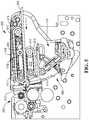
- FIG. 2illustrates transport pathways and modules within the ATM of FIG. 1 according to an embodiment of the present invention
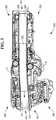
- FIG. 3illustrates a media item transport mechanism according to an embodiment of the present invention wherein the transport mechanism is in an infeed configuration for transporting a bunch of media items along an infeed transport path;
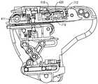
- FIG. 4illustrates a clamping mechanism of the media item transport mechanism of FIG. 3 when in the infeed position and aligned with a media item separator/feeder of the ATM of FIG. 2 ;
- FIG. 5illustrates the clamping mechanism of FIG. 4 applying a clamping force to a relatively thin bunch of media items
- FIG. 6illustrates further detail of the clamping mechanism of FIGS. 4 and 5 ;
- FIG. 7illustrates a displacement sensor of the clamping mechanism of FIGS. 4 to 6 ;
- FIG. 8illustrates an actuator mechanism of the clamping mechanism of FIGS. 4 to 7 for adjusting a clamp force applied to a bunch of media items by the clamping mechanism.
- FIG. 1illustrates a self-service check depositing terminal in the form of an image-based check depositing Automated Teller Machine (ATM) 100 .
- ATMAutomated Teller Machine
- FIG. 1illustrates a self-service check depositing terminal in the form of an image-based check depositing Automated Teller Machine (ATM) 100 .
- ATMAutomated Teller Machine
- FIG. 1illustrates a self-service check depositing terminal in the form of an image-based check depositing Automated Teller Machine (ATM) 100 .
- ATMAutomated Teller Machine
- the ATM 100includes a fascia 101 coupled to a chassis (not shown).
- the fascia 101defines an aperture 102 through which a camera (not shown) images a customer of the ATM 100 .
- the fascia 101also defines a number of slots for receiving and dispensing media items and a tray 103 into which coins can be dispensed.
- the slotsinclude a statement output slot 104 , a receipt slot 105 , a card reader slot 106 , a cash slot 107 , a further cash slot 108 and a check input/output slot 110 .
- the slots and trayare arranged such that the slots and tray align with corresponding ATM modules mounted within the chassis of the ATM.
- the fascia 101provides a customer interface for allowing an ATM customer to execute a transaction.
- the fascia 101includes an encrypting keyboard 120 for allowing an ATM customer to enter transaction details.
- a display 130is provided for presenting screens to an ATM customer.
- a fingerprint reader 140is provided for reading a fingerprint of an ATM customer to identify the ATM customer.
- FIG. 2illustrates possible transport pathways and internal modules within the ATM which can be utilized to process deposited checks.
- a check processing module 200has an access mouth 201 through which incoming checks and/or currency notes are deposited or outgoing checks are dispensed. This mouth 201 is aligned with an infeed aperture in the ATM which thus provides an input/output slot 110 .
- a bunch of one or more media items, such as currency notes or checks,is input or output. Aptly, a bunch of up to a hundred items or more can be received/dispensed.
- Incoming checksfollow a first transport path 202 away from the mouth 201 in a substantially horizontal direction from right to left shown in FIG. 2 .
- the first transport path 202is also referred to as the infeed path.
- the checksthen pass through a feeder/separator 203 and along another pathway portion 205 which is also substantially horizontal and right to left.
- the checksare then de-skewed and read by imaging cameras 206 and an MICR reader 207 .
- Checksare then directed substantially vertically downwards to a point between two nip rollers 208 .
- These nip rollersco-operate and are rotated in opposite directions with respect to each other to either draw deposited checks inwards (and urge those checks towards the right hand side in FIG. 2 ), or during another mode of operation, the rollers can be rotated in an opposite fashion to direct processed checks downwards in the direction shown by arrow A in FIG. 2 into a check bin 210 .
- Incoming checks which are moved by the nip rollers 208 towards the rightcan either be diverted upwards (in FIG. 2 ) into a re-buncher unit 225 , or downwards in the direction of arrow B in FIG. 2 into a cash bin 230 , or to the right hand side shown in FIG. 2 into an escrow 240 .
- Checks from the escrowcan be directed to the re-buncher 225 or downwards into the cash bin 230 .
- Checkscan be reprocessed or returned to a customer via a further transport path 204 , also known as the return path.
- a media item transport mechanism 300includes a first pair of opposed transport members 302 , 303 shown on the right-hand side of FIG. 3 and a second pair of opposed transport members 304 , 305 shown on the left-hand side of FIG. 3 .
- the pairs of transport membersprovide a predetermined transport path 202 , 204 for a bunch of media items 350 , such as checks or currency notes, to be urged along by the transport mechanism 300 .
- An infeed end region 301 of the first pair of transport members 302 , 303is located and aligned with the access mouth 201 of the check processing module 200 .
- the second pair of transport members 304 , 305pivots relative to the first pair of transport members 302 , 305 generally about axis A to selectively direct the bunch 350 along the infeed path 202 or return path 204 as desired. As shown in FIG. 3 , an end region 307 of the second pair of transport members 304 , 305 is aligned with the feeder/separator 203 when in the infeed position for single media items to be separated from the bunch 350 and individually processed by the processing module 200 .
- Each of the transport members 302 , 303 , 304 , 305includes at least one respective transport belt 306 , 308 , 310 , 312 for urging one or more media items along the transport path 202 , 204 .
- each transport membermay include a pair of spaced apart transport belts.
- rollers, gears, wheels, plates, or the like,may be used to urge one or more media items along the transport path 202 , 204 .
- Each pair of transport members 302 , 303 and 304 , 305are selectively moved towards or away from each other between closed and open configurations. This is achieved by moving one transport member towards or away from a fixed respective transport member or by moving both respective transport members towards or away from each other.
- a distance between a respective pair of belts of a respective transport member when in the open configurationis determined by the thickness of a bunch of media items to be or being transported through the transport mechanism 300 and along the transport path 202 , 204 .
- respective belts of a pair of transport memberswill be closer together when gripping and transporting a single media item and spaced further apart from each other when transporting a bunch of media items.
- the lower transport member 304 of the second pair of transport members 304 , 305 as shown in FIG. 3is rotatable about axis A with respect to the lower transport member 302 of the first pair of transport members 302 , 303 .
- the upper transport member 305 of the second pair of transport members 304 , 305is about axis C with respect to the upper transport member 303 of the first pair of transport members 302 , 303 .
- Axes A and Care located at respective end regions of the upper and lower transport members 302 , 303 of the first pair of transport members 302 , 303 .
- the lower transport member 304 of the second pair of transport members 304 , 305is rotatable with respect to the lower transport member 302 of the first pair of transport members 302 , 303 between an infeed position, wherein media items are moved from right to left (as shown in FIG. 3 ) through the transport mechanism 300 and along the infeed transport path 202 to be processed, and a return position, wherein media items are moved from left to right through the transport mechanism 300 and along the return transport path 204 to be reprocessed along the infeed path or returned to a customer.
- the second pair of transport members 304 , 305includes a clamping mechanism 380 for applying a predetermined clamp force to a bunch of media items 350 .
- the lower transport belt 310 of the lower transport member 304 of the second pair of transport members 304 , 305forms part of a moveable clamp member 410 (as best shown in FIG. 4 ) of the clamping mechanism 380 .
- the upper transport belt 312 of the upper transport member 305 of the second pair of transport members 304 , 305provides a support surface for engaging the bunch of media items 350 whilst a clamp force is applied to the bunch by the moveable clamp member 410 .
- the clamp member 410 of the clamping mechanism 380selectively moves towards or away from the upper transport belt 312 to respectively increase or decrease the clamp force applied to the bunch 350 responsive to a predetermined mode of operation of the ATM and/or a thickness of the bunch 350 , as will be described below.
- an end region of the second pair of transport members 304 , 305is aligned with an infeed opening 412 of the feeder/separator module 203 of the media processing module 200 which removes or adds one or more media items from or to the bunch of media items 350 respectively.
- the upper and lower transport belts 312 , 310 of the second pair of transport members 304 , 305urge the bunch of media items from right to left along the infeed path 202 (as indicated by arrow I) towards the infeed mouth 412 of the feeder/separator module 203 when the second pair of transport members 304 , 305 is in the infeed position, as shown in FIG. 4 .
- the upper and lower transport belts 312 , 310urge the bunch of media items 350 from left to right along the return path 204 to return the bunch to a customer or to re-process the bunch.
- the upper transport belt 312 of the second pair of transport members 304 , 305is supported by a pair of spaced apart rollers 411 , at least one of which is driven to selectively rotate the transport belt 312 in the infeed or return direction.
- the lower transport belt 310is supported on a pair of spaced apart rollers 414 of a moveable clamp member 410 of the clamping mechanism 380 , wherein at least one roller 414 is driven to selectively rotate the transport belt 310 in the infeed or return direction.
- the clamp member 410(and lower transport belt 310 ) is selectively moveable towards or away from the upper transport belt 312 of the upper transport member 305 by an actuator mechanism 416 to thereby selectively apply a clamp force to the bunch of media items 350 located between the upper and lower transport belts 312 , 310 .
- the upper transport belt 312acts as a support member against which the bunch 350 abuts when being compressed by the clamp member 410 .
- a predetermined clamp forceis applied to the bunch 350 by the clamping mechanism 380 to effectively transport the bunch along the infeed (or return) path 202 , 204 without the internals of the bunch shifting.
- a separation mode of operationas shown in FIG.
- an idler roller 418is located between the spaced part rollers 411 of the upper transport member 305 to engage with the upper transport belt 312 .
- the idler roller 418is biased by a leaf spring 420 towards the upper transport belt 312 to in turn urge the upper transport belt 312 towards the clamp member 410 .
- a bunch of media items 350moves from right to left to be located between the upper and lower transport belts 312 , 310 of the second pair of transport members 304 , 305 .
- the bunch 350When the bunch 350 is moved to a location proximal to the idler roller 420 , the bunch 350 counteracts the force exerted on the upper transport belt 312 by the idler roller 420 and the leaf spring 420 arrangement and forces the idler roller 418 away from clamp member 410 .
- the distance by which the idler roller 420 is moved away from the clamp member 410 by the bunch 350is dependent on the thickness of the bunch 350 . For example, as shown in FIG. 4 , a relatively thick bunch of media items 350 will displace the idler roller 420 by a greater amount than a relatively thin bunch of media items 350 as shown in FIG. 5 .
- the thickness of the bunch 350will decrease and the clamp member 410 is required to move towards the upper transport belt 312 to accommodate for this change in thickness in order to apply a predetermined clamping force on the bunch 350 .
- the thickness of the bunchwill increase and the clamp member 410 is required to move away from the upper transport belt 312 to accommodate for this change in thickness in order to apply a predetermined clamping force on the bunch 350 .
- a flag arm 710is attached to a shaft 419 of the idler roller 418 to thereby move with the idler roller 418 by a distance responsive to a thickness of the bunch of media items 350 .
- the flag arm 710blocks an optical interrupt sensor 712 by an amount which is dependent on the displacement of the flag arm 710 .
- the sensor 712sends a signal to a controller (not shown) of the ATM and the clamp member 410 (and lower transport belt 310 ) is moved towards or away from the upper transport belt 312 responsive to the displacement of the idler roller 418 and a thickness of the bunch 350 .
- the flag arm 710 and sensor 712 arrangementeffectively provides a feedback loop by automatically adjusting the position of the clamp member 410 relative to the upper transport belt 312 to apply a predetermined clamp force to the bunch of media items 350 responsive to a thickness of the bunch 350 .
- the clamp member 410 of the clamping mechanism 380is moved towards or away from the upper transport belt 312 by a stepper motor (not shown) which is coupled to the clamp member 410 by a scissor mechanism 810 .
- the scissor mechanism 810includes a pair of elongate scissor members 812 , 814 which are pivotally attached at respective central portions by a pivot member 816 .
- An upper end of the first scissor member 812is pivotally attached to the clamp member 410 and an upper end of the second scissor member 814 is slideably coupled to the clamp member 410 via a slot 820 of the clamp member 410 .
- a lower end of the first scissor member 812is slideably supported in a slot (not shown) of the lower transport member 304 of the second pair of transport members 304 , 305 and a lower end of the second scissor member 814 is pivotally attached to the lower transport member 304 of the pair of second transport members 304 , 305 .
- the lower end of the first scissor 812is urged towards the lower end of the second scissor member 814 (as indicated by arrow E) by an extension spring (not shown) to bias the clamp member 410 upwardly towards an extended position (as shown in FIG. 5 ).
- the stepper motorovercomes a force exerted by the extension spring to move the lower end of the first scissor member 812 away from the lower end of the second scissor member 814 (as indicated by arrow R) and move the clamp member 410 downwardly towards a retracted position (as shown in FIG. 4 ).
- the stepper motoris coupled to the lower end of the first scissor member 812 by a rack and pinion arrangement (not shown).
- the clamping mechanism 380therefore automatically moves a clamp member 410 supporting a lower transport belt 310 towards or away from an upper transport belt 312 responsive to a change in thickness of a bunch of media items 350 located between the upper and lower transport belts 310 , 312 to thereby ensure a predetermined clamp force applied to the bunch 350 by the clamp member 410 is constant for effectively removing or adding media items from or to the bunch 350 .
- the clamping mechanism 380according to certain embodiments of the present invention allows a predetermined clamp force to be applied to a bunch of media items 350 for effectively transporting the bunch along a predetermined transport path 202 , 204 .
- a first predetermined clamp forceis applied to the bunch 350 by the clamping mechanism 380 .
- a second predetermined clamp forcemay be applied to the bunch to allow for effective addition or removal of media items from the bunch.
- the second clamp forceis less than the first clamping force to enable much greater performance and efficiency for document separation and a lower fault rate.
- a higher first clamp force for document transportationalso prevents the bunch from becoming damaged or skewed when being transported and effectively grips the bunch of media items to be transported along the pre-determined transport path without the internal media items of the bunch shifting.
- the clamping mechanism 380provides a form of force feedback detect on a bunch of media items to automatically control a clamp force applied to the bunch by the clamping mechanism.
- the clamp member 410is free to compress or move downwardly against the extension spring whilst a compression on the bunch can be measured by the optical sensor which is at least partially blocked by the flag arm responsive to a displacement of the idler roller which itself urges the upper transport belt against the bunch.
- the clamping mechanismaccording to certain embodiments of the present invention thereby allows the bunch to be compressed to a controlled light compression force during the infeed mode of operation, whilst also allowing the extension spring of the clamping mechanism to apply a larger compression force on the bunch during a transport mode of operation.
- the clamping mechanismis space conservative, stable, simple, low cost and accurate.
- the sensor flagmay be incorporated into the existing drive system of the upper transport member 305 of the second pair of transport members 304 , 305 of the transport mechanism 300 which enables accurate compression feedback for any form of bunch.
- the optical sensorrequires no calibration and is repeatable on different media item processing modules.
Landscapes
- Engineering & Computer Science (AREA)
- Mechanical Engineering (AREA)
- Physics & Mathematics (AREA)
- General Physics & Mathematics (AREA)
- Delivering By Means Of Belts And Rollers (AREA)
Abstract
Description
- locating a bunch of media items between at least one support surface and at least one clamp member; and
- selectively moving said clamp member towards or away from said support surface to apply a predetermined clamp force to the bunch of media items.
- determining a thickness associated with the bunch of media items; and
- selectively moving said clamp member towards or away from said support surface responsive to the thickness.
- removing or adding a media item from or to the bunch of media items to respectively decrease or increase said thickness of the bunch of media items and moving the clamp member to maintain a pre-determined clamp force as the thickness is decreased or increased.
- determining said thickness of the bunch of media items by sensing a displacement of a moveable element that is moveable towards or away from the clamp member responsive to said thickness of the bunch of media items; and
- selectively moving the clamp member towards or away from the support surface to apply the predetermined clamp force to the bunch of media items responsive to a displacement of the moveable element.
- biasing said moveable element towards said clamp member.
- at least one clamp member to apply a clamp force to a bunch of media items located between a support surface and said clamp member; wherein
- said clamp member is selectively moveable towards or away from said support surface to apply a predetermined clamp force to the bunch of media items.
- at least one moveable element moveable towards or away from said clamp member responsive to a thickness associated with the bunch of media items, wherein said clamp member is selectively moved towards or away from said support surface responsive to said thickness.
- at least one sensor to sense a displacement of the moveable element towards or away from the clamp member.
- at least one target element associated with the moveable element;
- wherein
- the at least one sensor comprises an optical displacement sensor that determines a location of said target element responsive to said displacement of the moveable element.
- at least one transport belt for locating the bunch of media items, wherein an outer drive surface of said transport belt further comprises said support surface.
- a biasing member that constantly biases the clamp member towards the support surface; and
- an actuator that selectively locates a portion of the clamp member to at least partially counteract the constant biasing to selectively move the clamp member at least partially away from the support surface.
- clamping a bunch of media items between a clamp member and a support surface, wherein a clamp force applied by the clamp member in a first mode of operation is greater than a clamp force applied by the clamp member in a further mode of operation when at least one media item is to be removed from or added to the bunch.
Claims (14)
Priority Applications (3)
| Application Number | Priority Date | Filing Date | Title |
|---|---|---|---|
| US13/959,271US10504315B2 (en) | 2013-08-05 | 2013-08-05 | Clamping of media items |
| EP14173073.9AEP2835330B1 (en) | 2013-08-05 | 2014-06-19 | Clamping of media items |
| CN201410377429.2ACN104346880B (en) | 2013-08-05 | 2014-08-01 | Clamp medium |
Applications Claiming Priority (1)
| Application Number | Priority Date | Filing Date | Title |
|---|---|---|---|
| US13/959,271US10504315B2 (en) | 2013-08-05 | 2013-08-05 | Clamping of media items |
Publications (2)
| Publication Number | Publication Date |
|---|---|
| US20150034457A1 US20150034457A1 (en) | 2015-02-05 |
| US10504315B2true US10504315B2 (en) | 2019-12-10 |
Family
ID=50972566
Family Applications (1)
| Application Number | Title | Priority Date | Filing Date |
|---|---|---|---|
| US13/959,271Active2033-10-07US10504315B2 (en) | 2013-08-05 | 2013-08-05 | Clamping of media items |
Country Status (3)
| Country | Link |
|---|---|
| US (1) | US10504315B2 (en) |
| EP (1) | EP2835330B1 (en) |
| CN (1) | CN104346880B (en) |
Cited By (2)
| Publication number | Priority date | Publication date | Assignee | Title |
|---|---|---|---|---|
| US20230053610A1 (en)* | 2020-01-15 | 2023-02-23 | Shandong New Beiyang Information Technolgy Co., Ltd. | Control Method for Banknote Accumulation Device, and Device and Cash Processing Apparatus |
| US20250095428A1 (en)* | 2021-07-28 | 2025-03-20 | Crane Payment Innovations, Inc. | Multi-mode bulk banknote feeder |
Families Citing this family (6)
| Publication number | Priority date | Publication date | Assignee | Title |
|---|---|---|---|---|
| JP6291254B2 (en) | 2011-10-28 | 2018-03-14 | 中外製薬株式会社 | Cancer stem cell specific molecule |
| CN104361678B (en)* | 2014-10-22 | 2017-03-29 | 华南农业大学 | A kind of experimental provision of currency counting and detecting machine crosses paper money kinestate visual research |
| US9754434B2 (en)* | 2015-05-29 | 2017-09-05 | Diebold, Inc. | Moveable platen in document handling systems for an automated teller machine |
| US10472191B2 (en) | 2016-07-28 | 2019-11-12 | Ncr Corporation | Adaptive pressure media feeding |
| JP2022027100A (en)* | 2020-07-31 | 2022-02-10 | グローリー株式会社 | Check processing device |
| JP7408511B2 (en) | 2020-09-02 | 2024-01-05 | 東芝テック株式会社 | Sheet conveyance device |
Citations (39)
| Publication number | Priority date | Publication date | Assignee | Title |
|---|---|---|---|---|
| US3749395A (en) | 1972-06-14 | 1973-07-31 | Olivetti & Co Spa | Device for feeding and sorting documents |
| US3972157A (en)* | 1975-03-24 | 1976-08-03 | Sanford Meyers | Bag holding and opening apparatus |
| US4320854A (en)* | 1978-07-26 | 1982-03-23 | Tokyo Shibaura Denki Kabushiki Kaisha | Automatic cash issue machine |
| GB2123592A (en) | 1982-07-12 | 1984-02-01 | Tokyo Shibaura Electric Co | Automatic bank note transaction apparatus |
| US4546857A (en)* | 1983-07-21 | 1985-10-15 | Kumahira Safe Co., Inc. | Conveyor system for a drive-in bank |
| US4616817A (en)* | 1983-05-09 | 1986-10-14 | Kabushiki Kaisha Toshiba | Paper sheet dispensing apparatus |
| US4733765A (en)* | 1985-11-14 | 1988-03-29 | Kabushiki Kaisha Toshiba | Cash handling machine for handling mixtures of notes and coins introduced together |
| US4765607A (en)* | 1985-03-08 | 1988-08-23 | Mars, Incorporated | Stacker apparatus |
| US4980543A (en)* | 1983-01-26 | 1990-12-25 | Tokyo Shibaura Denki Kabushiki Kaisha | Multiple denominator bank note depositor/dispenser with automatic loading to and from storage section |
| US5058880A (en)* | 1990-08-17 | 1991-10-22 | Xerox Corporation | Disk stacker including wiping member for registration assist |
| US5106077A (en)* | 1989-03-06 | 1992-04-21 | Hitachi, Ltd. | Paper conveying, discharging and recovering mechanism |
| US6164638A (en)* | 1997-11-28 | 2000-12-26 | Dicbold, Incorporates | Automated banking machine with currency recycling canisters |
| US6173607B1 (en)* | 1998-01-22 | 2001-01-16 | Opsigal Control Systems Ltd. | System and method for counting the number of items within a stack |
| US20010045697A1 (en)* | 2000-02-09 | 2001-11-29 | Jerome Daout | Self aligning transport mechanism for media of variable media widths |
| JP2002329229A (en) | 2001-05-07 | 2002-11-15 | Mamiya Op Co Ltd | Bill receiving / dispensing device |
| US20030089769A1 (en)* | 2001-10-09 | 2003-05-15 | Gregory Jantsch | Dispensing of currency |
| US20030094402A1 (en)* | 2001-11-22 | 2003-05-22 | Yoshimasa Seo | Bill deposit machine |
| US20030132568A1 (en)* | 2001-12-20 | 2003-07-17 | Guillermo Garcia | Value sheet handling apparatus |
| US20060067559A1 (en)* | 2002-12-24 | 2006-03-30 | Donders Paulina T G | Method of analysing a stack of flat objects |
| US20060225986A1 (en)* | 2005-04-08 | 2006-10-12 | Laurel Precision Machines Co., Ltd. | Paper sheet storage and payout device |
| US20070007707A1 (en)* | 2004-03-15 | 2007-01-11 | Fujitsu Limited | Paper sheet handling device |
| US20070034683A1 (en)* | 2005-07-01 | 2007-02-15 | Diebold Self-Service Systems | ATM that can center different sized cash stack in a cash outlet opening |
| US20070045396A1 (en)* | 2005-08-31 | 2007-03-01 | Naofumi Kitagawa | Paper stacking apparatus |
| US20070182090A1 (en)* | 2005-07-27 | 2007-08-09 | Andre Gerlier | Banknote handling |
| US20070267488A1 (en)* | 2006-05-19 | 2007-11-22 | International Currncy Technologies Corporation | Card dispenser having a mobile sensor holder box |
| EP1926057A1 (en) | 2006-11-24 | 2008-05-28 | Hitachi-Omron Terminal Solutions, Corp. | Bill depositing/withdrawing apparatus and method of controlling the same |
| US20090206541A1 (en)* | 2008-01-30 | 2009-08-20 | Nuetzel Dominik | Apparatus for singling of sheet material |
| DE102008030878A1 (en) | 2008-06-30 | 2009-12-31 | Giesecke & Devrient Gmbh | Apparatus and method for accepting or dispensing banknotes |
| US20100042254A1 (en)* | 2006-08-18 | 2010-02-18 | Van Heek Helmut | Method of feeding flattened cardboard cartons in a carton opening machine in a bottle, container, or article packaging plant, and a device therefor |
| US20100052237A1 (en)* | 2006-10-18 | 2010-03-04 | Lars Karoly Herczeg | Document handling apparatus |
| US20100125515A1 (en)* | 2008-11-14 | 2010-05-20 | Glory Ltd., A Corporation Of Japan | Fund management system |
| US20110031308A1 (en)* | 2008-04-15 | 2011-02-10 | Wincor Nixdorf International Gmbh | Device for handling single sheets, for introducing and distributing rectangular single sheets, especially bank notes, respectively into and out of a container |
| JP2011079596A (en) | 2009-10-03 | 2011-04-21 | Oki Electric Industry Co Ltd | Paper sheet separating carrying device |
| US20110187038A1 (en)* | 2005-08-11 | 2011-08-04 | Heise Jens U | Device for depositing for a printing machine |
| US20120007304A1 (en)* | 2010-07-08 | 2012-01-12 | Ncr Corporation | Media depository |
| JP2012038355A (en) | 2011-11-24 | 2012-02-23 | Hitachi Omron Terminal Solutions Corp | Paper money payment/reception device |
| US20140151272A1 (en)* | 2012-11-30 | 2014-06-05 | Ncr Corporation | Media item characterization |
| CN104346859A (en) | 2013-07-30 | 2015-02-11 | Ncr公司 | Media item transportation |
| US20150136562A1 (en)* | 2012-05-14 | 2015-05-21 | Hitachi-Omron Terminal Solutions, Corporation | Paper-slip handling device and automated transaction device |
Family Cites Families (1)
| Publication number | Priority date | Publication date | Assignee | Title |
|---|---|---|---|---|
| CN102324138B (en)* | 2011-09-08 | 2013-11-06 | 广州广电运通金融电子股份有限公司 | Paper sheet stacking and recycling device and paper sheet processing equipment with same |
- 2013
- 2013-08-05USUS13/959,271patent/US10504315B2/enactiveActive
- 2014
- 2014-06-19EPEP14173073.9Apatent/EP2835330B1/enactiveActive
- 2014-08-01CNCN201410377429.2Apatent/CN104346880B/enactiveActive
Patent Citations (48)
| Publication number | Priority date | Publication date | Assignee | Title |
|---|---|---|---|---|
| US3749395A (en) | 1972-06-14 | 1973-07-31 | Olivetti & Co Spa | Device for feeding and sorting documents |
| US3972157A (en)* | 1975-03-24 | 1976-08-03 | Sanford Meyers | Bag holding and opening apparatus |
| US4320854A (en)* | 1978-07-26 | 1982-03-23 | Tokyo Shibaura Denki Kabushiki Kaisha | Automatic cash issue machine |
| GB2123592A (en) | 1982-07-12 | 1984-02-01 | Tokyo Shibaura Electric Co | Automatic bank note transaction apparatus |
| US4571489A (en) | 1982-07-12 | 1986-02-18 | Tokyo Shibaura Denki Kabushiki Kaisha | Automatic bank note transaction apparatus |
| US4980543A (en)* | 1983-01-26 | 1990-12-25 | Tokyo Shibaura Denki Kabushiki Kaisha | Multiple denominator bank note depositor/dispenser with automatic loading to and from storage section |
| US4616817A (en)* | 1983-05-09 | 1986-10-14 | Kabushiki Kaisha Toshiba | Paper sheet dispensing apparatus |
| US4546857A (en)* | 1983-07-21 | 1985-10-15 | Kumahira Safe Co., Inc. | Conveyor system for a drive-in bank |
| US4765607A (en)* | 1985-03-08 | 1988-08-23 | Mars, Incorporated | Stacker apparatus |
| US4733765A (en)* | 1985-11-14 | 1988-03-29 | Kabushiki Kaisha Toshiba | Cash handling machine for handling mixtures of notes and coins introduced together |
| US5106077A (en)* | 1989-03-06 | 1992-04-21 | Hitachi, Ltd. | Paper conveying, discharging and recovering mechanism |
| US5058880A (en)* | 1990-08-17 | 1991-10-22 | Xerox Corporation | Disk stacker including wiping member for registration assist |
| US6164638A (en)* | 1997-11-28 | 2000-12-26 | Dicbold, Incorporates | Automated banking machine with currency recycling canisters |
| US6173607B1 (en)* | 1998-01-22 | 2001-01-16 | Opsigal Control Systems Ltd. | System and method for counting the number of items within a stack |
| US20010045697A1 (en)* | 2000-02-09 | 2001-11-29 | Jerome Daout | Self aligning transport mechanism for media of variable media widths |
| JP2002329229A (en) | 2001-05-07 | 2002-11-15 | Mamiya Op Co Ltd | Bill receiving / dispensing device |
| US20030089769A1 (en)* | 2001-10-09 | 2003-05-15 | Gregory Jantsch | Dispensing of currency |
| US20030094402A1 (en)* | 2001-11-22 | 2003-05-22 | Yoshimasa Seo | Bill deposit machine |
| US20030132568A1 (en)* | 2001-12-20 | 2003-07-17 | Guillermo Garcia | Value sheet handling apparatus |
| US20060067559A1 (en)* | 2002-12-24 | 2006-03-30 | Donders Paulina T G | Method of analysing a stack of flat objects |
| CN1926586A (en) | 2004-03-15 | 2007-03-07 | 富士通株式会社 | Sheet handler |
| US20070007707A1 (en)* | 2004-03-15 | 2007-01-11 | Fujitsu Limited | Paper sheet handling device |
| US20060225986A1 (en)* | 2005-04-08 | 2006-10-12 | Laurel Precision Machines Co., Ltd. | Paper sheet storage and payout device |
| US20070034683A1 (en)* | 2005-07-01 | 2007-02-15 | Diebold Self-Service Systems | ATM that can center different sized cash stack in a cash outlet opening |
| US20070182090A1 (en)* | 2005-07-27 | 2007-08-09 | Andre Gerlier | Banknote handling |
| US20110187038A1 (en)* | 2005-08-11 | 2011-08-04 | Heise Jens U | Device for depositing for a printing machine |
| US20070045396A1 (en)* | 2005-08-31 | 2007-03-01 | Naofumi Kitagawa | Paper stacking apparatus |
| US20070267488A1 (en)* | 2006-05-19 | 2007-11-22 | International Currncy Technologies Corporation | Card dispenser having a mobile sensor holder box |
| US20100042254A1 (en)* | 2006-08-18 | 2010-02-18 | Van Heek Helmut | Method of feeding flattened cardboard cartons in a carton opening machine in a bottle, container, or article packaging plant, and a device therefor |
| US20100052237A1 (en)* | 2006-10-18 | 2010-03-04 | Lars Karoly Herczeg | Document handling apparatus |
| EP1926057A1 (en) | 2006-11-24 | 2008-05-28 | Hitachi-Omron Terminal Solutions, Corp. | Bill depositing/withdrawing apparatus and method of controlling the same |
| US20080142583A1 (en)* | 2006-11-24 | 2008-06-19 | Toshinori Yokoi | Bill depositing/withdrawing apparatus and method of controlling the same |
| US20090206541A1 (en)* | 2008-01-30 | 2009-08-20 | Nuetzel Dominik | Apparatus for singling of sheet material |
| US7883088B2 (en)* | 2008-01-30 | 2011-02-08 | Giesecke & Devrient Gmbh | Apparatus for singling of sheet material |
| US20110031308A1 (en)* | 2008-04-15 | 2011-02-10 | Wincor Nixdorf International Gmbh | Device for handling single sheets, for introducing and distributing rectangular single sheets, especially bank notes, respectively into and out of a container |
| US20100025308A1 (en)* | 2008-06-30 | 2010-02-04 | Dominik Nutzel | Apparatus and method for accepting or dispensing bank notes |
| DE102008030878A1 (en) | 2008-06-30 | 2009-12-31 | Giesecke & Devrient Gmbh | Apparatus and method for accepting or dispensing banknotes |
| US8167135B2 (en)* | 2008-06-30 | 2012-05-01 | Giesecke & Devrient Gmbh | Apparatus and method for accepting or dispensing bank notes |
| US20100125515A1 (en)* | 2008-11-14 | 2010-05-20 | Glory Ltd., A Corporation Of Japan | Fund management system |
| CN102030208A (en) | 2009-10-03 | 2011-04-27 | 冲电气工业株式会社 | Paper separating and conveying apparatus |
| JP2011079596A (en) | 2009-10-03 | 2011-04-21 | Oki Electric Industry Co Ltd | Paper sheet separating carrying device |
| US20120007304A1 (en)* | 2010-07-08 | 2012-01-12 | Ncr Corporation | Media depository |
| US8262076B2 (en)* | 2010-07-08 | 2012-09-11 | Ncr Corporation | Media depository |
| JP2012038355A (en) | 2011-11-24 | 2012-02-23 | Hitachi Omron Terminal Solutions Corp | Paper money payment/reception device |
| US20150136562A1 (en)* | 2012-05-14 | 2015-05-21 | Hitachi-Omron Terminal Solutions, Corporation | Paper-slip handling device and automated transaction device |
| US20140151272A1 (en)* | 2012-11-30 | 2014-06-05 | Ncr Corporation | Media item characterization |
| CN104346859A (en) | 2013-07-30 | 2015-02-11 | Ncr公司 | Media item transportation |
| US9016683B2 (en) | 2013-07-30 | 2015-04-28 | Ncr Corporation | Media item transportation |
Cited By (2)
| Publication number | Priority date | Publication date | Assignee | Title |
|---|---|---|---|---|
| US20230053610A1 (en)* | 2020-01-15 | 2023-02-23 | Shandong New Beiyang Information Technolgy Co., Ltd. | Control Method for Banknote Accumulation Device, and Device and Cash Processing Apparatus |
| US20250095428A1 (en)* | 2021-07-28 | 2025-03-20 | Crane Payment Innovations, Inc. | Multi-mode bulk banknote feeder |
Also Published As
| Publication number | Publication date |
|---|---|
| CN104346880B (en) | 2017-09-01 |
| EP2835330A1 (en) | 2015-02-11 |
| EP2835330B1 (en) | 2019-08-07 |
| US20150034457A1 (en) | 2015-02-05 |
| CN104346880A (en) | 2015-02-11 |
Similar Documents
| Publication | Publication Date | Title |
|---|---|---|
| US10504315B2 (en) | Clamping of media items | |
| EP2832673B1 (en) | Apparatus for transporting an item of media, media item processing module, and method of transporting an item of media | |
| CN101520913B (en) | Paper transport mechanism and paper handling device | |
| CN103426231B (en) | Bill handling device and automatic trading apparatus | |
| US8944433B2 (en) | Method for handling valuable documents having an aligning unit for aligning banknotes and checks | |
| US8113511B2 (en) | Document deskewing module with a moving track bottom and methods of operating a document deskewing module | |
| EP2287099B1 (en) | Document Deskewing | |
| EP2565856B1 (en) | Apparatus for pulling bills and checks in bundle bill and check acceptor | |
| EP2832672B1 (en) | Method and apparatus for media item transportation | |
| US8931613B2 (en) | Device for handling notes of value, comprising a stack merging unit | |
| US9472041B2 (en) | Clamping of media items | |
| CN103778708A (en) | Paper sheet handling device with transport unit | |
| CN104077853A (en) | Paper sheet handling device and automatic transaction device | |
| CN103426230B (en) | Bill handling device and automatic trading apparatus | |
| US9171430B2 (en) | Media item transporter | |
| US10543998B2 (en) | Apparatus for aligning notes of value | |
| US9990793B2 (en) | Media item separation | |
| US9302876B2 (en) | Media presenter | |
| KR101678892B1 (en) | Cassette apparatus of various bills | |
| JP4211634B2 (en) | Bill recognition device | |
| KR101472067B1 (en) | Bundle pickup device for media paper processing machine | |
| US10082476B2 (en) | Sensing of media items | |
| JP2019144787A (en) | Medium processor and medium transaction device |
Legal Events
| Date | Code | Title | Description |
|---|---|---|---|
| AS | Assignment | Owner name:NCR CORPORATION, GEORGIA Free format text:ASSIGNMENT OF ASSIGNORS INTEREST;ASSIGNORS:DUNN, FRANK B.;SONNENBERG, MATTHEW;REEL/FRAME:030943/0669 Effective date:20130717 | |
| AS | Assignment | Owner name:JPMORGAN CHASE BANK, N.A., AS ADMINISTRATIVE AGENT, ILLINOIS Free format text:SECURITY AGREEMENT;ASSIGNORS:NCR CORPORATION;NCR INTERNATIONAL, INC.;REEL/FRAME:032034/0010 Effective date:20140106 Owner name:JPMORGAN CHASE BANK, N.A., AS ADMINISTRATIVE AGENT Free format text:SECURITY AGREEMENT;ASSIGNORS:NCR CORPORATION;NCR INTERNATIONAL, INC.;REEL/FRAME:032034/0010 Effective date:20140106 | |
| AS | Assignment | Owner name:JPMORGAN CHASE BANK, N.A., ILLINOIS Free format text:SECURITY AGREEMENT;ASSIGNORS:NCR CORPORATION;NCR INTERNATIONAL, INC.;REEL/FRAME:038646/0001 Effective date:20160331 | |
| STPP | Information on status: patent application and granting procedure in general | Free format text:FINAL REJECTION MAILED | |
| STPP | Information on status: patent application and granting procedure in general | Free format text:ADVISORY ACTION MAILED | |
| STPP | Information on status: patent application and granting procedure in general | Free format text:DOCKETED NEW CASE - READY FOR EXAMINATION | |
| STPP | Information on status: patent application and granting procedure in general | Free format text:NOTICE OF ALLOWANCE MAILED -- APPLICATION RECEIVED IN OFFICE OF PUBLICATIONS | |
| STCF | Information on status: patent grant | Free format text:PATENTED CASE | |
| MAFP | Maintenance fee payment | Free format text:PAYMENT OF MAINTENANCE FEE, 4TH YEAR, LARGE ENTITY (ORIGINAL EVENT CODE: M1551); ENTITY STATUS OF PATENT OWNER: LARGE ENTITY Year of fee payment:4 | |
| AS | Assignment | Owner name:CITIBANK, N.A., NEW YORK Free format text:SECURITY INTEREST;ASSIGNOR:NCR ATLEOS CORPORATION;REEL/FRAME:065331/0297 Effective date:20230927 | |
| AS | Assignment | Owner name:NCR VOYIX CORPORATION, GEORGIA Free format text:RELEASE OF PATENT SECURITY INTEREST;ASSIGNOR:JPMORGAN CHASE BANK, N.A., AS ADMINISTRATIVE AGENT;REEL/FRAME:065346/0531 Effective date:20231016 Owner name:BANK OF AMERICA, N.A., AS ADMINISTRATIVE AGENT, NORTH CAROLINA Free format text:SECURITY INTEREST;ASSIGNORS:NCR ATLEOS CORPORATION;CARDTRONICS USA, LLC;REEL/FRAME:065346/0367 Effective date:20231016 | |
| AS | Assignment | Owner name:CITIBANK, N.A., NEW YORK Free format text:CORRECTIVE ASSIGNMENT TO CORRECT THE DOCUMENT DATE AND REMOVE THE OATH/DECLARATION (37 CFR 1.63) PREVIOUSLY RECORDED AT REEL: 065331 FRAME: 0297. ASSIGNOR(S) HEREBY CONFIRMS THE SECURITY INTEREST;ASSIGNOR:NCR ATLEOS CORPORATION;REEL/FRAME:065627/0332 Effective date:20231016 | |
| AS | Assignment | Owner name:NCR VOYIX CORPORATION, GEORGIA Free format text:CHANGE OF NAME;ASSIGNOR:NCR CORPORATION;REEL/FRAME:067578/0417 Effective date:20231013 Owner name:NCR ATLEOS CORPORATION, GEORGIA Free format text:ASSIGNMENT OF ASSIGNORS INTEREST;ASSIGNOR:NCR VOYIX CORPORATION;REEL/FRAME:067590/0109 Effective date:20231016 | |
| AS | Assignment | Owner name:BANK OF AMERICA, N.A., AS ADMINISTRATIVE AGENT, NORTH CAROLINA Free format text:CORRECTIVE ASSIGNMENT TO CORRECT THE THE PROPERTIES SECTION BY INCLUDING IT WITH TEN PREVIOUSLY OMITTED PROPERTY NUMBERS PREVIOUSLY RECORDED ON REEL 65346 FRAME 367. ASSIGNOR(S) HEREBY CONFIRMS THE SECURITY INTEREST;ASSIGNORS:NCR ATLEOS CORPORATION;CARDTRONICS USA, LLC;REEL/FRAME:072445/0072 Effective date:20231016 |