US10501226B2 - Modular carton - Google Patents
Modular cartonDownload PDFInfo
- Publication number
- US10501226B2 US10501226B2US15/992,607US201815992607AUS10501226B2US 10501226 B2US10501226 B2US 10501226B2US 201815992607 AUS201815992607 AUS 201815992607AUS 10501226 B2US10501226 B2US 10501226B2
- Authority
- US
- United States
- Prior art keywords
- side panel
- upper portion
- divider
- carton
- panel
- Prior art date
- Legal status (The legal status is an assumption and is not a legal conclusion. Google has not performed a legal analysis and makes no representation as to the accuracy of the status listed.)
- Active
Links
- 238000000034methodMethods0.000claimsdescription15
- 239000000853adhesiveSubstances0.000claimsdescription9
- 230000001070adhesive effectEffects0.000claimsdescription9
- 238000000926separation methodMethods0.000claimsdescription3
- 239000000463materialSubstances0.000description13
- 230000002787reinforcementEffects0.000description12
- 235000013361beverageNutrition0.000description11
- 239000003292glueSubstances0.000description6
- 230000008901benefitEffects0.000description5
- 238000012986modificationMethods0.000description3
- 230000004048modificationEffects0.000description3
- 230000003014reinforcing effectEffects0.000description3
- 229910052782aluminiumInorganic materials0.000description2
- XAGFODPZIPBFFR-UHFFFAOYSA-NaluminiumChemical compound[Al]XAGFODPZIPBFFR-UHFFFAOYSA-N0.000description2
- 239000004927claySubstances0.000description2
- 239000011248coating agentSubstances0.000description2
- 238000000576coating methodMethods0.000description2
- 238000004806packaging method and processMethods0.000description2
- 230000003313weakening effectEffects0.000description2
- VGGSQFUCUMXWEO-UHFFFAOYSA-NEtheneChemical compoundC=CVGGSQFUCUMXWEO-UHFFFAOYSA-N0.000description1
- 229920000219Ethylene vinyl alcoholPolymers0.000description1
- 239000004677NylonSubstances0.000description1
- 239000004743PolypropyleneSubstances0.000description1
- 239000004793PolystyreneSubstances0.000description1
- 238000007792additionMethods0.000description1
- 238000004026adhesive bondingMethods0.000description1
- 230000004888barrier functionEffects0.000description1
- 239000011111cardboardSubstances0.000description1
- 230000000994depressogenic effectEffects0.000description1
- UFRKOOWSQGXVKV-UHFFFAOYSA-Nethene;ethenolChemical compoundC=C.OC=CUFRKOOWSQGXVKV-UHFFFAOYSA-N0.000description1
- 239000004715ethylene vinyl alcoholSubstances0.000description1
- 239000011521glassSubstances0.000description1
- 229920001903high density polyethylenePolymers0.000description1
- 239000004700high-density polyethyleneSubstances0.000description1
- 230000000977initiatory effectEffects0.000description1
- 229920000092linear low density polyethylenePolymers0.000description1
- 239000004707linear low-density polyethyleneSubstances0.000description1
- 229920001684low density polyethylenePolymers0.000description1
- 239000004702low-density polyethyleneSubstances0.000description1
- 229910052751metalInorganic materials0.000description1
- 239000002184metalSubstances0.000description1
- 150000002739metalsChemical class0.000description1
- 239000000203mixtureSubstances0.000description1
- 229920001778nylonPolymers0.000description1
- 239000000123paperSubstances0.000description1
- 239000011087paperboardSubstances0.000description1
- 230000002093peripheral effectEffects0.000description1
- 239000004033plasticSubstances0.000description1
- 229920003023plasticPolymers0.000description1
- 229920000139polyethylene terephthalatePolymers0.000description1
- 239000005020polyethylene terephthalateSubstances0.000description1
- 229920000915polyvinyl chloridePolymers0.000description1
- 239000004800polyvinyl chlorideSubstances0.000description1
- 239000002966varnishSubstances0.000description1
Images


Classifications
- B—PERFORMING OPERATIONS; TRANSPORTING
- B65—CONVEYING; PACKING; STORING; HANDLING THIN OR FILAMENTARY MATERIAL
- B65D—CONTAINERS FOR STORAGE OR TRANSPORT OF ARTICLES OR MATERIALS, e.g. BAGS, BARRELS, BOTTLES, BOXES, CANS, CARTONS, CRATES, DRUMS, JARS, TANKS, HOPPERS, FORWARDING CONTAINERS; ACCESSORIES, CLOSURES, OR FITTINGS THEREFOR; PACKAGING ELEMENTS; PACKAGES
- B65D5/00—Rigid or semi-rigid containers of polygonal cross-section, e.g. boxes, cartons or trays, formed by folding or erecting one or more blanks made of paper
- B65D5/42—Details of containers or of foldable or erectable container blanks
- B65D5/44—Integral, inserted or attached portions forming internal or external fittings
- B65D5/46—Handles
- B65D5/46072—Handles integral with the container
- B65D5/4608—Handgrip holes
- B—PERFORMING OPERATIONS; TRANSPORTING
- B65—CONVEYING; PACKING; STORING; HANDLING THIN OR FILAMENTARY MATERIAL
- B65D—CONTAINERS FOR STORAGE OR TRANSPORT OF ARTICLES OR MATERIALS, e.g. BAGS, BARRELS, BOTTLES, BOXES, CANS, CARTONS, CRATES, DRUMS, JARS, TANKS, HOPPERS, FORWARDING CONTAINERS; ACCESSORIES, CLOSURES, OR FITTINGS THEREFOR; PACKAGING ELEMENTS; PACKAGES
- B65D5/00—Rigid or semi-rigid containers of polygonal cross-section, e.g. boxes, cartons or trays, formed by folding or erecting one or more blanks made of paper
- B65D5/02—Rigid or semi-rigid containers of polygonal cross-section, e.g. boxes, cartons or trays, formed by folding or erecting one or more blanks made of paper by folding or erecting a single blank to form a tubular body with or without subsequent folding operations, or the addition of separate elements, to close the ends of the body
- B65D5/0227—Rigid or semi-rigid containers of polygonal cross-section, e.g. boxes, cartons or trays, formed by folding or erecting one or more blanks made of paper by folding or erecting a single blank to form a tubular body with or without subsequent folding operations, or the addition of separate elements, to close the ends of the body with end closures formed by inward folding of flaps and securing them by heat-sealing, by applying adhesive to the flaps or by staples
- B—PERFORMING OPERATIONS; TRANSPORTING
- B65—CONVEYING; PACKING; STORING; HANDLING THIN OR FILAMENTARY MATERIAL
- B65D—CONTAINERS FOR STORAGE OR TRANSPORT OF ARTICLES OR MATERIALS, e.g. BAGS, BARRELS, BOTTLES, BOXES, CANS, CARTONS, CRATES, DRUMS, JARS, TANKS, HOPPERS, FORWARDING CONTAINERS; ACCESSORIES, CLOSURES, OR FITTINGS THEREFOR; PACKAGING ELEMENTS; PACKAGES
- B65D5/00—Rigid or semi-rigid containers of polygonal cross-section, e.g. boxes, cartons or trays, formed by folding or erecting one or more blanks made of paper
- B65D5/42—Details of containers or of foldable or erectable container blanks
- B65D5/44—Integral, inserted or attached portions forming internal or external fittings
- B65D5/48—Partitions
- B65D5/48024—Partitions inserted
- B—PERFORMING OPERATIONS; TRANSPORTING
- B65—CONVEYING; PACKING; STORING; HANDLING THIN OR FILAMENTARY MATERIAL
- B65D—CONTAINERS FOR STORAGE OR TRANSPORT OF ARTICLES OR MATERIALS, e.g. BAGS, BARRELS, BOTTLES, BOXES, CANS, CARTONS, CRATES, DRUMS, JARS, TANKS, HOPPERS, FORWARDING CONTAINERS; ACCESSORIES, CLOSURES, OR FITTINGS THEREFOR; PACKAGING ELEMENTS; PACKAGES
- B65D5/00—Rigid or semi-rigid containers of polygonal cross-section, e.g. boxes, cartons or trays, formed by folding or erecting one or more blanks made of paper
- B65D5/42—Details of containers or of foldable or erectable container blanks
- B65D5/54—Lines of weakness to facilitate opening of container or dividing it into separate parts by cutting or tearing
- B65D5/5405—Lines of weakness to facilitate opening of container or dividing it into separate parts by cutting or tearing for opening containers formed by erecting a blank in tubular form
- B65D5/541—Lines of weakness to facilitate opening of container or dividing it into separate parts by cutting or tearing for opening containers formed by erecting a blank in tubular form the lines of weakness being provided in one or more closure flaps
- B—PERFORMING OPERATIONS; TRANSPORTING
- B65—CONVEYING; PACKING; STORING; HANDLING THIN OR FILAMENTARY MATERIAL
- B65D—CONTAINERS FOR STORAGE OR TRANSPORT OF ARTICLES OR MATERIALS, e.g. BAGS, BARRELS, BOTTLES, BOXES, CANS, CARTONS, CRATES, DRUMS, JARS, TANKS, HOPPERS, FORWARDING CONTAINERS; ACCESSORIES, CLOSURES, OR FITTINGS THEREFOR; PACKAGING ELEMENTS; PACKAGES
- B65D5/00—Rigid or semi-rigid containers of polygonal cross-section, e.g. boxes, cartons or trays, formed by folding or erecting one or more blanks made of paper
- B65D5/42—Details of containers or of foldable or erectable container blanks
- B65D5/54—Lines of weakness to facilitate opening of container or dividing it into separate parts by cutting or tearing
- B65D5/5405—Lines of weakness to facilitate opening of container or dividing it into separate parts by cutting or tearing for opening containers formed by erecting a blank in tubular form
- B65D5/542—Lines of weakness to facilitate opening of container or dividing it into separate parts by cutting or tearing for opening containers formed by erecting a blank in tubular form the lines of weakness being provided in the container body
- B—PERFORMING OPERATIONS; TRANSPORTING
- B65—CONVEYING; PACKING; STORING; HANDLING THIN OR FILAMENTARY MATERIAL
- B65D—CONTAINERS FOR STORAGE OR TRANSPORT OF ARTICLES OR MATERIALS, e.g. BAGS, BARRELS, BOTTLES, BOXES, CANS, CARTONS, CRATES, DRUMS, JARS, TANKS, HOPPERS, FORWARDING CONTAINERS; ACCESSORIES, CLOSURES, OR FITTINGS THEREFOR; PACKAGING ELEMENTS; PACKAGES
- B65D71/00—Bundles of articles held together by packaging elements for convenience of storage or transport, e.g. portable segregating carrier for plural receptacles such as beer cans or pop bottles; Bales of material
- B65D71/06—Packaging elements holding or encircling completely or almost completely the bundle of articles, e.g. wrappers
- B65D71/12—Packaging elements holding or encircling completely or almost completely the bundle of articles, e.g. wrappers the packaging elements, e.g. wrappers being formed by folding a single blank
- B65D71/36—Packaging elements holding or encircling completely or almost completely the bundle of articles, e.g. wrappers the packaging elements, e.g. wrappers being formed by folding a single blank having a tubular shape, e.g. tubular wrappers, with end walls
- B—PERFORMING OPERATIONS; TRANSPORTING
- B65—CONVEYING; PACKING; STORING; HANDLING THIN OR FILAMENTARY MATERIAL
- B65D—CONTAINERS FOR STORAGE OR TRANSPORT OF ARTICLES OR MATERIALS, e.g. BAGS, BARRELS, BOTTLES, BOXES, CANS, CARTONS, CRATES, DRUMS, JARS, TANKS, HOPPERS, FORWARDING CONTAINERS; ACCESSORIES, CLOSURES, OR FITTINGS THEREFOR; PACKAGING ELEMENTS; PACKAGES
- B65D2571/00—Bundles of articles held together by packaging elements for convenience of storage or transport, e.g. portable segregating carrier for plural receptacles such as beer cans, pop bottles; Bales of material
- B65D2571/00123—Bundling wrappers or trays
- B65D2571/00129—Wrapper locking means
- B65D2571/00135—Wrapper locking means integral with the wrapper
- B65D2571/00141—Wrapper locking means integral with the wrapper glued
- B—PERFORMING OPERATIONS; TRANSPORTING
- B65—CONVEYING; PACKING; STORING; HANDLING THIN OR FILAMENTARY MATERIAL
- B65D—CONTAINERS FOR STORAGE OR TRANSPORT OF ARTICLES OR MATERIALS, e.g. BAGS, BARRELS, BOTTLES, BOXES, CANS, CARTONS, CRATES, DRUMS, JARS, TANKS, HOPPERS, FORWARDING CONTAINERS; ACCESSORIES, CLOSURES, OR FITTINGS THEREFOR; PACKAGING ELEMENTS; PACKAGES
- B65D2571/00—Bundles of articles held together by packaging elements for convenience of storage or transport, e.g. portable segregating carrier for plural receptacles such as beer cans, pop bottles; Bales of material
- B65D2571/00123—Bundling wrappers or trays
- B65D2571/00333—Partitions, i.e. elements contacting a major part of each aarticle or extending across the whole length of the wrapper
- B65D2571/00401—Partitions, i.e. elements contacting a major part of each aarticle or extending across the whole length of the wrapper inserted the wrapper
- B—PERFORMING OPERATIONS; TRANSPORTING
- B65—CONVEYING; PACKING; STORING; HANDLING THIN OR FILAMENTARY MATERIAL
- B65D—CONTAINERS FOR STORAGE OR TRANSPORT OF ARTICLES OR MATERIALS, e.g. BAGS, BARRELS, BOTTLES, BOXES, CANS, CARTONS, CRATES, DRUMS, JARS, TANKS, HOPPERS, FORWARDING CONTAINERS; ACCESSORIES, CLOSURES, OR FITTINGS THEREFOR; PACKAGING ELEMENTS; PACKAGES
- B65D2571/00—Bundles of articles held together by packaging elements for convenience of storage or transport, e.g. portable segregating carrier for plural receptacles such as beer cans, pop bottles; Bales of material
- B65D2571/00123—Bundling wrappers or trays
- B65D2571/00432—Handles or suspending means
- B65D2571/00438—Holes
- B65D2571/00444—Holes for fingers
- B—PERFORMING OPERATIONS; TRANSPORTING
- B65—CONVEYING; PACKING; STORING; HANDLING THIN OR FILAMENTARY MATERIAL
- B65D—CONTAINERS FOR STORAGE OR TRANSPORT OF ARTICLES OR MATERIALS, e.g. BAGS, BARRELS, BOTTLES, BOXES, CANS, CARTONS, CRATES, DRUMS, JARS, TANKS, HOPPERS, FORWARDING CONTAINERS; ACCESSORIES, CLOSURES, OR FITTINGS THEREFOR; PACKAGING ELEMENTS; PACKAGES
- B65D2571/00—Bundles of articles held together by packaging elements for convenience of storage or transport, e.g. portable segregating carrier for plural receptacles such as beer cans, pop bottles; Bales of material
- B65D2571/00123—Bundling wrappers or trays
- B65D2571/00555—Wrapper opening devices
- B65D2571/00561—Lines of weakness
- B65D2571/00567—Lines of weakness defining a narrow removable strip
- B—PERFORMING OPERATIONS; TRANSPORTING
- B65—CONVEYING; PACKING; STORING; HANDLING THIN OR FILAMENTARY MATERIAL
- B65D—CONTAINERS FOR STORAGE OR TRANSPORT OF ARTICLES OR MATERIALS, e.g. BAGS, BARRELS, BOTTLES, BOXES, CANS, CARTONS, CRATES, DRUMS, JARS, TANKS, HOPPERS, FORWARDING CONTAINERS; ACCESSORIES, CLOSURES, OR FITTINGS THEREFOR; PACKAGING ELEMENTS; PACKAGES
- B65D2571/00—Bundles of articles held together by packaging elements for convenience of storage or transport, e.g. portable segregating carrier for plural receptacles such as beer cans, pop bottles; Bales of material
- B65D2571/00123—Bundling wrappers or trays
- B65D2571/00555—Wrapper opening devices
- B65D2571/00561—Lines of weakness
- B65D2571/00574—Lines of weakness whereby contents can still be carried after the line has been torn
- B65D2571/0058—The tear line defining a dispensing aperture provided with means for preventing the articles from freely exiting the wrapper, e.g. by rolling out
- B—PERFORMING OPERATIONS; TRANSPORTING
- B65—CONVEYING; PACKING; STORING; HANDLING THIN OR FILAMENTARY MATERIAL
- B65D—CONTAINERS FOR STORAGE OR TRANSPORT OF ARTICLES OR MATERIALS, e.g. BAGS, BARRELS, BOTTLES, BOXES, CANS, CARTONS, CRATES, DRUMS, JARS, TANKS, HOPPERS, FORWARDING CONTAINERS; ACCESSORIES, CLOSURES, OR FITTINGS THEREFOR; PACKAGING ELEMENTS; PACKAGES
- B65D2571/00—Bundles of articles held together by packaging elements for convenience of storage or transport, e.g. portable segregating carrier for plural receptacles such as beer cans, pop bottles; Bales of material
- B65D2571/00123—Bundling wrappers or trays
- B65D2571/00709—Shape of the formed wrapper, i.e. shape of each formed element if the wrapper is made from more than one element
- B65D2571/00722—Shape of the formed wrapper, i.e. shape of each formed element if the wrapper is made from more than one element tubular with end walls, e.g. walls not extending on the whole end surface
- B65D2571/00728—Shape of the formed wrapper, i.e. shape of each formed element if the wrapper is made from more than one element tubular with end walls, e.g. walls not extending on the whole end surface the end walls being closed by gluing
- B—PERFORMING OPERATIONS; TRANSPORTING
- B65—CONVEYING; PACKING; STORING; HANDLING THIN OR FILAMENTARY MATERIAL
- B65D—CONTAINERS FOR STORAGE OR TRANSPORT OF ARTICLES OR MATERIALS, e.g. BAGS, BARRELS, BOTTLES, BOXES, CANS, CARTONS, CRATES, DRUMS, JARS, TANKS, HOPPERS, FORWARDING CONTAINERS; ACCESSORIES, CLOSURES, OR FITTINGS THEREFOR; PACKAGING ELEMENTS; PACKAGES
- B65D2571/00—Bundles of articles held together by packaging elements for convenience of storage or transport, e.g. portable segregating carrier for plural receptacles such as beer cans, pop bottles; Bales of material
- B65D2571/00123—Bundling wrappers or trays
- B65D2571/00808—Inserts
- B—PERFORMING OPERATIONS; TRANSPORTING
- B65—CONVEYING; PACKING; STORING; HANDLING THIN OR FILAMENTARY MATERIAL
- B65D—CONTAINERS FOR STORAGE OR TRANSPORT OF ARTICLES OR MATERIALS, e.g. BAGS, BARRELS, BOTTLES, BOXES, CANS, CARTONS, CRATES, DRUMS, JARS, TANKS, HOPPERS, FORWARDING CONTAINERS; ACCESSORIES, CLOSURES, OR FITTINGS THEREFOR; PACKAGING ELEMENTS; PACKAGES
- B65D2571/00—Bundles of articles held together by packaging elements for convenience of storage or transport, e.g. portable segregating carrier for plural receptacles such as beer cans, pop bottles; Bales of material
- B65D2571/00123—Bundling wrappers or trays
- B65D2571/00833—Other details of wrappers
- B65D2571/00864—Lines of weakness for separating into subgroups
Definitions
- the present disclosuregenerally relates to cartons for holding beverage containers or other types of articles. More specifically, the present disclosure relates to modular cartons that are separable into first and second cartons.
- one aspect of the disclosureis generally directed to a carton for holding a plurality of articles in at least a first layer and a second layer.
- the cartoncan comprise a plurality of panels extending at least partially around an interior of the carton.
- the plurality of panelscan comprise at least a bottom panel, a side panel, and a top panel.
- the cartonfurther can include a divider for at least partially extending between the first layer and the second layer of the plurality of articles.
- the dividercan at least partially define a first modular section of the carton and a second modular section of the carton.
- the first modular sectioncan comprise the top panel, an upper portion of the side panel, and the divider.
- the second modular sectioncan comprise the bottom panel and a lower portion of the side panel.
- At least a portion of the dividercan be for at least partially supporting the first layer of the plurality of articles, the bottom panel can be for at least partially supporting the second layer of the plurality of articles, and the first modular section can be at least partially separable from the second modular section.
- the disclosureis generally directed to a combination of a carton blank and a divider blank for forming a carton for holding a plurality of articles in at least a first layer and a second layer.
- the carton blankcan comprise a plurality of panels comprising at least a bottom panel, a side panel, and a top panel.
- the divider blankcan at least partially overlap the carton blank.
- the divider blankcan be for at least partially extending between the first layer and the second layer of the plurality of articles when the carton is formed from the carton blank and the divider blank.
- the divider blankcan be for at least partially defining a first modular section of the carton formed from the carton blank and the divider blank and a second modular section of the carton formed from the carton blank and the divider blank.
- the first modular sectioncan be for comprising the top panel, an upper portion of the side panel, and the divider formed from the divider blank
- the second modular sectioncan be for comprising the bottom panel and a lower portion of the side panel.
- At least a portion of the divider blankcan be for at least partially supporting the first layer of the plurality of articles
- the bottom panelcan be for at least partially supporting the second layer of the plurality of articles
- the first modular sectioncan be at least partially separable from the second modular section when the carton is formed from the carton blank and the divider blank.
- the disclosureis generally directed to a method of forming a carton for holding a plurality of articles in at least a first layer and a second layer.
- the methodcan comprise obtaining a carton blank and a divider blank.
- the carton blankcan comprise a plurality of panels comprising at least a bottom panel, a side panel, and a top panel.
- the methodfurther can comprise at least partially overlapping the divider blank and the carton blank, positioning the plurality of panels to at least partially form an interior of the carton, and forming the divider blank into a divider at least partially extending between the first layer and the second layer of the plurality of articles.
- the forming the dividercan comprise at least partially defining a first modular section of the carton and a second modular section of the carton.
- the first modular sectioncan comprise the top panel, an upper portion of the side panel, and the divider
- the second modular sectioncan comprise the bottom panel and a lower portion of the side panel.
- At least a portion of the dividercan be for at least partially supporting the first layer of the plurality of articles
- the bottom panelcan be for at least partially supporting the second layer of the plurality of articles
- the first modular sectioncan be at least partially separable from the second modular section.
- FIG. 1is an exterior plan view of a blank used to form a carton according to a first exemplary embodiment of the disclosure.
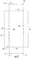
- FIG. 2is a plan view of a divider blank for forming a divider in the carton of FIG. 1 .
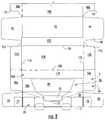
- FIG. 3is a plan view of the divider blank of FIG. 2 positioned on the carton blank of FIG. 1 .
- FIGS. 4A and 4Bshow the folding of the divider blank and the carton blank of FIG. 3 to form an open-ended sleeve.
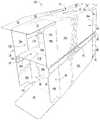
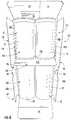
- FIG. 5Ais an exterior perspective view of the open-ended sleeve formed from the carton blank of FIG. 1 and the divider blank of FIG. 2 .
- FIG. 5Bis an interior perspective view of the open-ended sleeve of FIG. 5A .
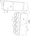
- FIG. 6is a perspective end view of the open-ended sleeve of FIGS. 5A and 5B loaded with containers.
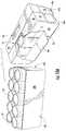
- FIGS. 7A and 7Bare perspective views of the erected carton according to the first exemplary embodiment of the disclosure.
- FIG. 8is a perspective view of the carton of FIGS. 7A and 7B with an actuated separating feature.
- FIGS. 9A and 9Bare perspective views of the carton of FIG. 8 separated into two sections 101 , 103 according to the first exemplary embodiment of the disclosure.
- FIGS. 10A and 10Bare perspective views of the separated of FIGS. 9A and 9B with an actuated dispenser.
- FIG. 11is an exterior plan view of a carton blank used to form a carton according to a second exemplary embodiment of the disclosure.
- FIG. 12is a plan view of a divider blank for forming a divider according to the second exemplary embodiment of the disclosure.
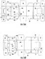
- FIG. 13is a plan view of the divider blank of FIG. 12 positioned on the carton blank of FIG. 11 .
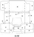
- FIG. 14is an exterior plan view of a carton blank used to form a carton according to a third exemplary embodiment of the disclosure.
- FIG. 15is a plan view of a divider blank for forming a divider according to the third exemplary embodiment of the disclosure.
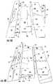
- FIG. 16A-16Care plan views of the divider blank of FIG. 15 positioned on the carton blank of FIG. 14 and showing the folding of the carton blank and the divider blank to form an open-ended sleeve.
- the present disclosuregenerally relates to cartons that contain articles such as containers, bottles, cans, etc.
- the articlescan be beverage containers used for packaging beverage products, for example.
- the articlescan be made from materials suitable in composition for packaging the particular food or beverage item, and the materials include, but are not limited to, aluminum and/or other metals; glass; plastics such as PET, LDPE, LLDPE, HDPE, PP, PS, PVC, EVOH, and Nylon; and the like, or any combination thereof.
- Cartons according to the present disclosurecan accommodate articles of any shape.
- beverage containerse.g., aluminum beverage cans
- the present disclosuregenerally relates to cartons housing a plurality of articles and a divider positioned between layers of articles.
- the articles in each layercan be of the same size and shape or the articles in each layer can be a different size and shape without departing from the disclosure.
- the terms “inner,” “outer,” “lower,” “bottom,” “upper,” and “top”indicate orientations determined in relation to fully erected and upright cartons.
- FIG. 1is a plan view of the exterior side 2 of a blank, generally indicated at 4 , used to form a carton 6 ( FIGS. 7A and 7B ) according to one embodiment of the disclosure.
- the carton 6can be used to house a plurality of articles such as containers C 1 , C 2 ( FIG. 6 ) arranged in two layers or tiers T 1 , T 2 , with the top layer T 1 including containers C 1 and the bottom layer T 2 including containers C 2 .
- the containers C 1 , C 2are different from one another (e.g., the containers C 1 could be 7.5 ounce cans and the containers C 2 could be 10.5 ounce cans, wherein, in one embodiment, the containers C 2 can be generally taller than the containers C 1 and the containers C 1 , C 2 can have a generally similar or identical diameter). Alternatively, the containers C 1 , C 2 could be similar or identical to one another.
- the carton 6is sized to house twenty containers C 1 , C 2 in a 2 ⁇ 5 ⁇ 2 arrangement, but it is understood that the carton 6 may be sized and shaped to hold containers C of a different or same quantity in more than two layers and/or in different row/column arrangements (e.g., 1 ⁇ 6 ⁇ 2, 3 ⁇ 6 ⁇ 2, 2 ⁇ 6 ⁇ 2, 3 ⁇ 5 ⁇ 2, 3 ⁇ 4 ⁇ 2, 4 ⁇ 5 ⁇ 2, etc.).
- the containers C 1 , C 2could be otherwise shaped, arranged, and/or configured without departing from the disclosure.
- the containers C 1 , C 2could be beverage bottles or other containers.
- the carton 6includes a handle, generally indicated at 12 ( FIGS. 7A-8 and 9B-10B ), for grasping and carrying the carton.
- the blank 4has a longitudinal axis L 1 and a lateral axis L 2 .
- the blank 4comprises a bottom panel 16 foldably connected to a first side panel 18 at a first lateral fold line 20 , a first top panel 24 foldably connected to the first side panel 18 at a second lateral fold line 26 , a second side panel 28 foldably connected to the bottom panel 16 at a third lateral fold line 30 , and a second top panel 36 foldably connected to the second side panel 28 at a fourth lateral fold line 38 .
- Any of the top panels 24 , 36 , the bottom panel 16 , and the side panels 18 , 28could be omitted or could be otherwise shaped, arranged, and/or configured without departing from the disclosure.
- the bottom panel 16is foldably connected to a first bottom end flap 44 and a second bottom end flap 46 .
- the first side panel 18is foldably connected to a first side end flap 48 and a second side end flap 50 .
- the first top panel 24is foldably connected to a first top end flap 52 and a second top end flap 54 .
- the second side panel 28is foldably connected to a first side end flap 56 and a second side end flap 58 .
- the second top panel 36is foldably connected to a third top end flap 62 and a fourth top end flap 64 .
- the end flaps 44 , 48 , 52 , 56 , 62close a first end 67 of the carton, and the end flaps 46 , 50 , 54 , 58 , 64 close a second end 69 of the carton.
- different flap arrangementscan be used for closing the ends of the carton 6 .
- the end flaps 44 , 48 , 52 , 56 , 62extend along a first marginal area of the blank 4 , and are foldably connected at a first longitudinal fold line 72 that extends along the length of the blank.
- the end flaps 46 , 50 , 54 , 58 , 64extend along a second marginal area of the blank 4 , and are foldably connected at a second longitudinal fold line 74 that also extends along the length of the blank.
- the longitudinal fold lines 72 , 74may be, for example, substantially straight, or offset at one or more locations to account for blank thickness or for other factors.
- the blank 4includes handle features for forming the handle 12 of the carton 6 .
- the handle featuresinclude a first opening 25 in the first top panel 24 and a second opening 35 in the second top panel 36 .
- the handle featuresmay include oblique fold lines 27 , 37 extending from a respective opening 25 , 35 to the fold lines 72 , 74 at respective corners of the top panels 24 , 36 to allow the first and second top panels to flex when the carton 6 is grasped and carried by the handle 12 .
- the handle featuresinclude a handle reinforcement panel 70 foldably connected to the second top panel 36 at a lateral fold line 71 . As shown in FIG.
- the handle reinforcement panel 70has a cutout 75 at a laterally extending edge 73 of the blank 4 and two reinforcing end flaps 76 , 77 adjacent the respective top end flaps 62 , 64 .
- the cutout 75can be generally aligned with the handle openings 25 , 35 along a longitudinal centerline of the blank 4 .
- the reinforcing end flaps 76 , 77can be foldably connected to the reinforcement panel 70 along respective fold lines or fold areas 78 , 79 .
- the handle 12 and/or the handle reinforcement panel 70could be omitted, could have other features, or could be otherwise shaped, arranged, and/or configured without departing from the disclosure.
- the blank 4may include dispensing or opening features for forming a first dispenser 81 adjacent the first handle opening 25 and a second dispenser 83 adjacent the second handle opening 35 .
- the first dispenser 81includes a first dispenser panel 85 formed by two dispenser tear lines 87 extending from the first handle opening 25 in the first top panel 24 and the first side panel 18 .
- the second dispenserincludes a second dispenser panel 89 formed by two dispenser tear lines 91 extending from the second handle opening 35 in the second top panel 36 and the second side panel 28 .
- the dispenser panels 85 , 89are foldably connected to the respective side panels 18 , 28 along respective fold line 86 , 88 .
- the dispensers 81 , 83could be omitted or could be otherwise shaped, arranged, and/or configured, without departing from the disclosure.
- the fold lines 86 , 88could be tear lines.
- the blank 4includes separating features that comprise a first tear strip 93 extending across the blank 4 in the lateral direction L 2 through the end flap 48 , the first side panel 18 , and the end flap 50 .
- the separating featurescan comprise a second tear strip 95 extending across the blank 4 in the lateral direction L 2 thorough the end flap 56 , the second side panel 28 , and the end flap 58 .
- each of the tear strips 93 , 95may comprise a pull tab 97 for grasping and removing the respective tear strip.
- the tear strips 93 , 95extend laterally across the entire width of the blank 4 between opposite peripheral edges of the blank. As shown in FIG.
- each of the tear strips 93 , 95is defined by two spaced tear lines configured for tearing in opposite directions.
- the tear stripscould be configured for tearing in the same direction.
- the first tear strip 93can extend between a first upper portion 18 a and a first lower portion 18 b of the first side panel 18 , between an upper end portion 48 a and a lower end portion 48 b of the first side end flap 48 , and between an upper end portion 50 a and a lower end portion 50 b of the second side end flap 50 .
- the second tear strip 95can extend between a second upper portion 28 a and a second lower portion 28 b of the second side panel 28 , between an upper end portion 56 a and a lower end portion 56 b of the first side end flap 56 , and between an upper end portion 58 a and a lower end portion 58 b of the second side end flap 58 .
- the tear strips 93 , 95divide the carton into a first (upper) modular section 101 and a second (lower) modular section 103 . Either of the tear strips 93 , 95 could be omitted or could be otherwise shaped, arranged, and/or configured without departing from the disclosure.
- the separating features for separating the first portion 101 and the second portion 103could be other weakening features (e.g., cuts, tear lines, etc.) that are alternative to tear strips and still allow separation of the first portion and the second portion of the carton 6 .
- FIG. 2is a plan view of the exterior side of a divider blank, generally indicated at 104 , used to form a divider 106 ( FIGS. 5A-6 and 9A ) in the carton 6 according to one embodiment of the disclosure.
- the divider blank 104comprises a central or divider panel 108 foldably connected to a first divider end flap 110 at a first lateral fold line 112 and a second divider end flap 114 at a second lateral fold line 116 .
- the divider blank 104can also include a first side attachment flap 118 foldably connected to the central panel 108 at a first longitudinal fold line 120 and a second side attachment flap 122 foldably connected to the central panel 108 at a second longitudinal fold line 124 .
- the divider blank 104could have other features or could be otherwise shaped, arranged, and/or configured without departing from the disclosure.
- any of the attachment flaps 118 , 122 and the divider end flaps 110 , 114could be omitted.
- the carton blank 4 and divider blank 104can be erected into the carton 6 as generally shown in FIGS. 3-6 .
- the carton blank 4is positioned with its interior side facing upward and the divider blank 104 is positioned as shown in FIG. 3 to overlap the carton blank 4 .
- locating features or corners 115 of the divider end flaps 110 , 114 of the divider blank 104are aligned with respective locating features or corners 15 of the end flaps 56 , 58 to properly position the attachment side flap 122 on the upper portion 28 a of the side panel 28 ( FIGS. 3 and 4A ).
- the corners 115 of the divider end flaps 110 , 114can be similar or identical in shape to at least a portion of each of the corners 15 of the lower portions 48 b , 50 b , 56 b , 58 b of the respective side end flaps 48 , 50 , 56 , 58 .
- each of the corners 15 , 115can include a lateral edge, a longitudinal edge, and an oblique edge of the respective end flap so that when the respective edges are aligned (e.g., when the edges of a corner 115 of the divider end flap 110 are aligned with the edges of a corner 15 of the lower portion 56 b and the edges of a corner 115 of the divider end flap 114 are aligned with the edges of a corner 15 of the lower portion 58 b ), such as by moving the edges against one or more guide plates (not shown), the divider can be positioned on the carton blank 104 so that the attachment side flap 118 can be adhered to the upper portion 28 a of the side panel 28 .
- the first side attachment flap 118can be positioned into face-to-face contact with the second side panel 28 of the carton blank 4 and adhered thereto by glue or other adhesive. In the illustrated embodiment, the first side attachment flap 118 can be adhered to the upper portion 28 a of the second side panel 28 and the central panel 108 can overlap the tear strip 95 and the lower portion 28 b of the second side panel 28 .
- the handle reinforcement panel 70is folded along the fold line 73 into face-to-face contact with the interior surface of the second top panel 36 so that the handle cutout 75 is generally aligned with the handle opening 35 and the reinforcement end flaps 76 , 77 overlap the respective top end flaps 62 , 64 .
- the handle reinforcement panel 70can be folded before or after positioning the divider blank 104 on the carton blank 4 and/or before or after adhering the first side attachment flap 118 to the upper portion 28 a of the second side panel 28 .
- the second top panel 36 of the carton blank 4can be folded along fold line 38 to at least partially overlap the upper portion 28 a of the second side panel 28 and the first side attachment flap 118 of the divider blank 104 .
- the second side attachment flap 122can be folded along fold line 124 to be in face-to-face contact with the divider panel 108 .
- the second top panel 36 and the second side attachment flap 122could be folded in any order or simultaneously.
- the first side panel 18can be folded along the fold line 20 so that the first top panel 24 overlaps at least a portion of the exterior side of the second top panel 36 .
- the first top panel 24can be glued to the overlapped portion of the second top panel 36 and the end flaps 52 , 54 can be glued to the overlapped portions of the end flaps 62 , 64 .
- the second side attachment flap 122 of the divider blank 104 and upper portion 18 a of the first side panel 18can be positioned into face-to-face contact and adhered by glue or other adhesive.
- the divider blank 104is attached to the carton blank 4 in the collapsed position shown in FIG. 4B by way of the adhesive attachment of the first side attachment flap 118 to the upper portion 28 a of the second side panel 28 and the adhesive attachment of the second side attachment flap 122 to the upper portion 18 a of the first side panel 18 .
- the attached carton blank 4 and divider blank 104then can be folded along fold lines 20 , 26 , 30 , 38 to form an open-ended sleeve 131 and divider 106 disposed therein ( FIGS. 5A-6 ).
- the divider 106can divide the interior of the sleeve into an upper space 133 and lower space 135 . As shown in FIG.
- the containers C 1 , C 2can be loaded into the interior of the open-ended sleeve 131 with the upper layer T 1 of containers C 1 being arranged in the upper space 133 of the interior and supported on the central panel 108 of the divider 106 and with the lower layer T 2 of containers C 2 being arranged in lower space 135 of the interior and supported on the bottom panel 16 .
- the attached carton blank 4 and divider blank 104may be otherwise formed into the open-ended sleeve 131 and divider 106 using alternative folding and gluing steps without departing from the scope of this disclosure.
- the ends 67 , 69 of the carton 5can be closed by at least partially overlapping and adhering the end flaps 44 , 48 , 52 , 56 , 62 , 76 at the first end 67 of the carton and at least partially overlapping and adhering the end flaps 46 , 50 , 54 , 58 , 64 , 77 at the second end 69 of the carton.
- the overlapped top end flaps at each ende.g., 52 , 62 at end 67
- the bottom end flap(e.g., 44 ) can be upwardly folded and secured to the side end flaps (e.g., 48 , 56 ) at the same end.
- the side end flaps 48 , 56 at the first end 67can be slightly spaced apart ( FIG. 7B ) and the side end flaps 50 , 58 at the second end 69 can be slightly spaced apart so that a respective opening is formed adjacent the ends of the tear strips 93 , 95 , which opening can make it easier to grasp the respective pull tab 97 at each end for initiating tearing of the respective tear strips 93 , 95 .
- the ends 67 , 69 of the carton 5could be closed by other closing steps and features without departing from the disclosure.
- the side end flapscould at least partially overlap one another at the closed ends and/or the tear strips 93 , 95 could at least partially overlap one another at one or both ends to form a substantially continuous tear strip.
- the carton 5can be alternatively loaded, such as by loading the containers after closing either of the ends 67 , 69 .
- the erected carton 6is shown in FIGS. 7A and 7B .
- the carton 6includes the first modular section 101 and the second modular section 103 connected by the tear strips 93 , 95 .
- the first modular sectionincludes the first upper portion 18 a of the first side panel 18 , the first top panel 24 , the second top panel 36 , the reinforcement panel 70 , the second upper portion 28 a of the second side panel 28 , the upper portions 48 a , 50 a of the respective side end flaps 48 , 50 , the upper portions 56 a , 58 a of the respective side end flaps 56 , 58 , the top end flaps 62 , 64 , the reinforcement end flaps 76 , 77 , and the divider 106 .
- the second modular section 103can include the bottom panel 16 , the first lower portion 18 b of the first side panel 18 , the second lower portion 28 b of the second side panel 28 , the bottom end flaps 44 , 46 , the lower portions 48 b , 50 b of the respective side end flaps 48 , 50 , and the lower portions 56 b , 58 b of the respective side end flaps 56 , 58 .
- the side attachment flaps 118 , 122 of the divider 106are attached to the upper portions 18 a , 28 a of the respective side panels 18 , 28 above the respective tear strips 93 , 95 .
- the divider end flaps 110 , 114are overlapped by and/or adhered to the respective upper portions 48 a , 56 a and 50 a , 58 a of the respective side end flaps 48 , 56 , 50 , 58 above the tear strips 93 , 95 so that the divider 106 is disposed in the first modular section 101 above the second modular section 103 and above the containers C 2 in the second layer T 2 .
- the first and second modular sections 101 , 103could be otherwise shaped, arranged, and/or configured without departing from the disclosure.
- the tear strips 93 , 95can be actuated to separate the first modular section 101 and the second modular section 103 of the carton 6 .
- the first modular section 101can be lifted and carried at the handle 12 (e.g., FIG. 10B ) to carry the top layer T 1 of containers C 1 .
- the tear strips 93 , 95are located below the divider 106 so that the first modular section 101 forms an enclosed container, which is at least partially enclosed by the top panels 25 , 36 , the reinforcement panel 70 , the upper portions 18 a , 28 a of the side panels 18 , 28 , a first upper closed end 67 a at least partially formed by the upper portions 48 a , 56 a of the side end flaps 48 , 56 , the top end flap 62 , and the top reinforcing flap 76 , and a second upper closed end 69 a at least partially formed by the upper portions 50 a , 56 a of the side panels 50 , 56 , the top end flap 64 , and the reinforcement end flap 77 .
- the central panel 108 of the divider 106can form a bottom of the first modular section 101 , supporting the containers C 1 within the first modular section.
- the second modular section 103 of the carton 6comprises a tray that has an open top that provides access to the bottom layer T 2 of containers C 2 supported on the bottom panel 16 .
- the tray of the second modular section 103can be partially enclosed by the bottom panel 16 , the lower portions 18 b , 28 b of the side panels 18 , 28 , a lower closed end 67 b at least partially formed by the bottom end flap 44 and the lower portions 48 b , 56 b of the side end flaps 48 , 56 , and a second lower closed end 69 b at least partially formed by the bottom end flap 46 and the lower portions 50 b , 58 b of the side end flaps 50 , 58 .
- the carton 6is a modular carton that allows the containers C 1 in the first modular section 101 to be separated and carried away from the containers C 2 in the second marginal section 103 .
- the carton 6could be separated in an alternative manner by other features without departing from the disclosure.
- one or both of the dispensers 81 , 83can be used to access the containers C 1 in the first modular section 101 by tearing along respective tear lines 87 , 91 to at least partially separate a respective dispenser panel 85 , 89 from the first modular section.
- the first modular section 101can be carried by grasping the handle 12 before or after ( FIG. 10B ) the dispenser(s) are actuated.
- the carton 6can be carried at the handle 12 prior to separating the modular sections from one another.
- one or both of the dispensers 81 , 83could be actuated to access the containers C 1 in the upper layer T 1 before the modular sections are separated.
- the handle 12 and/or the dispensers 81 , 83could be otherwise actuated without departing from the disclosure.
- the modular carton 6 with the separable first modular section 101 and second modular section 103can be suitable for use with containers C 1 in the upper modular section that contain a different product than the containers C 2 in the lower modular section.
- the containers C 1 , C 2 in the upper and lower modular sections 101 , 103can be different sized containers that contain a different volume of beverage or other product.
- containers C 2 in the second modular section 103are sized to contain 10.5 ounces of beverage
- the containers C 1 in the first modular section 101are sized to contain 7.5 ounces of beverage, with the containers C 1 , C 2 having a similar or identical diameter, but the containers C 2 being taller to accommodate higher volume of beverage.
- the containers C 1 , C 2could be otherwise shaped, configured, and/or arranged, such that the containers C 1 , C 2 are the same size, or the containers C 1 , C 2 are different size (e.g., in height and/or in diameter) without departing from the disclosure.
- FIGS. 11-13show a carton blank 204 and a divider blank 304 for forming a carton (not shown) according to a second embodiment of the disclosure.
- the second embodimentis generally similar to the first embodiment, except for variations noted and variations that will be apparent to one of ordinary skill in the art. Accordingly, similar or identical features of the embodiments have been given like or similar reference numbers.
- the carton blank 204 and the divider blank 304are sized to accommodate a 3 ⁇ 5 ⁇ 2 configuration of containers C 1 , C 2 .
- the carton blank 204includes four locating features or notches 215 .
- the notches 215are defined along and between the bottom end flap 244 and the side end flap 248 , the bottom end flap 244 and the side end flap 256 , the bottom end flap 246 and the side end flap 250 , and the bottom end flap 246 and the side end flap 258 , respectively.
- Each of the notches 215can extend along the edges of the respective end flaps and can come to a point or vertex 217 adjacent the respective intersection of the fold lines 272 , 220 , 230 , 274 .
- the end flaps 310 , 314 of the divider blank 304each include four locating features or notches 315 to assist in aligning the divider blank 304 with the carton blank 204 during the assembly process.
- the divider blank 304includes four notches 315 ( FIG. 12 ) or the divider blank could include two notches 315 ( FIG. 13 ).
- the four notches 315can provide additional orientation options for alignment of the blanks.
- Each of the notches 315can include a vertex 317 and can be similarly shaped as the notches 215 of the carton blank 204 . As shown in FIG.
- the notches 315can be aligned with respective notches 215 (e.g., so that the vertexes 217 , 317 generally line up with one another).
- the first side attachment flap 318can be adhesively secured to the second side panel 228 of the carton blank 204 in a similar manner of the first embodiment.
- the assembly of the carton of the second embodimentwould then continue in a similar manner as noted above for the first embodiment to attach the second side attachment flap 322 to the first side panel 218 of the carton blank 204 .
- the carton blank 204 of the second embodimentcould have other features and could be otherwise shaped, arranged, and/or configured without departing from the disclosure.
- the divider blank 304could have other features or could be otherwise shaped, arranged, and/or configured without departing from the disclosure.
- FIGS. 14 and 15show carton blank 404 and an insert blank 504 for forming a carton (not shown) according to a third embodiment of the disclosure.
- the third embodimentis generally similar to the previous embodiments, except for variations noted and variations that will be apparent to one of ordinary skill in the art. Accordingly, similar or identical features of the embodiments have been given like or similar reference numbers.
- the carton blank 404 and the divider blank 504are sized to accommodate a 2 ⁇ 3 ⁇ 2 configuration of containers C 1 , C 2 . As shown in FIG.
- the divider blank 504comprises a central panel 508 , divider end flaps 510 , 514 foldably connected to the central panel 508 along respective fold lines 512 , 516 , and side attachment flaps 518 , 522 foldably connected to the central panel 508 along respective fold lines 520 , 524 .
- the divider blank 504includes an extension flap 519 extending from the side attachment flap 518 and at least partially defined by a cut 521 in the divider panel 508 .
- the extension flap 519can be foldably connected to the side attachment flap 518 at the fold line 520 .
- the divider blank 504could have other features or could be otherwise shaped, arranged, and/or configured without departing from the disclosure.
- the extension flap 519could extend from the side attachment flap 518 without the fold line 520 (e.g., the cut line 521 and the extension flap 519 could interrupt the fold line 520 ).
- the modular carton of the third embodimentcan be assembled in a similar manner as the carton 6 of the first embodiment.
- the carton blank 404 and the divider blank 504can be at least partially overlapped with the divider end flaps 510 , 514 being aligned with the side end flaps 56 , 58 similarly to the assembly of the blanks 4 , 104 of the first embodiment (e.g., FIG. 3 ).
- the second side attachment flap 522can be adhered in face-to-face contact with the upper portion of the second side panel 28 of the carton blank 404 .
- the first side attachment flap 518can remain free from connection to the second side panel 28 .
- Glue or other adhesivecan be applied to the glue flap 519 before or after the initial attachment of the divider blank 504 to the carton blank 404 .
- the second top panel 36 and the reinforcement panel 70are folded over the side panel 28 similarly to the first embodiment.
- the first top panel 24 and the first side panel 18and are folded over the bottom panel 16 , the second side panel 18 , and the divider blank 504 to the position shown in FIG. 16C . Accordingly, the first side panel 18 is in face-to-face contact with the extension flap 519 and the side attachment flap 518 and the extension flap can be attached the divider blank 504 to the first side panel 18 by the adhesive.
- the side attachment flaps 518 , 522 and the extension flap 519can fold with respect to the central panel 508 so that the side panels 18 , 28 , the side attachment flaps 518 , 522 , and the extension flap 519 are generally vertical and the central panel 508 is generally horizontal in the open ended sleeve and the carton. Accordingly, the divider formed by the divider blank 504 is attached to the second side panel 28 by way of the second attachment flap 522 and is attached to the first side panel 18 by way of the extension flap 519 .
- the central panel 508then spans between the two side panels 18 , 28 in the erected carton in a similar manner as the carton 6 of the first embodiment.
- the extension flap 519folds with the side attachment flap 518 with respect to the central panel 508 , the extension flap 519 can separate from the central panel along the cut line 521 to form an opening extending in the central panel 508 adjacent the extension flap and the side attachment flap.
- an advantage of the third embodimentis that the step of folding the side attachment flap 118 (e.g., as shown in FIG. 4A ) can be omitted since the first side panel 18 can be glued to the extension flap 519 .
- the carton of the third embodimentcan be loaded in a similar manner as the carton of the first embodiment without departing from the disclosure.
- the blankmay be constructed from paperboard having a caliper so that it is heavier and more rigid than ordinary paper.
- the blankcan also be constructed of other materials, such as cardboard, or any other material having properties suitable for enabling the carton to function at least generally as described above.
- the blankcan be coated with, for example, a clay coating.
- the clay coatingmay then be printed over with product, advertising, and other information or images.
- the blankmay then be coated with a varnish to protect information printed on the blanks.
- the blankmay also be coated with, for example, a moisture barrier layer, on either or both sides of the blanks.
- the blankcan also be laminated to or coated with one or more sheet-like materials at selected panels or panel sections.
- a tear linecan include: a slit that extends partially into the material along the desired line of weakness, and/or a series of spaced apart slits that extend partially into and/or completely through the material along the desired line of weakness, or various combinations of these features.
- one type tear lineis in the form of a series of spaced apart slits that extend completely through the material, with adjacent slits being spaced apart slightly so that a nick (e.g., a small somewhat bridging-like piece of the material) is defined between the adjacent slits for typically temporarily connecting the material across the tear line. The nicks are broken during tearing along the tear line.
- the nickstypically are a relatively small percentage of the tear line, and alternatively the nicks can be omitted from or torn in a tear line such that the tear line is a continuous cut line. That is, it is within the scope of the present disclosure for each of the tear lines to be replaced with a continuous slit, or the like.
- a cut linecan be a continuous slit or could be wider than a slit without departing from the present disclosure.
- a fold linecan be any substantially linear, although not necessarily straight, form of weakening that facilitates folding there along. More specifically, but not for the purpose of narrowing the scope of the present disclosure, fold lines include: a score line, such as lines formed with a blunt scoring knife, or the like, which creates a crushed or depressed portion in the material along the desired line of weakness; a cut that extends partially into a material along the desired line of weakness, and/or a series of cuts that extend partially into and/or completely through the material along the desired line of weakness; and various combinations of these features. In situations where cutting is used to create a fold line, typically the cutting will not be overly extensive in a manner that might cause a reasonable user to incorrectly consider the fold line to be a tear line.
- the above embodimentsmay be described as having one or more panels adhered together by glue during erection of the carton embodiments.
- glueis intended to encompass all manner of adhesives commonly used to secure carton panels in place.
Landscapes
- Engineering & Computer Science (AREA)
- Mechanical Engineering (AREA)
- Cartons (AREA)
Abstract
Description
Claims (20)
Priority Applications (1)
| Application Number | Priority Date | Filing Date | Title |
|---|---|---|---|
| US15/992,607US10501226B2 (en) | 2015-07-29 | 2018-05-30 | Modular carton |
Applications Claiming Priority (4)
| Application Number | Priority Date | Filing Date | Title |
|---|---|---|---|
| US201562282271P | 2015-07-29 | 2015-07-29 | |
| US201562282661P | 2015-08-07 | 2015-08-07 | |
| US15/222,149US10017293B2 (en) | 2015-07-29 | 2016-07-28 | Modular carton |
| US15/992,607US10501226B2 (en) | 2015-07-29 | 2018-05-30 | Modular carton |
Related Parent Applications (1)
| Application Number | Title | Priority Date | Filing Date |
|---|---|---|---|
| US15/222,149ContinuationUS10017293B2 (en) | 2015-07-29 | 2016-07-28 | Modular carton |
Publications (2)
| Publication Number | Publication Date |
|---|---|
| US20180273237A1 US20180273237A1 (en) | 2018-09-27 |
| US10501226B2true US10501226B2 (en) | 2019-12-10 |
Family
ID=57885080
Family Applications (2)
| Application Number | Title | Priority Date | Filing Date |
|---|---|---|---|
| US15/222,149ActiveUS10017293B2 (en) | 2015-07-29 | 2016-07-28 | Modular carton |
| US15/992,607ActiveUS10501226B2 (en) | 2015-07-29 | 2018-05-30 | Modular carton |
Family Applications Before (1)
| Application Number | Title | Priority Date | Filing Date |
|---|---|---|---|
| US15/222,149ActiveUS10017293B2 (en) | 2015-07-29 | 2016-07-28 | Modular carton |
Country Status (4)
| Country | Link |
|---|---|
| US (2) | US10017293B2 (en) |
| AU (1) | AU2016298258C1 (en) |
| CA (1) | CA2990462C (en) |
| WO (1) | WO2017019853A1 (en) |
Cited By (2)
| Publication number | Priority date | Publication date | Assignee | Title |
|---|---|---|---|---|
| US11254465B2 (en) | 2019-07-18 | 2022-02-22 | Graphic Packaging International, Llc | Carton with attachment features |
| US11472597B1 (en)* | 2019-09-24 | 2022-10-18 | Packaging Corporation Of America | Separable multi-compartment container |
Families Citing this family (3)
| Publication number | Priority date | Publication date | Assignee | Title |
|---|---|---|---|---|
| CA2990462C (en)* | 2015-07-29 | 2020-08-04 | Graphic Packaging International, Inc. | Modular carton |
| US20180327135A1 (en)* | 2015-11-17 | 2018-11-15 | The Coca-Cola Company | Cartons with separable sections |
| BE1026374B1 (en)* | 2018-06-15 | 2020-01-22 | Anheuser Busch Inbev Sa | Portable cooling multipack |
Citations (112)
| Publication number | Priority date | Publication date | Assignee | Title |
|---|---|---|---|---|
| US1120752A (en) | 1913-12-12 | 1914-12-15 | Cassius C Smiley | Egg-carton. |
| US1896326A (en) | 1929-09-28 | 1933-02-07 | Robinson E S & A Ltd | Container or box for fragile articles |
| US1898646A (en) | 1929-12-10 | 1933-02-21 | Richardson Taylor Globe Corp | Display box |
| GB434145A (en) | 1933-05-06 | 1935-08-27 | Charles Augustus Fox | Improvements in or relating to cartons |
| US2111376A (en) | 1937-09-20 | 1938-03-15 | American Box Board Co | Box structure |
| US2151472A (en) | 1937-05-12 | 1939-03-21 | Wabash Fibre Box Company | Carton |
| US2312846A (en) | 1941-02-08 | 1943-03-02 | Gen Box Company | Shipping container for baby chicks and method of making same |
| US2475107A (en) | 1945-03-06 | 1949-07-05 | Kitchener K Newsom | Shipping box |
| CH263456A (en) | 1948-05-21 | 1949-08-31 | Cafag Cartonnagenfabrik Freibu | Ampoule pack. |
| US2758774A (en) | 1955-02-21 | 1956-08-14 | Marathon Corp | Package |
| US2844294A (en) | 1955-12-12 | 1958-07-22 | Old Dominion Box Company Inc | Chick carton |
| US2854050A (en) | 1957-02-11 | 1958-09-30 | James J Cannon | Collapsible hat box |
| US2875942A (en) | 1956-09-05 | 1959-03-03 | Owens Illinois Glass Co | Corner construction for boxes |
| US3006523A (en) | 1958-12-31 | 1961-10-31 | Mead Corp | Shipping case |
| US3101880A (en) | 1960-07-18 | 1963-08-27 | Longview Fibre Co | Divisible case |
| US3158312A (en) | 1961-12-05 | 1964-11-24 | Continental Can Co | Folded carton having separable units |
| FR1427897A (en) | 1964-12-29 | 1966-02-11 | Tailleur Ets | Cardboard display packaging for fruits |
| FR1489087A (en) | 1966-05-05 | 1967-07-21 | Cartonneries De Lumbres Soc In | Packaging for the transport and presentation of fruits such as pineapples |
| FR1497652A (en) | 1966-09-02 | 1967-10-13 | Rochette Cenpa | Wedging device for centering wrapped objects |
| US3664494A (en) | 1969-11-21 | 1972-05-23 | Reynolds Guyer Inc | Shipping and display containers |
| US3732976A (en) | 1971-04-12 | 1973-05-15 | Packaging Corp America | Package for fragile articles |
| US3822785A (en) | 1972-10-13 | 1974-07-09 | Westinghouse Electric Corp | Sleeve container for lamp bulbs or the like, and resulting package |
| FR2223985A5 (en) | 1973-03-28 | 1974-10-25 | Beghin | Packaging for stemmed glassware - locates and holds the foot and has separators to avoid crushing the bodies |
| US3937326A (en) | 1973-07-18 | 1976-02-10 | Andre Schick | Product display carton |
| US4105154A (en) | 1977-04-05 | 1978-08-08 | American Can Company | Packaging structure and its fabrication |
| US4120443A (en) | 1978-02-06 | 1978-10-17 | Container Corporation Of America | Cushioning insert |
| US4138052A (en) | 1977-08-22 | 1979-02-06 | Torigian Puzant C | Multi-layer tray dispenser package |
| US4421229A (en) | 1981-06-29 | 1983-12-20 | Paxall, Inc. | Double tray case |
| US4530459A (en) | 1983-09-16 | 1985-07-23 | James River - Norwalk, Inc. | Folding carrier carton including split cover closure, removable trays and blanks for making same |
| US4577799A (en) | 1985-01-28 | 1986-03-25 | The Mead Corporation | Panel interlocking means |
| US4621766A (en) | 1985-06-28 | 1986-11-11 | Inland Container Corporation | Triple-end container and blank therefor |
| JPS6262617A (en) | 1985-09-13 | 1987-03-19 | Sankusu Kk | Control circuit |
| JPS62130024A (en) | 1985-11-30 | 1987-06-12 | Toshiba Corp | phase locked circuit |
| US4739921A (en) | 1987-04-13 | 1988-04-26 | Clifford Taub | Storage box with tray |
| GB2198709A (en) | 1986-12-06 | 1988-06-22 | Bonar Cooke Cartons Ltd | Carton-forming blank |
| DE8814144U1 (en) | 1988-11-11 | 1989-01-05 | Zewawell AG & Co KG PWA-Verpackungswerke, 68219 Mannheim | Cushion for a packaging container |
| US4811837A (en) | 1987-03-25 | 1989-03-14 | United Brands Company | Produce shipment and separable distribution and display carton |
| JPS6473121A (en) | 1987-09-14 | 1989-03-17 | Yanmar Diesel Engine Co | Intake device for v-row internal combustion engine |
| JPH0173121U (en) | 1987-07-28 | 1989-05-17 | ||
| FR2626256A1 (en) | 1988-01-22 | 1989-07-28 | Nicollet Hugues Sa | Packaging assembly, particularly for quantities of articles to be delivered in groups |
| US4913291A (en)* | 1988-12-29 | 1990-04-03 | Manville Corporation | Separable article carrier |
| US4919269A (en)* | 1988-11-18 | 1990-04-24 | The Mead Corporation | Multiple compartment container |
| US5076492A (en) | 1991-03-27 | 1991-12-31 | General Electric Company | Carton having integral, removable platform |
| DE9111941U1 (en) | 1991-09-20 | 1992-01-09 | Avon Cosmetics GmbH, 8056 Neufahrn | Cuboid-shaped shipping packaging made of foldable material |
| WO1992007772A1 (en) | 1990-10-30 | 1992-05-14 | Riverwood International Corporation | Article carrier with side handles |
| JPH057621A (en) | 1991-07-03 | 1993-01-19 | Sugiyamagorou Shoten:Kk | Hand pump device for extracorporeal circulation |
| US5190211A (en) | 1992-04-27 | 1993-03-02 | The Mead Corporation | Snack display |
| US5234102A (en) | 1992-02-11 | 1993-08-10 | Riverwood International Corporation | Carrier for stacked articles |
| US5246113A (en) | 1992-02-11 | 1993-09-21 | Riverwood International Corporation | Carrier for stacked articles |
| US5299733A (en)* | 1990-04-17 | 1994-04-05 | Container Systems, Inc. | Detachable multi-unit package with flap |
| EP0595602A1 (en) | 1992-10-27 | 1994-05-04 | The Mead Corporation | Divider panel for two-tier can carton and carton incorporating such panel |
| US5316210A (en) | 1993-05-14 | 1994-05-31 | Georgia-Pacific Corporation | Paperboard storage container |
| JPH07125745A (en) | 1993-10-22 | 1995-05-16 | Suntory Ltd | Common intermediate partition for fancy box |
| US5415344A (en) | 1994-09-21 | 1995-05-16 | Riverwood International Corporation | Open-top container |
| US5427242A (en) | 1993-08-31 | 1995-06-27 | The Mead Corporation | Two tier can package having secured divider panel and method of forming the same |
| US5437143A (en) | 1993-09-20 | 1995-08-01 | The Mead Corporation | Method of forming a package of beverage cans |
| US5518111A (en) | 1994-03-02 | 1996-05-21 | The Mead Corporation | Removable divider panel for multiple-tier article package |
| US5538130A (en) | 1995-02-21 | 1996-07-23 | Riverwood International Corporation | Basket-style carrier with dividing strap |
| WO1996029261A1 (en) | 1994-03-02 | 1996-09-26 | The Mead Corporation | Removable divider panel for multiple-tier article package |
| US5620094A (en) | 1996-05-21 | 1997-04-15 | Riverwood International Corporation | Wrap-around carrier with top divider tab |
| JPH09142449A (en) | 1995-11-15 | 1997-06-03 | Rengo Co Ltd | Box with partition |
| US5669500A (en) | 1996-01-19 | 1997-09-23 | Riverwood International Corporation | Carrier for stacked bottles |
| US5682984A (en)* | 1995-01-19 | 1997-11-04 | The C.W. Zumbiel Co. | Two tier can carton |
| US5699957A (en) | 1993-04-21 | 1997-12-23 | The Mead Corporation | Multiple compartment separable container |
| US5772030A (en) | 1997-03-24 | 1998-06-30 | The Mead Corporation | Carton for packaging two tiers of articles |
| GB2323352A (en) | 1997-03-19 | 1998-09-23 | Procter & Gamble | Container |
| US5813540A (en) | 1994-11-10 | 1998-09-29 | Douglas Machine Limited Liability Company | Shrink film-encased double-tiered package |
| US5826783A (en) | 1997-06-09 | 1998-10-27 | The Mead Corporation | Two-tier can package having divider panel and method of forming the same |
| US5826870A (en) | 1994-02-04 | 1998-10-27 | Riverwood International Corporation | Divider sheet for stacked products and method of supplying planar articles |
| US5848686A (en) | 1997-10-31 | 1998-12-15 | Dean; Carl Andy | Collating structure |
| US5853088A (en) | 1994-12-02 | 1998-12-29 | The Mead Corporation | Carton |
| US5868252A (en) | 1997-05-15 | 1999-02-09 | The Mead Corporation | Divider panel with anchor panel window aperture |
| JPH11130049A (en) | 1997-10-30 | 1999-05-18 | Kao Corp | Packaging aid |
| WO1999028198A1 (en) | 1997-11-28 | 1999-06-10 | Riverwood International Corporation | Paperboard carton with end wall handles |
| US5938109A (en) | 1997-02-26 | 1999-08-17 | Sainz; Raymond | Carton and one-piece production blank therefor |
| US5957288A (en) | 1994-08-17 | 1999-09-28 | Riverwood International Corporation | Divider panel for stacked cans |
| US5967406A (en) | 1998-06-09 | 1999-10-19 | Georgia Pacific Corporation | Container convertible between shipping and shipping/display modes |
| US5996883A (en) | 1997-06-10 | 1999-12-07 | The Mead Corporation | Carton and a handle therefor |
| US6012630A (en) | 1997-10-23 | 2000-01-11 | Graphic Packaging Corporation | Container with multiple transverse dividers |
| JP2000085754A (en) | 1998-09-11 | 2000-03-28 | Fuji Seal Inc | Packaging case |
| WO2000020288A1 (en) | 1998-10-06 | 2000-04-13 | Riverwood International Corporation | Handled bottle carrier |
| JP2000238779A (en) | 1999-02-24 | 2000-09-05 | Kitahara Sangyo:Kk | Assembly type tiered boxes made of paper |
| US6112977A (en) | 1999-02-03 | 2000-09-05 | Riverwood International Corporation | Bottle carrier with dividers |
| US6176419B1 (en) | 2000-02-29 | 2001-01-23 | The Mead Corporation | Carton with article dispensing feature |
| WO2001030659A1 (en) | 1999-10-26 | 2001-05-03 | Unilever Plc | Divisible multi-carton package |
| US6244502B1 (en) | 1999-07-29 | 2001-06-12 | Weyerhaeuser Company | Self-dividing box, components thereof, and method of manufacturing, assembly and disassembling the same |
| WO2002030764A2 (en) | 2000-10-13 | 2002-04-18 | Meadwestvaco Packaging Systems, Llc | Carton and carton blanks |
| US6386369B2 (en) | 1999-08-12 | 2002-05-14 | Colgate Palmolive Company | Shipper and display carton |
| US6402020B1 (en) | 2001-01-08 | 2002-06-11 | Weyerhaeuser Company | Container with locking reinforcement panels |
| US20030080180A1 (en) | 2001-10-27 | 2003-05-01 | Holley John M. | Carton having a strap handle |
| WO2004014755A1 (en) | 2002-08-08 | 2004-02-19 | Graphic Packaging International, Inc | Dispensing package |
| US20040155098A1 (en) | 2003-02-12 | 2004-08-12 | Harrelson Glen R. | Dispensing system for double stack carton |
| US20040245327A1 (en) | 2003-06-06 | 2004-12-09 | Jimmy Oliff | Separable dual carton |
| US20050023331A1 (en) | 2003-07-30 | 2005-02-03 | Hirschey Urban C. | Two-tiered pastry box |
| US20050067477A1 (en) | 2003-09-30 | 2005-03-31 | Mcclure Jack A. | Stackable case ready breaker container and blank |
| US20050115843A1 (en)* | 2003-12-02 | 2005-06-02 | Harrelson Glen R. | Carton with an interlocking divider pad |
| US20050167292A1 (en) | 2004-01-30 | 2005-08-04 | Sutherland Robert L. | Beveled corner carton with an interlocking separator pad |
| US20050167290A1 (en) | 2004-01-30 | 2005-08-04 | Sutherland Robert L. | Fully enclosed pack with interlocking separator pad and dispenser |
| US6926193B2 (en) | 2001-01-13 | 2005-08-09 | Graphic Packaging International, Inc. | Paperboard carton with reinforced handle |
| US20050173269A1 (en) | 2002-06-26 | 2005-08-11 | Lebras Philippe | Carton and carton blank |
| US20050189406A1 (en) | 2004-02-26 | 2005-09-01 | Welchel Debra N. | Shipping carton with pull tabs and tear strip |
| US20060283926A1 (en) | 2005-06-16 | 2006-12-21 | Georgia-Pacific Corporation | Carton with a load-bearing divider shelf |
| US20070170232A1 (en) | 2006-01-25 | 2007-07-26 | Graphics Packaging International, Inc. | Side handles for a carton |
| US7270259B2 (en) | 2003-05-31 | 2007-09-18 | Graphic Packaging International, Inc. | Enclosed container carton convertible into a tray |
| US7717321B2 (en) | 2005-02-11 | 2010-05-18 | Graphic Packaging International, Inc. | Carton with interlocking divider |
| US7793821B2 (en) | 2006-09-12 | 2010-09-14 | Graphic Packaging International, Inc. | Carton with integrated tray |
| US7823721B2 (en) | 2007-10-18 | 2010-11-02 | Graphic Packaging International, Inc. | Package for containers |
| US20110132978A1 (en) | 2009-12-07 | 2011-06-09 | De Sousa Rogerio Luiz | Folding box |
| US8459535B2 (en) | 2007-06-29 | 2013-06-11 | Graphic Packaging International, Inc. | Carton with divider |
| US20130256392A1 (en) | 2012-03-29 | 2013-10-03 | Graphic Packaging International, Inc. | Carton with tray |
| US9415915B2 (en) | 2013-05-24 | 2016-08-16 | Graphic Packaging International, Inc. | Carton for articles |
| US10017293B2 (en)* | 2015-07-29 | 2018-07-10 | Graphic Packaging International, Llc | Modular carton |
- 2016
- 2016-07-28CACA2990462Apatent/CA2990462C/enactiveActive
- 2016-07-28USUS15/222,149patent/US10017293B2/enactiveActive
- 2016-07-28WOPCT/US2016/044448patent/WO2017019853A1/ennot_activeCeased
- 2016-07-28AUAU2016298258Apatent/AU2016298258C1/ennot_activeCeased
- 2018
- 2018-05-30USUS15/992,607patent/US10501226B2/enactiveActive
Patent Citations (127)
| Publication number | Priority date | Publication date | Assignee | Title |
|---|---|---|---|---|
| US1120752A (en) | 1913-12-12 | 1914-12-15 | Cassius C Smiley | Egg-carton. |
| US1896326A (en) | 1929-09-28 | 1933-02-07 | Robinson E S & A Ltd | Container or box for fragile articles |
| US1898646A (en) | 1929-12-10 | 1933-02-21 | Richardson Taylor Globe Corp | Display box |
| GB434145A (en) | 1933-05-06 | 1935-08-27 | Charles Augustus Fox | Improvements in or relating to cartons |
| US2151472A (en) | 1937-05-12 | 1939-03-21 | Wabash Fibre Box Company | Carton |
| US2111376A (en) | 1937-09-20 | 1938-03-15 | American Box Board Co | Box structure |
| US2312846A (en) | 1941-02-08 | 1943-03-02 | Gen Box Company | Shipping container for baby chicks and method of making same |
| US2475107A (en) | 1945-03-06 | 1949-07-05 | Kitchener K Newsom | Shipping box |
| CH263456A (en) | 1948-05-21 | 1949-08-31 | Cafag Cartonnagenfabrik Freibu | Ampoule pack. |
| US2758774A (en) | 1955-02-21 | 1956-08-14 | Marathon Corp | Package |
| US2844294A (en) | 1955-12-12 | 1958-07-22 | Old Dominion Box Company Inc | Chick carton |
| US2875942A (en) | 1956-09-05 | 1959-03-03 | Owens Illinois Glass Co | Corner construction for boxes |
| US2854050A (en) | 1957-02-11 | 1958-09-30 | James J Cannon | Collapsible hat box |
| US3006523A (en) | 1958-12-31 | 1961-10-31 | Mead Corp | Shipping case |
| US3101880A (en) | 1960-07-18 | 1963-08-27 | Longview Fibre Co | Divisible case |
| US3158312A (en) | 1961-12-05 | 1964-11-24 | Continental Can Co | Folded carton having separable units |
| FR1427897A (en) | 1964-12-29 | 1966-02-11 | Tailleur Ets | Cardboard display packaging for fruits |
| FR1489087A (en) | 1966-05-05 | 1967-07-21 | Cartonneries De Lumbres Soc In | Packaging for the transport and presentation of fruits such as pineapples |
| FR1497652A (en) | 1966-09-02 | 1967-10-13 | Rochette Cenpa | Wedging device for centering wrapped objects |
| US3664494A (en) | 1969-11-21 | 1972-05-23 | Reynolds Guyer Inc | Shipping and display containers |
| US3732976A (en) | 1971-04-12 | 1973-05-15 | Packaging Corp America | Package for fragile articles |
| US3822785A (en) | 1972-10-13 | 1974-07-09 | Westinghouse Electric Corp | Sleeve container for lamp bulbs or the like, and resulting package |
| FR2223985A5 (en) | 1973-03-28 | 1974-10-25 | Beghin | Packaging for stemmed glassware - locates and holds the foot and has separators to avoid crushing the bodies |
| US3937326A (en) | 1973-07-18 | 1976-02-10 | Andre Schick | Product display carton |
| US4105154A (en) | 1977-04-05 | 1978-08-08 | American Can Company | Packaging structure and its fabrication |
| US4138052A (en) | 1977-08-22 | 1979-02-06 | Torigian Puzant C | Multi-layer tray dispenser package |
| US4120443A (en) | 1978-02-06 | 1978-10-17 | Container Corporation Of America | Cushioning insert |
| US4421229A (en) | 1981-06-29 | 1983-12-20 | Paxall, Inc. | Double tray case |
| US4530459A (en) | 1983-09-16 | 1985-07-23 | James River - Norwalk, Inc. | Folding carrier carton including split cover closure, removable trays and blanks for making same |
| US4577799A (en) | 1985-01-28 | 1986-03-25 | The Mead Corporation | Panel interlocking means |
| US4621766A (en) | 1985-06-28 | 1986-11-11 | Inland Container Corporation | Triple-end container and blank therefor |
| JPS6262617A (en) | 1985-09-13 | 1987-03-19 | Sankusu Kk | Control circuit |
| JPS62130024A (en) | 1985-11-30 | 1987-06-12 | Toshiba Corp | phase locked circuit |
| GB2198709A (en) | 1986-12-06 | 1988-06-22 | Bonar Cooke Cartons Ltd | Carton-forming blank |
| US4811837A (en) | 1987-03-25 | 1989-03-14 | United Brands Company | Produce shipment and separable distribution and display carton |
| US4739921A (en) | 1987-04-13 | 1988-04-26 | Clifford Taub | Storage box with tray |
| JPH0173121U (en) | 1987-07-28 | 1989-05-17 | ||
| JPS6473121A (en) | 1987-09-14 | 1989-03-17 | Yanmar Diesel Engine Co | Intake device for v-row internal combustion engine |
| FR2626256A1 (en) | 1988-01-22 | 1989-07-28 | Nicollet Hugues Sa | Packaging assembly, particularly for quantities of articles to be delivered in groups |
| DE8814144U1 (en) | 1988-11-11 | 1989-01-05 | Zewawell AG & Co KG PWA-Verpackungswerke, 68219 Mannheim | Cushion for a packaging container |
| US4919269A (en)* | 1988-11-18 | 1990-04-24 | The Mead Corporation | Multiple compartment container |
| US4913291A (en)* | 1988-12-29 | 1990-04-03 | Manville Corporation | Separable article carrier |
| US5299733A (en)* | 1990-04-17 | 1994-04-05 | Container Systems, Inc. | Detachable multi-unit package with flap |
| WO1992007772A1 (en) | 1990-10-30 | 1992-05-14 | Riverwood International Corporation | Article carrier with side handles |
| US5076492A (en) | 1991-03-27 | 1991-12-31 | General Electric Company | Carton having integral, removable platform |
| JPH057621A (en) | 1991-07-03 | 1993-01-19 | Sugiyamagorou Shoten:Kk | Hand pump device for extracorporeal circulation |
| DE9111941U1 (en) | 1991-09-20 | 1992-01-09 | Avon Cosmetics GmbH, 8056 Neufahrn | Cuboid-shaped shipping packaging made of foldable material |
| US5234102A (en) | 1992-02-11 | 1993-08-10 | Riverwood International Corporation | Carrier for stacked articles |
| US5246113A (en) | 1992-02-11 | 1993-09-21 | Riverwood International Corporation | Carrier for stacked articles |
| US5190211A (en) | 1992-04-27 | 1993-03-02 | The Mead Corporation | Snack display |
| EP0595602A1 (en) | 1992-10-27 | 1994-05-04 | The Mead Corporation | Divider panel for two-tier can carton and carton incorporating such panel |
| US5699957A (en) | 1993-04-21 | 1997-12-23 | The Mead Corporation | Multiple compartment separable container |
| US5316210A (en) | 1993-05-14 | 1994-05-31 | Georgia-Pacific Corporation | Paperboard storage container |
| US5427242A (en) | 1993-08-31 | 1995-06-27 | The Mead Corporation | Two tier can package having secured divider panel and method of forming the same |
| US5437143A (en) | 1993-09-20 | 1995-08-01 | The Mead Corporation | Method of forming a package of beverage cans |
| JPH07125745A (en) | 1993-10-22 | 1995-05-16 | Suntory Ltd | Common intermediate partition for fancy box |
| US5826870A (en) | 1994-02-04 | 1998-10-27 | Riverwood International Corporation | Divider sheet for stacked products and method of supplying planar articles |
| US5518111A (en) | 1994-03-02 | 1996-05-21 | The Mead Corporation | Removable divider panel for multiple-tier article package |
| WO1996029261A1 (en) | 1994-03-02 | 1996-09-26 | The Mead Corporation | Removable divider panel for multiple-tier article package |
| US5957288A (en) | 1994-08-17 | 1999-09-28 | Riverwood International Corporation | Divider panel for stacked cans |
| US5415344A (en) | 1994-09-21 | 1995-05-16 | Riverwood International Corporation | Open-top container |
| US5813540A (en) | 1994-11-10 | 1998-09-29 | Douglas Machine Limited Liability Company | Shrink film-encased double-tiered package |
| US5853088A (en) | 1994-12-02 | 1998-12-29 | The Mead Corporation | Carton |
| US5682984A (en)* | 1995-01-19 | 1997-11-04 | The C.W. Zumbiel Co. | Two tier can carton |
| US5538130A (en) | 1995-02-21 | 1996-07-23 | Riverwood International Corporation | Basket-style carrier with dividing strap |
| JPH09142449A (en) | 1995-11-15 | 1997-06-03 | Rengo Co Ltd | Box with partition |
| US5669500A (en) | 1996-01-19 | 1997-09-23 | Riverwood International Corporation | Carrier for stacked bottles |
| US5620094A (en) | 1996-05-21 | 1997-04-15 | Riverwood International Corporation | Wrap-around carrier with top divider tab |
| US5938109A (en) | 1997-02-26 | 1999-08-17 | Sainz; Raymond | Carton and one-piece production blank therefor |
| GB2323352A (en) | 1997-03-19 | 1998-09-23 | Procter & Gamble | Container |
| US5772030A (en) | 1997-03-24 | 1998-06-30 | The Mead Corporation | Carton for packaging two tiers of articles |
| US5868252A (en) | 1997-05-15 | 1999-02-09 | The Mead Corporation | Divider panel with anchor panel window aperture |
| WO1998056684A1 (en) | 1997-06-09 | 1998-12-17 | The Mead Corporation | Two-tier can package having divider panel and method of forming the same |
| US5826783A (en) | 1997-06-09 | 1998-10-27 | The Mead Corporation | Two-tier can package having divider panel and method of forming the same |
| US5996883A (en) | 1997-06-10 | 1999-12-07 | The Mead Corporation | Carton and a handle therefor |
| US6012630A (en) | 1997-10-23 | 2000-01-11 | Graphic Packaging Corporation | Container with multiple transverse dividers |
| JPH11130049A (en) | 1997-10-30 | 1999-05-18 | Kao Corp | Packaging aid |
| US5848686A (en) | 1997-10-31 | 1998-12-15 | Dean; Carl Andy | Collating structure |
| US6250542B1 (en) | 1997-11-28 | 2001-06-26 | Riverwood International Corporation | Paperboard carton with end wall handles |
| WO1999028198A1 (en) | 1997-11-28 | 1999-06-10 | Riverwood International Corporation | Paperboard carton with end wall handles |
| US5967406A (en) | 1998-06-09 | 1999-10-19 | Georgia Pacific Corporation | Container convertible between shipping and shipping/display modes |
| JP2000085754A (en) | 1998-09-11 | 2000-03-28 | Fuji Seal Inc | Packaging case |
| WO2000020288A1 (en) | 1998-10-06 | 2000-04-13 | Riverwood International Corporation | Handled bottle carrier |
| US6065590A (en) | 1998-10-06 | 2000-05-23 | Riverwood International Corporation | Handled bottle carrier |
| JP2002526346A (en) | 1998-10-06 | 2002-08-20 | リバーウッド・インターナショナル・コーポレーション | Bottle carrier with handle |
| US6112977A (en) | 1999-02-03 | 2000-09-05 | Riverwood International Corporation | Bottle carrier with dividers |
| JP2000238779A (en) | 1999-02-24 | 2000-09-05 | Kitahara Sangyo:Kk | Assembly type tiered boxes made of paper |
| US6244502B1 (en) | 1999-07-29 | 2001-06-12 | Weyerhaeuser Company | Self-dividing box, components thereof, and method of manufacturing, assembly and disassembling the same |
| US6386369B2 (en) | 1999-08-12 | 2002-05-14 | Colgate Palmolive Company | Shipper and display carton |
| WO2001030659A1 (en) | 1999-10-26 | 2001-05-03 | Unilever Plc | Divisible multi-carton package |
| US6176419B1 (en) | 2000-02-29 | 2001-01-23 | The Mead Corporation | Carton with article dispensing feature |
| WO2002030764A2 (en) | 2000-10-13 | 2002-04-18 | Meadwestvaco Packaging Systems, Llc | Carton and carton blanks |
| US6402020B1 (en) | 2001-01-08 | 2002-06-11 | Weyerhaeuser Company | Container with locking reinforcement panels |
| US6926193B2 (en) | 2001-01-13 | 2005-08-09 | Graphic Packaging International, Inc. | Paperboard carton with reinforced handle |
| US20030080180A1 (en) | 2001-10-27 | 2003-05-01 | Holley John M. | Carton having a strap handle |
| US20050173269A1 (en) | 2002-06-26 | 2005-08-11 | Lebras Philippe | Carton and carton blank |
| WO2004014755A1 (en) | 2002-08-08 | 2004-02-19 | Graphic Packaging International, Inc | Dispensing package |
| US6991107B2 (en) | 2003-02-12 | 2006-01-31 | Graphic Packaging International, Inc. | Dispensing system for double stack carton |
| US6918487B2 (en) | 2003-02-12 | 2005-07-19 | Graphic Packaging International, Inc. | Dispensing system for double stack carton |
| US20040155098A1 (en) | 2003-02-12 | 2004-08-12 | Harrelson Glen R. | Dispensing system for double stack carton |
| US7270259B2 (en) | 2003-05-31 | 2007-09-18 | Graphic Packaging International, Inc. | Enclosed container carton convertible into a tray |
| US20040245327A1 (en) | 2003-06-06 | 2004-12-09 | Jimmy Oliff | Separable dual carton |
| US20050023331A1 (en) | 2003-07-30 | 2005-02-03 | Hirschey Urban C. | Two-tiered pastry box |
| US20050067477A1 (en) | 2003-09-30 | 2005-03-31 | Mcclure Jack A. | Stackable case ready breaker container and blank |
| US20050115843A1 (en)* | 2003-12-02 | 2005-06-02 | Harrelson Glen R. | Carton with an interlocking divider pad |
| US7168558B2 (en) | 2003-12-02 | 2007-01-30 | Graphic Packaging International, Inc. | Carton with an interlocking divider pad |
| US20050167290A1 (en) | 2004-01-30 | 2005-08-04 | Sutherland Robert L. | Fully enclosed pack with interlocking separator pad and dispenser |
| US7093713B2 (en) | 2004-01-30 | 2006-08-22 | Graphic Packaging International, Inc. | Fully enclosed pack with interlocking separator pad and dispenser |
| US7195118B2 (en) | 2004-01-30 | 2007-03-27 | Graphic Packaging International, Inc. | Beveled corner carton with an interlocking separator pad |
| US20050167292A1 (en) | 2004-01-30 | 2005-08-04 | Sutherland Robert L. | Beveled corner carton with an interlocking separator pad |
| US7475778B2 (en) | 2004-01-30 | 2009-01-13 | Graphic Packaging International, Inc. | Fully enclosed pack with interlocking separator pad and dispenser |
| US20050189406A1 (en) | 2004-02-26 | 2005-09-01 | Welchel Debra N. | Shipping carton with pull tabs and tear strip |
| US8127980B2 (en) | 2005-02-11 | 2012-03-06 | Graphic Packaging International, Inc. | Carton with interlocking divider |
| US7717321B2 (en) | 2005-02-11 | 2010-05-18 | Graphic Packaging International, Inc. | Carton with interlocking divider |
| US8628000B2 (en) | 2005-02-11 | 2014-01-14 | Graphic Packaging International, Inc. | Carton with interlocking divider |
| US20060283926A1 (en) | 2005-06-16 | 2006-12-21 | Georgia-Pacific Corporation | Carton with a load-bearing divider shelf |
| US7578427B2 (en) | 2005-06-16 | 2009-08-25 | Georgia-Pacific Corrugated Llc | Carton with a load-bearing divider shelf |
| US20070170232A1 (en) | 2006-01-25 | 2007-07-26 | Graphics Packaging International, Inc. | Side handles for a carton |
| US7832622B2 (en) | 2006-01-25 | 2010-11-16 | Graphic Packaging International, Inc. | Side handles for a carton |
| US7793821B2 (en) | 2006-09-12 | 2010-09-14 | Graphic Packaging International, Inc. | Carton with integrated tray |
| US8459535B2 (en) | 2007-06-29 | 2013-06-11 | Graphic Packaging International, Inc. | Carton with divider |
| US7823721B2 (en) | 2007-10-18 | 2010-11-02 | Graphic Packaging International, Inc. | Package for containers |
| US20110132978A1 (en) | 2009-12-07 | 2011-06-09 | De Sousa Rogerio Luiz | Folding box |
| US20130256392A1 (en) | 2012-03-29 | 2013-10-03 | Graphic Packaging International, Inc. | Carton with tray |
| US9132936B2 (en) | 2012-03-29 | 2015-09-15 | Graphic Packaging International, Inc. | Carton with tray |
| US9415915B2 (en) | 2013-05-24 | 2016-08-16 | Graphic Packaging International, Inc. | Carton for articles |
| US10017293B2 (en)* | 2015-07-29 | 2018-07-10 | Graphic Packaging International, Llc | Modular carton |
Non-Patent Citations (16)
| Title |
|---|
| Amendment A and Response to Office Action for U.S. Appl. No. 15/222,149, dated May 2, 2017. |
| Amendment B and Response to Final Office Action for U.S. Appl. No. 15/222,149, dated Aug. 31, 2017. |
| Amendment C and Response to Office Action for U.S. Appl. No. 15/222,149, dated Nov. 21, 2017. |
| Amendment D and Response to Final Office Action for U.S. Appl. No. 15/222,149, dated Feb. 16, 2018. |
| Amendment Under 37 C.F.R. § 1.312 for U.S. Appl. No. 15/222,149, dated May 30, 2018. |
| International Search Report and Written Opinion for PCT/US2016/044448 dated Nov. 10, 2016. |
| Issue Fee Transmittal Form for U.S. Appl. No. 15/222,149, dated May 30, 2018. |
| Notice of Allowance and Fee(s) Due for U.S. Appl. No. 15/222,149, dated Mar. 16, 2018. |
| Office Action for U.S. Appl. No. 15/222,149, dated Dec. 20, 2017. |
| Office Action for U.S. Appl. No. 15/222,149, dated Dec. 22, 2016. |
| Office Action for U.S. Appl. No. 15/222,149, dated Mar. 6, 2017. |
| Office Action for U.S. Appl. No. 15/222,149, dated May 26, 2017. |
| Office Action for U.S. Appl. No. 15/222,149, dated Sep. 20, 2017. |
| Request for Continued Examination (RCE) Transmittal for U.S. Appl. No. 15/222,149, dated Aug. 31, 2017. |
| Response to Restriction Requirement for U.S. Appl. No. 15/222,149, dated Jan. 19, 2017. |
| Response to Rule 312 Communication for U.S. Appl. No. 15/222,149, dated Jun. 8, 2018. |
Cited By (3)
| Publication number | Priority date | Publication date | Assignee | Title |
|---|---|---|---|---|
| US11254465B2 (en) | 2019-07-18 | 2022-02-22 | Graphic Packaging International, Llc | Carton with attachment features |
| US11787595B2 (en) | 2019-07-18 | 2023-10-17 | Graphic Packaging International, Llc | Carton with attachment features |
| US11472597B1 (en)* | 2019-09-24 | 2022-10-18 | Packaging Corporation Of America | Separable multi-compartment container |
Also Published As
| Publication number | Publication date |
|---|---|
| US10017293B2 (en) | 2018-07-10 |
| AU2016298258C1 (en) | 2019-10-17 |
| CA2990462A1 (en) | 2017-02-02 |
| WO2017019853A1 (en) | 2017-02-02 |
| AU2016298258B2 (en) | 2019-05-30 |
| US20170029185A1 (en) | 2017-02-02 |
| US20180273237A1 (en) | 2018-09-27 |
| AU2016298258A1 (en) | 2018-01-18 |
| CA2990462C (en) | 2020-08-04 |
Similar Documents
| Publication | Publication Date | Title |
|---|---|---|
| US9132936B2 (en) | Carton with tray | |
| US8740051B2 (en) | Carton with handle | |
| US8459535B2 (en) | Carton with divider | |
| US8919557B2 (en) | Carton with insert | |
| US8955736B2 (en) | Carton with handle | |
| US9656789B2 (en) | Carton with handle | |
| US10501226B2 (en) | Modular carton | |
| US10124944B2 (en) | Carton with opening feature | |
| US9010620B2 (en) | Carton with handle | |
| US11142383B2 (en) | Carton with handle | |
| US8985433B2 (en) | Carton with handle | |
| US9126716B2 (en) | Carton with handle |
Legal Events
| Date | Code | Title | Description |
|---|---|---|---|
| AS | Assignment | Owner name:GRAPHIC PACKAGING INTERNATIONAL, INC., GEORGIA Free format text:ASSIGNMENT OF ASSIGNORS INTEREST;ASSIGNOR:SPIVEY, RAYMOND R., SR.;REEL/FRAME:045934/0399 Effective date:20171110 Owner name:GRAPHIC PACKAGING INTERNATIONAL, LLC, GEORGIA Free format text:CERTIFICATE OF CONVERSION;ASSIGNOR:GRAPHIC PACKAGING INTERNATIONAL, INC.;REEL/FRAME:046265/0864 Effective date:20171215 | |
| FEPP | Fee payment procedure | Free format text:ENTITY STATUS SET TO UNDISCOUNTED (ORIGINAL EVENT CODE: BIG.); ENTITY STATUS OF PATENT OWNER: LARGE ENTITY | |
| STPP | Information on status: patent application and granting procedure in general | Free format text:FINAL REJECTION MAILED | |
| STPP | Information on status: patent application and granting procedure in general | Free format text:NON FINAL ACTION MAILED | |
| STPP | Information on status: patent application and granting procedure in general | Free format text:NOTICE OF ALLOWANCE MAILED -- APPLICATION RECEIVED IN OFFICE OF PUBLICATIONS | |
| STCF | Information on status: patent grant | Free format text:PATENTED CASE | |
| AS | Assignment | Owner name:U.S. BANK NATIONAL ASSOCIATION, GEORGIA Free format text:SECURITY AGREEMENT;ASSIGNOR:GRAPHIC PACKAGING INTERNATIONAL, LLC;REEL/FRAME:055520/0204 Effective date:20210308 | |
| AS | Assignment | Owner name:BANK OF AMERICA, N.A., AS ADMINISTRATIVE AGENT, NORTH CAROLINA Free format text:SECURITY INTEREST;ASSIGNOR:GRAPHIC PACKAGING INTERNATIONAL, LLC;REEL/FRAME:055811/0676 Effective date:20210401 | |
| MAFP | Maintenance fee payment | Free format text:PAYMENT OF MAINTENANCE FEE, 4TH YEAR, LARGE ENTITY (ORIGINAL EVENT CODE: M1551); ENTITY STATUS OF PATENT OWNER: LARGE ENTITY Year of fee payment:4 |