US10500363B2 - Mask assembly - Google Patents
Mask assemblyDownload PDFInfo
- Publication number
- US10500363B2 US10500363B2US15/228,111US201615228111AUS10500363B2US 10500363 B2US10500363 B2US 10500363B2US 201615228111 AUS201615228111 AUS 201615228111AUS 10500363 B2US10500363 B2US 10500363B2
- Authority
- US
- United States
- Prior art keywords
- shell
- cushion
- mask assembly
- clip
- retaining ring
- Prior art date
- Legal status (The legal status is an assumption and is not a legal conclusion. Google has not performed a legal analysis and makes no representation as to the accuracy of the status listed.)
- Expired - Lifetime, expires
Links
- 210000003128headAnatomy0.000claimsabstractdescription182
- 210000001061foreheadAnatomy0.000claimsabstractdescription26
- 238000002560therapeutic procedureMethods0.000claimsabstractdescription11
- 230000029058respiratory gaseous exchangeEffects0.000claimsabstractdescription6
- 239000012530fluidSubstances0.000claimsabstract2
- 238000007789sealingMethods0.000claimsdescription15
- 239000006260foamSubstances0.000claimsdescription4
- 239000004744fabricSubstances0.000claimsdescription2
- 210000005069earsAnatomy0.000claims2
- 238000013022ventingMethods0.000abstractdescription2
- 230000007246mechanismEffects0.000description204
- UQMRAFJOBWOFNS-UHFFFAOYSA-Nbutyl 2-(2,4-dichlorophenoxy)acetateChemical compoundCCCCOC(=O)COC1=CC=C(Cl)C=C1ClUQMRAFJOBWOFNS-UHFFFAOYSA-N0.000description131
- 239000007789gasSubstances0.000description37
- 239000000463materialSubstances0.000description12
- 230000000712assemblyEffects0.000description11
- 238000000429assemblyMethods0.000description11
- 210000001331noseAnatomy0.000description11
- 239000012528membraneSubstances0.000description9
- 210000003811fingerAnatomy0.000description7
- 230000000241respiratory effectEffects0.000description7
- 230000008901benefitEffects0.000description6
- 238000000034methodMethods0.000description6
- 230000009471actionEffects0.000description5
- 238000004140cleaningMethods0.000description5
- 210000005224forefingerAnatomy0.000description5
- 210000003813thumbAnatomy0.000description5
- 230000001815facial effectEffects0.000description4
- 238000005304joiningMethods0.000description4
- 238000004519manufacturing processMethods0.000description4
- NJPPVKZQTLUDBO-UHFFFAOYSA-NnovaluronChemical compoundC1=C(Cl)C(OC(F)(F)C(OC(F)(F)F)F)=CC=C1NC(=O)NC(=O)C1=C(F)C=CC=C1FNJPPVKZQTLUDBO-UHFFFAOYSA-N0.000description4
- CURLTUGMZLYLDI-UHFFFAOYSA-NCarbon dioxideChemical compoundO=C=OCURLTUGMZLYLDI-UHFFFAOYSA-N0.000description3
- DHKHKXVYLBGOIT-UHFFFAOYSA-Nacetaldehyde Diethyl AcetalNatural productsCCOC(C)OCCDHKHKXVYLBGOIT-UHFFFAOYSA-N0.000description3
- 125000002777acetyl groupChemical class[H]C([H])([H])C(*)=O0.000description3
- 208000001797obstructive sleep apneaDiseases0.000description3
- 230000036961partial effectEffects0.000description3
- 239000000725suspensionSubstances0.000description3
- 239000004743PolypropyleneSubstances0.000description2
- QVGXLLKOCUKJST-UHFFFAOYSA-Natomic oxygenChemical compound[O]QVGXLLKOCUKJST-UHFFFAOYSA-N0.000description2
- 229910002092carbon dioxideInorganic materials0.000description2
- 238000010276constructionMethods0.000description2
- 238000013461designMethods0.000description2
- 238000003780insertionMethods0.000description2
- 230000037431insertionEffects0.000description2
- 230000000670limiting effectEffects0.000description2
- 229910052760oxygenInorganic materials0.000description2
- 239000001301oxygenSubstances0.000description2
- 239000004033plasticSubstances0.000description2
- 229920003023plasticPolymers0.000description2
- 239000004417polycarbonateSubstances0.000description2
- 229920000515polycarbonatePolymers0.000description2
- -1polypropylenePolymers0.000description2
- 229920001155polypropylenePolymers0.000description2
- 230000000087stabilizing effectEffects0.000description2
- 238000005728strengtheningMethods0.000description2
- 230000007704transitionEffects0.000description2
- 206010003497AsphyxiaDiseases0.000description1
- 239000004677NylonSubstances0.000description1
- 208000027418Wounds and injuryDiseases0.000description1
- 230000004308accommodationEffects0.000description1
- 208000008784apneaDiseases0.000description1
- 239000001569carbon dioxideSubstances0.000description1
- 230000008859changeEffects0.000description1
- 230000005465channelingEffects0.000description1
- 125000004122cyclic groupChemical group0.000description1
- 230000006378damageEffects0.000description1
- 230000006735deficitEffects0.000description1
- 230000000881depressing effectEffects0.000description1
- 238000010586diagramMethods0.000description1
- 238000006073displacement reactionMethods0.000description1
- 229940079593drugDrugs0.000description1
- 239000003814drugSubstances0.000description1
- 230000000694effectsEffects0.000description1
- 239000013536elastomeric materialSubstances0.000description1
- 210000000887faceAnatomy0.000description1
- 230000006870functionEffects0.000description1
- 208000014674injuryDiseases0.000description1
- 230000003434inspiratory effectEffects0.000description1
- 238000009434installationMethods0.000description1
- 230000014759maintenance of locationEffects0.000description1
- 238000007726management methodMethods0.000description1
- 230000013011matingEffects0.000description1
- 238000005259measurementMethods0.000description1
- 230000004048modificationEffects0.000description1
- 238000012986modificationMethods0.000description1
- 229920001778nylonPolymers0.000description1
- 230000000414obstructive effectEffects0.000description1
- 230000000737periodic effectEffects0.000description1
- 229920001296polysiloxanePolymers0.000description1
- 238000003825pressingMethods0.000description1
- 230000008569processEffects0.000description1
- 230000009467reductionEffects0.000description1
- 230000002829reductive effectEffects0.000description1
- 230000002441reversible effectEffects0.000description1
- 230000035807sensationEffects0.000description1
- 230000001953sensory effectEffects0.000description1
- 239000007779soft materialSubstances0.000description1
- 230000003068static effectEffects0.000description1
- 238000012360testing methodMethods0.000description1
- XLYOFNOQVPJJNP-UHFFFAOYSA-NwaterSubstancesOXLYOFNOQVPJJNP-UHFFFAOYSA-N0.000description1
Images


Classifications
- A—HUMAN NECESSITIES
- A61—MEDICAL OR VETERINARY SCIENCE; HYGIENE
- A61M—DEVICES FOR INTRODUCING MEDIA INTO, OR ONTO, THE BODY; DEVICES FOR TRANSDUCING BODY MEDIA OR FOR TAKING MEDIA FROM THE BODY; DEVICES FOR PRODUCING OR ENDING SLEEP OR STUPOR
- A61M16/00—Devices for influencing the respiratory system of patients by gas treatment, e.g. ventilators; Tracheal tubes
- A61M16/06—Respiratory or anaesthetic masks
- A61M16/0605—Means for improving the adaptation of the mask to the patient
- A61M16/0616—Means for improving the adaptation of the mask to the patient with face sealing means comprising a flap or membrane projecting inwards, such that sealing increases with increasing inhalation gas pressure
- A—HUMAN NECESSITIES
- A61—MEDICAL OR VETERINARY SCIENCE; HYGIENE
- A61M—DEVICES FOR INTRODUCING MEDIA INTO, OR ONTO, THE BODY; DEVICES FOR TRANSDUCING BODY MEDIA OR FOR TAKING MEDIA FROM THE BODY; DEVICES FOR PRODUCING OR ENDING SLEEP OR STUPOR
- A61M16/00—Devices for influencing the respiratory system of patients by gas treatment, e.g. ventilators; Tracheal tubes
- A61M16/06—Respiratory or anaesthetic masks
- A61M16/0605—Means for improving the adaptation of the mask to the patient
- A61M16/0611—Means for improving the adaptation of the mask to the patient with a gusset portion
- A—HUMAN NECESSITIES
- A61—MEDICAL OR VETERINARY SCIENCE; HYGIENE
- A61M—DEVICES FOR INTRODUCING MEDIA INTO, OR ONTO, THE BODY; DEVICES FOR TRANSDUCING BODY MEDIA OR FOR TAKING MEDIA FROM THE BODY; DEVICES FOR PRODUCING OR ENDING SLEEP OR STUPOR
- A61M16/00—Devices for influencing the respiratory system of patients by gas treatment, e.g. ventilators; Tracheal tubes
- A61M16/06—Respiratory or anaesthetic masks
- A61M16/0605—Means for improving the adaptation of the mask to the patient
- A61M16/0616—Means for improving the adaptation of the mask to the patient with face sealing means comprising a flap or membrane projecting inwards, such that sealing increases with increasing inhalation gas pressure
- A61M16/0622—Means for improving the adaptation of the mask to the patient with face sealing means comprising a flap or membrane projecting inwards, such that sealing increases with increasing inhalation gas pressure having an underlying cushion
- A—HUMAN NECESSITIES
- A61—MEDICAL OR VETERINARY SCIENCE; HYGIENE
- A61M—DEVICES FOR INTRODUCING MEDIA INTO, OR ONTO, THE BODY; DEVICES FOR TRANSDUCING BODY MEDIA OR FOR TAKING MEDIA FROM THE BODY; DEVICES FOR PRODUCING OR ENDING SLEEP OR STUPOR
- A61M16/00—Devices for influencing the respiratory system of patients by gas treatment, e.g. ventilators; Tracheal tubes
- A61M16/06—Respiratory or anaesthetic masks
- A61M16/0605—Means for improving the adaptation of the mask to the patient
- A61M16/0633—Means for improving the adaptation of the mask to the patient with forehead support
- A61M16/0638—Means for improving the adaptation of the mask to the patient with forehead support in the form of a pivot
- A—HUMAN NECESSITIES
- A61—MEDICAL OR VETERINARY SCIENCE; HYGIENE
- A61M—DEVICES FOR INTRODUCING MEDIA INTO, OR ONTO, THE BODY; DEVICES FOR TRANSDUCING BODY MEDIA OR FOR TAKING MEDIA FROM THE BODY; DEVICES FOR PRODUCING OR ENDING SLEEP OR STUPOR
- A61M16/00—Devices for influencing the respiratory system of patients by gas treatment, e.g. ventilators; Tracheal tubes
- A61M16/06—Respiratory or anaesthetic masks
- A61M16/0605—Means for improving the adaptation of the mask to the patient
- A61M16/0633—Means for improving the adaptation of the mask to the patient with forehead support
- A61M16/0644—Means for improving the adaptation of the mask to the patient with forehead support having the means for adjusting its position
- A61M16/065—Means for improving the adaptation of the mask to the patient with forehead support having the means for adjusting its position in the form of a pivot
- A—HUMAN NECESSITIES
- A61—MEDICAL OR VETERINARY SCIENCE; HYGIENE
- A61M—DEVICES FOR INTRODUCING MEDIA INTO, OR ONTO, THE BODY; DEVICES FOR TRANSDUCING BODY MEDIA OR FOR TAKING MEDIA FROM THE BODY; DEVICES FOR PRODUCING OR ENDING SLEEP OR STUPOR
- A61M16/00—Devices for influencing the respiratory system of patients by gas treatment, e.g. ventilators; Tracheal tubes
- A61M16/06—Respiratory or anaesthetic masks
- A61M16/0605—Means for improving the adaptation of the mask to the patient
- A61M16/0633—Means for improving the adaptation of the mask to the patient with forehead support
- A61M16/0644—Means for improving the adaptation of the mask to the patient with forehead support having the means for adjusting its position
- A61M16/0655—Means for improving the adaptation of the mask to the patient with forehead support having the means for adjusting its position in the form of a linear or curvilinear slide
- A—HUMAN NECESSITIES
- A61—MEDICAL OR VETERINARY SCIENCE; HYGIENE
- A61M—DEVICES FOR INTRODUCING MEDIA INTO, OR ONTO, THE BODY; DEVICES FOR TRANSDUCING BODY MEDIA OR FOR TAKING MEDIA FROM THE BODY; DEVICES FOR PRODUCING OR ENDING SLEEP OR STUPOR
- A61M16/00—Devices for influencing the respiratory system of patients by gas treatment, e.g. ventilators; Tracheal tubes
- A61M16/06—Respiratory or anaesthetic masks
- A61M16/0683—Holding devices therefor
- A—HUMAN NECESSITIES
- A61—MEDICAL OR VETERINARY SCIENCE; HYGIENE
- A61M—DEVICES FOR INTRODUCING MEDIA INTO, OR ONTO, THE BODY; DEVICES FOR TRANSDUCING BODY MEDIA OR FOR TAKING MEDIA FROM THE BODY; DEVICES FOR PRODUCING OR ENDING SLEEP OR STUPOR
- A61M16/00—Devices for influencing the respiratory system of patients by gas treatment, e.g. ventilators; Tracheal tubes
- A61M16/08—Bellows; Connecting tubes ; Water traps; Patient circuits
- A61M16/0816—Joints or connectors
- A61M16/0825—Joints or connectors with ball-sockets
- A—HUMAN NECESSITIES
- A61—MEDICAL OR VETERINARY SCIENCE; HYGIENE
- A61M—DEVICES FOR INTRODUCING MEDIA INTO, OR ONTO, THE BODY; DEVICES FOR TRANSDUCING BODY MEDIA OR FOR TAKING MEDIA FROM THE BODY; DEVICES FOR PRODUCING OR ENDING SLEEP OR STUPOR
- A61M16/00—Devices for influencing the respiratory system of patients by gas treatment, e.g. ventilators; Tracheal tubes
- A61M16/08—Bellows; Connecting tubes ; Water traps; Patient circuits
- A61M16/0875—Connecting tubes
- A—HUMAN NECESSITIES
- A61—MEDICAL OR VETERINARY SCIENCE; HYGIENE
- A61M—DEVICES FOR INTRODUCING MEDIA INTO, OR ONTO, THE BODY; DEVICES FOR TRANSDUCING BODY MEDIA OR FOR TAKING MEDIA FROM THE BODY; DEVICES FOR PRODUCING OR ENDING SLEEP OR STUPOR
- A61M16/00—Devices for influencing the respiratory system of patients by gas treatment, e.g. ventilators; Tracheal tubes
- A61M16/08—Bellows; Connecting tubes ; Water traps; Patient circuits
- A61M16/0816—Joints or connectors
- A61M16/0841—Joints or connectors for sampling
- A61M16/085—Gas sampling
- A—HUMAN NECESSITIES
- A61—MEDICAL OR VETERINARY SCIENCE; HYGIENE
- A61M—DEVICES FOR INTRODUCING MEDIA INTO, OR ONTO, THE BODY; DEVICES FOR TRANSDUCING BODY MEDIA OR FOR TAKING MEDIA FROM THE BODY; DEVICES FOR PRODUCING OR ENDING SLEEP OR STUPOR
- A61M16/00—Devices for influencing the respiratory system of patients by gas treatment, e.g. ventilators; Tracheal tubes
- A61M16/08—Bellows; Connecting tubes ; Water traps; Patient circuits
- A61M16/0816—Joints or connectors
- A61M16/0841—Joints or connectors for sampling
- A61M16/0858—Pressure sampling ports
- A—HUMAN NECESSITIES
- A61—MEDICAL OR VETERINARY SCIENCE; HYGIENE
- A61M—DEVICES FOR INTRODUCING MEDIA INTO, OR ONTO, THE BODY; DEVICES FOR TRANSDUCING BODY MEDIA OR FOR TAKING MEDIA FROM THE BODY; DEVICES FOR PRODUCING OR ENDING SLEEP OR STUPOR
- A61M2205/00—General characteristics of the apparatus
- A61M2205/42—Reducing noise
- A—HUMAN NECESSITIES
- A61—MEDICAL OR VETERINARY SCIENCE; HYGIENE
- A61M—DEVICES FOR INTRODUCING MEDIA INTO, OR ONTO, THE BODY; DEVICES FOR TRANSDUCING BODY MEDIA OR FOR TAKING MEDIA FROM THE BODY; DEVICES FOR PRODUCING OR ENDING SLEEP OR STUPOR
- A61M2206/00—Characteristics of a physical parameter; associated device therefor
- A61M2206/10—Flow characteristics
- A61M2206/14—Static flow deviators in tubes disturbing laminar flow in tubes, e.g. archimedes screws
Definitions
- the inventionrelates to a mask assembly for use in the delivery of Non-invasive Positive Airway Pressure (NPPV) for therapy of Sleep Disordered Breathing (SDB).
- NPPVNon-invasive Positive Airway Pressure
- SDBSleep Disordered Breathing
- CPAPContinuous Positive Airway Pressure
- OSAObstructive Sleep Apnea
- pressurized air or other breathable gasis provided to the entrance of a patient's airways at a pressure elevated above atmospheric pressure, typically in the range 4 to 20 cm H 2 O to “splint” open the patient's airways and prevent obstructive apneas.
- Apparatus to deliver NPPV therapytypically comprises a blower, an air delivery conduit and a patient interface. The blower may be programmed to deliver a range of different forms of therapy.
- a constant pressure of air or breathable gasis provided to the patient. It is also known for the level of treatment pressure to vary from breath to breath in accordance with patient need, that form of CPAP being known as automatically adjusting nasal CPAP treatment as described in U.S. Pat. No. 5,245,995 (Sullivan and Lynch).
- a relatively higher pressure of gasmay be provided in the patient mask during the inspiratory phase of respiration and a relatively lower pressure or atmospheric pressure being provided in the patient mask during the expiratory phase of respiration.
- the pressurecan be made to vary in a complex manner throughout the respiratory cycle. For example, the pressure at the mask during inspiration or expiration can be varied through the period of treatment. See, for example, U.S. Pat. No. 5,704,345 and International Publication Nos. WO98/12965 and WO99/61088, all of which are incorporated by reference herein.
- the term NPPV therapywill be used to embrace all these forms of therapy.
- the patient interfacemay take many forms, such as a nasal mask assembly, a nose and mouth mask assembly or nasal prongs assembly.
- a mask assemblytypically, but not always, includes a rigid shell, a soft face-contacting cushion, a forehead support and headgear for securing the mask to the head.
- the headgearincludes a cap portion with four straps.
- the cap portionengages the occiput of the patient.
- the two lower strapsextend between the cap portion and a nasal mask while the two upper straps extend between the cap portion and a forehead support.
- Some patient interfacesinclude quick release mechanisms. Since the patient must be able to sleep while wearing the patient interface, it must be comfortable. In addition, the patient interface must provide a good seal so any unintentional leak that occurs is minimized and any intentional leak is controlled. Since the shape of people's noses, faces and heads vary widely, from a commercial perspective, it is important to be able to manufacture patient interfaces which can accommodate this range of facial shapes without carrying excessive inventory. A number of patient interfaces have been designed with the goals in mind of patient comfort, ease of use, adjustability and the ability to accommodate a wide range of patient face and head shapes.
- U.S. Pat. No. 5,243,971provides a nasal mask which is suitable for use in CPAP or NPPV therapy.
- the maskhas a face-contacting portion mounted to a shell which is sized and shaped to overfit the nose region of an intended wearer, and the face contacting portion is in the form of a distendable membrane which is molded from an elastomeric material.
- the distendable membrane and the shelltogether define a chamber, and pressurized gas admitted to the chamber causes the membrane to distend outwardly from the shell.
- the distendable membraneWhen placed in contact with the face of the wearer, the distendable membrane is caused to overlay the covered facial regions and, under the influence of the pressurized gas, to conform three-dimensionally with the contours of the overlayed regions.
- An orificeis formed within the membrane and is shaped and positioned to admit gas from the chamber to the nasal passages of the wearer.
- U.S. Pat. No. 6,112,746(Kwok and Styles) describes a nasal cushion which comprises a substantially triangularly shaped frame from which extends a membrane.
- the framehas a scalloped edge by which the cushion is affixed to a mask body.
- the membranehas an aperture into which the wearer's nose is received.
- the membraneis spaced away from the rim of the frame and its outer surface is of substantially the same shape as the rim.
- Respective notchesreceive the bridge of the wearer's nose. The wearer's nose is received through the aperture into the chamber within the mask body.
- the seal forming portionthus contacts both the surface of the wearer's nose and a portion of the wearer's face in the region between the base of the nose and the upper lip, and around the sides and over the bridge of the nose.
- the shape of the seal forming portionis particularly suited to effectively seal the difficult region of the facial contour that is the crease between the sides of the nose and the face.
- U.S. Pat. No. 6,119,693(Kwok, Matchett and Grant) describes an adjustable forehead support for a nasal mask.
- An adjustable forehead support for a nasal or full-face maskis described wherein the forehead support may be adjusted for the different shapes and sizes of a facial profile.
- the forehead supportutilizes a dual-arm system which adjusts the position of the forehead support vis-a-vis the mask and/or air flow tube.
- the angle of the mask to the facemay be adjusted with the invention of the '693 patent.
- the contents of that patentare hereby incorporated by cross-reference.
- a forehead supportis disclosed that is adapted to be secured to a respiratory mask.
- the forehead supportincludes a joining member for securing to the mask and a cushion frame pivotally mounted to the joining member.
- the cushion frameis adapted to locate one or more forehead cushions.
- the cushion frameis also adapted to pivot relative to the joining member.
- the cushion frameis also selectively lockable at two or more predetermined angular positions relative to the joining member.
- a respiratory mask assemblycomprising a respiratory mask and a forehead support adapted to be secured to the mask is also disclosed. The contents of this specification are hereby incorporated by cross-reference.
- a mask cushion for use with a mask assembly in NPPV therapyis disclosed in U.S. patent application Ser. No. 09/885,445, “Mask with Gusset” to Frater et al. filed on Jun. 21, 2001, now U.S. Pat. No. 6,986,352 and assigned to the assignee of the present application, which application is incorporated by reference herein.
- the mask system disclosed thereinincludes a suspension mechanism to allow relative movement between a face-contacting cushion and a mask shell.
- the suspension mechanismalso provides a predetermined force to the cushion that is a function of mask pressure, displacement of the cushion or both.
- the mask cushion assemblyincludes an inflatable gusset acting as the suspension mechanism.
- the present inventiondiscloses a head mount arrangement which is adapted to floatingly stabilize a mask frame in position without the use of a forehead support.
- the present inventiondiscloses a head mount arrangement which applies very small forces on the face through the mask frame until the mask is pressurized.
- the present inventiondiscloses a force-passive or force-neutral mounting arrangement for a mask.
- a head mount arrangementis disclosed which allows adjustment of the angle and/or distance between the head mount and mask frame (or shell).
- a method of stabilizing on a face a mask assemblycomprising flexible straps and a semi-rigid head mount is provided, the method comprising positioning the head mount on a patients head, loosely adjusting the straps length and then applying pressure to the mask assembly.
- the present inventiondiscloses a retaining ring which provides a secure, sealed connection between the cushion and the shell and is further easily disassembled from the shell for cleaning or other purposes.
- the present inventiondiscloses latching mechanisms which provide for a low-profile attachment between the shell of the mask and the harness and permit the mask to be to quickly, accurately and easily released and latched for use.
- the latching mechanismsallow the user to remove and reinstall the mask assembly and maintain the same preset strap adjustment.
- the swivel and elbow arrangements of the prior artpresent problems for the air connections between a pressurized air source and the mask such as leakage around the elbow.
- the arrangementsalso suffer from tube drag which can cause the seal between the mask and user's face to break.
- Some prior art swivel and elbow arrangementsuse and tight tolerances, which result in heavy friction in the movement of the ball and thus reduced mobility and flexibility of the elbow swivel joint.
- the mask assembly of the present inventionincludes a ball and socket joint for breathable air connection to the mask that reduces the effects of tube drag and provides increased flexibility between the air supply tube and the mask.
- the ball and socket joint of the present inventionallows an air supply tube to be moved on an increased area of movement in comparison to the conventional elbow swivel joint.
- the mask assemblyincludes a rigid shell, a cushion for attachment to the shell and a harness or headgear for attaching the cushion and shell to the patient (or user).
- the shellincludes one or more latching mechanisms for attachment between the shell and the harness and for allowing the harness to be quickly, accurately and repeatedly tightened and untightened with respect to the user's head while maintaining a preset harness length and fit.
- the latching mechanismsoperate on an over center principle to quickly and easily be manipulated by the user (or a care-giver) from an open (or unlatched) position to a closed (or latched) position, and vice-versa.
- the shell assemblyfurther includes several features for improving the flow of gases (including air) through the mask and reducing noise levels associated with such gas flow.
- One such featureis the provision of exhalation ducts that direct the exhalation gas flow from an interior of the mask assembly to an exterior of the mask assembly in a flow direction alongside an air inlet tube to the mask.
- Another such featureis the provision of one or more baffles in an interior of the shell to direct and help keep separated the intake and exhalation gas flows.
- the mask assemblyalso includes several features for quickly adjusting the fit of the mask assembly to the particular user to improve the sealing of the mask and the comfort of the user.
- adjustment mechanismsinclude mechanisms that can quickly and easily change the height and/or angle of a head mount with respect to the shell either simultaneously or independently of one another and mechanisms that can alter the fit of the connection between the shell assembly and the harness or headgear.
- the structure used for securing the shell/cushion assembly to the user's headdoes not include a forehead support and does not contact the user's forehead and also has the advantage of not leaving unsightly (though usually temporary) pressure marks on the user's forehead as can other known masks.
- a ball and socket jointin another embodiment, permits freedom of movement of a pressurized gas supply tube with respect to the mask assembly, thus preventing the movement of the gas supply tube from affecting the stability of the cushion and shell assembly and the integrity of the mask/face seal.
- the ball and socket jointmay be positioned at some point in the air supply line to provide a highly flexible joint in the line for patient comfort.
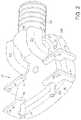
- FIG. 1shows a perspective view of a mask assembly of the present invention
- FIG. 2shows a front perspective view of a shell of the mask assembly of FIG. 1 ;
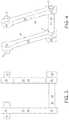
- FIG. 3shows a plan view of a portion of a latching mechanism of the mask assembly of FIG. 1 ;
- FIG. 4shows a perspective view of the portion of the latching mechanism of FIG. 3 ;
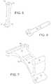
- FIG. 5shows a perspective view of a clip link of the latching mechanism of FIG. 3 ;
- FIG. 6shows a perspective view of a clip pin of the latching mechanism of FIG. 3 ;
- FIG. 7shows a perspective view of a clip portion of a latching mechanism of the mask assembly of FIG. 1 ;
- FIGS. 8A-8Care force diagrams showing the forces acting on the latching mechanism of the mask assembly of FIG. 1 ;
- FIG. 9Ashows a rear perspective view of the shell of FIG. 2 ;
- FIG. 9Bshows a sectional view of an alternative embodiment of the shell of FIG. 2 ;
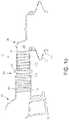
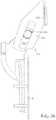
- FIG. 10shows a partial cut away side elevational view of a mask assembly of the present invention
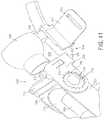
- FIG. 11shows a bottom rear perspective view of a portion of a head mount of the mask assembly of FIG. 10 ;
- FIGS. 12-16show a ball and socket joint of the present invention with FIG. 15 being a detail of FIG. 14 ;
- FIG. 17shows a rear perspective view of an alternative embodiment of the shell of the present invention.
- FIG. 18shows a front perspective view of an alternative embodiment of the shell of FIG. 17 and an alternative embodiment of the latching mechanism of the present invention
- FIG. 19shows a perspective view of a clip of the latching mechanism of FIG. 18 ;
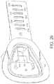
- FIG. 20shows a front perspective view of an alternative embodiment of the shell of the present invention.
- FIG. 21shows a top perspective view of an alternative embodiment of the shell of the present invention.
- FIG. 22shows a perspective view of an alternative embodiment of a mask assembly of the present invention installed on a user
- FIG. 23shows a side elevational view of the mask assembly of FIG. 22 ;
- FIG. 24shows a front perspective view of the mask assembly of FIG. 22 ;
- FIG. 25shows a perspective view of a head strap of the mask assembly of FIG. 22 ;
- FIG. 26shows a rear perspective view of a shell of the mask assembly of FIG. 22 ;
- FIG. 27shows a front perspective view of the shell of FIG. 26 ;
- FIG. 28shows a perspective view of a clip portion of a latching mechanism of the mask assembly of FIG. 22 ;
- FIG. 29shows a perspective view of a unitary clip link of the latching mechanism of the mask assembly of FIG. 22 ;
- FIGS. 30A and 30Bshow, respectively, a perspective view of the socket and a side elevational view of the ball of the mask assembly of FIG. 22 ;
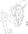
- FIG. 31shows a perspective view of an alternative embodiment of a head mount adjustment mechanism of the mask assembly of the present invention.
- FIG. 32shows a side elevational view of the head mount adjustment mechanism of FIG. 31 ;
- FIG. 33shows a front elevational view of the operation of the head mount adjustment mechanism of FIG. 31 ;
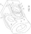
- FIG. 34shows a perspective view of an alternative embodiment of a head mount adjustment mechanism of the mask assembly of the present invention
- FIG. 35shows an enlarged perspective detail view of the head mount adjustment mechanism of FIG. 34 ;
- FIG. 36shows a rear perspective view of the head mount adjustment mechanism of FIG. 34 mounted to an alternative embodiment shell of the mask assembly of the present invention
- FIG. 37shows a side perspective view of the head mount adjustment mechanism and shell of FIG. 36 ;
- FIG. 38shows a front elevational view of the head mount adjustment mechanism and shell of FIG. 36 ;
- FIG. 39shows a side elevational view of the head mount adjustment mechanism and shell of FIG. 36 ;
- FIG. 40shows a front perspective view of an alternative embodiment of a head mount adjustment mechanism mounted to an alternative embodiment shell of the mask assembly of the present invention
- FIG. 41shows a perspective detail view of the head mount adjustment mechanism and shell of FIG. 40 ;
- FIG. 42shows a rear exploded view of the head mount adjustment mechanism and shell of FIG. 40 ;
- FIG. 43shows a front exploded view of the head mount adjustment mechanism and shell of FIG. 40 ;
- FIG. 44shows a side elevational view of a portion of the head mount adjustment mechanism of FIG. 40 ;
- FIG. 45shows a front perspective view of a portion of the head mount adjustment mechanism of FIG. 40 ;
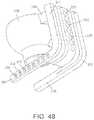
- FIG. 46shows a front elevational view of a connecting bracket of the head mount adjustment mechanism of FIG. 40 ;
- FIG. 47shows a side elevational view of the connecting bracket of FIG. 46 ;
- FIG. 48shows a rear perspective view of the connecting bracket of FIG. 46 ;
- FIG. 49shows a front perspective view of a locking bracket of the head mount adjustment mechanism of FIG. 40 ;
- FIG. 50shows a front elevational view of the locking bracket of FIG. 49 ;
- FIG. 51shows a side elevational view of the locking bracket of FIG. 49 ;
- FIG. 52shows a perspective view of an alternative embodiment of the mask assembly of the present invention.
- FIG. 53shows a side elevational view of the mask assembly of FIG. 52 ;
- FIG. 54shows a front elevational view of an alternative embodiment of a latching mechanism of the present invention.
- FIG. 55shows a bottom elevational view of the latching mechanism of FIG. 54 with the latching mechanism in a closed position
- FIG. 56shows a bottom elevational view of the latching mechanism of FIG. 54 with the latching mechanism in an open position
- FIG. 57shows a front elevational view of an alternative embodiment of a latching mechanism of the present invention.
- FIG. 58shows a bottom elevational view of the latching mechanism of FIG. 57 with the latching mechanism in closed and open positions;
- FIG. 59shows a perspective view of an alternative embodiment of the mask assembly of the present invention.
- FIG. 60shows a side elevational view of the mask assembly of FIG. 59 ;
- FIG. 61shows a front elevational view of the mask assembly of FIG. 59 ;
- FIG. 62shows a front perspective view of an alternative embodiment of a latching mechanism in a partially open position
- FIG. 63shows a front perspective view of the latching mechanism of FIG. 62 in a closed position
- FIG. 64shows a rear perspective view of the latching mechanism of FIG. 62 in a partially open position
- FIG. 65shows a sectional view of the mechanism used to secure the cushion to the shell
- FIG. 66shows a front view of the mask assembly of FIG. 59 installed on a user
- FIG. 67shows a side view of the mask assembly of FIG. 59 installed on a user
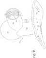
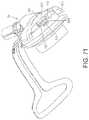
- FIG. 68shows a perspective view of an alternative embodiment of the mask assembly of the present invention.
- FIG. 69shows a front elevational view of the embodiment of FIG. 68 ;
- FIG. 70shows a side elevational view of the embodiment of FIG. 68 ;
- FIG. 71shows a bottom perspective view of the embodiment of FIG. 68 ;
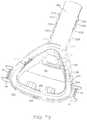
- FIG. 72shows a front perspective view of a mask shell of the embodiment of FIG. 68 ;
- FIG. 73shows a rear perspective view of the mask shell of the embodiment of FIG. 68 ;
- FIG. 74shows a front perspective view of a clip of a latching mechanism of the embodiment of FIG. 68 ;
- FIG. 75shows a rear perspective view of the clip of FIG. 74 ;
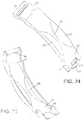
- FIG. 76shows a rear perspective view of a clip link of a latching mechanism of the embodiment of FIG. 68 ;
- FIG. 77shows a rear perspective view of a harness engaging clip of a latching mechanism of the embodiment of FIG. 68 ;
- FIG. 78shows a front perspective view of a harness engaging clip of a latching mechanism of the embodiment of FIG. 68 ;
- FIG. 79shows a sectional view of the latching mechanism and mask shell of the embodiment of FIG. 68 ;
- FIG. 80shows a perspective view of the embodiment of FIG. 68 ;
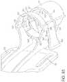
- FIG. 81shows a perspective view of a head support of the embodiment of FIG. 68 ;
- FIG. 82shows a perspective view of an adjustment clip of a head support adjustment mechanism of the embodiment of FIG. 68 ;
- FIG. 83shows a perspective view of a portion of a head support adjustment mechanism of the embodiment of FIG. 68 ;
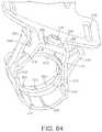
- FIG. 84shows a bottom perspective view of a portion of a head support adjustment mechanism of the embodiment of FIG. 68 ;
- FIG. 85shows a sectional view of a portion of a head support adjustment mechanism of the embodiment of FIG. 68 ;
- FIG. 86shows a bottom perspective view of a vent of the embodiment of FIG. 68 ;
- FIG. 87shows a top perspective view of the vent of FIG. 86 ;
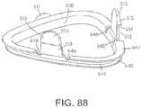
- FIG. 88shows a perspective view of a retaining ring of a cushion/shell connection mechanism of the embodiment of FIG. 68 ;
- FIG. 89shows a partial sectional view of a cushion/shell connection mechanism of the embodiment of FIG. 68 ;
- FIGS. 90A-90Dshows multiple views of the retaining ring in an alternate embodiment of the present invention.
- FIGS. 91A-91Cshows isometric views of the retaining ring of FIGS. 90A-90D ;
- FIG. 92shows a detailed view of the clip portion of the retaining ring of FIGS. 90A-90D ;
- FIG. 93shows on underside view of the retaining ring and clip of FIGS. 90A-90D ;
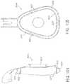
- FIGS. 94A-94Bshow top and back view of the retaining ring of FIGS. 90A-90D ;
- FIG. 95shows a perspective view of a cushion in an alternate embodiment of the present invention.
- FIG. 96shows a side view of the cushion of FIG. 95 ;
- FIGS. 97A-97Bshow side elevational views of the cushion of FIG. 95 ;
- FIGS. 98A-98Bshow front and perspective views of the cushion of FIG. 95 ;
- FIGS. 99A-99Bshow further front and perspective views of the cushion of FIG. 95 ;
- FIG. 100shows a sectional view of the cushion of FIG. 95 ;
- FIG. 101shows an exploded side view of an alternate embodiment of the present invention
- FIG. 102shows a front view of the cushion and ring assembly of the embodiment in FIG. 101 ;
- FIG. 103shows a exploded view of the cushion and ring assembly of FIG. 102 ;
- FIG. 104shows a side cross-sectional view of the mask in the alternate embodiment of FIG. 101 ;
- FIG. 105shows a rear view of the mask of FIG. 104 ;
- FIG. 106shows a front view of the mask of FIG. 104 ;
- FIG. 107shows the mask and ring assembly along a reference point 107 - 107 of FIG. 106 ;
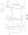
- FIG. 108shows a side view of alternate embodiment of FIG. 101 ;
- FIG. 109shows a cross-section view of an upper detent of the embodiment of FIG. 101 ;
- FIG. 110shows a cross-section view of a lower detent of the embodiment of FIG. 101 .
- FIG. 111shows a cross-sectional view of the alternate embodiment of the mask assembly shown in FIG. 101 ;
- FIG. 112shows a cross-sectional view of the alternate embodiment of the mask assembly shown in FIG. 101 ;
- FIG. 113shows a cross-sectional view of the alternate embodiment of the mask assembly shown in FIG. 101 .
- FIG. 1shows a perspective view of the mask assembly 10 of the present invention.
- the mask assembly 10includes a shell assembly 20 and a cushion 30 .
- One example of the type of cushion with a gusset that can be used with the present inventionis disclosed in U.S. patent application Ser. No. 09/885,445, “Mask with Gusset” to Frater et al. filed on Jun. 21, 2001, now U.S. Pat. No. 6,986,352 and assigned to the assignee of the present application, which application is incorporated by reference herein.
- a good seal with the facemay be obtained under a variety of pressures without the need to over tighten the straps of the mask.
- the gusset of the cushiondisconnects the frame contacting side of the cushion from the patient contacting side of the cushion and allows 6 degrees of freedom between the two sides.
- the present inventionis not restricted to use with such a cushion with a gusset and can be used with any NPPV therapy cushion. It should be understood that even where a Figure described herein does not show a cushion, only shows a portion of a cushion or only a gusset portion of a cushion, it is understood that such embodiment is intended to be used with a complete cushion and the use of the term cushion in describing a Figure that only shows a portion of a cushion is not intended to be limiting.
- the shell assembly 20includes a generally rigid shell 40 to which the cushion 30 can be attached.
- the shell 40includes a base 42 and a pair of flange assemblies 44 and 46 extending upward from the base 42 .
- the flange assemblies 44 and 46are generally mirror images of one another, although they need not be.
- Each of the flange assemblies 44 , 46includes an upper flange and a lower flange with a bore 50 passing therethrough, the bore preferably having an axis parallel to a major planar surface 52 of the shell 40 . See also FIG. 2 .
- Each of the flange assemblies 44 and 46support a quick-release latching mechanism 60 .
- Each latch mechanism 60preferably uses identical components to minimize the number of parts required to manufacture the mask assembly, although the components can be different where desirable.
- Each latching mechanism 60includes an upper clip link 62 and a lower clip link 64 , which are preferably identical but are reversed upon installation in the shell 40 . See also FIGS. 3-6 .
- Each clip link 62 , 64includes an axially extended body 66 with a first end 68 having a pivot pin 70 extending outward from the axially extended body 66 and having an axis perpendicular to an axis of the body 66 .
- each clip link 62 , 64also includes a second end 72 having a bore 74 therethrough, the bore 74 having an axis parallel to the axis of the pivot pin 70 .
- each latching mechanism 60also includes a clip pin 80 having an axially extending shaft 82 and an enlarged head 84 .
- the axially extending shaft 82is sized and adapted to pivotally engage the bores 74 of the respective upper and lower clip links 62 and 64 , respectively, of each assembly.
- the enlarged head 84provides a more easily graspable surface to assemble and disassemble the pin with respect to the latching mechanism and also provides an alignment surface to prevent the pin from passing too far through the bores 74 .
- each latching mechanism 60also includes a clip 88 .
- Each clip 88includes a first end 90 having a bore 92 therethrough sized and adapted to pivotally mount over the axially extending shaft 82 of the clip pin 80 between the upper and lower clip links 62 and 64 .
- Each clip 88also includes a second end 94 that includes a mask harness-engaging portion 96 .
- the harness-engaging portion 96preferably extends away from a central portion of the clip 88 at an angle toward a face side of the mask 10 generally in alignment with an angle of the harness portion extending from the user's head toward the harness-engaging portion 96 . See FIG. 8A .
- the harnesswill exert a pulling force Fu on the harness-engaging portion 96 of the clip 88 that is generally aligned with the angle of the harness-engaging portion 96 .
- the harness-engaging portion 96may be a slot through which a portion of the harness can pass to be secured to the clip 88 .
- the harnessmay include an engaging strap that can pass through the harness-engaging portion 96 and then be connected to itself by use of Velcro®, snap connections, buckles or other known connections.
- Each clip 88includes a flip arm 98 extending away from a body of the clip 88 that is easily graspable by the mask user to manipulate the clip 88 with respect to the mask 10 .
- Each clip 88may optionally be provided with a stop surface 95 that may be adapted to engage the shell 40 or other fixed portion of the shell assembly 20 to provide a positive stop to movement of the clip 88 in a direction toward the shell 40 .
- Each latching mechanism 60may be assembled to the shell 40 as follows.
- the upper and lower clip links 62 and 64are first pivotally mounted to the respective upper and lower flanges of the flange assemblies 44 , 46 by engaging the respective pivot pins 70 with the respective portion of the bores 50 passing through the upper and lower flanges.
- the clip 88is then inserted between the upper and lower clip links 62 and 64 .
- the width of the clip 88is established so that once the clip 88 is inserted between the upper and lower clip links 62 , 64 , the clip 88 will prevent the clip links 62 , 64 from disengaging from the respective flanges 44 , 46 .
- the bore 92 of the clip 88is then aligned with the respective bores 74 of the upper and lower clip links and the clip pin 80 is inserted through each of the bores to pivotally mount the clip 88 with respect to the clip links 62 , 64 and the flange assemblies 44 , 46 .
- the latching mechanism 60works on an over-center principle. That is, when a pulling force F H from the harness is applied to the harness-engaging portion 96 of the clip 88 , the clip 88 will have a tendency to move in a direction away from a force equilibrium or force center position of the latching mechanism. In the embodiment shown in FIGS. 8A-8C , the force equilibrium or force center is on a line intersecting the axes of the shaft 82 and the pins 70 . If the summation of forces acting on the clip 88 result in a summed force component acting on the shaft 82 that extends at an angle below the axis of pins 70 , such as F L , seen in FIG.
- the clip 88will be maintained in a bottomed or latched position against the shell 40 . However, if the summation of forces acting on the clip 88 result in a summed force component acting on the shaft 82 that extends at an angle above the axis of pins 70 , such as F U seen in FIG. 8A , the clip 88 will move toward an open or unlatched position, as shown in FIG. 8B .
- the clip 88will remain in the latched position.
- a release force F Ris exerted on the clip by the user or other person such that the summation of forces F R and F H result in a summation force F U
- the clip 88will move to the unlatched position.
- the angle of the force F His altered such that the summation force acting on the clip 88 changes from F L to F U , the clip 88 will also move from the latched to the unlatched position.
- each latching mechanismprovides 60 slack in the harness of approximately two times the distance between the axes of pins 70 and shaft 82 .
- the shell 40includes an extension 41 over which the strap of the harness must pass to prevent the strap from pulling directly downward on the clip 88 and thereby possibly unintentionally providing the necessary force to unlatch the latching mechanism 60 .
- the extensionsprevents the strap from applying a pulling force F H on the clip in an undesired direction.
- the use of the quick-release latching mechanism 60 as described aboveprovides for a low-profile attachment mechanism between the shell 40 and the harness, while also allowing the attachment to be quickly, accurately, repeatedly and easily released and latched.
- the latching mechanism 60assures that the preset strap adjustment is maintained over repeated latchings and unlatchings. That is, once the strap is adjusted properly for the user, the latching mechanism 60 allows the user to remove and reinstall the mask assembly 10 and maintain the same preset strap adjustment, unlike known mask systems. Further, the slack provided in the harness when each latching mechanism 60 is unlatched also makes it easier for the user to place the mask assembly 10 on the head and to remove it from the head.
- the design of the latching mechanismsmay also be configured to permit the latching mechanisms 60 , and thus the straps, to be quickly removed from the shell by placing the latching mechanism 60 in the unlatched position and removing the pins 70 from the bore 50 .
- the shell 40may also includes a number of other features.
- the shell 40may include an air inlet tube 100 connected to an upper central portion of the shell 40 and having a port 102 opening to an interior of the mask assembly 10 at an upper central position on the shell 40 to supply breathable gas from a pressurized supply to an interior of the mask assembly 10 . See FIGS. 1, 2 and 9 .
- the air inlet tube 100may include an external thread 101 for connecting the air inlet tube 100 to further components of the air supply path.
- the shell 40may also include a pair of exhalation ducts 104 positioned on respective sides of the air inlet tube 100 for exhausting gases from the mask assembly 10 .
- Each exhalation duct 104includes a port 106 opening to an interior of the mask assembly 10 at a position toward the respective side of the shell 40 .
- the air inlet tube opening port 102is separated from the exhalation duct opening ports 106 by a pair of raised walls 108 extending from an interior surface 110 of the shell 40 .
- the raised walls 108extend from a position adjacent the air inlet tube opening port 102 downward along the shell 40 while angled outward as they extend downward to provide clearance for the user's nose.
- the raised walls 108stop before reaching a bottom edge 116 of the shell 40 .
- the raised walls 108define a central gas intake channel 112 in the mask through which the pressurized gas can flow to the user's nostrils.
- the raised walls 108also define a pair of lateral gas exhaust channels 114 within the mask but outside of the central gas intake channel through which exhalation gases can flow to the exhalation ducts 104 .
- the raised walls 108improve air flow in the mask by separating the intake gas from the exhalation gas in the mask to help reduce the short-circuiting of oxygen-rich intake gas to the exterior of the mask through the exhalation ducts.
- the positioning of the exhalation duct opening ports 106 to the outside of the central air inlet tube opening port 102 with the raised walls 108 positioned therebetweenutilizes the natural flow of gas in the mask. That is, when the user is inhaling, the gas can flow through the central channel to the user's nostrils. However, when the user exhales, the exhaled gas will flow from the nostrils downward, hitting the bottom edge of the shell and moving outward along the bottom edge of the shell and into the pair of lateral gas exhaust channels.
- the flow management provided by the raised walls 108not only reduces short-circuiting of the intake air to the exhalation ducts 104 , it reduces carbon dioxide levels in the mask and also assists in moving the exhalation gas from the user's nostrils to the exhalation ducts 104 while minimizing exhalation backwash into the intake charge.
- the shell 40may be provided with a single centrally positioned exhalation duct 104 having a port 106 positioned beneath the air inlet tube opening port 102 and separated by a central baffle 109 .
- the exhalation ducts 104may be curved upward and have exhaust ports 120 facing upward with respect to the shell 40 alongside the air inlet tube 100 . In this way, the exhalation ducts 104 receive the exhalation gas from the interior of the mask and channel such gas out of the exhaust ports 120 , upward alongside the air inlet tube 100 .
- the channeling of the exhalation gases to the exterior of the mask in this mannerprovides an exhaust flow that follows the air inlet tube upward. This minimizes exhaust flow either toward the mask user's face or toward a bed partner of the user, as can happen with conventional masks that exhaust gas from the front of the mask and which can be disturbing to bed partners when the user is facing the bed partner. Also, locating the exhaust ports farther from the user's nostrils helps reduce breathing noise that escapes from the mask.
- the curving of the exhalation ducts 104 upward such that the exhaust ports are remote from the base of the shellcan allow greater ease in configuring the cross-section of the exhaust ports for enhanced sound reduction and the accommodation of exhalation diffusers within the mask.
- the shell 40may also include a pair of access ports 118 located at a bottom of the mask 10 .
- the access ports 118are connectable to one or more supply tubes through which medication or oxygen can be supplied to an interior of the mask.
- the access ports 118may also be used to access an interior of the mask 10 for control or measurement purposes, such as to measure a mask interior pressure. CO 2 levels, etc. While two such ports are shown, the number of access ports can be altered as is desired. When not in use, the access ports 118 can be capped to prevent leaks from the interior of the mask.
- the access ports 118may also be positioned at an upper portion of the shell so that the supply tubes can run alongside the air inlet tube 100 and minimize tangling of the tubes or can be positioned elsewhere on the mask assembly 10 as desired.
- FIG. 10shows a partial cutaway side elevational view of an overall mask assembly 10 .
- the mask assembly 10also includes a head mount 130 and head mount height adjuster 146 .
- the head mount 130 and adjuster 146provide a connection between an air supply tube 100 and the mask assembly 10 .
- the head mount 130includes a base portion 132 for contacting the user's forehead.
- the base portion 132is curved to conform generally to the shape of a user's forehead.
- a foam or other soft layermay be provided on an underside surface of the base portion 132 to increase the comfort of the user when wearing the mask assembly 10 .
- the base portion 132also includes three slots 134 and 136 for connecting the head mount 130 to the harness to secure the head mount 130 to the user's head.
- the two laterally positioned slots 134mount to portions of the harness extending from around the sides of the user's head, while the centrally positioned slot 136 mounts to a portion of the harness extending from the top of the user's head.
- Other types of connectorsmay also be used to connect the head mount 130 to the harness, such as snap connections, hook connections, Velcro®. connections or other connections.
- the head mount 130further includes a pedestal 138 mounted to the base portion 132 .
- the pedestal 138supports a ball and socket joint socket joint 200 flowingly connected to an air connector tube 142 .
- the ball and socket jointwill be described in detail below.
- the air connector tube 142includes a thread 144 for connecting to the height adjuster 146 .
- the head mount height adjuster 146is generally configured as a hollow tube to permit air flow from the head mount 130 to the air inlet tube 100 .
- Head mount adjuster 146includes a first threaded portion 148 for connecting to the threaded portion 101 of air inlet tube 100 and a second threaded portion 150 for connecting to the threaded portion 144 of air connector tube 142 .
- the height adjuster 146also includes a centrally mounted finger wheel 152 for rotating the adjuster 146 to adjust the spacing between the head mount 130 and the shell assembly 20 .
- one of threaded portions 148 and 150is right-hand threaded and the other is left-hand threaded, as are the respective corresponding threaded portions of the air inlet tube 100 and the air connector tube 142 , so that the distance between the head mount 130 and the shell assembly 20 can be altered by rotating the adjuster 146 only, and without rotating either the head mount 130 or the shell assembly. See FIG. 10 .
- This featuremakes it easy for the user to adjust the spacing between the head mount 130 and the shell assembly 20 for the best fit and comfort once the mask assembly 10 has been placed on the user's head without the need for removing the mask assembly to rotate either the head mount 130 or the shell assembly 20 with respect to one another as would be necessary if all of the threaded portions were right-handed or left-handed.
- the threaded portionsmay be made all right-handed or left-handed. Further, the internal and external threaded portions of the respective mating components may be reversed. It is preferred that the threaded connections between the air inlet tube 100 , the height adjuster 146 and the air connector tube 142 be of a sufficiently close tolerance such that any substantive air leaks at the joints may be prevented. Further, adjustment will remain as set under normal wearing conditions, and the tolerances are not so tight as to prevent ready rotation of the adjuster 146 with only the user's fingers when the user desires to alter the adjustment.
- the shell 40is made of polycarbonate
- the latching mechanism 60 componentsmay be made of a semi-rigid plastics material such as acetal or nylon
- the head mount 130may be made of acetal or polypropylene.
- the various componentscan also be made of other known materials.
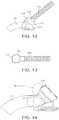
- FIGS. 12-16The ball and socket joint 200 is shown in detail in FIGS. 12-16 .
- the ball and socket joint 200is mounted closer to a base plate 202 and includes a curved air connector tube 214 .
- FIG. 12shows a ball and socket joint 200 attached to a base plate 202 that can be attached to the patient's forehead with the harness/headgear.
- the ball and socket joint 200may be mounted directly to the mask shell 40 or can be attached only to an air supply tube connected to the air inlet tube 100 of the shell 40 .
- the ball and socket joint 200can freely move, as it is not rigidly attached to the shell 40 or some other stationary structure.
- the joint 200includes a ball 204 mounted on the end of flexible air tube 206 .
- the air tube 206maybe adapted for connection with a pressurized air source.
- the ball 204is adapted for mounting in a socket 208 .
- Pressurized air from the air tube 206flows through an orifice 210 in the ball 204 into the socket 208 and through an orifice 212 in the socket 208 to the mask 10 through tube 214 .
- the socket 208includes an inner circumferential seat 216 and a lip 218 at an outer edge of the socket 208 .
- the ball 204can be relatively easily inserted into the socket 208 and removed, if necessary. Once the ball 204 is inserted into the socket 208 , it rests between the seat 216 and the lip 218 with a small clearance provided between the ball 204 and the seat 216 and lip 218 of the socket.
- the small clearance provided between the ball 204 and the seat 216 and lip 218 of the socket 208allows the ball 204 to move or rotate freely with respect to the socket 208 . While the ball 204 is in motion, the clearance allows a small amount of the pressurized air to escape between the ball 204 and socket 208 to the atmosphere. However, once the ball 204 is in a static position, the air pressure forces the ball 204 against the lip 218 and seals the connection between the ball 204 and socket 208 until the ball 204 is again placed in motion. See FIG. 16 .
- the ball and socket joint 200allows the air supply tube to be moved about the socket 208 anywhere in a range of movement in the form of a cone projecting from the socket and provides increased movement of the air tube over a conventional elbow swivel joint.
- the ball and socket joint 200may be formed by methods and materials well known in the art, such as, for example, polypropylene. This material has the advantage of having a soft wax-like surface texture, which helps reduce noise between the part s during movement.
- the ballcan also preferably be made of polycarbonate.
- the ball and socket joint 200may, like the remainder of the invention, be manufactured of any of the materials known to be used for the production of such joints or mask parts, although it is preferred that one of the ball and socket be made from a relatively rigid material and the other made from a relatively flexible material for best operation.
- FIGS. 17 and 18An alternative embodiment of the shell 40 is shown in FIGS. 17 and 18 .
- an internal wall 160 of the shell 20has been given an increased height such that this internal wall 160 will project into the cushion 30 .
- This embodimentis especially designed for use with a gusseted cushion, as discussed above and shown in FIGS. 1 and 10 .
- the internal wall 160is configured so as to project into the gusset portion 32 of the cushion without actually contacting the interior of the gusset portion 32 so as not to interfere with pressurization and movement of the gusset portion 32 of the cushion 30 .
- This projection into the gusset portion 32helps maintain alignment of the cushion 30 with the shell 40 when the gusset is in a deflated or closed state.
- the projectionneed not be continuous around the periphery to provide effective alignment and can include separate independent projecting portions to achieve the same result.
- FIGS. 17 and 18also includes a flange 162 extending around a periphery of the shell 40 .
- This flange 162contacts a front side of the gusset portion 32 of cushion 30 when the mask is in use and effectively stiffens the gusset portion 32 of the cushion 30 to provide more force on the face from the cushion.
- This featureis further described in U.S. patent application Ser. No. 09/885,445, “Mask with Gusset” to Frater et al. filed on Jun. 21, 2001, now U.S. Pat. No. 6,986,352 discussed above.
- the shell 40 in this embodimentis also provided with exhalation ducts 104 of an increased size.
- the air inlet tube 100is also shortened in this embodiment as compared to the embodiment of FIG. 2 .
- FIGS. 18 and 19an alternative embodiment of the clip 88 is shown in FIGS. 18 and 19 .
- the flip arm 98is positioned generally directly over the bore 92 , instead of intermediate bore 92 and end 94 as in the embodiment shown in FIG. 7 .
- the flips arms 98are closely adjacent one another. This allows both flip arms 98 to be grasped simultaneously between the thumbs and forefingers of the user when in the closed position and moved to a position where the latching mechanisms 60 will both unlatch and open.
- Each flip arm 98also has a lower height to reduce the chance that the flip arm 98 will become entangled in the bed linens and unintentionally unlatch the latching mechanism upon movement of the user or bed linens.
- the flip armis provided with grasping extensions 99 on both sides.
- the grasping extensions 99are preferably dished to allow secure grasping of the flip arm 98 between the user's thumb and forefinger.
- This embodiment clip 88does not include a stop surface 95 in order to better conform to the flatter upper surface of the shell 40 shown in FIG. 18 .
- FIGS. 20-21An alternative embodiment of the shell 40 is shown in FIGS. 20-21 .
- the exhalation ductsare further increased in size to increase a cross-sectional area of the exhaust ports 120 , reducing exhalation gas velocity and/or providing additional space for an exhalation gas diffuser.
- FIGS. 22-29show an alternative embodiment of the mask assembly 10 .
- the mask assemblydoes not use a separate head mount as the embodiment discussed above.
- the shell 40includes an extension bracket 220 extending from an upper portion of the shell 40 .
- the extension bracket 220is generally rectangular but may have other configurations as well.
- the extension bracket 220is configured to engage a retaining channel 222 of a head strap 224 . Because the sides of the extension bracket 220 and the retaining channel 222 are generally parallel, the head strap 224 can be moved up and down the extension bracket 220 to adjust the distance between the head strap 224 and the main body of the shell 40 /cushion 30 . This allows the head strap 224 to be adjusted to properly fit the user. Compare FIG. 23 and FIG. 24 depict different adjustments that may be made to the head strap 224 along the extension bracket 220 .
- the head strap 224also includes a pair of raised projections 232 positioned in the retaining channel 222 adapted to engage any one of a plurality of detent slots 234 positioned along an under side of the extension bracket 220 .
- the head strap 224will be maintained in this adjusted position, under normal wearing conditions, until the user re-adjusts the head strap 224 with respect to the extension bracket 220 .
- the height of the projections 232is established in connection with the flexibility of the head strap 224 such that the projections 232 may be moved from one detent slot 234 to another without requiring undue force to make such an adjustment.
- the head strap 224also includes a retaining loop 226 mounted above the retaining channel 222 .
- the retaining loop 226is sized to engage and retain a connector tube 228 connecting the air inlet tube 100 with a ball and socket joint 200 .
- the positioning of the ball and socket joint 20 X), with respect to the shell 40is reversed as compared to the embodiments shown above. If desired, the positioning can be as discussed above.
- the retaining loop 226thus supports both the connecting tube 228 and the ball and socket joint 200 .
- the head strap 224includes a plurality of adjustment slots 230 and adjustment slots 231 on both free ends.
- the adjustment slots 230are for connecting to side portions of a harness or retaining strap extending between the free ends of the head strap 224 and the adjustment slots 231 are for connecting to top portions of a harness or retaining strap extending between the free ends of the head strap 224 to secure the head strap 224 to the user's head.
- the head strap 224includes the retaining channel 222 on an outside surface thereof, the inner surface of the head strap 224 may be kept generally smooth.
- the head strap 224does not actually contact the user's forehead but floats in front of the user's forehead.
- the gusset portion of the cushion 30is inflated, the shell 40 is pushed away from the user's face, placing tension on the head strap 224 being held in place by the harness extending between free ends of the head strap 224 .
- This tensionpulls the head strap 224 away from the user's forehead. This results in increased comfort for the user, since there is less contact with the user's face and also prevents unsightly pressure marks from occurring on the user's forehead due to contact with the mask assembly 10 , as can occur with known mask assemblies.
- the access ports 118are positioned closer together and more centrally on the shell 40 than in the previous embodiments.
- the access ports 118also extend from a front of the shell 40 , as opposed to a bottom of the shell 40 .
- the shell 40 in this embodimentalso includes a flange 162 extending around its periphery to contact and support the gusset portion of the cushion 30 and stiffen the action of the gusset portion.
- each latching mechanism 60 in this embodimentreplaces the two clip links 62 , 64 and pin 80 of the embodiment shown in FIGS. 1-7 with a unitary clip link 240 .
- Each latching mechanism 60also includes a clip 88 , similar to the clip shown in FIGS. 1-7 except as described below. See FIG. 28 .
- the unitary clip link 240depicted in FIG. 29 , includes two pins 70 for engaging bore 50 of the respective flange assembly.
- the two pins 70are mounted on pin arms 71 extending freely away from a central portion of the link 240 to provide a spring action so that they can be squeezed toward one another to allow clearance for inserting the pins 70 in the bore 50 .
- unitary clip link 240includes two inwardly facing pins 83 for engaging bore 92 in clip 88 .
- the pins 83are mounted on pin arms 85 extending away from a central portion of the link 240 to provide a spring action so that they can be flexed outward to provide clearance for inserting the pins in the bore 92 .
- the unitary clip link 240also includes a pair of centrally positioned side extensions 242 . These side extensions 242 engage inner surfaces of the flange assemblies when the latching mechanism 60 is latched to provide lateral stability to the latching mechanism 60 .
- the unitary clip link 240also includes a third extension 244 extending between pin arms 85 toward pins 83 and a fourth extension 216 extending between pin arms 71 .
- the third extension 244includes an extending tab 245 that is adapted to engage a slot 89 on clip 88 .
- the slot 89is configured such that an end surface of the slot 89 contacts the tab 245 when the latching mechanism 60 has reached full extension in the open position to provide a positive stop to further movement of the latching mechanism 60 .
- the slot 89can also be configured to provide a positive stop to the tab 245 when the latching mechanism 60 is in the closed position.
- Extensions 242 , 244 and 246all act to limit excessive movement of adjacent pin arms 71 and 85 and provide underlying support to the clip 88 when the latching mechanism 60 is in the closed position.
- Clip 88can also be optionally provided with a protrusion 91 on an underside surface to contact extension 246 and provide a further stop mechanism when the latching mechanism 60 is in the closed position.
- FIG. 30shows the ball 204 and socket 208 of the embodiment of the ball and socket joint 200 shown in FIGS. 22-24 .
- FIGS. 59-61 and FIGS. 66-77show an alternative embodiment of the mask assembly 10 of the present invention.
- the shell 40includes an extended air inlet tube 100 .
- a head strap 450includes a connecting member 460 to which are connected a front harness mount 452 for connecting to a harness, an upper harness mount 456 for connecting to the harness and an upper head mount 454 for contacting an upper portion of the user's head to position and stabilize the head strap 450 .
- Each of the harness mounts 452 and 456include slots 458 for connecting to the harness 461 (see FIGS. 66 and 67 ), although other attachment mechanisms may also be used.
- FIGS. 66 and 67show an alternative embodiment of the mask assembly 10 of the present invention.
- FIGS. 59-61 and FIGS. 66-77show an alternative embodiment of the mask assembly 10 of the present invention.
- the shell 40includes an extended air inlet tube 100 .
- a head strap 450includes a connecting member 460 to which are connected a front harness
- the harness 461is shown as only connecting to the front harness mount 452 .
- the harness 461can be configured to connect to both harness mounts 452 and 456 .
- the front harness mount 452includes a split retaining loop 462 that is adapted to slidingly connect to the extended air inlet tube 100 .
- the shell assembly 20 and cushion 30are connected to the head strap 450 and can be adjusted vertically with respect to the head strap 450 to fit the mask assembly 10 to the particular user.
- the latching mechanisms 60are similar to the latching mechanisms 60 discussed above with respect to FIGS. 22-29 .
- each flip arm 98 of each clip 88is configured so that when both latching mechanisms 60 are in the closed position, the flip arms 98 are positioned closely adjacent one another and upper and lower edges of each flip arm 98 are raised sufficiently to be readily grasped between the user's thumb and forefinger.
- both flip arms 98can be grasped between the thumb and forefinger of the user and simultaneously manipulated with one hand to unlatch each latching mechanism 60 and quickly allow each latching mechanism 60 to move to the open position using only the one hand.
- any of the latching mechanisms 60 described hereinmay be modified to include a positive latch that will hold the latching mechanism in the latched position.
- the positive latchcan be a detent mechanism between the latching mechanism and the shell that positively holds the latching mechanism in the latched position until unlatched by the user.
- Such a positive latch mechanismmay be configured to provide an audible indicator, such as a click, or other sensory indicator, that indicates that the latching mechanism is in the fully latched position.
- the head strap 450 and air inlet tube 100may be provided with a detent mechanism similar to the detent mechanism discussed above with respect to the embodiment shown in FIGS. 22-29 to maintain an adjusted position between the head strap 450 and the air inlet tube 100 .
- the air inlet tube 100 and the retaining loop 462may be threaded to provide an adjustable connection between the two components capable of maintaining the adjusted position.
- FIGS. 62-64show an alternative embodiment of the latching mechanism 60 and shell assembly 20 .
- only one latching mechanism 60is used.
- the clip 88is pivotally mounted to a clip link 240 , which is pivotally mounted to the shell 40 .
- the clip 88includes a second end 94 having a mask harness-engaging portion 96 .
- the single latching mechanism 60 of the present embodimentis approximately twice as long as each latching mechanism discussed above.
- the clip 88 and the clip link 240 of this embodimentare approximately twice as long as each clip 88 and clip link 240 shown in the embodiment of FIGS. 22-29 .
- the clip 88can optionally include a flip arm 98 for manipulating the clip 88 , similarly to the previous embodiments. However, since the first end 90 of the clip 88 extends generally to the other side of the shell 40 when in the closed position because of the increased length of the clip 88 and clip link 240 , the latching mechanism 60 can also be unlatched by manipulating the exposed first end 90 of the clip 88 .
- a harness-engaging clip 470is provided in this embodiment to engage the second side of the harness.
- the harness engaging clip 470includes a pair of inwardly extending pins 472 to pivotally engage the bore 50 of the shell 40 , as does the left latching mechanism of the embodiments discussed above, and a mask harness engaging portion 474 for engaging the harness.
- the harness engaging clip 470does not interfere with the latching mechanism 60 when in the closed position, even though the width of the clip link 240 is preferably set so as to engage the inner sides of the flange assembly 44 in the closed position to provide stability to the latching mechanism 60 .
- a fixed harness-engaging portioncan be provided on the shell itself, but with the present embodiment, the same shell 40 can be used in either a double or a single latching mechanism mode.
- the latching mechanism 60can be attached to the shell 40 on either side of the shell 40 , as can the harness engaging clip 470 , to provide left and right handed mask versions, using the identical components.
- two latching mechanisms 60 of the increased lengthcan be provided on the shell 40 with one latching mechanism positioned by an extended flange assembly to be further out from the shell 40 than the other latching mechanism such that the more outwardly positioned latching mechanism can overlay the inner latching mechanism.
- the inner latching mechanismIn a latching mode, the inner latching mechanism would first be manipulated to the closed position and then the outer latching mechanism. In an unlatching mode, the process would be reversed.
- the inner latching mechanismcan be provided with a grasping member that does not interfere with movement of the outer latching mechanism such that manipulation of the grasping member by the user opens the inner latching mechanism, which in turn, simultaneously opens the outer latching mechanism.
- Each of the latching mechanisms described hereinoperate on the same over center principal as described with respect to FIGS. 8A and 8B .
- FIGS. 31-32show an alternative embodiment of a head mount adjustment mechanism 250 .
- the mechanismincludes a pair of generally parallel extending spring tabs 252 extending from the shell 40 (only a portion of which is shown) on opposite sides of the air inlet tube 100 .
- a generally round locking gear 254is fixedly mounted to a distal end of each spring tab 252 and, in the preferred embodiment, is integrally cast with the spring tab 252 .
- a plurality of teeth 256are evenly spaced around a periphery of each locking gear 254 .
- the locking gears 254are coaxial with one another and each locking gear 254 has a raised projection 258 for manipulation of the locking gear/spring tab assembly by the user.
- Head mount 260includes a base 262 for engaging a user's forehead and slots 264 or other attachment mechanisms for attaching the head mount 260 to a head strap or harness.
- the head mount 260also includes a pair of generally parallel extending brackets 266 .
- Each extending bracket 266includes an elongated slot 268 passing therethrough with longitudinal axes of the elongated slots 268 being generally parallel to one another.
- Each elongated slot 268includes a pair of generally straight, parallel opposing rows of locking teeth 270 .
- the locking teeth 270 and locking gear teeth 256are each configured so that they can readily and stably engage each other.
- the pitch of the locking teeth 270is set to correspond to the pitch of the locking gear teeth 256 and the distance between the rows of teeth 270 is set to correspond to a diameter of the locking gear 254 to provide proper engagement between the teeth 270 and the gear 254 .
- the locking teeth 270have generally rounded crowns 275 and more pointed roots 277 while the teeth 256 correspondingly have more pointed crowns 276 and generally rounded roots 278 .
- Other gear shapes and configurationscan also be used.
- the locking gear 254can be engaged with the rows of teeth 270 at a plurality of discrete points along substantially all of the length of the slot 268 , thereby altering a distance between the head mount 260 and a main body of the shell 40 .
- This configurationalso allows the angle of the head mount 260 with respect to the shell 40 to be altered (again within the limitations imposed by the pitch of the teeth) by engaging the teeth 270 with different teeth 256 around the locking gear 254 .
- This angledoes not extend entirely around the locking gear 254 since, at some point, some portion of the head mount 260 will contact and be stopped by some portion of the shell 40 or cushion 30 . However, this is of little concern because in most instances for most users, the desired angle of the head mount 260 with respect to the shell 40 will fall within a limited range of substantially less than 90°.
- both the distance and the angle between the head mount 260 and the shell 40can either be altered simultaneously or altered independently of one another to provide the desired fit for the user.
- the spring tabs 252while fairly rigid, are flexible enough such that when the user squeezes the opposing projections 258 extending above the slots 268 , the spring tabs will move toward one another, thereby disengaging the locking gear 254 from the locking teeth 270 . See FIG. 33 .
- the desired distance and angle between the head mount 260 and shell 40can then be set as desired and the spring tabs 252 released to engage the locking gear 254 with the locking teeth 270 and lock the head mount 260 in the desired position.
- the degree of flexibility of the spring tabs 252can be altered by altering a thickness, material and/or shape thereof.
- an outer edge of the teeth 256 and/or an inner edge of the teeth 270can be rounded.
- the thickness of the teeth 256 and 270and thus the amount of engagement between the respective teeth, will be set based on the magnitude of forces that the adjustment mechanism is expected to encounter in use, with higher expected forces suggesting thicker teeth and greater engagement between the respective teeth.
- one or more support members 272can interconnect the extending brackets 266 .
- the head mountincludes a passageway 274 positioned between the extending brackets 266 so that an air supply tube can be routed therethrough for connection to the air inlet tube 100 .
- ends of the slots 268can be radiused, as shown at 276 , to provide increased clearance for the locking gear 254 , thereby allowing an increased length of engagement between the locking gear 254 and the rows of teeth 270 .
- the interacting structures on the head mount 260 and the shell 40can be reversed.
- each locking gear 254is provided with a generally cylindrical projection 278 .
- the projection 278has an outer diameter approximately the same or slightly less than the distance between the crowns of opposing rows of teeth 270 and a height that extends beyond the slot 268 , preferably by a sufficient distance such that when the spring tabs 252 are squeezed together for adjustment of the mechanism 250 , the projections 278 remain engaged with the teeth of their respective slots 268 . In this way, increased stability is provided between the head mount 260 and the shell 40 during adjustment of the mechanism 250 since the projections 278 remain movably engaged with the rows of teeth 270 even though the locking gear 254 is disengaged from the rows of teeth 270 .
- a distal end 280 of each slot 268is curved and provided with teeth 270 such that when the distance between the head mount 260 and the shell 40 is adjusted to its maximum, there is engagement between the teeth 270 and the teeth 256 around 180° of the locking gear 254 .
- This increased engagementprovides additional stability to the adjustment mechanism 250 at a time when the increased distance between the head mount 260 and the shell 40 is acting to decrease stability of the adjustment mechanism 250 .
- the curved, toothed distal end 280 of the slot 268also continues to provide angular adjustment ability to the mechanism 250 at the maximum adjustment distance of the mechanism 250 .
- further raised projections 258are not needed for manipulation by the user and the projections 278 can optionally be dished or hollow for material savings.
- the teeth 256 and 270have a slightly different configuration than in the previous embodiment and the outer diameter of each projection is approximately the same as the root diameter of the locking gear 254 .
- FIGS. 36-39show perspective views of the adjustment mechanism 250 with an alternative embodiment of the shell 40 .
- one exhalation duct port 106is provided below air inlet tube port 102 with a laterally extending baffle 282 extending therebetween to separate the two gas flows through these ports.
- the duct port 106connects to a single exhalation duct 104 that extends upward and partially surrounds the air inlet tube 100 with exhalation gases exiting through a single exhaust port 120 .
- FIGS. 40-51show an alternative embodiment of a head mount adjustment mechanism 300 .
- a shell portion 302 of the adjustment mechanismmay be the same as any of the shell embodiments shown in FIGS. 31-39 and includes spring tabs 252 , locking gears 254 and a plurality of locking teeth 256 positioned around a periphery of the locking gear 254 .
- the shell 40may be changed if desired.
- a head mount portion 304 of the adjustment mechanism 300is different from the previous embodiments.
- the head mount portion 304includes a locking bracket 306 having a pair of generally parallel extending brackets 266 .
- Each extending bracket 266includes a generally round slot 268 passing therethrough with the two slots 268 being generally coaxial to one another.
- Each slot 268includes plurality of locking teeth 270 positioned around an inner circumference of the slot positioned and configured to engage the teeth 256 in a locking manner. Since each slot 268 is round, the engagement between the teeth 270 and the teeth 256 of this embodiment only allow for changes of an angle between the locking bracket 306 and the shell 40 and does not allow for a height adjustment between the two components. This angle can be adjusted by depressing the spring tabs 252 and rotating the locking bracket 306 in the same manner as was described above with respect to the previous embodiments.
- the locking bracket 306includes a retaining channel 308 sized and configured to slidingly receive a first extending tab 310 of a connecting bracket 312 .
- the connecting bracket 312includes a second extending tab 315 extending at an angel with respect to the first extending tab 310 .
- the connecting bracket 312is generally L-shaped, although the angle between the first and second extending tabs need not be 90°, and in the preferred embodiment, is closer to 100°. However, any angle can be chosen that provides the best fit for the intended user.
- the first extending tab 310is relieved for much of its distal extent to provide clearance for an air tube although such clearance can also be provided by an enclosed slot on the tab 310 .
- Each side of the tab 310includes a plurality of spaced apart detent slots 314 .
- locking bracket 306includes a pair of detent spring arms 316 , each having a raised detent projection 318 projecting into the retaining channel 308 from opposing sides and adapted to engage respective pairs of the detent slots 314 to lock the connecting bracket 312 in a desired adjusted position with respect to the locking bracket 306 . While the locking bracket preferably uses two detent spring arms 316 , one or more spring arms can optionally be used.
- the raised detent projections 318be positioned at the end of spring arms to ease movement, adjustment and longevity of the components, the raised detents need not be on spring arms and can be merely positioned on opposing interior walls of the retaining channel 308 .
- the position of the connecting bracket 312can be adjusted fore and aft with respect to the locking bracket/shell/cushion, which in turn, adjusts the fore and aft position of a head mount 320 attached to the connecting bracket 312 with respect to the locking bracket/shell/cushion, by sliding the tab 310 within the retaining channel 308 until the raised projections 318 engage the detent slots 314 in the desired position and lock the connecting bracket 312 with respect to the locking bracket 306 .
- the raised detent projections 318 and/or the detent slots 314can be chamfered to lessen the amount of force required to move the connecting bracket 312 with respect to the locking bracket 306 .
- the size, shape and configuration of the spring arms 316can be altered to vary a spring force imparted by the spring arms 316 on the raised projections 318 to adjust the force required to move the connecting bracket 312 within a desired range.
- the distal end of tab 310can be chamfered for ease of insertion into retaining channel 308 .
- the second extending tab 315 of connecting bracket 312includes a centrally positioned row of spaced apart detent slots 322 that are adapted to engage a detent projection 324 positioned in a first retaining channel 326 of head mount 320 .
- the detent projection 324is not shown positioned on a spring tab, it can be where desired.
- second extending tab 315is adapted to engage retaining channel 326 of head mount 320 to provide a generally vertical adjustability to the head mount 320 with respect to the connecting bracket/shell/cushion.
- the engagement of the detent projection 324 with one of the plurality of detent slots 322maintains the head mount 320 in the adjusted position until readjusted.
- Head mount 320may also includes a second retaining channel 328 in which a detent projection 330 is positioned.
- the second retaining channel 328is positioned adjacent the first retaining channel but on an opposite side of the head mount 320 .
- the second retaining channel 328is adapted to engage an extending tab 332 on a head strap 334 .
- the extending tab 332includes a row of detent slots 336 adapted to selectively engage the detent projection 330 and maintain and adjusted position of the head strap 334 with respect to the head mount 320 , similarly to manner in which the detent slots 322 and the detent projection 324 maintain the adjusted position of the head mount 320 with respect to the connecting bracket. 312 .
- head strap 334can be adjusted with respect to the head mount 320 , shell 40 and cushion 30 .
- Head strap 334is adapted to engage further straps or a harness to secure the mask to the head.
- the head mount 320can also include a foam or other soft liner on its underside for comfortable engagement with the user's head.
- the head mount 320includes slots 336 or other attachment devices for connection to other head straps or a harness.
- a socket portion 208 of a ball and socket joint 200 described aboveis connected to the second extending tab 315 of the connecting bracket 312 by a connecting flange 340 and is interconnected between the first extending tab 310 and the second extending tab 315 with a support flange 338 to provide stability to the socket 208 .
- FIGS. 31-51may also be configured such that no portion of the mask assembly contacts the user's forehead, similarly to the embodiments of FIGS. 22-29 and FIGS. 59-67 described above.
- FIGS. 52 and 53show an alternative embodiment of the mask assembly 10 .
- This embodimentuses a shell 40 similar to the shell 40 —shown in FIGS. 22-27 .
- a head strap assembly 360includes a front head strap 350 which includes a retaining channel 352 adapted to slidingly engage the extension bracket 220 of the shell 40 in the same manner as does the head strap 224 discussed above with respect to FIGS. 22-27 .
- the head strap assembly 360further includes a rear head strap 362 and a crown mount 364 that interconnects the front and rear head straps.
- the rear head strap 362includes a distal portion 366 having a plurality of spaced apart detent slots 368 positioned on an upper surface thereof and a strengthening groove 376 extending along a length thereof.
- the rear head strapalso includes a rear mounting plate 378 for engaging a rear portion of the user's head and attaching to a retaining harness.
- the front head strap 350similarly includes a distal portion 354 having a plurality of spaced apart detent slots 356 positioned on a lower surface thereof and a strengthening groove 358 extending along a length thereof.
- the crown mount 364includes a retaining channel 370 adapted to simultaneously receive and engage the distal portions of both the front head strap 350 and the rear head strap 362 .
- the lower surface of rear head strap 362 and upper surface of front head strap 350are smooth so as to be readily movable over one another when both head straps are inserted in the retaining channel 370 .
- the retaining channel 370includes a first detent projection 372 projecting downward to selectively engage the detent slots 368 of the rear head strap 362 .
- the retaining channel 370also includes a second detent projection 374 projecting upward to selectively engage the detent slots 356 of the front head strap 350 .
- the crown mount 364further includes a mounting plate 380 for engaging a top portion of a user's head and attaching to the retaining harness.
- the front head strap 350 , rear head strap 362 and the crown mount 364are all adjustable with respect to one another to adjust the extending lengths of both head straps as well as the positioning of the crown mount atop the user's head.
- FIGS. 54-58disclose alternative embodiments of the latching mechanism discussed above.
- the latching mechanism 400 shown in FIGS. 54-56is a simplified version of the latching mechanism 60 discussed above.
- each latching mechanism 400includes a unitary link 402 having a pair of link arms 404 interconnected by a transverse shaft 406 .
- Each link arm 404includes a pivot pin 408 adapted for pivotal engagement in bores in the shell, as with the latching mechanism 60 .
- a harness strap 410is connected to each shaft 406 .
- the link 402can be pivoted about the pins 404 between a latched position as depicted in FIGS.
- slack in the harnessis taken up by the latching mechanism and an unlatched position as depicted in FIG. 56 where the harness strap 410 is loosened.
- This embodimentdoes not include the clip 88 of latching mechanism 60 but otherwise operates in the same manner as the latching mechanism 60 .
- Positive stops 412may be provided on the shell 40 to stop movement of the latching mechanism in the latched position. In the preferred embodiment, the stops 412 are positioned inward from the shaft 406 so that the shaft end of the link 402 hangs free and can be manipulated by a finger to unlatch the mechanism.
- a lever mechanismcan be installed on the mask to unlatch both latching mechanisms 400 simultaneously.
- a latching mechanismmay also be used on any other straps connecting to the shell 40 .
- the latching mechanism 420is similar to the latching mechanism 400 but includes an extension link 422 that interconnects the link 402 with the shell 40 .
- the extension link 422includes a pair of hooks 424 for connecting to the shell 40 and while the extension link can pivot somewhat with respect to the shell 40 , it does not pivot between a latched position and an unlatched position as does the link 402 .
- This latching mechanism 420otherwise operates in the same manner as latching mechanism 400 discussed above.
- a further aspect of the mask assembly of the present inventionis a connecting mechanism for connecting the cushion 30 to the shell 40 .
- the cushionis provided with a lip around its shell side periphery which engages a flange running around a cushion side periphery of the shell.
- the cushion lipcan be either single sided, wherein it engages an outer edge or an inner edge of the shell flange, or it can be double sided, wherein it engages both sides of the shell flange. While such a mechanism is effective in retaining the cushion to the shell, it can require finger strength and dexterity to assemble and disassemble the cushion/shell assembly.
- the shell and cushionshould preferably be disassembled periodically for cleaning, it is desirable to provide a connection mechanism between the cushion and the mask that is easier to assemble and disassemble. This is especially important where the user may lack finger strength and/or dexterity due to injury, impairment or advanced age.
- the shell 40 of the present inventionincludes a channel 500 running around a cushion side periphery.
- the channel 500is surrounded by an inner wall 502 , an outer wall 504 and a channel floor 506 formed by the surface 52 of shell 40 .
- the channel 500is configured in the generally triangular shape of the shell 40 or any other suitable shape and is preferably wide enough that the cushion can be inserted in the channel without rubbing against the side walls of the channel. See FIG. 9A .
- the channel 500includes two slots 508 that pass through the channel floor 506 to allow access to the surface 52 of the shell 40 .
- the mechanismincludes a retaining ring 510 configured to have a similar general shape as the channel 500 .
- the retaining ring 510has two clips 512 positioned on two respective spring arms 513 .
- the clips 512are positioned and configured to pass through the respective slots 508 such that an underside lip 514 of each clip engages the surface 52 or a suitable section on shell 40 when the retaining ring 510 is positioned in the channel 500 .
- An upper surface 515 of each clip 512is beveled to provide easier passage through the slot 508 upon assembly. While only two slots 508 and clips 512 are shown, the mechanism may have a different number of such components.
- the retaining ring 510has a cushion retaining lip 516 that runs around a periphery of the retaining ring 510 and extends outward from a bottom portion of the retaining ring 510 .
- the cushion 30includes a retaining channel 520 and a retaining lip 522 extending outward from the channel 520 .
- the retaining channel 520 and retaining lip 522are configured to snugly engage the cushion retaining lip 516 of the retaining ring 510 when the cushion 30 is installed on the retaining ring 510 .
- the cushion 30also includes a sealing lip 524 that extends from the cushion 30 to engage the channel 500 or other portion of the shell 40 around an entire periphery of the cushion 30 to provide a continuous airtight seal between the cushion 30 and the shell 40 .
- the sealing lip 524engages an outer surface of the inner wall 502 , i.e., the surface forming a portion of the channel 500 .
- the sealing lip 524may also be configured to sealingly engage a top surface of the inner wall 502 and/or an inner surface of the wall 502 .
- the cushion 30is first mounted on the retaining ring 510 by engaging the channel 520 and lip 522 with the retaining lip 526 around the periphery of the lip 526 .
- This procedurerequires some finger strength and dexterity, but it has been found that the required strength and dexterity is less than for assembling the known cushions and shells together.
- this assembly stepcan be performed at the factory prior to shipment of the cushion or the cushion 30 can be integrally molded to the retaining ring 510 .
- the assembled retaining ring/cushion assemblyis placed in the channel 500 such that the retaining clips 512 align with their respective slots 508 and the retaining ring/cushion assembly is pressed toward the shell 40 such that the spring arms 513 bend back slightly to allow the clips 512 to pass through the slots 508 .
- the spring arms 513will spring back, engaging the surfaces 514 of the clips 512 with the surface 52 of the shell 40 and retaining the cushion 30 to the shell 40 . This clamps the lip 522 of the cushion 30 to the channel floor 506 and engages the sealing lip 524 with the inner wall to provide a secure, sealed connection between the cushion 30 and the shell 40 .
- the userneed only press the two clips 512 toward one another until they are no longer engaging the surface 52 such that the clips 512 can pass back through the slots 508 .
- the cushion/retaining ring assemblycan easily be disassembled from the shell 40 for cleaning or other purposes.
- the cushion 30can also be disassembled from the retaining ring 510 for cleaning.
- the retaining ringis made of acetal, although other materials can be used.
- the channel 500 and/or retaining ring 510may be provided with a keyway feature for assisting in the alignment of the retaining ring 510 with the shell 40 upon assembly.
- the retaining ring 510can be subassembled to cushion 30 externally through outer or top walls of the cushion with suitable channel and lip arrangements.
- FIGS. 68-89illustrate an alternative embodiment of the mask assembly 10 of the present invention utilizing a single latching mechanism 60 similar to the latching mechanism shown in FIGS. 62-64 .
- the mask assemblyincludes a shell 40 and a cushion 30 .
- the shell 40includes a pair of flanges assemblies 44 and 46 .
- Each flange assembly 44 and 46includes an integrally molded pivot pin 45 , with the two pivot pins 45 being generally parallel to one another in a preferred embodiment.
- the latching mechanism 60further includes a clip 88 and a clip link 240 .
- the clip link 240includes a first end 500 having a gripping mechanism 502 adapted for fitting over and grasping one of the selected pins 45 to pivotally attach the clip link 240 to the shell 40 .
- the clip link 240further includes a second end 504 having a pair of pins 83 for engaging bores 92 in a first end 90 of clip 88 to pivotally attach the clip 88 to the clip link 240 .
- the pins 83are mounted on pin arms 85 extending away from a central portion of the clip link 240 to provide a spring action so that they can be flexed toward each other for inserting the pins 83 into the bores 92 of the clip 88 .
- a spring member 506interconnects the two pin arms 85 to provide additional spring force to the pin arms 85 , as well as to provide lateral stability to the pin arms 85 to resist twisting of the clip link 240 .
- the effective spring force on the pin arms 85can be varied as desired by altering the size and length of the pin arms 85 and/or the size and positioning of the spring member 506 .
- the clip 88also includes a second end 94 having a mask harness-engaging portion 96 in the form of a transverse slot.
- the first end 90includes a locking slot 508 , discussed below, and a lifting member 510 for engagement and lifting by the user to unlatch the latching mechanism 60 . Since the clip link 240 can be mounted on either of the pins 45 , the latching mechanism 60 is reversible on the mask assembly 10 for easy manipulation by either right or left handed users.
- the latching mechanism 60operates in the same manner as the embodiment shown in FIGS. 62-64 , pivoting about the pin 45 when unlatched to an open position that releases tension on the harness. In FIGS.
- the clip 88includes can include a pair of opposing ornamental raised portions 512 for providing a smooth, aesthetic transition between the clip 88 and the shell 40 , regardless of whether the latching mechanism 60 is mounted on the left or right side of the shell 40 .
- the latching mechanism 60also includes a harness engaging clip 470 .
- the harness engaging portion 470includes a gripping mechanism 514 adapted for fitting over and grasping the other of the pins 45 to attach the harness engaging clip 470 to the shell 40 .
- the harness engaging clip 470also includes a mask harness engaging portion 474 in the form of a transverse slot, a locking tab 516 and a stop tab 518 .
- the harness engaging clip 470is not intended to pivot about the pin 45 . This is accomplished by engagement of the locking tab 516 and stop tab 518 with adjacent surfaces 520 and 522 , respectively, of shell 40 when the clip 470 is mounted over the desired pin 45 .
- the harness engaging clip 470cannot pivot about the pin 45 and must be installed over the pin 45 by use of a generally vertical movement of the clip 470 downward over the pin 45 .
- the locking tab 516is adapted to engage and disengage the locking slot 508 of the clip 88 .
- the locking tab 516only partially engages the locking slot 508 in the locked position. In this manner, the clip 88 is inhibited from lifting during use, but due to the natural elasticity of the clip 88 and the harness engaging clip 470 , the locking engagement can be overcome without pivoting the harness engaging clip to the up position by applying a direct lifting force to the lifting member 510 .
- the amount of lifting force needed to overcome the locking engagementcan be varied by altering the extent of engagement between the locking tab 516 and the locking slot 508 and/or the rigidity of the clip 88 and/or the clip 470 .
- the locking tab 516 and a locking engagement surface 524 of the locking slot 508are angled away from horizontal to allow easier engagement and disengagement of the locking mechanism.
- the stop tab 518can be removed and the locking tab 516 reconfigured so as not to engage the shell 40 so that the clip 470 can pivot about pin 45 .
- the mechanismcan also be locked and unlocked by pivoting locking tab 516 and harness engaging clip 470 about the pin 45 between an unlocked up position (away from the user's face) where the locking tab 516 does not engage the locking slot 508 , and a locked down position (toward the user's face) where the locking tab 516 does engage the locking slot 508 and inhibits lifting of the clip 88 .
- the harness engaging clip 470is naturally pulled into the locked down position when the mask assembly 10 is being worn by the tension in the mask harness.
- the locking tab 516 and locking slot 508can be configured such that the locking engagement cannot be readily overcome unless the harness engaging clip 470 is pivoted to the unlocked up position.
- the harness engaging clip 470 , clip 88 and clip link 240are each unitarily molded from a suitable plastic.
- the mask assembly 10 of this embodimentalso includes a head support adjustment mechanism 550 that vertically adjustably mounts a head support 552 to air tube 100 of the shell 40 .
- the head support adjustment mechanism 550includes a pair of detent portions 554 connected to opposite exterior sides of the air tube 100 and running axially along the air tube 100 .
- the detent portions 554each include a plurality of slots 556 spaced along the detent portions 554 to define locating positions along the air tube 100 with corresponding pairs of slots 556 of the two detent portions 554 being generally positioned at the same height along the air tube 100 .
- the head support adjustment mechanism 550also includes a loop portion 558 connected to the head support 552 that is adapted to slideably fit over the air tube 100 and detent portions 554 .
- the fit between the loop portion 558 and the air tube 100is preferably such that the loop portion 558 can readily slide over the air tube 100 without allowing so much clearance that there is excessive movement and play between the head support 552 and the shell 40 once the head support 552 is adjusted.
- the loop portion 558includes a pair of slot portions 560 to receive the corresponding detent portions 554 .
- the loop portion 558includes a plurality of raised ridges 562 running axially along an interior surface 564 of the loop portion 558 . These raised ridges 562 contact the air tube 100 and assist in providing the desired fit between the loop portion 558 and the air tube 100 while reducing the amount of friction causing contact area between the loop portion 558 and the air tube 100 that can prevent easy movement of the loop portion 558 along the air tube 100 during adjustment of the adjustment mechanism 550 .
- the loop portion 558includes a transverse slot 566 adapted to receive an adjustment clip 568 .
- the adjustment clip 568includes a semi-circular body 570 interconnecting a pair of spring tabs 572 .
- a split flange projection 574is mounted to a back side of the semi-circular body 570 for insertion into a bore 576 on a back portion 579 of the loop portion 558 and engagement with an exterior surface 580 of the loop portion 558 to removably mount the adjustment clip 568 to the loop portion 558 .
- the transverse slot 566includes a pair of forward facing shoulders 578 for engaging corresponding outboard rear surfaces 579 of the semi-circular body 570 to stabilize the adjustment clip 568 when it is mounted to the loop portion 558 by means of the projection 574 .
- Upper and lower surfaces of the transverse slot 566engage upper and lower surfaces of the adjustment clip 568 to provide vertical stability to the adjustment clip 568 .
- the clip 568 and loop portion 558can alternatively be molded as a single unitary component but the two piece construction described is easier to manufacture.
- a front side 582 of the semi-circular body 570is adapted to engage a back side of the air tube 100 to provide stability between the air tube 100 and the adjustment clip 568 /loop portion 558 .
- each of the spring tabs 572includes a grasping portion 586 positioned rearward of the body 570 and a detent engagement portion 584 positioned forward of the body 570 .
- the body 570acts as a fulcrum to each spring tab 572 such that when the grasping portions 586 are grasped by the user and pressed together, the detent engagement portions 584 move apart.
- the grasping portions 586are released, the natural spring action of the clip 568 moves the detent engagement portions 584 closer together.
- the body 570can be thinned at its outboard edges 581 to increase the flexibility of the spring tabs 572 with respect to the body 570 .
- the adjustment clip 568is mounted to the loop portion 558 , the grasping portions 586 are positioned outside of the loop portion 558 for manipulation by the user while the detent engagements portions are positioned in the transverse slot 566 .
- Each grasping portion 586includes a spring arm 588 mounted thereto for engaging an exterior surface of the loop portion 558 to assist in spring biasing the grasping portions 586 away from each other and the detent engagement portions 584 toward each other.
- Each detent engagement portion 584includes an engagement tab 590 sized and adapted to engage corresponding slots 556 of the detent portions 554 to vertically lock the loop portion 558 /head support 552 with respect to the air tube 100 /shell 40 .
- the positioning of the loop portion 558 /head support 552can be adjusted with respect to the air tube 100 /shell 40 by squeezing together the grasping portions 586 to release the engagement tabs 590 from the slot 556 , moving the loop portion 558 to the desired position on the air tube 100 and releasing the grasping portions 586 so that the engagement tabs engage the corresponding slots 556 of the detent portions 554 .
- there are four sets of slots 556and thus, four vertical positions to which the loop portion 558 can be adjusted with respect to the air tube 100 .
- the number of slotscan be altered to provide an alternative number of adjustment positions.
- the head support 552includes a plurality of slots 592 or other engagement mechanisms for attaching the head support 552 to a corresponding mask harness and a loop portion 553 for engaging the patient's head and stabilizing the head support 552 .
- the head support 552 , especially the loop portion 553 , and other components of the mask 10may be covered in foam, fabric or other soft material to provide a cushioned and more comfortable fit for the patient.
- the air tube 100is shown as being aligned generally parallel with a plane of the shell 40 , the air tube 100 can be angled backward somewhat toward the user to provide a better alignment for connection to an air supply conduit. It has been found with this embodiment, angling the air tube 100 back by up to 18°, and preferably by about 10°, provides a desired alignment with the air supply conduit and a comfortable fit for the user. Other angles can also be used as the situation warrants.
- the shell 40includes a single exhalation port 106 positioned centrally outboard of the intake port 102 .
- there is no exhalation ductas the exhalation passage in the shell 40 is only as long as the thickness of the shell.
- An exterior of the exhalation port 106is directed upwardly and partially surrounding the air tube 100 . See FIG. 68 .
- the exhalation port 106can be used alone if sized properly for a desired flow rate, it is preferred that it be used in conjunction with an additional exhalation vent 600 as depicted in FIGS. 86 and 87 or in FIG. 80 showing the vent 600 installed on the shell 40 .
- the vent 600is generally flexible and preferably molded of silicone, although other materials can be used.
- the vent 600includes a body 602 having an upper surface 604 and a lower surface 606 .
- the body 602includes a generally semi-circular cutaway 608 configured and sized to receive and grip the air tube 100 to secure the vent 600 to the shell 40 .
- the semi-circular cutaway 608includes a pair of axially extending slots 610 configured to receive the two detent portion 554 and provide additional gripping force between the vent 600 and the air tube 100 .
- the body 602also includes a pair of tapered raised wings 612 positioned at outboard ends of the semi-circular cutaway 608 to contact the air tube 100 to provide additional gripping force and an aesthetic transition between the air tube 100 and the shell 40 .
- the lower surface 606When installed on the shell 40 , the lower surface 606 is adapted to sit on an upwardly facing vent platform 614 of the shell 40 .
- a baffle 620is connected to and extends downwardly from the lower surface 606 of the vent 600 .
- the baffle 620extends into the exhalation port 106 and the interior of the shell 40 to assist in keeping intake and exhaust flows in the mask separate. This reduces cyclic noise and improves the removal of exhaust gas from the mask.
- the baffle 620includes an axially extending rib 622 that adds rigidity and strength to the baffle 620 .
- the baffle 620is shown as having a generally semi-circular cross-section with flat outboard portions but the configuration can be altered as desired for different flow characteristics. In FIG.
- a flange 624spaced apart from the baffle 620 , also is connected to and extends downwardly from the lower surface 606 of the vent 600 .
- the flange 624 and baffle 620are configured to contact the interior sides of the exhalation port 106 to correctly position the vent 600 with respect to the shell 40 and exhalation port 106 , as well as to help secure the vent 600 to the shell 40 .
- vent apertures 626are positioned between the baffle 620 and the flange 624 for venting the exhalation gases to the atmosphere.
- the number of vent apertures 626 , and their size and configurationcan be altered as desired to achieve different flow properties. However, in a preferred embodiment shown, there are six apertures 626 that each taper along at least a portion of their length from an interior side to an exterior side of the vent 600 . That is, the interior side of the vent apertures 626 is larger than the exterior side of the apertures 626 . Such a configuration helps reduce noise generated by the exhalation flow.
- each vent aperture 626can affect the flow characteristics of the aperture and is determined by the thickness of the vent body 602 in the region of the vent apertures 626 .
- the vent body 602includes a recess 628 on the upper surface 604 of the vent body 602 surrounding the vent apertures 626 that reduces the thickness of the vent body 602 in the region of the vent apertures 626 .
- the recess 628can have other configurations and be positioned on the lower surface 606 of the vent body 602 or even be positioned on both upper and lower surfaces of the vent body 602 .
- the length of the vent apertures 626can be altered as desired by using one or more recesses on either side of the vent body 602 to vary the thickness of the vent body 602 in the region of the vent apertures 626 .
- the overall thickness of the vent body 602can also be altered as desired to affect the length of the vent apertures, but a certain minimum thickness is generally preferred to provide the necessary rigidity to the vent 600 to remain in the desired position on the shell 40 .
- a recessallows the overall vent thickness to meet the desired minimum thickness while still providing a desired vent aperture length.
- the configuration of the recesscan also be altered to operate in conjunction with the vent apertures 626 to provide different flow characteristics to the vent 600 .
- Other recesses 630can also be positioned elsewhere on the vent body 602 where the rigidity of the vent 600 is less critical to reduce the amount of material needed to mold the vent 600 .
- the mask assembly of this embodimentuses a cushion/shell connection mechanism similar to the mechanism shown in FIG. 65 . See especially, FIGS. 68, 73, 88 and 89 .
- the shell 40includes a channel 500 running around a cushion side periphery.
- the channel 500is surrounded by an inner wall 502 , an outer wall 504 and a channel floor 506 formed by the surface 52 of shell 40 .
- the channel 500is configured in the generally triangular shape of the shell 40 .
- the channel 500includes two slots 508 that pass through the channel floor 506 to allow access to the surface 52 of the shell 40 and a third slot 509 in the outer wall 504 at the bottom of the triangle.
- the third slot 509extends through the outer wall 504 of the channel 500 generally at an angle of 90° to the slots 508 .
- the mechanismincludes a retaining ring 510 configured to have a similar general shape as the channel 500 .
- the retaining ring 510has two clips 512 positioned on two respective spring arms 513 .
- the clips 512are positioned and configured to pass through the respective slots 508 such that an underside lip 514 of each clip 512 engages the surface 52 when the retaining ring 510 is positioned in the channel 500 .
- an upper surface 515 of each clip 512is beveled to provide easier passage through the slot 508 .
- the retaining ring 510also includes a retaining tab 511 positioned on the remaining third side of the retaining ring 510 that does not include a clip 512 .
- the retaining tab 511extends outward from the retaining ring 510 , generally in a plane at 90° to the planes in which the clips 512 generally extend.
- the retaining tab 511is adapted to engage the retaining slot 508 .
- the retaining ring 510includes a lower retaining lip 640 , an upper retaining lip 642 and a channel 644 positioned therebetween, all generally running around a periphery of the retaining ring 510 .
- Notches 646 on the sides of each clip 512cut through the upper lip 642 and into the channel 644 to increase the flexibility of the clips 512 .
- the cushion 30includes a retaining channel 520 and a retaining lip 522 extending outward from the channel 520 .
- the retaining channel 520is configured to snugly engage the lower retaining lip 640 of the retaining ring 510 and the retaining lip 522 is configured to snugly engage the retaining ring channel 644 between the lower lip 640 and the upper lip 642 when the cushion 30 is installed on the retaining ring 510 .
- the cushion 30also includes a pair of sealing lips 524 that extend from the cushion 30 to engage the inner wall 502 of the channel 500 around an entire inner periphery of the cushion 30 to provide a continuous airtight seal between the cushion 30 and the shell 40 .
- the sealing lips 524are flexible to assure a sealing contact with the shell 40 .
- the sealing lips 524are shown in the position they would assume when the cushion 30 is mounted to the shell but would return to a relaxed state when the cushion 30 is disassembled from the shell 40 . This deformation of the flexible sealing lips 524 also applies a tension to the cushion/retaining ring/retaining clips when installed to help maintain a secure connection between the connection mechanism and the shell 40 .
- One or more sealing lips 524may be employed.
- This embodimentdoes not clamp a portion of the cushion 30 between the retaining ring 510 and the channel floor 506 , as does the embodiment shown in FIG. 65 , but relies only on the contact between the sealing lips 524 and the shell 40 to provide an airtight seal between the cushion 30 and the shell 40 .
- the retaining ring/cushion assemblyis positioned at an angle in the channel 500 with the bottom side of the triangle in the channel 500 and the top two sides of the triangle pivoted slightly out of the channel 500 so that the retaining tab 511 can engage the retaining slot 508 .
- the retaining ring/cushion assembly 510is pivoted upward toward the shell 40 so that the remaining portions of the retaining ring move into the channel 500 and the clips 512 engage the slots 508 to lock the retaining ring 510 into place with respect to the shell 40 .
- the retaining tab 511 and retaining slot 508provide additional clamping force between the retaining ring 510 and shell 40 at the bottom side of the retaining ring 510 , as compared to the embodiment shown in FIG. 65 .
- Disassemblyis performed by squeezing the clips 512 together, as in the embodiment shown in FIG. 65 , and pivoting the retaining ring 510 out of the channel 500 until the retaining tab 511 can be disengaged from the retaining slot 509 and the retaining ring/cushion assembly can be completely disengaged from the shell 40 .
- the shell 40also includes a pair of spaced apart, downwardly projecting access ports 118 , as described above, positioned in a recess 592 located at a bottom portion of the shell 40 .
- FIGS. 90A-90Dillustrate multiple views of retaining ring 6010 in an alternate embodiment of the present invention.
- the retaining ring 6010is of a generally triangular shape and includes two (2) clip portions 6012 and a retaining tab 6013 .
- the retaining ring 6010has a base 6014 and two sides 6016 . Shapes other than the generally triangular shape depicted in FIG. 90C may be used, as well as a number of sides 6016 other than two.
- clip portion 6012extends out from the retaining ring 6010 .
- the clip portions 6012may be adapted to resiliently flex outwardly or inwardly in the direction of arrows 6020 or 6022 respectively.
- FIG. 90Bshows the retaining ring 6010 along the reference line 90 A- 90 B of FIG. 90C .
- FIG. 90Dshows a right side view of the retaining ring 6010 .
- FIG. 90Ashows the retaining ring 6010 along the reference line 90 A- 90 A of FIG. 90C .
- FIGS. 91A-90Cillustrate multiple isometric view of the retaining ring 6010 .
- retaining ring 6010has a frontwardly projecting wall 7004 with an outer surface 7006 and an inner surface 7008 .
- the clip portion 6012includes a ribbed surface to provide a gripping surface for the finger of the user.
- FIG. 91Cshows an enlarged detail view of the ribbed surface of clip portion 6012 .
- FIG. 92shows a detailed view of the clip portion 6012 .
- Clip portion 6012may protrude from the retaining ring at an angle in a range between 77°-97°, preferably 87°.
- FIG. 93shows the underside view of the retaining ring 6010 having two clip portions 6012 , a retaining tab 6013 and a radius of curvature in a range of 94.00 mm-114.00 mm, preferably 104.00 mm.
- FIGS. 94A and 94Bshow the top and back views, respectively, of the retaining ring 6010 having clip portions 6012 and retaining tab 6013 .
- FIG. 95shows a perspective view of a cushion 7402 along the reference line 95 - 95 of FIG. 98A and having a radius of curvature in a range between 88°-108°, preferably 98°.
- FIG. 96shows a side perspective view of the cushion 7402 along the reference line 96 - 96 of FIG. 98A .
- FIGS. 97A and 97Bshow a side and underside view, respectively of the cushion 7402 .
- FIG. 98Ashows the cushion 7402 having gusset portions 7404 .
- FIG. 98Bshows a detailed view of the gusset portions 7404 along the reference line 98 B- 98 B of FIG. 98A .
- FIGS. 99A and 99Bshow front and side views of the cushion 7402 having a thickness in the range 42.0 mm-62.0 mm, preferably 52.0 mm.
- FIG. 100shows a sectional view of the cushion 7402 and clip portion 6012 .
- FIG. 101shows an exploded side view of an alternate embodiment of the mask assembly of the present invention.
- the mask assembly 8001has a cushion 8000 , a retaining ring 8002 and shell 8004 .
- the cushion 8000having a seal-forming membrane 8006 and gusset portion 8008 is assembled around the retaining ring 8002 by engaging the flange portions 8016 and 8032 of the retaining ring 8022 into a shoulder portion 8010 of the cushion 8000 .
- the cushion and retaining ring assemblyis inserted into the shell 8004 by inserting the clip portions 8012 into the slot portions 8020 of the shell 8004 to engage an underside of the shell 8004 .
- the slot portions 8020are located in the inner wall of the shell 8004 . There is one slot portion 8020 and clip portion 8012 depicted in FIG. 101 ; however more than one clip portion and slot portion may be used.
- FIG. 102shows a front view of the cushion and ring assembly 8100 of the embodiment of FIG. 101 having two clip portions 8012 and retaining tab 8013 .
- FIG. 103shows an exploded sectional view of the cushion and ring assembly 8100 of FIG. 102 along the reference line 103 - 103 .
- FIG. 104shows a side cross-sectional view of the shell 8004 of FIG. 101 .
- shell 8004has an inner wall 8022 and outer wall 8034 such that a clip portion 8012 of the cushion and retaining ring assembly may be received through the slot 8020 between the inner wall 8022 and the outer wall 8034 .
- FIG. 105shows a rear view of the shell 8004 of FIGS. 101 and 104 in which a channel 8036 is located between the outer wall 8034 and the inner wall 8022 of the shell 8004 .
- the shell 8004has three slot portions 8020 to receive the clip portions and retaining tab from the cushion and retaining ring assembly.
- FIG. 106shows a front view of the shell 8004 having three slots 8022 and a reference line 107 - 107 .
- FIG. 107shows a sectional view of the cushion and retaining ring assembly and shell along the reference line 107 - 107 of FIG. 106 .
- FIG. 108shows a side view of the mask assembly 8001 of FIG. 101 .
- FIGS. 109 and 110show cross sections of the upper and lower clip portions 8012 having a flange portion 8040 .
- the mask assembly 8001includes the fully assembled cushion and retaining ring assembly inserted into the shell, as well as the head mount portion 8701 and air inlet section 8705 .
- the head mount portion 8701includes a mechanism 8703 to stabilize the mask assembly on the user.
- FIGS. 100-103show cross-sectional views of the cushion and ring assembly inserted in the inner wall of the shell.
- the clip portion 8012 of the cushion and retaining ringare secured to the shell by the seal forming portion 8006 .
- FIG. 111shows the cushion and retaining ring assembly inserted in the shell along the reference line 111 - 111 in FIG. 102 .
- FIG. 112shows the cushion and ring assembly inserted in the shell along the reference line 112 - 112 in FIG. 102 .
- FIG. 113shows the cushion and ring assembly inserted in the shell along the reference line 113 - 113 in FIG. 102 .
- the flange portion 8040 of the upper clips 8012has an undercut to improve retention in the frame or shell.
- the flange portion of the lower clip 8012 of FIGS. 110 and 113has an angled profile to permit easy disassembly.
Landscapes
- Health & Medical Sciences (AREA)
- Life Sciences & Earth Sciences (AREA)
- General Health & Medical Sciences (AREA)
- Engineering & Computer Science (AREA)
- Anesthesiology (AREA)
- Biomedical Technology (AREA)
- Heart & Thoracic Surgery (AREA)
- Pulmonology (AREA)
- Hematology (AREA)
- Animal Behavior & Ethology (AREA)
- Emergency Medicine (AREA)
- Public Health (AREA)
- Veterinary Medicine (AREA)
- Respiratory Apparatuses And Protective Means (AREA)
- Percussion Or Vibration Massage (AREA)
- Crystals, And After-Treatments Of Crystals (AREA)
- Medicines Containing Antibodies Or Antigens For Use As Internal Diagnostic Agents (AREA)
Abstract
Description
Claims (20)
Priority Applications (1)
| Application Number | Priority Date | Filing Date | Title |
|---|---|---|---|
| US15/228,111US10500363B2 (en) | 2001-09-07 | 2016-08-04 | Mask assembly |
Applications Claiming Priority (7)
| Application Number | Priority Date | Filing Date | Title |
|---|---|---|---|
| US31748601P | 2001-09-07 | 2001-09-07 | |
| US34285401P | 2001-12-28 | 2001-12-28 | |
| US10/235,846US6823869B2 (en) | 2001-09-07 | 2002-09-06 | Mask assembly |
| US10/961,091US7318439B2 (en) | 2001-09-07 | 2004-10-12 | Mask assembly |
| US11/987,616US8230855B2 (en) | 2001-09-07 | 2007-12-03 | Mask assembly |
| US13/466,385US20120216819A1 (en) | 2001-09-07 | 2012-05-08 | Mask assembly |
| US15/228,111US10500363B2 (en) | 2001-09-07 | 2016-08-04 | Mask assembly |
Related Parent Applications (1)
| Application Number | Title | Priority Date | Filing Date |
|---|---|---|---|
| US13/466,385ContinuationUS20120216819A1 (en) | 2001-09-07 | 2012-05-08 | Mask assembly |
Publications (2)
| Publication Number | Publication Date |
|---|---|
| US20160339195A1 US20160339195A1 (en) | 2016-11-24 |
| US10500363B2true US10500363B2 (en) | 2019-12-10 |
Family
ID=26980981
Family Applications (6)
| Application Number | Title | Priority Date | Filing Date |
|---|---|---|---|
| US10/235,846Expired - LifetimeUS6823869B2 (en) | 2001-09-07 | 2002-09-06 | Mask assembly |
| US10/961,091Expired - Fee RelatedUS7318439B2 (en) | 2001-09-07 | 2004-10-12 | Mask assembly |
| US11/987,616Expired - LifetimeUS8230855B2 (en) | 2001-09-07 | 2007-12-03 | Mask assembly |
| US13/423,817Expired - LifetimeUS8839789B2 (en) | 2001-09-07 | 2012-03-19 | Mask assembly |
| US13/466,385AbandonedUS20120216819A1 (en) | 2001-09-07 | 2012-05-08 | Mask assembly |
| US15/228,111Expired - LifetimeUS10500363B2 (en) | 2001-09-07 | 2016-08-04 | Mask assembly |
Family Applications Before (5)
| Application Number | Title | Priority Date | Filing Date |
|---|---|---|---|
| US10/235,846Expired - LifetimeUS6823869B2 (en) | 2001-09-07 | 2002-09-06 | Mask assembly |
| US10/961,091Expired - Fee RelatedUS7318439B2 (en) | 2001-09-07 | 2004-10-12 | Mask assembly |
| US11/987,616Expired - LifetimeUS8230855B2 (en) | 2001-09-07 | 2007-12-03 | Mask assembly |
| US13/423,817Expired - LifetimeUS8839789B2 (en) | 2001-09-07 | 2012-03-19 | Mask assembly |
| US13/466,385AbandonedUS20120216819A1 (en) | 2001-09-07 | 2012-05-08 | Mask assembly |
Country Status (6)
| Country | Link |
|---|---|
| US (6) | US6823869B2 (en) |
| EP (1) | EP1334742B1 (en) |
| JP (2) | JP4467875B2 (en) |
| AT (1) | ATE390945T1 (en) |
| AU (2) | AU2002301370B2 (en) |
| DE (1) | DE60225895T2 (en) |
Cited By (4)
| Publication number | Priority date | Publication date | Assignee | Title |
|---|---|---|---|---|
| US20180361101A1 (en)* | 2017-06-19 | 2018-12-20 | Loewenstein Medical Technology S.A. | Breathing mask with coupling elements for head strap |
| US20220061188A1 (en)* | 2013-01-11 | 2022-02-24 | Chatsworth Products, Inc. | Modular thermal isolation barrier for data processing equipment structure |
| US11889633B2 (en) | 2010-11-08 | 2024-01-30 | Chatsworth Products, Inc. | Header panel assembly for preventing air circulation above electronic equipment enclosure |
| US12349320B2 (en) | 2010-11-08 | 2025-07-01 | Chatsworth Products, Inc. | Header panel assembly for preventing air circulation above electronic equipment enclosure |
Families Citing this family (221)
| Publication number | Priority date | Publication date | Assignee | Title |
|---|---|---|---|---|
| US6789541B2 (en)* | 2000-06-14 | 2004-09-14 | Fisher & Paykel Healthcare Limited | Breathing assistance apparatus |
| US6986352B2 (en)* | 2000-06-22 | 2006-01-17 | Resmed Limited | Mask with gusset |
| DE10035946C2 (en) | 2000-07-21 | 2002-06-27 | Map Gmbh | Bracket for a breathing mask |
| DE20017940U1 (en) | 2000-10-19 | 2000-12-28 | MAP Medizintechnik für Arzt und Patient GmbH & Co KG, 82152 Planegg | Breathing mask for supplying a breathing gas to a mask user and a derivation device for deriving breathing gas |
| US7753050B2 (en) | 2001-09-07 | 2010-07-13 | Resmed Limited | Headgear connection assembly for a respiratory mask assembly |
| US7841345B2 (en) | 2004-01-16 | 2010-11-30 | Resmed Limited | Headgear connection assembly for a respiratory mask assembly |
| US7011090B2 (en)* | 2001-09-07 | 2006-03-14 | Resmed Limited | Elbow for mask assembly |
| AU2002301370B2 (en) | 2001-09-07 | 2008-09-25 | Resmed Limited | Mask Assembly |
| CA2370995C (en) | 2001-09-13 | 2010-08-17 | Fisher & Paykel Healthcare Limited | Breathing assistance apparatus |
| DE10151984C5 (en)* | 2001-10-22 | 2008-07-17 | Map Medizin-Technologie Gmbh | Application device for a breathing mask arrangement |
| DE10201682A1 (en) | 2002-01-17 | 2003-07-31 | Map Medizin Technologie Gmbh | The breathing mask arrangement |
| US7320323B2 (en) | 2001-10-22 | 2008-01-22 | Map Medizin-Technologie Gmbh | Breathing mask device and application device and frontal support device thereof |
| AU2002341458B2 (en)* | 2001-11-05 | 2007-04-05 | Fisher & Paykel Healthcare Limited | Nasal masks |
| US6892729B2 (en) | 2001-11-20 | 2005-05-17 | Fisher & Paykel Healthcare Limited | Patient interfaces |
| USD502260S1 (en)* | 2002-01-17 | 2005-02-22 | Map Medizin-Technologie Gmbh | Forehead support and partial frame portion |
| USD515698S1 (en) | 2002-01-17 | 2006-02-21 | Map Medizin-Technologie Gmbh | Forehead support for a breathing mask |
| AU150091S (en) | 2002-01-17 | 2002-12-06 | Resmed R&D Germany Gmbh | Modular breathing mask |
| EP2345446B1 (en)* | 2002-03-22 | 2015-12-16 | Invacare Corporation | Nasal mask |
| US8997742B2 (en) | 2002-04-23 | 2015-04-07 | Resmed Limited | Ergonomic and adjustable respiratory mask assembly with cushion |
| US7743767B2 (en) | 2002-04-23 | 2010-06-29 | Resmed Limited | Ergonomic and adjustable respiratory mask assembly with frame |
| AUPS192602A0 (en) | 2002-04-23 | 2002-05-30 | Resmed Limited | Nasal mask |
| USD485905S1 (en) | 2002-08-09 | 2004-01-27 | Resmed Limited | Nasal mask |
| US7845353B2 (en) | 2002-08-20 | 2010-12-07 | Aeiomed, Inc. | Face mask support |
| US7089941B2 (en)* | 2002-08-20 | 2006-08-15 | Bordewick Steven S | Face mask support |
| ES2443417T3 (en) | 2002-09-06 | 2014-02-19 | Resmed Limited | Forehead pad for a respiratory mask |
| JP4570966B2 (en)* | 2002-09-06 | 2010-10-27 | レスメド・リミテッド | Cushion for breathing mask assembly |
| US7069932B2 (en)* | 2002-09-06 | 2006-07-04 | Ric Investments, Llc. | Patient interface with forehead support system |
| AU2003275762A1 (en) | 2002-11-06 | 2004-06-07 | Resmed Limited | Mask and components thereof |
| USD486227S1 (en) | 2002-11-08 | 2004-02-03 | Resmed Limited | Forehead pad assembly |
| USD556897S1 (en) | 2002-11-08 | 2007-12-04 | Resmed Limited | Portion of a swivel elbow for a mask |
| USD563548S1 (en) | 2002-11-08 | 2008-03-04 | Resmed Limited | Portion of a gusseted cushion for a respiratory mask |
| USD556898S1 (en) | 2002-11-08 | 2007-12-04 | Resmed Limited | Portion of a mask |
| USD494675S1 (en)* | 2002-11-08 | 2004-08-17 | Resmed Limited | Cushion for respiratory mask |
| USD496098S1 (en) | 2002-11-08 | 2004-09-14 | Resmed Limited | Swivel elbow for mask assembly |
| USD567935S1 (en) | 2002-11-08 | 2008-04-29 | Resmed Limited | Portion of forehead pad |
| USD515204S1 (en)* | 2002-11-08 | 2006-02-14 | Resmed | Front face portion of mask assembly |
| USD490343S1 (en)* | 2002-11-08 | 2004-05-25 | Resmed Limited | Headgear clip for respiratory mask |
| WO2004052438A1 (en)* | 2002-12-06 | 2004-06-24 | Fisher & Paykel Healthcare Limited | Mouthpiece |
| US7318437B2 (en) | 2003-02-21 | 2008-01-15 | Resmed Limited | Nasal assembly |
| US7621274B2 (en)* | 2003-03-22 | 2009-11-24 | Invacare Corporation | Nasal mask |
| CN101987221B (en) | 2003-05-02 | 2013-09-04 | 雷斯梅德有限公司 | A mask system |
| ATE538832T1 (en)* | 2003-05-05 | 2012-01-15 | Resmed Ltd | HEADPROOF FOR A FACE MASK |
| US9789274B2 (en) | 2003-07-09 | 2017-10-17 | Resmed R&D Germany Gmbh | Respiratory mask arrangement as well as headband arrangement and respiratory gas evacuation device for a respiratory mask |
| US7270123B2 (en)* | 2003-08-13 | 2007-09-18 | Trudell Medical International | Nebulizer apparatus and method |
| US7357136B2 (en)* | 2003-08-18 | 2008-04-15 | Ric Investments, Llc | Patient interface assembly and system using same |
| EP1675639A4 (en) | 2003-09-25 | 2009-12-02 | Resmed Ltd | Ventilator mask and system |
| DE10348532A1 (en)* | 2003-10-18 | 2005-05-19 | Gottlieb Weinmann - Geräte für Medizin und Arbeitsschutz - GmbH + Co. | breathing mask |
| ES2579943T3 (en)* | 2003-11-11 | 2016-08-17 | Resmed R&D Germany Gmbh | Headband device for a respiratory mask |
| US9119929B2 (en)* | 2003-12-08 | 2015-09-01 | Fisher & Paykel Healthcare Limited | Breathing assistance apparatus |
| EP2510968B1 (en) | 2003-12-31 | 2017-02-08 | ResMed Limited | Compact oronasal patient interface |
| WO2005063326A1 (en)* | 2003-12-31 | 2005-07-14 | Resmed Limited | Mask system |
| DE102004002125B4 (en) | 2004-01-14 | 2017-11-16 | Löwenstein Medical Technology S.A. | Apparatus for ventilation |
| DE102004002870B4 (en)* | 2004-01-19 | 2017-01-19 | Löwenstein Medical Technology S.A. | Respiratory mask with forehead support |
| WO2005079726A1 (en) | 2004-02-23 | 2005-09-01 | Fisher & Paykel Healthcare Limited | Breathing assistance apparatus |
| US9072852B2 (en) | 2004-04-02 | 2015-07-07 | Fisher & Paykel Healthcare Limited | Breathing assistance apparatus |
| EP3936180B1 (en) | 2004-04-02 | 2023-11-29 | Fisher & Paykel Healthcare Limited | Breathing assistance apparatus |
| US20070246043A1 (en) | 2004-04-15 | 2007-10-25 | Resmed Limited | Positive-Air-Pressure Machine Conduit |
| US8807135B2 (en) | 2004-06-03 | 2014-08-19 | Resmed Limited | Cushion for a patient interface |
| NZ608551A (en) | 2004-06-16 | 2014-10-31 | Resmed Ltd | Cushion for a respiratory mask assembly |
| AU2012201085B2 (en)* | 2004-06-16 | 2014-04-17 | ResMed Pty Ltd | Cushion for a Respiratory Mask Assembly |
| US7934501B2 (en)* | 2004-07-23 | 2011-05-03 | Resmed Limited | Swivel elbow for a patient interface |
| US8496004B2 (en)* | 2004-08-02 | 2013-07-30 | Resmed R&D Germany Gmbh | Device for evacuating breathing gas from the interior of a breathing mask, and breathing mask arrangement comprising said device |
| US7353827B2 (en)* | 2004-09-01 | 2008-04-08 | Vitol Signs, Inc. | Mask, mask shell and seal with improved mounting, mask seal, method of mask manufacture and mask with reduced exhalation noise |
| US8887726B2 (en)* | 2004-09-03 | 2014-11-18 | Weinmann Gerate Fur Medizin Gmbh & Co. Kg | Respiratory mask |
| USD536091S1 (en) | 2004-10-01 | 2007-01-30 | Map Medizin-Technologies Gmbh | Mask |
| US7819119B2 (en)* | 2004-10-08 | 2010-10-26 | Ric Investments, Llc | User interface having a pivotable coupling |
| US7320722B2 (en)* | 2004-10-29 | 2008-01-22 | 3M Innovative Properties Company | Respiratory protection device that has rapid threaded clean air source attachment |
| USD586258S1 (en) | 2004-12-24 | 2009-02-10 | Resmed Limited | Clip for respiratory mask |
| DE202006021248U1 (en)* | 2005-01-12 | 2014-02-13 | Resmed Limited | Forehead supports for face masks |
| EP2471566B1 (en) | 2005-01-12 | 2016-04-27 | ResMed Limited | Cushion for patient interface |
| EP1841482B1 (en)* | 2005-01-12 | 2016-07-06 | ResMed Limited | Reinforcing member for a patient interface |
| US7665465B2 (en)* | 2005-03-25 | 2010-02-23 | Ric Investments, Llc | Headgear assembly for a respiratory support system |
| US7287528B2 (en) | 2005-04-13 | 2007-10-30 | Ric Investments, Llc | Cushion inside a cushion patient interface |
| US8662079B2 (en) | 2005-04-13 | 2014-03-04 | Koninklijke Philips N.V. | Cushion inside a cushion patient interface |
| US7513255B2 (en)* | 2005-06-03 | 2009-04-07 | Ric Investments, Llc | Patient interface device with universal headgear mounting member |
| NZ563608A (en) | 2005-06-06 | 2011-03-31 | Resmed Ltd | A mask with upper and lower stabilization parts contoured to the shape of a human face as part of the straps |
| US7600514B2 (en)* | 2005-06-17 | 2009-10-13 | Nellcor Puritan Bennett Llc | System and method for securing a gas delivery mask onto a subject's head |
| US7827987B2 (en)* | 2005-06-17 | 2010-11-09 | Nellcor Puritan Bennett Llc | Ball joint for providing flexibility to a gas delivery pathway |
| US7849855B2 (en) | 2005-06-17 | 2010-12-14 | Nellcor Puritan Bennett Llc | Gas exhaust system for a gas delivery mask |
| US7900630B2 (en) | 2005-06-17 | 2011-03-08 | Nellcor Puritan Bennett Llc | Gas delivery mask with flexible bellows |
| DE102005033650B4 (en)* | 2005-07-19 | 2017-06-14 | Resmed R&D Germany Gmbh | Respiratory mask device and method of making the same |
| AU2012244359B2 (en)* | 2005-07-19 | 2013-09-19 | Resmed Limited | Respiratory Mask and Method for Manufacturing a Respiratory Mask |
| US7762254B2 (en)* | 2005-08-02 | 2010-07-27 | Ric Investments, Llc | Mask mounting mechanism |
| US8397728B2 (en)* | 2005-10-14 | 2013-03-19 | Resmed Limited | Cushion to frame assembly mechanism |
| US20090126739A1 (en) | 2005-10-25 | 2009-05-21 | Resmed Limited | Interchangeable Mask Assembly |
| WO2007053878A1 (en) | 2005-11-08 | 2007-05-18 | Resmed Ltd | Nasal assembly |
| US7931026B2 (en)* | 2006-01-20 | 2011-04-26 | Ric Investments, Llc | Adjustable conduit coupling assembly |
| US20080053446A1 (en)* | 2006-03-31 | 2008-03-06 | Tiara Medical Systems, Inc. | Adjustable cpap mask assembly |
| DE102006041038B4 (en) | 2006-03-31 | 2025-09-11 | Löwenstein Medical Technology S.A. | Device and method for a modular system in the field of masks |
| BRPI0709500A2 (en) | 2006-04-10 | 2011-07-26 | Aeiomed Inc | apparatus for providing positive airway pressure for the treatment of sleep apnea, chronic pulmonary obstruction and snoring, and method for providing positive air pressure for the treatment of sleep apnea, chronic pulmonary obstruction and snoring |
| DE202007019687U1 (en) | 2006-07-14 | 2015-07-14 | Fisher & Paykel Healthcare Ltd. | Respiratory support device |
| ES2441595T3 (en)* | 2006-07-18 | 2014-02-05 | Teijin Pharma Limited | Nasal respiratory mask system |
| EP2428241B1 (en) | 2006-07-28 | 2016-07-06 | ResMed Limited | Delivery of respiratory therapy |
| NZ701722A (en) | 2006-07-28 | 2016-07-29 | Resmed Ltd | Delivery of respiratory therapy |
| US8146595B2 (en)* | 2006-08-31 | 2012-04-03 | Nellcor Puritan Bennett Llc | Adjustable patient interface for a breathing assistance system |
| US20080053450A1 (en)* | 2006-08-31 | 2008-03-06 | Nellcor Puritan Bennett Incorporated | Patient interface assembly for a breathing assistance system |
| US8109271B2 (en)* | 2006-09-07 | 2012-02-07 | Nellcor Puritan Bennett Llc | Method and apparatus for securing a patient interface to a patient's face |
| CA2602005A1 (en)* | 2006-09-18 | 2008-03-18 | Invacare Corporation | Breathing mask |
| US7861718B2 (en)* | 2006-09-19 | 2011-01-04 | Nellcor Puritan Bennett Llc | Adjustment system for a mask apparatus for use in a breathing assistance system |
| US7823589B2 (en)* | 2006-09-19 | 2010-11-02 | Nellcor Puritan Bennett Llc | Ball joint for a mask apparatus for use in a breathing assistance system |
| US7810499B2 (en)* | 2006-09-19 | 2010-10-12 | Nellcor Puritan Bennett Llc | Gas exhaust system for a mask apparatus for use in a breathing assistance system |
| US20100229866A1 (en)* | 2006-10-09 | 2010-09-16 | Austrlian Centre for Advanced Medical Tecnology Pty Ltd | Gas mask assembly with swivel connector |
| WO2008058330A1 (en) | 2006-11-14 | 2008-05-22 | Resmed Ltd | Frame and vent assembly for mask assembly |
| EP2481434B1 (en) | 2006-12-15 | 2016-04-13 | ResMed Ltd. | Delivery of respiratory therapy |
| US8517023B2 (en) | 2007-01-30 | 2013-08-27 | Resmed Limited | Mask system with interchangeable headgear connectors |
| US20080289633A1 (en)* | 2007-04-11 | 2008-11-27 | Resmed Limited | Mask with gel component |
| NZ578334A (en) | 2007-04-19 | 2011-01-28 | Resmed Ltd | Mask frame connected to face cushion via intervening clip |
| US8875709B2 (en)* | 2007-05-10 | 2014-11-04 | Resmed Limited | Mask assembly |
| NZ582624A (en)* | 2007-06-22 | 2011-08-26 | Resmed Ltd | Forehead support for a facial mask |
| EP2452716B1 (en) | 2007-07-30 | 2017-06-21 | ResMed Ltd. | Patient interface |
| WO2009062010A2 (en) | 2007-11-07 | 2009-05-14 | Mergenet Solutions, Inc. | Cushion for ventilation interface |
| US20110000492A1 (en) | 2008-03-04 | 2011-01-06 | Resmed Ltd | Foam respiratory mask |
| US11331447B2 (en) | 2008-03-04 | 2022-05-17 | ResMed Pty Ltd | Mask system with snap-fit shroud |
| CN101965209A (en) | 2008-03-04 | 2011-02-02 | 雷斯梅德有限公司 | Interfaces including foam padding elements |
| NZ783425A (en) | 2008-03-04 | 2022-12-23 | ResMed Pty Ltd | Mask system |
| AU2010241390A1 (en)* | 2008-05-12 | 2010-12-02 | Fisher & Paykel Healthcare Limited | Patient Interface and Aspects thereof |
| US10258757B2 (en) | 2008-05-12 | 2019-04-16 | Fisher & Paykel Healthcare Limited | Patient interface and aspects thereof |
| US10792451B2 (en) | 2008-05-12 | 2020-10-06 | Fisher & Paykel Healthcare Limited | Patient interface and aspects thereof |
| US8291906B2 (en) | 2008-06-04 | 2012-10-23 | Resmed Limited | Patient interface systems |
| US8905031B2 (en) | 2008-06-04 | 2014-12-09 | Resmed Limited | Patient interface systems |
| NZ618492A (en) | 2008-06-05 | 2015-09-25 | Resmed Ltd | Treatment of respiratory conditions |
| DE102008030789A1 (en)* | 2008-06-28 | 2009-12-31 | Dräger Medical AG & Co. KG | ventilation system |
| US11660413B2 (en) | 2008-07-18 | 2023-05-30 | Fisher & Paykel Healthcare Limited | Breathing assistance apparatus |
| NZ615630A (en) | 2008-09-12 | 2015-05-29 | Resmed Ltd | A foam-based interfacing structure method and apparatus |
| EP2349428B1 (en) | 2008-10-10 | 2017-09-20 | Fisher & Paykel Healthcare Limited | Nasal pillows for a patient interface |
| DE102008053852A1 (en)* | 2008-10-30 | 2010-05-06 | Hsiner Co., Ltd. | Breathing mask arrangement, particularly pressure-supported breathing mask arrangement, has mask body with front part which defines front opening suitable for streaming communication with gas supply |
| US8151797B2 (en)* | 2008-10-30 | 2012-04-10 | Hsiner Company, Ltd. | Respiration mask assembly |
| CN108744216B (en) | 2008-12-10 | 2024-07-19 | 瑞思迈私人有限公司 | Headgear for a mask |
| WO2010067238A1 (en)* | 2008-12-12 | 2010-06-17 | Koninklijke Philips Electronics, N.V. | Cushion coupling assembly |
| US8434485B2 (en) | 2008-12-30 | 2013-05-07 | Carefusion 2200, Inc. | Respiratory mask |
| EP2213324B1 (en) | 2009-01-30 | 2016-07-27 | ResMed R&D Germany GmbH | Patient interface structure and method/tool for manufacturing same |
| US9149593B2 (en)* | 2009-05-29 | 2015-10-06 | Resmed Limited | Nasal mask system |
| CN108310580B (en) | 2009-06-02 | 2023-06-13 | 瑞思迈私人有限公司 | Non-highlighting nasal mask |
| US20100319105A1 (en)* | 2009-06-23 | 2010-12-23 | Cody Fairbanks | Facial Spacer Device and Associated Methods |
| ES2395221T3 (en) | 2009-08-06 | 2013-02-11 | Air Liquide Medical Systems | Nasal respiratory mask with improved head equipment connections |
| EP2295105A1 (en) | 2009-08-06 | 2011-03-16 | Air Liquide Medical Systems | Respiratory nasal mask with an oxygen port protected by a mobile flap |
| EP2281597A1 (en) | 2009-08-06 | 2011-02-09 | Air Liquide Medical Systems | Respiratory nasal mask with a rotatable gas connector having one or several venting ports |
| TW201106999A (en) | 2009-08-26 | 2011-03-01 | Hsiner Co Ltd | Breathing mask |
| US8276588B1 (en) | 2009-10-23 | 2012-10-02 | Sleepnea | Respiratory mask with adjustable shape |
| JP4976478B2 (en)* | 2009-11-17 | 2012-07-18 | 新廣業股▲フン▼有限公司 | Respiratory mask |
| EP2501423A4 (en) | 2009-11-18 | 2014-10-29 | Fisher & Paykel Healthcare Ltd | Nasal interface |
| WO2011060479A1 (en) | 2009-11-20 | 2011-05-26 | Resmed Ltd | Mask system |
| ES2425744T3 (en) | 2009-12-02 | 2013-10-17 | Air Liquide Medical Systems | Nasal respiratory mask with pivoting arm to hold and orient the front support |
| CA3117178C (en) | 2009-12-23 | 2023-06-13 | Fisher & Paykel Healthcare Limited | An interface and a method of supplying breathing gas |
| JP2013521847A (en)* | 2010-03-12 | 2013-06-13 | コーニンクレッカ フィリップス エレクトロニクス エヌ ヴィ | Patient interface device with dynamic mask adjuster |
| US8327851B2 (en) | 2010-03-15 | 2012-12-11 | Sleepnea Llc | Respiratory mask with user interface |
| WO2011121463A1 (en)* | 2010-03-31 | 2011-10-06 | Koninklijke Philips Electronics N.V. | Respiratory mask with ribbed contacting surface |
| US10265492B2 (en) | 2010-04-30 | 2019-04-23 | Resmed Limited | Respiratory mask |
| US11628267B2 (en) | 2010-08-04 | 2023-04-18 | Medline Industries, Lp | Universal medical gas delivery system |
| US9616190B2 (en)* | 2010-08-27 | 2017-04-11 | Resmed Limited | PAP system |
| WO2012040791A1 (en) | 2010-09-30 | 2012-04-05 | Resmed Limited | Patient interface systems |
| EP2621573B1 (en) | 2010-09-30 | 2016-12-21 | ResMed Limited | Mask system |
| EP2624903B1 (en) | 2010-10-08 | 2018-05-16 | Fisher & Paykel Healthcare Limited | Breathing assistance apparatus |
| EP2465564B1 (en) | 2010-12-14 | 2017-02-08 | Air Liquide Medical Systems | Facial mask for treating sleep disorders with locking means for blocking the rotatable gas connector |
| WO2012094426A2 (en)* | 2011-01-04 | 2012-07-12 | Schwartz Alan N | Gel-based seals and fixation devices and associated systems and methods |
| ES2553973T3 (en) | 2011-01-05 | 2015-12-15 | Air Liquide Medical Systems | Enhanced facial mask pad for the treatment of sleep disorders |
| ES2481792T3 (en) | 2011-01-20 | 2014-07-31 | Air Liquide Medical Systems | Enhanced membrane pad for facial mask to treat sleep disorders |
| EP2478926A1 (en) | 2011-01-20 | 2012-07-25 | Air Liquide Medical Systems | Connector element for headgear of respiratory mask |
| US10137269B2 (en)* | 2011-02-14 | 2018-11-27 | Resmed Limited | Cushion-to-frame component for an interfacing structure |
| EP2510823B1 (en) | 2011-04-11 | 2014-10-01 | Air Liquide Medical Systems | Assembly for connecting a headgear to a respiratory mask |
| GB2529079B (en) | 2011-04-15 | 2016-06-22 | Fisher & Paykel Healthcare Ltd | An elbow assembly for a mask |
| US10603456B2 (en) | 2011-04-15 | 2020-03-31 | Fisher & Paykel Healthcare Limited | Interface comprising a nasal sealing portion |
| US8695602B2 (en)* | 2011-05-11 | 2014-04-15 | Carefusion 207, Inc. | Corrugated flexible seal of a ventilation mask |
| EP3566736B1 (en)* | 2011-07-01 | 2020-12-09 | Fisher & Paykel Healthcare Limited | Nasal mask interface assembly |
| US9308341B2 (en) | 2011-08-04 | 2016-04-12 | Travis Ray NEELY | Oxygen delivery apparatus, system, and method |
| WO2013050893A1 (en) | 2011-10-04 | 2013-04-11 | Koninklijke Philips Electronics N.V. | Forehead gas supply assembly for a patient interface system |
| CN102553051B (en)* | 2011-12-14 | 2015-11-18 | 李丹青 | Airbag-type integrated anaesthetic mask and processing method thereof |
| CN102553044B (en)* | 2011-12-14 | 2015-11-18 | 李丹青 | Integral type respiratory bag and preparation method thereof |
| USD722003S1 (en) | 2012-03-20 | 2015-02-03 | Wald Llc | Swivel bracket |
| USD706203S1 (en) | 2012-03-20 | 2014-06-03 | Wald Llc | Bracket |
| NZ627433A (en) | 2012-03-30 | 2016-03-31 | Resmed Ltd | Patient interface |
| CN118304537A (en)* | 2012-05-18 | 2024-07-09 | 瑞思迈私人有限公司 | Nasal mask system |
| US20150283348A1 (en)* | 2012-05-23 | 2015-10-08 | Koninklijke Philips N.V. | Headgear and patient interface device employing same |
| US12390612B2 (en) | 2012-07-27 | 2025-08-19 | ResMed Pty Ltd | Patient interface with elastic headgear |
| US9974915B2 (en) | 2012-07-27 | 2018-05-22 | Resmed Limited | Elastic headgear |
| CN116764059A (en)* | 2012-07-27 | 2023-09-19 | 瑞思迈私人有限公司 | Patient interface and method for manufacturing the same |
| WO2014020481A2 (en)* | 2012-08-01 | 2014-02-06 | Koninklijke Philips N.V. | Articulating headgear attachment |
| GB2553475B8 (en) | 2012-08-08 | 2019-01-02 | Fisher & Paykel Healthcare Ltd | Headgear for patient interface |
| EP4279106A3 (en) | 2012-09-04 | 2024-01-17 | Fisher & Paykel Healthcare Limited | Valsalva mask |
| NZ728967A (en) | 2013-01-16 | 2018-08-31 | ResMed Pty Ltd | Patient interface and method for making same |
| BR112015026821A2 (en) | 2013-04-26 | 2017-07-25 | Fisher & Paykel Healthcare Ltd | breathing mask head accessory |
| NZ783187A (en) | 2013-07-17 | 2023-06-30 | ResMed Pty Ltd | A patient interface system for treatment of respiratory disorders |
| USD743535S1 (en) | 2013-07-26 | 2015-11-17 | Resmed Limited | Headgear for patient interface |
| USD737953S1 (en) | 2013-07-26 | 2015-09-01 | Resmed Limited | Patient interface |
| CA2919449C (en) | 2013-08-05 | 2022-04-12 | Fisher & Paykel Healthcare Limited | Seal for a patient interface, interface assemblies and aspects thereof |
| NZ718810A (en) | 2013-10-03 | 2017-10-27 | Resmed Ltd | Mask vent with side wall |
| NZ720335A (en) | 2013-11-15 | 2021-07-30 | ResMed Pty Ltd | Patient interface and method for making same |
| AU2014360894B2 (en) | 2013-12-11 | 2019-09-12 | Fisher & Paykel Healthcare Limited | Respiratory interface |
| US11351322B2 (en) | 2014-03-18 | 2022-06-07 | Fisher & Paykel Healthcare Limited | Gel resuscitation mask |
| SG11201607805SA (en) | 2014-03-27 | 2016-10-28 | Fisher & Paykel Healthcare Ltd | Pressurizing masks, systems and methods |
| US10232137B2 (en) | 2014-05-22 | 2019-03-19 | Resmed Limited | Patient interface |
| CN106413788B (en) | 2014-06-17 | 2019-12-20 | 费雪派克医疗保健有限公司 | Patient interface |
| SG11201700351VA (en) | 2014-07-18 | 2017-02-27 | Fisher & Paykel Healthcare Ltd | Headgear clip arrangement |
| WO2016032343A1 (en) | 2014-08-25 | 2016-03-03 | Fisher & Paykel Healthcare Limited | Respiratory mask and related portions, components or sub-assemblies |
| US10828452B2 (en) | 2014-09-16 | 2020-11-10 | Fisher & Paykel Healthcare Limited | Intramold headgear |
| JP6931326B2 (en) | 2014-09-16 | 2021-09-01 | フィッシャー アンド ペイケル ヘルスケア リミテッド | Headgear assembly and interface assembly with headgear |
| TWI544947B (en)* | 2014-11-03 | 2016-08-11 | Hsiner Co Ltd | Breathing mask |
| SG11201703928QA (en) | 2014-11-14 | 2017-06-29 | Fisher & Paykel Healthcare Ltd | Patient interface |
| US10898668B2 (en) | 2015-03-04 | 2021-01-26 | ResMed Pty Ltd | Plastic to textile coupling for a patient interface and methods of manufacturing same |
| CA2977729A1 (en)* | 2015-03-04 | 2016-09-09 | Fisher & Paykel Healthcare Limited | Mask system headgear |
| EP4186548A1 (en) | 2015-04-02 | 2023-05-31 | Hill-Rom Services PTE. LTD. | Mask leakage detection for a respiratory device |
| US10953181B2 (en)* | 2015-06-11 | 2021-03-23 | Ventific Holdings Pty Ltd. | Respiratory mask |
| AU2017234345B2 (en) | 2016-03-16 | 2022-03-03 | Fisher & Paykel Healthcare Limited | Intra-mould substrate |
| SG11201807699TA (en)* | 2016-03-16 | 2018-10-30 | Fisher & Paykel Healthcare Ltd | Strap assembly, strap connector, headgear, headgear assembly, method of forming headgear, tubular connector, patient interface and method of joining straps |
| CN107297007B (en)* | 2016-04-16 | 2020-01-10 | 湖南明康中锦医疗科技发展有限公司 | Method and device for measuring operating parameters of breathing machine |
| USD882066S1 (en) | 2016-05-13 | 2020-04-21 | Fisher & Paykel Healthcare Limited | Frame for a breathing mask |
| TWM536550U (en)* | 2016-09-30 | 2017-02-11 | Galemed Corp | Baby hat covering |
| USD824020S1 (en) | 2017-02-23 | 2018-07-24 | Fisher & Paykel Healthcare Limited | Cushion assembly for breathing mask assembly |
| USD823455S1 (en) | 2017-02-23 | 2018-07-17 | Fisher & Paykel Healthcare Limited | Cushion assembly for breathing mask assembly |
| USD823454S1 (en) | 2017-02-23 | 2018-07-17 | Fisher & Paykel Healthcare Limited | Cushion assembly for breathing mask assembly |
| CN110944704B (en)* | 2017-05-22 | 2022-12-23 | 菲舍尔和佩克尔保健有限公司 | Respiratory user interface |
| WO2019123348A1 (en) | 2017-12-21 | 2019-06-27 | Fisher & Paykel Healthcare Limited | Respiratory mask system |
| EP3773933A4 (en) | 2018-03-27 | 2022-01-12 | Naturs Design, Inc. | Liner and retaining member for use with respiratory mask |
| DE102019131147A1 (en)* | 2018-11-30 | 2020-06-04 | Löwenstein Medical Technology S.A. | Device for supporting a breathing mask with integral functional elements |
| CN110292694B (en)* | 2019-07-04 | 2021-04-06 | 四川大学 | An adjustable ICU assisted breathing device |
| KR102512047B1 (en)* | 2020-06-05 | 2023-03-20 | 엘지전자 주식회사 | Mask apparatus |
| KR102494576B1 (en)* | 2020-06-05 | 2023-02-02 | 엘지전자 주식회사 | Mask apparatus |
| KR102491511B1 (en)* | 2020-06-05 | 2023-01-25 | 엘지전자 주식회사 | Mask apparatus |
| KR102418314B1 (en)* | 2020-06-30 | 2022-07-07 | 엘지전자 주식회사 | Mask apparatus |
| JP7564026B2 (en)* | 2021-03-12 | 2024-10-08 | 日本光電工業株式会社 | mask |
| CN115068765A (en)* | 2022-06-30 | 2022-09-20 | 天津怡和嘉业医疗科技有限公司 | Respiratory masks and ventilation therapy equipment |
Citations (173)
| Publication number | Priority date | Publication date | Assignee | Title |
|---|---|---|---|---|
| SE65481C1 (en) | ||||
| US35724A (en) | 1862-06-24 | Island | ||
| US463351A (en) | 1891-11-17 | Oscar a | ||
| US715611A (en) | 1901-06-06 | 1902-12-09 | Francis E Schenker | Clasp. |
| US716530A (en) | 1902-02-21 | 1902-12-23 | Dudley Brown Ryland | Watch-protector. |
| CA88122A (en) | 1903-09-28 | 1904-07-05 | Henry Hess | Ore separator |
| US812706A (en) | 1904-08-03 | 1906-02-13 | Joseph Warbasse | Respirator. |
| FR9916E (en) | 1908-07-31 | 1909-03-06 | Georges Dubreucq | Mechanical component overheating warning |
| US1070986A (en) | 1910-10-17 | 1913-08-19 | Hamilton William H | Anesthesia-mask. |
| US1081745A (en) | 1912-05-03 | 1913-12-16 | White S Dental Mfg Co | Nasal inhaler. |
| US1333075A (en) | 1918-10-28 | 1920-03-09 | Smith Assignor | Clasp-suspender for trousers and the like |
| US1381826A (en) | 1918-10-22 | 1921-06-14 | Anton G Hansen | Auto-wheel shoe |
| US1653572A (en) | 1922-12-30 | 1927-12-20 | Dennis E Jackson | Combined face piece and automatic valve |
| US1672165A (en) | 1927-05-10 | 1928-06-05 | Auto Smock And Clamp Company | Apron holder |
| US1733020A (en) | 1929-04-17 | 1929-10-22 | David R Jones | Hose supporter |
| US2029129A (en) | 1935-07-26 | 1936-01-28 | Schwartz Nathan | Means for and method of connecting an exhalation valve, separator, or similar element with the face piece of a respirator, gas mask, or the like |
| US2033448A (en) | 1932-11-15 | 1936-03-10 | Paul Zinser | Panel fastener |
| US2141222A (en) | 1938-10-06 | 1938-12-27 | Ford Motor Co | Fastener |
| ES145309A1 (en) | 1939-04-25 | 1940-06-16 | Mena Martinez Ricardo | A continuous process for obtaining tin, starting from minerals or materials that contain it. |
| US2359506A (en) | 1942-09-26 | 1944-10-03 | Joseph F Battley | Fully molded gas mask facepiece |
| US2371965A (en) | 1941-11-03 | 1945-03-20 | American Optical Corp | Respirator |
| US2454103A (en) | 1946-06-28 | 1948-11-16 | Stanley T Swidersky | Fastener |
| US2638161A (en) | 1953-05-12 | Air shutter for gas burners | ||
| US2823671A (en) | 1954-03-29 | 1958-02-18 | Pulmosan Safety Equipment Corp | Respirator |
| US2832015A (en) | 1956-01-03 | 1958-04-22 | Morris Bookstein | Rectifier device |
| US2893387A (en) | 1958-04-23 | 1959-07-07 | Electric Storage Battery Co | Respirator |
| US2931356A (en) | 1958-08-25 | 1960-04-05 | Puritan Compressed Gas Corp | Oxygen mask having detachable face seal cushion |
| US3141213A (en) | 1962-12-04 | 1964-07-21 | Scovill Manufacturing Co | Pass case binder |
| US3189027A (en) | 1962-11-29 | 1965-06-15 | Jr Roscoe G Bartlett | Anti-suffocant apparatus for oxygen supply systems |
| US3474783A (en) | 1966-02-18 | 1969-10-28 | Commissariat Energie Atomique | Respiratory mask with exhalation valve having alternate biasing means |
| US3494072A (en) | 1967-07-10 | 1970-02-10 | Famco Inc | Devices for supporting plants |
| US3523534A (en) | 1967-04-05 | 1970-08-11 | Hollister Inc | Closure for drainage pouch |
| US3535810A (en) | 1968-06-27 | 1970-10-27 | William A Baehrle Jr | Tag fastener |
| US3555752A (en) | 1968-01-25 | 1971-01-19 | Pierre Emmanuel E J Bogaert | Mounting arrangement for a skylight |
| US3726275A (en) | 1971-12-14 | 1973-04-10 | I Jackson | Nasal cannulae |
| JPS4855696A (en) | 1971-11-12 | 1973-08-04 | ||
| US3824999A (en) | 1972-09-18 | 1974-07-23 | Sandoz Ag | Tracheotomy mask |
| US4049357A (en) | 1976-04-30 | 1977-09-20 | Monarch Marking Systems, Inc. | Sliding coupling device for a lanyard or the like |
| US4064875A (en) | 1976-07-02 | 1977-12-27 | The Bendix Corporation | Anti-suffocation means for aircraft breathing mask |
| US4111197A (en) | 1976-03-05 | 1978-09-05 | Dragerwerk Aktiengesellschaft | Respiratory device coupling construction |
| US4121580A (en) | 1977-02-07 | 1978-10-24 | Robertshaw Controls Company | Squeeze bag resuscitator with air-oxygen proportionating control |
| US4164942A (en) | 1976-09-21 | 1979-08-21 | Dca Design Consultants Limited | Face mask and facepiece therefor |
| WO1980001645A1 (en) | 1979-02-12 | 1980-08-21 | Hovmand E | Respiratory valve face mask structure |
| US4274406A (en) | 1979-09-04 | 1981-06-23 | Bartholomew Victor L | Tracheotomy mask |
| US4274404A (en) | 1979-04-13 | 1981-06-23 | American Safety Flight Systems, Inc. | Oxygen supply system controlled by user exhalation |
| US4275908A (en) | 1979-08-16 | 1981-06-30 | Teledyne Industries, Inc. | Fluid coupling assembly |
| GB2080121A (en) | 1980-07-24 | 1982-02-03 | Drake Benjamin Charles | A golf tee |
| GB2080119A (en) | 1980-07-08 | 1982-02-03 | Snyder Lab Inc | Closed wound suction evacuator |
| GB2080120A (en) | 1980-07-04 | 1982-02-03 | Secr Defence | Respirator for use in a toxic environment |
| US4380102A (en) | 1980-06-02 | 1983-04-19 | Hansson Erik G | Clasping device |
| JPS5955535A (en) | 1982-09-17 | 1984-03-30 | ナシヨナル・セミコンダクタ−・コ−ポレ−シヨン | Output pin of integrated circuit used for input signal |
| US4494538A (en) | 1983-04-06 | 1985-01-22 | Figgie International Inc. | Mask assembly |
| US4506665A (en) | 1981-06-01 | 1985-03-26 | Andrews E Trent | Anesthetic supply valve and adapter for masks |
| US4549334A (en) | 1982-11-16 | 1985-10-29 | Lloyd Miller | Fabric mounting track system |
| JPS6167747A (en) | 1984-09-07 | 1986-04-07 | Tokuriki Honten Co Ltd | Dental kneading and restoring metallic material |
| US4580556A (en) | 1984-04-13 | 1986-04-08 | Kondur Prabhakar R | Adaptor for endotracheal intubation |
| US4606340A (en) | 1983-07-14 | 1986-08-19 | Figgie International Inc. | Combined pressure compensating exhalation and anti-suffocation valve |
| US4622964A (en) | 1983-09-28 | 1986-11-18 | O-Two Systems International Inc. | Valve for breathing device |
| US4633972A (en) | 1985-09-03 | 1987-01-06 | General Motors Corporation | Speaker retainer |
| WO1987001950A1 (en) | 1985-09-26 | 1987-04-09 | Protector Safety Limited | Respirator |
| US4676241A (en) | 1984-01-16 | 1987-06-30 | W.L.G. Technology | Ventilation tube swivel |
| US4713844A (en) | 1986-07-16 | 1987-12-22 | Gentex Corporation | Protective helmet with face mask sealing means |
| US4783029A (en) | 1986-04-05 | 1988-11-08 | Rasmussen Gmbh | Pipe clamp |
| US4807617A (en) | 1988-02-01 | 1989-02-28 | Massachusetts Eye And Ear Infirmary | Scavenging mask |
| US4809692A (en) | 1986-01-31 | 1989-03-07 | Trudell Medical | Pediatric asthmatic medication inhaler |
| US4811730A (en) | 1988-07-18 | 1989-03-14 | Seitz Corporation | CPR face mask and method of using same |
| US4835820A (en) | 1988-02-01 | 1989-06-06 | Robbins Edward S Iii | Bag closure device |
| US4841953A (en) | 1986-11-07 | 1989-06-27 | Dodrill Gregg W | Auxiliary supply system for a portable self-contained breathing apparatus |
| US4870963A (en) | 1988-05-06 | 1989-10-03 | Carol Bussell | Respiratory aid device |
| US4875714A (en) | 1987-07-06 | 1989-10-24 | Mid-Continent Pipe & Supply Company, Inc. | Plastic pipe with locking integral end connection |
| US4875718A (en) | 1988-12-02 | 1989-10-24 | Marken Robert E | Swivel connector for preventing kinking of flexible medical hoses |
| US4898174A (en) | 1988-05-03 | 1990-02-06 | Life Support Products, Inc. | Automatic ventilator |
| US4899614A (en) | 1987-10-28 | 1990-02-13 | Fujikiko Kabushiki Kaisha | Pedal Pad |
| US4905686A (en) | 1988-01-12 | 1990-03-06 | Simulators Limited, Inc. | Cold weather breathing mask |
| US4938209A (en) | 1989-01-12 | 1990-07-03 | Fry William J | Mask for a nebulizer |
| US4944310A (en) | 1981-04-24 | 1990-07-31 | Somed Pty. Ltd. | Device for treating snoring sickness |
| US4946202A (en) | 1989-04-14 | 1990-08-07 | Vincent Perricone | Offset coupling for electrical conduit |
| US4974921A (en) | 1987-11-10 | 1990-12-04 | Minolta Camera Kabushiki Kaisha | Light beam scanning apparatus |
| US4974586A (en) | 1986-11-06 | 1990-12-04 | Moldex/Metric Products, Inc. | Breathing mask |
| US4997217A (en) | 1990-05-10 | 1991-03-05 | Mine Safety Appliances Company | Breathing mask-hose coupling |
| US5003633A (en) | 1989-06-02 | 1991-04-02 | Itoh Seiki Co., Ltd. | Face protector |
| US5005568A (en) | 1987-10-07 | 1991-04-09 | Hudson Respiratory Care Inc. | Isolation valve |
| US5054482A (en) | 1990-09-26 | 1991-10-08 | Bales Joseph H | Rotatable tracheostomy tube assembly |
| US5136760A (en) | 1990-04-23 | 1992-08-11 | Asahi Kogaku Kogyo Kabushiki Kaisha | Clamp structure for plural members |
| US5215336A (en) | 1991-06-28 | 1993-06-01 | Shur-Lok Corporation | Coupling joint assembly with integral retention mechanism |
| EP0549299A2 (en)* | 1991-12-20 | 1993-06-30 | Resmed Limited | Ventilator for continuous positive airway pressure breathing (CPAP) |
| US5243971A (en) | 1990-05-21 | 1993-09-14 | The University Of Sydney | Nasal mask for CPAP having ballooning/moulding seal with wearer's nose and facial contours |
| US5245995A (en) | 1987-06-26 | 1993-09-21 | Rescare Limited | Device and method for monitoring breathing during sleep, control of CPAP treatment, and preventing of apnea |
| US5253641A (en) | 1989-12-01 | 1993-10-19 | Choate Thomas V | Respiratory filter apparatus and method |
| US5259376A (en) | 1990-09-26 | 1993-11-09 | Bales Joseph H | Tracheostomy tube assembly |
| FR2691906A1 (en) | 1992-06-03 | 1993-12-10 | Comasec International Sa | Rapid connector for gas supply to face piece of respiratory mask - comprises intermediate hollow connector body engaged between mask and gas supply, with sprung catch and pin members engaging mask portions. |
| US5288110A (en) | 1992-05-21 | 1994-02-22 | Aeroquip Corporation | Flexible connector assembly |
| US5311862A (en) | 1988-11-14 | 1994-05-17 | Blasdell Richard J | Inhalation apparatus |
| US5349949A (en) | 1991-10-03 | 1994-09-27 | Intertechnique | Face mask with lip, fold, and resilient spring means to improve seal |
| JPH0721058A (en) | 1993-06-30 | 1995-01-24 | Nec Corp | Program test system |
| WO1995004566A1 (en) | 1993-08-09 | 1995-02-16 | Mallinckrodt Medical, Inc. | Connector for locking an inner cannula inside an outer cannula |
| US5398673A (en) | 1993-12-10 | 1995-03-21 | Environmental Support Systems, Inc. | Resuscitator-snorkel for land or water use |
| US5438981A (en) | 1993-09-30 | 1995-08-08 | Respironics, Inc. | Automatic safety valve and diffuser for nasal and/or oral gas delivery mask |
| US5441046A (en) | 1993-09-29 | 1995-08-15 | Respironics, Inc. | Quick release mechanism for nasal and/or oral gas delivery mask |
| JPH07308381A (en) | 1994-05-18 | 1995-11-28 | Morita Mfg Co Ltd | Medical spray syringe |
| US5501214A (en) | 1994-09-26 | 1996-03-26 | Respironics, Inc. | Non-rebreathing valve and valve element therefor |
| US5538001A (en) | 1992-06-12 | 1996-07-23 | The Secretary Of State For Defence In Her Britannic Majesty's Government Of The United Kingdom Of Northern Ireland And Great Britain | Oxygen masks |
| US5560354A (en)* | 1993-06-18 | 1996-10-01 | Rescare Limited | Facial masks for assisted respiration or CPAP |
| US5645049A (en) | 1992-11-09 | 1997-07-08 | Trudell Medical Limited | Exhalation valve for face mask with spacer chamber connection |
| US5647355A (en) | 1993-09-30 | 1997-07-15 | Respironics, Inc. | Automatic safety valve for respiratory equipment which is counter-balanced and self-adjusting |
| US5662101A (en)* | 1995-12-07 | 1997-09-02 | Respironics, Inc. | Respiratory facial mask |
| US5676133A (en) | 1995-06-14 | 1997-10-14 | Apotheus Laboratories, Inc. | Expiratory scavenging method and apparatus and oxygen control system for post anesthesia care patients |
| US5704345A (en) | 1993-11-05 | 1998-01-06 | Resmed Limited | Detection of apnea and obstruction of the airway in the respiratory system |
| US5709204A (en) | 1996-11-04 | 1998-01-20 | Lester; Richard | Aircraft passenger oxygen, survival and escape mask |
| DE29721766U1 (en) | 1997-12-10 | 1998-02-05 | Scheu, Rolf Rainer, 60488 Frankfurt | Connector for a patient's breathing gas supply |
| US5724965A (en) | 1995-06-06 | 1998-03-10 | Respironics Inc. | Nasal mask |
| WO1998012965A1 (en) | 1996-09-23 | 1998-04-02 | Resmed Limited | Assisted ventilation to match patient respiratory need |
| DE29723101U1 (en) | 1997-04-05 | 1998-05-28 | Gottlieb Weinmann Geräte für Medizin und Arbeitsschutz GmbH + Co. KG, 22525 Hamburg | Device for coupling to ventilation masks |
| WO1998026830A1 (en) | 1996-12-16 | 1998-06-25 | Resmed Limited | Non return slider valve used in respiration systems |
| WO1998030123A1 (en) | 1997-01-13 | 1998-07-16 | Montres Rolex S.A. | Clasp with triple folding |
| US5794617A (en) | 1995-10-19 | 1998-08-18 | Louis M. Gerson Co., Inc. | Face mask and retainer |
| WO1998048878A2 (en) | 1997-04-29 | 1998-11-05 | Morgenstern Juergen | Breathing mask |
| US5839436A (en) | 1992-09-11 | 1998-11-24 | Life Support Products, Inc. | Demand valve with a reduced manual flow control |
| JPH115649A (en) | 1997-06-13 | 1999-01-12 | Canon Inc | Image forming device |
| US5860677A (en) | 1995-06-28 | 1999-01-19 | Valeo Climatisation | Rapid connection device for connecting a tube member with a pipe connector, especially for a heat exchanger; and a heat exchanger equipped with such a device |
| JPH1181522A (en) | 1997-09-08 | 1999-03-26 | Katsuhiko Satoki | Structural block |
| US5896857A (en) | 1996-12-20 | 1999-04-27 | Resmed Limited | Valve for use in a gas delivery system |
| US5909732A (en) | 1998-05-04 | 1999-06-08 | The United States Of America As Represented By The Secretary Of The Air Force | Insert to provide conformal support for the reflective seal of an oxygen mask |
| WO1999030760A1 (en) | 1997-12-12 | 1999-06-24 | Astrazeneca Ab | Inhalation apparatus and method |
| US5921239A (en) | 1997-01-07 | 1999-07-13 | Sunrise Medical Hhg Inc. | Face mask for patient breathing |
| US5937851A (en) | 1997-02-27 | 1999-08-17 | Respironics, Inc. | Swivel device utilizing bearing clearance to allow carbon dioxide laden exhaust |
| US5975490A (en) | 1998-01-07 | 1999-11-02 | Essman Screw Products, Inc. | Swivel coupling for hose |
| US5979025A (en) | 1997-10-07 | 1999-11-09 | Motor-One Electronics, Inc. | Engagement devices with disengaging means for heat dissipating devices |
| WO1999061088A1 (en) | 1998-05-22 | 1999-12-02 | Resmed Limited | Ventilatory assistance for treatment of cardiac failure and cheyne-stokes breathing |
| US6019101A (en) | 1996-10-31 | 2000-02-01 | Sleepnet Corporation | Nasal air mask |
| US6027041A (en) | 1992-11-10 | 2000-02-22 | Evnx Technologies, Inc. | Sprayer with swiveling spray head |
| US6082360A (en) | 1995-05-04 | 2000-07-04 | Hans Rudolph, Inc. | Mask with gel seal |
| WO2000038772A1 (en) | 1998-12-24 | 2000-07-06 | Resmed Limited | An anti-asphyxia valve |
| EP1027905A2 (en) | 1999-02-09 | 2000-08-16 | Resmed Limited | Gas delivery connection assembly |
| US6112746A (en) | 1996-07-26 | 2000-09-05 | Resmed Limited | Nasal mask and mask cushion therefor |
| US6119693A (en) | 1998-01-16 | 2000-09-19 | Resmed Limited | Forehead support for facial mask |
| EP1057494A2 (en) | 1999-06-05 | 2000-12-06 | Sleepnet, Corporation | Air mask with seal |
| WO2000078384A1 (en) | 1999-06-18 | 2000-12-28 | Resmed Limited | Forehead support for facial mask |
| US6192886B1 (en) | 1996-10-17 | 2001-02-27 | Hans Rudolph, Inc. | Nasal mask |
| US6196223B1 (en) | 1998-04-10 | 2001-03-06 | William A. Belfer | Strapless respiratory facial mask for customizing to the wearer's face |
| US6240605B1 (en) | 1999-09-03 | 2001-06-05 | Static Control Components, Inc. | Reinforcing clip for laser toner cartridges |
| US6250375B1 (en) | 2000-07-01 | 2001-06-26 | Foxconn Precision Components Co., Ltd. | Clip for securing heat sink to electronic device |
| US6254535B1 (en) | 1996-04-26 | 2001-07-03 | Genzyme Corporation | Ball and socket coronary stabilizer |
| US6256846B1 (en) | 1999-06-15 | 2001-07-10 | Hon Hai Precision Ind. Co., Ltd. | Fastening device |
| US6272722B1 (en) | 1999-10-08 | 2001-08-14 | Yaw-Huey Lai | Device for retaining computer CPU cooling piece |
| US20010015204A1 (en)* | 1999-03-26 | 2001-08-23 | Mallinckrodt Inc. | Method and combination for treating sleep apnea using a cantilever mask attachment device |
| US6321421B1 (en) | 1999-06-26 | 2001-11-27 | Hyundai Motor Company | Clip for vehicle |
| US6347631B1 (en) | 1999-11-09 | 2002-02-19 | Mallinckrodt, Inc. | Cantilever device and method for breathing devices and the like |
| US20020029780A1 (en) | 2000-06-22 | 2002-03-14 | Frater Robert H. | Mask with gusset |
| US6381813B1 (en) | 2000-05-19 | 2002-05-07 | Yaw-Huey Lai | Device for retaining cooling piece |
| US20020056457A1 (en) | 2000-11-15 | 2002-05-16 | Deka Products Limited Partnership | Breathing mask with incomplete headband |
| US6412487B1 (en) | 1997-01-31 | 2002-07-02 | Resmed Limited | Mask cushion and frame assembly |
| US6422238B1 (en) | 1999-01-12 | 2002-07-23 | Resmed Limited | Headgear |
| US20020096175A1 (en) | 2001-01-25 | 2002-07-25 | Ching-Ling Her | Ventilation mask |
| US6449817B1 (en) | 2001-06-08 | 2002-09-17 | Hsien-Keng Hsu | Equipment for securing a heat dissipator of CPU |
| US20020148472A1 (en) | 1999-05-12 | 2002-10-17 | Respironics, Inc. | Low contact nasal mask and system using same |
| US6467483B1 (en) | 1999-07-28 | 2002-10-22 | Respironics, Inc. | Respiratory mask |
| US20020174868A1 (en) | 1996-07-26 | 2002-11-28 | Kwok Philip Rodney | Full-face mask and mask cushion therefor |
| US6513206B1 (en) | 2001-07-20 | 2003-02-04 | International Business Machines Corporation | Retaining clip for panel mounted input/output connector |
| US6520182B1 (en) | 1999-03-29 | 2003-02-18 | Resmed Limited | Forehead support for a facial mask |
| US6530373B1 (en) | 2000-08-04 | 2003-03-11 | Mallinckrodt Inc. | Respirator mask |
| US6536435B1 (en) | 1999-02-22 | 2003-03-25 | Cabot Safety Intermediate Corporation | Respirator headpiece and release mechanism |
| US20030075180A1 (en) | 2001-09-07 | 2003-04-24 | Milind Raje | Mask assembly |
| US6615832B1 (en) | 1999-06-22 | 2003-09-09 | Bragel International, Inc. | Wear article with detachable interface assembly |
| US6705647B1 (en) | 2000-11-22 | 2004-03-16 | Strahman Valves, Inc. | Fluid coupling device |
| US20040134497A1 (en) | 1998-12-09 | 2004-07-15 | Resmed Limited | Mask cushion and frame assembly |
| US20060042629A1 (en) | 2004-09-01 | 2006-03-02 | Vital Signs Inc. | Mask, mask shell and seal with improved mounting, mask seal, method of mask manufacture and mask with reduced exhalation noise |
| US20060076019A1 (en) | 2004-10-08 | 2006-04-13 | Ric Investments, Llc. | User interface having a pivotable coupling |
| US20060169286A1 (en) | 2003-10-18 | 2006-08-03 | Martin Eifler | Ventilation mask |
| US7827987B2 (en) | 2005-06-17 | 2010-11-09 | Nellcor Puritan Bennett Llc | Ball joint for providing flexibility to a gas delivery pathway |
| US8025057B2 (en)* | 2002-04-23 | 2011-09-27 | Resmed Limited | Ergonomic and adjustable respiratory mask assembly with headgear assembly |
| US8479736B2 (en)* | 2002-04-23 | 2013-07-09 | Resmed Limited | Respiratory mask assembly |
| US9032955B2 (en)* | 2005-06-06 | 2015-05-19 | Resmed Limited | Mask system |
Family Cites Families (9)
| Publication number | Priority date | Publication date | Assignee | Title |
|---|---|---|---|---|
| ES145309Y (en) | 1969-02-05 | 1974-12-01 | Martinez Lopez | TOY TRANSPORTATION PLATFORM. |
| JPS48538Y1 (en)* | 1969-02-27 | 1973-01-09 | ||
| JPS5129678Y2 (en) | 1971-10-27 | 1976-07-26 | ||
| JPS5135393A (en)* | 1974-09-19 | 1976-03-25 | Olympus Optical Co | Denkieidoniokeru ketsuseitofusochi |
| JPS5610172Y2 (en)* | 1978-10-06 | 1981-03-06 | ||
| SE8008962L (en) | 1980-12-18 | 1982-06-19 | Erik Allan Lindkvist | DEVICE FOR ANCESTIC MASK |
| JPS5955535U (en) | 1982-10-01 | 1984-04-11 | 株式会社羽生田鉄工所 | Oxygen inhalation valve for hyperbaric chamber |
| JPH11318522A (en)* | 1998-05-14 | 1999-11-24 | Zanon:Kk | Fastener for band member |
| JP4855696B2 (en) | 2005-03-08 | 2012-01-18 | Jfeケミカル株式会社 | Negative electrode material for lithium ion secondary battery, method for producing the same, negative electrode for lithium ion secondary battery, and lithium ion secondary battery |
- 2002
- 2002-09-06AUAU2002301370Apatent/AU2002301370B2/ennot_activeCeased
- 2002-09-06EPEP02445110Apatent/EP1334742B1/ennot_activeExpired - Lifetime
- 2002-09-06ATAT02445110Tpatent/ATE390945T1/ennot_activeIP Right Cessation
- 2002-09-06USUS10/235,846patent/US6823869B2/ennot_activeExpired - Lifetime
- 2002-09-06DEDE60225895Tpatent/DE60225895T2/ennot_activeExpired - Lifetime
- 2002-09-06JPJP2002301109Apatent/JP4467875B2/ennot_activeExpired - Fee Related
- 2004
- 2004-10-12USUS10/961,091patent/US7318439B2/ennot_activeExpired - Fee Related
- 2007
- 2007-12-03USUS11/987,616patent/US8230855B2/ennot_activeExpired - Lifetime
- 2008
- 2008-12-15JPJP2008318985Apatent/JP5053247B2/ennot_activeExpired - Fee Related
- 2008-12-16AUAU2008258157Apatent/AU2008258157B2/ennot_activeCeased
- 2012
- 2012-03-19USUS13/423,817patent/US8839789B2/ennot_activeExpired - Lifetime
- 2012-05-08USUS13/466,385patent/US20120216819A1/ennot_activeAbandoned
- 2016
- 2016-08-04USUS15/228,111patent/US10500363B2/ennot_activeExpired - Lifetime
Patent Citations (188)
| Publication number | Priority date | Publication date | Assignee | Title |
|---|---|---|---|---|
| SE65481C1 (en) | ||||
| US35724A (en) | 1862-06-24 | Island | ||
| US463351A (en) | 1891-11-17 | Oscar a | ||
| US2638161A (en) | 1953-05-12 | Air shutter for gas burners | ||
| US715611A (en) | 1901-06-06 | 1902-12-09 | Francis E Schenker | Clasp. |
| US716530A (en) | 1902-02-21 | 1902-12-23 | Dudley Brown Ryland | Watch-protector. |
| CA88122A (en) | 1903-09-28 | 1904-07-05 | Henry Hess | Ore separator |
| US812706A (en) | 1904-08-03 | 1906-02-13 | Joseph Warbasse | Respirator. |
| FR9916E (en) | 1908-07-31 | 1909-03-06 | Georges Dubreucq | Mechanical component overheating warning |
| US1070986A (en) | 1910-10-17 | 1913-08-19 | Hamilton William H | Anesthesia-mask. |
| US1081745A (en) | 1912-05-03 | 1913-12-16 | White S Dental Mfg Co | Nasal inhaler. |
| US1381826A (en) | 1918-10-22 | 1921-06-14 | Anton G Hansen | Auto-wheel shoe |
| US1333075A (en) | 1918-10-28 | 1920-03-09 | Smith Assignor | Clasp-suspender for trousers and the like |
| US1653572A (en) | 1922-12-30 | 1927-12-20 | Dennis E Jackson | Combined face piece and automatic valve |
| US1672165A (en) | 1927-05-10 | 1928-06-05 | Auto Smock And Clamp Company | Apron holder |
| US1733020A (en) | 1929-04-17 | 1929-10-22 | David R Jones | Hose supporter |
| US2033448A (en) | 1932-11-15 | 1936-03-10 | Paul Zinser | Panel fastener |
| US2029129A (en) | 1935-07-26 | 1936-01-28 | Schwartz Nathan | Means for and method of connecting an exhalation valve, separator, or similar element with the face piece of a respirator, gas mask, or the like |
| US2141222A (en) | 1938-10-06 | 1938-12-27 | Ford Motor Co | Fastener |
| ES145309A1 (en) | 1939-04-25 | 1940-06-16 | Mena Martinez Ricardo | A continuous process for obtaining tin, starting from minerals or materials that contain it. |
| US2371965A (en) | 1941-11-03 | 1945-03-20 | American Optical Corp | Respirator |
| US2359506A (en) | 1942-09-26 | 1944-10-03 | Joseph F Battley | Fully molded gas mask facepiece |
| US2454103A (en) | 1946-06-28 | 1948-11-16 | Stanley T Swidersky | Fastener |
| US2823671A (en) | 1954-03-29 | 1958-02-18 | Pulmosan Safety Equipment Corp | Respirator |
| US2832015A (en) | 1956-01-03 | 1958-04-22 | Morris Bookstein | Rectifier device |
| US2893387A (en) | 1958-04-23 | 1959-07-07 | Electric Storage Battery Co | Respirator |
| US2931356A (en) | 1958-08-25 | 1960-04-05 | Puritan Compressed Gas Corp | Oxygen mask having detachable face seal cushion |
| US3189027A (en) | 1962-11-29 | 1965-06-15 | Jr Roscoe G Bartlett | Anti-suffocant apparatus for oxygen supply systems |
| US3141213A (en) | 1962-12-04 | 1964-07-21 | Scovill Manufacturing Co | Pass case binder |
| US3474783A (en) | 1966-02-18 | 1969-10-28 | Commissariat Energie Atomique | Respiratory mask with exhalation valve having alternate biasing means |
| US3523534A (en) | 1967-04-05 | 1970-08-11 | Hollister Inc | Closure for drainage pouch |
| US3494072A (en) | 1967-07-10 | 1970-02-10 | Famco Inc | Devices for supporting plants |
| US3555752A (en) | 1968-01-25 | 1971-01-19 | Pierre Emmanuel E J Bogaert | Mounting arrangement for a skylight |
| US3535810A (en) | 1968-06-27 | 1970-10-27 | William A Baehrle Jr | Tag fastener |
| JPS4855696A (en) | 1971-11-12 | 1973-08-04 | ||
| US3726275A (en) | 1971-12-14 | 1973-04-10 | I Jackson | Nasal cannulae |
| US3824999A (en) | 1972-09-18 | 1974-07-23 | Sandoz Ag | Tracheotomy mask |
| US4111197A (en) | 1976-03-05 | 1978-09-05 | Dragerwerk Aktiengesellschaft | Respiratory device coupling construction |
| US4049357A (en) | 1976-04-30 | 1977-09-20 | Monarch Marking Systems, Inc. | Sliding coupling device for a lanyard or the like |
| US4064875A (en) | 1976-07-02 | 1977-12-27 | The Bendix Corporation | Anti-suffocation means for aircraft breathing mask |
| US4164942A (en) | 1976-09-21 | 1979-08-21 | Dca Design Consultants Limited | Face mask and facepiece therefor |
| US4121580A (en) | 1977-02-07 | 1978-10-24 | Robertshaw Controls Company | Squeeze bag resuscitator with air-oxygen proportionating control |
| WO1980001645A1 (en) | 1979-02-12 | 1980-08-21 | Hovmand E | Respiratory valve face mask structure |
| US4226234A (en) | 1979-02-12 | 1980-10-07 | Rescuetech Corporation | Respiratory valve face mask structure |
| US4274404A (en) | 1979-04-13 | 1981-06-23 | American Safety Flight Systems, Inc. | Oxygen supply system controlled by user exhalation |
| US4275908A (en) | 1979-08-16 | 1981-06-30 | Teledyne Industries, Inc. | Fluid coupling assembly |
| US4274406A (en) | 1979-09-04 | 1981-06-23 | Bartholomew Victor L | Tracheotomy mask |
| US4380102A (en) | 1980-06-02 | 1983-04-19 | Hansson Erik G | Clasping device |
| GB2080120A (en) | 1980-07-04 | 1982-02-03 | Secr Defence | Respirator for use in a toxic environment |
| GB2080119A (en) | 1980-07-08 | 1982-02-03 | Snyder Lab Inc | Closed wound suction evacuator |
| GB2080121A (en) | 1980-07-24 | 1982-02-03 | Drake Benjamin Charles | A golf tee |
| US4944310A (en) | 1981-04-24 | 1990-07-31 | Somed Pty. Ltd. | Device for treating snoring sickness |
| US4506665A (en) | 1981-06-01 | 1985-03-26 | Andrews E Trent | Anesthetic supply valve and adapter for masks |
| JPS5955535A (en) | 1982-09-17 | 1984-03-30 | ナシヨナル・セミコンダクタ−・コ−ポレ−シヨン | Output pin of integrated circuit used for input signal |
| US4549334A (en) | 1982-11-16 | 1985-10-29 | Lloyd Miller | Fabric mounting track system |
| US4494538A (en) | 1983-04-06 | 1985-01-22 | Figgie International Inc. | Mask assembly |
| US4606340A (en) | 1983-07-14 | 1986-08-19 | Figgie International Inc. | Combined pressure compensating exhalation and anti-suffocation valve |
| US4622964A (en) | 1983-09-28 | 1986-11-18 | O-Two Systems International Inc. | Valve for breathing device |
| US4676241A (en) | 1984-01-16 | 1987-06-30 | W.L.G. Technology | Ventilation tube swivel |
| US4580556A (en) | 1984-04-13 | 1986-04-08 | Kondur Prabhakar R | Adaptor for endotracheal intubation |
| JPS6167747A (en) | 1984-09-07 | 1986-04-07 | Tokuriki Honten Co Ltd | Dental kneading and restoring metallic material |
| US4633972A (en) | 1985-09-03 | 1987-01-06 | General Motors Corporation | Speaker retainer |
| WO1987001950A1 (en) | 1985-09-26 | 1987-04-09 | Protector Safety Limited | Respirator |
| US4809692A (en) | 1986-01-31 | 1989-03-07 | Trudell Medical | Pediatric asthmatic medication inhaler |
| US4783029A (en) | 1986-04-05 | 1988-11-08 | Rasmussen Gmbh | Pipe clamp |
| US4713844A (en) | 1986-07-16 | 1987-12-22 | Gentex Corporation | Protective helmet with face mask sealing means |
| US4974586A (en) | 1986-11-06 | 1990-12-04 | Moldex/Metric Products, Inc. | Breathing mask |
| US4841953A (en) | 1986-11-07 | 1989-06-27 | Dodrill Gregg W | Auxiliary supply system for a portable self-contained breathing apparatus |
| US5245995A (en) | 1987-06-26 | 1993-09-21 | Rescare Limited | Device and method for monitoring breathing during sleep, control of CPAP treatment, and preventing of apnea |
| US4875714A (en) | 1987-07-06 | 1989-10-24 | Mid-Continent Pipe & Supply Company, Inc. | Plastic pipe with locking integral end connection |
| US5005568A (en) | 1987-10-07 | 1991-04-09 | Hudson Respiratory Care Inc. | Isolation valve |
| US4899614A (en) | 1987-10-28 | 1990-02-13 | Fujikiko Kabushiki Kaisha | Pedal Pad |
| US4974921A (en) | 1987-11-10 | 1990-12-04 | Minolta Camera Kabushiki Kaisha | Light beam scanning apparatus |
| US4905686A (en) | 1988-01-12 | 1990-03-06 | Simulators Limited, Inc. | Cold weather breathing mask |
| US4807617A (en) | 1988-02-01 | 1989-02-28 | Massachusetts Eye And Ear Infirmary | Scavenging mask |
| US4835820A (en) | 1988-02-01 | 1989-06-06 | Robbins Edward S Iii | Bag closure device |
| US4898174A (en) | 1988-05-03 | 1990-02-06 | Life Support Products, Inc. | Automatic ventilator |
| US4870963A (en) | 1988-05-06 | 1989-10-03 | Carol Bussell | Respiratory aid device |
| US4811730A (en) | 1988-07-18 | 1989-03-14 | Seitz Corporation | CPR face mask and method of using same |
| US5311862A (en) | 1988-11-14 | 1994-05-17 | Blasdell Richard J | Inhalation apparatus |
| US4875718A (en) | 1988-12-02 | 1989-10-24 | Marken Robert E | Swivel connector for preventing kinking of flexible medical hoses |
| US4938209A (en) | 1989-01-12 | 1990-07-03 | Fry William J | Mask for a nebulizer |
| US4946202A (en) | 1989-04-14 | 1990-08-07 | Vincent Perricone | Offset coupling for electrical conduit |
| US5003633A (en) | 1989-06-02 | 1991-04-02 | Itoh Seiki Co., Ltd. | Face protector |
| US5253641A (en) | 1989-12-01 | 1993-10-19 | Choate Thomas V | Respiratory filter apparatus and method |
| US5136760A (en) | 1990-04-23 | 1992-08-11 | Asahi Kogaku Kogyo Kabushiki Kaisha | Clamp structure for plural members |
| US4997217A (en) | 1990-05-10 | 1991-03-05 | Mine Safety Appliances Company | Breathing mask-hose coupling |
| US5243971A (en) | 1990-05-21 | 1993-09-14 | The University Of Sydney | Nasal mask for CPAP having ballooning/moulding seal with wearer's nose and facial contours |
| US5054482A (en) | 1990-09-26 | 1991-10-08 | Bales Joseph H | Rotatable tracheostomy tube assembly |
| US5259376A (en) | 1990-09-26 | 1993-11-09 | Bales Joseph H | Tracheostomy tube assembly |
| US5215336A (en) | 1991-06-28 | 1993-06-01 | Shur-Lok Corporation | Coupling joint assembly with integral retention mechanism |
| US5349949A (en) | 1991-10-03 | 1994-09-27 | Intertechnique | Face mask with lip, fold, and resilient spring means to improve seal |
| EP0549299A2 (en)* | 1991-12-20 | 1993-06-30 | Resmed Limited | Ventilator for continuous positive airway pressure breathing (CPAP) |
| US5288110A (en) | 1992-05-21 | 1994-02-22 | Aeroquip Corporation | Flexible connector assembly |
| FR2691906A1 (en) | 1992-06-03 | 1993-12-10 | Comasec International Sa | Rapid connector for gas supply to face piece of respiratory mask - comprises intermediate hollow connector body engaged between mask and gas supply, with sprung catch and pin members engaging mask portions. |
| US5538001A (en) | 1992-06-12 | 1996-07-23 | The Secretary Of State For Defence In Her Britannic Majesty's Government Of The United Kingdom Of Northern Ireland And Great Britain | Oxygen masks |
| US5839436A (en) | 1992-09-11 | 1998-11-24 | Life Support Products, Inc. | Demand valve with a reduced manual flow control |
| US5645049A (en) | 1992-11-09 | 1997-07-08 | Trudell Medical Limited | Exhalation valve for face mask with spacer chamber connection |
| US6027041A (en) | 1992-11-10 | 2000-02-22 | Evnx Technologies, Inc. | Sprayer with swiveling spray head |
| US5560354A (en)* | 1993-06-18 | 1996-10-01 | Rescare Limited | Facial masks for assisted respiration or CPAP |
| JPH0721058A (en) | 1993-06-30 | 1995-01-24 | Nec Corp | Program test system |
| JPH09501084A (en) | 1993-08-09 | 1997-02-04 | マリンクロット・メディカル・インコーポレイテッド | Connector to secure the inner cannula inside the outer cannula |
| WO1995004566A1 (en) | 1993-08-09 | 1995-02-16 | Mallinckrodt Medical, Inc. | Connector for locking an inner cannula inside an outer cannula |
| US5441046A (en) | 1993-09-29 | 1995-08-15 | Respironics, Inc. | Quick release mechanism for nasal and/or oral gas delivery mask |
| US5647355A (en) | 1993-09-30 | 1997-07-15 | Respironics, Inc. | Automatic safety valve for respiratory equipment which is counter-balanced and self-adjusting |
| US5438981A (en) | 1993-09-30 | 1995-08-08 | Respironics, Inc. | Automatic safety valve and diffuser for nasal and/or oral gas delivery mask |
| US5704345A (en) | 1993-11-05 | 1998-01-06 | Resmed Limited | Detection of apnea and obstruction of the airway in the respiratory system |
| US5398673A (en) | 1993-12-10 | 1995-03-21 | Environmental Support Systems, Inc. | Resuscitator-snorkel for land or water use |
| JPH07308381A (en) | 1994-05-18 | 1995-11-28 | Morita Mfg Co Ltd | Medical spray syringe |
| US5501214A (en) | 1994-09-26 | 1996-03-26 | Respironics, Inc. | Non-rebreathing valve and valve element therefor |
| US6082360A (en) | 1995-05-04 | 2000-07-04 | Hans Rudolph, Inc. | Mask with gel seal |
| US5724965A (en) | 1995-06-06 | 1998-03-10 | Respironics Inc. | Nasal mask |
| US5676133A (en) | 1995-06-14 | 1997-10-14 | Apotheus Laboratories, Inc. | Expiratory scavenging method and apparatus and oxygen control system for post anesthesia care patients |
| US5860677A (en) | 1995-06-28 | 1999-01-19 | Valeo Climatisation | Rapid connection device for connecting a tube member with a pipe connector, especially for a heat exchanger; and a heat exchanger equipped with such a device |
| US5794617A (en) | 1995-10-19 | 1998-08-18 | Louis M. Gerson Co., Inc. | Face mask and retainer |
| US5662101A (en)* | 1995-12-07 | 1997-09-02 | Respironics, Inc. | Respiratory facial mask |
| US6254535B1 (en) | 1996-04-26 | 2001-07-03 | Genzyme Corporation | Ball and socket coronary stabilizer |
| US6112746A (en) | 1996-07-26 | 2000-09-05 | Resmed Limited | Nasal mask and mask cushion therefor |
| US20020174868A1 (en) | 1996-07-26 | 2002-11-28 | Kwok Philip Rodney | Full-face mask and mask cushion therefor |
| WO1998012965A1 (en) | 1996-09-23 | 1998-04-02 | Resmed Limited | Assisted ventilation to match patient respiratory need |
| US6192886B1 (en) | 1996-10-17 | 2001-02-27 | Hans Rudolph, Inc. | Nasal mask |
| US6019101A (en) | 1996-10-31 | 2000-02-01 | Sleepnet Corporation | Nasal air mask |
| US5709204A (en) | 1996-11-04 | 1998-01-20 | Lester; Richard | Aircraft passenger oxygen, survival and escape mask |
| US6189532B1 (en) | 1996-12-16 | 2001-02-20 | Resmed Limited | Valve for use in a gas delivery system |
| WO1998026830A1 (en) | 1996-12-16 | 1998-06-25 | Resmed Limited | Non return slider valve used in respiration systems |
| US5896857A (en) | 1996-12-20 | 1999-04-27 | Resmed Limited | Valve for use in a gas delivery system |
| US5921239A (en) | 1997-01-07 | 1999-07-13 | Sunrise Medical Hhg Inc. | Face mask for patient breathing |
| WO1998030123A1 (en) | 1997-01-13 | 1998-07-16 | Montres Rolex S.A. | Clasp with triple folding |
| US6412487B1 (en) | 1997-01-31 | 2002-07-02 | Resmed Limited | Mask cushion and frame assembly |
| US5937851A (en) | 1997-02-27 | 1999-08-17 | Respironics, Inc. | Swivel device utilizing bearing clearance to allow carbon dioxide laden exhaust |
| DE29723101U1 (en) | 1997-04-05 | 1998-05-28 | Gottlieb Weinmann Geräte für Medizin und Arbeitsschutz GmbH + Co. KG, 22525 Hamburg | Device for coupling to ventilation masks |
| WO1998048878A2 (en) | 1997-04-29 | 1998-11-05 | Morgenstern Juergen | Breathing mask |
| JPH115649A (en) | 1997-06-13 | 1999-01-12 | Canon Inc | Image forming device |
| JPH1181522A (en) | 1997-09-08 | 1999-03-26 | Katsuhiko Satoki | Structural block |
| US5979025A (en) | 1997-10-07 | 1999-11-09 | Motor-One Electronics, Inc. | Engagement devices with disengaging means for heat dissipating devices |
| DE29721766U1 (en) | 1997-12-10 | 1998-02-05 | Scheu, Rolf Rainer, 60488 Frankfurt | Connector for a patient's breathing gas supply |
| WO1999030760A1 (en) | 1997-12-12 | 1999-06-24 | Astrazeneca Ab | Inhalation apparatus and method |
| US5975490A (en) | 1998-01-07 | 1999-11-02 | Essman Screw Products, Inc. | Swivel coupling for hose |
| US20030005935A1 (en) | 1998-01-16 | 2003-01-09 | Kwok Philip Rodney | Forehead support for facial mask |
| US6119693A (en) | 1998-01-16 | 2000-09-19 | Resmed Limited | Forehead support for facial mask |
| US6463931B1 (en) | 1998-01-16 | 2002-10-15 | Resmed Limited | Forehead support for facial mask |
| US6196223B1 (en) | 1998-04-10 | 2001-03-06 | William A. Belfer | Strapless respiratory facial mask for customizing to the wearer's face |
| US5909732A (en) | 1998-05-04 | 1999-06-08 | The United States Of America As Represented By The Secretary Of The Air Force | Insert to provide conformal support for the reflective seal of an oxygen mask |
| WO1999061088A1 (en) | 1998-05-22 | 1999-12-02 | Resmed Limited | Ventilatory assistance for treatment of cardiac failure and cheyne-stokes breathing |
| US20040134497A1 (en) | 1998-12-09 | 2004-07-15 | Resmed Limited | Mask cushion and frame assembly |
| US6796308B2 (en) | 1998-12-09 | 2004-09-28 | Resmed Limited | Mask cushion and frame assembly |
| WO2000038772A1 (en) | 1998-12-24 | 2000-07-06 | Resmed Limited | An anti-asphyxia valve |
| US6422238B1 (en) | 1999-01-12 | 2002-07-23 | Resmed Limited | Headgear |
| US6491034B1 (en) | 1999-02-09 | 2002-12-10 | Resmed Limited | Gas delivery connection assembly |
| US20020153012A1 (en) | 1999-02-09 | 2002-10-24 | Gunaratnam Michael K. | Respiratory mask assembly |
| US20020023649A1 (en) | 1999-02-09 | 2002-02-28 | Resmed Limited | Gas delivery connection assembly |
| US20020023650A1 (en) | 1999-02-09 | 2002-02-28 | Resmed Limited | Gas delivery connection assembly |
| EP1027905A2 (en) | 1999-02-09 | 2000-08-16 | Resmed Limited | Gas delivery connection assembly |
| US6536435B1 (en) | 1999-02-22 | 2003-03-25 | Cabot Safety Intermediate Corporation | Respirator headpiece and release mechanism |
| US20010015204A1 (en)* | 1999-03-26 | 2001-08-23 | Mallinckrodt Inc. | Method and combination for treating sleep apnea using a cantilever mask attachment device |
| US6520182B1 (en) | 1999-03-29 | 2003-02-18 | Resmed Limited | Forehead support for a facial mask |
| US20020148472A1 (en) | 1999-05-12 | 2002-10-17 | Respironics, Inc. | Low contact nasal mask and system using same |
| EP1057494A2 (en) | 1999-06-05 | 2000-12-06 | Sleepnet, Corporation | Air mask with seal |
| US6256846B1 (en) | 1999-06-15 | 2001-07-10 | Hon Hai Precision Ind. Co., Ltd. | Fastening device |
| US6532961B1 (en) | 1999-06-18 | 2003-03-18 | Resmed Limited | Forehead support for facial mask |
| WO2000078384A1 (en) | 1999-06-18 | 2000-12-28 | Resmed Limited | Forehead support for facial mask |
| US6615832B1 (en) | 1999-06-22 | 2003-09-09 | Bragel International, Inc. | Wear article with detachable interface assembly |
| US6321421B1 (en) | 1999-06-26 | 2001-11-27 | Hyundai Motor Company | Clip for vehicle |
| US6467483B1 (en) | 1999-07-28 | 2002-10-22 | Respironics, Inc. | Respiratory mask |
| US6240605B1 (en) | 1999-09-03 | 2001-06-05 | Static Control Components, Inc. | Reinforcing clip for laser toner cartridges |
| US6272722B1 (en) | 1999-10-08 | 2001-08-14 | Yaw-Huey Lai | Device for retaining computer CPU cooling piece |
| US6347631B1 (en) | 1999-11-09 | 2002-02-19 | Mallinckrodt, Inc. | Cantilever device and method for breathing devices and the like |
| US6381813B1 (en) | 2000-05-19 | 2002-05-07 | Yaw-Huey Lai | Device for retaining cooling piece |
| US20020029780A1 (en) | 2000-06-22 | 2002-03-14 | Frater Robert H. | Mask with gusset |
| US6250375B1 (en) | 2000-07-01 | 2001-06-26 | Foxconn Precision Components Co., Ltd. | Clip for securing heat sink to electronic device |
| US6530373B1 (en) | 2000-08-04 | 2003-03-11 | Mallinckrodt Inc. | Respirator mask |
| US20020056457A1 (en) | 2000-11-15 | 2002-05-16 | Deka Products Limited Partnership | Breathing mask with incomplete headband |
| US6705647B1 (en) | 2000-11-22 | 2004-03-16 | Strahman Valves, Inc. | Fluid coupling device |
| US20020096175A1 (en) | 2001-01-25 | 2002-07-25 | Ching-Ling Her | Ventilation mask |
| US6679260B2 (en) | 2001-01-25 | 2004-01-20 | Ching-Ling Her | Apparatus and method for forming a ventilation mask |
| US6449817B1 (en) | 2001-06-08 | 2002-09-17 | Hsien-Keng Hsu | Equipment for securing a heat dissipator of CPU |
| US6513206B1 (en) | 2001-07-20 | 2003-02-04 | International Business Machines Corporation | Retaining clip for panel mounted input/output connector |
| US20120216819A1 (en) | 2001-09-07 | 2012-08-30 | Resmed Limited | Mask assembly |
| US20030075180A1 (en) | 2001-09-07 | 2003-04-24 | Milind Raje | Mask assembly |
| US6823869B2 (en) | 2001-09-07 | 2004-11-30 | Resmed Limited | Mask assembly |
| US20080178885A1 (en) | 2001-09-07 | 2008-07-31 | Resmed Limited | Mask Assembly |
| US8479736B2 (en)* | 2002-04-23 | 2013-07-09 | Resmed Limited | Respiratory mask assembly |
| US8025057B2 (en)* | 2002-04-23 | 2011-09-27 | Resmed Limited | Ergonomic and adjustable respiratory mask assembly with headgear assembly |
| US20060169286A1 (en) | 2003-10-18 | 2006-08-03 | Martin Eifler | Ventilation mask |
| US20060042629A1 (en) | 2004-09-01 | 2006-03-02 | Vital Signs Inc. | Mask, mask shell and seal with improved mounting, mask seal, method of mask manufacture and mask with reduced exhalation noise |
| US20060076019A1 (en) | 2004-10-08 | 2006-04-13 | Ric Investments, Llc. | User interface having a pivotable coupling |
| US9032955B2 (en)* | 2005-06-06 | 2015-05-19 | Resmed Limited | Mask system |
| US7827987B2 (en) | 2005-06-17 | 2010-11-09 | Nellcor Puritan Bennett Llc | Ball joint for providing flexibility to a gas delivery pathway |
Non-Patent Citations (13)
| Title |
|---|
| European Search Report for EP 02445110.6 dated Nov. 6, 2003 (4 pages). |
| Japanese Office Action English Translation for JP 2000-029094, 3 pages. |
| Morgenstern et al., Nov. 5, 1998, Breathing Mask, English Translation from the European Patent Office-Claims of W09848878 p. 1. |
| Morgenstern et al., Nov. 5, 1998, Breathing Mask, English Translation from the European Patent Office—Claims of W09848878 p. 1. |
| Morgenstern et al., Nov. 5, 1998, Breathing Mask, English Translation from the European Patent Office-Description of W09848878 pp. 1-2. |
| Morgenstern et al., Nov. 5, 1998, Breathing Mask, English Translation from the European Patent Office—Description of W09848878 pp. 1-2. |
| Office Action issued in corresponding U.S. Appl. No. 13/423,817 dated Jan. 1, 2014. |
| Office Action issued in related Japanese Application No. 2008-318985 (dated Jun. 14, 2011) w/English Translation. |
| Raje et al., U.S. Appl. No. 10/961,091, filed Oct. 12, 2004. |
| ResCare Limited, "Sullivan™ Nasal CPAP System, Nose Mask Clip-User Instructions" May 1990, 1 page. |
| ResCare Limited, "Sullivan™ Nasal CPAP System, Nose Mask Clip—User Instructions" May 1990, 1 page. |
| ResMed, Mask Systems Product Brochure, 2 pages, Sep. 1992. |
| Respironics, Inc. "Nasal Mask System Silicone Contour Mask" Product Instructions, 2 pages, Jun. 1997. |
Cited By (11)
| Publication number | Priority date | Publication date | Assignee | Title |
|---|---|---|---|---|
| US11889633B2 (en) | 2010-11-08 | 2024-01-30 | Chatsworth Products, Inc. | Header panel assembly for preventing air circulation above electronic equipment enclosure |
| US12349320B2 (en) | 2010-11-08 | 2025-07-01 | Chatsworth Products, Inc. | Header panel assembly for preventing air circulation above electronic equipment enclosure |
| US20220061188A1 (en)* | 2013-01-11 | 2022-02-24 | Chatsworth Products, Inc. | Modular thermal isolation barrier for data processing equipment structure |
| US11647610B2 (en)* | 2013-01-11 | 2023-05-09 | Chatsworth Products, Inc. | Modular thermal isolation barrier for data processing equipment structure |
| US12063758B2 (en) | 2013-01-11 | 2024-08-13 | Chatsworth Products, Inc. | Modular thermal isolation barrier for data processing equipment structure |
| US20180361101A1 (en)* | 2017-06-19 | 2018-12-20 | Loewenstein Medical Technology S.A. | Breathing mask with coupling elements for head strap |
| US20180361095A1 (en)* | 2017-06-19 | 2018-12-20 | Loewenstein Medical Technology S.A. | Breathing mask with breathing gas opening in the mask body |
| US20180361093A1 (en)* | 2017-06-19 | 2018-12-20 | Loewenstein Medical Technology S.A. | Breathing mask interface with small required operating force |
| US11484678B2 (en)* | 2017-06-19 | 2022-11-01 | Loewenstein Medical Technology S.A. | Breathing mask with coupling elements for head strap |
| US11980718B2 (en)* | 2017-06-19 | 2024-05-14 | Loewenstein Medical Technology S.A. | Breathing mask with breathing gas opening in the mask body |
| US12005191B2 (en)* | 2017-06-19 | 2024-06-11 | Loewenstein Medical Technology S.A. | Breathing mask interface with small required operating force |
Also Published As
| Publication number | Publication date |
|---|---|
| US20080178885A1 (en) | 2008-07-31 |
| US8839789B2 (en) | 2014-09-23 |
| JP2009112825A (en) | 2009-05-28 |
| US20120216819A1 (en) | 2012-08-30 |
| US7318439B2 (en) | 2008-01-15 |
| EP1334742A2 (en) | 2003-08-13 |
| US20160339195A1 (en) | 2016-11-24 |
| DE60225895D1 (en) | 2008-05-15 |
| US8230855B2 (en) | 2012-07-31 |
| US6823869B2 (en) | 2004-11-30 |
| EP1334742A3 (en) | 2004-03-03 |
| US20050081858A1 (en) | 2005-04-21 |
| JP2003175106A (en) | 2003-06-24 |
| EP1334742B1 (en) | 2008-04-02 |
| AU2008258157A1 (en) | 2009-01-15 |
| JP4467875B2 (en) | 2010-05-26 |
| JP5053247B2 (en) | 2012-10-17 |
| ATE390945T1 (en) | 2008-04-15 |
| US20030075180A1 (en) | 2003-04-24 |
| AU2002301370B2 (en) | 2008-09-25 |
| AU2008258157B2 (en) | 2011-06-02 |
| DE60225895T2 (en) | 2009-04-09 |
| US20120174928A1 (en) | 2012-07-12 |
Similar Documents
| Publication | Publication Date | Title |
|---|---|---|
| US10500363B2 (en) | Mask assembly | |
| US6532961B1 (en) | Forehead support for facial mask | |
| US7341060B2 (en) | Ergonomic and adjustable respiratory mask assembly with headgear assembly | |
| US20120017912A1 (en) | Ergonomic and adjustable respiratory mask assembly with headgear assembly | |
| US20050155604A1 (en) | Respiratory mask assembly with magnetic coupling to headgear assembly | |
| US20100132717A1 (en) | Compact oronasal patient interface | |
| AU2006252221B2 (en) | Facial Mask and Forehead Support | |
| HK1058011A (en) | Mask assembly |
Legal Events
| Date | Code | Title | Description |
|---|---|---|---|
| AS | Assignment | Owner name:RESMED LIMITED, AUSTRALIA Free format text:CHANGE OF ASSIGNEE'S ADDRESS;ASSIGNOR:RESMED LIMITED;REEL/FRAME:039570/0786 Effective date:20061211 Owner name:RESMED (R&D) LIMITED, AUSTRALIA Free format text:ASSIGNMENT OF ASSIGNORS INTEREST;ASSIGNORS:RAJE, MILIND;FU, TIMOTHY TSUN-FAI;AMARASINGHE, AMAL SHIRLEY;AND OTHERS;SIGNING DATES FROM 20021120 TO 20021210;REEL/FRAME:039341/0937 Owner name:D3 DESIGN PTY LIMITED, AUSTRALIA Free format text:ASSIGNMENT OF ASSIGNORS INTEREST;ASSIGNOR:SOLARI, CLIVE;REEL/FRAME:039341/0844 Effective date:20020611 Owner name:RESMED LIMITED, AUSTRALIA Free format text:ASSIGNMENT OF ASSIGNORS INTEREST;ASSIGNOR:RESMED (R&D) LIMITED;REEL/FRAME:039341/0961 Effective date:20030306 Owner name:RESMED LIMITED, AUSTRALIA Free format text:ASSIGNMENT OF ASSIGNORS INTEREST;ASSIGNORS:RAJE, MILIND;FU, TIMOTHY TSUN-FAI;AMARASINGHE, AMAL SHIRLEY;AND OTHERS;SIGNING DATES FROM 20021120 TO 20021210;REEL/FRAME:039341/0909 Owner name:RESMED LIMITED, AUSTRALIA Free format text:ASSIGNMENT OF ASSIGNORS INTEREST;ASSIGNOR:D3 DESIGN PTY LIMITED;REEL/FRAME:039341/0871 Effective date:20020611 | |
| STPP | Information on status: patent application and granting procedure in general | Free format text:DOCKETED NEW CASE - READY FOR EXAMINATION | |
| STPP | Information on status: patent application and granting procedure in general | Free format text:NON FINAL ACTION MAILED | |
| AS | Assignment | Owner name:RESMED PTY LTD, AUSTRALIA Free format text:CHANGE OF NAME;ASSIGNOR:RESMED LIMITED;REEL/FRAME:050005/0461 Effective date:20190301 | |
| STPP | Information on status: patent application and granting procedure in general | Free format text:RESPONSE TO NON-FINAL OFFICE ACTION ENTERED AND FORWARDED TO EXAMINER | |
| STPP | Information on status: patent application and granting procedure in general | Free format text:NOTICE OF ALLOWANCE MAILED -- APPLICATION RECEIVED IN OFFICE OF PUBLICATIONS | |
| STCF | Information on status: patent grant | Free format text:PATENTED CASE | |
| MAFP | Maintenance fee payment | Free format text:PAYMENT OF MAINTENANCE FEE, 4TH YEAR, LARGE ENTITY (ORIGINAL EVENT CODE: M1551); ENTITY STATUS OF PATENT OWNER: LARGE ENTITY Year of fee payment:4 |