US10500324B2 - Systems for LVAD operation during communication losses - Google Patents
Systems for LVAD operation during communication lossesDownload PDFInfo
- Publication number
- US10500324B2 US10500324B2US15/651,875US201715651875AUS10500324B2US 10500324 B2US10500324 B2US 10500324B2US 201715651875 AUS201715651875 AUS 201715651875AUS 10500324 B2US10500324 B2US 10500324B2
- Authority
- US
- United States
- Prior art keywords
- parameter
- blood pump
- pump
- support system
- mechanical circulatory
- Prior art date
- Legal status (The legal status is an assumption and is not a legal conclusion. Google has not performed a legal analysis and makes no representation as to the accuracy of the status listed.)
- Active, expires
Links
- 238000004891communicationMethods0.000titleclaimsabstractdescription54
- 210000004369bloodAnatomy0.000claimsabstractdescription158
- 239000008280bloodSubstances0.000claimsabstractdescription158
- 230000015654memoryEffects0.000claimsdescription55
- 230000000541pulsatile effectEffects0.000claimsdescription10
- 238000005086pumpingMethods0.000claimsdescription9
- 230000004044responseEffects0.000claimsdescription8
- 230000035487diastolic blood pressureEffects0.000claimsdescription5
- 230000033001locomotionEffects0.000claimsdescription5
- 230000035485pulse pressureEffects0.000claimsdescription5
- 230000035488systolic blood pressureEffects0.000claimsdescription5
- 238000000034methodMethods0.000description44
- 230000008569processEffects0.000description36
- 238000005192partitionMethods0.000description35
- 230000005291magnetic effectEffects0.000description23
- XEEYBQQBJWHFJM-UHFFFAOYSA-NIronChemical compound[Fe]XEEYBQQBJWHFJM-UHFFFAOYSA-N0.000description18
- 230000017531blood circulationEffects0.000description16
- 238000005339levitationMethods0.000description15
- 230000002093peripheral effectEffects0.000description7
- 206010019280Heart failuresDiseases0.000description6
- 229910052742ironInorganic materials0.000description6
- 238000003860storageMethods0.000description5
- 238000010586diagramMethods0.000description4
- 230000005672electromagnetic fieldEffects0.000description4
- 230000002861ventricularEffects0.000description4
- 206010007559Cardiac failure congestiveDiseases0.000description3
- 230000005540biological transmissionEffects0.000description3
- 210000005240left ventricleAnatomy0.000description3
- 230000007774longtermEffects0.000description3
- 230000001960triggered effectEffects0.000description3
- 210000000709aortaAnatomy0.000description2
- 210000000601blood cellAnatomy0.000description2
- 230000004087circulationEffects0.000description2
- 230000000694effectsEffects0.000description2
- 239000003302ferromagnetic materialSubstances0.000description2
- 230000004907fluxEffects0.000description2
- 230000006870functionEffects0.000description2
- 238000010348incorporationMethods0.000description2
- 230000003993interactionEffects0.000description2
- 239000000463materialSubstances0.000description2
- 230000011664signalingEffects0.000description2
- 239000000725suspensionSubstances0.000description2
- 238000012360testing methodMethods0.000description2
- 208000000059DyspneaDiseases0.000description1
- 206010013975DyspnoeasDiseases0.000description1
- 241000276457GadidaeSpecies0.000description1
- 206010020772HypertensionDiseases0.000description1
- 229910000831SteelInorganic materials0.000description1
- 210000001015abdomenAnatomy0.000description1
- 208000019269advanced heart failureDiseases0.000description1
- 230000003466anti-cipated effectEffects0.000description1
- 210000001367arteryAnatomy0.000description1
- 230000008901benefitEffects0.000description1
- 230000001413cellular effectEffects0.000description1
- 230000035602clottingEffects0.000description1
- 239000004020conductorSubstances0.000description1
- 230000007423decreaseEffects0.000description1
- 230000003247decreasing effectEffects0.000description1
- 238000009111destination therapyMethods0.000description1
- 238000001514detection methodMethods0.000description1
- 238000000605extractionMethods0.000description1
- 239000012530fluidSubstances0.000description1
- 230000004217heart functionEffects0.000description1
- 230000017525heat dissipationEffects0.000description1
- 238000004519manufacturing processMethods0.000description1
- 239000012528membraneSubstances0.000description1
- 238000012986modificationMethods0.000description1
- 230000004048modificationEffects0.000description1
- 238000012544monitoring processMethods0.000description1
- 230000003287optical effectEffects0.000description1
- 238000004382pottingMethods0.000description1
- 230000004088pulmonary circulationEffects0.000description1
- 210000005241right ventricleAnatomy0.000description1
- 238000000926separation methodMethods0.000description1
- 208000013220shortness of breathDiseases0.000description1
- 239000010959steelSubstances0.000description1
- 239000013589supplementSubstances0.000description1
- 238000001356surgical procedureMethods0.000description1
- 208000024891symptomDiseases0.000description1
- 238000012546transferMethods0.000description1
- 238000011144upstream manufacturingMethods0.000description1
- 230000002792vascularEffects0.000description1
- 238000004804windingMethods0.000description1
Images


Classifications
- A—HUMAN NECESSITIES
- A61—MEDICAL OR VETERINARY SCIENCE; HYGIENE
- A61M—DEVICES FOR INTRODUCING MEDIA INTO, OR ONTO, THE BODY; DEVICES FOR TRANSDUCING BODY MEDIA OR FOR TAKING MEDIA FROM THE BODY; DEVICES FOR PRODUCING OR ENDING SLEEP OR STUPOR
- A61M60/00—Blood pumps; Devices for mechanical circulatory actuation; Balloon pumps for circulatory assistance
- A61M60/40—Details relating to driving
- A61M60/403—Details relating to driving for non-positive displacement blood pumps
- A61M60/419—Details relating to driving for non-positive displacement blood pumps the force acting on the blood contacting member being permanent magnetic, e.g. from a rotating magnetic coupling between driving and driven magnets
- A61M1/1086—
- A61M1/101—
- A61M1/1036—
- A61M1/122—
- A—HUMAN NECESSITIES
- A61—MEDICAL OR VETERINARY SCIENCE; HYGIENE
- A61M—DEVICES FOR INTRODUCING MEDIA INTO, OR ONTO, THE BODY; DEVICES FOR TRANSDUCING BODY MEDIA OR FOR TAKING MEDIA FROM THE BODY; DEVICES FOR PRODUCING OR ENDING SLEEP OR STUPOR
- A61M60/00—Blood pumps; Devices for mechanical circulatory actuation; Balloon pumps for circulatory assistance
- A61M60/10—Location thereof with respect to the patient's body
- A61M60/122—Implantable pumps or pumping devices, i.e. the blood being pumped inside the patient's body
- A61M60/126—Implantable pumps or pumping devices, i.e. the blood being pumped inside the patient's body implantable via, into, inside, in line, branching on, or around a blood vessel
- A61M60/148—Implantable pumps or pumping devices, i.e. the blood being pumped inside the patient's body implantable via, into, inside, in line, branching on, or around a blood vessel in line with a blood vessel using resection or like techniques, e.g. permanent endovascular heart assist devices
- A—HUMAN NECESSITIES
- A61—MEDICAL OR VETERINARY SCIENCE; HYGIENE
- A61M—DEVICES FOR INTRODUCING MEDIA INTO, OR ONTO, THE BODY; DEVICES FOR TRANSDUCING BODY MEDIA OR FOR TAKING MEDIA FROM THE BODY; DEVICES FOR PRODUCING OR ENDING SLEEP OR STUPOR
- A61M60/00—Blood pumps; Devices for mechanical circulatory actuation; Balloon pumps for circulatory assistance
- A61M60/10—Location thereof with respect to the patient's body
- A61M60/122—Implantable pumps or pumping devices, i.e. the blood being pumped inside the patient's body
- A61M60/165—Implantable pumps or pumping devices, i.e. the blood being pumped inside the patient's body implantable in, on, or around the heart
- A61M60/178—Implantable pumps or pumping devices, i.e. the blood being pumped inside the patient's body implantable in, on, or around the heart drawing blood from a ventricle and returning the blood to the arterial system via a cannula external to the ventricle, e.g. left or right ventricular assist devices
- A—HUMAN NECESSITIES
- A61—MEDICAL OR VETERINARY SCIENCE; HYGIENE
- A61M—DEVICES FOR INTRODUCING MEDIA INTO, OR ONTO, THE BODY; DEVICES FOR TRANSDUCING BODY MEDIA OR FOR TAKING MEDIA FROM THE BODY; DEVICES FOR PRODUCING OR ENDING SLEEP OR STUPOR
- A61M60/00—Blood pumps; Devices for mechanical circulatory actuation; Balloon pumps for circulatory assistance
- A61M60/20—Type thereof
- A61M60/205—Non-positive displacement blood pumps
- A61M60/216—Non-positive displacement blood pumps including a rotating member acting on the blood, e.g. impeller
- A61M60/226—Non-positive displacement blood pumps including a rotating member acting on the blood, e.g. impeller the blood flow through the rotating member having mainly radial components
- A61M60/232—Centrifugal pumps
- A—HUMAN NECESSITIES
- A61—MEDICAL OR VETERINARY SCIENCE; HYGIENE
- A61M—DEVICES FOR INTRODUCING MEDIA INTO, OR ONTO, THE BODY; DEVICES FOR TRANSDUCING BODY MEDIA OR FOR TAKING MEDIA FROM THE BODY; DEVICES FOR PRODUCING OR ENDING SLEEP OR STUPOR
- A61M60/00—Blood pumps; Devices for mechanical circulatory actuation; Balloon pumps for circulatory assistance
- A61M60/20—Type thereof
- A61M60/205—Non-positive displacement blood pumps
- A61M60/216—Non-positive displacement blood pumps including a rotating member acting on the blood, e.g. impeller
- A61M60/237—Non-positive displacement blood pumps including a rotating member acting on the blood, e.g. impeller the blood flow through the rotating member having mainly axial components, e.g. axial flow pumps
- A—HUMAN NECESSITIES
- A61—MEDICAL OR VETERINARY SCIENCE; HYGIENE
- A61M—DEVICES FOR INTRODUCING MEDIA INTO, OR ONTO, THE BODY; DEVICES FOR TRANSDUCING BODY MEDIA OR FOR TAKING MEDIA FROM THE BODY; DEVICES FOR PRODUCING OR ENDING SLEEP OR STUPOR
- A61M60/00—Blood pumps; Devices for mechanical circulatory actuation; Balloon pumps for circulatory assistance
- A61M60/40—Details relating to driving
- A61M60/403—Details relating to driving for non-positive displacement blood pumps
- A61M60/422—Details relating to driving for non-positive displacement blood pumps the force acting on the blood contacting member being electromagnetic, e.g. using canned motor pumps
- A—HUMAN NECESSITIES
- A61—MEDICAL OR VETERINARY SCIENCE; HYGIENE
- A61M—DEVICES FOR INTRODUCING MEDIA INTO, OR ONTO, THE BODY; DEVICES FOR TRANSDUCING BODY MEDIA OR FOR TAKING MEDIA FROM THE BODY; DEVICES FOR PRODUCING OR ENDING SLEEP OR STUPOR
- A61M60/00—Blood pumps; Devices for mechanical circulatory actuation; Balloon pumps for circulatory assistance
- A61M60/50—Details relating to control
- A61M60/508—Electronic control means, e.g. for feedback regulation
- A61M60/515—Regulation using real-time patient data
- A61M60/531—Regulation using real-time patient data using blood pressure data, e.g. from blood pressure sensors
- A—HUMAN NECESSITIES
- A61—MEDICAL OR VETERINARY SCIENCE; HYGIENE
- A61M—DEVICES FOR INTRODUCING MEDIA INTO, OR ONTO, THE BODY; DEVICES FOR TRANSDUCING BODY MEDIA OR FOR TAKING MEDIA FROM THE BODY; DEVICES FOR PRODUCING OR ENDING SLEEP OR STUPOR
- A61M60/00—Blood pumps; Devices for mechanical circulatory actuation; Balloon pumps for circulatory assistance
- A61M60/50—Details relating to control
- A61M60/508—Electronic control means, e.g. for feedback regulation
- A61M60/538—Regulation using real-time blood pump operational parameter data, e.g. motor current
- A61M60/554—Regulation using real-time blood pump operational parameter data, e.g. motor current of blood pressure
- A61M1/1015—
- A61M1/1031—
- A—HUMAN NECESSITIES
- A61—MEDICAL OR VETERINARY SCIENCE; HYGIENE
- A61M—DEVICES FOR INTRODUCING MEDIA INTO, OR ONTO, THE BODY; DEVICES FOR TRANSDUCING BODY MEDIA OR FOR TAKING MEDIA FROM THE BODY; DEVICES FOR PRODUCING OR ENDING SLEEP OR STUPOR
- A61M2205/00—General characteristics of the apparatus
- A61M2205/16—General characteristics of the apparatus with back-up system in case of failure
- A—HUMAN NECESSITIES
- A61—MEDICAL OR VETERINARY SCIENCE; HYGIENE
- A61M—DEVICES FOR INTRODUCING MEDIA INTO, OR ONTO, THE BODY; DEVICES FOR TRANSDUCING BODY MEDIA OR FOR TAKING MEDIA FROM THE BODY; DEVICES FOR PRODUCING OR ENDING SLEEP OR STUPOR
- A61M2205/00—General characteristics of the apparatus
- A61M2205/33—Controlling, regulating or measuring
- A61M2205/3331—Pressure; Flow
- A61M2205/3334—Measuring or controlling the flow rate
Definitions
- This applicationrelates generally to mechanical circulatory support systems, and more specifically relates to control systems, for an implantable blood pump.
- Ventricular assist devicesare implantable blood pumps used for both short-term (i.e., days, months) and long-term applications (i.e., years or a lifetime) where a pattern's heart is incapable of providing adequate circulation, commonly referred to as heart failure or congestive heart failure.
- heart failurea pattern's heart is incapable of providing adequate circulation
- congestive heart failurea pattern's heart is incapable of providing adequate circulation
- Heart failurecongestive heart failure
- a patient suffering from heart failuremay use a VAD while awaiting a heart transplant or as a long term destination therapy.
- a patientmay use a VAD while recovering from heart surgery.
- a VADcan supplement a weak heart (i.e., partial support) or can effectively replace the natural heart's function.
- VADscan be implanted in the patient's body and powered by an electrical power source inside or outside the patient's body.
- the present inventionprovides new systems, methods, and devices which can advantageously allow for uninterrupted operation of pump components of the VAD without the receipt of external control signals during a communication loss or interruption.
- the pump components of the VADcan be separately located from a portion of the system controls of the VAD. This can advantageously increase the implantability of the pump components by decreasing the size of the housing containing the pump components.
- the pump components of the VADcan receive control signals from the system controls that direct the operation of the pump components. In the event that these control signals are not received, the pump components of the VAD can operate according to one or several back-up parameters.
- the mechanical circulatory support systemincludes a controller that can generate control signals including at least one performance parameter and that can repeatingly transmit the control signals within consecutive time periods, and an implantable blood pump communicatively coupled to the controller.
- the blood pumpcan include a rotary motor and a control unit communicatively coupled with the rotary motor.
- the control unitcan track the consecutive time periods, receive the control signals from the controller, and retrieve at least one backup parameter if a control signal is not received from the controller within a predetermined time period or within a number of the consecutive time periods. In some embodiments, this can ensure operation of the implantable blood pump during a communication interruption or loss.
- the control unitcan control at least one of the motion and position of the rotary motor, and specifically, the control unit can control at least one of the speed, mode, or pulse parameter of the motor according to the received control signals or the at least one backup parameter.
- the control unitcan determine a current pump performance, compare the current pump performance to the at least one back-up parameter, and generate one or several control signals to achieve the pump performance specified by the at least one back-up parameter.
- the predetermined time periodcan be at least 5 seconds.
- one of the consecutive time periodscan have a length of time of less than 1 second.
- the predetermined numbercan be at least five consecutive time periods.
- the at least one performance parametercan include at least one of a pump speed, a pump operational mode, and a pulse parameter.
- the pulse parametercan be one of a pulse duration, a systolic pressure, a diastolic pressure, and a pulse pressure.
- the pump operational modecan be at least one of continuous flow, pulsatile pumping, or non-pulsatile mode.
- the at least one back-up parametercan be at least one of a pump speed, pump operational mode, and a pulse parameter, and in some embodiments, the control unit can generate the at least one back-up parameter from the control signal received from the controller.
- the control unitcan include memory which can store the at least one back up parameter.
- the control unitcan return to operation based on control signals received from the external controller when communication is re-established.
- the controllercan include an external or implantable controller configured to wirelessly transmit the control signals.
- the controllercan include an external or implantable controller having to driveline coupled to the implantable pump to transmit the control signals.
- the control unitcan control the mode of the rotary motor according to the received control signals or the at least one back-up parameter, and in some embodiments, the control unit can control the pulse parameter of the rotary motor according to the received control signals or the at least one back-up parameter.
- the implantable blood pumpcan include a rotary motor, and a control unit communicatively coupled with the rotary motor.
- the control unitcan repeatingly receive control signals that can include at least one performance parameter, track receipt of the control signals over a time period, and retrieve at least one back-up parameter if a control signal is not received within a predetermined time period to ensure operation of the implantable blood pump during a communication interruption or loss.
- the control unitcan provide a status update in response to a received control signal.
- the at least one back-up parameteris retrieved if a control signal is not received within the predetermined time period of five seconds.
- the at least one performance parametercan include at least one of a pump speed, a pump operational mode, and a pulse parameter.
- the pulse parametercan be one of a pulse duration, a systolic pressure, a diastolic pressure, and a pulse pressure
- the pump operational modecan include at least one of continuous flow, pulsatile pumping, or non-pulsatile mode.
- the at least one back-up parametercan include at least one of a pump speed, a pump operational mode, and a pulse parameter.
- the control unitcan return to operation based on control signals received from the controller when a new control signal is received.
- the rotary motorcan be located within a first implantable, housing and the control unit can be located in a second implantable housing.
- One aspect of the present disclosurerelates to a method of operating an implantable blood pump.
- the methodincludes repeatedly receiving a control signal that includes at least one blood pump performance parameter, operating the blood pump according to the control signal, triggering a threshold indicating absence of receipt of a new control signal, retrieving at least one back-up parameter that includes a blood pump performance parameter, and operating the blood pump according to the at least one back-up parameter.
- the at least one back-up parametercan be retrieved from memory located on the blood pump.
- the thresholdcan be triggered when a new control signal is not received within a predetermined time period.
- the predetermined time periodcan be at least 5 seconds.
- the blood pump performance parametercan include a first portion, specifying a pump speed, and a second portion specifying a pulse parameter.
- the methodincludes storing fire first portion of the control signal as the at least one back-up parameter.
- the methodincludes receiving a second control signal when the blood pump is operating according to the at least one back-up parameter, and operating the blood pump according to the second control signal.
- FIG. 1is an illustration of a mechanical circulatory support system implanted in a patient's body.
- FIG. 2is an exploded view of certain components of the circulatory support system that are implanted in a patient's body.
- FIG. 3is an illustration of a blood pump in an operational position implanted or a patient's body.
- FIG. 4is a cross-sectional view of the blood pump of FIG. 3 .
- FIG. 5is a partial cut-away perspective view of a stator of a blood pump.
- FIG. 6is a schematic diagram clan overall communication architecture of the mechanical support system of FIG. 1 .
- FIG. 7is a schematic diagram illustrating one embodiment of a blood pump.
- FIG. 8is a flowchart illustrating one embodiment of operation of the blood pump.
- FIG. 9is a schematic illustration of some of the operations of the blood pump.
- FIG. 10is a flowchart illustrating one embodiment of a process for operation of the blood pump when communication with a system controller is lost.
- FIG. 11is a flowchart illustrating one embodiment of process for generating a back-up parameter.
- FIG. 1is an illustration of a mechanical circulatory support system 10 implanted in a patient's body 12 .
- the mechanical circulatory support system 10comprises a implantable blood pump 14 , ventricular cuff 16 , outflow cannula 18 , system controller 20 , and power sources 22
- the implantable blood pump 14may comprise a VAD that is attached to an at of the left ventricle, as illustrated, or the right ventricle, or both ventricles of the heart 24 .
- the VADmay comprise a centrifugal (as shown) or axial flow pump as described in further detail herein that is capable of pumping the entire output delivered to the left ventricle from the pulmonary circulation (i.e., up to 10 liters per minute).
- the blood pump 14may be attached to the heart 24 via the ventricular cuff 16 which is sewn to the heart 24 and coupled to the blood pump 14 .
- the other end of the blood pump 14connects to the ascending aorta via the outflow cannula 18 so that the VAD effectively diverts blood from the weakened ventricle and propels it to the aorta for circulation to the rest of the patient's vascular system.
- FIG. 1illustrates the mechanical circulatory support system 10 during battery 22 powered operation.
- a driveline 26which exits through the patient's abdomen 28 , connects the implanted blood pump 14 to the system controller 20 , which monitors system 10 operation.
- Related controller systems applicable to the present inventionare described in greater detail below and in U.S. Pat. Nos. 5,888,242, 6,991,595, 8,323,174, 8,449,444, 8,506,471, 8,597,350, and 8,657,733 and U.S. Patent Publication Nos. 2005/0071001 and 2013/0314047, all of which are incorporated herein by reference for all purposes in their entirety.
- the systemmay be powered by either one, two, or more batteries 22 .
- system controller 20 and power source 22are illustrated outside/external to the patient body, the driveline 26 , system controller 20 and/or power source 22 may be partially or fully implantable within the patient, as separate components or integrated with the blood bump 14 . Examples of such modifications are further described in U.S. Pat. No. 8,562,508 and U.S. Patent Publication No. 2013/0127253, all of which are incorporated herein by reference for all purposes in their entirety.
- a left ventricular assist blood pump 100 having a circular shaped housing 110is implanted in a patient's body with a first face 111 of the housing 110 positioned against the patient's heart H and a second face 113 of the housing 110 facing away from the heart H.
- the first face 111 of the housing 110includes an inlet cannula 112 extending into the left ventricle LV of the heart H.
- the second face 113 of the housing 110has a chamfered edge 114 to avoid irritating other tissue that may come into contact with the blood pump 100 , such as the patient's diaphragm.
- a stator 120 and electronics 130 of the pump 100are positioned on the inflow side of the housing toward first face 111 , and a rotor 140 of the pump 100 is positioned along the second face 113 .
- This positioning of the stator 120 , electronics 130 , and rotor 140permits the edge 114 to be chamfered along the contour of the rotor 140 , as illustrated in at least FIGS. 2-4 , for example.
- the blood pump 100includes a dividing wall 115 within the housing 110 defining a blood flow conduit 103 .
- the blood flow conduit 103extends from an inlet opening 101 of the inlet cannula 112 through the stator 120 to an outlet opening 105 defined by the housing 110 .
- the rotor 140is positioned within the blood flow conduit 103 .
- the stator 120is disposed circumferentially about a first portion 140 a of the rotor 140 , for example about a permanent magnet 141 .
- the stator 120is also positioned relative to the rotor 140 such that, in use, blood flows within the blood flow conduit 103 through the stator 120 before reaching the rotor 140 .
- the permanent magnet 141has a permanent magnetic north pole N and a permanent magnetic south pole S for combined active and passive magnetic levitation of the rotor 140 and for rotation of the rotor 140 .
- the rotor 140also has a second portion 140 b that includes impeller blades 143 .
- the impeller blades 143are located within a volute 107 of the blood flow conduit such that the impeller blades 143 are located proximate to the second face 113 of the housing 110 .
- the puck shaped housing 110further includes a peripheral wall 116 that extends between the first face 111 and a removable cap 118 .
- the peripheral wall 116is formed as a hollow circular cylinder having a width W between opposing portions of the peripheral wall 116 .
- the housing 110also has a thickness T between the first face 111 and the second face 113 that is less than the width W.
- the thickness Tis from about 0.5 inches to about 1.5 inches, and the width W is from about 1 inch to about 4 inches.
- the width Wcan be approximately 2 inches, and the thickness T can be approximately 1 inch.
- the peripheral wall 116encloses an internal compartment 117 that surrounds the dividing wall 115 and the blood flow conduit 103 , with the stator 120 and the electronics 130 disposed in the internal compartment 117 about the dividing wall 115 .
- the removable cap 118includes the second face 113 , the chamfered edge 114 , and defines the outlet opening 105 .
- the cap 118can be threadedly engaged with the peripheral wall 116 to seal the cap 118 in engagement with the peripheral wall 116 .
- the cap 118includes an inner surface 118 a of the cap 118 that defines the volute 107 that is in fluid communication with the outlet opening 105 .
- the electronics 130are positioned adjacent to the first face 111 and the stator 120 is positioned adjacent to the electronics 130 on an opposite side of the electronics 130 from the first face 111 .
- the electronics 130include circuit boards 131 and various components carried on the circuit boards 131 to control the operation of the pump 100 (e.g., magnetic levitation and/or drive of the rotor) by controlling the electrical supply to the stator 120 .
- the housing 110is configured to receive the circuit boards 131 within the internal compartment 117 generally parallel to the first face 111 for efficient use of the space within the internal compartment 117 .
- the circuit boardsalso extend radially-inward towards the dividing wall 115 and radially-outward towards the peripheral wall 116 .
- the internal compartment 117is generally sized no larger than necessary to accommodate the circuit boards 131 , and space for heat dissipation, material expansion, potting materials, and/or other elements used in installing the circuit hoards 131 .
- the external shape of the housing 110 proximate the first face 111generally fits the shape of the circuits boards 131 closely to provide external dimensions that are not much greater than the dimensions of the circuit hoards 131 .
- the stator 120includes a back iron 121 and pole pieces 123 a - 123 f arranged at intervals around the dividing wall 115 .
- the back iron 121extends around the dividing wall 115 and is formed as a generally flat disc of a ferromagnetic material, such as steel, in order to conduct magnetic flux.
- the back iron 121is arranged beside the control electronics 130 and provides a base for the pole pieces 123 a - 123 f.
- Each of the pole piece 123 a - 123 fis L-shaped and has a drive coil 125 for generating an electromagnetic field to rotate the rotor 140 .
- the pole piece 123 ahas a first leg 124 a that contacts the back iron 121 and extends from the back iron 121 towards the second face 113 .
- the pole piece 123 amay also have a second leg 124 b that extends from the first leg 124 a through an opening of a circuit board 131 towards the dividing wall 115 proximate location of the permanent magnet 141 of the rotor 140 .
- each of the second legs 124 b of the pole pieces 123 a - 123 fis sticking through an opening of the circuit board 131 .
- each of the first legs 124 a of the pole pieces 123 a - 123 fis sticking through an opening of the circuit board 131 .
- the openings of the circuit boardare enclosing the first legs 124 a of the pole pieces 123 a - 123 f.
- the implantable blood pump 100may include a Hall sensor that may provide an output voltage, which is directly proportional to a strength of a magnetic field that is located in between at least one of the pole pieces 123 a - 123 f and the permanent magnet 141 , and the output voltage may provide feedback to the control electronics 130 of the pump 100 to determine if the rotor 140 and/or the permanent magnet 141 is not at its intended position for the operation of the pump 100 .
- a position of the rotor 140 and/or the permanent magnet 141may be adjusted, e.g. the rotor 140 or the permanent magnet 141 may be pushed or pulled towards a center of the blood flow conduit 103 or towards a center of the stator 120 .
- Each of the pole pieces 123 a - 123 falso has a levitation coil 127 for generating an electromagnetic field to control the radial position of the rotor 140 .
- Each of the drive coils 125 and the levitation coils 127includes multiple windings of a conductor and the pole pieces 123 a - 123 f .
- each of the drive coils 125is wound around two adjacent ones of the pole pieces 123 , such as pole pieces 123 d and 123 e , and each levitation coil 127 is wound around a single pole piece.
- the drive coils and the levitation coils 127are wound around the first legs of the pole pieces 123 , and magnetic flux generated by passing electrical current though the coils 125 and 127 during use is conducted through the first legs and the second 127 legs of the pole pieces 123 and the back iron 121 .
- the drive coils 125 and the levitation coils 127 of the stator 120are arranged in opposing pairs and are controlled to drive the rotor and to radially Levitate the rotor 140 by generating electromagnetic fields that interact with the permanent magnetic poles S and N of the permanent magnet 141 .
- the permanent magnet 141 in this configurationhas only one magnetic moment and is formed from a monolithic permanent magnetic body 141 .
- the stator 120can be controlled as discussed in U.S. Pat. No. 6,351,048, the entire contents of which are incorporated herein by reference for all purposes.
- the control electronics 130 and the stator 120receive electrical power from a remote power supply via a cable 119 ( FIG. 3 ). Further related patents, namely U.S. Pat. Nos.
- the rotor 140is arranged within the, housing 110 such that its permanent magnet 141 is located upstream of impeller blades in a location closer to the inlet opening 101 .
- the permanent magnet 141is received within the blood flow conduit 103 proximate the second legs 124 b of the pole pieces 123 to provide the passive axial centering force though interaction of the permanent magnet 141 and ferromagnetic material of the pole pieces 123 .
- the permanent magnet 141 of the rotor 140 and the dividing wall 115form a gap 108 between the permanent magnet 141 and the dividing wall 115 when the rotor 140 is centered within the dividing wall 115 .
- the gap 108may be from about 0.2 millimeters to about 2 millimeters.
- the gap 108is approximately 1 millimeter.
- the north permanent magnetic pole N and the south permanent magnetic pole S of the permanent magnet 141provide a permanent magnetic attractive force between the rotor 140 and the stator 120 that acts as a passive axial centering force that tends to maintain the rotor 140 generally centered within the stator 120 and tends to resist the rotor 140 from moving towards, the first lace 111 or towards the second face 113 .
- the rotor 140also includes a shroud 145 that covers the ends of the impeller blades 143 facing the second face 113 that assists in directing blood flow into the volute 107 .
- the shroud 145 and the inner surface 118 a of the cap 118form a gap 109 between the shroud 145 and the inner surface 118 a when the rotor 140 is levitated by the stator 120 .
- the gap 109is from about 0.2 millimeters to about 2 millimeters. For example, the gap 109 is approximately 1 millimeter.
- the gaps 108 and 109are large enough to allow adequate blood flow to limit clot formation that may occur if the blood is allowed to become stagnant, The gaps 108 and 109 are also large enough to limit pressure forces on the blood cells such that the blood is not damaged when flowing through the pump 100 .
- the gaps 108 and 109are too large to provide a meaningful hydrodynamic suspension effect. That is to say, the blood does not act as a bearing within the gaps 108 and 109 , and the rotor is only magnetically-levitated.
- the gaps 108 and 109are sized and dimensioned so the blood flowing through the gaps forms a film that provides a hydrodynamic suspension effect. In this manner, the rotor can be suspended by magnetic forces, hydrodynamic forces, or both.
- the rotor 140is radially suspended by active control of the levitation cods 127 as discussed above, and because the rotor 140 is axially suspended by passive interaction of the permanent magnet 141 and the stator 120 , no rotor levitation components are needed proximate the second face 113 .
- the incorporation of all the components for rotor levitation in the stator 120i.e., the levitation coils 127 and the pole pieces 123 ) allows the cap 118 to be contoured to the shape of the impeller blades 143 and the volute 107 . Additionally, incorporation of all the rotor levitation components in the stator 120 eliminates the need for electrical connectors extending from the compartment 117 to the cap 118 , which allows the cap to be easily installed and/or removed and eliminates potential sources of pump failure.
- the drive coils 125 of the stator 120generates electromagnetic fields through the pole pieces 123 that selectively attract and repel the magnetic north pole N and the magnetic south pole S of the rotor 140 to cause the rotor 140 to rotate within stator 120 .
- the Hall sensormay sense a current position of the rotor 140 and/or the permanent magnet 141 , wherein the output voltage of the Hall sensor may be used to selectively attract and repel the magnetic north pole N and the magnetic south pole S of the rotor 140 to cause the rotor 140 to rotate within stator 120 .
- the impeller blades 143force blood into the volute 107 such that blood is forced out of the outlet opening 105 .
- the rotordraws, blood into pump 100 through the inlet opening 101 .
- the bloodflows through the inlet opening 101 and flows through the control electronics 130 and the stator 120 toward the rotor 140 .
- Bloodflows through the aperture 141 a of the permanent magnet 141 and between the impeller blades 143 , the shroud 145 , and the permanent magnet 141 , and into the volute 107 .
- Bloodalso flows around the rotor 140 , through the gap 108 and through the gap 109 between the shroud 145 and the inner surface 118 a of the cap 118 .
- the bloodexits the volute 107 through the outlet opening 105 , which may be coupled to an outflow cannula.
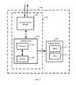
- FIG. 6is a schematic diagram of an overall communication architecture of the mechanical support system of FIG. 1 .
- a drivelinecouples the implanted blood pump 100 to the system controller 20 , which monitors system operation via various software applications.
- the blood pump 100itself also includes several software applications that are executable by the on board electronics 130 (e.g., processors) for various functions, such as to control radial levitation and/or drive of the rotor of the pump 100 during operation.
- the system controller 20may in turn be coupled to batteries 22 or a power module 30 that connect to an AC electrical outlet.
- the system controller 20may also include an emergency backup battery (EBB) to power the system (e.g., when the batteries 22 are depleted) and a membrane overlay, including bluetooth capabilities for wireless data communication.
- EBBemergency backup battery
- An external computer having a system monitor 32 that is configurable by an operator, such as clinician or patient,may further be coupled to the circulatory support system for configuring the system controller 20 , implanted blood pump 100 , and/or patient parameters, updating software on the system controller 20 and/or implanted blood pump 100 , monitoring system operation, and/or as a conduit for system inputs or outputs.
- the software applications of the blood pump 100can include, for example, an initial program loader (IPL), loader software, and/or application software.
- the IPLcan be configured to select and load one or several software applications corresponding, to one or several modes of operation of the blood pump 100 .
- these, one or several modes of operation of the blood pump 100can include an operation mode, a test mode, a fault mode, or the like.
- the selecting and loading of one or several software applications corresponding to one or several modes of operation of the blood pump 100can include, for example, selecting and loading one or several of the loader software and/or the application software.
- the IPLcan include information relating to one or several failsafe and/or fault protocols that can be used by the blood pump 100 . Some of these failsafe and/or fault protocols will be discussed at length below.
- the loader softwarecan, in some embodiments, be configured to direct the operation of the blood pump 100 during the loading of one or several software applications onto the blood pump 100 .
- These one or several software applicationscan include, for example, one or several application softwares, one or several IPL applications, or the like.
- the loader softwarecan prescribe one or several processes for updating and/or loading one or several software applications onto the blood pump 100 . These processes and associated failsafes will be discussed in greater details below.
- the application softwarecan include one or several parameters for directing the pumping operation of the blood pump 100 .
- the application softwarecan comprise one of a clinical application software which can be configured to control the operation of the blood pump 100 when implanted in a patient, and in some embodiments, the application software can comprise a production software that can be configured to control the operation of the blood pump 100 during production and/or testing of the blood pump 100 .
- these parameterscan specify a control or control regimen for the position and/or motion of the rotor 140 .
- these parameterscan specify the aspects of the levitation control and/or rotation control of the rotor 140 .
- the parameters of the application softwarecan specify, for example a desired performance of the blood pump 100 and/or one or several desired performance parameters, such as, for example, a desired pump speed, and desired pumped flow rate, a pulse generation, or the like. In some embodiments, these parameters can be actively used to control the operation of the blood pump 100 , and in some embodiments these parameters can be stored during normal operation of the blood pump 100 and used as part of one or several failsafe and/or fault protocols. In some embodiments, the parameters of the application software can specify the generation and/or collection of data from the blood pump 100 and/or interfacing of the blood pump 100 to other components of the mechanical circulatory support system 10 .
- the application softwarecan comprises a first application software containing parameters relating to the current operation of the blood pump, and in some embodiments, the application software can comprise a second application software containing parameters unrelated to the current operation of the blood pump 100 .
- the blood pump 100can comprise the second application software as a backup to the first application software.
- the first application softwarecan be identical to the second application software, and in some embodiments, the first application can be different than the second application software.
- FIG. 7is at schematic diagram illustrating one embodiment of the blood pump 100 .
- the blood pump 100includes electronics 130 and a rotary motor 200 , which rotary motor 200 call include the stator 120 and the rotor 140 .
- the electronics 130can include a control unit 202 that can control the operations of the blood pump 100 and can interact with other components of the mechanical circulatory support system 10 .
- the control unit 202can communicate with the rotary motor 200 and with the communications module 208 .
- the control unit 202 and electronics 130can be located in the same implantable housing 110 as the rotary motor 200 , and in some embodiments, the control unit and electronics can be located in a separate implantable housing than the blood pump housing 110 .
- the system controller 20can be located in an implantable housing, and the control unit 202 and electronics 130 can be co-located in that same implantable housing in a fully implantable transcutaneous energy transfer system.
- the control unit 202can, include a processor 204 .
- the processor 204can provide instructions to, and receive information from the other components of the blood pump 100 and/or from the other components of the mechanical circulatory support system 10 .
- the processor 204can act according to stored instructions, which stored instructions can be located in memory 206 associated with the processor 204 and/or in other components of the blood pump 100 and/or of the mechanical circulatory support system 10 .
- the processor 204can comprise a microprocessor, such as a microprocessor from Intel® or Advanced Micro Devices, Inc.®, or the like.
- the stored instructions directing the operation of the processor 204may be implemented by hardware, software, scripting languages, firmware, middleware, microcode, hardware description languages, and/or any combination thereof.
- the program code or code segments to perform the necessary tasksmay be stored in a machine readable medium such as a storage medium.
- a code segment or machine-executable instructionmay represent a procedure, a function, a subprogram, a program, a routine, a subroutine, a module, a software package, a script, a class, or any combination of instructions, data structures, and/or program statements.
- a code segmentmay be coupled to another code segment or a hardware circuit by passing and/or receiving information, data, arguments, parameters, and/or memory contents.
- Information, arguments, parameters, data, etc.may be passed, forwarded, or transmitted via any suitable means including memory sharing, message passing, token passing, network transmission, etc.
- the control unit 202includes a memory 206 .
- the memory 206is the storage medium containing the stored instructions.
- the memory 206may represent one or more memories for storing data, including read only memory (ROM), random access memory (RAM), magnetic RAM, core memory, magnetic disk storage mediums, optical storage mediums, flash memory devices and/or other machine readable mediums for storing information.
- the memory 206may be implemented within the processor 204 or external to the processor 204 .
- the memory 206can be any type of long term, short term, volatile, nonvolatile, or other storage medium and is not to be limited to any particular type of memory or number of memories, or type of media upon which memory is stored.
- the memory 206can include, for example, one or both of volatile and nonvolatile memory.
- the memory 206can include a volatile portion such as RAM memory, and a nonvolatile portion such as flash memory.
- the memory 206can be divided into one or several partitions. In one embodiment in which the memory 206 contains a plurality of software applications, the memory 206 can be divided into a plurality of partitions so as to be, for example, in a one to one relationship with the number of software applications in the plurality of software applications. In some embodiments, some or all of the software applications stored in the memory 206 can be stored in a unique one of the partitions in the memory 206 . In one embodiment in which the memory 206 comprises a volatile portion and a nonvolatile portion, the partitions can be created in one or both of the volatile portion and the nonvolatile portion. Specifically, in one embodiment in which the memory 206 comprises RAM and flash memory, the flash memory can be divided into a plurality of partitions. In some embodiments, the plurality of software applications can be stored in the plurality of partitions in the flash memory.
- the processor 204can send information and/or signals with and/or receive information and/or signals from the communications module 208 .
- the communications module 208can include features configured to send and receive information, including, for example, an antenna, a transmitter, receiver, or any other feature that can send and receive information.
- the communications module 208can communicate via a wired or wireless link with, for example, the system controller 20 and/or the rotary motor 200 .
- the communications module 208can communicate via cellular networks, WLAN networks, or any other wireless network.
- the blood pump 100can be configured to generate a signal in response to some or all communications received from in the system controller 20 , and/or to not generate a signal to the system controller 20 unless a signal from the system controller 20 has been first received by the blood pump 100 .
- FIG. 8is a flow-chart illustrating one embodiment of a process 220 for operation of the blood pump 100 .
- the process 220can be performed to start the pumping of the blood pump 100 , and can be performed using components of the blood pump 100 including, for example, the control unit 202 .
- the process 220begins, in some embodiments, at block 222 wherein the blood pump 100 is powered up.
- the powering up the blood pumped 100can include the receipt of power by the blood pump 100 from one of the batteries 22 and/or other power source.
- the process 220proceeds to block 224 wherein the IPL is run.
- the running of the IPLcan include, for example, retrieval of the IPL from the memory 206 and the execution of IPL instructions by the processor 204 .
- the process 220proceeds to block 226 wherein the IPL selects one or several software applications for control of the blood pump 100 .
- the one or several software applicationscan be selected from the memory 206 .
- the process 220proceeds to block 228 wherein the IPL determines the validity of the one or several selected software applications. In some embodiments, this can include the determination of the functionality of the one or several software applications and/or the detection of any faults and/or errors in, or caused one or several selected software applications.
- the process 220proceeds to block 210 wherein the IPL retrieves the one or sever selected software applications from the memory 206 and starts the one or several selected software applications.
- the IPLcan, for example, and as depicted in block 232 , copy a software application stored in one of the partitions of the memory 206 , such as, for example, a second partition in the flash memory, to the RAM and start the copied software application.
- the IPLcan, and as depicted in block 234 , copy a software application stored in one of the partitions of the memory, such as, for example, a third partition in the flash memory, to the RAM and start the copied software application.
- the starting of the software application stored in one of the second partition and the third partitioncan result in the starting of the blood pump 100 , the starting of the movement of the rotor 140 , and the starting of the associated pumping of blood.
- the IPLcan, as depicted in block 236 , start the loader software.
- the loader softwarecan be started as an early step in the update of the blood pump 100 .
- FIG. 9is a schematic illustration of one embodiment of memory 206 of the blood pump 100 .
- the memory 206 of the blood pumpcan include volatile memory, such as RAM 260 and non-volatile memory such as flash 202 .
- the flash 262can be divided into several partitions. In the embodiment depicted in FIG. 9 , the flash 262 is divided into partition 0 264 -A, partition 1 264 -B, partition 2 264 -C, partition 3 264 -D, partition 4 264 -E, partition 5 264 -F. As seen in FIG. 9 , some of the partitions 264 -A- 264 -F contain a software application.
- partition 0 264 -Acontains the IPL and loader software
- partition 1 264 -Bcontains a backup copy of the IPL and loader software
- partition 2 264 -C and partition 3 264 -Deach contain application software and application software information.
- partition 2 264 -C and partition 3 264 -Dcorrespond to the second and third memory partitions, respectively.
- partition 2 264 -C and partition 3 264 -Dare each divided into first and second portions.
- the first portion of partition 2 264 -Ccontains first application software 266 and the first portion of partition 3 264 -D contains second application software 268 .
- the second portion of partition 2 264 -Ccontains first application software information 270 and the second portion of partition 3 264 -D contains second application software information 272 .
- the application softwarein can include, a datum that can be used to identify/verify the application software, such as, for example, a hash or a checksum and information either absolutely or relatively identifying the time and/or date that the application software was loaded on the blood pump 100 .
- a datumthat can be used to identify/verify the application software, such as, for example, a hash or a checksum and information either absolutely or relatively identifying the time and/or date that the application software was loaded on the blood pump 100 .
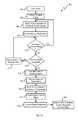
- FIG. 10is a flowchart illustrating one embodiment of a process 300 for operation of the blood pump 100 when communication with the system controller 20 is lost or interrupted.
- the process 300can be performed on the blood pump 100 and/or by components communicatively coupled to the blood pump 100 such as, for example, the electronics 130 and/or the control unit 202 .
- the process 300begins at block 302 wherein the blood pump 100 is started, and specifically, wherein the pumping of the blood pump 100 is initiated.
- the blood pump 100can be started according to the process 220 shown in FIG. 8 .
- the process 300proceeds to block 304 , wherein a control signal is received from the system controller 20 .
- the control signal received from the system controller 20can be used by the control unit 202 in the controlling of the position, motion, and/or performance of the rotor 140 of the blood pump 100 .
- the control signalcan be received by the control unit 202 of the blood pump 100 , and specifically, in some embodiments, can be received by the communications module 206 of the blood pump 100 .
- the process 300proceeds to block 306 , wherein the blood pump operation/performance is matched to the operation/performance specified by the control signal.
- thiscan include determining the current operation/performance of the blood pump 100 , comparing the current operation/performance of the blood pump 100 to the operation/performance specified by the control signal, and controlling components of the stator 120 to achieve the operation/performance specified by the control signal if the current operation/performance of the blood pump 100 differs from the operation/performance specified by the control signal.
- the matching of the pump operation/performance to the operation/performance specified in the control signalcan further include the generation and transmission of a message by the control unit 202 to the system controller 20 , which message can identify the current operation/performance of the blood pump 100 .
- the process 300proceeds to block 308 , wherein at least one back-up parameter is stored.
- the back-up parameterscan include one or several back-up parameters, and can be stored in the memory 206 of the blood pump 100 .
- the back-up parameterscan be stored in one of the partitions 264 -A- 264 -F of the flash memory.
- the one or several back up parameterscan be received as a component of the control signal, in some embodiments, the one or several back-up parameters can be created from data received from the control signal, and in some embodiments, the one or several back-up parameters can be received separate from the receipt of the control signal. The details of the creation of the one or several back-up parameters will be discussed at greater length below.
- the process 300proceeds to decision state 310 , wherein it is determined if additional control signals and/or communications from the system controller 20 have been received. In some embodiments, this can include receiving information from, for example, the communications module 208 relating to any received communications. If an additional communication and/or control signal has been received, then the process 300 returns to block 306 and proceeds as outlined above.
- the process 300proceeds to decision state 312 , wherein it is determined if the communication time has been exceeded.
- the communication timecan be, for example, an anticipated and/or desired frequency with which communications are expected from the system controller 20 .
- the communication timecan indicate that a communication is expected from the system controller 20 every ten seconds, every five seconds, every second, twice a second, five times a second, ten times a second, and/or at any other or intermediate frequency.
- the communication timecan be the maximum length of time that can pass without receiving a communication from the system controller 20 before an error is identified and/or an alarm is triggered, in one embodiment, for example, this amount of tune can be one minute, thirty seconds, ten seconds, five seconds, one second, 0.5 seconds, or any other or intermediate length of time.
- the properties, of the communication timecan be identified in communication time information stored in, for example, the memory 206 of the blood pump 100 .
- the communication time informationis retrieved from the memory, the length of time that has passed since the last received communication is determined, and the determined length of time that has passed since the last received communication is compared to the communication time, if the length of time that has passed since the last received communication is less than the communication time, then the process 300 proceeds to block 314 and waits until the end of the communication time. In some embodiments, the process 300 then proceeds to decision state 310 and proceeds as outlined above.
- the process 300proceeds to block 316 , wherein the loss or interruption of communication is indicated.
- the loss of communicationcan be indicated by triggering an error and/or an alarm.
- the loss of communicationcan be indicated by a value associated with the triggered error and/or alarm, and/or associated with the loss of communication. This value can be stored in the memory 206 , and in some embodiments, this value can be stored in the RAM.
- the process 300proceeds to block 318 , wherein one or several back-up parameters are retrieved.
- the one or several back-up parameterscan contain some or all of the parameters contained in the control signals received from the system controller 20 and that relate to the performance of the blood pump 100 including, for example, the speed, operational mode, or pulse parameter of the rotary motor 200 .
- the one or several back-up parameterscan be retrieved from the memory 206 such as, for example, the flash memory.
- the process 300proceeds to block 320 , wherein the wherein the blood pump operation/performance is matched to the operation/performance specified by the one or several back-up parameters.
- thiscan include determining the current operation/performance of the blood pump 100 , comparing the current operation/performance of the blood pump 100 to the operation/performance specified by the one or several back-up parameters, and controlling components of the stator 120 to achieve the operation/performance specified by the one or several back-up parameters, if the current operation/performance of the blood pump 100 differs from the operation/performance specified by the one or several back-up parameters.
- controlling components of the stator 120 to achieve the operation/performance specified by the one or several back-up parameterscan include generating one or several control signals that direct components of the stator to achieve the pump performance specified by the at least one back-up parameter.
- the process 300proceeds to block 322 , wherein a new control signal is received.
- the new control signalcan be received from the system controller 20 , and can be received when communication between the system controller 20 and the blood pump 100 is reestablished.
- the new control signalcan be received at any time.
- the time between the control signal received in block 304 and the new control signalcan be any time larger than the communication time.
- this time between the control signal received in block 304 and the new control signalcan be, for example, 1 second, 5 seconds, 10 seconds, 20 seconds, 30 seconds, 1 minute, 5 minutes, 10 minutes, 30 minutes, 1 hour, 1 day, 1 week, 1 month, 1 year, and/or any other or intermediate length of time.
- the receipt of the new control signalcan lead to the triggering of a return to normal status from the error and/or alarm state indicated in block 316 .
- a valuecan be associated with the restored normal state of operation, which value can be stored in the memory 206 , and in some embodiments, in the RAM.
- the process 300proceeds to block 324 , wherein the status response is provided.
- the status responsecan be a response indicative of the status of the blood pump 100 that can be provided by the blood pump 100 to the system controller 20 .
- the status responsecan include information indicative of the current operation of the blood pump 100 including, for example, a speed, a mode, or a pulse parameter.
- the process 300proceeds to block 326 , wherein the blood pump operation/performance is matched to the operation/performance specified by the new control signal.
- thiscan include determining the current operation/performance of the blood pump 100 , comparing the current operation/performance of the blood pump 100 to the operation/performance specified by the new control signal, and controlling components of the stator 120 to achieve the operation/performance specified by the new control signal if the current operation/performance of the blood pump 100 differs from the operation/performance specified by the new control signal.
- the matching of the blood pump operation/performance to the operation/performance specified in the new control signalcan further include the generation and transmission of a message by the control unit 202 to the system controller 20 , which message can identify the current operation performance of the blood pump 100 .
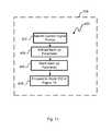
- FIG. 11is a flowchart illustrating one embodiment of process 400 for generating a back-up parameter.
- the process 400can be performed as part of block 308 shown in FIG. 10 .
- the process 400can be performed by the blood pump 100 and/or components thereof.
- the processbegins at block 402 , wherein control signal portions are identified.
- the control signalcan comprise one or several portions which can, in some embodiments, include unique information.
- the control signalcan include a first portion that can include information relating to a speed of the blood pump 100 , and a second portion that can include information relating to a mode of operation of the blood pump 100 and/or a pulse parameter of the blood pump 100 .
- the mode of operation of the blood pump 100can specify pulsatile and/or non-pulsatile operation of the blood pump 100 .
- the pulse parametercan specify one of a pulse duration, a systolic pressure, a diastolic pressure, and/or a pulse pressure.
- the process 400proceeds to block 404 wherein the back-up parameter is extracted from, for example, the control signal.
- the extraction of the back-up parametercan include the separation of one of the portions of the control signal from the other of the portions of the control signal.
- the back-up parametercan comprise the first portion of the control signal, which first portion includes information relating to the speed of the blood pump 100 .
- the process 400proceeds to block 406 , wherein the back-up parameter is stored.
- the back-up parametercan be stored in the memory 206 , including, for example, in the flash memory or in one of the partitions of the flash memory.
- the process 400proceeds to block 408 and continues with block 310 of FIG. 10 .
Landscapes
- Health & Medical Sciences (AREA)
- Heart & Thoracic Surgery (AREA)
- Engineering & Computer Science (AREA)
- Cardiology (AREA)
- Life Sciences & Earth Sciences (AREA)
- Anesthesiology (AREA)
- Biomedical Technology (AREA)
- Hematology (AREA)
- Mechanical Engineering (AREA)
- Animal Behavior & Ethology (AREA)
- General Health & Medical Sciences (AREA)
- Public Health (AREA)
- Veterinary Medicine (AREA)
- Medical Informatics (AREA)
- Vascular Medicine (AREA)
- External Artificial Organs (AREA)
Abstract
Description
Claims (27)
Priority Applications (1)
| Application Number | Priority Date | Filing Date | Title |
|---|---|---|---|
| US15/651,875US10500324B2 (en) | 2014-04-15 | 2017-07-17 | Systems for LVAD operation during communication losses |
Applications Claiming Priority (3)
| Application Number | Priority Date | Filing Date | Title |
|---|---|---|---|
| US201461979803P | 2014-04-15 | 2014-04-15 | |
| US14/687,817US9744280B2 (en) | 2014-04-15 | 2015-04-15 | Methods for LVAD operation during communication losses |
| US15/651,875US10500324B2 (en) | 2014-04-15 | 2017-07-17 | Systems for LVAD operation during communication losses |
Related Parent Applications (1)
| Application Number | Title | Priority Date | Filing Date |
|---|---|---|---|
| US14/687,817DivisionUS9744280B2 (en) | 2014-04-15 | 2015-04-15 | Methods for LVAD operation during communication losses |
Publications (2)
| Publication Number | Publication Date |
|---|---|
| US20170326283A1 US20170326283A1 (en) | 2017-11-16 |
| US10500324B2true US10500324B2 (en) | 2019-12-10 |
Family
ID=54264199
Family Applications (2)
| Application Number | Title | Priority Date | Filing Date |
|---|---|---|---|
| US14/687,817Active2035-05-06US9744280B2 (en) | 2014-04-15 | 2015-04-15 | Methods for LVAD operation during communication losses |
| US15/651,875Active2035-10-16US10500324B2 (en) | 2014-04-15 | 2017-07-17 | Systems for LVAD operation during communication losses |
Family Applications Before (1)
| Application Number | Title | Priority Date | Filing Date |
|---|---|---|---|
| US14/687,817Active2035-05-06US9744280B2 (en) | 2014-04-15 | 2015-04-15 | Methods for LVAD operation during communication losses |
Country Status (3)
| Country | Link |
|---|---|
| US (2) | US9744280B2 (en) |
| EP (1) | EP3131595B1 (en) |
| WO (1) | WO2015160992A1 (en) |
Cited By (1)
| Publication number | Priority date | Publication date | Assignee | Title |
|---|---|---|---|---|
| US11452860B2 (en) | 2020-07-31 | 2022-09-27 | Medtronic, Inc. | Power source selection for a fully implantable LVAD system |
Families Citing this family (19)
| Publication number | Priority date | Publication date | Assignee | Title |
|---|---|---|---|---|
| WO2010042011A1 (en)* | 2008-10-10 | 2010-04-15 | Milux Holding Sa | Heart help device, system, and method |
| US9744280B2 (en) | 2014-04-15 | 2017-08-29 | Tc1 Llc | Methods for LVAD operation during communication losses |
| WO2015160994A1 (en) | 2014-04-15 | 2015-10-22 | Thoratec Corporation | Methods and systems for upgrading ventricle assist devices |
| CN108367103B (en) | 2015-12-04 | 2021-06-25 | 奇德尼实验室公司 | Implantable renal replacement therapy |
| WO2018136592A2 (en) | 2017-01-18 | 2018-07-26 | Tc1 Llc | Systems and methods for transcutaneous power transfer using microneedles |
| CA3066361A1 (en) | 2017-06-07 | 2018-12-13 | Shifamed Holdings, Llc | Intravascular fluid movement devices, systems, and methods of use |
| US11110265B2 (en) | 2017-11-03 | 2021-09-07 | Heartware, Inc. | Updating a VAD system without stopping the pump |
| WO2019094963A1 (en) | 2017-11-13 | 2019-05-16 | Shifamed Holdings, Llc | Intravascular fluid movement devices, systems, and methods of use |
| CN112004563B (en) | 2018-02-01 | 2024-08-06 | 施菲姆德控股有限责任公司 | Intravascular blood pump and methods of use and manufacture |
| US12161857B2 (en) | 2018-07-31 | 2024-12-10 | Shifamed Holdings, Llc | Intravascular blood pumps and methods of use |
| WO2020073047A1 (en) | 2018-10-05 | 2020-04-09 | Shifamed Holdings, Llc | Intravascular blood pumps and methods of use |
| WO2021011473A1 (en) | 2019-07-12 | 2021-01-21 | Shifamed Holdings, Llc | Intravascular blood pumps and methods of manufacture and use |
| US11654275B2 (en) | 2019-07-22 | 2023-05-23 | Shifamed Holdings, Llc | Intravascular blood pumps with struts and methods of use and manufacture |
| WO2021062265A1 (en) | 2019-09-25 | 2021-04-01 | Shifamed Holdings, Llc | Intravascular blood pump systems and methods of use and control thereof |
| EP4501393A3 (en) | 2019-09-25 | 2025-04-09 | Shifamed Holdings, LLC | Catheter blood pumps and collapsible pump housings |
| US12121713B2 (en) | 2019-09-25 | 2024-10-22 | Shifamed Holdings, Llc | Catheter blood pumps and collapsible blood conduits |
| EP4072650A4 (en) | 2019-12-11 | 2024-01-10 | Shifamed Holdings, LLC | Descending aorta and vena cava blood pumps |
| WO2022093421A1 (en)* | 2020-10-29 | 2022-05-05 | Heartware, Inc. | Processes for vad controller exchange and software upgrade with uninterrupted circulatory support |
| CN117122811B (en)* | 2023-10-26 | 2024-01-02 | 苏州同心医疗科技股份有限公司 | Self-starting method applied to ventricular assist device system |
Citations (109)
| Publication number | Priority date | Publication date | Assignee | Title |
|---|---|---|---|---|
| EP0750921A2 (en) | 1995-06-28 | 1997-01-02 | Pacesetter, Inc. | Implantable cardiac stimulation device |
| US5695471A (en) | 1996-02-20 | 1997-12-09 | Kriton Medical, Inc. | Sealless rotary blood pump with passive magnetic radial bearings and blood immersed axial bearings |
| US5708346A (en) | 1994-01-10 | 1998-01-13 | Sulzer Electronics Ag | Method and control apparatus for controlling an AC-machine |
| US5725357A (en) | 1995-04-03 | 1998-03-10 | Ntn Corporation | Magnetically suspended type pump |
| US5735882A (en) | 1996-11-25 | 1998-04-07 | Sulzer Intermedics Inc. | Cardiac stimulator with backup-mode self-recovery |
| US5888242A (en) | 1996-11-01 | 1999-03-30 | Nimbus, Inc. | Speed control system for implanted blood pumps |
| US5947703A (en) | 1996-01-31 | 1999-09-07 | Ntn Corporation | Centrifugal blood pump assembly |
| US6053705A (en) | 1996-09-10 | 2000-04-25 | Sulzer Electronics Ag | Rotary pump and process to operate it |
| US6071093A (en) | 1996-10-18 | 2000-06-06 | Abiomed, Inc. | Bearingless blood pump and electronic drive system |
| US6100618A (en) | 1995-04-03 | 2000-08-08 | Sulzer Electronics Ag | Rotary machine with an electromagnetic rotary drive |
| US6116862A (en) | 1996-06-25 | 2000-09-12 | Medos Medizintechnik Gmbh | Blood pump |
| US6146325A (en) | 1999-06-03 | 2000-11-14 | Arrow International, Inc. | Ventricular assist device |
| US6186665B1 (en) | 1999-01-26 | 2001-02-13 | Nimbus, Inc. | Motor rotor bearing assembly for a blood pump |
| US6222290B1 (en) | 1998-08-24 | 2001-04-24 | Sulzer Electronics Ag | Sensor arrangement in an electromagnetic rotary drive and a method for the operation of a rotary drive of this kind |
| US6234772B1 (en) | 1999-04-28 | 2001-05-22 | Kriton Medical, Inc. | Rotary blood pump |
| US6249067B1 (en) | 1998-08-24 | 2001-06-19 | Sulzer Electronics Ag | Method and sensor arrangement for the determination of the radial position of a permanent magnetic rotor |
| US6264635B1 (en) | 1998-12-03 | 2001-07-24 | Kriton Medical, Inc. | Active magnetic bearing system for blood pump |
| US6278251B1 (en) | 1998-09-24 | 2001-08-21 | Sulzer Electronics Ag | Permanent magnetically excited electrical rotary drive |
| US6351048B1 (en) | 1999-06-22 | 2002-02-26 | Levitronix Llc | Electrical rotary drive |
| US6468041B2 (en) | 2000-05-25 | 2002-10-22 | Ntn Corporation | Magnetically levitated apparatus |
| US20030069465A1 (en) | 1997-10-02 | 2003-04-10 | Micromed Technology, Inc. | Implantable pump system |
| US6575717B2 (en) | 1999-12-27 | 2003-06-10 | Ntn Corporation | Magnetically levitated pump |
| US6589030B2 (en) | 2000-06-20 | 2003-07-08 | Ntn Corporation | Magnetically levitated pump apparatus |
| US6626644B2 (en) | 2000-10-30 | 2003-09-30 | Ntn Corporation | Magnetically levitated pump and controlling circuit |
| US6634224B1 (en) | 1998-07-10 | 2003-10-21 | Levitronix Llc | Method for the determination of the pressure in and/or of the through-flow through a pump |
| US6688861B2 (en) | 1996-02-20 | 2004-02-10 | Heartware, Inc. | Sealless rotary blood pump |
| US6707200B2 (en) | 2000-11-14 | 2004-03-16 | Airex Corporation | Integrated magnetic bearing |
| US6817836B2 (en) | 2002-09-10 | 2004-11-16 | Miwatec Incorporated | Methods and apparatus for controlling a continuous flow rotary blood pump |
| US20050071001A1 (en) | 2003-09-30 | 2005-03-31 | Robert Jarvik | Artificial heart power and control system |
| US6879074B2 (en) | 2000-07-16 | 2005-04-12 | Levitronix Llc | Stator field providing torque and levitation |
| US6949066B2 (en) | 2002-08-21 | 2005-09-27 | World Heart Corporation | Rotary blood pump diagnostics and cardiac output controller |
| US6991595B2 (en) | 2002-04-19 | 2006-01-31 | Thoratec Corporation | Adaptive speed control for blood pump |
| US7112903B1 (en) | 1997-08-25 | 2006-09-26 | Levitronix Llc | Magnetically journalled rotational arrangement including a rotor for generating a unipolar bias magnetic flux |
| US7138776B1 (en) | 1999-07-08 | 2006-11-21 | Heartware, Inc. | Method and apparatus for controlling brushless DC motors in implantable medical devices |
| US7150711B2 (en) | 2001-04-30 | 2006-12-19 | Berlin Heart Ag | Method for controlling an assist pump for fluid delivery systems with pulsatile pressure |
| US20070078293A1 (en) | 2005-10-05 | 2007-04-05 | Shambaugh Charles R Jr | Impeller for a rotary ventricular assist device |
| US7229474B2 (en) | 2001-04-30 | 2007-06-12 | Berlin Heart Ag | Method for controlling the position of a permanent magnetically supported rotating component |
| US20070142696A1 (en) | 2005-12-08 | 2007-06-21 | Ventrassist Pty Ltd | Implantable medical devices |
| US7239098B2 (en) | 2002-06-13 | 2007-07-03 | Halliburton Energy Services, Inc. | Digital adaptive sensorless commutational drive controller for a brushless DC motor |
| US7284956B2 (en) | 2002-09-10 | 2007-10-23 | Miwatec Co., Ltd. | Methods and apparatus for controlling a continuous flow rotary blood pump |
| US20080021394A1 (en) | 2006-01-13 | 2008-01-24 | Larose Jeffrey A | Stabilizing drive for contactless rotary blood pump impeller |
| US7462019B1 (en) | 1998-04-22 | 2008-12-09 | Allarie Paul E | Implantable centrifugal blood pump with hybrid magnetic bearings |
| US7497116B2 (en) | 2004-04-15 | 2009-03-03 | Sun Medical Technology Research Corporation | Flow rate estimation method of blood pump |
| US7511443B2 (en) | 2002-09-26 | 2009-03-31 | Barrett Technology, Inc. | Ultra-compact, high-performance motor controller and method of using same |
| US20090203957A1 (en) | 2008-02-08 | 2009-08-13 | Larose Jeffrey A | Ventricular assist device for intraventricular placement |
| US7591777B2 (en) | 2004-05-25 | 2009-09-22 | Heartware Inc. | Sensorless flow estimation for implanted ventricle assist device |
| US7645225B2 (en) | 2000-03-27 | 2010-01-12 | Alexander Medvedev | Chronic performance control system for rotodynamic blood pumps |
| US7699586B2 (en) | 2004-12-03 | 2010-04-20 | Heartware, Inc. | Wide blade, axial flow pump |
| US7699588B2 (en) | 2003-07-04 | 2010-04-20 | Jostra Ag | Centrifugal pump |
| US20100130809A1 (en) | 2007-04-05 | 2010-05-27 | Micromed Technology, Inc. | Blood pump system |
| US20100152526A1 (en)* | 1994-04-15 | 2010-06-17 | Pacella John J | Blood pump device and method of producing |
| US20100241223A1 (en) | 2007-06-06 | 2010-09-23 | WorldHeart, Inc. | Wearable vad controller with reserve battery |
| US20100327687A1 (en) | 2009-06-24 | 2010-12-30 | Victor Iannello | Systems, Devices, and/or Methods for Managing Magnetic Bearings |
| US20110066211A1 (en) | 2001-12-19 | 2011-03-17 | Von Arx Jeffrey A | Implantable medical device with two or more telemetry systems |
| US20110071337A1 (en) | 2008-03-26 | 2011-03-24 | Cardio Assist Ltd. | Heart assist device |
| US7951062B2 (en) | 2002-01-07 | 2011-05-31 | Micromed Technology, Inc. | Blood pump system and method of operation |
| US20110160518A1 (en)* | 2000-09-13 | 2011-06-30 | Cardiacassist, Inc. | Method and System for Closed Chest Blood Flow Support |
| US20110237863A1 (en) | 2008-09-26 | 2011-09-29 | WorldHeart, Inc. | Magnetically-levitated blood pump with optimization method enabling miniaturization |
| US20110313237A1 (en) | 2008-10-28 | 2011-12-22 | Hi-Lex Corporation | Medical device or instrument having porous structure |
| US20120022645A1 (en) | 2010-07-22 | 2012-01-26 | Thoratec Corporation | Controlling implanted blood pumps |
| US20120046514A1 (en) | 2010-08-20 | 2012-02-23 | Kevin Bourque | Implantable blood pump |
| US8152493B2 (en) | 2007-04-30 | 2012-04-10 | Hearthware Inc. | Centrifugal rotary blood pump with impeller having a hydrodynamic thrust bearing surface |
| US8157720B2 (en) | 2006-01-27 | 2012-04-17 | Circulite, Inc. | Heart assist system |
| US20120095281A1 (en) | 2010-10-13 | 2012-04-19 | Reichenbach Steven H | Pumping blood |
| US20120226097A1 (en) | 2005-06-06 | 2012-09-06 | Smith William A | Blood pump |
| US20120245681A1 (en) | 2011-01-21 | 2012-09-27 | Fernando Casas | Flow estimation in a blood pump |
| US8303482B2 (en) | 2004-09-07 | 2012-11-06 | Micromed | Method and system for physiologic control of a blood pump |
| US8323174B2 (en) | 2010-10-22 | 2012-12-04 | Nupulse, Inc. | Skin interface for ventricular assist device |
| US8382830B2 (en) | 2007-06-06 | 2013-02-26 | World Heart Corporation | Implantable VAD with replaceable percutaneous cable |
| US20130096364A1 (en) | 2011-10-13 | 2013-04-18 | Steven H. Reichenbach | Pump and method for mixed flow blood pumping |
| US20130121821A1 (en) | 2010-07-12 | 2013-05-16 | Terumo Kabushiki Kaisha | Centrifugal pump apparatus |
| US20130127253A1 (en) | 2011-11-21 | 2013-05-23 | Joseph Stark | Transcutaneous power transmission utilizing non-planar resonators |
| US8449444B2 (en) | 2009-02-27 | 2013-05-28 | Thoratec Corporation | Blood flow meter |
| US20130170970A1 (en) | 2010-09-14 | 2013-07-04 | Terumo Kabushiki Kaisha | Centrifugal pump apparatus |
| US8506471B2 (en) | 2010-09-24 | 2013-08-13 | Thoratec Corporation | Generating artificial pulse |
| US8517699B2 (en) | 2008-12-16 | 2013-08-27 | Cleveland Clinic Foundation | Centrifugal pump with offset volute |
| US20130225909A1 (en) | 2012-02-27 | 2013-08-29 | Terumo Kabushiki Kaisha | Quick-Connect Outflow Tube for Ventricular Assist Device |
| US8551070B2 (en) | 2007-09-07 | 2013-10-08 | Asante Solutions, Inc. | User profile backup system for an infusion pump device |
| US8556795B2 (en) | 2010-11-23 | 2013-10-15 | Minnetronix Inc. | Portable controller with integral power source for mechanical circulation support systems |
| US8562508B2 (en) | 2009-12-30 | 2013-10-22 | Thoratec Corporation | Mobility-enhancing blood pump system |
| US20130314047A1 (en) | 2012-05-24 | 2013-11-28 | Heartware, Inc. | Low-power battery pack with safety system |
| US8597350B2 (en) | 2010-12-09 | 2013-12-03 | Heartware, Inc. | Controller and power source for implantable blood pump |
| US20130331934A1 (en) | 2012-06-08 | 2013-12-12 | Cameron International Corporation | Artificial heart system |
| US20130338559A1 (en)* | 2010-02-17 | 2013-12-19 | Novita Therapeutics, Llc | Blood pump systems and methods |
| US20130345804A1 (en) | 2008-03-25 | 2013-12-26 | Sun Medical Technology Research Corporation | Auxiliary artificial heart pump drive device and auxiliary artificial heart system |
| US8628460B2 (en) | 2009-09-21 | 2014-01-14 | Heartware, Inc. | Hard-wired implanted controller system |
| US8652024B1 (en) | 2013-01-23 | 2014-02-18 | Thoratec Corporation | Sterilizable cable system for implantable blood pump |
| US8657733B2 (en) | 2005-11-04 | 2014-02-25 | Thoratec Corporation | Control systems for rotary blood pumps |
| US20140100413A1 (en) | 2011-01-21 | 2014-04-10 | Heartware, Inc. | Suction detection on an axial blood pump using bemf data |
| US8764621B2 (en) | 2011-07-11 | 2014-07-01 | Vascor, Inc. | Transcutaneous power transmission and communication for implanted heart assist and other devices |
| US20140194985A1 (en) | 2013-01-04 | 2014-07-10 | Heartware, Inc. | Controller and power source for implantable blood pump |
| US20140275723A1 (en) | 2013-03-14 | 2014-09-18 | Circulite, Inc. | Magnetically levitated and driven blood pump and method for using the same |
| US20140296615A1 (en)* | 2011-08-17 | 2014-10-02 | Novita Therapeutics, Llc | Blood pump systems and methods |
| US20140303426A1 (en) | 2013-04-05 | 2014-10-09 | Circulite, Inc. | Implantable blood pump, blood pump system, and method for data transfer in a blood pump system |
| US8870739B2 (en) | 2010-08-06 | 2014-10-28 | Heartware, Inc. | Conduit device for use with a ventricular assist device |
| US20140357937A1 (en) | 2013-06-04 | 2014-12-04 | Heartware, Inc. | Axial flow pump pressure algorithm |
| US20150051438A1 (en) | 2013-08-14 | 2015-02-19 | Heartware, Inc. | Impeller for axial flow pump |
| US20150209498A1 (en)* | 2010-02-17 | 2015-07-30 | F. Nicholas Franano | Blood pump systems and methods |
| US20150290378A1 (en) | 2014-04-15 | 2015-10-15 | Thoratec Corporation | Methods and systems for lvad operation during communication losses |
| US20150290376A1 (en)* | 2014-04-15 | 2015-10-15 | Thoratec Corporation | Methods and systems for upgrading ventricle assist devices |
| US20150328384A1 (en)* | 2008-06-11 | 2015-11-19 | Sun Medical Technology Research Corporation | Artificial heart control device, artificial heart system and artificial heart control method |
| US20160015883A1 (en)* | 2013-04-01 | 2016-01-21 | Terumo Kabushiki Kaisha | Circulation apparatus and method for controlling same |
| US20160220748A1 (en)* | 2013-09-12 | 2016-08-04 | Gambro Lundia Ab | Apparatus for extracorporeal treatment of blood and method of control of a blood-warming device in an extracorporeal blood treatment apparatus |
| US20160228631A1 (en)* | 2013-12-23 | 2016-08-11 | Fresenius Medical Care Holdings, Inc. | Automatic Detection And Adjustment Of A Pressure Pod Diaphragm |
| US20160271317A1 (en)* | 2007-02-09 | 2016-09-22 | Baxter International Inc | Blood treatment and electrical blood leak detection device therefore |
| US20180055989A1 (en)* | 2009-12-28 | 2018-03-01 | Gambro Lundia Ab | Controlling an apparatus for fluid transfer to and/or from a subject |
| US20180147333A1 (en)* | 2016-11-30 | 2018-05-31 | Heartware, Inc. | Patient behavior sensitive controller |
| US20180256798A1 (en)* | 2016-04-11 | 2018-09-13 | CorWave SA | Implantable pump system having an undulating membrane |
| US20190184079A1 (en)* | 2015-02-12 | 2019-06-20 | Tc1 Llc | System and method for controlling the position of a levitated rotor |
- 2015
- 2015-04-15USUS14/687,817patent/US9744280B2/enactiveActive
- 2015-04-15EPEP15779178.1Apatent/EP3131595B1/enactiveActive
- 2015-04-15WOPCT/US2015/026027patent/WO2015160992A1/enactiveApplication Filing
- 2017
- 2017-07-17USUS15/651,875patent/US10500324B2/enactiveActive
Patent Citations (129)
| Publication number | Priority date | Publication date | Assignee | Title |
|---|---|---|---|---|
| US5708346A (en) | 1994-01-10 | 1998-01-13 | Sulzer Electronics Ag | Method and control apparatus for controlling an AC-machine |
| US20100152526A1 (en)* | 1994-04-15 | 2010-06-17 | Pacella John J | Blood pump device and method of producing |
| US6100618A (en) | 1995-04-03 | 2000-08-08 | Sulzer Electronics Ag | Rotary machine with an electromagnetic rotary drive |
| US5725357A (en) | 1995-04-03 | 1998-03-10 | Ntn Corporation | Magnetically suspended type pump |
| EP0750921A2 (en) | 1995-06-28 | 1997-01-02 | Pacesetter, Inc. | Implantable cardiac stimulation device |
| US5947703A (en) | 1996-01-31 | 1999-09-07 | Ntn Corporation | Centrifugal blood pump assembly |
| US5695471A (en) | 1996-02-20 | 1997-12-09 | Kriton Medical, Inc. | Sealless rotary blood pump with passive magnetic radial bearings and blood immersed axial bearings |
| US6688861B2 (en) | 1996-02-20 | 2004-02-10 | Heartware, Inc. | Sealless rotary blood pump |
| US6116862A (en) | 1996-06-25 | 2000-09-12 | Medos Medizintechnik Gmbh | Blood pump |
| US6053705A (en) | 1996-09-10 | 2000-04-25 | Sulzer Electronics Ag | Rotary pump and process to operate it |
| US6071093A (en) | 1996-10-18 | 2000-06-06 | Abiomed, Inc. | Bearingless blood pump and electronic drive system |
| US5888242A (en) | 1996-11-01 | 1999-03-30 | Nimbus, Inc. | Speed control system for implanted blood pumps |
| US5735882A (en) | 1996-11-25 | 1998-04-07 | Sulzer Intermedics Inc. | Cardiac stimulator with backup-mode self-recovery |
| US7112903B1 (en) | 1997-08-25 | 2006-09-26 | Levitronix Llc | Magnetically journalled rotational arrangement including a rotor for generating a unipolar bias magnetic flux |
| US20030069465A1 (en) | 1997-10-02 | 2003-04-10 | Micromed Technology, Inc. | Implantable pump system |
| US6652447B2 (en) | 1997-10-02 | 2003-11-25 | Micromed Technology, Inc. | Method of controlling an implantable pump system |
| US6605032B2 (en) | 1997-10-02 | 2003-08-12 | Micromed Technology, Inc. | Implantable pump system |
| US7462019B1 (en) | 1998-04-22 | 2008-12-09 | Allarie Paul E | Implantable centrifugal blood pump with hybrid magnetic bearings |
| US6634224B1 (en) | 1998-07-10 | 2003-10-21 | Levitronix Llc | Method for the determination of the pressure in and/or of the through-flow through a pump |
| US6222290B1 (en) | 1998-08-24 | 2001-04-24 | Sulzer Electronics Ag | Sensor arrangement in an electromagnetic rotary drive and a method for the operation of a rotary drive of this kind |
| US6249067B1 (en) | 1998-08-24 | 2001-06-19 | Sulzer Electronics Ag | Method and sensor arrangement for the determination of the radial position of a permanent magnetic rotor |
| US6355998B1 (en) | 1998-08-24 | 2002-03-12 | Levitronix Llc | Sensor arrangement in an electromagnetic rotary drive and a method for the operation of a rotary drive of this kind |
| US6278251B1 (en) | 1998-09-24 | 2001-08-21 | Sulzer Electronics Ag | Permanent magnetically excited electrical rotary drive |
| US6264635B1 (en) | 1998-12-03 | 2001-07-24 | Kriton Medical, Inc. | Active magnetic bearing system for blood pump |
| US6186665B1 (en) | 1999-01-26 | 2001-02-13 | Nimbus, Inc. | Motor rotor bearing assembly for a blood pump |
| US6234772B1 (en) | 1999-04-28 | 2001-05-22 | Kriton Medical, Inc. | Rotary blood pump |
| US6146325A (en) | 1999-06-03 | 2000-11-14 | Arrow International, Inc. | Ventricular assist device |
| US6351048B1 (en) | 1999-06-22 | 2002-02-26 | Levitronix Llc | Electrical rotary drive |
| US7138776B1 (en) | 1999-07-08 | 2006-11-21 | Heartware, Inc. | Method and apparatus for controlling brushless DC motors in implantable medical devices |
| US6575717B2 (en) | 1999-12-27 | 2003-06-10 | Ntn Corporation | Magnetically levitated pump |
| US7645225B2 (en) | 2000-03-27 | 2010-01-12 | Alexander Medvedev | Chronic performance control system for rotodynamic blood pumps |
| US6468041B2 (en) | 2000-05-25 | 2002-10-22 | Ntn Corporation | Magnetically levitated apparatus |
| US6589030B2 (en) | 2000-06-20 | 2003-07-08 | Ntn Corporation | Magnetically levitated pump apparatus |
| US6879074B2 (en) | 2000-07-16 | 2005-04-12 | Levitronix Llc | Stator field providing torque and levitation |
| US20110160518A1 (en)* | 2000-09-13 | 2011-06-30 | Cardiacassist, Inc. | Method and System for Closed Chest Blood Flow Support |
| US6626644B2 (en) | 2000-10-30 | 2003-09-30 | Ntn Corporation | Magnetically levitated pump and controlling circuit |
| US6707200B2 (en) | 2000-11-14 | 2004-03-16 | Airex Corporation | Integrated magnetic bearing |
| US7229474B2 (en) | 2001-04-30 | 2007-06-12 | Berlin Heart Ag | Method for controlling the position of a permanent magnetically supported rotating component |
| US7150711B2 (en) | 2001-04-30 | 2006-12-19 | Berlin Heart Ag | Method for controlling an assist pump for fluid delivery systems with pulsatile pressure |
| US20110066211A1 (en) | 2001-12-19 | 2011-03-17 | Von Arx Jeffrey A | Implantable medical device with two or more telemetry systems |
| US7951062B2 (en) | 2002-01-07 | 2011-05-31 | Micromed Technology, Inc. | Blood pump system and method of operation |
| US6991595B2 (en) | 2002-04-19 | 2006-01-31 | Thoratec Corporation | Adaptive speed control for blood pump |
| US7239098B2 (en) | 2002-06-13 | 2007-07-03 | Halliburton Energy Services, Inc. | Digital adaptive sensorless commutational drive controller for a brushless DC motor |
| US6949066B2 (en) | 2002-08-21 | 2005-09-27 | World Heart Corporation | Rotary blood pump diagnostics and cardiac output controller |
| US6817836B2 (en) | 2002-09-10 | 2004-11-16 | Miwatec Incorporated | Methods and apparatus for controlling a continuous flow rotary blood pump |
| US7284956B2 (en) | 2002-09-10 | 2007-10-23 | Miwatec Co., Ltd. | Methods and apparatus for controlling a continuous flow rotary blood pump |
| US7511443B2 (en) | 2002-09-26 | 2009-03-31 | Barrett Technology, Inc. | Ultra-compact, high-performance motor controller and method of using same |
| US7854631B2 (en) | 2002-09-26 | 2010-12-21 | Barrett Technology, Inc. | Ultra-compact, high-performance motor controller |
| US7699588B2 (en) | 2003-07-04 | 2010-04-20 | Jostra Ag | Centrifugal pump |
| US20050071001A1 (en) | 2003-09-30 | 2005-03-31 | Robert Jarvik | Artificial heart power and control system |
| US7861582B2 (en) | 2004-04-15 | 2011-01-04 | Sun Medical Technology Research Corporation | Flow rate estimation method of blood pump |
| US7497116B2 (en) | 2004-04-15 | 2009-03-03 | Sun Medical Technology Research Corporation | Flow rate estimation method of blood pump |
| US8506470B2 (en) | 2004-05-25 | 2013-08-13 | Heartware, Inc. | Sensorless flow estimation for implanted ventricle assist device |
| US7591777B2 (en) | 2004-05-25 | 2009-09-22 | Heartware Inc. | Sensorless flow estimation for implanted ventricle assist device |
| US7887479B2 (en) | 2004-05-25 | 2011-02-15 | Heartware, Inc. | Sensorless flow estimation for implanted ventricle assist device |
| US8303482B2 (en) | 2004-09-07 | 2012-11-06 | Micromed | Method and system for physiologic control of a blood pump |
| US7699586B2 (en) | 2004-12-03 | 2010-04-20 | Heartware, Inc. | Wide blade, axial flow pump |
| US8668473B2 (en) | 2004-12-03 | 2014-03-11 | Heartware, Inc. | Axial flow pump with multi-grooved rotor |
| US8007254B2 (en) | 2004-12-03 | 2011-08-30 | Heartware, Inc. | Axial flow pump with multi-grooved rotor |
| US20120226097A1 (en) | 2005-06-06 | 2012-09-06 | Smith William A | Blood pump |
| US20070078293A1 (en) | 2005-10-05 | 2007-04-05 | Shambaugh Charles R Jr | Impeller for a rotary ventricular assist device |
| US8657733B2 (en) | 2005-11-04 | 2014-02-25 | Thoratec Corporation | Control systems for rotary blood pumps |
| US20070142696A1 (en) | 2005-12-08 | 2007-06-21 | Ventrassist Pty Ltd | Implantable medical devices |
| US7976271B2 (en) | 2006-01-13 | 2011-07-12 | Heartware, Inc. | Stabilizing drive for contactless rotary blood pump impeller |
| US7997854B2 (en) | 2006-01-13 | 2011-08-16 | Heartware, Inc. | Shrouded thrust bearings |
| US20080021394A1 (en) | 2006-01-13 | 2008-01-24 | Larose Jeffrey A | Stabilizing drive for contactless rotary blood pump impeller |
| US8157720B2 (en) | 2006-01-27 | 2012-04-17 | Circulite, Inc. | Heart assist system |
| US20160271317A1 (en)* | 2007-02-09 | 2016-09-22 | Baxter International Inc | Blood treatment and electrical blood leak detection device therefore |
| US20100130809A1 (en) | 2007-04-05 | 2010-05-27 | Micromed Technology, Inc. | Blood pump system |
| US8152493B2 (en) | 2007-04-30 | 2012-04-10 | Hearthware Inc. | Centrifugal rotary blood pump with impeller having a hydrodynamic thrust bearing surface |
| US8382830B2 (en) | 2007-06-06 | 2013-02-26 | World Heart Corporation | Implantable VAD with replaceable percutaneous cable |
| US20100241223A1 (en) | 2007-06-06 | 2010-09-23 | WorldHeart, Inc. | Wearable vad controller with reserve battery |
| US8551070B2 (en) | 2007-09-07 | 2013-10-08 | Asante Solutions, Inc. | User profile backup system for an infusion pump device |
| US20090203957A1 (en) | 2008-02-08 | 2009-08-13 | Larose Jeffrey A | Ventricular assist device for intraventricular placement |
| US20130345804A1 (en) | 2008-03-25 | 2013-12-26 | Sun Medical Technology Research Corporation | Auxiliary artificial heart pump drive device and auxiliary artificial heart system |
| US20110071337A1 (en) | 2008-03-26 | 2011-03-24 | Cardio Assist Ltd. | Heart assist device |
| US20150328384A1 (en)* | 2008-06-11 | 2015-11-19 | Sun Medical Technology Research Corporation | Artificial heart control device, artificial heart system and artificial heart control method |
| US20110237863A1 (en) | 2008-09-26 | 2011-09-29 | WorldHeart, Inc. | Magnetically-levitated blood pump with optimization method enabling miniaturization |
| US20110313237A1 (en) | 2008-10-28 | 2011-12-22 | Hi-Lex Corporation | Medical device or instrument having porous structure |
| US8517699B2 (en) | 2008-12-16 | 2013-08-27 | Cleveland Clinic Foundation | Centrifugal pump with offset volute |
| US8449444B2 (en) | 2009-02-27 | 2013-05-28 | Thoratec Corporation | Blood flow meter |
| US20100327687A1 (en) | 2009-06-24 | 2010-12-30 | Victor Iannello | Systems, Devices, and/or Methods for Managing Magnetic Bearings |
| US8628460B2 (en) | 2009-09-21 | 2014-01-14 | Heartware, Inc. | Hard-wired implanted controller system |
| US20180055989A1 (en)* | 2009-12-28 | 2018-03-01 | Gambro Lundia Ab | Controlling an apparatus for fluid transfer to and/or from a subject |
| US8562508B2 (en) | 2009-12-30 | 2013-10-22 | Thoratec Corporation | Mobility-enhancing blood pump system |
| US20150209498A1 (en)* | 2010-02-17 | 2015-07-30 | F. Nicholas Franano | Blood pump systems and methods |
| US20130338559A1 (en)* | 2010-02-17 | 2013-12-19 | Novita Therapeutics, Llc | Blood pump systems and methods |
| US20130121821A1 (en) | 2010-07-12 | 2013-05-16 | Terumo Kabushiki Kaisha | Centrifugal pump apparatus |
| US20120022645A1 (en) | 2010-07-22 | 2012-01-26 | Thoratec Corporation | Controlling implanted blood pumps |
| US8870739B2 (en) | 2010-08-06 | 2014-10-28 | Heartware, Inc. | Conduit device for use with a ventricular assist device |
| US20120046514A1 (en) | 2010-08-20 | 2012-02-23 | Kevin Bourque | Implantable blood pump |
| US20130170970A1 (en) | 2010-09-14 | 2013-07-04 | Terumo Kabushiki Kaisha | Centrifugal pump apparatus |
| US8506471B2 (en) | 2010-09-24 | 2013-08-13 | Thoratec Corporation | Generating artificial pulse |
| US20120095281A1 (en) | 2010-10-13 | 2012-04-19 | Reichenbach Steven H | Pumping blood |
| US8323174B2 (en) | 2010-10-22 | 2012-12-04 | Nupulse, Inc. | Skin interface for ventricular assist device |
| US8956275B2 (en) | 2010-11-23 | 2015-02-17 | Minnetronix Inc. | Portable controller with integral power source for mechanical circulation support systems |
| US8556795B2 (en) | 2010-11-23 | 2013-10-15 | Minnetronix Inc. | Portable controller with integral power source for mechanical circulation support systems |
| US8597350B2 (en) | 2010-12-09 | 2013-12-03 | Heartware, Inc. | Controller and power source for implantable blood pump |
| US20140100413A1 (en) | 2011-01-21 | 2014-04-10 | Heartware, Inc. | Suction detection on an axial blood pump using bemf data |
| US20120245681A1 (en) | 2011-01-21 | 2012-09-27 | Fernando Casas | Flow estimation in a blood pump |
| US8764621B2 (en) | 2011-07-11 | 2014-07-01 | Vascor, Inc. | Transcutaneous power transmission and communication for implanted heart assist and other devices |
| US20140296615A1 (en)* | 2011-08-17 | 2014-10-02 | Novita Therapeutics, Llc | Blood pump systems and methods |
| US20130096364A1 (en) | 2011-10-13 | 2013-04-18 | Steven H. Reichenbach | Pump and method for mixed flow blood pumping |
| US20130127253A1 (en) | 2011-11-21 | 2013-05-23 | Joseph Stark | Transcutaneous power transmission utilizing non-planar resonators |
| US20130225909A1 (en) | 2012-02-27 | 2013-08-29 | Terumo Kabushiki Kaisha | Quick-Connect Outflow Tube for Ventricular Assist Device |
| US20130314047A1 (en) | 2012-05-24 | 2013-11-28 | Heartware, Inc. | Low-power battery pack with safety system |
| US20130331934A1 (en) | 2012-06-08 | 2013-12-12 | Cameron International Corporation | Artificial heart system |
| US20140194985A1 (en) | 2013-01-04 | 2014-07-10 | Heartware, Inc. | Controller and power source for implantable blood pump |
| US8652024B1 (en) | 2013-01-23 | 2014-02-18 | Thoratec Corporation | Sterilizable cable system for implantable blood pump |
| US8882477B2 (en) | 2013-03-14 | 2014-11-11 | Circulite, Inc. | Magnetically levitated and driven blood pump and method for using the same |
| US20140275723A1 (en) | 2013-03-14 | 2014-09-18 | Circulite, Inc. | Magnetically levitated and driven blood pump and method for using the same |
| US20160015883A1 (en)* | 2013-04-01 | 2016-01-21 | Terumo Kabushiki Kaisha | Circulation apparatus and method for controlling same |
| US20140303426A1 (en) | 2013-04-05 | 2014-10-09 | Circulite, Inc. | Implantable blood pump, blood pump system, and method for data transfer in a blood pump system |
| US20140357937A1 (en) | 2013-06-04 | 2014-12-04 | Heartware, Inc. | Axial flow pump pressure algorithm |
| US20150051438A1 (en) | 2013-08-14 | 2015-02-19 | Heartware, Inc. | Impeller for axial flow pump |
| US20160220748A1 (en)* | 2013-09-12 | 2016-08-04 | Gambro Lundia Ab | Apparatus for extracorporeal treatment of blood and method of control of a blood-warming device in an extracorporeal blood treatment apparatus |
| US20160228631A1 (en)* | 2013-12-23 | 2016-08-11 | Fresenius Medical Care Holdings, Inc. | Automatic Detection And Adjustment Of A Pressure Pod Diaphragm |
| US20150290376A1 (en)* | 2014-04-15 | 2015-10-15 | Thoratec Corporation | Methods and systems for upgrading ventricle assist devices |
| US9629948B2 (en) | 2014-04-15 | 2017-04-25 | Tc1 Llc | Methods for upgrading ventricle assist devices |
| US20170173239A1 (en) | 2014-04-15 | 2017-06-22 | Tc1 Llc | Systems for upgrading ventricle assist devices |
| US9744280B2 (en) | 2014-04-15 | 2017-08-29 | Tc1 Llc | Methods for LVAD operation during communication losses |
| US9789237B2 (en) | 2014-04-15 | 2017-10-17 | Tc1 Llc | Systems for upgrading ventricle assist devices |
| US20180001006A1 (en)* | 2014-04-15 | 2018-01-04 | Tc1 Llc | Systems for upgrading ventricle assist devices |
| US20150290378A1 (en) | 2014-04-15 | 2015-10-15 | Thoratec Corporation | Methods and systems for lvad operation during communication losses |
| US9937284B2 (en) | 2014-04-15 | 2018-04-10 | Tc1 Llc | Systems for upgrading ventricle assist devices |
| US20180256795A1 (en)* | 2014-04-15 | 2018-09-13 | Tc1 Llc | Methods and systems for upgrading ventricle assist devices |
| US20190184079A1 (en)* | 2015-02-12 | 2019-06-20 | Tc1 Llc | System and method for controlling the position of a levitated rotor |
| US20180256798A1 (en)* | 2016-04-11 | 2018-09-13 | CorWave SA | Implantable pump system having an undulating membrane |
| US20180147333A1 (en)* | 2016-11-30 | 2018-05-31 | Heartware, Inc. | Patient behavior sensitive controller |
Cited By (1)
| Publication number | Priority date | Publication date | Assignee | Title |
|---|---|---|---|---|
| US11452860B2 (en) | 2020-07-31 | 2022-09-27 | Medtronic, Inc. | Power source selection for a fully implantable LVAD system |
Also Published As
| Publication number | Publication date |
|---|---|
| WO2015160992A1 (en) | 2015-10-22 |
| US9744280B2 (en) | 2017-08-29 |
| US20170326283A1 (en) | 2017-11-16 |
| EP3131595A1 (en) | 2017-02-22 |
| US20150290378A1 (en) | 2015-10-15 |
| EP3131595B1 (en) | 2020-09-09 |
| EP3131595A4 (en) | 2017-12-13 |
Similar Documents
| Publication | Publication Date | Title |
|---|---|---|
| US10500324B2 (en) | Systems for LVAD operation during communication losses | |
| US10207039B2 (en) | Methods and systems for upgrading ventricle assist devices | |
| US10398819B2 (en) | Ventricular assist devices | |
| US11998730B2 (en) | Adaptive speed control algorithms and controllers for optimizing flow in ventricular assist devices | |
| US20220096817A1 (en) | Blood Pump Controllers and Methods of Use for Improved Energy Efficiency | |
| EP2419160B1 (en) | Heart pump controller | |
| WO2015160993A1 (en) | Methods and systems for providing battery feedback to patient | |
| US12156745B2 (en) | Detection of hypertension in LVAD patients using speed change |
Legal Events
| Date | Code | Title | Description |
|---|---|---|---|
| AS | Assignment | Owner name:THORATEC CORPORATION, CALIFORNIA Free format text:ASSIGNMENT OF ASSIGNORS INTEREST;ASSIGNORS:SCHADE, CHRISTIAN;SIEBENHAAR, ANDRE;SIGNING DATES FROM 20160501 TO 20160506;REEL/FRAME:044009/0873 Owner name:TC1 LLC, MINNESOTA Free format text:ASSIGNMENT OF ASSIGNORS INTEREST;ASSIGNOR:THORATEC LLC;REEL/FRAME:044348/0358 Effective date:20161220 Owner name:THORATEC LLC, CALIFORNIA Free format text:CHANGE OF NAME;ASSIGNOR:THORATEC CORPORATION;REEL/FRAME:044653/0461 Effective date:20151112 | |
| AS | Assignment | Owner name:THORATEC LLC, CALIFORNIA Free format text:CHANGE OF NAME;ASSIGNOR:THORATEC CORPORATION;REEL/FRAME:045064/0048 Effective date:20151112 | |
| STPP | Information on status: patent application and granting procedure in general | Free format text:NON FINAL ACTION MAILED | |
| STPP | Information on status: patent application and granting procedure in general | Free format text:RESPONSE TO NON-FINAL OFFICE ACTION ENTERED AND FORWARDED TO EXAMINER | |
| STPP | Information on status: patent application and granting procedure in general | Free format text:NOTICE OF ALLOWANCE MAILED -- APPLICATION RECEIVED IN OFFICE OF PUBLICATIONS | |
| STCF | Information on status: patent grant | Free format text:PATENTED CASE | |
| CC | Certificate of correction | ||
| MAFP | Maintenance fee payment | Free format text:PAYMENT OF MAINTENANCE FEE, 4TH YEAR, LARGE ENTITY (ORIGINAL EVENT CODE: M1551); ENTITY STATUS OF PATENT OWNER: LARGE ENTITY Year of fee payment:4 |