US10500137B2 - Vent valve assemblies for baby bottles - Google Patents
Vent valve assemblies for baby bottlesDownload PDFInfo
- Publication number
- US10500137B2 US10500137B2US14/036,949US201314036949AUS10500137B2US 10500137 B2US10500137 B2US 10500137B2US 201314036949 AUS201314036949 AUS 201314036949AUS 10500137 B2US10500137 B2US 10500137B2
- Authority
- US
- United States
- Prior art keywords
- vent
- holes
- bottom cap
- vent valve
- wall
- Prior art date
- Legal status (The legal status is an assumption and is not a legal conclusion. Google has not performed a legal analysis and makes no representation as to the accuracy of the status listed.)
- Active
Links
Images


Classifications
- A—HUMAN NECESSITIES
- A61—MEDICAL OR VETERINARY SCIENCE; HYGIENE
- A61J—CONTAINERS SPECIALLY ADAPTED FOR MEDICAL OR PHARMACEUTICAL PURPOSES; DEVICES OR METHODS SPECIALLY ADAPTED FOR BRINGING PHARMACEUTICAL PRODUCTS INTO PARTICULAR PHYSICAL OR ADMINISTERING FORMS; DEVICES FOR ADMINISTERING FOOD OR MEDICINES ORALLY; BABY COMFORTERS; DEVICES FOR RECEIVING SPITTLE
- A61J9/00—Feeding-bottles in general
- A61J9/04—Feeding-bottles in general with means for supplying air
- B—PERFORMING OPERATIONS; TRANSPORTING
- B65—CONVEYING; PACKING; STORING; HANDLING THIN OR FILAMENTARY MATERIAL
- B65D—CONTAINERS FOR STORAGE OR TRANSPORT OF ARTICLES OR MATERIALS, e.g. BAGS, BARRELS, BOTTLES, BOXES, CANS, CARTONS, CRATES, DRUMS, JARS, TANKS, HOPPERS, FORWARDING CONTAINERS; ACCESSORIES, CLOSURES, OR FITTINGS THEREFOR; PACKAGING ELEMENTS; PACKAGES
- B65D51/00—Closures not otherwise provided for
- B65D51/16—Closures not otherwise provided for with means for venting air or gas
- B—PERFORMING OPERATIONS; TRANSPORTING
- B65—CONVEYING; PACKING; STORING; HANDLING THIN OR FILAMENTARY MATERIAL
- B65D—CONTAINERS FOR STORAGE OR TRANSPORT OF ARTICLES OR MATERIALS, e.g. BAGS, BARRELS, BOTTLES, BOXES, CANS, CARTONS, CRATES, DRUMS, JARS, TANKS, HOPPERS, FORWARDING CONTAINERS; ACCESSORIES, CLOSURES, OR FITTINGS THEREFOR; PACKAGING ELEMENTS; PACKAGES
- B65D53/00—Sealing or packing elements; Sealings formed by liquid or plastics material
- F—MECHANICAL ENGINEERING; LIGHTING; HEATING; WEAPONS; BLASTING
- F16—ENGINEERING ELEMENTS AND UNITS; GENERAL MEASURES FOR PRODUCING AND MAINTAINING EFFECTIVE FUNCTIONING OF MACHINES OR INSTALLATIONS; THERMAL INSULATION IN GENERAL
- F16K—VALVES; TAPS; COCKS; ACTUATING-FLOATS; DEVICES FOR VENTING OR AERATING
- F16K17/00—Safety valves; Equalising valves, e.g. pressure relief valves
- F16K17/18—Safety valves; Equalising valves, e.g. pressure relief valves opening on surplus pressure on either side
- Y—GENERAL TAGGING OF NEW TECHNOLOGICAL DEVELOPMENTS; GENERAL TAGGING OF CROSS-SECTIONAL TECHNOLOGIES SPANNING OVER SEVERAL SECTIONS OF THE IPC; TECHNICAL SUBJECTS COVERED BY FORMER USPC CROSS-REFERENCE ART COLLECTIONS [XRACs] AND DIGESTS
- Y10—TECHNICAL SUBJECTS COVERED BY FORMER USPC
- Y10T—TECHNICAL SUBJECTS COVERED BY FORMER US CLASSIFICATION
- Y10T137/00—Fluid handling
- Y10T137/7722—Line condition change responsive valves
- Y10T137/7837—Direct response valves [i.e., check valve type]
- Y10T137/7897—Vacuum relief type
Definitions
- the present inventionrelates to liquid dispensing containers that require venting, including drinking and feeding containers, for example, infant feeding bottles and cups. More particularly, the present invention relates to vent systems, including vent valves, vents and the like that are located at the bottom of such containers, to alleviate vacuum created in the containers during feeding. The present invention also relates to such vent systems that also prevent liquid from leaking from the containers.
- Baby liquid feeding bottleshave vent systems or means designed to allow air to flow into the bottle to alleviate the vacuum created in the bottle during feeding.
- Such baby bottlestypically employ a nipple and are vented at the flange of the nipple. This is effective for alleviating the vacuum and dispensing the liquid but it allows air to enter the liquid and then be swallowed by the baby. The swallowed air can cause gas and colic.
- some baby feeding bottleshave been designed with vents removed from the nipples and placed at or near the bottom of the bottles.
- Such a venting systememploys an elastomeric or silicone diaphragm with a plurality of slits therethrough.
- the slitsare normally closed. They open to allow air to vent into the bottle when the baby sucks on the nipple to apply a negative pressure inside of the bottle. The slits close when the baby stops sucking on the nipple and the negative pressure is no longer applied. Such a venting system has proven effective for alleviating the vacuum, while also preventing leakage.
- the aforementioned and other bottom venting systems that employ slits in flexible members such as diaphragmscan be further improved in that the baby who is feeding needs to apply sufficient sucking pressure to the nipple to open the slit vents for venting vacuum and to actuate flow of the contained liquid, for example milk or formula.
- baby bottles employing bottom venting systemsmay contain about five to about six inches of liquid, the need of the infant to apply a sucking pressure to activate a slit venting system could be perceived as a problem in connection with placing a strain on infants having sensitive, developing or infected ears.
- Another area for improvementis associated with slit flexible members and the silicone materials by which they are made.
- the present disclosureprovides a vent valving system and assembly that overcomes the aforementioned and other problems.
- the present disclosurealso provides an improved vent valve and vent valve assembly that alleviates the vacuum created in a liquid dispensing container, for example, an infant feeding bottle, during feeding.
- the present disclosurefurther provides an improved vent valve and vent valve assembly that does not leak.
- the present disclosurestill further provides an improved vent valve and vent valve assembly that employs a vent disc that has a plurality of small open vent holes therethrough that do not heal or close over time.
- the present disclosurealso provides an improved vent valve and vent valve assembly that requires very little, or next to no suction pressure to open the valve to allow air through the vent holes into the container to alleviate the vacuum created upon feeding.
- the present disclosurefurther provides an improved vent valve and vent valve assembly that, by use of a vent disc with a plurality of small open vent holes therethrough, requires less sucking pressure to open the valve to allow air through the holes into the container to alleviate the vacuum created upon feeding, as compared to the sucking pressure required to open conventional closed slits, and accordingly is less likely to strain a feeding baby's sensitive ears and system.
- the present disclosurestill further provides an improved vent valve and vent valve assembly that employs a vent disc that has a plurality of small open vent holes therethrough, in cooperation with a vent valve having a thin flexible flap or baffle that closes or covers the vent holes to limit liquid pressure on the holes when the feeding bottle is upright, and yet that requires very little suction pressure to move the flap or baffle to vent through the holes to alleviate the vacuum created during feeding.
- the present disclosureyet further provides an improved vent valve assembly for the bottom end of a liquid dispensing container, for example, a baby's feeding container, the vent valve assembly having a bottom end cap for attachment or connection to the open bottom end of the container and that has a bottom wall with at least one opening therethrough, a rigid vent disc located above the bottom wall and that has at least one hole therethrough, and a vent valve having a flexible flap or baffle that covers and closes the at least one hole in the vent disc, and moves the flap or baffle to open the hole to alleviate the vacuum created in the container during feeding.
- the present disclosurealso provides an aforementioned vent valve assembly that is easy to assemble and disassemble.
- the present disclosurefurther provides an aforementioned vent valve assembly that is easy to clean.
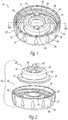
- FIG. 1is a top perspective view of a first embodiment of the vent valve assembly of the present invention
- FIG. 2is a top perspective exploded view of the valve assembly shown in FIG. 1 ;
- FIG. 3is a top perspective view of the bottom cap of the vent valve assembly shown in FIG. 1 ;
- FIG. 4is a bottom perspective view of the bottom cap shown in FIG. 3 ;
- FIG. 5is a side elevation of the bottom cap of FIG. 2 ;
- FIG. 6is a top plan view of the bottom cap of FIG. 5 ;
- FIG. 7is a vertical sectional view as would be seen along line 7 - 7 of FIG. 6 ;
- FIG. 8is a vertical sectional view as would be seen along line 8 - 8 of FIG. 6 ;
- FIG. 9is a bottom plan view of the bottom cap of FIG. 5 ;
- FIG. 10is an enlarged view of a vertical section taken through one of the vent holes in the bottom cap shown in FIG. 7 ;
- FIG. 11is an enlarged view of a vertical section taken through the left portion of the bottom cap of FIG. 7 ;
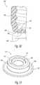
- FIG. 12is a top perspective view of the vent valve shown in FIG. 2 ;
- FIG. 13is a bottom perspective view of the vent valve shown in FIG. 12 ;
- FIG. 14is a side elevation of the vent valve shown in FIG. 12 ;
- FIG. 15is a top plan view of the vent valve shown in FIG. 14 ;
- FIG. 16is a bottom plan view of the vent valve shown in FIG. 14 ;
- FIG. 17is a vertical sectional view as would be seen along line 17 - 17 of FIG. 15 ;
- FIG. 18is a vertical sectional view as would be seen along line 18 - 18 of FIG. 15 ;
- FIG. 19is an enlarged view of the encircled portion of the flap shown in FIG. 18 ;
- FIG. 19Ais an enlarged vertical sectional view, with portions removed, as would be seen along line 19 A- 19 A of the vent valve assembly shown in FIG. 1 ;
- FIG. 20is a schematic of a vertical sectional view taken through a baby bottle whose bottom end is attached or connected to a first embodiment of the vent valve assembly of the present invention shown in FIGS. 1 and 19 ;
- FIG. 21is a top perspective view of a second embodiment of the vent valve assembly of the present invention.
- FIG. 22is a top perspective exploded view of the vent valve assembly shown in FIG. 21 ;
- FIG. 23is a top perspective view of the bottom cap of the vent valve assembly shown in FIG. 21 ;
- FIG. 24is a bottom perspective view of the bottom cap shown in FIG. 23 ;
- FIG. 25is a side elevation of the bottom cap of FIG. 22 ;
- FIG. 26is a top plan view of the bottom cap of FIG. 25 ;
- FIG. 27is a vertical sectional view as would be seen along line 27 - 27 of FIG. 26 ;
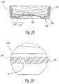
- FIG. 28is a vertical sectional view as would be seen along line 28 - 28 of FIG. 26 ;
- FIG. 29is an enlarged view of a vertical section taken through the encircled vent hole in the bottom cap shown in FIG. 28 ;
- FIG. 30is an enlarged view of a vertical section taken through the left portion of the bottom cap of FIG. 27 ;
- FIG. 31is a top perspective view of the vent valve shown in FIG. 21 ;
- FIG. 32is a bottom perspective view of the vent valve shown in FIG. 21 ;
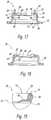
- FIG. 33is a side elevation of the vent valve shown in FIG. 31 ;
- FIG. 34is a top plan view of the vent valve shown in FIG. 33 ;
- FIG. 35is a bottom plan view of the vent valve shown in FIG. 33 ;
- FIG. 36is a vertical sectional view as would be seen alone line 36 - 36 of FIG. 34 ;
- FIG. 37is an enlarged view of the encircled portion of the flap shown in FIG. 36 ;
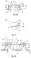
- FIG. 38is an enlarged view of a vertical section through a valve assembly of the second embodiment of the present invention.
- FIG. 39is a vertical sectional view as would be seen along line 39 - 39 of the vent valve assembly of FIG. 21 ;
- FIG. 40is a bottom perspective view of another embodiment of a vent valve assembly of the invention, with a modified vent disc;
- FIG. 41is a top plan view of the vent disc of FIG. 40 ;
- FIG. 42is a vertical sectional view as would be seen along line 42 - 42 of FIG. 41 ;
- FIG. 43is an enlarged vertical section through a vent hole shown in the encircled portion of FIG. 42 ;
- FIG. 44is a bottom perspective view of the vent disc shown in FIG. 41 ;
- FIG. 45is a bottom plan view of the vent valve assembly of FIG. 40 ;
- FIG. 46is a top perspective view of a third embodiment of a vent valve assembly of the present invention, with a modified vent disc;
- FIG. 47is a top perspective exploded view of the vent valve assembly of FIG. 46 ;
- FIG. 48is a bottom perspective view of the vent valve assembly of FIG. 46 ;
- FIG. 49is a top plan view of the modified vent disc of FIG. 47 ;
- FIG. 50is a vertical sectional view as would be seen along line 50 - 50 of FIG. 49 ;
- FIG. 51is an enlarged view of the encircled vertical section through a vent hole in the vent disc of FIG. 50 ;
- FIG. 52is a bottom perspective view of a modified bottom cap that can be employed with a second embodiment of the present invention.
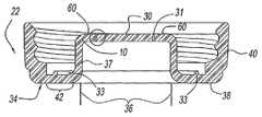
- FIG. 1is a top perspective view of a preferred vent valve assembly of the invention, designated 10 , for attachment or connection to the bottom open end 12 of a liquid dispensing container, for example, a baby bottle 14 ( FIG. 20 ).
- Bottom open end 12typically has a cylindrical neck 16 , a downwardly directed sealing surface 18 , and structure, for example, an external thread 20 , for attaching bottom cap 22 to bottle 14 .
- FIG. 2is an exploded top perspective view of the vent valve assembly of FIG. 1 .
- vent valve assembly 10is comprised of bottom cap 22 , a vent valve 28 , a vent disc 30 and a sealing member 32 .
- bottom cap 22is comprised of a bottom wall 34 having a central portion 36 , a peripheral portion 38 surrounding central portion 36 , and a side wall 40 that extends upwardly from peripheral portion 38 .
- Side wall 40has an interior surface with structure, for example threads, to attach or connect bottom cap 22 to bottom open end 12 of baby bottle 14 .
- Central portion 36includes an upwardly directed inner wall, here exemplarily shown as a cylindrical wall 37 that extends from the radially inner portion of peripheral portion 38 upwardly to and merges with the radially outer portion of vent disc 30 .
- Peripheral portion 38has an interior surface that forms a seat 42 ( FIGS. 6, 7 and 8 ) for receiving a sealing member 32 for sealing bottom cap 22 with the bottom open end of 12 of baby bottle 14 when the two are attached together.
- Sealing member 32can be a conventional sealing structure, for example, a rubber, elastomeric, silicone or other suitable sealing ring (not shown). As will be explained, preferably sealing member 32 is part of vent valve 28 .
- Central portion 36 of bottom wall 34 of bottom cap 22need not be, but preferably is raised relative to peripheral portion 38 of bottom wall 34 .
- Central portion 36preferably includes a rigid vent disc 30 having at least one small hole 31 , preferably a plurality of small holes 31 therethrough.
- Vent disc 30need not be, but as shown in this embodiment, it preferably is, integral or one-piece with, preferably raised, central portion 36 of bottom wall 34 of bottom cap 22 .
- the plurality of vent holes 31shown in this embodiment as six, is preferably arranged in an annular pattern extending about, and preferably within the or a peripheral portion of vent disc 30 . Any suitable number, pattern or arrangement of vent holes can be employed.
- the vent hole or plurality of vent holesis or are to be coordinated with and located in positions so that the vent holes can be covered by the one or more flexible flaps of the present disclosure.
- vent disc 30need not have, but preferably has a roughened or textured surface area or areas radially just outside of or peripheral to the vent hole or holes 31 to provide additional surface area to prevent thin flexible flap 46 from acting like a suction cup and sticking too tightly to the underlying upper surface of vent disc 30 .
- FIGS. 2 and 3show that, for example, when vent holes 31 are arranged in a circular or annular pattern, preferably a portion or all of the peripheral portion of the vent disc located just outside of the array or pattern of vent holes 31 , here an annular portion or pattern, is textured as at 60 . Texturing can be effected by any suitable method, preferably one performed during the bottom cap or vent disc molding process.
- the upper surfaces of the vent discs employed in embodiments of the present disclosurehave a peripheral portion and preferably it is substantially flat.
- the portion(s), e.g., the peripheral portion(s) of the upper surface of vent disc 30 where vent hole(s) 31 reside, and/or the surface area(s) that are textured or that are contacted by flap 46 , (is or)are substantially flat. That which is stated in this paragraph in connection with vent disc 30 also applies to other embodiments of vent discs of the present disclosure.
- internal wall 37 of bottom cap 22is shown as being cylindrical and axially extending, internal wall 37 can be of any suitable shape, e.g., domed, frustoconical, angled or sloped.
- FIG. 5is a side elevation of, and FIG. 6 is a top plan view of bottom cap 22 .
- FIG. 6clearly shows integral vent disc 30 of raised central portion 36 having an annular arrangement or pattern of a plurality of vent holes 31 , and just radially outside of the pattern, an annular peripheral textured surface area 60 .
- FIG. 6also shows seat 42 on the inside surface of peripheral portion 38 (not shown) of bottom wall 34 , for receiving and seating therein a conventional sealing member (not shown) or peripheral sealing flange 32 of vent valve 28 .
- Seat 42includes a raised sealing ridge 33 on and against which the sealing member or peripheral sealing flange 32 is pressed by sealing surface 18 that partly defines the bottom opening of cylindrical neck 16 of baby bottle 14 .
- FIG. 7a vertical section as would be seen along line 7 - 7 of FIG. 6 through vent holes 31 of bottom cap 22
- FIG. 8a vertical section as would be seen along line 8 - 8 of bottom cap 22
- bottom cap 22having bottom wall 34 comprised of raised central portion 36 , peripheral portion 38 and side wall 40 .
- Upwardly directed internal cylindrical wall 37extends from the radially inner portion of peripheral portion 38 to and communicates with the radially outer portion of vent disc 30 .
- FIGS. 7 and 8show that the upper surface of the peripheral portion of vent disc 30 radially just outside of the annular pattern of vent holes 31 has an annular portion 60 that is textured.
- FIG. 9shows bottom cap 22 comprised of bottom wall 34 having a central portion 36 which in turn comprises integral vent disc 30 , peripheral portion 38 surrounding central portion 36 , and a side wall 40 that extends upwardly from peripheral portion 38 .
- FIG. 10an enlarged view of the encircled vertical section portion taken through the left hand vent hole 31 in bottom cap 22 of FIG. 7 , shows that the at least one vent hole 31 or each of the plurality of vent holes 31 preferably has a lower portion 64 and an upper portion 66 .
- Lower portion 64preferably has one or more tapered or frustoconical shaped portions, here shown as first frustoconical portion 68 and second intermediate frustoconical portion 70 .
- Upper portion 66preferably is cylindrical when viewed in vertical section. Desirably, both of frustoconical portions 68 , 70 have larger diameters than upper portion 66 .
- FIG. 11an enlarged view of the left side portion of the bottom cap 22 of FIG. 7 , shows that the inside surface of peripheral portion 38 of bottom wall 34 of bottom cap 22 has a seat 42 with upstanding annular sealing ridge 33 on which can be seated a conventional sealing ring (not shown), or peripheral sealing flange 32 of vent valve 28 shown for example in FIGS. 1 and 2 .
- vent holesare employed in the vent discs of the vent valve assemblies of the disclosure.
- the size of the vent holes employedis sufficiently small to utilize the properties of surface tension of liquid and the capillary action of a liquid passing through a hole to permit reduced levels of suction pressure by the user of the vent valve assemblies, while at the same time preventing leakage through the holes. It has been found that for a baby bottle filled to full capacity of about 5.1 inches of liquid (water), the hole size (diameter) required to utilize these properties to prevent leakage is less than 0.11 mm. Hole sizes that small are impractical because they are very difficult to mold into a bottle component.
- a principle of the present disclosureis to use one or more small vent holes in a rigid disc and cover the hole(s) with a thin flexible baffle or flap to reduce the hydrostatic pressure from an overlying volume of liquid, in this example, about 5.1 inches of liquid, by preventing the overlying liquid from directly contacting and passing directly through the hole(s), while taking advantage of the properties of small holes to prevent leakage of small amounts of liquid through the vent holes. By preventing direct liquid contact, there will not be enough liquid pressure to overcome the hole forces that will allow the liquid to leak through the small vent holes.
- vent hole(s)can be of any suitable shape, preferably the holes are tapered or frustoconical, primarily to make it easier to mold the holes during manufacturing of the parts or components that have the vent holes.
- the vent hole or holescan be cylindrical, tapered or frustoconical, or a combination thereof. While cylindrical vent holes are less preferred since they are more difficult to mold in small diameter sizes, it may be desirable to employ them in certain applications, for example, when it is desired to provide vent discs that are reversible.
- vent hole(s) of vent discs of the inventioni.e., vent discs of or for a bottom cap 22 or of or for mounting to a vent valve of the invention, for a liquid dispensing container or bottle 14 whose capacity is about 5.1 inches of liquid (water)
- the diameter of the cylindrical upper portion 66 of the vent holes at the upper surface of, for example, the central portion 36 of vent disc 30 of bottom wall 34is from about 0.010 inch to about 0.020 inch
- the diameter of the tapered or frustoconical lower portion 64 of the vent holes at the lower surface 64 of the vent discis from about 0.030 inch to about 0.040 inch.
- vent holes of vent discs of the inventioncan be in the range of from about 0.005 inch to about 0.125 inch, preferably from about 0.005 inch to about 0.035 inch.
- vent valve 28is mounted on raised central panel 36 of bottom wall 34 of bottom cap 22 such that flexible flap 46 extends over and covers the plurality of vent holes 31 in underlying vent disc 30 .
- vent valve 28has a top portion generally designated 44 and an upstanding member shown as cylindrical wall 48 that extends upward to and merges with top portion 44 .
- Top portion 44has a thin flexible radially inwardly extending flap 46 that contacts and covers the at least one vent hole 31 the plurality of vent holes 31 of the vent disc employed, such that when the liquid dispensing container, or baby bottle 14 is in an upright position, the weight of the liquid in the container above flap 46 presses the flap down over and closes the at least one vent hole or plurality of vent holes 31 to prevent direct contact of the overlying liquid with and leakage through the vent hole(s).
- top portion 44 of vent valve 28has a peripheral radially inwardly extending outer rim 52 that in turn has an upper surface 54 , a lower surface 56 , and a radially inward depending inner wall 58 joining upper surface 54 and lower surface 56 .
- flap 46can extend radially inward from any portion of top rim 44 or any portion of depending inner wall 58 , preferably flap 46 extends radially inward from a lower portion of depending inner wall 58 ( FIGS. 17-19 ).
- Vent valve 28can have one or more protrusions placed at one or more convenient, accessible locations to facilitate grasping thereof and removal of vent valve 28 from or placement of vent valve 28 on raised central portion 36 of bottom cap 22 , and/or if necessary from or on upstanding cylindrical wall 48 .
- upper surface 54 of outer rim 52 of vent valve 28can have two upwardly extending grasping tabs 62 disposed 180 degrees from each other to facilitate removal or replacement of vent valve 28 .
- FIG. 12is a top perspective view of vent valve 28 as it is shown and discussed in connection with the exploded view of vent assembly 10 of FIG. 2 .
- FIG. 12shows that upstanding member 48 preferably is a wall or the like, preferably a cylindrical wall, and upstanding member 48 has a base portion 50 that merges with a sealing member 32 , preferably comprising a peripheral sealing flange that integrally extends radially outward from base portion 50 of upstanding member 48 and sits in seat 42 formed by the interior surface of peripheral portion 38 of bottom cap 22 .
- FIG. 13a bottom perspective view of vent valve 28 of FIG. 12 , shows that lower surface 56 of outer rim 52 of top portion 44 extends radially inward into radially inwardly extending thin flexible annular flap 46 having a radially inner edge 47 .
- FIG. 13also shows the bottom surface of peripheral sealing flange 32 , and the interior surface of generally cylindrical wall 48 , here shown as a having two visible interior threads, and a radially outwardly extending annular groove 90 formed at the junction of cylindrical wall 48 and lower surface 56 of outer rim 52 .
- FIG. 14a side elevation of vent valve 28 of FIG. 12 , shows basically the same elements as shown in FIG. 12 .
- FIG. 15a top plan view of vent valve 28 of FIG. 14 , shows peripheral sealing flange 32 , upstanding wall 48 , top portion 44 , outer rim 52 , upper surface 54 , and inner wall 58 that depends downwardly from outer rim 52 and from which radially inwardly extends annular flap 46 .
- Flap 46has radially inwardly extending annular inner edge 47 that defines a central opening CO.
- FIG. 15also shows opposed grasping tabs 62 extending upwardly from outer rim 52 .
- FIG. 16a bottom plan view of vent valve 28 of FIG. 14 , shows radially outwardly extending peripheral flange 32 , and moving radially inward from it, the inside surface of upstanding member 48 .
- the inside surfacehas a first undercut 80 , a first transition portion 82 , a second undercut 84 , a second transition portion 86 , and an abutment surface 88 .
- abutment surface 88is a radially outward groove 90 that is available, but in this embodiment (which employs an integral vent disc 28 ) groove 90 is not used for mounting a vent disc therein.
- FIGS. 17 and 18are vertical sectional views as would be seen respectively along line 17 - 17 , and line 18 - 18 , of FIG. 15 .
- FIGS. 16 and 17each show the features of the inside surface of upstanding member 48 that were shown in plan view and discussed in connection with FIG. 15 .
- vent valve 28is easily mountable on and removable from central portion 36 , and, when it is mounted thereon, or otherwise cooperatively related with the vent disc in accordance with this disclosure, their respective vertical axes are fairly co-linear, or the respective components of the vent valve assembly 10 of the invention (vent disc 30 and vent valve 28 ) are concentrically or otherwise cooperatively aligned, so that flap 46 , or multiple flaps, however designed, cover(s) and operate(s) as intended with respect to vent hole(s) 31 of vent disc 30 .
- upstanding member 48may be desirable to design the inside surface of upstanding member 48 to merely employ or include an inwardly angled lead-in surface to facilitate the mounting of vent valve 28 onto central portion 36 of bottom cap 22 and to stabilize vent valve 28 relative to central portion 36 once vent valve 28 is mounted thereon.
- vent valve 28has a top portion generally designated 44 and an upstanding member 48 , here a cylindrical wall, that extends upward to and merges with top portion 44 .
- Top portion 44has a thin flexible radially inwardly extending flap 46 that contacts and covers the at least one hole 31 or the plurality of holes 31 of the vent disc employed. (See FIGS. 20, 20A ).
- top portion 44 of vent valve 28has a peripheral radially inwardly extending outer rim 52 that in turn has an upper surface 54 , a lower surface 56 , and a radially inward depending wall 58 joining upper surface 54 and lower surface 56 .
- flap 46can extend radially inward from any portion of top portion 44 or any portion of inner depending wall 58 , preferably flap 46 extends radially inward from depending wall 58 , desirably from a lower portion thereof.
- FIG. 19an enlarged view of the encircled portion of flap 46 shown in FIG. 18 , clearly shows that flap 46 preferably extends radially inward from the bottom portion of depending wall 58 .
- FIG. 19also shows that flap 46 preferably curves or arcs downwardly as it extends radially inwardly from depending wall 58 . This provides a desirable downward bias to flap 46 .
- the undersurface of the flap at least at or adjacent radially inner edge 47 of flap 46will contact or rest upon the top surface of vent disc 30 of central portion 36 of bottom cap 22 , and cover the at least one vent hole 31 or plurality of vent holes 31 of vent disc 30 .
- lower surface 56 of outer rim 52typically will tightly contact or rest upon the top surface of vent disc 30 of central portion 36 of bottom cap 22 . It has been found that curved flaps, as shown, improve sealing of the flap to the vent disc surface, as compared with normally or initially flat flaps. The curvature of the flap diminishes with the increased over pressure of the liquid. With reduced over pressure, the thinned radially inner edge 47 of flap 46 , especially with lower durometers, sticks better to the vent disc to prevent minor liquid seepage or leakage under the flap.
- FIG. 19Ais an enlarged vertical sectional view, with portions excluded, as would be seen along line 19 A- 19 A of vent valve assembly 10 shown in FIG. 1 .
- FIG. 19Ashows vent valve assembly 10 , comprised of bottom cap 22 and vent valve 28 mounted on raised central portion 36 and on peripheral portion 38 of bottom cap 22 . More particularly, vent valve 28 has peripheral portion 32 seated in seat 42 and resting on ridge 33 , for sealing vent assembly 10 with container 14 when the two are attached or connected together ( FIG. 20 ).
- Peripheral portion 32merges into upstanding member 48 which merges into top portion 44 and is generally parallel to and has an abutment portion 88 that abuts against an upper portion of internal wall 37 of bottom cap central portion 36 .
- Vent valve 28has top rim 52 that has an inner depending annular wall 58 from the lower portion of which annular, curved flap 46 with radially inner edge 47 extends. Flap 46 covers vent holes 31 in accordance with the invention.
- FIG. 20is a schematic of a vertical sectional view taken through a liquid dispensing baby bottle 14 whose bottom open end 12 is sealingly attached or connected to a preferred vent valve assembly 10 of FIGS. 1 and 19 .
- Bottom open end 12typically has a cylindrical neck 16 , a downwardly directed sealing surface 18 , and structure, for example, an external thread 20 , for attaching or connecting bottom cap 22 to bottle 14 .
- flap 46preferably has an annular configuration. Radially inner edge 47 of flap 46 defines a central opening CO through which venting air that passes through vent holes 31 enters the interior of the container or bottle to relieve the vacuum created during feeding.
- Flexible flap 46can comprise or be made of silicone, elastomer, thermoplastic urethane, or natural or synthetic rubber. It is not required, but it is preferable that the entirety of vent valve 28 be made of the same material. Preferably, flexible flap 46 and preferably the entirety of vent valve 28 is made of silicone, or elastomer.
- Flap 46 of the present disclosureis made of a thin flexible material.
- thicknessit is meant that the thickness of the flap can be within a broad range of from about 0.005 inch to about 0.060 inch, more preferably from about 0.005 inch to about 0.030 inch and most preferably from about 0.007 inch to about 0.017 inch, depending, for example, on the material of which the flap is made, the durometer of the material, and the flexibility desired for the particular application. It is contemplated that the activation pressure to flex or move the flap and open the vent hole(s) can be varied as desired by varying the thickness, durometer and/or type of silicone or other material.
- the liquid flow rate of nipples for baby bottlescan be varied as desired by varying one or more of the same factors.
- the durometer of the materialcan be broadly within the range of from about 30 to about 85. Below about 30, the materials may tend be too sticky for the suction pressures, e.g., low, desired for the application, and above 80 the materials may tend be too hard for the suction pressures desired. A more preferred range would be from about 30 to about 70 durometer.
- flaps 46that are about 0.020 inch thick where they join or extend from the bottom portion of depending wall 58 of top rim 52 of vent valve 28 , and that taper gradually as they extend radially outward to a thickness of about 0.012 inch at radially inner edge 47 .
- These thicknesseswere suitable for annular flaps that are about 0.250 inch wide, of a vent valve made of 50 durometer silicone, for use in a baby bottle having a nipple for dispensing, and that was filled to a capacity of about 5.1 inches of water.
- the diameter of the cylindrical upper portion 66 of the vent holes at the upper surface of central portion 36 of vent disc 30 of bottom wall 34was from about 0.010 inch to about 0.030 inch, and the diameter of the tapered or frustoconical lower portion 64 of the vent holes at the lower surface of the central portion 36 or vent disc 30 of bottom wall 34 was from about 0.030 inch to about 0.060 inch.
- the thickness and/or the durometer of the baffle or flapcan be varied to vary the venting rate and/or venting ease.
- features and elements having 3 digit 100 to 199 series of reference numbers (without a prime symbol) that incorporate the 2 digit reference numbers previously used in connection with FIGS. 1 through 20are basically the same as and operate basically the same as the features and elements having the 2 digit numbers 10 through 99 used in connection with FIGS. 1 through 20 , for example, “vent valve 28 ” and “vent valve 128 ”.
- Features and elements having the 100 to 199 series of reference numbers additionally indicated with a prime symboldenotes that the feature or element is different or operates differently in some respect that will be described.
- Vent valve assembly 100 as shown in FIG. 21is similar to vent assembly 10 shown in FIG. 1 , except that vent valve 128 does not have grasping tabs 62 , and bottom cap 122 ′ and its bottom wall 134 ′ are different in one important respect, that vent disc 130 ′ is not integral with bottom wall 134 ′, but rather is a separate piece or element that is removably mounted to vent valve 128 in a manner to be explained.
- FIG. 22is an exploded top perspective view of the vent valve assembly 100 ′ of FIG. 21 .
- vent valve assembly 100 ′is comprised of bottom cap 122 ′, vent valve 128 and a separate vent disc 130 ′.
- vent valve assembly 100 ′is a double vented system.
- Bottom cap 122 ′is comprised of a bottom wall 134 ′ having a central portion 136 ′, a peripheral portion 138 ′ that surrounds central portion 136 ′, and a side wall 140 .
- Central portion 136 ′ of bottom wall 134 ′need not be, but preferably is raised relative to peripheral portion 138 ′ of bottom wall 134 ′.
- Central portion 136 ′includes an upwardly directed inner wall 137 ′, here exemplarily shown as arcuate and frustoconical, that extends from the radially inner portion of peripheral portion 138 ′ upwardly to and merges with the radially outer portion of central panel 135 ′.
- Central panel 135 ′has at least one small hole H, preferably a plurality, shown in FIG. 22 as twelve small holes H therethrough.
- Central panel 135 ′need not be, but as shown in this embodiment, it preferably is, integral or one-piece with, preferably raised, central portion 136 ′ of bottom wall 134 ′ of bottom cap 122 ′.
- Upwardly directed inner wall 137 ′can be of any suitable shape or height, for example, domed, angled, stepped, sloped or a combination thereof.
- Peripheral portion 138 ′has an interior surface that forms a seat 142 ′ for receiving a sealing member 132 .
- Sealing member 132can be a conventional sealing structure (not shown), made, for example, of rubber, elastomeric, silicone or other suitable sealing ring material(s).
- sealing member 132is peripheral sealing flange 132 or some other part of vent valve 128 .
- FIG. 25is a side elevation of the bottom cap
- FIG. 26is a top plan view
- FIGS. 27 and 28are vertical sectional views taken through FIG. 26
- FIG. 29is an enlargement of an encircled portion of FIG. 28 through a vent hole H
- FIG. 30is an enlargement of a portion of FIG. 28 . More particularly, these Figures show peripheral portion 138 ′, upwardly directed inner arcuate or frustoconical wall 137 ′ and basically flat raised central panel 135 ′ of bottom wall 134 ′.
- FIG. 29shows an embodiment of holes H in central panel 135 ′, wherein preferably small holes H are a combination of a cylindrical portion at the top surface and a frustoconical portion at the lower surface of bottom wall 134 ′.
- small holes Hare a combination of a cylindrical portion at the top surface and a frustoconical portion at the lower surface of bottom wall 134 ′.
- the same design of small holesmay be used for the vent holes 131 ′ of vent disc 130 ′.
- Vent valve 128 of the second embodiment of the present disclosureis basically the same as, and operates basically the same as vent valve 28 described earlier in connection with the first preferred embodiment of the invention.
- vent valve 128 shown in and described in connection with FIGS. 21, 22, 31 through 40 and 46is basically the same and operates basically the same as vent valve 28 shown in and described in connection with FIGS. 2, 12, 13 through 19 , 19 A and 20 .
- One minor difference between vent valve 128 and vent valve 28is that vent valve 128 is presented without grasping tabs 62 .
- Another differenceis in the manner in which vent valve 128 relates to and cooperates with vent disc 130 ′.
- vent disc 130 ′is an individual or separate member that is mounted to upstanding member or wall 148 . More particularly, referring to FIG. 36 , the inside surface of upstanding member 148 , here shown as a cylindrical wall, of vent valve 128 has a radially outwardly extending annular groove 190 formed therein for removably mounting a vent disc, e.g., 130 ′ (not shown) therein.
- Groove 190need not be but preferably is annular and located at the junction of the inside surface of upstanding wall 148 and lower surface 156 of top rim 152 . Groove 190 need not be but preferably is unbroken or continuous.
- the inside surface of upstanding member 181starting at its lowest extent, has a first undercut 180 , a first transition portion 182 , a second undercut 84 , a second radially inwardly extending angled transition portion 186 , and a radially inwardly extending abutment surface 188 .
- the lower surface of groove 190terminates at a radially inward edge of depending inside surface abutment portion 188 of upstanding wall 148 .
- FIG. 38is an enlarged vertical sectional view through a portion of a vent valve assembly of the second embodiment 100 ′ of the present disclosure. More particularly, FIG. 38 shows a circular vent disc 130 ′ removably press fit mounted tightly into annular groove 190 of vent valve 128 . Vent disc 130 ′ has a peripheral outer edge or rim 192 , and the lower surface of vent disc 130 ′ includes at least one depending member that is radially inwardly offset from the peripheral outer edge or rim 192 , so that the at least one depending member abuts the inside surface of the upstanding wall 148 of vent valve 128 .
- the at least one memberpreferably is or includes an annular depending skirt 191 that abuts abutment surface 188 to stabilize and help secure vent disc 130 ′ in place in vent valve 128 .
- FIG. 38also shows annular flap 146 covering vent holes 131 ′. Although flap 146 is shown extending through the thickness of vent disc 130 ′, flap 146 covers vent holes 131 ′, this showing is done merely to show that flap 146 in its normal condition is curved downward and biased against the top surface of vent disc 130 ′.
- FIG. 38shows that in this embodiment of vent disc, vent holes 131 ′ are tapered or frustoconical.
- Vent disc 130 ′is shown as a separate piece and having a plurality of six small vent holes 131 arranged in a circular or annular pattern extending about, and preferably within a peripheral portion of vent disc 130 ′.
- FIG. 39is a vertical sectional view through a portion of the second embodiment of the vent valve assembly 100 ′ of the present disclosure.
- Vent valve assembly 100 ′is an example of a double vent system in that there are two layers of small vent holes, those designated 131 ′ in vent disc 130 ′ positioned just below flap 146 , and those designated H in underlying bottom wall 134 ′ of bottom cap 122 .
- the second layer of holesis not necessary, it is desirable because it acts as a safety venting system, to prevent leakage from bottom cap 122 ′ in case some liquid seeps through the top layer of holes or in case some liquid migrates around the top venting disk.
- the second layer of holescan have one or more holes.
- vent discsneed not be mounted to vent valve 128 or 28 by being press fit mounted for removal from or mounting to groove 190 for example by bending and flexing vent valve 128 .
- vent discs of the present disclosurecan be mounted to vent valves of the present disclosure by molding, co-molding or bonding them together.
- FIGS. 40 through 45basically show an alternative, modified vent disc 130 ′′ and show it mounted in a vent valve of the disclosure. More particularly, FIG. 40 shows a bottom perspective view of vent valve 128 having press fit mounted in the groove thereof (not shown) vent disc 130 ′′ modified in that it has an elongated grasping strut 196 integrally formed on and depending the bottom surface of disc 130 ′′. As shown, preferably the opposite ends of strut 196 join depending skirt 191 . Aside from facilitating grasping of disc 130 ′′, strut 196 helps to rigidify the disc.
- FIG. 41 and FIG. 42show that vent disc 130 ′′ is circular and has a rounded or chamfered annular peripheral rim 192 that is suited to fit tightly in groove 190 of vent valve 128 .
- FIG. 43is an enlarged view of the encircled the combination frustoconical (lower) and vent cylindrical (upper) vent hole 131 shown in FIG. 42 .
- FIG. 44a bottom perspective view of vent disc 130 ′′, shows that elongated strut 192 preferably is integrally molded at its opposite ends to depending skirt 191 .
- FIG. 45is a bottom plan view of vent disc 130 ′′ press fit mounted to vent valve 128 .
- FIGS. 46 through 51show a third embodiment of a vent valve assembly 100 ′′ of the present disclosure, the vent valve assembly having a further modified vent disc.
- FIG. 46shows vent valve assembly 100 ′′ is comprised of bottom cap 122 ′, vent valve 128 , and vent disc 130 ′′′. Vent disc 130 ′′′ is reversible. Each of its upper and lower surfaces is a mirror image of the other. More particularly, as shown in FIGS. 46, 47, 49 and 50 , which show upper surface US, (and as shown in FIG.
- each surface of disc 130 ′′′has a first radially annular peripheral outer rim or edge 192 having a rounded edge, for being press fit into groove 190 , a next or second radially inward annular peripheral portion or area 193 that is textured, and within which is positioned vent holes 131 ′′, and a next radially inward central portion 194 , within which is situated a diametrically disposed, semi-circular grasping tab 195 . Since vent holes 131 ′′ are cylindrical, there will not be any variation in vent flow through vent holes 131 ′′ regardless of whether, relative to the upper dispensing end of baby bottle 14 , upper surface US of vent disc 130 ′′′ is facing upward.
- FIG. 52is a bottom perspective of a modified bottom cap 122 ′′ that can be employed in embodiments of contemplated vent valve assemblies of the present disclosure that employ a double venting system.
- vent holes Hdesignated H 1 and H 2
- FIG. 52also shows that holes H can be of any desired shape, and that variously shaped holes can be combined in the same bottom wall 134 ′′.
- FIG. 52further shows that the shape of central portion 135 ′′ can be any suitable shape, including domed.
- Bottom cap 122 ′′is especially suitable for being employed with embodiments of vent valve assemblies of the invention utilizing a vent valve 28 , 128 with a separate vent disc that is mounted to the vent valve.
- Vented parts of the vent valve assemblies of the present disclosurecan be made of any suitable rigid material or materials, for example, a thermoplastic, polypropylene, polyethylene, acrylonitrile butadiene styrene or polycarbonate.
- ventherein is meant that the part is substantially rigid, that is, it does not have to be absolutely rigid.
- the partis rigid enough to perform as intended.
- a vent discmay exhibit some flexing under great stress, the disc will not flex under contemplated stresses to, for example, be partly or fully dislodged during use or cleaning from its mounting groove, or be distorted enough to affect the vent hole size and change its designed vent flow characteristics.
Landscapes
- Engineering & Computer Science (AREA)
- General Health & Medical Sciences (AREA)
- Animal Behavior & Ethology (AREA)
- Health & Medical Sciences (AREA)
- Public Health (AREA)
- Veterinary Medicine (AREA)
- Life Sciences & Earth Sciences (AREA)
- Mechanical Engineering (AREA)
- General Engineering & Computer Science (AREA)
- Closures For Containers (AREA)
- Self-Closing Valves And Venting Or Aerating Valves (AREA)
- Cookers (AREA)
- Check Valves (AREA)
Abstract
Description
Claims (12)
Priority Applications (4)
| Application Number | Priority Date | Filing Date | Title |
|---|---|---|---|
| US14/036,949US10500137B2 (en) | 2006-12-20 | 2013-09-25 | Vent valve assemblies for baby bottles |
| US14/813,465US20150335534A1 (en) | 2006-12-20 | 2015-07-30 | Vent Valve Assemblies For Baby Bottles |
| US16/297,951US11400024B2 (en) | 2006-12-20 | 2019-03-11 | Vent valve assemblies for baby bottles |
| US17/811,406US12440423B2 (en) | 2022-07-08 | Vent valve assemblies for baby bottles |
Applications Claiming Priority (4)
| Application Number | Priority Date | Filing Date | Title |
|---|---|---|---|
| US87589906P | 2006-12-20 | 2006-12-20 | |
| US12/004,129US8016142B2 (en) | 2006-12-20 | 2007-12-20 | Vent valve assemblies for baby bottles |
| US13/053,789US8567619B2 (en) | 2006-12-20 | 2011-03-22 | Vent valve assemblies for baby bottles |
| US14/036,949US10500137B2 (en) | 2006-12-20 | 2013-09-25 | Vent valve assemblies for baby bottles |
Related Parent Applications (1)
| Application Number | Title | Priority Date | Filing Date |
|---|---|---|---|
| US13/053,789DivisionUS8567619B2 (en) | 2006-12-20 | 2011-03-22 | Vent valve assemblies for baby bottles |
Related Child Applications (1)
| Application Number | Title | Priority Date | Filing Date |
|---|---|---|---|
| US14/813,465ContinuationUS20150335534A1 (en) | 2006-12-20 | 2015-07-30 | Vent Valve Assemblies For Baby Bottles |
Publications (2)
| Publication Number | Publication Date |
|---|---|
| US20140027403A1 US20140027403A1 (en) | 2014-01-30 |
| US10500137B2true US10500137B2 (en) | 2019-12-10 |
Family
ID=39563086
Family Applications (5)
| Application Number | Title | Priority Date | Filing Date |
|---|---|---|---|
| US12/004,129Active2029-06-20US8016142B2 (en) | 2006-12-20 | 2007-12-20 | Vent valve assemblies for baby bottles |
| US13/053,789Active2027-12-27US8567619B2 (en) | 2006-12-20 | 2011-03-22 | Vent valve assemblies for baby bottles |
| US14/036,949ActiveUS10500137B2 (en) | 2006-12-20 | 2013-09-25 | Vent valve assemblies for baby bottles |
| US14/813,465AbandonedUS20150335534A1 (en) | 2006-12-20 | 2015-07-30 | Vent Valve Assemblies For Baby Bottles |
| US16/297,951Active2029-09-15US11400024B2 (en) | 2006-12-20 | 2019-03-11 | Vent valve assemblies for baby bottles |
Family Applications Before (2)
| Application Number | Title | Priority Date | Filing Date |
|---|---|---|---|
| US12/004,129Active2029-06-20US8016142B2 (en) | 2006-12-20 | 2007-12-20 | Vent valve assemblies for baby bottles |
| US13/053,789Active2027-12-27US8567619B2 (en) | 2006-12-20 | 2011-03-22 | Vent valve assemblies for baby bottles |
Family Applications After (2)
| Application Number | Title | Priority Date | Filing Date |
|---|---|---|---|
| US14/813,465AbandonedUS20150335534A1 (en) | 2006-12-20 | 2015-07-30 | Vent Valve Assemblies For Baby Bottles |
| US16/297,951Active2029-09-15US11400024B2 (en) | 2006-12-20 | 2019-03-11 | Vent valve assemblies for baby bottles |
Country Status (10)
| Country | Link |
|---|---|
| US (5) | US8016142B2 (en) |
| EP (1) | EP2101715A4 (en) |
| JP (1) | JP4991877B2 (en) |
| KR (1) | KR101155247B1 (en) |
| CN (4) | CN103110524B (en) |
| AU (1) | AU2007338783A1 (en) |
| BR (1) | BRPI0720391A2 (en) |
| CA (1) | CA2673401C (en) |
| MX (1) | MX2009006820A (en) |
| WO (1) | WO2008079282A2 (en) |
Cited By (2)
| Publication number | Priority date | Publication date | Assignee | Title |
|---|---|---|---|---|
| US20220339075A1 (en)* | 2006-12-20 | 2022-10-27 | Angelcare Feeding Usa, Llc | Vent valve assemblies for baby bottles |
| US12440423B2 (en)* | 2022-07-08 | 2025-10-14 | Jmbh Holdings, Llc | Vent valve assemblies for baby bottles |
Families Citing this family (59)
| Publication number | Priority date | Publication date | Assignee | Title |
|---|---|---|---|---|
| US8863969B2 (en) | 2007-09-04 | 2014-10-21 | Chantal Lau | Feeding bottle system |
| CA2711072A1 (en)* | 2008-01-11 | 2009-07-16 | Ball Corporation | Method and apparatus for providing a positive pressure in the headspace of a plastic container |
| US9066791B2 (en)* | 2008-08-01 | 2015-06-30 | HaberVision LLC | Ventilation system for goggles |
| US8915387B2 (en)* | 2008-08-11 | 2014-12-23 | University Of South Carolina | Nursing bottle apparatus for improvement of suckling |
| CH701676A1 (en)* | 2009-08-20 | 2011-02-28 | Medela Holding Ag | Teat. |
| US9296531B2 (en)* | 2010-01-12 | 2016-03-29 | Medela Holding Ag | Container with sealed cap and venting system |
| US8727147B2 (en)* | 2010-02-11 | 2014-05-20 | Handi-Craft Company | Bottle assembly having bottom vent |
| US8810374B1 (en)* | 2010-02-11 | 2014-08-19 | Elizabeth Giegoldt | Locating system for child accessories |
| US20110284491A1 (en)* | 2010-05-21 | 2011-11-24 | Handi-Craft Company | Nipple for an infant bottle assembly having a flow control valve and an infant bottle assembly having such a nipple |
| US8567158B2 (en) | 2010-08-06 | 2013-10-29 | Ball Corporation | Container end closure with optional secondary vent opening |
| US10017295B2 (en) | 2010-08-06 | 2018-07-10 | Ball Corporation | Container end closure with optional secondary vent opening |
| US10596073B1 (en) | 2010-11-22 | 2020-03-24 | Mimijumi, Llc | Feeding bottle |
| JP5666336B2 (en)* | 2011-02-15 | 2015-02-12 | 東海興業株式会社 | Composite molded product |
| BRDI7105038S (en)* | 2011-03-29 | 2013-12-10 | CONFIGURATION APPLIED ON WOODEN NOZZLE | |
| USD691039S1 (en)* | 2011-10-27 | 2013-10-08 | Ball Corporation | Vented container end closure |
| CN104364164B (en) | 2011-11-04 | 2017-08-22 | 鲍尔公司 | Ventilation metal end, ventilation container for drink and the method for opening container for drink |
| EP2785306B1 (en)* | 2011-12-01 | 2019-02-13 | Munchkin, Inc. | System and method for venting, priming and modifying a flow rate of fluid from a container |
| CN102626370B (en)* | 2012-04-28 | 2014-09-17 | 庞永国 | Feeding bottle |
| CN103523359B (en)* | 2012-07-02 | 2017-06-09 | 株式会社利其尔 | beverage container for infant |
| USD720464S1 (en) | 2012-08-22 | 2014-12-30 | Tomy International, Inc. | Baby bottle |
| USD720465S1 (en) | 2012-08-22 | 2014-12-30 | Tomy International, Inc. | Valve |
| US20150290086A1 (en)* | 2012-08-22 | 2015-10-15 | Ruth Prentice | Bottom-vented baby bottle |
| USD708758S1 (en)* | 2012-08-24 | 2014-07-08 | Symmetry Medical New Bedford, Inc. | Metal bellow valve |
| USD715144S1 (en) | 2012-11-13 | 2014-10-14 | Ball Corporation | Vented container end closure |
| USD715647S1 (en) | 2012-11-28 | 2014-10-21 | Ball Corporation | Vented end closure |
| CN103070776A (en)* | 2013-01-16 | 2013-05-01 | 蒋一新 | Pressure adjusting structure of ventilating bottle |
| CN105102332B (en) | 2013-03-15 | 2016-12-28 | 鲍尔公司 | There is the end cap of the secondary blow vent that draw ring activates |
| CN103405344B (en)* | 2013-05-24 | 2015-09-23 | 孙庆扬 | A kind of feeding bottle with return-air function |
| US10166172B2 (en)* | 2013-07-10 | 2019-01-01 | Handi-Craft Company | Dual configuration bottle assembly |
| HK1232117A1 (en)* | 2014-02-16 | 2018-01-05 | T.T.Y. General Trade Lines Ltd. | Vented liquid container |
| CA2950702C (en)* | 2014-06-04 | 2020-12-01 | Gino Rapparini | Reinforcement ring for capsules for obtaining beverages |
| US9714115B2 (en) | 2014-07-30 | 2017-07-25 | Ball Corporation | Vented container end closure |
| CN104161675B (en)* | 2014-09-05 | 2017-08-01 | 周潜 | A kind of multifunctional feeding bottle |
| US20160106628A1 (en)* | 2014-10-16 | 2016-04-21 | Handi-Craft Company | Dual configuration bottle assembly |
| US9907731B2 (en) | 2014-11-20 | 2018-03-06 | Chantal Lau | Self-paced ergonomic infant feeding bottle |
| WO2016123267A1 (en)* | 2015-01-27 | 2016-08-04 | Ivation, LLC | Baby bottle |
| US10926007B2 (en)* | 2015-07-13 | 2021-02-23 | Conmed Corporation | Surgical suction device that uses positive pressure gas |
| AT517741B1 (en) | 2015-09-23 | 2019-03-15 | Mam Babyartikel | container |
| KR200484185Y1 (en) | 2015-10-15 | 2017-08-09 | 명의전 | Feeding bottle |
| USD824040S1 (en) | 2016-02-25 | 2018-07-24 | Abbott Laboratories | Bottle |
| CN113925782B (en) | 2016-04-21 | 2024-05-07 | 梅伯恩(英国)有限公司 | Bottle assembly and valve assembly |
| CN106139283A (en)* | 2016-07-28 | 2016-11-23 | 深圳市偶家信息科技有限公司 | Breast pump |
| US20180134538A1 (en)* | 2016-11-17 | 2018-05-17 | Tom Kim | Drink Containers |
| USD799888S1 (en)* | 2016-11-23 | 2017-10-17 | Emerson Electric Co. | Baffle for food waste disposer |
| USD799890S1 (en)* | 2016-11-23 | 2017-10-17 | Emerson Electric Co. | Baffle for food waste disposer |
| USD799889S1 (en)* | 2016-11-23 | 2017-10-17 | Emerson Electric Co. | Baffle for food waste disposer |
| EP3372218A1 (en)* | 2017-03-09 | 2018-09-12 | Koninklijke Philips N.V. | Feeding bottle device |
| US20210292057A1 (en)* | 2017-04-07 | 2021-09-23 | Huntsman Advanced Materials Licensing (Switzerland) Gmbh | Valve device, lid assembly, container and usage thereof |
| US10864144B1 (en)* | 2017-11-15 | 2020-12-15 | David B. Skaggs | Baby bottle assembly |
| KR101915415B1 (en) | 2017-12-04 | 2018-11-05 | 양진석 | Bady bottle for small children combineed with silicone tube |
| US11007122B2 (en) | 2018-03-02 | 2021-05-18 | Handi-Craft Company | Bottle assembly |
| JP7126772B2 (en)* | 2019-02-28 | 2022-08-29 | 株式会社吉野工業所 | cap and container |
| IT201900006873A1 (en)* | 2019-05-15 | 2020-11-15 | Artsana Spa | Membrane for ventilation from the bottom of the bottle of a baby bottle |
| CN110374883B (en)* | 2019-08-28 | 2024-04-02 | 浙江大元泵业股份有限公司 | Automatic exhaust device of built-in well pump |
| USD960667S1 (en)* | 2020-06-16 | 2022-08-16 | Bacardi & Company Limited | Strainer for cocktail shaker |
| IL275502A (en)* | 2020-06-18 | 2022-01-01 | Agaloo Ltd | Vent system |
| US20240270433A1 (en)* | 2021-06-08 | 2024-08-15 | PAPACKS SALES GmbH | Molded product with connection element |
| JP2024112700A (en)* | 2023-02-08 | 2024-08-21 | 株式会社島津製作所 | Cover member for sample storage container |
| CN219822290U (en)* | 2023-04-04 | 2023-10-13 | 睿斯博科技(深圳)有限公司 | Soft drink bottle leak protection lid and drink bottle |
Citations (120)
| Publication number | Priority date | Publication date | Assignee | Title |
|---|---|---|---|---|
| US357439A (en) | 1887-02-08 | Nursing-bottle | ||
| US362554A (en) | 1887-05-10 | James suydam | ||
| US577199A (en) | 1897-02-16 | Nipple | ||
| US886984A (en) | 1907-11-01 | 1908-05-05 | Kleber C Jopling | Massaging device. |
| US921387A (en) | 1908-06-25 | 1909-05-11 | Edward E Etter | Nursing-bottle. |
| US1972895A (en) | 1933-08-28 | 1934-09-11 | Maccoy Frank | Feeding device |
| US1976450A (en) | 1932-04-27 | 1934-10-09 | Lowe Norman Charles | Nursing bottle |
| US1982538A (en) | 1932-06-04 | 1934-11-27 | Mueller Co | Shower head |
| US2043186A (en) | 1936-01-04 | 1936-06-02 | William A O'dette | Nursing bottle |
| US2060212A (en) | 1935-06-29 | 1936-11-10 | Herstein Abe | Baby bottle cap and nipple |
| US2084099A (en) | 1929-11-20 | 1937-06-15 | Cilocon Corp | Valve for feeding devices |
| US2349722A (en) | 1942-03-14 | 1944-05-23 | Oil Devices | Pot type burner and improved air supply means therefor |
| US2365947A (en) | 1941-08-26 | 1944-12-26 | Hygeia Nursing Bottle Company | Nursing bottle |
| US2394722A (en) | 1943-09-21 | 1946-02-12 | Sloane Milton | Nursing bottle |
| US2414697A (en)* | 1945-09-11 | 1947-01-21 | Everett W Pettersson | Infant's drinking cup |
| US2425609A (en)* | 1945-01-02 | 1947-08-12 | Continental Can Co | Sheet metal container with vent opening |
| US2525745A (en) | 1947-06-27 | 1950-10-10 | Keith H Wycoff | Nursing unit |
| US2543163A (en) | 1948-02-24 | 1951-02-27 | Greiner Leonard | Bottling or dispensing container |
| US2546681A (en) | 1948-07-13 | 1951-03-27 | Harold J Searer | Combination sealing disk and nipple holder for nursing units |
| US2582489A (en) | 1949-05-09 | 1952-01-15 | Rudolph E Krueger | Pressure sealing bottle cap |
| FR1058610A (en) | 1952-06-21 | 1954-03-17 | Perfected bottle | |
| US2715980A (en) | 1950-10-09 | 1955-08-23 | Leo M Harvey | Liquid handling dispenser |
| US2729505A (en) | 1951-04-05 | 1956-01-03 | Salmon C Harvey | Lather foam dispenser |
| US2774500A (en) | 1956-01-18 | 1956-12-18 | Deno J Budiani | Infant nursing device |
| US2851201A (en) | 1955-02-01 | 1958-09-09 | Edward J Poitras | Automatic vent stopper |
| US2876935A (en) | 1958-06-06 | 1959-03-10 | David P Lindberg | Criminal apprehension aid |
| US2888685A (en) | 1957-11-05 | 1959-06-02 | Giangrosso Carlo | Toilet deodorizing device |
| US2898007A (en) | 1956-01-17 | 1959-08-04 | Flo Container Inc | Elastic container with reciprocating plunger |
| US2907485A (en) | 1958-06-09 | 1959-10-06 | Robert K Lunden | Baby nursing and feeding bottle |
| US2960088A (en) | 1959-02-16 | 1960-11-15 | Nursmatic Corp | Nipple for baby nursing bottle |
| US2965310A (en) | 1957-03-06 | 1960-12-20 | Jones & Laughlin Steel Corp | Sprinkling can |
| US2982432A (en) | 1959-02-25 | 1961-05-02 | Ross M Mehl | Nursing unit |
| US3113687A (en) | 1961-07-13 | 1963-12-10 | Butts Richard Raymond | Nursing bottle construction |
| US3134495A (en) | 1962-09-14 | 1964-05-26 | Carbonel Richard Joseph | Vented nursing bottle |
| US3217574A (en) | 1964-01-24 | 1965-11-16 | Abbott Lab | Apparatus for shearing an elastomeric cellular material |
| US3247630A (en) | 1961-01-17 | 1966-04-26 | Kesting Lorenz | Transportable pre-cast garage |
| US3292808A (en) | 1965-03-19 | 1966-12-20 | Edward J Greene | Valve means for bottle |
| US3326242A (en) | 1964-05-20 | 1967-06-20 | American Radiator & Standard | Fluid flow control device |
| US3342419A (en) | 1965-01-04 | 1967-09-19 | Harry Swartz | Dispensing shower head |
| US3358864A (en)* | 1965-11-29 | 1967-12-19 | Abbott Lab | Sealed feeding bottle assembly |
| US3393817A (en)* | 1964-05-06 | 1968-07-23 | Abbott Lab | Sealed feeding bottle assembly |
| US3511407A (en) | 1968-03-22 | 1970-05-12 | James R Palma | Valve for containers |
| US3617059A (en) | 1969-12-05 | 1971-11-02 | Reuben Klamer | Flexible sheet struck from below to project game pieces into target |
| US3718140A (en) | 1971-10-13 | 1973-02-27 | A Yamauchi | Nursing bottle nipple |
| US3768682A (en) | 1971-11-05 | 1973-10-30 | R Miolla | Anti-cholic feeding device |
| US3883025A (en) | 1973-04-12 | 1975-05-13 | Grace W R & Co | Gaskets for container closures |
| GB1432798A (en) | 1973-06-05 | 1976-04-22 | Yamauchi A | Nursing bottles |
| US4010861A (en) | 1975-10-01 | 1977-03-08 | Ottar Torolf Welten | Nursing bottle |
| US4135513A (en) | 1975-09-26 | 1979-01-23 | A/S Alto | Drinking nozzle for bottles and similar containers |
| US4215785A (en) | 1979-03-22 | 1980-08-05 | Josef Schwaiger | Baby feeding bottle |
| US4311245A (en) | 1978-09-29 | 1982-01-19 | Carlo Maffei | Baby bottle for bottle feeding and other uses |
| US4401224A (en) | 1979-04-13 | 1983-08-30 | Ferdinand Alonso | Feeding bottle for infants |
| US4545491A (en) | 1981-10-21 | 1985-10-08 | Jens C. Jensen | Feeding bottle having an air intake valve |
| US4648519A (en) | 1986-04-28 | 1987-03-10 | Sunbeam Plastics Corporation | Vented closure |
| US4685577A (en)* | 1986-04-24 | 1987-08-11 | Wen Chung Chen | Nursing bottle |
| GB2190596A (en) | 1986-05-21 | 1987-11-25 | Robert Ma | Feeding bottle regulator |
| US4723668A (en) | 1986-12-17 | 1988-02-09 | Cheng Ping N | Feeding bottle structure with value |
| US4750647A (en) | 1985-04-12 | 1988-06-14 | Cohen Milton J | Non-aerosol dispenser |
| US4818114A (en) | 1987-06-12 | 1989-04-04 | Ghavi Melinda M | Shaker top for baby bottles |
| US4828126A (en)* | 1987-06-17 | 1989-05-09 | Vincinguerra Mark T | Baby bottle having an air inlet valve |
| US4842165A (en) | 1987-08-28 | 1989-06-27 | The Procter & Gamble Company | Resilient squeeze bottle package for dispensing viscous products without belching |
| US4865207A (en) | 1988-06-09 | 1989-09-12 | Joyner Jack S | Nursing bottle with microporous membrane |
| US4928836A (en) | 1988-09-28 | 1990-05-29 | Wu Min Yu | Baby bottle with air valve |
| FR2640875A1 (en) | 1988-12-23 | 1990-06-29 | Dufort Maurice | |
| US4940151A (en) | 1989-07-24 | 1990-07-10 | Fett Michael E | Infant fluid drinking container |
| US4964659A (en) | 1988-01-11 | 1990-10-23 | Baldwin William C | Diaphragm latch mechanism |
| US4993568A (en) | 1988-12-15 | 1991-02-19 | Jex Co., Ltd. | Nipple for nursing bottles |
| GB2238729A (en) | 1989-11-03 | 1991-06-12 | Alan Sidi | Feeding bottle |
| US5071017A (en) | 1991-02-15 | 1991-12-10 | Stuli Iene | Closure cap construction with slitted flexible diaphragm |
| US5078287A (en) | 1990-12-17 | 1992-01-07 | Holmes Iii Wendell R | Variable size nursing bottle |
| US5079013A (en) | 1990-08-30 | 1992-01-07 | Belanger Richard A | Dripless liquid feeding/training containers |
| US5133482A (en) | 1990-11-28 | 1992-07-28 | Ebtech, Inc. | Syrup dispenser valve assembly |
| US5165578A (en) | 1991-04-29 | 1992-11-24 | Rodney Laible | Vented closure for a container |
| US5169035A (en) | 1991-05-21 | 1992-12-08 | Seaquist Closures A Division Of Pittway Corporation | Squeeze bottle dispensing closure with vent valve |
| WO1992021312A1 (en) | 1989-11-03 | 1992-12-10 | Alan Sidi | A feeding bottle |
| US5186559A (en) | 1991-07-17 | 1993-02-16 | Fu Peter P | Cooking sauce dispenser and stand |
| US5215312A (en) | 1989-09-14 | 1993-06-01 | Siemens Aktiengesellschaft | Housing with a pressure-equalizing element which is retained water-tightly around the edges within a housing wall opening |
| US5232110A (en) | 1991-12-04 | 1993-08-03 | Purnell Peter F | Container closure |
| USD338531S (en) | 1991-03-18 | 1993-08-17 | Howell Edward B | Combined disposable baby bottle stand and air extruder |
| US5339971A (en) | 1990-02-22 | 1994-08-23 | Mam Babyartikel Gesellschaft M.B.H. | Feeding bottle |
| US5402908A (en) | 1993-12-20 | 1995-04-04 | Letica Corporation | Divided container |
| US5431290A (en) | 1992-03-24 | 1995-07-11 | Vinciguerra; Mark T. | Baby bottle for improved flow |
| US5433353A (en) | 1991-11-21 | 1995-07-18 | Flinn; Christopher R. | Fluid storage and dispensing container having check valve |
| US5474193A (en) | 1991-12-31 | 1995-12-12 | Medela, Inc. | Breastfeeding assistance device |
| US5499729A (en) | 1994-03-15 | 1996-03-19 | Children On The Go, Inc. | Infant feeding bottle including pressure equalizing diaphragm |
| US5544766A (en) | 1994-11-04 | 1996-08-13 | Munchkin Bottling Inc. | Coded two part nipple members for baby bottles and method of making |
| US5553731A (en) | 1994-01-21 | 1996-09-10 | Starbucks Corporation | Adaptable closure for drinking containers |
| US5560513A (en) | 1995-12-26 | 1996-10-01 | Jarrell; Teddy W. | Spill-proof drink container assembly |
| US5601199A (en) | 1994-01-05 | 1997-02-11 | Marty; Irene | Filter element for a beverage container |
| US5607074A (en) | 1995-10-12 | 1997-03-04 | De Gennaro; Sergio K. | Baby bottle with pressure relief valve |
| US5692627A (en) | 1996-07-09 | 1997-12-02 | Feng; Le-Jang | Nursing bottle with an air vent of the bottom thereof |
| US5699719A (en) | 1995-11-21 | 1997-12-23 | Healthometer, Inc. | Thermal carafe brewing device with brew-through lid |
| US5699921A (en) | 1996-04-05 | 1997-12-23 | Rodriguez; Victor Jose | System for use in delivering air into the interior of a baby-bottle |
| CA2219398A1 (en) | 1996-10-25 | 1998-04-25 | Jeannie E. Denby-Sidi | Feeding bottle and valve member for use therein |
| US5791503A (en) | 1996-02-05 | 1998-08-11 | Lyons; Richard A. | Nursing bottle with anti-air ingestion valve |
| US5799808A (en) | 1997-03-12 | 1998-09-01 | Oh; Kisuk | Nursing bottle |
| WO1999011218A1 (en) | 1997-09-03 | 1999-03-11 | Playtex Products, Inc. | Improved infant feeding bottle with pressure equalizing diaphragm |
| US5901867A (en) | 1995-10-25 | 1999-05-11 | Roberts Polypro, Inc. | Ventable cap |
| WO1999029278A1 (en) | 1997-12-10 | 1999-06-17 | Playtex Products, Inc. | Vent disc for baby bottle and method and apparatus for manufacture thereof |
| US6082183A (en) | 1998-07-22 | 2000-07-04 | Huber; Donald G. | Test assembly for fluid tight integrity of pipeline joint |
| US6206220B1 (en)* | 1997-02-26 | 2001-03-27 | Container Development, Ltd. | Vacuum container with reclosable sealing closure having a vaccuum release sealing button |
| US6209736B1 (en) | 1999-06-08 | 2001-04-03 | Pin-Nan Chen | Structure of feeding bottle |
| US6253935B1 (en) | 1999-10-20 | 2001-07-03 | Konstantin Anagnostopoulos, Dr.Sc. | Articles, such as a nipple, a pacifier or a baby's bottle |
| USD445193S1 (en) | 2000-04-05 | 2001-07-17 | Playtex Products, Inc. | Vent disk |
| US6375028B1 (en)* | 1996-07-17 | 2002-04-23 | James C. Smith | Closure device for containers |
| US20020050481A1 (en) | 2000-04-05 | 2002-05-02 | Playtex Products, Inc. | Vent disc with center knob |
| US6398048B1 (en) | 1997-09-19 | 2002-06-04 | Gregory Kevorkian | Vented beverage container |
| US6446822B1 (en) | 2000-09-28 | 2002-09-10 | Gerber Products Company | Nursing bottle |
| US20030024895A1 (en) | 2000-09-28 | 2003-02-06 | Meyers Brenda J. | Nursing bottle |
| US6662827B1 (en) | 2002-07-15 | 2003-12-16 | Sonoco Development, Inc. | Overpressure relief valve for packaging container |
| US6776301B2 (en) | 2002-02-07 | 2004-08-17 | Sonoco Development, Inc. | Cap with one-way de-gas feature |
| US20040173556A1 (en) | 1997-09-19 | 2004-09-09 | Smolko Daniel D. | Vented closures for containers |
| US20040200798A1 (en)* | 2002-02-15 | 2004-10-14 | Phoenix Closures, Inc. | Apparatus and method allowing for gas flow into and/or out of container assemblies |
| WO2005041851A2 (en) | 2003-10-23 | 2005-05-12 | Bamed Ag | Bottle, in particular baby's bottle and production method therefor |
| FR2863590A1 (en) | 2003-12-16 | 2005-06-17 | Sandrine Paoli | Accessory for use in e.g. baby bottle, has membrane deforming between rest position in which it is sealed and deformed position in which arrangements permit penetration of air inside bottle |
| US20060022064A1 (en)* | 2004-07-28 | 2006-02-02 | Carl Triplett | Vapor dispersing device and method |
| US20060060555A1 (en) | 1997-08-01 | 2006-03-23 | Portola Packaging, Inc. | Tamper evident bottle cap |
| US20060169694A1 (en) | 2005-01-28 | 2006-08-03 | Handi-Craft Company | Leak resistant drinking cup |
| US20060226171A1 (en) | 2005-04-06 | 2006-10-12 | Sternberg Harry W | Bag type squeeze bottle |
| US20080011708A1 (en)* | 2006-07-11 | 2008-01-17 | Roll, Llc | Cap for a container |
Family Cites Families (13)
| Publication number | Priority date | Publication date | Assignee | Title |
|---|---|---|---|---|
| DE3830045C2 (en)* | 1988-09-03 | 1993-09-30 | Bayer Ag | Process for the reduction of nitrogen oxides contained in exhaust gases by means of a zeolite-containing catalyst |
| US5165178A (en)* | 1992-02-14 | 1992-11-24 | Seely Ronald D | Archery bow sight apparatus |
| USD357439S (en) | 1993-04-20 | 1995-04-18 | Graco Children's Products, Inc. | Stroller |
| USD362554S (en) | 1994-02-02 | 1995-09-26 | Grundner Mariana A | Transitional hi-chair |
| ATE384947T1 (en) | 1997-07-07 | 2008-02-15 | Euratom | METHOD AND DEVICE FOR SETTING A REGULATED ATMOSPHERE WITH LOW OXYGEN PARTIAL PRESSURE |
| US7326234B2 (en)* | 1998-12-10 | 2008-02-05 | Playtex Products, Inc. | Vented bottle |
| US20040118801A1 (en)* | 2002-10-30 | 2004-06-24 | Brown Craig E. | Fully vented wide rim nursing bottle |
| FR2841127B1 (en)* | 2002-06-21 | 2004-11-26 | Fonderie Et Plasturgie Sa | BREATHING DEVICE FOR PLACEMENT ON A CONTAINER SUCH AS A BOTTLE |
| CN2675124Y (en)* | 2003-07-08 | 2005-02-02 | 蒋一新 | Feeding bottle |
| USD577199S1 (en) | 2005-12-19 | 2008-09-23 | Qingping Zhuan | Electric toothbrush head |
| BRPI0720391A2 (en) | 2006-12-20 | 2014-01-14 | Playtex Products Inc | WOODEN VENTILATION VALVE SETS |
| USD886984S1 (en) | 2018-11-29 | 2020-06-09 | PTW Design & Development, Inc. | Pneumatic oral interface |
| USD921387S1 (en) | 2019-12-31 | 2021-06-08 | Henglin Home Furnishings Co., Ltd. | Massage chair |
- 2007
- 2007-12-20BRBRPI0720391-8A2Apatent/BRPI0720391A2/ennot_activeIP Right Cessation
- 2007-12-20MXMX2009006820Apatent/MX2009006820A/ennot_activeApplication Discontinuation
- 2007-12-20CACA2673401Apatent/CA2673401C/enactiveActive
- 2007-12-20USUS12/004,129patent/US8016142B2/enactiveActive
- 2007-12-20WOPCT/US2007/026043patent/WO2008079282A2/enactiveSearch and Examination
- 2007-12-20EPEP07863160.3Apatent/EP2101715A4/ennot_activeWithdrawn
- 2007-12-20CNCN201210518037.4Apatent/CN103110524B/ennot_activeExpired - Fee Related
- 2007-12-20AUAU2007338783Apatent/AU2007338783A1/ennot_activeAbandoned
- 2007-12-20JPJP2009542919Apatent/JP4991877B2/ennot_activeExpired - Fee Related
- 2007-12-20CNCN200780051608Apatent/CN101641073A/enactivePending
- 2007-12-20CNCN201510425795.5Apatent/CN105250142A/enactivePending
- 2007-12-20CNCN201510425680.6Apatent/CN105250141A/enactivePending
- 2007-12-20KRKR1020097015012Apatent/KR101155247B1/ennot_activeExpired - Fee Related
- 2011
- 2011-03-22USUS13/053,789patent/US8567619B2/enactiveActive
- 2013
- 2013-09-25USUS14/036,949patent/US10500137B2/enactiveActive
- 2015
- 2015-07-30USUS14/813,465patent/US20150335534A1/ennot_activeAbandoned
- 2019
- 2019-03-11USUS16/297,951patent/US11400024B2/enactiveActive
Patent Citations (131)
| Publication number | Priority date | Publication date | Assignee | Title |
|---|---|---|---|---|
| US362554A (en) | 1887-05-10 | James suydam | ||
| US577199A (en) | 1897-02-16 | Nipple | ||
| US357439A (en) | 1887-02-08 | Nursing-bottle | ||
| US886984A (en) | 1907-11-01 | 1908-05-05 | Kleber C Jopling | Massaging device. |
| US921387A (en) | 1908-06-25 | 1909-05-11 | Edward E Etter | Nursing-bottle. |
| US2084099A (en) | 1929-11-20 | 1937-06-15 | Cilocon Corp | Valve for feeding devices |
| US1976450A (en) | 1932-04-27 | 1934-10-09 | Lowe Norman Charles | Nursing bottle |
| US1982538A (en) | 1932-06-04 | 1934-11-27 | Mueller Co | Shower head |
| US1972895A (en) | 1933-08-28 | 1934-09-11 | Maccoy Frank | Feeding device |
| US2060212A (en) | 1935-06-29 | 1936-11-10 | Herstein Abe | Baby bottle cap and nipple |
| US2043186A (en) | 1936-01-04 | 1936-06-02 | William A O'dette | Nursing bottle |
| US2365947A (en) | 1941-08-26 | 1944-12-26 | Hygeia Nursing Bottle Company | Nursing bottle |
| US2349722A (en) | 1942-03-14 | 1944-05-23 | Oil Devices | Pot type burner and improved air supply means therefor |
| US2394722A (en) | 1943-09-21 | 1946-02-12 | Sloane Milton | Nursing bottle |
| US2425609A (en)* | 1945-01-02 | 1947-08-12 | Continental Can Co | Sheet metal container with vent opening |
| US2414697A (en)* | 1945-09-11 | 1947-01-21 | Everett W Pettersson | Infant's drinking cup |
| US2525745A (en) | 1947-06-27 | 1950-10-10 | Keith H Wycoff | Nursing unit |
| US2543163A (en) | 1948-02-24 | 1951-02-27 | Greiner Leonard | Bottling or dispensing container |
| US2546681A (en) | 1948-07-13 | 1951-03-27 | Harold J Searer | Combination sealing disk and nipple holder for nursing units |
| US2582489A (en) | 1949-05-09 | 1952-01-15 | Rudolph E Krueger | Pressure sealing bottle cap |
| US2715980A (en) | 1950-10-09 | 1955-08-23 | Leo M Harvey | Liquid handling dispenser |
| US2729505A (en) | 1951-04-05 | 1956-01-03 | Salmon C Harvey | Lather foam dispenser |
| FR1058610A (en) | 1952-06-21 | 1954-03-17 | Perfected bottle | |
| US2851201A (en) | 1955-02-01 | 1958-09-09 | Edward J Poitras | Automatic vent stopper |
| US2898007A (en) | 1956-01-17 | 1959-08-04 | Flo Container Inc | Elastic container with reciprocating plunger |
| US2774500A (en) | 1956-01-18 | 1956-12-18 | Deno J Budiani | Infant nursing device |
| US2965310A (en) | 1957-03-06 | 1960-12-20 | Jones & Laughlin Steel Corp | Sprinkling can |
| US2888685A (en) | 1957-11-05 | 1959-06-02 | Giangrosso Carlo | Toilet deodorizing device |
| US2876935A (en) | 1958-06-06 | 1959-03-10 | David P Lindberg | Criminal apprehension aid |
| US2907485A (en) | 1958-06-09 | 1959-10-06 | Robert K Lunden | Baby nursing and feeding bottle |
| US2960088A (en) | 1959-02-16 | 1960-11-15 | Nursmatic Corp | Nipple for baby nursing bottle |
| US2982432A (en) | 1959-02-25 | 1961-05-02 | Ross M Mehl | Nursing unit |
| US3247630A (en) | 1961-01-17 | 1966-04-26 | Kesting Lorenz | Transportable pre-cast garage |
| US3113687A (en) | 1961-07-13 | 1963-12-10 | Butts Richard Raymond | Nursing bottle construction |
| US3134495A (en) | 1962-09-14 | 1964-05-26 | Carbonel Richard Joseph | Vented nursing bottle |
| US3217574A (en) | 1964-01-24 | 1965-11-16 | Abbott Lab | Apparatus for shearing an elastomeric cellular material |
| US3393817A (en)* | 1964-05-06 | 1968-07-23 | Abbott Lab | Sealed feeding bottle assembly |
| US3326242A (en) | 1964-05-20 | 1967-06-20 | American Radiator & Standard | Fluid flow control device |
| US3342419A (en) | 1965-01-04 | 1967-09-19 | Harry Swartz | Dispensing shower head |
| US3292808A (en) | 1965-03-19 | 1966-12-20 | Edward J Greene | Valve means for bottle |
| US3358864A (en)* | 1965-11-29 | 1967-12-19 | Abbott Lab | Sealed feeding bottle assembly |
| US3511407A (en) | 1968-03-22 | 1970-05-12 | James R Palma | Valve for containers |
| US3617059A (en) | 1969-12-05 | 1971-11-02 | Reuben Klamer | Flexible sheet struck from below to project game pieces into target |
| US3718140A (en) | 1971-10-13 | 1973-02-27 | A Yamauchi | Nursing bottle nipple |
| US3768682A (en) | 1971-11-05 | 1973-10-30 | R Miolla | Anti-cholic feeding device |
| US3883025A (en) | 1973-04-12 | 1975-05-13 | Grace W R & Co | Gaskets for container closures |
| GB1432798A (en) | 1973-06-05 | 1976-04-22 | Yamauchi A | Nursing bottles |
| US4135513A (en) | 1975-09-26 | 1979-01-23 | A/S Alto | Drinking nozzle for bottles and similar containers |
| US4010861A (en) | 1975-10-01 | 1977-03-08 | Ottar Torolf Welten | Nursing bottle |
| US4311245A (en) | 1978-09-29 | 1982-01-19 | Carlo Maffei | Baby bottle for bottle feeding and other uses |
| US4215785A (en) | 1979-03-22 | 1980-08-05 | Josef Schwaiger | Baby feeding bottle |
| US4401224A (en) | 1979-04-13 | 1983-08-30 | Ferdinand Alonso | Feeding bottle for infants |
| US4545491A (en) | 1981-10-21 | 1985-10-08 | Jens C. Jensen | Feeding bottle having an air intake valve |
| US4750647A (en) | 1985-04-12 | 1988-06-14 | Cohen Milton J | Non-aerosol dispenser |
| US4685577A (en)* | 1986-04-24 | 1987-08-11 | Wen Chung Chen | Nursing bottle |
| US4648519A (en) | 1986-04-28 | 1987-03-10 | Sunbeam Plastics Corporation | Vented closure |
| GB2190596A (en) | 1986-05-21 | 1987-11-25 | Robert Ma | Feeding bottle regulator |
| US4723668A (en) | 1986-12-17 | 1988-02-09 | Cheng Ping N | Feeding bottle structure with value |
| US4818114A (en) | 1987-06-12 | 1989-04-04 | Ghavi Melinda M | Shaker top for baby bottles |
| US4828126A (en)* | 1987-06-17 | 1989-05-09 | Vincinguerra Mark T | Baby bottle having an air inlet valve |
| US4842165A (en) | 1987-08-28 | 1989-06-27 | The Procter & Gamble Company | Resilient squeeze bottle package for dispensing viscous products without belching |
| US4964659A (en) | 1988-01-11 | 1990-10-23 | Baldwin William C | Diaphragm latch mechanism |
| US4865207A (en) | 1988-06-09 | 1989-09-12 | Joyner Jack S | Nursing bottle with microporous membrane |
| US4928836A (en) | 1988-09-28 | 1990-05-29 | Wu Min Yu | Baby bottle with air valve |
| US5101991A (en) | 1988-12-15 | 1992-04-07 | Jex Company, Limited | Nipple for nursing bottle |
| US4993568A (en) | 1988-12-15 | 1991-02-19 | Jex Co., Ltd. | Nipple for nursing bottles |
| WO1990007320A1 (en) | 1988-12-23 | 1990-07-12 | Maurice Louis Dufort | Baby bottle comprising an adjustable air inlet valve |
| FR2640875A1 (en) | 1988-12-23 | 1990-06-29 | Dufort Maurice | |
| US4940151A (en) | 1989-07-24 | 1990-07-10 | Fett Michael E | Infant fluid drinking container |
| US5215312A (en) | 1989-09-14 | 1993-06-01 | Siemens Aktiengesellschaft | Housing with a pressure-equalizing element which is retained water-tightly around the edges within a housing wall opening |
| GB2238729A (en) | 1989-11-03 | 1991-06-12 | Alan Sidi | Feeding bottle |
| WO1992021312A1 (en) | 1989-11-03 | 1992-12-10 | Alan Sidi | A feeding bottle |
| US5339971A (en) | 1990-02-22 | 1994-08-23 | Mam Babyartikel Gesellschaft M.B.H. | Feeding bottle |
| US5079013A (en) | 1990-08-30 | 1992-01-07 | Belanger Richard A | Dripless liquid feeding/training containers |
| US5133482A (en) | 1990-11-28 | 1992-07-28 | Ebtech, Inc. | Syrup dispenser valve assembly |
| US5078287A (en) | 1990-12-17 | 1992-01-07 | Holmes Iii Wendell R | Variable size nursing bottle |
| US5071017A (en) | 1991-02-15 | 1991-12-10 | Stuli Iene | Closure cap construction with slitted flexible diaphragm |
| USD338531S (en) | 1991-03-18 | 1993-08-17 | Howell Edward B | Combined disposable baby bottle stand and air extruder |
| US5165578A (en) | 1991-04-29 | 1992-11-24 | Rodney Laible | Vented closure for a container |
| US5169035A (en) | 1991-05-21 | 1992-12-08 | Seaquist Closures A Division Of Pittway Corporation | Squeeze bottle dispensing closure with vent valve |
| US5186559A (en) | 1991-07-17 | 1993-02-16 | Fu Peter P | Cooking sauce dispenser and stand |
| US5433353A (en) | 1991-11-21 | 1995-07-18 | Flinn; Christopher R. | Fluid storage and dispensing container having check valve |
| US5232110A (en) | 1991-12-04 | 1993-08-03 | Purnell Peter F | Container closure |
| US5474193A (en) | 1991-12-31 | 1995-12-12 | Medela, Inc. | Breastfeeding assistance device |
| US5431290A (en) | 1992-03-24 | 1995-07-11 | Vinciguerra; Mark T. | Baby bottle for improved flow |
| US5402908A (en) | 1993-12-20 | 1995-04-04 | Letica Corporation | Divided container |
| US5601199A (en) | 1994-01-05 | 1997-02-11 | Marty; Irene | Filter element for a beverage container |
| US5553731A (en) | 1994-01-21 | 1996-09-10 | Starbucks Corporation | Adaptable closure for drinking containers |
| US5499729A (en) | 1994-03-15 | 1996-03-19 | Children On The Go, Inc. | Infant feeding bottle including pressure equalizing diaphragm |
| US5544766A (en) | 1994-11-04 | 1996-08-13 | Munchkin Bottling Inc. | Coded two part nipple members for baby bottles and method of making |
| US5607074A (en) | 1995-10-12 | 1997-03-04 | De Gennaro; Sergio K. | Baby bottle with pressure relief valve |
| US5901867A (en) | 1995-10-25 | 1999-05-11 | Roberts Polypro, Inc. | Ventable cap |
| US5699719A (en) | 1995-11-21 | 1997-12-23 | Healthometer, Inc. | Thermal carafe brewing device with brew-through lid |
| US5560513A (en) | 1995-12-26 | 1996-10-01 | Jarrell; Teddy W. | Spill-proof drink container assembly |
| US5791503A (en) | 1996-02-05 | 1998-08-11 | Lyons; Richard A. | Nursing bottle with anti-air ingestion valve |
| US5699921A (en) | 1996-04-05 | 1997-12-23 | Rodriguez; Victor Jose | System for use in delivering air into the interior of a baby-bottle |
| US5692627A (en) | 1996-07-09 | 1997-12-02 | Feng; Le-Jang | Nursing bottle with an air vent of the bottom thereof |
| US6375028B1 (en)* | 1996-07-17 | 2002-04-23 | James C. Smith | Closure device for containers |
| JPH10127734A (en) | 1996-10-25 | 1998-05-19 | Alan Sidi | Baby bottle and valve member used therein |
| GB2318573A (en) | 1996-10-25 | 1998-04-29 | Alan Sidi | Feeding bottle and valve member for use therein |
| WO1998018427A1 (en) | 1996-10-25 | 1998-05-07 | Alan Sidi | Feeding bottle and valve member for use therein |
| CA2219398A1 (en) | 1996-10-25 | 1998-04-25 | Jeannie E. Denby-Sidi | Feeding bottle and valve member for use therein |
| US6206220B1 (en)* | 1997-02-26 | 2001-03-27 | Container Development, Ltd. | Vacuum container with reclosable sealing closure having a vaccuum release sealing button |
| US5799808A (en) | 1997-03-12 | 1998-09-01 | Oh; Kisuk | Nursing bottle |
| US20060060555A1 (en) | 1997-08-01 | 2006-03-23 | Portola Packaging, Inc. | Tamper evident bottle cap |
| WO1999011218A1 (en) | 1997-09-03 | 1999-03-11 | Playtex Products, Inc. | Improved infant feeding bottle with pressure equalizing diaphragm |
| US6053342A (en) | 1997-09-03 | 2000-04-25 | Playtex Products, Inc. | Infant feeding bottle with pressure equalizing diaphragm |
| US20030000907A1 (en) | 1997-09-19 | 2003-01-02 | Gregory Kevorkian | Vented beverage container |
| US6398048B1 (en) | 1997-09-19 | 2002-06-04 | Gregory Kevorkian | Vented beverage container |
| US20040173556A1 (en) | 1997-09-19 | 2004-09-09 | Smolko Daniel D. | Vented closures for containers |
| US6138710A (en) | 1997-12-10 | 2000-10-31 | Playtex Products, Inc. | Vent disc for baby bottle and method and apparatus for manufacture thereof |
| WO1999029278A1 (en) | 1997-12-10 | 1999-06-17 | Playtex Products, Inc. | Vent disc for baby bottle and method and apparatus for manufacture thereof |
| US6082183A (en) | 1998-07-22 | 2000-07-04 | Huber; Donald G. | Test assembly for fluid tight integrity of pipeline joint |
| US6209736B1 (en) | 1999-06-08 | 2001-04-03 | Pin-Nan Chen | Structure of feeding bottle |
| US6253935B1 (en) | 1999-10-20 | 2001-07-03 | Konstantin Anagnostopoulos, Dr.Sc. | Articles, such as a nipple, a pacifier or a baby's bottle |
| USD445193S1 (en) | 2000-04-05 | 2001-07-17 | Playtex Products, Inc. | Vent disk |
| US20020050481A1 (en) | 2000-04-05 | 2002-05-02 | Playtex Products, Inc. | Vent disc with center knob |
| US7163113B2 (en) | 2000-04-05 | 2007-01-16 | Playtex Products, Inc. | Vent disc with center knob |
| US6601720B2 (en) | 2000-09-28 | 2003-08-05 | Gerber Products Company | Nursing bottle |
| US20030024895A1 (en) | 2000-09-28 | 2003-02-06 | Meyers Brenda J. | Nursing bottle |
| US6446822B1 (en) | 2000-09-28 | 2002-09-10 | Gerber Products Company | Nursing bottle |
| WO2003008289A1 (en) | 2001-07-16 | 2003-01-30 | Playtex Products, Inc. | Vent disc with center knob |
| US6776301B2 (en) | 2002-02-07 | 2004-08-17 | Sonoco Development, Inc. | Cap with one-way de-gas feature |
| US20040200798A1 (en)* | 2002-02-15 | 2004-10-14 | Phoenix Closures, Inc. | Apparatus and method allowing for gas flow into and/or out of container assemblies |
| US6662827B1 (en) | 2002-07-15 | 2003-12-16 | Sonoco Development, Inc. | Overpressure relief valve for packaging container |
| WO2005041851A2 (en) | 2003-10-23 | 2005-05-12 | Bamed Ag | Bottle, in particular baby's bottle and production method therefor |
| FR2863590A1 (en) | 2003-12-16 | 2005-06-17 | Sandrine Paoli | Accessory for use in e.g. baby bottle, has membrane deforming between rest position in which it is sealed and deformed position in which arrangements permit penetration of air inside bottle |
| US20060022064A1 (en)* | 2004-07-28 | 2006-02-02 | Carl Triplett | Vapor dispersing device and method |
| US20060169694A1 (en) | 2005-01-28 | 2006-08-03 | Handi-Craft Company | Leak resistant drinking cup |
| US20060226171A1 (en) | 2005-04-06 | 2006-10-12 | Sternberg Harry W | Bag type squeeze bottle |
| US20080011708A1 (en)* | 2006-07-11 | 2008-01-17 | Roll, Llc | Cap for a container |
Non-Patent Citations (1)
| Title |
|---|
| International Search Report and Written Opinion dated May 22, 2008 from corresponding International Patent Application No. PCT/US2007/026043. |
Cited By (2)
| Publication number | Priority date | Publication date | Assignee | Title |
|---|---|---|---|---|
| US20220339075A1 (en)* | 2006-12-20 | 2022-10-27 | Angelcare Feeding Usa, Llc | Vent valve assemblies for baby bottles |
| US12440423B2 (en)* | 2022-07-08 | 2025-10-14 | Jmbh Holdings, Llc | Vent valve assemblies for baby bottles |
Also Published As
| Publication number | Publication date |
|---|---|
| US8016142B2 (en) | 2011-09-13 |
| CA2673401C (en) | 2013-08-13 |
| AU2007338783A1 (en) | 2008-07-03 |
| WO2008079282A3 (en) | 2008-08-21 |
| WO2008079282A2 (en) | 2008-07-03 |
| US20190201294A1 (en) | 2019-07-04 |
| US20140027403A1 (en) | 2014-01-30 |
| CA2673401A1 (en) | 2008-07-03 |
| CN103110524A (en) | 2013-05-22 |
| US20220339075A1 (en) | 2022-10-27 |
| US20150335534A1 (en) | 2015-11-26 |
| MX2009006820A (en) | 2009-07-03 |
| CN105250142A (en) | 2016-01-20 |
| BRPI0720391A2 (en) | 2014-01-14 |
| US20110168714A1 (en) | 2011-07-14 |
| KR20090091821A (en) | 2009-08-28 |
| JP4991877B2 (en) | 2012-08-01 |
| US20080173612A1 (en) | 2008-07-24 |
| US11400024B2 (en) | 2022-08-02 |
| EP2101715A4 (en) | 2014-03-26 |
| CN101641073A (en) | 2010-02-03 |
| CN103110524B (en) | 2017-06-09 |
| JP2010513162A (en) | 2010-04-30 |
| EP2101715A2 (en) | 2009-09-23 |
| US8567619B2 (en) | 2013-10-29 |
| CN105250141A (en) | 2016-01-20 |
| KR101155247B1 (en) | 2012-06-13 |
Similar Documents
| Publication | Publication Date | Title |
|---|---|---|
| US11400024B2 (en) | Vent valve assemblies for baby bottles | |
| US7575126B2 (en) | Leak resistant drinking cup | |
| US6269968B1 (en) | Valve arrangement for an automatically sealing cup | |
| TWI487518B (en) | Pacifier unit | |
| US8777028B2 (en) | Spout for drinking container | |
| US20080099422A1 (en) | Feeding Bottle | |
| NZ311775A (en) | Flow control element for drinking cup, passages open in cavity floors when a pressure differential is applied | |
| CA2778191C (en) | Leak proof container | |
| US12440423B2 (en) | Vent valve assemblies for baby bottles |
Legal Events
| Date | Code | Title | Description |
|---|---|---|---|
| AS | Assignment | Owner name:PLAYTEX PRODUCTS, INC., CONNECTICUT Free format text:ASSIGNMENT OF ASSIGNORS INTEREST;ASSIGNOR:RENZ, CHARLES;REEL/FRAME:036210/0602 Effective date:20080228 Owner name:PLAYTEX PRODUCTS, LLC, CONNECTICUT Free format text:CHANGE OF NAME;ASSIGNOR:PLAYTEX PRODUCTS, INC.;REEL/FRAME:036222/0836 Effective date:20081001 | |
| AS | Assignment | Owner name:EVEREADY BATTERY COMPANY, INC., MISSOURI Free format text:ASSIGNMENT OF ASSIGNORS INTEREST;ASSIGNORS:PLAYTEX PRODUCTS, LLC;PLAYTEX PRODUCTS, INC.;REEL/FRAME:036341/0272 Effective date:20130905 Owner name:EDGEWELL PERSONAL CARE BRANDS, LLC, MISSOURI Free format text:CHANGE OF NAME;ASSIGNOR:EVEREADY BATTERY COMPANY, LLC;REEL/FRAME:036376/0926 Effective date:20150629 Owner name:EVEREADY BATTERY COMPANY, LLC, MISSOURI Free format text:CHANGE OF NAME;ASSIGNOR:EVEREADY BATTERY COMPANY, INC.;REEL/FRAME:036376/0898 Effective date:20150625 | |
| STCB | Information on status: application discontinuation | Free format text:ABANDONMENT FOR FAILURE TO CORRECT DRAWINGS/OATH/NONPUB REQUEST | |
| STPP | Information on status: patent application and granting procedure in general | Free format text:WITHDRAW FROM ISSUE AWAITING ACTION | |
| STPP | Information on status: patent application and granting procedure in general | Free format text:DOCKETED NEW CASE - READY FOR EXAMINATION | |
| STPP | Information on status: patent application and granting procedure in general | Free format text:NOTICE OF ALLOWANCE MAILED -- APPLICATION RECEIVED IN OFFICE OF PUBLICATIONS | |
| STPP | Information on status: patent application and granting procedure in general | Free format text:PUBLICATIONS -- ISSUE FEE PAYMENT VERIFIED | |
| STCF | Information on status: patent grant | Free format text:PATENTED CASE | |
| AS | Assignment | Owner name:ANGELCARE FEEDING USA, LLC, DELAWARE Free format text:ASSIGNMENT OF ASSIGNORS INTEREST;ASSIGNOR:EDGEWELL PERSONAL CARE BRANDS, LLC;REEL/FRAME:051568/0950 Effective date:20200109 | |
| AS | Assignment | Owner name:BANK OF MONTREAL, CANADA Free format text:SECURITY INTEREST;ASSIGNOR:ANGELCARE FEEDING USA, LLC.;REEL/FRAME:052878/0291 Effective date:20191218 | |
| AS | Assignment | Owner name:JMBH HOLDINGS, LLC, CONNECTICUT Free format text:ASSIGNMENT OF ASSIGNORS INTEREST;ASSIGNORS:LEHOLDING ANGELCARE INC.;ANGELCARE USA, LLC;ANGELCARE CANADA INC.;AND OTHERS;REEL/FRAME:062338/0262 Effective date:20221208 | |
| FEPP | Fee payment procedure | Free format text:ENTITY STATUS SET TO SMALL (ORIGINAL EVENT CODE: SMAL); ENTITY STATUS OF PATENT OWNER: SMALL ENTITY | |
| MAFP | Maintenance fee payment | Free format text:PAYMENT OF MAINTENANCE FEE, 4TH YR, SMALL ENTITY (ORIGINAL EVENT CODE: M2551); ENTITY STATUS OF PATENT OWNER: SMALL ENTITY Year of fee payment:4 |