US10500075B2 - Stent - Google Patents
StentDownload PDFInfo
- Publication number
- US10500075B2 US10500075B2US15/436,634US201715436634AUS10500075B2US 10500075 B2US10500075 B2US 10500075B2US 201715436634 AUS201715436634 AUS 201715436634AUS 10500075 B2US10500075 B2US 10500075B2
- Authority
- US
- United States
- Prior art keywords
- stent
- longitudinal axis
- connector
- struts
- workpiece
- Prior art date
- Legal status (The legal status is an assumption and is not a legal conclusion. Google has not performed a legal analysis and makes no representation as to the accuracy of the status listed.)
- Active, expires
Links
Images


Classifications
- A—HUMAN NECESSITIES
- A61—MEDICAL OR VETERINARY SCIENCE; HYGIENE
- A61F—FILTERS IMPLANTABLE INTO BLOOD VESSELS; PROSTHESES; DEVICES PROVIDING PATENCY TO, OR PREVENTING COLLAPSING OF, TUBULAR STRUCTURES OF THE BODY, e.g. STENTS; ORTHOPAEDIC, NURSING OR CONTRACEPTIVE DEVICES; FOMENTATION; TREATMENT OR PROTECTION OF EYES OR EARS; BANDAGES, DRESSINGS OR ABSORBENT PADS; FIRST-AID KITS
- A61F2/00—Filters implantable into blood vessels; Prostheses, i.e. artificial substitutes or replacements for parts of the body; Appliances for connecting them with the body; Devices providing patency to, or preventing collapsing of, tubular structures of the body, e.g. stents
- A61F2/82—Devices providing patency to, or preventing collapsing of, tubular structures of the body, e.g. stents
- A61F2/86—Stents in a form characterised by the wire-like elements; Stents in the form characterised by a net-like or mesh-like structure
- A61F2/89—Stents in a form characterised by the wire-like elements; Stents in the form characterised by a net-like or mesh-like structure the wire-like elements comprising two or more adjacent rings flexibly connected by separate members
- A—HUMAN NECESSITIES
- A61—MEDICAL OR VETERINARY SCIENCE; HYGIENE
- A61F—FILTERS IMPLANTABLE INTO BLOOD VESSELS; PROSTHESES; DEVICES PROVIDING PATENCY TO, OR PREVENTING COLLAPSING OF, TUBULAR STRUCTURES OF THE BODY, e.g. STENTS; ORTHOPAEDIC, NURSING OR CONTRACEPTIVE DEVICES; FOMENTATION; TREATMENT OR PROTECTION OF EYES OR EARS; BANDAGES, DRESSINGS OR ABSORBENT PADS; FIRST-AID KITS
- A61F2/00—Filters implantable into blood vessels; Prostheses, i.e. artificial substitutes or replacements for parts of the body; Appliances for connecting them with the body; Devices providing patency to, or preventing collapsing of, tubular structures of the body, e.g. stents
- A61F2/82—Devices providing patency to, or preventing collapsing of, tubular structures of the body, e.g. stents
- A61F2/86—Stents in a form characterised by the wire-like elements; Stents in the form characterised by a net-like or mesh-like structure
- A61F2/90—Stents in a form characterised by the wire-like elements; Stents in the form characterised by a net-like or mesh-like structure characterised by a net-like or mesh-like structure
- A61F2/91—Stents in a form characterised by the wire-like elements; Stents in the form characterised by a net-like or mesh-like structure characterised by a net-like or mesh-like structure made from perforated sheets or tubes, e.g. perforated by laser cuts or etched holes
- A61F2/915—Stents in a form characterised by the wire-like elements; Stents in the form characterised by a net-like or mesh-like structure characterised by a net-like or mesh-like structure made from perforated sheets or tubes, e.g. perforated by laser cuts or etched holes with bands having a meander structure, adjacent bands being connected to each other
- B—PERFORMING OPERATIONS; TRANSPORTING
- B23—MACHINE TOOLS; METAL-WORKING NOT OTHERWISE PROVIDED FOR
- B23K—SOLDERING OR UNSOLDERING; WELDING; CLADDING OR PLATING BY SOLDERING OR WELDING; CUTTING BY APPLYING HEAT LOCALLY, e.g. FLAME CUTTING; WORKING BY LASER BEAM
- B23K26/00—Working by laser beam, e.g. welding, cutting or boring
- B23K26/36—Removing material
- B23K26/38—Removing material by boring or cutting
- B—PERFORMING OPERATIONS; TRANSPORTING
- B23—MACHINE TOOLS; METAL-WORKING NOT OTHERWISE PROVIDED FOR
- B23K—SOLDERING OR UNSOLDERING; WELDING; CLADDING OR PLATING BY SOLDERING OR WELDING; CUTTING BY APPLYING HEAT LOCALLY, e.g. FLAME CUTTING; WORKING BY LASER BEAM
- B23K26/00—Working by laser beam, e.g. welding, cutting or boring
- B23K26/36—Removing material
- B23K26/40—Removing material taking account of the properties of the material involved
- B23K26/402—Removing material taking account of the properties of the material involved involving non-metallic material, e.g. isolators
- A—HUMAN NECESSITIES
- A61—MEDICAL OR VETERINARY SCIENCE; HYGIENE
- A61F—FILTERS IMPLANTABLE INTO BLOOD VESSELS; PROSTHESES; DEVICES PROVIDING PATENCY TO, OR PREVENTING COLLAPSING OF, TUBULAR STRUCTURES OF THE BODY, e.g. STENTS; ORTHOPAEDIC, NURSING OR CONTRACEPTIVE DEVICES; FOMENTATION; TREATMENT OR PROTECTION OF EYES OR EARS; BANDAGES, DRESSINGS OR ABSORBENT PADS; FIRST-AID KITS
- A61F2/00—Filters implantable into blood vessels; Prostheses, i.e. artificial substitutes or replacements for parts of the body; Appliances for connecting them with the body; Devices providing patency to, or preventing collapsing of, tubular structures of the body, e.g. stents
- A61F2/82—Devices providing patency to, or preventing collapsing of, tubular structures of the body, e.g. stents
- A61F2/86—Stents in a form characterised by the wire-like elements; Stents in the form characterised by a net-like or mesh-like structure
- A61F2/90—Stents in a form characterised by the wire-like elements; Stents in the form characterised by a net-like or mesh-like structure characterised by a net-like or mesh-like structure
- A61F2/91—Stents in a form characterised by the wire-like elements; Stents in the form characterised by a net-like or mesh-like structure characterised by a net-like or mesh-like structure made from perforated sheets or tubes, e.g. perforated by laser cuts or etched holes
- A61F2/915—Stents in a form characterised by the wire-like elements; Stents in the form characterised by a net-like or mesh-like structure characterised by a net-like or mesh-like structure made from perforated sheets or tubes, e.g. perforated by laser cuts or etched holes with bands having a meander structure, adjacent bands being connected to each other
- A61F2002/91533—Stents in a form characterised by the wire-like elements; Stents in the form characterised by a net-like or mesh-like structure characterised by a net-like or mesh-like structure made from perforated sheets or tubes, e.g. perforated by laser cuts or etched holes with bands having a meander structure, adjacent bands being connected to each other characterised by the phase between adjacent bands
- A61F2002/91541—Adjacent bands are arranged out of phase
- A—HUMAN NECESSITIES
- A61—MEDICAL OR VETERINARY SCIENCE; HYGIENE
- A61F—FILTERS IMPLANTABLE INTO BLOOD VESSELS; PROSTHESES; DEVICES PROVIDING PATENCY TO, OR PREVENTING COLLAPSING OF, TUBULAR STRUCTURES OF THE BODY, e.g. STENTS; ORTHOPAEDIC, NURSING OR CONTRACEPTIVE DEVICES; FOMENTATION; TREATMENT OR PROTECTION OF EYES OR EARS; BANDAGES, DRESSINGS OR ABSORBENT PADS; FIRST-AID KITS
- A61F2/00—Filters implantable into blood vessels; Prostheses, i.e. artificial substitutes or replacements for parts of the body; Appliances for connecting them with the body; Devices providing patency to, or preventing collapsing of, tubular structures of the body, e.g. stents
- A61F2/82—Devices providing patency to, or preventing collapsing of, tubular structures of the body, e.g. stents
- A61F2/86—Stents in a form characterised by the wire-like elements; Stents in the form characterised by a net-like or mesh-like structure
- A61F2/90—Stents in a form characterised by the wire-like elements; Stents in the form characterised by a net-like or mesh-like structure characterised by a net-like or mesh-like structure
- A61F2/91—Stents in a form characterised by the wire-like elements; Stents in the form characterised by a net-like or mesh-like structure characterised by a net-like or mesh-like structure made from perforated sheets or tubes, e.g. perforated by laser cuts or etched holes
- A61F2/915—Stents in a form characterised by the wire-like elements; Stents in the form characterised by a net-like or mesh-like structure characterised by a net-like or mesh-like structure made from perforated sheets or tubes, e.g. perforated by laser cuts or etched holes with bands having a meander structure, adjacent bands being connected to each other
- A61F2002/9155—Adjacent bands being connected to each other
- A61F2002/91558—Adjacent bands being connected to each other connected peak to peak
- A—HUMAN NECESSITIES
- A61—MEDICAL OR VETERINARY SCIENCE; HYGIENE
- A61F—FILTERS IMPLANTABLE INTO BLOOD VESSELS; PROSTHESES; DEVICES PROVIDING PATENCY TO, OR PREVENTING COLLAPSING OF, TUBULAR STRUCTURES OF THE BODY, e.g. STENTS; ORTHOPAEDIC, NURSING OR CONTRACEPTIVE DEVICES; FOMENTATION; TREATMENT OR PROTECTION OF EYES OR EARS; BANDAGES, DRESSINGS OR ABSORBENT PADS; FIRST-AID KITS
- A61F2230/00—Geometry of prostheses classified in groups A61F2/00 - A61F2/26 or A61F2/82 or A61F9/00 or A61F11/00 or subgroups thereof
- A61F2230/0002—Two-dimensional shapes, e.g. cross-sections
- A61F2230/0028—Shapes in the form of latin or greek characters
- A61F2230/0054—V-shaped
- A—HUMAN NECESSITIES
- A61—MEDICAL OR VETERINARY SCIENCE; HYGIENE
- A61F—FILTERS IMPLANTABLE INTO BLOOD VESSELS; PROSTHESES; DEVICES PROVIDING PATENCY TO, OR PREVENTING COLLAPSING OF, TUBULAR STRUCTURES OF THE BODY, e.g. STENTS; ORTHOPAEDIC, NURSING OR CONTRACEPTIVE DEVICES; FOMENTATION; TREATMENT OR PROTECTION OF EYES OR EARS; BANDAGES, DRESSINGS OR ABSORBENT PADS; FIRST-AID KITS
- A61F2230/00—Geometry of prostheses classified in groups A61F2/00 - A61F2/26 or A61F2/82 or A61F9/00 or A61F11/00 or subgroups thereof
- A61F2230/0063—Three-dimensional shapes
- A61F2230/0069—Three-dimensional shapes cylindrical
- A—HUMAN NECESSITIES
- A61—MEDICAL OR VETERINARY SCIENCE; HYGIENE
- A61F—FILTERS IMPLANTABLE INTO BLOOD VESSELS; PROSTHESES; DEVICES PROVIDING PATENCY TO, OR PREVENTING COLLAPSING OF, TUBULAR STRUCTURES OF THE BODY, e.g. STENTS; ORTHOPAEDIC, NURSING OR CONTRACEPTIVE DEVICES; FOMENTATION; TREATMENT OR PROTECTION OF EYES OR EARS; BANDAGES, DRESSINGS OR ABSORBENT PADS; FIRST-AID KITS
- A61F2240/00—Manufacturing or designing of prostheses classified in groups A61F2/00 - A61F2/26 or A61F2/82 or A61F9/00 or A61F11/00 or subgroups thereof
- A61F2240/001—Designing or manufacturing processes
- A61F2240/002—Designing or making customized prostheses
- A—HUMAN NECESSITIES
- A61—MEDICAL OR VETERINARY SCIENCE; HYGIENE
- A61F—FILTERS IMPLANTABLE INTO BLOOD VESSELS; PROSTHESES; DEVICES PROVIDING PATENCY TO, OR PREVENTING COLLAPSING OF, TUBULAR STRUCTURES OF THE BODY, e.g. STENTS; ORTHOPAEDIC, NURSING OR CONTRACEPTIVE DEVICES; FOMENTATION; TREATMENT OR PROTECTION OF EYES OR EARS; BANDAGES, DRESSINGS OR ABSORBENT PADS; FIRST-AID KITS
- A61F2250/00—Special features of prostheses classified in groups A61F2/00 - A61F2/26 or A61F2/82 or A61F9/00 or A61F11/00 or subgroups thereof
- A61F2250/0014—Special features of prostheses classified in groups A61F2/00 - A61F2/26 or A61F2/82 or A61F9/00 or A61F11/00 or subgroups thereof having different values of a given property or geometrical feature, e.g. mechanical property or material property, at different locations within the same prosthesis
- A61F2250/0036—Special features of prostheses classified in groups A61F2/00 - A61F2/26 or A61F2/82 or A61F9/00 or A61F11/00 or subgroups thereof having different values of a given property or geometrical feature, e.g. mechanical property or material property, at different locations within the same prosthesis differing in thickness
- A—HUMAN NECESSITIES
- A61—MEDICAL OR VETERINARY SCIENCE; HYGIENE
- A61F—FILTERS IMPLANTABLE INTO BLOOD VESSELS; PROSTHESES; DEVICES PROVIDING PATENCY TO, OR PREVENTING COLLAPSING OF, TUBULAR STRUCTURES OF THE BODY, e.g. STENTS; ORTHOPAEDIC, NURSING OR CONTRACEPTIVE DEVICES; FOMENTATION; TREATMENT OR PROTECTION OF EYES OR EARS; BANDAGES, DRESSINGS OR ABSORBENT PADS; FIRST-AID KITS
- A61F2250/00—Special features of prostheses classified in groups A61F2/00 - A61F2/26 or A61F2/82 or A61F9/00 or A61F11/00 or subgroups thereof
- A61F2250/0014—Special features of prostheses classified in groups A61F2/00 - A61F2/26 or A61F2/82 or A61F9/00 or A61F11/00 or subgroups thereof having different values of a given property or geometrical feature, e.g. mechanical property or material property, at different locations within the same prosthesis
- A61F2250/0039—Special features of prostheses classified in groups A61F2/00 - A61F2/26 or A61F2/82 or A61F9/00 or A61F11/00 or subgroups thereof having different values of a given property or geometrical feature, e.g. mechanical property or material property, at different locations within the same prosthesis differing in diameter
- B—PERFORMING OPERATIONS; TRANSPORTING
- B23—MACHINE TOOLS; METAL-WORKING NOT OTHERWISE PROVIDED FOR
- B23K—SOLDERING OR UNSOLDERING; WELDING; CLADDING OR PLATING BY SOLDERING OR WELDING; CUTTING BY APPLYING HEAT LOCALLY, e.g. FLAME CUTTING; WORKING BY LASER BEAM
- B23K2103/00—Materials to be soldered, welded or cut
- B23K2103/30—Organic material
- B23K2103/42—Plastics
Definitions
- This inventionrelates to a radially-expansible annular stent comprising a plurality of stenting turns around a lumen centered on a longitudinal axis, with adjacent turns being joined by connector struts, the stent annulus having a wall thickness that is related to the material of which it is formed.
- each of the stenting loopsis composed of closed periphery repeating unit cells. See e.g., EP 0481365, FIG. 2.
- connector strutspresent, periodically through the annular matrix, to set the longitudinal spacing between adjacent stenting loops. See e.g., WO 1994/017754.
- Such a stentis typically made from a seamless straight tubular workpiece so that its disposition, at rest, and relaxed, is that of a tubular cylindrical annulus.
- itis called upon to conform to an arcuate configuration of the bodily lumen in which it is placed.
- Such a change of shapenecessitates the occurrence of strain within the matrix. That strain might not be homogeneously distributed throughout the matrix.
- radial conformabilityAnother aspect of flexibility that is desirable when placing a stent is “radial conformability” by which is meant the ease with which succeeding turns of the stent can take or, after placement in tissue, different diameters clearly, when the struts connecting adjacent stenting rings have enhanced flexibility, an increase of radial conformability is in prospect.
- Closed periphery unit cells of the stenting matrixare inherently rather well-adapted to provide the required resistance to the radially inwardly pressing force of the bodily tissue.
- Such flexibility in the connector linksis not detrimental to the capability of the stenting loops to push the bodily tissue radially outwardly.
- current stent designsoften exhibit unit cells with simple straight strut peripheral portions, connected by connector struts that are not short and straight but long and thin. They are often meandering or arcuate or serpentine.
- FIG. 1showing an exemplary stent having connector struts of the serpentine kind.
- This extra lengthprovides the connectors with increased capacity to absorb strain and deliver flexibility to the stent, as such.
- building a stent annulus with convoluted or serpentine connectorsadds to the complexity of manufacture and might not assist in meeting other government regulatory or quality control requirements.
- a stent as identified aboveis improved by arranging that, for the connector struts, the thickness of the struts is smaller than the ambient wall thickness of the stent.
- stentsare made from a seamless tubular workpiece of constant wall thickness.
- the description which followswill provide at least one way to produce a stent in accordance with the present invention from a seamless tubular workpiece of constant wall thickness.
- Nickel-titanium shape memory alloyis a popular material from which to build self-expanding transluminally delivered bodily prostheses such as stents. Typically, they are made from the tubular workpiece by computer controlled laser cutting of slits in the workpiece, thereby to produce a matrix of struts. An attractive way to build stents in accordance with the present invention is by use of this laser cutting technique, known per se.
- the conventional laser cutting process for making stentsis with a laser beam arranged on a line that extends through the longitudinal axis of the stent annulus.
- the state of the artdoes include proposals, not only from the present applicant in WO 03/075797, WO 2006/010636 and WO 2006/010638 but also from others, such as Langhans et al in US 2006/0064153, to orient the laser beam on a line that does not pass through the longitudinal axis of the annulus. It is this step which is relied upon, in the presently preferred embodiment and best mode known to the inventor, as described in detail below.
- the conceptcan be conveniently designated “off-axis cutting”.
- the connectors in accordance with the present inventionmay have a transverse cross-section that includes a luminal apex at the intersection of two straight lines, that apex being the closest approach of the connector to the longitudinal axis. It can also create a connector having a transverse cross-section that includes an abluminal apex at the intersection of two straight lines, the apex being the point on the connector furthest away from the longitudinal axis.
- Such cross-sections through the connectorcan reveal a lack of mirror symmetry about a plane that includes the length direction of the connector and the longitudinal axis of the stent annulus.
- an attractive feature of the present inventionis that it enables the creation of stent matrices that combine good radial force against bodily tissue with good flexibility both in the radially expanded and in the radially compressed dispositions in a design in which the connectors are simple, short, substantially straight struts.
- stiffness of a strut of a stent matrixis proportional to the strut width but, in relation to the strut thickness, it goes up with the cube of the thickness. A small reduction of strut thickness can therefore yield large gains in flexibility. This property is utilised in the present invention by providing connector struts with a smaller radial wall thickness than that of the stent annulus.
- FIG. 1is a view from the side of a stent, showing a small portion of the strut matrix of the stent that includes one connector strut;
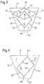
- FIGS. 2, 3 and 4each show diagrammatically a side view of a stent matrix with four zig-zag stenting rings, wherein
- FIG. 2reveals the at-rest, relaxed disposition of the self-expanding stent
- FIG. 3shows the same stent under pressure from bodily tissue to bend it out of a straight line
- FIG. 4shows the same stent, strained, in response to changes of radially-inward force on the stent from surrounding bodily tissue, along the length direction of the stent.
- FIG. 5shows schematically in transverse cross-section three different stent matrix connector strut shapes
- FIG. 6is a transverse cross-section like that of FIG. 5 , but showing an “asymmetric” connector strut cross-section.
- FIG. 1the skilled reader will recognise portions of two adjacent zig-zag stenting rings 2 , 4 and a single connector 6 of those two adjacent rings, central in the drawing Figure.
- That connector 6shows a serpentine form, resembling the letter “S” lying on its side and with the base of the letter S contiguous with one of the two zig-zag stenting rings 2 , 4 and the top of the letter S contiguous with the other of the two stenting rings.
- the serpentine form of the connector 6provides the stent matrix with capacity to undergo strain, somewhat additional to the capacity it would have if the serpentine connector 6 were to be replaced by a short straight link connecting the two zig-zag stenting rings 2 , 4 .
- FIG. 2we see diagrammatically a stent 10 composed of four zig-zag stenting rings 14 , 16 , 18 and 20 like the zig-zag rings shown in FIG. 1 .
- the longitudinal straight lines 22 and 24indicate the general form of the annulus of the stent.
- FIG. 3we can recognize that the annular stent matrix has undergone some strain, especially in the connector struts (not shown) between zig-zag ring 16 and zig-zag ring 18 and in the struts next to these connector portions.
- the stenthas sufficient flexibility to continue in the FIG. 3 disposition to deliver radially outwardly resistive force, even while it is bent into the arcuate shape of FIG. 3 , away from the relatively more relaxed straight disposition of FIG. 2 .
- One way to achieve good increases in bending flexibility without sacrificing much radial force delivered by the stent matrixwould be to reduce the wall thickness of portions of the stenting ring struts immediately adjacent to the ring connector portions.
- FIG. 4represents a situation in which the lumen in which the stent has been placed exerts a greater radially inward compressive force on zig-zag stenting rings 14 and 16 than on rings 18 and 20 .
- connector struts between zig-zag rings 16 and 18suffer shear stresses which would bend them into a lazy S-shape such as is apparent from FIG. 4 .
- the connector portions of the stent matrixshould exhibit enough flexibility in the zone between stenting ring 16 and 18 to permit the stent to take up a disposition as shown in FIG. 4 , at positions 30 and 32 . For this, one needs a significant degree of flexibility in the connectors linking stenting loops 16 and 18 .
- FIGS. 5 and 6We turn now to FIGS. 5 and 6 to reveal how such flexibility can be provided.
- FIG. 5a cross-section of a known connector strut T is shown with connector struts R, S of reduced cross-section overlaying it.
- the connector struts R and Sare exemplary embodiments of the present invention.
- the reduced cross-sectionprovides flexibility, as is explained below.
- FIG. 5shows two examples, marked R and S, of such connector struts, in cross-section.
- the connector strut section Ris bounded by four cut-lines of the off-axis laser, namely, lines 60 , 62 , 64 and 66 .
- This strut cross-sectionis truly a diamond rather than a sector of an annulus.
- Cross-section Sis another possibility, with off-axis laser cut-lines 70 , 72 , 74 and 76 .
- these connector strut cross-sectionsare symmetrical about a plane that extends through the longitudinal axis of the annulus of the workpiece, and the luminal apex 68 where cut-lines 64 and 66 intersect, and the abluminal apex 69 where cut-lines 60 and 62 intersect.
- the luminal apexis marked 78 and the abluminal apex is marked 80 .
- the luminal apex 68 , 78is further away from the longitudinal axis of the annulus than the luminal surface of the workpiece, and the abluminal apex 69 , 80 is closer to the longitudinal axis than the abluminal surface of the annular workpiece.
- a reduction in the radial thicknesshas a particularly strong contribution to increasing flexibility. The flatter of the two connector struts marked S may, therefore, be more advantageous if flexibility is key.
- FIG. 6we start with the same sector of the same annular workpiece, referenced with the same numbers, but show within it an asymmetric connector cross-section Q defined by laser cut-lines 90 , 92 , 94 and 96 .
- the intersection of cut-lines 94 and 96produces a luminal apex 98 and the intersection of cut-lines 90 and 92 is at an abluminal apex 99 .
- the plane that extends through these two apices 98 and 99when extended radially inwardly, does not pass through the longitudinal axis of the annular workpiece.
- stent technologyOne distinctive aspect of stent technology is how the strut matrix responds to expansion from a radially compact transluminal delivery disposition to a radially expanded deployed disposition.
- zig-zags in the compact dispositionare linear struts separated by slits, with the slits and struts all lined up with the long axis of the stent whereas, in the deployed position, the zig-zag rings have opened out as shown in each of FIGS. 1 to 4 .
- interestingis how stresses are distributed during the process of expansion from the delivery to the deployed disposition. The reader will appreciate that use of an asymmetric connector form such as shown in FIG.
- FIG. 6might yield a useful performance enhancement, in bringing peaks and valleys of zig-zag stenting rings into opposition, as opposed to a less attractive “peak-to-peak” design such as is apparent from FIG. 1 .
- peaks (points of inflection) of adjacent zig-zag stenting ringsare facing each other, with the consequence that these peaks are liable to impinge on each other when a deployed stent is forced into an arcuate configuration such as is evident from FIG. 3 , on the inside of the bend, at position 28 .
- use of an asymmetric cross-section connectoras shown in FIG.
- Stents for the carotid arteryis an example. Control is achieved by use of closed cell matrix structures, with a small mesh size and a relatively large number of connectors between adjacent stenting turns. An increasing number of connector struts reduces stent flexibility. The present invention offers a way to mitigate the flexibility problem without reducing the number of connector struts and thus can be particularly helpful in such applications.
- the method of manufacturetakes an appropriately sized tubular workpiece. Stenting turns are cut from this workpiece using a laser in the conventional way. That is, the laser beam follows a predetermined design pattern to form stenting struts to produce the stenting turns. In producing the stenting struts, the laser beam will be aimed to pass through the longitudinal axis of the tubular workpiece.
- the connector strutsare cut by aiming the laser beam in an offset manner from the longitudinal axis of the workpiece. The cut is such that the radial wall thickness is reduced as compared to the radial wall thickness of the stenting struts. This may be achieved as in embodiments discussed above by creating a luminal or abluminal apex.
- the zig-zag strutsmay include a repeating pattern made of a unit of four generally linear members that extend oblique to the longitudinal axis to intersect each other at three apices spaced apart circumferentially and axially.
- the prosthesiscan utilize not only the circumferential bridges but also other bridge configurations in combination.
- the bridgedirectly connects a peak of one circumferential section to another peak of an adjacent circumferential section.
- the bridgemay connect a peak of one circumferential section to a trough of an adjacent circumferential section.
- the bridgecan connect a trough of one circumferential section to a trough of an adjacent circumferential section.
- the undulationscan be wave-like in pattern.
- the wave-like patterncan also be generally sinusoidal in that the pattern may have the general form of a sine wave, whether or not such wave can be defined by a mathematical function.
- any wave-like formscan be employed so long as it has amplitude and displacement.
- the term “implantable prosthesis”is intended to cover not only a bare stent but also coated, covered, encapsulated, bio-resorbable stent or any portion of similar stents.
- Bio-active agentscan be added to the prosthesis (e.g., either by a coating or via a carrier medium such as resorbable polymers) for delivery to the host's vessel or duct.
- the bio-active agentsmay also be used to coat the entire stent.
- a material forming the stent or coupled to the stentmay include one or more (a) non-genetic therapeutic agents, (b) genetic materials, (c) cells and combinations thereof with (d) other polymeric materials.
- Non-genetic therapeutic agentsinclude anti-thrombogenic agents such as heparin, heparin derivatives, urokinase, and PPack (dextrophenylalanine proline arginine chloromethylketone); anti-proliferative agents such as enoxaprin, angiopeptin, or monoclonal antibodies capable of blocking smooth muscle cell proliferation, hirudin, and acetylsalicylic acid; anti-inflammatory agents such as dexamethasone, prednisolone, corticosterone, budesonide, estrogen, sulfasalazine, and mesalamine; antineoplastic/antiproliferative/anti-miotic agents such as paclitaxel, 5-fluorouracil, cisplatin, vinblastine, vincristine, epothilones, endostatin, angiostatin and thymidine kinase inhibitors; anesthetic agents such as lidocaine,
- Genetic materialsinclude anti-sense DNA and RNA, DNA coding for, anti-sense RNA, tRNA or rRNA to replace defective or deficient endogenous molecules, angiogenic factors including growth factors such as acidic and basic fibroblast growth factors, vascular endothelial growth factor epidermal growth factor, transforming growth factor alpha and beta, platelet-derived endothelial growth factor, platelet-derived growth factor, tumor necrosis factor alpha, hepatocyte growth factor and insulin like growth factor, cell cycle inhibitors including CD inhibitors, thymidine kinase (“TK”) and other agents useful for interfering with cell proliferation the family of bone morphogenic proteins (“BMPrs”), BlVfiP-2, BMP-3, BMP-4, BMP-5, BMP-6 (Vgr-1), BMP-7 (0P-1), BMP-8, BMP-9, BMP-10, BMP-1, BMP-12, BMP-13, BMP-14, BMP-15, and BMP-16.
- growth factorssuch as acidic
- Desirable BMP'sare any of BMP-2, BMP-3, BMP-4, BMP-5, BMP-6 and BMP-7. These dimeric proteins can be provided as homodimers, heterodimers, or combinations thereof, alone or together with other molecules. Alternatively or, in addition, molecules capable of inducing an upstream or downstream effect of a BMP can be provided. Such molecules include any of the “hedgehog” proteins, or the DNA's encoding them.
- Cellscan be of human origin (autologous or allogeneic) or from an animal source (xenogeneic), genetically engineered if desired to deliver proteins of interest at the deployment site.
- the cellsmay be provided in a delivery media.
- the delivery mediamay be formulated as needed to maintain cell function and viability.
- Suitable polymer materials as a coating or the base materialmay include polycarboxylic acids, cellulosic polymers, including cellulose acetate and cellulose nitrate, gelatin, polyvinylpyrrolidone, cross-linked polyvinylpyrrolidone, polyanhydrides including maleic anhydride polymers, polyamides, polyvinyl alcohols, copolymers of vinyl monomers such as EVA, polyvinyl ethers, polyvinyl aromatics, polyethylene oxides, glycosaminoglycans, polysaccharides, polyesters including polyethylene terephthalate, polyacrylamides, polyethers, polyether sulfone, polycarbonate, polyalkylenes including polypropylene, polyethylene and high molecular weight polyethylene, halogenated polyalkylenes including polytetrafluoroethylene, polyurethanes, polyorthoesters, proteins, polypeptides, silicones, siloxane polymers, polylactic acid, polyg
- Polyacrylic acidavailable as HYDROPLUS (Boston Scientific Corporation, Natick, Mass.), and described in U.S. Pat. No. 5,091,205, the disclosure of which is hereby incorporated herein by reference, is particularly desirable. Even more desirable is a copolymer of polylactic acid and polycaprolactone.
Landscapes
- Health & Medical Sciences (AREA)
- Engineering & Computer Science (AREA)
- Biomedical Technology (AREA)
- Optics & Photonics (AREA)
- Physics & Mathematics (AREA)
- Heart & Thoracic Surgery (AREA)
- Life Sciences & Earth Sciences (AREA)
- Cardiology (AREA)
- Oral & Maxillofacial Surgery (AREA)
- Transplantation (AREA)
- Veterinary Medicine (AREA)
- Vascular Medicine (AREA)
- Public Health (AREA)
- Animal Behavior & Ethology (AREA)
- General Health & Medical Sciences (AREA)
- Mechanical Engineering (AREA)
- Plasma & Fusion (AREA)
- Prostheses (AREA)
- Media Introduction/Drainage Providing Device (AREA)
- Laser Beam Processing (AREA)
Abstract
Description
This application is a continuation of U.S. patent application Ser. No. 14/793,648, filed Jul. 7, 2015, which is a continuation of U.S. patent application Ser. No. 14/045,603, filed Oct. 3, 2013, now U.S. Pat. No. 9,084,691, which is a division of U.S. patent application Ser. No. 12/514,177, filed May 8, 2009, now U.S. Pat. No. 8,551,156, which was filed as a U.S. national stage application under 35 USC § 371 of International Application No. PCT/EP2007/062155, filed Nov. 9, 2007, which claims priority to U.K. Patent Application No. 0622465.3, filed Nov. 10, 2006, each of which is incorporated by reference in its entirety into this application.
This invention relates to a radially-expansible annular stent comprising a plurality of stenting turns around a lumen centered on a longitudinal axis, with adjacent turns being joined by connector struts, the stent annulus having a wall thickness that is related to the material of which it is formed.
In the field of radially expansible annular stents that are called upon, in use, to resist a radially inwardly directed force from surrounding bodily tissue, in order to maintain a bodily lumen patent, there is a contradictory design requirement. On the one hand, the stent must be strong enough to keep the lumen patent. On the other hand, the stent prosthesis must be flexible enough to accommodate movement of surrounding bodily tissue.
There are two archetypal stent forms. One of them has a stack of closed loop stenting rings, the length direction of the stent being along the length of the longitudinal axis of the annulus of the stent. The other archetype is the helical stent, in which the pattern of struts in the stent matrix performs a spiral path around the longitudinal axis, to create an annulus from one end of the stent to the other. Typically, each of the stenting loops is composed of closed periphery repeating unit cells. See e.g., EP 0481365, FIG. 2. Typically, there are connector struts present, periodically through the annular matrix, to set the longitudinal spacing between adjacent stenting loops. See e.g., WO 1994/017754.
Such a stent is typically made from a seamless straight tubular workpiece so that its disposition, at rest, and relaxed, is that of a tubular cylindrical annulus. Typically, after implantation in the body, it is called upon to conform to an arcuate configuration of the bodily lumen in which it is placed. Such a change of shape necessitates the occurrence of strain within the matrix. That strain might not be homogeneously distributed throughout the matrix. Important for flexibility of the stent, after placement in the body, is a capacity for tolerating enough strain to give the stent, as such, enough flexibility to move with the body.
Another aspect of flexibility that is desirable when placing a stent is “radial conformability” by which is meant the ease with which succeeding turns of the stent can take or, after placement in tissue, different diameters clearly, when the struts connecting adjacent stenting rings have enhanced flexibility, an increase of radial conformability is in prospect.
Closed periphery unit cells of the stenting matrix are inherently rather well-adapted to provide the required resistance to the radially inwardly pressing force of the bodily tissue. In consequence, it is desirable for any connectors of unit cells, within the matrix, to deliver at least a substantial portion of the strain needed to allow the stent matrix to move with the body. Such flexibility in the connector links is not detrimental to the capability of the stenting loops to push the bodily tissue radially outwardly. For this reason, current stent designs often exhibit unit cells with simple straight strut peripheral portions, connected by connector struts that are not short and straight but long and thin. They are often meandering or arcuate or serpentine. There is discussed below, with reference toFIG. 1 , showing an exemplary stent having connector struts of the serpentine kind. This extra length provides the connectors with increased capacity to absorb strain and deliver flexibility to the stent, as such. However, building a stent annulus with convoluted or serpentine connectors adds to the complexity of manufacture and might not assist in meeting other government regulatory or quality control requirements.
It is an object of the present invention to ameliorate these difficulties.
According to the present invention, a stent as identified above is improved by arranging that, for the connector struts, the thickness of the struts is smaller than the ambient wall thickness of the stent.
Typically, stents are made from a seamless tubular workpiece of constant wall thickness. The description which follows will provide at least one way to produce a stent in accordance with the present invention from a seamless tubular workpiece of constant wall thickness.
Nickel-titanium shape memory alloy is a popular material from which to build self-expanding transluminally delivered bodily prostheses such as stents. Typically, they are made from the tubular workpiece by computer controlled laser cutting of slits in the workpiece, thereby to produce a matrix of struts. An attractive way to build stents in accordance with the present invention is by use of this laser cutting technique, known per se.
The conventional laser cutting process for making stents is with a laser beam arranged on a line that extends through the longitudinal axis of the stent annulus. However, the state of the art does include proposals, not only from the present applicant in WO 03/075797, WO 2006/010636 and WO 2006/010638 but also from others, such as Langhans et al in US 2006/0064153, to orient the laser beam on a line that does not pass through the longitudinal axis of the annulus. It is this step which is relied upon, in the presently preferred embodiment and best mode known to the inventor, as described in detail below. The concept can be conveniently designated “off-axis cutting”.
As will be seen below, an attractive feature of using off-axis laser cutting of the connectors is that one can provide the connectors with a transverse cross-section that is in some way asymmetric in comparison with a “conventional” on-axis laser-cut strut. Thus, the connectors in accordance with the present invention may have a transverse cross-section that includes a luminal apex at the intersection of two straight lines, that apex being the closest approach of the connector to the longitudinal axis. It can also create a connector having a transverse cross-section that includes an abluminal apex at the intersection of two straight lines, the apex being the point on the connector furthest away from the longitudinal axis. Such cross-sections through the connector can reveal a lack of mirror symmetry about a plane that includes the length direction of the connector and the longitudinal axis of the stent annulus. In other words, we can have a connector in which the transverse cross-section reveals a luminal apex and an abluminal apex, and the line passing through both of these apices does not also pass through the longitudinal axis of the annulus of the stent.
As will be seen below, an attractive feature of the present invention is that it enables the creation of stent matrices that combine good radial force against bodily tissue with good flexibility both in the radially expanded and in the radially compressed dispositions in a design in which the connectors are simple, short, substantially straight struts.
The stiffness of a strut of a stent matrix is proportional to the strut width but, in relation to the strut thickness, it goes up with the cube of the thickness. A small reduction of strut thickness can therefore yield large gains in flexibility. This property is utilised in the present invention by providing connector struts with a smaller radial wall thickness than that of the stent annulus.
For a better understanding of the present invention and to show more clearly how the same may be carried into effect, reference will now be made, by way of example, to the accompanying drawings. These are incorporated herein and constitute part of this specification. They illustrate presently preferred embodiments of the invention and, together with the general description above, and the detailed description below, serve to explain the features of the invention.
Looking first atFIG. 1 , the skilled reader will recognise portions of two adjacent zig-zag stenting rings2,4 and asingle connector 6 of those two adjacent rings, central in the drawing Figure. Thatconnector 6 shows a serpentine form, resembling the letter “S” lying on its side and with the base of the letter S contiguous with one of the two zig-zag stenting rings2,4 and the top of the letter S contiguous with the other of the two stenting rings. Self-evidently, the serpentine form of theconnector 6 provides the stent matrix with capacity to undergo strain, somewhat additional to the capacity it would have if theserpentine connector 6 were to be replaced by a short straight link connecting the two zig-zag stenting rings2,4.
Turning toFIG. 2 , we see diagrammatically astent 10 composed of four zig-zag stenting rings14,16,18 and20 like the zig-zag rings shown inFIG. 1 . The longitudinalstraight lines FIG. 3 , we can recognize that the annular stent matrix has undergone some strain, especially in the connector struts (not shown) between zig-zag ring 16 and zig-zag ring 18 and in the struts next to these connector portions. On the outside of the bend, atposition 26, the tensile strain is accommodated by bending of the struts and, on the inside of the bend, atposition 28, compressive stresses are likewise accommodated by bending of the struts. Ideally, the stent has sufficient flexibility to continue in theFIG. 3 disposition to deliver radially outwardly resistive force, even while it is bent into the arcuate shape ofFIG. 3 , away from the relatively more relaxed straight disposition ofFIG. 2 . One way to achieve good increases in bending flexibility without sacrificing much radial force delivered by the stent matrix would be to reduce the wall thickness of portions of the stenting ring struts immediately adjacent to the ring connector portions.
We turn now toFIGS. 5 and 6 to reveal how such flexibility can be provided.
Looking first atFIG. 5 , a cross-section of a known connector strut T is shown with connector struts R, S of reduced cross-section overlaying it. The connector struts R and S are exemplary embodiments of the present invention. The reduced cross-section provides flexibility, as is explained below.
It is important to grasp that the drawing is schematic. A moment's thought from the reader will reveal that the trapezium T withsides Sides straight line 50 ought to be arcuate, being a portion of the luminal wall of the cylindrical lumen defined by the annular workpiece. Likewise,straight line 54 ought to be an arc of a circle with a somewhat larger radius than that of the luminal surface of the annular workpiece, to correspond with a portion of the abluminal surface of that workpiece.
However, showingsides
Readers will know that, when laser cutting an annular workpiece, with the beam of the laser on the axis of the annulus, planar flat surfaces, represented bylines
However, once the possibility is taken up, to orient the laser beam “off-axis” so that the beam direction does not pass through the longitudinal axis of the annular workpiece and instead passes through a lumen of the workpiece, but offset from the longitudinal axis, then connector portions or strut cross-sections that are much smaller in area can readily be produced.FIG. 5 shows two examples, marked R and S, of such connector struts, in cross-section.
The connector strut section R is bounded by four cut-lines of the off-axis laser, namely, lines60,62,64 and66. This strut cross-section is truly a diamond rather than a sector of an annulus. Cross-section S is another possibility, with off-axis laser cut-lines
In both cases, these connector strut cross-sections are symmetrical about a plane that extends through the longitudinal axis of the annulus of the workpiece, and theluminal apex 68 where cut-lines lines luminal apex abluminal apex
Finally, turning toFIG. 6 , we start with the same sector of the same annular workpiece, referenced with the same numbers, but show within it an asymmetric connector cross-section Q defined by laser cut-lines FIG. 5 , the intersection of cut-lines luminal apex 98 and the intersection of cut-lines abluminal apex 99. However, the plane that extends through these twoapices
One distinctive aspect of stent technology is how the strut matrix responds to expansion from a radially compact transluminal delivery disposition to a radially expanded deployed disposition. Reverting back toFIGS. 1 to 4 , zig-zags in the compact disposition are linear struts separated by slits, with the slits and struts all lined up with the long axis of the stent whereas, in the deployed position, the zig-zag rings have opened out as shown in each ofFIGS. 1 to 4 . Interesting is how stresses are distributed during the process of expansion from the delivery to the deployed disposition. The reader will appreciate that use of an asymmetric connector form such as shown inFIG. 6 might yield a useful performance enhancement, in bringing peaks and valleys of zig-zag stenting rings into opposition, as opposed to a less attractive “peak-to-peak” design such as is apparent fromFIG. 1 . InFIG. 1 , peaks (points of inflection) of adjacent zig-zag stenting rings are facing each other, with the consequence that these peaks are liable to impinge on each other when a deployed stent is forced into an arcuate configuration such as is evident fromFIG. 3 , on the inside of the bend, atposition 28. By contrast, use of an asymmetric cross-section connector as shown inFIG. 6 , offers the potential to “skew” the stresses undergone by the stent matrix, when expanding into the deployed configuration, to such an extent as to displace facing peaks of the zig-zag rings circumferentially with respect to each other, by just enough to carry each peak into a position between two facing peaks of the next adjacent zig-zag stenting ring, the better able to accommodate strain on the inside of a bend such as atposition 28 inFIG. 3 .
In some applications of stents, a high degree of plaque control is called for. Stents for the carotid artery is an example. Control is achieved by use of closed cell matrix structures, with a small mesh size and a relatively large number of connectors between adjacent stenting turns. An increasing number of connector struts reduces stent flexibility. The present invention offers a way to mitigate the flexibility problem without reducing the number of connector struts and thus can be particularly helpful in such applications.
The method of manufacture takes an appropriately sized tubular workpiece. Stenting turns are cut from this workpiece using a laser in the conventional way. That is, the laser beam follows a predetermined design pattern to form stenting struts to produce the stenting turns. In producing the stenting struts, the laser beam will be aimed to pass through the longitudinal axis of the tubular workpiece. The connector struts are cut by aiming the laser beam in an offset manner from the longitudinal axis of the workpiece. The cut is such that the radial wall thickness is reduced as compared to the radial wall thickness of the stenting struts. This may be achieved as in embodiments discussed above by creating a luminal or abluminal apex.
Readers of this specification are persons skilled in the art of stent design, who will find many other embodiments, once given the concept of the present invention in the description above. The description above is exemplary, but not limiting.
Where undulations are embodied in the form of zig-zag struts, the zig-zag struts may include a repeating pattern made of a unit of four generally linear members that extend oblique to the longitudinal axis to intersect each other at three apices spaced apart circumferentially and axially. Also, the prosthesis can utilize not only the circumferential bridges but also other bridge configurations in combination. Alternatively, the bridge directly connects a peak of one circumferential section to another peak of an adjacent circumferential section. In yet another alternative, the bridge may connect a peak of one circumferential section to a trough of an adjacent circumferential section. In a further alternative, the bridge can connect a trough of one circumferential section to a trough of an adjacent circumferential section. Moreover, the undulations can be wave-like in pattern. The wave-like pattern can also be generally sinusoidal in that the pattern may have the general form of a sine wave, whether or not such wave can be defined by a mathematical function. Alternatively, any wave-like forms can be employed so long as it has amplitude and displacement. For example, a square wave, saw tooth wave, or any applicable wave-like pattern defined by the struts where the struts have substantially equal lengths or unequal lengths. And as used herein, the term “implantable prosthesis” is intended to cover not only a bare stent but also coated, covered, encapsulated, bio-resorbable stent or any portion of similar stents.
Bio-active agents can be added to the prosthesis (e.g., either by a coating or via a carrier medium such as resorbable polymers) for delivery to the host's vessel or duct. The bio-active agents may also be used to coat the entire stent. A material forming the stent or coupled to the stent may include one or more (a) non-genetic therapeutic agents, (b) genetic materials, (c) cells and combinations thereof with (d) other polymeric materials.
(a) Non-genetic therapeutic agents include anti-thrombogenic agents such as heparin, heparin derivatives, urokinase, and PPack (dextrophenylalanine proline arginine chloromethylketone); anti-proliferative agents such as enoxaprin, angiopeptin, or monoclonal antibodies capable of blocking smooth muscle cell proliferation, hirudin, and acetylsalicylic acid; anti-inflammatory agents such as dexamethasone, prednisolone, corticosterone, budesonide, estrogen, sulfasalazine, and mesalamine; antineoplastic/antiproliferative/anti-miotic agents such as paclitaxel, 5-fluorouracil, cisplatin, vinblastine, vincristine, epothilones, endostatin, angiostatin and thymidine kinase inhibitors; anesthetic agents such as lidocaine, bupivacaine, and ropivacaine; anti-coagulants, an RGD peptide-containing compound, heparin, antithrombin compounds, platelet receptor antagonists, anti-thrombin antibodies, anti-platelet receptor antibodies, aspirin, prostaglandin inhibitors, platelet inhibitors and tick antiplatelet peptides; vascular cell growth promoters such as growth factor inhibitors, growth factor receptor antagonists, transcriptional activators, and translational promoters; vascular cell growth inhibitors such as growth factor inhibitors, growth factor receptor antagonists, transcriptional repressors, translational repressors, replication inhibitors, inhibitory antibodies, antibodies directed against growth factors, bifunctional molecules consisting of a growth factor and a cytotoxin, bifunctional molecules consisting of an antibody and a cytotoxin; cholesterol-lowering agents; vasodilating agents; and agents which interfere with endogenous vascoactive mechanisms.
(b) Genetic materials include anti-sense DNA and RNA, DNA coding for, anti-sense RNA, tRNA or rRNA to replace defective or deficient endogenous molecules, angiogenic factors including growth factors such as acidic and basic fibroblast growth factors, vascular endothelial growth factor epidermal growth factor, transforming growth factor alpha and beta, platelet-derived endothelial growth factor, platelet-derived growth factor, tumor necrosis factor alpha, hepatocyte growth factor and insulin like growth factor, cell cycle inhibitors including CD inhibitors, thymidine kinase (“TK”) and other agents useful for interfering with cell proliferation the family of bone morphogenic proteins (“BMPrs”), BlVfiP-2, BMP-3, BMP-4, BMP-5, BMP-6 (Vgr-1), BMP-7 (0P-1), BMP-8, BMP-9, BMP-10, BMP-1, BMP-12, BMP-13, BMP-14, BMP-15, and BMP-16. Desirable BMP's are any of BMP-2, BMP-3, BMP-4, BMP-5, BMP-6 and BMP-7. These dimeric proteins can be provided as homodimers, heterodimers, or combinations thereof, alone or together with other molecules. Alternatively or, in addition, molecules capable of inducing an upstream or downstream effect of a BMP can be provided. Such molecules include any of the “hedgehog” proteins, or the DNA's encoding them.
(c) Cells can be of human origin (autologous or allogeneic) or from an animal source (xenogeneic), genetically engineered if desired to deliver proteins of interest at the deployment site. The cells may be provided in a delivery media. The delivery media may be formulated as needed to maintain cell function and viability.
(d) Suitable polymer materials as a coating or the base material may include polycarboxylic acids, cellulosic polymers, including cellulose acetate and cellulose nitrate, gelatin, polyvinylpyrrolidone, cross-linked polyvinylpyrrolidone, polyanhydrides including maleic anhydride polymers, polyamides, polyvinyl alcohols, copolymers of vinyl monomers such as EVA, polyvinyl ethers, polyvinyl aromatics, polyethylene oxides, glycosaminoglycans, polysaccharides, polyesters including polyethylene terephthalate, polyacrylamides, polyethers, polyether sulfone, polycarbonate, polyalkylenes including polypropylene, polyethylene and high molecular weight polyethylene, halogenated polyalkylenes including polytetrafluoroethylene, polyurethanes, polyorthoesters, proteins, polypeptides, silicones, siloxane polymers, polylactic acid, polyglycolic acid, polycaprolactone, polyhydroxybutyrate valerate and blends and copolymers thereof, coatings from polymer dispersions such as polyurethane dispersions (for example, BAYHDROL fibrin, collagen and derivatives thereof, polysaccharides such as celluloses, starches, dextrans, alginates and derivatives, hyaluronic acid, squalene emulsions. Polyacrylic acid, available as HYDROPLUS (Boston Scientific Corporation, Natick, Mass.), and described in U.S. Pat. No. 5,091,205, the disclosure of which is hereby incorporated herein by reference, is particularly desirable. Even more desirable is a copolymer of polylactic acid and polycaprolactone.
While the invention has been described in terms of particular variations and illustrative figures, those of ordinary skill in the art will recognize that the invention is not limited to the variations or figures described. The method used in the present invention is not limited to the preferred method discussed above, as will be apparent from the claims. Further, the improved flexibility of the stents of the present invention may be achieved by methods other than the preferred one given above, as will be apparent to the skilled person. In addition, where methods and steps described above indicate certain events occurring in certain order, those of ordinary skill in the art will recognize that the ordering of certain steps may be modified and that such modifications are in accordance with the variations of the invention. Additionally, certain of the steps may be performed concurrently in a parallel process when possible, as well as performed sequentially as described above. Therefore, to the extent there are variations of the invention, which are within the spirit of the disclosure or equivalent to the inventions found in the claims, it is the intent that this patent will cover those variations as well. Finally, all publications and patent applications cited in this specification are herein incorporated by reference in their entirety as if each individual publication or patent application were specifically and individually put forth herein.
Claims (5)
1. A method of making a stent having a plurality of turns around a longitudinal axis comprising:
cutting a tubular workpiece with a beam to form a connector strut having a thickness less than a wall thickness of the tubular workpiece, wherein:
the beam does not intersect the longitudinal axis,
a first turn portion immediately adjacent to the connector strut has a thickness less than the wall thickness of the tubular workpiece,
a second turn portion has a thickness greater than the first turn portion,
the connector strut comprises cut surfaces that intersect to form a luminal angle at a luminal point further from the longitudinal axis than a luminal workpiece surface,
the connector strut comprises cut surfaces that intersect to form an abluminal angle at an abluminal point closer to the longitudinal axis than an abluminal workpiece surface, and
a transverse connector strut cross-section does not have a mirror symmetry plane containing the longitudinal axis.
2. The method ofclaim 1 , further comprising cutting the tubular workpiece with the beam to form a turn comprising two or more stenting struts, wherein the beam intersects the longitudinal axis.
3. The method ofclaim 1 , wherein the connector strut joins adjacent turn portions.
4. The method ofclaim 1 , wherein an inflection point is disposed between at least two stenting struts.
5. The method ofclaim 1 , wherein a plane that extends through the luminal point and the abluminal point is parallel to the longitudinal axis.
Priority Applications (1)
| Application Number | Priority Date | Filing Date | Title |
|---|---|---|---|
| US15/436,634US10500075B2 (en) | 2006-11-10 | 2017-02-17 | Stent |
Applications Claiming Priority (7)
| Application Number | Priority Date | Filing Date | Title |
|---|---|---|---|
| GB0622465.3 | 2006-11-10 | ||
| GBGB0622465.3AGB0622465D0 (en) | 2006-11-10 | 2006-11-10 | Stent |
| PCT/EP2007/062155WO2008055980A1 (en) | 2006-11-10 | 2007-11-09 | Stent |
| US51417709A | 2009-05-08 | 2009-05-08 | |
| US14/045,603US9084691B2 (en) | 2006-11-10 | 2013-10-03 | Stent |
| US14/793,648US9872783B2 (en) | 2006-11-10 | 2015-07-07 | Stent |
| US15/436,634US10500075B2 (en) | 2006-11-10 | 2017-02-17 | Stent |
Related Parent Applications (1)
| Application Number | Title | Priority Date | Filing Date |
|---|---|---|---|
| US14/793,648ContinuationUS9872783B2 (en) | 2006-11-10 | 2015-07-07 | Stent |
Publications (2)
| Publication Number | Publication Date |
|---|---|
| US20170156901A1 US20170156901A1 (en) | 2017-06-08 |
| US10500075B2true US10500075B2 (en) | 2019-12-10 |
Family
ID=37594714
Family Applications (4)
| Application Number | Title | Priority Date | Filing Date |
|---|---|---|---|
| US12/514,177Active2028-09-05US8551156B2 (en) | 2006-11-10 | 2007-11-09 | Stent |
| US14/045,603Active2027-11-13US9084691B2 (en) | 2006-11-10 | 2013-10-03 | Stent |
| US14/793,648ActiveUS9872783B2 (en) | 2006-11-10 | 2015-07-07 | Stent |
| US15/436,634Active2028-10-31US10500075B2 (en) | 2006-11-10 | 2017-02-17 | Stent |
Family Applications Before (3)
| Application Number | Title | Priority Date | Filing Date |
|---|---|---|---|
| US12/514,177Active2028-09-05US8551156B2 (en) | 2006-11-10 | 2007-11-09 | Stent |
| US14/045,603Active2027-11-13US9084691B2 (en) | 2006-11-10 | 2013-10-03 | Stent |
| US14/793,648ActiveUS9872783B2 (en) | 2006-11-10 | 2015-07-07 | Stent |
Country Status (4)
| Country | Link |
|---|---|
| US (4) | US8551156B2 (en) |
| EP (1) | EP2088972B1 (en) |
| GB (1) | GB0622465D0 (en) |
| WO (1) | WO2008055980A1 (en) |
Cited By (1)
| Publication number | Priority date | Publication date | Assignee | Title |
|---|---|---|---|---|
| US10849770B2 (en) | 2006-05-17 | 2020-12-01 | C. R. Bard, Inc. | Bend-capable tubular prosthesis |
Families Citing this family (25)
| Publication number | Priority date | Publication date | Assignee | Title |
|---|---|---|---|---|
| US6755856B2 (en) | 1998-09-05 | 2004-06-29 | Abbott Laboratories Vascular Enterprises Limited | Methods and apparatus for stenting comprising enhanced embolic protection, coupled with improved protection against restenosis and thrombus formation |
| GB0020491D0 (en) | 2000-08-18 | 2000-10-11 | Angiomed Ag | Stent with attached element and method of making such a stent |
| JP2009526572A (en)* | 2006-02-14 | 2009-07-23 | アンギオメット ゲゼルシャフト ミット ベシュレンクテル ハフツング ウント コムパニー メディツィンテヒニク コマンデイトゲゼルシャフト | Highly flexible stent and manufacturing method |
| GB0609911D0 (en) | 2006-05-18 | 2006-06-28 | Angiomed Ag | Bend-capable stent prosthesis |
| GB0616579D0 (en) | 2006-08-21 | 2006-09-27 | Angiomed Ag | Self-expanding stent |
| GB0616999D0 (en) | 2006-08-29 | 2006-10-04 | Angiomed Ag | Annular mesh |
| EP2063824B1 (en) | 2006-09-07 | 2020-10-28 | Angiomed GmbH & Co. Medizintechnik KG | Helical implant having different ends |
| GB0622465D0 (en) | 2006-11-10 | 2006-12-20 | Angiomed Ag | Stent |
| GB0624419D0 (en) | 2006-12-06 | 2007-01-17 | Angiomed Ag | Stenting ring with marker |
| GB0706499D0 (en) | 2007-04-03 | 2007-05-09 | Angiomed Ag | Bendable stent |
| US8128679B2 (en)* | 2007-05-23 | 2012-03-06 | Abbott Laboratories Vascular Enterprises Limited | Flexible stent with torque-absorbing connectors |
| GB0717481D0 (en) | 2007-09-07 | 2007-10-17 | Angiomed Ag | Self-expansible stent with radiopaque markers |
| US8328863B2 (en) | 2010-04-22 | 2012-12-11 | Abbott Cardiovascular Systems Inc. | Optimal ratio of polar and bending moment of inertia for stent strut design |
| WO2014117037A1 (en) | 2013-01-24 | 2014-07-31 | GraftWorx, LLC | Method and apparatus for measuring flow through a lumen |
| AU2014284216B2 (en) | 2013-06-21 | 2017-10-05 | Boston Scientific Scimed, Inc. | Stent with deflecting connector |
| US9924905B2 (en) | 2015-03-09 | 2018-03-27 | Graftworx, Inc. | Sensor position on a prosthesis for detection of a stenosis |
| EP3088095B1 (en)* | 2015-04-29 | 2019-07-17 | TRUMPF Werkzeugmaschinen GmbH + Co. KG | Method for processing panel-shaped workpieces |
| US10232082B2 (en) | 2015-06-29 | 2019-03-19 | 480 Biomedical, Inc. | Implantable scaffolds for treatment of sinusitis |
| EP3313330A4 (en) | 2015-06-29 | 2019-03-20 | 480 Biomedical, Inc. | SUPPORT LOADING AND DISTRIBUTION SYSTEMS |
| WO2017004268A1 (en) | 2015-06-29 | 2017-01-05 | 480 Biomedical, Inc. | Implantable scaffolds for treatment of sinusitis |
| US10973664B2 (en) | 2015-12-30 | 2021-04-13 | Lyra Therapeutics, Inc. | Scaffold loading and delivery systems |
| JP6821933B2 (en)* | 2016-03-24 | 2021-01-27 | カシオ計算機株式会社 | Electronic equipment, communication equipment, control methods, and programs |
| DE102016106577A1 (en)* | 2016-04-11 | 2017-10-12 | Biotronik Ag | Tubular intravascular implant |
| WO2018049412A1 (en) | 2016-09-12 | 2018-03-15 | Graftworx, Inc. | Wearable device with multimodal diagnostics |
| US10201639B2 (en) | 2017-05-01 | 2019-02-12 | 480 Biomedical, Inc. | Drug-eluting medical implants |
Citations (167)
| Publication number | Priority date | Publication date | Assignee | Title |
|---|---|---|---|---|
| GB453944A (en) | 1935-04-10 | 1936-09-22 | John Walter Anderson | Improvements in couplings for vehicles |
| US3749878A (en) | 1967-03-16 | 1973-07-31 | Nat Res Dev | Gas assisted laser cutting apparatus |
| US3943324A (en) | 1970-12-14 | 1976-03-09 | Arthur D. Little, Inc. | Apparatus for forming refractory tubing |
| FR2626046A1 (en) | 1988-01-18 | 1989-07-21 | Caoutchouc Manuf Plastique | Device for joining panels or for producing conduits and its applications |
| US5091205A (en) | 1989-01-17 | 1992-02-25 | Union Carbide Chemicals & Plastics Technology Corporation | Hydrophilic lubricious coatings |
| EP0481365A1 (en) | 1990-10-13 | 1992-04-22 | Angiomed Ag | Device for expanding a stenosis in a body duct |
| DE4130431A1 (en) | 1991-09-13 | 1993-03-18 | Liselotte Dr Sachse | Plastics urethral prosthesis - consists of tube and reinforced with metal rings placed in tube mould or fitted within plastics layers of tube |
| US5195984A (en) | 1988-10-04 | 1993-03-23 | Expandable Grafts Partnership | Expandable intraluminal graft |
| WO1994017754A1 (en) | 1993-02-04 | 1994-08-18 | Angiomed Ag | Stent |
| US5345057A (en) | 1993-03-25 | 1994-09-06 | Lasag Ag | Method of cutting an aperture in a device by means of a laser beam |
| WO1995003010A1 (en) | 1993-07-23 | 1995-02-02 | Cook Incorporated | A flexible stent having a pattern formed from a sheet of material |
| US5464419A (en) | 1993-03-22 | 1995-11-07 | Industrial Research B.V. | Expandable hollow sleeve for the local support and/or reinforcement of a body vessel, and method for the fabrication thereof |
| JPH07315147A (en) | 1994-05-23 | 1995-12-05 | Nishikawa Rubber Co Ltd | Drip weather strip mounting structure |
| EP0709068A2 (en) | 1994-10-27 | 1996-05-01 | Medinol Ltd. | X-ray visible stent |
| US5527353A (en) | 1993-12-02 | 1996-06-18 | Meadox Medicals, Inc. | Implantable tubular prosthesis |
| WO1996026689A1 (en) | 1995-03-01 | 1996-09-06 | Scimed Life Systems, Inc. | Improved longitudinally flexible expandable stent |
| US5591223A (en) | 1992-11-23 | 1997-01-07 | Children's Medical Center Corporation | Re-expandable endoprosthesis |
| DE29621207U1 (en) | 1996-12-06 | 1997-01-30 | MAN Roland Druckmaschinen AG, 63075 Offenbach | Fastening a heat sink on a printed circuit board |
| US5645532A (en) | 1996-03-04 | 1997-07-08 | Sil-Med Corporation | Radiopaque cuff peritoneal dialysis catheter |
| WO1997033534A1 (en) | 1996-03-13 | 1997-09-18 | Medtronic, Inc. | Radiopaque stent markers |
| EP0800800A1 (en) | 1996-04-10 | 1997-10-15 | Variomed AG | Stent for transluminal implantation in a hollow organ |
| US5725572A (en) | 1994-04-25 | 1998-03-10 | Advanced Cardiovascular Systems, Inc. | Radiopaque stent |
| US5741327A (en) | 1997-05-06 | 1998-04-21 | Global Therapeutics, Inc. | Surgical stent featuring radiopaque markers |
| WO1998020810A1 (en) | 1996-11-12 | 1998-05-22 | Medtronic, Inc. | Flexible, radially expansible luminal prostheses |
| US5759192A (en) | 1994-11-28 | 1998-06-02 | Advanced Cardiovascular Systems, Inc. | Method and apparatus for direct laser cutting of metal stents |
| EP0847733A1 (en) | 1996-12-10 | 1998-06-17 | BIOTRONIK Mess- und Therapiegeräte GmbH & Co Ingenieurbüro Berlin | Stent |
| US5800511A (en) | 1993-01-19 | 1998-09-01 | Schneider (Usa) Inc | Clad composite stent |
| EP0870483A2 (en) | 1997-03-14 | 1998-10-14 | Nozomu Kanesaka | Flexible stent |
| US5824059A (en)* | 1997-08-05 | 1998-10-20 | Wijay; Bandula | Flexible stent |
| US5824042A (en) | 1996-04-05 | 1998-10-20 | Medtronic, Inc. | Endoluminal prostheses having position indicating markers |
| US5843175A (en) | 1997-06-13 | 1998-12-01 | Global Therapeutics, Inc. | Enhanced flexibility surgical stent |
| US5843118A (en) | 1995-12-04 | 1998-12-01 | Target Therapeutics, Inc. | Fibered micro vaso-occlusive devices |
| DE19728337A1 (en) | 1997-07-03 | 1999-01-07 | Inst Mikrotechnik Mainz Gmbh | Implantable stent |
| US5858556A (en) | 1997-01-21 | 1999-01-12 | Uti Corporation | Multilayer composite tubular structure and method of making |
| US5868783A (en) | 1997-04-16 | 1999-02-09 | Numed, Inc. | Intravascular stent with limited axial shrinkage |
| US5876449A (en)* | 1995-04-01 | 1999-03-02 | Variomed Ag | Stent for the transluminal implantation in hollow organs |
| WO1999015108A2 (en) | 1997-09-24 | 1999-04-01 | Med Institute, Inc. | Radially expandable stent |
| DE29904817U1 (en) | 1999-03-16 | 1999-05-27 | amg Handelsgesellschaft für angewandte Medizin- und Gesundheitstechnik mbH, 46348 Raesfeld | Blood vessel support device |
| US5922020A (en) | 1996-08-02 | 1999-07-13 | Localmed, Inc. | Tubular prosthesis having improved expansion and imaging characteristics |
| WO1999038457A1 (en) | 1998-02-03 | 1999-08-05 | Jang G David | Tubular stent consisting of horizontal expansion struts and contralaterally attached diagonal-connectors |
| WO1999049928A1 (en) | 1998-03-30 | 1999-10-07 | Conor Medsystems, Inc. | Expandable medical device with ductile hinges |
| WO1999055253A1 (en) | 1998-04-27 | 1999-11-04 | Microval (S.A.R.L.) | Tubular and flexible vascular prosthesis |
| US6022374A (en) | 1997-12-16 | 2000-02-08 | Cardiovasc, Inc. | Expandable stent having radiopaque marker and method |
| US6053940A (en) | 1995-10-20 | 2000-04-25 | Wijay; Bandula | Vascular stent |
| US6056187A (en) | 1996-06-25 | 2000-05-02 | International Business Machines Corporation | Modular wire band stent |
| US6086611A (en) | 1997-09-25 | 2000-07-11 | Ave Connaught | Bifurcated stent |
| US6099561A (en) | 1996-10-21 | 2000-08-08 | Inflow Dynamics, Inc. | Vascular and endoluminal stents with improved coatings |
| WO2000045742A1 (en) | 1999-02-02 | 2000-08-10 | C.R. Bard, Inc. | Covered stent with encapsulated ends |
| EP1029517A2 (en) | 1999-01-14 | 2000-08-23 | Medtronic Inc. | Staggered endoluminal stent |
| WO2000049971A1 (en) | 1999-02-26 | 2000-08-31 | Advanced Cardiovascular Systems, Inc. | Stent with customized flexibility |
| EP1034751A2 (en) | 1999-03-05 | 2000-09-13 | Terumo Kabushiki Kaisha | Implanting stent and dilating device |
| WO2000064375A1 (en) | 1999-04-22 | 2000-11-02 | Advanced Cardiovascular Systems, Inc. | Radiopaque stents |
| WO2001001889A1 (en) | 1999-07-02 | 2001-01-11 | Scimed Life Systems, Inc. | Spiral wound stent |
| US6174329B1 (en) | 1996-08-22 | 2001-01-16 | Advanced Cardiovascular Systems, Inc. | Protective coating for a stent with intermediate radiopaque coating |
| WO2001032102A1 (en) | 1999-10-29 | 2001-05-10 | Angiomed Gmbh & Co. Medizintechnik Kg | Method of making a stent |
| WO2001058384A1 (en) | 2000-02-14 | 2001-08-16 | Angiomed Gmbh & Co. Medizintechnik Kg | Stent matrix |
| WO2001076508A2 (en) | 2000-04-12 | 2001-10-18 | Angiomed Gmbh & Co. Medizintechnik Kg | Self-expanding memory metal stent and method of making it |
| EP1157673A2 (en) | 2000-05-26 | 2001-11-28 | Variomed AG | Stent, position's element and delivery catheter |
| US6325825B1 (en) | 1999-04-08 | 2001-12-04 | Cordis Corporation | Stent with variable wall thickness |
| US20020007212A1 (en) | 1995-03-01 | 2002-01-17 | Brown Brian J. | Longitudinally flexible expandable stent |
| WO2002015820A2 (en) | 2000-08-18 | 2002-02-28 | Angiomed Gmbh & Co. Medizintechnik Kg | Implant with attached element and method of making such an implant |
| EP1190685A2 (en) | 2000-09-22 | 2002-03-27 | Cordis Corporation | Stent with optimal strength and radiopacity characteristics |
| US6379381B1 (en) | 1999-09-03 | 2002-04-30 | Advanced Cardiovascular Systems, Inc. | Porous prosthesis and a method of depositing substances into the pores |
| US6387123B1 (en) | 1999-10-13 | 2002-05-14 | Advanced Cardiovascular Systems, Inc. | Stent with radiopaque core |
| EP1212991A2 (en) | 2000-12-07 | 2002-06-12 | Cordis Corporation | An intravascular device with improved radiopacity |
| WO2002049544A1 (en) | 2000-12-19 | 2002-06-27 | Vascular Architects, Inc. | Biologically active agent delivery apparatus and method |
| US20020116051A1 (en) | 1992-02-21 | 2002-08-22 | Cragg Andrew H. | Intraluminal stent and graft |
| US20020116044A1 (en) | 2000-05-22 | 2002-08-22 | Cottone, Robert John | Self-expanding stent |
| US6451047B2 (en) | 1995-03-10 | 2002-09-17 | Impra, Inc. | Encapsulated intraluminal stent-graft and methods of making same |
| US20020138136A1 (en) | 2001-03-23 | 2002-09-26 | Scimed Life Systems, Inc. | Medical device having radio-opacification and barrier layers |
| EP1245203A2 (en) | 2001-03-30 | 2002-10-02 | Terumo Kabushiki Kaisha | Stent |
| US6471721B1 (en) | 1999-12-30 | 2002-10-29 | Advanced Cardiovascular Systems, Inc. | Vascular stent having increased radiopacity and method for making same |
| US6475233B2 (en) | 1997-04-08 | 2002-11-05 | Interventional Technologies, Inc. | Stent having tapered struts |
| US6478816B2 (en) | 1998-07-08 | 2002-11-12 | Scimed Life Systems, Inc. | Stent |
| US20020193867A1 (en) | 2001-06-19 | 2002-12-19 | Gladdish Bennie W. | Low profile improved radiopacity intraluminal medical device |
| US20020198589A1 (en)* | 2001-06-22 | 2002-12-26 | Leong Veronica Jade | Tessellated stent and method of manufacture |
| US20030055485A1 (en) | 2001-09-17 | 2003-03-20 | Intra Therapeutics, Inc. | Stent with offset cell geometry |
| US6540777B2 (en) | 2001-02-15 | 2003-04-01 | Scimed Life Systems, Inc. | Locking stent |
| US6547818B1 (en) | 2000-10-20 | 2003-04-15 | Endotex Interventional Systems, Inc. | Selectively thinned coiled-sheet stents and methods for making them |
| US6585757B1 (en) | 1999-09-15 | 2003-07-01 | Advanced Cardiovascular Systems, Inc. | Endovascular stent with radiopaque spine |
| WO2003055414A1 (en) | 2001-10-18 | 2003-07-10 | Advanced Stent Technologies, Inc. | Stent for vessel support, coverage and side branch accessibility |
| US20030135254A1 (en) | 1997-01-09 | 2003-07-17 | Maria Curcio | Stent for angioplasty and a production process therefor |
| DE10201151A1 (en) | 2002-01-15 | 2003-07-31 | Qualimed Innovative Med Prod | Surgical stent design of metal strut framework integrates marker between frame struts and of equal or lesser thickness than struts to identifiy stent position throughout service. |
| US20030144729A1 (en) | 2002-01-30 | 2003-07-31 | Scimed Life Systems, Inc. | Stent with wishbone connectors and serpentine bands |
| US6605110B2 (en)* | 2001-06-29 | 2003-08-12 | Advanced Cardiovascular Systems, Inc. | Stent with enhanced bendability and flexibility |
| WO2003075797A2 (en) | 2002-03-14 | 2003-09-18 | Angiomed Gmbh & Co. Medizintechnik Kg | Mri compatible stent and method of manufacturing the same_______ |
| US6629994B2 (en) | 2001-06-11 | 2003-10-07 | Advanced Cardiovascular Systems, Inc. | Intravascular stent |
| US20030216807A1 (en) | 2002-05-16 | 2003-11-20 | Jones Donald K. | Intravascular stent device |
| US6652572B2 (en)* | 1998-10-05 | 2003-11-25 | Cordis Corporation | Endovascular graft system |
| US20030225448A1 (en) | 2002-05-28 | 2003-12-04 | Scimed Life Systems, Inc. | Polar radiopaque marker for stent |
| US20040015229A1 (en) | 2002-07-22 | 2004-01-22 | Syntheon, Llc | Vascular stent with radiopaque markers |
| US20040034402A1 (en) | 2002-07-26 | 2004-02-19 | Syntheon, Llc | Helical stent having flexible transition zone |
| US20040044401A1 (en) | 2002-08-30 | 2004-03-04 | Bales Thomas O. | Helical stent having improved flexibility and expandability |
| WO2004019820A1 (en) | 2002-08-30 | 2004-03-11 | Advanced Cardiovascular Systems, Inc. | Stent with nested rings |
| US20040054400A1 (en) | 1999-11-12 | 2004-03-18 | Granada Vuan Fernando | Conformable vascular stent |
| WO2004028408A1 (en) | 2002-09-26 | 2004-04-08 | Cardiovasc, Inc. | Stent graft assembly with attached security rings and method of use |
| US20040073291A1 (en) | 2002-10-09 | 2004-04-15 | Brian Brown | Intraluminal medical device having improved visibility |
| US20040073290A1 (en) | 2002-10-09 | 2004-04-15 | Scimed Life Systems, Inc. | Stent with improved flexibility |
| US20040093072A1 (en) | 2002-05-06 | 2004-05-13 | Jeff Pappas | Endoprosthesis for controlled contraction and expansion |
| US20040093073A1 (en) | 2002-05-08 | 2004-05-13 | David Lowe | Endoprosthesis having foot extensions |
| US20040117002A1 (en) | 2002-12-16 | 2004-06-17 | Scimed Life Systems, Inc. | Flexible stent with improved axial strength |
| EP1433438A2 (en) | 1994-02-09 | 2004-06-30 | Boston Scientific Limited | Endoluminal prosthesis having radiopaque marker |
| WO2004058384A1 (en) | 2002-12-17 | 2004-07-15 | Fluor Corporation | Configurations and methods for acid gas and contaminant removal with near zero emission |
| US6770089B1 (en) | 2000-12-28 | 2004-08-03 | Advanced Cardiovascular Systems, Inc. | Hybrid stent fabrication using metal rings and polymeric links |
| US20040230293A1 (en) | 2003-05-15 | 2004-11-18 | Yip Philip S. | Intravascular stent |
| US20040236409A1 (en) | 2003-05-20 | 2004-11-25 | Pelton Alan R. | Radiopacity intraluminal medical device |
| US6827734B2 (en) | 1994-07-25 | 2004-12-07 | Advanced Cardiovascular Systems, Inc. | High strength member for intracorporeal use |
| US20040254637A1 (en) | 2003-06-16 | 2004-12-16 | Endotex Interventional Systems, Inc. | Sleeve stent marker |
| US20050010275A1 (en) | 2002-10-11 | 2005-01-13 | Sahatjian Ronald A. | Implantable medical devices |
| DE202004014789U1 (en) | 2004-09-22 | 2005-01-27 | Campus Medizin & Technik Gmbh | Stent for implantation into or onto a hollow organ comprises a cutout serving as receptacle for a conical marker element which is X-ray opaque and is oriented radially relative to the stent axis |
| US20050049682A1 (en) | 2003-05-23 | 2005-03-03 | Scimed Life Systems, Inc. | Stents with attached looped ends |
| US20050060025A1 (en) | 2003-09-12 | 2005-03-17 | Mackiewicz David A. | Radiopaque markers for medical devices |
| US6896696B2 (en) | 1998-11-20 | 2005-05-24 | Scimed Life Systems, Inc. | Flexible and expandable stent |
| US20050149168A1 (en) | 2003-12-30 | 2005-07-07 | Daniel Gregorich | Stent to be deployed on a bend |
| WO2005067816A1 (en) | 2004-01-12 | 2005-07-28 | Angiomed Gmbh & Co. Medizintechnik Kg | Mri compatible implant comprising electrically conductive closed loops |
| WO2005072652A1 (en) | 2004-01-27 | 2005-08-11 | Med Institute, Inc. | Anchoring barb for attachment to a medical prosthesis |
| US20050172471A1 (en) | 2004-02-09 | 2005-08-11 | Vietmeier Kristopher H. | Process method for attaching radio opaque markers to shape memory stent |
| US20050182477A1 (en) | 2001-12-20 | 2005-08-18 | White Geoffrey H. | Intraluminal stent and graft |
| US20050184277A1 (en) | 2004-02-19 | 2005-08-25 | Chung Shan Institute Of Science & Technology | Method for preparing arylphosphonite antioxidant |
| US20050222667A1 (en) | 2004-03-31 | 2005-10-06 | Hunt James B | Stent-graft with graft to graft attachment |
| WO2005104991A1 (en) | 2004-05-05 | 2005-11-10 | Invatec S.R.L. | Endoluminal prosthesis |
| US20050278019A1 (en) | 2004-06-09 | 2005-12-15 | Boston Scientific Scimed, Inc. | Overlapped stents for scaffolding, flexibility and MRI compatibility |
| US6979346B1 (en) | 2001-08-08 | 2005-12-27 | Advanced Cardiovascular Systems, Inc. | System and method for improved stent retention |
| WO2006010638A1 (en) | 2004-07-30 | 2006-02-02 | Angiomed Gmbh & Co. Medizintechnik Kg | Medical implant such as a stent |
| WO2006010636A1 (en) | 2004-07-30 | 2006-02-02 | Angiomed Gmbh & Co. Medizintechnik Kg | Flexible intravascular implant |
| US20060030934A1 (en) | 2002-12-24 | 2006-02-09 | Novostent Corporation | Vascular prosthesis having improved flexibility and nested cell delivery configuration |
| WO2006014768A1 (en) | 2004-07-28 | 2006-02-09 | Cook Incorporated | Stent with an end member having a lateral extension |
| WO2006026778A2 (en) | 2004-09-01 | 2006-03-09 | Pst, Llc | Stent and method for manufacturing the stent |
| WO2006025847A2 (en) | 2004-01-09 | 2006-03-09 | United Technologies Corporation | Fanned trailing edge teardrop array |
| US20060054604A1 (en) | 2004-09-10 | 2006-03-16 | Saunders Richard J | Laser process to produce drug delivery channel in metal stents |
| US20060064153A1 (en) | 2004-09-03 | 2006-03-23 | Carl Baasel Lasertechnik Gmbh & Co. Kg | Intravascular stent and method for producing the stent |
| DE102004045994A1 (en) | 2004-09-22 | 2006-03-30 | Campus Gmbh & Co. Kg | Stent for implantation in or around a hollow organ with marker elements made from a radiopaque material |
| WO2006036912A2 (en) | 2004-09-27 | 2006-04-06 | Echobio Llc | Systems, apparatus and methods related to helical, non-helical or removable stents with rectilinear ends |
| US7060093B2 (en) | 2000-10-30 | 2006-06-13 | Advanced Cardiovascular Systems, Inc. | Increased drug-loading and reduced stress drug delivery device |
| WO2006064153A1 (en) | 2004-12-14 | 2006-06-22 | Saint-Gobain Glass France | Complex partition glass consisting of at least two adjacent glass elements, and method for producing said complex partition glass |
| US20060216431A1 (en) | 2005-03-28 | 2006-09-28 | Kerrigan Cameron K | Electrostatic abluminal coating of a stent crimped on a balloon catheter |
| US20060241741A1 (en) | 2003-06-02 | 2006-10-26 | Daniel Lootz | connecting system for connecting a stent to a radiopaque marker and a process for the production of a connection between a stent and two or more radiopaque markers |
| US7135038B1 (en) | 2002-09-30 | 2006-11-14 | Advanced Cardiovascular Systems, Inc. | Drug eluting stent |
| US20060265049A1 (en) | 2005-05-19 | 2006-11-23 | Gray Robert W | Stent and MR imaging process and device |
| US7175654B2 (en) | 2003-10-16 | 2007-02-13 | Cordis Corporation | Stent design having stent segments which uncouple upon deployment |
| EP1767240A1 (en) | 2004-06-25 | 2007-03-28 | Zeon Corporation | Stent |
| US20070112421A1 (en)* | 2005-11-14 | 2007-05-17 | O'brien Barry | Medical device with a grooved surface |
| WO2007073413A1 (en) | 2005-12-23 | 2007-06-28 | Boston Scientific Limited | Stent |
| US7273494B2 (en) | 1997-04-29 | 2007-09-25 | Sorin Biomedica Cardio S.R.L. | Stents for angioplasty |
| WO2007131798A1 (en) | 2006-05-17 | 2007-11-22 | Angiomed Gmbh & Co. Medizintechnik Kg | Bend-capable tubular prosthesis |
| CA2651447A1 (en) | 2006-05-18 | 2007-11-29 | Angiomed GmbH & Co. Medizintechnik KG. | Bend-capable stent prosthesis |
| WO2008006830A1 (en) | 2006-07-10 | 2008-01-17 | Angiomed Gmbh & Co. Medizintechnik Kg | Tubular metal prosthesis and method of making it |
| WO2008022949A1 (en) | 2006-08-21 | 2008-02-28 | Angiomed Gmbh & Co. Kg Medizintechnik Kg | Self-expanding stent |
| US20080051885A1 (en) | 2000-09-29 | 2008-02-28 | Llanos Gerard H | Medical Devices, Drug Coatings and Methods for Maintaining the Drug Coatings Thereon |
| WO2008022950A1 (en) | 2006-08-23 | 2008-02-28 | Angiomed Gmbh & Co. Medizintechnik Kg | Method of welding a component to a shape memory alloy workpiece with provision of an extra cut for compensating the variations of dimension of workpiece and component |
| WO2008025762A1 (en) | 2006-08-29 | 2008-03-06 | Angiomed Gmbh & Co. Medizintechnik Kg | Annular mesh |
| WO2008028964A2 (en) | 2006-09-07 | 2008-03-13 | Angiomed Gmbh & Co. Medizintechnik Kg | Helical implant having different ends |
| WO2008055980A1 (en) | 2006-11-10 | 2008-05-15 | Angiomed Gmbh & Co. Medizintechnik Kg | Stent |
| WO2008068279A1 (en) | 2006-12-06 | 2008-06-12 | Angiomed Gmbh & Co. Medizintechnik Kg | Stenting ring with marker |
| US20080188924A1 (en) | 2002-04-01 | 2008-08-07 | Advanced Cardiovascular Systems, Inc. | Hybrid stent and method of making |
| WO2008101987A1 (en) | 2007-02-21 | 2008-08-28 | Angiomed Gmbh & Co. Medizintechnik Kg | Stent with radiopaque marker |
| WO2008119837A2 (en) | 2007-04-03 | 2008-10-09 | Angiomed Gmbh & Co. Medizintechnik Kg | Bendable stent |
| US7479157B2 (en) | 2003-08-07 | 2009-01-20 | Boston Scientific Scimed, Inc. | Stent designs which enable the visibility of the inside of the stent during MRI |
| WO2009030748A2 (en) | 2007-09-07 | 2009-03-12 | Angiomed Gmbh & Co. Medizintechnik Kg | Self-expansible stent with radiopaque markers and method of making such a stent |
| US20090204203A1 (en) | 2008-02-07 | 2009-08-13 | Medtronic Vascular, Inc. | Bioabsorbable Stent Having a Radiopaque Marker |
| US20090264982A1 (en) | 2004-10-15 | 2009-10-22 | Krause Arthur A | Stent with auxiliary treatment structure |
| US7771463B2 (en) | 2003-03-26 | 2010-08-10 | Ton Dai T | Twist-down implant delivery technologies |
| US7772659B2 (en) | 2006-10-23 | 2010-08-10 | Commissariat A L'energie Atomique | Magnetic device having perpendicular magnetization and interaction compensating interlayer |
| US20100204784A1 (en) | 2005-05-16 | 2010-08-12 | Boston Scientific Scimed, Inc. | Medical devices including metallic films |
| US20110245905A1 (en) | 2010-04-06 | 2011-10-06 | Boston Scientific Scimed, Inc. | Endoprosthesis |
| US20110319977A1 (en) | 2010-06-21 | 2011-12-29 | Zorion Medical, Inc. | Bioabsorbable implants |
| US20140014530A1 (en) | 2012-07-13 | 2014-01-16 | Abbott Cardiovascular Systems, Inc. | Methods for passivating metallic implantable medical devices including radiopaque markers |
- 2006
- 2006-11-10GBGBGB0622465.3Apatent/GB0622465D0/ennot_activeCeased
- 2007
- 2007-11-09EPEP07822444.1Apatent/EP2088972B1/enactiveActive
- 2007-11-09USUS12/514,177patent/US8551156B2/enactiveActive
- 2007-11-09WOPCT/EP2007/062155patent/WO2008055980A1/enactiveApplication Filing
- 2013
- 2013-10-03USUS14/045,603patent/US9084691B2/enactiveActive
- 2015
- 2015-07-07USUS14/793,648patent/US9872783B2/enactiveActive
- 2017
- 2017-02-17USUS15/436,634patent/US10500075B2/enactiveActive
Patent Citations (258)
| Publication number | Priority date | Publication date | Assignee | Title |
|---|---|---|---|---|
| GB453944A (en) | 1935-04-10 | 1936-09-22 | John Walter Anderson | Improvements in couplings for vehicles |
| US3749878A (en) | 1967-03-16 | 1973-07-31 | Nat Res Dev | Gas assisted laser cutting apparatus |
| US3943324A (en) | 1970-12-14 | 1976-03-09 | Arthur D. Little, Inc. | Apparatus for forming refractory tubing |
| FR2626046A1 (en) | 1988-01-18 | 1989-07-21 | Caoutchouc Manuf Plastique | Device for joining panels or for producing conduits and its applications |
| US5195984A (en) | 1988-10-04 | 1993-03-23 | Expandable Grafts Partnership | Expandable intraluminal graft |
| US5091205A (en) | 1989-01-17 | 1992-02-25 | Union Carbide Chemicals & Plastics Technology Corporation | Hydrophilic lubricious coatings |
| EP0481365A1 (en) | 1990-10-13 | 1992-04-22 | Angiomed Ag | Device for expanding a stenosis in a body duct |
| DE4130431A1 (en) | 1991-09-13 | 1993-03-18 | Liselotte Dr Sachse | Plastics urethral prosthesis - consists of tube and reinforced with metal rings placed in tube mould or fitted within plastics layers of tube |
| US20020116051A1 (en) | 1992-02-21 | 2002-08-22 | Cragg Andrew H. | Intraluminal stent and graft |
| US5591223A (en) | 1992-11-23 | 1997-01-07 | Children's Medical Center Corporation | Re-expandable endoprosthesis |
| US5800511A (en) | 1993-01-19 | 1998-09-01 | Schneider (Usa) Inc | Clad composite stent |
| US5824077A (en) | 1993-01-19 | 1998-10-20 | Schneider (Usa) Inc | Clad composite stent |
| WO1994017754A1 (en) | 1993-02-04 | 1994-08-18 | Angiomed Ag | Stent |
| US5464419A (en) | 1993-03-22 | 1995-11-07 | Industrial Research B.V. | Expandable hollow sleeve for the local support and/or reinforcement of a body vessel, and method for the fabrication thereof |
| US5345057A (en) | 1993-03-25 | 1994-09-06 | Lasag Ag | Method of cutting an aperture in a device by means of a laser beam |
| WO1995003010A1 (en) | 1993-07-23 | 1995-02-02 | Cook Incorporated | A flexible stent having a pattern formed from a sheet of material |
| US6409752B1 (en) | 1993-07-23 | 2002-06-25 | Cook Incorporated | Flexible stent having a pattern formed from a sheet of material |
| US5527353A (en) | 1993-12-02 | 1996-06-18 | Meadox Medicals, Inc. | Implantable tubular prosthesis |
| EP1433438A2 (en) | 1994-02-09 | 2004-06-30 | Boston Scientific Limited | Endoluminal prosthesis having radiopaque marker |
| US5725572A (en) | 1994-04-25 | 1998-03-10 | Advanced Cardiovascular Systems, Inc. | Radiopaque stent |
| JPH07315147A (en) | 1994-05-23 | 1995-12-05 | Nishikawa Rubber Co Ltd | Drip weather strip mounting structure |
| US6827734B2 (en) | 1994-07-25 | 2004-12-07 | Advanced Cardiovascular Systems, Inc. | High strength member for intracorporeal use |
| EP0709068A2 (en) | 1994-10-27 | 1996-05-01 | Medinol Ltd. | X-ray visible stent |
| US5759192A (en) | 1994-11-28 | 1998-06-02 | Advanced Cardiovascular Systems, Inc. | Method and apparatus for direct laser cutting of metal stents |
| US5780807A (en) | 1994-11-28 | 1998-07-14 | Advanced Cardiovascular Systems, Inc. | Method and apparatus for direct laser cutting of metal stents |
| WO1996026689A1 (en) | 1995-03-01 | 1996-09-06 | Scimed Life Systems, Inc. | Improved longitudinally flexible expandable stent |
| US20020007212A1 (en) | 1995-03-01 | 2002-01-17 | Brown Brian J. | Longitudinally flexible expandable stent |
| US6776793B2 (en) | 1995-03-01 | 2004-08-17 | Scimed Life Systems, Inc. | Longitudinally flexible expandable stent |
| US20090125092A1 (en) | 1995-03-10 | 2009-05-14 | C.R. Bard, Inc. | Methods for making an encapsulated stent and intraluminal delivery thereof |
| US6451047B2 (en) | 1995-03-10 | 2002-09-17 | Impra, Inc. | Encapsulated intraluminal stent-graft and methods of making same |
| US20110196473A1 (en) | 1995-03-10 | 2011-08-11 | Bard Peripheral Vascular, Inc. | Methods for making an encapsulated stent and intraluminal delivery thereof |
| US6797217B2 (en) | 1995-03-10 | 2004-09-28 | Bard Peripheral Vascular, Inc. | Methods for making encapsulated stent-grafts |
| US7468071B2 (en) | 1995-03-10 | 2008-12-23 | C. R. Bard, Inc. | Diametrically adaptable encapsulated stent and methods for deployment thereof |
| US20040236400A1 (en) | 1995-03-10 | 2004-11-25 | Bard Peripheral Vascular, Inc. | Diametrically adaptable encapsulated stent and methods for deployment thereof |
| US5876449A (en)* | 1995-04-01 | 1999-03-02 | Variomed Ag | Stent for the transluminal implantation in hollow organs |
| US6053940A (en) | 1995-10-20 | 2000-04-25 | Wijay; Bandula | Vascular stent |
| US5843118A (en) | 1995-12-04 | 1998-12-01 | Target Therapeutics, Inc. | Fibered micro vaso-occlusive devices |
| US5645532A (en) | 1996-03-04 | 1997-07-08 | Sil-Med Corporation | Radiopaque cuff peritoneal dialysis catheter |
| US6334871B1 (en) | 1996-03-13 | 2002-01-01 | Medtronic, Inc. | Radiopaque stent markers |
| WO1997033534A1 (en) | 1996-03-13 | 1997-09-18 | Medtronic, Inc. | Radiopaque stent markers |
| US5824042A (en) | 1996-04-05 | 1998-10-20 | Medtronic, Inc. | Endoluminal prostheses having position indicating markers |
| US5861027A (en) | 1996-04-10 | 1999-01-19 | Variomed Ag | Stent for the transluminal implantation in hollow organs |
| EP0800800A1 (en) | 1996-04-10 | 1997-10-15 | Variomed AG | Stent for transluminal implantation in a hollow organ |
| US6056187A (en) | 1996-06-25 | 2000-05-02 | International Business Machines Corporation | Modular wire band stent |
| US5922020A (en) | 1996-08-02 | 1999-07-13 | Localmed, Inc. | Tubular prosthesis having improved expansion and imaging characteristics |
| US6174329B1 (en) | 1996-08-22 | 2001-01-16 | Advanced Cardiovascular Systems, Inc. | Protective coating for a stent with intermediate radiopaque coating |
| US6099561A (en) | 1996-10-21 | 2000-08-08 | Inflow Dynamics, Inc. | Vascular and endoluminal stents with improved coatings |
| US6270524B1 (en) | 1996-11-12 | 2001-08-07 | Medtronic, Inc. | Flexible, radially expansible luminal prostheses |
| WO1998020810A1 (en) | 1996-11-12 | 1998-05-22 | Medtronic, Inc. | Flexible, radially expansible luminal prostheses |
| DE29621207U1 (en) | 1996-12-06 | 1997-01-30 | MAN Roland Druckmaschinen AG, 63075 Offenbach | Fastening a heat sink on a printed circuit board |
| US6312456B1 (en) | 1996-12-10 | 2001-11-06 | Biotronik Mass-Und Therapiegeraete Gmbh & Co. Ingenieurbuero Berlin | Biocompatible stent with radiopaque markers |
| EP0847733A1 (en) | 1996-12-10 | 1998-06-17 | BIOTRONIK Mess- und Therapiegeräte GmbH & Co Ingenieurbüro Berlin | Stent |
| US20030135254A1 (en) | 1997-01-09 | 2003-07-17 | Maria Curcio | Stent for angioplasty and a production process therefor |
| US5858556A (en) | 1997-01-21 | 1999-01-12 | Uti Corporation | Multilayer composite tubular structure and method of making |
| EP0870483A2 (en) | 1997-03-14 | 1998-10-14 | Nozomu Kanesaka | Flexible stent |
| US6475233B2 (en) | 1997-04-08 | 2002-11-05 | Interventional Technologies, Inc. | Stent having tapered struts |
| US5868783A (en) | 1997-04-16 | 1999-02-09 | Numed, Inc. | Intravascular stent with limited axial shrinkage |
| US7273494B2 (en) | 1997-04-29 | 2007-09-25 | Sorin Biomedica Cardio S.R.L. | Stents for angioplasty |
| US5741327A (en) | 1997-05-06 | 1998-04-21 | Global Therapeutics, Inc. | Surgical stent featuring radiopaque markers |
| US6293966B1 (en) | 1997-05-06 | 2001-09-25 | Cook Incorporated | Surgical stent featuring radiopaque markers |
| US5843175A (en) | 1997-06-13 | 1998-12-01 | Global Therapeutics, Inc. | Enhanced flexibility surgical stent |
| DE19728337A1 (en) | 1997-07-03 | 1999-01-07 | Inst Mikrotechnik Mainz Gmbh | Implantable stent |
| US5824059A (en)* | 1997-08-05 | 1998-10-20 | Wijay; Bandula | Flexible stent |
| WO1999015108A2 (en) | 1997-09-24 | 1999-04-01 | Med Institute, Inc. | Radially expandable stent |
| US6086611A (en) | 1997-09-25 | 2000-07-11 | Ave Connaught | Bifurcated stent |
| US6022374A (en) | 1997-12-16 | 2000-02-08 | Cardiovasc, Inc. | Expandable stent having radiopaque marker and method |
| WO1999038457A1 (en) | 1998-02-03 | 1999-08-05 | Jang G David | Tubular stent consisting of horizontal expansion struts and contralaterally attached diagonal-connectors |
| US6562065B1 (en) | 1998-03-30 | 2003-05-13 | Conor Medsystems, Inc. | Expandable medical device with beneficial agent delivery mechanism |
| WO1999049928A1 (en) | 1998-03-30 | 1999-10-07 | Conor Medsystems, Inc. | Expandable medical device with ductile hinges |
| US6241762B1 (en) | 1998-03-30 | 2001-06-05 | Conor Medsystems, Inc. | Expandable medical device with ductile hinges |
| WO1999055253A1 (en) | 1998-04-27 | 1999-11-04 | Microval (S.A.R.L.) | Tubular and flexible vascular prosthesis |
| US6478816B2 (en) | 1998-07-08 | 2002-11-12 | Scimed Life Systems, Inc. | Stent |
| US6652572B2 (en)* | 1998-10-05 | 2003-11-25 | Cordis Corporation | Endovascular graft system |
| US6896696B2 (en) | 1998-11-20 | 2005-05-24 | Scimed Life Systems, Inc. | Flexible and expandable stent |
| US6355057B1 (en) | 1999-01-14 | 2002-03-12 | Medtronic, Inc. | Staggered endoluminal stent |
| EP1029517A2 (en) | 1999-01-14 | 2000-08-23 | Medtronic Inc. | Staggered endoluminal stent |
| WO2000045742A1 (en) | 1999-02-02 | 2000-08-10 | C.R. Bard, Inc. | Covered stent with encapsulated ends |
| WO2000049971A1 (en) | 1999-02-26 | 2000-08-31 | Advanced Cardiovascular Systems, Inc. | Stent with customized flexibility |
| EP1034751A2 (en) | 1999-03-05 | 2000-09-13 | Terumo Kabushiki Kaisha | Implanting stent and dilating device |
| DE29904817U1 (en) | 1999-03-16 | 1999-05-27 | amg Handelsgesellschaft für angewandte Medizin- und Gesundheitstechnik mbH, 46348 Raesfeld | Blood vessel support device |
| US6325825B1 (en) | 1999-04-08 | 2001-12-04 | Cordis Corporation | Stent with variable wall thickness |
| WO2000064375A1 (en) | 1999-04-22 | 2000-11-02 | Advanced Cardiovascular Systems, Inc. | Radiopaque stents |
| WO2001001889A1 (en) | 1999-07-02 | 2001-01-11 | Scimed Life Systems, Inc. | Spiral wound stent |
| US6379381B1 (en) | 1999-09-03 | 2002-04-30 | Advanced Cardiovascular Systems, Inc. | Porous prosthesis and a method of depositing substances into the pores |
| US6585757B1 (en) | 1999-09-15 | 2003-07-01 | Advanced Cardiovascular Systems, Inc. | Endovascular stent with radiopaque spine |
| US6676700B1 (en) | 1999-10-13 | 2004-01-13 | Advanced Cardiovascular Systems, Inc. | Stent with radiopaque core |
| US6387123B1 (en) | 1999-10-13 | 2002-05-14 | Advanced Cardiovascular Systems, Inc. | Stent with radiopaque core |
| WO2001032102A1 (en) | 1999-10-29 | 2001-05-10 | Angiomed Gmbh & Co. Medizintechnik Kg | Method of making a stent |
| US20040054400A1 (en) | 1999-11-12 | 2004-03-18 | Granada Vuan Fernando | Conformable vascular stent |
| US20020193869A1 (en) | 1999-12-30 | 2002-12-19 | Kenny Dang | Vascular stent having increased radiopacity and method for making same |
| US6471721B1 (en) | 1999-12-30 | 2002-10-29 | Advanced Cardiovascular Systems, Inc. | Vascular stent having increased radiopacity and method for making same |
| WO2001058384A1 (en) | 2000-02-14 | 2001-08-16 | Angiomed Gmbh & Co. Medizintechnik Kg | Stent matrix |
| EP1255507A1 (en) | 2000-02-14 | 2002-11-13 | Angiomed GmbH & Co. Medizintechnik KG | Stent matrix |
| US7462190B2 (en) | 2000-02-14 | 2008-12-09 | Angiomed Gmbh & Co. Medizintechnik Kg | Stent matrix |
| US20030144725A1 (en) | 2000-02-14 | 2003-07-31 | Sylvie Lombardi | Stent matrix |
| WO2001076508A2 (en) | 2000-04-12 | 2001-10-18 | Angiomed Gmbh & Co. Medizintechnik Kg | Self-expanding memory metal stent and method of making it |
| US20020116044A1 (en) | 2000-05-22 | 2002-08-22 | Cottone, Robert John | Self-expanding stent |
| EP1157673A2 (en) | 2000-05-26 | 2001-11-28 | Variomed AG | Stent, position's element and delivery catheter |
| US20040015228A1 (en) | 2000-08-17 | 2004-01-22 | Sylvie Lombardi | Implant with attached element and method of making such an implant |
| US10213327B2 (en) | 2000-08-17 | 2019-02-26 | Angiomed Gmbh & Co. Medizintechnik Kg | Implant with attached element and method of making such an implant |
| US20120041542A1 (en) | 2000-08-17 | 2012-02-16 | Angiomed Gmbh & Co. Medizintechnik Kg | Implant with attached element and method of making such an implant |
| US20150073532A1 (en) | 2000-08-17 | 2015-03-12 | Angiomed Gmbh & Co. Medizintechnik Kg | Implant with Attached Element and Method of Making Such an Implant |
| US8900290B2 (en) | 2000-08-17 | 2014-12-02 | Angiomed Gmbh & Co. Medizintechnik Kg | Implant with attached element and method of making such an implant |
| WO2002015820A2 (en) | 2000-08-18 | 2002-02-28 | Angiomed Gmbh & Co. Medizintechnik Kg | Implant with attached element and method of making such an implant |
| JP4933018B2 (en) | 2000-08-18 | 2012-05-16 | アンギオメット ゲゼルシャフト ミット ベシュレンクテル ハフツング ウント コムパニー メディツィンテヒニク コマンデイトゲゼルシャフト | Implant with attached element and method of manufacturing the same |
| US8043364B2 (en) | 2000-08-18 | 2011-10-25 | Angiomed Gmbh & Co. Medizintechnik Kg | Implant with attached element and method of making such an implant |
| JP2004506477A (en) | 2000-08-18 | 2004-03-04 | アンギオメット ゲゼルシャフト ミット ベシュレンクテル ハフツング ウント コムパニー メディツィンテヒニク コマンデイトゲゼルシャフト | IMPLANT WITH MOUNTED ELEMENT AND METHOD OF MANUFACTURING THE SAME |
| EP1190685A2 (en) | 2000-09-22 | 2002-03-27 | Cordis Corporation | Stent with optimal strength and radiopacity characteristics |
| US20080051885A1 (en) | 2000-09-29 | 2008-02-28 | Llanos Gerard H | Medical Devices, Drug Coatings and Methods for Maintaining the Drug Coatings Thereon |
| US6547818B1 (en) | 2000-10-20 | 2003-04-15 | Endotex Interventional Systems, Inc. | Selectively thinned coiled-sheet stents and methods for making them |
| US7060093B2 (en) | 2000-10-30 | 2006-06-13 | Advanced Cardiovascular Systems, Inc. | Increased drug-loading and reduced stress drug delivery device |
| EP1212991A2 (en) | 2000-12-07 | 2002-06-12 | Cordis Corporation | An intravascular device with improved radiopacity |
| WO2002049544A1 (en) | 2000-12-19 | 2002-06-27 | Vascular Architects, Inc. | Biologically active agent delivery apparatus and method |
| US6770089B1 (en) | 2000-12-28 | 2004-08-03 | Advanced Cardiovascular Systems, Inc. | Hybrid stent fabrication using metal rings and polymeric links |
| US6540777B2 (en) | 2001-02-15 | 2003-04-01 | Scimed Life Systems, Inc. | Locking stent |
| US20020138136A1 (en) | 2001-03-23 | 2002-09-26 | Scimed Life Systems, Inc. | Medical device having radio-opacification and barrier layers |
| EP1245203A2 (en) | 2001-03-30 | 2002-10-02 | Terumo Kabushiki Kaisha | Stent |
| US6629994B2 (en) | 2001-06-11 | 2003-10-07 | Advanced Cardiovascular Systems, Inc. | Intravascular stent |
| US20020193867A1 (en) | 2001-06-19 | 2002-12-19 | Gladdish Bennie W. | Low profile improved radiopacity intraluminal medical device |
| US20020198589A1 (en)* | 2001-06-22 | 2002-12-26 | Leong Veronica Jade | Tessellated stent and method of manufacture |
| US6605110B2 (en)* | 2001-06-29 | 2003-08-12 | Advanced Cardiovascular Systems, Inc. | Stent with enhanced bendability and flexibility |
| US6979346B1 (en) | 2001-08-08 | 2005-12-27 | Advanced Cardiovascular Systems, Inc. | System and method for improved stent retention |
| US20030055485A1 (en) | 2001-09-17 | 2003-03-20 | Intra Therapeutics, Inc. | Stent with offset cell geometry |
| WO2003055414A1 (en) | 2001-10-18 | 2003-07-10 | Advanced Stent Technologies, Inc. | Stent for vessel support, coverage and side branch accessibility |
| US20050182477A1 (en) | 2001-12-20 | 2005-08-18 | White Geoffrey H. | Intraluminal stent and graft |
| DE10201151A1 (en) | 2002-01-15 | 2003-07-31 | Qualimed Innovative Med Prod | Surgical stent design of metal strut framework integrates marker between frame struts and of equal or lesser thickness than struts to identifiy stent position throughout service. |
| US20030144729A1 (en) | 2002-01-30 | 2003-07-31 | Scimed Life Systems, Inc. | Stent with wishbone connectors and serpentine bands |
| WO2003075797A2 (en) | 2002-03-14 | 2003-09-18 | Angiomed Gmbh & Co. Medizintechnik Kg | Mri compatible stent and method of manufacturing the same_______ |
| US7691461B1 (en) | 2002-04-01 | 2010-04-06 | Advanced Cardiovascular Systems, Inc. | Hybrid stent and method of making |
| US20110198327A1 (en) | 2002-04-01 | 2011-08-18 | Abbott Cardiovascular Systems Inc. | Hybrid stent and method of making |
| US20080188924A1 (en) | 2002-04-01 | 2008-08-07 | Advanced Cardiovascular Systems, Inc. | Hybrid stent and method of making |
| EP1356789A1 (en) | 2002-04-22 | 2003-10-29 | Cordis Corporation | Intraluminal medical device with radiopaque markers |
| US20040093072A1 (en) | 2002-05-06 | 2004-05-13 | Jeff Pappas | Endoprosthesis for controlled contraction and expansion |
| US7637935B2 (en) | 2002-05-06 | 2009-12-29 | Abbott Laboratories | Endoprosthesis for controlled contraction and expansion |
| US20040093073A1 (en) | 2002-05-08 | 2004-05-13 | David Lowe | Endoprosthesis having foot extensions |
| US7128756B2 (en) | 2002-05-08 | 2006-10-31 | Abbott Laboratories | Endoprosthesis having foot extensions |
| US20030216807A1 (en) | 2002-05-16 | 2003-11-20 | Jones Donald K. | Intravascular stent device |
| WO2003101343A1 (en) | 2002-05-28 | 2003-12-11 | Scimed Life Systems, Inc. | Polar radiopaque marker for stent |
| US20030225448A1 (en) | 2002-05-28 | 2003-12-04 | Scimed Life Systems, Inc. | Polar radiopaque marker for stent |
| US20040015229A1 (en) | 2002-07-22 | 2004-01-22 | Syntheon, Llc | Vascular stent with radiopaque markers |
| US20040034402A1 (en) | 2002-07-26 | 2004-02-19 | Syntheon, Llc | Helical stent having flexible transition zone |
| WO2004019820A1 (en) | 2002-08-30 | 2004-03-11 | Advanced Cardiovascular Systems, Inc. | Stent with nested rings |
| US6878162B2 (en) | 2002-08-30 | 2005-04-12 | Edwards Lifesciences Ag | Helical stent having improved flexibility and expandability |
| US20040044401A1 (en) | 2002-08-30 | 2004-03-04 | Bales Thomas O. | Helical stent having improved flexibility and expandability |
| WO2004028408A1 (en) | 2002-09-26 | 2004-04-08 | Cardiovasc, Inc. | Stent graft assembly with attached security rings and method of use |
| US7135038B1 (en) | 2002-09-30 | 2006-11-14 | Advanced Cardiovascular Systems, Inc. | Drug eluting stent |
| US7331986B2 (en) | 2002-10-09 | 2008-02-19 | Boston Scientific Scimed, Inc. | Intraluminal medical device having improved visibility |
| US20070219624A1 (en) | 2002-10-09 | 2007-09-20 | Boston Scientific Scimed, Inc. | Intraluminal medical device having improved visibility |
| US8038705B2 (en) | 2002-10-09 | 2011-10-18 | Boston Scientific Scimed, Inc. | Intraluminal medical device having improved visibility |
| WO2004032802A2 (en) | 2002-10-09 | 2004-04-22 | Scimed Life Systems, Inc. | Stent with improved flexibility |
| US20040073291A1 (en) | 2002-10-09 | 2004-04-15 | Brian Brown | Intraluminal medical device having improved visibility |
| US20040073290A1 (en) | 2002-10-09 | 2004-04-15 | Scimed Life Systems, Inc. | Stent with improved flexibility |
| US20050010275A1 (en) | 2002-10-11 | 2005-01-13 | Sahatjian Ronald A. | Implantable medical devices |
| US8105373B2 (en) | 2002-12-16 | 2012-01-31 | Boston Scientific Scimed, Inc. | Flexible stent with improved axial strength |
| US20040117002A1 (en) | 2002-12-16 | 2004-06-17 | Scimed Life Systems, Inc. | Flexible stent with improved axial strength |
| WO2004058384A1 (en) | 2002-12-17 | 2004-07-15 | Fluor Corporation | Configurations and methods for acid gas and contaminant removal with near zero emission |
| US20060030934A1 (en) | 2002-12-24 | 2006-02-09 | Novostent Corporation | Vascular prosthesis having improved flexibility and nested cell delivery configuration |
| US7771463B2 (en) | 2003-03-26 | 2010-08-10 | Ton Dai T | Twist-down implant delivery technologies |
| US20040230293A1 (en) | 2003-05-15 | 2004-11-18 | Yip Philip S. | Intravascular stent |
| US6846323B2 (en) | 2003-05-15 | 2005-01-25 | Advanced Cardiovascular Systems, Inc. | Intravascular stent |
| US20040236409A1 (en) | 2003-05-20 | 2004-11-25 | Pelton Alan R. | Radiopacity intraluminal medical device |
| US7655039B2 (en) | 2003-05-23 | 2010-02-02 | Boston Scientific Scimed, Inc. | Stents with attached looped ends |
| US20050049682A1 (en) | 2003-05-23 | 2005-03-03 | Scimed Life Systems, Inc. | Stents with attached looped ends |
| US20060241741A1 (en) | 2003-06-02 | 2006-10-26 | Daniel Lootz | connecting system for connecting a stent to a radiopaque marker and a process for the production of a connection between a stent and two or more radiopaque markers |
| EP1488763A2 (en) | 2003-06-16 | 2004-12-22 | Endotex Interventional Systems, Inc. | Stent with attached sleeve marker |
| US20040254637A1 (en) | 2003-06-16 | 2004-12-16 | Endotex Interventional Systems, Inc. | Sleeve stent marker |
| US20090125099A1 (en) | 2003-08-07 | 2009-05-14 | Boston Scientific Scimed, Inc. | Stent designs which enable the visibility of the inside of the stent during mri |
| US7479157B2 (en) | 2003-08-07 | 2009-01-20 | Boston Scientific Scimed, Inc. | Stent designs which enable the visibility of the inside of the stent during MRI |
| WO2005032403A3 (en) | 2003-09-12 | 2005-12-01 | Guidant Endovascular Solutions | Radiopaque markers for medical devices |
| US20050060025A1 (en) | 2003-09-12 | 2005-03-17 | Mackiewicz David A. | Radiopaque markers for medical devices |
| JP2007504891A (en) | 2003-09-12 | 2007-03-08 | ガイダント エンドヴァスキュラー ソリューションズ | Radiopaque markers for medical devices |
| WO2005032403A2 (en) | 2003-09-12 | 2005-04-14 | Guidant Endovascular Solutions | Radiopaque markers for medical devices |
| US7175654B2 (en) | 2003-10-16 | 2007-02-13 | Cordis Corporation | Stent design having stent segments which uncouple upon deployment |
| US20050149168A1 (en) | 2003-12-30 | 2005-07-07 | Daniel Gregorich | Stent to be deployed on a bend |
| WO2006025847A2 (en) | 2004-01-09 | 2006-03-09 | United Technologies Corporation | Fanned trailing edge teardrop array |
| WO2005067816A1 (en) | 2004-01-12 | 2005-07-28 | Angiomed Gmbh & Co. Medizintechnik Kg | Mri compatible implant comprising electrically conductive closed loops |
| WO2005072652A1 (en) | 2004-01-27 | 2005-08-11 | Med Institute, Inc. | Anchoring barb for attachment to a medical prosthesis |
| US7243408B2 (en) | 2004-02-09 | 2007-07-17 | Boston Scientific Scimed, Inc. | Process method for attaching radio opaque markers to shape memory stent |
| US20050172471A1 (en) | 2004-02-09 | 2005-08-11 | Vietmeier Kristopher H. | Process method for attaching radio opaque markers to shape memory stent |
| US20050184277A1 (en) | 2004-02-19 | 2005-08-25 | Chung Shan Institute Of Science & Technology | Method for preparing arylphosphonite antioxidant |
| US20050222667A1 (en) | 2004-03-31 | 2005-10-06 | Hunt James B | Stent-graft with graft to graft attachment |
| WO2005104991A1 (en) | 2004-05-05 | 2005-11-10 | Invatec S.R.L. | Endoluminal prosthesis |
| US20050278019A1 (en) | 2004-06-09 | 2005-12-15 | Boston Scientific Scimed, Inc. | Overlapped stents for scaffolding, flexibility and MRI compatibility |
| EP1767240A1 (en) | 2004-06-25 | 2007-03-28 | Zeon Corporation | Stent |
| WO2006014768A1 (en) | 2004-07-28 | 2006-02-09 | Cook Incorporated | Stent with an end member having a lateral extension |
| WO2006010636A1 (en) | 2004-07-30 | 2006-02-02 | Angiomed Gmbh & Co. Medizintechnik Kg | Flexible intravascular implant |
| WO2006010638A1 (en) | 2004-07-30 | 2006-02-02 | Angiomed Gmbh & Co. Medizintechnik Kg | Medical implant such as a stent |
| WO2006026778A2 (en) | 2004-09-01 | 2006-03-09 | Pst, Llc | Stent and method for manufacturing the stent |
| WO2006026778A3 (en) | 2004-09-01 | 2007-11-22 | Pst Llc | Stent and method for manufacturing the stent |
| US20060064153A1 (en) | 2004-09-03 | 2006-03-23 | Carl Baasel Lasertechnik Gmbh & Co. Kg | Intravascular stent and method for producing the stent |
| US20060054604A1 (en) | 2004-09-10 | 2006-03-16 | Saunders Richard J | Laser process to produce drug delivery channel in metal stents |
| DE202004014789U1 (en) | 2004-09-22 | 2005-01-27 | Campus Medizin & Technik Gmbh | Stent for implantation into or onto a hollow organ comprises a cutout serving as receptacle for a conical marker element which is X-ray opaque and is oriented radially relative to the stent axis |
| WO2006047977A1 (en) | 2004-09-22 | 2006-05-11 | Campus Gmbh & Co. Kg | Stent to be implanted in or around a hollow organ, comprising marker elements made of an x-ray opaque material |
| DE102004045994A1 (en) | 2004-09-22 | 2006-03-30 | Campus Gmbh & Co. Kg | Stent for implantation in or around a hollow organ with marker elements made from a radiopaque material |
| WO2006036912A2 (en) | 2004-09-27 | 2006-04-06 | Echobio Llc | Systems, apparatus and methods related to helical, non-helical or removable stents with rectilinear ends |
| US20090264982A1 (en) | 2004-10-15 | 2009-10-22 | Krause Arthur A | Stent with auxiliary treatment structure |
| WO2006064153A1 (en) | 2004-12-14 | 2006-06-22 | Saint-Gobain Glass France | Complex partition glass consisting of at least two adjacent glass elements, and method for producing said complex partition glass |
| US20060216431A1 (en) | 2005-03-28 | 2006-09-28 | Kerrigan Cameron K | Electrostatic abluminal coating of a stent crimped on a balloon catheter |
| US20100204784A1 (en) | 2005-05-16 | 2010-08-12 | Boston Scientific Scimed, Inc. | Medical devices including metallic films |
| US20060265049A1 (en) | 2005-05-19 | 2006-11-23 | Gray Robert W | Stent and MR imaging process and device |
| US20070112421A1 (en)* | 2005-11-14 | 2007-05-17 | O'brien Barry | Medical device with a grooved surface |
| US7381217B2 (en) | 2005-12-23 | 2008-06-03 | Boston Scientific Scimed, Inc. | Serpentine stent pattern |
| WO2007073413A1 (en) | 2005-12-23 | 2007-06-28 | Boston Scientific Limited | Stent |
| US20130218260A1 (en) | 2006-05-17 | 2013-08-22 | C. R. Bard, Inc. | Bend-Capable Tubular Prosthesis |
| US20160030213A1 (en) | 2006-05-17 | 2016-02-04 | C. R. Bard, Inc. | Bend-Capable Tubular Prosthesis |
| US8403978B2 (en) | 2006-05-17 | 2013-03-26 | C. R. Bard, Inc. | Bend-capable tubular prosthesis |
| WO2007131798A1 (en) | 2006-05-17 | 2007-11-22 | Angiomed Gmbh & Co. Medizintechnik Kg | Bend-capable tubular prosthesis |
| JP4827965B2 (en) | 2006-05-17 | 2011-11-30 | アンジオメト・ゲーエムベーハー・ウント・コンパニー・メディツィンテクニク・カーゲー | Bendable tubular prosthesis |
| US20100298921A1 (en) | 2006-05-17 | 2010-11-25 | C. R. Bard, Inc. | Bend-capable tubular prosthesis |
| US9155642B2 (en) | 2006-05-17 | 2015-10-13 | C.R. Bard, Inc. | Bend-capable tubular prosthesis |
| US20090204201A1 (en) | 2006-05-18 | 2009-08-13 | C. R. Bard, Inc. | Bend-capable stent prosthesis |
| WO2007135090A1 (en) | 2006-05-18 | 2007-11-29 | Angiomed Gmbh & Co. Medizintechnik Kg | Bend-capable stent prosthesis |
| CA2651447A1 (en) | 2006-05-18 | 2007-11-29 | Angiomed GmbH & Co. Medizintechnik KG. | Bend-capable stent prosthesis |
| US10231854B2 (en) | 2006-05-18 | 2019-03-19 | C. R. Bard, Inc. | Bend-capable stent prosthesis |
| US20160256299A1 (en) | 2006-05-18 | 2016-09-08 | C. R. Bard, Inc. | Bend-Capable Stent Prosthesis |
| US9364353B2 (en) | 2006-05-18 | 2016-06-14 | C.R. Bard, Inc. | Bend-capable stent prosthesis |
| US8574286B2 (en) | 2006-05-18 | 2013-11-05 | C. R. Bard, Inc. | Bend-capable stent prosthesis |
| US20140067045A1 (en) | 2006-05-18 | 2014-03-06 | C. R. Bard, Inc. | Bend-Capable Stent Prosthesis |
| WO2008006830A1 (en) | 2006-07-10 | 2008-01-17 | Angiomed Gmbh & Co. Medizintechnik Kg | Tubular metal prosthesis and method of making it |
| US20100234936A1 (en) | 2006-08-21 | 2010-09-16 | Martin Schlun | Self-expanding stent |
| WO2008022949A1 (en) | 2006-08-21 | 2008-02-28 | Angiomed Gmbh & Co. Kg Medizintechnik Kg | Self-expanding stent |
| US8152842B2 (en) | 2006-08-21 | 2012-04-10 | C. R. Bard, Inc. | Self-expanding stent |
| WO2008022950A1 (en) | 2006-08-23 | 2008-02-28 | Angiomed Gmbh & Co. Medizintechnik Kg | Method of welding a component to a shape memory alloy workpiece with provision of an extra cut for compensating the variations of dimension of workpiece and component |
| US20090200360A1 (en) | 2006-08-23 | 2009-08-13 | C.R. Bard, Inc. | Method of welding a component to a shape memory alloy workpiece with provision of an extra cut for compensating the variations of dimension of workpiece and component |
| US8322593B2 (en) | 2006-08-23 | 2012-12-04 | C. R. Bard, Inc. | Method of welding a component to a shape memory alloy workpiece with provision of an extra cut for compensating the variations of dimension of workpiece and component |
| US9254207B2 (en) | 2006-08-29 | 2016-02-09 | C.R. Bard, Inc. | Annular mesh |
| US9770348B2 (en) | 2006-08-29 | 2017-09-26 | C.R. Bard, Inc. | Annular mesh |
| WO2008025762A1 (en) | 2006-08-29 | 2008-03-06 | Angiomed Gmbh & Co. Medizintechnik Kg | Annular mesh |
| US20160151181A1 (en) | 2006-08-29 | 2016-06-02 | C.R. Bard, Inc. | Annular Mesh |
| US20100016949A1 (en) | 2006-08-29 | 2010-01-21 | C.R.Bard, Inc. | Annular mesh |
| WO2008028964A2 (en) | 2006-09-07 | 2008-03-13 | Angiomed Gmbh & Co. Medizintechnik Kg | Helical implant having different ends |
| US8500793B2 (en) | 2006-09-07 | 2013-08-06 | C. R. Bard, Inc. | Helical implant having different ends |
| US7772659B2 (en) | 2006-10-23 | 2010-08-10 | Commissariat A L'energie Atomique | Magnetic device having perpendicular magnetization and interaction compensating interlayer |
| US9084691B2 (en) | 2006-11-10 | 2015-07-21 | C. R. Bard, Inc. | Stent |
| US20100249903A1 (en) | 2006-11-10 | 2010-09-30 | C. R. Bard, Inc. | Stent |
| US9872783B2 (en)* | 2006-11-10 | 2018-01-23 | C. R. Bard, Inc. | Stent |
| US8551156B2 (en) | 2006-11-10 | 2013-10-08 | C. R. Bard, Inc. | Stent |
| WO2008055980A1 (en) | 2006-11-10 | 2008-05-15 | Angiomed Gmbh & Co. Medizintechnik Kg | Stent |
| US20140033790A1 (en) | 2006-11-10 | 2014-02-06 | C. R. Bard, Inc. | Stent |
| US8475520B2 (en) | 2006-12-06 | 2013-07-02 | C. R. Bard, Inc. | Stenting ring with marker |
| US20100070021A1 (en) | 2006-12-06 | 2010-03-18 | C.R. Bard, Inc | Stenting Ring with Marker |
| WO2008068279A1 (en) | 2006-12-06 | 2008-06-12 | Angiomed Gmbh & Co. Medizintechnik Kg | Stenting ring with marker |
| US20100114298A1 (en) | 2007-02-21 | 2010-05-06 | C.R. Bard, Inc. | Stent with radiopaque marker |
| US8292950B2 (en) | 2007-02-21 | 2012-10-23 | C. R. Bard, Inc. | Stent with radiopaque marker |
| WO2008101987A1 (en) | 2007-02-21 | 2008-08-28 | Angiomed Gmbh & Co. Medizintechnik Kg | Stent with radiopaque marker |
| WO2008119837A2 (en) | 2007-04-03 | 2008-10-09 | Angiomed Gmbh & Co. Medizintechnik Kg | Bendable stent |
| US20100211161A1 (en) | 2007-04-03 | 2010-08-19 | C. R. Bard, Inc. | Bendable Stent |
| EP2134301A2 (en) | 2007-04-03 | 2009-12-23 | Angiomed GmbH & Co. Medizintechnik KG | Bendable stent |
| US8518101B2 (en) | 2007-04-03 | 2013-08-27 | C. R. Bard, Inc. | Bendable stent |
| US20140239050A1 (en) | 2007-09-07 | 2014-08-28 | C. R. Bard, Inc. | Self-Expansible Stent with Radiopaque Markers and Method of Making Such a Stent |
| WO2009030748A2 (en) | 2007-09-07 | 2009-03-12 | Angiomed Gmbh & Co. Medizintechnik Kg | Self-expansible stent with radiopaque markers and method of making such a stent |
| US20100191321A1 (en) | 2007-09-07 | 2010-07-29 | C.R. Bard ,Inc. | Self-expansible stent with radiopaque markers and method of making such a stent |
| US8721709B2 (en) | 2007-09-07 | 2014-05-13 | C. R. Bard, Inc. | Self-expansible stent with radiopaque markers and method of making such a stent |
| US20090204203A1 (en) | 2008-02-07 | 2009-08-13 | Medtronic Vascular, Inc. | Bioabsorbable Stent Having a Radiopaque Marker |
| US20110245905A1 (en) | 2010-04-06 | 2011-10-06 | Boston Scientific Scimed, Inc. | Endoprosthesis |
| US20110319977A1 (en) | 2010-06-21 | 2011-12-29 | Zorion Medical, Inc. | Bioabsorbable implants |
| US8992761B2 (en) | 2012-07-13 | 2015-03-31 | Abbott Cardiovascular Systems, Inc. | Methods for passivating metallic implantable medical devices including radiopaque markers |
| US20140014530A1 (en) | 2012-07-13 | 2014-01-16 | Abbott Cardiovascular Systems, Inc. | Methods for passivating metallic implantable medical devices including radiopaque markers |
Non-Patent Citations (110)
| Title |
|---|
| Database Wikipedia, Sep. 11, 2007, "Lumen (anatomy)" Xp 002453737 abstract. |
| EP 07787316.4 filed Jul. 10, 2007 Examination Report dated Dec. 23, 2011. |
| EP 07802603.6 filed Aug. 14, 2007 Office Action dated Dec. 13, 2010. |
| EP 07820066.4 filed Mar. 31, 2009 Examination Report dated Dec. 27, 2011. |
| EP 09177588 filed Aug. 14, 2007 Search Report dated Aug. 12, 2011. |
| EP 12174308.2 filed Apr. 3, 2008 European Search Report dated Sep. 10, 2012. |
| JP 2010-523512 filed Sep. 5, 2008 Office Action dated Sep. 25, 2012. |
| PCT/EP2001/009467 International Preliminary Examination Report dated Sep. 17, 2002. |
| PCT/EP2001/009467 International Search Report dated Feb. 18, 2002. |
| PCT/EP2007/004407 filed May 16, 2007 International Preliminary Report on Patentability dated Sep. 29, 2008. |
| PCT/EP2007/004407 filed May 16, 2007 Search Report dated Sep. 26, 2007. |
| PCT/EP2007/004407 filed May 16, 2007 Written Opinion dated Sep. 26, 2007. |
| PCT/EP2007/054822 filed on May 18, 2007 International Preliminary Report on Patentability dated Nov. 18, 2008. |
| PCT/EP2007/054822 filed on May 18, 2007 Search Report dated Sep. 18, 2007. |
| PCT/EP2007/054822 filed on May 18, 2007 Written Opinion dated Nov. 18, 2008. |
| PCT/EP2007/057041 filed Jul. 10, 2007 International Preliminary Report on Patentability dated Jan. 13, 2009. |
| PCT/EP2007/057041 filed Jul. 10, 2007 International Search Report dated Oct. 18, 2007. |
| PCT/EP2007/057041 filed Jul. 10, 2007 Written Opinion dated Jan. 10, 2009. |
| PCT/EP2007/058415 filed on Aug. 14, 2007 International Preliminary Report on Patentability dated Feb. 24, 2009. |
| PCT/EP2007/058415 filed on Aug. 14, 2007 Search Report dated Nov. 30, 2007. |
| PCT/EP2007/058415 filed on Aug. 14, 2007 Written Opinion dated Nov. 30, 2007. |
| PCT/EP2007/058416 filed Aug. 14, 2007 International Preliminary Report on Patentability dated Feb. 24, 2009. |
| PCT/EP2007/058416 filed Aug. 14, 2007 International Search Report dated Nov. 22, 2007. |
| PCT/EP2007/058416 filed Aug. 14, 2007 Written Opinion dated Feb. 23, 2009. |
| PCT/EP2007/058912 filed on Aug. 28, 2007 International Preliminary Report on Patentability dated Nov. 5, 2008. |
| PCT/EP2007/058912 filed on Aug. 28, 2007 Search Report dated Nov. 12, 2007. |
| PCT/EP2007/058912 filed on Aug. 28, 2007 Written Opinion dated Nov. 12, 2007. |
| PCT/EP2007/059407 filed Sep. 7, 2007 International Preliminary Report on Patentability and Written Opinion dated Mar. 10, 2009. |
| PCT/EP2007/059407 filed Sep. 7, 2007 International Search Report dated Jul. 3, 2008. |
| PCT/EP2007/059407 filed Sep. 7, 2007 Written Opinion dated Mar. 10, 2009. |
| PCT/EP2007/062155 filed on Nov. 9, 2007 International Preliminary Report on Patentability dated Oct. 15, 2008. |
| PCT/EP2007/062155 filed on Nov. 9, 2007 Search Report dated Mar. 12, 2008. |
| PCT/EP2007/062155 filed on Nov. 9, 2007 Written Opinion dated Mar. 12, 2009. |
| PCT/EP2007/063347 filed Dec. 5, 2007 Search Report dated Jun. 10, 2009. |
| PCT/EP2007/063347 filed Dec. 5, 2007 Written Opinion dated Jun. 10, 2009. |
| PCT/EP2007/063347 filed on Dec. 5, 2007 Search Report dated Feb. 4, 2008. |
| PCT/EP2008/052121 filed Feb. 21, 2008 International Preliminary Report on Patentability dated Aug. 26, 2009. |
| PCT/EP2008/052121 filed Feb. 21, 2008 International Search Report dated May 19, 2008. |
| PCT/EP2008/052121 filed Feb. 21, 2008 Written Opinion dated May 9, 2008. |
| PCT/EP2008/054007 filed Apr. 3, 2008 International Preliminary Report on Patentability dated Jul. 27, 2009. |
| PCT/EP2008/054007 filed Apr. 3, 2008 Search Report dated Jan. 30, 2009. |
| PCT/EP2008/054007 filed Apr. 3, 2008 Written Opinion dated Jan. 30, 2009. |
| PCT/EP2008/061775 filed Sep. 5, 2008 International Search Report dated Apr. 22, 2009. |
| PCT/EP2008/061775 filed Sep. 5, 2008 Written Opinion dated Apr. 22, 2009. |
| U.S. Appl. No. 10/362,040, filed Jun. 27, 2003 Advisory Action dated Dec. 16, 2010. |
| U.S. Appl. No. 10/362,040, filed Jun. 27, 2003 Advisory Action dated Jan. 9, 2009. |
| U.S. Appl. No. 10/362,040, filed Jun. 27, 2003 Advisory Action dated Nov. 29, 2006. |
| U.S. Appl. No. 10/362,040, filed Jun. 27, 2003 Final Office Action dated Aug. 30, 2010. |
| U.S. Appl. No. 10/362,040, filed Jun. 27, 2003 Notice of Allowance dated Jun. 22, 2011. |
| U.S. Appl. No. 10/362,040, filed Jun. 27, 2003 Office Action dated Aug. 18, 2008. |
| U.S. Appl. No. 10/362,040, filed Jun. 27, 2003 Office Action dated Aug. 2, 2006. |
| U.S. Appl. No. 10/362,040, filed Jun. 27, 2003 Office Action dated Dec. 10, 2007. |
| U.S. Appl. No. 10/362,040, filed Jun. 27, 2003 Office Action dated Feb. 23, 2010. |
| U.S. Appl. No. 10/362,040, filed Jun. 27, 2003 Office Action dated Jan. 10, 2006. |
| U.S. Appl. No. 10/362,040, filed Jun. 27, 2003 Office Action dated Jul. 15, 2009. |
| U.S. Appl. No. 10/362,040, filed Jun. 27, 2003 Office Action dated Jun. 23, 2005. |
| U.S. Appl. No. 10/362,040, filed Jun. 27, 2003 Office Action dated Jun. 5, 2007. |
| U.S. Appl. No. 12/300,985, filed Aug. 6, 2010 Final Office Action dated Aug. 15, 2012. |
| U.S. Appl. No. 12/300,985, filed Aug. 6, 2010 Non-Final Office Action dated Mar. 15, 2012. |
| U.S. Appl. No. 12/300,985, filed Aug. 6, 2010 Notice of Allowance dated Nov. 16, 2012. |
| U.S. Appl. No. 12/301,019, filed Feb. 2, 2009 Advisory Action dated Apr. 27, 2011. |
| U.S. Appl. No. 12/301,019, filed Feb. 2, 2009 Final Office Action dated Feb. 7, 2011. |
| U.S. Appl. No. 12/301,019, filed Feb. 2, 2009 Non-Final Office Action dated Sep. 3, 2010. |
| U.S. Appl. No. 12/373,116, filed Jul. 14, 2009 Advisory Action dated Jul. 26, 2011. |
| U.S. Appl. No. 12/373,116, filed Jul. 14, 2009 Examiner's Answer dated Jan. 3, 2013. |
| U.S. Appl. No. 12/373,116, filed Jul. 14, 2009 Final Office Action dated Apr. 27, 2011. |
| U.S. Appl. No. 12/373,116, filed Jul. 14, 2009 Final Office Action dated Mar. 29, 2012. |
| U.S. Appl. No. 12/373,116, filed Jul. 14, 2009 Non-Final Office Action dated Nov. 10, 2010. |
| U.S. Appl. No. 12/373,116, filed Jul. 14, 2009 Non-Final Office Action dated Nov. 18, 2011. |
| U.S. Appl. No. 12/373,116, filed Jul. 14, 2009 Notice of Panel Decision dated Aug. 20, 2012. |
| U.S. Appl. No. 12/438,102, filed Feb. 19, 2009 Non-Final Office Action dated Nov. 15, 2010. |
| U.S. Appl. No. 12/438,330, filed Feb. 20, 2009 Advisory Action dated Oct. 14, 2010. |
| U.S. Appl. No. 12/438,330, filed Feb. 20, 2009 Advisory Action dated Oct. 20, 2011. |
| U.S. Appl. No. 12/438,330, filed Feb. 20, 2009 Final Office Action dated Aug. 11, 2011. |
| U.S. Appl. No. 12/438,330, filed Feb. 20, 2009 Non-Final Office Action dated Jun. 7, 2012. |
| U.S. Appl. No. 12/438,330, filed Feb. 20, 2009 Notice of Allowance dated Sep. 25, 2012. |
| U.S. Appl. No. 12/438,330, filed Feb. 20, 2009 Office Action dated Aug. 5, 2010. |
| U.S. Appl. No. 12/438,330, filed Feb. 20, 2009 Office Action dated Mar. 16, 2010. |
| U.S. Appl. No. 12/438,330, filed Feb. 20, 2009 Office Action dated Mar. 4, 2011. |
| U.S. Appl. No. 12/438,527, filed Feb. 23, 2009 Advisory Action dated May 24, 2012. |
| U.S. Appl. No. 12/438,527, filed Feb. 23, 2009 Final Office Action dated Mar. 7, 2012. |
| U.S. Appl. No. 12/438,527, filed Feb. 23, 2009 Non-Final Office Action dated Jul. 11, 2011. |
| U.S. Appl. No. 12/440,415, filed Mar. 6, 2009 Final Office Action dated Jan. 10, 2013. |
| U.S. Appl. No. 12/440,415, filed Mar. 6, 2009 Non-Final Office Action dated Jul. 2, 2012. |
| U.S. Appl. No. 12/440,415, filed Mar. 6, 2009 Notice of Allowance dated Apr. 3, 2013. |
| U.S. Appl. No. 12/514,177 filed May 8, 2009 Non-Final Office Action dated Jan. 5, 2011. |
| U.S. Appl. No. 12/514,177, filed May 8, 2009 Advisory Action dated Sep. 10, 2012. |
| U.S. Appl. No. 12/514,177, filed May 8, 2009 Final Office Action dated Apr. 27, 2011. |
| U.S. Appl. No. 12/514,177, filed May 8, 2009 Final Office Action dated Jul. 11, 2012. |
| U.S. Appl. No. 12/514,177, filed May 8, 2009 Non-Final Office Action dated Mar. 13, 2012. |
| U.S. Appl. No. 12/517,096, filed Jun. 1, 2009 Final Office Action dated Oct. 31, 2011. |
| U.S. Appl. No. 12/517,096, filed Jun. 1, 2009 Non-Final Office Action dated Jun. 18, 2012. |
| U.S. Appl. No. 12/517,096, filed Jun. 1, 2009 Non-Final Office Action dated May 6, 2011. |
| U.S. Appl. No. 12/517,096, filed Jun. 1, 2009 Non-Final Office Action dated Nov. 28, 2012. |
| U.S. Appl. No. 12/517,096, filed Jun. 1, 2009 Notice of Panel Decision dated Mar. 23, 2012. |
| U.S. Appl. No. 12/528,289, filed Aug. 26, 2009 Non-Final Office Action dated Jan. 27, 2012. |
| U.S. Appl. No. 12/594,531, filed Oct. 2, 2009 Advisory Action dated Jan. 10, 2012. |
| U.S. Appl. No. 12/594,531, filed Oct. 2, 2009 Final Office Action dated Nov. 4, 2011. |
| U.S. Appl. No. 12/594,531, filed Oct. 2, 2009 Non-Final Office Action dated Dec. 17, 2010. |
| U.S. Appl. No. 12/594,531, filed Oct. 2, 2009 Non-Final Office Action dated May 12, 2011. |
| U.S. Appl. No. 12/594,531, filed Oct. 2, 2009 Non-Final Office Action dated Oct. 2, 2012. |
| U.S. Appl. No. 12/676,584, filed Mar. 4, 2010 Non-Final Office Action dated May 24, 2013. |
| U.S. Appl. No. 12/676,584, filed Mar. 4, 2010 Notice of Allowance dated Dec. 27, 2013. |
| U.S. Appl. No. 13/279,189, filed Oct. 21, 2011 Examiner's Answer dated Feb. 14, 2014. |
| U.S. Appl. No. 13/279,189, filed Oct. 21, 2011 Final Office Action dated May 2, 2013. |
| U.S. Appl. No. 13/279,189, filed Oct. 21, 2011 Non-Final Office Action dated Oct. 17, 2012. |
| U.S. Appl. No. 13/975,147, filed Aug. 23, 2013 Non-Final Office Action dated May 15, 2014. |
| U.S. Appl. No. 15/153,643, filed May 12, 2016 Final Office Action dated Sep. 18, 2018. |
| U.S. Appl. No. 15/153,643, filed May 12, 2016 Notice of Allowance dated Nov. 26, 2018. |
| U.S. Appl. No. 15/337,448, filed Oct. 28, 2016 Notice of Allowance dated Oct. 23, 2018. |
Cited By (1)
| Publication number | Priority date | Publication date | Assignee | Title |
|---|---|---|---|---|
| US10849770B2 (en) | 2006-05-17 | 2020-12-01 | C. R. Bard, Inc. | Bend-capable tubular prosthesis |
Also Published As
| Publication number | Publication date |
|---|---|
| US20170156901A1 (en) | 2017-06-08 |
| WO2008055980A1 (en) | 2008-05-15 |
| EP2088972A1 (en) | 2009-08-19 |
| GB0622465D0 (en) | 2006-12-20 |
| US8551156B2 (en) | 2013-10-08 |
| US20100249903A1 (en) | 2010-09-30 |
| US20150313734A1 (en) | 2015-11-05 |
| US20140033790A1 (en) | 2014-02-06 |
| US9872783B2 (en) | 2018-01-23 |
| EP2088972B1 (en) | 2015-06-03 |
| US9084691B2 (en) | 2015-07-21 |
Similar Documents
| Publication | Publication Date | Title |
|---|---|---|
| US10500075B2 (en) | Stent | |
| US9770348B2 (en) | Annular mesh | |
| EP2120785B1 (en) | Highly flexible stent and method of manufacture | |
| US10390978B2 (en) | Highly flexible stent and method of manufacture | |
| US10433987B2 (en) | Highly flexible stent and method of manufacture | |
| US8152842B2 (en) | Self-expanding stent | |
| US6945994B2 (en) | Combined balloon-expanding and self-expanding stent | |
| US8333799B2 (en) | Highly flexible stent and method of manufacture |
Legal Events
| Date | Code | Title | Description |
|---|---|---|---|
| STPP | Information on status: patent application and granting procedure in general | Free format text:DOCKETED NEW CASE - READY FOR EXAMINATION | |
| STPP | Information on status: patent application and granting procedure in general | Free format text:NON FINAL ACTION MAILED | |
| STPP | Information on status: patent application and granting procedure in general | Free format text:NOTICE OF ALLOWANCE MAILED -- APPLICATION RECEIVED IN OFFICE OF PUBLICATIONS | |
| STPP | Information on status: patent application and granting procedure in general | Free format text:AWAITING TC RESP, ISSUE FEE PAYMENT VERIFIED | |
| STCF | Information on status: patent grant | Free format text:PATENTED CASE | |
| MAFP | Maintenance fee payment | Free format text:PAYMENT OF MAINTENANCE FEE, 4TH YEAR, LARGE ENTITY (ORIGINAL EVENT CODE: M1551); ENTITY STATUS OF PATENT OWNER: LARGE ENTITY Year of fee payment:4 |