US10500063B2 - Modular interbody fusion device - Google Patents
Modular interbody fusion deviceDownload PDFInfo
- Publication number
- US10500063B2 US10500063B2US15/293,391US201615293391AUS10500063B2US 10500063 B2US10500063 B2US 10500063B2US 201615293391 AUS201615293391 AUS 201615293391AUS 10500063 B2US10500063 B2US 10500063B2
- Authority
- US
- United States
- Prior art keywords
- cage
- distal end
- interbody fusion
- tip portion
- proximal
- Prior art date
- Legal status (The legal status is an assumption and is not a legal conclusion. Google has not performed a legal analysis and makes no representation as to the accuracy of the status listed.)
- Expired - Fee Related, expires
Links
- 230000004927fusionEffects0.000titleclaimsabstractdescription45
- 238000003780insertionMethods0.000claimsdescription13
- 230000037431insertionEffects0.000claimsdescription13
- 238000001356surgical procedureMethods0.000claimsdescription3
- 230000002596correlated effectEffects0.000claims1
- 210000000988bone and boneAnatomy0.000abstractdescription42
- 239000000463materialSubstances0.000abstractdescription16
- 239000007943implantSubstances0.000description12
- 238000000034methodMethods0.000description12
- 238000013459approachMethods0.000description11
- 238000002513implantationMethods0.000description5
- 238000002360preparation methodMethods0.000description4
- 239000004696Poly ether ether ketoneSubstances0.000description3
- 230000001045lordotic effectEffects0.000description3
- 230000007246mechanismEffects0.000description3
- 229920002530polyetherether ketonePolymers0.000description3
- 230000001737promoting effectEffects0.000description3
- 206010061246Intervertebral disc degenerationDiseases0.000description2
- 229910001069Ti alloyInorganic materials0.000description2
- MCMNRKCIXSYSNV-UHFFFAOYSA-NZirconium dioxideChemical compoundO=[Zr]=OMCMNRKCIXSYSNV-UHFFFAOYSA-N0.000description2
- 210000001015abdomenAnatomy0.000description2
- 230000003187abdominal effectEffects0.000description2
- 238000004873anchoringMethods0.000description2
- 230000000295complement effectEffects0.000description2
- 208000018180degenerative disc diseaseDiseases0.000description2
- 238000011065in-situ storageMethods0.000description2
- 208000021600intervertebral disc degenerative diseaseDiseases0.000description2
- 230000014759maintenance of locationEffects0.000description2
- 239000000203mixtureSubstances0.000description2
- 238000012986modificationMethods0.000description2
- 230000004048modificationEffects0.000description2
- 210000003205muscleAnatomy0.000description2
- 230000002188osteogenic effectEffects0.000description2
- 229920001652poly(etherketoneketone)Polymers0.000description2
- 229920006260polyaryletherketonePolymers0.000description2
- 230000000153supplemental effectEffects0.000description2
- 238000012800visualizationMethods0.000description2
- 208000007623LordosisDiseases0.000description1
- 239000004697PolyetherimideSubstances0.000description1
- 239000004642PolyimideSubstances0.000description1
- RTAQQCXQSZGOHL-UHFFFAOYSA-NTitaniumChemical compound[Ti]RTAQQCXQSZGOHL-UHFFFAOYSA-N0.000description1
- 229920010741Ultra High Molecular Weight Polyethylene (UHMWPE)Polymers0.000description1
- 239000004699Ultra-high molecular weight polyethyleneSubstances0.000description1
- HZEWFHLRYVTOIW-UHFFFAOYSA-N[Ti].[Ni]Chemical compound[Ti].[Ni]HZEWFHLRYVTOIW-UHFFFAOYSA-N0.000description1
- 238000005299abrasionMethods0.000description1
- 229910045601alloyInorganic materials0.000description1
- 239000000956alloySubstances0.000description1
- 230000004075alterationEffects0.000description1
- PNEYBMLMFCGWSK-UHFFFAOYSA-Naluminium oxideInorganic materials[O-2].[O-2].[O-2].[Al+3].[Al+3]PNEYBMLMFCGWSK-UHFFFAOYSA-N0.000description1
- 230000004323axial lengthEffects0.000description1
- 230000004888barrier functionEffects0.000description1
- 230000015572biosynthetic processEffects0.000description1
- 230000008468bone growthEffects0.000description1
- 239000000316bone substituteSubstances0.000description1
- 229910010293ceramic materialInorganic materials0.000description1
- 239000000788chromium alloySubstances0.000description1
- 230000006835compressionEffects0.000description1
- 238000007906compressionMethods0.000description1
- 230000007547defectEffects0.000description1
- 230000003412degenerative effectEffects0.000description1
- 229910003460diamondInorganic materials0.000description1
- 239000010432diamondSubstances0.000description1
- 210000003041ligamentAnatomy0.000description1
- 238000012423maintenanceMethods0.000description1
- 230000013011matingEffects0.000description1
- 239000007769metal materialSubstances0.000description1
- 210000005036nerveAnatomy0.000description1
- 229910001000nickel titaniumInorganic materials0.000description1
- 238000005457optimizationMethods0.000description1
- TWNQGVIAIRXVLR-UHFFFAOYSA-Noxo(oxoalumanyloxy)alumaneChemical compoundO=[Al]O[Al]=OTWNQGVIAIRXVLR-UHFFFAOYSA-N0.000description1
- RVTZCBVAJQQJTK-UHFFFAOYSA-Noxygen(2-);zirconium(4+)Chemical compound[O-2].[O-2].[Zr+4]RVTZCBVAJQQJTK-UHFFFAOYSA-N0.000description1
- 229920002492poly(sulfone)Polymers0.000description1
- 229920001601polyetherimidePolymers0.000description1
- 229920001721polyimidePolymers0.000description1
- 229920000642polymerPolymers0.000description1
- 230000008569processEffects0.000description1
- 239000002296pyrolytic carbonSubstances0.000description1
- 238000000926separation methodMethods0.000description1
- 229910001220stainless steelInorganic materials0.000description1
- 239000010935stainless steelSubstances0.000description1
- 229910001256stainless steel alloyInorganic materials0.000description1
- 239000000126substanceSubstances0.000description1
- 229910052715tantalumInorganic materials0.000description1
- GUVRBAGPIYLISA-UHFFFAOYSA-Ntantalum atomChemical compound[Ta]GUVRBAGPIYLISA-UHFFFAOYSA-N0.000description1
- 230000001225therapeutic effectEffects0.000description1
- 210000000115thoracic cavityAnatomy0.000description1
- 239000010936titaniumSubstances0.000description1
- 229910052719titaniumInorganic materials0.000description1
- MAKDTFFYCIMFQP-UHFFFAOYSA-Ntitanium tungstenChemical compound[Ti].[W]MAKDTFFYCIMFQP-UHFFFAOYSA-N0.000description1
- 229920000785ultra high molecular weight polyethylenePolymers0.000description1
- 229910001928zirconium oxideInorganic materials0.000description1
Images


Classifications
- A—HUMAN NECESSITIES
- A61—MEDICAL OR VETERINARY SCIENCE; HYGIENE
- A61F—FILTERS IMPLANTABLE INTO BLOOD VESSELS; PROSTHESES; DEVICES PROVIDING PATENCY TO, OR PREVENTING COLLAPSING OF, TUBULAR STRUCTURES OF THE BODY, e.g. STENTS; ORTHOPAEDIC, NURSING OR CONTRACEPTIVE DEVICES; FOMENTATION; TREATMENT OR PROTECTION OF EYES OR EARS; BANDAGES, DRESSINGS OR ABSORBENT PADS; FIRST-AID KITS
- A61F2/00—Filters implantable into blood vessels; Prostheses, i.e. artificial substitutes or replacements for parts of the body; Appliances for connecting them with the body; Devices providing patency to, or preventing collapsing of, tubular structures of the body, e.g. stents
- A61F2/02—Prostheses implantable into the body
- A61F2/30—Joints
- A61F2/44—Joints for the spine, e.g. vertebrae, spinal discs
- A61F2/4455—Joints for the spine, e.g. vertebrae, spinal discs for the fusion of spinal bodies, e.g. intervertebral fusion of adjacent spinal bodies, e.g. fusion cages
- A61F2/447—Joints for the spine, e.g. vertebrae, spinal discs for the fusion of spinal bodies, e.g. intervertebral fusion of adjacent spinal bodies, e.g. fusion cages substantially parallelepipedal, e.g. having a rectangular or trapezoidal cross-section
- A—HUMAN NECESSITIES
- A61—MEDICAL OR VETERINARY SCIENCE; HYGIENE
- A61F—FILTERS IMPLANTABLE INTO BLOOD VESSELS; PROSTHESES; DEVICES PROVIDING PATENCY TO, OR PREVENTING COLLAPSING OF, TUBULAR STRUCTURES OF THE BODY, e.g. STENTS; ORTHOPAEDIC, NURSING OR CONTRACEPTIVE DEVICES; FOMENTATION; TREATMENT OR PROTECTION OF EYES OR EARS; BANDAGES, DRESSINGS OR ABSORBENT PADS; FIRST-AID KITS
- A61F2/00—Filters implantable into blood vessels; Prostheses, i.e. artificial substitutes or replacements for parts of the body; Appliances for connecting them with the body; Devices providing patency to, or preventing collapsing of, tubular structures of the body, e.g. stents
- A61F2/02—Prostheses implantable into the body
- A61F2/30—Joints
- A61F2/30721—Accessories
- A61F2/30744—End caps, e.g. for closing an endoprosthetic cavity
- A—HUMAN NECESSITIES
- A61—MEDICAL OR VETERINARY SCIENCE; HYGIENE
- A61F—FILTERS IMPLANTABLE INTO BLOOD VESSELS; PROSTHESES; DEVICES PROVIDING PATENCY TO, OR PREVENTING COLLAPSING OF, TUBULAR STRUCTURES OF THE BODY, e.g. STENTS; ORTHOPAEDIC, NURSING OR CONTRACEPTIVE DEVICES; FOMENTATION; TREATMENT OR PROTECTION OF EYES OR EARS; BANDAGES, DRESSINGS OR ABSORBENT PADS; FIRST-AID KITS
- A61F2/00—Filters implantable into blood vessels; Prostheses, i.e. artificial substitutes or replacements for parts of the body; Appliances for connecting them with the body; Devices providing patency to, or preventing collapsing of, tubular structures of the body, e.g. stents
- A61F2/02—Prostheses implantable into the body
- A61F2/30—Joints
- A61F2/44—Joints for the spine, e.g. vertebrae, spinal discs
- A61F2/4455—Joints for the spine, e.g. vertebrae, spinal discs for the fusion of spinal bodies, e.g. intervertebral fusion of adjacent spinal bodies, e.g. fusion cages
- A—HUMAN NECESSITIES
- A61—MEDICAL OR VETERINARY SCIENCE; HYGIENE
- A61F—FILTERS IMPLANTABLE INTO BLOOD VESSELS; PROSTHESES; DEVICES PROVIDING PATENCY TO, OR PREVENTING COLLAPSING OF, TUBULAR STRUCTURES OF THE BODY, e.g. STENTS; ORTHOPAEDIC, NURSING OR CONTRACEPTIVE DEVICES; FOMENTATION; TREATMENT OR PROTECTION OF EYES OR EARS; BANDAGES, DRESSINGS OR ABSORBENT PADS; FIRST-AID KITS
- A61F2/00—Filters implantable into blood vessels; Prostheses, i.e. artificial substitutes or replacements for parts of the body; Appliances for connecting them with the body; Devices providing patency to, or preventing collapsing of, tubular structures of the body, e.g. stents
- A61F2/02—Prostheses implantable into the body
- A61F2/30—Joints
- A61F2/46—Special tools for implanting artificial joints
- A61F2/4603—Special tools for implanting artificial joints for insertion or extraction of endoprosthetic joints or of accessories thereof
- A61F2/4611—Special tools for implanting artificial joints for insertion or extraction of endoprosthetic joints or of accessories thereof of spinal prostheses
- A—HUMAN NECESSITIES
- A61—MEDICAL OR VETERINARY SCIENCE; HYGIENE
- A61F—FILTERS IMPLANTABLE INTO BLOOD VESSELS; PROSTHESES; DEVICES PROVIDING PATENCY TO, OR PREVENTING COLLAPSING OF, TUBULAR STRUCTURES OF THE BODY, e.g. STENTS; ORTHOPAEDIC, NURSING OR CONTRACEPTIVE DEVICES; FOMENTATION; TREATMENT OR PROTECTION OF EYES OR EARS; BANDAGES, DRESSINGS OR ABSORBENT PADS; FIRST-AID KITS
- A61F2/00—Filters implantable into blood vessels; Prostheses, i.e. artificial substitutes or replacements for parts of the body; Appliances for connecting them with the body; Devices providing patency to, or preventing collapsing of, tubular structures of the body, e.g. stents
- A61F2/02—Prostheses implantable into the body
- A61F2/30—Joints
- A61F2002/30001—Additional features of subject-matter classified in A61F2/28, A61F2/30 and subgroups thereof
- A61F2002/30108—Shapes
- A61F2002/3011—Cross-sections or two-dimensional shapes
- A61F2002/30182—Other shapes
- A61F2002/30187—D-shaped or half-disc-shaped
- A—HUMAN NECESSITIES
- A61—MEDICAL OR VETERINARY SCIENCE; HYGIENE
- A61F—FILTERS IMPLANTABLE INTO BLOOD VESSELS; PROSTHESES; DEVICES PROVIDING PATENCY TO, OR PREVENTING COLLAPSING OF, TUBULAR STRUCTURES OF THE BODY, e.g. STENTS; ORTHOPAEDIC, NURSING OR CONTRACEPTIVE DEVICES; FOMENTATION; TREATMENT OR PROTECTION OF EYES OR EARS; BANDAGES, DRESSINGS OR ABSORBENT PADS; FIRST-AID KITS
- A61F2/00—Filters implantable into blood vessels; Prostheses, i.e. artificial substitutes or replacements for parts of the body; Appliances for connecting them with the body; Devices providing patency to, or preventing collapsing of, tubular structures of the body, e.g. stents
- A61F2/02—Prostheses implantable into the body
- A61F2/30—Joints
- A61F2002/30001—Additional features of subject-matter classified in A61F2/28, A61F2/30 and subgroups thereof
- A61F2002/30316—The prosthesis having different structural features at different locations within the same prosthesis; Connections between prosthetic parts; Special structural features of bone or joint prostheses not otherwise provided for
- A61F2002/30329—Connections or couplings between prosthetic parts, e.g. between modular parts; Connecting elements
- A61F2002/30383—Connections or couplings between prosthetic parts, e.g. between modular parts; Connecting elements made by laterally inserting a protrusion, e.g. a rib into a complementarily-shaped groove
- A—HUMAN NECESSITIES
- A61—MEDICAL OR VETERINARY SCIENCE; HYGIENE
- A61F—FILTERS IMPLANTABLE INTO BLOOD VESSELS; PROSTHESES; DEVICES PROVIDING PATENCY TO, OR PREVENTING COLLAPSING OF, TUBULAR STRUCTURES OF THE BODY, e.g. STENTS; ORTHOPAEDIC, NURSING OR CONTRACEPTIVE DEVICES; FOMENTATION; TREATMENT OR PROTECTION OF EYES OR EARS; BANDAGES, DRESSINGS OR ABSORBENT PADS; FIRST-AID KITS
- A61F2/00—Filters implantable into blood vessels; Prostheses, i.e. artificial substitutes or replacements for parts of the body; Appliances for connecting them with the body; Devices providing patency to, or preventing collapsing of, tubular structures of the body, e.g. stents
- A61F2/02—Prostheses implantable into the body
- A61F2/30—Joints
- A61F2002/30001—Additional features of subject-matter classified in A61F2/28, A61F2/30 and subgroups thereof
- A61F2002/30316—The prosthesis having different structural features at different locations within the same prosthesis; Connections between prosthetic parts; Special structural features of bone or joint prostheses not otherwise provided for
- A61F2002/30329—Connections or couplings between prosthetic parts, e.g. between modular parts; Connecting elements
- A61F2002/30476—Connections or couplings between prosthetic parts, e.g. between modular parts; Connecting elements locked by an additional locking mechanism
- A61F2002/30481—Connections or couplings between prosthetic parts, e.g. between modular parts; Connecting elements locked by an additional locking mechanism using a locking clip
- A—HUMAN NECESSITIES
- A61—MEDICAL OR VETERINARY SCIENCE; HYGIENE
- A61F—FILTERS IMPLANTABLE INTO BLOOD VESSELS; PROSTHESES; DEVICES PROVIDING PATENCY TO, OR PREVENTING COLLAPSING OF, TUBULAR STRUCTURES OF THE BODY, e.g. STENTS; ORTHOPAEDIC, NURSING OR CONTRACEPTIVE DEVICES; FOMENTATION; TREATMENT OR PROTECTION OF EYES OR EARS; BANDAGES, DRESSINGS OR ABSORBENT PADS; FIRST-AID KITS
- A61F2/00—Filters implantable into blood vessels; Prostheses, i.e. artificial substitutes or replacements for parts of the body; Appliances for connecting them with the body; Devices providing patency to, or preventing collapsing of, tubular structures of the body, e.g. stents
- A61F2/02—Prostheses implantable into the body
- A61F2/30—Joints
- A61F2002/30001—Additional features of subject-matter classified in A61F2/28, A61F2/30 and subgroups thereof
- A61F2002/30316—The prosthesis having different structural features at different locations within the same prosthesis; Connections between prosthetic parts; Special structural features of bone or joint prostheses not otherwise provided for
- A61F2002/30535—Special structural features of bone or joint prostheses not otherwise provided for
- A61F2002/30593—Special structural features of bone or joint prostheses not otherwise provided for hollow
- A—HUMAN NECESSITIES
- A61—MEDICAL OR VETERINARY SCIENCE; HYGIENE
- A61F—FILTERS IMPLANTABLE INTO BLOOD VESSELS; PROSTHESES; DEVICES PROVIDING PATENCY TO, OR PREVENTING COLLAPSING OF, TUBULAR STRUCTURES OF THE BODY, e.g. STENTS; ORTHOPAEDIC, NURSING OR CONTRACEPTIVE DEVICES; FOMENTATION; TREATMENT OR PROTECTION OF EYES OR EARS; BANDAGES, DRESSINGS OR ABSORBENT PADS; FIRST-AID KITS
- A61F2/00—Filters implantable into blood vessels; Prostheses, i.e. artificial substitutes or replacements for parts of the body; Appliances for connecting them with the body; Devices providing patency to, or preventing collapsing of, tubular structures of the body, e.g. stents
- A61F2/02—Prostheses implantable into the body
- A61F2/30—Joints
- A61F2002/30001—Additional features of subject-matter classified in A61F2/28, A61F2/30 and subgroups thereof
- A61F2002/30316—The prosthesis having different structural features at different locations within the same prosthesis; Connections between prosthetic parts; Special structural features of bone or joint prostheses not otherwise provided for
- A61F2002/30535—Special structural features of bone or joint prostheses not otherwise provided for
- A61F2002/30604—Special structural features of bone or joint prostheses not otherwise provided for modular
- A—HUMAN NECESSITIES
- A61—MEDICAL OR VETERINARY SCIENCE; HYGIENE
- A61F—FILTERS IMPLANTABLE INTO BLOOD VESSELS; PROSTHESES; DEVICES PROVIDING PATENCY TO, OR PREVENTING COLLAPSING OF, TUBULAR STRUCTURES OF THE BODY, e.g. STENTS; ORTHOPAEDIC, NURSING OR CONTRACEPTIVE DEVICES; FOMENTATION; TREATMENT OR PROTECTION OF EYES OR EARS; BANDAGES, DRESSINGS OR ABSORBENT PADS; FIRST-AID KITS
- A61F2/00—Filters implantable into blood vessels; Prostheses, i.e. artificial substitutes or replacements for parts of the body; Appliances for connecting them with the body; Devices providing patency to, or preventing collapsing of, tubular structures of the body, e.g. stents
- A61F2/02—Prostheses implantable into the body
- A61F2/30—Joints
- A61F2/30767—Special external or bone-contacting surface, e.g. coating for improving bone ingrowth
- A61F2/30771—Special external or bone-contacting surface, e.g. coating for improving bone ingrowth applied in original prostheses, e.g. holes or grooves
- A61F2002/30904—Special external or bone-contacting surface, e.g. coating for improving bone ingrowth applied in original prostheses, e.g. holes or grooves serrated profile, i.e. saw-toothed
- A61F2002/4475—
- A—HUMAN NECESSITIES
- A61—MEDICAL OR VETERINARY SCIENCE; HYGIENE
- A61F—FILTERS IMPLANTABLE INTO BLOOD VESSELS; PROSTHESES; DEVICES PROVIDING PATENCY TO, OR PREVENTING COLLAPSING OF, TUBULAR STRUCTURES OF THE BODY, e.g. STENTS; ORTHOPAEDIC, NURSING OR CONTRACEPTIVE DEVICES; FOMENTATION; TREATMENT OR PROTECTION OF EYES OR EARS; BANDAGES, DRESSINGS OR ABSORBENT PADS; FIRST-AID KITS
- A61F2310/00—Prostheses classified in A61F2/28 or A61F2/30 - A61F2/44 being constructed from or coated with a particular material
- A61F2310/00005—The prosthesis being constructed from a particular material
- A61F2310/00011—Metals or alloys
- A61F2310/00017—Iron- or Fe-based alloys, e.g. stainless steel
- A—HUMAN NECESSITIES
- A61—MEDICAL OR VETERINARY SCIENCE; HYGIENE
- A61F—FILTERS IMPLANTABLE INTO BLOOD VESSELS; PROSTHESES; DEVICES PROVIDING PATENCY TO, OR PREVENTING COLLAPSING OF, TUBULAR STRUCTURES OF THE BODY, e.g. STENTS; ORTHOPAEDIC, NURSING OR CONTRACEPTIVE DEVICES; FOMENTATION; TREATMENT OR PROTECTION OF EYES OR EARS; BANDAGES, DRESSINGS OR ABSORBENT PADS; FIRST-AID KITS
- A61F2310/00—Prostheses classified in A61F2/28 or A61F2/30 - A61F2/44 being constructed from or coated with a particular material
- A61F2310/00005—The prosthesis being constructed from a particular material
- A61F2310/00011—Metals or alloys
- A61F2310/00023—Titanium or titanium-based alloys, e.g. Ti-Ni alloys
- A—HUMAN NECESSITIES
- A61—MEDICAL OR VETERINARY SCIENCE; HYGIENE
- A61F—FILTERS IMPLANTABLE INTO BLOOD VESSELS; PROSTHESES; DEVICES PROVIDING PATENCY TO, OR PREVENTING COLLAPSING OF, TUBULAR STRUCTURES OF THE BODY, e.g. STENTS; ORTHOPAEDIC, NURSING OR CONTRACEPTIVE DEVICES; FOMENTATION; TREATMENT OR PROTECTION OF EYES OR EARS; BANDAGES, DRESSINGS OR ABSORBENT PADS; FIRST-AID KITS
- A61F2310/00—Prostheses classified in A61F2/28 or A61F2/30 - A61F2/44 being constructed from or coated with a particular material
- A61F2310/00005—The prosthesis being constructed from a particular material
- A61F2310/00011—Metals or alloys
- A61F2310/00029—Cobalt-based alloys, e.g. Co-Cr alloys or Vitallium
- A—HUMAN NECESSITIES
- A61—MEDICAL OR VETERINARY SCIENCE; HYGIENE
- A61F—FILTERS IMPLANTABLE INTO BLOOD VESSELS; PROSTHESES; DEVICES PROVIDING PATENCY TO, OR PREVENTING COLLAPSING OF, TUBULAR STRUCTURES OF THE BODY, e.g. STENTS; ORTHOPAEDIC, NURSING OR CONTRACEPTIVE DEVICES; FOMENTATION; TREATMENT OR PROTECTION OF EYES OR EARS; BANDAGES, DRESSINGS OR ABSORBENT PADS; FIRST-AID KITS
- A61F2310/00—Prostheses classified in A61F2/28 or A61F2/30 - A61F2/44 being constructed from or coated with a particular material
- A61F2310/00005—The prosthesis being constructed from a particular material
- A61F2310/00011—Metals or alloys
- A61F2310/00035—Other metals or alloys
- A61F2310/00131—Tantalum or Ta-based alloys
- A—HUMAN NECESSITIES
- A61—MEDICAL OR VETERINARY SCIENCE; HYGIENE
- A61F—FILTERS IMPLANTABLE INTO BLOOD VESSELS; PROSTHESES; DEVICES PROVIDING PATENCY TO, OR PREVENTING COLLAPSING OF, TUBULAR STRUCTURES OF THE BODY, e.g. STENTS; ORTHOPAEDIC, NURSING OR CONTRACEPTIVE DEVICES; FOMENTATION; TREATMENT OR PROTECTION OF EYES OR EARS; BANDAGES, DRESSINGS OR ABSORBENT PADS; FIRST-AID KITS
- A61F2310/00—Prostheses classified in A61F2/28 or A61F2/30 - A61F2/44 being constructed from or coated with a particular material
- A61F2310/00005—The prosthesis being constructed from a particular material
- A61F2310/00161—Carbon; Graphite
- A61F2310/00167—Diamond or diamond-like carbon
- A—HUMAN NECESSITIES
- A61—MEDICAL OR VETERINARY SCIENCE; HYGIENE
- A61F—FILTERS IMPLANTABLE INTO BLOOD VESSELS; PROSTHESES; DEVICES PROVIDING PATENCY TO, OR PREVENTING COLLAPSING OF, TUBULAR STRUCTURES OF THE BODY, e.g. STENTS; ORTHOPAEDIC, NURSING OR CONTRACEPTIVE DEVICES; FOMENTATION; TREATMENT OR PROTECTION OF EYES OR EARS; BANDAGES, DRESSINGS OR ABSORBENT PADS; FIRST-AID KITS
- A61F2310/00—Prostheses classified in A61F2/28 or A61F2/30 - A61F2/44 being constructed from or coated with a particular material
- A61F2310/00005—The prosthesis being constructed from a particular material
- A61F2310/00179—Ceramics or ceramic-like structures
- A61F2310/00185—Ceramics or ceramic-like structures based on metal oxides
- A61F2310/00203—Ceramics or ceramic-like structures based on metal oxides containing alumina or aluminium oxide
- A—HUMAN NECESSITIES
- A61—MEDICAL OR VETERINARY SCIENCE; HYGIENE
- A61F—FILTERS IMPLANTABLE INTO BLOOD VESSELS; PROSTHESES; DEVICES PROVIDING PATENCY TO, OR PREVENTING COLLAPSING OF, TUBULAR STRUCTURES OF THE BODY, e.g. STENTS; ORTHOPAEDIC, NURSING OR CONTRACEPTIVE DEVICES; FOMENTATION; TREATMENT OR PROTECTION OF EYES OR EARS; BANDAGES, DRESSINGS OR ABSORBENT PADS; FIRST-AID KITS
- A61F2310/00—Prostheses classified in A61F2/28 or A61F2/30 - A61F2/44 being constructed from or coated with a particular material
- A61F2310/00005—The prosthesis being constructed from a particular material
- A61F2310/00179—Ceramics or ceramic-like structures
- A61F2310/00185—Ceramics or ceramic-like structures based on metal oxides
- A61F2310/00239—Ceramics or ceramic-like structures based on metal oxides containing zirconia or zirconium oxide ZrO2
Definitions
- the subject inventionrelates generally to the field of interbody fusion devices and more particularly to modular anterior lumbar interbody fusion devices and related insertion instruments.
- Spinal implantssuch as spinal interbody fusion devices are used to treat degenerative disc disease and other damages or defects in the spinal disc between adjacent vertebrae.
- the discmay be herniated or suffering from a variety of degenerative conditions, such that the anatomical function of the spinal disc is disrupted. Most prevalent surgical treatment for these conditions is to fuse the two vertebrae surrounding the affected disc. In most cases, the entire disc will be removed, except for a portion of the annulus, by way of a discectomy procedure.
- a spinal fusion deviceis then introduced into the intradiscal space and suitable bone graft or bone substitute material is placed substantially in and/or adjacent the device in order to promote fusion between two adjacent vertebrae.
- Such approachesinclude a posterior approach, which is accessed from the back of the spine, or an anterior approach, which is accessed from the front.
- Other approaches which may be usedinclude a posterolateral approach, an anterior lateral approach, and a lateral approach which is accessed from the side of the patient.
- the particular approach selectedis primarily determined by the type of treatment to be administered by the surgeon.
- anterior lumbar interbody fusion(ALIF) has been found to be effective.
- ALIF procedure and associated deviceshave certain advantages over other procedures. The first is that there is typically less disruption to surrounding musculature and nerves.
- Anterior lumbar interbody fusionrequires an incision through the patient's abdomen and retraction of the surrounding muscles and abdominal contents to the side. After the affected disc is removed a structural ALIF device or implant is inserted which may be packed before, during or after insertion with a suitable bone graft material. Having a modular implant system has been found to be advantageous for an ALIF procedure as well as other procedures. This is desirable because it provides the surgeon the means to optimize fit and function of the implant system based on surgical preference. Specifically, having various implant configurations allows for complete functional modularity during a given procedure including: full construct (standalone indication with integrated fixation), cage-plate (supplemental fixation indication), and cage alone (supplemental fixation indication) configurations.
- a further objectis to provide an inserter for releasable attachment to the modular interbody fusion device for insertion of the device into an intradiscal space between opposing vertebral bodies of a spine.
- FIG. 1Ais a top perspective view of a modular anterior lumbar interbody fusion device in accordance with an embodiment of the present invention.
- FIG. 1Bis top plan view of the device of FIG. 1A .
- FIG. 2Ais a top exploded perspective view of the device of FIG. 1A , showing the monolithic cage and modular plate before attachment.
- FIG. 2Bis a top exploded view of the monolithic cage and modular plate of FIG. 2A .
- FIG. 3is a top perspective view of the monolithic cage of the device of FIG. 1A .
- FIG. 4is a top perspective view of the modular plate of the device of FIG. 1A .
- FIG. 5is a cross-sectional view of the modular plate as seen along viewing lines V-V of FIG. 4 .
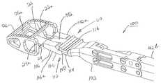
- FIG. 6is a top exploded perspective view of the monolithic cage of FIG. 3 and an inserter of the present invention prior to attachment of the inserter to the cage.
- FIG. 7is a side exploded elevation view of the exploded monolithic cage and inserter of FIG. 6 .
- FIG. 8is a top plan view of the monolithic cage and inserter of FIG. 6 with an expandable tip portion of the inserter inserted into the monolithic cage prior to expansion.
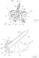
- FIG. 9Ais a side elevation view of the monolithic cage and inserter of FIG. 8 with the expandable tip portion of the inserter expanded and attached to the monolithic cage after expansion.
- FIG. 9Bis an enlarged view of the expandable tip portion of the inserter attached to the monolithic cage as shown in FIG. 9A .
- FIGS. 10 and 11are perspective top views showing the expandable tip portion of the inserter attached to the monolithic cage after expansion.
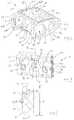
- FIG. 12is a top perspective view of the device of FIG. 1 with bone fixation screws extending therethrough.
- FIG. 13is a cross-sectional view of the device and bone fixation screws as seen along viewing lines XIII-XIII of FIG. 12 .
- a modular interbody fusion device 10 for insertion into the intradiscal space between opposing vertebraecomprising a monolithic cage 12 and an attachable modular plate 14 .
- device 10 as described hereinis suitable as a spinal fusion implant configured to contact endplates of opposing vertebral bodies in a spine defining a volume between vertebrae in the intradiscal space after a natural disc has been removed in preparation for the implantation of the device.
- modular interbody fusion device 10is configured and sized for particular application in the lumbar section of the spine with insertion from the anterior approach. Other applications and insertion directions, however, are also contemplated, as will be described.
- Cage 12is a monolithic body having a distal end 12 a and a proximal end 12 b , an upper bone contact structure 16 , a lower bone contact structure 18 and a pair of spaced apart side structures 20 joining upper bone contact structure 16 and lower bone contact structure 18 .
- Cage 12includes an outer top surface 16 a supported by the underlying upper bone contact structure 16 , and an outer bottom surface 18 a supported by the underlying lower bone contact structure 18 .
- Top surface 16 a and bottom surface 18 aare preferably contoured as curved, convex surfaces so as to match the anatomic convexity and size of the cartilaginous endplates of the respective mating vertebral body surfaces. This anatomical fit ensures proper bony engagement to provide biomechanical support of the bony surfaces to resist device subsidence during expansion.
- Upper bone contact structure 16 and lower bone contact structure 18include thereon a number of serrations 16 b and 18 b serving a bone anchoring function, the apices of serrations 16 b , 18 b respectively defining top surface 16 a and bottom surface 18 a of cage 12 . These functional anchors may assist in holding the device 10 in position during implantation or may hold the device 10 in position after implantation.
- top and bottom surfaces 16 a , 18 amay in certain situations be formed to have a contour other than convex, such as being linear.
- one surface, such as top surface 16 amay be curved while bottom surface 18 a may be linear.
- device 10is a modular anterior lumbar interbody fusion (ALIF) device wherein distal end 12 a is the posterior end and proximal end 12 b is the anterior end.
- monolithic cage 12is of fixed dimension, and the height of posterior distal end 12 a is less than the height of anterior proximal end 12 b , with upper and lower bone contact structures 16 , 18 inclining toward each other distally to thereby define a wedge-shaped lordotic configuration for anterior placement. It should be appreciated, however, that only one of upper bone contact structure 16 or lower bone contact structure 18 may be angled toward the other.
- each of upper and lower bone contact structures 16 , 18is angled approximately the same amount from the centerline of device 10 .
- upper bone contact structure 16is 7.5 degrees from the centerline and the lower bone contact structure 18 is 7.5 degrees front the centerline as well.
- the included angle between upper and lower bone contact structures 16 and 18is 15 degrees, in this example. It should be understood that in some instances monolithic cage 12 may be expandable and also sized and configured to conform to other interbody fusion procedures.
- Opposing spaced apart side structures 20 of cage 12are interconnected to each other adjacent proximal end 12 b by a laterally extending top cross member 22 and a laterally extending bottom cross member 24 .
- the distal-facing surfaces 22 a ( FIGS. 1B and 2B ) and 24 a ( FIG. 3 ) of top cross member 22 and bottom cross member 24provide respective instrument engagement surfaces for releasable connection with an insert or instrument, and will be described.
- Opposing spaced apart side structures 20 of cage 12are interconnected to each other adjacent distal end 12 a by a laterally extending closed posterior end wall 26 .
- the upper and lower bone contact structures 16 , 18 , side structures 20 and rear end wall 26define a hollow interior 28 of cage 12 .
- Upper and lower bone contact structures 16 , 18include upper and lower openings 30 and 32 respectively therethrough allowing bone graft or other osteogenic materials to flow into the hollow interior 28 of the cage 12 and to pass through and contact adjacent vertebral body endplates thereby aiding in the fusion of the device 10 thereto.
- the top cross member 22 , posterior end wall 26 and opposing side structures 20define upper opening 30 through top surface 16 a
- the bottom cross member 24 , posterior end wall 26 and side structures 20define lower opening 32 through bottom surface 18 a
- a proximal opening 34is defined between top and bottom cross members 22 , 24 and side structures 20 .
- Upper opening 30 , lower opening 32 and proximal opening 34all communicate with hollow interior 28 .
- Proximal end 12 b of cage 12is defined by a pair of spaced opposing arms 36 and 38 projecting proximally from side structures 20 , with arms 36 and 38 interconnecting upper and lower bone contact structures 16 , 18 .
- Arms 36 and 38 together with top and bottom cross members 22 , 24define a pocket 40 ( FIG. 2B ) for resilient receipt of modular plate 14 as will be described.
- Pocket 40communicates with proximal opening 34 .
- Each arm 36 , 38includes thereon a key 36 a , 38 a extending into pocket 40 and projecting laterally toward each other. Keys 36 a and 38 a are disposed approximately midway between upper and lower bone contact surfaces 16 , 18 at the proximal end 12 b .
- Arms 36 , 38each define a generally blunt trailing end while the distal end 12 a is defined by end wall 26 which similarly includes a generally blunt leading end.
- the generally blunt endsallow the upper and lower bone contact structures 16 , 18 to have a length along and generally parallel to axis 42 optimized for maximum contact with endplates of opposing vertebral bodies.
- Side structures 20each comprise a generally centrally located load bearing column 44 and a pair of windows 46 and 48 respectively extending therethrough and communicating with the hollow interior 28 . Communicating with respective windows 46 are latch engagement surfaces 36 b and 38 b on the distal surfaces of arms 36 and 38 for engagement with a resilient latch on modular plate 14 , as will be described
- Plate 14is generally rectangular in configuration having a height, H (as illustrated in FIG. 5 ), a width, W and a thickness, t, as shown in FIG. 2B .
- Height, H, width, W and thickness, tare all sized and configured such that modular plate 14 fits fully within pocket 40 of cage 12 , as will be described, without adding to the profile of cage 12 .
- Plate 14 in one arrangementhas three openings 50 extending therethrough for receipt and retention of fixation elements, such as bone screws, described hereinbelow. Each opening 50 is oriented with its axis 50 a ( FIG. 5 ) lying obliquely with respect the height, H of plate 14 .
- the axes 50 a of the two outside holes 50are generally parallel to each other, with each of these holes 50 being oriented to receive a respective fixation element for attachment to an endplate of an inferior vertebral body.
- the axis 50 a of middle hole 50 in the shown arrangementis transverse to the axes 50 a of the two outside holes, with middle hole 50 being oriented to receive a fixation element for attachment to an endplate of a superior vertebral body. It should be appreciated that a different number of holes with other axis orientations may also be contemplated.
- each hole 50Associated with each hole 50 is a screw retention clip 52 for retaining a fixation element in place without backing out after implantation.
- Clip 52comprises a cantilevered arm 52 a that is joined to plate 14 within hole 50 at one end and that terminates at its free end in a flange 52 b that extends transversely relative to axis 50 a .
- a fixation elementsuch as a bone screw
- the bone screw headwill temporarily displace clip arm 52 a until the head passes flange 52 b at which time arm 52 a will spring back with flange 52 b overlying the head of the bone screw, as will be described.
- modular plate 14 and clip 52are integrally formed as a unitary piece formed of the same material.
- clip 52may be formed separately out of the same or different material as plate 14 and attached to plate 14 by any suitable technique.
- latch 54Disposed on each of the side surfaces 14 a of plate 14 is a resilient latch 54 for resiliently attaching plate 14 to cage 12 .
- latch 54comprises a pair of cantilevered latch elements 54 a spaced by a keyway 56 therebetween. Each latch element is attached to a respective side surface 14 a of plate 14 at one end with its free end 54 b extending toward the anterior surface 14 b of plate 14 , as shown in FIG. 2B .
- resilient latch 54is configured and sized to lie fully within the confines of the thickness, t of modular plate 14 .
- resilient latch 54is also configured and sized to lie fully within the confines of the height, H of modular plate 14 .
- Each keyway 56is sized and dimensioned to respectively receive keys 36 a , 38 a in a manner to guide plate 14 into pocket 40 during attachment to cage 12 .
- keyways 56are disposed approximately midway between the top and bottom surfaces 14 c and 14 d of plate 14 . The midway disposition of the keys 36 a , 38 a and keyways 56 allow for a universal connection feature between a single modular plate 14 and different size cages 12 , as will be described.
- latch engagement surfaces 36 b and 38 bin the described arrangement as being disposed on distal surfaces of arms 36 and 38 , it should be appreciated that in other arrangements latch engagement surfaces may be provided on the distal surfaces of cross members 22 and 24 .
- a resilient latch is 54may be provided on top surfaces 14 c , 14 d respectively for complementary engagement with such latch engagement surfaces, with such latches being disposed within the confines of plate thickness, t.
- Suitable biocompatible metallic materials for cage 12 and modular plate 14include pure titanium, tantalum, cobalt-chromium alloys, titanium alloys (e.g., nickel titanium alloys and tungsten titanium alloys), and stainless steel alloys.
- Suitable polymeric materials for cage 12 and modular plate 14include members of the polyaryletherketone (PAEK) family, e.g., polyetheretherketone (PEEK), carbon-reinforced PEEK, polyetherketoneketone (PEKK); polysulfone; polyetherimide; polyimide; ultra-high molecular weight polyethylene (UHMWPE); or cross-linked UHMWPE.
- Ceramic materialssuch as aluminum oxide or alumina, zirconium oxide or zirconia, compact of particulate diamond, or pyrolytic carbon may be included in such polymers.
- Inserter 100comprises an elongate cage holder 102 having a distal end 102 a and a proximal end 102 b .
- Proximal end 102 bis of size and configuration for grasping by a surgeon and of extent to extend outwardly of the surgical site of a patient.
- Distal end 102 aterminates in an expandable tip portion 104 specifically configured for receipt through proximal opening 34 and into interior 28 of cage 12 .
- Expandable tip portion 104includes a pair of plates, namely lower plate 106 and upper plate 108 that are movably separable in a direction transverse to the elongate direction of holder 102 by a linkage mechanism 110 , as illustrated in FIG. 9A .
- Mechanism 110may be actuated manually by a pliers type handle at the proximal end 102 b (not shown) or any other suitable actuation technique.
- Inserter 100is formed of stainless steel although other suitable materials may be used.
- each of the movable plates 106 and 108is provided with a connection surface 110 and 112 , respectively, that is defined by a plurality of laterally extending, axially spaced grooves 114 and 116 .
- Each groove 114 , 116is spaced from the distal end 104 a of the expandable distal top portion 104 by a different dimension, e.g., d 1 and d 2 , as shown in FIG. 7 .
- Each groove 114 , 116has an inclined surface 114 a , 116 a adjacent thereto, such inclined surfaces 114 a , 116 a being oriented to face in the proximal direction.
- the distal end 104 aUpon insertion of the expandable distal tip portion 104 into the interior 28 of cage 12 , the distal end 104 a is configured to engage an interior surface 26 a of posterior end wall 26 .
- one of the grooves 114 on lower plate 106is configured to engage engagement surface 24 a on bottom cross member 24 while one of the grooves 116 upper plate member 108 is configured to engage engagement surface 22 a of top cross member 22 .
- the function of the formation of the multiple grooves 114 , 116 on cage holder 102is to allow the use of a single inserter 100 with a plurality of different cages 12 , each having at least different lengths.
- the dimension d 1 , d 2 , etc. between the distal end 104 a of holder 102 and each groove 114 , 116is formed to substantially match the respective different distance that each cage 12 is spaced between the posterior interior surface 26 a of posterior end wall 26 and the instrument engagement surfaces 22 a and 24 a .
- three differently size cages 12may be provided in a kit of parts to be selected by the surgeon in accordance with surgical and anatomical conditions. It should be appreciated, however, that more or less than three grooves 114 , 116 may be provided with a commensurate number of differently sized cages 12 .
- lower plate 106 and upper plate 108are each configured to have an exterior surface that is formed to substantially match the outer contour of the top surface 16 a and bottom surface 18 a of cage 12 . Where top surface 16 a and bottom surface 18 a are convex as described hereinabove, the exterior surfaces are formed to substantially match the radius of curvature of such convexities.
- upper plate 108includes a central convex exterior surface 108 a while lower plate 106 has a pair of convex exterior surfaces 106 a on each lateral side of upper exterior surface 108 a , as shown in FIG. 9A .
- upper exterior surface 108 aextends into upper opening 30 of cage 12 while lower exterior surfaces 106 a extends into lower opening 32 of cage 12 .
- exterior surfaces 106 a , 108 alie no less than flush with respect to top surface 16 a and bottom surface 18 a along substantially the full axial length of exterior surfaces 106 a , 108 a , as shown in FIG. 9B . Accordingly, surface 106 a may lie slightly exteriorly below bottom surface 18 a , while exterior surface 108 a may lie slightly exteriorly above top surface 16 a.
- kits of parts including a plurality of cages 12 discussed abovemay be provided where the cages 12 are formed to include a variety of different lengths and differing widths or heights, or are selected to include differing lordotic angles between the distal and proximal ends 12 a , 12 b .
- Each of these kitsmay include a single inserter 100 for attachment to a selected cage 12 and introduction of the selected cage 12 into a chosen site in the intradiscal space between opposing vertebral bodies.
- the kit of partsmay include a single modular plate 14 that is configured to be received within the pocket 40 of any of the plurality of cages for attachment to such cage.
- the pocket 40 of each of cages 12is configured to be of approximately the same size and shape such that a modular plate 14 may be received therein for attachment to the selected cages 12 , as will be described.
- Attachmentis effected by introducing expandable tip portion 104 through proximal opening 34 of the selected cage 12 and into hollow interior 28 until distal end 104 a of holder 102 contacts interior surface 26 a of posterior end wall 26 .
- Expandable tip potion 104is expanded by movably separating lower plate 106 and upper plate 108 away from each other by suitable actuation of inserter linkage mechanism 110 .
- cross members 22 and 24will engage one of the grooves 114 , 116 as described above until tight connection between selected cage 12 and holder is achieved.
- Proper attachment of cage 12 with inserter 100is shown in FIGS. 10 and 11 , with cage 12 in position for insertion.
- Cage 10is then inserted into the disc space by inserter 100 through manipulation by the surgeon.
- lower exterior surface 106 a and upper exterior surface 108 alying no less than flush with the contours of the respective bottom surface 18 a and 16 a as depicted in FIG. 9B , the surfaces of the endplates of opposing vertebral bodies adjacent the intradiscal space are protected from undue abrasion during insertion of cage 10 .
- inserter 100is removed by suitably contracting expandable tip portion 104 by moving lower plate 106 and upper plate 108 toward each other and withdrawing cage holder 102 from inserted cage 12 .
- the open architecture of cage 12allows for proper preparation of the opposing vertebral body endplates whereby disc preparation tools may be introduced through proximal opening 34 of cage 12 and then through upper opening 30 and lower opening 32 for direct access to the vertebral body endplates.
- the generally blunt proximal and distal ends of cage arms 36 , 38 and of cage distal end 12 aallow for optimization of implant length for maximum contact area between cage 12 and the opposing vertebral body endplates.
- the compression on cage 12 provided by the ligaments surrounding vertebral bodies on the serrations 16 b and 18 bwill serve to anchor the cage 12 in position.
- all or a portion of the interior 28 of cage 12 as well as the disc space surrounding cage 12may be filled in situ with a suitable bone graft material containing bone growth promoting substances.
- a suitable bone graft materialcontaining bone growth promoting substances.
- Osteogenic materials or therapeutic compositionsmay also be used, such materials and compositions being more fully described in commonly owned U.S. Pat. No. 8,641,769, entitled “A Plastically Deformable Inter-Osseous Device”, issued to Hugues Malandain on Feb. 4, 2014, and incorporated in its entirety by reference herein.
- modular plate 14is resiliently attached in situ to the inserted cage 12 in a manner as described hereinabove with keys 36 a , 38 a on cage 12 guiding the attachment by complementary receipt into keyways 56 of modular plate 14 .
- Resilient latching of latches 54 with latch engagement surfaces 36 b and 38 b on the distal surfaces of arms 36 and 38completes the assembly of modular anterior lumbar interbody fusion device 10 .
- modular plate 14provides two functions. First, modular plate 14 serves as a barrier restricting backflow of bone graft material out from cage 12 , thus contributing to the maintenance of compressive load between the graft material and the endplates of the opposing vertebral bodies.
- modular plate 14serves as a structure for the introduction of suitable fixation elements to stabilize the position of interbody fusion device 10 in the disc space.
- fixation elementsuch as bone screws 300 may be introduced through plate openings 50 as described hereinabove.
- Each bone screw 300includes a threaded elongate shaft 302 and an enlarged head 304 containing a suitable socket 306 for suitable attachment to a suitable driver.
- each bone screw 300passes through an opening 50 with threaded shafts entering respective vertebral body endplates, the head 304 of each bone screw 300 will temporarily displace clip arm 52 a until the head 304 passes flange 52 b , at which time arm 52 a will spring back with flange 52 b overlying the head 304 of bone screw 300 .
- the disposition of flange 52 b in overlying relation relative to head 304will serve to restrict backout of bone screw 300 from interbody fusion device 10 .
- the modular anterior interbody fusion device 10 as described hereinincludes particular features that may be desirable to a surgeon.
- the module cage 12provides an accessible proximal opening that allows for clear visualization into the disc space after insertion while also providing a structure to prevent load induced subsidence by virtue of the anterior top and bottom cross members 22 , 24 that span the width of cage 12 .
- Such cross members 22 , 24also provide surfaces for engaging cage 12 during insertion/removal process.
- modular plate 14provides a structure to close the proximal portion of monolithic cage 12 after introduction of bone graft material while allowing for use with integrated fixation.
- the attachment features between the modular cage 12 and modular plate 14are universal throughout various configurations, flexibility for surgical use with minimal components is enhanced.
- modular interbody fusion device 10may also be sized and configured for use in other sections of the spine, such as the cervical and thoracic spine, and may also be inserted in a posterior, posterolateral, anterior lateral or lateral approach.
- cage 12has been described in one arrangement as being monolithic, it should be understood that a cage formed of more than one part may also be use, particularly when used with the inserter 100 described herein. Accordingly, it should be appreciated that only the preferred embodiments have been presented and that all changes, modifications and further applications that come within the spirit of the invention are desired to be protected.
Landscapes
- Health & Medical Sciences (AREA)
- Biomedical Technology (AREA)
- Engineering & Computer Science (AREA)
- Orthopedic Medicine & Surgery (AREA)
- Neurology (AREA)
- Transplantation (AREA)
- Vascular Medicine (AREA)
- Heart & Thoracic Surgery (AREA)
- Oral & Maxillofacial Surgery (AREA)
- Life Sciences & Earth Sciences (AREA)
- Animal Behavior & Ethology (AREA)
- General Health & Medical Sciences (AREA)
- Public Health (AREA)
- Veterinary Medicine (AREA)
- Cardiology (AREA)
- Physical Education & Sports Medicine (AREA)
- Prostheses (AREA)
Abstract
Description
Claims (19)
Priority Applications (1)
| Application Number | Priority Date | Filing Date | Title |
|---|---|---|---|
| US15/293,391US10500063B2 (en) | 2016-10-14 | 2016-10-14 | Modular interbody fusion device |
Applications Claiming Priority (1)
| Application Number | Priority Date | Filing Date | Title |
|---|---|---|---|
| US15/293,391US10500063B2 (en) | 2016-10-14 | 2016-10-14 | Modular interbody fusion device |
Publications (2)
| Publication Number | Publication Date |
|---|---|
| US20180104067A1 US20180104067A1 (en) | 2018-04-19 |
| US10500063B2true US10500063B2 (en) | 2019-12-10 |
Family
ID=61902115
Family Applications (1)
| Application Number | Title | Priority Date | Filing Date |
|---|---|---|---|
| US15/293,391Expired - Fee RelatedUS10500063B2 (en) | 2016-10-14 | 2016-10-14 | Modular interbody fusion device |
Country Status (1)
| Country | Link |
|---|---|
| US (1) | US10500063B2 (en) |
Cited By (1)
| Publication number | Priority date | Publication date | Assignee | Title |
|---|---|---|---|---|
| US20220015926A1 (en)* | 2010-04-21 | 2022-01-20 | Globus Medical, Inc. | Implant packaging cartridge and insertion tool |
Families Citing this family (3)
| Publication number | Priority date | Publication date | Assignee | Title |
|---|---|---|---|---|
| EP2967900B1 (en) | 2013-03-15 | 2023-10-04 | Revivo Medical, LLC | Intervertebral cage |
| US11103360B2 (en) | 2019-03-19 | 2021-08-31 | Robert Woodruff | Spinal fusion cage and method of operation |
| CN113786270A (en)* | 2021-09-03 | 2021-12-14 | 北京爱康宜诚医疗器材有限公司 | Intervertebral fusion prosthesis and processing method of intervertebral fusion prosthesis |
Citations (49)
| Publication number | Priority date | Publication date | Assignee | Title |
|---|---|---|---|---|
| US3574381A (en) | 1968-11-15 | 1971-04-13 | Robert M Ocheltree | Clamping tool |
| US5397364A (en) | 1993-10-12 | 1995-03-14 | Danek Medical, Inc. | Anterior interbody fusion device |
| US5782830A (en) | 1995-10-16 | 1998-07-21 | Sdgi Holdings, Inc. | Implant insertion device |
| US6235059B1 (en) | 1996-04-03 | 2001-05-22 | Scient'x (Societe A Responsabilite Limitee) | Intersomatic setting and fusion system |
| US6447546B1 (en) | 2000-08-11 | 2002-09-10 | Dale G. Bramlet | Apparatus and method for fusing opposing spinal vertebrae |
| US6468311B2 (en) | 2001-01-22 | 2002-10-22 | Sdgi Holdings, Inc. | Modular interbody fusion implant |
| FR2827156A1 (en) | 2001-07-13 | 2003-01-17 | Ldr Medical | Surgical spinal cage for fusing vertebrae has cage formed as ring with fixing bar having cross bore and formed vertebra engagement surfaces |
| US6558388B1 (en) | 1999-08-30 | 2003-05-06 | Sulzer Orthopedics Ltd. | Intramedullary nail for the humerus |
| US20030233145A1 (en)* | 2002-03-11 | 2003-12-18 | Landry Michael E. | Instrumentation and procedure for implanting spinal implant devices |
| US20060129238A1 (en)* | 2004-10-26 | 2006-06-15 | Adam Paltzer | Spinal stabilization device and methods |
| US7232464B2 (en) | 2002-02-19 | 2007-06-19 | Synthes (Usa) | Intervertebral implant |
| US7235082B2 (en) | 2003-08-12 | 2007-06-26 | Depuy Spine, Inc. | Device for insertion of implants |
| US20070250167A1 (en) | 2003-04-21 | 2007-10-25 | Rsb Spine Llc | Spine implants |
| US20080140207A1 (en)* | 2006-12-07 | 2008-06-12 | Interventional Spine, Inc. | Intervertebral implant |
| US20080208342A1 (en)* | 2007-02-27 | 2008-08-28 | Zimmer Spine, Inc. | Spinal implant |
| US20080249569A1 (en) | 2007-04-03 | 2008-10-09 | Warsaw Orthopedic, Inc. | Implant Face Plates |
| US20080281425A1 (en) | 2007-02-21 | 2008-11-13 | John Thalgott | Orthopaedic Implants and Prostheses |
| US7674297B2 (en) | 2002-06-14 | 2010-03-09 | U.S. Spinal Technologies, Llc | Anatomic vertebral cage |
| US20100145459A1 (en) | 2008-11-07 | 2010-06-10 | Mcdonough William P | Zero-profile interbody spacer and coupled plate assembly |
| US20100298941A1 (en)* | 2009-05-19 | 2010-11-25 | Robert Hes | Dynamic trial implants |
| US7846207B2 (en) | 2003-02-06 | 2010-12-07 | Synthes Usa, Llc | Intervertebral implant |
| US8062303B2 (en) | 2006-08-16 | 2011-11-22 | K2M, Inc. | Apparatus and methods for inserting an implant |
| US20120197317A1 (en)* | 2011-02-01 | 2012-08-02 | Alejandro Lezama | Quick release spinal implant insertion device |
| US20120197401A1 (en) | 2011-01-27 | 2012-08-02 | Warsaw Orthopedic, Inc. | Interbody spinal implants with modular add-on devices |
| US8268000B2 (en) | 2007-04-03 | 2012-09-18 | Warsaw Orthopedic, Inc. | Composite interbody spacer |
| US8273127B2 (en) | 2007-06-06 | 2012-09-25 | Spinesmith Partners, L.P. | Interbody fusion device and associated methods |
| US20120253406A1 (en) | 2009-11-03 | 2012-10-04 | Howmedica Osteonics Corp. | Intervertebral implant with integrated fixation |
| US8282682B2 (en) | 2003-09-30 | 2012-10-09 | X-Spine Systems, Inc. | Fusion system and method for fusing spinal bones |
| US20120277872A1 (en) | 2007-06-06 | 2012-11-01 | Richard Kana | Interbody fusion device with snap on anterior plate and associated methods |
| US20120277873A1 (en) | 2007-06-06 | 2012-11-01 | Richard Kana | Interbody fusion device with lipped anterior plate and associated methods |
| US8328872B2 (en) | 2008-09-02 | 2012-12-11 | Globus Medical, Inc. | Intervertebral fusion implant |
| US8454700B2 (en) | 2011-10-04 | 2013-06-04 | Zimmer Spine, Inc. | Interbody vertebral spacer |
| US8460388B2 (en) | 2011-10-28 | 2013-06-11 | Incite Innovation Llc | Spinal interbody device |
| US8709083B2 (en) | 2009-06-04 | 2014-04-29 | William E. Duffield | Intervertebral fusion implant |
| US8728165B2 (en) | 2007-11-12 | 2014-05-20 | Centinel Spine, Inc. | Orthopaedic implants and protheses |
| US20140277745A1 (en) | 2013-03-15 | 2014-09-18 | Ecolab Usa Inc. | Monitoring hydraulic fracturing |
| US20140277477A1 (en)* | 2013-03-12 | 2014-09-18 | Spine Wave, Inc. | Apparatus and Methods for Inserting an Interbody Fusion Device |
| US20150100125A1 (en)* | 2013-10-07 | 2015-04-09 | Spine Wave, Inc. | Expandable anterior lumbar interbody fusion device |
| US20150202051A1 (en) | 2014-01-17 | 2015-07-23 | Kolum, Inc. | Spinal fusion system |
| US9155631B2 (en) | 2010-04-08 | 2015-10-13 | Globus Medical Inc. | Intervertbral implant |
| US9161841B2 (en) | 2011-07-12 | 2015-10-20 | Spinesmith Partners, L.P. | Interbody fusion device and associated methods |
| US20150305883A1 (en) | 2009-11-09 | 2015-10-29 | Centinel Spine, Inc. | Spinal implant with attachment system |
| US20160015523A1 (en) | 2014-07-16 | 2016-01-21 | Amedica Corporation | Intervertebral spacers and related methods and instruments |
| US9241809B2 (en) | 2010-12-21 | 2016-01-26 | DePuy Synthes Products, Inc. | Intervertebral implants, systems, and methods of use |
| US20160151166A1 (en) | 2014-07-01 | 2016-06-02 | Alliance Partners, Llc | Low profile standalone cervical interbody with screw locking clips and method of using same |
| US9480577B2 (en) | 2013-01-17 | 2016-11-01 | Stryker European Holdings I, Llc | Retaining mechanism, implant, and tool |
| US20160324657A1 (en) | 2011-11-17 | 2016-11-10 | Zimmer Biomet Spine, Inc. | Modular anchor bone fusion cage |
| US20160338849A1 (en)* | 2015-05-21 | 2016-11-24 | Globus Medical, Inc. | Device and method for deployment of an anchoring device for intervertebral spinal fusion |
| US20160374831A1 (en)* | 2015-06-25 | 2016-12-29 | Institute for Musculoskeletal Science and Education, Ltd. | Interbody fusion device and system for implantation |
- 2016
- 2016-10-14USUS15/293,391patent/US10500063B2/ennot_activeExpired - Fee Related
Patent Citations (56)
| Publication number | Priority date | Publication date | Assignee | Title |
|---|---|---|---|---|
| US3574381A (en) | 1968-11-15 | 1971-04-13 | Robert M Ocheltree | Clamping tool |
| US5397364A (en) | 1993-10-12 | 1995-03-14 | Danek Medical, Inc. | Anterior interbody fusion device |
| US5782830A (en) | 1995-10-16 | 1998-07-21 | Sdgi Holdings, Inc. | Implant insertion device |
| US6235059B1 (en) | 1996-04-03 | 2001-05-22 | Scient'x (Societe A Responsabilite Limitee) | Intersomatic setting and fusion system |
| US6558388B1 (en) | 1999-08-30 | 2003-05-06 | Sulzer Orthopedics Ltd. | Intramedullary nail for the humerus |
| US6447546B1 (en) | 2000-08-11 | 2002-09-10 | Dale G. Bramlet | Apparatus and method for fusing opposing spinal vertebrae |
| US6468311B2 (en) | 2001-01-22 | 2002-10-22 | Sdgi Holdings, Inc. | Modular interbody fusion implant |
| FR2827156A1 (en) | 2001-07-13 | 2003-01-17 | Ldr Medical | Surgical spinal cage for fusing vertebrae has cage formed as ring with fixing bar having cross bore and formed vertebra engagement surfaces |
| US7594931B2 (en) | 2001-07-13 | 2009-09-29 | Ldr Medical | Vertebral cage device with modular fixation |
| US8147556B2 (en) | 2001-07-13 | 2012-04-03 | Ldr Medical | Vertebral cage device with modular fixation |
| US9078765B2 (en) | 2001-07-13 | 2015-07-14 | Ldr Medical | Vertebral cage device with modular fixation |
| US7232464B2 (en) | 2002-02-19 | 2007-06-19 | Synthes (Usa) | Intervertebral implant |
| US20030233145A1 (en)* | 2002-03-11 | 2003-12-18 | Landry Michael E. | Instrumentation and procedure for implanting spinal implant devices |
| US7674297B2 (en) | 2002-06-14 | 2010-03-09 | U.S. Spinal Technologies, Llc | Anatomic vertebral cage |
| US7846207B2 (en) | 2003-02-06 | 2010-12-07 | Synthes Usa, Llc | Intervertebral implant |
| US20070250167A1 (en) | 2003-04-21 | 2007-10-25 | Rsb Spine Llc | Spine implants |
| US7235082B2 (en) | 2003-08-12 | 2007-06-26 | Depuy Spine, Inc. | Device for insertion of implants |
| US8282682B2 (en) | 2003-09-30 | 2012-10-09 | X-Spine Systems, Inc. | Fusion system and method for fusing spinal bones |
| US20060129238A1 (en)* | 2004-10-26 | 2006-06-15 | Adam Paltzer | Spinal stabilization device and methods |
| US8062303B2 (en) | 2006-08-16 | 2011-11-22 | K2M, Inc. | Apparatus and methods for inserting an implant |
| US20080140207A1 (en)* | 2006-12-07 | 2008-06-12 | Interventional Spine, Inc. | Intervertebral implant |
| US20080281425A1 (en) | 2007-02-21 | 2008-11-13 | John Thalgott | Orthopaedic Implants and Prostheses |
| US20080208342A1 (en)* | 2007-02-27 | 2008-08-28 | Zimmer Spine, Inc. | Spinal implant |
| US20080249569A1 (en) | 2007-04-03 | 2008-10-09 | Warsaw Orthopedic, Inc. | Implant Face Plates |
| US8268000B2 (en) | 2007-04-03 | 2012-09-18 | Warsaw Orthopedic, Inc. | Composite interbody spacer |
| US8273127B2 (en) | 2007-06-06 | 2012-09-25 | Spinesmith Partners, L.P. | Interbody fusion device and associated methods |
| US20120277873A1 (en) | 2007-06-06 | 2012-11-01 | Richard Kana | Interbody fusion device with lipped anterior plate and associated methods |
| US20120277872A1 (en) | 2007-06-06 | 2012-11-01 | Richard Kana | Interbody fusion device with snap on anterior plate and associated methods |
| US8728165B2 (en) | 2007-11-12 | 2014-05-20 | Centinel Spine, Inc. | Orthopaedic implants and protheses |
| US8328872B2 (en) | 2008-09-02 | 2012-12-11 | Globus Medical, Inc. | Intervertebral fusion implant |
| US20100145459A1 (en) | 2008-11-07 | 2010-06-10 | Mcdonough William P | Zero-profile interbody spacer and coupled plate assembly |
| US20100298941A1 (en)* | 2009-05-19 | 2010-11-25 | Robert Hes | Dynamic trial implants |
| US8709083B2 (en) | 2009-06-04 | 2014-04-29 | William E. Duffield | Intervertebral fusion implant |
| US9033993B2 (en) | 2009-11-03 | 2015-05-19 | Howmedica Osteonics Corp. | Intervertebral implant with integrated fixation |
| US20120253406A1 (en) | 2009-11-03 | 2012-10-04 | Howmedica Osteonics Corp. | Intervertebral implant with integrated fixation |
| US20150305883A1 (en) | 2009-11-09 | 2015-10-29 | Centinel Spine, Inc. | Spinal implant with attachment system |
| US9155631B2 (en) | 2010-04-08 | 2015-10-13 | Globus Medical Inc. | Intervertbral implant |
| US9241809B2 (en) | 2010-12-21 | 2016-01-26 | DePuy Synthes Products, Inc. | Intervertebral implants, systems, and methods of use |
| US20120197401A1 (en) | 2011-01-27 | 2012-08-02 | Warsaw Orthopedic, Inc. | Interbody spinal implants with modular add-on devices |
| US20120197317A1 (en)* | 2011-02-01 | 2012-08-02 | Alejandro Lezama | Quick release spinal implant insertion device |
| US9161841B2 (en) | 2011-07-12 | 2015-10-20 | Spinesmith Partners, L.P. | Interbody fusion device and associated methods |
| US8454700B2 (en) | 2011-10-04 | 2013-06-04 | Zimmer Spine, Inc. | Interbody vertebral spacer |
| US8460388B2 (en) | 2011-10-28 | 2013-06-11 | Incite Innovation Llc | Spinal interbody device |
| US20160324657A1 (en) | 2011-11-17 | 2016-11-10 | Zimmer Biomet Spine, Inc. | Modular anchor bone fusion cage |
| US9480577B2 (en) | 2013-01-17 | 2016-11-01 | Stryker European Holdings I, Llc | Retaining mechanism, implant, and tool |
| US9358134B2 (en) | 2013-03-12 | 2016-06-07 | Spine Wave, Inc. | Method of inserting an interbody fusion device |
| US20140277477A1 (en)* | 2013-03-12 | 2014-09-18 | Spine Wave, Inc. | Apparatus and Methods for Inserting an Interbody Fusion Device |
| US8864830B2 (en) | 2013-03-12 | 2014-10-21 | Spine Wave, Inc. | Apparatus and methods for inserting an interbody fusion device |
| US20140277745A1 (en) | 2013-03-15 | 2014-09-18 | Ecolab Usa Inc. | Monitoring hydraulic fracturing |
| US20150100125A1 (en)* | 2013-10-07 | 2015-04-09 | Spine Wave, Inc. | Expandable anterior lumbar interbody fusion device |
| US9101489B2 (en) | 2013-10-07 | 2015-08-11 | Spine Wave, Inc. | Expandable anterior lumbar interbody fusion device |
| US20150202051A1 (en) | 2014-01-17 | 2015-07-23 | Kolum, Inc. | Spinal fusion system |
| US20160151166A1 (en) | 2014-07-01 | 2016-06-02 | Alliance Partners, Llc | Low profile standalone cervical interbody with screw locking clips and method of using same |
| US20160015523A1 (en) | 2014-07-16 | 2016-01-21 | Amedica Corporation | Intervertebral spacers and related methods and instruments |
| US20160338849A1 (en)* | 2015-05-21 | 2016-11-24 | Globus Medical, Inc. | Device and method for deployment of an anchoring device for intervertebral spinal fusion |
| US20160374831A1 (en)* | 2015-06-25 | 2016-12-29 | Institute for Musculoskeletal Science and Education, Ltd. | Interbody fusion device and system for implantation |
Cited By (2)
| Publication number | Priority date | Publication date | Assignee | Title |
|---|---|---|---|---|
| US20220015926A1 (en)* | 2010-04-21 | 2022-01-20 | Globus Medical, Inc. | Implant packaging cartridge and insertion tool |
| US12226322B2 (en)* | 2010-04-21 | 2025-02-18 | Globus Medical, Inc. | Implant packaging cartridge and insertion tool |
Also Published As
| Publication number | Publication date |
|---|---|
| US20180104067A1 (en) | 2018-04-19 |
Similar Documents
| Publication | Publication Date | Title |
|---|---|---|
| US9949842B2 (en) | Expandable anterior lumbar interbody fusion device | |
| US10016286B2 (en) | Method of inserting an interbody fusion device | |
| US9925064B2 (en) | Intervertebral fusion implant | |
| US9364343B2 (en) | Intervertebral fusion implant | |
| US8932358B1 (en) | Anterior intervertebral spacer and integrated plate assembly and methods of use | |
| US8828084B2 (en) | Dynamic interbody cage anchor system | |
| EP2047825B1 (en) | Minimally invasive lateral intervertebral fixation system | |
| US7780732B2 (en) | Spinal fusion cage and method of use | |
| US8163026B2 (en) | Interbody implant | |
| US20120095559A1 (en) | Intervertebral spinal implant, installation device and system | |
| CA2502784A1 (en) | Systems and techniques for restoring and maintaining intervertebral anatomy | |
| US10500063B2 (en) | Modular interbody fusion device | |
| HK1089076B (en) | Intervertebral implant for spinal column, kit having the same and method for inserting the same |
Legal Events
| Date | Code | Title | Description |
|---|---|---|---|
| AS | Assignment | Owner name:SPINE WAVE, INC., CONNECTICUT Free format text:ASSIGNMENT OF ASSIGNORS INTEREST;ASSIGNORS:SKOLNICK, EDWARD CHARLES;CARSON, CHRISTOPHER P.;REEL/FRAME:040490/0935 Effective date:20161014 | |
| STPP | Information on status: patent application and granting procedure in general | Free format text:RESPONSE TO NON-FINAL OFFICE ACTION ENTERED AND FORWARDED TO EXAMINER | |
| STPP | Information on status: patent application and granting procedure in general | Free format text:FINAL REJECTION MAILED | |
| STPP | Information on status: patent application and granting procedure in general | Free format text:RESPONSE AFTER FINAL ACTION FORWARDED TO EXAMINER | |
| STPP | Information on status: patent application and granting procedure in general | Free format text:NOTICE OF ALLOWANCE MAILED -- APPLICATION RECEIVED IN OFFICE OF PUBLICATIONS | |
| STCF | Information on status: patent grant | Free format text:PATENTED CASE | |
| AS | Assignment | Owner name:SILICON VALLEY BANK, MASSACHUSETTS Free format text:SECURITY INTEREST;ASSIGNOR:SPINE WAVE, INC.;REEL/FRAME:062886/0507 Effective date:20230228 | |
| FEPP | Fee payment procedure | Free format text:MAINTENANCE FEE REMINDER MAILED (ORIGINAL EVENT CODE: REM.); ENTITY STATUS OF PATENT OWNER: SMALL ENTITY | |
| LAPS | Lapse for failure to pay maintenance fees | Free format text:PATENT EXPIRED FOR FAILURE TO PAY MAINTENANCE FEES (ORIGINAL EVENT CODE: EXP.); ENTITY STATUS OF PATENT OWNER: SMALL ENTITY | |
| STCH | Information on status: patent discontinuation | Free format text:PATENT EXPIRED DUE TO NONPAYMENT OF MAINTENANCE FEES UNDER 37 CFR 1.362 | |
| FP | Lapsed due to failure to pay maintenance fee | Effective date:20231210 |