US10499968B2 - Cable plugs for bone plates - Google Patents
Cable plugs for bone platesDownload PDFInfo
- Publication number
- US10499968B2 US10499968B2US14/657,188US201514657188AUS10499968B2US 10499968 B2US10499968 B2US 10499968B2US 201514657188 AUS201514657188 AUS 201514657188AUS 10499968 B2US10499968 B2US 10499968B2
- Authority
- US
- United States
- Prior art keywords
- cable
- cable plug
- plug
- bone plate
- aperture
- Prior art date
- Legal status (The legal status is an assumption and is not a legal conclusion. Google has not performed a legal analysis and makes no representation as to the accuracy of the status listed.)
- Active, expires
Links
- KVLCIHRZDOKRLK-UHFFFAOYSA-NC(C1)C2CCCCC1C2Chemical compoundC(C1)C2CCCCC1C2KVLCIHRZDOKRLK-UHFFFAOYSA-N0.000description1
Images


Classifications
- A—HUMAN NECESSITIES
- A61—MEDICAL OR VETERINARY SCIENCE; HYGIENE
- A61B—DIAGNOSIS; SURGERY; IDENTIFICATION
- A61B17/00—Surgical instruments, devices or methods
- A61B17/56—Surgical instruments or methods for treatment of bones or joints; Devices specially adapted therefor
- A61B17/58—Surgical instruments or methods for treatment of bones or joints; Devices specially adapted therefor for osteosynthesis, e.g. bone plates, screws or setting implements
- A61B17/68—Internal fixation devices, including fasteners and spinal fixators, even if a part thereof projects from the skin
- A61B17/82—Internal fixation devices, including fasteners and spinal fixators, even if a part thereof projects from the skin for bone cerclage
- A—HUMAN NECESSITIES
- A61—MEDICAL OR VETERINARY SCIENCE; HYGIENE
- A61B—DIAGNOSIS; SURGERY; IDENTIFICATION
- A61B17/00—Surgical instruments, devices or methods
- A61B17/56—Surgical instruments or methods for treatment of bones or joints; Devices specially adapted therefor
- A61B17/58—Surgical instruments or methods for treatment of bones or joints; Devices specially adapted therefor for osteosynthesis, e.g. bone plates, screws or setting implements
- A61B17/68—Internal fixation devices, including fasteners and spinal fixators, even if a part thereof projects from the skin
- A61B17/84—Fasteners therefor or fasteners being internal fixation devices
- A61B17/842—Flexible wires, bands or straps
- A—HUMAN NECESSITIES
- A61—MEDICAL OR VETERINARY SCIENCE; HYGIENE
- A61B—DIAGNOSIS; SURGERY; IDENTIFICATION
- A61B17/00—Surgical instruments, devices or methods
- A61B17/56—Surgical instruments or methods for treatment of bones or joints; Devices specially adapted therefor
- A61B17/58—Surgical instruments or methods for treatment of bones or joints; Devices specially adapted therefor for osteosynthesis, e.g. bone plates, screws or setting implements
- A61B17/88—Osteosynthesis instruments; Methods or means for implanting or extracting internal or external fixation devices
- A61B17/8861—Apparatus for manipulating flexible wires or straps
- A—HUMAN NECESSITIES
- A61—MEDICAL OR VETERINARY SCIENCE; HYGIENE
- A61B—DIAGNOSIS; SURGERY; IDENTIFICATION
- A61B17/00—Surgical instruments, devices or methods
- A61B17/56—Surgical instruments or methods for treatment of bones or joints; Devices specially adapted therefor
- A61B17/58—Surgical instruments or methods for treatment of bones or joints; Devices specially adapted therefor for osteosynthesis, e.g. bone plates, screws or setting implements
- A61B17/68—Internal fixation devices, including fasteners and spinal fixators, even if a part thereof projects from the skin
- A61B17/80—Cortical plates, i.e. bone plates; Instruments for holding or positioning cortical plates, or for compressing bones attached to cortical plates
Definitions
- the present inventionrelates to systems for coupling surgical cables to bone plates when reducing bone fractures or repairing fractured bones. More particularly, the invention relates to systems that utilize a cable plug or a cable attachment plate, affixed to a bone plate, to receive and retain a surgical cable.
- the surgical cablemay be oriented with respect to the bone at a plurality of angles relative to the longitudinal axis of the bone.
- Surgical cablesare used in many surgical procedures. They are generally used to encircle the bone alone, or the bone and a bone plate, to facilitate fixation of one or more bone fragments. Some bone fixation systems that use surgical cable also use a bone plate having a length sufficient to span the bone fragments, fixation screws to couple the bone plate to the bone, adapters to couple the cable to the bone plate, and crimp devices for securing ends of the cable. In these systems, the surgical cable is generally coupled to the bone or the bone plate at 90° from the longitudinal axis of the bone.
- the cablemay tend to move from its coupled position with respect to the bone plate.
- a longitudinal axis of the cablewill generally tend to be angled at less than 90° from the longitudinal axis of the bone. This may result in shear stresses and strains in the surgical cable that cause the bone plate to shift relative to the bone.
- fixation screwsfunction to both couple the bone plate to bone and serve as a means for coupling the cable at a certain position along a length of the bone plate. If the fixation screws are used to couple the cable to the bone plate, then the cable is generally received in a slot or bore in a head portion of the fixation screws. Such fixation screws also act as an adapter. The head portion of the fixation screws are generally integrally coupled to a shaft of the fixation screws but may be a separate component that is coupled to the shaft of the fixation screws.
- the adapters and fixation screws explained abovegenerally function to prevent migration of surgical cable along a longitudinal axis of a bone plate. These systems do not, however, provide a means of orienting the surgical cable at an angle less than 90° from the longitudinal axis of the bone. Therefore, they cannot sufficiently eliminate the stresses and strains in the surgical cable which may cause shifting of the bone plate.
- a first aspect of the present inventionis a cable plug with a cable retaining portion and fastening portion.
- the cable retaining portionpreferably has at least one passage for receiving a cable wire therethrough.
- the fastening portionis disposed from the cable retaining portion about a longitudinal axis of the cable plug.
- the fastening portionhas a first sidewall and a second sidewall opposite of the first sidewall along a first lateral axis transverse with the longitudinal axis.
- the first and second sidewallsmay define an interior conduit that extends through the cable plug along a second lateral axis transverse to the first lateral axis.
- the passagemay form at least a portion of the interior conduit.
- the passagemay have a profile corresponding to the profile of the cable wire, such as bulbous profile.
- An aperturemay extend through the cable retaining portion along the first lateral axis to receive a cable wire therethrough.
- a portion of the interior conduitmay intersect or be in communication with the aperture.
- each of the first and second sidewallsis biased away from the longitudinal axis to facilitate engagement of the cable plug with a bone plate.
- Any cable plug in accord with this first aspectmay have top surface with a portion that is convexly shaped.
- the cable retaining portionmay alternatively have a top surface with a first diameter and a side surface with a second diameter, the first diameter being larger than the second diameter.
- This first aspectmay further comprise at least one cable retaining arm that extends outwardly from a surface of the cable retaining portion, such as the top surface, along the first lateral axis.
- Each cable retaining armdesirably has an aperture for receiving a surgical cable therethrough.
- Each aperturemay be substantially circular or semi-circular.
- the fastening portionis disposed from the cable retaining portion about a longitudinal axis of the cable plug.
- the fastening portionmay comprise a first sidewall and a second sidewall.
- the second sidewallis desirably opposite of the first sidewall along a first lateral axis transverse with the longitudinal axis. This allows the first and second sidewalls to define an interior conduit that extends through the cable plug along a second lateral axis transverse to the first lateral axis.
- a passage for receiving a cable wireforms at least a portion of the interior conduit.
- An alternate fastening portionmay comprise a pair of first and second biased legs. Similar to above, the legs may form an interior conduit that extends through the cable plug along an axis transverse to the longitudinal axis.
- Each of the first and second biased legsdesirably has a protrusion extending outwardly from an outer surface thereof.
- the passage described abovemay form at least a portion of the interior conduit.
- Each portion of protrusion extending from the first and second biased legsmay form a portion of a thread adapted to engage an aperture in the bone plate.
- Each of the first and second biased legshas an inner sidewall opposite the outer surfaces thereof. Each inner sidewall of the first and second biased legs is desirably separated by a length that is less than a diameter of the passage.
- any cable plug describe hereinmay also be described as having an intermediate portion disposed between the cable retaining portion and the fastening portion along a longitudinal axis of the cable plug.
- the intermediate portionpreferably has a first sidewall and a second sidewall opposite of the first sidewall along a first lateral axis transverse with the longitudinal axis.
- Thisallows the interior conduit to be formed between the cable retaining portion, the first and second sidewalls of the intermediate portion, and the fastening portion.
- the passagedesirably forms at least a portion of the interior conduit.
- An aperturemay extend through the cable retaining portion along the first lateral axis.
- the apertureis preferably intersects or is in communication with the passage.
- the interior conduitmay be enclosed within the intermediate portion.
- the conduitmay have an oblong shaped opening. This allows either the first or second sidewall may flex in response to a force applied to the cable plug.
- Yet another cable plug in accordance with this first aspectmay have a “V” shaped profile.
- This cable plugdesirably has a cable retaining portion with a first sidewall and a second sidewall opposite of the first sidewall along a first lateral axis transverse with a longitudinal axis of the cable plug.
- At least one cable retaining armpreferably extends from either of the first or second sidewalls along the first lateral axis.
- at least one aperture for receiving a cable wireis integral with each of the at least one cable retaining arms.
- the fastening portion of this cable plugis also disposed from the cable retaining portion about the longitudinal axis.
- each of the first and second sidewalls of the cable retaining portionextends from the fastening portion to form an interior conduit.
- this conduitextends along a second lateral axis transverse to the first lateral axis.
- Each of the first and second sidewallsmay also have a protrusion extending outwardly therefrom.
- a second aspect of the present inventionis a cable attachment plate comprising a cable retaining portion and a fastening portion.
- the cable retaining portionhas a first channel for receiving a cable wire therein. This first channel desirably runs along at least a portion of the attachment plate.
- the fastening portionis preferably disposed from the cable retaining portion about a longitudinal axis of the attachment plate.
- the fastening portionmay have a pair of first and second sidewalls that flex relative to the longitudinal axis. At least a portion of each of the first and second sidewalls is desirably adapted to contact the bone plate.
- the first and second sidewallsmay be biased towards one another.
- a resilient section of the attachment platemay be adapted to bias the first and second sidewalls towards one another.
- the first channel described abovemay be at least partially defined by at least two cable receiving members extending upward from a base surface of the cable retaining portion.
- the first channelmay include at least one closed portion forming an aperture for receiving the cable wire.
- the dimensions of the first channelmay vary.
- the cable wiremay have a cable diameter and the at least two projections of the cable retaining portion may be separated by a width slightly less than the cable diameter, each projection being adapted to receive the wire therebetween.
- the at least two cable receiving membersmay be separated by a width equal to or greater than the cable diameter.
- Any first channel in accordance with this second aspectmay wrap around the cable retaining portion and at least a portion of each of the first and second sidewalls.
- the cable retaining portionmay also include a second channel with at least one portion that is transverse with or parallel to the first channel.
- a cable attachment plate of this second aspectmay be adapted to have a bone plate contact surface.
- a bone plate contact surfacemay be formed by an underside of the cable retaining portion and an interior surface of each of the first and second sidewalls.
- This surfacepreferably has at least one protrusion extending outwardly therefrom to establish a point of contact with the exterior surface of the bone plate.
- Multiple protrusionsmay be used.
- the at least one protrusionmay alternatively comprise a pair of first protrusions and a pair of second protrusions, each protrusion extending outwardly as before. This establishes four points of contact with the exterior surface of the bone plate.
- a portion of the bone plate contact surfacemay conform to the exterior surface of the bone plate when a compressive force is applied to the cable retaining portion by the cable wire.
- a contact anchorextends outwardly from each end portion of the bone plate contact surface to contact the exterior surface of the bone plate.
- Each contact anchormay have unique cross-section, such as a triangular cross-section or a rectangular cross-section.
- a third aspect of the present inventionis directed to a series of methods for securing a bone plate to a bone. These methods may be modified incorporate the structure of any of the cable plugs or cable attachment plates described above.
- An exemplary method of securing the bone plate to the bonemay include the steps engaging a cable plug with an aperture of the bone plate and contacting the bone plate with a bone. A surgical cable having a longitudinal axis may then be wrapped around the bone and received within the cable retaining portion of the cable plug. Once received, the cable wire may be tightened and then fastened to secure the bone plate to the bone of the patient. These method steps may be further modified.
- the receiving stepmay allow the cable wire to be received in either or both of the channel or the aperture.
- the cable wiremay also be wrapped a plurality of times so that a first portion of the cable plug is received in the channel and a second portion is received in the aperture.
- the cable wireis wrapped around the bone and the bone plate so that a portion of the cable wire is adjacent an aperture of the bone plate.
- a first and second sidewall of the cable plugmay be located on either side of the cable wire.
- the fastening portion of the cable plugmay then be engaged with the aperture in the bone plate.
- Thiscauses the cable wire to be received within an interior conduit of the cable plug formed by the first and second sidewalls.
- the cable wireis received within a passage that is part of the interior conduit.
- the cable wiremay be tightened and then fastened to secure the bone plate to the bone of the patient.
- this methodmay be modified to match the structure of the cable plug. For example, if the cable plug has an aperture, then the cable wire may also be received within the aperture before being tightened or fastened.
- Still other methodsare utilized to secure the bone plate to the bone using a cable attachment plate.
- Such methodsmay include the steps of placing a bone plate contact surface of an attachment plate in contact with a bone plate and positioning the bone plate adjacent a bone. Once positioned, the cable wire may be received within a cable retaining portion of the attachment plate and wrapped around the bone and the bone plate. This allows the cable wire to be tightened and then fastened to secure the bone plate to the bone.
- any of the method steps described abovemay be combined where a cable plug and a cable attachment plate are used in combination to secure the bone plate to the bone.
- a fourth aspect of the present inventionis directed to a system comprising any combination of any cable plug or cable attachment plate described herein.
- This systemmay include a cable plate, a bone plate, and a cable attachment plate.
- the cable attachment platemay having a cable retaining portion with at least one channel for receiving the cable wire therein and a fastening portion disposed from the cable retaining portion about a longitudinal axis of the cable attachment plate.
- the fastening portionpreferably has a pair of first and second sidewalls or legs configured to flex relative to the longitudinal axis. The sidewalls or legs may be biased.
- the cable attachment platehas a bone plate contact surface formed by an underside of the cable retaining portion and an interior surface of each of the first and second sidewalls.
- This systemallows the cable wire to be secured to the bone plate when the cable wire is received in the cable retaining portion and at least a portion of the bone plate contact surface contacts the exterior surface of the bone plate.
- This systemis not limited to a bone plate of any particular shape.
- the bone platemay have an undulating perimeter that defines two bulbous portions.
- a protrusionmay extend from the bone plate contact surface.
- the protrusionis adapted to contact a portion of the exterior surfaces of the bone plate that are located between the two bulbous portions.
- This systemmay further comprising any cable plug described herein, such as any cable plug have a passage for receiving the cable wire and fastening portion engageable with the bone plate.
- a fifth aspect of the present inventionincludes a kit that comprises any combination of the cable plugs or attachment plates described above.
- a kitmay comprise a cable wire, a bone plate with at least one aperture, and at least one cable plug engageable with the aperture.
- such kitsmay further comprise at least one cable attachment plate engageable with a portion of the bone plate, and any hardware necessary to tighten and fasten the cable wire to secure the bone plate to the bone.
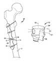
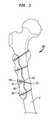
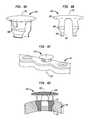
- FIG. 1is a perspective view of one embodiment of a fixation system of the present invention that conceptually shows a cable plug securing a surgical cable to a bone plate.
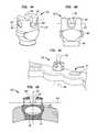
- FIG. 2Ais a perspective view a cable plug in accordance with the present invention, wherein the cable plug has an aperture and an interior conduit.
- FIG. 2Bis a profile view of the cable plug shown in FIG. 2A .
- FIG. 2Cis a perspective view of the cable plug shown in FIG. 2B , wherein the cable plug is engaged with an aperture in the bone plate.
- FIG. 2Dis a cross-sectional view of the cable plug shown in FIG. 2C .
- FIG. 3Ais a perspective view of another embodiment of a cable plug, wherein the cable plug has an enlarged top surface and an interior conduit.
- FIG. 3Bis a profile view of the cable plug shown in FIG. 3A .
- FIG. 3Cis a perspective view of the cable plug shown in FIG. 3B , wherein the cable plug is engaged with an aperture in the bone plate.
- FIG. 3Dis a cross-sectional view of the cable plug shown in FIG. 3C .
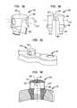
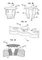
- FIG. 4Ais a perspective view of another embodiment of a cable plug, wherein the cable plug has an aperture intersected by an upward facing channel.
- FIG. 4Bis a profile view of the cable plug shown in FIG. 4A .
- FIG. 4Cis a perspective view of the cable plug shown in FIG. 4B , wherein the cable plug is engaged with an aperture in the bone plate and tilted relative thereto.
- FIG. 4Dis a cross-sectional view of the cable plug shown in FIG. 4A .
- FIG. 5Ais a perspective view of another embodiment of a cable plug, wherein the cable plug has an interior conduit in the form of a downward facing channel.
- FIG. 5Bis a profile view of the cable plug shown in FIG. 5A .
- FIG. 5Cis a perspective view of the cable plug shown in FIG. 5B , wherein the cable plug is engaged with an aperture in the bone plate.
- FIG. 5Dis a cross-sectional view of the cable plug shown in FIG. 5A .
- FIG. 6Ais a perspective view of another embodiment of a cable plug, wherein the cable plug has an enlarged top surface and an interior conduit.
- FIG. 6Bis a profile view of the cable plug shown in FIG. 6A .
- FIG. 6Cis a perspective view of the cable plug shown in FIG. 6B , wherein the cable plug is engaged with an aperture in the bone plate.
- FIG. 6Dis a cross-sectional view of the cable plug shown in FIG. 6A .
- FIG. 7Ais a perspective view of another embodiment of a cable plug, wherein the cable plug has an interior conduit in the form of a downward facing channel with a bulbous portion.
- FIG. 7Bis a profile view of the cable plug shown in FIG. 7A .
- FIG. 7Cis a perspective view of the cable plug shown in FIG. 7B , wherein the cable plug is engaged with an aperture in the bone plate.
- FIG. 7Dis a cross-sectional view of the cable plug shown in FIG. 7A .
- FIG. 8Ais a perspective view of another embodiment of a cable plug, wherein the cable plug has an enlarged top surface and an interior conduit with a bulbous portion.
- FIG. 8Bis a profile view of the cable plug shown in FIG. 8A .
- FIG. 8Cis a perspective view of the cable plug shown in FIG. 8B , wherein the cable plug is engaged with an aperture in the bone plate.
- FIG. 8Dis a cross-sectional view of the cable plug shown in FIG. 8A .
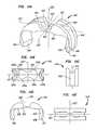
- FIG. 9Ais a perspective view of another embodiment of a cable plug that has a cable retaining arm with an aperture having a substantially circular opening.
- FIG. 9Bis a profile view of the cable plug shown in FIG. 9A .
- FIG. 9Cis a perspective view of the cable plug shown in FIG. 9B , wherein the cable plug is engaged with an aperture in the bone plate.
- FIG. 9Dis a cross-sectional view of the cable plug shown in FIG. 9A .
- FIG. 10Ais a perspective view of another embodiment of a cable plug that has a cable retaining arm with an aperture having a semi-circular opening.
- FIG. 10Bis a profile view of the cable plug shown in FIG. 10A .
- FIG. 10Cis a perspective view of the cable plug shown in FIG. 10B , wherein the cable plug is engaged with an aperture in the bone plate.
- FIG. 10Dis a cross-sectional view of the cable plug shown in FIG. 10A .
- FIG. 11Ais a perspective view of another embodiment of a cable plug, wherein the cable plug has a “V” shaped profile.
- FIG. 11Bis a profile view of the cable plug shown in FIG. 11A .
- FIG. 11Cis a perspective view of the cable plug shown in FIG. 11B , wherein the cable plug is engaged with an aperture in the bone plate.
- FIG. 11Dis a cross-sectional view of the cable plug shown in FIG. 11A .
- FIG. 12Ais a perspective view of another embodiment of a cable plug, wherein the cable plug has a top surface of that is convexly shaped and an interior conduit in the form of a downward facing channel with a bulbous portion.
- FIG. 12Bis a profile view of the cable plug shown in FIG. 12A .
- FIG. 12Cis a perspective view of the cable plug shown in FIG. 12B , wherein the cable plug is engaged with an aperture in the bone plate.
- FIG. 12Dis a cross-sectional view of the cable plug shown in FIG. 12A .
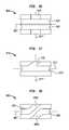
- FIG. 13Ais a profile view of another embodiment of a cable plug, wherein the cable plug has an interior conduit with a bulbous portion and a chamfered entry portion.
- FIG. 13Bis a side view of the cable plug shown in FIG. 13A .
- FIG. 13Cis a top view of the cable plug shown in FIG. 13B .
- FIG. 13Dis a cross-sectional view of the cable plug shown in FIG. 13A , wherein the cable plug is engaged with an aperture in the bone plate.
- FIG. 14Ais a perspective view of a cable attachment plate in accordance with the present invention.
- FIG. 14Bis a cross-sectional view of the cable attachment plate shown in FIG. 14A .
- FIG. 14Cis a side view of the cable attachment plate shown in FIG. 14A .
- FIG. 14Dis profile view of the cable attachment plate shown in FIG. 14A .
- FIG. 14Eis top view of the cable attachment plate shown in FIG. 14A .
- FIG. 15Ais a perspective view of another embodiment of the cable attachment plate shown in FIG. 14A .
- FIG. 15Bis a cross-sectional view of the cable attachment plate shown in FIG. 15A .
- FIG. 15Cis a side view of the cable attachment plate shown in FIG. 15A .
- FIG. 15Dis profile view of the cable attachment plate shown in FIG. 15A .
- FIG. 15Eis top view of the cable attachment plate shown in FIG. 15A .
- FIG. 16is a top view of another cable attachment plate, wherein the plate has a plurality of channels.
- FIG. 17is a top view of another cable attachment plate, wherein the plate has a redirecting feature.
- FIG. 18is a top view of another cable attachment plate that has a plurality of redirecting features.
- FIG. 19is a perspective view of an exemplary system in accordance with the present invention.
- FIG. 20is a perspective view of another exemplary system in accordance with the present invention.
- proximalmeans closer to the heart; “distal” means more distant from the heart; “inferior” means toward the feet; “superior” means towards the head; “anterior” means towards the front part of the body or the face; “posterior” means towards the back of the body; “medial” means toward the midline of the body; and “lateral” means away from the midline of the body.
- first and second lateral axesmight alternatively be described as, respectfully, an anterior-posterior axis and a medial-lateral axis. Accordingly, a local Cartesian coordinate system is established with respect to a bone and hereby introduced.
- the present inventionmay be rotated about any equivalent longitudinal axis, or be positioned at any angle relative to either the first or second lateral axis, these descriptors are merely exemplary not intended to limit the present invention to a particular orientation.
- Bone fixation system 100engaged to a portion of a femur bone 12 .
- Bone fixation system 100includes a surgical cable 61 coupled to a bone plate 60 via a cable plug 110 .
- a portion of surgical cable 61is wrapped around femur bone 12 just above the lesser trochanter, while another portion of surgical cable 61 is wrapped around the femoral shaft just below the lower trochanter, and two more portions of surgical cable 61 are wrapped about the femoral shaft some distance below the lesser trochanter.
- Surgical cable 61may be embodied as one or more cable wires that are received and retained by one or more cable plugs 110 at a plurality of angles relative to a longitudinal axis of bone 12 .
- each of a plurality of cable plugs 110is located in an aperture 62 of bone plate 60 such that bottom portion of plug 110 is adjacent femur bone 12 .
- Each cable plug embodiment disclosed in this applicationpreferably has a cable retaining portion and a fastening portion.
- cable plug 110has a cable retaining portion 120 and a fastening portion 140 .
- cable retaining portion 120may have a channel or aperture adapted to receive the cable wire.
- the cable retaining portion 120has two cable receiving members that project upwardly or downwardly from a base surface of cable plug 110 to form a channel, interior conduit, or passage within the interior conduit.
- Any cable retaining portion described hereinmay also have a single cable receiving member.
- each cable receiving memberhas an outer face adapted to be grasped by the fingers of a user so that cable plug 110 is easily manipulated by hand.
- cable retaining portion 120is integral with the fastening portion 140 (conceptually illustrated in dashed lines).
- An outer circumference of fastening portion 140may be threaded; in some embodiments, this outer circumference is interrupted by an interior conduit, as noted below.
- cable plug 110is pressed into aperture 62 of bone plate 60 until a bottom surface of fastening portion 140 is adjacent bone plate 60 . This permits rotation of cable plug 110 with respect to bone plate 60 in a first or second direction about a longitudinal axis of cable plug 110 .
- surgical cable 61may be retained within cable retaining portion 120 and oriented a plurality of angles relative to the bone 12 .
- FIGS. 2A-13DNumerous cable plug embodiments are disclosed in FIGS. 2A-13D . Where similar components to those of cable plug 110 are included in a cable plug 210 , 310 , 410 , etc., similar reference numerals are utilized, but within that series of numbers.
- another embodiment of cable plug 110is depicted in FIGS. 2A-D as a cable plug 210 . Similar to above, cable plug 210 has a cable retaining portion 220 integral with a fastening portion 240 . Cable plug 210 may also be described as having an intermediate portion 280 located between cable retaining and fastening portions 220 and 240 . Desirably, each portion of cable plug 210 is disposed along a longitudinal axis 252 in FIGS. 2A-D . As disclosed with respect to the embodiments set forth below, each portion of the cable plug works to reduce the potential shear stresses and strains that may be transferred to surgical cable 61 by enhancing the flexibility and resiliency of plug 210 .
- cable retaining portion 220has an outer diameter less than or equal to an outer diameter of aperture 62 in bone plate 60 .
- a top surface 229 of cable plug 210is curved. Alternatively, this top surface may be flat, substantially flat, or any combination thereof.
- a top surface 1229 of a cable plug 1210is convexly shaped, as shown in FIG. 12A .
- a cable plug 1310has a top surface 1329 that is curved to reduce the prominence of a cable retaining portion 1320 with respect to the exterior surface of bone plate 60 , as in FIGS. 13A-D .
- top surface 229is depicted as being smooth, any embodiment of this top surface may be dimpled, medicated, or have an otherwise variable finish. Still other variations of the cable retaining portion are contemplated.
- a cable plug 310has a top surface 329 with an outer diameter larger than the outer diameter of aperture 62 , thus giving a cable plug 310 a substantially “1” shaped profile.
- a top surface 429 of FIG. 4Ais broken by a channel 426 ′′ extending along second lateral axis 427 ′′.
- Channel 426 ′′desirably opens upwardly along a longitudinal axis 452 towards top surface 429 .
- each of the two cable retaining members forming channel 426 ′′are intersected by an aperture 426 ′.
- Cable retaining portion 220may incorporate a variety of cable receiving means.
- cable retaining portion 220 of FIG. 2Dhas an aperture 226 ′ extending along a first lateral axis 227 ′.
- Aperture 226 ′receives cable 61 within cable retaining portion 220 .
- aperture 226 ′has a substantially circular opening with beveled edges; although non-circular openings and varied edge treatments are possible.
- first lateral axis 227 ′is substantially parallel with bottom surface 242 of cable plug 210 .
- a first lateral axis 1227 ′may be angled with respect to a bottom surface 1242 of cable plug 1210 so as to receive cable wire 61 at a pre-determined angle therealong.
- FIGS. 4A-Ddepicts a channel 426 ′′ that extends along a second lateral axis 427 ′′ and is intersected by an aperture 426 ′ extending along a first lateral axis 427 ′.
- channel 426 ′′desirably opens upwardly along a longitudinal axis 452 towards top surface 429 . This enables the method step of wrapping cable wire 61 around the bone plate, through channel 426 ′′, and then through aperture 426 ′ to secure cable wire 61 within cable retaining portion 420 .
- an aperture 526 ′ of a cable plug 510is intersected by or in communication with a portion of an interior conduit 581 .
- interior conduit 581is defined by a pair of first and second sidewalls 582 and 583 .
- sidewalls 582 and 583act as pair of first and second biased legs that form interior conduit 581 .
- a passage 526 ′′extends through cable plug 510 along a second lateral axis 527 ′′ to form at least a portion of conduit 581 .
- Interior conduit 581opens downwardly along a longitudinal axis 552 towards a fastening portion 540 of plug 510 .
- the aperture described abovemay be omitted. For example, in FIGS.
- a cable plug 1310has a passage 1326 ′′ that extends along a second lateral axis 1327 ′′ to form a portion of an interior conduit 1381 .
- passage 1326 ′′serves as the only cable receiving means adapted to receive cable wire 61 .
- the structure of plug 1310permits the method step of pushing cable plug 1310 into aperture 62 to receive a portion of cable wire 61 within passage 1326 ′′ of interior conduit 1381 .
- the features of plug 1310might alternatively be included within any embodiment of cable plug 110 described herein.
- the cable retaining portionmay also have one or more cable retaining arms extending outwardly therefrom.
- FIGS. 9A-Dshow at least one cable retaining arm 970 extending from a surface of a cable retaining portion 920 of cable plug 910 .
- each arm 970has a top surface 971 contiguous with a top surface 929 of cable plug 910 .
- a cable retaining meanssuch as aperture 974 , for example, is attached to cable retaining portion 920 .
- aperture 974is depicted as having a substantially circular opening.
- an aperture 1074may be similar to aperture 974 , except for having a semi-circular opening, as shown in FIG. 10B .
- Aperture 1074may also be adapted to capture a portion of cable wire 61 .
- the open portion of aperture 1074may be slightly less than the width of cable wire 61 so that wire 61 may be snapped into aperture 1074 .
- a cable retaining portion 1120 of a cable plug 1110is divided by a channel 1126 ′ along a first lateral axis 1127 ′.
- channel 1126 ′opens upwardly along a longitudinal axis 1252 towards a cable retaining portion 1120 .
- This configurationbestows plug 1110 with a “V” shaped profile.
- At least one cable retaining arm 1170extends directly from either divided part of cable retaining portion 1120 .
- Cable plug 1110 of FIGS. 11A-Dmay be engaged with aperture 62 in accordance with any engagement mode set forth herein. As shown in FIG.
- cable plug 1110has two cable retaining arms 1170 extending therefrom, each having aperture for receiving wire 61 .
- Plug 1110might also comprise a plurality of cable retaining arms, wherein each arm 1170 is oriented transversely with respect to the other.
- intermediate portion 280is also depicted in FIGS. 2A-D , which depicts an interior conduit 281 extending along second lateral axis 227 ′′.
- FIGS. 2A-Ddepict an interior conduit 281 extending along second lateral axis 227 ′′.
- interior conduit 281is an enclosed conduit that is bounded along longitudinal axis 252 by cable retaining portion 220 and fastening portion 240 ; and bounded along first lateral axis 227 ′ by a first sidewall 282 and a second sidewall 283 .
- first and second sidewalls 282 and 283spans between cable retaining portion 220 and fastening portion 240 along longitudinal axis 252 .
- the thickness and profile of sidewalls 282 , 283varies with respect to longitudinal axis 252 .
- the thickness of sidewalls 282 , 283is adapted to provide cable plug 210 with a desired range of flexural characteristics, as discussed further below.
- Interior conduit 281is illustrated as having a substantially cylindrical opening, although the opening may have any geometric shape. Nonetheless, because interior conduit 281 has a substantially cylindrical opening, the interior profile of sidewalls 282 , 283 is substantially curved.
- shape of first and second sidewalls 282 , 283might also vary according to the profile of interior shape 281 , the means for receiving cable member 61 , the material composition of cable plug 210 , or related attributes.
- conduit 1381 of cable plug 1310is open ended.
- conduit 1381is bounded along longitudinal axis 252 by cable retaining portion 1320 and bounded along a first lateral axis 1327 ′ by a first sidewall 1382 and a second sidewall 1383 of an intermediate portion 1380 .
- each of sidewalls 1382 and 1383may be a pair of first and second biased legs that form interior conduit 1381 .
- a passage 1326 ′′forms a portion of interior conduit 1381 .
- the passage 1326 ′′may form a bulbous profile 1387 .
- passage 1326 ′′has a chamfered entry portion, as noted below.
- first and second sidewalls 282 and 283 of cable plug 210have a protrusion 285 extending outwardly therefrom.
- protrusion 285is adapted to engage at least a portion of aperture 62 .
- Cable plug 210may be inserted into aperture 62 of bone plate 60 so that protrusion 285 achieves an interference fit with the interior surfaces of aperture 62 .
- sidewalls 282 and 283may be flexible so that protrusion 285 may be interference fit with aperture 62 when the width of protrusion 285 is slightly greater than the diameter of aperture 62 .
- cable plug 210may be pushed into aperture 62 along longitudinal axis 252 until it is firmly wedged therein.
- at least a portion of cable plug 210may be composed of an elastically deformable material.
- protrusion 285may be deformed into and between threads 63 .
- cable plug 210may be rotatably engaged with aperture 62 .
- a protrusion 685is adapted for receipt within at least one thread 63 of aperture 62 .
- protrusion 685may be screwed into aperture 62 .
- the width of a protrusion 1185may be approximately equal to the maximum dimension of thread 63 so that protrusion 1185 may be pushed over and into thread 63 .
- protrusion 1185is engaged with aperture 62 when protrusion 1185 is snapped therein.
- protrusion 285is shown as being engageable with aperture 62 proximate to the top surface of bone plate 60 , an equivalent protrusion might alternatively be engageable with aperture 62 at any point along longitudinal axis 252 .
- a protrusion 1285comprises a sloped portion of sidewalls 1282 and 1283 that does not extend outwardly therefrom.
- interior conduit 281preferably has a cylindrical shaped opening that extends through intermediate portion 280 along second lateral axis 227 ′′. But of course, the opening of conduit 281 need not be substantially cylindrical or wholly contained within intermediate portion 280 .
- interior conduit 581 of FIGS. 5A-Dforms a downward facing channel that extends through intermediate portion 580 and fastening portion 540 of cable plug 510 .
- interior conduit 581is still formed between cable retaining portion 520 , first and second sidewalls 582 and 583 , and fastening portion 580 .
- a passage 526 ′′forms at least a portion of the interior conduit, as noted above.
- interior conduits described hereinenable a number of important features.
- the elements of intermediate portion 280such as first and second sidewalls 282 and 283 , may flex independently in response to any forces applied thereto by cable wire 61 .
- Thisenables cable plug 210 to resiliently absorb many of the stress and strains that might otherwise cause fastening portion 240 to disengage from aperture 62 during implantation, or cause bone plate 60 to shift during use.
- portions of cable plug 210may flex to engage aperture 62 of bone plate 60 . In some embodiments, this allows cable plug 210 to simultaneously engage aperture 62 and receive cable wire 61 .
- Elements of cable plug 210may be adapted to have varying degrees of biased resiliency.
- cable plug 210may be further adapted to bias first and second sidewalls 282 , 283 , against an interior surface of aperture 62 to further secure cable plug 210 therein.
- cable plug 510may be adapted to bias first and second sidewalls 582 and 583 outwardly against the inner surface of aperture 62 .
- these biasing featuresmay be greatly enhanced when the interior conduit 281 is in communication with aperture 226 ′ because the additional void space allows cable plug 210 to have an expanded range of deformation.
- This biasing forcemay also be enhanced by the material composition of the cable plug, which may be comprised of an inherently resilient material.
- the structure of the interior conduitmay be adapted to enhance the biasing force.
- a cable plug 810may have a passage 826 ′′ with a bulbous profile 887 , as in FIG. 8B , that is adapted to enhance the biasing force.
- interior conduit 281also reduces the frictional forces imposed on cable plug 210 during engagement with aperture 62 simply by reducing the surface area of first and second sidewalls 282 , 283 , and any portions of protrusion 285 extending outwardly therefrom.
- interior conduit 1281 of cable plug 1210is depicted in FIGS. 12A-D as extending a second axis 1227 ′′ that is angled with respect to longitudinal axis 1252 .
- cable plug 1210may be adapted to receive cable wire 61 at a pre-determined angle within aperture 62 .
- Each entrance to interior conduit 281may be further modified to reduce the stresses imposed on cable wire 61 .
- an interior conduit 1381 of cable plug 1310 in FIGS. 13A-Dhas an entry portion 1384 that extends parallel to axis 1352 .
- entry portion 1384is chamfered to prevent cable wire 61 from bending around a hard corner when tightened. Desirably, this further reduces the cross-sectional area of plug 1310 to promote engagement of plug 1310 with aperture 62 of bone plate 60 .
- FIGS. 2A-Ddepicts a fastening portion 240 having an outer circumference 243 , a band 247 , and a bottom surface 242 .
- Band 247preferably extends outwardly from outer circumference 243 to prevent cable plug 210 from lifting out of aperture 62 .
- band 247is an exemplary fastening surface configured to engage at least a portion of aperture 62 .
- band 247may obtain an interference fit with aperture 62 .
- cable plug 210may be snapped into aperture 62 when band 247 is pushed over and into thread 63 .
- a cable plug 710has a band 747 that may be rotatably engaged with aperture 62 , as in FIGS. 7A-D .
- band 247 of FIG. 2Bhas a curved fastening surface that is symmetrical about axis 252 . This allows band 247 to slide over each thread 63 as cable plug 210 is inserted into aperture 62 .
- a band 847may be asymmetrical about axis 852 . This allows at least a portion of band 847 to be a thread-like element that is angled to engage threads 63 .
- a band 1347may be an asymmetrical element that is divided into a first band element 1347 A opposite of a second band element 1347 B with respect to interior conduit 1381 .
- thisfurther secures cable plug 1310 in aperture 62 of bone plate 60 by permitting each of the band elements 1347 A and 1347 B to engage separate portions of thread 63 .
- Band 747may also be omitted.
- fastening portion 1140 of FIGS. 11A-Dis constructed without an equivalent band 747 .
- cable plug 1110is secured to bone plate 60 by protrusion 1185 .
- either of the intermediate or fastening portions of the cable plugmay be further adapted to receive a surgical wire 61 , preferably within passage 526 ′′.
- a portion of interior conduit 1381has a chamfered portion 1386 that chamfers away from axis 1352 and towards the outer surfaces of fastening portion 1340 .
- thisprevents cable wire 61 from being exposed to a hard corner and aids in capturing wire 61 in passage 1327 ′′.
- any embodiment of the interior conduit, such as conduit 281may also be adapted to receive wire 61 therein.
- each cable plug disclosed abovemay also be incorporated into a cable collar or attachment plate in accordance with the present invention.
- Exemplary embodiments of the cable attachment plateare depicted in FIGS. 14-15 as plates 1410 and 1510 .
- cable attachment plate 1410similar to cable plug 110 , 210 , 310 , etc., also has a cable retaining portion 1420 integral with a fastening portion 1440 .
- Each of the cable retaining and fastening portions 1420 and 1440are disposed along a longitudinal axis 1452 . Similar to above, each of these portions work in combination to reduce the potential shear stresses and strains that may be transferred to surgical cable 61 during implantation or use.
- a cable retaining portion 1420 of attachment plate 1410has a first channel 1426 ′ for receiving cable wire 61 along a portion of an axis 1427 ′.
- First channel 1426 ′is at least partially defined by at least two cable receiving members 1424 and 1425 that extend upwardly from a base surface of cable retaining portion 1420 .
- Cable retaining portion 1420also has a second channel 1426 ′′ extending therethrough along a second axis 1427 ′′ that is transverse with longitudinal axis 1452 . This allows cable wire 61 to be wrapped through or out of second channel 1426 ′′, as needed, to secure bone plate 60 to bone 12 .
- second channel 1426 ′′allows cable wire 61 to be wrapped multiple times around bone 12 in a plurality of directions.
- Second channel 1426 ′′cuts through cable retaining members 1424 , 1425 to form a resilient section 1423 of cable attachment plate 1410 . Because it has a reduced cross-sectional area, resilient section 1423 may flex to place cable attachment plate 1410 in contact with bone plate 60 .
- the rigidity, or inversely the flexibility, of resilient section 1423is directly attributable to the material composition of plate 1410 and the cross-sectional area of resilient section 1423 .
- an interior perimeter 1428surrounds resilient section 423 and a portion of second channel 1426 ′′.
- Perimeter 1428is depicted as having rectangular shape, although any regular or irregularly shape is possible. Thus, even if the material composition of plate 1410 is rigid or semi-rigid, resilient section 1423 will remain flexible.
- Cable attachment plate 1410also has a fastening portion 1440 disposed opposite of cable retaining portion 1420 along longitudinal axis 1452 of the plate 1410 .
- fastening portion 1440comprises a pair of first and second sidewalls 1482 and 1483 that are configured to move in a direction toward and a direction away from the longitudinal axis 1452 . This movement preferably allows at least an interior portion of first and second sidewalls 1482 , 1483 to contact an outer surface of bone plate 60 when cable attachment plate 1410 is operatively coupled to bone plate 60 .
- each first or second sidewall 1482 , 1483may be composed of an elastically deformable material adapted to flex, as needed, to ensure contact with the outer surface of bone plate 60 .
- sidewalls 1482 , 1483may flex to accommodate the contours of any embodiment of bone plate 60 .
- Bone plate contacting surface 1454is a continuous surface formed by the underside cable retaining portion 1420 and the interior surfaces of each of sidewalls 1482 , 1483 .
- Bone plate contact surface 1454may be further adapted to engage the exterior surface of bone plate 60 .
- surface 1454may be a smooth surface adapted to loosely grip the exterior surface of bone plate 60 so that its final position is influenced by the tightening of cable wire 61 .
- surface 1454may be undulating, intentionally roughened, or otherwise treated, to frictionally engage the exterior surface of bone plate 60 .
- bone plate contacting surface 1454has at least one protrusion 1455 extending outwardly from surface 1454 to contact the outer surface of bone plate 60 .
- Protrusion 1455may be any known shape with any known surface treatment.
- protrusion 1455is shown as being pointed element in FIG. 14D ; however, protrusion 1455 may also have a rounded surface, any portion of which may be further adapted to frictionally engage the exterior surface of bone plate 60 .
- Bone plate contacting surface 1454may also have a pair of first protrusions 1455 A and 1455 B opposite of a pair of second protrusions 1455 C and 1455 D, as shown, for example, in FIG. 14B .
- each pair of protrusions, 1455 A-Dis arranged to provide four distinct points of contact with bone plate 60 .
- Each point of contactmay be arranged about interior perimeter 1428 of cable retaining portion 1420 in a regular or irregular manner.
- each point of contactis located proximate to a corner of interior perimeter 1428 in FIG. 14B and, thereby, arranged in regular manner about interior perimeter 1428 .
- each contactmay be irregularly arranged on bone plate contacting surface 1454 to promote four points of contact with the exterior surface of an irregularly shaped bone plate 60 .
- each embodiment of at least one protrusion 1455 disclosed hereinalso allow portions of cable attachment plate 1410 to conform to the exterior surface of bone plate 60 .
- interior perimeter 1428may surround resilient section 1423 so that each protrusion 1455 serves as an integral fulcrum to distribute forces within plate 1410 . This ensures that sidewalls 1482 , 1483 will flex in a pre-determined manner.
- This configurationalso allows each protrusion 1455 to transfer any compressive loads applied wire 61 during tightening, and yet also allows another portion of plate 1410 , such as resilient section 1423 or sidewalls 1482 , 1483 , to flexibly conform to the exterior surface of bone plate 60 .
- bone plate contact surface 1454preferably has at least one contact anchor 1456 extending away from an end portion of at least one of sidewalls 1482 , 1483 along first axis 1427 ′.
- Each contact anchor 1456is preferably adapted to contact the exterior surface of bone plate 60 .
- each contact anchor 1456 on plate 1410 in FIGS. 14A-Ehas a triangular shape adapted for three point contact with the exterior surface of bone plate 60 .
- any surface on contact anchor 1456may be smooth or rough, like that of bone plate contacting surface 1454 , or protrusions 1455 , so as to promote contact with bone plate 60 .
- first channel 1426 ′ and each contact anchor 1456combine to form a first cross-sectional area 1457 A opposite of a second cross-sectional area 1457 B.
- the varied shapes of cross-sectional area 1457 A and 1457 Bfacilitate placement of cable attachment plate 1410 .
- each of first and second cross-sectional areas 1457 A and 1457 Bmay be shaped to match the exact surface contours of bone plate 60 .
- attachment plate 1410may be placed in contact with bone plate 60 by sliding the interior surfaces of cross-sectional areas 1457 A and 1457 B along the exterior surface of bone plate 60 in a direction that is substantially parallel to axis 1452 .
- attachment plate 1410is formed of a rigid material, such as metal
- plate 1410can be slide into position along axis 1452 .
- Areas 1457 A and 1457 Balso allow plate 1410 to be rotated onto the bone plate about axis 1427 ′.
- the rounded point of area 1457 Bmay be placed against the exterior surface of the bone plate so that the planar area of 1457 A can be rotated about second axis 1427 ′′ to be slid around and along the exterior surface of plate 60 .
- Each contact anchor 1456is also adapted to facilitate removal of cable attachment plate 1410 from bone plate 60 .
- each contact anchor 1456chamfers away from longitudinal axis 1452 to define a bottom edge 1457 of fastening portion 1440 . This forms a space between bottom edge 1457 and the exterior surface of bone plate 60 . Because of this space, a removal force may be applied to edge 1457 to de-couple attachment plate 1410 from bone plate 60 by prying one of sidewalls 1482 or 1483 away the exterior surface of plate 60 .
- elements of cable receiving members 1424 , 1425 of cable retaining portion 1420may be varied to provide various modes of securing cable wire 61 to bone plate 60 .
- cable receiving members 1424 and 1425are separated by a width along second axis 1427 ′′ that is equal to or greater than the diameter of cable wire 61 . This allows cable wire 61 to move freely in and out of first channel 1426 ′.
- cable receiving members 1424 and 1425are separated by a width along second axis 1427 ′′ that is slightly less than the diameter of cable wire 61 . Thus, if only one of members 1424 or 1425 is flexible, then cable wire 61 may still be passed therebetween.
- an alternate cable attachment plate 1510may have a first channel 1526 ′ that is at least partially enclosed.
- plate 1510has a pair of enclosed portions 1536 .
- Each enclosed portion 1536has an aperture 1574 that extends through a portion of cable attachment plate 1510 .
- aperture 1574is formed by spanning a cross member 1575 between each of cable receiving members 1524 and 1525 along second axis 1527 ′′. This allows cable wire 61 to be threaded through aperture 1574 as it is wrapped around bone plate 60 .
- first channel 1526 ′may have a width equal to or greater than the diameter of cable wire 61 .
- at least a narrowed portion 1539 of first channel 1526 ′may be separated by a width that is slightly less than the width of cable wire 61 so that it may be secured therein in the manner described above.
- first channels 1426 ′ or 1526 ′may also vary.
- both of channels 1426 ′ and 1526 ′are depicted in FIGS. 14A-15E as extending around cable retaining portion 1420 and fastening portion 1440 to form a continuous channel element that runs the length of attachment plate 1410 .
- an exemplary embodiment of channel 1426 ′may only wrap around a portion of cable retaining portion 1420 or fastening portion 1440 .
- a plurality of first channels 1626 ′may also be incorporated into a plate 1610 so that wire 61 can be wrapped around bone plate 60 multiple times.
- FIG. 16a plurality of first channels 1626 ′ may also be incorporated into a plate 1610 so that wire 61 can be wrapped around bone plate 60 multiple times.
- a first channel 1726 ′may have a redirecting feature 1785 adapted to direct cable wire 61 out of a channel 1726 ′ along at least one direction transverse to first axis 1727 ′.
- a first channel 1826 ′may be bifurcated to have to two redirecting features 1885 A and 1885 B. This allows cable wire 61 to be wrapped in plate 1810 in a first direction and redirected out of plate 1810 in a second direction so that plate 1810 may be used to reverse the course of wire 61 as it is wrapped around bone plate 60 .
- the base surface of channel 1426 ′may be made from a resilient material, while each cable receiving member 1424 or 1425 is made of a rigid or semi-rigid material. This allows distinct portions of plate 1410 to change shape in response to compressive forces applied by tightening wire 61 .
- an elongated spring-like elementmay be formed into the base surface along first axis 1427 ′ to impart a desired resiliency into cable attachment plate 1410 .
- the elongated spring-like elementmay be used to enhance the biasing forces applied by plate 1410 to an exterior surface of bone plate 60 .
- the elongated spring-like elementmay be any resilient or biasing element that is imbedded in the base surface along a length parallel to bone plate contact surface 1454 so as to bias sidewalls 1482 , 1483 towards or away from longitudinal axis 1452 .
- the spring-like elementmay run the entire length of first channel 1426 ′.
- Sidewalls 1482 and 1483may be biased, as noted above.
- at least one sidewallmay be biased to apply a compressive force against the exterior surface of bone plate 60 .
- the biasing forcemay be imparted by the material composition and cross-section area of sidewalls 1482 , 1483 .
- the spring-like element described abovemay be embedded within sidewalls 1482 and 1483 at a location proximate to bone plate contact surface 1545 to impart the biasing force.
- the biasing forcemay be imparted to sidewalls 1482 , 1483 by resilient section 1423 . As further shown in FIG.
- the underside of resilient section 1423is formed or scored with a flexural feature 1429 adapted to ensure that sidewalls 1482 , 1483 bend or flex in a pre-determined manner. This also ensures that first channel 1426 ′ is rigid enough to withstand the forces applied by cable wire 61 as it is tightened, yet flexible enough to conform to any bone plate 60 .
- flexural feature 1429may vary.
- Elements of plate 1410 and bone plate 60may also be modified to promote contact with cable attachment plate 1410 .
- the exterior surface of bone plate 60may, for example, have at least one notch adapted to receive at least a portion of contact anchor 1456 therein. In this configuration, contact anchor 1456 is received in the notch to lock plate 1410 against bone plate 60 .
- First and second sidewalls 1482 and 1483may be biased to reinforce this locking mechanism.
- anchor 1456may have grasping portion that extends out from bone plate contacting surface 1454 to engage the underside of bone plate 60 . Similar to above, this provides an alternate means of locking plate 1410 against bone plate 60 .
- the perimeter of bone plate 60may also vary.
- bone plate 60may have a rectangular shape, in which case, each contact anchor 1456 may have a cross section 1457 adapted to engage the relatively flat surfaces of a rectangular shaped bone plate 60 .
- bone plate 60may have an undulating perimeter that defines at least two bulbous portions 60 A and 60 B.
- each contact anchor 1456may have a cross-section 1457 adapted for receipt between the exterior surfaces of bone plate 60 that are defined by the intersection of bulbous portions 60 A and 60 B.
- thisallows each contact anchor 1456 to be wedged against the exterior surface of bone plate 60 when plate 1410 is mounted thereto.
- FIGS. 4A-DA number of method steps are also contemplated as part of the present invention, each of which is enabled by the descriptions of each cable plug or cable attachment plate set forth above.
- a first exemplary methodis enabled by FIGS. 4A-D .
- this first methodcomprises the steps of: engaging cable plug 410 within aperture 62 ; wrapping a cable wire 61 around bone plate 60 ; and receiving wire 61 within at least one cable receiving means of cable 410 to secure bone plate 60 to bone 12 .
- the cable wire 61is received within a first cable receiving means along first axis 427 ′ and a second cable receiving means along second axis 427 ′′.
- the first cable receiving meansmay comprise channel 426 ′, while the second cable receiving means comprises aperture 426 ′′.
- This exemplary methodmay further comprise the steps of securing cable wire 61 within the first or second receiving means and tightening the surgical wire to cause cable plug 410 to engage with aperture 62 .
- a final stepmay comprise fastening the cable wire 61 to itself or a portion of bone plate 60 to maintain a pre-determined tensile force within cable wire 61 . Additional fastening hardware may also be included in this step.
- FIGS. 5A-DA second exemplary method is enabled, for example, by FIGS. 5A-D .
- this second embodimentcomprises the steps of: wrapping a cable wire 61 around bone plate 60 so that a portion of cable wire 561 is adjacent to aperture 62 ; locating first sidewall 582 and second sidewall 583 of interior conduit 581 of cable plug 510 on either side of cable wire 61 ; and engaging fastening portion 540 with an interior surface of aperture 62 .
- Engaging fastening portion 540desirably causes cable wire 61 to be received within interior conduit 581 .
- cable plug 510is secured within passage 526 ′′ when fastening portion 540 is engaged with aperture 62 .
- cable wire 61may contact an interior surface of interior conduit 581 located between sidewalls 582 , 583 .
- this methodpermits the application of a downward force onto cable retaining portion 520 of cable plug 510 to secure cable 61 to the bone plate 60 in a single step.
- a first exemplary methodis enabled, for example, by FIGS. 14A-E .
- This methodcomprises the step of placing bone plate contact surface 1454 of attachment plate 1410 in contact with bone plate 60 . Bone plate 60 is then placed in contact with bone 12 . Once plates 1410 and 60 are proximate to bone 12 , then cable wire 61 may be received in at least first channel 1426 ′ of cable retaining portion 1420 of plate 1410 . Cable wire 61 is then wrapped around bone 12 , bone plate 60 , and cable attachment plate 1410 , as needed, to secure bone plate 60 to bone 12 .
- cable wire 61is then tightened along its longitudinal axis to place at least a portion of the first and second sidewalls in contact with the exterior surface of bone plate 60 when the attachment plate 1410 is operatively coupled to bone plate 60 .
- cable wire 61may be fastened, as noted above.
- any of these exemplary method stopsmay also be modified in accord with each embodiment of the cable attachment plates disclosed herein.
- portions of sidewalls 1482 , 1483such as contact anchor 1456 , may have a cross-sectional area 1457 adapted to match the contours of the exterior surface of bone plate 60 .
- the step of placing contact surface 1454 adjacent bone plate 60may include the step of sliding plate 1410 along axis 1452 until contact surface 1454 is adjacent plate 60 .
- the placement stepmay include the step of placing contact anchor 1456 A against the exterior surface of bone plate 60 and then rotating contact anchor 1456 B into its contact position.
- the step of receiving cable wire 61may further include the step of threading wire 61 through aperture 1574 .
- the step of wrapping cable 61may also include the step of receiving a portion of cable wire 61 in curved feature 1685 so as direct that portion of cable wire 61 out of attachment plate 1610 .
- these method stepsmay further include the step of clamping cable wire 61 to itself, or to bone plate 60 , to retain the tensile forces applied to wire 61 .
- any combination of cable plugs and a cable attachment plates disclosed hereinmay also including a cable wire retention system in accordance with the present invention.
- Exemplary system componentsare illustrated include any elements depicted in FIGS. 1-20 , although numerous additional systems might be equally described, in detail, based upon the structural descriptions within this disclosure
- a system 1900is depicted in FIG. 19 as including cable wire 61 ; bone plate 60 , which has an exterior surface; an embodiment of an attachment plate 1410 (shown partially in section view); and an embodiment of attachment plate 1510 .
- this exemplary system 1900may include any embodiment of cable plug or cable wire attachment plate disclosed herein.
- system 1900may include at least one of any cable wire attachment plate 1410 or 1510 , each having a cable retaining portion 1420 or 1520 and a fastening portion 1440 or 1540 .
- the cable attachment platemay have at least one channel for receiving a cable wire therein, similar to first channels 1426 ′ or 1526 ′.
- the fastening portionmay be disposed from the cable retaining portion about a longitudinal axis, such as axis 1452 or 1552 , or their equivalents.
- the fastening portionmay have a pair of first and second sidewalls, like sidewalls 1482 , 1483 , that are configured to move in a direction toward and a direction away from the longitudinal axis 1452 .
- system 1900permits cable wire 61 to be secured to bone plate 60 by the attachment plate when the at least one protrusion is adjacent the exterior surface of the bone plate.
- FIG. 20depicts an alternate system 2000 in accordance with the present invention.
- this alternate system 2000further comprises at least one cable plug 210 , or other cable plug embodiment.
- a first portion of cable wire 61is secured to bone plate 60 by cable attachment plate 1510
- a second portion of cable wire 61is secured to bone plate 60 by cable plug 210 .
- thisallows one or more portions of cable wire 61 to be secured at multiple points along the length of bone plate 60 .
- system 2000advantageously permits bone plate 60 to be secured to bone 12 by cable wire 61 at various points along the longitudinal axis of femur bone 12 .
- the cable retaining portion of any cable attachment plate in either of systems 1900 or 2000may be adapted to secure cable wire 61 to bone plate 60 by any means described above.
- the at least two cable receiving members 1424 and 1425 that form first channel 1426 ′may be separated by a width equal to or greater than the diameter of cable wire to facilitate the tightening of cable wire 61 .
- Cable receiving members 1424 , 1425may be adapted to secure a portion of cable 61 therebetween.
- Cable wire 61may also be threaded through an enclosed portion, such as aperture 1574 of plate 1510 .
- cable wire 61is wrapped around the various elements of this system 2000 in a first direction and then redirected by the cable attachment plate.
- cable wire 61may be redirected to engage cable plug 210 disposed remotely therefrom along a longitudinal axis of bone plate 60 .
- Cable wire 61may be wrapped in the first direction to encircle an end plate embodiment of the cable attachment plate, such as plate 1710 in FIG. 16B , and then redirected by feature 1785 in a second direction opposite of the first direction.
- either of these configurationsallows the opposing ends of wire 61 to be fastened proximate to a common end of bone plate 60 .
- any combination of cable wires, cable plugs, cable attachment plates, bone plates, or related hardwaremay also be arranged to define a cable fixation kit.
- a kitmay comprise one or more fixed lengths of cable wire 61 , a bone plate 60 adapted for contact with bone 12 , at least one cable plug, such as plug 210 , and at least one cable attachment plate, such as plate 1410 .
- Additional fixation elementssuch as bone screws, cable clamps, or like hardware, may also be included in the invented kit.
- each element of this kitmay be secured in a container.
- the entire kit and its contentsmay be autoclavable or otherwise adapted for sterilization using any known methods.
Landscapes
- Health & Medical Sciences (AREA)
- Orthopedic Medicine & Surgery (AREA)
- Surgery (AREA)
- Life Sciences & Earth Sciences (AREA)
- Heart & Thoracic Surgery (AREA)
- Nuclear Medicine, Radiotherapy & Molecular Imaging (AREA)
- Engineering & Computer Science (AREA)
- Biomedical Technology (AREA)
- Medical Informatics (AREA)
- Molecular Biology (AREA)
- Animal Behavior & Ethology (AREA)
- General Health & Medical Sciences (AREA)
- Public Health (AREA)
- Veterinary Medicine (AREA)
- Neurology (AREA)
- Surgical Instruments (AREA)
Abstract
Description
Claims (20)
Priority Applications (2)
| Application Number | Priority Date | Filing Date | Title |
|---|---|---|---|
| US14/657,188US10499968B2 (en) | 2014-08-08 | 2015-03-13 | Cable plugs for bone plates |
| EP15002307.5AEP2982322B1 (en) | 2014-08-08 | 2015-08-03 | Cable plugs for bone plates |
Applications Claiming Priority (3)
| Application Number | Priority Date | Filing Date | Title |
|---|---|---|---|
| US201462035074P | 2014-08-08 | 2014-08-08 | |
| US201462093127P | 2014-12-17 | 2014-12-17 | |
| US14/657,188US10499968B2 (en) | 2014-08-08 | 2015-03-13 | Cable plugs for bone plates |
Publications (2)
| Publication Number | Publication Date |
|---|---|
| US20160038199A1 US20160038199A1 (en) | 2016-02-11 |
| US10499968B2true US10499968B2 (en) | 2019-12-10 |
Family
ID=53886794
Family Applications (1)
| Application Number | Title | Priority Date | Filing Date |
|---|---|---|---|
| US14/657,188Active2036-08-18US10499968B2 (en) | 2014-08-08 | 2015-03-13 | Cable plugs for bone plates |
Country Status (2)
| Country | Link |
|---|---|
| US (1) | US10499968B2 (en) |
| EP (1) | EP2982322B1 (en) |
Cited By (1)
| Publication number | Priority date | Publication date | Assignee | Title |
|---|---|---|---|---|
| US11039825B2 (en)* | 2016-10-25 | 2021-06-22 | DePuy Synthes Products, Inc. | Plate holes suture connection |
Families Citing this family (9)
| Publication number | Priority date | Publication date | Assignee | Title |
|---|---|---|---|---|
| US10213237B2 (en)* | 2014-10-03 | 2019-02-26 | Stryker European Holdings I, Llc | Periprosthetic extension plate |
| KR101625177B1 (en)* | 2016-01-07 | 2016-06-07 | 주식회사 지에스엠코리아 | Implant for fixing the femoral |
| US10251685B2 (en) | 2016-03-17 | 2019-04-09 | Stryker European Holdings I, Llc | Floating locking insert |
| EP3282618A1 (en)* | 2016-08-09 | 2018-02-14 | Panasonic Intellectual Property Corporation of America | Improved initial and retransmissions of data for v2x transmissions |
| EP3357443B1 (en) | 2017-02-03 | 2019-08-21 | Stryker European Holdings I, LLC | Tensioning cable locking device |
| EP3375394B1 (en)* | 2017-03-13 | 2021-10-13 | Biedermann Technologies GmbH & Co. KG | Cable retaining insert and bone plate assembly with such a cable retaining insert |
| GB2586181A (en) | 2019-06-24 | 2021-02-10 | Nextremity Solutions Inc | Fracture fixation system and method |
| US11944364B2 (en)* | 2020-04-03 | 2024-04-02 | Orthopedic Designs North America, Inc. | Cable-locking plate with screw |
| JP2022099392A (en)* | 2020-12-23 | 2022-07-05 | ネクストレミティ ソルーションズ インコーポレイテッド | Fracture fixation system and method |
Citations (186)
| Publication number | Priority date | Publication date | Assignee | Title |
|---|---|---|---|---|
| US1025008A (en) | 1911-08-07 | 1912-04-30 | Lucien Luttrell Miner | Brace for fractured bones. |
| US1159863A (en) | 1913-04-25 | 1915-11-09 | John Park | Portable joint for ropes, wire, and the like. |
| US2226393A (en) | 1939-12-11 | 1940-12-24 | Baird Jr | Wire clamp |
| US3534731A (en) | 1967-08-18 | 1970-10-20 | Jean Nicolas Muller | Means for joining parts of fractured bones |
| US3547114A (en) | 1967-07-07 | 1970-12-15 | Edward J Haboush | Compensating plate means for bone fractures |
| US3596656A (en) | 1969-01-21 | 1971-08-03 | Bernd B Kaute | Fracture fixation device |
| US3997138A (en) | 1974-06-18 | 1976-12-14 | Henry Vernon Crock | Securing devices and structures |
| US4146022A (en) | 1977-11-16 | 1979-03-27 | Ronald A. Johnson | Fracture fixation by cerclage utilizing cortical bone tack and pull-out tension device |
| EP0075225A2 (en) | 1981-09-18 | 1983-03-30 | Trion Industries, Inc. | Merchandise display hook |
| US4388921A (en) | 1980-05-28 | 1983-06-21 | Institut Straumann Ag | Device comprising a plate and screws for fastening a plate to a bone |
| US4484570A (en) | 1980-05-28 | 1984-11-27 | Synthes Ltd. | Device comprising an implant and screws for fastening said implant to a bone, and a device for connecting two separated pieces of bone |
| US4493317A (en) | 1980-11-20 | 1985-01-15 | Synthes Ltd. (U.S.A.) | Surgical compression plate and drill guide |
| US4641636A (en) | 1983-05-04 | 1987-02-10 | Cotrel Yves P C A | Device for supporting the rachis |
| US4692290A (en) | 1985-11-12 | 1987-09-08 | Celanese Corporation | Process for devolatilizing molten oxymethylene polymer |
| US4794918A (en) | 1985-05-06 | 1989-01-03 | Dietmar Wolter | Bone plate arrangement |
| US4828441A (en) | 1987-07-08 | 1989-05-09 | United Technologies Corporation | Locked threaded insert for high stress application |
| US4867144A (en) | 1986-04-14 | 1989-09-19 | Huta Baildon | Plate for connecting base splinters with bone shafts |
| US4946458A (en) | 1986-04-25 | 1990-08-07 | Harms Juergen | Pedicle screw |
| US4964403A (en) | 1986-12-19 | 1990-10-23 | Huta Baildon Przedsiebiorstwo Panstwowe Katowice | Stabilizer for the treatment of the fracture of the neck and upper metaphysis of the femur |
| US5013313A (en) | 1988-05-30 | 1991-05-07 | Patrick Surer | Device for fixation of part on a support, especially of an implant on a bone |
| US5041113A (en) | 1989-07-20 | 1991-08-20 | Lutz Biedermann | Stabilization member for stabilizing bones |
| US5053036A (en) | 1987-11-03 | 1991-10-01 | Synthes (U.S.A.) | Point contact bone compression plate |
| US5057111A (en) | 1987-11-04 | 1991-10-15 | Park Joon B | Non-stress-shielding bone fracture healing device |
| US5090854A (en) | 1991-03-06 | 1992-02-25 | Artifex Ltd. | Self locking nut |
| US5108399A (en) | 1988-09-17 | 1992-04-28 | Boehringer Ingelheim Gmbh | Device for osteosynthesis and process for producing it |
| US5127914A (en) | 1989-02-10 | 1992-07-07 | Calderale Pasquale M | Osteosynthesis means for the connection of bone fracture segments |
| US5129899A (en) | 1991-03-27 | 1992-07-14 | Smith & Nephew Richards Inc. | Bone fixation apparatus |
| US5147363A (en) | 1989-12-21 | 1992-09-15 | Haerle Anton | Screw for use in osteosynthesis |
| US5151103A (en) | 1987-11-03 | 1992-09-29 | Synthes (U.S.A.) | Point contact bone compression plate |
| US5190545A (en) | 1991-08-27 | 1993-03-02 | Pfizer Hospital Products Group, Inc. | Cerclage wire positioning insert |
| US5209751A (en) | 1992-02-19 | 1993-05-11 | Danek Medical, Inc. | Spinal fixation system |
| US5234431A (en) | 1991-04-03 | 1993-08-10 | Waldemar Link Gmbh & Co. | Bone plate arrangement |
| US5269784A (en) | 1991-12-10 | 1993-12-14 | Synthes (U.S.A.) | Screw nut for plate osteosynthesis |
| US5415658A (en) | 1993-12-14 | 1995-05-16 | Pioneer Laboratories, Inc. | Surgical cable loop connector |
| US5536268A (en) | 1992-12-23 | 1996-07-16 | Plus Endoprothetik Ag | System for osteosynthesis at the vertebral column, connecting element for such a system and tool for its placement and removal |
| US5549608A (en) | 1995-07-13 | 1996-08-27 | Fastenetix, L.L.C. | Advanced polyaxial locking screw and coupling element device for use with rod fixation apparatus |
| US5554157A (en) | 1995-07-13 | 1996-09-10 | Fastenetix, L.L.C. | Rod securing polyaxial locking screw and coupling element assembly |
| US5584834A (en) | 1995-07-13 | 1996-12-17 | Fastenetix, L.L.C. | Polyaxial locking screw and coupling element assembly for use with side loading rod fixation apparatus |
| US5586984A (en) | 1995-07-13 | 1996-12-24 | Fastenetix, L.L.C. | Polyaxial locking screw and coupling element assembly for use with rod fixation apparatus |
| US5607430A (en) | 1995-08-25 | 1997-03-04 | Biomet, Inc. | Bone stabilization implant having a bone plate portion with integral cable clamping means |
| US5618144A (en) | 1995-09-11 | 1997-04-08 | Sigma Tool & Machine | Tee-nut with enlarged barrel end |
| US5643261A (en) | 1994-03-10 | 1997-07-01 | Schafer Micomed Gmbh | Osteosynthesis device |
| US5647873A (en) | 1995-04-13 | 1997-07-15 | Fastenetix, L.L.C. | Bicentric polyaxial locking screw and coupling element |
| US5649927A (en) | 1995-09-27 | 1997-07-22 | Pioneer Laboratories, Inc. | Cable crimp system |
| US5658285A (en) | 1994-10-28 | 1997-08-19 | Jbs S.A. | Rehabitable connecting-screw device for a bone joint, intended in particular for stabilizing at least two vertebrae |
| EP0791338A2 (en) | 1996-02-22 | 1997-08-27 | Kwan-Ho Chan | A surgical fastener device for use in bone fracture fixation |
| US5665089A (en) | 1992-03-19 | 1997-09-09 | Dall; Desmond Meiring | Bone fixation system |
| US5669911A (en) | 1995-04-13 | 1997-09-23 | Fastenetix, L.L.C. | Polyaxial pedicle screw |
| US5702393A (en) | 1995-12-07 | 1997-12-30 | Groupe Lepine | Assembly device for elongate components of osteosynthesis, especially spinal, equipment |
| US5702399A (en) | 1996-05-16 | 1997-12-30 | Pioneer Laboratories, Inc. | Surgical cable screw connector |
| US5810824A (en) | 1997-02-13 | 1998-09-22 | Chan; Kwan-Ho | Surgical fastener assembly and method for bone fracture fixation |
| US5810823A (en) | 1994-09-12 | 1998-09-22 | Synthes (U.S.A.) | Osteosynthetic bone plate and lock washer |
| WO1999009904A1 (en) | 1997-08-26 | 1999-03-04 | Spinal Concepts, Inc. | Surgical cable system and method |
| US5891145A (en) | 1997-07-14 | 1999-04-06 | Sdgi Holdings, Inc. | Multi-axial screw |
| US5910142A (en) | 1998-10-19 | 1999-06-08 | Bones Consulting, Llc | Polyaxial pedicle screw having a rod clamping split ferrule coupling element |
| US5935133A (en) | 1997-08-26 | 1999-08-10 | Spinal Concepts, Inc. | Surgical cable system and method |
| US5938663A (en)* | 1995-03-06 | 1999-08-17 | Stryker France, S.A. | Spinal instruments, particularly for a rod |
| US5976141A (en) | 1995-02-23 | 1999-11-02 | Synthes (U.S.A.) | Threaded insert for bone plate screw hole |
| US6010503A (en) | 1998-04-03 | 2000-01-04 | Spinal Innovations, Llc | Locking mechanism |
| US6149653A (en) | 1997-09-05 | 2000-11-21 | Deslauriers; Richard J. | Self-retaining anchor track and method of making and using same |
| US6224598B1 (en) | 2000-02-16 | 2001-05-01 | Roger P. Jackson | Bone screw threaded plug closure with central set screw |
| US6241731B1 (en) | 1998-08-11 | 2001-06-05 | Daniel Fiz | Plate and screw assembly for fixing bones |
| US6440136B1 (en) | 2000-05-24 | 2002-08-27 | Medtronic Ps Medical, Inc. | Apparatus for attaching to bone |
| US20020128654A1 (en) | 1998-02-18 | 2002-09-12 | Steger Shon D. | Method and apparatus for bone fracture fixation |
| US6451021B1 (en) | 2001-02-15 | 2002-09-17 | Third Millennium Engineering, Llc | Polyaxial pedicle screw having a rotating locking element |
| US6454772B1 (en) | 2000-12-08 | 2002-09-24 | Roger P. Jackson | Set screw for medical implant with gripping side slots |
| US6485491B1 (en) | 2000-09-15 | 2002-11-26 | Sdgi Holdings, Inc. | Posterior fixation system |
| US6520965B2 (en) | 2001-05-23 | 2003-02-18 | Alan Chervitz | Apparatus and method for orthopedic fixation |
| US6524315B1 (en)* | 2000-08-08 | 2003-02-25 | Depuy Acromed, Inc. | Orthopaedic rod/plate locking mechanism |
| US6540749B2 (en) | 2001-02-17 | 2003-04-01 | Bernd Schäfer | Bone screw |
| US6540748B2 (en) | 1999-09-27 | 2003-04-01 | Blackstone Medical, Inc. | Surgical screw system and method of use |
| US6554834B1 (en) | 1999-10-07 | 2003-04-29 | Stryker Spine | Slotted head pedicle screw assembly |
| US6575975B2 (en) | 2000-04-19 | 2003-06-10 | Synthes (U.S.A.) | Bone fixation method |
| US6585739B2 (en) | 2001-01-16 | 2003-07-01 | Medtronic Ps Medical, Inc. | Apparatus for attaching a cranial flap |
| US20030187434A1 (en) | 2002-01-24 | 2003-10-02 | A-Spine Inc. | Rotary device for fixing spinal column under treatment |
| US6652526B1 (en) | 2001-10-05 | 2003-11-25 | Ruben P. Arafiles | Spinal stabilization rod fastener |
| US6660004B2 (en) | 1999-09-01 | 2003-12-09 | Sdgi Holdings, Inc. | Multi-axial bone screw assembly |
| US6663635B2 (en) | 1999-07-07 | 2003-12-16 | Synthes (U.S.A.) | Bone screw with two-part screw head |
| US6668688B2 (en) | 2001-06-28 | 2003-12-30 | Mayo Foundation | Expandable screw apparatus and method thereof |
| US6669700B1 (en) | 1997-05-15 | 2003-12-30 | Sdgi Holdings, Inc. | Anterior cervical plating system |
| US6689136B2 (en) | 2001-08-21 | 2004-02-10 | Waldemar Link Gmbh & Co. | Implant for fixing two bone fragments to each other |
| US6730093B2 (en) | 2001-03-15 | 2004-05-04 | Stryker Spine | Anchoring member with packer |
| US6755829B1 (en) | 2000-09-22 | 2004-06-29 | Depuy Acromed, Inc. | Lock cap anchor assembly for orthopaedic fixation |
| US20040138666A1 (en) | 2003-01-10 | 2004-07-15 | Molz Fred J. | Flexible member tensioning instruments and methods |
| EP1075225B1 (en) | 1998-04-30 | 2004-12-08 | Dimso (Distribution Medicale du Sud-Ouest) | Backbone osteosynthesis system with collar and lock |
| WO2004107996A1 (en) | 2001-05-23 | 2004-12-16 | Medicinelodge, Inc. | Apparatus and method for orthopedic fixation |
| DE202004015582U1 (en) | 2004-10-07 | 2004-12-23 | Merete Medical Gmbh | Cerclage pen for the fixation of stabilizing plates |
| US20050038428A1 (en) | 2003-07-30 | 2005-02-17 | Kelman David C. | Methods and devices for retaining cerclage cable |
| US6918912B2 (en) | 2000-08-24 | 2005-07-19 | Stryker Trauma Gmbh | Condylus screw |
| US20050234467A1 (en) | 2004-03-08 | 2005-10-20 | James Rains | Screw guide |
| US6960213B2 (en) | 2001-05-23 | 2005-11-01 | Medicinelodge, Inc. | Apparatus and method for orthopedic fixation |
| US6964666B2 (en) | 2003-04-09 | 2005-11-15 | Jackson Roger P | Polyaxial bone screw locking mechanism |
| US7018378B2 (en) | 2000-12-27 | 2006-03-28 | Biedermann Motech Gmbh | Screw |
| US20060111715A1 (en) | 2004-02-27 | 2006-05-25 | Jackson Roger P | Dynamic stabilization assemblies, tool set and method |
| US7081116B1 (en) | 1999-06-14 | 2006-07-25 | Scient'x | Implant for osteosynthesis device in particular of the backbone |
| US20060195093A1 (en) | 2003-09-24 | 2006-08-31 | Tae-Ahn Jahng | Method and apparatus for flexible fixation of a spine |
| US20060217713A1 (en) | 2005-03-24 | 2006-09-28 | Serhan Hassan A | Low profile spinal tethering devices |
| USD536453S1 (en) | 2004-03-25 | 2007-02-06 | Precimed S.A. | Bone plate |
| US7204837B2 (en) | 2001-12-14 | 2007-04-17 | Paul Kamaljit S | Spinal plate assembly |
| US7250054B2 (en) | 2002-08-28 | 2007-07-31 | Smith & Nephew, Inc. | Systems, methods, and apparatuses for clamping and reclamping an orthopedic surgical cable |
| US7252670B2 (en) | 1999-04-16 | 2007-08-07 | Sdgi Holdings, Inc. | Multi-axial bone anchor system |
| US7255699B2 (en) | 2001-12-14 | 2007-08-14 | Paul Kamaljit S | Spinal plate assembly |
| US7276070B2 (en) | 2003-06-11 | 2007-10-02 | Mueckter Helmut | Osteosynthesis plate or comparable implant plus ball socket |
| US7278997B1 (en) | 2003-03-07 | 2007-10-09 | Theken Spine, Llc | Instrument guide and implant holder |
| US20070293861A1 (en)* | 2003-11-24 | 2007-12-20 | Alan Rezach | Grommet assembly |
| US20080015591A1 (en) | 2006-07-13 | 2008-01-17 | Castaneda Javier E | Threaded Guide for an Orthopedic Fixation Plate |
| US7320556B2 (en) | 2000-07-11 | 2008-01-22 | Dall Vagn-Erik | Gripping devices |
| US7341589B2 (en) | 1999-09-13 | 2008-03-11 | Synthes (U.S.A.) | Bone plating system |
| US20080097448A1 (en) | 2006-10-18 | 2008-04-24 | Lawrence Binder | Rotatable Bone Plate |
| US7407504B2 (en) | 2003-01-15 | 2008-08-05 | Christian Dongar | Device for immobilishing an osteosynthesis pin in a bone part |
| US7513905B2 (en) | 2004-11-03 | 2009-04-07 | Jackson Roger P | Polyaxial bone screw |
| US7530992B2 (en) | 2002-03-27 | 2009-05-12 | Biedermann Motech Gmbh | Bone anchoring device for stabilising bone segments and seat part of a bone anchoring device |
| US20090204151A1 (en) | 2008-02-07 | 2009-08-13 | Scott Bracken | Spinal implant device, procedure and system |
| US7588575B2 (en) | 2003-10-21 | 2009-09-15 | Innovative Spinal Technologies | Extension for use with stabilization systems for internal structures |
| US20090248077A1 (en) | 2008-03-31 | 2009-10-01 | Derrick William Johns | Hybrid dynamic stabilization |
| US7604655B2 (en) | 2004-10-25 | 2009-10-20 | X-Spine Systems, Inc. | Bone fixation system and method for using the same |
| US7618444B2 (en) | 2002-09-06 | 2009-11-17 | Zimmer Spine, Inc. | Surgical instrument for moving a vertebra |
| US20090287255A1 (en) | 2008-05-15 | 2009-11-19 | Warsaw Orthopedic, Inc. | Methods and Devices for insertion of Tethers Through Subcutaneous Screw Heads |
| US20090287215A1 (en)* | 2008-05-15 | 2009-11-19 | Zimmer, Inc. | Cable button |
| US7625394B2 (en) | 2005-08-05 | 2009-12-01 | Warsaw Orthopedic, Inc. | Coupling assemblies for spinal implants |
| US7641676B2 (en) | 2002-12-02 | 2010-01-05 | Synthes Usa, Llc | Implant for fixing bones |
| US7645294B2 (en) | 2004-03-31 | 2010-01-12 | Depuy Spine, Inc. | Head-to-head connector spinal fixation system |
| US7655009B2 (en) | 2003-12-01 | 2010-02-02 | Smith & Nephew, Inc. | Humeral nail |
| US7662172B2 (en) | 2004-10-25 | 2010-02-16 | X-Spine Systems, Inc. | Pedicle screw systems and methods of assembling/installing the same |
| US7662175B2 (en) | 2003-06-18 | 2010-02-16 | Jackson Roger P | Upload shank swivel head bone screw spinal implant |
| US7666185B2 (en) | 2003-09-03 | 2010-02-23 | Synthes Usa, Llc | Translatable carriage fixation system |
| US7686834B2 (en) | 2001-03-15 | 2010-03-30 | Stryker Spine | Anchoring member with safety ring |
| US7686835B2 (en) | 2005-10-04 | 2010-03-30 | X-Spine Systems, Inc. | Pedicle screw system with provisional locking aspects |
| US7691133B2 (en) | 2004-11-30 | 2010-04-06 | Integra Lifesciences Corporation | Systems and methods for bone fixation |
| US7695472B2 (en) | 2003-03-26 | 2010-04-13 | Swiss Orthopedic Solutions Sa | Locking bone plate |
| US7704271B2 (en) | 2005-12-19 | 2010-04-27 | Abdou M Samy | Devices and methods for inter-vertebral orthopedic device placement |
| US7708762B2 (en) | 2005-04-08 | 2010-05-04 | Warsaw Orthopedic, Inc. | Systems, devices and methods for stabilization of the spinal column |
| US7722653B2 (en) | 2003-03-26 | 2010-05-25 | Greatbatch Medical S.A. | Locking bone plate |
| US7722651B2 (en) | 2005-10-21 | 2010-05-25 | Depuy Spine, Inc. | Adjustable bone screw assembly |
| US7731735B2 (en) | 2006-04-28 | 2010-06-08 | Warsaw Orthopedic, Inc. | Open axle surgical implant |
| US7740649B2 (en) | 2004-02-26 | 2010-06-22 | Pioneer Surgical Technology, Inc. | Bone plate system and methods |
| US7766917B2 (en) | 2004-11-30 | 2010-08-03 | Stryker Trauma Sa | Extractor for a bone connection element |
| US7766911B1 (en) | 2002-07-05 | 2010-08-03 | Theken Spine, Llc | Fixed and variable locking fixation assembly |
| US7771458B2 (en) | 2001-10-23 | 2010-08-10 | Biedermann Motech Gmbh | Bone fixing device |
| US7785356B2 (en) | 2006-11-10 | 2010-08-31 | Biedermann Motech Gmbh | Bone anchoring nail |
| US7789900B2 (en) | 2007-12-04 | 2010-09-07 | Expanding Orthopedics, Inc. | Double collet connector assembly for bone anchoring element |
| US20100234896A1 (en) | 2006-08-15 | 2010-09-16 | Kai-Uwe Lorenz | Trochanter retention plate |
| US7828826B2 (en) | 2001-10-30 | 2010-11-09 | Warsaw Orthopedic, Inc. | Flexible spinal stabilization system and method |
| US7828829B2 (en) | 2006-03-22 | 2010-11-09 | Pioneer Surgical Technology Inc. | Low top bone fixation system and method for using the same |
| US7833256B2 (en) | 2004-04-16 | 2010-11-16 | Biedermann Motech Gmbh | Elastic element for the use in a stabilization device for bones and vertebrae and method for the manufacture of such elastic element |
| US7833226B2 (en) | 2001-08-24 | 2010-11-16 | Zimmer Spine, Inc. | Bone fixation device |
| US7850717B2 (en) | 2006-03-01 | 2010-12-14 | Warsaw Orthopedic, Inc. | Bone anchors having two or more portions exhibiting different performance characteristics and method of forming the same |
| US7857839B2 (en) | 2003-09-03 | 2010-12-28 | Synthes Usa, Llc | Bone plate with captive clips |
| US7892259B2 (en) | 2006-11-17 | 2011-02-22 | Biedermann Motech Gmbh | Bone anchoring device |
| US7905883B2 (en) | 2003-03-26 | 2011-03-15 | Greatbatch Medical S.A. | Locking triple pelvic osteotomy plate and method of use |
| US7905910B2 (en) | 2003-09-29 | 2011-03-15 | Smith & Nephew, Inc. | Bone plates and bone plate assemblies |
| US7909860B2 (en) | 2003-09-03 | 2011-03-22 | Synthes Usa, Llc | Bone plate with captive clips |
| US7909855B2 (en) | 2006-10-17 | 2011-03-22 | Warsaw Orthopedics, Inc. | Orthopedic implant assembly |
| US7922748B2 (en) | 2006-06-16 | 2011-04-12 | Zimmer Spine, Inc. | Removable polyaxial housing for a pedicle screw |
| US7938829B2 (en) | 2006-02-22 | 2011-05-10 | Extraortho, Inc. | Articulation apparatus for external fixation device |
| US7942910B2 (en) | 2007-05-16 | 2011-05-17 | Ortho Innovations, Llc | Polyaxial bone screw |
| US7942911B2 (en) | 2007-05-16 | 2011-05-17 | Ortho Innovations, Llc | Polyaxial bone screw |
| US7947064B2 (en) | 2007-11-28 | 2011-05-24 | Zimmer Spine, Inc. | Stabilization system and method |
| US7951172B2 (en) | 2005-03-04 | 2011-05-31 | Depuy Spine Sarl | Constrained motion bone screw assembly |
| US20110130792A1 (en) | 2009-12-01 | 2011-06-02 | Zimmer Gmbh | Cord for vertebral stabilization system |
| US7967851B2 (en) | 2003-05-08 | 2011-06-28 | Bickley Barry T | Method and apparatus for securing an object to bone |
| US7967849B2 (en) | 2007-04-06 | 2011-06-28 | Warsaw Orthopedic, Inc. | Adjustable multi-axial spinal coupling assemblies |
| US7988711B2 (en) | 2006-09-21 | 2011-08-02 | Warsaw Orthopedic, Inc. | Low profile vertebral stabilization systems and methods |
| US8002806B2 (en) | 2005-10-20 | 2011-08-23 | Warsaw Orthopedic, Inc. | Bottom loading multi-axial screw assembly |
| US8012186B2 (en) | 2008-10-10 | 2011-09-06 | Globus Medical, Inc. | Uniplanar screw |
| US8048131B2 (en) | 2004-02-26 | 2011-11-01 | Aesculap Implant Systems, Llc | Polyaxial locking screw plate assembly |
| US8048124B2 (en) | 2005-05-04 | 2011-11-01 | Spinefrontier Inc | Spinal screw assembly and screw insertion tool |
| US8048132B2 (en) | 2009-07-03 | 2011-11-01 | Accumis Inc. | Spine fixation device |
| US8052724B2 (en) | 2003-06-18 | 2011-11-08 | Jackson Roger P | Upload shank swivel head bone screw spinal implant |
| US8075599B2 (en) | 2005-10-18 | 2011-12-13 | Warsaw Orthopedic, Inc. | Adjustable bone anchor assembly |
| US8080040B2 (en) | 2008-10-29 | 2011-12-20 | Warsaw Orthopedic, Inc. | Anchor with two member securing mechanism for attaching an elongated member to a bone |
| US8080010B2 (en) | 2004-03-25 | 2011-12-20 | Greatbatch Medical S.A. | Device and template for canine humeral slide osteotomy |
| US8083776B2 (en) | 2006-06-05 | 2011-12-27 | Traiber, S.A. | Vertebral fixation device and tool for assembling the device |
| US8083777B2 (en) | 2007-06-15 | 2011-12-27 | Robert Reid, Inc. | System and method for polyaxially adjustable bone anchorage |
| US8105367B2 (en) | 2003-09-29 | 2012-01-31 | Smith & Nephew, Inc. | Bone plate and bone plate assemblies including polyaxial fasteners |
| US8114140B2 (en) | 2007-04-17 | 2012-02-14 | D.L.P. | Implantable orthopaedic device composed of a support structure having at least one orifice associated with a nut, for the passage of a locking screw |
| US8133262B2 (en) | 2006-04-28 | 2012-03-13 | Depuy Spine, Inc. | Large diameter bone anchor assembly |
| US8142434B2 (en) | 2007-10-17 | 2012-03-27 | Stryker Trauma Gmbh | Cam-locking of cable for fracture plate |
| US8147493B2 (en) | 2003-09-08 | 2012-04-03 | Synthes Usa, Llc | Bone-fixation device |
| US8167910B2 (en) | 2006-10-16 | 2012-05-01 | Innovative Delta Technology Llc | Bone screw and associated assembly and methods of use thereof |
| US8177823B2 (en) | 2005-06-30 | 2012-05-15 | Depuy Spine Sarl | Orthopedic clamping hook assembly |
| US8177816B2 (en) | 2006-09-05 | 2012-05-15 | Schwab Frank J | Vertebral anchor |
| US8192470B2 (en) | 2007-07-31 | 2012-06-05 | Biedermann Technologies Gmbh & Co. Kg | Bone anchoring device |
| US20130053894A1 (en) | 2011-08-31 | 2013-02-28 | Depuy Spine, Inc. | Devices and methods for cervical lateral fixation |
| US8398690B2 (en) | 2007-02-07 | 2013-03-19 | Apex Biomedical Company, Llc | Rotationally asymmetric bone screw |
| US20140052189A1 (en)* | 2012-08-15 | 2014-02-20 | Blackstone Medical, Inc. | Pivoting spinal fixation devices |
- 2015
- 2015-03-13USUS14/657,188patent/US10499968B2/enactiveActive
- 2015-08-03EPEP15002307.5Apatent/EP2982322B1/enactiveActive
Patent Citations (213)
| Publication number | Priority date | Publication date | Assignee | Title |
|---|---|---|---|---|
| US1025008A (en) | 1911-08-07 | 1912-04-30 | Lucien Luttrell Miner | Brace for fractured bones. |
| US1159863A (en) | 1913-04-25 | 1915-11-09 | John Park | Portable joint for ropes, wire, and the like. |
| US2226393A (en) | 1939-12-11 | 1940-12-24 | Baird Jr | Wire clamp |
| US3547114A (en) | 1967-07-07 | 1970-12-15 | Edward J Haboush | Compensating plate means for bone fractures |
| US3534731A (en) | 1967-08-18 | 1970-10-20 | Jean Nicolas Muller | Means for joining parts of fractured bones |
| US3596656A (en) | 1969-01-21 | 1971-08-03 | Bernd B Kaute | Fracture fixation device |
| US3997138A (en) | 1974-06-18 | 1976-12-14 | Henry Vernon Crock | Securing devices and structures |
| US4146022A (en) | 1977-11-16 | 1979-03-27 | Ronald A. Johnson | Fracture fixation by cerclage utilizing cortical bone tack and pull-out tension device |
| US4388921A (en) | 1980-05-28 | 1983-06-21 | Institut Straumann Ag | Device comprising a plate and screws for fastening a plate to a bone |
| US4484570A (en) | 1980-05-28 | 1984-11-27 | Synthes Ltd. | Device comprising an implant and screws for fastening said implant to a bone, and a device for connecting two separated pieces of bone |
| US4493317A (en) | 1980-11-20 | 1985-01-15 | Synthes Ltd. (U.S.A.) | Surgical compression plate and drill guide |
| EP0075225A2 (en) | 1981-09-18 | 1983-03-30 | Trion Industries, Inc. | Merchandise display hook |
| US4641636A (en) | 1983-05-04 | 1987-02-10 | Cotrel Yves P C A | Device for supporting the rachis |
| US4794918A (en) | 1985-05-06 | 1989-01-03 | Dietmar Wolter | Bone plate arrangement |
| US4692290A (en) | 1985-11-12 | 1987-09-08 | Celanese Corporation | Process for devolatilizing molten oxymethylene polymer |
| US4867144A (en) | 1986-04-14 | 1989-09-19 | Huta Baildon | Plate for connecting base splinters with bone shafts |
| US4946458A (en) | 1986-04-25 | 1990-08-07 | Harms Juergen | Pedicle screw |
| US4964403A (en) | 1986-12-19 | 1990-10-23 | Huta Baildon Przedsiebiorstwo Panstwowe Katowice | Stabilizer for the treatment of the fracture of the neck and upper metaphysis of the femur |
| US4828441A (en) | 1987-07-08 | 1989-05-09 | United Technologies Corporation | Locked threaded insert for high stress application |
| US5053036A (en) | 1987-11-03 | 1991-10-01 | Synthes (U.S.A.) | Point contact bone compression plate |
| US5151103A (en) | 1987-11-03 | 1992-09-29 | Synthes (U.S.A.) | Point contact bone compression plate |
| US5057111A (en) | 1987-11-04 | 1991-10-15 | Park Joon B | Non-stress-shielding bone fracture healing device |
| US5013313A (en) | 1988-05-30 | 1991-05-07 | Patrick Surer | Device for fixation of part on a support, especially of an implant on a bone |
| US5108399A (en) | 1988-09-17 | 1992-04-28 | Boehringer Ingelheim Gmbh | Device for osteosynthesis and process for producing it |
| US5127914A (en) | 1989-02-10 | 1992-07-07 | Calderale Pasquale M | Osteosynthesis means for the connection of bone fracture segments |
| US5041113A (en) | 1989-07-20 | 1991-08-20 | Lutz Biedermann | Stabilization member for stabilizing bones |
| US5147363A (en) | 1989-12-21 | 1992-09-15 | Haerle Anton | Screw for use in osteosynthesis |
| US5090854A (en) | 1991-03-06 | 1992-02-25 | Artifex Ltd. | Self locking nut |
| US5129899A (en) | 1991-03-27 | 1992-07-14 | Smith & Nephew Richards Inc. | Bone fixation apparatus |
| US5234431A (en) | 1991-04-03 | 1993-08-10 | Waldemar Link Gmbh & Co. | Bone plate arrangement |
| US5190545A (en) | 1991-08-27 | 1993-03-02 | Pfizer Hospital Products Group, Inc. | Cerclage wire positioning insert |
| EP0600938A1 (en) | 1991-08-27 | 1994-06-15 | Howmedica | STRAPPING CABLE POSITIONING INSERTION. |
| US5269784A (en) | 1991-12-10 | 1993-12-14 | Synthes (U.S.A.) | Screw nut for plate osteosynthesis |
| US5209751A (en) | 1992-02-19 | 1993-05-11 | Danek Medical, Inc. | Spinal fixation system |
| US5665089A (en) | 1992-03-19 | 1997-09-09 | Dall; Desmond Meiring | Bone fixation system |
| US5536268A (en) | 1992-12-23 | 1996-07-16 | Plus Endoprothetik Ag | System for osteosynthesis at the vertebral column, connecting element for such a system and tool for its placement and removal |
| US5415658A (en) | 1993-12-14 | 1995-05-16 | Pioneer Laboratories, Inc. | Surgical cable loop connector |
| US5643261A (en) | 1994-03-10 | 1997-07-01 | Schafer Micomed Gmbh | Osteosynthesis device |
| US5810823A (en) | 1994-09-12 | 1998-09-22 | Synthes (U.S.A.) | Osteosynthetic bone plate and lock washer |
| US5658285A (en) | 1994-10-28 | 1997-08-19 | Jbs S.A. | Rehabitable connecting-screw device for a bone joint, intended in particular for stabilizing at least two vertebrae |
| US5976141A (en) | 1995-02-23 | 1999-11-02 | Synthes (U.S.A.) | Threaded insert for bone plate screw hole |
| US5938663A (en)* | 1995-03-06 | 1999-08-17 | Stryker France, S.A. | Spinal instruments, particularly for a rod |
| US5647873A (en) | 1995-04-13 | 1997-07-15 | Fastenetix, L.L.C. | Bicentric polyaxial locking screw and coupling element |
| US5669911A (en) | 1995-04-13 | 1997-09-23 | Fastenetix, L.L.C. | Polyaxial pedicle screw |
| US5690630A (en) | 1995-04-13 | 1997-11-25 | Fastenetix, Llc | Polyaxial pedicle screw |
| US5817094A (en) | 1995-04-13 | 1998-10-06 | Fastenetix, Llc | Polyaxial locking screw and coupling element |
| US5584834A (en) | 1995-07-13 | 1996-12-17 | Fastenetix, L.L.C. | Polyaxial locking screw and coupling element assembly for use with side loading rod fixation apparatus |
| US5554157A (en) | 1995-07-13 | 1996-09-10 | Fastenetix, L.L.C. | Rod securing polyaxial locking screw and coupling element assembly |
| US5586984A (en) | 1995-07-13 | 1996-12-24 | Fastenetix, L.L.C. | Polyaxial locking screw and coupling element assembly for use with rod fixation apparatus |
| US5549608A (en) | 1995-07-13 | 1996-08-27 | Fastenetix, L.L.C. | Advanced polyaxial locking screw and coupling element device for use with rod fixation apparatus |
| US5607430A (en) | 1995-08-25 | 1997-03-04 | Biomet, Inc. | Bone stabilization implant having a bone plate portion with integral cable clamping means |
| US5618144A (en) | 1995-09-11 | 1997-04-08 | Sigma Tool & Machine | Tee-nut with enlarged barrel end |
| US5649927A (en) | 1995-09-27 | 1997-07-22 | Pioneer Laboratories, Inc. | Cable crimp system |
| US5702393A (en) | 1995-12-07 | 1997-12-30 | Groupe Lepine | Assembly device for elongate components of osteosynthesis, especially spinal, equipment |
| US5741259A (en) | 1996-02-22 | 1998-04-21 | Chan; Kwan-Ho | Surgical fastener device for use in bone fracture fixation |
| EP0791338B1 (en) | 1996-02-22 | 2003-08-20 | Kwan-Ho Chan | A surgical fastener device for use in bone fracture fixation |
| EP0791338A2 (en) | 1996-02-22 | 1997-08-27 | Kwan-Ho Chan | A surgical fastener device for use in bone fracture fixation |
| US5702399A (en) | 1996-05-16 | 1997-12-30 | Pioneer Laboratories, Inc. | Surgical cable screw connector |
| US5810824A (en) | 1997-02-13 | 1998-09-22 | Chan; Kwan-Ho | Surgical fastener assembly and method for bone fracture fixation |
| US7001387B2 (en) | 1997-05-15 | 2006-02-21 | Sdgi Holdings, Inc. | Anterior cervical plating system |
| US6669700B1 (en) | 1997-05-15 | 2003-12-30 | Sdgi Holdings, Inc. | Anterior cervical plating system |
| US5891145A (en) | 1997-07-14 | 1999-04-06 | Sdgi Holdings, Inc. | Multi-axial screw |
| WO1999009904A1 (en) | 1997-08-26 | 1999-03-04 | Spinal Concepts, Inc. | Surgical cable system and method |
| US6682533B1 (en) | 1997-08-26 | 2004-01-27 | Spinal Concepts, Inc. | Surgical cable system and method |
| US5935133A (en) | 1997-08-26 | 1999-08-10 | Spinal Concepts, Inc. | Surgical cable system and method |
| US6149653A (en) | 1997-09-05 | 2000-11-21 | Deslauriers; Richard J. | Self-retaining anchor track and method of making and using same |
| US20020128654A1 (en) | 1998-02-18 | 2002-09-12 | Steger Shon D. | Method and apparatus for bone fracture fixation |
| US6010503A (en) | 1998-04-03 | 2000-01-04 | Spinal Innovations, Llc | Locking mechanism |
| EP1075225B1 (en) | 1998-04-30 | 2004-12-08 | Dimso (Distribution Medicale du Sud-Ouest) | Backbone osteosynthesis system with collar and lock |
| US6241731B1 (en) | 1998-08-11 | 2001-06-05 | Daniel Fiz | Plate and screw assembly for fixing bones |
| US5910142A (en) | 1998-10-19 | 1999-06-08 | Bones Consulting, Llc | Polyaxial pedicle screw having a rod clamping split ferrule coupling element |
| US7252670B2 (en) | 1999-04-16 | 2007-08-07 | Sdgi Holdings, Inc. | Multi-axial bone anchor system |
| US7081116B1 (en) | 1999-06-14 | 2006-07-25 | Scient'x | Implant for osteosynthesis device in particular of the backbone |
| US6663635B2 (en) | 1999-07-07 | 2003-12-16 | Synthes (U.S.A.) | Bone screw with two-part screw head |
| US6660004B2 (en) | 1999-09-01 | 2003-12-09 | Sdgi Holdings, Inc. | Multi-axial bone screw assembly |
| US7341589B2 (en) | 1999-09-13 | 2008-03-11 | Synthes (U.S.A.) | Bone plating system |
| US6540748B2 (en) | 1999-09-27 | 2003-04-01 | Blackstone Medical, Inc. | Surgical screw system and method of use |
| US6554834B1 (en) | 1999-10-07 | 2003-04-29 | Stryker Spine | Slotted head pedicle screw assembly |
| US6224598B1 (en) | 2000-02-16 | 2001-05-01 | Roger P. Jackson | Bone screw threaded plug closure with central set screw |
| US6575975B2 (en) | 2000-04-19 | 2003-06-10 | Synthes (U.S.A.) | Bone fixation method |
| US6440136B1 (en) | 2000-05-24 | 2002-08-27 | Medtronic Ps Medical, Inc. | Apparatus for attaching to bone |
| US7320556B2 (en) | 2000-07-11 | 2008-01-22 | Dall Vagn-Erik | Gripping devices |
| US6547790B2 (en) | 2000-08-08 | 2003-04-15 | Depuy Acromed, Inc. | Orthopaedic rod/plate locking mechanisms and surgical methods |
| US6524315B1 (en)* | 2000-08-08 | 2003-02-25 | Depuy Acromed, Inc. | Orthopaedic rod/plate locking mechanism |
| US6918912B2 (en) | 2000-08-24 | 2005-07-19 | Stryker Trauma Gmbh | Condylus screw |
| US6485491B1 (en) | 2000-09-15 | 2002-11-26 | Sdgi Holdings, Inc. | Posterior fixation system |
| US20060235393A1 (en) | 2000-09-22 | 2006-10-19 | Depuy Spine, Inc. | Locking cap assembly for spinal fixation instrumentation |
| US6755829B1 (en) | 2000-09-22 | 2004-06-29 | Depuy Acromed, Inc. | Lock cap anchor assembly for orthopaedic fixation |
| US7081117B2 (en) | 2000-09-22 | 2006-07-25 | Depuy Acromed, Inc. | Locking cap assembly for spinal fixation instrumentation |
| US6454772B1 (en) | 2000-12-08 | 2002-09-24 | Roger P. Jackson | Set screw for medical implant with gripping side slots |
| US7018378B2 (en) | 2000-12-27 | 2006-03-28 | Biedermann Motech Gmbh | Screw |
| US6585739B2 (en) | 2001-01-16 | 2003-07-01 | Medtronic Ps Medical, Inc. | Apparatus for attaching a cranial flap |
| US6451021B1 (en) | 2001-02-15 | 2002-09-17 | Third Millennium Engineering, Llc | Polyaxial pedicle screw having a rotating locking element |
| US6540749B2 (en) | 2001-02-17 | 2003-04-01 | Bernd Schäfer | Bone screw |
| US7686834B2 (en) | 2001-03-15 | 2010-03-30 | Stryker Spine | Anchoring member with safety ring |
| US6730093B2 (en) | 2001-03-15 | 2004-05-04 | Stryker Spine | Anchoring member with packer |
| WO2004107996A1 (en) | 2001-05-23 | 2004-12-16 | Medicinelodge, Inc. | Apparatus and method for orthopedic fixation |
| US6960213B2 (en) | 2001-05-23 | 2005-11-01 | Medicinelodge, Inc. | Apparatus and method for orthopedic fixation |
| US6520965B2 (en) | 2001-05-23 | 2003-02-18 | Alan Chervitz | Apparatus and method for orthopedic fixation |
| US6668688B2 (en) | 2001-06-28 | 2003-12-30 | Mayo Foundation | Expandable screw apparatus and method thereof |
| US6689136B2 (en) | 2001-08-21 | 2004-02-10 | Waldemar Link Gmbh & Co. | Implant for fixing two bone fragments to each other |
| US7833226B2 (en) | 2001-08-24 | 2010-11-16 | Zimmer Spine, Inc. | Bone fixation device |
| US6652526B1 (en) | 2001-10-05 | 2003-11-25 | Ruben P. Arafiles | Spinal stabilization rod fastener |
| US7771458B2 (en) | 2001-10-23 | 2010-08-10 | Biedermann Motech Gmbh | Bone fixing device |
| US7828826B2 (en) | 2001-10-30 | 2010-11-09 | Warsaw Orthopedic, Inc. | Flexible spinal stabilization system and method |
| US8142483B2 (en) | 2001-10-30 | 2012-03-27 | Warsaw Orthopedic, Inc. | Flexible spinal stabilization system and method |
| US7255699B2 (en) | 2001-12-14 | 2007-08-14 | Paul Kamaljit S | Spinal plate assembly |
| US7204837B2 (en) | 2001-12-14 | 2007-04-17 | Paul Kamaljit S | Spinal plate assembly |
| US6786903B2 (en) | 2002-01-24 | 2004-09-07 | A-Spine Holding Group Corp. | Rotary device for fixing spinal column under treatment |
| US20030187434A1 (en) | 2002-01-24 | 2003-10-02 | A-Spine Inc. | Rotary device for fixing spinal column under treatment |
| US7530992B2 (en) | 2002-03-27 | 2009-05-12 | Biedermann Motech Gmbh | Bone anchoring device for stabilising bone segments and seat part of a bone anchoring device |
| US7780666B1 (en) | 2002-07-05 | 2010-08-24 | Theken Spine, Llc | Fixed and variable locking fixation assembly |
| US7785327B1 (en) | 2002-07-05 | 2010-08-31 | Theken Spine, Llc | Fixed and variable locking fixation assembly |
| US7766911B1 (en) | 2002-07-05 | 2010-08-03 | Theken Spine, Llc | Fixed and variable locking fixation assembly |
| US7250054B2 (en) | 2002-08-28 | 2007-07-31 | Smith & Nephew, Inc. | Systems, methods, and apparatuses for clamping and reclamping an orthopedic surgical cable |
| US7618444B2 (en) | 2002-09-06 | 2009-11-17 | Zimmer Spine, Inc. | Surgical instrument for moving a vertebra |
| US7641676B2 (en) | 2002-12-02 | 2010-01-05 | Synthes Usa, Llc | Implant for fixing bones |
| US20040138666A1 (en) | 2003-01-10 | 2004-07-15 | Molz Fred J. | Flexible member tensioning instruments and methods |
| US7407504B2 (en) | 2003-01-15 | 2008-08-05 | Christian Dongar | Device for immobilishing an osteosynthesis pin in a bone part |
| US7278997B1 (en) | 2003-03-07 | 2007-10-09 | Theken Spine, Llc | Instrument guide and implant holder |
| US7905883B2 (en) | 2003-03-26 | 2011-03-15 | Greatbatch Medical S.A. | Locking triple pelvic osteotomy plate and method of use |
| US7740648B2 (en) | 2003-03-26 | 2010-06-22 | Greatbatch Medical S.A. | Locking bone plate |
| US7722653B2 (en) | 2003-03-26 | 2010-05-25 | Greatbatch Medical S.A. | Locking bone plate |
| US7695472B2 (en) | 2003-03-26 | 2010-04-13 | Swiss Orthopedic Solutions Sa | Locking bone plate |
| US6964666B2 (en) | 2003-04-09 | 2005-11-15 | Jackson Roger P | Polyaxial bone screw locking mechanism |
| US7967851B2 (en) | 2003-05-08 | 2011-06-28 | Bickley Barry T | Method and apparatus for securing an object to bone |
| US7276070B2 (en) | 2003-06-11 | 2007-10-02 | Mueckter Helmut | Osteosynthesis plate or comparable implant plus ball socket |
| US8052724B2 (en) | 2003-06-18 | 2011-11-08 | Jackson Roger P | Upload shank swivel head bone screw spinal implant |
| US7662175B2 (en) | 2003-06-18 | 2010-02-16 | Jackson Roger P | Upload shank swivel head bone screw spinal implant |
| US20050038428A1 (en) | 2003-07-30 | 2005-02-17 | Kelman David C. | Methods and devices for retaining cerclage cable |
| US7666185B2 (en) | 2003-09-03 | 2010-02-23 | Synthes Usa, Llc | Translatable carriage fixation system |
| US7909860B2 (en) | 2003-09-03 | 2011-03-22 | Synthes Usa, Llc | Bone plate with captive clips |
| US7857839B2 (en) | 2003-09-03 | 2010-12-28 | Synthes Usa, Llc | Bone plate with captive clips |
| US8147493B2 (en) | 2003-09-08 | 2012-04-03 | Synthes Usa, Llc | Bone-fixation device |
| US20060195093A1 (en) | 2003-09-24 | 2006-08-31 | Tae-Ahn Jahng | Method and apparatus for flexible fixation of a spine |
| US7909858B2 (en) | 2003-09-29 | 2011-03-22 | Smith & Nephew, Inc. | Bone plate systems using provisional fixation |
| US8105367B2 (en) | 2003-09-29 | 2012-01-31 | Smith & Nephew, Inc. | Bone plate and bone plate assemblies including polyaxial fasteners |
| US7905910B2 (en) | 2003-09-29 | 2011-03-15 | Smith & Nephew, Inc. | Bone plates and bone plate assemblies |
| US7588575B2 (en) | 2003-10-21 | 2009-09-15 | Innovative Spinal Technologies | Extension for use with stabilization systems for internal structures |
| US20070293861A1 (en)* | 2003-11-24 | 2007-12-20 | Alan Rezach | Grommet assembly |
| US7655009B2 (en) | 2003-12-01 | 2010-02-02 | Smith & Nephew, Inc. | Humeral nail |
| US7909859B2 (en) | 2004-02-26 | 2011-03-22 | Pioneer Surgical Technology, Inc. | Bone plate system and methods |
| US8048131B2 (en) | 2004-02-26 | 2011-11-01 | Aesculap Implant Systems, Llc | Polyaxial locking screw plate assembly |
| US7740649B2 (en) | 2004-02-26 | 2010-06-22 | Pioneer Surgical Technology, Inc. | Bone plate system and methods |
| US20060111715A1 (en) | 2004-02-27 | 2006-05-25 | Jackson Roger P | Dynamic stabilization assemblies, tool set and method |
| US20050234467A1 (en) | 2004-03-08 | 2005-10-20 | James Rains | Screw guide |
| US8080010B2 (en) | 2004-03-25 | 2011-12-20 | Greatbatch Medical S.A. | Device and template for canine humeral slide osteotomy |
| USD536453S1 (en) | 2004-03-25 | 2007-02-06 | Precimed S.A. | Bone plate |
| US7645294B2 (en) | 2004-03-31 | 2010-01-12 | Depuy Spine, Inc. | Head-to-head connector spinal fixation system |
| US7833256B2 (en) | 2004-04-16 | 2010-11-16 | Biedermann Motech Gmbh | Elastic element for the use in a stabilization device for bones and vertebrae and method for the manufacture of such elastic element |
| DE202004015582U1 (en) | 2004-10-07 | 2004-12-23 | Merete Medical Gmbh | Cerclage pen for the fixation of stabilizing plates |
| US20080300599A1 (en) | 2004-10-07 | 2008-12-04 | Emmanuel Anapliotis | Cerclage Arrangement for Fixing a Bone Fracture, Comprising a Plate that is Provided with a Number of Continuous Holes |
| US7604655B2 (en) | 2004-10-25 | 2009-10-20 | X-Spine Systems, Inc. | Bone fixation system and method for using the same |
| US8092504B2 (en) | 2004-10-25 | 2012-01-10 | X-Spine Systems, Inc. | Pedicle screw systems and methods of assembling/installing the same |
| US8012185B2 (en) | 2004-10-25 | 2011-09-06 | X-Spine Systems, Inc. | Pedicle screw systems and methods of assembling/installing the same |
| US8142481B2 (en) | 2004-10-25 | 2012-03-27 | X-Spine Systems, Inc. | Pedicle screw systems and methods of assembling/installing the same |
| US7662172B2 (en) | 2004-10-25 | 2010-02-16 | X-Spine Systems, Inc. | Pedicle screw systems and methods of assembling/installing the same |
| US8147522B2 (en) | 2004-10-25 | 2012-04-03 | X-Spine Systems, Inc. | Bone fixation method |
| US7513905B2 (en) | 2004-11-03 | 2009-04-07 | Jackson Roger P | Polyaxial bone screw |
| US7766917B2 (en) | 2004-11-30 | 2010-08-03 | Stryker Trauma Sa | Extractor for a bone connection element |
| US7691133B2 (en) | 2004-11-30 | 2010-04-06 | Integra Lifesciences Corporation | Systems and methods for bone fixation |
| US7951172B2 (en) | 2005-03-04 | 2011-05-31 | Depuy Spine Sarl | Constrained motion bone screw assembly |
| US20060217713A1 (en) | 2005-03-24 | 2006-09-28 | Serhan Hassan A | Low profile spinal tethering devices |
| US20060217714A1 (en) | 2005-03-24 | 2006-09-28 | Depuy Spine, Inc. | Low profile spinal tethering methods |
| US20060217715A1 (en) | 2005-03-24 | 2006-09-28 | Depuy Spine, Inc. | Low profile spinal tethering systems |
| US7708762B2 (en) | 2005-04-08 | 2010-05-04 | Warsaw Orthopedic, Inc. | Systems, devices and methods for stabilization of the spinal column |
| US8048124B2 (en) | 2005-05-04 | 2011-11-01 | Spinefrontier Inc | Spinal screw assembly and screw insertion tool |
| US8177823B2 (en) | 2005-06-30 | 2012-05-15 | Depuy Spine Sarl | Orthopedic clamping hook assembly |
| US7625394B2 (en) | 2005-08-05 | 2009-12-01 | Warsaw Orthopedic, Inc. | Coupling assemblies for spinal implants |
| US7686835B2 (en) | 2005-10-04 | 2010-03-30 | X-Spine Systems, Inc. | Pedicle screw system with provisional locking aspects |
| US8016866B2 (en) | 2005-10-04 | 2011-09-13 | X-Spine Systems, Inc. | Pedicle screw system with provisional locking aspects |
| US8075599B2 (en) | 2005-10-18 | 2011-12-13 | Warsaw Orthopedic, Inc. | Adjustable bone anchor assembly |
| US8002806B2 (en) | 2005-10-20 | 2011-08-23 | Warsaw Orthopedic, Inc. | Bottom loading multi-axial screw assembly |
| US7722651B2 (en) | 2005-10-21 | 2010-05-25 | Depuy Spine, Inc. | Adjustable bone screw assembly |
| US7704271B2 (en) | 2005-12-19 | 2010-04-27 | Abdou M Samy | Devices and methods for inter-vertebral orthopedic device placement |
| US7938829B2 (en) | 2006-02-22 | 2011-05-10 | Extraortho, Inc. | Articulation apparatus for external fixation device |
| US7850717B2 (en) | 2006-03-01 | 2010-12-14 | Warsaw Orthopedic, Inc. | Bone anchors having two or more portions exhibiting different performance characteristics and method of forming the same |
| US7828829B2 (en) | 2006-03-22 | 2010-11-09 | Pioneer Surgical Technology Inc. | Low top bone fixation system and method for using the same |
| US8133262B2 (en) | 2006-04-28 | 2012-03-13 | Depuy Spine, Inc. | Large diameter bone anchor assembly |
| US7731735B2 (en) | 2006-04-28 | 2010-06-08 | Warsaw Orthopedic, Inc. | Open axle surgical implant |
| US8025683B2 (en) | 2006-04-28 | 2011-09-27 | Warsaw Orthopedic, Inc. | Open axle surgical implant |
| US8083776B2 (en) | 2006-06-05 | 2011-12-27 | Traiber, S.A. | Vertebral fixation device and tool for assembling the device |
| US7922748B2 (en) | 2006-06-16 | 2011-04-12 | Zimmer Spine, Inc. | Removable polyaxial housing for a pedicle screw |
| US20080015591A1 (en) | 2006-07-13 | 2008-01-17 | Castaneda Javier E | Threaded Guide for an Orthopedic Fixation Plate |
| US20100234896A1 (en) | 2006-08-15 | 2010-09-16 | Kai-Uwe Lorenz | Trochanter retention plate |
| US8177816B2 (en) | 2006-09-05 | 2012-05-15 | Schwab Frank J | Vertebral anchor |
| US7988711B2 (en) | 2006-09-21 | 2011-08-02 | Warsaw Orthopedic, Inc. | Low profile vertebral stabilization systems and methods |
| US8167910B2 (en) | 2006-10-16 | 2012-05-01 | Innovative Delta Technology Llc | Bone screw and associated assembly and methods of use thereof |
| US7909855B2 (en) | 2006-10-17 | 2011-03-22 | Warsaw Orthopedics, Inc. | Orthopedic implant assembly |
| US20080097448A1 (en) | 2006-10-18 | 2008-04-24 | Lawrence Binder | Rotatable Bone Plate |
| US7785356B2 (en) | 2006-11-10 | 2010-08-31 | Biedermann Motech Gmbh | Bone anchoring nail |
| US7892259B2 (en) | 2006-11-17 | 2011-02-22 | Biedermann Motech Gmbh | Bone anchoring device |
| US8398690B2 (en) | 2007-02-07 | 2013-03-19 | Apex Biomedical Company, Llc | Rotationally asymmetric bone screw |
| US7967849B2 (en) | 2007-04-06 | 2011-06-28 | Warsaw Orthopedic, Inc. | Adjustable multi-axial spinal coupling assemblies |
| US8114140B2 (en) | 2007-04-17 | 2012-02-14 | D.L.P. | Implantable orthopaedic device composed of a support structure having at least one orifice associated with a nut, for the passage of a locking screw |
| US7942910B2 (en) | 2007-05-16 | 2011-05-17 | Ortho Innovations, Llc | Polyaxial bone screw |
| US7942911B2 (en) | 2007-05-16 | 2011-05-17 | Ortho Innovations, Llc | Polyaxial bone screw |
| US8083777B2 (en) | 2007-06-15 | 2011-12-27 | Robert Reid, Inc. | System and method for polyaxially adjustable bone anchorage |
| US8192470B2 (en) | 2007-07-31 | 2012-06-05 | Biedermann Technologies Gmbh & Co. Kg | Bone anchoring device |
| US8142434B2 (en) | 2007-10-17 | 2012-03-27 | Stryker Trauma Gmbh | Cam-locking of cable for fracture plate |
| US7947064B2 (en) | 2007-11-28 | 2011-05-24 | Zimmer Spine, Inc. | Stabilization system and method |
| US7789900B2 (en) | 2007-12-04 | 2010-09-07 | Expanding Orthopedics, Inc. | Double collet connector assembly for bone anchoring element |
| US20090204151A1 (en) | 2008-02-07 | 2009-08-13 | Scott Bracken | Spinal implant device, procedure and system |
| US20090248077A1 (en) | 2008-03-31 | 2009-10-01 | Derrick William Johns | Hybrid dynamic stabilization |
| US20090287255A1 (en) | 2008-05-15 | 2009-11-19 | Warsaw Orthopedic, Inc. | Methods and Devices for insertion of Tethers Through Subcutaneous Screw Heads |
| US20090287215A1 (en)* | 2008-05-15 | 2009-11-19 | Zimmer, Inc. | Cable button |
| US8343155B2 (en) | 2008-05-15 | 2013-01-01 | Zimmer, Inc. | Cable button |
| US8012186B2 (en) | 2008-10-10 | 2011-09-06 | Globus Medical, Inc. | Uniplanar screw |
| US8080040B2 (en) | 2008-10-29 | 2011-12-20 | Warsaw Orthopedic, Inc. | Anchor with two member securing mechanism for attaching an elongated member to a bone |
| US8048132B2 (en) | 2009-07-03 | 2011-11-01 | Accumis Inc. | Spine fixation device |
| US20110130792A1 (en) | 2009-12-01 | 2011-06-02 | Zimmer Gmbh | Cord for vertebral stabilization system |
| US20130053894A1 (en) | 2011-08-31 | 2013-02-28 | Depuy Spine, Inc. | Devices and methods for cervical lateral fixation |
| US20140052189A1 (en)* | 2012-08-15 | 2014-02-20 | Blackstone Medical, Inc. | Pivoting spinal fixation devices |
Non-Patent Citations (4)
| Title |
|---|
| Cable Ready Cable Grip System, Comprehensive Cable Grip System, Zimmer, 2001. |
| Cable-Ready Greater Trochanteric Reattachment, Surgical Technique, Zimmer, 2001, 2008, 2010. |
| Extended European Search Report for Application No. EP15002307 dated Dec. 15, 2015. |
| Howmedica Osteonics, Dall-Miles Cable System, 2000. |
Cited By (1)
| Publication number | Priority date | Publication date | Assignee | Title |
|---|---|---|---|---|
| US11039825B2 (en)* | 2016-10-25 | 2021-06-22 | DePuy Synthes Products, Inc. | Plate holes suture connection |
Also Published As
| Publication number | Publication date |
|---|---|
| EP2982322B1 (en) | 2019-11-20 |
| EP2982322A1 (en) | 2016-02-10 |
| US20160038199A1 (en) | 2016-02-11 |
Similar Documents
| Publication | Publication Date | Title |
|---|---|---|
| US10499968B2 (en) | Cable plugs for bone plates | |
| US10835302B2 (en) | Bone plate for plate osteosynthesis and method for use thereof | |
| US9603641B2 (en) | Device for osteosynthesis | |
| JP5628675B2 (en) | Nail / plate combination | |
| US6090111A (en) | Device for securing spinal rods | |
| US9277947B2 (en) | Variable angle bone fixation device | |
| TWI739072B (en) | Bone fixation plate | |
| US7338490B2 (en) | Reduction cable and bone anchor | |
| US7699876B2 (en) | Multi-axial bone fixation apparatus | |
| US11090087B2 (en) | Orthopedic fixation devices and methods of installation thereof | |
| US8419745B2 (en) | Bone plate bender system | |
| US20100145339A1 (en) | Bone fixation system and method | |
| US8343152B2 (en) | Fixed angle dual prong pin fixation system | |
| US9101426B2 (en) | Cable plug | |
| EP0888753A3 (en) | Surgical fastener for use in bone fixation | |
| US20220079637A1 (en) | Bone fracture fixation clamp | |
| US11039825B2 (en) | Plate holes suture connection | |
| US20130096636A1 (en) | Bone Screw | |
| US9381054B2 (en) | Self holding feature for a screw | |
| US20080021475A1 (en) | Orthopaedic appliances | |
| CN210521075U (en) | Hallux valgus fixing structure | |
| AU2013202741C1 (en) | Systems and methods for using polyaxial plates |
Legal Events
| Date | Code | Title | Description |
|---|---|---|---|
| AS | Assignment | Owner name:STRYKER TRAUMA SA, SWITZERLAND Free format text:ASSIGNMENT OF ASSIGNORS INTEREST;ASSIGNORS:SYLVESTRE, PIERRE-LUC;WIEDERKEHR, ANDREAS;REEL/FRAME:037852/0770 Effective date:20151023 Owner name:STRYKER EUROPEAN HOLDINGS I, LLC, MICHIGAN Free format text:ASSIGNMENT OF ASSIGNORS INTEREST;ASSIGNOR:STRYKER TRAUMA SA;REEL/FRAME:037853/0078 Effective date:20151210 | |
| AS | Assignment | Owner name:STRYKER TRAUMA SA, SWITZERLAND Free format text:CORRECTIVE ASSIGNMENT TO CORRECT THE EXECUTION DATE OF ASSIGNORS PREVIOUSLY RECORDED AT REEL: 037852 FRAME: 0770. ASSIGNOR(S) HEREBY CONFIRMS THE ASSIGNMENT;ASSIGNORS:SYLVESTRE, PIERRE-LUC;WIEDERKEHR, ANDREAS;REEL/FRAME:038292/0906 Effective date:20151123 | |
| STPP | Information on status: patent application and granting procedure in general | Free format text:NON FINAL ACTION MAILED | |
| STPP | Information on status: patent application and granting procedure in general | Free format text:RESPONSE TO NON-FINAL OFFICE ACTION ENTERED AND FORWARDED TO EXAMINER | |
| STPP | Information on status: patent application and granting procedure in general | Free format text:NOTICE OF ALLOWANCE MAILED -- APPLICATION RECEIVED IN OFFICE OF PUBLICATIONS | |
| STCF | Information on status: patent grant | Free format text:PATENTED CASE | |
| AS | Assignment | Owner name:STRYKER EUROPEAN HOLDINGS III, LLC, DELAWARE Free format text:NUNC PRO TUNC ASSIGNMENT;ASSIGNOR:STRYKER EUROPEAN HOLDINGS I, LLC;REEL/FRAME:056969/0771 Effective date:20210219 Owner name:STRYKER EUROPEAN OPERATIONS HOLDINGS LLC, MICHIGAN Free format text:CHANGE OF NAME;ASSIGNOR:STRYKER EUROPEAN HOLDINGS III, LLC;REEL/FRAME:056969/0893 Effective date:20190226 | |
| MAFP | Maintenance fee payment | Free format text:PAYMENT OF MAINTENANCE FEE, 4TH YEAR, LARGE ENTITY (ORIGINAL EVENT CODE: M1551); ENTITY STATUS OF PATENT OWNER: LARGE ENTITY Year of fee payment:4 | |
| AS | Assignment | Owner name:STRYKER EUROPEAN OPERATIONS HOLDINGS LLC, MICHIGAN Free format text:CHANGE OF ADDRESS;ASSIGNOR:STRYKER EUROPEAN OPERATIONS HOLDINGS LLC;REEL/FRAME:069730/0754 Effective date:20241217 |