US10496153B2 - Method and system for binding chassis and components - Google Patents
Method and system for binding chassis and componentsDownload PDFInfo
- Publication number
- US10496153B2 US10496153B2US15/796,061US201715796061AUS10496153B2US 10496153 B2US10496153 B2US 10496153B2US 201715796061 AUS201715796061 AUS 201715796061AUS 10496153 B2US10496153 B2US 10496153B2
- Authority
- US
- United States
- Prior art keywords
- computing device
- removable component
- determination
- chassis
- removable
- Prior art date
- Legal status (The legal status is an assumption and is not a legal conclusion. Google has not performed a legal analysis and makes no representation as to the accuracy of the status listed.)
- Active, expires
Links
Images


Classifications
- G—PHYSICS
- G06—COMPUTING OR CALCULATING; COUNTING
- G06F—ELECTRIC DIGITAL DATA PROCESSING
- G06F9/00—Arrangements for program control, e.g. control units
- G06F9/06—Arrangements for program control, e.g. control units using stored programs, i.e. using an internal store of processing equipment to receive or retain programs
- G06F9/44—Arrangements for executing specific programs
- G06F9/4401—Bootstrapping
- G06F9/4411—Configuring for operating with peripheral devices; Loading of device drivers
- G—PHYSICS
- G06—COMPUTING OR CALCULATING; COUNTING
- G06F—ELECTRIC DIGITAL DATA PROCESSING
- G06F1/00—Details not covered by groups G06F3/00 - G06F13/00 and G06F21/00
- G06F1/26—Power supply means, e.g. regulation thereof
- G06F1/32—Means for saving power
- G06F1/3203—Power management, i.e. event-based initiation of a power-saving mode
- G06F1/3234—Power saving characterised by the action undertaken
- G06F1/3287—Power saving characterised by the action undertaken by switching off individual functional units in the computer system
- G—PHYSICS
- G06—COMPUTING OR CALCULATING; COUNTING
- G06F—ELECTRIC DIGITAL DATA PROCESSING
- G06F21/00—Security arrangements for protecting computers, components thereof, programs or data against unauthorised activity
- G06F21/70—Protecting specific internal or peripheral components, in which the protection of a component leads to protection of the entire computer
- G06F21/71—Protecting specific internal or peripheral components, in which the protection of a component leads to protection of the entire computer to assure secure computing or processing of information
- G06F21/73—Protecting specific internal or peripheral components, in which the protection of a component leads to protection of the entire computer to assure secure computing or processing of information by creating or determining hardware identification, e.g. serial numbers
- G—PHYSICS
- G06—COMPUTING OR CALCULATING; COUNTING
- G06F—ELECTRIC DIGITAL DATA PROCESSING
- G06F21/00—Security arrangements for protecting computers, components thereof, programs or data against unauthorised activity
- G06F21/70—Protecting specific internal or peripheral components, in which the protection of a component leads to protection of the entire computer
- G06F21/81—Protecting specific internal or peripheral components, in which the protection of a component leads to protection of the entire computer by operating on the power supply, e.g. enabling or disabling power-on, sleep or resume operations
- G—PHYSICS
- G06—COMPUTING OR CALCULATING; COUNTING
- G06F—ELECTRIC DIGITAL DATA PROCESSING
- G06F9/00—Arrangements for program control, e.g. control units
- G06F9/06—Arrangements for program control, e.g. control units using stored programs, i.e. using an internal store of processing equipment to receive or retain programs
- G06F9/44—Arrangements for executing specific programs
- G06F9/445—Program loading or initiating
- G06F9/44505—Configuring for program initiating, e.g. using registry, configuration files
Definitions
- Computing devicesmay include multiple components.
- a computing devicemay include a chassis, a processor, a memory module, and a video card.
- the components of a computing devicemay be detachable from the computing device. For example, a video card housed in a chassis of a computing device may be removed.
- a component that is removed from a computing devicemay be inserted and used in a second computing device.
- a first computing devicemay include a chassis housing a video card.
- the video cardmay be removed from the first computing device and may be inserted into a housing of a second computing device.
- peripheral component interconnect expressis a high-speed serial computer expansion bus standard that has been adopted by a large number of motherboard manufacturers. Due to its broad adoption, component producers have introduced components that may be used in a large number of computing devices by virtue of interconnecting with computing devices via the high-speed serial computer expansion bus standard.
- a computing deviceincludes a chassis and a processor.
- the processorobtains a computing device identifier from a removable component disposed in the chassis; makes a first determination that the removable component is bound to a second computing device based on the obtained computing device identifier; and in response to the first determination, disables the removable component.
- a method for operating a computing device in accordance with one or more embodiments of the inventionincludes obtaining a computing device identifier from a removable component disposed in a chassis of the computing device; making a first determination that the removable component is bound to a second computing device based on the obtained computing device identifier; and in response to the first determination, disabling the removable component.
- a non-transitory computer readable storage mediumin accordance with one or more embodiments of the invention stores instructions, the instructions when executed by a processor cause the processor to perform a method of operating a computing device, the method includes obtaining a computing device identifier from a removable component disposed in a chassis of the computing device; making a first determination that the removable component is bound to a second computing device based on the obtained computing device identifier; and in response to the first determination, disabling the removable component.
- FIG. 1Ashow a diagram of a system in accordance with one or more embodiments of the technology.
- FIG. 1Bshow a diagram of a computing device of the system in accordance with one or more embodiments of the technology.
- FIG. 1Cshow a diagram of a removable component of the system in accordance with one or more embodiments of the technology.
- FIG. 2show a diagram of relationships between computing devices, removable components, and computing device identifiers in accordance with one or more embodiments of the technology
- FIG. 3Ashows a flowchart of a method of operating a computing device in accordance with one or more embodiments of the technology.
- FIG. 3Bshows a flowchart of a method of determining whether a removable component is bound to a second computing device in accordance with one or more embodiments of the technology.
- FIG. 3Cshows a flowchart of a method of binding a removable component to a computing device n in accordance with one or more embodiments of the technology.
- FIG. 3Dshows a flowchart of a method of activating a removable component in accordance with one or more embodiments of the technology.
- FIG. 3Eshows a flowchart of a method of disabling a removable component in accordance with one or more embodiments of the technology.
- FIG. 4Ashows a diagram of an example blade server at a first point in time.
- FIG. 4Bshows a diagram of the example blade server at a second point in time.
- FIG. 4Cshows a diagram of the example blade server at a third point in time.
- FIG. 4Dshows a diagram of the example blade server at a fourth point in time.
- FIG. 4Eshows a diagram of the example blade server at a fifth point in time.
- ordinal numberse.g., first, second, third, etc.
- an elementi.e., any noun in the application.
- the use of ordinal numbersis not to imply or create any particular ordering of the elements nor to limit any element to being only a single element unless expressly disclosed, such as by the use of the terms “before”, “after”, “single”, and other such terminology. Rather, the use of ordinal numbers is to distinguish between the elements.
- a first elementis distinct from a second element, and the first element may encompass more than one element and succeed (or precede) the second element in an ordering of elements.
- any component described with regard to a figurein various embodiments of the technology, may be equivalent to one or more like-named components described with regard to any other figure.
- descriptions of these componentswill not be repeated with regard to each figure.
- each and every embodiment of the components of each figureis incorporated by reference and assumed to be optionally present within every other figure having one or more like-named components.
- any description of the components of a figureis to be interpreted as an optional embodiment which may be implemented in addition to, in conjunction with, or in place of the embodiments described with regard to a corresponding like-named component in any other figure.
- embodiments of the inventionrelate to systems, devices, and methods for managing removable components.
- the removable componentsmay be operable with a number of computing devices.
- the removable componentsmay be managed based on logical collections that associate any number of removable components with a particular computing devices.
- the logical collectionsmay be defined based on bindings between removable components and computing devices.
- a system in accordance with embodiments of the inventionincludes a number of computing devices.
- Each of the computing devicesmay include a chassis for housing removable components.
- a removable componentrefers to a device that may be housed by a chassis of a computing device. When housed in a chassis, the removable component may operably connect to the corresponding computing device.
- a removable componentmay be bound to a computing device.
- a bound removable componentrefers to a removable component that is associated with a computing device, i.e., a member of a logical collection include a computing device and the removable component.
- a removable componentmay be bound to a computing device by storing an identifier of the computing device in the removable component. The stored identifier may be referred to as a binding.
- each computing devicemay check to determine whether a removable component disposed in a chassis of the respective computing device is bound to a different computing device. If the removable component is bound to a different computing device, the computing device may disable the removable component. If the removable component is not bound to another computing device, the computing device activates the removable component if already bound to the computing device or binds the removable component to the computing device if the removable component is not bound to any computing device and activates the removable component after binding the removable component.
- FIG. 1Ashows a system in accordance with one or more embodiments of the invention.
- the systemincludes a number of computing device ( 10 ) and a number of removable components ( 20 ).
- the systemmay manage the removable components ( 10 ) by: (i) binding removable components to computing devices and (ii) activating or disabling removable components based on the bindings. Each component of the system is discussed below.
- the computing devices ( 10 )may be physical devices.
- the physical devicesmay include a processor, memory, and non-transitory computer readable storage housed in a chassis.
- the non-transitory storagemay include instructions which, when executed by the processor, provide the computing devices ( 10 ) with the functionality described throughout this application and to perform the methods illustrated in FIGS. 3A-3E .
- the chassisbe a physical structure that includes bays, or other structures, for housing removable components, in addition to the processor, memory, and non-transitory computer readable storage.
- the chassismay be, for example, a rack mount frame having a number of 1U, 2U, 3U, and/or other bays.
- the computing devices ( 10 )may manage removable components by activating or disabling the removable components.
- a computing devicemay activate or disable a removable component disposed in a chassis of the computing device based on: (i) bind of the removable component and (ii) and identifier of the computing device.
- a computing devicemay activate or disable a removable component disposed in a chassis of the computing device based on: (i) bind of the removable component and (ii) and identifier of the computing device.
- the removable components ( 20 )may be physical devices.
- the physical devicesmay include circuitry, non-transitory computer readable storage, and/or one or more electrical devices.
- the devicesmay be, for example, processors, filters, memory, resistors, capacitors, transformers, digital signal processors, programmable gate arrays, and/or application specific integrated circuits.
- the electrical devicesmay be of other types without departing from the invention.
- the physical devicesmay be, for example, rack compatible server modules in a 2U rack format.
- the physical devicesmay be in other formats without departing from the invention.
- the non-transitory computer readable storage of the removable components ( 20 )may specify a binding of the respective removable component.
- the bindingmay specify a relationship between the respective removable component and a computing device of the computing devices.
- the relationshipmay be that the respective removable component is only to be operated while disposed in the chassis of the associated computing device.
- each of the removable components ( 20 )may be adapted to be disposed in a chassis of one or more of the computing device ( 10 ).
- adapted to be disposed in a chassismeans to have a shape that enables the removable component to be disposed in a bay, or other structure, of a chassis of a computing device.
- a removable componentmay have a shape corresponding to a rack unit, e.g., 1U, 2U, 3U, etc., of a chassis of a computing device to be adapted to be disposed in the chassis.
- an operable connectionmay be formed between a removable component and a computing device when the removable component is disposed in the chassis of the computing device.
- a removable componentwhen a removable component is disposed in a chassis, a wired connection between the removable component and the computing device may be formed.
- the operable connectionmay be used by the computing devices ( 10 ) to ascertain a binding of the removable component.
- the removable components ( 20 )See FIG. 1C .
- FIG. 1Aexamples of computing devices and removable components are shown in FIGS. 1B and 1C , respectively.
- FIG. 1Bshows an example computing device ( 100 ) in accordance with one or more embodiments of the invention.
- the computing device ( 100 )may include a component manager ( 120 ) that manages removable components disposed in a chassis ( 110 ) of the computing device ( 100 ) and a power supply ( 130 ) that supplies power to the removable component disposed in the chassis ( 110 ).
- a component manager ( 120 )that manages removable components disposed in a chassis ( 110 ) of the computing device ( 100 )
- a power supply ( 130 )that supplies power to the removable component disposed in the chassis ( 110 ).
- Each component of the computing device ( 100 )is described below.
- the component manager ( 120 )may manage removable components disposed in the chassis ( 110 ) of the computing device ( 100 ). In one or more embodiments of the invention, the component manager ( 120 ) may manage the removable components by: (i) determining bindings of the removable components, (ii) controlling power flow from the power supply to the removable components based on the bindings, and/or (iii) binding the removable components to the computing device ( 100 ).
- the component manager ( 120 )may be implemented as computer readable instructions stored on a non-transitory computer readable storage that are executed by a processor that provide the aforementioned functionality of the component manager ( 120 ). In one or more embodiments of the invention, the aforementioned functionality of the component manager ( 120 ) may be provided by performing the methods illustrated in FIGS. 3A-3E .
- the component manager ( 120 )may be implemented as a physical device.
- the physical devicemay be, for example, an application specific integrated circuit, a programmable gate array, or other hardware device.
- the physical devicemay include circuitry that provides the above noted functionality of the component manager ( 120 ).
- the above noted functionality of the component manager ( 120 )may be provided by performing the methods illustrated in FIGS. 3A-3E .
- the power supply ( 130 )may selectively provide power to the removable components disposed in the chassis ( 110 ) based on instructions received from the component manager ( 120 ). For example, when a removable component is inserted into the chassis of the computing device ( 100 ), the component manager ( 120 ) may instruct the power supply ( 130 ) to provide power to the removable.
- the power supply ( 130 )maybe be operably connected to the component manager ( 120 ) and may be responsive to instructions sent by the component manager ( 120 ) over the operable connection.
- the operable connectionmay be a wired, wireless, or any other type of communication channel.
- the power supply ( 130 )may: (i) fully power a removable component, (ii) partially power a removable component, and/or (iii) disable a removable component by stopping the flow of power to the removable component or not providing power to the removable component.
- a removable componentmeans to supply power to activate both a primary function and a secondary function of a removable component.
- a secondary functionrefers to a function of the removable component used to notify a computing device ( 100 , FIG. 1 ) of a binding and/or establish a new binding between the removable component and a computing device.
- a primary functionrefers to a computing, networking, or other function of the removable component that is distinguishable from the secondary function.
- to partially power a removable componentmeans to supply power to activate a secondary function of a removable component without activating a primary function of the removable component.
- Partially powering a removable componentmay be accomplished by, for example, only supplying power to a portion of the removable component that facilitates performance of the secondary function.
- FIG. 1Cshows an example removable component ( 150 ) in accordance with one or more embodiments of the invention.
- the removable component ( 150 )may include hardware components ( 160 ) and a persistent storage ( 170 ). Each component of the computing device ( 100 ) is described below.
- the hardware components ( 160 )may be physical devices that enable the removable component ( 150 ) to perform its primary function.
- the physical devicesmay be any type of electrical component.
- the electrical componentsmay be, for example, transistors, processors, memory, resistors, persistent storage, or capacitors.
- the electrical componentsmay be other passive/active electrical devices without departing from the invention.
- a portion of the hardware components ( 160 )may enable the removable component ( 150 ) to perform its secondary function, e.g., notify computing devices of bindings and/or binding the removable component to a computing device.
- the portion of the hardware components ( 160 )may be selectively powered separately from the remaining portion of the hardware components ( 160 ).
- the power supply ( 130 , FIG. 1B ) of a computing devicemay fully power, partially power, or disable a removable component by selectively powering portions of the removable component.
- the persistent storage ( 170 )may store a binding ( 175 ), i.e., an association between the removable component and a computing device.
- the persistent storage ( 170 )may be any type of non-transitory computer readable storage medium without departing from the invention.
- the binding ( 175 )may be a data structure that specifies a computing device to which the removable component is bound. In one or more embodiments of the invention, the binding ( 175 ) includes an identifier of the computing device to which the removable component is bound. If the removable component is not bound to a computing device, the binding ( 175 ) may be empty, may be null, or may include a byte sequence that indicates that the removable component is not bound to any computing device.
- FIG. 2shows a relationship diagram.
- the lines between boxes in FIG. 2indicate relationships within the system of FIG. 1A and between components of the system.
- a computing device ( 200 )may be associated with multiple removable components ( 201 , 202 ).
- multiple removable componentmay be bound to a single computing device.
- the aforementioned bindingsmay be formed when or while the removable components are disposed in a chassis of the computing device ( 200 ). Once bound to the computing device ( 200 ), the bindings may persist after the removable components ( 201 , 202 ) are removed from the computing device ( 200 ).
- each removable componentmay be associated with a corresponding binding ( 211 ).
- a removable component ( 210 )may only be bound to a single computing device at a time by virtue of the one to one relationship between removable components and bindings.
- the computing devices ( 100 )may perform various methods to provide the functionality described throughout this application.
- FIGS. 3A-3Eillustrate methods that may be performed by the computing devices ( 100 ) to provide the aforementioned functionality.
- the aforementioned functionalitymay be provided by performing other methods without departing from the invention.
- each of the methods illustrated in FIGS. 3A-3Emay be performed sequentially or in parallel (or a combination of both serial and parallel execution) without departing from the invention. Further, one of ordinary skill will appreciate that some or all of these steps may be executed in different orders, may be combined or omitted, and some or all of the steps may be executed in parallel.
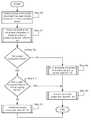
- FIG. 3Ashows a flowchart of a method in accordance with one or more embodiments of the invention.
- the method depicted in FIG. 3Amay be used to manage removable components in accordance with one or more embodiments of the invention.
- the method shown in FIG. 3Amay be performed by, for example, a component manager ( 120 , FIG. 1B ).
- the methodmay be performed by other components of the computing device ( 100 , FIG. 1B ) without departing from the invention.
- Step 300it is determined that a removable component has been directly connected to a first computing device.
- the determinationmay be made by receiving a notification from the removable component via an operable connection that the removable component has connected to the first computing device.
- the notificationmay be made when the removable component attempts to register with the first computing device.
- the determinationmay be made by, for example, detecting that the removable component has been directly connected to the first computing device.
- the detectionmay be made by the first computing device by monitoring a change in a load pull on the power supply.
- the determination in Step 300may be performed in response to the removable component being inserted in a chassis of the computing device. In one or more embodiments of the invention, the determination in Step 300 may be performed after the removable component is disposed in a chassis of the computing device.
- Step 302it is determined whether the removable component is bound to a second computing device.
- the determinationmay be made based on a binding stored in the removable component.
- the determination in Step 302may be performed in response to the removable component being inserted in a chassis of the computing device. In one or more embodiments of the invention, the determination in Step 302 may be performed while the removable component is disposed in a chassis of the computing device. In one or more embodiments of the invention, the determination in Step 302 may be performed while the removable component is not disposed in a chassis of the second computing device. In one or more embodiments of the invention, the determination in Step 302 may be performed after the removable component is removed from a chassis of the second computing device.
- the determinationmay be made via the method illustrated in FIG. 3B .
- Step 304if the removable component is bound to a second component as determined in Step 302 , the method proceeds to Step 310 . If the removable component is not bound to the second component as determined in Step 302 , the method proceeds to Step 306 .
- Step 306the removable component is bound to the first computing device.
- the removable componentmay be bound to the first computing device using an identifier of the first removable component.
- the removable componentis bound via the method illustrated in FIG. 3C .
- Step 308the removable component is activated.
- the removable componentis activated using the power supply by fully powering the removable component.
- the removable componentis activated via the method illustrated in FIG. 3D .
- the methodmay end following Step 308 .
- Step 304the method may proceed to Step 310 if the removable component is bound to a second computing device.
- Step 310it is determined whether the removable component is bound to the first computing device.
- the removable componentmay be determined to be bound to the first computing device by comparing a binding of the removable component to an identifier of the first computing match. If the binding matches the identifier of the first computing device, the removable component is determined as being bound to the first computing device.
- Step 308is discussed above. If the removable component is not bound to the first computing device, the method proceeds to Step 312 .
- Step 312the removable component is disabled.
- the removable componentmay be disabled by prevent a primary and/or secondary function of the removable component from being performed.
- the removable componentmay be disable via the method shown in FIG. 3E .
- the methodmay end following Step 312 .
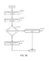
- FIG. 3Bshows a flowchart of a method in accordance with one or more embodiments of the invention.
- the method depicted in FIG. 3Bmay be used to determine whether a removable component is bound to a second computing device in accordance with one or more embodiments of the invention.
- the method shown in FIG. 3Bmay be performed by, for example, a component manager ( 120 , FIG. 1B ).
- the methodmay be performed by other components of the computing device ( 100 , FIG. 1B ) without departing from the invention.
- Step 320the removable component is partially activated.
- the removable componentmay be partially activated by partially powering the removable component.
- the removable componentmay be partially activated using a power supply of the computing device.
- Step 322a binding is obtained from the removable component.
- the bindingmay be obtained by reading a persistent storage of the removable component.
- the persistent storagemay be read while the removable component is partially powered.
- the bindingmay be obtained by receiving the binding from the removable component via an operable connection.
- the persistent storagemay be received while the removable component is partially powered.
- Step 324it is determined whether the binding exists.
- the bindingmay be determined as not existing by matching the binding to a predetermined byte sequence.
- the predetermined byte sequencemay indicate that any binding that matches the aforementioned predetermined byte sequence is not bound to any computing device.
- Step 326If the binding exists, the method proceeds to Step 326 . If the binding does not exist, the method proceeds to Step 328 .
- Step 326the removable component is determined to be bound to the second computing device.
- the methodmay end following Step 326 .
- Step 324the method may proceed to Step 328 if the binding does not exist.
- Step 328the removable component determined to not be bound to the second computing device.
- the removable componentis determined to not be bound to any computing device in Step 328 .
- the methodmay end following Step 328 .
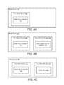
- FIG. 3Cshows a flowchart of a method in accordance with one or more embodiments of the invention.
- the method depicted in FIG. 3Cmay be used to bind a removable component to the first computing device in accordance with one or more embodiments of the invention.
- the method shown in FIG. 3Cmay be performed by, for example, a component manager ( 120 , FIG. 1B ).
- the methodmay be performed by other components of the computing device ( 100 , FIG. 1B ) without departing from the invention.
- Step 330an identifier of the first computing device is written to the persistent storage of the removable component as the binding of the removable component.
- the methodmay end following Step 330 .
- FIG. 3Dshows a flowchart of a method in accordance with one or more embodiments of the invention.
- the method depicted in FIG. 3Dmay be used to activate a removable component in accordance with one or more embodiments of the invention.
- the method shown in FIG. 3Dmay be performed by, for example, a component manager ( 120 , FIG. 1B ).
- the methodmay be performed by other components of the computing device ( 100 , FIG. 1B ) without departing from the invention.
- Step 340the removable component is fully powered.
- the removable componentmay be fully activated using a power supply controlled by the computing device.
- fully powering the removable componentmay activate both of a primary function and a secondary function of the removable component.
- the methodmay end following Step 340 .
- FIG. 3Eshows a flowchart of a method in accordance with one or more embodiments of the invention.
- the method depicted in FIG. 3Emay be used to disable a removable component in accordance with one or more embodiments of the invention.
- the method shown in FIG. 3Emay be performed by, for example, a component manager ( 120 , FIG. 1B ).
- the methodmay be performed by other components of the computing device ( 100 , FIG. 1B ) without departing from the invention.
- Step 350the removable component is depowered.
- the removable componentmay be depowered using a power supply controlled by the computing device.
- depowering the removable componentmay deactivate both of a primary function and a secondary function of the removable component.
- the methodmay end following Step 350 .
- FIGS. 4A-4Ean explanatory example is shown in FIGS. 4A-4E .
- the example shown in FIGS. 4A-4Eis included for explanatory purposes only and is not limiting.
- FIGS. 4A-4Ethe state of a blade server ( 400 ) is illustrated at different points in time. At the different points in time, various modules with various bindings are disposed in a chassis of the blade server ( 400 ) and the blade server ( 400 ) takes appropriate action based on the bindings.
- FIG. 4Ashows a diagram of the state of a blade server ( 400 ) at a first point in time.
- the blade serverincludes bays for housing removable components and implements the method illustrated in FIGS. 3A-3E .
- a first blade module ( 401 )is disposed in a bay of the blade server ( 400 ).
- the first blade module ( 401 )includes a binding, stored on a persistent storage of the first blade module ( 401 ), that includes the blade server identifier ( 402 ). Since the binding matches the blade server ( 400 ), the blade server ( 400 ) provides power to the first blade module ( 401 ) via a power supply (not shown) controlled by the blade server ( 400 ).
- FIG. 4Bshows a diagram of the state of the blade server ( 400 ) at a second point in time.
- a second blade module ( 405 )has been inserted into the chassis of the blade server ( 400 ).
- the second blade module ( 405 )has a binding that includes a second blade server identifier ( 406 ). Since the binding indicates that the second blade module ( 405 ) is bound to a second blade server (not shown), the blade server ( 400 ) disables the second blade module ( 405 ) by restricting power from being delivered to the second blade module ( 405 ) via the power supply (not shown) controlled by the blade server ( 400 ).
- FIG. 4Cshows a diagram of the state of the blade server ( 400 ) at a third point in time.
- a third blade module ( 410 )has been inserted into the chassis of the blade server ( 400 ).
- the third blade module ( 410 )has a binding that does not include an identifier of any computing device. Since the binding indicates that the third blade module ( 410 ) is not bound any computing devices, the blade server ( 400 ) initiates a binding procedure to bind the third blade module ( 410 ) to the blade server ( 400 ).
- FIG. 4Dshows a diagram of the state of the blade server ( 400 ) at a fourth point in time.
- the third blade module ( 410 )has been bound to the blade server ( 400 ) as indicated by the blade server identifier ( 402 ) being included in the binding of the third blade module ( 410 ). Since the binding now indicates that the third blade module ( 410 ) is bound to the blade server ( 400 ), the blade server ( 400 ) activates the third blade module ( 410 ) by fully powering the module using the power supply (not shown) controlled by the blade server ( 400 ).
- FIG. 4Eshows a diagram of the state of the blade server ( 400 ) at a fifth point in time.
- the third blade module ( 410 )has been replaced with a fourth blade module ( 415 ). Since the fourth blade module ( 415 ) has a binding that indicates that the fourth blade module ( 415 ) is bound to the blade server ( 400 ), the blade server ( 400 ) activates the fourth blade module ( 415 ) by fully powering the module using the power supply (not shown) controlled by the blade server ( 400 ).
- the exampleends after the state illustrated in FIG. 4E .
- One or more embodiments of the inventionmay be implemented using instructions executed by one or more processors in the data storage device. Further, such instructions may correspond to computer readable instructions that are stored on one or more non-transitory computer readable mediums.
- one or more embodiments of the inventionmay improve the management of removable components of computing devices. Due to the proliferation of ubiquitous compatibility between removable components and computing devices due to common standards for bus and interconnect architectures, removable components may be moved between computing devices. Embodiments of the invention may provide methods, systems, and devices for binding removable components to computing devices so that logical collections of removable components and computing devices may be formed. Computing devices in accordance with embodiments of the invention may take action to prevent removable computing devices from being used outside of their respective logical collection and thereby improve the manageability of removable components of computing devices by preventing the aforementioned removable components from being used outside of their respective logical collections. Embodiments of the invention may be used for other purposes and/or provide other functionality without departing from the invention.
- one or more embodiments of the inventionmay enable one or more of the following: i) binding of removable component to computing devices to form logical collections, ii) prevent removable components from being inadvertently moved between computing devices, and iii) improve the manageability of ubiquitously compatible removable components by prevent the aforementioned removable components from being activated outside of a computing device from which the removable components are bound.
Landscapes
- Engineering & Computer Science (AREA)
- Theoretical Computer Science (AREA)
- Software Systems (AREA)
- Physics & Mathematics (AREA)
- General Engineering & Computer Science (AREA)
- Computer Hardware Design (AREA)
- General Physics & Mathematics (AREA)
- Computer Security & Cryptography (AREA)
- Mathematical Physics (AREA)
- Computing Systems (AREA)
- Debugging And Monitoring (AREA)
Abstract
Description
Claims (19)
Priority Applications (3)
| Application Number | Priority Date | Filing Date | Title |
|---|---|---|---|
| US15/796,061US10496153B2 (en) | 2017-10-27 | 2017-10-27 | Method and system for binding chassis and components |
| EP18200661.9AEP3477468B1 (en) | 2017-10-27 | 2018-10-16 | Method and system for binding chassis and components |
| CN201811272966.5ACN109725688B (en) | 2017-10-27 | 2018-10-26 | Method and system for binding chassis and components |
Applications Claiming Priority (1)
| Application Number | Priority Date | Filing Date | Title |
|---|---|---|---|
| US15/796,061US10496153B2 (en) | 2017-10-27 | 2017-10-27 | Method and system for binding chassis and components |
Publications (2)
| Publication Number | Publication Date |
|---|---|
| US20190129497A1 US20190129497A1 (en) | 2019-05-02 |
| US10496153B2true US10496153B2 (en) | 2019-12-03 |
Family
ID=63878381
Family Applications (1)
| Application Number | Title | Priority Date | Filing Date |
|---|---|---|---|
| US15/796,061Active2038-03-14US10496153B2 (en) | 2017-10-27 | 2017-10-27 | Method and system for binding chassis and components |
Country Status (3)
| Country | Link |
|---|---|
| US (1) | US10496153B2 (en) |
| EP (1) | EP3477468B1 (en) |
| CN (1) | CN109725688B (en) |
Cited By (1)
| Publication number | Priority date | Publication date | Assignee | Title |
|---|---|---|---|---|
| US20220207186A1 (en)* | 2020-12-30 | 2022-06-30 | Dell Products, L.P. | Validating secure assembly and delivery of multiple information handling systems installed in a shared chassis |
Families Citing this family (1)
| Publication number | Priority date | Publication date | Assignee | Title |
|---|---|---|---|---|
| WO2024044843A1 (en)* | 2022-08-29 | 2024-03-07 | Ross Video Limited | Video processing equipment cover with integrated display |
Citations (53)
| Publication number | Priority date | Publication date | Assignee | Title |
|---|---|---|---|---|
| US6317028B1 (en)* | 1998-07-24 | 2001-11-13 | Electronic Security And Identification Llc | Electronic identification, control, and security system and method for consumer electronics and the like |
| US20010044782A1 (en)* | 1998-04-29 | 2001-11-22 | Microsoft Corporation | Hardware ID to prevent software piracy |
| US20040088145A1 (en) | 2002-11-06 | 2004-05-06 | Rosenthal Richard Edwin | Methods and apparatus for designing the racking and wiring configurations for pieces of hardware |
| US20040177168A1 (en)* | 2003-03-03 | 2004-09-09 | Microsoft Corporation | Verbose hardware identification for binding a software package to a computer system having tolerance for hardware changes |
| US20060179116A1 (en)* | 2003-10-10 | 2006-08-10 | Speeter Thomas H | Configuration management system and method of discovering configuration data |
| US20060178864A1 (en) | 2005-02-08 | 2006-08-10 | Madhavi Khanijo | Automated system and method for configuring a rack assembly |
| US7103874B2 (en) | 2003-10-23 | 2006-09-05 | Microsoft Corporation | Model-based management of computer systems and distributed applications |
| US7222127B1 (en) | 2003-11-14 | 2007-05-22 | Google Inc. | Large scale machine learning systems and methods |
| US20080228755A1 (en)* | 2007-03-14 | 2008-09-18 | Futoshi Haga | Policy creation support method, policy creation support system, and program therefor |
| US20090012805A1 (en)* | 2007-07-06 | 2009-01-08 | Microsoft Corporation | Portable Digital Rights for Multiple Devices |
| US7516362B2 (en) | 2004-03-19 | 2009-04-07 | Hewlett-Packard Development Company, L.P. | Method and apparatus for automating the root cause analysis of system failures |
| US20090165099A1 (en) | 2007-12-21 | 2009-06-25 | Avigdor Eldar | Provisioning active management technology (amt) in computer systems |
| US20090183010A1 (en)* | 2008-01-14 | 2009-07-16 | Microsoft Corporation | Cloud-Based Movable-Component Binding |
| US20090260071A1 (en)* | 2008-04-14 | 2009-10-15 | Microsoft Corporation | Smart module provisioning of local network devices |
| US20100024001A1 (en) | 2008-07-25 | 2010-01-28 | International Business Machines Corporation | Securing Blade Servers In A Data Center |
| US7831693B2 (en) | 2003-08-18 | 2010-11-09 | Oracle America, Inc. | Structured methodology and design patterns for web services |
| US7886031B1 (en)* | 2002-06-04 | 2011-02-08 | Symantec Operating Corporation | SAN configuration utility |
| US20110078428A1 (en)* | 2009-09-30 | 2011-03-31 | Memory Experts International Inc. | Portable desktop device and method of host computer system hardware recognition and configuration |
| US20110093703A1 (en) | 2009-10-16 | 2011-04-21 | Etchegoyen Craig S | Authentication of Computing and Communications Hardware |
| US7987353B2 (en) | 2008-01-09 | 2011-07-26 | International Business Machines Corporation | Remote BIOS for servers and blades |
| US20120041976A1 (en) | 2010-10-26 | 2012-02-16 | ParElastic Corporation | Mechanism for co-located data placement in a parallel elastic database management system |
| US8166552B2 (en) | 2008-09-12 | 2012-04-24 | Hytrust, Inc. | Adaptive configuration management system |
| US20120110142A1 (en) | 2010-10-29 | 2012-05-03 | Bank Of America Corporation | Configuration management utility |
| US20120150926A1 (en) | 2010-12-08 | 2012-06-14 | International Business Machines Corporation | Distributed free block map for a clustered redirect-on-write file system |
| US20120182151A1 (en) | 2011-01-19 | 2012-07-19 | Hon Hai Precision Industry Co., Ltd. | Server rack having payload weighing function |
| US20120331526A1 (en)* | 2011-06-22 | 2012-12-27 | TerraWi, Inc. | Multi-level, hash-based device integrity checks |
| US8386930B2 (en) | 2009-06-05 | 2013-02-26 | International Business Machines Corporation | Contextual data center management utilizing a virtual environment |
| US8401982B1 (en) | 2010-01-14 | 2013-03-19 | Symantec Corporation | Using sequencing and timing information of behavior events in machine learning to detect malware |
| US8583769B1 (en) | 2011-08-16 | 2013-11-12 | Edgecast Networks, Inc. | Configuration management repository for a distributed platform |
| US8639798B2 (en)* | 2008-01-21 | 2014-01-28 | International Business Machines Corporation | Managing configuration items |
| US20140069291A1 (en) | 2012-09-11 | 2014-03-13 | Shenzhen China Star Optoelectronics Technology Co., Ltd | Transmission system of LCD panel and automatic crane thereof |
| US8826077B2 (en) | 2007-12-28 | 2014-09-02 | International Business Machines Corporation | Defining a computer recovery process that matches the scope of outage including determining a root cause and performing escalated recovery operations |
| US20140281675A1 (en) | 2000-03-16 | 2014-09-18 | Sony Computer Entertainment America Llc | Flexible failover policies in high availability computing systems |
| US8868987B2 (en) | 2010-02-05 | 2014-10-21 | Tripwire, Inc. | Systems and methods for visual correlation of log events, configuration changes and conditions producing alerts in a virtual infrastructure |
| US8874892B1 (en) | 2011-05-26 | 2014-10-28 | Phoenix Technologies Ltd. | Assessing BIOS information prior to reversion |
| US8995439B2 (en) | 2010-05-13 | 2015-03-31 | Comcast Cable Communications, Llc | Control of multicast content distribution |
| US9122501B1 (en) | 2014-09-08 | 2015-09-01 | Quanta Computer Inc. | System and method for managing multiple bios default configurations |
| US20150256394A1 (en) | 2014-03-06 | 2015-09-10 | Dell Products, Lp | System and Method for Providing a Data Center Management Controller |
| US9201751B1 (en) | 2011-04-18 | 2015-12-01 | American Megatrends, Inc. | Data migration between multiple tiers in a storage system using policy based ILM for QOS |
| US20160048611A1 (en) | 2014-08-15 | 2016-02-18 | Vce Company, Llc | System, Method, Apparatus, and Computer Program Product for Generation of an Elevation Plan for a Computing System |
| US20160057009A1 (en) | 2014-08-21 | 2016-02-25 | Netapp, Inc. | Configuration of peered cluster storage environment organized as disaster recovery group |
| US9278481B2 (en) | 2010-10-26 | 2016-03-08 | Rinco Ultrasononics USA, INC. | Sonotrode and anvil energy director grids for narrow/complex ultrasonic welds of improved durability |
| US9355036B2 (en) | 2012-09-18 | 2016-05-31 | Netapp, Inc. | System and method for operating a system to cache a networked file system utilizing tiered storage and customizable eviction policies based on priority and tiers |
| US20160302323A1 (en) | 2015-04-09 | 2016-10-13 | Ortronics, Inc. | Equipment Cabinet and Associated Methods |
| US9542177B1 (en) | 2012-10-30 | 2017-01-10 | Amazon Technologies, Inc. | Peer configuration analysis and enforcement |
| US20170094003A1 (en) | 2015-09-30 | 2017-03-30 | Symantec Corporation | Preventing data corruption due to pre-existing split brain |
| US20170339005A1 (en) | 2015-02-10 | 2017-11-23 | Huawei Technologies Co., Ltd. | Method and Device for Processing Failure in at Least One Distributed Cluster, and System |
| US9864634B2 (en) | 2012-02-06 | 2018-01-09 | International Business Machines Corporation | Enhancing initial resource allocation management to provide robust reconfiguration |
| US20180034709A1 (en)* | 2015-01-08 | 2018-02-01 | Zte Corporation | Method and Device for Asset Information Management |
| US9898224B1 (en) | 2012-09-12 | 2018-02-20 | EMC IP Holding Company LLC | Automatic adjustment of capacity usage by data storage optimizer for data migration |
| US10057184B1 (en) | 2014-11-10 | 2018-08-21 | Amazon Technologies, Inc. | Resource configuration compliance service |
| US20180285009A1 (en)* | 2017-03-30 | 2018-10-04 | Intel Corporation | Dynamically composable computing system, a data center, and method for dynamically composing a computing system |
| US10097620B2 (en) | 2014-07-11 | 2018-10-09 | Vmware Inc. | Methods and apparatus to provision a workload in a virtual server rack deployment |
Family Cites Families (1)
| Publication number | Priority date | Publication date | Assignee | Title |
|---|---|---|---|---|
| US8887258B2 (en)* | 2011-08-09 | 2014-11-11 | Qualcomm Incorporated | Apparatus and method of binding a removable module to an access terminal |
- 2017
- 2017-10-27USUS15/796,061patent/US10496153B2/enactiveActive
- 2018
- 2018-10-16EPEP18200661.9Apatent/EP3477468B1/enactiveActive
- 2018-10-26CNCN201811272966.5Apatent/CN109725688B/enactiveActive
Patent Citations (53)
| Publication number | Priority date | Publication date | Assignee | Title |
|---|---|---|---|---|
| US20010044782A1 (en)* | 1998-04-29 | 2001-11-22 | Microsoft Corporation | Hardware ID to prevent software piracy |
| US6317028B1 (en)* | 1998-07-24 | 2001-11-13 | Electronic Security And Identification Llc | Electronic identification, control, and security system and method for consumer electronics and the like |
| US20140281675A1 (en) | 2000-03-16 | 2014-09-18 | Sony Computer Entertainment America Llc | Flexible failover policies in high availability computing systems |
| US7886031B1 (en)* | 2002-06-04 | 2011-02-08 | Symantec Operating Corporation | SAN configuration utility |
| US20040088145A1 (en) | 2002-11-06 | 2004-05-06 | Rosenthal Richard Edwin | Methods and apparatus for designing the racking and wiring configurations for pieces of hardware |
| US20040177168A1 (en)* | 2003-03-03 | 2004-09-09 | Microsoft Corporation | Verbose hardware identification for binding a software package to a computer system having tolerance for hardware changes |
| US7831693B2 (en) | 2003-08-18 | 2010-11-09 | Oracle America, Inc. | Structured methodology and design patterns for web services |
| US20060179116A1 (en)* | 2003-10-10 | 2006-08-10 | Speeter Thomas H | Configuration management system and method of discovering configuration data |
| US7103874B2 (en) | 2003-10-23 | 2006-09-05 | Microsoft Corporation | Model-based management of computer systems and distributed applications |
| US7222127B1 (en) | 2003-11-14 | 2007-05-22 | Google Inc. | Large scale machine learning systems and methods |
| US7516362B2 (en) | 2004-03-19 | 2009-04-07 | Hewlett-Packard Development Company, L.P. | Method and apparatus for automating the root cause analysis of system failures |
| US20060178864A1 (en) | 2005-02-08 | 2006-08-10 | Madhavi Khanijo | Automated system and method for configuring a rack assembly |
| US20080228755A1 (en)* | 2007-03-14 | 2008-09-18 | Futoshi Haga | Policy creation support method, policy creation support system, and program therefor |
| US20090012805A1 (en)* | 2007-07-06 | 2009-01-08 | Microsoft Corporation | Portable Digital Rights for Multiple Devices |
| US20090165099A1 (en) | 2007-12-21 | 2009-06-25 | Avigdor Eldar | Provisioning active management technology (amt) in computer systems |
| US8826077B2 (en) | 2007-12-28 | 2014-09-02 | International Business Machines Corporation | Defining a computer recovery process that matches the scope of outage including determining a root cause and performing escalated recovery operations |
| US7987353B2 (en) | 2008-01-09 | 2011-07-26 | International Business Machines Corporation | Remote BIOS for servers and blades |
| US20090183010A1 (en)* | 2008-01-14 | 2009-07-16 | Microsoft Corporation | Cloud-Based Movable-Component Binding |
| US8639798B2 (en)* | 2008-01-21 | 2014-01-28 | International Business Machines Corporation | Managing configuration items |
| US20090260071A1 (en)* | 2008-04-14 | 2009-10-15 | Microsoft Corporation | Smart module provisioning of local network devices |
| US20100024001A1 (en) | 2008-07-25 | 2010-01-28 | International Business Machines Corporation | Securing Blade Servers In A Data Center |
| US8166552B2 (en) | 2008-09-12 | 2012-04-24 | Hytrust, Inc. | Adaptive configuration management system |
| US8386930B2 (en) | 2009-06-05 | 2013-02-26 | International Business Machines Corporation | Contextual data center management utilizing a virtual environment |
| US20110078428A1 (en)* | 2009-09-30 | 2011-03-31 | Memory Experts International Inc. | Portable desktop device and method of host computer system hardware recognition and configuration |
| US20110093703A1 (en) | 2009-10-16 | 2011-04-21 | Etchegoyen Craig S | Authentication of Computing and Communications Hardware |
| US8401982B1 (en) | 2010-01-14 | 2013-03-19 | Symantec Corporation | Using sequencing and timing information of behavior events in machine learning to detect malware |
| US8868987B2 (en) | 2010-02-05 | 2014-10-21 | Tripwire, Inc. | Systems and methods for visual correlation of log events, configuration changes and conditions producing alerts in a virtual infrastructure |
| US8995439B2 (en) | 2010-05-13 | 2015-03-31 | Comcast Cable Communications, Llc | Control of multicast content distribution |
| US9278481B2 (en) | 2010-10-26 | 2016-03-08 | Rinco Ultrasononics USA, INC. | Sonotrode and anvil energy director grids for narrow/complex ultrasonic welds of improved durability |
| US20120041976A1 (en) | 2010-10-26 | 2012-02-16 | ParElastic Corporation | Mechanism for co-located data placement in a parallel elastic database management system |
| US20120110142A1 (en) | 2010-10-29 | 2012-05-03 | Bank Of America Corporation | Configuration management utility |
| US20120150926A1 (en) | 2010-12-08 | 2012-06-14 | International Business Machines Corporation | Distributed free block map for a clustered redirect-on-write file system |
| US20120182151A1 (en) | 2011-01-19 | 2012-07-19 | Hon Hai Precision Industry Co., Ltd. | Server rack having payload weighing function |
| US9201751B1 (en) | 2011-04-18 | 2015-12-01 | American Megatrends, Inc. | Data migration between multiple tiers in a storage system using policy based ILM for QOS |
| US8874892B1 (en) | 2011-05-26 | 2014-10-28 | Phoenix Technologies Ltd. | Assessing BIOS information prior to reversion |
| US20120331526A1 (en)* | 2011-06-22 | 2012-12-27 | TerraWi, Inc. | Multi-level, hash-based device integrity checks |
| US8583769B1 (en) | 2011-08-16 | 2013-11-12 | Edgecast Networks, Inc. | Configuration management repository for a distributed platform |
| US9864634B2 (en) | 2012-02-06 | 2018-01-09 | International Business Machines Corporation | Enhancing initial resource allocation management to provide robust reconfiguration |
| US20140069291A1 (en) | 2012-09-11 | 2014-03-13 | Shenzhen China Star Optoelectronics Technology Co., Ltd | Transmission system of LCD panel and automatic crane thereof |
| US9898224B1 (en) | 2012-09-12 | 2018-02-20 | EMC IP Holding Company LLC | Automatic adjustment of capacity usage by data storage optimizer for data migration |
| US9355036B2 (en) | 2012-09-18 | 2016-05-31 | Netapp, Inc. | System and method for operating a system to cache a networked file system utilizing tiered storage and customizable eviction policies based on priority and tiers |
| US9542177B1 (en) | 2012-10-30 | 2017-01-10 | Amazon Technologies, Inc. | Peer configuration analysis and enforcement |
| US20150256394A1 (en) | 2014-03-06 | 2015-09-10 | Dell Products, Lp | System and Method for Providing a Data Center Management Controller |
| US10097620B2 (en) | 2014-07-11 | 2018-10-09 | Vmware Inc. | Methods and apparatus to provision a workload in a virtual server rack deployment |
| US20160048611A1 (en) | 2014-08-15 | 2016-02-18 | Vce Company, Llc | System, Method, Apparatus, and Computer Program Product for Generation of an Elevation Plan for a Computing System |
| US20160057009A1 (en) | 2014-08-21 | 2016-02-25 | Netapp, Inc. | Configuration of peered cluster storage environment organized as disaster recovery group |
| US9122501B1 (en) | 2014-09-08 | 2015-09-01 | Quanta Computer Inc. | System and method for managing multiple bios default configurations |
| US10057184B1 (en) | 2014-11-10 | 2018-08-21 | Amazon Technologies, Inc. | Resource configuration compliance service |
| US20180034709A1 (en)* | 2015-01-08 | 2018-02-01 | Zte Corporation | Method and Device for Asset Information Management |
| US20170339005A1 (en) | 2015-02-10 | 2017-11-23 | Huawei Technologies Co., Ltd. | Method and Device for Processing Failure in at Least One Distributed Cluster, and System |
| US20160302323A1 (en) | 2015-04-09 | 2016-10-13 | Ortronics, Inc. | Equipment Cabinet and Associated Methods |
| US20170094003A1 (en) | 2015-09-30 | 2017-03-30 | Symantec Corporation | Preventing data corruption due to pre-existing split brain |
| US20180285009A1 (en)* | 2017-03-30 | 2018-10-04 | Intel Corporation | Dynamically composable computing system, a data center, and method for dynamically composing a computing system |
Non-Patent Citations (12)
| Title |
|---|
| "Dell DRAC-Wikipedia"; XP055602141; Mar. 23, 2018; https://en.wikipedia.org/w/index.php?title=Dell_DRAC&oldid=831957421 (8 pages). |
| "Dell EMC OpenManage Essentials Version 2.3: User's Guide"; XP055602720; Oct. 1, 2017; https://topics-cdn.dell.com/pdf/openmanage-essentials-v23 users-guide en-us.pdf (376 pages). |
| "Integrated Dell Remote Access Controller 8 (iDRAC8)", Version 2.05.05.05 User's Guide, Dell Inc., Dec. 2014 (348 pages). |
| "Dell DRAC—Wikipedia"; XP055602141; Mar. 23, 2018; https://en.wikipedia.org/w/index.php?title=Dell_DRAC&oldid=831957421 (8 pages). |
| Duncan Tweed; "Baseline configuration"; BMC Software, Inc.; Apr. 7, 2015; retrieved from https://bmc.com/. |
| Duncan Tweed; "BMC Atrium Discovery User Guide"; BMC Software, Inc.; Mar. 2014; retrieved from https://bmc.com/. |
| Extended European Search Report issued in corresponding European Application No. 18200661.9 dated Apr. 1, 2019. (9 pages). |
| Extended European Search Report issued in corresponding European Application No. 19151952.9, dated Jul. 1, 2019. |
| Extended European Search Report issued in corresponding European Application No. 19165337.7, dated Aug. 28, 2019 (11 pages). |
| Extended European Search Report issued in corresponding European Application No. 19165339.3, dated Aug. 6, 2019 (12 pages). |
| Iler, Doug, et al., "Introducing iDRAC8 with Lifecycle Controller for Dell 13th Generation PowerEdge Servers", A Dell Deployment and Configuration Guide, Dell Inc., Sep. 2014 (16 pages). |
| Masoom Parvez; "AutomaticGroup Node"; BMC Software, Inc.; 2014; retrieved from https://bmc.com/. |
Cited By (2)
| Publication number | Priority date | Publication date | Assignee | Title |
|---|---|---|---|---|
| US20220207186A1 (en)* | 2020-12-30 | 2022-06-30 | Dell Products, L.P. | Validating secure assembly and delivery of multiple information handling systems installed in a shared chassis |
| US11514193B2 (en)* | 2020-12-30 | 2022-11-29 | Dell Products, L.P. | Validating secure assembly and delivery of multiple information handling systems installed in a shared chassis |
Also Published As
| Publication number | Publication date |
|---|---|
| EP3477468B1 (en) | 2021-08-18 |
| CN109725688A (en) | 2019-05-07 |
| CN109725688B (en) | 2023-07-18 |
| US20190129497A1 (en) | 2019-05-02 |
| EP3477468A1 (en) | 2019-05-01 |
Similar Documents
| Publication | Publication Date | Title |
|---|---|---|
| US11983129B2 (en) | Self-configuring baseboard management controller (BMC) | |
| US20220365683A1 (en) | Method for using bmc as proxy nvmeof discovery controller to provide nvm subsystems to host | |
| CN109471770B (en) | System management method and device | |
| US10296328B2 (en) | Infrastructure configuration and inventory manager | |
| US9015268B2 (en) | Remote direct storage access | |
| US9507604B2 (en) | Boot method and boot system | |
| TWI595364B (en) | Automatic image recovery method and server system | |
| CN107632846B (en) | Firmware upgrade method and device, chassis management module | |
| CN105281937B (en) | Server, service management system, and service management method | |
| US20130254527A1 (en) | Bios firmware updating method and electronic device | |
| US8901960B2 (en) | FPGA mounted apparatus and FPGA configuration method | |
| CN103853678B (en) | Board managing device and use its plate card management system and control card | |
| KR101887632B1 (en) | Server rack system based on bmc | |
| US12265625B2 (en) | Physical port validation for information handling systems | |
| US20150365781A1 (en) | Server systems | |
| CN104679685A (en) | Access method of baseboard management controller | |
| CN106547645B (en) | Method for automatically restoring image file and server system | |
| US10496153B2 (en) | Method and system for binding chassis and components | |
| CN117687703B (en) | Server startup method, device, system, storage medium and electronic device | |
| CN103138941B (en) | The communication means of server rack system | |
| CN107844311A (en) | A kind of server firmware upgrade method and device | |
| US20140181496A1 (en) | Method, Apparatus and Processor for Reading Bios | |
| US20240231807A9 (en) | Bidirectional version compatibility control | |
| US12105856B2 (en) | Validation and registration for information handling systems | |
| US20190087175A1 (en) | Ssd firmware download dual boot |
Legal Events
| Date | Code | Title | Description |
|---|---|---|---|
| FEPP | Fee payment procedure | Free format text:ENTITY STATUS SET TO UNDISCOUNTED (ORIGINAL EVENT CODE: BIG.); ENTITY STATUS OF PATENT OWNER: LARGE ENTITY | |
| AS | Assignment | Owner name:CREDIT SUISSE AG, CAYMAN ISLANDS BRANCH, AS COLLAT Free format text:PATENT SECURITY AGREEMENT (CREDIT);ASSIGNORS:DELL PRODUCTS L.P.;EMC CORPORATION;EMC IP HOLDING COMPANY LLC;AND OTHERS;REEL/FRAME:044535/0001 Effective date:20171128 Owner name:THE BANK OF NEW YORK MELLON TRUST COMPANY, N.A., A Free format text:PATENT SECURITY AGREEMENT (NOTES);ASSIGNORS:DELL PRODUCTS L.P.;EMC CORPORATION;EMC IP HOLDING COMPANY LLC;AND OTHERS;REEL/FRAME:044535/0109 Effective date:20171128 Owner name:CREDIT SUISSE AG, CAYMAN ISLANDS BRANCH, AS COLLATERAL AGENT, NORTH CAROLINA Free format text:PATENT SECURITY AGREEMENT (CREDIT);ASSIGNORS:DELL PRODUCTS L.P.;EMC CORPORATION;EMC IP HOLDING COMPANY LLC;AND OTHERS;REEL/FRAME:044535/0001 Effective date:20171128 Owner name:THE BANK OF NEW YORK MELLON TRUST COMPANY, N.A., AS COLLATERAL AGENT, TEXAS Free format text:PATENT SECURITY AGREEMENT (NOTES);ASSIGNORS:DELL PRODUCTS L.P.;EMC CORPORATION;EMC IP HOLDING COMPANY LLC;AND OTHERS;REEL/FRAME:044535/0109 Effective date:20171128 | |
| STPP | Information on status: patent application and granting procedure in general | Free format text:DOCKETED NEW CASE - READY FOR EXAMINATION | |
| AS | Assignment | Owner name:EMC IP HOLDING COMPANY LLC, MASSACHUSETTS Free format text:ASSIGNMENT OF ASSIGNORS INTEREST;ASSIGNORS:ILYAS, MOHAMMED HASHEEM;DAS, AKSHITA;MISHRA, MONICA;AND OTHERS;REEL/FRAME:044454/0001 Effective date:20171030 | |
| AS | Assignment | Owner name:THE BANK OF NEW YORK MELLON TRUST COMPANY, N.A., T Free format text:SECURITY AGREEMENT;ASSIGNORS:CREDANT TECHNOLOGIES, INC.;DELL INTERNATIONAL L.L.C.;DELL MARKETING L.P.;AND OTHERS;REEL/FRAME:049452/0223 Effective date:20190320 Owner name:THE BANK OF NEW YORK MELLON TRUST COMPANY, N.A., TEXAS Free format text:SECURITY AGREEMENT;ASSIGNORS:CREDANT TECHNOLOGIES, INC.;DELL INTERNATIONAL L.L.C.;DELL MARKETING L.P.;AND OTHERS;REEL/FRAME:049452/0223 Effective date:20190320 | |
| STPP | Information on status: patent application and granting procedure in general | Free format text:NON FINAL ACTION MAILED | |
| STPP | Information on status: patent application and granting procedure in general | Free format text:RESPONSE TO NON-FINAL OFFICE ACTION ENTERED AND FORWARDED TO EXAMINER | |
| STPP | Information on status: patent application and granting procedure in general | Free format text:NOTICE OF ALLOWANCE MAILED -- APPLICATION RECEIVED IN OFFICE OF PUBLICATIONS | |
| STPP | Information on status: patent application and granting procedure in general | Free format text:PUBLICATIONS -- ISSUE FEE PAYMENT VERIFIED | |
| STCF | Information on status: patent grant | Free format text:PATENTED CASE | |
| AS | Assignment | Owner name:THE BANK OF NEW YORK MELLON TRUST COMPANY, N.A., TEXAS Free format text:SECURITY AGREEMENT;ASSIGNORS:CREDANT TECHNOLOGIES INC.;DELL INTERNATIONAL L.L.C.;DELL MARKETING L.P.;AND OTHERS;REEL/FRAME:053546/0001 Effective date:20200409 | |
| AS | Assignment | Owner name:WYSE TECHNOLOGY L.L.C., CALIFORNIA Free format text:RELEASE OF SECURITY INTEREST AT REEL 044535 FRAME 0001;ASSIGNOR:CREDIT SUISSE AG, CAYMAN ISLANDS BRANCH;REEL/FRAME:058298/0475 Effective date:20211101 Owner name:EMC IP HOLDING COMPANY LLC, TEXAS Free format text:RELEASE OF SECURITY INTEREST AT REEL 044535 FRAME 0001;ASSIGNOR:CREDIT SUISSE AG, CAYMAN ISLANDS BRANCH;REEL/FRAME:058298/0475 Effective date:20211101 Owner name:EMC CORPORATION, MASSACHUSETTS Free format text:RELEASE OF SECURITY INTEREST AT REEL 044535 FRAME 0001;ASSIGNOR:CREDIT SUISSE AG, CAYMAN ISLANDS BRANCH;REEL/FRAME:058298/0475 Effective date:20211101 Owner name:DELL PRODUCTS L.P., TEXAS Free format text:RELEASE OF SECURITY INTEREST AT REEL 044535 FRAME 0001;ASSIGNOR:CREDIT SUISSE AG, CAYMAN ISLANDS BRANCH;REEL/FRAME:058298/0475 Effective date:20211101 | |
| AS | Assignment | Owner name:DELL MARKETING CORPORATION (SUCCESSOR-IN-INTEREST TO WYSE TECHNOLOGY L.L.C.), TEXAS Free format text:RELEASE OF SECURITY INTEREST IN PATENTS PREVIOUSLY RECORDED AT REEL/FRAME (044535/0109);ASSIGNOR:THE BANK OF NEW YORK MELLON TRUST COMPANY, N.A., AS NOTES COLLATERAL AGENT;REEL/FRAME:060753/0414 Effective date:20220329 Owner name:EMC IP HOLDING COMPANY LLC, TEXAS Free format text:RELEASE OF SECURITY INTEREST IN PATENTS PREVIOUSLY RECORDED AT REEL/FRAME (044535/0109);ASSIGNOR:THE BANK OF NEW YORK MELLON TRUST COMPANY, N.A., AS NOTES COLLATERAL AGENT;REEL/FRAME:060753/0414 Effective date:20220329 Owner name:EMC CORPORATION, MASSACHUSETTS Free format text:RELEASE OF SECURITY INTEREST IN PATENTS PREVIOUSLY RECORDED AT REEL/FRAME (044535/0109);ASSIGNOR:THE BANK OF NEW YORK MELLON TRUST COMPANY, N.A., AS NOTES COLLATERAL AGENT;REEL/FRAME:060753/0414 Effective date:20220329 Owner name:DELL PRODUCTS L.P., TEXAS Free format text:RELEASE OF SECURITY INTEREST IN PATENTS PREVIOUSLY RECORDED AT REEL/FRAME (044535/0109);ASSIGNOR:THE BANK OF NEW YORK MELLON TRUST COMPANY, N.A., AS NOTES COLLATERAL AGENT;REEL/FRAME:060753/0414 Effective date:20220329 | |
| AS | Assignment | Owner name:DELL MARKETING L.P. (ON BEHALF OF ITSELF AND AS SUCCESSOR-IN-INTEREST TO CREDANT TECHNOLOGIES, INC.), TEXAS Free format text:RELEASE OF SECURITY INTEREST IN PATENTS PREVIOUSLY RECORDED AT REEL/FRAME (053546/0001);ASSIGNOR:THE BANK OF NEW YORK MELLON TRUST COMPANY, N.A., AS NOTES COLLATERAL AGENT;REEL/FRAME:071642/0001 Effective date:20220329 Owner name:DELL INTERNATIONAL L.L.C., TEXAS Free format text:RELEASE OF SECURITY INTEREST IN PATENTS PREVIOUSLY RECORDED AT REEL/FRAME (053546/0001);ASSIGNOR:THE BANK OF NEW YORK MELLON TRUST COMPANY, N.A., AS NOTES COLLATERAL AGENT;REEL/FRAME:071642/0001 Effective date:20220329 Owner name:DELL PRODUCTS L.P., TEXAS Free format text:RELEASE OF SECURITY INTEREST IN PATENTS PREVIOUSLY RECORDED AT REEL/FRAME (053546/0001);ASSIGNOR:THE BANK OF NEW YORK MELLON TRUST COMPANY, N.A., AS NOTES COLLATERAL AGENT;REEL/FRAME:071642/0001 Effective date:20220329 Owner name:DELL USA L.P., TEXAS Free format text:RELEASE OF SECURITY INTEREST IN PATENTS PREVIOUSLY RECORDED AT REEL/FRAME (053546/0001);ASSIGNOR:THE BANK OF NEW YORK MELLON TRUST COMPANY, N.A., AS NOTES COLLATERAL AGENT;REEL/FRAME:071642/0001 Effective date:20220329 Owner name:EMC CORPORATION, MASSACHUSETTS Free format text:RELEASE OF SECURITY INTEREST IN PATENTS PREVIOUSLY RECORDED AT REEL/FRAME (053546/0001);ASSIGNOR:THE BANK OF NEW YORK MELLON TRUST COMPANY, N.A., AS NOTES COLLATERAL AGENT;REEL/FRAME:071642/0001 Effective date:20220329 Owner name:DELL MARKETING CORPORATION (SUCCESSOR-IN-INTEREST TO FORCE10 NETWORKS, INC. AND WYSE TECHNOLOGY L.L.C.), TEXAS Free format text:RELEASE OF SECURITY INTEREST IN PATENTS PREVIOUSLY RECORDED AT REEL/FRAME (053546/0001);ASSIGNOR:THE BANK OF NEW YORK MELLON TRUST COMPANY, N.A., AS NOTES COLLATERAL AGENT;REEL/FRAME:071642/0001 Effective date:20220329 Owner name:EMC IP HOLDING COMPANY LLC, TEXAS Free format text:RELEASE OF SECURITY INTEREST IN PATENTS PREVIOUSLY RECORDED AT REEL/FRAME (053546/0001);ASSIGNOR:THE BANK OF NEW YORK MELLON TRUST COMPANY, N.A., AS NOTES COLLATERAL AGENT;REEL/FRAME:071642/0001 Effective date:20220329 | |
| MAFP | Maintenance fee payment | Free format text:PAYMENT OF MAINTENANCE FEE, 4TH YEAR, LARGE ENTITY (ORIGINAL EVENT CODE: M1551); ENTITY STATUS OF PATENT OWNER: LARGE ENTITY Year of fee payment:4 |