US10495825B2 - Architecture for a fiber optic network - Google Patents
Architecture for a fiber optic networkDownload PDFInfo
- Publication number
- US10495825B2 US10495825B2US15/161,914US201615161914AUS10495825B2US 10495825 B2US10495825 B2US 10495825B2US 201615161914 AUS201615161914 AUS 201615161914AUS 10495825 B2US10495825 B2US 10495825B2
- Authority
- US
- United States
- Prior art keywords
- fiber
- hardened
- connectors
- cable
- optical
- Prior art date
- Legal status (The legal status is an assumption and is not a legal conclusion. Google has not performed a legal analysis and makes no representation as to the accuracy of the status listed.)
- Active, expires
Links
Images


Classifications
- G—PHYSICS
- G02—OPTICS
- G02B—OPTICAL ELEMENTS, SYSTEMS OR APPARATUS
- G02B6/00—Light guides; Structural details of arrangements comprising light guides and other optical elements, e.g. couplings
- G02B6/44—Mechanical structures for providing tensile strength and external protection for fibres, e.g. optical transmission cables
- G02B6/4439—Auxiliary devices
- G02B6/4471—Terminating devices ; Cable clamps
- G02B6/44715—Fan-out devices
- G—PHYSICS
- G02—OPTICS
- G02B—OPTICAL ELEMENTS, SYSTEMS OR APPARATUS
- G02B6/00—Light guides; Structural details of arrangements comprising light guides and other optical elements, e.g. couplings
- G02B6/24—Coupling light guides
- G02B6/36—Mechanical coupling means
- G02B6/38—Mechanical coupling means having fibre to fibre mating means
- G02B6/3807—Dismountable connectors, i.e. comprising plugs
- G02B6/3873—Connectors using guide surfaces for aligning ferrule ends, e.g. tubes, sleeves, V-grooves, rods, pins, balls
- G02B6/3874—Connectors using guide surfaces for aligning ferrule ends, e.g. tubes, sleeves, V-grooves, rods, pins, balls using tubes, sleeves to align ferrules
- G02B6/3878—Connectors using guide surfaces for aligning ferrule ends, e.g. tubes, sleeves, V-grooves, rods, pins, balls using tubes, sleeves to align ferrules comprising a plurality of ferrules, branching and break-out means
- G02B6/3879—Linking of individual connector plugs to an overconnector, e.g. using clamps, clips, common housings comprising several individual connector plugs
- G—PHYSICS
- G02—OPTICS
- G02B—OPTICAL ELEMENTS, SYSTEMS OR APPARATUS
- G02B6/00—Light guides; Structural details of arrangements comprising light guides and other optical elements, e.g. couplings
- G02B6/24—Coupling light guides
- G02B6/36—Mechanical coupling means
- G02B6/38—Mechanical coupling means having fibre to fibre mating means
- G02B6/3807—Dismountable connectors, i.e. comprising plugs
- G02B6/3873—Connectors using guide surfaces for aligning ferrule ends, e.g. tubes, sleeves, V-grooves, rods, pins, balls
- G02B6/3885—Multicore or multichannel optical connectors, i.e. one single ferrule containing more than one fibre, e.g. ribbon type
- G—PHYSICS
- G02—OPTICS
- G02B—OPTICAL ELEMENTS, SYSTEMS OR APPARATUS
- G02B6/00—Light guides; Structural details of arrangements comprising light guides and other optical elements, e.g. couplings
- G02B6/24—Coupling light guides
- G02B6/36—Mechanical coupling means
- G02B6/38—Mechanical coupling means having fibre to fibre mating means
- G02B6/3807—Dismountable connectors, i.e. comprising plugs
- G02B6/3887—Anchoring optical cables to connector housings, e.g. strain relief features
- G—PHYSICS
- G02—OPTICS
- G02B—OPTICAL ELEMENTS, SYSTEMS OR APPARATUS
- G02B6/00—Light guides; Structural details of arrangements comprising light guides and other optical elements, e.g. couplings
- G02B6/24—Coupling light guides
- G02B6/36—Mechanical coupling means
- G02B6/38—Mechanical coupling means having fibre to fibre mating means
- G02B6/3807—Dismountable connectors, i.e. comprising plugs
- G02B6/389—Dismountable connectors, i.e. comprising plugs characterised by the method of fastening connecting plugs and sockets, e.g. screw- or nut-lock, snap-in, bayonet type
- G02B6/3893—Push-pull type, e.g. snap-in, push-on
- G—PHYSICS
- G02—OPTICS
- G02B—OPTICAL ELEMENTS, SYSTEMS OR APPARATUS
- G02B6/00—Light guides; Structural details of arrangements comprising light guides and other optical elements, e.g. couplings
- G02B6/24—Coupling light guides
- G02B6/36—Mechanical coupling means
- G02B6/38—Mechanical coupling means having fibre to fibre mating means
- G02B6/3807—Dismountable connectors, i.e. comprising plugs
- G02B6/389—Dismountable connectors, i.e. comprising plugs characterised by the method of fastening connecting plugs and sockets, e.g. screw- or nut-lock, snap-in, bayonet type
- G02B6/3894—Screw-lock type
- G—PHYSICS
- G02—OPTICS
- G02B—OPTICAL ELEMENTS, SYSTEMS OR APPARATUS
- G02B6/00—Light guides; Structural details of arrangements comprising light guides and other optical elements, e.g. couplings
- G02B6/44—Mechanical structures for providing tensile strength and external protection for fibres, e.g. optical transmission cables
- G02B6/4401—Optical cables
- G02B6/4429—Means specially adapted for strengthening or protecting the cables
- G02B6/443—Protective covering
- G—PHYSICS
- G02—OPTICS
- G02B—OPTICAL ELEMENTS, SYSTEMS OR APPARATUS
- G02B6/00—Light guides; Structural details of arrangements comprising light guides and other optical elements, e.g. couplings
- G02B6/44—Mechanical structures for providing tensile strength and external protection for fibres, e.g. optical transmission cables
- G02B6/4439—Auxiliary devices
- G02B6/4457—Bobbins; Reels
- G—PHYSICS
- G02—OPTICS
- G02B—OPTICAL ELEMENTS, SYSTEMS OR APPARATUS
- G02B6/00—Light guides; Structural details of arrangements comprising light guides and other optical elements, e.g. couplings
- G02B6/44—Mechanical structures for providing tensile strength and external protection for fibres, e.g. optical transmission cables
- G02B6/4439—Auxiliary devices
- G02B6/4471—Terminating devices ; Cable clamps
- G—PHYSICS
- G02—OPTICS
- G02B—OPTICAL ELEMENTS, SYSTEMS OR APPARATUS
- G02B6/00—Light guides; Structural details of arrangements comprising light guides and other optical elements, e.g. couplings
- G02B6/24—Coupling light guides
- G02B6/36—Mechanical coupling means
- G02B6/38—Mechanical coupling means having fibre to fibre mating means
- G02B6/3807—Dismountable connectors, i.e. comprising plugs
- G02B6/3887—Anchoring optical cables to connector housings, e.g. strain relief features
- G02B6/3888—Protection from over-extension or over-compression
- Y—GENERAL TAGGING OF NEW TECHNOLOGICAL DEVELOPMENTS; GENERAL TAGGING OF CROSS-SECTIONAL TECHNOLOGIES SPANNING OVER SEVERAL SECTIONS OF THE IPC; TECHNICAL SUBJECTS COVERED BY FORMER USPC CROSS-REFERENCE ART COLLECTIONS [XRACs] AND DIGESTS
- Y10—TECHNICAL SUBJECTS COVERED BY FORMER USPC
- Y10T—TECHNICAL SUBJECTS COVERED BY FORMER US CLASSIFICATION
- Y10T29/00—Metal working
- Y10T29/49—Method of mechanical manufacture
- Y10T29/49826—Assembling or joining
Definitions
- Passive optical networksare becoming prevalent in part because service providers want to deliver high bandwidth communication capabilities to customers. Passive optical networks are a desirable choice for delivering high-speed communication data because they may not employ active electronic devices, such as amplifiers and repeaters, between a central office and a subscriber termination. The absence of active electronic devices may decrease network complexity and/or cost and may increase network reliability.
- An example networkcan include a central office that connects a number of end subscribers (also called end users herein) in a network.
- FIG. 1is a schematic diagram of a network 10 including a central office 11 that connects a number of subscribers 15 in the network 10 .
- the central officecan additionally connect to one or more larger networks, such as the Internet (not shown) and a public switched telephone network (PSTN).
- PSTNpublic switched telephone network
- Some cables in the network 10can be branched out from main cable lines 12 and routed to fiber distribution and access terminals (e.g., fiber distribution hubs or pedestals).
- feeder cablescan branch from main cable lines 12 at branch points and be routed to FDHs 13 .
- Such branched cablesmight extend from the FDHs 13 to smaller fiber access terminals (e.g., optical network terminals or drop terminals) 14 directly adjacent the business or home to which service may be provided.
- the various lines of the networkcan be aerial or housed within underground conduits.
- Splitters used in FDHs 13can accept feeder cables having a number of fibers and may split signals carried on those incoming fibers into, for example, 216 to 432 individual signals that may be associated with a like number of end user locations 15 .
- an optical splitteris provided prepackaged in an optical splitter module housing and provided with splitter output pigtails that extend from the module.
- the splitter output pigtailsare typically connectorized with, for example, SC, LC, or LX.5 connectors.
- the optical splitter moduleprovides protective packaging for the optical splitter components in the housing and thus provides for easy handling for otherwise fragile splitter components. This modular approach allows optical splitter modules to be added incrementally to fiber distribution and access terminals as required.
- Certain aspects of the disclosurerelate to architectures for fiber optic networks that allow for rapid fiber deployment.
- Certain aspects of the disclosurerelate to architectures for fiber optic networks that allow for efficient system upgrades.
- inventive aspectscan relate to individual features and to combinations of features. It is to be understood that both the forgoing general description and the following detailed description are exemplary and explanatory only and are not restrictive of the broad inventive concepts upon which the embodiments disclosed herein are based.
- FIG. 1shows a prior art telecommunication network
- FIG. 2shows an example architecture for a fiber optic network in accordance with the principles of the present disclosure
- FIG. 3is a schematic view of an example fiber distribution hub that can be used in the architecture of FIG. 2 ;
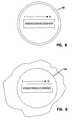
- FIG. 4illustrates an example hardened multi-fiber optical plug that can be used in the architecture of FIG. 2 ;
- FIG. 5illustrates a hardened multi-fiber optical jack that can be used in the architecture of FIG. 2 ;
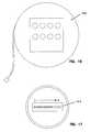
- FIG. 6illustrates a collector box that can be used in the architecture of FIG. 2 ;
- FIG. 7is another view of the collector box of FIG. 6 ;
- FIG. 8is a schematic view of an end of a twelve fiber version of a hardened multi-fiber optic connector used in the architecture of FIG. 2 ;
- FIG. 9is a schematic view of a port of the collector box of FIGS. 6 and 7 ;
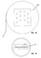
- FIGS. 10 and 11show an example four port multi-service terminal that can be used in the architecture of FIG. 2 ;
- FIG. 12is an end view of a hardened multi-fiber connector used with the multi-service terminal of FIGS. 10 and 11 ;
- FIG. 13illustrates an example port of the multi-service terminal of FIGS. 10 and 11 ;
- FIG. 14illustrates a six port multi-service terminal that can be used in the architecture of FIG. 2 ;
- FIG. 15is an end view of a multi-fiber optical connector of the multi-service terminal of FIG. 14 ;
- FIG. 16shows an eight port multi-service terminal that can be used in the architecture of FIG. 2 ;
- FIG. 17is an end view of a multi-fiber optical connector that can be used with the multi-service terminal of FIG. 16 ;
- FIG. 18shows a twelve port multi-service terminal that can be used with the architecture of FIG. 2 ;
- FIG. 19is an end view of a multi-fiber optical connector that can be used with the multi-service terminal of FIG. 18 ;
- FIG. 20schematically shows a hardened outside plant fan-out device that can be used with the architecture of FIG. 2 ;
- FIG. 21is a cross-sectional view taken along section line 21 - 21 of FIG. 20 ;
- FIG. 22is a cross-sectional view taken along section line 22 - 22 of FIG. 20 ;
- FIG. 23is a cross-sectional view taken along section line 23 - 23 of FIG. 20 ;
- FIG. 24is a cross-sectional view taken along section line 24 - 24 of FIG. 20 ;
- FIG. 25shows an alternative hardened outside plant fan-out device that can be used in the architecture of FIG. 2 ;
- FIG. 26is a cross-sectional view taken along section line 26 - 26 of FIG. 25 ;
- FIG. 27is a cross-sectional view taken along section line 27 - 27 of FIG. 25 ;
- FIG. 28shows a further hardened outside plant fan-out device that can be used in the architecture of FIG. 2 ;
- FIG. 29is s cross-sectional view taken along section line 29 - 29 of FIG. 28 ;
- FIG. 30is a cross-sectional view taken along section line 30 - 30 of FIG. 28 ;
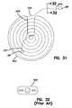
- FIG. 31illustrates an example rapid outdoor patch cord assembly that can be used in the architecture of FIG. 2 ;
- FIG. 32is a cross-sectional view taken along section line 32 - 32 of FIG. 31 ;
- FIG. 33illustrates a patching system in accordance with the principles of the present disclosure
- FIG. 34illustrates a capacity upgrade to the patching system of FIG. 33 ;
- FIG. 35illustrates a cable arrangement in accordance with the principles of the present disclosure.
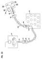
- FIG. 2shows example architecture 20 for a fiber optic network in accordance with the principles of the present disclosure.
- the architecture 20is used to distribute fiber optic service from a central office 22 to a plurality of subscriber/user locations 24 .
- various fiber optic cablesare routed underground to a plurality of hand holes 26 located in general proximity to the various locations of the subscriber locations 24 .
- the architecture 20can include a feeder cable 28 including one or more optical fibers routed from the central office 22 to a fiber distribution hub 30 .
- the fiber distribution hub 30can include one or more optical splitters for splitting signals input from the feeder cable 28 and directing the split signals to a plurality of output cables 32 .
- the output cables 32can extend from the fiber distribution hub 30 into a hand hole 26 A located beneath the fiber distribution hub 30 .
- Each of the output cables 32can be terminated with a hardened multi-fiber fiber optic connector 68 (e.g., a 12 fiber connector) located within the hand hole 26 A.
- the hardened multi-fiber fiber optic connectors 68can be connected to corresponding hardened multi-fiber fiber optic connectors 68 terminating a multi-fiber distribution cable 36 to provide optical couplings between the output cables 32 and the distribution cable 36 .
- the distribution cable 36is routed underground to a collector box 38 located at hand hole 26 F. To reach hand hole 26 F, the multi-fiber distribution cable 36 is routed through a series of intermediate hand holes 26 B- 26 E and through a series of underground conduits 40 (only some shown) that extend between the hand holes.
- the collector box 38is preferably positioned at an intermediate one of the hand holes 26 A- 26 K. From the collector box 38 , a multi-fiber optic cable can be routed to a multi-service terminal 42 within the hand hole 26 F. Additional cables can be routed in upstream and downstream directions from the hand hole 26 F through the underground conduits 40 to multi-service terminals 42 positioned within hand holes 26 B- 26 E and in hand holes 26 G- 26 K.
- the multi-service terminals 42provide connection locations for readily connecting fiber optic drop cables 46 to the remainder of the network.
- the drop cables 46can extend from the multi service terminals 42 to network interface devices provided at the subscriber locations 24
- Hardened outside plant fan-out devices 44can be used to facilitate directing optical signals to two or more separate multi-service terminals 42 without needing to utilize a separate port on the collection box 38 for each of the multi-service terminals 42 ,
- the distribution architecture 20is configured to facilitate rapid deployment of the network in the field.
- rapid spooling technologycan be incorporated into any of the various components (e.g., the fiber distribution hub 30 , the collector boxes 38 and the multi-service terminals 42 ) of the distribution architecture 20 .
- rapid spooling technologycan also be used in combination with patch cords routed between various components of the distribution architecture 20 .
- Such rapid spooling technologyallows fiber optic cables to be readily pulled through the underground conduits 40 from hand hole to hand hole.
- many of the system components/connectorsare preferably pre-terminated at the factory and thereby equipped with plug-and-play technology that can reduce or eliminate the need for optical splicing in the field.
- plug-and-play technologycan be used to readily interconnect the various components of the architecture 20 .
- Such plug-and-play technologyalso allows the architecture 20 to be readily upgraded after deployment with minimal or no need for field splicing.
- FIG. 3is a schematic representation of the fiber distribution hub 30 of FIG. 2 .
- the fiber distribution hubincludes an outer enclosure 50 (e.g., an environmentally sealed cabinet with one or more doors for accessing the interior of the cabinet) containing a splitter location 52 and a termination region 54 .
- the splitter location 52can include one or more splitter mounting positions for mounting optical splitter modules.
- the optical splitter modulescan include optical splitters used to split input signals from the optical fibers of the feeder cable 28 to a plurality of connectorized pigtails 56 . It will be appreciated that the splitters can provide any number of different split ratios (e.g., one to eight split ratio, one to sixteen split ratio, one to thirty two split ratio, etc.).
- the connectorized pigtails 56include optical connectors 58 (e.g., SC connectors) that plug into fiber optic adapters 60 (e.g., SC fiber optic adapters) provided at the termination region 54 .
- the fiber optic adapters 60assist in coupling the optical connectors 58 to corresponding optical connectors 62 (e.g., SC connectors) terminating the ends of output pigtails 64 .
- the output pigtails 64are routed to the output cables 32 that extend out of the enclosure 50 into the hand hole 26 A. Outer ends of the output cables 32 are terminated with the hardened multi-fiber optical connectors 68 .
- fiber distribution hub 30provides at least 288 terminations corresponding to 288 output fibers routed through the output cables 32 .
- the fiberscan be organized in groups of fibers corresponding to the number of fibers terminated at each of the hardened multi-fiber optical connectors 68 .
- the fiber optic adapters 60 at the termination region 54can be arranged in sets of 12 with each set of 12 corresponding to a given one of the hardened multi-fiber optical connectors 68 .
- 24 sets of 12 fiber optic adapterscan be provided at the termination region 54 , and 24 twelve fiber output cables 32 each having a twelve fiber hardened multi-fiber optical connector 68 can be routed out of the enclosure 50 .
- the hardened multi-fiber optical connectors 68are preferably adapted for outside environmental use.
- hardened multi-fiber optical connectors 68can include one or more environmental seals for preventing moisture intrusion into the connector 68 .
- the hardened multi-fiber optical connectors 68can include robust fasteners (e.g., threaded fasteners) capable of withstanding relatively large tensile loads. Further details relating to the fiber distribution hub 30 can be found at U.S. Provisional Patent Application Ser. No. 61/310,214 that is hereby incorporated by reference in its entirety.
- hardened multi-fiber optical connectors 68can be either hardened multi-fiber jacks or hardened multi-fiber plugs.
- FIG. 4shows an example of hardened multi-fiber optical plug 70
- FIG. 5shows a corresponding hardened multi-fiber optical jack 72 .
- the plug 70 and the jack 72are adapted to be mechanically and optically coupled together.
- the hardened multi-fiber optical plug 70includes a housing assembly 74 A supporting a multi-fiber ferrule 76 A supporting the ends of a plurality of optical fibers 78 A (e.g., 12 fibers).
- An externally threaded coupling nut 80 Ais mounted on the housing assembly 74 A.
- the hardened multi-fiber optical jack 72includes a housing assembly 74 B.
- a multi-fiber ferrule 76 Bis supported within the housing assembly 74 B.
- the multi-fiber ferrule 76 Bsupports a plurality of optical fibers 78 B.
- An internally threaded coupling nut 80 Bis mounted on the housing assembly 74 B.
- One or more environmental sealscan be provided between the housing assemblies 74 A, 74 B to prevent water intrusion into the optical plug 70 and the optical jack 72 when the components are coupled together. Further details about the hardened multi-fiber optical plug 70 and the hardened multi-fiber optical jack 72 can be found in U.S. Pat. No. 7,264,402 to Theuerkorn et al., the disclosure of which is hereby incorporated by reference herein in its entirety.
- FIG. 6schematically illustrates the collector box 38 of the distribution architecture 20 .
- the collector box 30includes a housing 100 that is preferably environmentally sealed.
- a plurality of ports 102are provided on the housing 100 .
- the ports 102are preferably configured to provide optical connections with hardened multi-fiber optical connectors 68 (e.g., hardened multi-fiber optic plug 70 or hardened multi-fiber optic jack 72 ).
- the ports 102can comprise hardened multi-fiber optical jacks 72 configured to receive hardened multi-fiber optical plugs 70 .
- the ports 102can include converters having exterior ends adapted to receive a hardened multi-fiber optical plug or hardened multi-fiber optical jack, and interior ends adapted to receive standard non-hardened multi-fiber optical connectors (e.g., MPO/MTP connectors).
- An example non-hardened multi-fiber optical connectoris disclosed at U.S. Pat. No. 5,214,730 to Nagasawa et al., that is hereby incorporated by reference herein in its entirety.
- An example converter that can be used at the ports 102is disclosed at U.S. Patent Application Publication No. US2008/0226235 A1, that is hereby incorporated by reference herein in its entirety.
- the ports 102provide connection locations whereby multi-fiber optical connectors located within the housing 100 can be optically connected to multi-fiber optical connectors located outside of the housing 100 .
- the multi-fiber optical connectors located within the housing 100can be non-hardened (e.g., standard MPO connectors) and the multi-fiber optical connectors received within the ports 102 from outside the housing 100 can be hardened (e.g., hardened multi-fiber optical plugs 70 or hardened multi-fiber optical jacks 72 ).
- hardened multi-fiber optical plugs 70 or hardened multi-fiber optical jacks 72can be mounted directly to the housing 100 at the ports 102 thereby providing connection locations whereby corresponding hardened multi-fiber optical plugs/hardened multi-fiber optical jacks can interface with the housing 100 .
- a spool 104can be mounted to the housing 100 .
- Multi-fiber optic cable 36can be coiled about the spool 104 .
- the multi-fiber optic cable 36includes 144 fibers and the housing 100 includes 12 ports with 12 of the optical fibers being routed to each of the 12 ports. In other embodiments, more or fewer ports can be provided.
- a 72 fiber optical cablecan be utilized and the housing 100 can include 6 active ports each accommodating 12 of the optical fibers of the fiber optic cable.
- the multi-fiber optical cable 36has a first end 37 that is routed from the spool 104 into the interior of the housing 100 .
- the optical fibers of the fiber optic cable 36are fanned out and directed in groups to each of the ports 102 .
- the fibers within the housing 100can be terminated with a standard MTP connector if interface converters are utilized at the ports 102 .
- the fibers within the housing 100can be terminated with hardened multi-fiber optical plugs or hardened multi-fiber optical jacks provided at the ports 102 .
- the multi-fiber optic cable 36can also include a second end 39 at which a plurality of hardened multi-fiber optical connectors 68 are terminated.
- the number of hardened multi-fiber optical connectors 68 provided at the second end of the multi-fiber optic cable 36equals the active number of ports provided at the housing 100 (e.g., Y connectors 68 and Y corresponding active ports are provided).
- the housing 100e.g., Y connectors 68 and Y corresponding active ports are provided.
- twelve ports each accommodating 12 fibersare provided at the housing 100 and twelve hardened multi-fiber optical connectors 68 each supporting 12 optical fibers are provided at the second end 39 of the cable.
- the cable 36includes a main body portion 41 and a plurality of broken-out portions 43 (i.e., fanned out portions or divided portions) to which the connectors 68 are terminated.
- a break-out/fan-out block 45is provided at the interface between the main body portion 41 and the broken-out portions 43 .
- Tensile strength members within jackets of the broken out portions 43can be secured to the connectors 68 and the break-out block 45 .
- Tensile strength members of the main body portion 41can be secured to the block 45 and the housing 100 .
- the hardened multi-fiber optical connectors 68 of the cable 36are adapted to optically connect with the hardened multi-fiber optical connectors terminating the output cables 32 of the fiber distribution hub 30 .
- the hardened multi-fiber fiber optic connectors 68 provided at the second end of the multi-fiber optical cable 36can be hardened multi-fiber optic plugs 70 or hardened multi-fiber optic jacks 72 .
- FIG. 8is a schematic view of an end of a twelve fiber version of one of the hardened multi-fiber optic connectors provided at the second end of the multi-fiber fiber optic cable 36 .
- FIG. 9is a schematic view of one of the ports 102 of the connector housing 100 . The port 102 is shown providing connection locations for twelve fibers.
- the collector box 38can initially be placed in the desired hand hole (e.g., hand hole 26 F). Once in the hand hole, the collector box 38 can be mounted on a spindle 106 within the hand hole. Thereafter, the multi-fiber optical cable 36 can be pulled from the hand hole 26 F through the underground conduits 40 to the hand hole 26 A where the hardened multi-fiber optic connectors 68 of the cable 36 are coupled to the hardened multi-fiber optical connectors 68 of the output cables 32 extending from the fiber distribution hub 30 . To route the multi-fiber fiber optic cable 36 through the conduit 40 , the second end 39 of the cable 36 can be connected to a pulling line used to pull the cable through the conduits 40 .
- the hardened multi-fiber optical connectors 68 of the cable 36can be arranged in a staggered configuration to facilitate passing the connectors through the conduit.
- the break-out cable portions extending from the break-out block 45have different lengths thereby allowing for staggering of the hardened multi-fiber optical connectors 68 .
- the spool 104 and the housing 100 with the ports 102spin in unison about the spindle 106 thereby allowing the multi-fiber fiber optic cable 36 to be paid off from the spool 104 .
- the multi-service terminals 42provide connection locations for connecting subscribers to the distribution architecture 20 .
- drop cables 46 having single optical fibersare routed between the multi-service terminals 42 and the subscriber locations 24 .
- the multi-service terminals 42include housing 202 that are preferably environmentally sealed.
- the housings 202include ports 204 at which the drop cables 46 can be connected to the distribution architecture 20 .
- spools 206can be mounted to the housings 202 . It will be appreciated that multi-service terminals can be provided with different number of active ports. For example, 4-port, 6-port, 8-port and 12-port multi-service terminals can be used.
- FIGS. 10 and 11show an example four port multi-service terminal 42 a .
- the terminal 42 aincludes a housing 202 that is preferably environmentally sealed.
- a plurality of ports 204configured to interface with single-fiber fiber optic connectors are provided on the housing 202 .
- a spool 206is also connected to the housing 202 .
- a multi-fiber optical cable 208is coiled about the spool 206 .
- a first end 207 of the multi-fiber optical cable 208extends from the spool 206 into the interior of the housing 202 .
- the optical fibers of the multi-fiber optical cable 208are fanned out and routed to the ports 204 .
- single fibersare routed to each of the ports 204 .
- the ports 204can include interior ends adapted for receiving non-hardened fiber optic connectors (e.g., SC connectors).
- the non-hardened fiber optic connectorscan be positioned within the housing 202 and can include ferrules supporting the ends of the fanned-out optical fibers within the housing 202 .
- Outer ends of the ports 204can be configured to receive hardened single fiber optical connectors 210 corresponding to the drop cables 46 . Examples of hardened single fiber optical connectors are disclosed at U.S. Pat. Nos. 6,648,520; 7,090,407; and 7,744,288 which are hereby incorporated by reference herein in their entireties.
- a second end 212 of the multi-fiber fiber optic cable 208is terminated by a hardened multi-fiber optical connector 68 (e.g., a hardened multi-fiber optical plug 70 or a hardened multi-fiber optical jack 72 ).
- FIG. 12shows an end view of the hardened multi-fiber optical connector 68 .
- the hardened multi-fiber optical connector 68includes a ferrule 214 defining twelve fiber positions (e.g., holes for receiving and supporting fibers therein). The fiber positions are numbered consecutively one through twelve. In the case of a 4-port multi-service terminal, positions 1-4 of the ferrule 214 will receive and support active fibers routed to corresponding ports 1-4 of the multi-service terminal.
- positions 1-6 of the ferrule 214will receive active fibers corresponding to the ports 1-6 of the terminal.
- positions 1-8 of the ferrule 214will receive fibers corresponding to ports 1-8 of the terminal.
- positions 1-8 of the ferrule 214will receive active fibers corresponding to the twelve ports of the terminal.
- the terminalis positioned within the hand hole in which it is desired to locate the terminal.
- the second end 212 of the cable 208is then pulled through the conduit 40 to a desired connection location where the hardened multi-fiber optical connector 68 can be connected to the distribution architecture 20 .
- a spindle structurecan be utilized to allow the spool 200 , the housing 202 and the ports 204 to spin in unison about a common axis as the multi-fiber fiber optic cable 208 is paid off from the spool 206 .
- the second end 212 of the multi-fiber optical cable 208can be pulled back all the way to the collector box 38 , or it can be pulled to an intermediate location between the multi-service terminal location and the collector box 38 .
- the hardened multi-fiber fiber optic connector 68can be plugged into a port 102 of the collector box 38 to provide optical connections therewith. After a sufficient length of the cable 208 has been paid off from the spool 206 , the hardened single fiber connectors of the drop cables 46 can be plugged into the ports 204 of the multi-service terminal. In this way, the subscriber locations are connected to the overall network.
- the hardened outside plant fan-out devices 44can be installed at locations between the multi-service terminals 42 and the collector boxes 38 of the distribution architecture 20 .
- FIG. 20shows a hardened outside plant fan-out device 44 A having a 3-way fan-out configuration.
- the fan-out device 44 Aincludes a 12-fiber cable 300 terminated at one end by a hardened multi-fiber optic connector 68 .
- the hardened multi-fiber optical connector 68includes a ferrule 302 supporting all twelve fibers of the cable 300 .
- the device 44 Aalso includes a fan-out block 304 in which the 12 fibers of the cable 300 are fanned out into three groups of four fibers that form fanned-out cable portions 306 .
- both the main cable 300 and the fanned-out cable portions 306can include tensile reinforcing structures 305 and outer jackets 307 .
- the tensile reinforcing structurescan be anchored to the fan-out block 304 and to the connectors 68 .
- the fanned-out cable portions 306are terminated by multi-fiber fiber optic connectors 68 .
- the fibers of the fanned out portionsoccupy positions 1-4 of the ferrules 302 of the multi-fiber fiber optic connectors 68 . Positions 5-12 of the hardened multi-fiber fiber optic connectors are not utilized for active fibers.
- the fan-out device 44 Ais adapted for distributing signals from the collector box 38 to three separate 4-port multi-service terminals.
- FIG. 25shows an alternative hardened outside plant fan-out device 44 B having the same configuration as the fan-out device 44 A except the 12 fibers are fanned out into two fanned-out cable portions each including six of the fibers (see FIG. 26 ).
- the fanned-out cable portionsare terminated by hardened multi-fiber fiber optic connectors 68 .
- the fibersoccupy positions 1-6 of the ferrule of the hardened multi-fiber fiber optic connectors 68 .
- the fan-out device 44 Bis adapted for distributing signals from the collector box 38 to two separate 6-port multi-service terminals.
- FIG. 28shows a further hardened outside plant fan-out device 44 C in accordance with the principles of the present disclosure.
- the fan-out device 44 Chas the same construction as the fan-out device 44 B except the fibers are not fanned out uniformly between the two fanned out cable portions. Instead, one of the fanned cable portions includes 8 fibers (see FIG. 29 ) while the other includes 4 fibers (similar to FIG. 22 ).
- the fanned out cable portion with 4 fibersis terminated by hardened multi-fiber fiber optic connector 68 and the fibers occupy positions 1-4 (as shown at FIG. 24 ) of the connector 68 .
- This hardened multi-fiber fiber optic connectoris adapted to interface with a 4-port multi-service terminal.
- the other fanned out cable portionis terminated by hardened multi-fiber optical connector 68 and the 8 fibers of the fanned out cable portion occupy positions 1-8 of the ferrule of the connector (see FIG. 30 ).
- This connectoris adapted to interface with an 8-port multi-service terminal.
- hardened outdoor patch cordscan be used within the distribution architecture to facilitate making upgrades.
- rapid patch cordscan be used in place of the spools on the multi-service terminals.
- the multi-fiber optical cables 208 exiting the multi-service terminalsconstitute relatively short tethers that are connectorized by a hardened multi-fiber fiber optic connector 68 . Due to the short length of the tether, it need not be coiled around a spool.
- a rapid patch cordcan be used to provide an optical connection between the tether and another structure.
- the rapid patch cordcan be used to connect the tether directly to the collection box 38 or it can be used to connect the tether to an intermediate hardened outside plant fan-out device 44 positioned between the collection box 38 and the multi-service terminal.
- rapid outside patch cablescan also be used to provide connections between the collection box 38 and one of the hardened outside plant fan-out devices 44 .
- FIGS. 31 and 32show an example rapid outdoor patch cord assembly including a multi-fiber cable 400 (e.g., a 12-fiber multi-fiber cable) coiled around a spool 402 .
- Hardened multi-fiber fiber optic connectors 68are mounted at opposite ends of the cable 400 .
- each of the hardened multi-fiber fiber optic connectors 68includes a ferrule having 12 positions in which end portions of the optical fibers of the cable 400 are secured.
- the cable 400 as well as the cables used to for the main body and fanned-out portions of the outside plant fan-out devicecan have a construction of the type described in U.S. patent application Ser. No. 12/607,748 which is hereby incorporated by reference herein in its entirety.
- the hardened multi-fiber fiber optic connector 68 positioned at a first end 407 of the cable 400can be secured to a flange of the spool 402 .
- the cable 400is spooled around a drum 406 of the spool.
- a slot 408 in the flange of the spoolallows the first end of the cable to be routed to an outside of the flange where the connector 68 is secured.
- a second end 409 of the cable 400is located at the outside diameter defined by the cable wrapped about the spool.
- the spool 400is mounted adjacent to a desired connection location (e.g., in a hand hole adjacent to n multi-service terminal, a collector box or a hardened outside plant fan-out device).
- the spool 402can be mounted on a spindle or another structure for allowing the spool to spin.
- the second end 409 of the cable 400is pulled causing the spool 402 to spin and cable to be paid off from the spool 402 .
- the second end 409is pulled through the underground conduits 40 and any intermediate hand holes to a second desired mounting location.
- any remaining cable on the spoolcan be cable tied and removed from the spool 402 thereby allowing the spool itself to be disposed of.
- the connectorized ends of the patch cablecan then be plugged into the desired connection locations to provide an optical patch there between.
- FIG. 33shows a system in which a twelve-fiber patch cord is routed through an underground conduit from collector box 38 to a 4-port multi-service terminal 42 A.
- the patch cordhas twelve fibers and hardened multi-fiber fiber optic connectors 68 supporting the twelve fibers at each end of the cable.
- One of the hardened multi-fiber optical connectorsis plugged into one of the ports 102 of the collector box 38 while the other hardened multi-fiber fiber optic connector 68 of the patch cable is plugged into a corresponding hardened multi-fiber optical connector 68 mounted at the end of a short tether 67 of the multi-service terminal 44 A.
- fibers 1-4 at a termination region of the fiber distribution hub 30correspond to positions 1-4 of the various hardened multi-fiber optical connectors 68 used on the output cable 32 from the fiber distribution hub, the distribution cable 36 routed to the collector box 38 , and the connectors 68 provided at the ends of the patch cord.
- Positions 1-4 of the ferrules on the termination panelcorrespond to ports 1-4 of the four port multi-service terminal 444 A.
- Fibers 5-12are currently unused and are available for ready upgrade in the event it is necessary to increase service capacity in region adjacent the multi-service terminal 44 A.
- the tether 67 of the terminal 42 Acan be disconnected from the patch cord by disconnecting the mated hardened multi-fiber fiber optic connectors 68 .
- a larger capacity multi-service terminale.g., a twelve-port terminal
- a larger capacity multi-service terminalcan be plugged into the patch cord to provide increased capacity.
- ports 1-4see FIG. 34
- positions 1-4 at the termination panelstill correspond to the same subscribers.
- fibers 5-12are now active and are available for additional subscribers.
- FIG. 35shows a cable arrangement 500 that can be used to replace the collector box 38 .
- Cable arrangement 500is depicted as including a 144-fiber patch cable, although other numbers of fibers could be used as well (e.g., 74 fibers, 288 fibers, etc.).
- the fibers within the cableare grouped into twelve groups of twelve. Each group of fibers is terminated by a multi-fiber fiber optic connector 68 at a first end 501 of the cable. Similarly, each of the groups of twelve fibers are terminated by a separate multi-fiber optical connector 65 at a second end 503 cable.
- the cablehas cable break out regions adjacent each of the ends. At the cable break out regions, individual broken out cable portions 507 are broken out from a main region 509 of the cable.
- Each of the individual broken out cable portions 507are terminated with a separate hardened multi-fiber fiber optic connector 65 .
- the broken out cable portions 507 on one end of the cablehave different lengths such that the multi-fiber optic connectors 68 are staggered relative to one another to facilitate pulling the connectors 68 through underground conduit.
- the multi-fiber fiber optic connectors 68are staggered relative to one another at both ends of the cable.
Landscapes
- Physics & Mathematics (AREA)
- General Physics & Mathematics (AREA)
- Optics & Photonics (AREA)
- Light Guides In General And Applications Therefor (AREA)
- Mechanical Coupling Of Light Guides (AREA)
Abstract
Description
Claims (16)
Priority Applications (2)
| Application Number | Priority Date | Filing Date | Title |
|---|---|---|---|
| US15/161,914US10495825B2 (en) | 2010-08-02 | 2016-05-23 | Architecture for a fiber optic network |
| US16/694,240US10830965B2 (en) | 2010-08-02 | 2019-11-25 | Architecture for a fiber optic network |
Applications Claiming Priority (4)
| Application Number | Priority Date | Filing Date | Title |
|---|---|---|---|
| US37007310P | 2010-08-02 | 2010-08-02 | |
| US13/196,623US8961035B2 (en) | 2010-08-02 | 2011-08-02 | Architecture for a fiber optic network |
| US14/574,672US9348097B2 (en) | 2010-08-02 | 2014-12-18 | Architecture for a fiber optic network |
| US15/161,914US10495825B2 (en) | 2010-08-02 | 2016-05-23 | Architecture for a fiber optic network |
Related Parent Applications (1)
| Application Number | Title | Priority Date | Filing Date |
|---|---|---|---|
| US14/574,672ContinuationUS9348097B2 (en) | 2010-08-02 | 2014-12-18 | Architecture for a fiber optic network |
Related Child Applications (1)
| Application Number | Title | Priority Date | Filing Date |
|---|---|---|---|
| US16/694,240ContinuationUS10830965B2 (en) | 2010-08-02 | 2019-11-25 | Architecture for a fiber optic network |
Publications (2)
| Publication Number | Publication Date |
|---|---|
| US20160341911A1 US20160341911A1 (en) | 2016-11-24 |
| US10495825B2true US10495825B2 (en) | 2019-12-03 |
Family
ID=45526807
Family Applications (4)
| Application Number | Title | Priority Date | Filing Date |
|---|---|---|---|
| US13/196,623Active2033-03-05US8961035B2 (en) | 2010-08-02 | 2011-08-02 | Architecture for a fiber optic network |
| US14/574,672ActiveUS9348097B2 (en) | 2010-08-02 | 2014-12-18 | Architecture for a fiber optic network |
| US15/161,914Active2031-10-13US10495825B2 (en) | 2010-08-02 | 2016-05-23 | Architecture for a fiber optic network |
| US16/694,240ActiveUS10830965B2 (en) | 2010-08-02 | 2019-11-25 | Architecture for a fiber optic network |
Family Applications Before (2)
| Application Number | Title | Priority Date | Filing Date |
|---|---|---|---|
| US13/196,623Active2033-03-05US8961035B2 (en) | 2010-08-02 | 2011-08-02 | Architecture for a fiber optic network |
| US14/574,672ActiveUS9348097B2 (en) | 2010-08-02 | 2014-12-18 | Architecture for a fiber optic network |
Family Applications After (1)
| Application Number | Title | Priority Date | Filing Date |
|---|---|---|---|
| US16/694,240ActiveUS10830965B2 (en) | 2010-08-02 | 2019-11-25 | Architecture for a fiber optic network |
Country Status (1)
| Country | Link |
|---|---|
| US (4) | US8961035B2 (en) |
Cited By (1)
| Publication number | Priority date | Publication date | Assignee | Title |
|---|---|---|---|---|
| US10830965B2 (en) | 2010-08-02 | 2020-11-10 | Commscope Technologies Llc | Architecture for a fiber optic network |
Families Citing this family (30)
| Publication number | Priority date | Publication date | Assignee | Title |
|---|---|---|---|---|
| US9261654B2 (en)* | 2009-10-13 | 2016-02-16 | Leviton Manufacturing Co., Inc. | Fiber optic adapter plates with integrated fiber optic adapters |
| US20120189259A1 (en)* | 2010-12-15 | 2012-07-26 | Leviton Manufacturing Co., Inc. | Pre-terminated fiber devices, systems, and methods |
| US20130216187A1 (en) | 2011-08-17 | 2013-08-22 | Douglas Ferris Dowling | Distributed passive optical networks |
| US9348096B2 (en)* | 2012-03-30 | 2016-05-24 | Commscope Technologies Llc | Passive distribution system using fiber indexing |
| CN104823090B (en) | 2012-11-30 | 2017-04-05 | 泰科电子公司 | Fiber optic connectors with field-installable outer connector housings |
| ES1141660Y (en) | 2012-12-19 | 2015-10-14 | Tyco Electronics Raychem Bvba | Distribution device with incrementally added dividers |
| US9316803B2 (en) | 2013-03-15 | 2016-04-19 | Leviton Manufacturing Co., Inc. | Efficient fiber usage within pre-terminated fiber devices |
| BR112015029297B1 (en)* | 2013-05-23 | 2022-11-29 | Adc Telecommunications, Inc | FIBER OPTICAL NETWORK ARCHITECTURE |
| CN104849816B (en)* | 2014-02-14 | 2017-01-11 | 泰科电子(上海)有限公司 | Optical fiber connector and assembly method therefor |
| CN104849815B (en) | 2014-02-14 | 2017-01-18 | 泰科电子(上海)有限公司 | Optical fiber connector and assembly method therefor |
| US9529172B2 (en)* | 2014-05-12 | 2016-12-27 | Lenovo Enterprise Solutions (Singapore) Pte. Ltd. | Breakout cable |
| AU2015276109B2 (en) | 2014-06-17 | 2020-11-19 | Adc Czech Republic, S.R.O. | Cable distribution system |
| CN105445862B (en) | 2014-07-09 | 2018-01-19 | 泰科电子(上海)有限公司 | The joints of optical fibre and its on-site assembly method |
| MX2017004130A (en) | 2014-10-06 | 2017-10-31 | Adc Telecommunications Inc | Facilitating installation of fiber optic networks. |
| US9874713B2 (en)* | 2015-01-30 | 2018-01-23 | Commscope Technologies Llc | Indexing terminals having a port arrangement environmentally sealed by a cover |
| US10560211B2 (en) | 2015-02-26 | 2020-02-11 | Commscope Technologies Llc | Cable arrangement with wavelength division multiplexer |
| EP3822676A1 (en)* | 2015-04-02 | 2021-05-19 | CommScope Technologies LLC | Fiber optic network architecture using high fiber-count fiber optic connectors |
| US10620385B2 (en) | 2015-11-30 | 2020-04-14 | Commscope Technologies Llc | Fiber optic connector and assembly thereof |
| US10606009B2 (en)* | 2015-12-01 | 2020-03-31 | CommScope Connectivity Belgium BVBA | Cable distribution system with fan out devices |
| US10641970B2 (en) | 2015-12-16 | 2020-05-05 | Commscope Technologies Llc | Field installed fiber optic connector |
| EP3408701B1 (en) | 2016-01-28 | 2023-04-26 | CommScope Connectivity Belgium BVBA | Modular telecommunications enclosure |
| MX2019001845A (en) | 2016-08-15 | 2019-05-09 | Commscope Technologies Llc | Indexing architecture including a fan-out arrangement. |
| US10690875B2 (en) | 2016-09-06 | 2020-06-23 | CommScope Connectivity Belgium BVBA | Indexing architecture including an optical fiber cable fan-out arrangement |
| EP3542198A1 (en)* | 2016-11-15 | 2019-09-25 | CommScope Connectivity Belgium BVBA | Optical and power network for modular equipment |
| US11002935B2 (en) | 2017-08-18 | 2021-05-11 | Commscope Technologies Llc | MST expansion closures; and methods |
| CN107612623A (en)* | 2017-09-05 | 2018-01-19 | 深圳市微风通讯技术有限公司 | A kind of multi-service expanding communication equipment |
| CN107632357B (en)* | 2017-10-19 | 2019-08-02 | 东莞中子科学中心 | Multimode optical fiber signal fan-out mechanism |
| EP3830622A4 (en)* | 2018-08-01 | 2022-05-04 | CommScope Technologies LLC | OUTPUT BRANCH DISTRIBUTION BOX WITH ISOLATED FIBER CHAMBER |
| US20220196958A1 (en)* | 2019-04-15 | 2022-06-23 | Commscope Technologies Llc | Cable arrangement within a data center |
| DE102019133706A1 (en)* | 2019-12-10 | 2021-06-10 | Hauff-Technik Gmbh & Co. Kg | Use to connect a data user or data distribution point |
Citations (74)
| Publication number | Priority date | Publication date | Assignee | Title |
|---|---|---|---|---|
| US3260794A (en) | 1964-04-23 | 1966-07-12 | Kohler & Besser Electronics In | Protective cover for cable splice |
| JPS60169813A (en) | 1984-02-15 | 1985-09-03 | Sumitomo Electric Ind Ltd | Optical branching terminal |
| EP0189609B1 (en) | 1984-12-05 | 1990-05-23 | Koninklijke Philips Electronics N.V. | Optical connector device |
| US5125060A (en) | 1991-04-05 | 1992-06-23 | Alcatel Na Cable Systems, Inc. | Fiber optic cable having spliceless fiber branch and method of making |
| US5210812A (en) | 1991-04-05 | 1993-05-11 | Alcatel Na Cable Systems, Inc. | Optical fiber cable having spliced fiber branch and method of making the same |
| US5242315A (en) | 1992-05-21 | 1993-09-07 | Puritan-Bennett Corporation | Electrical-optical hybrid connector plug |
| US5471555A (en) | 1994-11-21 | 1995-11-28 | Sumitomo Electric Lightwave Corp. | Fiber optic ribbon break-out device with enhanced strain relief |
| EP0880212A2 (en) | 1997-05-19 | 1998-11-25 | N.V. Raychem S.A. | Splice closure |
| US5966489A (en) | 1997-06-30 | 1999-10-12 | Siecor Corporation | Fiber optic ribbon interconnect cable |
| US5997186A (en) | 1998-05-13 | 1999-12-07 | Huynh; Van L. | Hybrid cable splice closure and related methods |
| USRE36529E (en) | 1992-03-06 | 2000-01-25 | The United States Of America As Represented By The Department Of Health And Human Services | Spectroscopic imaging device employing imaging quality spectral filters |
| USRE36592E (en) | 1994-07-01 | 2000-02-29 | Siecor Corporation | Optical receiver stub fitting |
| US6104855A (en) | 1997-09-30 | 2000-08-15 | Daewoo Telecom Ltd. | Terminal assembly for a multiple fiber optic cable |
| DE10008613A1 (en) | 2000-02-24 | 2001-09-06 | Dataline Kabel Gmbh | Reducer for joining a multi-cored cable, such as optical waveguide, to a flexible protective envelope or sheath, has fixture device joined to first end of tubular basic body for fixing protective sheath to basic body |
| US6364539B1 (en) | 1999-03-04 | 2002-04-02 | Avaya Technology Corp. | Stackable multi-fiber ferrules having improved interconnection density |
| US6438299B1 (en) | 1997-09-30 | 2002-08-20 | The United States Of America As Represented By The Secretary Of The Navy | Assembly and method for furcating optical fibers |
| US20030210861A1 (en)* | 2002-05-13 | 2003-11-13 | Creo Il. Ltd. | Individually addressable laser diode arrays based imaging systems with increased redundancy |
| US6796821B2 (en) | 2002-06-06 | 2004-09-28 | Ocean Design, Inc. | Field installable cable termination assembly |
| US20050259928A1 (en) | 2004-05-24 | 2005-11-24 | Elkins Robert B Ii | Distribution cable assembly having overmolded mid-span access location |
| US20060093277A1 (en) | 2004-10-29 | 2006-05-04 | Mulligan Paul M | Combination optical fiber and electrical connecter |
| US7054536B2 (en) | 2004-05-12 | 2006-05-30 | Molex Incorporated | Breakout assembly for flexible circuitry |
| US20060127026A1 (en) | 2004-12-10 | 2006-06-15 | Beck Ronald A | Fiber access terminal |
| US20060133758A1 (en) | 2004-12-22 | 2006-06-22 | Julian Mullaney | Optical fiber termination apparatus with connector adaptor and method for using the same |
| US20060147172A1 (en) | 2004-12-30 | 2006-07-06 | Luther James P | Overmolded multi-port optical connection terminal having means for accommodating excess fiber length |
| US7088893B2 (en) | 2003-11-26 | 2006-08-08 | Corning Cable Systems Llc | Pre-connectorized fiber optic distribution cable having multifiber connector |
| US7120347B2 (en) | 2004-01-27 | 2006-10-10 | Corning Cable Systems Llc | Multi-port optical connection terminal |
| WO2006113726A1 (en) | 2005-04-19 | 2006-10-26 | Adc Telecommunications, Inc. | Loop back plug and method |
| US20060269208A1 (en) | 2005-05-31 | 2006-11-30 | Barry Allen | Optical network architecture, terminals for use in such networks and methods for using the same |
| US20070189691A1 (en) | 2006-02-13 | 2007-08-16 | Michael Barth | Fiber distribution hub with swing frame and modular termination panels |
| US7266274B2 (en) | 2004-11-03 | 2007-09-04 | Corning Cable Systems Llc | Pre-connectorized fiber optic distribution cable having overmolded access location |
| US7277614B2 (en) | 2004-12-03 | 2007-10-02 | Corning Cable Systems Llc | Tether assembly having individual connector ports |
| US7285003B2 (en) | 2005-12-30 | 2007-10-23 | Ocean Design, Inc. | Harsh environment connector including end cap and latching features and associated methods |
| US7346243B2 (en) | 2006-05-11 | 2008-03-18 | Corning Cable Systems Llc | Methods for manufacturing fiber optic distribution cables |
| US20080152292A1 (en) | 2006-12-21 | 2008-06-26 | Wilken Josh M | Preconnectorized fiber optic local convergence points |
| US7409127B1 (en) | 2007-09-28 | 2008-08-05 | Corning Cable Systems Llc | Fiber optic assemblies suitable for adding nodes to a communication network |
| US20080193091A1 (en) | 2005-08-12 | 2008-08-14 | Afl Telecommunications Llc | Tapered Cable For Use In Fiber To The Premises Applications |
| US7416347B2 (en)* | 2005-05-31 | 2008-08-26 | Commscope Solutions Properties, Llc | Optical fiber array connectivity system with indicia to facilitate connectivity in four orientations for dual functionality |
| US20080310796A1 (en) | 2007-06-18 | 2008-12-18 | Yu Lu | Hardened Female Fiber Optic Connector |
| US20080310798A1 (en) | 2007-06-18 | 2008-12-18 | Joseph Todd Cody | Fiber optic plug assembly with boot and crimp band |
| US7469091B2 (en) | 2004-12-22 | 2008-12-23 | Tyco Electronics Corporation | Optical fiber termination apparatus and methods for using the same |
| US7489849B2 (en) | 2004-11-03 | 2009-02-10 | Adc Telecommunications, Inc. | Fiber drop terminal |
| WO2009048506A1 (en) | 2007-10-12 | 2009-04-16 | Corning Cable Systems Llc | Hybrid wireless/wired transponder and hybrid radio-over-fiber communication system using same |
| US20090148101A1 (en) | 2007-12-11 | 2009-06-11 | Yu Lu | Hardened Fiber Optic Connection System with Multiple Configurations |
| US7555181B2 (en) | 2005-12-20 | 2009-06-30 | Corning Cable Systems Llc | Fiber optic cables having at least one tether optical fiber |
| US7609925B2 (en) | 2007-04-12 | 2009-10-27 | Adc Telecommunications, Inc. | Fiber optic cable breakout configuration with tensile reinforcement |
| US20090269013A1 (en) | 2008-04-24 | 2009-10-29 | Radiall | Hybrid multi-contact connector |
| US7623749B2 (en) | 2005-08-30 | 2009-11-24 | Adc Telecommunications, Inc. | Fiber distribution hub with modular termination blocks |
| CN201352702Y (en) | 2009-01-20 | 2009-11-25 | 浙江飞毛腿通信技术有限公司 | Bunched cable terminal box |
| US7680388B2 (en) | 2004-11-03 | 2010-03-16 | Adc Telecommunications, Inc. | Methods for configuring and testing fiber drop terminals |
| US7693374B2 (en) | 2006-05-11 | 2010-04-06 | Corning Cable Systems Llc | Tools and methods for manufacturing fiber optic distribution cables |
| US20100092133A1 (en) | 2008-10-14 | 2010-04-15 | Conner Mark E | Optical Connection Terminal Having Port Mapping Scheme |
| US7729584B2 (en) | 2008-10-01 | 2010-06-01 | Corning Cable Systems Llc | Method of providing mid-span access to an optical fiber ribbon cable and the optical fiber ribbon cable |
| US7729583B2 (en) | 2004-05-24 | 2010-06-01 | Corning Cable Systems Llc | Flexible optical closure and other flexible optical assemblies |
| EP2253980A1 (en) | 2009-05-23 | 2010-11-24 | CCS Technology Inc. | Radio-over-fiber optical fiber cable system and cable of the same |
| US20110103803A1 (en)* | 2009-10-29 | 2011-05-05 | Paul Kolesar | Optical Fiber Array Connectivity System for Multiple Transceivers and/or Multiple Trunk Cables |
| US7941027B2 (en) | 2004-03-08 | 2011-05-10 | Adc Telecommunications, Inc. | Fiber access terminal |
| EP2330707A1 (en) | 2009-12-03 | 2011-06-08 | Tyco Electronics Raychem BVBA | Gel sealing device |
| US8041166B2 (en) | 2008-10-28 | 2011-10-18 | Adc Telecommunications, Inc. | Flat drop cable |
| US20120057821A1 (en) | 2006-04-10 | 2012-03-08 | Finisar Corporation | Active optical cable |
| US8172465B2 (en) | 2008-10-17 | 2012-05-08 | Netig Llc | Devices and associated methods for furcating fiber optic cables |
| US20120189260A1 (en)* | 2010-12-20 | 2012-07-26 | Adc Telecommunications, Inc. | Fan-Out and Parking Module |
| US8297854B2 (en) | 2009-02-14 | 2012-10-30 | Corning Cable Systems Llc | Multimode fiber optic assemblies |
| US8301004B2 (en) | 2008-08-29 | 2012-10-30 | Corning Cable Systems Llc | Fiber optic cable assemblies employing a furcation body having anti-rotation feature |
| US8401353B2 (en) | 2008-09-12 | 2013-03-19 | Draka Comteq B.V. | Optical fiber cable assembly |
| US20130146355A1 (en) | 2010-09-21 | 2013-06-13 | Huber+Suhner Ag | Environmentally sealed cable breakout assemblies |
| US8472767B2 (en) | 2006-05-19 | 2013-06-25 | Corning Cable Systems Llc | Fiber optic cable and fiber optic cable assembly for wireless access |
| US8532490B2 (en) | 2009-03-05 | 2013-09-10 | Adc Telecommunications, Inc. | Methods, systems and devices for integrating wireless technology into a fiber optic network |
| US20130294735A1 (en) | 2012-05-02 | 2013-11-07 | Donald Andrew Burris | Cable assembly |
| US20140219621A1 (en) | 2013-02-06 | 2014-08-07 | Corning Cable Systems Llc | Fiber optic multiport |
| US20140241670A1 (en) | 2013-02-26 | 2014-08-28 | Robert Elvin Barnette, JR. | Female hardened optical connectors for use with male plug connectors |
| US8948557B2 (en) | 2012-06-15 | 2015-02-03 | Andrew Llc | Universal remote radio unit fiber optic cable assembly |
| US8961035B2 (en) | 2010-08-02 | 2015-02-24 | Adc Telecommunications, Inc. | Architecture for a fiber optic network |
| US9069151B2 (en) | 2011-10-26 | 2015-06-30 | Corning Cable Systems Llc | Composite cable breakout assembly |
| US9078287B2 (en) | 2010-04-14 | 2015-07-07 | Adc Telecommunications, Inc. | Fiber to the antenna |
Family Cites Families (1)
| Publication number | Priority date | Publication date | Assignee | Title |
|---|---|---|---|---|
| US20070031100A1 (en)* | 2005-08-04 | 2007-02-08 | Garcia Cesar G | Optical fiber distribution cabinet |
- 2011
- 2011-08-02USUS13/196,623patent/US8961035B2/enactiveActive
- 2014
- 2014-12-18USUS14/574,672patent/US9348097B2/enactiveActive
- 2016
- 2016-05-23USUS15/161,914patent/US10495825B2/enactiveActive
- 2019
- 2019-11-25USUS16/694,240patent/US10830965B2/enactiveActive
Patent Citations (96)
| Publication number | Priority date | Publication date | Assignee | Title |
|---|---|---|---|---|
| US3260794A (en) | 1964-04-23 | 1966-07-12 | Kohler & Besser Electronics In | Protective cover for cable splice |
| JPS60169813A (en) | 1984-02-15 | 1985-09-03 | Sumitomo Electric Ind Ltd | Optical branching terminal |
| EP0189609B1 (en) | 1984-12-05 | 1990-05-23 | Koninklijke Philips Electronics N.V. | Optical connector device |
| US5125060A (en) | 1991-04-05 | 1992-06-23 | Alcatel Na Cable Systems, Inc. | Fiber optic cable having spliceless fiber branch and method of making |
| US5210812A (en) | 1991-04-05 | 1993-05-11 | Alcatel Na Cable Systems, Inc. | Optical fiber cable having spliced fiber branch and method of making the same |
| USRE36529E (en) | 1992-03-06 | 2000-01-25 | The United States Of America As Represented By The Department Of Health And Human Services | Spectroscopic imaging device employing imaging quality spectral filters |
| US5242315A (en) | 1992-05-21 | 1993-09-07 | Puritan-Bennett Corporation | Electrical-optical hybrid connector plug |
| USRE36592E (en) | 1994-07-01 | 2000-02-29 | Siecor Corporation | Optical receiver stub fitting |
| US5471555A (en) | 1994-11-21 | 1995-11-28 | Sumitomo Electric Lightwave Corp. | Fiber optic ribbon break-out device with enhanced strain relief |
| EP0880212A2 (en) | 1997-05-19 | 1998-11-25 | N.V. Raychem S.A. | Splice closure |
| US5966489A (en) | 1997-06-30 | 1999-10-12 | Siecor Corporation | Fiber optic ribbon interconnect cable |
| US6104855A (en) | 1997-09-30 | 2000-08-15 | Daewoo Telecom Ltd. | Terminal assembly for a multiple fiber optic cable |
| US6438299B1 (en) | 1997-09-30 | 2002-08-20 | The United States Of America As Represented By The Secretary Of The Navy | Assembly and method for furcating optical fibers |
| US5997186A (en) | 1998-05-13 | 1999-12-07 | Huynh; Van L. | Hybrid cable splice closure and related methods |
| US6364539B1 (en) | 1999-03-04 | 2002-04-02 | Avaya Technology Corp. | Stackable multi-fiber ferrules having improved interconnection density |
| DE10008613A1 (en) | 2000-02-24 | 2001-09-06 | Dataline Kabel Gmbh | Reducer for joining a multi-cored cable, such as optical waveguide, to a flexible protective envelope or sheath, has fixture device joined to first end of tubular basic body for fixing protective sheath to basic body |
| US20030210861A1 (en)* | 2002-05-13 | 2003-11-13 | Creo Il. Ltd. | Individually addressable laser diode arrays based imaging systems with increased redundancy |
| US6796821B2 (en) | 2002-06-06 | 2004-09-28 | Ocean Design, Inc. | Field installable cable termination assembly |
| US7088893B2 (en) | 2003-11-26 | 2006-08-08 | Corning Cable Systems Llc | Pre-connectorized fiber optic distribution cable having multifiber connector |
| US7120347B2 (en) | 2004-01-27 | 2006-10-10 | Corning Cable Systems Llc | Multi-port optical connection terminal |
| US7941027B2 (en) | 2004-03-08 | 2011-05-10 | Adc Telecommunications, Inc. | Fiber access terminal |
| US7054536B2 (en) | 2004-05-12 | 2006-05-30 | Molex Incorporated | Breakout assembly for flexible circuitry |
| US7729583B2 (en) | 2004-05-24 | 2010-06-01 | Corning Cable Systems Llc | Flexible optical closure and other flexible optical assemblies |
| US20050259928A1 (en) | 2004-05-24 | 2005-11-24 | Elkins Robert B Ii | Distribution cable assembly having overmolded mid-span access location |
| US20060093277A1 (en) | 2004-10-29 | 2006-05-04 | Mulligan Paul M | Combination optical fiber and electrical connecter |
| US7805044B2 (en) | 2004-11-03 | 2010-09-28 | Adc Telecommunications, Inc. | Fiber drop terminal |
| US20100284662A1 (en) | 2004-11-03 | 2010-11-11 | Adc Telecommunications, Inc. | Fiber drop terminal |
| US7680388B2 (en) | 2004-11-03 | 2010-03-16 | Adc Telecommunications, Inc. | Methods for configuring and testing fiber drop terminals |
| US7627222B2 (en) | 2004-11-03 | 2009-12-01 | Adc Telecommunications, Inc. | Fiber drop terminal |
| US7266274B2 (en) | 2004-11-03 | 2007-09-04 | Corning Cable Systems Llc | Pre-connectorized fiber optic distribution cable having overmolded access location |
| US20100329625A1 (en) | 2004-11-03 | 2010-12-30 | Adc Telecommunications, Inc. | Fiber drop terminal |
| US7489849B2 (en) | 2004-11-03 | 2009-02-10 | Adc Telecommunications, Inc. | Fiber drop terminal |
| US7277614B2 (en) | 2004-12-03 | 2007-10-02 | Corning Cable Systems Llc | Tether assembly having individual connector ports |
| US20060127026A1 (en) | 2004-12-10 | 2006-06-15 | Beck Ronald A | Fiber access terminal |
| US7428366B2 (en) | 2004-12-22 | 2008-09-23 | Tyco Electronics Corporation | Optical fiber termination apparatus with connector adaptor and method for using the same |
| US20060133758A1 (en) | 2004-12-22 | 2006-06-22 | Julian Mullaney | Optical fiber termination apparatus with connector adaptor and method for using the same |
| US7469091B2 (en) | 2004-12-22 | 2008-12-23 | Tyco Electronics Corporation | Optical fiber termination apparatus and methods for using the same |
| US20060147172A1 (en) | 2004-12-30 | 2006-07-06 | Luther James P | Overmolded multi-port optical connection terminal having means for accommodating excess fiber length |
| US20140056561A1 (en) | 2005-04-19 | 2014-02-27 | Adc Telecommunications, Inc. | Fiber optic cable with radio frequency identification devices |
| US7349605B2 (en) | 2005-04-19 | 2008-03-25 | Adc Telecommunications, Inc. | Fiber breakout with radio frequency identification device |
| US20160085032A1 (en) | 2005-04-19 | 2016-03-24 | Commscope Technologies Llc | Fiber optic connection device with ruggedized tethers |
| WO2006113726A1 (en) | 2005-04-19 | 2006-10-26 | Adc Telecommunications, Inc. | Loop back plug and method |
| US20120134629A1 (en) | 2005-04-19 | 2012-05-31 | Adc Telecommunications, Inc. | Loop back plug and method |
| US8041178B2 (en) | 2005-04-19 | 2011-10-18 | Adc Telecommunications, Inc. | Loop back plug and method |
| US7565055B2 (en) | 2005-04-19 | 2009-07-21 | Adc Telecommunications, Inc. | Loop back plug and method |
| US20060269208A1 (en) | 2005-05-31 | 2006-11-30 | Barry Allen | Optical network architecture, terminals for use in such networks and methods for using the same |
| US7416347B2 (en)* | 2005-05-31 | 2008-08-26 | Commscope Solutions Properties, Llc | Optical fiber array connectivity system with indicia to facilitate connectivity in four orientations for dual functionality |
| US20080193091A1 (en) | 2005-08-12 | 2008-08-14 | Afl Telecommunications Llc | Tapered Cable For Use In Fiber To The Premises Applications |
| US8498511B2 (en) | 2005-08-30 | 2013-07-30 | Adc Telecommunications, Inc. | Fiber distribution hub with modular termination blocks |
| US7623749B2 (en) | 2005-08-30 | 2009-11-24 | Adc Telecommunications, Inc. | Fiber distribution hub with modular termination blocks |
| US8068712B2 (en) | 2005-08-30 | 2011-11-29 | Adc Telecommunications, Inc. | Fiber distribution hub |
| US7555181B2 (en) | 2005-12-20 | 2009-06-30 | Corning Cable Systems Llc | Fiber optic cables having at least one tether optical fiber |
| US7285003B2 (en) | 2005-12-30 | 2007-10-23 | Ocean Design, Inc. | Harsh environment connector including end cap and latching features and associated methods |
| US20070189691A1 (en) | 2006-02-13 | 2007-08-16 | Michael Barth | Fiber distribution hub with swing frame and modular termination panels |
| US20120057821A1 (en) | 2006-04-10 | 2012-03-08 | Finisar Corporation | Active optical cable |
| US7693374B2 (en) | 2006-05-11 | 2010-04-06 | Corning Cable Systems Llc | Tools and methods for manufacturing fiber optic distribution cables |
| US7346243B2 (en) | 2006-05-11 | 2008-03-18 | Corning Cable Systems Llc | Methods for manufacturing fiber optic distribution cables |
| US8472767B2 (en) | 2006-05-19 | 2013-06-25 | Corning Cable Systems Llc | Fiber optic cable and fiber optic cable assembly for wireless access |
| US8050529B2 (en) | 2006-12-21 | 2011-11-01 | Corning Cable Systems Llc | Preconnectorized fiber optic local convergence points |
| US7519258B2 (en) | 2006-12-21 | 2009-04-14 | Corning Cable Systems Llc | Preconnectorized fiber optic local convergence points |
| US20080152292A1 (en) | 2006-12-21 | 2008-06-26 | Wilken Josh M | Preconnectorized fiber optic local convergence points |
| US7609925B2 (en) | 2007-04-12 | 2009-10-27 | Adc Telecommunications, Inc. | Fiber optic cable breakout configuration with tensile reinforcement |
| US7686519B2 (en) | 2007-06-18 | 2010-03-30 | Adc Telecommunications, Inc. | Hardened fiber optic housing and cable assembly |
| US20080310796A1 (en) | 2007-06-18 | 2008-12-18 | Yu Lu | Hardened Female Fiber Optic Connector |
| US20080310798A1 (en) | 2007-06-18 | 2008-12-18 | Joseph Todd Cody | Fiber optic plug assembly with boot and crimp band |
| US7409127B1 (en) | 2007-09-28 | 2008-08-05 | Corning Cable Systems Llc | Fiber optic assemblies suitable for adding nodes to a communication network |
| WO2009048506A1 (en) | 2007-10-12 | 2009-04-16 | Corning Cable Systems Llc | Hybrid wireless/wired transponder and hybrid radio-over-fiber communication system using same |
| US20090148101A1 (en) | 2007-12-11 | 2009-06-11 | Yu Lu | Hardened Fiber Optic Connection System with Multiple Configurations |
| US20090269013A1 (en) | 2008-04-24 | 2009-10-29 | Radiall | Hybrid multi-contact connector |
| US8301004B2 (en) | 2008-08-29 | 2012-10-30 | Corning Cable Systems Llc | Fiber optic cable assemblies employing a furcation body having anti-rotation feature |
| US8401353B2 (en) | 2008-09-12 | 2013-03-19 | Draka Comteq B.V. | Optical fiber cable assembly |
| US7729584B2 (en) | 2008-10-01 | 2010-06-01 | Corning Cable Systems Llc | Method of providing mid-span access to an optical fiber ribbon cable and the optical fiber ribbon cable |
| US20100092133A1 (en) | 2008-10-14 | 2010-04-15 | Conner Mark E | Optical Connection Terminal Having Port Mapping Scheme |
| US8172465B2 (en) | 2008-10-17 | 2012-05-08 | Netig Llc | Devices and associated methods for furcating fiber optic cables |
| US8041166B2 (en) | 2008-10-28 | 2011-10-18 | Adc Telecommunications, Inc. | Flat drop cable |
| CN201352702Y (en) | 2009-01-20 | 2009-11-25 | 浙江飞毛腿通信技术有限公司 | Bunched cable terminal box |
| US8297854B2 (en) | 2009-02-14 | 2012-10-30 | Corning Cable Systems Llc | Multimode fiber optic assemblies |
| US8532490B2 (en) | 2009-03-05 | 2013-09-10 | Adc Telecommunications, Inc. | Methods, systems and devices for integrating wireless technology into a fiber optic network |
| EP2253980A1 (en) | 2009-05-23 | 2010-11-24 | CCS Technology Inc. | Radio-over-fiber optical fiber cable system and cable of the same |
| US20110103803A1 (en)* | 2009-10-29 | 2011-05-05 | Paul Kolesar | Optical Fiber Array Connectivity System for Multiple Transceivers and/or Multiple Trunk Cables |
| EP2330707A1 (en) | 2009-12-03 | 2011-06-08 | Tyco Electronics Raychem BVBA | Gel sealing device |
| US9078287B2 (en) | 2010-04-14 | 2015-07-07 | Adc Telecommunications, Inc. | Fiber to the antenna |
| US8961035B2 (en) | 2010-08-02 | 2015-02-24 | Adc Telecommunications, Inc. | Architecture for a fiber optic network |
| AU2011304689B2 (en) | 2010-09-21 | 2014-10-09 | Huber+Suhner Ag | Environmentally sealed cable breakout assemblies |
| US9057862B2 (en) | 2010-09-21 | 2015-06-16 | Huber+Suhner Ag | Environmentally sealed cable breakout assemblies |
| US20130146355A1 (en) | 2010-09-21 | 2013-06-13 | Huber+Suhner Ag | Environmentally sealed cable breakout assemblies |
| US9182564B2 (en) | 2010-09-21 | 2015-11-10 | Huber + Suhner Ag | Environmentally sealed cable breakout assemblies |
| EP2619617B1 (en) | 2010-09-21 | 2016-12-21 | Huber+Suhner AG | Environmentally sealed cable breakout assemblies |
| US20120189260A1 (en)* | 2010-12-20 | 2012-07-26 | Adc Telecommunications, Inc. | Fan-Out and Parking Module |
| US9069151B2 (en) | 2011-10-26 | 2015-06-30 | Corning Cable Systems Llc | Composite cable breakout assembly |
| US8842954B2 (en) | 2012-05-02 | 2014-09-23 | Corning Cable Systems Llc | Cable assembly |
| US20130294735A1 (en) | 2012-05-02 | 2013-11-07 | Donald Andrew Burris | Cable assembly |
| US8948557B2 (en) | 2012-06-15 | 2015-02-03 | Andrew Llc | Universal remote radio unit fiber optic cable assembly |
| WO2014123940A1 (en) | 2013-02-06 | 2014-08-14 | Corning Optical Communications LLC | Fiber optic multiport |
| US20140219621A1 (en) | 2013-02-06 | 2014-08-07 | Corning Cable Systems Llc | Fiber optic multiport |
| US20140241670A1 (en) | 2013-02-26 | 2014-08-28 | Robert Elvin Barnette, JR. | Female hardened optical connectors for use with male plug connectors |
Non-Patent Citations (11)
| Title |
|---|
| Fanout/Breakout Cables, http://www.fibertronics-store.com/Fanout-Breakout-Cables_c35.htm, 4 pages (Copyright 2011-2015). |
| Fiberall Corporation, "Multi-Fiber Node Connect Service Cable", Captured by Archive.org on Jan. 7, 2009 Available at: http://web.archive.org/web/20090107035156/http://www.fiberall.com/multi_fiber.html. |
| FTTA Fiber to the Antenna Brochure, 4 pages (2012). |
| MPO Connector Family (Multifiber Push-On), 4 pages (Copyright 2014). |
| MPO Connector Patch Cord, http://www.furukawa.co.jp/connector/mpo.htm, 3 pages (Copyright 2011). |
| MPO Patch Cord/Fan-out Cord, http://web.archive.org/web/20020602154736/http:/www.furukawa.co.jp/connector/mpo.htm, 4 pages (Copyright 2001). |
| Optical Fiber Distribution Cable (OFDC), ADC Telecommunications, 4 pages (Jul. 1999). |
| Siecor Back-fed Cable Stub Installation, Siecor Recommended Procedure SRP-009-002 Issue 1, pp. 1-3 (Jan. 1993). |
| Siecor Front-fed Cable Stub Installation, Siecor Recommended Procedure SRP-009-003 Issue 1, pp. 1-4 (Apr. 1993). |
| The Fiber Optic Association, Inc., "Fiber Optic Cable", Captured by Archive.org on Mar. 30, 2009 Available at: http://web.archive.org/web/20090330122119/http://thefoa.org/tech/ref/basic/cable.html. |
| Timbercon, "Couplers and Splitters", Captured by Archive.org on Mar. 10, 2009 Available at: http://web.archive.org/web/20090310232921/http:/www.timbercon.com/Couplers-Splitters/index.html. |
Cited By (1)
| Publication number | Priority date | Publication date | Assignee | Title |
|---|---|---|---|---|
| US10830965B2 (en) | 2010-08-02 | 2020-11-10 | Commscope Technologies Llc | Architecture for a fiber optic network |
Also Published As
| Publication number | Publication date |
|---|---|
| US20200166717A1 (en) | 2020-05-28 |
| US9348097B2 (en) | 2016-05-24 |
| US10830965B2 (en) | 2020-11-10 |
| US20150219864A1 (en) | 2015-08-06 |
| US8961035B2 (en) | 2015-02-24 |
| US20120027355A1 (en) | 2012-02-02 |
| US20160341911A1 (en) | 2016-11-24 |
Similar Documents
| Publication | Publication Date | Title |
|---|---|---|
| US10830965B2 (en) | Architecture for a fiber optic network | |
| US11221450B2 (en) | Passive distribution system using fiber indexing | |
| US20220113485A1 (en) | Facilitating installation of fiber optic networks | |
| AU2017206182B2 (en) | Deploying optical fibers using indexing terminals | |
| CN102210114B (en) | Method of Port Mapping in Fiber Optic Network Equipment | |
| AU2018206788B2 (en) | Passive distribution system using fiber indexing | |
| US20070031100A1 (en) | Optical fiber distribution cabinet | |
| US8649649B2 (en) | Fiber distribution hub with connectorized stub cables | |
| EP2558898B1 (en) | Network device with drop port adapter connector and pass through-port multifibre adapter | |
| WO2018048803A1 (en) | Fiber optic splitter terminal for a distributed-split fiber optic distribution network |
Legal Events
| Date | Code | Title | Description |
|---|---|---|---|
| STPP | Information on status: patent application and granting procedure in general | Free format text:NOTICE OF ALLOWANCE MAILED -- APPLICATION RECEIVED IN OFFICE OF PUBLICATIONS | |
| AS | Assignment | Owner name:JPMORGAN CHASE BANK, N.A., NEW YORK Free format text:ABL SECURITY AGREEMENT;ASSIGNORS:COMMSCOPE, INC. OF NORTH CAROLINA;COMMSCOPE TECHNOLOGIES LLC;ARRIS ENTERPRISES LLC;AND OTHERS;REEL/FRAME:049892/0396 Effective date:20190404 Owner name:JPMORGAN CHASE BANK, N.A., NEW YORK Free format text:TERM LOAN SECURITY AGREEMENT;ASSIGNORS:COMMSCOPE, INC. OF NORTH CAROLINA;COMMSCOPE TECHNOLOGIES LLC;ARRIS ENTERPRISES LLC;AND OTHERS;REEL/FRAME:049905/0504 Effective date:20190404 Owner name:WILMINGTON TRUST, NATIONAL ASSOCIATION, AS COLLATE Free format text:PATENT SECURITY AGREEMENT;ASSIGNOR:COMMSCOPE TECHNOLOGIES LLC;REEL/FRAME:049892/0051 Effective date:20190404 Owner name:WILMINGTON TRUST, NATIONAL ASSOCIATION, AS COLLATERAL AGENT, CONNECTICUT Free format text:PATENT SECURITY AGREEMENT;ASSIGNOR:COMMSCOPE TECHNOLOGIES LLC;REEL/FRAME:049892/0051 Effective date:20190404 | |
| STPP | Information on status: patent application and granting procedure in general | Free format text:NOTICE OF ALLOWANCE MAILED -- APPLICATION RECEIVED IN OFFICE OF PUBLICATIONS | |
| STPP | Information on status: patent application and granting procedure in general | Free format text:AWAITING TC RESP, ISSUE FEE PAYMENT VERIFIED | |
| STCF | Information on status: patent grant | Free format text:PATENTED CASE | |
| AS | Assignment | Owner name:WILMINGTON TRUST, DELAWARE Free format text:SECURITY INTEREST;ASSIGNORS:ARRIS SOLUTIONS, INC.;ARRIS ENTERPRISES LLC;COMMSCOPE TECHNOLOGIES LLC;AND OTHERS;REEL/FRAME:060752/0001 Effective date:20211115 | |
| MAFP | Maintenance fee payment | Free format text:PAYMENT OF MAINTENANCE FEE, 4TH YEAR, LARGE ENTITY (ORIGINAL EVENT CODE: M1551); ENTITY STATUS OF PATENT OWNER: LARGE ENTITY Year of fee payment:4 | |
| AS | Assignment | Owner name:APOLLO ADMINISTRATIVE AGENCY LLC, NEW YORK Free format text:SECURITY INTEREST;ASSIGNORS:ARRIS ENTERPRISES LLC;COMMSCOPE TECHNOLOGIES LLC;COMMSCOPE INC., OF NORTH CAROLINA;AND OTHERS;REEL/FRAME:069889/0114 Effective date:20241217 | |
| AS | Assignment | Owner name:RUCKUS WIRELESS, LLC (F/K/A RUCKUS WIRELESS, INC.), NORTH CAROLINA Free format text:RELEASE OF SECURITY INTEREST AT REEL/FRAME 049905/0504;ASSIGNOR:JPMORGAN CHASE BANK, N.A., AS COLLATERAL AGENT;REEL/FRAME:071477/0255 Effective date:20241217 Owner name:COMMSCOPE TECHNOLOGIES LLC, NORTH CAROLINA Free format text:RELEASE OF SECURITY INTEREST AT REEL/FRAME 049905/0504;ASSIGNOR:JPMORGAN CHASE BANK, N.A., AS COLLATERAL AGENT;REEL/FRAME:071477/0255 Effective date:20241217 Owner name:COMMSCOPE, INC. OF NORTH CAROLINA, NORTH CAROLINA Free format text:RELEASE OF SECURITY INTEREST AT REEL/FRAME 049905/0504;ASSIGNOR:JPMORGAN CHASE BANK, N.A., AS COLLATERAL AGENT;REEL/FRAME:071477/0255 Effective date:20241217 Owner name:ARRIS SOLUTIONS, INC., NORTH CAROLINA Free format text:RELEASE OF SECURITY INTEREST AT REEL/FRAME 049905/0504;ASSIGNOR:JPMORGAN CHASE BANK, N.A., AS COLLATERAL AGENT;REEL/FRAME:071477/0255 Effective date:20241217 Owner name:ARRIS TECHNOLOGY, INC., NORTH CAROLINA Free format text:RELEASE OF SECURITY INTEREST AT REEL/FRAME 049905/0504;ASSIGNOR:JPMORGAN CHASE BANK, N.A., AS COLLATERAL AGENT;REEL/FRAME:071477/0255 Effective date:20241217 Owner name:ARRIS ENTERPRISES LLC (F/K/A ARRIS ENTERPRISES, INC.), NORTH CAROLINA Free format text:RELEASE OF SECURITY INTEREST AT REEL/FRAME 049905/0504;ASSIGNOR:JPMORGAN CHASE BANK, N.A., AS COLLATERAL AGENT;REEL/FRAME:071477/0255 Effective date:20241217 |