US10495700B2 - Method and system for providing information about a target object in a formatted output signal - Google Patents
Method and system for providing information about a target object in a formatted output signalDownload PDFInfo
- Publication number
- US10495700B2 US10495700B2US15/010,453US201615010453AUS10495700B2US 10495700 B2US10495700 B2US 10495700B2US 201615010453 AUS201615010453 AUS 201615010453AUS 10495700 B2US10495700 B2US 10495700B2
- Authority
- US
- United States
- Prior art keywords
- pulses
- sensor
- pulse
- output signal
- pulse train
- Prior art date
- Legal status (The legal status is an assumption and is not a legal conclusion. Google has not performed a legal analysis and makes no representation as to the accuracy of the status listed.)
- Active, expires
Links
Images


Classifications
- G—PHYSICS
- G01—MEASURING; TESTING
- G01R—MEASURING ELECTRIC VARIABLES; MEASURING MAGNETIC VARIABLES
- G01R33/00—Arrangements or instruments for measuring magnetic variables
- G01R33/02—Measuring direction or magnitude of magnetic fields or magnetic flux
- G01R33/06—Measuring direction or magnitude of magnetic fields or magnetic flux using galvano-magnetic devices
- G01R33/07—Hall effect devices
- H—ELECTRICITY
- H03—ELECTRONIC CIRCUITRY
- H03K—PULSE TECHNIQUE
- H03K5/00—Manipulating of pulses not covered by one of the other main groups of this subclass
- H03K5/01—Shaping pulses
- H03K5/08—Shaping pulses by limiting; by thresholding; by slicing, i.e. combined limiting and thresholding
- H—ELECTRICITY
- H03—ELECTRONIC CIRCUITRY
- H03K—PULSE TECHNIQUE
- H03K7/00—Modulating pulses with a continuously-variable modulating signal
- H03K7/08—Duration or width modulation ; Duty cycle modulation
- G—PHYSICS
- G08—SIGNALLING
- G08B—SIGNALLING OR CALLING SYSTEMS; ORDER TELEGRAPHS; ALARM SYSTEMS
- G08B25/00—Alarm systems in which the location of the alarm condition is signalled to a central station, e.g. fire or police telegraphic systems
- G08B25/01—Alarm systems in which the location of the alarm condition is signalled to a central station, e.g. fire or police telegraphic systems characterised by the transmission medium
- G08B25/04—Alarm systems in which the location of the alarm condition is signalled to a central station, e.g. fire or police telegraphic systems characterised by the transmission medium using a single signalling line, e.g. in a closed loop
- G08B25/045—Alarm systems in which the location of the alarm condition is signalled to a central station, e.g. fire or police telegraphic systems characterised by the transmission medium using a single signalling line, e.g. in a closed loop with sensing devices and central station in a closed loop, e.g. McCullough loop
Definitions
- Subject matter disclosed hereinrelates generally to sensors and, more particularly, to techniques, circuits, and systems for providing information regarding a sensor, a target object and/or an environment in which a sensor is disposed.
- sensorscan be used in various types of devices to measure and monitor properties of systems in a wide variety of different applications.
- sensorshave become common in products that rely on electronics in their operation, such as automobile control systems.
- Common examples of automotive applicationsare the detection of ignition timing from an engine crankshaft and/or camshaft, and the detection of wheel speed for anti-lock braking systems and four-wheel steering systems.
- sensorscan use serial communication to send data in the form of a stream of pulses or bits over a communication channel or to a computer or other processing system.
- each pulse streamconveys a limited amount of data.
- the present disclosureis directed toward concepts, methods and systems for providing a signal pulse stream which conveys information about a target object (or more simply a “target”) and/or a sensor in a formatted output signal.
- a signal pulse stream provided in accordance with the concepts, methods and systems described hereinis capable of conveying a range of information which larger than that which may be conveyed using prior art techniques.
- the formatted output signaluses a pulse width protocol to code information by varying widths of pulses in an output signal pulse train.
- a pulse width protocolmay code information by varying widths of pulses and/or amplitudes in an output signal pulse train.
- the present disclosureis directed toward a method for providing a stream of pulses and providing information about a target based upon pulse widths.
- the methodincludes detecting a feature of the target and in response to detecting the feature, generating an output signal pulse train portion comprising two or more pulses with at least two of the pulses having different amplitudes and each of the two or more pulses having a width corresponding to a logic value.
- a coding protocolis provided through which a sensor's state or serial digital data may be conveyed by changing widths of pulses in a stream of pulses (also referred to herein as a “pulse train”).
- Each pulsecan have multiple edge-to-edge widths which may represent a device state and/or a data bit in a data word.
- Such informationcan be coded for applications in different modes, including, but not limited to, a testing mode as well as a mission mode.
- the pulses included in a pulse trainmay be provided having possibly different amplitudes (i.e., high and low pulses).
- each output signal pulse train portionmay include at least one pulse having a low amplitude and at least one pulse having a high amplitude.
- the methodfurther includes measuring widths of the two or more pulses in the output signal pulse train portion in response to at least one of the two or more pulses reaching a first amplitude threshold.
- a logic valueis determined for each of the measured widths.
- the logic valuesmay be used to determine at least one of a device state or a data word.
- the output signal pulse train portionmay include N pulses and correspond to a data word which is a base N data word. In one embodiment, the output signal pulse train portion includes 3 pulses and the data word is a base 3 data word.
- the device statemay correspond to a state of the target or a state of a sensor monitoring the target.
- the output signal pulse train portionmay include three pulses with a first pulse having a first width corresponding to a first logic value, a second pulse having a second width corresponding to a second logic value, and a third pulse having a third width corresponding to a third logic value. It should, of course, be appreciated that in other embodiments, fewer or greater than three pulse widths and three logic values may be used.
- the output signal pulse train portionmay be used to determine airgap properties between the target and a sensor monitoring the target based on the measured widths of the two or more pulses.
- the methodincludes, in response to detecting the feature, detecting a second feature after a predetermined time threshold and generating a time out function responsive to exceeding the predetermined time threshold.
- the time functionmay instruct a receiver to ignore the first feature and wait for a third feature detection.
- the methodincludes generating a first pulse in the output signal pulse train portion is responsive to the detected first feature.
- the first featuremay be a first or leading edge of the target and the first pulse with predetermined characteristics to identify the leading edge.
- the first pulsemay be identified based on the first pulse having an amplitude greater than or equal to an amplitude threshold.
- the present disclosureis directed to a system for determining a state based on pulse widths.
- the systemincludes a sensor to detect a first feature of a target and in response to the detected first feature, generate an output signal pulse train portion comprising two or more pulses with at least two of the pulses having different amplitudes and each of the two or more pulses having a width corresponding to a logic value.
- the systemfurther includes a receiver coupled to the sensor to receive the output signal pulse train via a signal path.
- the senorcomprises a magnetic field sensor.
- the magnetic field sensormay comprise a single-chip Hall effect sensor integrated circuit.
- the magnetic field sensorcomprises one or more Hall effect elements.
- the magnetic field sensorcomprises three Hall effect elements. Each of the Hall effect elements may be positioned along edges or at vertices of an equilateral triangle within the sensor. The three Hall effect elements can be configured to detect a magnetic profile of the target object simultaneously but at different locations within the sensor.
- the sensorcomprises one or more detection circuits coupled to the magnetic field sensor.
- the one or more detection circuitsmay be configured to detect at least one of (a) a parameter of an environment in which the sensor is disposed, (b) the first feature of the target object, and (c) a parameter of a relationship between the sensor and the target object.
- the one or more detection circuitsare configured to a direction of the target object relative to the sensor. In other embodiments, the one or more detection circuits are configured to detect airgap properties between the target object and the sensor.
- the senoris configured to generate a first pulse in the output signal pulse train portion responsive to the detected first feature.
- the first featuremay be a leading edge of the target and the first pulse with predetermined characteristics to identify the leading edge.
- the receivercan be configured to identify the first pulse based on the first pulse having an amplitude greater than or equal to an amplitude threshold.
- the present disclosureis directed towards a method of providing information.
- the methodcomprises detecting a change in a condition experienced by the sensor (e.g., a change in a characteristic of an environmental in which the sensor is disposed) and generating a plurality of pulses in response to the detected change, with a first one of the plurality of pulses having a first amplitude and second ones of the plurality of pulses having an amplitude different from the first amplitude with each of the second ones of the plurality of pulses having one of a plurality of pulse characteristic values which represent one of a like plurality of different logic values.
- the plurality of pulse characteristic valuescorrespond to one of a plurality of different pulse width values.
- the second ones of the plurality of pulsesmay have the same amplitude.
- at least some of the pulse width valuesare multiples of each other.
- the methodfurther comprises forming a data word using at least two pulses wherein the data word conveys a characteristic of at least one of: (a) a target; and (b) an environment in which the target is disposed.
- a first one of the first pulse width valuesmay be approximately twice as long as a second one of the pulse width values.
- a first one of the logic valuesmay correspond to a logic zero value and a second one of the logic values may correspond to a logic one value.
- the first and second pulse characteristicscorrespond to one of: a. a pulse width characteristic; b. a pulse current level characteristic; and c. a pulse voltage level characteristic.
- the data wordmay convey a direction of rotation of a target.
- the senorcorresponds to at least one of a pressure sensor, temperature sensor, bolometer or infrared sensor. In other embodiments, the sensor corresponds to an accelerometer, gyroscope or gas sensor.
- the detected changeis a change in a magnetic field.
- the detected condition or characteristicincludes at least one of: a change in temperature, a change in pressure, a change in a gas level, a change in a radiation level or a change in a change in speed.
- the systemincludes a resistive element coupled between the second input of a first comparison device and a second input of a second comparison device.
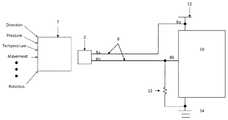
- FIG. 1is a block diagram of a system having a sensor disposed proximate to a target;
- FIG. 1Ais a block diagram of a system having a sensor disposed to sense a properties of an environment around the sensor;
- FIG. 1Bis a block diagram of a sensor to generate a signal pulse train having pulses provided in accordance with a pulse width protocol
- FIG. 1Cis a plot of an illustrative signal pulse train having pulses provided in accordance with a pulse width protocol
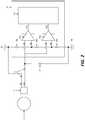
- FIG. 2is a circuit diagram of a system having a sensor and circuitry to detect a pulse stream provided by the sensor;
- FIG. 3is a timing diagram showing the sensor output for an object moving in a first direction
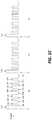
- FIG. 4is a timing diagram showing the sensor output pulse train having varying widths.
- FIG. 5is a timing diagram showing one illustrative sensor output for an object moving in the first direction.
- the present disclosureis generally directed toward a sensor capable of providing information about a target and/or the sensor itself using a formatted output signal pulse train as well as towards related methods and systems.
- the signal pulse trainincludes multiple pulses each of which may have one or more different characteristics including, but not limited to, different amplitudes and pulse widths.
- the different characteristics (e.g., position, amplitude, width) of each of the pulsesmay be used to provide a variety of information related to the target and/or the sensor itself.
- the output signal pulse trainincludes pulses in which the pulse widths may represent either device state information or data bits used to form data words. In some cases, widths and/or amplitudes of consecutive pulses within a pulse train are used to provide state information or to form data words. Thus, a single device or application may use the pulse train information for either device state or data words within different modes. For example, during a first operating mode a device or application may use device state information. In a second operating mode (e.g. a test mode), however, the device or application may use data words.
- the first operating modemay refer to operation of a device during its intended (or normal) operation or “mission” (and thus is sometimes referred to “mission mode”).
- Test modemay refer to a time period during which various components of a device are tested.
- the pulse trainincludes delimiting pulses such that a series of pulses between the delimiting pulses may be considered together to convey information (e.g. device state information or data bits used to form data words).
- a delimiting pulse followed by a series of pulses occurring before a next delimiting pulsemay be considered together to convey information (i.e. the first delimiting pulse and the following series of pulses are considered together to convey information).
- the delimiting pulsesdefine portions of a pulse train.
- the pulse trainmay be considered as having a plurality of pulse train portions comprised of a first (or delimiting) pulse followed by one or more second (or non-delimiting) pulses.
- the first pulse in each pulse train portionis generated in response to detection by the sensor of some feature of a target.
- a sensormay provide a first (or delimiter) pulse in response to detection of each edge of a plurality of teeth on an exciter wheel.
- the sensormay generate pulses in response to either a rising edge, falling edge, or, in the case of double data rate, both rising and falling edges of the exciter wheel target or in response to a magnetic differential signal.
- delimiting pulsesmay be distinguished from non-delimiting pulses by some pulse characteristic (e.g. a pulse amplitude or a pulse width characteristic).
- some pulse characteristice.g. a pulse amplitude or a pulse width characteristic.
- delimiting pulsesmay be provided having an amplitude which differs from the amplitude of non-delimiting pulses.
- the pulse trainmay represent a device state or a data word having a base number based upon a potential number of pulse widths (e.g., a base three (3) system would have three (3) potential pulse widths and more generally a base N system would have N potential widths).
- a sensor 2is disposed proximate a target object 4 (or more simply, a “target”).
- Sensor 2may be provided, for example, as a magnetic field sensor.
- sensor 2may generate a series of pulses, referred to herein as a pulse train, the characteristics and benefits of which will be described herein below.
- Sensor 2may be the same as or similar to the types described in each of U.S. Pat. No. 6,815,944, filed on Oct. 29, 2002, U.S. Pat. No. 7,026,808, filed on Sep. 23, 2004, U.S. Pat. No. 8,624,588, filed on Jul. 31, 2008, U.S. Pat. No. 9,151,771, filed on Dec. 2, 2013, U.S. Pat. No. 8,994,369, filed on Dec. 2, 2013, and U.S. Pat. No. 8,754,640, filed on Jun. 18, 2012, all of which are incorporated herein by reference in their entireties.
- Signal paths 8 a , 8 bcouple sensor 2 to a receiver 10 .
- signal paths 8 a , 8 bcouple a supply voltage 12 and a reference point (i.e., ground) 14 to sensor 2 as will be discussed in greater detail below.
- signal path 8is shown provided as a two wire line 8 a , 8 b although any signal path or transmission line suitable for transmission of a pulse train from sensor 2 to receiver 10 may be used.
- the output signal pulse train generated by sensor 2is appropriate for use in two-wire, three-wire or n+1 wire sensor solutions.
- Sensor 2is disposed within a predetermined distance from target 4 to detect characteristics and features of target 4 , such as speed and direction information.
- the particular positioning of sensor 2 with respect to target 4will, of course, depend upon the needs of the particular application or system in which the sensor 2 is being used.
- sensor 2may be adapted (and in some cases, optimized) for use in a wide variety of different applications including, but not limited to, accelerometer applications, gyroscope applications, gas sensor applications, pressure sensor applications, temperature sensor applications, bolometer sensor applications, infrared sensor applications and automotive applications.
- sensor 2may sense different properties and characteristics of the environment 7 around sensor 2 .
- sensor 2is configured to detect a direction value, pressure value, temperature value, acceleration value, movement value, rotation value, etc.
- sensor 2is configured to detect a magnetic field variation in environment 7 .
- the magnetic field variationmay be used to detect a wide variety of different properties and characteristics of the environment 7 around sensor 2 .
- the magnetic field variationmay be used to detect a direction value, rotation value, angle value, speed value, etc.
- sensor 2can be positioned at varying distances and oriented at various angles relative to target 4 based upon the needs of a particular application. In some embodiments, sensor 2 can be mounted at any angle in a plane perpendicular to a rotation of target 4 . Sensor 2 may be positioned such that a plane of least one surface of sensor 2 is parallel with a surface or edge of target 4 .
- Sensor 2is configured to generate an output signal pulse train in response to detecting characteristics and mechanical features (or more simply “features”) of target 4 .
- sensor 2may be a magnetic field sensor integrated circuit (IC).
- sensor 2may be a single-chip Hall-effect sensor IC.
- the Hall-effect sensormay have one or more Hall elements 3 .
- the Hall elements 3may be positioned along edges or at vertices of an equilateral triangle within sensor 2 .
- each of the Hall elements 3sense the magnetic profile of target 4 simultaneously but at different locations.
- sensor 2includes one or more detection circuits 5 coupled to Hall effect elements 3 .
- the one or more detection circuits 5can be configured to detect at least one of (a) a parameter of an environment in which the sensor is disposed, (b) the first feature of the target object, and (c) a parameter of a relationship between the sensor and the target object.
- the one or more detection circuits 5can be configured to detect a direction of the target object 4 relative to sensor 2 and airgap properties between target object 4 and sensor 2 .
- the one or more detection circuitscan be configured to detect a magnetic field variation in the environment in which sensor 2 is disposed.
- Sensor 2may be used to communicate information for a variety of different sensors.
- sensor 2may be adapted for used in an accelerometer, a gyrometer, a gas sensor, a pressure sensor, or a temperature sensor.
- Sensor 2may detect a condition of an environment in which the sensor is disposed (e.g. a condition experienced by sensor 2 ) and generate the output signal pulse train to provide information corresponding to this condition.
- the detected conditionis a change in a magnetic field.
- the detected conditionincludes at least one of: a change in temperature, a change in pressure, a change in a gas level, a change in a radiation level or a change in a change in speed.
- the output signal pulse trainmay be initiated by a change in the condition that falls below or above a predetermined threshold or outside a predetermined acceptable range of values. For example, a temperature experienced by sensor 2 may fall below or above a predetermined threshold or a pressure experienced by sensor 2 may fall below or above a predetermined threshold.
- sensor 2may generate the output signal pulse train to indicate this change in condition.
- sensor 2may generate the output signal pulse train as part of a built-in test (BIT) or in response to a test probe applied to a particular device.
- BITbuilt-in test
- signal paths 8 a , 8 bcouple sensor 2 to receiver 10 , supply voltage 12 and reference point (i.e., ground) 14 .
- a first signal path 8 ais coupled to supply voltage 12 and receiver 10 and a second signal path 8 b is coupled to receiver 10 and to reference point 14 through a resistor 22 .
- the output signal pulse train generated by sensor 2propagates to receiver 10 via one or both of signal paths 8 a , 8 b .
- the output signal pulse trainpropagates to receiver 10 via signal path 8 b while in other embodiments, the output signal pulse train propagates to receiver 10 via signal path 8 a.
- Receiver 10receives the pulse train provided thereto and in response thereto determines device state information and/or data bit values (or word values). In one embodiment, receiver 10 identifies a first (or delimiter) pulse in the pulse train by detecting a particular pulse characteristic (e.g., pulse amplitude or pulse width or some other pulse characteristic) and then begins measuring pulse widths of the following (non-delimiter) pulses. As will be described in detail further below, the widths of both high and low pulses are used to convey information via the pulse train.
- a particular pulse characteristice.g., pulse amplitude or pulse width or some other pulse characteristic
- an output signal pulse train 9includes a plurality of pulse train portions, here three (3) pulse train portions, 9 a - 9 c .
- the beginning of each pulse train portion 9 a - 9 cis identified by first (or delimiter) pulses 11 a - 11 c .
- First (or delimiter) pulse in the output signal pulse trainmay be identified by a pulse characteristic which differs from a like characteristic of every other non-delimiter pulse in the output signal pulse train. In the illustrative embodiment of FIG. 1C , for example, an amplitude characteristic is used.
- first pulses 11 a - 11 c in the output signal pulse train portions 9 a - 9 care provided having an amplitude which differs from the amplitude of the remaining non-delimiter pulses (e.g. pulses 13 a - 13 o in the pulse train portion 9 a , for example).
- first (or delimiter) pulsesare here shown having an amplitude which is greater than an amplitude of all other pulses in the pulse train (or greater than a predetermined amplitude threshold value) in other embodiments, it may be desirable or necessary that first (or delimiter) pulses are provided having an amplitude which is less than an amplitude of all other pulses in the pulse train (or less than an amplitude threshold value).
- a pulse width characteristic(rather than an amplitude characteristic) may be used to identify the first (or delimiter) pulse.
- each first (or delimiter) pulse in the output signal pulse trainmay be identified by having a pulse width which differs from the pulse width of the non-delimiter pulses in the pulse train.
- the delimiter (or first) pulsemay be provided having a pulse width which is either less than or greater than a width of all other non-delimiter pulses in the pulse train or greater or less than a predetermined pulse width threshold value.
- the output signal pulse trainmay include data associated with detected characteristics and/or features of target 4 or with characteristics and/or features associated with the sensor itself.
- the datamay be transmitted in different forms, including as a current signal, a voltage signal value, an RF signal characteristic value (e.g. a current voltage, frequency, or phase characteristic), etc.
- Receiver 10includes a pair of comparison devices (e.g. comparators) 16 a , 16 b and a processor 20 (e.g., state machine, digital block, controller, etc.). Comparison devices 16 a , 16 b have two inputs that are coupled to sensor 2 through signal paths 8 . An output 17 a , 17 b of each comparison device 16 a , 16 b is coupled to processor 20 .
- comparison devices 16 a , 16 bhave two inputs that are coupled to sensor 2 through signal paths 8 .
- An output 17 a , 17 b of each comparison device 16 a , 16 bis coupled to processor 20 .
- first signal path 8 acouples supply voltage 12 to a first input of first comparison device 16 a and second comparison device 16 b . While a pulse width pulse train such as that described in FIG. 1C is provided to receiver 10 via signal path 8 b .
- Supply voltage 12may provide a reference voltage to first and second comparison devices 16 a , 16 b .
- resistive elements 18 a , 18 b , 18 care disposed along the first signal path 8 a between supply voltage 12 and a first input of each of first and second comparison devices 16 a , 16 b .
- each resistive element 18 a , 18 b , 18 cprovides a voltage drop to generate and provide a predetermined reference voltage to first and second comparison devices 16 a , 16 b.
- a first resistor 18 ais disposed between supply voltage 12 and first input of first comparison device 16 a .
- a second resistor 18 bis disposed between the first input of first comparison device 16 a and the first input of second comparison device 16 b .
- a third resistor 18 cis disposed between the first input of second comparison device 16 b and a reference point 14 .
- Resistive elements 18 a , 18 b , 18 cmay be sized to various values according to a particular application and the properties of the components in a corresponding sensor system.
- first and second comparison devices 16 a , 16 bcompare the predetermined reference voltage to data output (i.e., an output signal pulse train) generated by sensor 2 .
- the data outputmay be transmitted in different forms, including as a current value, a voltage value or a RF signal.
- second signal path 8 bprovides data output (e.g., characteristics and features associated with target 4 and/or characteristics and features associated with sensor 2 ) from sensor 2 to first and second comparison devices 16 a , 16 b .
- second signal path 8 bcouples sensor 2 to a second input of each of first and second comparison devices 16 a , 16 b .
- first signal path 8 aprovides data output from sensor 2 to first and second comparison devices 16 a , 16 b and second signal path 8 b couples supply voltage 12 to first and second comparison device 16 a , 16 b.
- second signal path 8 bis coupled to ground (i.e., reference point 14 ) through a load resistor 22 .
- Load resistor 22is disposed between a node of second signal path 8 b and reference point 14 .
- the node of second signal path 8 bis disposed between the output of sensor 2 and the second input of first and second comparison devices 16 a , 16 b .
- Load resistor 22may be used to modify or set an output value of sensor 2 that is provided to the second input of first and second comparison devices 16 a , 16 b to a predetermined level.
- load resistor 22provides a voltage drop corresponding to a product of an output of sensor 2 and a value of resistor 22 .
- Load resistor 22may be sized to various values according to a particular application and the properties of the components in a corresponding sensor system.
- comparison devices 16 a , 16 bare arranged to form a window comparator. However, it should be appreciated that comparators may be organized in other arrangements depending upon a particular application.
- First and second comparison devices 16 a , 16 bcompares two inputs (e.g., two voltages, two current, two radio frequency (RF) signals) and output a digital signal. Outputs of first and second comparison devices 16 a , 16 b are coupled to processor 20 .
- Processor 20can be configured to compare the output 17 a of first comparison device 16 a to the output 17 b of second comparison device 16 b.
- Processor 20may be a logic or state machine and be configured to receive outputs 17 a , 17 b and determine device state information and/or data bits. For example, processor 20 is configured to determine a logic value for each of the measured widths.
- Processor 20may be any computing device suitable for the execution of a computer program include, by way of example, both general and special purpose microprocessors, and any one or more processors of any kind of digital computer.
- processor 20can also include, or be operatively coupled to receive data from or transfer data to, or both, one or more memory systems or mass storage devices for storing data, e.g., magnetic, magneto optical disks, or optical disks.
- Processor 20 and the memorycan be supplemented by, or incorporated in, special purpose logic circuitry.
- processor 20can be configured to measure widths and amplitudes of each pulse in an output signal pulse train.
- Processor 20may identify a particular pulse in a pulse train portion (e.g., a first pulse, a second pulse, a third pulse, etc.) based upon the pulse having an amplitude greater than or equal to an amplitude threshold.
- the amplitude thresholdmay be a threshold value, amplitude, level or height used to identify the particular pulse in the output signal pulse train portion.
- the receiverbegins measuring the pulses widths in response to a detected first feature of target 4 reaching a first amplitude threshold.
- the first featuremay be identified via one or more predetermined characteristics of a target (e.g., a leading edge of a tooth or an exciter wheel).
- Processor 20is configured to determine the logic value for each of the measured widths and determine at least one of a device state or a data word based on the determined logic values of the two or more pulses.
- processor 20is configured to generate time out functions in response to delays in sensor 2 detecting a second feature or subsequent feature of target 4 after a predetermined time threshold.
- a portion of an illustrative output signal pulse train 50(hereinafter “output”), comprising a plurality of portions 51 a , 51 b , 51 c comprising respective ones of pulses 52 a - 52 c , 54 a - 54 c , 56 a - 56 c provided in accordance with a predetermined protocol is generated in response to a sensor (not shown) detecting one or more characteristics and/or one or more features (e.g., one or more mechanical features) of a target 30 .
- Pulses 52 a - 52 cmay be collectively referred to herein as pulse 52 or first pulse 52 .
- Pulses 54 a - 54 cmay be collectively referred to herein as pulse 54 or second pulse 54 .
- Pulses 56 a - 56 cmay be collectively referred to herein as pulse 56 or third pulse 56 .
- target 30is shown as a portion of a gear tooth wheel.
- output 50is generated in response to target 30 moving in a first direction (indicated by reference arrow 35 ) relative to the sensor.
- direction 35is sometimes referred to as a right movement or right rotation of the target 30 relative to the sensor.
- sensor 2may generate output 50 in response to detecting characteristics and features of target 30 . It should be appreciated that output 50 may be generated in response to target 30 moving in any direction relative to the sensor (i.e., left, right, toward or away from the sensor).
- target 30has a plurality of teeth 34 , each of which has a first edge 32 and a second edge 36 .
- a sensore.g., sensor 2 of FIGS. 1-2
- the sensorwhen teeth 34 of target 30 pass by a sensor (e.g., sensor 2 of FIGS. 1-2 ), the sensor generates output 50 .
- target 30may be a ring magnet and when a pole pair of the ring magnet passes by the sensor, the sensor generates output 50 .
- target 30is a magnetic latch or switch
- the sensorwhen an edge of the magnetic latch passes by the sensor, the sensor generates output 50 . It should be understood that target 30 may be a variety of different devices and the sensor may generate output 50 in response to various features of target 30 .
- Output 50comprises a plurality of pulse train portions 51 a , 51 b , 51 c , (collectively referred to herein as portions 51 ) with each portion 51 including respective ones of the plurality of pulses 52 , 54 , 56 (i.e., first pulse 52 , second pulse, 54 , third pulse 56 ).
- Each pulse 52 , 54 , 56is generated in accordance with a pulse width protocol which allows coding of information about the target 30 and/or sensor, including but not limited to speed, direction, positional data, diagnostic data, airgap data, device status and test mode information.
- Each of the plurality of pulses 52 , 54 , 56 within a single portion 51can have varying amplitudes and varying widths.
- the amplitude and width of a pulse, as well as the positionmay be used to code the information and indicate specific characteristics and/or features of a target 30 and/or a sensor generating the pulse train.
- first pulses 52may be used to convey different information than second pulses 54 or third pulses 56 .
- second pulses 54 and third pulses 56may be used to convey different information from each other and first pulses 52 .
- each of the pulses 52 , 54 , 56may be generated with a predetermined amplitude to indicate specific characteristics and/or features of or associated with a target and/or sensor. It should be understood that amplitude as used herein may refer to a level or height of pulses 52 , 54 , 56 in output 50 . Pulse amplitude may also be used to identify a position of the pulse in the output signal pulse train (e.g., first pulses 52 , second pulses 54 , third pulses 56 ). For example, first pulse 52 may be generated in response to a first feature (e.g., an edge 32 , 36 ,) of target 30 ).
- a first featuree.g., an edge 32 , 36 ,
- the first pulse 52is generated with a first amplitude 60 (e.g., first level, high level) that is equal to or greater than a first amplitude threshold.
- the first amplitude thresholdis a threshold value, level or height that is used to indicate that pulse 52 is the first pulse in output signal pulse train portions 51 a , 51 b , 51 c .
- first pulse 52 in each portion 51 a , 51 b , 51 ccorresponds to either a rising edge 32 or falling edge 36 of a tooth 34 .
- first pulse 52 having the first amplitude 60indicates the beginning of a new portion 51 of output signal pulse train 50 .
- the rising edge of first pulse 52represents additional data such as target speed or frequency.
- the time between first pulse 52 a of first portion 51 a and first pulse 52 b of second portion 51 bmay be used to determine the speed or frequency at which the target 30 is moving or rotating.
- a second pulse 54may be generated in response to a second feature or other characteristics of target 30 .
- second pulse 54is generated having a second amplitude 62 (e.g., second level, low level) that is greater than or equal to a second amplitude threshold.
- the second amplitude thresholdis a threshold value, level or height that is used to indicate that pulse 54 is the second pulse in output signal pulse train portions 51 a , 51 b , 51 c .
- the second amplitude 62may be inverted (e.g., low pulse, low amplitude) with respect to first amplitude 60 .
- second pulse 54follows first pulse 52 and its amplitude 62 falls to a reduced (or sometimes minimum) amplitude of output 50 .
- second pulse 54is inverted as compared with first pulse 52 . It should thus be understood that the widths of both high and low portions of output pulse train 50 are used to convey information in the pulse width protocol.
- third pulse 56may be generated in response to a third feature or characteristic of target 30 .
- third pulse 56is generated with a third amplitude 64 (e.g., third level, middle level) that is greater than or equal to a third amplitude threshold (i.e., middle amplitude).
- the third amplitude thresholdis a threshold value, level or height that is used to indicate that pulse 56 is the third pulse in output signal pulse train portions 51 a , 51 b , 51 c .
- the third amplitude 64may be less than first amplitude 60 and inverted with respect to second amplitude 62 .
- third pulse 56follows second pulse 54 and its amplitude rises to a third amplitude 64 , which is less than the first amplitude 60 of first pulse 52 .
- FIG. 3only shows each portion 51 of output 50 having three pulses 52 , 54 , 56 , it should be appreciated that any number of pulses may be generated within a portion 51 of output 50 depending upon a movement or other characteristic of a target and the needs of a particular application.
- output 50may include N pulses or N bits in response to a detected feature of target 30 .
- a portion of an output pulse train 70includes pulse train portion 71 a , 71 b .
- Each of the first pulses 72 a - 72 b , second pulses 74 a - 74 b , third pulses 76 a - 76 b (collectively referred to herein as pulses 72 , 74 , 76 ) in first and second pulse train portions 71 a , 71 bmay be generated having a selected one of pulse widths 80 a - 80 c .
- the particular width of each pulsecorresponds to a particular bit value which may be used to indicate a specific feature of a target and/a sensor or may be used to form a portion of a digital word.
- the width 80 a - 80 c of each pulsemay thus be used to provide information such as direction information, airgap properties, a sensor mode, a sensor position and diagnostics data (e.g., automobile safety integrity level (ASIL) information).
- ASILautomobile safety integrity level
- each pulse 72 , 74 , 76may have up to N different widths.
- each pulse 72 , 74 , 76can have one of three different widths, including a first width 80 a , a second width 80 b and a third width 80 c .
- the widths of pulses 72 , 74 , 76may be the same.
- the widths of each pulse 72 , 74 , 76may be different.
- the widths of two or more pulses 72 , 74 , 76may be the same.
- the position of each pulseis first determined (e.g. relative to the delimiter pulse, here corresponding to first pulse 72 followed by second pulse 74 and third pulse 76 ) and then the width 80 of the pulse is determined. For example, after the first feature of the target is detected and pulse 72 is identified as the first pulse, a width 80 (e.g., first width 80 a , second width 80 b , third width 80 c ) of first pulse 72 and each successive pulse 74 , 76 may be measured.
- the width 80can be used in combination with the position of the particular pulse to provide specific information. For example, first pulse 72 and second pulse 74 may have the same width 80 but provide different information.
- each pulse 72 , 74 , 76may be designated or assigned to provide predetermined information, such as state information.
- Each statemay correspond to a characteristic or feature of a target or a sensor.
- state informationmay be generated and used for applications functioning in mission mode (e.g., normal mode) and provide details on particular devices during device operation.
- first pulse 72is designated to provide direction information of a target
- second pulse 74is designated to provide airgap information between the target and a sensor
- third pulse 76is designated to provide sensor mode information.
- each pulse 72 , 74 , 76is shown having one of three widths 80 a , 80 b , 80 c .
- output pulse train portions 71 a , 71 beach have three pulses (i.e.
- each output pulse train portion 71 a , 71 bcan provide up to nine different states or types of information.
- first pulse 72may be generated in response to a first feature (e.g., first rising edge or first falling edge) of a target with one of three widths 80 a , 80 b , 80 c (here indicated by the dashed downward arrow).
- first pulse 72is designated to provide direction in which the target is moving.
- first width 80 aindicates a positive direction
- second width 80 bindicates a negative direction
- third width 80 cindicates no direction.
- Second pulse 74can be designated to provide airgap information between a target and sensor.
- second pulse 74 with a first width 80 aindicates an airgap feature in a predetermined acceptable range
- a second width 80 bindicates an airgap feature outside the predetermined acceptable range and may cause an alert or flag to be issued.
- second pulse 74 having a third pulse 80 cmay indicate an airgap reserve and an airgap reserve (AR) signal can be generated.
- airgap reservemay refer to a reserve bit or extra bit and be reserved for a future use.
- Third pulse 76can be designated to provide sensor mode information.
- third pulse 76 with a first width 80 aindicates sensor mode 0, while third pulse 76 with a second width 80 b indicates sensor mode 1, and third pulse 76 with a third width 80 c indicates sensor mode 2.
- Table 1provides but one illustrative embodiment and that any number of states and types of information can be designated according the number of pulses in output 70 and the type of information a particular device or application requests to be monitored or detected (e.g., diagnostics, ASIL, device status, etc.,).
- pulse widths 80 a , 80 b , 80 c of each of the pulses 72 , 74 , 76represent a corresponding & logic value, such as a logical data bit.
- the widths 80 of each pulse 72 , 74 , 76 in output 70may be measured and the corresponding logic value determined for each pulse 72 , 74 , 76 .
- a first width 80 amay be a first logic value
- a second width 80 bmay be a second logic value
- a third width 80 cmay be a third logic value in a digital data stream.
- output 70can be represented as a digital data string (i.e., a stream of data bits with each of the data bits having one of three logic values).
- a stream of data bitscan be generated with each of the data bits having one of two logical values.
- the widths 80may be measured as the pulses 72 , 74 , 76 are received, for example as they are received by receiver 10 from sensor 2 of FIGS. 1-2 . In other embodiments, the widths 80 may be measured once an entire portion 71 of output 70 has been transmitted from a sensor to a receiver.
- portion 71 of output 70may be a serial data train representing a data word with a base N, corresponding to N number of potential pulse widths 80 (here shown as a base 3 with 3 potential pulse widths).
- Each wordcan be a code associated with a characteristic or feature of a target or a sensor.
- a pulse width protocolbase 3 for generating data words is provided.
- output 70 having three pulses 72 , 74 , 76 , with each pulse having three potential pulse widths 80 a , 80 b , 80 ccan provide up to twenty different logic values (i.e., code) or data words.
- Each logic valuemay be associated with test or diagnostics information for a device or application.
- logic valuescan be associated with output codes for a built-in test (BIT) or a test at a probe of a device or application.
- Logic valuesmay be associated with an output 70 received from various types of sensors, including but not limited to an accelerometer, a gyroscope, a gas sensor, a pressure sensor, and a temperature sensor.
- a receivere.g., receiver 10 of FIGS. 1-2
- output 70may have a maximum frequency limit or bound depending on the number of pulses 72 , 74 , 76 generated in portion 71 and the maximum width 80 used for each pulse in the respective portion 71 .
- the maximum frequency of a target or data streamis based on the total number of pulses in portion 71 of output signal 70 multiplied by the maximum pulse width 80 . If the target or data stream exceeds this frequency there may be data collision between adjacent portions 71 , such as between a first portion 71 a and a second portion 71 b .
- the maximum frequency limitestablishes a threshold to avoid data collision within output 70 .
- a time out functionmay be generated to ignore the first rising edge of 72 a .
- receiver 10 of FIGS. 1-2identifies first edge of first pulse 72 a it may initiate a timer with a predetermined time threshold to track or count until the next rising edge is identified in the data bits.
- the predetermined time thresholdlimits the amount of time the timer counts to identify potential edge error detections. Thus, if the next rising edge is not identified within the predetermined time threshold, the receiver may flag the first rising edge as an edge error and stop the timer until a next rising edge is identified.
- the sensor system 2can quickly recover from the error signal and also identify edge errors.
- the predetermined time thresholdmay allow the system not to get stuck in a continuous timer or lock up when an edge error is detected.
- the predetermined time thresholdmay be used in consecutive pulse widths to identify errors within a single portion 71 of output signal 70 .
- an output pulse portion 90includes a first pulse 92 having a width 80 b corresponding to a logic value 1, a second pulse 94 having a width 80 a corresponding to a logic value 0 and a third pulse 96 having a width 80 c corresponding to a logic value 2.
- illustrative pulse train portion 90comprises a series of three (3) pulses representing logic values 1, 0, 2 respectively.
- a first pulse 92 having logic value 1indicates that the direction of the target is negative with respect to the sensor.
- a second pulse 94 having logic value 0indicates that the airgap between the target and sensor is within a predetermined acceptable range.
- a third pulse 96 having logic value 2indicates that the sensor is in mode 2 or some other function.
- This datamay correspond to a particular diagnostics, test function or some other function.
- output pulse train portion 90may be used as both state and/or word information depending on a particular application using the information.
- both state information and wordsmay be used simultaneously generated and transmitted on the same signal path for different applications.
- output 90may be received and translated by a receiver. The receiver may translate the information and provide it to different applications.
- a first application running in mission modemay interpret the logic values 1, 0, 2 as state information, including the negative direction of the target, the acceptable airgap properties and sensor mode 2.
- a second application running in test modemay interpret the same logic values (1, 0, 2) as code 7 or a 7 th word.
- magnetic field sensoris used to describe a circuit that uses a magnetic field sensing element, generally in combination with other circuits.
- Magnetic field sensorsare used in a variety of applications, including, but not limited to, an angle sensor that senses an angle of a direction of a magnetic field, a current sensor that senses a magnetic field generated by a current carried by a current-carrying conductor, a magnetic switch that senses the proximity of a ferromagnetic object, a rotation detector that senses passing ferromagnetic articles, for example, magnetic domains of a ring magnet or a ferromagnetic target (e.g., gear teeth) where the magnetic field sensor is used in combination with a back-biased or other magnet, and a magnetic field sensor that senses a magnetic field density of a magnetic field.
- an angle sensorthat senses an angle of a direction of a magnetic field
- a current sensorthat senses a magnetic field generated by a current carried by a current-carrying conductor
- a magnetic switchthat
- magnetic field sensing elementis used herein, to describe a variety of electronic elements that can sense a magnetic field.
- the magnetic field sensing elementcan be, but is not limited to, a Hall effect element, a magnetoresistance element, or a magnetotransistor.
- Hall effect elementsfor example, a planar Hall element, a vertical Hall element, and a Circular Vertical Hall (CVH) element.
- magnetoresistance elementsfor example, a semiconductor magnetoresistance element such as Indium Antimonide (InSb), a giant magnetoresistance (GMR) element, for example, a spin valve, an anisotropic magnetoresistance element (AMR), a tunneling magnetoresistance (TMR) element, and a magnetic tunnel junction (MTJ).
- the magnetic field sensing elementmay be a single element or, alternatively, may include two or more magnetic field sensing elements arranged in various configurations, e.g., a half bridge or full (Wheatstone) bridge.
- the magnetic field sensing elementmay be a device made of a type IV semiconductor material such as Silicon (Si) or Germanium (Ge), or a type III-V semiconductor material like Gallium-Arsenide (GaAs) or an Indium compound, e.g., Indium-Antimonide (InSb).
- a type IV semiconductor materialsuch as Silicon (Si) or Germanium (Ge)
- a type III-V semiconductor materiallike Gallium-Arsenide (GaAs) or an Indium compound, e.g., Indium-Antimonide (InSb).
- some of the above-described magnetic field sensing elementstend to have an axis of maximum sensitivity parallel to a substrate that supports the magnetic field sensing element, and others of the above-described magnetic field sensing elements tend to have an axis of maximum sensitivity perpendicular to a substrate that supports the magnetic field sensing element.
- planar Hall elementstend to have axes of sensitivity perpendicular to a substrate
- metal based or metallic magnetoresistance elementse.g., GMR, TMR, AMR
- vertical Hall elementstend to have axes of sensitivity parallel to a substrate.
- processoris used to describe an electronic circuit that performs a function, an operation, or a sequence of operations.
- the function, operation, or sequence of operationscan be hard coded into the electronic circuit or soft coded by way of instructions held in a memory device.
- a “processor”can perform the function, operation, or sequence of operations using digital values or using analog signals.
- the “processor”can be embodied in an application specific integrated circuit (ASIC), which can be an analog ASIC or a digital ASIC. In some embodiments, the “processor” can be embodied in a microprocessor with associated program memory. In some embodiments, the “processor” can be embodied in a discrete electronic circuit, which can be an analog or digital.
- ASICapplication specific integrated circuit
- moduleis sometimes used to describe a “processor.”
- a processorcan contain internal processors or internal modules that perform portions of the function, operation, or sequence of operations of the processor.
- a modulecan contain internal processors or internal modules that perform portions of the function, operation, or sequence of operations of the module.
- embodiments of the disclosure hereinmay be configured as a system, method, or combination thereof. Accordingly, embodiments of the present disclosure may be comprised of various means including entirely of hardware, entirely of software, or any combination of hardware and software. Furthermore, embodiments of the present disclosure may take the form of a computer program product on a computer-readable storage medium having computer readable program instructions (e.g., computer software) embodied in the storage medium. Any suitable non-transitory computer-readable storage medium may be utilized.
Landscapes
- Physics & Mathematics (AREA)
- Nonlinear Science (AREA)
- Condensed Matter Physics & Semiconductors (AREA)
- General Physics & Mathematics (AREA)
- Transmission And Conversion Of Sensor Element Output (AREA)
- Measurement Of Length, Angles, Or The Like Using Electric Or Magnetic Means (AREA)
Abstract
Description
| TABLE 1 |
| Pulse Width Protocol (base 3) States |
| Example | Pulse | ||
| 1 | +Direction | First Pulse = 0 | |
| 2 | −Direction | First Pulse = 1 | |
| 3 | No Direction | First Pulse = 2 | |
| 4 | Airgap in range | Second Pulse = 0 | |
| 5 | Airgap Flag | Second Pulse = 1 width | |
| 6 | Reserve | Second Pulse = 2 | |
| 7 | Sensor Mode 0 | Third Pulse = 0 | |
| 8 | Third Pulse = 1 | ||
| 9 | Third Pulse = 2 width | ||
| TABLE 2 |
| Pulse Width Protocol (base 3) Data Word |
| Code | First Pulse | Second Pulse | Third Pulse | ||
| 0 | 0 | 0 | 0 | ||
| 1 | 0 | 1 | 0 | ||
| 2 | 0 | 2 | 0 | ||
| 3 | 0 | 1 | 1 | ||
| 4 | 0 | 1 | 2 | ||
| 5 | 0 | 2 | 1 | ||
| 6 | 0 | 2 | 2 | ||
| 7 | 1 | 0 | 2 | ||
| 8 | 1 | 1 | 0 | ||
| 9 | 1 | 2 | 0 | ||
| 10 | 1 | 1 | 1 | ||
| 11 | 1 | 1 | 2 | ||
| 12 | 1 | 2 | 1 | ||
| 13 | 1 | 2 | 2 | ||
| 14 | 2 | 0 | 0 | ||
| 15 | 2 | 1 | 0 | ||
| 16 | 2 | 2 | 0 | ||
| 17 | 2 | 1 | 1 | ||
| 18 | 2 | 1 | 2 | ||
| 19 | 2 | 2 | 1 | ||
| 20 | 2 | 2 | 2 | ||
Claims (30)
Priority Applications (3)
| Application Number | Priority Date | Filing Date | Title |
|---|---|---|---|
| US15/010,453US10495700B2 (en) | 2016-01-29 | 2016-01-29 | Method and system for providing information about a target object in a formatted output signal |
| PCT/US2017/012241WO2017131934A1 (en) | 2016-01-29 | 2017-01-05 | Method and system for providing information about a target object in a formatted output signal |
| EP17702179.7AEP3408937B1 (en) | 2016-01-29 | 2017-01-05 | Method and system for providing information about a target object in a formatted output signal |
Applications Claiming Priority (1)
| Application Number | Priority Date | Filing Date | Title |
|---|---|---|---|
| US15/010,453US10495700B2 (en) | 2016-01-29 | 2016-01-29 | Method and system for providing information about a target object in a formatted output signal |
Publications (2)
| Publication Number | Publication Date |
|---|---|
| US20170219662A1 US20170219662A1 (en) | 2017-08-03 |
| US10495700B2true US10495700B2 (en) | 2019-12-03 |
Family
ID=57915083
Family Applications (1)
| Application Number | Title | Priority Date | Filing Date |
|---|---|---|---|
| US15/010,453Active2038-02-17US10495700B2 (en) | 2016-01-29 | 2016-01-29 | Method and system for providing information about a target object in a formatted output signal |
Country Status (3)
| Country | Link |
|---|---|
| US (1) | US10495700B2 (en) |
| EP (1) | EP3408937B1 (en) |
| WO (1) | WO2017131934A1 (en) |
Cited By (6)
| Publication number | Priority date | Publication date | Assignee | Title |
|---|---|---|---|---|
| US12107710B2 (en) | 2020-11-19 | 2024-10-01 | Allegro Microsystems, Llc | Sensor signaling of absolute and incremental data |
| US12104900B2 (en) | 2022-09-29 | 2024-10-01 | Allegro Microsystems, Llc | Sensor with estimated real-time parameter data |
| US12266603B2 (en) | 2022-05-03 | 2025-04-01 | Allegro Microsystems, Llc | Semiconductor device to reduce signal loss in a transmission line |
| US12332273B2 (en) | 2022-05-18 | 2025-06-17 | Allegro Microsystems, Llc | High resolution sensing protocol |
| US12348243B2 (en) | 2022-05-18 | 2025-07-01 | Allegro Microsystems, Llc | Method and apparatus for transmitting data concurrently with a pulse-encoded signal |
| US12407549B2 (en) | 2023-11-06 | 2025-09-02 | Allegro Microsystems, Llc | Output signal protocol |
Families Citing this family (24)
| Publication number | Priority date | Publication date | Assignee | Title |
|---|---|---|---|---|
| WO2018048768A1 (en) | 2016-09-08 | 2018-03-15 | Allegro Microsystems, Llc | Signalling of faults in a speed sensor |
| DE102016125183B4 (en) | 2016-12-21 | 2022-01-27 | Infineon Technologies Ag | Devices for encoding and decoding wheel speed sensor signals and methods for communicating encoded wheel speed sensor signals |
| US10436606B2 (en) | 2017-07-20 | 2019-10-08 | Allegro Microsystems, Llc | Magnetic field sensor to detect speed and direction of angular rotation of a rotating magnetic structure |
| US10480957B2 (en) | 2017-07-20 | 2019-11-19 | Allegro Microsystems, Llc | Magnetic field sensor to detect direction of angular rotation of a rotating magnetic structure, speed of the rotating magnetic structure or fault |
| US10473486B2 (en) | 2017-07-20 | 2019-11-12 | Allegro Microsystems, Llc | Duty cycle of an output signal of a magnetic field sensor to detect speed and direction of angular rotation of a rotating magnetic structure or a fault |
| US10598514B2 (en) | 2017-07-20 | 2020-03-24 | Allegro Microsystems, Llc | Magnetic field sensor to detect speed of angular rotation of a rotating magnetic structure, direction of the rotating magnetic structure or fault |
| US10571301B2 (en) | 2017-07-20 | 2020-02-25 | Allegro Microsystems, Llc | Frequency of an output signal of a magnetic field sensor to detect speed and direction of angular rotation of a rotating magnetic structure or a fault |
| US10782366B2 (en) | 2017-10-11 | 2020-09-22 | Allegro Microsystems, Llc | Multi-channel sensor output signal protocols |
| US10656170B2 (en) | 2018-05-17 | 2020-05-19 | Allegro Microsystems, Llc | Magnetic field sensors and output signal formats for a magnetic field sensor |
| US10598739B2 (en) | 2018-06-18 | 2020-03-24 | Allegro Microsystems, Llc | Magnetic field sensors having virtual signals |
| US10908229B2 (en) | 2018-06-18 | 2021-02-02 | Allegro Microsystems, Llc | Regulation of coefficients used in magnetic field sensor virtual signal generation |
| US10578679B2 (en) | 2018-06-18 | 2020-03-03 | Allegro Microsystems, Llc | Magnetic field sensors having virtual signals |
| US10866118B2 (en) | 2018-06-18 | 2020-12-15 | Allegro Microsystems, Llc | High resolution magnetic field sensors |
| US10725122B2 (en) | 2018-07-20 | 2020-07-28 | Allegro Microsystems, Llc | Ratiometric sensor output topology and methods |
| DE102018215938B4 (en)* | 2018-09-19 | 2024-11-07 | Infineon Technologies Ag | high-resolution mode for a magnetic field sensor |
| US11686597B2 (en) | 2019-06-07 | 2023-06-27 | Allegro Microsystems, Llc | Magnetic field sensors and output signal formats for magnetic field sensors |
| US11942831B2 (en) | 2020-01-15 | 2024-03-26 | Allegro Microsystems, Llc | Three-phase BLDC motor driver/controller having diagnostic signal processing |
| US11194004B2 (en) | 2020-02-12 | 2021-12-07 | Allegro Microsystems, Llc | Diagnostic circuits and methods for sensor test circuits |
| US11029370B1 (en) | 2020-05-22 | 2021-06-08 | Allegro Microsystems, Llc | Sensor output control methods and apparatus |
| US11762043B2 (en) | 2021-03-11 | 2023-09-19 | Allegro Microsystems, Llc | High resolution magnetic field sensors |
| US11885645B2 (en) | 2021-06-17 | 2024-01-30 | Allegro Microsystems, Llc | Supply voltage configurable sensor |
| CN113873717A (en)* | 2021-09-29 | 2021-12-31 | 擎茂微电子(深圳)有限公司 | Data control protocol for controlling LED lamp string by power supply carrier |
| DE102021212324B4 (en)* | 2021-11-02 | 2024-10-17 | Continental Automotive Technologies GmbH | Method for evaluating wheel sensor signals, arrangement therefor and braking system comprising the arrangement |
| DE102022206825A1 (en) | 2022-07-04 | 2024-01-04 | Continental Automotive Technologies GmbH | Wheel speed sensor interface with Manchester protocol |
Citations (102)
| Publication number | Priority date | Publication date | Assignee | Title |
|---|---|---|---|---|
| US3304434A (en) | 1965-06-01 | 1967-02-14 | Bunker Ramo | Position control system employing pulse producing means indicative of magnitude and direction of movement |
| JPS4880874A (en) | 1972-02-03 | 1973-10-29 | ||
| DE2518054A1 (en) | 1975-04-23 | 1976-11-04 | Siemens Ag | Detector for linear motion or direction of rotation - with hysteresis switching stage to detect direction of motion has differential stage output in series with hysteresis stage |
| GB2018538A (en) | 1978-04-05 | 1979-10-17 | Hawker Siddeley Dynamics Eng | Apparatus for the treatment of frequency signals |
| US4225939A (en) | 1976-04-16 | 1980-09-30 | Pioneer Electronic Corporation | Bidirectional data communication system |
| US4283679A (en) | 1978-04-18 | 1981-08-11 | Nippon Electric Co., Ltd. | Rotational direction detection device for a motor or the like |
| US4513403A (en) | 1982-08-04 | 1985-04-23 | Exploration Logging, Inc. | Data encoding and synchronization for pulse telemetry |
| US4642555A (en) | 1985-01-31 | 1987-02-10 | Sperry Corporation | Differential capacitance detector |
| US4649796A (en) | 1986-06-18 | 1987-03-17 | The United States Of America As Represented By The Secretary Of The Army | Method and apparatus for setting a projectile fuze during muzzle exit |
| DE3535842A1 (en) | 1985-10-08 | 1987-04-09 | Bosch Gmbh Robert | SPEED METER SWITCHING |
| WO1988009026A1 (en) | 1987-05-15 | 1988-11-17 | SSD Limited | Improvements relating to rotary encoders |
| JPS63300911A (en) | 1987-05-30 | 1988-12-08 | Yaskawa Electric Mfg Co Ltd | Multi-rotation absolute value encoder |
| US4893027A (en) | 1986-09-25 | 1990-01-09 | Gebhard Balluff Fabrik Feinmechanischer Erzeugnisse Gmbh & Co. | Proximity switch insensitive to interference fields |
| JPH02116753A (en) | 1988-10-26 | 1990-05-01 | Mitsubishi Electric Corp | Rotation direction detection device |
| JPH02149013A (en) | 1988-11-30 | 1990-06-07 | Toshiba Corp | oscillation circuit |
| JPH0329817A (en) | 1989-06-28 | 1991-02-07 | Fanuc Ltd | Wireless manual encoder |
| US5019773A (en) | 1988-08-24 | 1991-05-28 | Hitachi, Ltd. | Method and apparatus for detecting positions and/or speed of a moving body using two phase signals |
| DE4031560A1 (en) | 1990-10-05 | 1992-04-09 | Dieter Prof Dr Ing Seitzer | Integrated current sensor for current limiting and measuring - has components sensitive to magnetic field and excitation paths formed by film technique on substrate |
| US5138640A (en) | 1990-07-12 | 1992-08-11 | Siemens Aktiengesellschaft | Circuit configuration for improving the resolution of successive pulsed signals over time |
| US5244834A (en) | 1989-05-10 | 1993-09-14 | Nippondenso Co., Ltd. | Semiconductor device |
| US5332956A (en) | 1991-11-08 | 1994-07-26 | Gold Star Co., Ltd. | Motor rotation controlling device |
| JPH06273437A (en) | 1993-03-22 | 1994-09-30 | Yazaki Corp | Rotation detection apparatus |
| JPH0712582A (en) | 1993-06-15 | 1995-01-17 | Mitsubishi Electric Corp | Route search system and route search method |
| US5442313A (en) | 1994-05-27 | 1995-08-15 | The Torrington Company | Resolution multiplying circuit |
| US5486759A (en) | 1992-10-21 | 1996-01-23 | Robert Bosch Gmbh | Device for detecting the movement of a movable component and signalling the detected movement over a single line |
| US5696790A (en) | 1995-10-04 | 1997-12-09 | Tut Systems, Inc. | Method and apparatus for time dependent data transmission |
| DE19634715A1 (en) | 1996-08-28 | 1998-03-05 | Teves Gmbh Alfred | Arrangement for detecting the turning behavior of a wheel |
| US5761206A (en) | 1996-02-09 | 1998-06-02 | Interactive Technologies, Inc. | Message packet protocol for communication of remote sensor information in a wireless security system |
| DE19650935A1 (en) | 1996-12-07 | 1998-06-10 | Teves Gmbh Alfred | Method and circuit arrangement for the transmission of speed information and additional data |
| US5781005A (en) | 1995-06-07 | 1998-07-14 | Allegro Microsystems, Inc. | Hall-effect ferromagnetic-article-proximity sensor |
| JPH10332725A (en) | 1997-04-01 | 1998-12-18 | Denso Corp | Detection signal processing device for rotation sensor |
| JPH1164363A (en) | 1997-08-25 | 1999-03-05 | Aisin Seiki Co Ltd | Rotation detector |
| WO1999049322A1 (en) | 1998-03-20 | 1999-09-30 | Continental Teves Ag & Co. Ohg | Sensor system for detecting movements |
| JP2001043475A (en) | 1999-07-27 | 2001-02-16 | Nsk Ltd | Transmission method of sensor detection signal |
| US6242604B1 (en) | 1996-09-30 | 2001-06-05 | Mallinckrodt Inc. | Process for preparing a morphinan derivative |
| US6242905B1 (en) | 1998-04-23 | 2001-06-05 | Siemens Aktiengesellschaft | Method for identifying the direction of rotation of a wheel using hall probes |
| US6242908B1 (en) | 1996-01-17 | 2001-06-05 | Allegro Microsystems, Inc. | Detection of passing magnetic articles while adapting the detection threshold |
| US20010002791A1 (en) | 1999-12-07 | 2001-06-07 | Hiroyuki Tsuge | Detected signal processing device for rotating sensor and detected signal outputting method therefor |
| DE19961504A1 (en) | 1999-12-20 | 2001-06-28 | Bosch Gmbh Robert | Rotational speed signal error detection method for anti-slip or anti-lock regulation system of vehicle, involves detecting speed change based on specific condition involving pulse width of falling pulses of measurement signal |
| US20010009367A1 (en) | 1999-02-26 | 2001-07-26 | Dieter Seitzer | Sensor device to record speed and motion direction of an object, especially rotational speed and direction of a rotating object |
| US6278269B1 (en) | 1999-03-08 | 2001-08-21 | Allegro Microsystems, Inc. | Magnet structure |
| US6288567B1 (en) | 1999-03-19 | 2001-09-11 | Micronas Gmbh | Device for setting operating parameters in a plurality of programmable integrated circuits |
| US6297627B1 (en) | 1996-01-17 | 2001-10-02 | Allegro Microsystems, Inc. | Detection of passing magnetic articles with a peak-to-peak percentage threshold detector having a forcing circuit and automatic gain control |
| WO2001074139A2 (en) | 2000-04-04 | 2001-10-11 | Honeywell International Inc. | Hall-effect element with integrated offset control and method for operating hall-effect element to reduce null offset |
| US20020027488A1 (en) | 2000-08-31 | 2002-03-07 | Kambiz Hayat-Dawoodi | Method and system for isolated coupling |
| JP2002117500A (en) | 2000-10-05 | 2002-04-19 | Ntt Data Corp | Flight path setting device and recording medium |
| JP2002357920A (en) | 2001-05-31 | 2002-12-13 | Nippon Zeon Co Ltd | Developing method and image forming method |
| US20030001563A1 (en) | 2001-06-27 | 2003-01-02 | Turner Jason D. | Rotational velocity and direction sensing system |
| US6525531B2 (en) | 1996-01-17 | 2003-02-25 | Allegro, Microsystems, Inc. | Detection of passing magnetic articles while adapting the detection threshold |
| US6590384B1 (en)* | 1999-11-19 | 2003-07-08 | Infineon Technologies Ag | Method of communicating with a built-in sensor, in particular a rotational speed sensor |
| WO2003069358A2 (en) | 2002-01-31 | 2003-08-21 | Allegro Microsystems, Inc. | Method and apparatus for providing information from a speed and direction sensor |
| US6642847B1 (en) | 2001-08-31 | 2003-11-04 | Donald R. Sison | Pool alarm device |
| US6653968B1 (en) | 1999-08-06 | 2003-11-25 | Robert Bosch Gmbh | System for generating a signal to superimpose information |
| US20040062362A1 (en) | 2002-09-18 | 2004-04-01 | Yasuyuki Matsuya | Data communication method, data transmitting apparatus, data receiving apparatus, and data transmission program |
| US20040135220A1 (en) | 2002-12-25 | 2004-07-15 | Sanken Electric Co., Ltd. | Noise-proof semiconductor device having a Hall effect element |
| US6788221B1 (en) | 1996-06-28 | 2004-09-07 | Synaptics (Uk) Limited | Signal processing apparatus and method |
| US6822588B1 (en)* | 2004-04-15 | 2004-11-23 | Agilent Technologies, Inc. | Pulse width modulation systems and methods |
| WO2005013363A2 (en) | 2003-07-31 | 2005-02-10 | Siemens Aktiengesellschaft | Circuit arrangement placed on a substrate and method for producing the same |
| US20050120782A1 (en) | 2003-12-08 | 2005-06-09 | Kokusan Denki Co., Ltd. | Engine rotation information detection device |
| US20050179429A1 (en) | 2002-04-18 | 2005-08-18 | Continental Teves, Ag & Co Ohg | Method and device for the detection of local displacements and rotations |
| EP1580560A1 (en) | 2004-03-24 | 2005-09-28 | Aisin Seiki Kabushiki Kaisha | Rotation-detecting-apparatus |
| EP1582560A1 (en) | 2004-03-30 | 2005-10-05 | Supercolori S.p.A. | Method and derived product, for the preparation of chips, flakes, pastes, and similar items, containing particles, to be added to moulding polymers and paints |
| US20050225318A1 (en) | 2004-04-08 | 2005-10-13 | Bailey James M | Methods and apparatus for vibration detection |
| US6968484B2 (en) | 1998-04-30 | 2005-11-22 | Micronas Gmbh | Method for parametrizing an integrated circuit and an integrated circuit therefor |
| EP1600741A2 (en) | 2004-05-25 | 2005-11-30 | BEI Sensors & Systems Company, Inc. | Pulse width modulation based digital incremental encoder |
| EP1662353A1 (en) | 2004-11-25 | 2006-05-31 | Alcatel | Method and device for recognition of the direction of travel |
| US20060136171A1 (en) | 2004-12-22 | 2006-06-22 | Robert Kaster | Steering angle sensor assembly with pulse width modulated output signal |
| US7184876B2 (en) | 2004-06-18 | 2007-02-27 | Siemens Vdo Automotive | Device and process for determining the position of an engine |
| US7199579B2 (en) | 2004-03-08 | 2007-04-03 | Allegro Microsystems, Inc. | Proximity detector |
| US20070139036A1 (en) | 2005-12-20 | 2007-06-21 | Denso Corporation | Signal processing circuit of rotation detecting device |
| DE19634714B4 (en) | 1996-08-28 | 2007-08-16 | Continental Teves Ag & Co. Ohg | Arrangement for a motor vehicle control system |
| US7295000B2 (en) | 2004-05-26 | 2007-11-13 | Infineon Technologies Ag | Method for detecting disturbances when determining the rotational speed of a rotor and evaluation circuit |
| US7319418B2 (en) | 2004-02-13 | 2008-01-15 | Micronas Gmbh | Sensor with multiplex data output |
| US7345468B2 (en) | 2004-03-02 | 2008-03-18 | Denso Corporation | Detection signal processing circuit and detection signal processing apparatus for a rotation sensor |
| US7362094B2 (en) | 2006-01-17 | 2008-04-22 | Allegro Microsystems, Inc. | Methods and apparatus for magnetic article detection |
| US7365530B2 (en) | 2004-04-08 | 2008-04-29 | Allegro Microsystems, Inc. | Method and apparatus for vibration detection |
| WO2008145662A1 (en) | 2007-05-29 | 2008-12-04 | Ecole Polytechnique Federale De Lausanne | Magnetic field sensor for measuring direction of a magnetic field in a plane |
| US7466123B2 (en) | 2004-02-24 | 2008-12-16 | Aisin Seiki Kabushiki Kaisha | Rotation sensor, and method for outputting signals from rotation sensor |
| US20090058404A1 (en) | 2007-08-30 | 2009-03-05 | Denso Corporation | Rotation detection sensor |
| US20090207923A1 (en)* | 2007-03-01 | 2009-08-20 | William Benjamin Dress | Time domain symbols |
| US20090251134A1 (en) | 2008-04-03 | 2009-10-08 | Denso Corporation | Rotation detection apparatus |
| US20090284256A1 (en)* | 2006-10-23 | 2009-11-19 | Nxp, B.V. | Sensor |
| WO2010014309A1 (en) | 2008-07-31 | 2010-02-04 | Allegro Microsystems, Inc. | Apparatus and method for providing an output signal indicative of a speed of rotation and a direction of rotation of a ferromagnetic object |
| US20100211347A1 (en) | 2009-02-17 | 2010-08-19 | Allegro Microsystems, Inc. | Circuits and Methods for Generating a Self-Test of a Magnetic Field Sensor |
| US7800389B2 (en) | 2007-07-13 | 2010-09-21 | Allegro Microsystems, Inc. | Integrated circuit having built-in self-test features |
| US7830278B2 (en)* | 2006-08-01 | 2010-11-09 | Continental Teves Ag & Co. Ohg | Sensor arrangement for the precise detection of relative movements between an encoder and a sensor |
| US20110018533A1 (en) | 2009-07-22 | 2011-01-27 | Allegro Microsystems, Inc. | Circuits and Methods for Generating a Diagnostic Mode of Operation in a Magnetic Field Sensor |
| US7923996B2 (en) | 2008-02-26 | 2011-04-12 | Allegro Microsystems, Inc. | Magnetic field sensor with automatic sensitivity adjustment |
| US20120116664A1 (en) | 2009-07-22 | 2012-05-10 | Ntn Corporation | Vehicle control device and rotation detection device used in same |
| US20130214774A1 (en) | 2012-02-16 | 2013-08-22 | Allegro Microsystems, Inc. | Circuits And Methods Using Adjustable Feedback For Self-Calibrating Or Self-Testing A Magnetic Field Sensor With An Adjustable Time Constant |
| US8577634B2 (en) | 2010-12-15 | 2013-11-05 | Allegro Microsystems, Llc | Systems and methods for synchronizing sensor data |
| US20130335074A1 (en) | 2012-06-18 | 2013-12-19 | Allegro Microsystems, Inc. | Magnetic Field Sensors and Related Techniques That Can Provide Self-Test Information |
| US20130335067A1 (en) | 2012-06-18 | 2013-12-19 | Allegro Microsystems, Inc. | Magnetic Field Sensors And Related Techniques That Can Provide An Output Signal Capable Of Being Diagnosed |
| US20130335068A1 (en) | 2012-06-18 | 2013-12-19 | Allegro Microsystems, Inc. | Magnetic Field Sensors And Related Techniques That Can Provide A Self-Test Using Signals And Related Thresholds |
| US8680846B2 (en) | 2011-04-27 | 2014-03-25 | Allegro Microsystems, Llc | Circuits and methods for self-calibrating or self-testing a magnetic field sensor |
| US8754640B2 (en) | 2012-06-18 | 2014-06-17 | Allegro Microsystems, Llc | Magnetic field sensors and related techniques that can provide self-test information in a formatted output signal |
| US20140347045A1 (en)* | 2013-05-22 | 2014-11-27 | Micronas Gmbh | Three-dimensional hall sensor for detecting a spatial magnetic field |
| US20140358320A1 (en) | 2013-05-28 | 2014-12-04 | Infineon Technologies Ag | Wheel Speed Sensor and Interface Systems and Methods |
| US20150263659A1 (en) | 2014-03-13 | 2015-09-17 | Lsis Co., Ltd. | Apparatus for detecting speed of motor |
| US20150268263A1 (en) | 2014-03-19 | 2015-09-24 | Infineon Technologies Ag | Speed sensor device, speed sensor method, electronic control unit and control method |
| US20160011010A1 (en)* | 2014-07-10 | 2016-01-14 | Micronas Gmbh | Apparatus And Method For Contactless Measurement Of An Angle |
| CN204989435U (en) | 2015-07-17 | 2016-01-20 | 中国人民解放军理工大学 | Three -dimensional pulsed magnetic field measuring device of triangular toper |
Family Cites Families (1)
| Publication number | Priority date | Publication date | Assignee | Title |
|---|---|---|---|---|
| US9088574B2 (en)* | 2013-07-18 | 2015-07-21 | International Business Machines Corporation | Subscriber identity module-based authentication of a wireless device and applications stored thereon |
- 2016
- 2016-01-29USUS15/010,453patent/US10495700B2/enactiveActive
- 2017
- 2017-01-05EPEP17702179.7Apatent/EP3408937B1/enactiveActive
- 2017-01-05WOPCT/US2017/012241patent/WO2017131934A1/ennot_activeCeased
Patent Citations (131)
| Publication number | Priority date | Publication date | Assignee | Title |
|---|---|---|---|---|
| US3304434A (en) | 1965-06-01 | 1967-02-14 | Bunker Ramo | Position control system employing pulse producing means indicative of magnitude and direction of movement |
| JPS4880874A (en) | 1972-02-03 | 1973-10-29 | ||
| DE2518054A1 (en) | 1975-04-23 | 1976-11-04 | Siemens Ag | Detector for linear motion or direction of rotation - with hysteresis switching stage to detect direction of motion has differential stage output in series with hysteresis stage |
| US4225939A (en) | 1976-04-16 | 1980-09-30 | Pioneer Electronic Corporation | Bidirectional data communication system |
| GB2018538A (en) | 1978-04-05 | 1979-10-17 | Hawker Siddeley Dynamics Eng | Apparatus for the treatment of frequency signals |
| US4283679A (en) | 1978-04-18 | 1981-08-11 | Nippon Electric Co., Ltd. | Rotational direction detection device for a motor or the like |
| US4513403A (en) | 1982-08-04 | 1985-04-23 | Exploration Logging, Inc. | Data encoding and synchronization for pulse telemetry |
| US4642555A (en) | 1985-01-31 | 1987-02-10 | Sperry Corporation | Differential capacitance detector |
| DE3535842A1 (en) | 1985-10-08 | 1987-04-09 | Bosch Gmbh Robert | SPEED METER SWITCHING |
| US4649796A (en) | 1986-06-18 | 1987-03-17 | The United States Of America As Represented By The Secretary Of The Army | Method and apparatus for setting a projectile fuze during muzzle exit |
| US4893027A (en) | 1986-09-25 | 1990-01-09 | Gebhard Balluff Fabrik Feinmechanischer Erzeugnisse Gmbh & Co. | Proximity switch insensitive to interference fields |
| WO1988009026A1 (en) | 1987-05-15 | 1988-11-17 | SSD Limited | Improvements relating to rotary encoders |
| JPS63300911A (en) | 1987-05-30 | 1988-12-08 | Yaskawa Electric Mfg Co Ltd | Multi-rotation absolute value encoder |
| US5019773A (en) | 1988-08-24 | 1991-05-28 | Hitachi, Ltd. | Method and apparatus for detecting positions and/or speed of a moving body using two phase signals |
| JPH02116753A (en) | 1988-10-26 | 1990-05-01 | Mitsubishi Electric Corp | Rotation direction detection device |
| JPH02149013A (en) | 1988-11-30 | 1990-06-07 | Toshiba Corp | oscillation circuit |
| US5244834A (en) | 1989-05-10 | 1993-09-14 | Nippondenso Co., Ltd. | Semiconductor device |
| JPH0329817A (en) | 1989-06-28 | 1991-02-07 | Fanuc Ltd | Wireless manual encoder |
| US5138640A (en) | 1990-07-12 | 1992-08-11 | Siemens Aktiengesellschaft | Circuit configuration for improving the resolution of successive pulsed signals over time |
| DE4031560A1 (en) | 1990-10-05 | 1992-04-09 | Dieter Prof Dr Ing Seitzer | Integrated current sensor for current limiting and measuring - has components sensitive to magnetic field and excitation paths formed by film technique on substrate |
| US5332956A (en) | 1991-11-08 | 1994-07-26 | Gold Star Co., Ltd. | Motor rotation controlling device |
| US5486759A (en) | 1992-10-21 | 1996-01-23 | Robert Bosch Gmbh | Device for detecting the movement of a movable component and signalling the detected movement over a single line |
| JPH06273437A (en) | 1993-03-22 | 1994-09-30 | Yazaki Corp | Rotation detection apparatus |
| JPH0712582A (en) | 1993-06-15 | 1995-01-17 | Mitsubishi Electric Corp | Route search system and route search method |
| US5442313A (en) | 1994-05-27 | 1995-08-15 | The Torrington Company | Resolution multiplying circuit |
| US5781005A (en) | 1995-06-07 | 1998-07-14 | Allegro Microsystems, Inc. | Hall-effect ferromagnetic-article-proximity sensor |
| US5696790A (en) | 1995-10-04 | 1997-12-09 | Tut Systems, Inc. | Method and apparatus for time dependent data transmission |
| US6525531B2 (en) | 1996-01-17 | 2003-02-25 | Allegro, Microsystems, Inc. | Detection of passing magnetic articles while adapting the detection threshold |
| US6297627B1 (en) | 1996-01-17 | 2001-10-02 | Allegro Microsystems, Inc. | Detection of passing magnetic articles with a peak-to-peak percentage threshold detector having a forcing circuit and automatic gain control |
| US6242908B1 (en) | 1996-01-17 | 2001-06-05 | Allegro Microsystems, Inc. | Detection of passing magnetic articles while adapting the detection threshold |
| US5761206A (en) | 1996-02-09 | 1998-06-02 | Interactive Technologies, Inc. | Message packet protocol for communication of remote sensor information in a wireless security system |
| US6788221B1 (en) | 1996-06-28 | 2004-09-07 | Synaptics (Uk) Limited | Signal processing apparatus and method |
| DE19634715A1 (en) | 1996-08-28 | 1998-03-05 | Teves Gmbh Alfred | Arrangement for detecting the turning behavior of a wheel |
| US6339322B1 (en) | 1996-08-28 | 2002-01-15 | Continental Teves Ag & Co., Ohg | System for a detecting wheel rotation |
| DE19634714B4 (en) | 1996-08-28 | 2007-08-16 | Continental Teves Ag & Co. Ohg | Arrangement for a motor vehicle control system |
| US6242604B1 (en) | 1996-09-30 | 2001-06-05 | Mallinckrodt Inc. | Process for preparing a morphinan derivative |
| DE19650935A1 (en) | 1996-12-07 | 1998-06-10 | Teves Gmbh Alfred | Method and circuit arrangement for the transmission of speed information and additional data |
| WO1998025148A2 (en) | 1996-12-07 | 1998-06-11 | Continental Teves Ag & Co. Ohg | Method and circuit for transmitting information on rotational speed and additional data |
| US6687644B1 (en) | 1996-12-07 | 2004-02-03 | Continental Teves Ag & Co., Ohg | Method and circuit for transmitting information on rotational speed and additional data |
| JP2001505691A (en) | 1996-12-07 | 2001-04-24 | コンティネンタル・テーベス・アクチェンゲゼルシャフト・ウント・コンパニー・オッフェネ・ハンデルスゲゼルシャフト | Method and circuit device for transmitting rotation speed information and additional data |
| JP4142109B2 (en) | 1996-12-07 | 2008-08-27 | コンティネンタル・テーベス・アクチエンゲゼルシヤフト・ウント・コンパニー・オッフェネ・ハンデルスゲゼルシヤフト | Method and circuit device for transmitting rotational speed information and additional data |
| EP0944888B1 (en) | 1996-12-07 | 2001-10-10 | Continental Teves AG & Co. oHG | Method and circuit for transmitting information on rotational speed and additional data |
| JP4093381B2 (en) | 1997-04-01 | 2008-06-04 | 株式会社デンソー | Detection signal processing device for rotation sensor |
| JPH10332725A (en) | 1997-04-01 | 1998-12-18 | Denso Corp | Detection signal processing device for rotation sensor |
| DE19838433A1 (en) | 1997-08-25 | 1999-03-25 | Aisin Seiki | Rotation detection device, for use in aircraft or machine tool |
| US6242904B1 (en) | 1997-08-25 | 2001-06-05 | Aisin Seiki Kabushiki Kaisha | Rotation detecting device for detecting direction of rotation |
| JPH1164363A (en) | 1997-08-25 | 1999-03-05 | Aisin Seiki Co Ltd | Rotation detector |
| DE19911774A1 (en) | 1998-03-20 | 1999-12-02 | Continental Teves Ag & Co Ohg | Movement detector sensor device e.g. for detecting rotation characteristics of vehicle wheel |
| WO1999049322A1 (en) | 1998-03-20 | 1999-09-30 | Continental Teves Ag & Co. Ohg | Sensor system for detecting movements |
| US6542847B1 (en) | 1998-03-20 | 2003-04-01 | Continental Teves Ag & Co., Ohg | Sensor system for detecting movements |
| US6242905B1 (en) | 1998-04-23 | 2001-06-05 | Siemens Aktiengesellschaft | Method for identifying the direction of rotation of a wheel using hall probes |
| US6968484B2 (en) | 1998-04-30 | 2005-11-22 | Micronas Gmbh | Method for parametrizing an integrated circuit and an integrated circuit therefor |
| US20010009367A1 (en) | 1999-02-26 | 2001-07-26 | Dieter Seitzer | Sensor device to record speed and motion direction of an object, especially rotational speed and direction of a rotating object |
| US6278269B1 (en) | 1999-03-08 | 2001-08-21 | Allegro Microsystems, Inc. | Magnet structure |
| US6288567B1 (en) | 1999-03-19 | 2001-09-11 | Micronas Gmbh | Device for setting operating parameters in a plurality of programmable integrated circuits |
| JP2001043475A (en) | 1999-07-27 | 2001-02-16 | Nsk Ltd | Transmission method of sensor detection signal |
| US6653968B1 (en) | 1999-08-06 | 2003-11-25 | Robert Bosch Gmbh | System for generating a signal to superimpose information |
| US6590384B1 (en)* | 1999-11-19 | 2003-07-08 | Infineon Technologies Ag | Method of communicating with a built-in sensor, in particular a rotational speed sensor |
| US6492804B2 (en) | 1999-12-07 | 2002-12-10 | Denso Corporation | Detected signal processing device for rotating sensor and detected signal outputting method therefor |
| JP2001165951A (en) | 1999-12-07 | 2001-06-22 | Denso Corp | Rotation sensor detection signal processing device and rotation sensor detection signal output method |
| US20010002791A1 (en) | 1999-12-07 | 2001-06-07 | Hiroyuki Tsuge | Detected signal processing device for rotating sensor and detected signal outputting method therefor |
| DE19961504A1 (en) | 1999-12-20 | 2001-06-28 | Bosch Gmbh Robert | Rotational speed signal error detection method for anti-slip or anti-lock regulation system of vehicle, involves detecting speed change based on specific condition involving pulse width of falling pulses of measurement signal |
| WO2001074139A3 (en) | 2000-04-04 | 2002-09-26 | Honeywell Int Inc | Hall-effect element with integrated offset control and method for operating hall-effect element to reduce null offset |
| WO2001074139A2 (en) | 2000-04-04 | 2001-10-11 | Honeywell International Inc. | Hall-effect element with integrated offset control and method for operating hall-effect element to reduce null offset |
| US20020027488A1 (en) | 2000-08-31 | 2002-03-07 | Kambiz Hayat-Dawoodi | Method and system for isolated coupling |
| JP2002117500A (en) | 2000-10-05 | 2002-04-19 | Ntt Data Corp | Flight path setting device and recording medium |
| JP2002357920A (en) | 2001-05-31 | 2002-12-13 | Nippon Zeon Co Ltd | Developing method and image forming method |
| US20030001563A1 (en) | 2001-06-27 | 2003-01-02 | Turner Jason D. | Rotational velocity and direction sensing system |
| US6642847B1 (en) | 2001-08-31 | 2003-11-04 | Donald R. Sison | Pool alarm device |
| US6815944B2 (en) | 2002-01-31 | 2004-11-09 | Allegro Microsystems, Inc. | Method and apparatus for providing information from a speed and direction sensor |
| JP4880874B2 (en) | 2002-01-31 | 2012-02-22 | アレグロ・マイクロシステムズ・インコーポレーテッド | Method and apparatus for supplying information from speed and direction sensors |
| WO2003069358A2 (en) | 2002-01-31 | 2003-08-21 | Allegro Microsystems, Inc. | Method and apparatus for providing information from a speed and direction sensor |
| US7026808B2 (en) | 2002-01-31 | 2006-04-11 | Allegro Microsystems, Inc. | Method and apparatus for providing information from a speed and direction sensor |
| WO2003069358A3 (en) | 2002-01-31 | 2004-02-26 | Allegro Microsystems Inc | Method and apparatus for providing information from a speed and direction sensor |
| US20050179429A1 (en) | 2002-04-18 | 2005-08-18 | Continental Teves, Ag & Co Ohg | Method and device for the detection of local displacements and rotations |
| US20040062362A1 (en) | 2002-09-18 | 2004-04-01 | Yasuyuki Matsuya | Data communication method, data transmitting apparatus, data receiving apparatus, and data transmission program |
| US20040135220A1 (en) | 2002-12-25 | 2004-07-15 | Sanken Electric Co., Ltd. | Noise-proof semiconductor device having a Hall effect element |
| WO2005013363A2 (en) | 2003-07-31 | 2005-02-10 | Siemens Aktiengesellschaft | Circuit arrangement placed on a substrate and method for producing the same |
| WO2005013363A3 (en) | 2003-07-31 | 2005-09-15 | Siemens Ag | Circuit arrangement placed on a substrate and method for producing the same |
| US20050120782A1 (en) | 2003-12-08 | 2005-06-09 | Kokusan Denki Co., Ltd. | Engine rotation information detection device |
| US7319418B2 (en) | 2004-02-13 | 2008-01-15 | Micronas Gmbh | Sensor with multiplex data output |
| US7466123B2 (en) | 2004-02-24 | 2008-12-16 | Aisin Seiki Kabushiki Kaisha | Rotation sensor, and method for outputting signals from rotation sensor |
| US7345468B2 (en) | 2004-03-02 | 2008-03-18 | Denso Corporation | Detection signal processing circuit and detection signal processing apparatus for a rotation sensor |
| US7199579B2 (en) | 2004-03-08 | 2007-04-03 | Allegro Microsystems, Inc. | Proximity detector |
| EP1580560A1 (en) | 2004-03-24 | 2005-09-28 | Aisin Seiki Kabushiki Kaisha | Rotation-detecting-apparatus |
| EP1582560A1 (en) | 2004-03-30 | 2005-10-05 | Supercolori S.p.A. | Method and derived product, for the preparation of chips, flakes, pastes, and similar items, containing particles, to be added to moulding polymers and paints |
| US20090153137A1 (en) | 2004-04-08 | 2009-06-18 | Bailey James M | Methods and Apparatus for Vibration Detection |
| US7592801B2 (en) | 2004-04-08 | 2009-09-22 | Allegro Microsystems, Inc. | Methods and apparatus for vibration detection |
| US20050225318A1 (en) | 2004-04-08 | 2005-10-13 | Bailey James M | Methods and apparatus for vibration detection |
| US7365530B2 (en) | 2004-04-08 | 2008-04-29 | Allegro Microsystems, Inc. | Method and apparatus for vibration detection |
| US6822588B1 (en)* | 2004-04-15 | 2004-11-23 | Agilent Technologies, Inc. | Pulse width modulation systems and methods |
| EP1600741A2 (en) | 2004-05-25 | 2005-11-30 | BEI Sensors & Systems Company, Inc. | Pulse width modulation based digital incremental encoder |
| EP1600741A3 (en) | 2004-05-25 | 2006-05-24 | BEI Sensors & Systems Company, Inc. | Pulse width modulation based digital incremental encoder |
| US7295000B2 (en) | 2004-05-26 | 2007-11-13 | Infineon Technologies Ag | Method for detecting disturbances when determining the rotational speed of a rotor and evaluation circuit |
| US7184876B2 (en) | 2004-06-18 | 2007-02-27 | Siemens Vdo Automotive | Device and process for determining the position of an engine |
| EP1662353A1 (en) | 2004-11-25 | 2006-05-31 | Alcatel | Method and device for recognition of the direction of travel |
| US20060136171A1 (en) | 2004-12-22 | 2006-06-22 | Robert Kaster | Steering angle sensor assembly with pulse width modulated output signal |
| US20070139036A1 (en) | 2005-12-20 | 2007-06-21 | Denso Corporation | Signal processing circuit of rotation detecting device |
| US7362094B2 (en) | 2006-01-17 | 2008-04-22 | Allegro Microsystems, Inc. | Methods and apparatus for magnetic article detection |
| US7830278B2 (en)* | 2006-08-01 | 2010-11-09 | Continental Teves Ag & Co. Ohg | Sensor arrangement for the precise detection of relative movements between an encoder and a sensor |
| US20090284256A1 (en)* | 2006-10-23 | 2009-11-19 | Nxp, B.V. | Sensor |
| US20090207923A1 (en)* | 2007-03-01 | 2009-08-20 | William Benjamin Dress | Time domain symbols |
| WO2008145662A1 (en) | 2007-05-29 | 2008-12-04 | Ecole Polytechnique Federale De Lausanne | Magnetic field sensor for measuring direction of a magnetic field in a plane |
| US7800389B2 (en) | 2007-07-13 | 2010-09-21 | Allegro Microsystems, Inc. | Integrated circuit having built-in self-test features |
| US20090058404A1 (en) | 2007-08-30 | 2009-03-05 | Denso Corporation | Rotation detection sensor |
| US7923996B2 (en) | 2008-02-26 | 2011-04-12 | Allegro Microsystems, Inc. | Magnetic field sensor with automatic sensitivity adjustment |
| US8030918B2 (en) | 2008-02-26 | 2011-10-04 | Allegro Microsystems, Inc. | Magnetic field sensor with automatic sensitivity adjustment |
| US20090251134A1 (en) | 2008-04-03 | 2009-10-08 | Denso Corporation | Rotation detection apparatus |
| WO2010014309A1 (en) | 2008-07-31 | 2010-02-04 | Allegro Microsystems, Inc. | Apparatus and method for providing an output signal indicative of a speed of rotation and a direction of rotation of a ferromagnetic object |
| US8624588B2 (en) | 2008-07-31 | 2014-01-07 | Allegro Microsystems, Llc | Apparatus and method for providing an output signal indicative of a speed of rotation and a direction of rotation as a ferromagnetic object |
| US9151771B2 (en) | 2008-07-31 | 2015-10-06 | Allegro Microsystems, Llc | Apparatus and method for providing an output signal indicative of a speed of rotation and a direction of rotation of a ferromagnetic object |
| US8994369B2 (en) | 2008-07-31 | 2015-03-31 | Allegro Microsystems, Llc | Apparatus and method for providing an output signal indicative of a speed of rotation and a direction of rotation of a ferromagnetic object |
| US20100211347A1 (en) | 2009-02-17 | 2010-08-19 | Allegro Microsystems, Inc. | Circuits and Methods for Generating a Self-Test of a Magnetic Field Sensor |
| US20110018533A1 (en) | 2009-07-22 | 2011-01-27 | Allegro Microsystems, Inc. | Circuits and Methods for Generating a Diagnostic Mode of Operation in a Magnetic Field Sensor |
| US20120116664A1 (en) | 2009-07-22 | 2012-05-10 | Ntn Corporation | Vehicle control device and rotation detection device used in same |
| US8577634B2 (en) | 2010-12-15 | 2013-11-05 | Allegro Microsystems, Llc | Systems and methods for synchronizing sensor data |
| US8680846B2 (en) | 2011-04-27 | 2014-03-25 | Allegro Microsystems, Llc | Circuits and methods for self-calibrating or self-testing a magnetic field sensor |
| US20130214774A1 (en) | 2012-02-16 | 2013-08-22 | Allegro Microsystems, Inc. | Circuits And Methods Using Adjustable Feedback For Self-Calibrating Or Self-Testing A Magnetic Field Sensor With An Adjustable Time Constant |
| US20130335067A1 (en) | 2012-06-18 | 2013-12-19 | Allegro Microsystems, Inc. | Magnetic Field Sensors And Related Techniques That Can Provide An Output Signal Capable Of Being Diagnosed |
| US20130335068A1 (en) | 2012-06-18 | 2013-12-19 | Allegro Microsystems, Inc. | Magnetic Field Sensors And Related Techniques That Can Provide A Self-Test Using Signals And Related Thresholds |
| US8754640B2 (en) | 2012-06-18 | 2014-06-17 | Allegro Microsystems, Llc | Magnetic field sensors and related techniques that can provide self-test information in a formatted output signal |
| US8860404B2 (en) | 2012-06-18 | 2014-10-14 | Allegro Microsystems, Llc | Magnetic field sensors and related techniques that can provide a self-test using signals and related thresholds |
| US20130335074A1 (en) | 2012-06-18 | 2013-12-19 | Allegro Microsystems, Inc. | Magnetic Field Sensors and Related Techniques That Can Provide Self-Test Information |
| US9068859B2 (en) | 2012-06-18 | 2015-06-30 | Allegro Microsystems, Llc | Magnetic field sensors and related techniques provide a self-test by communicating selected analog or digital samples of a proximity signal |
| US9222990B2 (en) | 2012-06-18 | 2015-12-29 | Allegro Microsystems, Llc | Magnetic field sensors and related techniques that can communicate at least one of three or more potential categories in which one or more characteristic values of a proximity signal responsive to a proximity of a sensed object are categorized |
| US20140347045A1 (en)* | 2013-05-22 | 2014-11-27 | Micronas Gmbh | Three-dimensional hall sensor for detecting a spatial magnetic field |
| US20140358320A1 (en) | 2013-05-28 | 2014-12-04 | Infineon Technologies Ag | Wheel Speed Sensor and Interface Systems and Methods |
| US20150263659A1 (en) | 2014-03-13 | 2015-09-17 | Lsis Co., Ltd. | Apparatus for detecting speed of motor |
| US20150268263A1 (en) | 2014-03-19 | 2015-09-24 | Infineon Technologies Ag | Speed sensor device, speed sensor method, electronic control unit and control method |
| US20160011010A1 (en)* | 2014-07-10 | 2016-01-14 | Micronas Gmbh | Apparatus And Method For Contactless Measurement Of An Angle |
| CN204989435U (en) | 2015-07-17 | 2016-01-20 | 中国人民解放军理工大学 | Three -dimensional pulsed magnetic field measuring device of triangular toper |
Non-Patent Citations (64)
| Title |
|---|
| Allegro Microsystems, Inc. Data Sheet ATS601LSG; "Non-TPOS, Tooth Detecting Speed Sensor;" Nov. 1, 2011; 9 pages. |
| Allegros Microsystems, Inc. Data Sheet A1341; "High Precision, Highly Programmable Linear Hall Effect Sensor IC with EEPROM, Output Protocols SENT and PWM, and Advanced Output Linearization Capabilities;" May 17, 2010; 46 pages. |
| Chinese Notice of Allowance; dated Mar. 6, 2013; for Chinese Pat. App. No. 200980189766.7; 4 pages. |
| Chinese Office Action dated Jan. 18, 2013; for CN Pat. App. No. 200980129766.7; 8 pages. |
| CN Office Action dated May 3, 2012; for CN Pat. App. No. 200980129766.7; 15 pages. |
| Communication pursuant to Rules 161(1) and 162 EPC dated Sep. 5, 2018 for Application No. 17702179.7; 3 Pages. |
| Email from 21st Century Patent and Law Firm dated Apr. 21, 2015; for Korean Pat. App. No. 10-2011-7002041; 2 pages. |
| EP Communication of Board of Appeals dated May 26, 2009 for EP 03 710 766.1; 52 pages. |
| EP Office Action dated Mar. 2, 2005 for EP 03 710 766.1; 8 pages. |
| EP Response to Office Action submitted May 13, 2009 for EP 03 710 766.1; 2 pages. |
| EP Summons to or Proceedings dated Apr. 30, 2009 for EP 03 710 766.1; 4 pages. |
| European Office Action dated Oct. 2, 2014; for European Patent Appl. No. 09 789 890.2; 5 pages. |
| European Response filed Apr. 18, 2011 to PCT Written Opinion dated Aug. 25, 2009 for EP Patent Appl. No. 09789890.2; 11 pages. |
| European Response filed Jun. 29, 2015; for European Pat. Appl. No. 13729203.3; 40 pages. |
| Final Office Action dated Jul. 1, 2013; for U.S. Appl. No. 12/183,367; 22 pages. |
| Final Office Action dated Jul. 23, 2013; for U.S. Appl. No. 12/183,367; 8 pages. |
| Final Office Action dated May 2, 2013; for U.S. Appl. No. 12/183,367; 15 pages. |
| Infineon Technologies; "Differential Two-Wire Hall Effect Sensor IC;" TLE4942 Preliminary Data Sheet; Jun. 2000; 13 pages. |
| Invitation to Pay Additional Fees with Partial Search Report dated Apr. 13, 2017 for International Application No. PCT/US2017/012241; 9 Pages. |
| Jeffrey et al.; "Sensor Testing Through Bias Superposition;" Science Direct, Sensors and Actuators, A 136; Feb. 6, 2007, pp. 441-455 from article; 15 pages. |
| JP Amendment dated Jun. 9, 2011 for JP Pat. App. No. 2003-568426; 27 pages. |
| JP Notice of Allowance dated Nov. 8, 2011; for JP 2003-568426; 3 pages. |
| JP Office Action dated Nov. 16, 2010 from Application No. 2003-568426; 16 pages. |
| JP Official Action dated Apr. 7, 2008 for JP 2003-568426; 55 pages. |
| JP Official Action dated Dec. 12, 2008 for JP 2003-568426; 4 pages. |
| JP Response to Notice of Rejection; filed Oct. 11, 2011; for JP 2003-568426; 6 pages. |
| JP Response to Official Action dated Mar. 25, 2009 for JP 2003-568426; 8 pages. |
| JP Response to Official Action dated Sep. 22, 2008 for JP 2003-568426; 14 pages. |
| Lequesne et al.; "High-Accuracy Magnetic Position Encoder Concept;" IEEE Transactions on Industry Applications; vol. 35, No. 3; May/Jun. 1999; pp. 568-576; 9 pages. |
| Letter from NTD Patent and Trademark Agency Limited dated Feb. 6, 2013; for Chinese Pat. App. No. 200980129766.7; 2 pages. |
| Letter from Yuasa & Hara dated Aug. 31, 2011; for Japanese Pat. App. No. 2003-568426; 9 pages. |
| Letter to NTD Patent and Trademark Agency Limited dated Aug. 29, 2012; Chinese Pat. App. No. 200980129766.7; 20 pages. |
| Letter to Yuasa and Hara dated Oct. 4, 2011; for Japanese Pat. App. No. 2003-568426; 1 page. |
| Notice of Allowance dated Dec. 5, 2014 corresponding to U.S. Appl. No. 14/093,815; 9 Pages. |
| Notice of Allowance dated Feb. 12, 2014; for U.S. Appl. No. 13/526,106; 25 pages. |
| Notice of Allowance dated Sep. 6, 2013; for U.S. Appl. No. 12/183,367; 7 pages. |
| Notice to Submit a Response dated Apr. 20, 2015; for Korean Pat. App. No. 10-2011-7002041; 10 pages. |
| Office Action dated May 12, 2011; for U.S. Appl. No. 12/183,367; 17 pages. |
| Office Action dated Oct. 20, 2011; for U.S. Appl. No. 12/183,367; 9 pages. |
| Office Action dated Sep. 25, 2014 corresponding to U.S. Appl. No. 14/093,787; 14 Pages. |
| Office Action dated Sep. 25, 2014 corresponding to U.S. Appl. No. 14/093,815; 15 Pages. |
| Office Action/Restriction Requirement dated Apr. 12, 2012; for U.S. Appl. No. 12/183,367; 6 pages. |
| PCT International Preliminary Report dated Aug. 9, 2018 for International Application No. PCT/US2017/012241; 17 Pages. |
| PCT International Preliminary Report on Patentability and Written Opinion dated Dec. 31, 2014; for PCT Pat. App. No. PCT/US2013/044025; 10 pages. |
| PCT International Preliminary Report on Patentability for PCT/US2009/048237 dated Feb. 1, 2011; 8 pages. |
| PCT Invitation to Pay Additional Fees dated Oct. 10, 2008 for PCT Pat. App. No. PCT/US03/02489 filed on Jan. 29, 2003; 3 pages. |
| PCT Partial Search Report and Written Opinion for PCT Appl. No. PCT/US2017/032840 dated Aug. 9, 2017; 16 pages. |
| PCT Search Report & Written Opinion of the ISA dated Jul. 6, 2017 for International Application No. PCT/US2017/012241; 25 Pages. |
| PCT Search Report and Written Opinion dated Nov. 7, 2017 for PCT Appl. No. PCT/US2017/032840; 24 pages. |
| PCT Search Report and Written Opinion of the ISA for PCT/US2009/048237 dated Aug. 25, 2009; 61 pages. |
| PCT Search Report and Written Opinion of the ISA; dated Aug. 12, 2013; for PCT Pat. App. No. PCT/US2013/044025; 12 pages. |
| PCT Search Report dated Nov. 19, 2003 for PCT Pat. App. No. PCT/US03/02489 filed on Jan. 29, 2003; 9 pages. |
| Response dated Feb. 9, 2015; for European Pat. App. No. 12809923.1; 20 pages. |
| Response filed Aug. 10, 2011; to Office Action dated May 12, 2011; for U.S. Appl. No. 12/183,367; 13 pages. |
| Response filed Feb. 6, 2013; to Office Action/Restriction Requirement dated Apr. 12, 2012; for U.S. Appl. No. 12/163,367; 4 pages. |
| Response filed Jan. 17, 2012; to Office Action dated Oct. 20, 2011; for U.S. Appl. No. 12/183,367; 15 pages. |
| Response filed on Mar. 4, 2019 for European Application No. 17702179.7; 20 Pages. |
| Response to Chinese Office Action received Oct. 18, 2012; for Chinese Pat. App. No. 200980129766.7; 11 pages. |
| Response to Final Office Action dated May 2, 2013; for U.S. Appl. No. 12/183,367; 8 pages. |
| Response to Final Office Action filed Aug. 27, 2013; to Office Action dated Jul. 23, 2013; for U.S. Appl. No. 12/183,367; 13 pages. |
| Response to Office Action dated Sep. 25, 2014 corresponding to U.S. Appl. No. 14/093,815; Response filed on Nov. 13, 2014; 7 Pages. |
| Robert Bosch GMBH Stuttgart; "Active Sensor for ABS/ASR/VDC-Systems with 2-Wire-Current Interface;" Specification TLE4941/TLE4942; Version 5; Jun. 25, 2000; 44 pages. |
| U.S. Appl. No. 15/596,514, filed May 16, 2017, Burdette et al. |
| Written Submissions Submitted Further to the Official Hearing on Jul. 23, 2019 for India Application No. 186/KOLNP/2011; Written Submissions filed Aug. 6, 2019; 30 pages. |
Cited By (6)
| Publication number | Priority date | Publication date | Assignee | Title |
|---|---|---|---|---|
| US12107710B2 (en) | 2020-11-19 | 2024-10-01 | Allegro Microsystems, Llc | Sensor signaling of absolute and incremental data |
| US12266603B2 (en) | 2022-05-03 | 2025-04-01 | Allegro Microsystems, Llc | Semiconductor device to reduce signal loss in a transmission line |
| US12332273B2 (en) | 2022-05-18 | 2025-06-17 | Allegro Microsystems, Llc | High resolution sensing protocol |
| US12348243B2 (en) | 2022-05-18 | 2025-07-01 | Allegro Microsystems, Llc | Method and apparatus for transmitting data concurrently with a pulse-encoded signal |
| US12104900B2 (en) | 2022-09-29 | 2024-10-01 | Allegro Microsystems, Llc | Sensor with estimated real-time parameter data |
| US12407549B2 (en) | 2023-11-06 | 2025-09-02 | Allegro Microsystems, Llc | Output signal protocol |
Also Published As
| Publication number | Publication date |
|---|---|
| US20170219662A1 (en) | 2017-08-03 |
| WO2017131934A1 (en) | 2017-08-03 |
| EP3408937B1 (en) | 2021-11-24 |
| EP3408937A1 (en) | 2018-12-05 |
Similar Documents
| Publication | Publication Date | Title |
|---|---|---|
| US10495700B2 (en) | Method and system for providing information about a target object in a formatted output signal | |
| US10481218B2 (en) | Providing information about a target object in a formatted output signal | |
| US10156461B2 (en) | Methods and apparatus for error detection in a magnetic field sensor | |
| US10580289B2 (en) | Sensor integrated circuits and methods for safety critical applications | |
| EP2999943B1 (en) | System and method for providing signal encoding representative of a signature region in a target and of a direction of rotation | |
| US10656170B2 (en) | Magnetic field sensors and output signal formats for a magnetic field sensor | |
| EP3848675B1 (en) | Magnetic field sensor with improved response immunity | |
| US10697800B2 (en) | Multi-dimensional measurement using magnetic sensors and related systems, methods, and integrated circuits | |
| US11686597B2 (en) | Magnetic field sensors and output signal formats for magnetic field sensors | |
| US9739846B2 (en) | Magnetic field sensors with self test | |
| US10613158B2 (en) | Efficient signal path diagnostics for safety devices | |
| US10782366B2 (en) | Multi-channel sensor output signal protocols | |
| US11215681B2 (en) | Magnetic field sensor with stray field immunity and large air gap performance | |
| US20210247213A1 (en) | Multi-channel quadrature signaling with current mode interface | |
| CN111624529A (en) | Magnetic field sensor device | |
| US12292280B2 (en) | Angle sensor | |
| US20250247276A1 (en) | Time-derived sensor output protocol | |
| US10797851B2 (en) | Dual edge synchronization of analog input to reduce switch point jitter | |
| US11169221B2 (en) | Target alignment and stray field indicator | |
| CN114383636A (en) | Robust signal path rationality check for functional safety of sensors |
Legal Events
| Date | Code | Title | Description |
|---|---|---|---|
| AS | Assignment | Owner name:ALLEGRO MICROSYSTEMS, LLC, MASSACHUSETTS Free format text:ASSIGNMENT OF ASSIGNORS INTEREST;ASSIGNORS:PRENTICE, SETH;FOLETTO, ANDREA;HAGN, MARCUS;AND OTHERS;SIGNING DATES FROM 20160126 TO 20160203;REEL/FRAME:037697/0352 | |
| STPP | Information on status: patent application and granting procedure in general | Free format text:FINAL REJECTION MAILED | |
| STPP | Information on status: patent application and granting procedure in general | Free format text:RESPONSE AFTER FINAL ACTION FORWARDED TO EXAMINER | |
| STPP | Information on status: patent application and granting procedure in general | Free format text:NOTICE OF ALLOWANCE MAILED -- APPLICATION RECEIVED IN OFFICE OF PUBLICATIONS | |
| STPP | Information on status: patent application and granting procedure in general | Free format text:AWAITING TC RESP, ISSUE FEE PAYMENT RECEIVED | |
| STPP | Information on status: patent application and granting procedure in general | Free format text:PUBLICATIONS -- ISSUE FEE PAYMENT VERIFIED | |
| STCF | Information on status: patent grant | Free format text:PATENTED CASE | |
| CC | Certificate of correction | ||
| AS | Assignment | Owner name:CREDIT SUISSE AG, CAYMAN ISLANDS BRANCH, AS COLLATERAL AGENT, NEW YORK Free format text:PATENT SECURITY AGREEMENT;ASSIGNOR:ALLEGRO MICROSYSTEMS, LLC;REEL/FRAME:053957/0874 Effective date:20200930 Owner name:MIZUHO BANK LTD., AS COLLATERAL AGENT, NEW YORK Free format text:PATENT SECURITY AGREEMENT;ASSIGNOR:ALLEGRO MICROSYSTEMS, LLC;REEL/FRAME:053957/0620 Effective date:20200930 | |
| MAFP | Maintenance fee payment | Free format text:PAYMENT OF MAINTENANCE FEE, 4TH YEAR, LARGE ENTITY (ORIGINAL EVENT CODE: M1551); ENTITY STATUS OF PATENT OWNER: LARGE ENTITY Year of fee payment:4 | |
| AS | Assignment | Owner name:ALLEGRO MICROSYSTEMS, LLC, NEW HAMPSHIRE Free format text:RELEASE OF SECURITY INTEREST IN PATENTS (R/F 053957/0620);ASSIGNOR:MIZUHO BANK, LTD., AS COLLATERAL AGENT;REEL/FRAME:064068/0360 Effective date:20230621 Owner name:MORGAN STANLEY SENIOR FUNDING, INC., AS THE COLLATERAL AGENT, MARYLAND Free format text:PATENT SECURITY AGREEMENT;ASSIGNOR:ALLEGRO MICROSYSTEMS, LLC;REEL/FRAME:064068/0459 Effective date:20230621 | |
| AS | Assignment | Owner name:ALLEGRO MICROSYSTEMS, LLC, NEW HAMPSHIRE Free format text:RELEASE OF SECURITY INTEREST IN PATENTS AT REEL 053957/FRAME 0874;ASSIGNOR:CREDIT SUISSE AG, CAYMAN ISLANDS BRANCH, AS COLLATERAL AGENT;REEL/FRAME:065420/0572 Effective date:20231031 |