US10495014B2 - Systems and methods for displaying test details of an engine control test - Google Patents
Systems and methods for displaying test details of an engine control testDownload PDFInfo
- Publication number
- US10495014B2 US10495014B2US15/072,455US201615072455AUS10495014B2US 10495014 B2US10495014 B2US 10495014B2US 201615072455 AUS201615072455 AUS 201615072455AUS 10495014 B2US10495014 B2US 10495014B2
- Authority
- US
- United States
- Prior art keywords
- test
- parameters
- engine components
- conditional
- operating parameters
- Prior art date
- Legal status (The legal status is an assumption and is not a legal conclusion. Google has not performed a legal analysis and makes no representation as to the accuracy of the status listed.)
- Expired - Fee Related, expires
Links
Images


Classifications
- F—MECHANICAL ENGINEERING; LIGHTING; HEATING; WEAPONS; BLASTING
- F02—COMBUSTION ENGINES; HOT-GAS OR COMBUSTION-PRODUCT ENGINE PLANTS
- F02D—CONTROLLING COMBUSTION ENGINES
- F02D41/00—Electrical control of supply of combustible mixture or its constituents
- F02D41/22—Safety or indicating devices for abnormal conditions
- F02D41/221—Safety or indicating devices for abnormal conditions relating to the failure of actuators or electrically driven elements
- F—MECHANICAL ENGINEERING; LIGHTING; HEATING; WEAPONS; BLASTING
- F02—COMBUSTION ENGINES; HOT-GAS OR COMBUSTION-PRODUCT ENGINE PLANTS
- F02D—CONTROLLING COMBUSTION ENGINES
- F02D41/00—Electrical control of supply of combustible mixture or its constituents
- F02D41/24—Electrical control of supply of combustible mixture or its constituents characterised by the use of digital means
- F02D41/26—Electrical control of supply of combustible mixture or its constituents characterised by the use of digital means using computer, e.g. microprocessor
- F02D41/28—Interface circuits
- G—PHYSICS
- G01—MEASURING; TESTING
- G01M—TESTING STATIC OR DYNAMIC BALANCE OF MACHINES OR STRUCTURES; TESTING OF STRUCTURES OR APPARATUS, NOT OTHERWISE PROVIDED FOR
- G01M15/00—Testing of engines
- G01M15/02—Details or accessories of testing apparatus
- F—MECHANICAL ENGINEERING; LIGHTING; HEATING; WEAPONS; BLASTING
- F02—COMBUSTION ENGINES; HOT-GAS OR COMBUSTION-PRODUCT ENGINE PLANTS
- F02D—CONTROLLING COMBUSTION ENGINES
- F02D41/00—Electrical control of supply of combustible mixture or its constituents
- F02D41/22—Safety or indicating devices for abnormal conditions
- F02D2041/228—Warning displays
- Y—GENERAL TAGGING OF NEW TECHNOLOGICAL DEVELOPMENTS; GENERAL TAGGING OF CROSS-SECTIONAL TECHNOLOGIES SPANNING OVER SEVERAL SECTIONS OF THE IPC; TECHNICAL SUBJECTS COVERED BY FORMER USPC CROSS-REFERENCE ART COLLECTIONS [XRACs] AND DIGESTS
- Y02—TECHNOLOGIES OR APPLICATIONS FOR MITIGATION OR ADAPTATION AGAINST CLIMATE CHANGE
- Y02T—CLIMATE CHANGE MITIGATION TECHNOLOGIES RELATED TO TRANSPORTATION
- Y02T10/00—Road transport of goods or passengers
- Y02T10/10—Internal combustion engine [ICE] based vehicles
- Y02T10/40—Engine management systems
Definitions
- Embodiments of the subject matter disclosed hereinrelate to displaying test details of an engine control test of a power-generating system.
- the engine componentsmay include engines, motors, pumps, turbochargers, alternators, radiators, and other devices or machines.
- the engine control unitmay run tests on the engine components in order to ensure that the engine components are operating properly, such as within designated safety and performance standards. Some tests may be run periodically as a health check, and other tests may be run at specific times, such as when a replacement engine component has been installed in the power generation system.
- the engine control unitmay be located on a locomotive and may control components that generate power for motoring efforts of the locomotive as well as for auxiliary loads, such as heating, ventilation, and air-conditioning (HVAC) systems, lighting, and the like.
- HVACheating, ventilation, and air-conditioning
- the engine control unitmay be located on a marine propulsion vessel and may control components that generate power for motoring efforts (e.g., driving an engine shaft, spinning a turbine, powering a generator, etc.) of the propulsion vessel as well as for auxiliary loads.
- motoring effortse.g., driving an engine shaft, spinning a turbine, powering a generator, etc.
- a display of the engine control unitprovides very limited information to an operator regarding the tests.
- the displaymay only provide a title or name of the tests, with no additional details about the tests such as the purpose for each test, the pre-requisites necessary in order to perform the test, the engine components that are manipulated during the test, and the expectations during the test (e.g., what alarms to expect and/or how the affected engine components are projected to be operated).
- some engine control unitsonly display the titles of certain tests that are available to be performed under the current operating conditions of the power-generating system.
- test informationis so limited, an operator that desires to run a specific test would have to consult an outside resource, such as a hard copy test manual, in order to ascertain information about the tests.
- a hard copy test manualis inefficient as the manuals cannot tailor the way that information is presented to an operator in order to make relevant information more easily accessible.
- hard copy manualscannot provide information that is specific to the current operations of the engine components. Additionally, the hard copy manuals can be misplaced, damaged over time, and/or outdated.
- a systeme.g., an engine control system
- the one or more sensorsare configured to monitor operating parameters of one or more engine components.
- the controllerhas one or more processors.
- the controlleris operatively connected to the one or more sensors and the one or more engine components.
- the controlleris programmed to perform operations in response to instructions stored on a non-transitory memory.
- the operationsinclude displaying test details on a display screen.
- the test detailsare specific to a selected test for the controller to perform on the one or more engine components.
- the test detailsinclude pre-conditional parameters of the one or more engine components that are necessary prior to starting the selected test.
- the operationsalso include receiving the monitored operating parameters of the one or more engine components from the one or more sensors, and determining whether the monitored operating parameters satisfy the pre-conditional parameters.
- the operationsfurther include, responsive to both receiving an indication to start the selected test and determining that the measured operating parameters satisfy the pre-conditional parameters, performing the selected test on the one or more engine components.
- a method(e.g., for testing an engine) that includes displaying test details on a display screen.
- the test detailsare specific to a selected test for performance on one or more engine components.
- the test detailsinclude pre-conditional parameters of the one or more engine components that are necessary prior to starting the selected test.
- the methodalso includes receiving monitored operating parameters of the one or more engine components from one or more sensors, and determining, using one or more processors, whether the monitored operating parameters satisfy the pre-conditional parameters.
- the methodfurther includes, responsive to both receiving an indication to start the selected test and determining that the monitored operating parameters satisfy the pre-conditional parameters, performing the selected test on the one or more engine components.
- a tangible and non-transitory computer readable mediumincludes one or more computer software modules configured to direct one or more processors to display test details on a display screen.
- the test detailsare specific to a selected test for performance on one or more engine components.
- the test detailsinclude pre-conditional parameters of the one or more engine components that are necessary prior to starting the selected test.
- the one or more computer software modulesare also configured to direct one or more processors to receive monitored operating parameters of the one or more engine components from one or more sensors, and to determine whether the measured operating parameters satisfy the pre-conditional parameters.
- the one or more computer software modulesare further configured to direct one or more processors to perform the selected test on the one or more engine components responsive to both receiving an indication to start the selected test and determining that the measured operating parameters satisfy the pre-conditional parameters.
- FIG. 1is a schematic diagram of an engine control system according to an embodiment
- FIG. 2is an illustration of a computational functional display shown on a display screen of the engine control system
- FIG. 3is a flowchart of a method for displaying test details prior to performing a test of a power-generating system in accordance with an embodiment
- FIG. 4is an illustration of a test selection screen of a computational functional display shown on a display screen of the engine control system
- FIG. 5illustrates a test detail screen of a computational functional display shown on a display screen of the engine control system
- FIG. 6is a flowchart of a method for displaying test details during performance of a test of the power-generating system in accordance with an embodiment
- FIG. 7illustrates a test detail screen of a computational functional display shown on a display screen of the engine control system during performance of the test
- FIG. 8illustrates a computational functional display shown on a display screen of the engine control system at or near the end of a test
- FIG. 9illustrates a test detail screen of a computational functional display shown on a display screen of the engine control system according to an alternative embodiment.
- FIG. 10illustrates a vehicle system in accordance with an embodiment in which the engine control system is implemented on the vehicle system.
- systemmay include a hardware and/or software system that operates to perform one or more functions.
- a unit, device, or systemmay include a computer processor, controller, or other logic-based device that performs operations based on instructions stored on a tangible and non-transitory computer readable storage medium, such as a computer memory.
- a unit, device, or systemmay include a hard-wired device that performs operations based on hard-wired logic of the device.
- the units, devices, or systems shown in the attached figuresmay represent the hardware that operates based on software or hardwired instructions, the software that directs hardware to perform the operations, or a combination thereof.
- the systems, devices, or unitscan include or represent hardware circuits or circuitry that include and/or are connected with one or more processors, such as one or computer microprocessors.
- test detailsfor performing tests on a power-generating system.
- the test detailsare presented as a part of a graphical user interface (GUI), such as a computational functional display (CFD), shown on a display.
- GUIgraphical user interface
- CFDcomputational functional display
- the CFD described hereinprovides a structured way for executing various tests from a human machine interface (HMI) or operator-controlled input device.
- HMIhuman machine interface
- similar testsmay be grouped together in categories in order to allow an operator to quickly access a specific test.
- the test detailsinclude information about pre-requisites (e.g., specific conditions) for running the tests. All of the pre-requisites for a given test may need to be satisfied before the test is able to be performed or run.
- the test detailsalso may include information about the status and/or signals of a given test prior to and/or during the performance of the given test.
- the test detailsmay provide an operator, prior to the test, details of what to expect during the test (e.g., what engine components are going to be adjusted and how, what alerts are going to be activated, etc.).
- the CFDmay be updated to provide information about the current status or activity that is occurring (e.g., which test is being performed if multiple are scheduled, the stage of the test, an identification of any alerts that are currently activated, etc.).
- An engine controller or control unitmay run a sequence of tests on the power-generating system, and the CFD may provide test details both prior to and during the performance of the tests.
- the engine controlleralso may record test data that is collected during a test.
- the test datamay be recorded automatically or upon receiving an operator input to record test data.
- the test datamay be provided to the operator and/or a remote device after the test for analysis.
- the engine controllercan perform complex tasks (e.g., running various tests on engine components and collecting data related to the tests), while providing on-screen instructions and other information to an operator via the CFD.
- the engine controllercan reduce the burden on operators, such as field engineers.
- the test details provided on the CFD of the engine controllermay be more up-to-date, more easily accessible, better tailored to the relevant engine components, and altogether more informative than information found in a hard copy test manual.
- FIG. 1is a schematic diagram of an engine control system 200 according to an embodiment.
- the engine control system 200is configured to control a power-generating system.
- the engine control system 200may be used in various applications.
- the engine control system 200may be mounted in a vehicle, such as an aircraft, a land vehicle, or a water vessel during a trip.
- the land vehiclemay be an automobile, a rail vehicle, or an off-highway vehicle (OHV) (e.g., a vehicle system that is not legally permitted and/or designed for travel on public roadways).
- OOVoff-highway vehicle
- the engine control system 200may control machinery that generates power for propelling the vehicle, braking the vehicle, and/or powering auxiliary loads, such as HVAC, lighting, or the like.
- the engine control system 200may alternatively be used with stationary industrial machinery, such as to control power-generating machinery in a manufacturing plant or an assembly plant.
- the engine control system 200includes a controller 202 that controls various operations of the engine control system 200 .
- the controller 202may include or represent one or more hardware circuits or circuitry that include and/or are connected with one or more processors, controllers, or other hardware logic-based devices.
- the controller 202in an embodiment has one or more processors.
- the controller 202is operatively connected with engine components 208 of a power-generating system (not shown).
- the engine components 208provide tractive/propelling effort and/or braking effort of a propulsion-generating vehicle.
- the engine components 208may include or represent one or more engines, motors, alternators, generators, turbochargers, pumps, brakes, batteries, turbines, radiators, input/output (I/O) devices, and/or the like, that operate to provide power-generation under the control implemented by the controller 202 .
- the controller 202may be configured to generate control signals autonomously or based on manual input that is used to direct operations of the engine components 208 .
- the engine control system 200further includes one or more sensors 222 that are configured to monitor one or more of the engine components 208 .
- the sensors 222are communicatively connected to the controller 202 .
- the sensors 222are configured to acquire (e.g., measure) operating parameters of the engine components 208 , and communicate data measurement signals of the operating parameters to the controller 202 for analysis.
- the sensors 222may be operatively coupled to corresponding engine components 208 in order to monitor the engine components 208 .
- the sensors 222may monitor an on/off status, an operating speed, a setting, and/or a power consumption or generation of a corresponding engine component 208 .
- Some specific examplesinclude a speed sensor 222 that monitors a speed of an engine or motor, a temperature sensor 222 that monitors a temperature of an engine or motor, a pressure sensor 222 that monitors a pressure in a pump, or the like.
- Other sensorsmay include ultrasonic sensors, gas and fuel sensors (e.g., oxygen sensors), magnetic sensors (e.g., Hall effect sensors), and/or the like.
- the one or more sensors 222may include proximity and/or visual sensors that monitor an external environment of a propulsion-generating vehicle, for example.
- Each of the one or more sensors 222may generate a data measurement signal that is transmitted or conveyed to the controller 202 .
- the sensor measurement signalsinclude one or more electrical characteristics representing the operating parameters acquired by the one or more sensors 222 .
- the electrical characteristicsmay include voltage, current, amplitude, and/or frequency.
- the controller 202analyzes the received sensor measurement signals as feedback in order to determine current operations of the engine components 208 of the power-generating system.
- the controller 202controls the engine components 208 under typical operating conditions and during the performance of tests.
- the engine control system 200may run various tests on the engine components 208 to ensure that the power-generating machinery functions properly, which may improve safety, increase the lifetime of the engine components 208 , and reduce the risk of shutdowns of the power-generating machinery resulting from malfunctioning and/or damaged components 208 . More specifically, some tests can be used for debugging and/or testing a new or replacement engine component 208 during commissioning of the engine component 208 .
- the controller 202may drive the engine component 208 through the test by adjusting various settings of the engine component 208 and may review feedback received from the sensors 222 during the test. Analysis of the feedback can indicate the presence of errors in the operation of the engine component 208 .
- a test of a new I/O devicecould indicate an error in a panel, wiring, relay, response, or the like.
- Other testsmay be used for testing and/or demonstrating various protections implemented in the engine control system 200 .
- the controller 202 in a specific testmay increase the operating speed of a turbocharger or other engine component 208 to a level that exceeds one or more safety thresholds, in order to test the response of the engine control system 200 .
- the testmay determine whether the engine control system 200 functions properly in response to the turbocharger exceeding a pre-defined threshold, such as by providing a designated alert.
- a prescribed responsemay be to actuate an audible alert via an alarm device 216 and to provide a visual alert message on a display screen 206 of the engine control system 200 .
- the alarm device 216may include one or more speakers configured to emit an audible alert, one or more lights configured to flash or otherwise emit a visual alert, and/or a vibration motor that emits a vibrational alert.
- the engine control system 200also includes a memory 212 that is operatively connected to the controller 202 .
- the memory 212may be used for storing information associated with various tests that the engine control system 200 is able to perform on the engine components 208 .
- the test informationmay include identification of multiple tests, pre-requisites that are necessary in order to perform a given test, instructions for the controller 202 for performing a given test, activity and expectations for a given test intended to be presented to an operator via the display screen 206 , and the like.
- the memory 212may also be used for storing data collected by the one or more sensors 222 that monitor the engine components 208 and for storing results of completed tests.
- the memory 212may store firmware or software corresponding to, for example, a graphical user interface that is presented on the display screen 206 .
- the memory 212may be a tangible and non-transitory computer readable medium such as flash memory, RAM, ROM, EEPROM, and/or the like.
- the display screen 206is communicatively connected to the controller 202 .
- the display screen 206may include one or more liquid crystal displays (e.g., light emitting diode (LED) backlight), organic light emitting diode (OLED) displays, plasma displays, CRT displays, and/or the like.
- the controller 202can present the status and/or details of the engine components 208 , information about various tests that may be performed on the engine components 208 , contents of notification messages, and the like to the operator via the display screen 206 .
- the controller 202is communicatively connected to an input device 204 and the display screen 206 .
- the controller 202can receive manual input from an operator through the input device 204 .
- the input device 204may be a keyboard, a touchscreen, an electronic mouse, a microphone, or the like.
- the controller 202can receive a selection of a test to run, an indication to run the test, an indication to end the test prior to completion of the test, and/or an indication to download test results of the test from the input device 204 .
- the display screen 206may be a touchscreen display, which includes at least a portion of the input device 204 .
- the input device 204may interact with a graphical user interface (GUI) generated by the controller 202 and shown on the display screen 206 .
- GUIgraphical user interface
- the GUImay be a computational functional display (CFD) 230 .
- the controller 202may be connected with a communication circuit 210 .
- the communication circuit 210may represent hardware and/or software that is used to communicate with other devices and/or systems, such as remote vehicles or dispatch stations.
- the communication circuit 210may include a transceiver and associated circuitry (e.g., an antenna 214 ) for wireless bi-directional communication of various types of messages, such as linking messages, command messages, reply messages, status messages, and/or the like.
- the communication circuit 210includes circuitry for communicating messages over a wired connection, such as an electric multiple unit (eMU) line (not shown) between vehicles of a vehicle system, a catenary or conductive rail of a track, or the like.
- eMUelectric multiple unit
- the schematic diagram of FIG. 1shows all of the components of the engine control system 200 (except for the antenna 214 ) bounded within a border 218 , but the border 218 need not represent a housing or case that physically surrounds all of the identified components.
- the border 218may broadly represent a vehicle, such as a locomotive or a marine vessel, or a facility, such as a manufacturing or assembly plant.
- at least some of the illustrated components of the engine control system 200may be different devices that are physically separated from one another and communicatively connected to one another via wireless and/or wired connections.
- at least some of the engine components 208 and the sensors 222may be physically spaced apart from the controller 202 .
- some of the components of the engine control system 200are contained within a common housing or case.
- the controller 202 and the memory 212may be disposed together in a common housing.
- the display screen 206 , the controller 202 , and/or the input device 204may be contained within a common housing of a control device that is mounted in a vehicle or a manufacturing plant, for example.
- a remote devicesuch as a laptop
- FIG. 2is an illustration of the CFD 230 shown on the display screen 206 of the engine control system 200 (shown in FIG. 1 ).
- the CFD 230includes an indicator region 232 and an operation menu 234 .
- the indicator region 232may display information associated with an operational status of the power-generating system.
- the indicator region 232may include one or more operational indicators such as gauges, meters, numerical values, warning indicators, graphs, and/or the like.
- the indicator region 232may be sub-divided into an operational information window 248 and various other windows.
- the operational information window 248may include time information, identification information of a power-generating system, operational modes of the power-generating system, a navigational indicator 249 , an efficiency indicator 250 , an operating indicator 252 , and/or the like.
- the navigational indicator 249displays the progress of the vehicle along a designated trip.
- the efficiency indicator 250displays the running efficiency of the vehicle.
- the efficiency indicator 250may include a fuel rate meter.
- the operating indicator 252provides a current operating parameter of the power-generating system, such as an actual speed in revolutions per minute (RPM) of an engine of the power-generating system.
- RPMrevolutions per minute
- the operating indicator 252optionally may be a tachometer.
- the indicator region 232may also include one or more parameters windows 254 - 260 corresponding to parameters (e.g., temperature, speed, pressure, etc.) monitored by the one or more sensors 222 .
- the indicator region 232 in the illustrated embodimentincludes a pressure window 254 , a temperature window 256 , and speed windows 258 , 260 .
- Each of the parameter windows 254 - 260includes at least one gauge corresponding to one or more engine components 208 monitored by the sensors 222 .
- the operatorcan use the input device 204 to move a size and/or position of one or more of the windows 254 - 260 shown in the indicator region 232 .
- the operatormay use the input device 204 to change, remove, and/or add parameter windows of the indicator region 232 and/or change engine components 208 represented by the gauges included in the windows 254 - 260 .
- the operation menu 234 of the CFD 230may include one or more selectable interface keys 236 that may be selected, manipulated, and/or activated by the operator via the input device 204 .
- the interface keys 236may be selected using a touch screen, a keyboard, a stylus, and/or mouse.
- the operatormay select the interface key 236 titled “Tests” 238 (referred to herein as “tests key” 238 ) to browse lists of various tests that may be performed on the power-generating system, read test details about one or more of the tests, and optionally perform one or more of the tests.
- the interface keys 236may be presented in various shapes and colors, such as a graphical or selectable icon, a slide bar, a cursor, and/or the like.
- the interface keys 236may include text and/or symbols. It may be noted that in other embodiments the operation menu 234 may be a toolbar, a drop down menu, and/or the like.
- the CFD 230 shown in FIG. 2may be considered a home or root menu page, from which an operator can navigate to different sections of the engine control system 200 using the operation menu 234 , such as settings, downloads, alarms, messages, engine control, software, monitors, data recorders, language, help, silence, access, and/or the like.
- the operatormay select the tests key 238 of the CFD 230 to view a list of tests that may be performed on the power-generating system by the engine control system 200 .
- FIG. 3is a flowchart of a method 300 for displaying test details prior to performing a test of one or more engine components 208 of the power-generating system.
- the method 300may employ or be performed by structures or aspects of various embodiments (e.g., systems and/or methods) discussed herein.
- certain operationsmay be omitted or added, certain operations may be combined, certain operations may be performed simultaneously, certain operations may be performed concurrently, certain operations may be split into multiple operations, certain operations may be performed in a different order, or certain operations or series of operations may be re-performed in an iterative fashion.
- portions, aspects, and/or variations of the method 300may be able to be used as one or more algorithms to direct hardware to perform one or more operations described herein.
- One or more methodsmay (i) display test details that are specific to a selected test for the controller to perform on the one or more engine components, the test details including pre-conditional parameters of the one or more engine components that are necessary prior to starting the selected test; (ii) receive measured operating parameters of the one or more engine components from one or more sensors; (iii) determine whether the measured operating parameters satisfy the pre-conditional parameters; and (iv) responsive to both receiving an indication to start the selected test and verifying that the measured operating parameters satisfy the pre-conditional parameters, perform the selected test on the one or more engine components.
- a list of testsis displayed on the display screen 206 .
- the list of testsmay be presented on a CFD.
- the testscorrespond to one or more engine components 208 of the power-generating subsystem.
- the engine components 208may be one or more of a pump, an engine, a turbocharger, a motor, a generator, an alternator, a radiator, or the like.
- the testsmay be identified by titles and may also be grouped in categories.
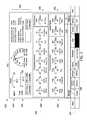
- FIG. 4is an illustration of a test selection screen 402 of a CFD 400 shown on the display screen 206 of the engine control system 200 .
- the test selection screen 402may be accessed by the operator by selecting the tests key 238 (shown in FIG. 2 ) on the operation menu 234 of the CFD 230 ( FIG. 2 ).
- the controller 202may adjust the indicator region 232 to include the test selection screen 402 .
- the controller 202may replace the windows 254 - 260 with the test selection screen 402 .
- the controller 202controls the information that is presented by the display screen 206 .
- the windows and bars described hereinmay present information that is stored on one or more databases in the memory 212 and retrieved by the controller 202 .
- the test selection screen 402may include a title bar 404 and at least one display window.
- the title bar 404indicates a generic description of the information illustrated in the test selection screen 402 of the CFD 400 shown on the display screen 206 .
- the title bar 404may include textual, numerical, and/or graphical information that indicates that the test selection screen 402 is being displayed on the CFD 400 and/or the display screen 206 .
- the title bar 404states “Tests” in the illustrated embodiment.
- the illustrated embodimentincludes two display windows 406 , 408 in the test selection screen 402 .
- a test window 406displays a first list 410 of multiple tests that the engine control system 202 may be configured to perform on one or more of the engine components 208 .
- the multiple tests in the first list 410may be interrelated within a common test category.
- a category window 408 adjacent to the test window 406displays a second list 412 that represents multiple test categories.
- the multiple tests displayed at a given time in the test window 406may be tests that are grouped within one of the test categories listed in the category window 408 . For example, the operator may navigate the CFD 400 to select a specific test by first selecting one of the test categories in the category window 408 .
- the test window 406Prior to selecting one of the test categories in the category window 408 , the test window 406 optionally may be blank or may display the tests that are affiliated with a previously selected or default test category.
- the test categoriesinclude engine speed tests 414 , turbo speed tests 416 , standby pump tests 418 , input/output tests 420 , and system tests 422 .
- the operatormay select one of the test categories using the input device 204 , such as by interacting with navigational keys 430 on the operation menu 234 to highlight a desired one of the test categories.
- the controller 202updates or adjusts the test window 406 to display the one or more tests affiliated with the selected category.
- the turbo speed tests category 416is selected (as indicated by the text “turbo speed tests” being highlighted by a box 432 ), and the test window 406 displays three tests within the turbo speed tests category 416 .
- the testsinclude left low pressure turbine over-speed test 424 , right low pressure turbine over-speed test 426 , and high pressure turbine over-speed test 428 .
- the left low pressure turbine over-speed test 424is highlighted by box 434 . It is noted that the specific tests, test categories, and numbers of tests and test categories shown in the illustrated embodiment are merely examples. The number of tests that are affiliated with a corresponding test category may number more or less than three in other embodiments and/or for other test categories.
- the controller 202may control the display screen 206 to display the category window 408 and the test window 406 sequentially or consecutively, such that the category window 408 is displayed first, and then the test window 406 is displayed while the category window 408 is no longer displayed.
- the CFD 400further includes a message bar 436 that is located between the test selection screen 402 and the operation menu 234 .
- the message bar 436provides a textual and/or numerical message to the operator. The message corresponds to the current information presented in the indicator region 232 .
- the message in the message bar 436may provide instructions to an operator, status updates, descriptions of alerts, and/or the like. In the illustrated embodiment, the message bar 436 provides instructions for an operator to “Please select test category and test to be executed.”
- the indication of a selected testis made by an operator using the input device 204 to select one of the tests in the test window 406 (shown in FIG. 4 ). For example, in the CFD 400 , once a given test is highlighted by the box 434 , that test may be selected by actuating a “Select Test” key 438 (referred to herein as “select test key” 438 ) of the operation menu 234 .
- the input device 204transmits an electrical signal to the controller 202 when such a selection is made.
- flow of the method 300returns to 302 , such that the display screen 206 continues to show the test selection screen 402 .
- the controller 202may switch the display screen 206 back to displaying the home screen shown in FIG. 2 .
- test detailsinclude pre-conditions or pre-requisites that are necessary in order to perform the selected test.
- the controller 202is programmed or configured to not perform the selected test until all of the pre-conditions for the selected test are satisfied.
- the pre-conditionsmay be associated with operating parameters of one or more of the engine components 208 .
- the pre-conditionsmay include an on/off status, an operating speed, a power consumption level, a communication quality status, and/or a threshold setting of one or more engine components 208 that are relevant to the selected test.
- the engine components 208 that are relevant to a selected testare the engine components 208 that are adjusted and/or manipulated by the controller 202 and/or are monitored by the sensors 222 during the performance of the selected test.
- the test detailsmay include additional information besides the pre-conditions, such as projected activity of one or more engine components 208 and the alarm device 216 (shown in FIG. 1 ) that is expected to occur during the performance of the selected test.
- the projected activitymay include adjustments that are to be made to the one or more engine components 208 , such as increasing an operating speed of a turbine or turbocharger.
- the projected activitymay also include expected alerts that may be triggered in response to the operating parameters of the engine component 208 exceeding one or more designated thresholds.
- operating parameters of one or more engine components 208 relevant to the selected testare received by the controller 202 from the one or more sensors 222 .
- the operating parametersare measured by the sensors 222 and received from the sensors 222 in the form of electrical data measurement signals.
- the measured operating parametersrepresent current operations of the engine components 208 , and may be updated periodically as the controller 202 receives updated data measurement signals from the sensors 222 .
- the measured operating parametersare displayed on a CFD of the display screen 206 .
- the display screen 206may display measured operating parameters of one or more of the engine components 208 in real-time.
- the measured operating parametersmay be used by the controller 202 to determine whether the pre-conditions for performing the selected test are satisfied.
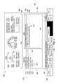
- FIG. 5illustrates test details on a CFD 500 shown on the display screen 206 of the engine control system 200 in a test detail screen 502 .
- the test detail screen 502may be accessed by the operator when the select test key 438 (shown in FIG. 4 ) is selected by the operator after one of the tests in the test window 406 is highlighted. For example, pressing the select test key 438 when the left low pressure turbine over-speed test 424 is highlighted causes the controller 202 to replace the test selection screen 402 with the test detail screen 502 .
- the test detail screen 502includes the title bar 404 , a sub-title bar 504 , an operating parameter window 506 , and a test detail window 508 .
- the title bar 404is unchanged from the CFD 400 , and still states “Tests.”
- the sub-title bar 504identifies the selected test that has been selected by the operator from the test selection screen 402 , which in the illustrated embodiment is the “Left Low Pressure Turbine Over-Speed Test.”
- the operating parameter window 506is disposed between the sub-title bar 504 and the test detail window 508 , although the location of the windows 506 , 508 and the bars 404 , 504 on the display screen 206 may be rearranged by the operator using the input device 204 .
- the measured operating parameters of one or more engine components 208 that are received by the controller 202 from the sensors 222are presented in the operating parameter window 506 of the CFD 500 .
- the controller 202may filter the received operating parameters to only display the operating parameters of engine components 208 that are relevant to the selected test.
- the selected testis a left turbine over-speed test
- the operating parameters displayed in the window 506correspond to relevant engine components 208 , such as a left turbocharger (that includes the turbine) and an engine of the power-generating system.
- the parameter window 506is organized in multiple cells 510 , and each cell 510 provides different information.
- each cell 510includes a parameter title 512 and a parameter value 514 that is measured or recorded by an applicable sensor 222 .
- one cell 510 Aindicates that the current operating speed of the low power left turbocharger is 28,510 rpm.
- test detail window 508The test details specific to the selected test are presented in the test detail window 508 .
- the test detail informationmay be retrieved by the controller 202 from the memory 212 .
- the test detail window 508is a text box that presents both the pre-conditions for the selected test and the projected activity during the selected test in a textual format.
- the pre-conditions or pre-requisites for the left low pressure turbine over-speed testrequire that the engine be running, the communication quality status between the engine control system 202 and the engine components 208 be good or “Healthy,” the engine power be less than 10%, and the turbocharger over-speed permissive be set to “High.”
- the information presented as projected activity during the teststates that when “Start Test” is pressed, turbine over-speed alarms for level one and level two thresholds will be logged after system set persistence time limits.
- the pre-requisites and projected activitymay be separated into two different windows or cells instead of being displayed together in the same test detail window 508 .
- the CFD 500shows that both the test details and the operating conditions are presented concurrently on the display screen 206 .
- concurrentlythere is a period of time in which both the test details and the operating conditions are displayed on the display screen 206 , even though one of the test details and the operating conditions may be displayed on the display screen 206 before the other is displayed or one may continue to be displayed after the other is no longer displayed.
- operatoris able to visually see how the operating conditions compare to the pre-requisites.
- one of the pre-conditionsis for the engine to be running, and the cell 510 B in the parameter window 506 indicates that the engine is indeed running.
- the controller 202is programmed to analyze the operating parameters to determine if the pre-conditions are satisfied.
- the controller 202may provide an alert indication on the CFD 500 designed to notify the operator. For example, since one of the illustrated pre-conditions is that the engine power is less than 10%, if the operating parameters indicate that the engine power is currently greater than 10%, the controller 202 determines that the pre-condition is not satisfied. In response, the controller 202 may provide indicia on the CFD 500 , such as by highlighting the cell 510 C that displays the current engine power parameter, controlling the cell 510 C or the text therein to flash, or displaying a warning symbol in the cell 510 C.
- the operation menu 234 on the CFD 500includes a start test key 516 .
- the start test key 516is selected by the operator in order to command the engine control system 200 to commence the selected test.
- An alternative or additional way that the controller 202 may indicate that the pre-conditions are not satisfiedis by disabling or removing the start test key 516 . Thus, the operator would not be able to select the start test key 516 .
- the controller 202may only enable or display the start test key 516 once the pre-conditions are satisfied.
- the indication of the selected testis made by an operator using the input device 204 to select the start test key 516 (shown in FIG. 5 ). If an indication to start the selected test has not been received, flow of the method 300 returns to 308 and the controller 202 receives updated operating parameters of the one or more engine components 208 from the sensors 222 . If, on the other hand, an indication to start the selected test has been received, flow continues to 314 and a determination is made whether the pre-conditions have been met. For example, the controller 202 may be programmed to only run a selected test when all of the pre-conditions are satisfied.
- controller 202determines that all of the pre-conditions are satisfied by the measured operating parameters, then flow of the method 300 proceeds to 318 and the selected test of the one or more engine components 208 is performed by the controller 202 . On the other hand, if not all of the pre-conditions are satisfied, then flow continues to 316 and the operator is notified.
- the controller 202notifies the operator that the received command to start the selected test will not be followed because not all of the pre-conditions for running the test are satisfied.
- the controller 202may notify the operator by controlling the alarm device 216 to provide a visual, audible, and/or vibrational alert.
- a message bar(e.g., the message bar 436 shown in FIG. 4 ) on the display screen 206 may display a text-based message to the operator informing the operator of the issue.
- the controller 202may be programmed to indicate to the operator which of the pre-conditions is not satisfied, such as by providing indicia in the test detail window 508 associated with the one or more pre-conditions that are not satisfied, providing indicia in the one or more cells 510 of the operating parameters that are deficient, identifying the unsatisfied pre-conditions in the message bar 436 , and/or the like.
- the operatormay be able to address the issues in an efficient manner.
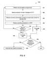
- FIG. 6is a flowchart of a method 350 for displaying test details during performance of a test of one or more engine components 208 of the power-generating system.
- the method 350may be related to the method 300 shown in FIG. 3 .
- the method 350may be a continuance of the method 300 .
- the test of one or more engine components 208is started.
- the testmay be performed by the controller 202 adjusting operational settings of one or more engine components 208 to test how the engine components 208 , the engine control system 200 , and the power-generating system respond to the adjusted settings.
- the controller 202may adjust the settings of the engine components 208 according to instructions stored in a test plan of the selected test.
- the test plan for each testmay be stored in a database in the memory 212 .
- the test planmay provide instructions for the controller 202 that outlines which engine components 208 to manipulate and how to adjust the operational settings of those components 208 .
- the test planmay call for the controller 202 to increase the operational speed of the left turbocharger gradually over time until the speed reaches one or more designated speeds.
- a first designated speedmay exceed a first threshold level
- a second designated speedmay exceed a second threshold level.
- the testmay be used to determine whether the safety and warning systems in place in the power-generating system are working properly, as various warnings and/or alerts are designed to be activated upon the turbocharger exceeding each of the threshold levels.
- a progress indicator messageis displayed on the CFD on the display screen 206 .
- the progress indicator messagemay provide a status of the test.
- the statusmay indicate current activity that is taking place during the performance of the test, a current stage of the test, and/or a current test that is being performed in a sequence of multiple tests.
- the current activity described in the progress indicator messagemay include information about the one or more engine components 208 that are being adjusted, such as to state, for example, how that the operating speed of the left turbocharger is being increased to the first threshold level.
- the current actionalso may include information about warnings and/or alerts, such as to identify the reason for a current audible and/or visible alarm.
- FIG. 7illustrates a CFD 700 shown on the display screen 206 of the engine control system 200 during performance of a selected test.
- the information presented in the test detail window 508is the same as on the CFD 500 shown in FIG. 5 . Since the left low pressure turbine over-speed test has started, the value of the operating parameter “Left Turbo Over-Speed Test Command” in cell 510 D has switched from 0 to 1.
- the progress indicator messageis displayed in the message bar 436 .
- the current progress indicator message in the CFD 700states that the left low pressure turbo over-speed test has been initiated.
- the controller 202may revise the progress indicator message periodically as the test progresses.
- operating parameters of one or more engine components 208 that are relevant to the test being performedare received from the sensors 222 .
- the operating parameters that are relevant to the testare displayed on the CFD 700 in the operating parameter window 506 .
- the steps 354 and 356are similar to the steps 308 and 310 , respectively, in the method 300 shown in FIG. 3 , so the steps 354 and 356 will not be described in detail again.
- the operating parameters of the engine components 208may be continually monitored and updated on the display screen 206 both prior to and during performance of a test.
- the operatormay command the engine control system 200 to end the test prematurely by selecting an abort test key 702 in the operation menu 234 , as shown on the CFD 700 in FIG. 7 , using the input device 204 . If such an indication has been received, the flow of the method 350 may proceed to 360 and the controller 202 may terminate the test. If such an indication has not been received, flow may return to 351 and the test may continue running as planned. If no indication to end the test has been received before the full performance of the test, then flow of the method 350 continues to 362 from the 356 . At 362 , the test is completed.
- FIG. 8illustrates a CFD 800 shown on the display screen 206 of the engine control system 200 at or near the end of a selected test.
- the cell 510 Eshows that the settings mandate that an “Alarm” is triggered in response to the operating speed of the left turbocharger exceeding a first threshold level (“L 1 ”), and adjacent cell 510 F mandates that the engine be “Shutdown” in response to the speed of the left turbocharger exceeding a second threshold level (“L 2 ”).
- the message bar 436 on the CFD 800states that the engine has been shut down due to the left low pressure turbocharger exceeding the second over-speed threshold L 2 .
- the message bar 436is highlighted in a box 802 in order to draw the operator's attention.
- the engine control system 200may activate various alerts, such as audible sounds, visible flashing lights, etc., in response to the turbocharger exceeding the over-speed threshold L 2 .
- the message bar 436informs the operator the reason for the alerts, and also provides the current status of the engine as no longer running.
- the cell 510 B in the operating parameter window 506also indicates that the current engine status is in a shutdown mode.
- flow of the method 350proceeds to 364 .
- the indication to download test resultsmay be received from the operator using the input device 204 .
- the operatormay select a download data key 804 in the operation menu 234 of the CFD 800 to provide the indication to the controller 202 .
- the controller 202may present the download data key 804 on the CFD 800 after a test has ended, such as via pre-mature termination or completion.
- the test resultsmay include data parameters measured by the one or more sensors 222 during the test.
- the data parametersmay indicate how the engine control system 200 , including the controller 202 , alarm device 216 , and one or more engine components 208 reacted to the adjustments made during the test. If an indication to download the test results has been received, flow of the method 350 continues to 366 and the test results are downloaded for analysis.
- the test resultsmay be stored in a database in the memory 212 and/or may be communicated remotely using the communication circuit 210 . Furthermore, the test results may be displayed by the controller 202 on the display screen 206 and/or printed onto a hard copy in order to be viewable for the operator. If no indication to download test results is received for a designated period of time, the method 350 ends.
- FIG. 9illustrates test details on a CFD 900 shown on the display screen 206 of the engine control system 200 according to an alternative embodiment.
- the CFD 900may be an alternative to the CFD 500 shown in FIG. 5 .
- the CFD 900is shown on the display screen 206 after a test has been selected form a list, but prior to starting the selected test.
- the test detail screen 502is rearranged such to include the operating parameter window 506 side-by-side laterally with the test detail window 508 in a split-screen format.
- the cells 902provide the pre-conditions that are necessary prior to running the selected test.
- Each cell 902corresponds to one of the cells 510 in the operating parameter window 506 , so the operator can visually compare the current operating parameters to the corresponding pre-conditions.
- the controller 202optionally may emphasize any pre-conditions that are currently unsatisfied by providing a visual indication, such as by highlighting the corresponding cells 902 , providing a different color font in the cells 902 , and/or flashing the cells 902 .
- the test detail window 502may include a separate window below the test detail window 508 and the operating parameter window 506 that describes projected activity that is to occur during the performance of the selected test.
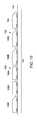
- FIG. 10illustrates one embodiment of a vehicle system 102 , in accordance with an embodiment.
- the engine control system 200may be implemented on the vehicle system 102 .
- the engine control system 200may control a propulsion-generating system on the vehicle system 102 , including traction motors, brakes, and the like.
- the engine control system 200is not limited to be implemented on the illustrated vehicle system 102 .
- the illustrated vehicle system 102includes propulsion-generating vehicles 104 , 106 (e.g., vehicles 104 , 106 A, 106 B, 106 C) and non-propulsion-generating vehicles 108 (e.g., vehicles 108 A, 108 B) that travel together along a route 110 .
- propulsion-generating vehicles 104 , 106e.g., vehicles 104 , 106 A, 106 B, 106 C
- non-propulsion-generating vehicles 108e.g., vehicles 108 A, 108 B
- the vehicles 104 , 106 , 108are shown as being mechanically coupled with each other, optionally, the vehicles 104 , 106 , 108 may not be mechanically coupled with each other.
- the propulsion-generating vehicles 104 , 106are shown as locomotives, the non-propulsion-generating vehicles 108 are shown as rail cars, and the vehicle system 102 is shown as a train in the illustrated embodiment.
- the number and arrangement of the vehicles 104 , 106 , 108 in the vehicle system 102are provided as one example and are not intended as limitations on all embodiments of the subject matter described herein.
- groups of one or more adjacent or neighboring propulsion-generating vehicles 104 and/or 106may be referred to as a vehicle consist.
- the vehicles 104 , 106 A, 106 Bmay be referred to as a first vehicle consist of the vehicle system 102 and the vehicle 106 C referred to as a second vehicle consist of the vehicle system 102 .
- the propulsion-generating vehicles 104 , 106may be arranged in a distributed power (DP) arrangement.
- the propulsion-generating vehicles 104 , 106can include a lead vehicle 104 that issues command messages to the other propulsion-generating vehicles 106 A, 106 B, 106 C which are referred to herein as remote vehicles.
- the designations “lead” and “remote”are not intended to denote spatial locations of the propulsion-generating vehicles 104 , 106 in the vehicle system 102 , but instead are used to indicate which propulsion-generating vehicle 104 , 106 is communicating (e.g., transmitting, broadcasting, or a combination of transmitting and broadcasting) command messages and which propulsion-generating vehicles 104 , 106 are being remotely controlled using the command messages.
- the lead vehicle 104may or may not be disposed at the front end of the vehicle system 102 (e.g., along a direction of travel of the vehicle system 102 ).
- the remote vehicles 106 A-Cneed not be separated from the lead vehicle 104 .
- a remote vehicle 106 A-Cmay be directly coupled with the lead vehicle 104 or may be separated from the lead vehicle 104 by one or more other remote vehicles 106 A-C and/or non-propulsion-generating vehicles 108 .
- a systeme.g., an engine control system
- the one or more sensorsare configured to monitor operating parameters of one or more engine components.
- the controllerhas one or more processors.
- the controlleris operatively connected to the one or more sensors and the one or more engine components.
- the controlleris programmed to perform operations in response to instructions stored on a non-transitory memory.
- the operationsinclude displaying test details on a display screen.
- the test detailsare specific to a selected test for the controller to perform on the one or more engine components.
- the test detailsinclude pre-conditional parameters of the one or more engine components that are necessary prior to starting the selected test.
- the operationsalso include receiving the monitored operating parameters of the one or more engine components from the one or more sensors, and determining whether the monitored operating parameters satisfy the pre-conditional parameters.
- the operationsfurther include, responsive to both receiving an indication to start the selected test and determining that the measured operating parameters satisfy the pre-conditional parameters, performing the selected test on the one or more engine components.
- the controlleris programmed to provide at least one of a visual or an audible alert for an operator responsive to receiving the indication to start the selected test when the monitored operating parameters do not satisfy the pre-conditional parameters.
- the controlleris programmed to not perform the selected test until all of the pre-conditional parameters are satisfied.
- the controllerin response to determining that at least one of the pre-conditional parameters are not satisfied by the monitored operating parameters, the controller is programmed to provide a visual alert on the display screen that indicates the at least one pre-conditional parameter that is not satisfied.
- the systemfurther includes an input device configured to receive selections from an operator.
- the controlleris programmed to receive the indication to start the selected test from the input device.
- the controlleris further programmed to display a list of multiple tests on the display screen prior to displaying the test details.
- the selected testis one of the tests in the list.
- the controlleris configured to display the test details of the selected test responsive to receiving an indication of the selected test by an operator using an input device.
- test detailsinclude the pre-conditional parameters and projected activity of the one or more engine components that is expected to occur during performance of the selected test.
- the systemfurther includes the display screen.
- the controller and the display screenare disposed in a housing of a device.
- the controlleris further programmed to display the monitored operating parameters of the one or more engine components on the display screen.
- the monitored operating parametersare displayed concurrently with the pre-conditional parameters of the selected test prior to performing the selected test.
- test detailsare presented on a computational functional display on the display screen.
- the one or more engine componentsinclude one or more of a pump, a turbocharger, a motor, an engine, a generator, or a radiator.
- a method(e.g., for testing an engine) that includes displaying test details on a display screen.
- the test detailsare specific to a selected test for performance on one or more engine components.
- the test detailsinclude pre-conditional parameters of the one or more engine components that are necessary prior to starting the selected test.
- the methodalso includes receiving monitored operating parameters of the one or more engine components from one or more sensors, and determining, using one or more processors, whether the monitored operating parameters satisfy the pre-conditional parameters.
- the methodfurther includes, responsive to both receiving an indication to start the selected test and determining that the monitored operating parameters satisfy the pre-conditional parameters, performing the selected test on the one or more engine components.
- the methodfurther includes displaying a list of multiple tests on the display screen prior to displaying the test details.
- the selected testis one of the tests in the list.
- the methodfurther includes receiving an indication of the selected test from the list by an operator using an input device and then displaying the test details for the selected test in response to the received indication.
- the list of multiple testsis a first list displayed in a test window on the display screen. The first list represents individual tests within a common test category.
- the methodfurther includes displaying a second list in a category window on the display screen. The second list represents multiple test categories.
- the methodfurther includes, during performance of the selected test, displaying a progress indicator message on the display screen.
- the progress indicator messagedescribes at least one of a current stage of the test or current activity of the one or more engine components.
- the methodfurther includes providing at least one of a visual or an audible alert for an operator responsive to receiving the indication to start the selected test when the measured operating parameters do not satisfy the pre-conditional parameters.
- the selected testis not performed until all of the pre-conditional parameters are satisfied.
- test detailsare presented on a computational functional display on the display screen.
- performing the selected testincludes adjusting operational settings of the one or more engine components according to instructions stored in a test plan of the selected test.
- a tangible and non-transitory computer readable mediumincludes one or more computer software modules configured to direct one or more processors to display test details on a display screen.
- the test detailsare specific to a selected test for performance on one or more engine components.
- the test detailsinclude pre-conditional parameters of the one or more engine components that are necessary prior to starting the selected test.
- the one or more computer software modulesare also configured to direct one or more processors to receive monitored operating parameters of the one or more engine components from one or more sensors, and to determine whether the measured operating parameters satisfy the pre-conditional parameters.
- the one or more computer software modulesare further configured to direct one or more processors to perform the selected test on the one or more engine components responsive to both receiving an indication to start the selected test and determining that the measured operating parameters satisfy the pre-conditional parameters.
- the one or more processorsare further directed to provide at least one of a visual or an audible alert for an operator responsive to receiving the indication to start the selected test when the monitored operating parameters do not satisfy the pre-conditional parameters.
- the pre-conditional parametersinclude one or more of an on/off status, an operating speed, a power consumption level, a communication quality status, or a threshold setting of the one or more engine components.
- the terms “software” and “firmware”are interchangeable, and include any computer program stored in memory for execution by a computer, including RAM memory, ROM memory, EPROM memory, EEPROM memory, and non-volatile RAM (NVRAM) memory.
- RAM memoryrandom access memory
- ROM memoryread-only memory
- EPROM memoryerasable programmable read-only memory
- EEPROM memoryelectrically erasable programmable read-only memory
- NVRAMnon-volatile RAM
- the functional blocksare not necessarily indicative of the division between hardware circuitry.
- one or more of the functional blocksmay be implemented in a single piece of hardware (for example, a general purpose signal processor, microcontroller, random access memory, hard disk, or the like).
- the programsmay be stand alone programs, may be incorporated as subroutines in an operating system, may be functions in an installed software package, or the like.
- the various embodimentsare not limited to the arrangements and instrumentality shown in the drawings.
Landscapes
- Engineering & Computer Science (AREA)
- Chemical & Material Sciences (AREA)
- Combustion & Propulsion (AREA)
- Mechanical Engineering (AREA)
- General Engineering & Computer Science (AREA)
- Computer Hardware Design (AREA)
- Microelectronics & Electronic Packaging (AREA)
- Physics & Mathematics (AREA)
- General Physics & Mathematics (AREA)
- Testing And Monitoring For Control Systems (AREA)
- Combined Controls Of Internal Combustion Engines (AREA)
Abstract
Description
Claims (20)
Priority Applications (1)
| Application Number | Priority Date | Filing Date | Title |
|---|---|---|---|
| US15/072,455US10495014B2 (en) | 2011-12-29 | 2016-03-17 | Systems and methods for displaying test details of an engine control test |
Applications Claiming Priority (3)
| Application Number | Priority Date | Filing Date | Title |
|---|---|---|---|
| US201161581425P | 2011-12-29 | 2011-12-29 | |
| US13/723,630US20130173137A1 (en) | 2011-12-29 | 2012-12-21 | System, apparatus, and method for protecting vehicle engines |
| US15/072,455US10495014B2 (en) | 2011-12-29 | 2016-03-17 | Systems and methods for displaying test details of an engine control test |
Related Parent Applications (1)
| Application Number | Title | Priority Date | Filing Date |
|---|---|---|---|
| US13/723,630Continuation-In-PartUS20130173137A1 (en) | 2011-12-29 | 2012-12-21 | System, apparatus, and method for protecting vehicle engines |
Publications (2)
| Publication Number | Publication Date |
|---|---|
| US20160201591A1 US20160201591A1 (en) | 2016-07-14 |
| US10495014B2true US10495014B2 (en) | 2019-12-03 |
Family
ID=56367215
Family Applications (1)
| Application Number | Title | Priority Date | Filing Date |
|---|---|---|---|
| US15/072,455Expired - Fee RelatedUS10495014B2 (en) | 2011-12-29 | 2016-03-17 | Systems and methods for displaying test details of an engine control test |
Country Status (1)
| Country | Link |
|---|---|
| US (1) | US10495014B2 (en) |
Families Citing this family (2)
| Publication number | Priority date | Publication date | Assignee | Title |
|---|---|---|---|---|
| CN106791824B (en)* | 2016-11-29 | 2019-05-31 | 深圳Tcl数字技术有限公司 | Select test screen method and device |
| JP7398420B2 (en)* | 2021-11-12 | 2023-12-14 | Thk株式会社 | Monitoring system |
Citations (173)
| Publication number | Priority date | Publication date | Assignee | Title |
|---|---|---|---|---|
| US1579281A (en) | 1924-06-06 | 1926-04-06 | Coughlin George Edwin | Vehicle spring seat |
| US3629801A (en) | 1969-08-28 | 1971-12-21 | Texas Instruments Inc | Seismic exploration in the vicinity of a shore area |
| US3893108A (en) | 1973-12-20 | 1975-07-01 | Texas Instruments Inc | Internal combustion engine protection circuit |
| US4019489A (en) | 1974-12-09 | 1977-04-26 | George Bowen Cartmill | Safety apparatus for engines |
| US4122720A (en) | 1977-04-07 | 1978-10-31 | Alnor Instrument Company | Diesel engine exhaust temperature monitor |
| US4136286A (en) | 1977-07-05 | 1979-01-23 | Woodward Governor Company | Isolated electrical power generation system with multiple isochronous, load-sharing engine-generator units |
| US4296409A (en) | 1979-03-12 | 1981-10-20 | Dickey-John Corporation | Combine performance monitor |
| US4399513A (en) | 1980-10-08 | 1983-08-16 | Ird Mechanalysis, Inc. | Machine monitoring system and apparatus |
| US4429670A (en) | 1978-02-03 | 1984-02-07 | Ulanet George D | Engine protection systems |
| US4467323A (en)* | 1981-12-04 | 1984-08-21 | Bear Automotive Service Equipment Company | Engine analyzer with simulated analog meter display |
| US4603394A (en) | 1984-07-30 | 1986-07-29 | Westinghouse Electric Corp. | Microprocessor-based extraction turbine control |
| US4653445A (en) | 1986-03-25 | 1987-03-31 | Book Anton M | Engine protection system |
| US4843575A (en) | 1982-10-21 | 1989-06-27 | Crane Harold E | Interactive dynamic real-time management system |
| US4861291A (en) | 1986-09-10 | 1989-08-29 | Sanshin Kogyo Kabushiki Kaisha | Marine engine protection device |
| US4924418A (en) | 1988-02-10 | 1990-05-08 | Dickey-John Corporation | Universal monitor |
| US4926331A (en) | 1986-02-25 | 1990-05-15 | Navistar International Transportation Corp. | Truck operation monitoring system |
| US5043727A (en) | 1989-02-03 | 1991-08-27 | Sanshin Kogyo Kabushiki Kaisha | Display system for marine vessel |
| US5070832A (en) | 1991-03-29 | 1991-12-10 | Cummins Engine Company, Inc. | Engine protection system |
| US5374917A (en) | 1992-09-16 | 1994-12-20 | Caterpillar Inc. | Computerized monitoring system having a programmable gauge |
| US5428555A (en) | 1993-04-20 | 1995-06-27 | Praxair, Inc. | Facility and gas management system |
| US5446665A (en) | 1993-03-18 | 1995-08-29 | John B. Adrain | Automotive multiple memory selector apparatus |
| CN1109138A (en) | 1993-11-22 | 1995-09-27 | 罗伯特-博希股份公司 | Internal combustion engine control method and device |
| US5523948A (en) | 1990-09-06 | 1996-06-04 | Adrain; John B. | Apparatus and method for modifying control of an originally manufactured engine control module |
| US5803043A (en) | 1996-05-29 | 1998-09-08 | Bayron; Harry | Data input interface for power and speed controller |
| US5828977A (en) | 1995-07-31 | 1998-10-27 | Nippondenso Co., Ltd. | Program/data overwriting control after machine stop |
| US5884210A (en) | 1996-08-27 | 1999-03-16 | Caterpillar Inc. | Programmable engine parameter verification apparatus and method of operating same |
| US6067489A (en) | 1997-06-04 | 2000-05-23 | Detroit Diesel Corporation | Method for engine control |
| US6131539A (en) | 1999-06-30 | 2000-10-17 | Detroit Diesel Corporation | System and method for enhanced engine monitoring and protection |
| US6141628A (en) | 1997-06-10 | 2000-10-31 | Amot Controls Corporation | Programmable logic controller software with embedded class logic and alarm/shutdown functionality |
| US6169953B1 (en) | 1997-09-08 | 2001-01-02 | Case Corporation | Method and apparatus for protecting an engine from overheating |
| US6172428B1 (en)* | 1998-12-30 | 2001-01-09 | Westwood Corporation | Digital control system and method for generator sets |
| US6192321B1 (en)* | 1997-09-29 | 2001-02-20 | Fisher Controls International, Inc. | Method of and apparatus for deterministically obtaining measurements |
| US6259981B1 (en) | 1999-06-17 | 2001-07-10 | Thomas J. Wilcosky | Caution/warning system for displaying system malfunctions/faults in a night-time viewing mode |
| US6269300B1 (en) | 1995-03-29 | 2001-07-31 | Caterpillar Inc. | Method for producing production control software for a natural gas or diesel engine controller |
| US20010027070A1 (en) | 1999-12-22 | 2001-10-04 | Mike Morris | Method and system for tracking ship engine emmissions as a function of geographical location |
| US6304814B1 (en) | 1999-11-02 | 2001-10-16 | Autotronic Controls Corporation | User interface for electronic controller |
| US6351692B1 (en) | 2000-10-24 | 2002-02-26 | Kohler Co. | Method and apparatus for configuring a genset controller for operation with particular gensets |
| US20020069011A1 (en) | 2000-12-05 | 2002-06-06 | Detroit Diesel Corporaton | Method and system for enchanced engine control |
| US6421572B1 (en) | 1999-01-26 | 2002-07-16 | Keyence Corporation | Programmable controller for sequentially controlling controlled machine |
| US6441726B1 (en) | 2000-04-03 | 2002-08-27 | Delphi Technologies, Inc. | Configurable warning system for a vehicle instrument cluster |
| US6512974B2 (en) | 2000-02-18 | 2003-01-28 | Optimum Power Technology | Engine management system |
| US6525664B1 (en) | 1994-11-10 | 2003-02-25 | Michael J. Erland | Control console remote monitoring system |
| US6530359B1 (en) | 1998-09-04 | 2003-03-11 | Wacker Construction Equipment Ag | Generating unit with engine speed control device |
| US6535811B1 (en) | 1999-11-03 | 2003-03-18 | Holley Performance Products, Inc. | System and method for real-time electronic engine control |
| US6560528B1 (en) | 2000-03-24 | 2003-05-06 | Internal Combustion Technologies, Inc. | Programmable internal combustion engine controller |
| JP2003191772A (en) | 2001-12-27 | 2003-07-09 | Nippon Seiki Co Ltd | Display device |
| US6615160B1 (en)* | 1998-11-24 | 2003-09-02 | Bombardier Motor Corperation Of America | Methods and apparatus for engine diagnostics |
| US20030216856A1 (en)* | 2002-05-15 | 2003-11-20 | Jacobson Evan Earl | Diagnostic systems for turbocharged engines |
| US20040002810A1 (en)* | 2002-07-01 | 2004-01-01 | Syu Akuzawa | Malfunction diagnosis system for engine |
| US20040084014A1 (en) | 2002-11-06 | 2004-05-06 | Detroit Diesel Corporation | Method and apparatus for limiting engine operation in a programmable range |
| US20040107039A1 (en) | 2002-12-03 | 2004-06-03 | Greg Hasler | Air/fuel ratio control using a display interface |
| US6757606B1 (en) | 2003-06-02 | 2004-06-29 | Brunswick Corporation | Method for controlling the operation of an internal combustion engine |
| WO2004059411A1 (en) | 2002-12-30 | 2004-07-15 | Marine Cybernetics As | System and method for testing a control system of a marine vessel |
| US6782313B1 (en) | 1999-05-11 | 2004-08-24 | Robert Bosch Gmbh | Diagnostic test device for motor vehicle with programmable control devices |
| US6801849B2 (en)* | 2001-07-13 | 2004-10-05 | Bombardier Recreational Products Inc. | Engine diagnostic via PDA |
| US20040199324A1 (en)* | 2003-04-01 | 2004-10-07 | Xiaoqiu Li | System for diagnosing operation of a cooling system for an internal combustion engine |
| US20040205700A1 (en) | 2003-04-11 | 2004-10-14 | Leu Jenson H. | Apparatus and method for real-time caution and warning and system health management |
| US20040267438A1 (en)* | 2003-06-27 | 2004-12-30 | Boysen Dale R. | Method and apparatus for processing and display of diesel injection waveform |
| US20050042151A1 (en) | 2002-10-28 | 2005-02-24 | Alward Gordon S. | Nonwoven composites and related products and processes |
| US6928362B2 (en) | 2003-06-06 | 2005-08-09 | John Meaney | System and method for real time programmability of an engine control unit |
| WO2005077754A1 (en) | 2004-02-16 | 2005-08-25 | Marine Cybernetics As | Method and system for testing a control system of a marine vessel |
| US6941176B2 (en) | 2000-04-24 | 2005-09-06 | Yamaha Hatsudoki Kabushiki Kaisha | Method and apparatus for changing and controlling characteristics of device |
| US20050258948A1 (en)* | 2004-05-21 | 2005-11-24 | Bolander Thomas E | Single person vehicle light test |
| WO2005113126A1 (en) | 2004-04-28 | 2005-12-01 | Geo2 Technologies, Inc. | Nonwoven composites and related products and methods |
| US20060015244A1 (en) | 2002-10-10 | 2006-01-19 | Hawkins Jeffery S | Redundant engine shutdown system |
| US7047114B1 (en) | 2003-10-23 | 2006-05-16 | Charles David Rogers | System and apparatus for automatic and continuous monitoring, proactive warning and control of one or more independently operated vessels |
| US20060106510A1 (en) | 2004-11-01 | 2006-05-18 | Heffington Mark F | Programmable automotive computer system |
| US7051692B1 (en) | 2004-12-01 | 2006-05-30 | Brunswick Corporation | Starting system for a marine engine |
| US20060176193A1 (en) | 2005-01-24 | 2006-08-10 | Thomas G. Faria Corporation | Marine vessel monitoring and communications system and method |
| US7116216B2 (en) | 2004-07-22 | 2006-10-03 | Keith Andreasen | Serial data gauge |
| US7143363B1 (en) | 2002-07-25 | 2006-11-28 | Brunswick Corporation | Method for displaying marine vessel information for an operator |
| US20060288701A1 (en) | 2005-03-10 | 2006-12-28 | Detroit Diesel Corporation | System and method for backpressure compensation for controlling exhaust gas particulate emissions |
| US7182064B2 (en) | 2003-01-22 | 2007-02-27 | Mtu Friedrichshafen Gmbh | Method for regulating the rotational speed of an internal combustion engine |
| US7216052B2 (en)* | 2005-02-08 | 2007-05-08 | Spx Corporation | Authoring diagnostic test sequences apparatus and method |
| US20070162216A1 (en) | 2005-12-23 | 2007-07-12 | Choi Cathy Y | Simulation-based control for HCCI power systems |
| US7272483B2 (en) | 2005-07-26 | 2007-09-18 | Quadzilla Performance Technologies, Inc. | Vehicular power enhancement control system |
| US7330133B2 (en) | 2003-11-28 | 2008-02-12 | Yamaha Marine Kabushiki Kaisha | Engine condition indicating device for boat |
| US20080060598A1 (en) | 2006-09-07 | 2008-03-13 | Dobeck Michael V | Method and apparatus for modifying fuel injection scheme |
| WO2008031880A2 (en) | 2006-09-13 | 2008-03-20 | Marine & Remote Sensing Solutions (Marss) | Manoeuvre and safety system for a marine vessel |
| US7349794B2 (en) | 2003-09-03 | 2008-03-25 | Malone Specialty, Inc. | Engine protection system |
| US7361067B1 (en) | 2006-11-02 | 2008-04-22 | Brunswick Corporation | Method for controlling the acceleration of a marine vessel used for water skiing |
| US7441189B2 (en) | 2005-06-20 | 2008-10-21 | Navico International Limited | Instrumentation interface display customization |
| US20080269011A1 (en) | 2007-04-30 | 2008-10-30 | Caterpillar Inc. | System for controlling a machine with a continuously variable transmission |
| WO2008134251A2 (en) | 2007-04-27 | 2008-11-06 | Alcoa Inc. | Energy storage device |
| US20080312775A1 (en) | 2006-03-20 | 2008-12-18 | Ajith Kuttannair Kumar | System, method, and computer software code for optimizing speed regulation of a remotely controlled powered system |
| US7472684B1 (en) | 2007-11-14 | 2009-01-06 | Cnh America Llc | High low engine speed cruise control |
| US7490584B1 (en) | 2006-12-15 | 2009-02-17 | Brunswick Corporation | Fuel enrichment cold start/run circuit |
| US20090079399A1 (en) | 2007-09-25 | 2009-03-26 | Evgeni Ganev | Overload control of an electric power generation system |
| US20090156068A1 (en) | 2007-12-12 | 2009-06-18 | Foss Maritime Company | Hybrid propulsion systems |
| US20090187297A1 (en) | 2008-01-17 | 2009-07-23 | Loretta Kish | Integrated Vessel Monitoring and Control System |
| US20090184812A1 (en) | 2007-08-09 | 2009-07-23 | Michael Drew | User Configured Display System For Motor Vehicle |
| US20090186325A1 (en) | 2006-03-20 | 2009-07-23 | Ajith Kuttannair Kumar | System, Method, and Computer Software Code for Instructing an Operator to Control a Powered System Having an Autonomous Controller |
| US20090222155A1 (en) | 2008-02-15 | 2009-09-03 | Glacier Bay, Inc. | Propulsion system |
| WO2009109702A1 (en) | 2008-03-03 | 2009-09-11 | Wärtsilä Finland Oy | Speed controller for piston engine |
| US7593784B2 (en) | 2005-06-07 | 2009-09-22 | Rockwell Automation Technologies, Inc. | Machinery condition assessment module |
| US20090240391A1 (en) | 2008-02-08 | 2009-09-24 | Airmax Group Plc | Configuration of an Electronic Control System for Controlling the Operation of at Least One Component of a Vehicle |
| WO2009133399A2 (en) | 2008-04-30 | 2009-11-05 | Mobilizer Limited | A system for and method of degrading or analysing the performance of an internal combustion engine |
| US7643916B2 (en)* | 2006-06-14 | 2010-01-05 | Spx Corporation | Vehicle state tracking method and apparatus for diagnostic testing |
| US7693649B2 (en) | 2006-12-29 | 2010-04-06 | Detroit Diesel Corporation | Monitoring unit state chart and a debounce logic |
| US20100094490A1 (en) | 2007-04-19 | 2010-04-15 | Glacier Bay, Inc | Power generation system for marine vessel |
| US20100106350A1 (en) | 2008-10-28 | 2010-04-29 | Glacier Bay, Inc. | Real-time efficiency monitoring for marine vessel |
| US7715959B2 (en)* | 2002-06-21 | 2010-05-11 | Intel Corporation | PC-based automobile owner's manual, diagnostics, and auto care |
| US20100125383A1 (en) | 2008-11-14 | 2010-05-20 | Pierre Caouette | Electronic method of controlling propulsion and regeneration for electric, hybrid-electric and diesel-electric marine crafts, and an apparatus therefor |
| US20100131150A1 (en) | 2008-11-25 | 2010-05-27 | Caterpillar Inc. | Automatic shut down system for machine having engine and work implement |
| US7726279B2 (en) | 2006-04-21 | 2010-06-01 | Yamaha Hatsudoki Kabushiki Kaisha | Remote control system of an internal combustion engine for a boat |
| US20100204898A1 (en) | 2007-08-23 | 2010-08-12 | Adaptronic Electronics Pty Ltd | Engine control system |
| US7786851B2 (en) | 2007-08-09 | 2010-08-31 | Drew Technologies | Data acquisition and display system for motor vehicle |
| JP2010224893A (en) | 2009-03-24 | 2010-10-07 | Yamatake Corp | Monitoring device and monitoring method |
| US20110023822A1 (en) | 2009-07-31 | 2011-02-03 | Paul Spivak | Intelli-tach |
| JP2011080968A (en) | 2009-10-09 | 2011-04-21 | Oval Corp | Maintenance expert system in measuring device |
| US7980905B2 (en)* | 2007-11-25 | 2011-07-19 | C-Mar Holdings, Ltd. | Method and apparatus for providing power to a marine vessel |
| WO2011094582A1 (en) | 2010-02-01 | 2011-08-04 | Exxonmobil Research And Engineering Company | Method for improving the fuel efficiency of engine oil compositions for large low and medium speed engines by reducing the traction coefficient |
| US20110195884A1 (en) | 2010-02-01 | 2011-08-11 | Exxonmobil Research And Engineering Company | Method for improving the fuel efficiency of engine oil compositions for large low and medium speed engines by reducing the traction coefficient |
| US20110195882A1 (en) | 2010-02-01 | 2011-08-11 | Exxonmobil Research And Engineering Company | Method for improving the fuel efficiency of engine oil compositions for large low, medium and high speed engines by reducing the traction coefficient |
| US20110195618A1 (en) | 2010-02-08 | 2011-08-11 | Brunswick Corporation | Systems and Methods for Controlling Battery Performance in Hybrid Marine Propulsion Systems |
| US20110195878A1 (en) | 2010-02-01 | 2011-08-11 | Exxonmobil Research And Engineering Company | Method for improving the fuel efficiency of engine oil compositions for large low and medium speed engines by reducing the traction coefficient |
| US20110207639A1 (en) | 2010-02-01 | 2011-08-25 | Exxonmobil Research And Engineering Company | Method for improving the fuel efficiency of engine oil compositions for large low and medium speed engines by reducing the traction coefficient |
| US8160767B1 (en)* | 2006-06-08 | 2012-04-17 | Thompson Bernie C | Vehicle diagnostic tool—utilizing volumetric efficiency |
| USD681049S1 (en) | 2010-12-29 | 2013-04-30 | Karl Storz Gmbh & Co. Kg | Display screen with graphical user interface |
| USD681651S1 (en) | 2012-01-05 | 2013-05-07 | Flextronics Ap, Llc | Display panel with graphical user interface for analyzing and presenting supply, fabrication, and logistics data |
| USD681649S1 (en) | 2012-01-05 | 2013-05-07 | Flextronics Ap, Llc | Display panel with graphical user interface for analyzing and presenting supply, fabrication, and logistics data |
| USD684173S1 (en) | 2012-06-11 | 2013-06-11 | Microsoft Corporation | Display screen with graphical user interface |
| US20130171590A1 (en) | 2006-03-20 | 2013-07-04 | General Electric Company | System, method, and computer software code for instructing an operator to control a powered system having an autonomous controller |
| USD687838S1 (en) | 2010-07-30 | 2013-08-13 | General Electric Company | Display screen or portion thereof of an engine control system with graphical user interface |
| USD692912S1 (en) | 2011-10-26 | 2013-11-05 | Mcafee, Inc. | Computer having graphical user interface |
| US8620461B2 (en) | 2009-09-24 | 2013-12-31 | Honeywell International, Inc. | Method and system for updating tuning parameters of a controller |
| USD705242S1 (en) | 2012-05-11 | 2014-05-20 | Unitedhealth Group Incorporated | Display screen or portions thereof with graphical user interface |
| USD705798S1 (en) | 2011-09-30 | 2014-05-27 | Life Technologies Corporation | Display screen with graphical user interface |
| US20140152469A1 (en) | 2012-12-03 | 2014-06-05 | Continental Automotive Systems, Inc. | Vehicle speed advisor |
| USD709905S1 (en) | 2012-05-11 | 2014-07-29 | Unitedhealth Group Incorporated | Display screen or portions thereof with graphical user interface |
| USD710368S1 (en) | 2010-05-20 | 2014-08-05 | Cfph, Llc | Display screen of a computing device with graphical user interface |
| USD714339S1 (en) | 2010-12-03 | 2014-09-30 | Life Technologies Corporation | Display screen with graphical user interface of a cell counter |
| USD719963S1 (en) | 2012-02-07 | 2014-12-23 | Rowland Hobbs | Monitor display screen with a graphical user interface |
| USD720767S1 (en) | 2013-03-15 | 2015-01-06 | Adp, Llc | Display screen or portion thereof of a human capital management system with graphical user interface |
| USD723055S1 (en) | 2013-03-14 | 2015-02-24 | Microsoft Corporation | Display screen with graphical user interface |
| US20150149074A1 (en) | 2012-06-01 | 2015-05-28 | Abb Technology Ag | Method and system for determination of a route for a ship |
| USD753684S1 (en) | 2012-07-20 | 2016-04-12 | Siemens Aktiengesellschaft | Display screen with graphical user interface for a train operator control |
| USD754696S1 (en) | 2014-01-27 | 2016-04-26 | Nortek Security & Control Llc | Computer screen display panel with graphical user interface |
| US20160117657A1 (en) | 2014-10-22 | 2016-04-28 | Causam Energy, Inc. | Systems and Methods for Advanced Energy Settlements, Network-Based Messaging, and Applications Supporting the Same |
| US9342983B1 (en) | 2012-10-23 | 2016-05-17 | Greenroad Driving Technologies Ltd. | User interface for driver performance application |
| USD757762S1 (en) | 2013-04-05 | 2016-05-31 | Thales Avionics, Inc. | Display screen or portion thereof with graphical user interface |
| USD759059S1 (en) | 2014-09-11 | 2016-06-14 | Korean Airlines Co., Ltd. | Display screen with graphical user interface |
| USD759675S1 (en) | 2014-09-11 | 2016-06-21 | Korean Airlines Co., Ltd. | Display screen with animated graphical user interface |
| US20160203569A1 (en) | 2015-01-13 | 2016-07-14 | Causam Energy, Inc. | Systems and methods for advanced energy settlements, network-based messaging, and software applications for electric power grids, microgrids, grid elements, and/or electric power networks |
| USD765090S1 (en) | 2013-06-25 | 2016-08-30 | Tencent Technology (Shenzhen) Company Limited | Display screen or portion thereof with graphical user interface |
| USD766258S1 (en) | 2013-12-31 | 2016-09-13 | Beijing Qinhoo Technology Co. Ltd | Display screen with a graphical user interface |
| USD766264S1 (en) | 2014-11-19 | 2016-09-13 | Qcue, Inc. | Display screen with graphical user interface for presenting ticket pricing |
| USD766940S1 (en) | 2015-08-17 | 2016-09-20 | Td Ameritrade Ip Company, Inc. | Display screen or portion thereof with graphical user interface |
| USD766916S1 (en) | 2013-12-02 | 2016-09-20 | Symantec Corporation | Display screen with graphical user interface |
| USD769287S1 (en) | 2015-04-27 | 2016-10-18 | Vericle Corporation | Computer screen with practice health monitor and radar graphical user interface |
| USD771079S1 (en) | 2013-01-04 | 2016-11-08 | Level 3 Communications, Llc | Display screen or portion thereof with graphical user interface |
| USD772245S1 (en) | 2015-03-18 | 2016-11-22 | Google Inc. | Display screen or portion thereof with transitional graphical user interface |
| USD773532S1 (en) | 2015-08-31 | 2016-12-06 | University Of Malta | Display screen or portion thereof with animated graphical user interface |
| USD774521S1 (en) | 2012-11-08 | 2016-12-20 | Uber Technologies, Inc. | Display screen of a computing device with a computer-generated electronic panel for providing confirmation of a service request |
| USD775142S1 (en) | 2015-02-20 | 2016-12-27 | State Farm Mutual Automobile Insurance Company | Display screen with a graphical user interface for automobile repair estimation and recommendation |
| USD775635S1 (en) | 2014-11-07 | 2017-01-03 | Adp, Llc | Display screen or portion thereof with graphical user interface |
| USD776136S1 (en) | 2015-03-02 | 2017-01-10 | Envision Energy (Jiangsu) Co., Ltd. | Display screen with a downtime analyzer graphical user interface |
| USD777177S1 (en) | 2014-10-01 | 2017-01-24 | Western Digital Technologies, Inc. | Display screen or portion thereof with graphical user interface |
| USD778284S1 (en) | 2014-03-04 | 2017-02-07 | Kenall Manufacturing Company | Display screen with graphical user interface for a communication terminal |
| USD778300S1 (en) | 2015-05-21 | 2017-02-07 | Layer3 TV, Inc. | Display screen or portion thereof with a graphical user interface shown thereon |
| USD778935S1 (en) | 2015-03-27 | 2017-02-14 | Kruss GmbH, Wissenschaftliche Laborgerate | Display screen with transitional graphical user interface |
| USD780194S1 (en) | 2015-09-08 | 2017-02-28 | Citibank, N.A. | Display screen or portion thereof with a transitional graphical user interface of a financial data viewer application |
| USD780190S1 (en) | 2014-12-12 | 2017-02-28 | Wayblazer, Inc. | Display screen with graphical user interface |
| USD781303S1 (en) | 2014-11-25 | 2017-03-14 | General Electric Company | Display screen or portion thereof with graphical user interface |
| USD781308S1 (en) | 2015-11-03 | 2017-03-14 | Vertex Analytics, Inc. | Display screen with a graphical user interface |
| USD781304S1 (en) | 2014-11-26 | 2017-03-14 | General Electric Company | Display screen or portion thereof with graphical user interface |
| USD781307S1 (en) | 2015-11-03 | 2017-03-14 | Vertex Analytics, Inc. | Display screen with a transitional graphical user interface |
| USD783027S1 (en) | 2015-09-08 | 2017-04-04 | Citibank, N.A. | Display screen or portion thereof with a transitional graphical user interface of a trade viewer application |
| USD784377S1 (en) | 2014-12-12 | 2017-04-18 | Jpmorgan Chase Bank, N.A. | Display screen or portion thereof with a graphical user interface |
| USD785016S1 (en) | 2014-06-23 | 2017-04-25 | Deutsche Bank Ag | Display screen with graphical user interface |
| USD785021S1 (en) | 2013-03-29 | 2017-04-25 | Deere & Company | Display screen with an animated graphical user interface |
| USD786281S1 (en) | 2014-12-09 | 2017-05-09 | Jpmorgan Chase Bank, N.A. | Display screen or portion thereof with a graphical user interface |
| USD788792S1 (en) | 2015-10-28 | 2017-06-06 | Technogym S.P.A. | Portion of a display screen with a graphical user interface |
- 2016
- 2016-03-17USUS15/072,455patent/US10495014B2/ennot_activeExpired - Fee Related
Patent Citations (202)
| Publication number | Priority date | Publication date | Assignee | Title |
|---|---|---|---|---|
| US1579281A (en) | 1924-06-06 | 1926-04-06 | Coughlin George Edwin | Vehicle spring seat |
| US3629801A (en) | 1969-08-28 | 1971-12-21 | Texas Instruments Inc | Seismic exploration in the vicinity of a shore area |
| US3893108A (en) | 1973-12-20 | 1975-07-01 | Texas Instruments Inc | Internal combustion engine protection circuit |
| US4019489A (en) | 1974-12-09 | 1977-04-26 | George Bowen Cartmill | Safety apparatus for engines |
| US4122720A (en) | 1977-04-07 | 1978-10-31 | Alnor Instrument Company | Diesel engine exhaust temperature monitor |
| US4136286A (en) | 1977-07-05 | 1979-01-23 | Woodward Governor Company | Isolated electrical power generation system with multiple isochronous, load-sharing engine-generator units |
| US4429670A (en) | 1978-02-03 | 1984-02-07 | Ulanet George D | Engine protection systems |
| US4296409A (en) | 1979-03-12 | 1981-10-20 | Dickey-John Corporation | Combine performance monitor |
| US4399513A (en) | 1980-10-08 | 1983-08-16 | Ird Mechanalysis, Inc. | Machine monitoring system and apparatus |
| US4467323A (en)* | 1981-12-04 | 1984-08-21 | Bear Automotive Service Equipment Company | Engine analyzer with simulated analog meter display |
| US4843575A (en) | 1982-10-21 | 1989-06-27 | Crane Harold E | Interactive dynamic real-time management system |
| US4603394A (en) | 1984-07-30 | 1986-07-29 | Westinghouse Electric Corp. | Microprocessor-based extraction turbine control |
| US4926331A (en) | 1986-02-25 | 1990-05-15 | Navistar International Transportation Corp. | Truck operation monitoring system |
| US4653445A (en) | 1986-03-25 | 1987-03-31 | Book Anton M | Engine protection system |
| US4861291A (en) | 1986-09-10 | 1989-08-29 | Sanshin Kogyo Kabushiki Kaisha | Marine engine protection device |
| US4924418A (en) | 1988-02-10 | 1990-05-08 | Dickey-John Corporation | Universal monitor |
| US5043727A (en) | 1989-02-03 | 1991-08-27 | Sanshin Kogyo Kabushiki Kaisha | Display system for marine vessel |
| US5523948A (en) | 1990-09-06 | 1996-06-04 | Adrain; John B. | Apparatus and method for modifying control of an originally manufactured engine control module |
| US5070832A (en) | 1991-03-29 | 1991-12-10 | Cummins Engine Company, Inc. | Engine protection system |
| US5374917A (en) | 1992-09-16 | 1994-12-20 | Caterpillar Inc. | Computerized monitoring system having a programmable gauge |
| US5446665A (en) | 1993-03-18 | 1995-08-29 | John B. Adrain | Automotive multiple memory selector apparatus |
| US5428555A (en) | 1993-04-20 | 1995-06-27 | Praxair, Inc. | Facility and gas management system |
| CN1109138A (en) | 1993-11-22 | 1995-09-27 | 罗伯特-博希股份公司 | Internal combustion engine control method and device |
| US6525664B1 (en) | 1994-11-10 | 2003-02-25 | Michael J. Erland | Control console remote monitoring system |
| US6269300B1 (en) | 1995-03-29 | 2001-07-31 | Caterpillar Inc. | Method for producing production control software for a natural gas or diesel engine controller |
| US5828977A (en) | 1995-07-31 | 1998-10-27 | Nippondenso Co., Ltd. | Program/data overwriting control after machine stop |
| US5803043A (en) | 1996-05-29 | 1998-09-08 | Bayron; Harry | Data input interface for power and speed controller |
| US5884210A (en) | 1996-08-27 | 1999-03-16 | Caterpillar Inc. | Programmable engine parameter verification apparatus and method of operating same |
| US6067489A (en) | 1997-06-04 | 2000-05-23 | Detroit Diesel Corporation | Method for engine control |
| US6141628A (en) | 1997-06-10 | 2000-10-31 | Amot Controls Corporation | Programmable logic controller software with embedded class logic and alarm/shutdown functionality |
| US6169953B1 (en) | 1997-09-08 | 2001-01-02 | Case Corporation | Method and apparatus for protecting an engine from overheating |
| US6192321B1 (en)* | 1997-09-29 | 2001-02-20 | Fisher Controls International, Inc. | Method of and apparatus for deterministically obtaining measurements |
| US6530359B1 (en) | 1998-09-04 | 2003-03-11 | Wacker Construction Equipment Ag | Generating unit with engine speed control device |
| US20030182085A1 (en)* | 1998-11-24 | 2003-09-25 | Quinnett Wilbur V. | Methods and apparatus for engine diagnostics |
| US6615160B1 (en)* | 1998-11-24 | 2003-09-02 | Bombardier Motor Corperation Of America | Methods and apparatus for engine diagnostics |
| US6172428B1 (en)* | 1998-12-30 | 2001-01-09 | Westwood Corporation | Digital control system and method for generator sets |
| US6421572B1 (en) | 1999-01-26 | 2002-07-16 | Keyence Corporation | Programmable controller for sequentially controlling controlled machine |
| US6782313B1 (en) | 1999-05-11 | 2004-08-24 | Robert Bosch Gmbh | Diagnostic test device for motor vehicle with programmable control devices |
| US6259981B1 (en) | 1999-06-17 | 2001-07-10 | Thomas J. Wilcosky | Caution/warning system for displaying system malfunctions/faults in a night-time viewing mode |
| US6131539A (en) | 1999-06-30 | 2000-10-17 | Detroit Diesel Corporation | System and method for enhanced engine monitoring and protection |
| US6304814B1 (en) | 1999-11-02 | 2001-10-16 | Autotronic Controls Corporation | User interface for electronic controller |
| US6535811B1 (en) | 1999-11-03 | 2003-03-18 | Holley Performance Products, Inc. | System and method for real-time electronic engine control |
| US20010027070A1 (en) | 1999-12-22 | 2001-10-04 | Mike Morris | Method and system for tracking ship engine emmissions as a function of geographical location |
| US6512974B2 (en) | 2000-02-18 | 2003-01-28 | Optimum Power Technology | Engine management system |
| US6560528B1 (en) | 2000-03-24 | 2003-05-06 | Internal Combustion Technologies, Inc. | Programmable internal combustion engine controller |
| US6441726B1 (en) | 2000-04-03 | 2002-08-27 | Delphi Technologies, Inc. | Configurable warning system for a vehicle instrument cluster |
| US6941176B2 (en) | 2000-04-24 | 2005-09-06 | Yamaha Hatsudoki Kabushiki Kaisha | Method and apparatus for changing and controlling characteristics of device |
| US6351692B1 (en) | 2000-10-24 | 2002-02-26 | Kohler Co. | Method and apparatus for configuring a genset controller for operation with particular gensets |
| US20020069011A1 (en) | 2000-12-05 | 2002-06-06 | Detroit Diesel Corporaton | Method and system for enchanced engine control |
| US6801849B2 (en)* | 2001-07-13 | 2004-10-05 | Bombardier Recreational Products Inc. | Engine diagnostic via PDA |
| JP2003191772A (en) | 2001-12-27 | 2003-07-09 | Nippon Seiki Co Ltd | Display device |
| US20030216856A1 (en)* | 2002-05-15 | 2003-11-20 | Jacobson Evan Earl | Diagnostic systems for turbocharged engines |
| US7715959B2 (en)* | 2002-06-21 | 2010-05-11 | Intel Corporation | PC-based automobile owner's manual, diagnostics, and auto care |
| US20040002810A1 (en)* | 2002-07-01 | 2004-01-01 | Syu Akuzawa | Malfunction diagnosis system for engine |
| US7143363B1 (en) | 2002-07-25 | 2006-11-28 | Brunswick Corporation | Method for displaying marine vessel information for an operator |
| US20060015244A1 (en) | 2002-10-10 | 2006-01-19 | Hawkins Jeffery S | Redundant engine shutdown system |
| US20080171650A1 (en) | 2002-10-28 | 2008-07-17 | Alward Gordon S | Nonwoven Composites and Related Products and Methods |
| US7550117B2 (en) | 2002-10-28 | 2009-06-23 | Geo2 Technologies, Inc. | Nonwoven composites and related products and processes |
| US20050042151A1 (en) | 2002-10-28 | 2005-02-24 | Alward Gordon S. | Nonwoven composites and related products and processes |
| US7572416B2 (en) | 2002-10-28 | 2009-08-11 | Geo2 Technologies, Inc | Nonwoven composites and related products and methods |
| US20080112865A1 (en) | 2002-10-28 | 2008-05-15 | Geo2 Technologies, Inc. | Nonwoven Composites and Related Products and Methods |
| US20090274602A1 (en) | 2002-10-28 | 2009-11-05 | Alward Gordon S | Nonwoven Composites and Related Products and Methods |
| US7785544B2 (en) | 2002-10-28 | 2010-08-31 | GE02 Technologies, Inc. | Nonwoven composites and related products and methods |
| US20040084014A1 (en) | 2002-11-06 | 2004-05-06 | Detroit Diesel Corporation | Method and apparatus for limiting engine operation in a programmable range |
| US20040107039A1 (en) | 2002-12-03 | 2004-06-03 | Greg Hasler | Air/fuel ratio control using a display interface |
| US7177734B2 (en) | 2002-12-30 | 2007-02-13 | Marine Cybernetics As | System and method for testing a control system of a marine vessel |
| US7496434B2 (en) | 2002-12-30 | 2009-02-24 | Marine Cybernetics As | System and method for testing a control system of a marine vessel |
| WO2004059411A1 (en) | 2002-12-30 | 2004-07-15 | Marine Cybernetics As | System and method for testing a control system of a marine vessel |
| US20060116796A1 (en)* | 2002-12-30 | 2006-06-01 | Marine Cybernetics As | System and method for testing a control system of a marine vessel |
| US20070250227A1 (en) | 2002-12-30 | 2007-10-25 | Marine Cybernetics As | System and method for testing a control system of a marine vessel |
| US7182064B2 (en) | 2003-01-22 | 2007-02-27 | Mtu Friedrichshafen Gmbh | Method for regulating the rotational speed of an internal combustion engine |
| US20040199324A1 (en)* | 2003-04-01 | 2004-10-07 | Xiaoqiu Li | System for diagnosing operation of a cooling system for an internal combustion engine |
| US20040205700A1 (en) | 2003-04-11 | 2004-10-14 | Leu Jenson H. | Apparatus and method for real-time caution and warning and system health management |
| US6757606B1 (en) | 2003-06-02 | 2004-06-29 | Brunswick Corporation | Method for controlling the operation of an internal combustion engine |
| US6928362B2 (en) | 2003-06-06 | 2005-08-09 | John Meaney | System and method for real time programmability of an engine control unit |
| US20040267438A1 (en)* | 2003-06-27 | 2004-12-30 | Boysen Dale R. | Method and apparatus for processing and display of diesel injection waveform |
| US7349794B2 (en) | 2003-09-03 | 2008-03-25 | Malone Specialty, Inc. | Engine protection system |
| US7047114B1 (en) | 2003-10-23 | 2006-05-16 | Charles David Rogers | System and apparatus for automatic and continuous monitoring, proactive warning and control of one or more independently operated vessels |
| US7330133B2 (en) | 2003-11-28 | 2008-02-12 | Yamaha Marine Kabushiki Kaisha | Engine condition indicating device for boat |
| US20060058929A1 (en)* | 2004-02-16 | 2006-03-16 | Marine Cybernetics As | Method and system for testing a control system of a marine vessel |
| WO2005077754A1 (en) | 2004-02-16 | 2005-08-25 | Marine Cybernetics As | Method and system for testing a control system of a marine vessel |
| WO2005113126A1 (en) | 2004-04-28 | 2005-12-01 | Geo2 Technologies, Inc. | Nonwoven composites and related products and methods |
| US20050258948A1 (en)* | 2004-05-21 | 2005-11-24 | Bolander Thomas E | Single person vehicle light test |
| US7116216B2 (en) | 2004-07-22 | 2006-10-03 | Keith Andreasen | Serial data gauge |
| US20060106510A1 (en) | 2004-11-01 | 2006-05-18 | Heffington Mark F | Programmable automotive computer system |
| US7051692B1 (en) | 2004-12-01 | 2006-05-30 | Brunswick Corporation | Starting system for a marine engine |
| US20060176193A1 (en) | 2005-01-24 | 2006-08-10 | Thomas G. Faria Corporation | Marine vessel monitoring and communications system and method |
| US7216052B2 (en)* | 2005-02-08 | 2007-05-08 | Spx Corporation | Authoring diagnostic test sequences apparatus and method |
| US20060288701A1 (en) | 2005-03-10 | 2006-12-28 | Detroit Diesel Corporation | System and method for backpressure compensation for controlling exhaust gas particulate emissions |
| US7593784B2 (en) | 2005-06-07 | 2009-09-22 | Rockwell Automation Technologies, Inc. | Machinery condition assessment module |
| US7441189B2 (en) | 2005-06-20 | 2008-10-21 | Navico International Limited | Instrumentation interface display customization |
| US7272483B2 (en) | 2005-07-26 | 2007-09-18 | Quadzilla Performance Technologies, Inc. | Vehicular power enhancement control system |
| US8103425B2 (en) | 2005-12-23 | 2012-01-24 | Perkins Engines Company Limited | Simulation-based control for HCCI power systems |
| WO2007084242A1 (en) | 2005-12-23 | 2007-07-26 | Perkins Engines Company Limited | Simulation-based control for hcci power systems |
| US20070162216A1 (en) | 2005-12-23 | 2007-07-12 | Choi Cathy Y | Simulation-based control for HCCI power systems |
| US8398405B2 (en) | 2006-03-20 | 2013-03-19 | General Electric Company | System, method, and computer software code for instructing an operator to control a powered system having an autonomous controller |
| US20130171590A1 (en) | 2006-03-20 | 2013-07-04 | General Electric Company | System, method, and computer software code for instructing an operator to control a powered system having an autonomous controller |
| US8998617B2 (en) | 2006-03-20 | 2015-04-07 | General Electric Company | System, method, and computer software code for instructing an operator to control a powered system having an autonomous controller |
| US20080312775A1 (en) | 2006-03-20 | 2008-12-18 | Ajith Kuttannair Kumar | System, method, and computer software code for optimizing speed regulation of a remotely controlled powered system |
| US8295993B2 (en) | 2006-03-20 | 2012-10-23 | General Electric Company | System, method, and computer software code for optimizing speed regulation of a remotely controlled powered system |
| US20090186325A1 (en) | 2006-03-20 | 2009-07-23 | Ajith Kuttannair Kumar | System, Method, and Computer Software Code for Instructing an Operator to Control a Powered System Having an Autonomous Controller |
| US7726279B2 (en) | 2006-04-21 | 2010-06-01 | Yamaha Hatsudoki Kabushiki Kaisha | Remote control system of an internal combustion engine for a boat |
| US8160767B1 (en)* | 2006-06-08 | 2012-04-17 | Thompson Bernie C | Vehicle diagnostic tool—utilizing volumetric efficiency |
| US7643916B2 (en)* | 2006-06-14 | 2010-01-05 | Spx Corporation | Vehicle state tracking method and apparatus for diagnostic testing |
| US20080060598A1 (en) | 2006-09-07 | 2008-03-13 | Dobeck Michael V | Method and apparatus for modifying fuel injection scheme |
| US8180507B2 (en) | 2006-09-13 | 2012-05-15 | Marine & Remote Sensing Solutions Ltd. | Manoeuvre and safety system for a vehicle or an installation |
| US20090271054A1 (en) | 2006-09-13 | 2009-10-29 | Marine & Remote Sensing Solutions (Marss) | Manoeuvre and safety system for a vehicle or an installation |
| WO2008031880A2 (en) | 2006-09-13 | 2008-03-20 | Marine & Remote Sensing Solutions (Marss) | Manoeuvre and safety system for a marine vessel |
| US7361067B1 (en) | 2006-11-02 | 2008-04-22 | Brunswick Corporation | Method for controlling the acceleration of a marine vessel used for water skiing |
| US7490584B1 (en) | 2006-12-15 | 2009-02-17 | Brunswick Corporation | Fuel enrichment cold start/run circuit |
| US7693649B2 (en) | 2006-12-29 | 2010-04-06 | Detroit Diesel Corporation | Monitoring unit state chart and a debounce logic |
| US20100094490A1 (en) | 2007-04-19 | 2010-04-15 | Glacier Bay, Inc | Power generation system for marine vessel |
| WO2008134251A2 (en) | 2007-04-27 | 2008-11-06 | Alcoa Inc. | Energy storage device |
| WO2008133782A1 (en) | 2007-04-30 | 2008-11-06 | Caterpillar Inc. | System for controlling a machine with a continuously variable transmission |
| US7854681B2 (en) | 2007-04-30 | 2010-12-21 | Caterpillar Inc | System for controlling a machine with a continuously variable transmission |
| US20080269011A1 (en) | 2007-04-30 | 2008-10-30 | Caterpillar Inc. | System for controlling a machine with a continuously variable transmission |
| US20090184812A1 (en) | 2007-08-09 | 2009-07-23 | Michael Drew | User Configured Display System For Motor Vehicle |
| US7786851B2 (en) | 2007-08-09 | 2010-08-31 | Drew Technologies | Data acquisition and display system for motor vehicle |
| US20100204898A1 (en) | 2007-08-23 | 2010-08-12 | Adaptronic Electronics Pty Ltd | Engine control system |
| US20090079399A1 (en) | 2007-09-25 | 2009-03-26 | Evgeni Ganev | Overload control of an electric power generation system |
| US7472684B1 (en) | 2007-11-14 | 2009-01-06 | Cnh America Llc | High low engine speed cruise control |
| US7980905B2 (en)* | 2007-11-25 | 2011-07-19 | C-Mar Holdings, Ltd. | Method and apparatus for providing power to a marine vessel |
| US20090156068A1 (en) | 2007-12-12 | 2009-06-18 | Foss Maritime Company | Hybrid propulsion systems |
| US20090187297A1 (en) | 2008-01-17 | 2009-07-23 | Loretta Kish | Integrated Vessel Monitoring and Control System |
| US20090240391A1 (en) | 2008-02-08 | 2009-09-24 | Airmax Group Plc | Configuration of an Electronic Control System for Controlling the Operation of at Least One Component of a Vehicle |
| US20090222155A1 (en) | 2008-02-15 | 2009-09-03 | Glacier Bay, Inc. | Propulsion system |
| WO2009109702A1 (en) | 2008-03-03 | 2009-09-11 | Wärtsilä Finland Oy | Speed controller for piston engine |
| WO2009133399A2 (en) | 2008-04-30 | 2009-11-05 | Mobilizer Limited | A system for and method of degrading or analysing the performance of an internal combustion engine |
| US20100106350A1 (en) | 2008-10-28 | 2010-04-29 | Glacier Bay, Inc. | Real-time efficiency monitoring for marine vessel |
| US20100125383A1 (en) | 2008-11-14 | 2010-05-20 | Pierre Caouette | Electronic method of controlling propulsion and regeneration for electric, hybrid-electric and diesel-electric marine crafts, and an apparatus therefor |
| US20100131150A1 (en) | 2008-11-25 | 2010-05-27 | Caterpillar Inc. | Automatic shut down system for machine having engine and work implement |
| JP2010224893A (en) | 2009-03-24 | 2010-10-07 | Yamatake Corp | Monitoring device and monitoring method |
| US20110023822A1 (en) | 2009-07-31 | 2011-02-03 | Paul Spivak | Intelli-tach |
| US8620461B2 (en) | 2009-09-24 | 2013-12-31 | Honeywell International, Inc. | Method and system for updating tuning parameters of a controller |
| JP2011080968A (en) | 2009-10-09 | 2011-04-21 | Oval Corp | Maintenance expert system in measuring device |
| US20120029876A1 (en) | 2009-10-09 | 2012-02-02 | Shunji Saitoh | Maintenance expert system for measuring instrument |
| WO2011094575A1 (en) | 2010-02-01 | 2011-08-04 | Exxonmobil Research And Engineering Company | Method for improving the fuel efficiency of engine oil compositions for large low and medium speed engines by reducing the traction coefficient |
| WO2011094582A1 (en) | 2010-02-01 | 2011-08-04 | Exxonmobil Research And Engineering Company | Method for improving the fuel efficiency of engine oil compositions for large low and medium speed engines by reducing the traction coefficient |
| US8642523B2 (en) | 2010-02-01 | 2014-02-04 | Exxonmobil Research And Engineering Company | Method for improving the fuel efficiency of engine oil compositions for large low and medium speed engines by reducing the traction coefficient |
| US20110195882A1 (en) | 2010-02-01 | 2011-08-11 | Exxonmobil Research And Engineering Company | Method for improving the fuel efficiency of engine oil compositions for large low, medium and high speed engines by reducing the traction coefficient |
| US20110195884A1 (en) | 2010-02-01 | 2011-08-11 | Exxonmobil Research And Engineering Company | Method for improving the fuel efficiency of engine oil compositions for large low and medium speed engines by reducing the traction coefficient |
| WO2011094571A1 (en) | 2010-02-01 | 2011-08-04 | Exxonmobil Research And Engineering Company | Method for improving the fuel efficiency of engine oil compositions for large low and medium speed engines by reducing the traction coefficient |
| US20110195878A1 (en) | 2010-02-01 | 2011-08-11 | Exxonmobil Research And Engineering Company | Method for improving the fuel efficiency of engine oil compositions for large low and medium speed engines by reducing the traction coefficient |
| US8598103B2 (en) | 2010-02-01 | 2013-12-03 | Exxonmobil Research And Engineering Company | Method for improving the fuel efficiency of engine oil compositions for large low, medium and high speed engines by reducing the traction coefficient |
| WO2011094562A1 (en) | 2010-02-01 | 2011-08-04 | Exxonmobil Research And Engineering Company | Method for improving the fuel efficiency of engine oil compositions for large low, medium and high speed engines by reducing the traction coefficient |
| US8759267B2 (en) | 2010-02-01 | 2014-06-24 | Exxonmobil Research And Engineering Company | Method for improving the fuel efficiency of engine oil compositions for large low and medium speed engines by reducing the traction coefficient |
| US20110207639A1 (en) | 2010-02-01 | 2011-08-25 | Exxonmobil Research And Engineering Company | Method for improving the fuel efficiency of engine oil compositions for large low and medium speed engines by reducing the traction coefficient |
| US8728999B2 (en) | 2010-02-01 | 2014-05-20 | Exxonmobil Research And Engineering Company | Method for improving the fuel efficiency of engine oil compositions for large low and medium speed engines by reducing the traction coefficient |
| US20110195618A1 (en) | 2010-02-08 | 2011-08-11 | Brunswick Corporation | Systems and Methods for Controlling Battery Performance in Hybrid Marine Propulsion Systems |
| USD710368S1 (en) | 2010-05-20 | 2014-08-05 | Cfph, Llc | Display screen of a computing device with graphical user interface |
| USD687838S1 (en) | 2010-07-30 | 2013-08-13 | General Electric Company | Display screen or portion thereof of an engine control system with graphical user interface |
| USD714339S1 (en) | 2010-12-03 | 2014-09-30 | Life Technologies Corporation | Display screen with graphical user interface of a cell counter |
| USD681049S1 (en) | 2010-12-29 | 2013-04-30 | Karl Storz Gmbh & Co. Kg | Display screen with graphical user interface |
| USD705798S1 (en) | 2011-09-30 | 2014-05-27 | Life Technologies Corporation | Display screen with graphical user interface |
| USD692912S1 (en) | 2011-10-26 | 2013-11-05 | Mcafee, Inc. | Computer having graphical user interface |
| USD681649S1 (en) | 2012-01-05 | 2013-05-07 | Flextronics Ap, Llc | Display panel with graphical user interface for analyzing and presenting supply, fabrication, and logistics data |
| USD681651S1 (en) | 2012-01-05 | 2013-05-07 | Flextronics Ap, Llc | Display panel with graphical user interface for analyzing and presenting supply, fabrication, and logistics data |
| USD719963S1 (en) | 2012-02-07 | 2014-12-23 | Rowland Hobbs | Monitor display screen with a graphical user interface |
| USD705242S1 (en) | 2012-05-11 | 2014-05-20 | Unitedhealth Group Incorporated | Display screen or portions thereof with graphical user interface |
| USD709905S1 (en) | 2012-05-11 | 2014-07-29 | Unitedhealth Group Incorporated | Display screen or portions thereof with graphical user interface |
| US20150149074A1 (en) | 2012-06-01 | 2015-05-28 | Abb Technology Ag | Method and system for determination of a route for a ship |
| USD684173S1 (en) | 2012-06-11 | 2013-06-11 | Microsoft Corporation | Display screen with graphical user interface |
| USD753684S1 (en) | 2012-07-20 | 2016-04-12 | Siemens Aktiengesellschaft | Display screen with graphical user interface for a train operator control |
| US9342983B1 (en) | 2012-10-23 | 2016-05-17 | Greenroad Driving Technologies Ltd. | User interface for driver performance application |
| USD774521S1 (en) | 2012-11-08 | 2016-12-20 | Uber Technologies, Inc. | Display screen of a computing device with a computer-generated electronic panel for providing confirmation of a service request |
| US20140152469A1 (en) | 2012-12-03 | 2014-06-05 | Continental Automotive Systems, Inc. | Vehicle speed advisor |
| USD771079S1 (en) | 2013-01-04 | 2016-11-08 | Level 3 Communications, Llc | Display screen or portion thereof with graphical user interface |
| USD723055S1 (en) | 2013-03-14 | 2015-02-24 | Microsoft Corporation | Display screen with graphical user interface |
| USD720767S1 (en) | 2013-03-15 | 2015-01-06 | Adp, Llc | Display screen or portion thereof of a human capital management system with graphical user interface |
| USD785021S1 (en) | 2013-03-29 | 2017-04-25 | Deere & Company | Display screen with an animated graphical user interface |
| USD757762S1 (en) | 2013-04-05 | 2016-05-31 | Thales Avionics, Inc. | Display screen or portion thereof with graphical user interface |
| USD765090S1 (en) | 2013-06-25 | 2016-08-30 | Tencent Technology (Shenzhen) Company Limited | Display screen or portion thereof with graphical user interface |
| USD766916S1 (en) | 2013-12-02 | 2016-09-20 | Symantec Corporation | Display screen with graphical user interface |
| USD766258S1 (en) | 2013-12-31 | 2016-09-13 | Beijing Qinhoo Technology Co. Ltd | Display screen with a graphical user interface |
| USD754696S1 (en) | 2014-01-27 | 2016-04-26 | Nortek Security & Control Llc | Computer screen display panel with graphical user interface |
| USD778284S1 (en) | 2014-03-04 | 2017-02-07 | Kenall Manufacturing Company | Display screen with graphical user interface for a communication terminal |
| USD785016S1 (en) | 2014-06-23 | 2017-04-25 | Deutsche Bank Ag | Display screen with graphical user interface |
| USD759675S1 (en) | 2014-09-11 | 2016-06-21 | Korean Airlines Co., Ltd. | Display screen with animated graphical user interface |
| USD759059S1 (en) | 2014-09-11 | 2016-06-14 | Korean Airlines Co., Ltd. | Display screen with graphical user interface |
| USD777177S1 (en) | 2014-10-01 | 2017-01-24 | Western Digital Technologies, Inc. | Display screen or portion thereof with graphical user interface |
| US20160117657A1 (en) | 2014-10-22 | 2016-04-28 | Causam Energy, Inc. | Systems and Methods for Advanced Energy Settlements, Network-Based Messaging, and Applications Supporting the Same |
| USD775635S1 (en) | 2014-11-07 | 2017-01-03 | Adp, Llc | Display screen or portion thereof with graphical user interface |
| USD766264S1 (en) | 2014-11-19 | 2016-09-13 | Qcue, Inc. | Display screen with graphical user interface for presenting ticket pricing |
| USD781303S1 (en) | 2014-11-25 | 2017-03-14 | General Electric Company | Display screen or portion thereof with graphical user interface |
| USD781304S1 (en) | 2014-11-26 | 2017-03-14 | General Electric Company | Display screen or portion thereof with graphical user interface |
| USD786281S1 (en) | 2014-12-09 | 2017-05-09 | Jpmorgan Chase Bank, N.A. | Display screen or portion thereof with a graphical user interface |
| USD784377S1 (en) | 2014-12-12 | 2017-04-18 | Jpmorgan Chase Bank, N.A. | Display screen or portion thereof with a graphical user interface |
| USD780190S1 (en) | 2014-12-12 | 2017-02-28 | Wayblazer, Inc. | Display screen with graphical user interface |
| US20160203569A1 (en) | 2015-01-13 | 2016-07-14 | Causam Energy, Inc. | Systems and methods for advanced energy settlements, network-based messaging, and software applications for electric power grids, microgrids, grid elements, and/or electric power networks |
| USD775142S1 (en) | 2015-02-20 | 2016-12-27 | State Farm Mutual Automobile Insurance Company | Display screen with a graphical user interface for automobile repair estimation and recommendation |
| USD776136S1 (en) | 2015-03-02 | 2017-01-10 | Envision Energy (Jiangsu) Co., Ltd. | Display screen with a downtime analyzer graphical user interface |
| USD772245S1 (en) | 2015-03-18 | 2016-11-22 | Google Inc. | Display screen or portion thereof with transitional graphical user interface |
| USD778935S1 (en) | 2015-03-27 | 2017-02-14 | Kruss GmbH, Wissenschaftliche Laborgerate | Display screen with transitional graphical user interface |
| USD769287S1 (en) | 2015-04-27 | 2016-10-18 | Vericle Corporation | Computer screen with practice health monitor and radar graphical user interface |
| USD778300S1 (en) | 2015-05-21 | 2017-02-07 | Layer3 TV, Inc. | Display screen or portion thereof with a graphical user interface shown thereon |
| USD766940S1 (en) | 2015-08-17 | 2016-09-20 | Td Ameritrade Ip Company, Inc. | Display screen or portion thereof with graphical user interface |
| USD773532S1 (en) | 2015-08-31 | 2016-12-06 | University Of Malta | Display screen or portion thereof with animated graphical user interface |
| USD783027S1 (en) | 2015-09-08 | 2017-04-04 | Citibank, N.A. | Display screen or portion thereof with a transitional graphical user interface of a trade viewer application |
| USD780194S1 (en) | 2015-09-08 | 2017-02-28 | Citibank, N.A. | Display screen or portion thereof with a transitional graphical user interface of a financial data viewer application |
| USD788792S1 (en) | 2015-10-28 | 2017-06-06 | Technogym S.P.A. | Portion of a display screen with a graphical user interface |
| USD781308S1 (en) | 2015-11-03 | 2017-03-14 | Vertex Analytics, Inc. | Display screen with a graphical user interface |
| USD781307S1 (en) | 2015-11-03 | 2017-03-14 | Vertex Analytics, Inc. | Display screen with a transitional graphical user interface |
Non-Patent Citations (10)
| Title |
|---|
| "4SDS_UserGuideVersion4.00", retreived from the internet Dec. 10, 2018; published Jan. 2001; http://www.marineengine.com/parts/technical_information/omc_5033251.pdf (Year: 2001).* |
| "Kongsberg K-Cheif 500 Alarm and Monitoring System with Process Control and Power Management", Kongsberg Maritime, pp. 1-422, Published on Mar. 2009. |
| "Kongsberg K-Cheif Marine Automation", Kongsberg Maritime, pp. 1-16, Oct. 2005. |
| "YDS_Operation_Manual_RelevantPortions"; retreived from the internet Apr. 19, 2018; published Feb. 2010; http://www.orebrobildiagnos.se/OBD2/YDS_Operation_Manual.pdf (Year: 2010).* |
| "YDS_Operation_Manual_RelevantPortions"; retreived from the internet Apr. 19, 2018; published Feb. 2010; http://www.orebrobildiagnos.se/OBD2/YDS_Operation_Manual.pdf.* |
| Examination Report for related IN Application No. 5204/CHENP/2014 dated Jan. 14, 2019 (5 pages). |
| U.S. Notice of Allowance issued in connection with related U.S. Appl. No. 29/554,797 dated Jun. 6, 2017. |
| U.S. Restriction Requirement issued in connection with related U.S. Appl. No. 29/554,797 dated Mar. 31, 2017. |
| Unofficial English Translation of Japanese Office Action issued in connection with Related JP Application No. 2014550407 dated Apr. 26, 2016. |
| Unofficial English Translation of Japanese Office Action issued in connection with Related JP Application No. 2014550407 dated Nov. 4, 2015. |
Also Published As
| Publication number | Publication date |
|---|---|
| US20160201591A1 (en) | 2016-07-14 |
Similar Documents
| Publication | Publication Date | Title |
|---|---|---|
| US12400489B2 (en) | Vehicle health record | |
| US11688206B2 (en) | Method and system for annotating graphs of vehicle data | |
| JP5161829B2 (en) | Diagnostic device for supporting failure reproduction and output method of failure reproduction data | |
| US11328538B2 (en) | Method and system for annotating graphs of vehicle data | |
| CN106502853A (en) | Embedded intelligence fault detect warning system | |
| EP2770391A1 (en) | Diagnostic methods and systems for an aircraft | |
| CN111201548A (en) | Method and system for displaying and using PID graphical indicators | |
| AU2012362593B2 (en) | Apparatus and method for controlling an internal combustion engine | |
| US20100123722A1 (en) | Systems and methods involving graphically displaying control systems | |
| CN103010120A (en) | Vehicle display system and method | |
| CN110486349A (en) | A kind of filter failure detection method, hydraulic system, vehicle and storage medium | |
| US10495014B2 (en) | Systems and methods for displaying test details of an engine control test | |
| CN107179764A (en) | Vehicle device equipment with vehicle diagnostics function | |
| CN112327733A (en) | Intelligent monitoring system for ship engine room | |
| CN117392824A (en) | Steel structure monitoring and early warning platform of offshore wind power booster station | |
| CN112805185A (en) | Fault diagnosis device | |
| CN105988462A (en) | Mine area vehicle electric fault diagnosis method | |
| CN110648428A (en) | Vehicle remaining service life prediction | |
| JP5314656B2 (en) | Failure diagnosis method and failure diagnosis apparatus | |
| EP2741154A2 (en) | Control system for determining a desired mission | |
| CN104515682A (en) | Electrically controlled engine fault code reading method and device | |
| KR101191353B1 (en) | Method of testing fuel economic driving system for vehicle | |
| KR20130140471A (en) | Guide apparatus vehicle maintenance using qr code | |
| CN119493399A (en) | Control system and operating method for technical facilities | |
| CN120651544A (en) | Vehicle detection method, device, server and storage medium |
Legal Events
| Date | Code | Title | Description |
|---|---|---|---|
| AS | Assignment | Owner name:GENERAL ELECTRIC COMPANY, NEW YORK Free format text:ASSIGNMENT OF ASSIGNORS INTEREST;ASSIGNORS:SUKUMARAN, SUSEEL;THARAKAN, ATUL GEORGE;REEL/FRAME:038011/0235 Effective date:20160216 | |
| AS | Assignment | Owner name:GE GLOBAL SOURCING LLC, CONNECTICUT Free format text:ASSIGNMENT OF ASSIGNORS INTEREST;ASSIGNOR:GENERAL ELECTRIC COMPANY;REEL/FRAME:047952/0689 Effective date:20181101 | |
| STPP | Information on status: patent application and granting procedure in general | Free format text:DOCKETED NEW CASE - READY FOR EXAMINATION | |
| STPP | Information on status: patent application and granting procedure in general | Free format text:NON FINAL ACTION MAILED | |
| STPP | Information on status: patent application and granting procedure in general | Free format text:RESPONSE TO NON-FINAL OFFICE ACTION ENTERED AND FORWARDED TO EXAMINER | |
| STPP | Information on status: patent application and granting procedure in general | Free format text:NOTICE OF ALLOWANCE MAILED -- APPLICATION RECEIVED IN OFFICE OF PUBLICATIONS | |
| STCF | Information on status: patent grant | Free format text:PATENTED CASE | |
| FEPP | Fee payment procedure | Free format text:MAINTENANCE FEE REMINDER MAILED (ORIGINAL EVENT CODE: REM.); ENTITY STATUS OF PATENT OWNER: LARGE ENTITY | |
| LAPS | Lapse for failure to pay maintenance fees | Free format text:PATENT EXPIRED FOR FAILURE TO PAY MAINTENANCE FEES (ORIGINAL EVENT CODE: EXP.); ENTITY STATUS OF PATENT OWNER: LARGE ENTITY | |
| STCH | Information on status: patent discontinuation | Free format text:PATENT EXPIRED DUE TO NONPAYMENT OF MAINTENANCE FEES UNDER 37 CFR 1.362 | |
| FP | Lapsed due to failure to pay maintenance fee | Effective date:20231203 |