US10495010B2 - Damage protection for multi-function axle - Google Patents
Damage protection for multi-function axleDownload PDFInfo
- Publication number
- US10495010B2 US10495010B2US15/238,088US201615238088AUS10495010B2US 10495010 B2US10495010 B2US 10495010B2US 201615238088 AUS201615238088 AUS 201615238088AUS 10495010 B2US10495010 B2US 10495010B2
- Authority
- US
- United States
- Prior art keywords
- damage
- axle
- speed
- driveline
- torque
- Prior art date
- Legal status (The legal status is an assumption and is not a legal conclusion. Google has not performed a legal analysis and makes no representation as to the accuracy of the status listed.)
- Expired - Fee Related
Links
- 238000000034methodMethods0.000claimsabstractdescription28
- 230000000712assemblyEffects0.000claimsdescription10
- 238000000429assemblyMethods0.000claimsdescription10
- 230000001186cumulative effectEffects0.000claimsdescription4
- 238000005452bendingMethods0.000claimsdescription3
- 238000005259measurementMethods0.000claimsdescription3
- 230000005540biological transmissionEffects0.000description4
- 238000010586diagramMethods0.000description4
- 238000004891communicationMethods0.000description3
- 238000012360testing methodMethods0.000description3
- 238000009825accumulationMethods0.000description2
- 230000008569processEffects0.000description2
- 230000009467reductionEffects0.000description2
- 238000012546transferMethods0.000description2
- 230000008859changeEffects0.000description1
- 238000002485combustion reactionMethods0.000description1
- 230000009699differential effectEffects0.000description1
- 239000000314lubricantSubstances0.000description1
Images


Classifications
- B—PERFORMING OPERATIONS; TRANSPORTING
- B60—VEHICLES IN GENERAL
- B60W—CONJOINT CONTROL OF VEHICLE SUB-UNITS OF DIFFERENT TYPE OR DIFFERENT FUNCTION; CONTROL SYSTEMS SPECIALLY ADAPTED FOR HYBRID VEHICLES; ROAD VEHICLE DRIVE CONTROL SYSTEMS FOR PURPOSES NOT RELATED TO THE CONTROL OF A PARTICULAR SUB-UNIT
- B60W10/00—Conjoint control of vehicle sub-units of different type or different function
- B60W10/04—Conjoint control of vehicle sub-units of different type or different function including control of propulsion units
- B60W10/06—Conjoint control of vehicle sub-units of different type or different function including control of propulsion units including control of combustion engines
- F—MECHANICAL ENGINEERING; LIGHTING; HEATING; WEAPONS; BLASTING
- F02—COMBUSTION ENGINES; HOT-GAS OR COMBUSTION-PRODUCT ENGINE PLANTS
- F02D—CONTROLLING COMBUSTION ENGINES
- F02D41/00—Electrical control of supply of combustible mixture or its constituents
- F02D41/0002—Controlling intake air
- B—PERFORMING OPERATIONS; TRANSPORTING
- B60—VEHICLES IN GENERAL
- B60K—ARRANGEMENT OR MOUNTING OF PROPULSION UNITS OR OF TRANSMISSIONS IN VEHICLES; ARRANGEMENT OR MOUNTING OF PLURAL DIVERSE PRIME-MOVERS IN VEHICLES; AUXILIARY DRIVES FOR VEHICLES; INSTRUMENTATION OR DASHBOARDS FOR VEHICLES; ARRANGEMENTS IN CONNECTION WITH COOLING, AIR INTAKE, GAS EXHAUST OR FUEL SUPPLY OF PROPULSION UNITS IN VEHICLES
- B60K17/00—Arrangement or mounting of transmissions in vehicles
- B60K17/36—Arrangement or mounting of transmissions in vehicles for driving tandem wheels
- F—MECHANICAL ENGINEERING; LIGHTING; HEATING; WEAPONS; BLASTING
- F02—COMBUSTION ENGINES; HOT-GAS OR COMBUSTION-PRODUCT ENGINE PLANTS
- F02D—CONTROLLING COMBUSTION ENGINES
- F02D11/00—Arrangements for, or adaptations to, non-automatic engine control initiation means, e.g. operator initiated
- F02D11/06—Arrangements for, or adaptations to, non-automatic engine control initiation means, e.g. operator initiated characterised by non-mechanical control linkages, e.g. fluid control linkages or by control linkages with power drive or assistance
- F02D11/10—Arrangements for, or adaptations to, non-automatic engine control initiation means, e.g. operator initiated characterised by non-mechanical control linkages, e.g. fluid control linkages or by control linkages with power drive or assistance of the electric type
- F02D11/107—Safety-related aspects
- F—MECHANICAL ENGINEERING; LIGHTING; HEATING; WEAPONS; BLASTING
- F02—COMBUSTION ENGINES; HOT-GAS OR COMBUSTION-PRODUCT ENGINE PLANTS
- F02D—CONTROLLING COMBUSTION ENGINES
- F02D41/00—Electrical control of supply of combustible mixture or its constituents
- F02D41/02—Circuit arrangements for generating control signals
- F02D41/021—Introducing corrections for particular conditions exterior to the engine
- F—MECHANICAL ENGINEERING; LIGHTING; HEATING; WEAPONS; BLASTING
- F02—COMBUSTION ENGINES; HOT-GAS OR COMBUSTION-PRODUCT ENGINE PLANTS
- F02D—CONTROLLING COMBUSTION ENGINES
- F02D41/00—Electrical control of supply of combustible mixture or its constituents
- F02D41/24—Electrical control of supply of combustible mixture or its constituents characterised by the use of digital means
- F02D41/26—Electrical control of supply of combustible mixture or its constituents characterised by the use of digital means using computer, e.g. microprocessor
- B—PERFORMING OPERATIONS; TRANSPORTING
- B60—VEHICLES IN GENERAL
- B60W—CONJOINT CONTROL OF VEHICLE SUB-UNITS OF DIFFERENT TYPE OR DIFFERENT FUNCTION; CONTROL SYSTEMS SPECIALLY ADAPTED FOR HYBRID VEHICLES; ROAD VEHICLE DRIVE CONTROL SYSTEMS FOR PURPOSES NOT RELATED TO THE CONTROL OF A PARTICULAR SUB-UNIT
- B60W2420/00—Indexing codes relating to the type of sensors based on the principle of their operation
- B60W2420/22—Strain gauge
- B—PERFORMING OPERATIONS; TRANSPORTING
- B60—VEHICLES IN GENERAL
- B60W—CONJOINT CONTROL OF VEHICLE SUB-UNITS OF DIFFERENT TYPE OR DIFFERENT FUNCTION; CONTROL SYSTEMS SPECIALLY ADAPTED FOR HYBRID VEHICLES; ROAD VEHICLE DRIVE CONTROL SYSTEMS FOR PURPOSES NOT RELATED TO THE CONTROL OF A PARTICULAR SUB-UNIT
- B60W2422/00—Indexing codes relating to the special location or mounting of sensors
- B—PERFORMING OPERATIONS; TRANSPORTING
- B60—VEHICLES IN GENERAL
- B60W—CONJOINT CONTROL OF VEHICLE SUB-UNITS OF DIFFERENT TYPE OR DIFFERENT FUNCTION; CONTROL SYSTEMS SPECIALLY ADAPTED FOR HYBRID VEHICLES; ROAD VEHICLE DRIVE CONTROL SYSTEMS FOR PURPOSES NOT RELATED TO THE CONTROL OF A PARTICULAR SUB-UNIT
- B60W2510/00—Input parameters relating to a particular sub-units
- B60W2510/10—Change speed gearings
- B60W2510/1015—Input shaft speed, e.g. turbine speed
- B—PERFORMING OPERATIONS; TRANSPORTING
- B60—VEHICLES IN GENERAL
- B60W—CONJOINT CONTROL OF VEHICLE SUB-UNITS OF DIFFERENT TYPE OR DIFFERENT FUNCTION; CONTROL SYSTEMS SPECIALLY ADAPTED FOR HYBRID VEHICLES; ROAD VEHICLE DRIVE CONTROL SYSTEMS FOR PURPOSES NOT RELATED TO THE CONTROL OF A PARTICULAR SUB-UNIT
- B60W2510/00—Input parameters relating to a particular sub-units
- B60W2510/10—Change speed gearings
- B60W2510/1025—Input torque
- B—PERFORMING OPERATIONS; TRANSPORTING
- B60—VEHICLES IN GENERAL
- B60W—CONJOINT CONTROL OF VEHICLE SUB-UNITS OF DIFFERENT TYPE OR DIFFERENT FUNCTION; CONTROL SYSTEMS SPECIALLY ADAPTED FOR HYBRID VEHICLES; ROAD VEHICLE DRIVE CONTROL SYSTEMS FOR PURPOSES NOT RELATED TO THE CONTROL OF A PARTICULAR SUB-UNIT
- B60W30/00—Purposes of road vehicle drive control systems not related to the control of a particular sub-unit, e.g. of systems using conjoint control of vehicle sub-units
- B60W30/18—Propelling the vehicle
- B60W30/184—Preventing damage resulting from overload or excessive wear of the driveline
- B—PERFORMING OPERATIONS; TRANSPORTING
- B60—VEHICLES IN GENERAL
- B60Y—INDEXING SCHEME RELATING TO ASPECTS CROSS-CUTTING VEHICLE TECHNOLOGY
- B60Y2400/00—Special features of vehicle units
- B60Y2400/30—Sensors
- B60Y2400/307—Torque sensors
- F—MECHANICAL ENGINEERING; LIGHTING; HEATING; WEAPONS; BLASTING
- F02—COMBUSTION ENGINES; HOT-GAS OR COMBUSTION-PRODUCT ENGINE PLANTS
- F02D—CONTROLLING COMBUSTION ENGINES
- F02D2200/00—Input parameters for engine control
- F02D2200/02—Input parameters for engine control the parameters being related to the engine
- F02D2200/10—Parameters related to the engine output, e.g. engine torque or engine speed
- F02D2200/1002—Output torque
- F—MECHANICAL ENGINEERING; LIGHTING; HEATING; WEAPONS; BLASTING
- F02—COMBUSTION ENGINES; HOT-GAS OR COMBUSTION-PRODUCT ENGINE PLANTS
- F02D—CONTROLLING COMBUSTION ENGINES
- F02D2200/00—Input parameters for engine control
- F02D2200/02—Input parameters for engine control the parameters being related to the engine
- F02D2200/10—Parameters related to the engine output, e.g. engine torque or engine speed
- F02D2200/101—Engine speed
- F—MECHANICAL ENGINEERING; LIGHTING; HEATING; WEAPONS; BLASTING
- F02—COMBUSTION ENGINES; HOT-GAS OR COMBUSTION-PRODUCT ENGINE PLANTS
- F02D—CONTROLLING COMBUSTION ENGINES
- F02D2250/00—Engine control related to specific problems or objectives
- F02D2250/18—Control of the engine output torque
- F02D2250/26—Control of the engine output torque by applying a torque limit
- F—MECHANICAL ENGINEERING; LIGHTING; HEATING; WEAPONS; BLASTING
- F16—ENGINEERING ELEMENTS AND UNITS; GENERAL MEASURES FOR PRODUCING AND MAINTAINING EFFECTIVE FUNCTIONING OF MACHINES OR INSTALLATIONS; THERMAL INSULATION IN GENERAL
- F16H—GEARING
- F16H61/00—Control functions within control units of change-speed- or reversing-gearings for conveying rotary motion ; Control of exclusively fluid gearing, friction gearing, gearings with endless flexible members or other particular types of gearing
- F16H61/12—Detecting malfunction or potential malfunction, e.g. fail safe ; Circumventing or fixing failures
- F16H2061/124—Limiting the input power, torque or speed
- F—MECHANICAL ENGINEERING; LIGHTING; HEATING; WEAPONS; BLASTING
- F16—ENGINEERING ELEMENTS AND UNITS; GENERAL MEASURES FOR PRODUCING AND MAINTAINING EFFECTIVE FUNCTIONING OF MACHINES OR INSTALLATIONS; THERMAL INSULATION IN GENERAL
- F16H—GEARING
- F16H59/00—Control inputs to control units of change-speed- or reversing-gearings for conveying rotary motion
- F16H59/14—Inputs being a function of torque or torque demand
- F—MECHANICAL ENGINEERING; LIGHTING; HEATING; WEAPONS; BLASTING
- F16—ENGINEERING ELEMENTS AND UNITS; GENERAL MEASURES FOR PRODUCING AND MAINTAINING EFFECTIVE FUNCTIONING OF MACHINES OR INSTALLATIONS; THERMAL INSULATION IN GENERAL
- F16H—GEARING
- F16H59/00—Control inputs to control units of change-speed- or reversing-gearings for conveying rotary motion
- F16H59/36—Inputs being a function of speed
- F16H59/38—Inputs being a function of speed of gearing elements
Definitions
- the present disclosurerelates to a method for protecting a multi-function drive axle system from damage by limiting excessive engine torque and speed.
- a conventional tandem drive axle system for commercial vehiclesincludes front and rear axle assemblies and an intermediate drive shaft assembly connecting the two axle assemblies.
- the front and rear axle assemblieseach include a pair of axle half shafts extending therefrom on which one or more wheels of a vehicle are mounted.
- the axle half shafts in each axle assemblyare driven by a wheel differential.
- Tandem drive axle systemscan employ an inter-axle differential to divide power between the front and rear axle assemblies.
- the inter-axle differentialenables speed differences between the drive axles to balance the torque between the drive axles during the vehicle cornering, to compensate for tire size differences, etc.
- Components of the tandem drive axle systemmay be selected based on a gear reduction ratio present in an axle.
- Axle ratiosmay be of a two-speed configuration to permit the vehicle to operate in a low speed and high torque manner or in a high speed and low torque manner. It is preferred to drive both axles when the low speed and high torque manner of operation is desired and it is advantageous to operate only a single axle of the tandem drive axle system when the high speed and low torque manner of operation is desired.
- an axlecan be disengaged from the drive axle system when the tractive effort of all axles is not required. Disengaging the axle can result in reduced spin loses during highway cruise conditions. However, the engaged axle can experience increased torque and cycles leading to increased accumulated damage and reduced durability.
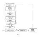
- a method of protecting a multi-function drive axle system from damagecomprising the steps of: determining the axle torque and speed from sensors positioned on the multi-function drive axle system; using the axle torque and speed to approximate damage values for the driveline of the multi-function drive axle system; comparing the approximated values of driveline damage with driveline damage durability targets; identifying if the approximated values of driveline damage exceed the driveline damage durability targets; and limiting the engine torque and/or speed to produce an axle torque and speed corresponding to driveline damage values that do not exceed the driveline damage durability targets.
- FIG. 1is a schematic view of an embodiment of a tandem drive axle system
- FIG. 2is a flow diagram depicting one embodiment of the method of protecting a multi-function drive axle system from damage by limiting excessive engine torque and speed;
- FIG. 3is a flow diagram depicting another embodiment of the method of protecting a multi-function drive axle system from damage by limiting excessive engine torque and speed.
- the embodimentsrelate to a method for limiting damage to a multi-function axle system.
- the multi-function axle systemhas at least two axle assemblies wherein one of the axle assemblies can be selectively engaged/disengaged.
- the multi-function axle systemis a tandem drive axle system.
- the multi-function axle systemcan be as disclosed in U.S. Pat. Nos. 8,523,738 and 8,911,321 hereby incorporated by reference.
- the above-referenced U.S. Pat. Nos. 8,523,738 and 8,911,321disclose exemplary embodiments of a multi-function axle system.
- the drive axle systemmay include fewer or more assemblies or components or have various configurations.
- the drive axle system 10is a tandem drive axle system.
- the drive axle system 10includes a forward axle system (or axle assembly) 12 and a rear axle system (or axle assembly) 14 .
- Rotational energyis provided to the tandem drive axle system 10 through an input shaft 16 that is rotated by an internal combustion engine (not shown).
- a gerotor pump 18is rotated by the input shaft 16 .
- the gerotor pump 18pumps lubricant to rotating parts in the forward axle system 12 regardless of the operating condition of the forward axle system 12 , which can be selectively engaged and disengaged.
- the input shaft 16is connected to an interaxle differential (IAD) 20 .
- the IAD 20comprises at least two side gears 22 and at least two pinion gears 24 , with the side gears 22 and pinion gears 24 being in driving engagement with one another.
- the side gears 22 and pinion gears 24are located within an IAD carrier 26 .
- the IAD 20provides differential action between the forward axle system 12 and the rear axle system 14 .
- An output shaft 28 connected to one of the IAD side gears 22is connected to a first end of a propeller shaft 30 .
- the propeller shaft 30extends between the forward axle system 12 and the rear axle system 14 .
- a second end of the propeller shaft 30is connected to a rear pinion gear 32 .
- the rear pinion gear 32is drivingly connected to a rear ring gear 34 .
- the rear ring gear 34is connected to a rear differential 36 .
- the rear differential 36includes at least two side gears 38 and at least two pinion gears 40 to permit differential rotation between the wheels (not shown) on a right axle shaft 42 and a left axle shaft 44 connected to the side gears 38 .
- a first concentric shaft 46is radially located about the input shaft 16 .
- the first concentric shaft 46is connected to one of the IAD side gears 22 .
- the first concentric shaft 46also carries a dog clutch gear 48 .
- a synchronizer system 50is radially concentric with the first concentric shaft 46 .
- the synchronizer system 50comprises a cone assembly 52 .
- the cone assembly 52may be selectively moved in the axial direction into and out of engagement with a plate assembly 54 a portion of which is angled to receive the cone assembly 52 .
- the cone assembly 52is rotatable and via the axial movement, it may be brought into selective engagement with the plate assembly 54 .
- the rotation of the cone assembly 52is imparted to the plate assembly 54 , which causes the plate assembly 54 to rotate.
- the plate assembly 54is matched or substantially matched to the same rotational speed of the cone assembly 52 .
- a shift fork 56moves a dog clutch ring 58 on the dog clutch gear 48 also to a synchronizer gear 60 .
- the dog clutch ring 58rotationally connects the synchronizer gear 60 and the dog clutch gear 48 .
- the synchronizer system 50is selectively connected to, and thus selectively rotates, a drop gear set 62 .
- the drop gear set 62is connected to an input shaft 64 of the forward axle system 12 .
- the input shaft 64is provided with, or connected to, a pinion shaft 66 .
- the pinion shaft 66has a pinion gear 68 .
- the pinion gear 68is connected to a differential ring gear 70 .
- the ring gear 70is connected to a differential carrier 72 . At least two pinion gears 74 and at least two side gears 76 are located within the differential carrier 72 .
- Shaftsextend into the differential carrier 72 and connect with the side gears 76 .
- the shaftsextend outboard the differential carrier 72 .
- the shaftsmay be full length shafts or they may be stub shafts.
- First and second stub shafts 78 , 80are shown extending from the carrier 72 .
- a clutch 82such as a dog-type clutch, may be located on the second stub shaft 80 .
- the clutch 82may selectively move along the stub shaft 80 for connecting and disconnecting the stub shaft 80 with an axle shaft 84 rotationally supporting at least one wheel and tire (not shown).
- the clutch 82may include a first set of splines or gears 82 A that are selectively connected with a second set of splines or gears 82 B via a clutch ring 82 C.
- the clutch ring 82 Cselectively connects the gears 82 A, 82 B when moved by a shift fork 82 D.
- a selectively engagable clutch 86may be provided at the interaxle differential 20 for locking the output shaft 28 to the input shaft 16 .
- the first concentric shaft 46is selectively connected to the IAD carrier 26 with the clutch 86 .
- the IAD carrier 26is provided with a set of teeth, a gear, or splines; teeth 88 will be used in the following description.
- the clutch 86such as a dog-type clutch, is designed to selectively engage and disengage with the IAD housing teeth 88 .
- the clutch 86selectively joins the IAD carrier teeth 88 with a gear 48 on the concentric shaft 46 .
- tandem drive axle system 10can be operated in different modes.
- the rear axle system 14is engaged in the drive-line full time and the forward axle system 12 is engaged for only intermittent use, such as for startup and low speed traction conditions.
- the forward axle system 12is disengaged and allowed to idle most of the time.
- the tandemhas three modes of operation: first, 6 ⁇ 2 with the forward axle system 12 disconnected; second, 6 ⁇ 4 with the IAD open with the forward and rear axle systems 12 , 14 providing drive; and third, 6 ⁇ 4 with the IAD locked and the forward and rear axle systems 12 , 14 providing drive.
- the synchronizer system 50is not engaged so rotational power transfers from the engine to the rear axle system 14 through the locked IAD 20 ; no rotational power is transmitted to the forward axle system 12 .
- the clutch 86 between the stub shaft 80 and axle shaft 84is unlocked so that the forward axle system 12 is not rotating, thus reducing, or preventing, oil churning losses and spin loses.
- the synchronizer system 50is engaged thus connecting both the forward and the rear axle systems 12 , 14 to the engine.
- the IAD 20is unlocked.
- the differential carrier 26is not locked to the concentric shaft 46 with the interaxle differential clutch 86 .
- the fork 82 Dmoves the ring 82 C to connect the stub shaft 80 and the axle shaft 84 so that they rotate together.
- the clutches 82 , 86 on the concentric shaft 46 and the stub shaft 80 of the axle shaft 84 of the forward axle system 12are engaged.
- the forward axle system 12provides rotational power to the forward wheels and tires.
- the IAD 20is locked so that the forward and rear axle systems 12 , 14 are driven at the same speed.
- the differential carrier 26is locked to the concentric shaft 46 with the interaxle differential clutch 86 .
- the fork 82 Dmoves the ring 82 C to connect the stub shaft 80 and the axle shaft 84 so that they are rotate together.
- the drive axle system 10can include a control system 110 .
- the control system 110includes a controller 112 and one or more sensors 114 or a sensor array.
- the sensors 114can be intelligent sensors, self-validating sensors and smart sensors with embedded diagnostics.
- the controller 112is configured to receive signals and communicate with the sensors 114 .
- the one or more sensors 114are used to monitor performance of the drive axle system 10 .
- the sensors 114can collect data from the driveline of the vehicle including, but not limited to, the torque and speed of the axles.
- the speed of rotation and the torqueare indicative of the speed of rotation and torque of the engine.
- the sensors 114are mounted along the axles of the drive axle system 10 , but can also be mounted elsewhere on the vehicle.
- control system 110includes additional, discrete sensors 114 beyond sensors already included in other components of the vehicle. In another embodiment, no additional sensors or sensed data relay systems are required beyond what are already included in the drive axle system 10 .
- the control system 110can also include a vehicle communication datalink 116 in communication with the sensors 114 and the controller 112 .
- the sensors 114generate signals that can be directly transmitted to the controller 112 or transmitted via the datalink 116 or a similar network.
- the controller 112can be integrated into an existing controller system in the vehicle including, but not limited to, an engine controller, a transmission controller, etc. or can be a discrete unit included in the control system 110 .
- the controller 112may communicate a vehicle communication datalink message (comm. link J1939 or the like) to other components of the drive axle system 10 including, but not limited to, the engine.
- the controller 112is an electrical control unit (ECU).
- ECUelectrical control unit
- the ECU hereincan be configured with hardware alone, or to run software, that permits the ECU to send, receive, process and store data and to electrically communicate with sensors 114 , other components of the drive axle system 10 or other ECUs in the vehicle.
- controller 112can include a microprocessor.
- the microprocessoris capable of receiving signals, performing calculations based on those signals and storing data received from the sensors and/or programmed into the microprocessor.
- the engaged axlecan experience and increase torque and damaging cycles.
- the torque and engine speedcan be limited when necessary.
- the sensors 114obtain speed and torque information by taking direct, non-predictive measurements of the speed (Sm) and torque (Tm) of the axles of the drive axle system 10 .
- the sensors 114communicate the measured speed and torque Sm, Tm to the controller 112 .
- the measured values Sm, Tmcan be sent directly from the sensors 114 to the controller 112 or the datalink 116 can be used to communicate the measured speed and torque Sm, Tm to the controller 112 .
- the sensors 114can be designed to obtain other data relating to the operating conditions of the drive axle system 10 beyond the speed and torque of the axle and the sensors 114 can send signals communicating this information to the controller 112 by similar means.
- the controller 112receives the speed and torque values Sm, Tm, or other operating conditions values, obtained by the sensors 114 and, utilizing a simple approximation method, approximates the damage caused to the driveline.
- the damage to the drivelinecan include the damage to the gears (Dg) and/or the damage to the bearings (Db) of the drive axle system 10 by the speed, torque or other operating conditions of the drive axle system 10 .
- the damage Dgis the amount of gear tooth bending, pitting, etc.
- the damagecan include the amount of damage or wear to the bearing Db. Additional damage values relating to the damage to the driveline can be approximated based on the other operating conditions obtained by the sensors 114 .
- the simple approximation methodbases the damage values Dg, Db on historical test data results programmed into the microprocessor. This collected test data is based on a number of factors monitored in the drive axle system 10 in test conditions that predicts the durability and life of the axle.
- the microprocessorcan also contain operating tables, algorithms and other control logic required to perform the simple approximations.
- the controller 112compares the approximated damage values Dg, Db to known durability targets Dgt, Dbt.
- the durability targets Dgt, Dbtare known values for the amount of damage to the driveline, including the gears and/or bearings, for which the drive axle system 10 can withstand and still meet the required lifespan of the drive axle system 10 .
- These durability targets Dgt, Dbtare based on the individual needs of each vehicle depending on the application and purpose of the vehicle and the expected lifespan of the vehicle.
- control system 110can monitor the damage values Dg, Db individually and/or as an accumulation against the durability targets Dgt, Dbt.
- a cumulative databasecan be established in the control system 112 and stored by the microprocessor. This cumulative data set can then be used to adjust the durability target Dgt, Dbt accordingly and provide additional basis for how the simplified approximation is realized.
- the controller 112can compare the approximated damage values Dg, Db to the durability target values Dgt, Dbt. If the approximated values Dg, Db exceed the durability target values Dgt, Dbt, the controller 112 can send signals to drive axle system 10 to reduce the torque and speed of the engine such that the measured speed and torque Tm, Sm produce Dg, Db values less than the Dgt, Dbt as depicted in the flow diagram in FIG. 2 .
- the controller 112can use the measured values Tm, Sm and the simple approximation method to determine threshold values for the speed and torque Tmax, Smax that do not result in damage values Dg, Db that exceed the durability targets Dgt, Dbt. If the sensors 114 obtain measured values Tm, Sm that exceed the speed and torque threshold values Tmax, Smax, the controller 112 can signal the drive axle system 10 to reduce the engine torque and speed such that the measured speed and torque Sm, Tm are less than the threshold speed and torque Smax, Tmax as depicted in the flow diagram in FIG. 3 .
- the engine torquecan be managed by various methods including, but not limited to, throttle override/cutoff, spark reduction, etc.
- torque demandsare made by the vehicle operator directly or indirectly via cruise control, etc. If the operator indicates throttle demand resulting in Tm or Dg/Db values in excess of the threshold Tmax or Dgt/Dbt, then actual engine torque could be limited by overriding the throttle request, in a manner similar to overriding engine behavior during cruise control operation or during transmission shifting.
- the engine speedcan be limited by various methods known in the art. By limiting the engine speed of the drive axle system 10 , the rate of damaging cycles also is reduced.
- the engaged axlecan experience increase torque and damaging cycles where the Sm, Tm or Dg/Db values are in excess of the threshold values Smax, Tmax or Dgt/Dbt. If the vehicle operator then requests additional torque or speed, the control system 112 overrides this request. The vehicle operator may note the expected requested torque is not being provided and the operator would likely change the transmission to a lower gear. Changing the transmission to a lower gear creates the opportunity to re-engage the disengaged axle and restore full engine torque, or for at least slowing the vehicle down and continuing at a lower speed with limited engine torque (and slower cycle accumulation) preventing further damage to the drive axle system 10 .
Landscapes
- Engineering & Computer Science (AREA)
- Chemical & Material Sciences (AREA)
- Combustion & Propulsion (AREA)
- Mechanical Engineering (AREA)
- General Engineering & Computer Science (AREA)
- Transportation (AREA)
- Computer Hardware Design (AREA)
- Microelectronics & Electronic Packaging (AREA)
- Arrangement And Driving Of Transmission Devices (AREA)
Abstract
Description
Claims (15)
Priority Applications (2)
| Application Number | Priority Date | Filing Date | Title |
|---|---|---|---|
| US15/238,088US10495010B2 (en) | 2016-08-16 | 2016-08-16 | Damage protection for multi-function axle |
| EP17186257.6AEP3312068A1 (en) | 2016-08-16 | 2017-08-15 | Damage protection for multi-function axle |
Applications Claiming Priority (1)
| Application Number | Priority Date | Filing Date | Title |
|---|---|---|---|
| US15/238,088US10495010B2 (en) | 2016-08-16 | 2016-08-16 | Damage protection for multi-function axle |
Publications (2)
| Publication Number | Publication Date |
|---|---|
| US20180051637A1 US20180051637A1 (en) | 2018-02-22 |
| US10495010B2true US10495010B2 (en) | 2019-12-03 |
Family
ID=59649517
Family Applications (1)
| Application Number | Title | Priority Date | Filing Date |
|---|---|---|---|
| US15/238,088Expired - Fee RelatedUS10495010B2 (en) | 2016-08-16 | 2016-08-16 | Damage protection for multi-function axle |
Country Status (2)
| Country | Link |
|---|---|
| US (1) | US10495010B2 (en) |
| EP (1) | EP3312068A1 (en) |
Families Citing this family (4)
| Publication number | Priority date | Publication date | Assignee | Title |
|---|---|---|---|---|
| CN110594408B (en)* | 2018-06-13 | 2021-05-18 | 上海汽车集团股份有限公司 | Vehicle, power transmission system, shift actuator and shift method thereof |
| JP7390231B2 (en)* | 2020-03-26 | 2023-12-01 | 本田技研工業株式会社 | Vehicle control device and vehicle management system |
| US11718174B2 (en) | 2021-05-25 | 2023-08-08 | Ford Global Technologies, Llc | Vehicle with engine power limiting based on clutch capacity |
| CN115675476B (en)* | 2022-11-28 | 2025-09-19 | 长城汽车股份有限公司 | Vehicle detection method and device and vehicle |
Citations (22)
| Publication number | Priority date | Publication date | Assignee | Title |
|---|---|---|---|---|
| EP0137247A2 (en) | 1983-09-26 | 1985-04-17 | WABCO Westinghouse Fahrzeugbremsen GmbH | Device for preventing overheating of a clutch |
| EP0512726A2 (en) | 1991-05-09 | 1992-11-11 | Eaton Corporation | Driveline torque limit control strategy using engine control |
| US6349252B1 (en) | 1999-04-15 | 2002-02-19 | Komatsu Ltd. | Information management device for construction machinery |
| US20020095985A1 (en)* | 2000-12-13 | 2002-07-25 | Genise Thomas A. | Transmission gear life monitor system |
| US6615126B1 (en) | 2002-03-05 | 2003-09-02 | Daimlerchrysler Corporation | Torque management based traction control system |
| US6814053B2 (en) | 2002-11-06 | 2004-11-09 | Detroit Diesel Corporation | Method and apparatus for limiting engine operation in a programmable range |
| US6842689B2 (en) | 2002-05-15 | 2005-01-11 | Caterpillar Inc | System for dynamically controlling power provided by an engine |
| US6873917B2 (en) | 2002-04-11 | 2005-03-29 | Robert Bosch Gmbh | Method and control unit for determining the probability of failure of a motor-vehicle component |
| US7076396B2 (en) | 2000-02-17 | 2006-07-11 | Robert Bosch Gmbh | Method and device for determining the remaining serviceable life of a product |
| US7283932B2 (en) | 2000-07-20 | 2007-10-16 | Albihns Goteborg Ab | Method for estimating damage to an object, and method and system for controlling the use of the object |
| US20070299592A1 (en)* | 2004-08-13 | 2007-12-27 | Romer Richard A | Drivetrain protection and management system |
| US7318007B2 (en) | 2003-12-31 | 2008-01-08 | United Technologies Corporation | Real time gear box health management system and method of using the same |
| US20080227596A1 (en) | 2007-03-15 | 2008-09-18 | Caterpillar Inc. | Method for limiting drive train torque |
| US7440832B2 (en) | 2003-08-27 | 2008-10-21 | Volvo Lastvagnar Ab | Method and arrangement for controlling actual torque in a land vehicle driveline |
| US7914250B2 (en) | 2006-12-08 | 2011-03-29 | General Electric Company | Method and system for estimating life of a gearbox |
| US7953559B2 (en) | 2005-04-28 | 2011-05-31 | Caterpillar Inc. | Systems and methods for maintaining load histories |
| US8073653B2 (en) | 2002-12-23 | 2011-12-06 | Caterpillar Inc. | Component life indicator |
| US8234050B2 (en) | 2009-09-02 | 2012-07-31 | Magna Powertrain Usa, Inc. | Torque limiting clutch with engine torque management for thermal protection |
| US8523738B2 (en) | 2011-01-21 | 2013-09-03 | Dana Heavy Vehicle Systems Group, Llc | Method of shifting a tandem drive axle having an inter-axle differential |
| US20140057751A1 (en) | 2012-08-22 | 2014-02-27 | GM Global Technology Operations LLC | Multi-speed transmission |
| US8911321B2 (en) | 2012-08-23 | 2014-12-16 | Dana Heavy Vehicle Systems Group, Llc | Tandem axle system |
| US9014918B2 (en) | 2012-10-12 | 2015-04-21 | Cummins Inc. | Health monitoring systems and techniques for vehicle systems |
Family Cites Families (1)
| Publication number | Priority date | Publication date | Assignee | Title |
|---|---|---|---|---|
| US5992243A (en)* | 1996-12-21 | 1999-11-30 | Dana Corporation | Four-wheel drive transfer case with torque sensing |
- 2016
- 2016-08-16USUS15/238,088patent/US10495010B2/ennot_activeExpired - Fee Related
- 2017
- 2017-08-15EPEP17186257.6Apatent/EP3312068A1/ennot_activeWithdrawn
Patent Citations (25)
| Publication number | Priority date | Publication date | Assignee | Title |
|---|---|---|---|---|
| EP0137247A2 (en) | 1983-09-26 | 1985-04-17 | WABCO Westinghouse Fahrzeugbremsen GmbH | Device for preventing overheating of a clutch |
| EP0512726A2 (en) | 1991-05-09 | 1992-11-11 | Eaton Corporation | Driveline torque limit control strategy using engine control |
| US6349252B1 (en) | 1999-04-15 | 2002-02-19 | Komatsu Ltd. | Information management device for construction machinery |
| US7076396B2 (en) | 2000-02-17 | 2006-07-11 | Robert Bosch Gmbh | Method and device for determining the remaining serviceable life of a product |
| US7283932B2 (en) | 2000-07-20 | 2007-10-16 | Albihns Goteborg Ab | Method for estimating damage to an object, and method and system for controlling the use of the object |
| US20020095985A1 (en)* | 2000-12-13 | 2002-07-25 | Genise Thomas A. | Transmission gear life monitor system |
| US6526816B2 (en) | 2000-12-13 | 2003-03-04 | Eaton Corporation | Transmission gear life monitor system |
| US6615126B1 (en) | 2002-03-05 | 2003-09-02 | Daimlerchrysler Corporation | Torque management based traction control system |
| US6873917B2 (en) | 2002-04-11 | 2005-03-29 | Robert Bosch Gmbh | Method and control unit for determining the probability of failure of a motor-vehicle component |
| US6842689B2 (en) | 2002-05-15 | 2005-01-11 | Caterpillar Inc | System for dynamically controlling power provided by an engine |
| US6814053B2 (en) | 2002-11-06 | 2004-11-09 | Detroit Diesel Corporation | Method and apparatus for limiting engine operation in a programmable range |
| US8073653B2 (en) | 2002-12-23 | 2011-12-06 | Caterpillar Inc. | Component life indicator |
| US7440832B2 (en) | 2003-08-27 | 2008-10-21 | Volvo Lastvagnar Ab | Method and arrangement for controlling actual torque in a land vehicle driveline |
| US7318007B2 (en) | 2003-12-31 | 2008-01-08 | United Technologies Corporation | Real time gear box health management system and method of using the same |
| US7421327B2 (en) | 2004-08-13 | 2008-09-02 | Arvinmeritor Technology, Llc | Drivetrain protection and management system |
| US7356401B2 (en) | 2004-08-13 | 2008-04-08 | Arvinmeritor Technology, Llc | Drivetrain protection and management system |
| US20070299592A1 (en)* | 2004-08-13 | 2007-12-27 | Romer Richard A | Drivetrain protection and management system |
| US7953559B2 (en) | 2005-04-28 | 2011-05-31 | Caterpillar Inc. | Systems and methods for maintaining load histories |
| US7914250B2 (en) | 2006-12-08 | 2011-03-29 | General Electric Company | Method and system for estimating life of a gearbox |
| US20080227596A1 (en) | 2007-03-15 | 2008-09-18 | Caterpillar Inc. | Method for limiting drive train torque |
| US8234050B2 (en) | 2009-09-02 | 2012-07-31 | Magna Powertrain Usa, Inc. | Torque limiting clutch with engine torque management for thermal protection |
| US8523738B2 (en) | 2011-01-21 | 2013-09-03 | Dana Heavy Vehicle Systems Group, Llc | Method of shifting a tandem drive axle having an inter-axle differential |
| US20140057751A1 (en) | 2012-08-22 | 2014-02-27 | GM Global Technology Operations LLC | Multi-speed transmission |
| US8911321B2 (en) | 2012-08-23 | 2014-12-16 | Dana Heavy Vehicle Systems Group, Llc | Tandem axle system |
| US9014918B2 (en) | 2012-10-12 | 2015-04-21 | Cummins Inc. | Health monitoring systems and techniques for vehicle systems |
Also Published As
| Publication number | Publication date |
|---|---|
| EP3312068A1 (en) | 2018-04-25 |
| US20180051637A1 (en) | 2018-02-22 |
Similar Documents
| Publication | Publication Date | Title |
|---|---|---|
| US7729839B2 (en) | Automated inter-axle differential lock sensor configuration and calibration method | |
| US10495010B2 (en) | Damage protection for multi-function axle | |
| US8050814B2 (en) | Apparatus and method for determining remaining transmission oil life | |
| EP1990230B1 (en) | Drive system for vehicles with at least two drivable vehicle axles | |
| EP2770229B1 (en) | Axle assembly and method of lubrication control | |
| US11667193B2 (en) | Method of controlling a tandem axle assembly | |
| US8475334B2 (en) | Load-sensitive automatic transmission system for agricultural electric vehicle | |
| US8888658B2 (en) | Transfer case utilizing an on-demand centrifugally governed hydraulic power supply to perform both range shift and on-demand four wheel drive | |
| US9180859B2 (en) | Vehicle and method of controlling a vehicle | |
| US20110196584A1 (en) | Control system and method for automatic selection of a low range gear ratio for a vehicle drivetrain | |
| US10174694B2 (en) | Method of optimizing vehicle performance based on countershaft acceleration | |
| EP1832779A1 (en) | Electrorheological inertia brake | |
| US20180319278A1 (en) | Tandem Axle With Disconnect Coast | |
| EP3008362B1 (en) | Vehicle transmission and a method for operating a vehicle transmission | |
| US20200062112A1 (en) | Tandem axle with disconnect coast | |
| US20200255015A1 (en) | Method for operating a drive train of a vehicle | |
| CN103562024A (en) | Brake device in a vehicle | |
| US20200215907A1 (en) | Disconnect mechanism for a tandem axle system | |
| JP2024128839A (en) | Control device for vehicle drive device equipped with differential mechanism | |
| CN102452397B (en) | Automatically controlling of driveline states |
Legal Events
| Date | Code | Title | Description |
|---|---|---|---|
| AS | Assignment | Owner name:DANA HEAVY VEHICLE SYSTEMS GROUP, LLC, OHIO Free format text:ASSIGNMENT OF ASSIGNORS INTEREST;ASSIGNORS:NELLUMS, RICHARD;REMBOSKI, DONALD J.;WESOLOWSKI, STEVEN J.;SIGNING DATES FROM 20160824 TO 20160913;REEL/FRAME:039779/0913 | |
| STPP | Information on status: patent application and granting procedure in general | Free format text:NON FINAL ACTION MAILED | |
| STPP | Information on status: patent application and granting procedure in general | Free format text:RESPONSE TO NON-FINAL OFFICE ACTION ENTERED AND FORWARDED TO EXAMINER | |
| STPP | Information on status: patent application and granting procedure in general | Free format text:NOTICE OF ALLOWANCE MAILED -- APPLICATION RECEIVED IN OFFICE OF PUBLICATIONS | |
| STPP | Information on status: patent application and granting procedure in general | Free format text:PUBLICATIONS -- ISSUE FEE PAYMENT VERIFIED | |
| STCF | Information on status: patent grant | Free format text:PATENTED CASE | |
| AS | Assignment | Owner name:CITIBANK, N.A., NEW YORK Free format text:SECURITY AGREEMENT (BRIDGE);ASSIGNORS:DANA HEAVY VEHICLE SYSTEMS GROUP, LLC;DANA LIMITED;DANA AUTOMOTIVE SYSTEMS GROUP, LLC;AND OTHERS;REEL/FRAME:052459/0001 Effective date:20200416 Owner name:CITIBANK, N.A., NEW YORK Free format text:SECURITY AGREEMENT SUPPLEMENT;ASSIGNORS:DANA HEAVY VEHICLE SYSTEMS GROUP, LLC;DANA LIMITED;DANA AUTOMOTIVE SYSTEMS GROUP, LLC;AND OTHERS;REEL/FRAME:052459/0224 Effective date:20200416 | |
| AS | Assignment | Owner name:FAIRFIELD MANUFACTURING COMPANY, INC., OHIO Free format text:RELEASE BY SECURED PARTY;ASSIGNOR:CITIBANK, N.A.;REEL/FRAME:053309/0686 Effective date:20200619 Owner name:DANA LIMITED, OHIO Free format text:RELEASE BY SECURED PARTY;ASSIGNOR:CITIBANK, N.A.;REEL/FRAME:053309/0686 Effective date:20200619 Owner name:DANA HEAVY VEHICLE SYSTEMS GROUP, LLC, OHIO Free format text:RELEASE BY SECURED PARTY;ASSIGNOR:CITIBANK, N.A.;REEL/FRAME:053309/0686 Effective date:20200619 Owner name:DANA AUTOMOTIVE SYSTEMS GROUP, LLC, OHIO Free format text:RELEASE BY SECURED PARTY;ASSIGNOR:CITIBANK, N.A.;REEL/FRAME:053309/0686 Effective date:20200619 | |
| FEPP | Fee payment procedure | Free format text:MAINTENANCE FEE REMINDER MAILED (ORIGINAL EVENT CODE: REM.); ENTITY STATUS OF PATENT OWNER: LARGE ENTITY | |
| LAPS | Lapse for failure to pay maintenance fees | Free format text:PATENT EXPIRED FOR FAILURE TO PAY MAINTENANCE FEES (ORIGINAL EVENT CODE: EXP.); ENTITY STATUS OF PATENT OWNER: LARGE ENTITY | |
| STCH | Information on status: patent discontinuation | Free format text:PATENT EXPIRED DUE TO NONPAYMENT OF MAINTENANCE FEES UNDER 37 CFR 1.362 | |
| FP | Lapsed due to failure to pay maintenance fee | Effective date:20231203 |