US10493235B2 - Reducing mechanical stress on conductors and connection points in a position determinable interventional medical device - Google Patents
Reducing mechanical stress on conductors and connection points in a position determinable interventional medical deviceDownload PDFInfo
- Publication number
- US10493235B2 US10493235B2US14/808,892US201514808892AUS10493235B2US 10493235 B2US10493235 B2US 10493235B2US 201514808892 AUS201514808892 AUS 201514808892AUS 10493235 B2US10493235 B2US 10493235B2
- Authority
- US
- United States
- Prior art keywords
- conductor
- position sensor
- elongate
- deformable member
- medical apparatus
- Prior art date
- Legal status (The legal status is an assumption and is not a legal conclusion. Google has not performed a legal analysis and makes no representation as to the accuracy of the status listed.)
- Expired - Fee Related, expires
Links
- 239000004020conductorSubstances0.000titleclaimsabstractdescription91
- 238000004804windingMethods0.000claimsabstractdescription17
- 230000007935neutral effectEffects0.000claimsabstractdescription16
- 238000003745diagnosisMethods0.000claimsabstractdescription14
- 230000005291magnetic effectEffects0.000claimsdescription12
- 230000035699permeabilityEffects0.000claimsdescription2
- 230000002526effect on cardiovascular systemEffects0.000claims3
- 230000005672electromagnetic fieldEffects0.000description15
- 239000011295pitchSubstances0.000description15
- 230000006835compressionEffects0.000description11
- 238000007906compressionMethods0.000description11
- 239000012530fluidSubstances0.000description9
- 239000000463materialSubstances0.000description9
- 238000000034methodMethods0.000description6
- 238000002679ablationMethods0.000description4
- 239000011253protective coatingSubstances0.000description4
- 230000005684electric fieldEffects0.000description3
- XEEYBQQBJWHFJM-UHFFFAOYSA-NIronChemical compound[Fe]XEEYBQQBJWHFJM-UHFFFAOYSA-N0.000description2
- 239000004696Poly ether ether ketoneSubstances0.000description2
- 239000004698PolyethyleneSubstances0.000description2
- 230000004913activationEffects0.000description2
- 230000003466anti-cipated effectEffects0.000description2
- 230000008859changeEffects0.000description2
- 210000000038chestAnatomy0.000description2
- 238000000576coating methodMethods0.000description2
- 238000006073displacement reactionMethods0.000description2
- 239000003814drugSubstances0.000description2
- 229940079593drugDrugs0.000description2
- 238000010292electrical insulationMethods0.000description2
- 238000002001electrophysiologyMethods0.000description2
- 230000007831electrophysiologyEffects0.000description2
- 239000003302ferromagnetic materialSubstances0.000description2
- 229920002530polyetherether ketonePolymers0.000description2
- -1polyethylenePolymers0.000description2
- 229920000573polyethylenePolymers0.000description2
- 239000005020polyethylene terephthalateSubstances0.000description2
- 229920000139polyethylene terephthalatePolymers0.000description2
- 238000012545processingMethods0.000description2
- 239000007787solidSubstances0.000description2
- 239000000126substanceSubstances0.000description2
- RYGMFSIKBFXOCR-UHFFFAOYSA-NCopperChemical compound[Cu]RYGMFSIKBFXOCR-UHFFFAOYSA-N0.000description1
- 230000005355Hall effectEffects0.000description1
- 239000004677NylonSubstances0.000description1
- 229920002614Polyether block amidePolymers0.000description1
- 239000004642PolyimideSubstances0.000description1
- BQCADISMDOOEFD-UHFFFAOYSA-NSilverChemical compound[Ag]BQCADISMDOOEFD-UHFFFAOYSA-N0.000description1
- 229910001035Soft ferriteInorganic materials0.000description1
- 239000000853adhesiveSubstances0.000description1
- 230000001070adhesive effectEffects0.000description1
- 230000004075alterationEffects0.000description1
- 210000004204blood vesselAnatomy0.000description1
- 210000001124body fluidAnatomy0.000description1
- 210000004556brainAnatomy0.000description1
- 210000000748cardiovascular systemAnatomy0.000description1
- 238000003486chemical etchingMethods0.000description1
- 238000004891communicationMethods0.000description1
- 230000003750conditioning effectEffects0.000description1
- 229910052802copperInorganic materials0.000description1
- 239000010949copperSubstances0.000description1
- 230000007812deficiencyEffects0.000description1
- 238000001514detection methodMethods0.000description1
- 210000002249digestive systemAnatomy0.000description1
- 238000002565electrocardiographyMethods0.000description1
- 230000005670electromagnetic radiationEffects0.000description1
- 238000001125extrusionMethods0.000description1
- 238000002594fluoroscopyMethods0.000description1
- 239000011888foilSubstances0.000description1
- PCHJSUWPFVWCPO-UHFFFAOYSA-NgoldChemical compound[Au]PCHJSUWPFVWCPO-UHFFFAOYSA-N0.000description1
- 229910052737goldInorganic materials0.000description1
- 239000010931goldSubstances0.000description1
- 238000003384imaging methodMethods0.000description1
- 230000006872improvementEffects0.000description1
- 238000002347injectionMethods0.000description1
- 239000007924injectionSubstances0.000description1
- 238000009413insulationMethods0.000description1
- 229910052742ironInorganic materials0.000description1
- 230000002262irrigationEffects0.000description1
- 238000003973irrigationMethods0.000description1
- 210000003734kidneyAnatomy0.000description1
- 210000004185liverAnatomy0.000description1
- 210000004072lungAnatomy0.000description1
- 238000013507mappingMethods0.000description1
- 239000003550markerSubstances0.000description1
- 238000005259measurementMethods0.000description1
- 239000002184metalSubstances0.000description1
- 229910052751metalInorganic materials0.000description1
- 150000002739metalsChemical class0.000description1
- 238000012544monitoring processMethods0.000description1
- 238000000465mouldingMethods0.000description1
- 229910000595mu-metalInorganic materials0.000description1
- 230000017074necrotic cell deathEffects0.000description1
- 229910001000nickel titaniumInorganic materials0.000description1
- HLXZNVUGXRDIFK-UHFFFAOYSA-Nnickel titaniumChemical compound[Ti].[Ti].[Ti].[Ti].[Ti].[Ti].[Ti].[Ti].[Ti].[Ti].[Ti].[Ni].[Ni].[Ni].[Ni].[Ni].[Ni].[Ni].[Ni].[Ni].[Ni].[Ni].[Ni].[Ni].[Ni]HLXZNVUGXRDIFK-UHFFFAOYSA-N0.000description1
- 229920001778nylonPolymers0.000description1
- RVTZCBVAJQQJTK-UHFFFAOYSA-Noxygen(2-);zirconium(4+)Chemical compound[O-2].[O-2].[Zr+4]RVTZCBVAJQQJTK-UHFFFAOYSA-N0.000description1
- 239000002907paramagnetic materialSubstances0.000description1
- 230000000144pharmacologic effectEffects0.000description1
- 229920001721polyimidePolymers0.000description1
- 239000004814polyurethaneSubstances0.000description1
- 229920002635polyurethanePolymers0.000description1
- 239000004800polyvinyl chlorideSubstances0.000description1
- 230000008569processEffects0.000description1
- 229910001285shape-memory alloyInorganic materials0.000description1
- 229910052709silverInorganic materials0.000description1
- 239000004332silverSubstances0.000description1
- 238000005476solderingMethods0.000description1
- 239000010935stainless steelSubstances0.000description1
- 229910001220stainless steelInorganic materials0.000description1
- 239000003351stiffenerSubstances0.000description1
- 210000002784stomachAnatomy0.000description1
- 229910000601superalloyInorganic materials0.000description1
- 238000002604ultrasonographyMethods0.000description1
- 230000000007visual effectEffects0.000description1
- 229910000859α-FeInorganic materials0.000description1
Images


Classifications
- A—HUMAN NECESSITIES
- A61—MEDICAL OR VETERINARY SCIENCE; HYGIENE
- A61M—DEVICES FOR INTRODUCING MEDIA INTO, OR ONTO, THE BODY; DEVICES FOR TRANSDUCING BODY MEDIA OR FOR TAKING MEDIA FROM THE BODY; DEVICES FOR PRODUCING OR ENDING SLEEP OR STUPOR
- A61M25/00—Catheters; Hollow probes
- A61M25/01—Introducing, guiding, advancing, emplacing or holding catheters
- A—HUMAN NECESSITIES
- A61—MEDICAL OR VETERINARY SCIENCE; HYGIENE
- A61B—DIAGNOSIS; SURGERY; IDENTIFICATION
- A61B17/00—Surgical instruments, devices or methods
- A61B17/32—Surgical cutting instruments
- A61B17/3205—Excision instruments
- A61B17/3207—Atherectomy devices working by cutting or abrading; Similar devices specially adapted for non-vascular obstructions
- A—HUMAN NECESSITIES
- A61—MEDICAL OR VETERINARY SCIENCE; HYGIENE
- A61B—DIAGNOSIS; SURGERY; IDENTIFICATION
- A61B34/00—Computer-aided surgery; Manipulators or robots specially adapted for use in surgery
- A61B34/20—Surgical navigation systems; Devices for tracking or guiding surgical instruments, e.g. for frameless stereotaxis
- A—HUMAN NECESSITIES
- A61—MEDICAL OR VETERINARY SCIENCE; HYGIENE
- A61B—DIAGNOSIS; SURGERY; IDENTIFICATION
- A61B5/00—Measuring for diagnostic purposes; Identification of persons
- A61B5/06—Devices, other than using radiation, for detecting or locating foreign bodies ; Determining position of diagnostic devices within or on the body of the patient
- A61B5/061—Determining position of a probe within the body employing means separate from the probe, e.g. sensing internal probe position employing impedance electrodes on the surface of the body
- A61B5/062—Determining position of a probe within the body employing means separate from the probe, e.g. sensing internal probe position employing impedance electrodes on the surface of the body using magnetic field
- A—HUMAN NECESSITIES
- A61—MEDICAL OR VETERINARY SCIENCE; HYGIENE
- A61B—DIAGNOSIS; SURGERY; IDENTIFICATION
- A61B18/00—Surgical instruments, devices or methods for transferring non-mechanical forms of energy to or from the body
- A61B18/04—Surgical instruments, devices or methods for transferring non-mechanical forms of energy to or from the body by heating
- A61B18/12—Surgical instruments, devices or methods for transferring non-mechanical forms of energy to or from the body by heating by passing a current through the tissue to be heated, e.g. high-frequency current
- A61B18/14—Probes or electrodes therefor
- A61B18/1492—Probes or electrodes therefor having a flexible, catheter-like structure, e.g. for heart ablation
- A—HUMAN NECESSITIES
- A61—MEDICAL OR VETERINARY SCIENCE; HYGIENE
- A61B—DIAGNOSIS; SURGERY; IDENTIFICATION
- A61B18/00—Surgical instruments, devices or methods for transferring non-mechanical forms of energy to or from the body
- A61B18/18—Surgical instruments, devices or methods for transferring non-mechanical forms of energy to or from the body by applying electromagnetic radiation, e.g. microwaves
- A61B18/20—Surgical instruments, devices or methods for transferring non-mechanical forms of energy to or from the body by applying electromagnetic radiation, e.g. microwaves using laser
- A61B18/22—Surgical instruments, devices or methods for transferring non-mechanical forms of energy to or from the body by applying electromagnetic radiation, e.g. microwaves using laser the beam being directed along or through a flexible conduit, e.g. an optical fibre; Couplings or hand-pieces therefor
- A61B18/24—Surgical instruments, devices or methods for transferring non-mechanical forms of energy to or from the body by applying electromagnetic radiation, e.g. microwaves using laser the beam being directed along or through a flexible conduit, e.g. an optical fibre; Couplings or hand-pieces therefor with a catheter
- A—HUMAN NECESSITIES
- A61—MEDICAL OR VETERINARY SCIENCE; HYGIENE
- A61B—DIAGNOSIS; SURGERY; IDENTIFICATION
- A61B17/00—Surgical instruments, devices or methods
- A61B17/00234—Surgical instruments, devices or methods for minimally invasive surgery
- A61B2017/00238—Type of minimally invasive operation
- A61B2017/00243—Type of minimally invasive operation cardiac
- A61B2017/00247—Making holes in the wall of the heart, e.g. laser Myocardial revascularization
- A61B2017/00252—Making holes in the wall of the heart, e.g. laser Myocardial revascularization for by-pass connections, i.e. connections from heart chamber to blood vessel or from blood vessel to blood vessel
- A—HUMAN NECESSITIES
- A61—MEDICAL OR VETERINARY SCIENCE; HYGIENE
- A61B—DIAGNOSIS; SURGERY; IDENTIFICATION
- A61B34/00—Computer-aided surgery; Manipulators or robots specially adapted for use in surgery
- A61B34/20—Surgical navigation systems; Devices for tracking or guiding surgical instruments, e.g. for frameless stereotaxis
- A61B2034/2046—Tracking techniques
- A61B2034/2051—Electromagnetic tracking systems
- A—HUMAN NECESSITIES
- A61—MEDICAL OR VETERINARY SCIENCE; HYGIENE
- A61B—DIAGNOSIS; SURGERY; IDENTIFICATION
- A61B34/00—Computer-aided surgery; Manipulators or robots specially adapted for use in surgery
- A61B34/20—Surgical navigation systems; Devices for tracking or guiding surgical instruments, e.g. for frameless stereotaxis
- A61B2034/2072—Reference field transducer attached to an instrument or patient
- A—HUMAN NECESSITIES
- A61—MEDICAL OR VETERINARY SCIENCE; HYGIENE
- A61M—DEVICES FOR INTRODUCING MEDIA INTO, OR ONTO, THE BODY; DEVICES FOR TRANSDUCING BODY MEDIA OR FOR TAKING MEDIA FROM THE BODY; DEVICES FOR PRODUCING OR ENDING SLEEP OR STUPOR
- A61M25/00—Catheters; Hollow probes
- A61M25/01—Introducing, guiding, advancing, emplacing or holding catheters
- A61M25/0105—Steering means as part of the catheter or advancing means; Markers for positioning
- A61M2025/0166—Sensors, electrodes or the like for guiding the catheter to a target zone, e.g. image guided or magnetically guided
- A—HUMAN NECESSITIES
- A61—MEDICAL OR VETERINARY SCIENCE; HYGIENE
- A61M—DEVICES FOR INTRODUCING MEDIA INTO, OR ONTO, THE BODY; DEVICES FOR TRANSDUCING BODY MEDIA OR FOR TAKING MEDIA FROM THE BODY; DEVICES FOR PRODUCING OR ENDING SLEEP OR STUPOR
- A61M29/00—Dilators with or without means for introducing media, e.g. remedies
- A61M29/02—Dilators made of swellable material
- A—HUMAN NECESSITIES
- A61—MEDICAL OR VETERINARY SCIENCE; HYGIENE
- A61N—ELECTROTHERAPY; MAGNETOTHERAPY; RADIATION THERAPY; ULTRASOUND THERAPY
- A61N7/00—Ultrasound therapy
- A61N7/02—Localised ultrasound hyperthermia
- A61N7/022—Localised ultrasound hyperthermia intracavitary
Definitions
- This inventionrelates to a medical device for treatment and diagnosis of tissues within a body.
- the inventionrelates to a device in which mechanical stress on conductors carrying signals from position sensors on the device and at the connection point of the conductors to the sensors may be reduced.
- the position sensorsare typically located at or near a distal end of the medical device.
- the sensorsgenerate signals indicative of the position of the distal end of the medical device.
- Conductorsare connected to the position sensors and carry the signals from the position sensors to an electronic control unit that is typically disposed outside of the body at the proximal end of the medical device. As the medical device is maneuvered through the body to and from a region of interest, these conductors—and the points of connection between the conductors and the position sensors—are subjected to mechanical stress.
- the inventors hereinhave recognized a need for a medical device for treatment and diagnosis of tissues within a body that will minimize and/or eliminate one or more of the above-identified deficiencies.
- a medical devicethat reduces mechanical stress on conductors carrying signals from position sensors on the device and at the connection point of the conductors to the sensors.
- a medical deviceconfigured for diagnosis or treatment of a tissue within a body in accordance with one embodiment of the invention includes an elongate, deformable member configured to be received within a lumen in the body.
- the deformable memberhas a proximal end and a distal end.
- the devicefurther includes a position sensor disposed at the distal end of the deformable member.
- the devicefurther includes a conductor wound about the deformable member.
- the conductoris connected to the position sensor at a connection node.
- the conductorhas a first winding pitch over a first portion of the deformable member and a second winding pitch over a second portion of the deformable member, the second winding pitch different from the first winding pitch.
- a medical deviceconfigured for diagnosis and treatment of tissue within a body in accordance with another embodiment of the invention includes an elongate, deformable member configured to be received within a lumen in the body.
- the deformable memberhas a proximal end and a distal end.
- the deformable memberdefines a neutral longitudinal axis extending between the proximal and distal ends.
- the devicealso includes a position sensor disposed at the distal end of the deformable member and a conductor extending between the proximal and distal ends of the deformable members. The conductor is connected to the position sensor at a connection node on the neutral axis.
- a medical device in accordance with the above-described embodiments of the present inventionis advantageous because the devices reduce mechanical stress on the conductors and/or the connection point between the conductor and the position sensor. As a result, the device is less likely to experience damage during assembly and operation of the device and is more reliable.
- FIG. 1is a diagrammatic view of a medical device position and navigation system.
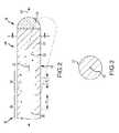
- FIG. 2is a cross-sectional view of a medical device in accordance with one embodiment of the present teachings.
- FIG. 3is a cross-sectional view of the medical device of FIG. 2 taken along lines 3 - 3 .
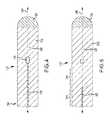
- FIG. 4is a cross-sectional view of a medical device in accordance with another embodiment of the present teachings.
- FIG. 5is a cross-sectional view of a medical device in accordance with another embodiment of the present teachings.
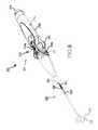
- FIG. 6is an isometric view of a particular medical device—a catheter—in accordance with the present teachings.
- FIG. 7is a schematic illustration of a system for determining the position and orientation of an activation site of a medical operational element of a medical catheter, constructed and operative in accordance with another embodiment of the disclosed technique.
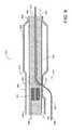
- FIG. 8is a schematic illustration of a longitudinal cross section of the distal end of a medical catheter of the rapid-exchange type, constructed and operative in accordance with a further embodiment of the disclosed technique.
- FIG. 1illustrates a medical device position and navigation system 10 .
- System 10is provided to determine the position of a medical device 12 within a body 14 and to allow a clinician to navigate device 12 within body 14 .
- System 10is conventional in the art and includes a field generator 16 , an electronic control unit 18 and a display 20 .
- Filed generator 16is provided to generate electric and/or magnetic fields for the purpose of inducting changes in current and voltage on position sensors on medical device 12 .
- field generator 16is a magnetic field generator such as that sold under the trademark “gMPS” by Mediguide, Ltd.
- the generatormay include, for example, three orthogonally arranged coils, arranged to create a magnetic field within body 14 and to control the strength, orientation and frequency of the field.
- the magnetic field generatormay be located above or below the patient (e.g., under a patient table) or in another appropriate location.
- the field generator 16may comprise an electric field generator as in the system sold under the trademark “ENSITE NAVX” by St. Jude Medical, Inc.
- the systemincludes three pairs of patch electrodes that are placed on opposed surfaces of the body (e.g., chest and back, left and right sides of the thorax, and neck and leg) and form generally orthogonal x, y, and z axes as well as a reference electrode that is typically placed near the stomach and provides a reference value and acts as the origin of the coordinate system for the navigation system.
- Magnetic fieldsare generated by the coils of the magnetic field generator or sinusoidal currents are driven through each pair of patch electrodes in the electric field generator and current or voltage measurements for one or more position sensors associated with the medical device 12 are obtained.
- the measured currents or voltagesare proportional to the distance of the sensors from the coils or patch electrodes thereby allowing a position of the sensors within the coordinate system of the navigation system 10 to be determined.
- ECU 18is provided to determine a position of the sensors within a coordinate system of the position and navigation system 10 responsive to signals generated by position sensors on device 12 .
- ECU 18is further provided to generate an indication of the position and orientation on display 20 by, for example, retrieving images of a region of interest from an image database having the same position and orientation coordinates within the coordinate system of system 10 and superimposing a representation of device 12 on the image at the detected position and orientation within the image.
- ECU 18may also provide operational control over device 12 .
- ECU 18may comprise a programmable microprocessor or microcontroller or may comprise an application specific integrated circuit (ASIC).
- ASICapplication specific integrated circuit
- ECU 18may include a central processing unit (CPU) and an input/output (I/O) interface through which ECU 18 may receive a plurality of input signals including signals generated by device 12 (and particularly the position sensors on device 12 ) and generate a plurality of output signals including those used to control and/or provide data to device 12 and display 20 .
- CPUcentral processing unit
- I/Oinput/output
- Display 20is provided to convey information to a clinician to assist in diagnosis and treatment.
- Display 20may comprise a conventional computer monitor or other display device.
- Display 20presents a graphical user interface (GUI) to the physician.
- GUIgraphical user interface
- the GUImay include a variety of information including, for example, images of a region of interest in body 14 , electrophysiological data, graphs illustrating voltage levels over time for various sensors and images of device 12 .
- one exemplary medical device 12comprises a catheter 300 .
- Catheter 300includes an elongate deformable member 302 and an ergonomically shaped actuation handle 304 coupled to a proximal end 308 of member 302 .
- Handle 304is adapted to control the deflection of a deflectable distal end 310 of member 302 .
- Handle 304can include a first actuator 312 , upper and lower buttons 314 a , 314 b of a second actuator 314 , upper and lower grip portions 316 a , 316 b , an electrical plug 318 at the proximal end of the handle 304 , and a strain relief 320 at the distal end of the handle 304 .
- the upper and lower grip portions 316 a , 316 bdefine a space 322 that extends laterally through the grip portions 316 a , 316 b .
- the first actuator 312is pivotally coupled to the grip portions 316 a , 316 b and resides in the space 322 .
- the first actuator 312may pivotally displace laterally relative to the grip portions 316 a , 316 b through the space 322 . Such pivotal displacement of the first actuator 312 allows a user to bi-directionally deflect the distal end 310 of the member 302 .
- the upper and lower buttons 314 a , 314 b of the second actuatorare slideably coupled to their respective grip portions 316 a , 316 b in such a manner that they may slideably displace along their respective grip portions 316 a , 316 b in a direction that is generally parallel to the longitudinal axis of the handle 304 .
- Such slideable displacement of the buttons 314 a , 314 b of the second actuator 314allows a user to deflect the distal end 310 of member 302 in a third direction. For example, as indicated in FIG.
- the first actuator 312causes the distal end 310 to deflect bi-directionally right or left, and the buttons 314 a , 314 b of the second actuator 314 cause the distal end 314 to increase or decrease the diameter of its loop or lariat.
- the actuation wires 324 coupled to actuators 312 , 314can be any of the actuation wire types known in the art and may comprise pull or tension wires.
- the actuation wires 324can be formed from a super elastic Nitinol wire or another suitable material and may be housed within a compression coil 326 in a proximal portion of member 302 .
- the distal end 310 of member 302can include a plurality of spaced position sensors 328 .
- Each sensor 328is connected to conductor that extends to the electrical plug 318 through member 302 , the strain relief 320 , and the handle 304 .
- the electrical plug 318is adapted to be connected to a device, such as a recording, monitoring, or ablation device.
- Device 12may comprise, for example, a catheter such as an electrophysiology (EP) mapping catheter, an ablation catheter or an intracardiac electrocardiography (ICE) catheter.
- Device 12may include an elongate, deformable member 22 , a medical operational element 24 , a position sensor 26 , and a conductor 28 .
- Portions of member 22may also be made from materials having different durometers (e.g., a portion made having a relatively hard durometer in a proximal portion and a relatively soft durometer in a distal portion).
- Member 22may be generally circular in cross-section and defines one or more lumens configured to house and/or transport electrical conductors 28 , fluids, guidewires and surgical tools.
- Member 22may be introduced into a blood vessel or other structure within the body through a conventional introducer sheath or another tubular body through which member 22 may be moved longitudinally. Member 22 may then be steered or guided through the body to a desired location with guide wires or other means known in the art.
- proximal end 30refers to a direction toward the end of the catheter near the clinician, and “distal” refers to a direction away from the clinician and (generally) inside the body of a patient).
- Element 24is provided to perform an operation resulting in the diagnosis or treatment of tissue in body 14 .
- Element 24is disposed at distal end 32 of member 22 .
- Element 24may comprise any of a wide variety of conventional diagnostic and/or treatment instruments including those used to modify characteristics of tissues, diagnose tissues or generate images of tissues, including tissues found in body lumens.
- element 24may be used to vascularize a lumen, sever a portion of the lumen or plaque buildup on the lumen, provide a suture to a lumen or increase the size of the lumen (e.g., by a balloon, self expanding stent, a stent made of a shape memory alloy, or a balloon expanding stent) and maintain the increased diameter by implanting a stent and element 24 may therefore comprise a balloon, stent, or balloon expanding stent, for example.
- Element 24may be used to deliver substances to the lumen such as a pharmacological substance.
- Element 24may be used to create tissue necrosis by delivering ablation energy such as ultrasound energy, electromagnetic energy (e.g., radio frequency or lasers) or thermal energy (heat or cryo-ablation) and may therefore comprise a transducer, electrode, laser, or fluid delivery port or valve for example. Element 24 may also be used to deploy a device near a selected tissue such as a valve, marker or sensor. In the illustrated embodiment, element 24 is shown distal to sensor 26 at the distal tip of member 22 . It should be understood, however, that the relative positions of element 24 and sensor 26 could vary. For example, element 24 could alternatively be radially aligned with sensor 26 where element 24 comprises a balloon, for example.
- ablation energysuch as ultrasound energy, electromagnetic energy (e.g., radio frequency or lasers) or thermal energy (heat or cryo-ablation) and may therefore comprise a transducer, electrode, laser, or fluid delivery port or valve for example.
- Element 24may also be used to deploy a device near a selected tissue such as
- Position sensor 26generates a position signal indicative of the position of sensor 26 , and therefore device 12 , within body 14 .
- Sensor 26is conventional in the art.
- sensor 26comprises a coil suitable for use with a position and navigation system 10 employing magnetic fields. As sensor 26 moves within body 14 , and within the generated magnetic field, the current output of sensor 26 changes thereby indicating the location of sensor 26 within the magnetic field and with the coordinate system established by system 10 .
- Sensor 26may be wound about member 22 at or near distal end 32 and may be embedded within member 22 such that sensor 26 is insulated by member 22 . Alternatively, sensor 26 could be embedded within member 22 laterally of the center of member 22 and not wound about member 22 . Further, alternatively, sensor 26 could be external to member 22 .
- Sensor 26may also have appropriate insulation and/or shielding (e.g., a conductive foil or wire mesh) to cancel potential interferences from other devices near body 14 . It should be understood that sensor 26 may take other forms other than the form illustrated in FIG. 2 . Sensor 26 may, for example, comprise any conventional position sensors for detecting changes in magnetic fields including Hall effect sensors, magnetoresistive sensors and sensors made from magnetorestrictive materials and piezoelectric materials and the like. Sensor 26 may also, for example, comprise electrodes in systems employing electric fields to identify the position and orientation of sensors 26 . Sensors 26 communicate position signals to ECU 18 through a conventional interface (not shown).
- a conventional interfacenot shown.
- Conductors 28are provided to transmit signals between ECU 18 and element 24 and between ECU 18 and sensors 26 .
- Conductors 28may comprise wires made from typical electrical conductors such as copper, gold or silver and the like or cables.
- Conductors 28extend from elements 24 and sensors 26 to a point proximal to elements 24 and sensors 26 such as proximal end 30 of member 22 .
- Conductors 28are connected to elements 24 and sensors 26 at connection nodes such as node 34 .
- Conductors 28may be connected to elements 24 and sensors 26 directly through soldering or conductive adhesives or indirectly through a connector such as a flexible printed circuit board or wiring pad.
- Conductors 28may extend to a connection interface at proximal end 30 of member 22 such that signals can be transmitted via another conductor to ECU 18 .
- conductors 28may terminate at a transmitter (not shown) within device 12 such that the information conveyed by conductors 28 is transmitted wirelessly to a corresponding receiver in system 10 connected to ECU 18 .
- Conductors 28may be wound about member 22 .
- Conductors 28may be embedded within member 22 such that substantially the entire length of conductors 28 is surrounded or enclosed by the material forming member 22 and insulated by the material forming member 22 .
- Conductors 28may additionally be coated with a protective coating or coatings that provides electrical insulation and/or or electrical shielding as well as mechanical protection to conductors 28 .
- Conductors 28may alternatively be disposed within grooves formed in a radially outer surface of member 22 by a laser, mechanical engraving, chemical etching, molding, injection, extrusion or similar processes and covered with a protective coating or coatings to provide electrical insulation and/or electrical shielding as well as mechanical protection and to couple conductors 28 to the radially outer surface of member 22 .
- Multiple conductors 28 to elements 24 or sensors 26may be arranged in twisted pairs or coaxially as is known in the art.
- the movementmay be anticipated due to changes in the structure of member 22 by, for example, the termination of a compression coil, durometer changes in the member 22 , pull ring locations, cross-sectional changes, or the like.
- the change in winding pitch for conductor 28is located to work with these decision elements. Accordingly, the change in winding pitch may occur at the termination of a compression coil, the termination of a shape memory wire or other stiffener in member 22 or at a point at which the durometer of member 22 changes.
- the distal end 32 of member 22may deflect from a straight line position relative to the rest of member 22 (i.e., be bent such that the distal tip of member 22 is drawn closer to the proximal end 30 of member 22 ) as shown in broken line in FIG. 2 in order to locate element 24 at an appropriate position and orientation relative to tissues in body 14 and/or to guide member 22 through body 14 .
- conductor 28will experience different compression and tension forces on different portions of conductor 28 .
- Conductor 28may be wound with a smaller winding pitch P 2 proximate distal end 32 to reduce these compression and tension forces.
- Conductor 28may be wound with a greater winding pitch P 1 nearer to proximal end 30 where conductor 28 is not subject to the same mechanical stress. In this manner, the overall mechanical stress on conductor 28 is reduced. Further, various mechanical properties of member 22 may be improved including the increased pushability and traceability of member 22 (i.e., reducing the tendency of member 22 to buckle when pushed within the body lumen and increasing the ability of the member 22 to follow the vessel path), increased elasticity of member 22 (i.e., an increase in the tendency of member 22 to return to the original shape, after being deformed), increased modulus of elasticity of member 22 (i.e., an increase in the mechanical stress in either compression or tension, which is required to deform member 22 by a certain amount), increased coefficient of rigidity of member 22 (i.e., an increase in the mechanical shear stress which is required to twist member 22 by a certain angle), affecting the flexibility or resilience of member 22 , and the like.
- conductor 28may be connected to a position sensor 26 at a connection node 34 that is disposed along a neutral axis 40 of member 22 .
- Axis 40is an axis along which there is no longitudinal stress or strain as member 22 is bent. For example, as distal end 32 of member 22 deflects from a straight line position as shown in broken line in FIG. 2 , portions of member 22 on one side 42 of neutral axis 40 will be in a state of compression as the length of such portions is shortened whereas the portions of member 22 on the other side 44 of axis 40 will be in a state of tension as the length of such portions is increased. The length of neutral axis 40 , however, will remain unchanged and is not subject to compression or tension. Because connection node 34 is located along neutral axis 40 , connection node 34 is also not subjected to compression and tension forces and is less likely to be damaged. Referring to FIG. 3 , axis 40 may be located at the geometric centroid of member 22 .
- Device 112may include a tubular deformable member 122 , a medical operational element 124 , and a position sensor 126 , and a conductor 128 .
- Member 122 , element 124 , and sensor 16may be substantially similar to member 22 , element 24 , and sensor 26 , discussed hereinabove.
- Conductor 128may also be substantially similar to conductor 28 discussed hereinabove. As opposed to being wound about member 122 , however, conductor 128 may be coincident with neutral axis 140 .
- Conductor 128may extend from proximal end 130 to connection node 134 and may be coincident with neutral axis 140 along the entire length of conductor 128 . In this manner, conductor 128 is not subject to compression and tension forces resulting from movement of member 122 .
- Device 212may include a tubular deformable member 222 , a medical operational element 224 , and a position sensor 226 , and a conductor 228 .
- Member 222 , element 224 , and sensor 226may be substantially similar to member 22 , element 24 , and sensor 26 , discussed hereinabove.
- Conductor 228may also be substantially similar to conductor 28 discussed hereinabove.
- a portion 246 of a conductor 228may extend along neutral axis 240 while another portion 248 of conductor 228 is wound about member 222 .
- Portion 248may again have varying winding pitches along different portions of member 222 for the purpose discussed hereinabove.
- FIG. 7is a schematic illustration of a system for determining the position and orientation of an activation site of a medical operational element of a medical catheter, generally referenced 146 , constructed and operative in accordance with another embodiment of the disclosed technique.
- System 146includes a medical catheter 148 and an MPS (medical positioning system) 150 .
- FIG. 7illustrates the distal portion of medical catheter 148 , which is typically about 20 cm long.
- Medical catheter 148includes an elongated member 152 , a medical operational element 154 , an electromagnetic field detector 156 , a wiring 158 and a transmitter 160 .
- Elongated member 152includes a guidewire lumen 162 .
- MPS 150includes a processor 164 , a transmitter 166 , an image database 168 , a display 170 , a detector interface 172 and a receiver 174 .
- Wiring 158is embedded within elongated member 152 .
- Medical operational element 154 and electromagnetic field detector 156are located at a distal end 176 of medical catheter 148 .
- Electromagnetic field detector 156is embedded within elongated member 152 , and encompasses guidewire lumen 162 .
- Transmitter 160is embedded within elongated member 152 and located proximal to distal end 176 . Alternatively, the transmitter can be located at a fluid manifold located at a proximal end of catheter 148 , or anywhere along elongated member 152 or external thereto.
- One end of wiring 158is coupled with electromagnetic field detector 156 and the other end thereof is coupled with transmitter 160 .
- the length of wiring 158is much shorter than that of elongated member 152 , such that wiring 158 occupies a relatively short section of the distal portion of elongated member 152 (usually about 20 cm).
- Processor 164is coupled with transmitter 166 , image database 168 , display 170 and with detector interface 172 .
- Receiver 174is coupled with detector interface 172 .
- Transmitter 166transmits an electromagnetic wave which is received by electromagnetic field detector 156 and electromagnetic field detector 156 sends a signal respective of the position and orientation of distal end 176 to transmitter 160 , via wiring 158 .
- Transmitter 160transmits this signal to receiver 174 and processor 164 determines the position and orientation of distal end 176 , according to a signal received from detector interface 172 .
- wiring 158modifies the mechanical properties of the distal portion of elongated member 152 , such as pushability and trackability.
- the electromagnetic field detectorcan be located external to the elongated member.
- the wiringcan be wound around the elongated member.
- the transmittercan be located external to the elongated member.
- medical catheter 148can be of over-the-wire type, as well as rapid exchange type.
- FIG. 8is a schematic illustration of a longitudinal cross section of the distal end of a medical catheter of the rapid-exchange type, generally referenced 490 , constructed and operative in accordance with a further embodiment of the disclosed technique.
- Rapid-exchange catheteris also known in the art as Single Operator Exchange (SOE).
- Medical catheter 490includes an elongated member 492 , an electromagnetic field detector 494 , a wiring 496 and a medical operational element 498 .
- Medical catheter 490is a balloon type catheter. Therefore, medical operational element 498 includes a tube portion 500 and a balloon portion 502 .
- Electromagnetic field detector 494is made of an electrical conductor (not shown), wound around a core 504 .
- Core 504is made of a material whose permeability is substantially greater than that of the air.
- core 504can be made of a ferromagnetic material (e.g., ferrite, iron, Mu-metal, superalloy, soft ferrite), and the like, as well as a paramagnetic material.
- Electromagnetic field detector 494is embedded within elongated member 492 .
- Wiring 496is embedded within elongated member 492 in a manner previously described herein above.
- Distal ends (not shown) of wiring 496are coupled with two ends (not shown) of electromagnetic field detector 494 .
- Proximal ends (not shown) of wiring 496are coupled with an MPS.
- a distal end 506 of balloon portion 502is coupled with a distal end 508 of elongated member 492 .
- Elongated member 492includes a guidewire lumen 510 , whose entrance 512 is located at distal end 508 and whose exit 514 is located at a side portion 516 of elongated member 492 . Side portion 516 is located at a proximal end 518 of balloon portion 502 . Electromagnetic field detector 494 is located proximal to exit 514 (i.e., adjacent to proximal end 518 ). A concentric fluid lumen 520 , formed between tube portion 500 and an outer wall 522 of elongated member 492 , is coupled with a pressurized fluid source.
- a region of tube portion 500 in the vicinity of side portion 516is coupled with side portion 516 , in order to prevent fluid communication between guidewire lumen 510 and concentric fluid lumen 520 .
- Tube portion 500is perforated at side portion 516 , in order to keep exit 514 open.
- the physicianenters a proximal end 526 of guidewire 524 through entrance 512 , until proximal end 526 of guidewire 524 passes through guidewire lumen 510 and exits guidewire lumen 510 at exit 514 . This mode of operation is known in the art as “rapid-exchange.”
- elongated member 492 proximal to exit 514is solid, it is possible to incorporate core 504 with electromagnetic field detector 494 . Furthermore, since core 504 is made of a ferromagnetic material, electromagnetic field detector 494 is more sensitive to the electromagnetic field generated by a transmitter.
- a medical device for diagnosis or treatment of a tissue within a body in accordance with the present teachingsrepresents an improvement relative to conventional devices.
- mechanical stress on the conductors and connection nodesare reduced.
- the reliability and life of devicesare improved.
- joinder referencesare to be construed broadly and may include intermediate members between a connection of elements and relative movement between elements. As such, joinder references do not necessarily infer that two elements are directly connected and in fixed relation to each other. It is intended that all matter contained in the above description or shown in the accompanying drawings shall be interpreted as illustrative only and not as limiting. Changes in detail or structure may be made without departing from the invention as defined in the appended claims.
Landscapes
- Health & Medical Sciences (AREA)
- Life Sciences & Earth Sciences (AREA)
- Engineering & Computer Science (AREA)
- Surgery (AREA)
- Animal Behavior & Ethology (AREA)
- General Health & Medical Sciences (AREA)
- Biomedical Technology (AREA)
- Heart & Thoracic Surgery (AREA)
- Veterinary Medicine (AREA)
- Public Health (AREA)
- Molecular Biology (AREA)
- Medical Informatics (AREA)
- Nuclear Medicine, Radiotherapy & Molecular Imaging (AREA)
- Biophysics (AREA)
- Vascular Medicine (AREA)
- Robotics (AREA)
- Human Computer Interaction (AREA)
- Physics & Mathematics (AREA)
- Pathology (AREA)
- Pulmonology (AREA)
- Anesthesiology (AREA)
- Hematology (AREA)
- Media Introduction/Drainage Providing Device (AREA)
Abstract
Description
Claims (19)
Priority Applications (1)
| Application Number | Priority Date | Filing Date | Title |
|---|---|---|---|
| US14/808,892US10493235B2 (en) | 2002-11-18 | 2015-07-24 | Reducing mechanical stress on conductors and connection points in a position determinable interventional medical device |
Applications Claiming Priority (5)
| Application Number | Priority Date | Filing Date | Title |
|---|---|---|---|
| US29835802A | 2002-11-18 | 2002-11-18 | |
| US10/408,156US7881769B2 (en) | 2002-11-18 | 2003-04-07 | Method and system for mounting an MPS sensor on a catheter |
| US12/982,592US8862204B2 (en) | 2002-11-18 | 2010-12-30 | Reducing mechanical stress on conductors and connection points in a position determinable interventional medical device |
| US14/485,318US9375549B2 (en) | 2002-11-18 | 2014-09-12 | Reducing mechanical stress on conductors and connection points in a position determinable interventional medical device |
| US14/808,892US10493235B2 (en) | 2002-11-18 | 2015-07-24 | Reducing mechanical stress on conductors and connection points in a position determinable interventional medical device |
Related Parent Applications (1)
| Application Number | Title | Priority Date | Filing Date |
|---|---|---|---|
| US14/485,318DivisionUS9375549B2 (en) | 2002-11-18 | 2014-09-12 | Reducing mechanical stress on conductors and connection points in a position determinable interventional medical device |
Publications (2)
| Publication Number | Publication Date |
|---|---|
| US20160022958A1 US20160022958A1 (en) | 2016-01-28 |
| US10493235B2true US10493235B2 (en) | 2019-12-03 |
Family
ID=44011827
Family Applications (3)
| Application Number | Title | Priority Date | Filing Date |
|---|---|---|---|
| US12/982,592Expired - LifetimeUS8862204B2 (en) | 2002-11-18 | 2010-12-30 | Reducing mechanical stress on conductors and connection points in a position determinable interventional medical device |
| US14/485,318Expired - Fee RelatedUS9375549B2 (en) | 2002-11-18 | 2014-09-12 | Reducing mechanical stress on conductors and connection points in a position determinable interventional medical device |
| US14/808,892Expired - Fee RelatedUS10493235B2 (en) | 2002-11-18 | 2015-07-24 | Reducing mechanical stress on conductors and connection points in a position determinable interventional medical device |
Family Applications Before (2)
| Application Number | Title | Priority Date | Filing Date |
|---|---|---|---|
| US12/982,592Expired - LifetimeUS8862204B2 (en) | 2002-11-18 | 2010-12-30 | Reducing mechanical stress on conductors and connection points in a position determinable interventional medical device |
| US14/485,318Expired - Fee RelatedUS9375549B2 (en) | 2002-11-18 | 2014-09-12 | Reducing mechanical stress on conductors and connection points in a position determinable interventional medical device |
Country Status (1)
| Country | Link |
|---|---|
| US (3) | US8862204B2 (en) |
Families Citing this family (27)
| Publication number | Priority date | Publication date | Assignee | Title |
|---|---|---|---|---|
| US8862204B2 (en)* | 2002-11-18 | 2014-10-14 | Mediguide Ltd. | Reducing mechanical stress on conductors and connection points in a position determinable interventional medical device |
| US9226689B2 (en)* | 2009-03-10 | 2016-01-05 | Medtronic Xomed, Inc. | Flexible circuit sheet |
| US9226688B2 (en) | 2009-03-10 | 2016-01-05 | Medtronic Xomed, Inc. | Flexible circuit assemblies |
| US8504139B2 (en) | 2009-03-10 | 2013-08-06 | Medtronic Xomed, Inc. | Navigating a surgical instrument |
| KR101478264B1 (en) | 2010-04-30 | 2014-12-31 | 메드트로닉 좀드 인코퍼레이티드 | Navigated malleable surgical instrument |
| US9974501B2 (en) | 2011-01-28 | 2018-05-22 | Medtronic Navigation, Inc. | Method and apparatus for image-based navigation |
| US10617374B2 (en) | 2011-01-28 | 2020-04-14 | Medtronic Navigation, Inc. | Method and apparatus for image-based navigation |
| US10492868B2 (en) | 2011-01-28 | 2019-12-03 | Medtronic Navigation, Inc. | Method and apparatus for image-based navigation |
| US9750486B2 (en) | 2011-10-25 | 2017-09-05 | Medtronic Navigation, Inc. | Trackable biopsy needle |
| EP2916759B1 (en)* | 2012-11-09 | 2018-12-26 | Boston Scientific Scimed, Inc. | Surgical laser tool |
| US10278729B2 (en) | 2013-04-26 | 2019-05-07 | Medtronic Xomed, Inc. | Medical device and its construction |
| WO2015143421A1 (en)* | 2014-03-21 | 2015-09-24 | St. Jude Medical, Cardiology Division, Inc. | Magnetic localization of a medical device |
| US9754367B2 (en) | 2014-07-02 | 2017-09-05 | Covidien Lp | Trachea marking |
| AU2015283946B2 (en) | 2014-07-02 | 2019-09-12 | Covidien Lp | Real-time automatic registration feedback |
| US9603668B2 (en) | 2014-07-02 | 2017-03-28 | Covidien Lp | Dynamic 3D lung map view for tool navigation inside the lung |
| US20160000414A1 (en) | 2014-07-02 | 2016-01-07 | Covidien Lp | Methods for marking biopsy location |
| US9770216B2 (en) | 2014-07-02 | 2017-09-26 | Covidien Lp | System and method for navigating within the lung |
| CN106232010B (en) | 2014-07-02 | 2020-03-31 | 柯惠有限合伙公司 | System and method for detecting trachea |
| CN106659453B (en) | 2014-07-02 | 2020-05-26 | 柯惠有限合伙公司 | System and method for segmenting lungs |
| US11367947B2 (en)* | 2015-03-16 | 2022-06-21 | St. Jude Medical International Holding S.á r.l. | Field concentrating antennas for magnetic position sensors |
| US10986990B2 (en) | 2015-09-24 | 2021-04-27 | Covidien Lp | Marker placement |
| US10709352B2 (en) | 2015-10-27 | 2020-07-14 | Covidien Lp | Method of using lung airway carina locations to improve ENB registration |
| US12011549B2 (en)* | 2017-01-19 | 2024-06-18 | St. Jude Medical, Cardiology Division, Inc. | Sheath visualization |
| US11224392B2 (en) | 2018-02-01 | 2022-01-18 | Covidien Lp | Mapping disease spread |
| US20190357984A1 (en)* | 2018-05-24 | 2019-11-28 | Biosense Webster (Israel) Ltd. | Position Sensor on Brain-Clot Removal Sheath and Location Pad Collar |
| US12089902B2 (en) | 2019-07-30 | 2024-09-17 | Coviden Lp | Cone beam and 3D fluoroscope lung navigation |
| US12011233B2 (en) | 2019-11-26 | 2024-06-18 | Arizona Board Of Regents On Behalf Of Arizona State University | System and method for determining position of a steerable assembly within tissue of an animal body |
Citations (49)
| Publication number | Priority date | Publication date | Assignee | Title |
|---|---|---|---|---|
| JPH05177001A (en) | 1991-12-26 | 1993-07-20 | Kanegafuchi Chem Ind Co Ltd | Expanding catheter |
| JPH05285222A (en) | 1992-04-13 | 1993-11-02 | Inter Noba Kk | Balloon catheter and manufacture thereof |
| JPH06142106A (en) | 1992-06-05 | 1994-05-24 | Cardiac Pathways Corp | Intracardiac mapping and ablation device and method utilizing separately controlled ablation catheters |
| US5489271A (en) | 1994-03-29 | 1996-02-06 | Boston Scientific Corporation | Convertible catheter |
| WO1996005768A1 (en) | 1994-08-19 | 1996-02-29 | Biosense, Inc. | Medical diagnosis, treatment and imaging systems |
| JPH08155031A (en) | 1994-12-06 | 1996-06-18 | Hitachi Medical Corp | Catheter installed with cable and catheter with functional parts using the same |
| US5588432A (en) | 1988-03-21 | 1996-12-31 | Boston Scientific Corporation | Catheters for imaging, sensing electrical potentials, and ablating tissue |
| US5646525A (en) | 1992-06-16 | 1997-07-08 | Elbit Ltd. | Three dimensional tracking system employing a rotating field |
| WO1997029684A1 (en) | 1996-02-15 | 1997-08-21 | Biosense, Inc. | Catheter with lumen |
| WO1998010303A1 (en) | 1996-09-02 | 1998-03-12 | Philips Electronics N.V. | Invasive device for use in a magnetic resonance imaging apparatus |
| US5830222A (en) | 1995-10-13 | 1998-11-03 | Transvascular, Inc. | Device, system and method for intersititial transvascular intervention |
| US5840024A (en)* | 1993-10-18 | 1998-11-24 | Olympus Optical Co., Ltd. | Endoscope form detecting apparatus in which coil is fixedly mounted by insulating member so that form is not deformed within endoscope |
| WO1998052637A1 (en) | 1997-05-23 | 1998-11-26 | Biosense, Inc. | Catheter with oblique lumen |
| US5873835A (en) | 1993-04-29 | 1999-02-23 | Scimed Life Systems, Inc. | Intravascular pressure and flow sensor |
| US5897529A (en) | 1997-09-05 | 1999-04-27 | Cordis Webster, Inc. | Steerable deflectable catheter having improved flexibility |
| US5916241A (en) | 1992-03-06 | 1999-06-29 | Urologix, Inc. | Device and method for asymmetrical thermal therapy with helical dipole microwave antenna |
| JPH11188112A (en) | 1997-08-11 | 1999-07-13 | Advanced Cardeovascular Syst Inc | Protective device for sheath and method therefor |
| US5928248A (en) | 1997-02-14 | 1999-07-27 | Biosense, Inc. | Guided deployment of stents |
| WO1999039624A1 (en) | 1998-02-05 | 1999-08-12 | Biosense Inc. | Intracardiac drug delivery |
| WO1999059479A1 (en) | 1998-05-19 | 1999-11-25 | Regents Of The University Of Minnesota | Device for endovascular treatment |
| US6004269A (en)* | 1993-07-01 | 1999-12-21 | Boston Scientific Corporation | Catheters for imaging, sensing electrical potentials, and ablating tissue |
| WO2000010456A1 (en) | 1998-08-02 | 2000-03-02 | Super Dimension Ltd. | Intrabody navigation system for medical applications |
| US6035856A (en) | 1997-03-06 | 2000-03-14 | Scimed Life Systems | Percutaneous bypass with branching vessel |
| WO2000016684A1 (en) | 1998-09-24 | 2000-03-30 | Super Dimension Ltd. | System and method for determining the location of a catheter during an intra-body medical procedure |
| US6179811B1 (en) | 1997-11-25 | 2001-01-30 | Medtronic, Inc. | Imbedded marker and flexible guide wire shaft |
| US6203493B1 (en)* | 1996-02-15 | 2001-03-20 | Biosense, Inc. | Attachment with one or more sensors for precise position determination of endoscopes |
| US6233476B1 (en) | 1999-05-18 | 2001-05-15 | Mediguide Ltd. | Medical positioning system |
| US6231516B1 (en) | 1997-10-14 | 2001-05-15 | Vacusense, Inc. | Endoluminal implant with therapeutic and diagnostic capability |
| US6251107B1 (en) | 1998-06-25 | 2001-06-26 | Cardima, Inc. | Ep catheter |
| US6298259B1 (en) | 1998-10-16 | 2001-10-02 | Univ Minnesota | Combined magnetic resonance imaging and magnetic stereotaxis surgical apparatus and processes |
| JP2002035132A (en) | 2000-07-21 | 2002-02-05 | Mitsubishi Cable Ind Ltd | Method for manufacturing flexible tube having electric wiring and flexible tube having electric wiring |
| US20020016589A1 (en) | 1997-07-21 | 2002-02-07 | Daig Corporation | Ablation catheter |
| US20020032380A1 (en)* | 1996-02-15 | 2002-03-14 | David E. Acker | Medical probes with field transducers |
| US20020099364A1 (en) | 1997-02-27 | 2002-07-25 | Cryocath Technologies, Inc. | Apparatus and method for performing a treatment on a selected tissue region |
| US6427079B1 (en) | 1999-08-09 | 2002-07-30 | Cormedica Corporation | Position and orientation measuring with magnetic fields |
| US20020128537A1 (en) | 2001-03-12 | 2002-09-12 | Olympus Optical Co., Ltd. | Endoscope |
| US20020143371A1 (en) | 2001-03-30 | 2002-10-03 | Balczewski Ron A. | Implantable medical device with temperature measuring and storing capability |
| US20020143317A1 (en) | 2001-03-30 | 2002-10-03 | Glossop Neil David | Device and method for registering a position sensor in an anatomical body |
| US6474341B1 (en)* | 1999-10-28 | 2002-11-05 | Surgical Navigation Technologies, Inc. | Surgical communication and power system |
| US6498944B1 (en)* | 1996-02-01 | 2002-12-24 | Biosense, Inc. | Intrabody measurement |
| US6509521B1 (en) | 2000-11-10 | 2003-01-21 | Scimed Life Systems, Inc. | X-ray catheter with coaxial conductor |
| US6618612B1 (en) | 1996-02-15 | 2003-09-09 | Biosense, Inc. | Independently positionable transducers for location system |
| US6690963B2 (en) | 1995-01-24 | 2004-02-10 | Biosense, Inc. | System for determining the location and orientation of an invasive medical instrument |
| US6689049B1 (en) | 1999-06-07 | 2004-02-10 | Olympus Optical Co., Ltd. | Endoscope |
| US20040097804A1 (en) | 2002-11-18 | 2004-05-20 | Mediguide Ltd. | Method and system for mounting an MPS sensor on a catheter |
| US7001383B2 (en)* | 2002-10-21 | 2006-02-21 | Biosense, Inc. | Real-time monitoring and mapping of ablation lesion formation in the heart |
| US20070225641A1 (en) | 2005-06-28 | 2007-09-27 | Clint Schneider | Auto lock for catheter handle |
| US8862204B2 (en)* | 2002-11-18 | 2014-10-14 | Mediguide Ltd. | Reducing mechanical stress on conductors and connection points in a position determinable interventional medical device |
| EP2679149B1 (en) | 2012-06-25 | 2015-04-08 | Biosense Webster (Israel), Ltd. | Probe with a distal sensor and with a proximal cable connected to a wireless tranceiver |
Family Cites Families (1)
| Publication number | Priority date | Publication date | Assignee | Title |
|---|---|---|---|---|
| US6086725A (en)* | 1998-04-02 | 2000-07-11 | Applied Materials, Inc. | Target for use in magnetron sputtering of nickel for forming metallization films having consistent uniformity through life |
- 2010
- 2010-12-30USUS12/982,592patent/US8862204B2/ennot_activeExpired - Lifetime
- 2014
- 2014-09-12USUS14/485,318patent/US9375549B2/ennot_activeExpired - Fee Related
- 2015
- 2015-07-24USUS14/808,892patent/US10493235B2/ennot_activeExpired - Fee Related
Patent Citations (52)
| Publication number | Priority date | Publication date | Assignee | Title |
|---|---|---|---|---|
| US5588432A (en) | 1988-03-21 | 1996-12-31 | Boston Scientific Corporation | Catheters for imaging, sensing electrical potentials, and ablating tissue |
| JPH05177001A (en) | 1991-12-26 | 1993-07-20 | Kanegafuchi Chem Ind Co Ltd | Expanding catheter |
| US5916241A (en) | 1992-03-06 | 1999-06-29 | Urologix, Inc. | Device and method for asymmetrical thermal therapy with helical dipole microwave antenna |
| JPH05285222A (en) | 1992-04-13 | 1993-11-02 | Inter Noba Kk | Balloon catheter and manufacture thereof |
| JPH06142106A (en) | 1992-06-05 | 1994-05-24 | Cardiac Pathways Corp | Intracardiac mapping and ablation device and method utilizing separately controlled ablation catheters |
| US5646525A (en) | 1992-06-16 | 1997-07-08 | Elbit Ltd. | Three dimensional tracking system employing a rotating field |
| US5873835A (en) | 1993-04-29 | 1999-02-23 | Scimed Life Systems, Inc. | Intravascular pressure and flow sensor |
| US6004269A (en)* | 1993-07-01 | 1999-12-21 | Boston Scientific Corporation | Catheters for imaging, sensing electrical potentials, and ablating tissue |
| US5840024A (en)* | 1993-10-18 | 1998-11-24 | Olympus Optical Co., Ltd. | Endoscope form detecting apparatus in which coil is fixedly mounted by insulating member so that form is not deformed within endoscope |
| US5489271A (en) | 1994-03-29 | 1996-02-06 | Boston Scientific Corporation | Convertible catheter |
| WO1996005768A1 (en) | 1994-08-19 | 1996-02-29 | Biosense, Inc. | Medical diagnosis, treatment and imaging systems |
| JPH08155031A (en) | 1994-12-06 | 1996-06-18 | Hitachi Medical Corp | Catheter installed with cable and catheter with functional parts using the same |
| US6690963B2 (en) | 1995-01-24 | 2004-02-10 | Biosense, Inc. | System for determining the location and orientation of an invasive medical instrument |
| US5830222A (en) | 1995-10-13 | 1998-11-03 | Transvascular, Inc. | Device, system and method for intersititial transvascular intervention |
| US6498944B1 (en)* | 1996-02-01 | 2002-12-24 | Biosense, Inc. | Intrabody measurement |
| US20020032380A1 (en)* | 1996-02-15 | 2002-03-14 | David E. Acker | Medical probes with field transducers |
| US6618612B1 (en) | 1996-02-15 | 2003-09-09 | Biosense, Inc. | Independently positionable transducers for location system |
| US6253770B1 (en) | 1996-02-15 | 2001-07-03 | Biosense, Inc. | Catheter with lumen |
| US6203493B1 (en)* | 1996-02-15 | 2001-03-20 | Biosense, Inc. | Attachment with one or more sensors for precise position determination of endoscopes |
| WO1997029684A1 (en) | 1996-02-15 | 1997-08-21 | Biosense, Inc. | Catheter with lumen |
| WO1998010303A1 (en) | 1996-09-02 | 1998-03-12 | Philips Electronics N.V. | Invasive device for use in a magnetic resonance imaging apparatus |
| US5928248A (en) | 1997-02-14 | 1999-07-27 | Biosense, Inc. | Guided deployment of stents |
| US20020099364A1 (en) | 1997-02-27 | 2002-07-25 | Cryocath Technologies, Inc. | Apparatus and method for performing a treatment on a selected tissue region |
| US6035856A (en) | 1997-03-06 | 2000-03-14 | Scimed Life Systems | Percutaneous bypass with branching vessel |
| WO1998052637A1 (en) | 1997-05-23 | 1998-11-26 | Biosense, Inc. | Catheter with oblique lumen |
| US20020016589A1 (en) | 1997-07-21 | 2002-02-07 | Daig Corporation | Ablation catheter |
| JPH11188112A (en) | 1997-08-11 | 1999-07-13 | Advanced Cardeovascular Syst Inc | Protective device for sheath and method therefor |
| US5897529A (en) | 1997-09-05 | 1999-04-27 | Cordis Webster, Inc. | Steerable deflectable catheter having improved flexibility |
| US6231516B1 (en) | 1997-10-14 | 2001-05-15 | Vacusense, Inc. | Endoluminal implant with therapeutic and diagnostic capability |
| US6179811B1 (en) | 1997-11-25 | 2001-01-30 | Medtronic, Inc. | Imbedded marker and flexible guide wire shaft |
| WO1999039624A1 (en) | 1998-02-05 | 1999-08-12 | Biosense Inc. | Intracardiac drug delivery |
| WO1999059479A1 (en) | 1998-05-19 | 1999-11-25 | Regents Of The University Of Minnesota | Device for endovascular treatment |
| US6251107B1 (en) | 1998-06-25 | 2001-06-26 | Cardima, Inc. | Ep catheter |
| WO2000010456A1 (en) | 1998-08-02 | 2000-03-02 | Super Dimension Ltd. | Intrabody navigation system for medical applications |
| WO2000016684A1 (en) | 1998-09-24 | 2000-03-30 | Super Dimension Ltd. | System and method for determining the location of a catheter during an intra-body medical procedure |
| US6298259B1 (en) | 1998-10-16 | 2001-10-02 | Univ Minnesota | Combined magnetic resonance imaging and magnetic stereotaxis surgical apparatus and processes |
| US6233476B1 (en) | 1999-05-18 | 2001-05-15 | Mediguide Ltd. | Medical positioning system |
| US6689049B1 (en) | 1999-06-07 | 2004-02-10 | Olympus Optical Co., Ltd. | Endoscope |
| US6427079B1 (en) | 1999-08-09 | 2002-07-30 | Cormedica Corporation | Position and orientation measuring with magnetic fields |
| US6474341B1 (en)* | 1999-10-28 | 2002-11-05 | Surgical Navigation Technologies, Inc. | Surgical communication and power system |
| JP2002035132A (en) | 2000-07-21 | 2002-02-05 | Mitsubishi Cable Ind Ltd | Method for manufacturing flexible tube having electric wiring and flexible tube having electric wiring |
| US6509521B1 (en) | 2000-11-10 | 2003-01-21 | Scimed Life Systems, Inc. | X-ray catheter with coaxial conductor |
| US20020128537A1 (en) | 2001-03-12 | 2002-09-12 | Olympus Optical Co., Ltd. | Endoscope |
| US20020143317A1 (en) | 2001-03-30 | 2002-10-03 | Glossop Neil David | Device and method for registering a position sensor in an anatomical body |
| US20020143371A1 (en) | 2001-03-30 | 2002-10-03 | Balczewski Ron A. | Implantable medical device with temperature measuring and storing capability |
| US7001383B2 (en)* | 2002-10-21 | 2006-02-21 | Biosense, Inc. | Real-time monitoring and mapping of ablation lesion formation in the heart |
| US20040097804A1 (en) | 2002-11-18 | 2004-05-20 | Mediguide Ltd. | Method and system for mounting an MPS sensor on a catheter |
| US7881769B2 (en)* | 2002-11-18 | 2011-02-01 | Mediguide Ltd. | Method and system for mounting an MPS sensor on a catheter |
| US8862204B2 (en)* | 2002-11-18 | 2014-10-14 | Mediguide Ltd. | Reducing mechanical stress on conductors and connection points in a position determinable interventional medical device |
| US9375549B2 (en)* | 2002-11-18 | 2016-06-28 | Mediguide Ltd. | Reducing mechanical stress on conductors and connection points in a position determinable interventional medical device |
| US20070225641A1 (en) | 2005-06-28 | 2007-09-27 | Clint Schneider | Auto lock for catheter handle |
| EP2679149B1 (en) | 2012-06-25 | 2015-04-08 | Biosense Webster (Israel), Ltd. | Probe with a distal sensor and with a proximal cable connected to a wireless tranceiver |
Non-Patent Citations (3)
| Title |
|---|
| "PTCA with Stent" https://www.bostonscientific.com/common_templates/articleDisplayTemplate.jhtml?task=tskProcedureOverview.jhtml§ionID=4&relid=2,63,64&procedureId=94. |
| International Search Report issued in International (PCT) Patent Application No. PCT/IL03/00940 (dated Feb. 28, 2006). |
| Kern, Morton J., "The Interventional Cardiac Catheterization Handbook," 3rd ed., Mosby-Year Book, Inc. pp. 17-43, 72-74, 80-101, 224-250, 393 and 436 (1999). |
Also Published As
| Publication number | Publication date |
|---|---|
| US9375549B2 (en) | 2016-06-28 |
| US20110118592A1 (en) | 2011-05-19 |
| US20150005625A1 (en) | 2015-01-01 |
| US8862204B2 (en) | 2014-10-14 |
| US20160022958A1 (en) | 2016-01-28 |
Similar Documents
| Publication | Publication Date | Title |
|---|---|---|
| US10493235B2 (en) | Reducing mechanical stress on conductors and connection points in a position determinable interventional medical device | |
| US12171487B2 (en) | Medical device with contact force sensing tip | |
| AU2016200819B2 (en) | Angioplasty guidewire | |
| US20210369132A1 (en) | Intraluminal reference electrode for cardiovascular treatment apparatus | |
| US11051877B2 (en) | Medical device with contact force sensing tip | |
| US20080177175A1 (en) | Esophageal mapping catheter | |
| EP3021748B1 (en) | Magnetic field generator with minimal image occlusion and minimal impact on dimensions in c-arm x-ray environments | |
| US20100160772A1 (en) | Adaptable Image Guided Delivery System | |
| CN103298392A (en) | Medical devices having an electroanatomical system imaging element mounted thereon | |
| EP3681427B1 (en) | Controllable expandable catheter | |
| US9125573B2 (en) | Electrically transparent introducer sheath | |
| CN104271035A (en) | Medical device guidewire with helical cutout and coating | |
| US20240307128A1 (en) | Devices and methods for guide wire placement | |
| EP3389541A1 (en) | System and method of cancellation of source induced errors | |
| US20240415407A1 (en) | System and apparatus for detecting catheters relative to introducers | |
| US20220008011A1 (en) | Printed sensor coil | |
| WO2019234687A2 (en) | Sensing, mapping, and therapy catheter with multiple catheterlets | |
| US20210128230A1 (en) | Catheter including deflectable shaft and methods of assembling same | |
| US11628275B2 (en) | Electronic devices | |
| US20230329577A1 (en) | Magnetic Position Sensor and Cable |
Legal Events
| Date | Code | Title | Description |
|---|---|---|---|
| AS | Assignment | Owner name:MEDIGUIDE LTD., ISRAEL Free format text:ASSIGNMENT OF ASSIGNORS INTEREST;ASSIGNORS:SOBE, LIOR;SELA, RAN;REEL/FRAME:036822/0270 Effective date:20110803 | |
| AS | Assignment | Owner name:ST. JUDE MEDICAL INTERNATIONAL HOLDING S.A R.L., L Free format text:ASSIGNMENT OF ASSIGNORS INTEREST;ASSIGNOR:MEDIGUIDE LTD.;REEL/FRAME:048623/0188 Effective date:20190123 Owner name:ST. JUDE MEDICAL INTERNATIONAL HOLDING S.A R.L., LUXEMBOURG Free format text:ASSIGNMENT OF ASSIGNORS INTEREST;ASSIGNOR:MEDIGUIDE LTD.;REEL/FRAME:048623/0188 Effective date:20190123 | |
| STPP | Information on status: patent application and granting procedure in general | Free format text:NON FINAL ACTION MAILED | |
| STPP | Information on status: patent application and granting procedure in general | Free format text:NOTICE OF ALLOWANCE MAILED -- APPLICATION RECEIVED IN OFFICE OF PUBLICATIONS | |
| STPP | Information on status: patent application and granting procedure in general | Free format text:AWAITING TC RESP., ISSUE FEE NOT PAID | |
| STPP | Information on status: patent application and granting procedure in general | Free format text:NOTICE OF ALLOWANCE MAILED -- APPLICATION RECEIVED IN OFFICE OF PUBLICATIONS | |
| STPP | Information on status: patent application and granting procedure in general | Free format text:PUBLICATIONS -- ISSUE FEE PAYMENT VERIFIED | |
| STCF | Information on status: patent grant | Free format text:PATENTED CASE | |
| FEPP | Fee payment procedure | Free format text:MAINTENANCE FEE REMINDER MAILED (ORIGINAL EVENT CODE: REM.); ENTITY STATUS OF PATENT OWNER: LARGE ENTITY | |
| LAPS | Lapse for failure to pay maintenance fees | Free format text:PATENT EXPIRED FOR FAILURE TO PAY MAINTENANCE FEES (ORIGINAL EVENT CODE: EXP.); ENTITY STATUS OF PATENT OWNER: LARGE ENTITY | |
| STCH | Information on status: patent discontinuation | Free format text:PATENT EXPIRED DUE TO NONPAYMENT OF MAINTENANCE FEES UNDER 37 CFR 1.362 | |
| FP | Lapsed due to failure to pay maintenance fee | Effective date:20231203 |