US10492760B2 - Image guided intravascular therapy catheter utilizing a thin chip multiplexor - Google Patents
Image guided intravascular therapy catheter utilizing a thin chip multiplexorDownload PDFInfo
- Publication number
- US10492760B2 US10492760B2US16/259,740US201916259740AUS10492760B2US 10492760 B2US10492760 B2US 10492760B2US 201916259740 AUS201916259740 AUS 201916259740AUS 10492760 B2US10492760 B2US 10492760B2
- Authority
- US
- United States
- Prior art keywords
- ultrasound
- array
- contacts
- catheter
- elements
- Prior art date
- Legal status (The legal status is an assumption and is not a legal conclusion. Google has not performed a legal analysis and makes no representation as to the accuracy of the status listed.)
- Active
Links
- 238000002560therapeutic procedureMethods0.000titledescription3
- 238000002604ultrasonographyMethods0.000claimsabstractdescription61
- 239000000463materialSubstances0.000claimsdescription16
- 238000001990intravenous administrationMethods0.000claimsdescription12
- 238000002679ablationMethods0.000claimsdescription5
- 238000007674radiofrequency ablationMethods0.000claimsdescription4
- 230000013011matingEffects0.000claimsdescription2
- 230000001681protective effectEffects0.000abstract1
- 238000000034methodMethods0.000description11
- 238000003384imaging methodMethods0.000description7
- 229910000679solderInorganic materials0.000description6
- 238000003780insertionMethods0.000description5
- 230000037431insertionEffects0.000description5
- 210000004204blood vesselAnatomy0.000description4
- 239000004033plasticSubstances0.000description4
- 229920003023plasticPolymers0.000description4
- 239000000853adhesiveSubstances0.000description3
- 230000001070adhesive effectEffects0.000description3
- 230000005540biological transmissionEffects0.000description3
- 229910052738indiumInorganic materials0.000description3
- XUIMIQQOPSSXEZ-UHFFFAOYSA-NSiliconChemical compound[Si]XUIMIQQOPSSXEZ-UHFFFAOYSA-N0.000description2
- 238000007792additionMethods0.000description2
- 210000001367arteryAnatomy0.000description2
- 230000008901benefitEffects0.000description2
- 230000000747cardiac effectEffects0.000description2
- 239000004020conductorSubstances0.000description2
- 238000010586diagramMethods0.000description2
- 230000006870functionEffects0.000description2
- 239000003550markerSubstances0.000description2
- 238000012986modificationMethods0.000description2
- 230000004048modificationEffects0.000description2
- 230000035515penetrationEffects0.000description2
- 229920000642polymerPolymers0.000description2
- 229910052710siliconInorganic materials0.000description2
- 239000010703siliconSubstances0.000description2
- 239000000758substrateSubstances0.000description2
- 229920002994synthetic fiberPolymers0.000description2
- 230000007704transitionEffects0.000description2
- 238000012285ultrasound imagingMethods0.000description2
- 230000002792vascularEffects0.000description2
- 239000004963TorlonSubstances0.000description1
- 229920003997Torlon®Polymers0.000description1
- 230000002745absorbentEffects0.000description1
- 239000002250absorbentSubstances0.000description1
- 230000015572biosynthetic processEffects0.000description1
- 239000008280bloodSubstances0.000description1
- 210000004369bloodAnatomy0.000description1
- 239000000919ceramicSubstances0.000description1
- 238000006243chemical reactionMethods0.000description1
- 238000005094computer simulationMethods0.000description1
- 238000003745diagnosisMethods0.000description1
- 239000007772electrode materialSubstances0.000description1
- 239000000945fillerSubstances0.000description1
- APFVFJFRJDLVQX-UHFFFAOYSA-Nindium atomChemical compound[In]APFVFJFRJDLVQX-UHFFFAOYSA-N0.000description1
- 238000004519manufacturing processMethods0.000description1
- 238000002844meltingMethods0.000description1
- 230000008018meltingEffects0.000description1
- 229920002959polymer blendPolymers0.000description1
- 229920000306polymethylpentenePolymers0.000description1
- 239000011116polymethylpenteneSubstances0.000description1
- 230000008569processEffects0.000description1
- 230000000630rising effectEffects0.000description1
- 239000004065semiconductorSubstances0.000description1
- 229920002379silicone rubberPolymers0.000description1
- 239000004945silicone rubberSubstances0.000description1
- 239000007787solidSubstances0.000description1
- 239000000126substanceSubstances0.000description1
- 230000003746surface roughnessEffects0.000description1
- 230000032258transportEffects0.000description1
Images


Classifications
- A—HUMAN NECESSITIES
- A61—MEDICAL OR VETERINARY SCIENCE; HYGIENE
- A61B—DIAGNOSIS; SURGERY; IDENTIFICATION
- A61B8/00—Diagnosis using ultrasonic, sonic or infrasonic waves
- A61B8/44—Constructional features of the ultrasonic, sonic or infrasonic diagnostic device
- A61B8/4444—Constructional features of the ultrasonic, sonic or infrasonic diagnostic device related to the probe
- A61B8/445—Details of catheter construction
- A—HUMAN NECESSITIES
- A61—MEDICAL OR VETERINARY SCIENCE; HYGIENE
- A61B—DIAGNOSIS; SURGERY; IDENTIFICATION
- A61B18/00—Surgical instruments, devices or methods for transferring non-mechanical forms of energy to or from the body
- A61B18/04—Surgical instruments, devices or methods for transferring non-mechanical forms of energy to or from the body by heating
- A61B18/12—Surgical instruments, devices or methods for transferring non-mechanical forms of energy to or from the body by heating by passing a current through the tissue to be heated, e.g. high-frequency current
- A61B18/14—Probes or electrodes therefor
- A61B18/1492—Probes or electrodes therefor having a flexible, catheter-like structure, e.g. for heart ablation
- A—HUMAN NECESSITIES
- A61—MEDICAL OR VETERINARY SCIENCE; HYGIENE
- A61B—DIAGNOSIS; SURGERY; IDENTIFICATION
- A61B8/00—Diagnosis using ultrasonic, sonic or infrasonic waves
- A61B8/12—Diagnosis using ultrasonic, sonic or infrasonic waves in body cavities or body tracts, e.g. by using catheters
- A—HUMAN NECESSITIES
- A61—MEDICAL OR VETERINARY SCIENCE; HYGIENE
- A61B—DIAGNOSIS; SURGERY; IDENTIFICATION
- A61B18/00—Surgical instruments, devices or methods for transferring non-mechanical forms of energy to or from the body
- A61B2018/00315—Surgical instruments, devices or methods for transferring non-mechanical forms of energy to or from the body for treatment of particular body parts
- A61B2018/00345—Vascular system
- A61B2018/00351—Heart
- A61B2018/00386—Coronary vessels
- A—HUMAN NECESSITIES
- A61—MEDICAL OR VETERINARY SCIENCE; HYGIENE
- A61B—DIAGNOSIS; SURGERY; IDENTIFICATION
- A61B18/00—Surgical instruments, devices or methods for transferring non-mechanical forms of energy to or from the body
- A61B2018/00571—Surgical instruments, devices or methods for transferring non-mechanical forms of energy to or from the body for achieving a particular surgical effect
- A61B2018/00577—Ablation
- A—HUMAN NECESSITIES
- A61—MEDICAL OR VETERINARY SCIENCE; HYGIENE
- A61B—DIAGNOSIS; SURGERY; IDENTIFICATION
- A61B18/00—Surgical instruments, devices or methods for transferring non-mechanical forms of energy to or from the body
- A61B2018/00982—Surgical instruments, devices or methods for transferring non-mechanical forms of energy to or from the body combined with or comprising means for visual or photographic inspections inside the body, e.g. endoscopes
- A—HUMAN NECESSITIES
- A61—MEDICAL OR VETERINARY SCIENCE; HYGIENE
- A61B—DIAGNOSIS; SURGERY; IDENTIFICATION
- A61B90/00—Instruments, implements or accessories specially adapted for surgery or diagnosis and not covered by any of the groups A61B1/00 - A61B50/00, e.g. for luxation treatment or for protecting wound edges
- A61B90/36—Image-producing devices or illumination devices not otherwise provided for
- A61B90/37—Surgical systems with images on a monitor during operation
- A61B2090/378—Surgical systems with images on a monitor during operation using ultrasound
- A61B2090/3782—Surgical systems with images on a monitor during operation using ultrasound transmitter or receiver in catheter or minimal invasive instrument
- A61B2090/3784—Surgical systems with images on a monitor during operation using ultrasound transmitter or receiver in catheter or minimal invasive instrument both receiver and transmitter being in the instrument or receiver being also transmitter
- A—HUMAN NECESSITIES
- A61—MEDICAL OR VETERINARY SCIENCE; HYGIENE
- A61B—DIAGNOSIS; SURGERY; IDENTIFICATION
- A61B8/00—Diagnosis using ultrasonic, sonic or infrasonic waves
- A61B8/44—Constructional features of the ultrasonic, sonic or infrasonic diagnostic device
- A61B8/4483—Constructional features of the ultrasonic, sonic or infrasonic diagnostic device characterised by features of the ultrasound transducer
- A61B8/4488—Constructional features of the ultrasonic, sonic or infrasonic diagnostic device characterised by features of the ultrasound transducer the transducer being a phased array
- A—HUMAN NECESSITIES
- A61—MEDICAL OR VETERINARY SCIENCE; HYGIENE
- A61B—DIAGNOSIS; SURGERY; IDENTIFICATION
- A61B8/00—Diagnosis using ultrasonic, sonic or infrasonic waves
- A61B8/56—Details of data transmission or power supply
Definitions
- U.S. Pat. No. 8,702,609which is assigned to the assignee of the present application, discloses an image guided-therapy catheter that uses ultrasound to form an image of the interior of a blood vessel directly in front of the catheter, to determine the locations of plaque, and then permits the use of this information in driving a set of RF ablation electrodes to selectively ablate plaque, while avoiding damaging the interior surfaces of the blood vessel.
- a number of challenging issuesare presented in the design of this type of device. Among these is the acoustic characteristics of the medical device and how to avoid harmful interference to the returning signal from signal that has reflected from the portion of the device proximal (that is, further back from the tip) to the ultrasound array.
- the present inventionmay take the form of an intravenous ultrasound catheter having a distal tip and having a forward-facing array of ultrasound elements near to the distal tip of the device.
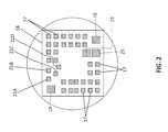
- an integrated circuit (IC) dieabuts and is proximal to the ultrasound elements, having a thickness of less than 80 ⁇ m, and further having a first face, facing the forward-facing array, and having an array of ultrasound element driving and receiving contacts, in mating arrangement to the array of ultrasound elements, so that the array of ultrasound element driving and receiving contacts collectively physically abut and electrically connect to each of the ultrasound elements; a second face, opposed to the first face, and having a set of input-output signal contacts, the set being fewer in number than the array of ultrasound element driving and receiving contacts and each being switchable into contact with any one of a set of the ultrasound element driving and receiving contacts, the second face also having a set of control contacts, wherein inputs received by the control contacts positively collectively command some aspect of operation of the IC die; and a set of amplifiers, interposed between the
- a flex circuit assemblyis proximal to the integrated circuit and includes coax cables and a contact portion, has a set of contact pads abutting and electrically connects the input-output signal contacts of the IC die to the coax cables. Finally, backing material, abutting and directly proximal to the contact portion, thereby forming an interface and wherein the backing material and the contact portion material have equal acoustic impedance, thereby preventing reflection at the interface.
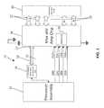
- FIG. 1is a block diagram of the ultrasound system of a medical device, according to the present invention.
- FIG. 2is a physical representation of the proximal side of the mux and amp chip shown in block form in FIG. 1 .
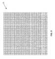
- FIG. 3is a proximal side view of the elements of the ultrasound array, shown in block form in FIG. 1 , showing one allocation of ultrasound elements into eighteen blocks 1 through H.
- FIG. 4is a side rear isometric view of the imaging head of the system of FIG. 1 .
- FIG. 5is a view of an article of flex circuit used in the system of FIG. 1 .
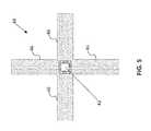
- FIG. 6is an illustration of the flip chip technique which may be used as a step in the production of the imaging head of FIG. 5 .
- FIG. 7is a side rear isometric view of the imaging head of FIG. 5 , shown including further proximal elements.
- FIG. 8is a diagram of a catheter configured for placement through an opening and into the body of a human patient or subject.
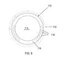
- FIG. 9is a cross-sectional view of a catheter in a Seldinger sheath.
- a processor assembly 12commands a waveform signal generating network 14 , which generates 35 MHz waveforms for 32 coax signal lines 16 , which drive and receive from a set of 32 input/output contacts 17 , on an integrated circuit die (henceforth “multiplexor chip” or “chip”) 18 .
- multiplexor chip 18is less than 12 ⁇ m in thickness. In alternative embodiments, chip 18 is less than 20, 40, 60 and 80 ⁇ m.
- Control lines 20 A- 20 Dextend from processor 12 to multiplexor 18 , attaching to contact pads 21 A- 21 D, respectively, and must command multiplexor 18 , for each phase to switch the 32 signal lines 16 to a one out of a set of 18 designated blocks 22 of drive/sense contacts, to drive one out of 18 blocks of thirty-two ultrasound elements in a 24 ⁇ 24 (576) ultrasound element array 30 .
- array 30is made of a piezoelectric material, such as a piezoelectric ceramic. It is possible that at some point another technology, such as capacitive micromachined ultrasound transducers (CMUT), may be usable in this application.
- CMUTcapacitive micromachined ultrasound transducers
- the basic function of the chip 18is to allow 32 micro-coax acoustic channels to selectively connect to any group of thirty-two ultrasound array elements and to amplify the return signals from the ultrasound elements, as they are transmitted to the coax signal lines 16 .
- the ultrasound systemresets the chip 18 and asserts the Tx/Rx line placing the MUX in transmit mode for elements 1-32.
- the ultrasound system 10then transmits an electrical analog pulse through each of the micro-coax cables 16 to contacts 17 .
- the electrical pulsesare then transferred to elements 1-32 of the piezoelectric array. After the ultrasonic pulses have left elements 1-32, the Tx/Rx line is de-asserted placing the MUX in receive mode.
- the receive modemechanical energy reflected from the tissue or blood is converted to electrical energy by the piezoelectric elements 1-32 and the power transferred back through the chip 18 where the signal is amplified (using power received on contact pad 23 ), matched to the cable and sent back through each micro-coax to the ultrasound system for conversion to digital data at the front end of the imaging system.
- the receive modelasts for approximately 8 ⁇ S. Tx/Rx is then re-asserted and the cycle repeats for elements 33-64 and so forth.
- a chip ground 25is electrically connected to a further ground at the proximal end of a linear conductor.
- the input electrical impedance of the IC chip 18 on the flex side of the chip 18is matched to that of the coaxial cable 16 (typically 50 to 100 Ohm characteristic impedance), whereas the output impedance of the IC chip 18 is matched, or optimized, to the electrical impedance of the individual piezoelectric elements of the array 30 (typically 10,000 Ohms).
- the electrical impedance matching schemeworks also in the receive cycle to enable optimal transmission of power.
- the IC chip 18performs multiple functions in the operation of the imaging system 10 : It enables the electrical connection of multiple micro-coaxial cables 16 to the individual elements of the array 30 , it matches the electrical impedance of the coaxial cables 16 to that of the piezoelectric elements, it acts as multiplexer so the entire array 30 of elements can be addressed and as an amplifier of the weak receive signals (of the order of a few microvolts) in receive mode.
- the following transmit receive sequenceis performed, where B 1 is the first block of elements, B 2 is the second block of elements and so on until B 32 is the 32 nd block of elements and TB n indicates transmission through the nth block of elements, and RB n means receiving on the nth block of elements: TB 1 ,RB 1 ,TB 1 ,RB 2 , . . . ,TB 1 ,RB n ,TB 2 ,RB 1 ,TB 2 ,RB 2 , . . . TB 2 ,RB n , . . . ,TB n RB 1 , . . . TB n (S1)
- control line 20 bis a transmit line increment.
- chip 18includes an incrementing register for transmit periods, incremented by a transmit increment line 20 b and a separate incrementing register for receive periods, incremented by a receive increment line 20 c .
- a transmit/receive selector line 20 athereby permits each to be incremented through its repeated cycles, as shown in sequence S1, listed above.
- transmit/receive selector line 20 ais used to increment the transmit and receive block registers, with for example, each rising edge counting as a transmit block increment and each falling edge counting as received block increments.
- a counteris placed in series with the transmit register so that only every 18th transition to transmit increments the transmit register and with every transition to receive incrementing the receive register, as indicated in sequence S1. This permits the transmit and receive increment lines to be eliminated.
- a single block increment linesteps through the 18 ⁇ 18 (324) transmit/receive pairs sequence S1, which must be stored in a memory 36 of chip 18 .
- Chip 18is connected to array 30 , by way of different techniques such as a flip chip bonding technique, pressure bonding through a thin layer of low viscosity adhesive (1-2 microns) or indium bonding. These are known techniques in the semiconductor/microchip industry.
- a solder ball 40FIG. 6
- these solder balls 40are pressed into array 30 , slightly crushing solder balls 40 , to form a good bond, and to create robust electrical connections between each chip contact 42 , and each element of array 30 .
- the thinness of chip 18is a great advantage, because even though solder balls 40 have some thickness, the capability of chip 18 to bend slightly, due to its thinness, greatly facilitates the formation of a robust bond between solder balls 40 and each element of array 30 .
- Adhesive filleris added among the thin solder balls 40 to increase strength as well as conduct acoustic energy into the dissipative backing.
- electrical conductivityis achieved through the surface roughness of the bonded substrates, the high points of which penetrate enough through the thin layer of adhesive to assure electrical connection.
- conductive pads on both substratesare metalized with a one to three thousand angstroms of indium which then flows through the application of heat at a low temperature (about 170 C).
- chip 18is approximately 10 ⁇ m thick thus effectively becoming an “anti-matching” layer and an integral part of the acoustic architecture as opposed to a thicker chip.
- Computer simulationsindicate that the thickness of the silicon chip 18 can be further tweaked to achieve improved pulse properties.
- the waveforms created by waveform generator 14are typically two-cycle 35 MHz pulses, having pulse width of 5.7 nsec and pulse repetition frequency for 6 mm maximum penetration of 125 kHz or pulse repetition period of 8 usec. It should be noted that other frequencies in the range of 25 to 50 MHz may be utilized depending on resolution or penetration desired.
- multiplex chip 18forms a portion of an imaging and ablation head 41 as described in detail in U.S. Pat. No. 8,702,609.
- the proximal side of multiplex chip 18is attached to a central portion 43 (which may also be referred to as the “contact portion”) of a flex circuit 44 , having four arms 46 , that are bent proximally and that each include a number of the signal coax cables 16 , and for which at least one includes one or more control lines, such as lines 20 A-D.
- Ultrasound absorbent backing material 48is proximal to central portion 42 .
- This materialis a polymer or polymer blend chosen for its ability to absorb high frequency ultrasound and in particular, ultrasound in the range of 20-50 MHz.
- the lossy backing materialhas the same acoustic impedance as the flex circuit material, including the material of contact portion 43 , to avoid reflection at the interface between the two.
- Proximal to backing material 48is a radiopaque marker 50 .
- flex circuit arms 46After extending proximally past marker 50 , flex circuit arms 46 are connected to a group of coax cables and other conductors, for signals to travel to a base station (not shown).
- ultrasound system 10is physically implemented in a vascular imaging and plaque ablation catheter system 60 .
- System 60is arranged to provide images internal to body B for medical diagnosis and/or medical treatment.
- System 60includes a control station comprising an ultrasound imaging system 62 , of which processor assembly 12 and waveform generator and receive amplifier 14 ( FIG. 1 ) form a portion, and an RF therapy system 70 , each of which are operatively coupled to catheter 80 , as well as appropriate operator input devices (e.g. keyboard and mouse or other pointing device of a standard variety) and operator display device (e.g. CRT, LCD, plasma screen, or OLED monitor).
- operator input devicese.g. keyboard and mouse or other pointing device of a standard variety
- operator display devicee.g. CRT, LCD, plasma screen, or OLED monitor.
- Catheter 80is configured for placement through opening O and into body B of a human patient or subject, as schematically represented in FIG. 8 .
- Catheter 80is preferably configured for insertion into a blood vessel or similar lumen L of the patient by any conventional vascular insertion technique.
- Catheter 80includes a guide wire lumen that extends from a proximal port 82 through the distal tip 84 of the catheter 80 , which is used to insert catheter 80 over a pre-inserted guidewire (not shown) via a conventional over the wire insertion technique.
- the guidewire exit portmay be spaced proximally from the distal tip, accordingly, to known design.
- Catheter 80may be configured with a shortened guidewire lumen so as to employ a monorail type insertion technique, or catheter 80 may be configured without any guidewire lumen and instead configured for insertion through the lumen of a pre-inserted guide catheter.
- a larger area lumen 114is available for placement of coax cables 16 , because the space for a guidewire is no longer necessary.
- RF and digital control wires 116extend inside the side wall 118 .
- a guidewireis used to facilitate the placement of the sheath 112 .
- the guidewireis removed, and the sheath 112 is then used to guide the catheter 110 .
- the number of coax cablesmay be increased, relative to an embodiment in which there is a space for a guidewire.
- 64 coaxial cablescould be fit into the catheter, indicating that a 576 element array could be driven in nine transmit/receive cycles.
- the mux and amp chip 18( FIGS. 1, 2, 4, 6, and 7 ) and ultrasound elements array 30 ( FIGS. 1, 3, 4, and 6 ) are located in distal end 84 , whereas a set of RF ablation electrodes (not shown) form distal tip 86 , which is designed to ablate arterial plaque P.
- Mini coax cables 16( FIG. 1 ) extend through a side cable 88 and then through a lumen in catheter 80 , together with control signal wires 20 A- 20 D (which in one embodiment extend through the flexible exterior wall of catheter 80 ).
- the electrode materialmay be deposited or applied directly onto the tip.
- suitable synthetic materialsinclude high temperature plastics (e.g. Torlon, available from Solvay Advanced Polymers LLC, Alpharetta, Ga.) or silicone rubber materials (e.g. RTV325, Eager Plastics, Inc. Chicago, Ill. or RTV 560 GE Plastics).
- TPX4-polymethylpentene
- TPXis a solid plastic with acoustic properties similar to human tissue and therefore transports acoustic energy to tissue efficiently with little loss.
- TPXThe acoustic impedance of human tissue is about 1.55 MRayls while that of TPX is 1.78 MRayls (implying 93% transmission). TPX also has a relatively high softening temperature (about 350 F) and melting temperature of about 460 F, which makes it suitable for the ablation application, in which elevated temperatures may occur.
Landscapes
- Health & Medical Sciences (AREA)
- Life Sciences & Earth Sciences (AREA)
- Engineering & Computer Science (AREA)
- Surgery (AREA)
- Public Health (AREA)
- Animal Behavior & Ethology (AREA)
- Veterinary Medicine (AREA)
- Nuclear Medicine, Radiotherapy & Molecular Imaging (AREA)
- Biomedical Technology (AREA)
- Heart & Thoracic Surgery (AREA)
- Medical Informatics (AREA)
- Molecular Biology (AREA)
- Physics & Mathematics (AREA)
- General Health & Medical Sciences (AREA)
- Pathology (AREA)
- Biophysics (AREA)
- Radiology & Medical Imaging (AREA)
- Cardiology (AREA)
- Plasma & Fusion (AREA)
- Otolaryngology (AREA)
- Ultra Sonic Daignosis Equipment (AREA)
- Computer Networks & Wireless Communication (AREA)
- Gynecology & Obstetrics (AREA)
Abstract
Description
TB1,RB1,TB1,RB2, . . . ,TB1,RBn,TB2,RB1,TB2,RB2, . . . TB2,RBn, . . . ,TBnRB1, . . . TBnRBn (S1)
Claims (11)
Priority Applications (3)
| Application Number | Priority Date | Filing Date | Title |
|---|---|---|---|
| US16/259,740US10492760B2 (en) | 2017-06-26 | 2019-01-28 | Image guided intravascular therapy catheter utilizing a thin chip multiplexor |
| US16/700,185US11109909B1 (en) | 2017-06-26 | 2019-12-02 | Image guided intravascular therapy catheter utilizing a thin ablation electrode |
| US17/372,795US20210338322A1 (en) | 2017-06-26 | 2021-07-12 | Method of Forming a Sound Lens |
Applications Claiming Priority (2)
| Application Number | Priority Date | Filing Date | Title |
|---|---|---|---|
| US15/633,716US10188368B2 (en) | 2017-06-26 | 2017-06-26 | Image guided intravascular therapy catheter utilizing a thin chip multiplexor |
| US16/259,740US10492760B2 (en) | 2017-06-26 | 2019-01-28 | Image guided intravascular therapy catheter utilizing a thin chip multiplexor |
Related Parent Applications (1)
| Application Number | Title | Priority Date | Filing Date |
|---|---|---|---|
| US15/633,716Continuation-In-PartUS10188368B2 (en) | 2017-06-26 | 2017-06-26 | Image guided intravascular therapy catheter utilizing a thin chip multiplexor |
Related Child Applications (1)
| Application Number | Title | Priority Date | Filing Date |
|---|---|---|---|
| US16/700,185Continuation-In-PartUS11109909B1 (en) | 2017-06-26 | 2019-12-02 | Image guided intravascular therapy catheter utilizing a thin ablation electrode |
Publications (2)
| Publication Number | Publication Date |
|---|---|
| US20190150893A1 US20190150893A1 (en) | 2019-05-23 |
| US10492760B2true US10492760B2 (en) | 2019-12-03 |
Family
ID=66534766
Family Applications (1)
| Application Number | Title | Priority Date | Filing Date |
|---|---|---|---|
| US16/259,740ActiveUS10492760B2 (en) | 2017-06-26 | 2019-01-28 | Image guided intravascular therapy catheter utilizing a thin chip multiplexor |
Country Status (1)
| Country | Link |
|---|---|
| US (1) | US10492760B2 (en) |
Cited By (1)
| Publication number | Priority date | Publication date | Assignee | Title |
|---|---|---|---|---|
| US11109909B1 (en) | 2017-06-26 | 2021-09-07 | Andreas Hadjicostis | Image guided intravascular therapy catheter utilizing a thin ablation electrode |
Citations (94)
| Publication number | Priority date | Publication date | Assignee | Title |
|---|---|---|---|---|
| US3827115A (en) | 1972-02-22 | 1974-08-06 | Univ Erasmus | Method of manufacturing a catheter |
| US3938502A (en) | 1972-02-22 | 1976-02-17 | Nicolaas Bom | Apparatus with a catheter for examining hollow organs or bodies with the ultrasonic waves |
| US4446395A (en) | 1981-12-30 | 1984-05-01 | Technicare Corporation | Short ring down, ultrasonic transducer suitable for medical applications |
| US4532924A (en) | 1980-05-13 | 1985-08-06 | American Hospital Supply Corporation | Multipolar electrosurgical device and method |
| US4643186A (en) | 1985-10-30 | 1987-02-17 | Rca Corporation | Percutaneous transluminal microwave catheter angioplasty |
| US4682596A (en) | 1984-05-22 | 1987-07-28 | Cordis Corporation | Electrosurgical catheter and method for vascular applications |
| US4794931A (en) | 1986-02-28 | 1989-01-03 | Cardiovascular Imaging Systems, Inc. | Catheter apparatus, system and method for intravascular two-dimensional ultrasonography |
| JPH02134149A (en) | 1988-09-21 | 1990-05-23 | Josef Kaliman | Catheter for removing thrombus |
| JPH02140156A (en) | 1987-10-07 | 1990-05-29 | Univ College London | surgical equipment |
| US4939826A (en) | 1988-03-04 | 1990-07-10 | Hewlett-Packard Company | Ultrasonic transducer arrays and methods for the fabrication thereof |
| US5010886A (en) | 1989-08-18 | 1991-04-30 | Intertherapy, Inc. | Medical probe assembly having combined ultrasonic imaging and laser ablation capabilities |
| US5098431A (en) | 1989-04-13 | 1992-03-24 | Everest Medical Corporation | RF ablation catheter |
| US5159931A (en) | 1988-11-25 | 1992-11-03 | Riccardo Pini | Apparatus for obtaining a three-dimensional reconstruction of anatomic structures through the acquisition of echographic images |
| US5176141A (en) | 1989-10-16 | 1993-01-05 | Du-Med B.V. | Disposable intra-luminal ultrasonic instrument |
| US5240003A (en) | 1989-10-16 | 1993-08-31 | Du-Med B.V. | Ultrasonic instrument with a micro motor having stator coils on a flexible circuit board |
| US5291893A (en) | 1992-10-09 | 1994-03-08 | Acoustic Imaging Technologies Corporation | Endo-luminal ultrasonic instrument and method for its use |
| US5327905A (en) | 1992-02-14 | 1994-07-12 | Boaz Avitall | Biplanar deflectable catheter for arrhythmogenic tissue ablation |
| US5359760A (en) | 1993-04-16 | 1994-11-01 | The Curators Of The University Of Missouri On Behalf Of The University Of Missouri-Rolla | Method of manufacture of multiple-element piezoelectric transducer |
| US5425364A (en) | 1991-02-15 | 1995-06-20 | Cardiac Pathways Corporation | Flexible strip assembly without feedthrough holes and device utilizing the same |
| WO1995019143A1 (en) | 1994-01-14 | 1995-07-20 | Paul G. Yock And Robert J. Siegel, A Joint Venture | Ultrasonic ablation of stenoses and occlusions with imaging guidance |
| US5454809A (en) | 1989-01-06 | 1995-10-03 | Angioplasty Systems, Inc. | Electrosurgical catheter and method for resolving atherosclerotic plaque by radio frequency sparking |
| US5592730A (en) | 1994-07-29 | 1997-01-14 | Hewlett-Packard Company | Method for fabricating a Z-axis conductive backing layer for acoustic transducers using etched leadframes |
| US5622177A (en) | 1993-07-08 | 1997-04-22 | Siemens Aktiengesellschaft | Ultrasound imaging system having a reduced number of lines between the base unit and the probe |
| WO1997045157A1 (en) | 1996-05-28 | 1997-12-04 | Advanced Coronary Intervention | Medical catheters for ablation and detection |
| US5771895A (en) | 1996-02-12 | 1998-06-30 | Slager; Cornelis J. | Catheter for obtaining three-dimensional reconstruction of a vascular lumen and wall |
| US5788636A (en) | 1997-02-25 | 1998-08-04 | Acuson Corporation | Method and system for forming an ultrasound image of a tissue while simultaneously ablating the tissue |
| US5840030A (en) | 1993-12-22 | 1998-11-24 | Sulzer Osypka Gmbh | Ultrasonic marked cardiac ablation catheter |
| US5840031A (en) | 1993-07-01 | 1998-11-24 | Boston Scientific Corporation | Catheters for imaging, sensing electrical potentials and ablating tissue |
| US5857974A (en) | 1997-01-08 | 1999-01-12 | Endosonics Corporation | High resolution intravascular ultrasound transducer assembly having a flexible substrate |
| WO1999012489A2 (en) | 1997-09-11 | 1999-03-18 | Vnus Medical Technologies, Inc. | Expandable vein ligator catheter and method of use |
| US5893832A (en) | 1996-06-25 | 1999-04-13 | Medison Co., Ltd. | Transducer element alignment structure in two-dimensional transducer array for forming ultra-sonic three-dimensional images |
| US5924993A (en) | 1997-10-15 | 1999-07-20 | Advanced Coronary Intervention, Inc. | Intravascular ultrasound mixed signal multiplexer/pre-amplifier asic |
| US5935108A (en) | 1997-11-14 | 1999-08-10 | Reflow, Inc. | Recanalization apparatus and devices for use therein and method |
| US6047216A (en) | 1996-04-17 | 2000-04-04 | The United States Of America Represented By The Administrator Of The National Aeronautics And Space Administration | Endothelium preserving microwave treatment for atherosclerosis |
| US6066096A (en) | 1998-05-08 | 2000-05-23 | Duke University | Imaging probes and catheters for volumetric intraluminal ultrasound imaging and related systems |
| US6099524A (en) | 1994-01-28 | 2000-08-08 | Cardiac Pacemakers, Inc. | Electrophysiological mapping and ablation catheter and method |
| US6356790B1 (en) | 1996-03-11 | 2002-03-12 | Medtronic, Inc. | Apparatus for R-F ablation |
| US6394956B1 (en) | 2000-02-29 | 2002-05-28 | Scimed Life Systems, Inc. | RF ablation and ultrasound catheter for crossing chronic total occlusions |
| US20030055308A1 (en) | 2001-08-31 | 2003-03-20 | Siemens Medical Systems, Inc. | Ultrasound imaging with acquisition of imaging data in perpendicular scan planes |
| US6560472B2 (en) | 2001-06-21 | 2003-05-06 | Microhelix, Inc. | Multi-channel structurally robust brain probe and method of making the same |
| US6582369B1 (en) | 2002-01-02 | 2003-06-24 | Computed Ultrasound Global Corporation | Method for dynamic focus control |
| US6582423B1 (en) | 1997-06-13 | 2003-06-24 | Arthrocare Corporation | Electrosurgical systems and methods for recanalization of occluded body lumens |
| US6679845B2 (en) | 2000-08-30 | 2004-01-20 | The Penn State Research Foundation | High frequency synthetic ultrasound array incorporating an actuator |
| US6709396B2 (en) | 2002-07-17 | 2004-03-23 | Vermon | Ultrasound array transducer for catheter use |
| US20040068191A1 (en) | 1991-11-08 | 2004-04-08 | Mayo Foundation For Medical Education Research | Volumetric image ultrasound transducer underfluid catheter system |
| US20040092806A1 (en) | 2001-12-11 | 2004-05-13 | Sagon Stephen W | Microelectrode catheter for mapping and ablation |
| US20040147920A1 (en) | 2002-10-21 | 2004-07-29 | Yaron Keidar | Prediction and assessment of ablation of cardiac tissue |
| US6783497B2 (en) | 2002-05-23 | 2004-08-31 | Volumetrics Medical Imaging, Inc. | Two-dimensional ultrasonic array with asymmetric apertures |
| US20040254570A1 (en) | 2003-06-13 | 2004-12-16 | Andreas Hadjicostis | Endoscopic medical treatment involving acoustic ablation |
| US20040254471A1 (en) | 2003-06-13 | 2004-12-16 | Andreas Hadjicostis | Miniature ultrasonic phased array for intracardiac and intracavity applications |
| US6852109B2 (en) | 2002-06-11 | 2005-02-08 | Intraluminal Therapeutics, Inc. | Radio frequency guide wire assembly with optical coherence reflectometry guidance |
| US20050033182A1 (en) | 2003-07-01 | 2005-02-10 | Marino Cerofolini | Electronic array probe for ultrasonic imaging |
| US6858006B2 (en) | 2000-09-08 | 2005-02-22 | Wireless Medical, Inc. | Cardiopulmonary monitoring |
| US20050107783A1 (en) | 1999-08-05 | 2005-05-19 | Broncus Technologies, Inc. | Devices for applying energy to tissue |
| US20050159739A1 (en) | 2004-01-16 | 2005-07-21 | Saurav Paul | Brush electrode and method for ablation |
| US6925693B2 (en) | 1998-12-28 | 2005-08-09 | Ngk Insulators, Ltd. | Method of fabricating a piezoelectric/electrostrictive device |
| US20050228290A1 (en) | 2004-04-07 | 2005-10-13 | Ep Medsystems, Inc. | Steerable ultrasound catheter |
| US6962567B2 (en) | 1993-02-01 | 2005-11-08 | Volcano Therapeutics, Inc. | Ultrasound transducer assembly |
| US20050251127A1 (en) | 2003-10-15 | 2005-11-10 | Jared Brosch | Miniature ultrasonic transducer with focusing lens for intracardiac and intracavity applications |
| US6972018B2 (en) | 2002-06-28 | 2005-12-06 | Gynecare A Division Of Ethicon, Inc. | Apparatus and method for transcervical sterilization by application of ultrasound |
| US6994674B2 (en) | 2002-06-27 | 2006-02-07 | Siemens Medical Solutions Usa, Inc. | Multi-dimensional transducer arrays and method of manufacture |
| US20060030844A1 (en) | 2004-08-04 | 2006-02-09 | Knight Bradley P | Transparent electrode for the radiofrequency ablation of tissue |
| US7004940B2 (en) | 2002-10-10 | 2006-02-28 | Ethicon, Inc. | Devices for performing thermal ablation having movable ultrasound transducers |
| US7022088B2 (en) | 1999-08-05 | 2006-04-04 | Broncus Technologies, Inc. | Devices for applying energy to tissue |
| US7045108B2 (en) | 2002-09-16 | 2006-05-16 | Tsinghua University | Method for fabricating carbon nanotube yarn |
| US7053530B2 (en) | 2002-11-22 | 2006-05-30 | General Electric Company | Method for making electrical connection to ultrasonic transducer through acoustic backing material |
| US7060033B2 (en) | 1997-09-29 | 2006-06-13 | Boston Scientific Corporation | Ultrasound imaging guidewire with static central core and tip |
| US7066895B2 (en) | 2003-06-30 | 2006-06-27 | Ethicon, Inc. | Ultrasonic radial focused transducer for pulmonary vein ablation |
| US7074218B2 (en) | 2003-06-30 | 2006-07-11 | Ethicon, Inc. | Multi-modality ablation device |
| US7112196B2 (en) | 2003-06-13 | 2006-09-26 | Piezo Technologies, Inc. | Multi-element array for acoustic ablation |
| US7115092B2 (en) | 2002-09-18 | 2006-10-03 | The Board Of Trustees Of The Leland Stanford Junior University | Tubular compliant mechanisms for ultrasonic imaging systems and intravascular interventional devices |
| KR20060112244A (en) | 2005-04-26 | 2006-10-31 | 바이오센스 웹스터 인코포레이티드 | Display of catheter tip with beam direction for ultrasound system |
| EP1717601A2 (en) | 2005-04-26 | 2006-11-02 | Biosense Webster, Inc. | Display of catheter tip with beam direction for ultrasound system |
| US7156938B2 (en) | 2003-11-11 | 2007-01-02 | General Electric Company | Method for making multi-layer ceramic acoustic transducer |
| US7195179B2 (en) | 2003-06-01 | 2007-03-27 | Piezo Technologies | Piezoelectric mist generation device |
| US7226417B1 (en) | 1995-12-26 | 2007-06-05 | Volcano Corporation | High resolution intravascular ultrasound transducer assembly having a flexible substrate |
| US20070167804A1 (en) | 2002-09-18 | 2007-07-19 | Byong-Ho Park | Tubular compliant mechanisms for ultrasonic imaging systems and intravascular interventional devices |
| US20070189761A1 (en) | 2003-12-04 | 2007-08-16 | Wojtek Sudol | Implementing ic mounted sensor with high attenutation backing |
| US20070246821A1 (en) | 2006-04-20 | 2007-10-25 | Lu Szu W | Utra-thin substrate package technology |
| US20080200815A1 (en) | 2004-08-13 | 2008-08-21 | Stichting Voor De Technische Wetenschappen | Intravascular Ultrasound Techniques |
| US7519410B2 (en) | 2002-12-12 | 2009-04-14 | Boston Scientific Scimed, Inc. | La placian electrode |
| US7596415B2 (en) | 2002-12-06 | 2009-09-29 | Medtronic, Inc. | Medical devices incorporating carbon nanotube material and methods of fabricating same |
| EP2136603A2 (en) | 2008-06-18 | 2009-12-23 | Tsing Hua University | Heater and method for making the same |
| US7844347B2 (en) | 2002-12-06 | 2010-11-30 | Medtronic, Inc. | Medical devices incorporating carbon nanotube material and methods of fabricating same |
| US8414492B2 (en) | 2007-07-27 | 2013-04-09 | Meridian Cardiovascular Systems, Inc. | Image guided intracardiac catheters |
| US20130267853A1 (en) | 2010-12-03 | 2013-10-10 | Research Triangle Institute | Ultrasound device, and associated cable assembly |
| US8702609B2 (en) | 2007-07-27 | 2014-04-22 | Meridian Cardiovascular Systems, Inc. | Image-guided intravascular therapy catheters |
| US8974446B2 (en) | 2001-10-11 | 2015-03-10 | St. Jude Medical, Inc. | Ultrasound ablation apparatus with discrete staggered ablation zones |
| US20150099976A1 (en) | 2008-10-07 | 2015-04-09 | Mc10 Inc. | Systems, methods, and devices using stretchable or flexible electronics for medical applications |
| US20160008067A1 (en) | 2007-07-27 | 2016-01-14 | Andreas Hadjicostis | Device for Ablating Arterial Plaque |
| US20160113633A1 (en) | 2014-02-27 | 2016-04-28 | Andreas Hadjicostis | Device for ablating arterial plaque |
| CN106037803A (en) | 2016-06-27 | 2016-10-26 | 中国科学院苏州生物医学工程技术研究所 | Ultrasonic transducer array, ultrasonic intervention treatment system and ultrasonic ablation catheter |
| US20160374710A1 (en) | 2014-03-12 | 2016-12-29 | Yegor D. Sinelnikov | Carotid body ablation with a transvenous ultrasound imaging and ablation catheter |
| US20180368805A1 (en) | 2017-06-26 | 2018-12-27 | Andreas Hadjicostis | Image Guided Intravascular Therapy Catheter Utilizing a Thin Chip Multiplexor |
- 2019
- 2019-01-28USUS16/259,740patent/US10492760B2/enactiveActive
Patent Citations (104)
| Publication number | Priority date | Publication date | Assignee | Title |
|---|---|---|---|---|
| US3827115A (en) | 1972-02-22 | 1974-08-06 | Univ Erasmus | Method of manufacturing a catheter |
| US3938502A (en) | 1972-02-22 | 1976-02-17 | Nicolaas Bom | Apparatus with a catheter for examining hollow organs or bodies with the ultrasonic waves |
| US4532924A (en) | 1980-05-13 | 1985-08-06 | American Hospital Supply Corporation | Multipolar electrosurgical device and method |
| US4446395A (en) | 1981-12-30 | 1984-05-01 | Technicare Corporation | Short ring down, ultrasonic transducer suitable for medical applications |
| US4682596A (en) | 1984-05-22 | 1987-07-28 | Cordis Corporation | Electrosurgical catheter and method for vascular applications |
| US4643186A (en) | 1985-10-30 | 1987-02-17 | Rca Corporation | Percutaneous transluminal microwave catheter angioplasty |
| US4794931A (en) | 1986-02-28 | 1989-01-03 | Cardiovascular Imaging Systems, Inc. | Catheter apparatus, system and method for intravascular two-dimensional ultrasonography |
| JPH02140156A (en) | 1987-10-07 | 1990-05-29 | Univ College London | surgical equipment |
| US4939826A (en) | 1988-03-04 | 1990-07-10 | Hewlett-Packard Company | Ultrasonic transducer arrays and methods for the fabrication thereof |
| JPH02134149A (en) | 1988-09-21 | 1990-05-23 | Josef Kaliman | Catheter for removing thrombus |
| US5159931A (en) | 1988-11-25 | 1992-11-03 | Riccardo Pini | Apparatus for obtaining a three-dimensional reconstruction of anatomic structures through the acquisition of echographic images |
| US5454809A (en) | 1989-01-06 | 1995-10-03 | Angioplasty Systems, Inc. | Electrosurgical catheter and method for resolving atherosclerotic plaque by radio frequency sparking |
| US5749914A (en) | 1989-01-06 | 1998-05-12 | Advanced Coronary Intervention | Catheter for obstructed stent |
| US5626576A (en) | 1989-01-06 | 1997-05-06 | Advanced Coronary Intervention, Inc. | Electrosurgical catheter for resolving atherosclerotic plaque by radio frequency sparking |
| US5098431A (en) | 1989-04-13 | 1992-03-24 | Everest Medical Corporation | RF ablation catheter |
| US5010886A (en) | 1989-08-18 | 1991-04-30 | Intertherapy, Inc. | Medical probe assembly having combined ultrasonic imaging and laser ablation capabilities |
| US5176141A (en) | 1989-10-16 | 1993-01-05 | Du-Med B.V. | Disposable intra-luminal ultrasonic instrument |
| US5240003A (en) | 1989-10-16 | 1993-08-31 | Du-Med B.V. | Ultrasonic instrument with a micro motor having stator coils on a flexible circuit board |
| US5425364A (en) | 1991-02-15 | 1995-06-20 | Cardiac Pathways Corporation | Flexible strip assembly without feedthrough holes and device utilizing the same |
| US7156812B2 (en) | 1991-11-08 | 2007-01-02 | Mayo Foundation For Medical Education & Research | Volumetric image ultrasound transducer underfluid catheter system |
| US20040068191A1 (en) | 1991-11-08 | 2004-04-08 | Mayo Foundation For Medical Education Research | Volumetric image ultrasound transducer underfluid catheter system |
| US5327905A (en) | 1992-02-14 | 1994-07-12 | Boaz Avitall | Biplanar deflectable catheter for arrhythmogenic tissue ablation |
| US5291893A (en) | 1992-10-09 | 1994-03-08 | Acoustic Imaging Technologies Corporation | Endo-luminal ultrasonic instrument and method for its use |
| US6962567B2 (en) | 1993-02-01 | 2005-11-08 | Volcano Therapeutics, Inc. | Ultrasound transducer assembly |
| US5359760A (en) | 1993-04-16 | 1994-11-01 | The Curators Of The University Of Missouri On Behalf Of The University Of Missouri-Rolla | Method of manufacture of multiple-element piezoelectric transducer |
| US5840031A (en) | 1993-07-01 | 1998-11-24 | Boston Scientific Corporation | Catheters for imaging, sensing electrical potentials and ablating tissue |
| US5622177A (en) | 1993-07-08 | 1997-04-22 | Siemens Aktiengesellschaft | Ultrasound imaging system having a reduced number of lines between the base unit and the probe |
| US5840030A (en) | 1993-12-22 | 1998-11-24 | Sulzer Osypka Gmbh | Ultrasonic marked cardiac ablation catheter |
| WO1995019143A1 (en) | 1994-01-14 | 1995-07-20 | Paul G. Yock And Robert J. Siegel, A Joint Venture | Ultrasonic ablation of stenoses and occlusions with imaging guidance |
| US6099524A (en) | 1994-01-28 | 2000-08-08 | Cardiac Pacemakers, Inc. | Electrophysiological mapping and ablation catheter and method |
| US5592730A (en) | 1994-07-29 | 1997-01-14 | Hewlett-Packard Company | Method for fabricating a Z-axis conductive backing layer for acoustic transducers using etched leadframes |
| US7226417B1 (en) | 1995-12-26 | 2007-06-05 | Volcano Corporation | High resolution intravascular ultrasound transducer assembly having a flexible substrate |
| US5771895A (en) | 1996-02-12 | 1998-06-30 | Slager; Cornelis J. | Catheter for obtaining three-dimensional reconstruction of a vascular lumen and wall |
| US6356790B1 (en) | 1996-03-11 | 2002-03-12 | Medtronic, Inc. | Apparatus for R-F ablation |
| US6047216A (en) | 1996-04-17 | 2000-04-04 | The United States Of America Represented By The Administrator Of The National Aeronautics And Space Administration | Endothelium preserving microwave treatment for atherosclerosis |
| WO1997045157A1 (en) | 1996-05-28 | 1997-12-04 | Advanced Coronary Intervention | Medical catheters for ablation and detection |
| US5893832A (en) | 1996-06-25 | 1999-04-13 | Medison Co., Ltd. | Transducer element alignment structure in two-dimensional transducer array for forming ultra-sonic three-dimensional images |
| US5857974A (en) | 1997-01-08 | 1999-01-12 | Endosonics Corporation | High resolution intravascular ultrasound transducer assembly having a flexible substrate |
| US6899682B2 (en) | 1997-01-08 | 2005-05-31 | Volcano Therapeutics, Inc. | Intravascular ultrasound transducer assembly having a flexible substrate and method for manufacturing such assembly |
| US5788636A (en) | 1997-02-25 | 1998-08-04 | Acuson Corporation | Method and system for forming an ultrasound image of a tissue while simultaneously ablating the tissue |
| US6582423B1 (en) | 1997-06-13 | 2003-06-24 | Arthrocare Corporation | Electrosurgical systems and methods for recanalization of occluded body lumens |
| WO1999012489A2 (en) | 1997-09-11 | 1999-03-18 | Vnus Medical Technologies, Inc. | Expandable vein ligator catheter and method of use |
| US7060033B2 (en) | 1997-09-29 | 2006-06-13 | Boston Scientific Corporation | Ultrasound imaging guidewire with static central core and tip |
| US5924993A (en) | 1997-10-15 | 1999-07-20 | Advanced Coronary Intervention, Inc. | Intravascular ultrasound mixed signal multiplexer/pre-amplifier asic |
| US5935108A (en) | 1997-11-14 | 1999-08-10 | Reflow, Inc. | Recanalization apparatus and devices for use therein and method |
| US6066096A (en) | 1998-05-08 | 2000-05-23 | Duke University | Imaging probes and catheters for volumetric intraluminal ultrasound imaging and related systems |
| US6572551B1 (en) | 1998-05-08 | 2003-06-03 | Duke University | Imaging catheters for volumetric intraluminal ultrasound imaging |
| US6925693B2 (en) | 1998-12-28 | 2005-08-09 | Ngk Insulators, Ltd. | Method of fabricating a piezoelectric/electrostrictive device |
| US7022088B2 (en) | 1999-08-05 | 2006-04-04 | Broncus Technologies, Inc. | Devices for applying energy to tissue |
| US20050107783A1 (en) | 1999-08-05 | 2005-05-19 | Broncus Technologies, Inc. | Devices for applying energy to tissue |
| US6394956B1 (en) | 2000-02-29 | 2002-05-28 | Scimed Life Systems, Inc. | RF ablation and ultrasound catheter for crossing chronic total occlusions |
| US6679845B2 (en) | 2000-08-30 | 2004-01-20 | The Penn State Research Foundation | High frequency synthetic ultrasound array incorporating an actuator |
| US6858006B2 (en) | 2000-09-08 | 2005-02-22 | Wireless Medical, Inc. | Cardiopulmonary monitoring |
| US6560472B2 (en) | 2001-06-21 | 2003-05-06 | Microhelix, Inc. | Multi-channel structurally robust brain probe and method of making the same |
| US6892438B1 (en) | 2001-06-21 | 2005-05-17 | Advanced Neuromodulation Systems, Inc. | Method of making a bio-probe |
| US20030055308A1 (en) | 2001-08-31 | 2003-03-20 | Siemens Medical Systems, Inc. | Ultrasound imaging with acquisition of imaging data in perpendicular scan planes |
| US8974446B2 (en) | 2001-10-11 | 2015-03-10 | St. Jude Medical, Inc. | Ultrasound ablation apparatus with discrete staggered ablation zones |
| US20040092806A1 (en) | 2001-12-11 | 2004-05-13 | Sagon Stephen W | Microelectrode catheter for mapping and ablation |
| US6582369B1 (en) | 2002-01-02 | 2003-06-24 | Computed Ultrasound Global Corporation | Method for dynamic focus control |
| US6783497B2 (en) | 2002-05-23 | 2004-08-31 | Volumetrics Medical Imaging, Inc. | Two-dimensional ultrasonic array with asymmetric apertures |
| US6852109B2 (en) | 2002-06-11 | 2005-02-08 | Intraluminal Therapeutics, Inc. | Radio frequency guide wire assembly with optical coherence reflectometry guidance |
| US6994674B2 (en) | 2002-06-27 | 2006-02-07 | Siemens Medical Solutions Usa, Inc. | Multi-dimensional transducer arrays and method of manufacture |
| US6972018B2 (en) | 2002-06-28 | 2005-12-06 | Gynecare A Division Of Ethicon, Inc. | Apparatus and method for transcervical sterilization by application of ultrasound |
| US6709396B2 (en) | 2002-07-17 | 2004-03-23 | Vermon | Ultrasound array transducer for catheter use |
| US7045108B2 (en) | 2002-09-16 | 2006-05-16 | Tsinghua University | Method for fabricating carbon nanotube yarn |
| US20070167804A1 (en) | 2002-09-18 | 2007-07-19 | Byong-Ho Park | Tubular compliant mechanisms for ultrasonic imaging systems and intravascular interventional devices |
| US7115092B2 (en) | 2002-09-18 | 2006-10-03 | The Board Of Trustees Of The Leland Stanford Junior University | Tubular compliant mechanisms for ultrasonic imaging systems and intravascular interventional devices |
| US7004940B2 (en) | 2002-10-10 | 2006-02-28 | Ethicon, Inc. | Devices for performing thermal ablation having movable ultrasound transducers |
| US20040147920A1 (en) | 2002-10-21 | 2004-07-29 | Yaron Keidar | Prediction and assessment of ablation of cardiac tissue |
| US7053530B2 (en) | 2002-11-22 | 2006-05-30 | General Electric Company | Method for making electrical connection to ultrasonic transducer through acoustic backing material |
| US7596415B2 (en) | 2002-12-06 | 2009-09-29 | Medtronic, Inc. | Medical devices incorporating carbon nanotube material and methods of fabricating same |
| US7844347B2 (en) | 2002-12-06 | 2010-11-30 | Medtronic, Inc. | Medical devices incorporating carbon nanotube material and methods of fabricating same |
| US7519410B2 (en) | 2002-12-12 | 2009-04-14 | Boston Scientific Scimed, Inc. | La placian electrode |
| US7195179B2 (en) | 2003-06-01 | 2007-03-27 | Piezo Technologies | Piezoelectric mist generation device |
| US20040254570A1 (en) | 2003-06-13 | 2004-12-16 | Andreas Hadjicostis | Endoscopic medical treatment involving acoustic ablation |
| US20040254471A1 (en) | 2003-06-13 | 2004-12-16 | Andreas Hadjicostis | Miniature ultrasonic phased array for intracardiac and intracavity applications |
| US7112196B2 (en) | 2003-06-13 | 2006-09-26 | Piezo Technologies, Inc. | Multi-element array for acoustic ablation |
| US7066895B2 (en) | 2003-06-30 | 2006-06-27 | Ethicon, Inc. | Ultrasonic radial focused transducer for pulmonary vein ablation |
| US7074218B2 (en) | 2003-06-30 | 2006-07-11 | Ethicon, Inc. | Multi-modality ablation device |
| US20050033182A1 (en) | 2003-07-01 | 2005-02-10 | Marino Cerofolini | Electronic array probe for ultrasonic imaging |
| US20050251127A1 (en) | 2003-10-15 | 2005-11-10 | Jared Brosch | Miniature ultrasonic transducer with focusing lens for intracardiac and intracavity applications |
| US7156938B2 (en) | 2003-11-11 | 2007-01-02 | General Electric Company | Method for making multi-layer ceramic acoustic transducer |
| US20070189761A1 (en) | 2003-12-04 | 2007-08-16 | Wojtek Sudol | Implementing ic mounted sensor with high attenutation backing |
| US20050159739A1 (en) | 2004-01-16 | 2005-07-21 | Saurav Paul | Brush electrode and method for ablation |
| US20050228290A1 (en) | 2004-04-07 | 2005-10-13 | Ep Medsystems, Inc. | Steerable ultrasound catheter |
| US20060030844A1 (en) | 2004-08-04 | 2006-02-09 | Knight Bradley P | Transparent electrode for the radiofrequency ablation of tissue |
| US20080200815A1 (en) | 2004-08-13 | 2008-08-21 | Stichting Voor De Technische Wetenschappen | Intravascular Ultrasound Techniques |
| KR20060112244A (en) | 2005-04-26 | 2006-10-31 | 바이오센스 웹스터 인코포레이티드 | Display of catheter tip with beam direction for ultrasound system |
| EP1717601A2 (en) | 2005-04-26 | 2006-11-02 | Biosense Webster, Inc. | Display of catheter tip with beam direction for ultrasound system |
| US20070246821A1 (en) | 2006-04-20 | 2007-10-25 | Lu Szu W | Utra-thin substrate package technology |
| US8425421B2 (en) | 2007-07-27 | 2013-04-23 | Meredian Cardiovascular Systems, Inc. | Intracardiac catheters with image field electrodes |
| US9138290B2 (en) | 2007-07-27 | 2015-09-22 | Meridian Cardiovascular Systems, Inc. | Method of ablating arterial plaque |
| US20160008067A1 (en) | 2007-07-27 | 2016-01-14 | Andreas Hadjicostis | Device for Ablating Arterial Plaque |
| US8702609B2 (en) | 2007-07-27 | 2014-04-22 | Meridian Cardiovascular Systems, Inc. | Image-guided intravascular therapy catheters |
| US20140180101A1 (en) | 2007-07-27 | 2014-06-26 | Andreas Hadjicostis | Method of Ablating Arterial Plaque |
| US8414492B2 (en) | 2007-07-27 | 2013-04-09 | Meridian Cardiovascular Systems, Inc. | Image guided intracardiac catheters |
| EP2136603A2 (en) | 2008-06-18 | 2009-12-23 | Tsing Hua University | Heater and method for making the same |
| US20150099976A1 (en) | 2008-10-07 | 2015-04-09 | Mc10 Inc. | Systems, methods, and devices using stretchable or flexible electronics for medical applications |
| US20130267853A1 (en) | 2010-12-03 | 2013-10-10 | Research Triangle Institute | Ultrasound device, and associated cable assembly |
| US20160113633A1 (en) | 2014-02-27 | 2016-04-28 | Andreas Hadjicostis | Device for ablating arterial plaque |
| US20160374710A1 (en) | 2014-03-12 | 2016-12-29 | Yegor D. Sinelnikov | Carotid body ablation with a transvenous ultrasound imaging and ablation catheter |
| CN106037803A (en) | 2016-06-27 | 2016-10-26 | 中国科学院苏州生物医学工程技术研究所 | Ultrasonic transducer array, ultrasonic intervention treatment system and ultrasonic ablation catheter |
| US20180368805A1 (en) | 2017-06-26 | 2018-12-27 | Andreas Hadjicostis | Image Guided Intravascular Therapy Catheter Utilizing a Thin Chip Multiplexor |
| US10188368B2 (en)* | 2017-06-26 | 2019-01-29 | Andreas Hadjicostis | Image guided intravascular therapy catheter utilizing a thin chip multiplexor |
Cited By (1)
| Publication number | Priority date | Publication date | Assignee | Title |
|---|---|---|---|---|
| US11109909B1 (en) | 2017-06-26 | 2021-09-07 | Andreas Hadjicostis | Image guided intravascular therapy catheter utilizing a thin ablation electrode |
Also Published As
| Publication number | Publication date |
|---|---|
| US20190150893A1 (en) | 2019-05-23 |
Similar Documents
| Publication | Publication Date | Title |
|---|---|---|
| US12144678B2 (en) | Catheter with integrated controller for imaging and pressure sensing | |
| JP7351972B2 (en) | Wireless intraluminal imaging devices and systems | |
| US9138290B2 (en) | Method of ablating arterial plaque | |
| US10188368B2 (en) | Image guided intravascular therapy catheter utilizing a thin chip multiplexor | |
| US12324701B2 (en) | Intra-cardiac echocardiography interposer | |
| US11911217B2 (en) | Intraluminal imaging devices with a reduced number of signal channels | |
| US20160113633A1 (en) | Device for ablating arterial plaque | |
| US20160008067A1 (en) | Device for Ablating Arterial Plaque | |
| WO2021030470A2 (en) | Multiple sensor catheter assembly | |
| US10492760B2 (en) | Image guided intravascular therapy catheter utilizing a thin chip multiplexor | |
| US20210338322A1 (en) | Method of Forming a Sound Lens | |
| Light et al. | New ring array transducers for real-time 3D intravascular ultrasound |
Legal Events
| Date | Code | Title | Description |
|---|---|---|---|
| FEPP | Fee payment procedure | Free format text:ENTITY STATUS SET TO UNDISCOUNTED (ORIGINAL EVENT CODE: BIG.); ENTITY STATUS OF PATENT OWNER: SMALL ENTITY | |
| FEPP | Fee payment procedure | Free format text:ENTITY STATUS SET TO SMALL (ORIGINAL EVENT CODE: SMAL); ENTITY STATUS OF PATENT OWNER: SMALL ENTITY | |
| STPP | Information on status: patent application and granting procedure in general | Free format text:NON FINAL ACTION MAILED | |
| STPP | Information on status: patent application and granting procedure in general | Free format text:NOTICE OF ALLOWANCE MAILED -- APPLICATION RECEIVED IN OFFICE OF PUBLICATIONS | |
| STPP | Information on status: patent application and granting procedure in general | Free format text:NOTICE OF ALLOWANCE MAILED -- APPLICATION RECEIVED IN OFFICE OF PUBLICATIONS | |
| STPP | Information on status: patent application and granting procedure in general | Free format text:PUBLICATIONS -- ISSUE FEE PAYMENT VERIFIED | |
| STCF | Information on status: patent grant | Free format text:PATENTED CASE | |
| AS | Assignment | Owner name:MERIDIAN CARDIOVASCULAR SYSTEMS INC., TEXAS Free format text:ASSIGNMENT OF ASSIGNORS INTEREST;ASSIGNOR:HADJICOSTIS, ANDREAS;REEL/FRAME:051331/0189 Effective date:20191219 | |
| FEPP | Fee payment procedure | Free format text:MAINTENANCE FEE REMINDER MAILED (ORIGINAL EVENT CODE: REM.); ENTITY STATUS OF PATENT OWNER: SMALL ENTITY | |
| FEPP | Fee payment procedure | Free format text:SURCHARGE FOR LATE PAYMENT, SMALL ENTITY (ORIGINAL EVENT CODE: M2554); ENTITY STATUS OF PATENT OWNER: SMALL ENTITY | |
| MAFP | Maintenance fee payment | Free format text:PAYMENT OF MAINTENANCE FEE, 4TH YR, SMALL ENTITY (ORIGINAL EVENT CODE: M2551); ENTITY STATUS OF PATENT OWNER: SMALL ENTITY Year of fee payment:4 |