US10492605B2 - Mounting bracket for equipment rack - Google Patents
Mounting bracket for equipment rackDownload PDFInfo
- Publication number
- US10492605B2 US10492605B2US15/418,137US201715418137AUS10492605B2US 10492605 B2US10492605 B2US 10492605B2US 201715418137 AUS201715418137 AUS 201715418137AUS 10492605 B2US10492605 B2US 10492605B2
- Authority
- US
- United States
- Prior art keywords
- bracket
- snap
- frame assembly
- fit
- connection
- Prior art date
- Legal status (The legal status is an assumption and is not a legal conclusion. Google has not performed a legal analysis and makes no representation as to the accuracy of the status listed.)
- Active, expires
Links
Images


Classifications
- H—ELECTRICITY
- H05—ELECTRIC TECHNIQUES NOT OTHERWISE PROVIDED FOR
- H05K—PRINTED CIRCUITS; CASINGS OR CONSTRUCTIONAL DETAILS OF ELECTRIC APPARATUS; MANUFACTURE OF ASSEMBLAGES OF ELECTRICAL COMPONENTS
- H05K7/00—Constructional details common to different types of electric apparatus
- H05K7/14—Mounting supporting structure in casing or on frame or rack
- H05K7/1401—Mounting supporting structure in casing or on frame or rack comprising clamping or extracting means
- A—HUMAN NECESSITIES
- A47—FURNITURE; DOMESTIC ARTICLES OR APPLIANCES; COFFEE MILLS; SPICE MILLS; SUCTION CLEANERS IN GENERAL
- A47B—TABLES; DESKS; OFFICE FURNITURE; CABINETS; DRAWERS; GENERAL DETAILS OF FURNITURE
- A47B57/00—Cabinets, racks or shelf units, characterised by features for adjusting shelves or partitions
- A47B57/30—Cabinets, racks or shelf units, characterised by features for adjusting shelves or partitions with means for adjusting the height of detachable shelf supports
- A47B57/54—Cabinets, racks or shelf units, characterised by features for adjusting shelves or partitions with means for adjusting the height of detachable shelf supports consisting of clamping means, e.g. with sliding bolts or sliding wedges
- A—HUMAN NECESSITIES
- A47—FURNITURE; DOMESTIC ARTICLES OR APPLIANCES; COFFEE MILLS; SPICE MILLS; SUCTION CLEANERS IN GENERAL
- A47B—TABLES; DESKS; OFFICE FURNITURE; CABINETS; DRAWERS; GENERAL DETAILS OF FURNITURE
- A47B47/00—Cabinets, racks or shelf units, characterised by features related to dismountability or building-up from elements
- A47B47/0083—Cabinets, racks or shelf units, characterised by features related to dismountability or building-up from elements with four vertical uprights
- A—HUMAN NECESSITIES
- A47—FURNITURE; DOMESTIC ARTICLES OR APPLIANCES; COFFEE MILLS; SPICE MILLS; SUCTION CLEANERS IN GENERAL
- A47B—TABLES; DESKS; OFFICE FURNITURE; CABINETS; DRAWERS; GENERAL DETAILS OF FURNITURE
- A47B57/00—Cabinets, racks or shelf units, characterised by features for adjusting shelves or partitions
- A47B57/30—Cabinets, racks or shelf units, characterised by features for adjusting shelves or partitions with means for adjusting the height of detachable shelf supports
- A47B57/32—Cabinets, racks or shelf units, characterised by features for adjusting shelves or partitions with means for adjusting the height of detachable shelf supports consisting of grooved or notched ledges, uprights or side walls
- A47B57/34—Cabinets, racks or shelf units, characterised by features for adjusting shelves or partitions with means for adjusting the height of detachable shelf supports consisting of grooved or notched ledges, uprights or side walls the grooved or notched parts being the side walls or uprights themselves
- A—HUMAN NECESSITIES
- A47—FURNITURE; DOMESTIC ARTICLES OR APPLIANCES; COFFEE MILLS; SPICE MILLS; SUCTION CLEANERS IN GENERAL
- A47B—TABLES; DESKS; OFFICE FURNITURE; CABINETS; DRAWERS; GENERAL DETAILS OF FURNITURE
- A47B57/00—Cabinets, racks or shelf units, characterised by features for adjusting shelves or partitions
- A47B57/30—Cabinets, racks or shelf units, characterised by features for adjusting shelves or partitions with means for adjusting the height of detachable shelf supports
- A47B57/54—Cabinets, racks or shelf units, characterised by features for adjusting shelves or partitions with means for adjusting the height of detachable shelf supports consisting of clamping means, e.g. with sliding bolts or sliding wedges
- A47B57/545—Cabinets, racks or shelf units, characterised by features for adjusting shelves or partitions with means for adjusting the height of detachable shelf supports consisting of clamping means, e.g. with sliding bolts or sliding wedges clamped in discrete positions, e.g. on tubes with grooves or holes
- A—HUMAN NECESSITIES
- A47—FURNITURE; DOMESTIC ARTICLES OR APPLIANCES; COFFEE MILLS; SPICE MILLS; SUCTION CLEANERS IN GENERAL
- A47B—TABLES; DESKS; OFFICE FURNITURE; CABINETS; DRAWERS; GENERAL DETAILS OF FURNITURE
- A47B88/00—Drawers for tables, cabinets or like furniture; Guides for drawers
- A47B88/40—Sliding drawers; Slides or guides therefor
- A47B88/423—Fastening devices for slides or guides
- A47B88/43—Fastening devices for slides or guides at cabinet side
- A—HUMAN NECESSITIES
- A47—FURNITURE; DOMESTIC ARTICLES OR APPLIANCES; COFFEE MILLS; SPICE MILLS; SUCTION CLEANERS IN GENERAL
- A47B—TABLES; DESKS; OFFICE FURNITURE; CABINETS; DRAWERS; GENERAL DETAILS OF FURNITURE
- A47B96/00—Details of cabinets, racks or shelf units not covered by a single one of groups A47B43/00 - A47B95/00; General details of furniture
- A47B96/06—Brackets or similar supporting means for cabinets, racks or shelves
- A—HUMAN NECESSITIES
- A47—FURNITURE; DOMESTIC ARTICLES OR APPLIANCES; COFFEE MILLS; SPICE MILLS; SUCTION CLEANERS IN GENERAL
- A47B—TABLES; DESKS; OFFICE FURNITURE; CABINETS; DRAWERS; GENERAL DETAILS OF FURNITURE
- A47B96/00—Details of cabinets, racks or shelf units not covered by a single one of groups A47B43/00 - A47B95/00; General details of furniture
- A47B96/14—Bars, uprights, struts, or like supports, for cabinets, brackets, or the like
- A47B96/1441—Horizontal struts
- A—HUMAN NECESSITIES
- A47—FURNITURE; DOMESTIC ARTICLES OR APPLIANCES; COFFEE MILLS; SPICE MILLS; SUCTION CLEANERS IN GENERAL
- A47B—TABLES; DESKS; OFFICE FURNITURE; CABINETS; DRAWERS; GENERAL DETAILS OF FURNITURE
- A47B96/00—Details of cabinets, racks or shelf units not covered by a single one of groups A47B43/00 - A47B95/00; General details of furniture
- A47B96/20—Furniture panels or like furniture elements
- H—ELECTRICITY
- H05—ELECTRIC TECHNIQUES NOT OTHERWISE PROVIDED FOR
- H05K—PRINTED CIRCUITS; CASINGS OR CONSTRUCTIONAL DETAILS OF ELECTRIC APPARATUS; MANUFACTURE OF ASSEMBLAGES OF ELECTRICAL COMPONENTS
- H05K7/00—Constructional details common to different types of electric apparatus
- H05K7/14—Mounting supporting structure in casing or on frame or rack
- H05K7/1485—Servers; Data center rooms, e.g. 19-inch computer racks
- H05K7/1488—Cabinets therefor, e.g. chassis or racks or mechanical interfaces between blades and support structures
- H05K7/1489—Cabinets therefor, e.g. chassis or racks or mechanical interfaces between blades and support structures characterized by the mounting of blades therein, e.g. brackets, rails, trays
- H—ELECTRICITY
- H05—ELECTRIC TECHNIQUES NOT OTHERWISE PROVIDED FOR
- H05K—PRINTED CIRCUITS; CASINGS OR CONSTRUCTIONAL DETAILS OF ELECTRIC APPARATUS; MANUFACTURE OF ASSEMBLAGES OF ELECTRICAL COMPONENTS
- H05K7/00—Constructional details common to different types of electric apparatus
- H05K7/14—Mounting supporting structure in casing or on frame or rack
- H05K7/1485—Servers; Data center rooms, e.g. 19-inch computer racks
- H05K7/1488—Cabinets therefor, e.g. chassis or racks or mechanical interfaces between blades and support structures
- H05K7/1491—Cabinets therefor, e.g. chassis or racks or mechanical interfaces between blades and support structures having cable management arrangements
- H—ELECTRICITY
- H05—ELECTRIC TECHNIQUES NOT OTHERWISE PROVIDED FOR
- H05K—PRINTED CIRCUITS; CASINGS OR CONSTRUCTIONAL DETAILS OF ELECTRIC APPARATUS; MANUFACTURE OF ASSEMBLAGES OF ELECTRICAL COMPONENTS
- H05K7/00—Constructional details common to different types of electric apparatus
- H05K7/18—Construction of rack or frame
- H05K7/183—Construction of rack or frame support rails therefor
- B—PERFORMING OPERATIONS; TRANSPORTING
- B62—LAND VEHICLES FOR TRAVELLING OTHERWISE THAN ON RAILS
- B62B—HAND-PROPELLED VEHICLES, e.g. HAND CARTS OR PERAMBULATORS; SLEDGES
- B62B2205/00—Hand-propelled vehicles or sledges being foldable or dismountable when not in use
- B62B2205/006—Hand-propelled vehicles or sledges being foldable or dismountable when not in use dismountable
- B—PERFORMING OPERATIONS; TRANSPORTING
- B62—LAND VEHICLES FOR TRAVELLING OTHERWISE THAN ON RAILS
- B62B—HAND-PROPELLED VEHICLES, e.g. HAND CARTS OR PERAMBULATORS; SLEDGES
- B62B2301/00—Wheel arrangements; Steering; Stability; Wheel suspension
- B62B2301/05—Details of the attachment of the wheel assembly to the chassis
- B—PERFORMING OPERATIONS; TRANSPORTING
- B62—LAND VEHICLES FOR TRAVELLING OTHERWISE THAN ON RAILS
- B62B—HAND-PROPELLED VEHICLES, e.g. HAND CARTS OR PERAMBULATORS; SLEDGES
- B62B3/00—Hand carts having more than one axis carrying transport wheels; Steering devices therefor; Equipment therefor
- B62B3/002—Hand carts having more than one axis carrying transport wheels; Steering devices therefor; Equipment therefor characterised by a rectangular shape, involving sidewalls or racks
- B62B3/005—Details of storage means, e.g. drawers, bins or racks
- B—PERFORMING OPERATIONS; TRANSPORTING
- B62—LAND VEHICLES FOR TRAVELLING OTHERWISE THAN ON RAILS
- B62B—HAND-PROPELLED VEHICLES, e.g. HAND CARTS OR PERAMBULATORS; SLEDGES
- B62B3/00—Hand carts having more than one axis carrying transport wheels; Steering devices therefor; Equipment therefor
- B62B3/02—Hand carts having more than one axis carrying transport wheels; Steering devices therefor; Equipment therefor involving parts being adjustable, collapsible, attachable, detachable or convertible
Definitions
- the present disclosuregenerally relates to an equipment rack and components thereof.
- Electronic equipment componentssuch as computer servers, routers, switches, data storage devices, and power supplies, are often mounted on equipment racks (e.g., cabinets or enclosures). These rack-mounted components and devices are available in various physical sizes, depending upon the manufacturer, and vary considerably in height and depth. In some cases, customized cabinetry is required to accommodate the many different equipment configurations, which may be expensive to purchase and maintain, and may result in a data center with multiple specialized cabinets that are not fully loaded with equipment. Cabinets and enclosures are often required to satisfy one or more industry standards, such as the Electronic Industries Association (EIA) EIA-310-D standard, which defines requirements for the industry-standard nineteen-inch rack, and in particular, establishes parameters for the rail mounting-hole patterns.
- EIAElectronic Industries Association
- a bracketis for mounting on a frame assembly of an equipment rack.
- the bracketincludes a bracket body including a mounting section configured to mount equipment on the bracket.
- the bracket bodyincludes a first connector configured to form a first connection with the frame assembly.
- the bracketincludes a snap-fit connector supported by the bracket body, the snap-fit connector configured to form a snap-fit connection with the frame assembly to releasably maintain the first connection.
- FIG. 1is a perspective of an equipment rack including one embodiment of a frame assembly
- FIG. 2is similar to FIG. 1 , with the addition of one embodiment of mounting rails secured to the frame assembly;
- FIG. 3is an enlarged perspective of one of the mounting rails
- FIG. 4is an enlarged, fragmentary view of FIG. 3 at an upper end of the mounting rail
- FIG. 5is an enlarged, fragmentary view of FIG. 3 at a lower end of the mounting rail
- FIG. 6is an enlarged, fragmentary perspective of the mounting rail, showing an inner side of the mounting rail at the upper end thereof;
- FIG. 7is similar to FIG. 6 , with components of the mounting rail shown exploded;
- FIG. 8is an enlarged cross section at the upper end of the mounting rail showing a clamp in an unlocked position
- FIG. 9is similar to FIG. 8 , with the clamp in the locked position
- FIG. 10is an enlarged, fragmentary perspective of the upper end of the mounting rail secured to an upper side brace of the equipment rack;
- FIG. 11is an enlarged, fragmentary perspective of the lower end of the mounting rail secured to a lower side brace of the equipment rack;
- FIG. 12is an enlarged cross section at the upper end of the mounting rail secured to the upper side brace of the equipment rack;
- FIG. 13is similar to FIG. 1 , with the addition of one embodiment of caster bracket assemblies secured to the frame assembly;
- FIG. 14is a bottom perspective of the equipment rack of FIG. 13 ;
- FIG. 15is an enlarged, bottom perspective of one of the caster bracket assemblies
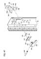
- FIG. 16is an enlarged, fragmentary view of FIG. 13 , showing one of the caster bracket assemblies exploded from the frame assembly;
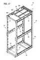
- FIG. 17is similar to FIG. 1 , with the addition of horizontal panels attached to an upper end of the frame assembly;
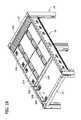
- FIG. 18is an enlarged, fragmentary view of FIG. 17 showing the horizontal panels
- FIG. 19is an enlarged, fragmentary view of FIG. 18 showing a front horizontal panel, with a middle horizontal panel removed from the frame assembly;
- FIG. 20is an enlarged perspective of the front horizontal panel
- FIG. 21is an enlarged, fragmentary top plan view of the horizontal panel showing a retractable pin assembly in an extended (locked) position;
- FIG. 22is similar to FIG. 21 , with the retractable pin assembly in a retracted (unlocked) position;
- FIG. 23is an enlarged, fragmentary bottom plan view of the horizontal panel showing a retractable pin assembly in an extended (locked) position;
- FIG. 24is similar to FIG. 23 , with the retractable pin assembly in a retracted (unlocked) position;
- FIG. 25is an enlarged, bottom perspective of the retractable pin assembly
- FIG. 26is an enlarged, top perspective of the retractable pin assembly
- FIG. 27is a sectional view of the retractable pin assembly
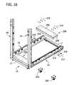
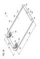
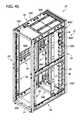
- FIG. 28is a front perspective of the equipment rack having various components removed for clarity in illustrating brackets
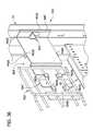
- FIG. 29is a section of the equipment rack of FIG. 28 taken in the plane including line 29 - 29 in FIG. 28 ;
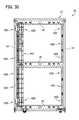
- FIG. 30is a section of the equipment rack taken in the plane including line 30 - 30 in FIG. 28 ;
- FIG. 31is a front perspective of a first embodiment of a bracket, a snap fit retainer being shown separated from a bracket body;
- FIG. 32is a fragmentary perspective of the bracket of FIG. 31 shown in registration with a mounting area of the equipment rack;
- FIG. 33is a fragmentary perspective similar to FIG. 32 but showing the bracket mounted on the mounting area;
- FIG. 34is a fragmentary section taken in the plane including line 34 - 34 of FIG. 33 ;
- FIG. 35is a fragmentary section taken in the plane including line 35 - 35 of FIG. 33 ;
- FIG. 36is a fragmentary perspective of a bracket of a second embodiment mounted on a mounting area and holding a horizontal tray;
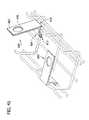
- FIG. 37is a fragmentary elevation of a bracket of a third embodiment mounted on a mounting area and holding a lower end of a vertical tray;
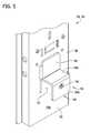
- FIG. 38is a fragmentary elevation of a bracket of the third embodiment mounted on a mounting area and holding an upper end of the vertical tray;
- FIG. 39is similar to FIG. 1 , with the addition of one embodiment of cable retainer gates secured to a wire basket;
- FIG. 40is an enlarged, fragmentary perspective of two cable retainer gates secured to the wire basket
- FIG. 41is similar to FIG. 40 , showing one of the cable retainer gates rotated on the wire basket;
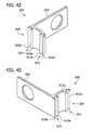
- FIG. 42is an enlarged perspective of the cable retainer gate
- FIG. 43is an enlarged perspective, taken in a different vantage point, of the cable retainer gate
- FIG. 44is an elevational view of the cable retainer gate
- FIG. 45is similar to FIG. 1 , including mounting rails, caster bracket assemblies, horizontal panels for the upper end of the frame assembly, tool-free mounting brackets, and cable retainer gates;
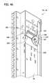
- FIG. 46is an enlarged, fragmentary perspective of a mounting rail with another embodiment of a clamp on the mounting rail;
- FIG. 47is similar to FIG. 46 , with components of the mounting rail shown exploded;
- FIG. 48is an enlarged cross section at the upper end of the mounting rail showing the clamp in an unlocked position
- FIG. 49is similar to FIG. 48 , with the clamp in the locked position.
- an equipment rackis generally indicated at reference numeral 10 .
- the equipment rack 10may be part of or otherwise be referred to as an equipment cabinet or enclosure.
- the illustrated equipment rack 10is particularly suitable for mounting equipment, such as but not limited to computer servers, routers, switches, data storage devices, and/or power supplies (not show), thereon.
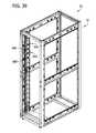
- the illustrated equipment rack 10is generally in the form of a cabinet-type equipment rack, including a frame assembly, generally indicated at 12 .
- the frame assembly 12has generally rectangular footprint and a front, a back, a left side, a right side, an upper end and a lower end.
- the frame assembly 12comprises four uprights, generally indicated at 14 (e.g., vertical supports or struts), at four corners of the frame assembly.
- the four uprights 14may be identical in structure, as explained in more detail below.
- the frame assembly 12also includes upper and lower side braces, generally indicated at 16 (e.g., horizontal supports or struts), secured to, extending between, and interconnecting adjacent uprights at the left and right sides of the frame assembly adjacent the respective upper and lower ends of the frame assembly.
- the upper and lower side braces 16may be identical in structure, although, for reasons that will be apparent below, the upper side braces may be oriented upside-down (i.e., inverted) relative to the lower side braces.
- Upper front, upper back, lower front, and lower back braces, each indicated at 17are secured to, extend between, and interconnect adjacent uprights 14 at the front and back of the frame assembly 12 adjacent the respective upper and lower ends of the frame assembly.
- These braces 17may be identical to one another and of a different structure than the upper and lower side braces 16 .
- the frame assembly 12further includes intermediate left and right side braces 18 located between the upper and lower braces 16 and secured to, extending between, and interconnecting adjacent uprights 14 at the left and right sides of the frame assembly.
- the intermediate side braces 18may be identical in structure to the upper and lower side braces 16 , as illustrated. It is understood that in one or more embodiments, one or more of the uprights 14 and/or the braces 16 , 17 , 18 may have a structure other than illustrated without necessarily departing from the scope of the claims.
- the uprights 14may be formed from sheet metal, having a thickness from 10 gauge to 20 gauge, for example, or other suitable thicknesses.
- the uprights 14may be formed from other materials suitable for providing structural support to the equipment rack 10 .
- the braces 16 , 17 , 18may be formed from sheet metal, having a thickness from 10 gauge to 20 gauge, for example, or other suitable thicknesses.
- the braces 16 , 17 , 18may be formed from other materials suitable for providing structural support to the equipment rack 10 .
- the braces 16 , 17 , 18may be secured to the corresponding uprights 14 in suitable ways, including but not limited to, mechanically fastening (e.g., screws, bolts, nuts), welding, brazing, soldering, and/or adhesion.
- the upper braces 16 , 17may be secured to one another to form an upper frame member (e.g., rectangular frame member), and the lower braces may be secured to one another to form a lower frame member (e.g., rectangular frame member).
- the corresponding braces 16 , 17may be secured to one another in suitable ways, including but not limited to, mechanically fastening (e.g., screws, bolts, and nuts), welding, brazing, soldering, and/or adhesion.
- upper and/or lower panelsmay be secured to the respective upper and lower ends of the frame assembly 12 .
- Left and right panelsmay be secured to the respective left and right sides of the frame assembly 12 .
- a back panel(not shown) may be secured to the back of the frame assembly 12 .
- a door(not shown) may be attached to the front of the frame assembly 12 to allow access (e.g., permitted access) to the equipment in the rack.
- the equipment rack 10further includes at least one pair of mounting rails configured to mount the equipment within the rack.
- the equipment rack 10includes a first pair of mounting rails including left and right mounting rails (e.g., front mounting rails), each generally indicated at reference numeral 24 , and a second pair of mounting rails including left and right mounting rails, each generally indicated at reference numeral 26 .
- the left mounting rails 24 , 26are attached to and extend between the left upper brace 16 and the left lower brace 16 .
- the right mounting rails 24 , 26are attached to and extend between the right upper brace 16 and the right lower brace 16 .
- the mounting rails 24 , 26are selectively, individually movable along the left and right upper and lower braces 16 to adjust the positions of the mounting rails along the lengths of the corresponding braces. In effect, the mounting rails 24 , 26 are selectively movable forward and backward in the equipment rack 10 .
- each mounting rail 24 , 26may be substantially identical to facilitate modularity of the rack 10 .
- each mounting rail 24 , 26includes an elongate rail body, generally indicated at 30 (e.g., a vertical strut), having a length extending between upper and lower ends thereof, and at least one releasable clamp, generally indicated at 34 , configured to facilitate clamping of the mounting rail in a selected position relative to at least one of the corresponding upper and lower left and right braces 16 and unclamping of the mounting rail from the at least one of the corresponding upper and lower left and right braces to allow movement (e.g., sliding movement) of the mounting rail along the corresponding brace.
- elongate rail bodygenerally indicated at 30 (e.g., a vertical strut)
- at least one releasable clampgenerally indicated at 34 , configured to facilitate clamping of the mounting rail in a selected position relative to at least one of the corresponding upper and lower left and right braces 16 and unclamping of the mounting rail from the at least
- the rail body 30in generally in the form of a strut including a web 36 with a generally planar shape, and opposite first and second L-shaped flanges, generally indicated at 38 , 40 , respectively, extending from opposites sides of the web.
- the L-shaped flanges 38 , 40have first portions 38 a , 40 a , respectively, extending inward, relative to the rack 10 , at generally perpendicular angles from an inner surface 36 a of web 36 to form a channel shaped-strut, and second portions 38 b , 40 b , respectively, at the ends of the respective first portions extending laterally away from the web.
- a lip 48extends inward, relative to the rack 10 , from the second portion 38 b of the L-shaped first flange 38 , such that the lip 48 is generally parallel to the first portion 38 a of the L-shaped flange and perpendicular to the web 36 .
- the web 36 , the first and second L-shaped flanges 38 , 40 , respectively, and the lip 48each define a plurality of mounting openings 50 spaced apart along its length.
- the mounting openings 50are selectively used to facilitate mounting of the equipment in the rack 10 and/or for connecting other components and structures to the mounting rails 24 , 26 .
- an outer surface 36 b of the web 36engages (i.e., contacts) inner surfaces of the respective upper and lower braces 16 , 18 when the mounting rail 24 , 26 is clamped on the upper and lower braces.
- the strut of the rail body 30may be fabricated from sheet metal, having a thickness from 10 gauge to 20 gauge, for example, or other suitable thicknesses.
- each mounting rail 24 , 26includes two of the clamps 34 , as shown in FIG. 3 .
- each mounting rail 24 , 26includes upper and lower clamps 34 located adjacent respective upper and lower ends of the rail body 30 .
- the upper and lower clamps 34may be identical, although, as illustrated, the upper and lower clamps may have different orientations on the rail body 30 (see, e.g., FIGS. 4 and 5 ).
- Each illustrated clamp 34is selectively configurable between a clamped configuration, to clamp the mounting rail 24 , 26 on the corresponding brace 16 and resist movement of the mounting rail on the corresponding brace, and an unclamped configuration, to allow sliding movement of the mounting rail on the corresponding brace.
- the illustrated clamp 34includes a locking mechanism to releasably lock the clamp in the clamping configuration.
- the locking mechanismmay be a cam lock, as explained below. It is understood that other types of clamps, including other ways of locking the clamp, do not necessarily depart from the scope of the claims.
- the clamp 34includes a clamp arm, generally indicated at 56 , extending outward from the outer surface 36 b of the web 36 , and a lever, generally indicated at 60 , at the inner surface 36 a of the web configured to move the clamp arm toward and away from the outer surface of the web.
- the illustrated clamp arm 56is configured to engage (e.g., contact) the corresponding one of the upper and lower braces 16 .
- the clamp arm 56 of the upper clampis arranged and configured to engage (e.g., contact) a lower portion, generally indicated at 64 , of the upper brace 16 .
- the clamp arm 56 of the lower clamp 34is arranged and configured to engage (e.g., contact) an upper portion, generally indicated at 66 , of the lower brace 16 .
- the illustrated clamp arm 56 of each clampis L-shaped (i.e., generally L-shaped) having a first clamp portion 56 a extending outward from (e.g., generally perpendicular to) the outer surface 36 b of the web 36 , and a second clamp portion 56 b extending from (e.g., generally perpendicular to) the first clamp portion.
- the clamp arm 56 of the upper clamp 34is arranged such that the second clamp portion 56 b extends upward from (e.g., generally perpendicular to) the first clamp portion 56 a , as shown in FIG.
- the clamp arm 56 and the outer surface 36 b of the web 36define an upper channel 70 ( FIG. 4 ) sized and shaped to receive the lower portion 64 of the upper brace 16 (as shown in FIG. 10 ).
- the clamp arm 56 of the lower clamp 34is arranged such that the second clamp portion 56 b extends downward from (e.g., generally perpendicular to) the first clamp portion 56 a .
- the clamp arm 56 and the outer surface 36 b of the web 36define a lower channel 72 ( FIG. 5 ) sized and shaped to receive the upper portion 66 of the lower brace 16 (as shown in FIG. 11 ).
- each clamp 34includes a detent projection 76 extending into the corresponding channel 70 , 72 .
- each clamp 34may function as and be referred to as a detent because of the detent projection 76 . It is understood that the clamp 34 may not include the detent projection 76 and may not function as a detent.
- the detent projection 76extends from the second portion 56 b of the clamp arm 56 , although the detent projection may project from another portion of the clamp arm, such as the first portion 56 a .
- the illustrated detent projection 76comprises a nub or boss or other projecting component.
- each of the upper and lower side braces 16includes a web 84 , upper and lower flanges 86 extending outward from (e.g., perpendicular to) the web, and upper and lower inturned lips 88 extending inward, relative to the web, from the upper and lower side flanges 16 , respectively.
- the upper and lower side braces 16comprise generally C-shaped struts.
- the upper flanges 86 and upper lips 88define the upper portion 66 of the lower side braces 16
- the lower flanges 86 and the lower lips 88define the lower portions 64 of the upper side braces 16 .
- at least one of the upper and lower lips 88defines the detent-receiving recesses 82 .
- the detent projection 76is configured to be received in any selected one of the plurality detent-receiving recesses 82 to facilitate locking of the mounting rail 24 , 26 to the corresponding brace 16 and configured to be selectively removed from the detent-receiving recess to facilitate unlocking of the mounting rail from the corresponding brace.
- At least one of the lower and upper portions 64 , 66 of the upper and lower side braces 16defines a track on which the clamp arm 56 is selectively slidable to adjust the position of the mounting rail 24 , 26 in the rack 10 .
- the lever 60includes a cam 90 (e.g., a cylindrical cam) pivotally coupled to the clamp arm 56 , and a lever arm 92 secured to the cam for manually actuating rotation of the cam about a rotational axis RA relative to the clamp arm and the rail body 30 .
- the lever 60includes a trunnion 94 (e.g., a pivot pin) defining the rotational axis RA and rotatably coupled to a trunnion bearing 98 secured to the clamp arm 56 .
- the trunnion bearing 98includes spaced apart bearing arms (indicated by same reference numeral 98 ) extending inward relative to the clamp arm 56 through spaced apart slots 100 in the web 36 of the mounting rail 24 , 26 .
- the bearing arms 98define trunnion-receiving openings 102 in which the trunnion 94 is rotatably received at the inner side of the web 36 .
- the cam surface of the cam 90has an eccentric circumference having a non-uniform diameter about the rotational axis RA.
- the cam 90rotates about the rotational axis RA and a circumferential portion of the cam surface having a relatively larger radius r 1 with respect to the rotational axis engages (i.e., contacts) and rides on (e.g., pushes against) the inner surface 36 a of the web to move the clamp arm 56 toward the outer surface 36 b of the web.
- the lever arm 92is rotated away the web 36 to an unlocked position, as shown in FIG.
- the one or more pairs of mounting rails 24 , 26are connected to the upper and lower side braces 16 .
- the clamps 34are configured in the unclamped configuration (e.g., the circumferential portion of the cam surface having the relatively smaller radius r 2 is in engagement with and/or facing the inner surface 36 a of the web 36 ).
- the lower portions 64 of the upper side braces 16e.g., the lower flanges 86 and the lower lips 88 of the braces) are inserted into the upper clamp channels 70 of the mounting rails 24 , 26 .
- the upper portions 66 of the lower braces 16are inserted into the lower clamp channels 72 of the mounting rails 24 , 26 .
- the mounting rails 24 , 26are slidable along the upper and lower side braces 16 (e.g., the clamp arms 56 slide along the braces) to selected front-to-back positions within the equipment rack 10 and relative to the lengths of the side braces.
- the lever arms 92 of the clamps 34are manually rotated relative to the corresponding clamp arms 56 and rail bodies 30 , such as rotated toward the web 36 of the rail body (e.g., downward), to actuate rotation of the cam 90 .
- the circumferential portion of the cam surface having the relatively larger radius r 1engages (e.g., contacts) and rides on (e.g., pushes against) the inner surface 36 a of the web 36 .
- This camming actionmoves the clamp arm 56 toward the corresponding upper and lower portions 64 , 66 of the respective upper and lower side braces 16 , whereupon the clamp arm 56 clamps the mounting rail 24 , 26 to the corresponding side brace 16 such that the inner surface 84 a of the web 84 of the brace contacts the outer surface 36 b of the web 36 of the rail body 30 .
- the cam 90is in a locked position to inhibit unintentional unclamping of the clamp 34 .
- the detent projection 76 on the clamp arm 56enters one of the detent-receiving recesses 82 (broadly, forms a mating connection) to further inhibit unintentional movement of the mounting rail 24 , 26 from its selected position.
- the detent-receiving recessesmay be spaced apart from one another at uniform intervals along the lengths of the braces 16 , including but not limited to, about 10 mm intervals.
- the positions of the mounting rails 24 , 26can be quickly and easily repositioned in the rack 10 by unclamping the mounting rails.
- the lever arms 92 of the upper and lower clamps 34are manually rotated away from the web 36 of the rail body 30 (e.g., upward), to actuate rotation of the corresponding cams 92 , whereupon the circumferential portions of the cam surfaces having the larger radii r 1 disengage from the inner surface 36 a of the web 36 to allow the clamp arms 56 to move away from the upper and lower portions 64 , 66 of the respective lower and upper side braces 16 and unclamp the mounting rail.
- the mounting rail 24 , 26With the mounting rail 24 , 26 unclamped from the brace 16 , the mounting rail is allowed to slide along the corresponding brace.
- the detect projections 76 on the clamp arms 56are at least partially outside the detent-receiving recesses 82 to further allow sliding movement of the mounting rail 24 , 26 along the corresponding brace 16 .
- FIGS. 46-49another embodiment of a clamp is generally indicated at reference numeral 134 .
- This clamp 134is similar to the first clamp 34 , with differences being described hereinafter.
- the clamp 134may be used in the same way as described above with respect to the first clamp 34 .
- the present clamp 134includes a clamp arm, generally indicated at 156 , and a lever, generally indicated at 160 .
- the clamp arm 156 and the lever 160function in the same manner as the respective clamp arm 56 and the lever 60 of the first clamp 34 .
- the clamp arm 156is configured to engage (e.g., contact) the corresponding one of the upper and lower braces 16 .
- the clamp arm 156is generally L-shaped having a first clamp portion 156 a and a second clamp portion 156 b , similar to the first clamp arm 56 .
- the lever 160includes a cam 190 (e.g., a cylindrical cam) pivotally coupled to the clamp arm 156 , and a lever arm 192 secured to the cam for manually actuating rotation of the cam about a rotational axis RA 2 relative to the clamp arm and the rail body 30 .
- the cam surface of the cam 190has an eccentric circumference having a non-uniform diameter about the rotational axis RA 2
- the lever 160includes a trunnion 194 (e.g., a pivot pin) defining the rotational axis RA 2 and rotatably coupled to a trunnion bearing 198 secured to the clamp arm 156 .
- the trunnion bearing 198includes spaced apart bearing arms (indicated by same reference numeral 198 ).
- the present clamp 134includes a thrust plate 104 disposed between the cam 190 and the inner surface 36 a of the web 36 .
- the thrust plate 104increases a clamping force of the clamp 134 on the brace 16 .
- the cam 190engages and rides on a bearing surface 105 of the thrust plate 104 having a shape generally corresponding to the shape of the surface of the cam 190 (e.g., the bearing surface 105 defines a recess in which the cam is received).
- the thrust plate 104is captured by the trunnion bearing 198 to maintain its position between the cam 190 and the inner surface 36 a of the web 36 .
- the trunnion bearing 198is slidable inward and outward relative to the thrust plate 104 during locking and unlocking of the clamp 134 .
- the lever arm 192is rotated toward the web 136 to a cam-locked position, as shown in FIG. 49 for example, so that the cam 190 rotates about the rotational axis RA 2 and a circumferential portion of the cam surface having a relatively larger radius with respect to the rotational axis engages (i.e., contacts) and rides on (e.g., pushes against) the bearing surface 105 of the thrust plate 104 to move the clamp arm 156 toward the outer surface 36 b of the web 36 .
- One or more bumpers 106engages the inner surface 36 a of the web 36 and may compress as the clamp arm 156 clamps on the brace 16 .
- the illustrated embodimentalso includes a bumper 108 (e.g., a resiliently compressible bumper) attached to a body component 156 c of the clamp arm 156 that engages the outer surface 36 b of the web 36 may compress as the clamp arm 156 clamps on the brace 16 .
- the lever arm 192is rotated away the web 36 to an unlocked position, as shown in FIG.
- the cam 190rotates about the rotational axis RA 2 and a circumferential portion of the cam surface having the relatively larger radius disengages from (e.g., is no longer in contact with) the bearing surface 105 of the thrust plate 104 and a circumferential portion of the cam surface having a relatively smaller radius with respect to the rotational axis RA 2 rides on the bearing surface 105 of the thrust plate 104 to allow the clamp arm 156 to move away from the outer surface 36 b of the web 36 .
- the lever 192 of the clamp 134includes a stop 109 that inhibits the lever from rotating beyond a selected rotational position (e.g., beyond about 90 degrees from its locked position).
- the stop 109projects outward from the cam surface of the cam 190 and engages the thrust plate 104 when the lever 192 is rotated to about 90 degrees from its locked position to inhibit further rotation of the lever.
- the equipment rack 10may include at least one caster bracket, generally indicated at 200 , for mounting casters 202 (broadly, wheels) at the lower end of the frame assembly 12 . Together, the caster bracket 200 and the casters 202 form a caster bracket assembly.
- the equipment rack 10includes two caster brackets 200 : a front caster bracket and a back caster bracket.
- the caster brackets 200may be substantially identical to facilitate modularity of the rack 10 .
- the caster bracket 200has a generally rectangular footprint, including generally planar base 206 and front, back, left, and right side walls 208 extending downward from the corresponding sides of the base.
- the caster bracket 200is attached to the frame assembly 12 adjacent the lower end thereof. In the illustrated embodiment, the caster bracket 200 extends between the inner surfaces 36 a of the lower left and right braces 16 .
- the left and right side walls 208 of the caster bracket 200are attached to the left and right braces 16 , respectively.
- a first set of mechanical fasteners 210e.g., screws or bolts and nuts
- a second set of mechanical fasteners 212e.g., screws or bolts and nuts
- the fasteners 212are inserted through openings 214 in the respective left and right walls 208 and openings 216 in the respective webs of the lower braces 16 .
- the caster brackets 200may be attached to the lower side braces 16 and/or the frame assembly 12 in other ways.
- Casters 202are attached to the lower surface of the caster bracket body 206 using suitable fasteners 218 (e.g., screws or bolts and nuts) or in other ways.
- At least one of the caster brackets 200is selectively attachable to the lower right and left braces 16 at a plurality of locations along the lengths of the braces to adjust the locations of the caster bracket in a front-to-back direction.
- this adjustable location of the rear caster bracket 200allows the rear caster bracket to be attached to the frame assembly 12 such that the back side wall 208 of the caster bracket is spaced apart, in a forward direction, from the lower back brace 17 (i.e., spaced from the back side of the frame assembly) to define a gap 220 therebetween. Cables, wires, and/or other components may be fed through the gap 220 to outside the rack 10 .
- the equipment rack 10may include one or more horizontal panel assemblies, each generally indicated at reference numeral 300 , secured to one or both of the upper end and the lower end of the frame assembly 12 .
- the equipment rack 10includes a plurality of upper horizontal panel assemblies 300 (e.g., 3 upper horizontal panel assemblies) secured to the upper end of the frame assembly 12 , forming a ceiling of the rack. It is understood that the horizontal panel assemblies 300 may be secured to the lower end of the frame assembly 12 to form a floor of the equipment rack 10 .
- the illustrated horizontal panel assemblies 300are modular in that the horizontal panel assemblies can be arranged in different configurations at the lower end and/or the upper end of the frame assembly 12 , as explained in more detail below. Moreover, the horizontal panel assemblies 300 may be secured to the frame assembly 12 in an inverted orientation, as explained in more detail below.
- Each horizontal panel assembly 300includes a horizontal panel, generally indicated at 302 .
- the horizontal panel 302includes panel body 304 with opposite upper and lower faces, and opposite left and right end walls 306 extending downward from respective left and right sides of the panel body.
- the panel body 304may be generally planar with a rectangular footprint.
- the illustrated horizontal panels 302also include front and back flanges 310 extending downward from respective front and back sides of the panel body 304 .
- the flanges 310add strength and rigidity to the horizontal panels 300 .
- the horizontal panels 302are arranged front to back to form the ceiling and/or floor of the rack 10 . As shown in FIG.
- each horizontal panel 302has a length L 1 extending between the opposite left and right end walls 306 and a width W 1 extending between the opposite front and back flanges 310 .
- the lengths L 1 of the horizontal panels 302may be uniform, while the widths may vary by predetermined increments, such as 100 mm increments.
- the horizontal panels 302may be formed as a unitary structure.
- the horizontal panels 302may be fabricated from sheet metal, having a thickness from 10 gauge to 20 gauge, for example, or other suitable thicknesses.
- one or more embodiments of the horizontal panel assembly 300may include egress/ingress ports 314 through which cables/wires may exit/enter the rack 10 .
- the illustrated egress/ingress ports 314are provided on the panel body 302 .
- the egress/ingress ports 314include, but are not limited to, brushes, flap seals (e.g., rubber flaps), and other components generally known in the art.
- the horizontal panel 302 illustrated in FIG. 20is a solid panel having no egress/ingress ports for through which cables/wires may exit/enter the rack 10 .
- One or more of the horizontal panels 302may be of other configurations and have other features.
- each horizontal panel assembly 300further includes at least one retractable pin 320 configured to releasably secure the horizontal panel assembly to the frame assembly 12 .
- each horizontal panel assembly 300includes a pair of the retractable pins 320 at one of the end walls 306 of the horizontal panel 302 (e.g., the left end wall), and a pair of non-retractable pins 324 at the other end wall (e.g., the right end wall; FIG. 20 ) of the horizontal panel 302 .
- the pins 320 , 324extend (or at extendable) laterally outward from the corresponding end walls 306 and are configured to be inserted into selected ones of pin-receiving recesses 327 ( FIG.
- the non-retractable pins 324are fixedly secured (e.g., welded, soldered, fastened, etc.) to the corresponding end wall 306 .
- the retractable pins 320extend or are extendable through pin openings 325 in the associated end wall 306 and are movable inward relative to the horizontal panel 302 to facilitate securement of the horizontal panel assemblies 300 to the frame assembly 12 .
- the non-retractable pins 324may be replaced with other types of connectors, including the retractable pins 320 , or other suitable connectors.
- each retractable pin 320is part of a retractable pin assembly, generally indicated at 326 .
- the retractable pin assembly 326comprises a slide, generally indicated at 328 , which is secured to the retractable pin 320 .
- the slide 328is slidably coupled to the horizontal panel 302 (e.g., at the lower surface of the panel body 304 ).
- the slide 328includes a slide base 332 having opposite sides slidably captured between opposing L-shaped track arms 334 extending from the lower surface of the panel body 304 and defining a track in which the slide is slidably captured.
- the slide 328also includes a lower handle 338 accessible at the lower face of the panel body.
- the first handle 338comprises a tab configured to be gripped or contacted or otherwise controlled to slidably move the slide 328 in the track.
- the illustrated slide 328also includes an upper handle 340 accessible at the lower face of the panel body 304 through an access opening 342 formed in the panel body.
- the upper handle 340is defined by a finger cavity 344 extending in the slide base 332 .
- the retractable pin assembly 326is movable (e.g., slidable) between an extended position (or locked position), as shown in FIGS. 21 and 23 , in which the pin 320 extends laterally outward from the corresponding end wall 306 of the horizontal panel 302 an extended distance d 1 , and a retracted position (or unlocked position), in which the pin does not extend outside the horizontal panel 302 (as shown) or extends laterally outward from the end wall a retracted distance (not shown) that is less than the extended distance.
- the retractable pin assembly 326is releasably lockable in the extended position.
- the retractable pin assembly 326includes a detent 348 on the slide base 332 .
- the detent 348is resiliently deflectable relative to the slide base and includes a detent projection 350 (e.g., a nub) that is receivable in a detent-receiving opening 352 in the horizontal panel 302 (e.g., panel body 304 ) when the retractable pin assembly 326 is in the extended position ( FIGS. 21 and 23 ).
- the illustrated detent 348is cantilevered to the slide base 332 to resiliently deflect.
- the slide 328includes a stop 354 configured to contact an edge of the access opening 342 to restrict further inward sliding of the retractable pin assembly 326 when the retractable pin assembly 326 is in the retracted position.
- the slide 328may be formed as an integral, one-piece component.
- the slide 328may be formed from plastic or other material.
- the retractable pin 320may be formed from metal or other rigid material.
- the slide 328may be overmolded on the pin 320 . Other ways for securing the pin 320 to the slide 328 are possible.
- the retractable pin assemblies 326are disposed in the retracted positions, as shown in FIGS. 22 and 24 , for example, and the non-retractable pins 324 are first inserted into the selected pin-receiving recesses 327 of one of the upper and/or lower braces 16 . With the non-retractable pins 324 in the selected pin-receiving recesses 327 , the retractable pin assemblies 326 are moved to the extended (or locked) positions such that the retractable pins 320 enter the selected ones of the pin-receiving recesses 327 in the other, opposing upper and/or lower braces 16 .
- the retractable pin assembly and the pin-receiving recess 327 in the brace 16together constitute a releasable latch or releasable latching mechanism.
- either the lower handles 338 or the upper handles 340may be manually grasped to impart sliding movement of the retractable pin assemblies 326 .
- the detents 348resiliently rebound as the detent projections 350 enter the detent-receiving openings 352 in the horizontal panel 302 (e.g., panel body 304 ) to releasably lock the retractable pin assemblies 326 in the extended positions.
- the retractable pin assemblies 326are moved to the retracted (or unlocked) positions such that the retractable pins are withdrawn from the pin-receiving recesses 327 in the upper and/or lower braces 16 .
- the detent projections 350contact respective edges of the detent-receiving openings 352 and ride on the panel body 304 , whereupon the detents 348 resiliently deflect.
- the stops 354inhibit the retractable pin assemblies 326 from over retracting.
- the horizontal panel assemblies 300are configured to allow the panel assembly to be secured to the frame assembly 12 in a non-inverted (i.e., upside-up) or inverted orientation (i.e., upside-down).
- the front horizontal panel assembly 300is secured to the frame assembly 12 in the inverted orientation
- the middle horizontal panel assemblyis secured to the frame assembly in the non-inverted orientation.
- this arrangement of adjacent horizontal panel assemblies 300creates a vertical panel opening 370 between adjacent sides (e.g., the back side of the front horizontal panel 302 and the front side of the middle horizontal panel 302 ) of the horizontal panel assemblies 300 .
- the panel opening 370is defined by vertically spaced apart side flanges 310 of the adjacent horizontal panels 302 .
- the flanges 310have suitable widths so that the flanges of adjacent horizontal panels are spaced apart vertically when one of the horizontal panels is inverted.
- a gasket, brush, flap or other structurecan be secured over or adjacent the panel opening 370 .
- the panel opening 370allows for ingress/egress of cables/wires or other components.
- the panel opening 370can also functions as a vent for air within the rack 10 .
- an electrically conductive clip 374may be secured to one or more of the end walls 306 of the horizontal panel 302 .
- the clip 374includes resiliently deflectable jaws for receiving the end wall 306 therebetween.
- the clip 374also includes one or more barbs 378 that contact the adjacent side brace 16 when the horizontal panel assembly 300 is secured to the frame assembly 12 .
- the barbs 378are in electrical contact with the side brace 16 to ground the horizontal panel assembly 300 .
- the barbs 378may be configured to dig into or scrap the side brace 16 to facilitate the electrical connection.
- the equipment rack 10includes various brackets 400 , 400 ′, 400 ′′ mountable on the frame for supporting items in the equipment rack.
- the brackets 400 , 400 ′, 400 ′′are configured to permit convenient installation at various locations on the frame 12 .
- the brackets 400 , 400 ′, 400 ′′are tool-free mounting brackets, i.e., configured for mounting on the frame 12 without requiring the use of a tool.
- two brackets 400 of a first embodimentare mounted on the left rear upright 14 adjacent the respective upper and lower ends of the frame 12 .
- the brackets 400are configured for supporting power distribution units (not shown), among other things.
- two brackets 400 ′ of a second embodimentare mounted on the left front and left rear uprights 14 , respectively.
- the brackets 400 ′are shown holding a tray 410 (e.g., wire formed tray or wire basket, as shown) extending horizontally for supporting cables to facilitate cable management in the equipment rack 10 .
- two brackets 400 ′′ of a third embodimentare mounted on the right front and right rear uprights 14 , respectively.
- the brackets 400 ′′are shown holding a cable support tray or basket 412 extending in a vertical orientation. More or fewer brackets 400 , 400 ′, 400 ′′ can be used, and the brackets can be mounted in other positions and/or orientations, based on the desired configuration of the equipment rack.
- the equipment rack 10is configured to permit mounting of the brackets 400 , 400 ′, 400 ′′ at various locations.
- the brackets 400 , 400 ′, 400 ′′are mountable on the frame 12 , and in particular, on the uprights 14 .
- the uprights 14each have a plurality of predetermined mounting areas 420 spaced at intervals along the height of the uprights. A user can select among the predetermined mounting areas 420 for mounting the brackets 400 , 400 ′, 400 ′′.
- Other mounting locations in the equipment rack 10can be used without departing from the scope of the present invention. Structure forming the predetermined mounting areas 420 will be described in detail below.
- the bracket 400 of the first embodiment mounted adjacent the lower end of the rear left upright 14will now be described in further detail. It will be understood that the other bracket 400 of the first embodiment, mounted on the front left upright 14 , has the same configuration.
- the bracket 400includes a bracket body 430 and a snap fit retainer 432 (separated from the bracket body in FIG. 31 ).
- the bracket body 430may be formed from sheet metal, having a thickness from 10 gauge to 20 gauge, for example, or another suitable thickness.
- the bracket body 430is made of 14 gauge sheet metal bent into the form of the bracket body.
- the snap fit retainer 432can be made of plastic or another suitable material.
- the snap fit retainer 432can be formed integrally with the bracket body 430 without departing from the scope of the present invention.
- the bracket body 430includes a generally rectangular mounting section 434 having a front mounting face 434 A and an opposite rear face 434 B.
- the mounting section 434has a plurality of connectors configured for mounting various items on the bracket 400 .
- the mounting section 434includes key slots 436 positioned in an array including three columns of two key slots. Each column of key slots 436 is configured for receiving connectors (e.g., button connectors) on the rear of a power distribution unit (not shown) for mounting the power distribution unit in the equipment rack 10 .
- the bracket body 430also includes cable tie anchors in the form of T-shaped teeth 438 in an opening in the mounting section 434 . For example, cable ties (not shown) such as various types of straps, etc.
- the bracket body 430includes upper and lower flanges 440 above and below the mounting section 434 , respectively.
- the upper and lower flanges 440extend between left and right ends of the bracket body 430 , extend rearward from the mounting section 434 , and extend transversely with respect to the mounting face 434 A.
- Right ends of the upper and lower flanges 440form limbs 440 A for mounting the bracket on the frame.
- Gaps 442( FIG. 31 ) are provided between the limbs 440 A and the rear face 434 B of the mounting section 434 for receiving a portion of an upright 14 , as will become apparent.
- the bracket body 430includes a connecting flange 444 to the right of the mounting section 434 .
- the connecting flange 444extends between upper and lower ends of the bracket body 430 , extends forward from the mounting section 434 , and extends transversely with respect to the mounting face 434 A.
- the connecting flange 444has a holder in the form of a rectangular opening 444 A for holding the snap fit retainer 432 (see FIG. 32 ).
- the bracket body 430includes a tongue 446 extending to the right transversely from the forward end of the connecting flange 444 .
- the tongue 446extends generally parallel with the mounting face 434 A.
- the tongue 446 , limbs 440 A, and snap fit retainer 432are used for mounting the bracket 400 on the frame 12 .
- the limbs 440 A and the tongue 446can be broadly referred to as protrusions (more broadly, connectors) used for mounting the bracket 400 .
- bracket 400The position and orientation of the features of the bracket 400 as described above are with reference to the configuration and orientation of the bracket as shown in FIG. 31 . It will be understood that the bracket 400 can be mounted in the equipment rack in various orientations, such that components described above as “upper” may instead be “lower,” components described as “right” may instead be “left,” etc., without departing from the scope of the present invention.
- the upright 14includes structure defining the mounting area 420 configured for cooperating with the bracket 400 for mounting the bracket on the upright.
- the mounting area 420 shown in FIG. 32will be described in further detail, with the understanding that the other mounting areas have a similar construction.
- the upright 14has first and second abutments 450 , 452 .
- the first abutment 450defines an outside corner 450 A and has a vertical slot 450 B sized for receiving the tongue 446 of the bracket 400 .
- the second abutment 452defines an outside corner 452 A having relatively small horizontal slots 452 B for receiving the limbs 440 A of the bracket 400 .
- the vertical and horizontal slots 450 B, 452 Bcan be referred to broadly as receivers (more broadly, connectors) for receiving the protrusions (limbs 440 A and tongue 446 ) of the bracket 400 .
- the first and second abutments 450 , 452also include respective abutment surfaces 450 C, 452 C for abutting the connecting flange 444 and the rear face 434 B of the mounting section 434 , respectively.
- the first abutment 450has a lip 450 D adjacent a cavity 460 in the upright 14 configured for receiving the snap fit retainer 432 .
- the snap fit retainer 432has a generally U-shaped body including first and second legs 464 , 466 and a nose 468 connecting proximal ends of the legs.
- the retainerincludes a lever 470 connected to a distal end of the first leg 464 .
- the second leg 466includes first and second barbs 472 having ramps extending outward and distally with respect to the nose 468 and having retaining surfaces facing distally with respect to the nose.
- the first leg 466includes a catch 480 having a ramp extending outward and distally with respect to the nose 468 and having a retaining surface facing distally with respect to the nose.
- the first and second legs 464 , 466are resiliently deflectable with respect to each other to permit temporary deformation of the retainer 432 for installing the retainer on the bracket body 430 and for securing the bracket 400 on the mounting area 420 .
- the retaining surface of the second barb 472engages the bracket body
- the lever 470engages the connecting flange 444 .
- the retaining surface of the second barb 472limits withdrawal of the retainer 432 back out of the opening 444 A in the connecting flange 444 , and the lever 470 abutting the connecting flange limits movement of the retainer farther into the opening.
- FIG. 32the bracket 400 is shown in registration with and ready for mounting on the mounting area 420 .
- the bracket 400is positioned in register with the mounting area 420 , such that the limbs 440 A are in register with the horizontal slots 452 B, the tongue 446 is in register with the vertical slot 450 B, and the snap fit retainer 432 is in register with the lip 450 D.
- the bracket 400When the bracket 400 is in such a position, the bracket can be moved toward the mounting area along a straight movement axis, in the direction in which the limbs 440 A and tongue 446 extend, not only for mating the protrusions (limbs and tongue) with the receivers (horizontal and vertical slots 452 B, 450 B), but also for releasably locking the snap fit retainer 432 on the lip 450 D to secure the protrusions in the receivers, as shown in FIGS. 33-35 .
- the ramp of the catch 480engages the lip 450 D and causes the first leg 464 to increasingly deflect toward the second leg 466 until the catch 480 passes the lip, permitting the first leg to resiliently “snap” to its non-deflected position. This moves the retaining surface of the catch 480 into position for engaging the lip 450 D to limit withdrawal of the bracket 400 from the mounting area 420 . If desired, to remove the bracket 400 from the mounting area 420 , a user can press the lever 470 to deflect the first leg 464 to permit withdrawal of the retainer 432 from the lip 450 D.
- the bracket 400 and mounting area 420are configured to permit convenient tool-free mounting of the bracket on the mounting area.
- the bracket 400is essentially “plugged” into the mounting area 420 , to mate the bracket with the mounting area and create a releasable securing or retaining connection of the bracket on the mounting area in the same motion, in a simple and efficient manner.
- the bracket 400is substantially anchored against pivoting or rotational movement by the engagement of the bracket with the abutments 450 , 452 .
- the tongue 446abuts an inside surface 450 E of the first abutment 450
- the connecting flange 444abuts the first abutment surface 450 C
- the rear face 434 Babuts the second abutment surface 452 C.
- brackets 400 ′ of the second embodimentnoted briefly above with respect to FIGS. 28-29 , will now be discussed.
- the bracket 400 ′ holding a right end of the horizontally extending tray 410is shown mounted on the rear left upright 14 .
- the bracket 400 ′ holding the opposite end of the horizontally extending tray 410has the same construction and is mounted on the front left upright 14 in a similar fashion.
- the bracket 400 ′is similar in many respects to the bracket of the first embodiment described above, and like parts are indicated by the same reference numbers plus a prime designator.
- the bracket 400 ′mounts on the mounting area 420 in the same manner described above.
- the bracket 400 ′includes protrusions in the form of upper and lower limbs 440 A′ that are received in the horizontal slots 452 B and in the form of a tongue 446 ′ that is received in the vertical slot 450 B.
- the bracket 400 ′also includes a snap fit retainer 432 ′ for securing against the lip 450 D.
- the mounting section 434 ′has different connectors.
- the connectors on the mounting sectioninclude an upper set of hooks 482 A and a lower set of hooks 482 B.
- the sets of hooks 482 A, 482 Bare oriented in opposite directions.
- the upper hooks 482 Aextend upward for holding a segment of the horizontal tray 410
- the lower hooks 482 Bextend downward for holding a different segment of the horizontal tray.
- the hooks 482 A, 482 Bhold the respective tray segments against the mounting face 434 A′ of the mounting section 434 ′. Accordingly, the brackets 400 ′ at opposite ends of the tray 410 hold the tray in position for supporting cables in the equipment rack.
- the brackets 400 ′′ of the third embodimentnoted briefly above with respect to FIGS. 28 and 30 , will now be discussed.
- the bracket 400 ′′ holding a lower end of the vertically extending tray 412is shown in FIG. 37
- the bracket 400 ′′ holding an upper end of the vertically extending tray 412is shown in FIG. 38 .
- the brackets 400 ′′are similar in many respects to the brackets of the first and second embodiments described above, and like parts are indicated with the same reference numbers plus a double prime designator.
- the brackets 400 ′′mount at the mounting areas 420 in the same manner described above.
- the bracket 400 ′′includes protrusions in the form of upper and lower limbs 440 A′′ that are received in the horizontal slots 452 B and in the form of a tongue 446 ′′ that is received in the vertical slot 450 B.
- the bracket 400 ′′also includes a snap fit retainer 432 ′′ for releasably locking the bracket 400 ′′ on the mounting area 420 .
- the mounting section 434 ′′has a similar configuration as in the second embodiment.
- the connectors on the mounting sectioninclude an upper set of hooks 482 A′′ and a lower set of hooks 482 B′′. As shown by comparison of FIGS. 37 and 38 , the lower set of hooks 482 B′′ is used for mounting the lower end of the tray 412 , and the upper set of hooks 482 A′′ is used for mounting the upper end of the tray.
- the equipment rack 10includes one or more cable retainer gates, each generally indicated at 600 , attached to one or more wire baskets 410 , 412 (broadly, baskets formed at least partially by wire lattice) mounted on the frame assembly 12 .
- the cable retainer gatesmay be attached at selected locations along the length of the wire basket 412 to retain cables/wires within the wire basket.
- Each cable retainer gate 600may be identical.
- the cable retainer gate 600has a generally L-shaped body including a retainer portion 602 having opposite ends, and a basket-attachment portion, generally indicated at 604 , extending transversely (e.g., generally perpendicular) from one end of the retainer portion and configured to selectively and removably attach the cable retainer gate to a selected one of the side walls of the wire basket 412 .
- the retainer portion 602may be generally planar and have generally rectangular perimeter.
- the retainer portion 602may be generally rigid such that it maintains its generally planar shape to retain cables/wires in the wire basket 412 .
- the retainer portionis generally in the form of a flap or cantilever that extends toward the opposite side wall of the wire basket, across the open channel of the wire basket 412 , adjacent the open side of the channel.
- the basket-attachment portion 604includes first and second snap-fit connector 610 , 612 , respectively, that are spaced apart from one another along the basket-attachment portion and are configured to snap-fit connect to spaced apart wires running along the side wall of the wire basket 412 .
- each snap-fit connector 610 , 612includes a pair of opposing jaws 610 a , 612 a , respectively, defining a channel therebetween for receiving the corresponding wire.
- the channelmay have a generally arcuate shape in cross section.
- the opposing jaws 610 a , 612 aare resiliently deflectable away from one another to allow the wire to enter the channel through the open side, whereupon the jaws rebound to grasp the wire.
- the snap-fit connectors 610 , 612may be of other types in other embodiments.
- the cable retainer gate 600when both of the first and second snap-fit connectors 610 , 612 , respectively, are attached to one of the side walls of the wire basket 412 , the cable retainer gate 600 is generally fixed to the wire basket (i.e., is not movable) so that the cantilevered retainer portion 602 inhibits the cables/wires from falling out the open side of the wire basket. As shown in FIG. 41 , when only the first snap-fit connector 610 is attached to one of the side walls of the wire basket 412 , the cable retainer gate 600 is pivotable or rotatable about the attached wire of the basket.
- the cantilevered retainer portion 602can be pivoted or rotated away from the open side of the wire basket to allow entry or removal of cables/wires from the basket without detaching the cable retainer gate from the basket.
- a finger opening 620is defined by the retainer portion 602 to allow a user to pivot the cable retainer gate 600 by inserting a finger in the opening.
- the retainer portion 602may have a length from about 3 in to about 4 in (e.g., about 3.5 in). Center axes of the snap-fit channels of the first and second snap-fit connectors 610 , 612 may be spaced apart a distance of about 1 in (e.g., 1.05 in) or other distances based on the distance between adjacent side wires of a desired wire basket.
- the cable retainer gate 600may be of other dimensions.
- the cable retainer gate 600is an integrally formed, one-piece component.
- the cable retainer gate 600may be formed from plastic (e.g., ABS plastic material) or other suitable material.
- the cable retainer gate 600may be formed by an injection molding process.
- the equipment rack 10includes one or more of the components described herein above. That is, in one or more embodiments, the equipment rack includes one or more of the following: one or more of the uprights 14 ; one or more of the side braces 16 ; one or more of the mounting rails 26 ; one or more of the caster brackets 200 and/or caster bracket assemblies; one or more of the horizontal panels 300 for either or both the upper end and the lower end of the frame assembly 12 ; one or more of the tool-free mounting brackets 400 , 400 ′, 400 ′′; and one or more of the cable retainer gates 600 . Accordingly, the equipment rack 10 can be thought of as a system. In the embodiment shown in FIG.
- the equipment rackincludes at least one of each of these above-listed components. It is understood that the equipment rack 10 may include less than all of the components.
- each of the above-listed components described hereinmay be provided apart from the equipment rack 10 . That is, each of the components may be sold separately from the equipment rack, such that each of the components may be its own product. Accordingly, the present disclosure contemplates each of the above-listed components may be a separate invention apart from the equipment rack 10 and/or the other components.
Landscapes
- Engineering & Computer Science (AREA)
- Microelectronics & Electronic Packaging (AREA)
- Computer Hardware Design (AREA)
- General Engineering & Computer Science (AREA)
- Patch Boards (AREA)
- Casings For Electric Apparatus (AREA)
- Clamps And Clips (AREA)
- Assembled Shelves (AREA)
- Chemical & Material Sciences (AREA)
- Combustion & Propulsion (AREA)
- Transportation (AREA)
- Mechanical Engineering (AREA)
- Handcart (AREA)
- Connection Of Plates (AREA)
Abstract
Description
Claims (24)
Priority Applications (1)
| Application Number | Priority Date | Filing Date | Title |
|---|---|---|---|
| US15/418,137US10492605B2 (en) | 2016-01-30 | 2017-01-27 | Mounting bracket for equipment rack |
Applications Claiming Priority (2)
| Application Number | Priority Date | Filing Date | Title |
|---|---|---|---|
| US201662289212P | 2016-01-30 | 2016-01-30 | |
| US15/418,137US10492605B2 (en) | 2016-01-30 | 2017-01-27 | Mounting bracket for equipment rack |
Publications (2)
| Publication Number | Publication Date |
|---|---|
| US20170223857A1 US20170223857A1 (en) | 2017-08-03 |
| US10492605B2true US10492605B2 (en) | 2019-12-03 |
Family
ID=59385823
Family Applications (6)
| Application Number | Title | Priority Date | Filing Date |
|---|---|---|---|
| US15/418,181ActiveUS10182651B2 (en) | 2016-01-30 | 2017-01-27 | Panel for equipment rack |
| US15/418,210Active2037-03-17US10448534B2 (en) | 2016-01-30 | 2017-01-27 | Cable retainer gate for retaining cable on wire basket and method of using same |
| US15/418,028Active2037-12-16US10588235B2 (en) | 2016-01-30 | 2017-01-27 | Equipment rack having mounting rails |
| US15/418,072ActiveUS10561038B2 (en) | 2016-01-30 | 2017-01-27 | Equipment rack having mounting brackets |
| US15/418,137Active2037-03-08US10492605B2 (en) | 2016-01-30 | 2017-01-27 | Mounting bracket for equipment rack |
| US15/418,106ActiveUS10357104B2 (en) | 2016-01-30 | 2017-01-27 | Equipment rack having caster brackets |
Family Applications Before (4)
| Application Number | Title | Priority Date | Filing Date |
|---|---|---|---|
| US15/418,181ActiveUS10182651B2 (en) | 2016-01-30 | 2017-01-27 | Panel for equipment rack |
| US15/418,210Active2037-03-17US10448534B2 (en) | 2016-01-30 | 2017-01-27 | Cable retainer gate for retaining cable on wire basket and method of using same |
| US15/418,028Active2037-12-16US10588235B2 (en) | 2016-01-30 | 2017-01-27 | Equipment rack having mounting rails |
| US15/418,072ActiveUS10561038B2 (en) | 2016-01-30 | 2017-01-27 | Equipment rack having mounting brackets |
Family Applications After (1)
| Application Number | Title | Priority Date | Filing Date |
|---|---|---|---|
| US15/418,106ActiveUS10357104B2 (en) | 2016-01-30 | 2017-01-27 | Equipment rack having caster brackets |
Country Status (2)
| Country | Link |
|---|---|
| US (6) | US10182651B2 (en) |
| CA (6) | CA2950839C (en) |
Cited By (3)
| Publication number | Priority date | Publication date | Assignee | Title |
|---|---|---|---|---|
| US20190264719A1 (en)* | 2018-02-27 | 2019-08-29 | Brennan Equipment and Manufacturing Inc. | Compression-Held Bracket |
| US11678451B2 (en) | 2020-05-04 | 2023-06-13 | Panduit Corp. | Data center cabinet |
| US12035501B2 (en) | 2020-05-04 | 2024-07-09 | Panduit Corp. | Data center cabinet |
Families Citing this family (54)
| Publication number | Priority date | Publication date | Assignee | Title |
|---|---|---|---|---|
| WO2009103090A2 (en) | 2008-02-14 | 2009-08-20 | Chatsworth Products, Inc. | Air directing device |
| EP2429272A2 (en) | 2010-09-10 | 2012-03-14 | Chatsworth Products, Inc. | Cable pass-through panel for electronic equipment enclosure |
| US9313927B2 (en)* | 2010-11-08 | 2016-04-12 | Chatsworth Products, Inc. | Header panel assembly for preventing air circulation above electronic equipment enclosure |
| US9955616B2 (en) | 2010-11-08 | 2018-04-24 | Chatsworth Products, Inc. | Header panel assembly for preventing air circulation above electronic equipment enclosure |
| US20140196394A1 (en) | 2013-01-11 | 2014-07-17 | Chatsworth Products, Inc. | Modular thermal isolation barrier for data processing equipment structure |
| US9351427B2 (en) | 2013-12-17 | 2016-05-24 | Chatsworth Products, Inc. | Electronic equipment enclosure |
| US10215944B2 (en)* | 2016-06-30 | 2019-02-26 | Panduit Corp. | Modular fiber optic tray |
| WO2018022721A1 (en) | 2016-07-26 | 2018-02-01 | Chatsworth Products, Inc. | Features for cable managers and other electronic equipment structures |
| US10306981B2 (en)* | 2016-12-02 | 2019-06-04 | Altria Client Services Llc | Universal mounting system (UMS) and method of installing thereof |
| US10334970B2 (en) | 2016-12-02 | 2019-07-02 | Altria Client Services Llc | Adaptive merchandising platform (AMP) mounting system and method of installing thereof |
| US10172255B2 (en) | 2017-01-26 | 2019-01-01 | International Business Machines Corporation | Enhanced rack/cabinet mobility and stability for a server rack |
| US10117348B2 (en)* | 2017-03-09 | 2018-10-30 | International Business Machines Corporation | Cable management bracket |
| WO2018167372A1 (en)* | 2017-03-16 | 2018-09-20 | Spesiaaliasennus Oy | Method and arrangement for forming a wall |
| US10674636B2 (en)* | 2017-05-03 | 2020-06-02 | International Business Machines Corporation | Installation tool for flexible elements |
| WO2019028041A1 (en)* | 2017-07-31 | 2019-02-07 | Milwaukee Electric Tool Corporation | STORAGE DEVICE SYSTEM |
| KR20190000365U (en)* | 2017-08-01 | 2019-02-11 | 네이버비즈니스플랫폼 주식회사 | Rack having scalability and compatibility |
| US10251304B1 (en)* | 2017-09-20 | 2019-04-02 | Mitek Corp,. Inc. | Lightweight electronics rack |
| US10448536B2 (en)* | 2017-12-14 | 2019-10-15 | Aviat U.S., Inc. | Portable rack dolly, retrofit kit and methods of use |
| DE102018100577B4 (en) | 2018-01-11 | 2024-11-28 | Connect Com GmbH | module support system for telecommunications and data processing modules |
| CN111867785A (en) | 2018-01-24 | 2020-10-30 | 米沃奇电动工具公司 | tool storage device |
| US10674627B2 (en)* | 2018-02-08 | 2020-06-02 | Quanta Computer Inc. | Modifiable rack post |
| USD904327S1 (en)* | 2018-04-10 | 2020-12-08 | Fmr Llc | Freestanding blanking panel |
| CN108556884A (en)* | 2018-05-15 | 2018-09-21 | 韩理想 | A kind of communication cable transport device |
| CN110876246B (en)* | 2018-08-31 | 2021-02-26 | 鸿富锦精密电子(天津)有限公司 | Mounting upright post structure, quick-release assembly and server cabinet with quick-release assembly |
| JP7118855B2 (en)* | 2018-10-22 | 2022-08-16 | 河村電器産業株式会社 | rack |
| US11129294B2 (en)* | 2018-11-15 | 2021-09-21 | CFW Investments LLC | Modular rack assembly |
| US10681834B1 (en)* | 2019-03-26 | 2020-06-09 | Quanta Computer Inc. | Removable cable arm bracket |
| US10794533B1 (en) | 2019-05-08 | 2020-10-06 | Phoenix Contact Development and Manufacturing, Inc. | Variable-geometry mounting bracket for a DIN rail |
| CN110250761B (en)* | 2019-05-27 | 2020-12-15 | 烟台职业学院 | Intelligent accounting financial cabinet and using method thereof |
| EP3747312A1 (en)* | 2019-06-05 | 2020-12-09 | Rol Ergo AB | A bar for supporting a table |
| CN114173613A (en)* | 2019-06-06 | 2022-03-11 | 佩格思医疗有限公司 | Bracket mounting for a load |
| CN110337231A (en)* | 2019-06-12 | 2019-10-15 | 和信精密科技(吴江)有限公司 | A connector for cabinet anti-EMI door |
| US11408456B2 (en) | 2019-08-02 | 2022-08-09 | Hoffman Enclosures Inc. | Integral installation aid |
| IL269564B2 (en) | 2019-09-23 | 2023-11-01 | Keter Home & Garden Products Ltd | Sawhorse |
| US11147416B2 (en)* | 2019-10-09 | 2021-10-19 | William Charles Gardner | Free-standing counter framework |
| US11164146B2 (en) | 2019-11-12 | 2021-11-02 | Dell Products L.P. | Inventory identification |
| US11582874B2 (en) | 2020-01-15 | 2023-02-14 | Dell Products L.P. | Interlocking transportation totes |
| US11388836B2 (en)* | 2020-01-15 | 2022-07-12 | Dell Products L.P. | Plastic tote |
| US11576277B2 (en)* | 2020-02-14 | 2023-02-07 | Quanta Computer Inc. | Rack for supporting servers of varying heights |
| US11785734B2 (en)* | 2020-05-04 | 2023-10-10 | Panduit Corp. | Data center cabinet and top caps for a data center cabinet |
| US11765854B2 (en)* | 2020-11-18 | 2023-09-19 | Commscope Technologies Llc | Universal equipment rack for telecommunications cabinets |
| US11818860B1 (en)* | 2020-12-15 | 2023-11-14 | Chatsworth Products, Inc. | Frame structure for electronic equipment enclosure |
| US11622458B1 (en) | 2020-12-15 | 2023-04-04 | Chatsworth Products, Inc. | Brush port assembly and method for installing same |
| US11678456B1 (en) | 2020-12-15 | 2023-06-13 | Chatsworth Products, Inc. | Slidable mounting hardware for electronic equipment enclosure and method for installing same |
| US12048108B1 (en) | 2020-12-15 | 2024-07-23 | Chatsworth Products, Inc. | Caster attachment system using mating features |
| US11920392B1 (en) | 2021-02-02 | 2024-03-05 | Chatsworth Products, Inc. | Electrical bonding door hinges |
| CN113172323A (en)* | 2021-05-17 | 2021-07-27 | 重庆科技学院 | A kind of solder ball welding method for BGA and electromagnetic pulse welding equipment thereof |
| US12227214B2 (en)* | 2021-06-03 | 2025-02-18 | Frazier Industrial Company | Cart assembly system |
| US11979009B2 (en) | 2022-02-25 | 2024-05-07 | Abb Schweiz Ag | Cable tray support apparatus and system |
| US12133351B2 (en)* | 2022-10-26 | 2024-10-29 | Dell Products L.P. | Cable management system for a server rack |
| US20240314964A1 (en)* | 2023-03-14 | 2024-09-19 | Panduit Corp. | Equipment rail with finger mounting bracket |
| US20250151901A1 (en)* | 2023-11-14 | 2025-05-15 | Textron Aviation, Inc. | Rack shelf systems and method for loading payloads into a rack shelf system |
| WO2025151649A1 (en)* | 2024-01-12 | 2025-07-17 | Milwaukee Electric Tool Corporation | Modular systems and components |
| US12096585B1 (en) | 2024-02-14 | 2024-09-17 | Worksite Lighting LLC | Bolt on power |
Citations (181)
| Publication number | Priority date | Publication date | Assignee | Title |
|---|---|---|---|---|
| US935004A (en) | 1908-05-29 | 1909-09-28 | Mogens Farch | Lock mechanism. |
| US1058952A (en) | 1912-09-23 | 1913-04-15 | Forrest T Durner | Latch. |
| US1744457A (en) | 1928-01-24 | 1930-01-21 | Ellingson Elling | Door latch |
| US2124049A (en) | 1937-04-06 | 1938-07-19 | Battista Joseph John | Plant support |
| US2287531A (en) | 1941-05-06 | 1942-06-23 | Ong Sam Lee | Article carrier |
| US3273720A (en) | 1966-09-20 | Storage racks | ||
| US3465895A (en) | 1966-09-20 | 1969-09-09 | Hyman Miller | Storage rack |
| US3469875A (en) | 1967-11-06 | 1969-09-30 | Amerock Corp | Latching assembly |
| US3510010A (en) | 1968-05-16 | 1970-05-05 | Leon J Gasner | Pallet racks |
| US3633774A (en) | 1970-02-06 | 1972-01-11 | William S Lee | Moving method |
| US4154419A (en) | 1978-06-05 | 1979-05-15 | Harter Corporation | Shelf support bracket construction |
| US4258511A (en) | 1979-03-29 | 1981-03-31 | Strain William E | Industrial noise abatement enclosure |
| US4285436A (en) | 1978-12-26 | 1981-08-25 | Speedshelf International, Inc. | Integral locking tab for storage racks |
| US4675723A (en) | 1984-04-27 | 1987-06-23 | Ampex Corporation | Single oscillator PAL generator lock system |
| US4818000A (en) | 1987-12-09 | 1989-04-04 | The Stanley Works | Decorative surface bolt |
| US5028083A (en) | 1990-04-27 | 1991-07-02 | Motorola, Inc. | Latch assembly |
| US5046464A (en) | 1989-04-07 | 1991-09-10 | Nissan Motor Co. | Clamp for ignition cables |
| US5179919A (en) | 1991-11-08 | 1993-01-19 | Mr. Gasket Company | Wire loom mounting |
| US5372262A (en) | 1991-06-28 | 1994-12-13 | Digital Equipment Corporation | Frame assembly for rack-mountable equipment |
| US5463189A (en) | 1993-12-23 | 1995-10-31 | Deneke; Bernard F. | Installation clip device for electrical cables |
| US5534665A (en) | 1994-04-29 | 1996-07-09 | General Motors Corporation | Wiring harness shroud |
| US5728976A (en) | 1996-05-22 | 1998-03-17 | Dek, Inc. | Detachable cover for wire ducts having a living hinge |
| US5730400A (en) | 1995-09-01 | 1998-03-24 | Sigma-Aldrich | Cable tray cover system |
| US5792992A (en) | 1993-12-08 | 1998-08-11 | Zorba Industries, Inc. | Expandable surface raceway for wiring |
| US5806945A (en) | 1995-09-22 | 1998-09-15 | Amco Engineering Co. | Modular enclosure and method |
| EP0871156A2 (en) | 1997-04-07 | 1998-10-14 | Abex Display Systems | Slidable locking system for disengageable panels |
| US5853236A (en) | 1996-10-01 | 1998-12-29 | The Wiremold Company | Desktop raceway |
| US5871115A (en) | 1995-10-27 | 1999-02-16 | Kohn; Albert | Article supporting and dispensing apparatus |
| US5889648A (en) | 1997-07-25 | 1999-03-30 | Storage Technology Corporation | Seismic cabinet |
| US5949246A (en) | 1997-01-28 | 1999-09-07 | International Business Machines | Test head for applying signals in a burn-in test of an integrated circuit |
| US5980008A (en) | 1997-07-16 | 1999-11-09 | Sandusky Cabinets, Inc. | Caster base for cabinets |
| US6021909A (en) | 1998-11-13 | 2000-02-08 | Hewlett-Packard Company | Equipment enclosure rack support rail system |
| US6029586A (en) | 1996-03-07 | 2000-02-29 | Schiavello Commercial Interiors (Vic) Pty Ltd | Desks, tables and workstations |
| US6084180A (en) | 1993-11-15 | 2000-07-04 | Debartolo, Jr.; Joseph V. | Multi-channel duct for power and tel/com conductors |
| US6109625A (en) | 1998-03-13 | 2000-08-29 | Htc Products, Inc. | Mobile base |
| US6123400A (en) | 1996-11-19 | 2000-09-26 | Rittal-Werk Rudolf Loh Gmbh & Co. Kg | Switching cabinet |
| US6162004A (en) | 1997-07-31 | 2000-12-19 | Hanaoka Sharyo Ltd. | Cargo handling system |
| US6174034B1 (en) | 1996-11-19 | 2001-01-16 | Rittal-Werk Rudolf Loh Gmbh & Co. Kg | Kit for a rack with a corner connector for vertical frame pieces |
| US6181549B1 (en) | 1997-06-24 | 2001-01-30 | Dell Products, L.P. | Chassis retaining system for an electronics rack |
| US6238029B1 (en) | 2000-04-11 | 2001-05-29 | Ads, The Power Resource, Inc. | Universal electronics cabinet |
| US6385036B1 (en) | 1999-09-10 | 2002-05-07 | Robert C. Chien | Screwless computer case assembly |
| US20020062540A1 (en) | 2000-11-30 | 2002-05-30 | Yasutaka Nishida | Adjustable plastic retaining clip |
| US6422399B1 (en) | 2000-11-21 | 2002-07-23 | Dell Products L.P. | Rack system and method having tool-less releasable arm assembly |
| US6430782B1 (en) | 2000-06-28 | 2002-08-13 | David Torres | Cigarette lighter clip |
| US6437244B1 (en) | 2000-06-05 | 2002-08-20 | Panduit Corp. | Wiring duct system hinge arrangement |
| US20020172013A1 (en) | 2001-05-15 | 2002-11-21 | Prima Corporation | Method of attaching supports to an electronic equipment cabinet |
| US6515225B1 (en) | 1998-03-16 | 2003-02-04 | Cooper B-Line Limited | Enclosures |
| US20030047345A1 (en) | 2000-06-01 | 2003-03-13 | Bernard William A. | Split fiber cover and raceway fitting |
| US20030062326A1 (en) | 2001-09-28 | 2003-04-03 | Anteneh Guebre-Tsadik | Adjustable four-column rack |
| US6549424B1 (en) | 2002-02-28 | 2003-04-15 | Garmin Ltd. | Electronic equipment module mounting apparatus and method |
| US6554142B2 (en) | 2001-07-27 | 2003-04-29 | Dell Products L.P. | Variable mount rack system arm assembly |
| US6575315B2 (en) | 2001-06-29 | 2003-06-10 | Richard L. Zidek | Display rack with repositionable shelf |
| US6588866B2 (en) | 2001-04-27 | 2003-07-08 | Intel Corporation | Slide rail attachment |
| US20030127815A1 (en) | 2002-01-10 | 2003-07-10 | Hall Donald M. | Wheeled vehicles, racks, casters for vehicles, and wheel and frame construction |
| US6609619B2 (en) | 1999-12-03 | 2003-08-26 | Hewlett-Packard Development Company, L.P. | Methods for retaining and for releasing a rack slide mounted computer enclosure in a rack system |
| US6614665B2 (en) | 2001-04-16 | 2003-09-02 | Adc Telecommunications, Inc. | Cable management bracket for a telecommunications rack |
| US6615992B1 (en) | 2002-03-11 | 2003-09-09 | Hewlett-Packard Development Company L.P. | Adjustable rackmount assembly |
| US20040001758A1 (en) | 2002-06-26 | 2004-01-01 | Hai Liang | Lockable quick-release blade assembly for ceiling fans |
| US20040016713A1 (en) | 2002-04-01 | 2004-01-29 | Brendan Wyatt | Corner post and manufacturing process for making same |
| US20040065459A1 (en) | 2002-10-04 | 2004-04-08 | Legrand S.P.A. | Protection member for a mesh cable tray, and a tray including said member |
| US6726164B1 (en) | 2001-04-26 | 2004-04-27 | Central Industrial Supply, Company, Inc. | Mounting bracket having a tapered plunger latch |
| US20040120106A1 (en) | 2002-12-20 | 2004-06-24 | Searby Tom J | Transformable computer and system and method incorporating same |
| US6769551B2 (en) | 2002-07-26 | 2004-08-03 | Dell Products L.P. | System and method for utilizing non-dedicated rack space |
| US6773080B2 (en) | 2002-12-06 | 2004-08-10 | King Slide Works, Co., Ltd. | Bracket device for a track assembly |
| US20040189161A1 (en) | 2003-03-28 | 2004-09-30 | Davis Brooks I. | Zero rack unit space utilization |
| US20040217073A1 (en) | 2003-05-01 | 2004-11-04 | Dobler Karl J. | System and method for utilizing a tool-less rail in a rack |
| US6835891B1 (en) | 2003-11-05 | 2004-12-28 | Adc Telecommunications, Inc. | Cover for cable trough |
| US6840388B2 (en) | 2002-10-28 | 2005-01-11 | Hewlett-Packard Development Company, L.P. | Tool-less rack mounting system |
| US20050017608A1 (en) | 2003-07-25 | 2005-01-27 | Kuo-Chih Lin | Computer enclosure incorporating hood fastener |
| US20050023943A1 (en) | 2003-07-29 | 2005-02-03 | Chen-Lu Fan | Computer enclosure with latch device |
| US6865774B2 (en) | 2002-07-01 | 2005-03-15 | Illinois Tool Works Inc. | Caster device |
| US6866154B2 (en) | 2002-12-03 | 2005-03-15 | Dell Products L.P. | Tool-less attachment bracket |
| US20050077804A1 (en) | 2001-09-26 | 2005-04-14 | Heine Altena | Switchgear cabinet |
| US6883282B1 (en) | 2002-12-31 | 2005-04-26 | Newhart, Iii Russell G. | Siding board and conduit holding system |
| US6902069B2 (en) | 2002-10-23 | 2005-06-07 | Dell Products L.P. | System and method for rack cable management |
| US20050145410A1 (en) | 2003-11-26 | 2005-07-07 | Yazaki Corporation | Locking structure for protector and wire harness |
| US6917518B2 (en) | 2002-10-25 | 2005-07-12 | Hon Hai Precision Ind. Co., Ltd. | Computer enclosure having engaging device |
| US6916986B1 (en) | 2004-05-05 | 2005-07-12 | Adc Telecommunications, Inc. | Hinge for cable trough cover |
| US20050156493A1 (en) | 2003-12-30 | 2005-07-21 | Shun-Ho Yang | Bracket positioning structure for a slide |
| US7012808B2 (en) | 2002-12-20 | 2006-03-14 | Hewlett-Packard Development Company, L.P. | Multi-configurable telecommunications rack mounting system and method incorporating same |
| US20060066065A1 (en) | 2004-09-29 | 2006-03-30 | Delaware Capital Formation, Inc. | Removable caster system |
| US7041897B2 (en) | 2004-02-10 | 2006-05-09 | Adc Telecommunications, Inc. | Hinge for cable trough cover |
| US7055833B2 (en) | 2002-01-29 | 2006-06-06 | Bretford Manufacturing, Inc. | Computer storage cart |
| US7060893B1 (en) | 2005-04-14 | 2006-06-13 | Canalplast S.P.A. | Raceway construction for cables and pipes, including an antislipping cover |
| US20060138062A1 (en) | 2003-03-11 | 2006-06-29 | Ralf Dahmer | Frame for a switchgear cabinet |
| US7113685B2 (en) | 2001-07-20 | 2006-09-26 | Adc Telecommunications, Inc. | Cable trough cover |
| US7137512B2 (en) | 2003-02-19 | 2006-11-21 | Hewlett-Packard Development Company, L.P. | Removable rails for use on racks |
| US20070012836A1 (en) | 2005-07-18 | 2007-01-18 | Dell Products L.P. | Mounting bracket for rack system and method of use |
| US7192103B2 (en) | 2002-07-19 | 2007-03-20 | Ergo 2000, Inc. | Spring loaded bracket assembly having a tool-less attachment and removal feature |
| US20070084618A1 (en) | 2005-10-17 | 2007-04-19 | Panduit Corp. | Three channel raceway |
| US20070089895A1 (en) | 2004-08-31 | 2007-04-26 | Sumitomo Wiring Systems, Ltd. | Protector |
| US20070158280A1 (en) | 2006-01-11 | 2007-07-12 | International Business Machines Corporation | Computer server rack system |
| US20070210680A1 (en) | 2006-03-13 | 2007-09-13 | Panduit Corp. | Network cabinet |
| US7281694B2 (en) | 2004-06-14 | 2007-10-16 | Hewlett-Packard Development Company, L.P. | Mounting bracket |
| US20070257169A1 (en) | 2006-04-20 | 2007-11-08 | Brad Taggett | Quick Release Power Strip Bracket assembly |
| US7293666B2 (en)* | 2004-11-17 | 2007-11-13 | American Power Conversion Corporation | Equipment enclosure kit and assembly method |
| US20080010782A1 (en) | 2006-07-12 | 2008-01-17 | Joan Sturdy | Multipurpose clip |
| US7362941B2 (en) | 2005-01-21 | 2008-04-22 | Cooper Technologies, Inc. | Cable management system |
| US20080131198A1 (en) | 2006-07-25 | 2008-06-05 | Burrows Ward C | Dual pin turret lock for military vehicle |
| WO2008124910A1 (en) | 2007-04-11 | 2008-10-23 | Melquisedec Francisquini | Improvement introduced in cabinet for telecommunication |
| US7458859B2 (en) | 2004-03-22 | 2008-12-02 | Panduit Corp. | Vertical cable manager |
| US20080304903A1 (en) | 2007-06-07 | 2008-12-11 | Nan Juen International Co., Ltd. | Latch installable to various positioning holes of different specifications of computer rack without using tool |
| US7472970B2 (en) | 2004-11-17 | 2009-01-06 | American Power Conversion Corporation | Equipment enclosure kit and assembly method |
| US7473846B2 (en) | 2006-03-29 | 2009-01-06 | Hewlett-Packard Development Company, L.P. | Reversible cable support arm |
| US20090008516A1 (en) | 2007-07-05 | 2009-01-08 | Panduit Corp. | Wire basket pathway system |
| US7476804B2 (en) | 2006-03-13 | 2009-01-13 | Panduit Corp. | Network cabinet |
| US20090016043A1 (en) | 2007-07-09 | 2009-01-15 | Adc Telecommunications, Inc. | Cable management arrangement for a telecommunications cabinet |
| US7478890B2 (en) | 2003-05-30 | 2009-01-20 | Sanmina-Sci Corporation | Global rack system |
| US7506768B2 (en) | 2004-10-15 | 2009-03-24 | American Power Conversion Corporation | Blanking panel for equipment rack or enclosure |
| US20090250421A1 (en) | 2008-04-03 | 2009-10-08 | Wang Chun-Ping | Fixing seat for rail of modem/servo carrying and stowing rack |
| US7627221B2 (en) | 2006-06-23 | 2009-12-01 | Stephen James Morris | Mounting system for telecommunications panels |
| US20090293233A1 (en) | 2008-06-02 | 2009-12-03 | Cyber Power System Inc. | Cable clamp and cable clamp assembly |
| US7641297B2 (en) | 2006-12-15 | 2010-01-05 | Nan Juen International Co., Ltd. | Rack mountable to a computer cabinet without using a tool |
| US7762411B2 (en) | 2007-10-17 | 2010-07-27 | International Business Machines Corporation | Tool-less rack rail system incorporating clamping mechanism |
| US20100187960A1 (en) | 2008-06-25 | 2010-07-29 | Chien-Fa Liang | Tool-Free Rapid Assembly/Disassembly Slide Rail Device |
| US20100200523A1 (en) | 2009-02-09 | 2010-08-12 | Dell Products L.P. | Tool-less Rack Mounting Apparatus and Systems |
| US7815202B2 (en) | 2006-12-14 | 2010-10-19 | Collision Services, Inc. | Versatile auto parts cart |
| US20110000054A1 (en) | 2008-11-11 | 2011-01-06 | Trifari Jr Edmund F | Coupling apparatus |
| US20110006022A1 (en) | 2009-05-19 | 2011-01-13 | Panduit Corp. | Telescoping Wire Cable Tray System |
| US20110019361A1 (en) | 2009-07-24 | 2011-01-27 | Dell Products L.P. | Method To Prevent Access Cover Actuation During Shock Load |
| US20110061198A1 (en) | 2009-09-11 | 2011-03-17 | Hon Hai Precision Industry Co., Ltd. | Rolling device |
| US20110073725A1 (en) | 2009-09-25 | 2011-03-31 | Kyocera Mita Corporation | Leg-portion attachment structure and image forming apparatus provided therewith |
| US20110095495A1 (en) | 2009-10-23 | 2011-04-28 | Hon Hai Precision Industry Co., Ltd. | Rack with wheels |
| US7959015B2 (en) | 2008-01-11 | 2011-06-14 | Upsite Technologies, Inc. | Blanking panel for standardized equipment rack and cabinet enclosure |
| US7975860B2 (en) | 2008-04-21 | 2011-07-12 | International Business Machines Corporation | Toolless rail mounting for a computer system rack |
| US20110181161A1 (en) | 2010-01-22 | 2011-07-28 | Hon Hai Precision Industry Co., Ltd. | Frame section and switching cabinet using the same |
| US7988246B2 (en) | 2008-06-16 | 2011-08-02 | Hong Fu Jin Precision Industry (Shenzhen) Co., Ltd. | Mounting apparatus for slide rail |
| US8083298B2 (en) | 2009-03-26 | 2011-12-27 | Dell Products L.P. | Rail kit with universal mounting connection brackets |
| US8091970B2 (en) | 2003-10-08 | 2012-01-10 | Melquisedec Francisquini | Metallic structure improvement for manufacturing electrical cabinets/panels |
| US8104626B2 (en)* | 2006-09-26 | 2012-01-31 | Central Industrial Supply Company | Universal mounting bracket with safety lock |
| US8128183B2 (en) | 2009-07-17 | 2012-03-06 | Sanmina Sci-Corporation | Rack system |
| US20120062084A1 (en) | 2010-09-10 | 2012-03-15 | Lewis Ii Richard Evans | Electronic equipment cabinet structure |
| US20120062083A1 (en) | 2010-09-10 | 2012-03-15 | Lewis Ii Richard Evans | Rail mounting clamp for electronic equipment enclosure |
| US20120062091A1 (en) | 2010-09-10 | 2012-03-15 | Donowho D Brian | Vertical mounting rail with cable management features |
| US20120063099A1 (en) | 2010-09-10 | 2012-03-15 | Daniel Alaniz | Rail seal for electronic equipment enclosure |
| US8167146B2 (en) | 2008-04-16 | 2012-05-01 | Hong Fu Jin Precision Industry (Shenzhen) Co., Ltd. | Cable management apparatus |
| US8196873B2 (en) | 2005-03-01 | 2012-06-12 | Broadway Kleer-Guard Corp. | Bag dispenser |
| US20120145850A1 (en) | 2010-12-09 | 2012-06-14 | Hon Hai Precision Industry Co., Ltd. | Mounting apparatus for slide rail |
| US8281940B2 (en)* | 2010-07-09 | 2012-10-09 | Hon Hai Precision Industry Co., Ltd. | Computer rack |
| US20120273438A1 (en) | 2011-04-26 | 2012-11-01 | Panduit Corp. | Cable pathway system for network architecture |
| US20120292278A1 (en) | 2011-05-16 | 2012-11-22 | Middle Atlantic Products, Inc. | Rack Assembly |
| US20120321230A1 (en) | 2011-06-17 | 2012-12-20 | King Slide Technology Co., Ltd. | Positioning mechanism for quick release device of slide assembly |
| US8336719B2 (en) | 2010-07-26 | 2012-12-25 | Hon Hai Precision Industry Co., Ltd. | Rack frame |
| US8353494B2 (en) | 2010-03-24 | 2013-01-15 | Hong Fu Jin Precision Industry (Shenzhen) Co., Ltd. | Mounting appratus for slide rail |
| US8363998B2 (en) | 2009-01-27 | 2013-01-29 | Panduit Corp. | Vertical cable management system |
| US8371454B2 (en) | 2008-09-25 | 2013-02-12 | King Slide Works Co., Ltd. | Bracket assembly for a rack |
| US20130075350A1 (en) | 2011-09-28 | 2013-03-28 | Breakingpoint Systems, Inc. | Devices for facilitating installation and/or removal of components in an equipment rack |
| US20130154216A1 (en) | 2011-06-20 | 2013-06-20 | Mobex of North Florida, Inc. | System for mobilizing stocked shelving |
| US8505986B2 (en) | 2009-09-01 | 2013-08-13 | Asustek Computer Inc. | Hook module of electronic device |
| US8544860B2 (en) | 2010-07-19 | 2013-10-01 | Hon Hai Precision Industry Co., Ltd. | Rack for electronic apparatus |
| US20130336714A1 (en) | 2010-11-30 | 2013-12-19 | Fujitsu Technology Solutions Intellectual Property Gmbh | Mounting rail for an insert assembly |
| US20140008313A1 (en) | 2012-07-09 | 2014-01-09 | Hon Hai Precision Industry Co., Ltd. | Rack for electronic apparatus |
| US20140111070A1 (en) | 2012-10-22 | 2014-04-24 | Jon Brian Ehlen | Universally configurable rack mount side panels |
| US8727138B2 (en) | 2011-11-04 | 2014-05-20 | International Business Machines Corporation | Toolless rail enabling simplified installation and removal |
| US20140139976A1 (en) | 2011-07-28 | 2014-05-22 | Abb Technology Ag | Clamping element |
| US20140153187A1 (en) | 2012-12-05 | 2014-06-05 | Hon Hai Precision Industry Co., Ltd. | Rack-mount server assembly with cable management apparatus |
| US20140153186A1 (en) | 2012-12-05 | 2014-06-05 | Hon Hai Precision Industry Co., Ltd. | Rack-mount server assembly with cable management apparatus |
| US20140159554A1 (en) | 2012-12-11 | 2014-06-12 | Hon Hai Precision Industry Co., Ltd | Server cabinet |
| US20140160713A1 (en) | 2012-12-11 | 2014-06-12 | Fuji Xerox Co., Ltd. | Frame, and electronic apparatus |
| US8789858B2 (en) | 2009-03-31 | 2014-07-29 | The Young Engineers, Inc. | Two assembly parts latch system |
| US8867213B2 (en) | 2011-02-17 | 2014-10-21 | Facebook, Inc. | Server rack component with quick release mechanism |
| US8901418B2 (en) | 2012-06-25 | 2014-12-02 | Panduit Corp. | Server cabinet |
| US8913393B2 (en) | 2011-10-17 | 2014-12-16 | Innovation First, Inc. | Wall-mountable support rack for equipment |
| US8979220B2 (en) | 2012-08-14 | 2015-03-17 | Pentair Technical Solutions GmbH | Locking element for locking of a panel cover on a module rail |
| US8985345B2 (en) | 2012-09-20 | 2015-03-24 | Zhongshan Innocloud Intellectual Property Services Co., Ltd. | Rack for electronic apparatus |
| US9004432B2 (en) | 2010-07-26 | 2015-04-14 | Accuride International Inc. | Rotatable housing assembly |
| US20150122752A1 (en) | 2013-11-05 | 2015-05-07 | Cisco Technology, Inc. | Rack mounting kit for telecommunications equipment and rack cross brace |
| US9055677B2 (en) | 2010-09-10 | 2015-06-09 | Chatsworth Products, Inc. | Cable pass-through panel for electronic equipment enclosure |
| US9091831B2 (en) | 2012-02-07 | 2015-07-28 | 3M Innovative Properties Company | Rack-mountable telecommunications patch panel |
| US9107322B2 (en) | 2013-08-19 | 2015-08-11 | Bin Yuann Firstline Industrial Corp. | Fast rail bracket securing structure for server |
| USRE45739E1 (en) | 2009-09-29 | 2015-10-06 | Schneider Electric It Corporation | Tool-less installation system and method of U-mounted devices |
| US20150351267A1 (en) | 2014-06-02 | 2015-12-03 | Emerson Network Power, Energy Systems, North America, Inc. | Latching assemblies for enclosures |
| US9237808B2 (en) | 2014-05-23 | 2016-01-19 | King Slide Works Co., Ltd. | Bracket assembly for slide |
| US9301605B2 (en) | 2014-03-13 | 2016-04-05 | Middle Atlantic Products, Inc. | Rack frame assembly |
| US9370120B2 (en) | 2014-01-17 | 2016-06-14 | King Slide Works Co., Ltd. | Slide assembly |
| US20160309607A1 (en) | 2015-04-17 | 2016-10-20 | Jochu Technology Co., Ltd. | Sliding mechanism with fixing function for a blade server |
| US20170008379A1 (en)* | 2015-07-08 | 2017-01-12 | Eduardus Leonardus Gennissen | Window or door covering assembly for a vehicle |
| US9552024B2 (en)* | 2015-06-01 | 2017-01-24 | Cooler Master Technology Inc. | Fixing bracket for computer accessory and computer case thereof |
| US9743543B2 (en) | 2015-07-29 | 2017-08-22 | International Business Machines Corporation | Electronics rack with integrated anti-tip mechanism |
| US20170354246A1 (en)* | 2016-06-10 | 2017-12-14 | Haworth, Inc. | Functional rail and worksurface support |
| US10117348B2 (en)* | 2017-03-09 | 2018-10-30 | International Business Machines Corporation | Cable management bracket |
Family Cites Families (7)
| Publication number | Priority date | Publication date | Assignee | Title |
|---|---|---|---|---|
| US4674723A (en)* | 1985-07-08 | 1987-06-23 | Robert Bayuk | Adjustable shelf assembly |
| FI110668B (en)* | 2000-06-20 | 2003-03-14 | Aboatech Ab Oy | Use of probiotics for primary prophylaxis of atopic diseases |
| US7703734B2 (en)* | 2007-12-27 | 2010-04-27 | King Slide Works Co., Ltd. | Slide mounting bracket structure |
| US9125489B2 (en)* | 2013-06-11 | 2015-09-08 | King Slide Works Co., Ltd. | Fixing device for a slide assembly |
| US9480183B2 (en)* | 2014-07-30 | 2016-10-25 | King Slide Works Co., Ltd. | Slide rail assembly |
| TWI577314B (en)* | 2016-02-05 | 2017-04-11 | 川湖科技股份有限公司 | Bracket device |
| CN108107988B (en)* | 2016-11-25 | 2020-02-28 | 鸿富锦精密电子(天津)有限公司 | Mounting mechanism |
- 2016
- 2016-12-06CACA2950839Apatent/CA2950839C/enactiveActive
- 2017
- 2017-01-27USUS15/418,181patent/US10182651B2/enactiveActive
- 2017-01-27USUS15/418,210patent/US10448534B2/enactiveActive
- 2017-01-27USUS15/418,028patent/US10588235B2/enactiveActive
- 2017-01-27USUS15/418,072patent/US10561038B2/enactiveActive
- 2017-01-27USUS15/418,137patent/US10492605B2/enactiveActive
- 2017-01-27USUS15/418,106patent/US10357104B2/enactiveActive
- 2017-01-30CACA2956651Apatent/CA2956651C/enactiveActive
- 2017-01-30CACA2956669Apatent/CA2956669C/enactiveActive
- 2017-01-30CACA2956652Apatent/CA2956652C/enactiveActive
- 2017-01-30CACA2956671Apatent/CA2956671C/enactiveActive
- 2017-01-30CACA2956650Apatent/CA2956650C/enactiveActive
Patent Citations (211)
| Publication number | Priority date | Publication date | Assignee | Title |
|---|---|---|---|---|
| US3273720A (en) | 1966-09-20 | Storage racks | ||
| US935004A (en) | 1908-05-29 | 1909-09-28 | Mogens Farch | Lock mechanism. |
| US1058952A (en) | 1912-09-23 | 1913-04-15 | Forrest T Durner | Latch. |
| US1744457A (en) | 1928-01-24 | 1930-01-21 | Ellingson Elling | Door latch |
| US2124049A (en) | 1937-04-06 | 1938-07-19 | Battista Joseph John | Plant support |
| US2287531A (en) | 1941-05-06 | 1942-06-23 | Ong Sam Lee | Article carrier |
| US3465895A (en) | 1966-09-20 | 1969-09-09 | Hyman Miller | Storage rack |
| US3469875A (en) | 1967-11-06 | 1969-09-30 | Amerock Corp | Latching assembly |
| US3510010A (en) | 1968-05-16 | 1970-05-05 | Leon J Gasner | Pallet racks |
| US3633774A (en) | 1970-02-06 | 1972-01-11 | William S Lee | Moving method |
| US4154419A (en) | 1978-06-05 | 1979-05-15 | Harter Corporation | Shelf support bracket construction |
| US4285436A (en) | 1978-12-26 | 1981-08-25 | Speedshelf International, Inc. | Integral locking tab for storage racks |
| US4258511A (en) | 1979-03-29 | 1981-03-31 | Strain William E | Industrial noise abatement enclosure |
| US4675723A (en) | 1984-04-27 | 1987-06-23 | Ampex Corporation | Single oscillator PAL generator lock system |
| US4818000A (en) | 1987-12-09 | 1989-04-04 | The Stanley Works | Decorative surface bolt |
| US5046464A (en) | 1989-04-07 | 1991-09-10 | Nissan Motor Co. | Clamp for ignition cables |
| US5028083A (en) | 1990-04-27 | 1991-07-02 | Motorola, Inc. | Latch assembly |
| US5372262A (en) | 1991-06-28 | 1994-12-13 | Digital Equipment Corporation | Frame assembly for rack-mountable equipment |
| US5179919A (en) | 1991-11-08 | 1993-01-19 | Mr. Gasket Company | Wire loom mounting |
| US6084180A (en) | 1993-11-15 | 2000-07-04 | Debartolo, Jr.; Joseph V. | Multi-channel duct for power and tel/com conductors |
| US5792992A (en) | 1993-12-08 | 1998-08-11 | Zorba Industries, Inc. | Expandable surface raceway for wiring |
| US5463189A (en) | 1993-12-23 | 1995-10-31 | Deneke; Bernard F. | Installation clip device for electrical cables |
| US5534665A (en) | 1994-04-29 | 1996-07-09 | General Motors Corporation | Wiring harness shroud |
| US5730400A (en) | 1995-09-01 | 1998-03-24 | Sigma-Aldrich | Cable tray cover system |
| US5806945A (en) | 1995-09-22 | 1998-09-15 | Amco Engineering Co. | Modular enclosure and method |
| US5871115A (en) | 1995-10-27 | 1999-02-16 | Kohn; Albert | Article supporting and dispensing apparatus |
| US6029586A (en) | 1996-03-07 | 2000-02-29 | Schiavello Commercial Interiors (Vic) Pty Ltd | Desks, tables and workstations |
| US5728976A (en) | 1996-05-22 | 1998-03-17 | Dek, Inc. | Detachable cover for wire ducts having a living hinge |
| US5853236A (en) | 1996-10-01 | 1998-12-29 | The Wiremold Company | Desktop raceway |
| US6123400A (en) | 1996-11-19 | 2000-09-26 | Rittal-Werk Rudolf Loh Gmbh & Co. Kg | Switching cabinet |
| US6174034B1 (en) | 1996-11-19 | 2001-01-16 | Rittal-Werk Rudolf Loh Gmbh & Co. Kg | Kit for a rack with a corner connector for vertical frame pieces |
| US5949246A (en) | 1997-01-28 | 1999-09-07 | International Business Machines | Test head for applying signals in a burn-in test of an integrated circuit |
| EP0871156A2 (en) | 1997-04-07 | 1998-10-14 | Abex Display Systems | Slidable locking system for disengageable panels |
| US6181549B1 (en) | 1997-06-24 | 2001-01-30 | Dell Products, L.P. | Chassis retaining system for an electronics rack |
| US5980008A (en) | 1997-07-16 | 1999-11-09 | Sandusky Cabinets, Inc. | Caster base for cabinets |
| US5889648A (en) | 1997-07-25 | 1999-03-30 | Storage Technology Corporation | Seismic cabinet |
| US6162004A (en) | 1997-07-31 | 2000-12-19 | Hanaoka Sharyo Ltd. | Cargo handling system |
| US6109625A (en) | 1998-03-13 | 2000-08-29 | Htc Products, Inc. | Mobile base |
| US6515225B1 (en) | 1998-03-16 | 2003-02-04 | Cooper B-Line Limited | Enclosures |
| US6021909A (en) | 1998-11-13 | 2000-02-08 | Hewlett-Packard Company | Equipment enclosure rack support rail system |
| US6385036B1 (en) | 1999-09-10 | 2002-05-07 | Robert C. Chien | Screwless computer case assembly |
| US6609619B2 (en) | 1999-12-03 | 2003-08-26 | Hewlett-Packard Development Company, L.P. | Methods for retaining and for releasing a rack slide mounted computer enclosure in a rack system |
| US6238029B1 (en) | 2000-04-11 | 2001-05-29 | Ads, The Power Resource, Inc. | Universal electronics cabinet |
| US20030047345A1 (en) | 2000-06-01 | 2003-03-13 | Bernard William A. | Split fiber cover and raceway fitting |
| US6437244B1 (en) | 2000-06-05 | 2002-08-20 | Panduit Corp. | Wiring duct system hinge arrangement |
| US6430782B1 (en) | 2000-06-28 | 2002-08-13 | David Torres | Cigarette lighter clip |
| US6422399B1 (en) | 2000-11-21 | 2002-07-23 | Dell Products L.P. | Rack system and method having tool-less releasable arm assembly |
| US20020062540A1 (en) | 2000-11-30 | 2002-05-30 | Yasutaka Nishida | Adjustable plastic retaining clip |
| US6614665B2 (en) | 2001-04-16 | 2003-09-02 | Adc Telecommunications, Inc. | Cable management bracket for a telecommunications rack |
| US6726164B1 (en) | 2001-04-26 | 2004-04-27 | Central Industrial Supply, Company, Inc. | Mounting bracket having a tapered plunger latch |
| US6856505B1 (en) | 2001-04-26 | 2005-02-15 | Central Industrial Supply Company | Molded cable management arm for a server system rack |
| US6588866B2 (en) | 2001-04-27 | 2003-07-08 | Intel Corporation | Slide rail attachment |
| US20020172013A1 (en) | 2001-05-15 | 2002-11-21 | Prima Corporation | Method of attaching supports to an electronic equipment cabinet |
| US6575315B2 (en) | 2001-06-29 | 2003-06-10 | Richard L. Zidek | Display rack with repositionable shelf |
| US7113685B2 (en) | 2001-07-20 | 2006-09-26 | Adc Telecommunications, Inc. | Cable trough cover |
| US6554142B2 (en) | 2001-07-27 | 2003-04-29 | Dell Products L.P. | Variable mount rack system arm assembly |
| US20050077804A1 (en) | 2001-09-26 | 2005-04-14 | Heine Altena | Switchgear cabinet |
| US20030062326A1 (en) | 2001-09-28 | 2003-04-03 | Anteneh Guebre-Tsadik | Adjustable four-column rack |
| US20030127815A1 (en) | 2002-01-10 | 2003-07-10 | Hall Donald M. | Wheeled vehicles, racks, casters for vehicles, and wheel and frame construction |
| US7055833B2 (en) | 2002-01-29 | 2006-06-06 | Bretford Manufacturing, Inc. | Computer storage cart |
| US7417866B1 (en) | 2002-02-28 | 2008-08-26 | Garmin International, Inc. | Electronic equipment module mounting apparatus and method |
| US6549424B1 (en) | 2002-02-28 | 2003-04-15 | Garmin Ltd. | Electronic equipment module mounting apparatus and method |
| US6736277B2 (en) | 2002-03-11 | 2004-05-18 | Hewlett-Packard Development Company, L.P. | Adjustable rackmount assembly |
| US6615992B1 (en) | 2002-03-11 | 2003-09-09 | Hewlett-Packard Development Company L.P. | Adjustable rackmount assembly |
| US20040016713A1 (en) | 2002-04-01 | 2004-01-29 | Brendan Wyatt | Corner post and manufacturing process for making same |
| US20040001758A1 (en) | 2002-06-26 | 2004-01-01 | Hai Liang | Lockable quick-release blade assembly for ceiling fans |
| US6865774B2 (en) | 2002-07-01 | 2005-03-15 | Illinois Tool Works Inc. | Caster device |
| US7192103B2 (en) | 2002-07-19 | 2007-03-20 | Ergo 2000, Inc. | Spring loaded bracket assembly having a tool-less attachment and removal feature |
| US6769551B2 (en) | 2002-07-26 | 2004-08-03 | Dell Products L.P. | System and method for utilizing non-dedicated rack space |
| US20040065459A1 (en) | 2002-10-04 | 2004-04-08 | Legrand S.P.A. | Protection member for a mesh cable tray, and a tray including said member |
| US6902069B2 (en) | 2002-10-23 | 2005-06-07 | Dell Products L.P. | System and method for rack cable management |
| US6917518B2 (en) | 2002-10-25 | 2005-07-12 | Hon Hai Precision Ind. Co., Ltd. | Computer enclosure having engaging device |
| US6840388B2 (en) | 2002-10-28 | 2005-01-11 | Hewlett-Packard Development Company, L.P. | Tool-less rack mounting system |
| US7281633B2 (en) | 2002-12-03 | 2007-10-16 | Dell Products L.P. | Tool-less attachment bracket |
| US7093725B2 (en) | 2002-12-03 | 2006-08-22 | Dell Products L.P. | Tool-less attachment bracket |
| US6866154B2 (en) | 2002-12-03 | 2005-03-15 | Dell Products L.P. | Tool-less attachment bracket |
| US6773080B2 (en) | 2002-12-06 | 2004-08-10 | King Slide Works, Co., Ltd. | Bracket device for a track assembly |
| US20040120106A1 (en) | 2002-12-20 | 2004-06-24 | Searby Tom J | Transformable computer and system and method incorporating same |
| US7012808B2 (en) | 2002-12-20 | 2006-03-14 | Hewlett-Packard Development Company, L.P. | Multi-configurable telecommunications rack mounting system and method incorporating same |
| US7218526B2 (en) | 2002-12-20 | 2007-05-15 | Hewlett-Packard Development Company, L.P. | Multi-configurable telecommunications rack mounting system and method incorporating same |
| US6883282B1 (en) | 2002-12-31 | 2005-04-26 | Newhart, Iii Russell G. | Siding board and conduit holding system |
| US7137512B2 (en) | 2003-02-19 | 2006-11-21 | Hewlett-Packard Development Company, L.P. | Removable rails for use on racks |
| US20060138062A1 (en) | 2003-03-11 | 2006-06-29 | Ralf Dahmer | Frame for a switchgear cabinet |
| US20040189161A1 (en) | 2003-03-28 | 2004-09-30 | Davis Brooks I. | Zero rack unit space utilization |
| US20040217073A1 (en) | 2003-05-01 | 2004-11-04 | Dobler Karl J. | System and method for utilizing a tool-less rail in a rack |
| US8083301B2 (en) | 2003-05-30 | 2011-12-27 | Sanmina-Sci Corporation | Global rack system |
| US7478890B2 (en) | 2003-05-30 | 2009-01-20 | Sanmina-Sci Corporation | Global rack system |
| US20050017608A1 (en) | 2003-07-25 | 2005-01-27 | Kuo-Chih Lin | Computer enclosure incorporating hood fastener |
| US20050023943A1 (en) | 2003-07-29 | 2005-02-03 | Chen-Lu Fan | Computer enclosure with latch device |
| US8091970B2 (en) | 2003-10-08 | 2012-01-10 | Melquisedec Francisquini | Metallic structure improvement for manufacturing electrical cabinets/panels |
| US6835891B1 (en) | 2003-11-05 | 2004-12-28 | Adc Telecommunications, Inc. | Cover for cable trough |
| US20050145410A1 (en) | 2003-11-26 | 2005-07-07 | Yazaki Corporation | Locking structure for protector and wire harness |
| US20050156493A1 (en) | 2003-12-30 | 2005-07-21 | Shun-Ho Yang | Bracket positioning structure for a slide |
| US7357362B2 (en) | 2003-12-30 | 2008-04-15 | King Slide Works Co., Ltd. | Bracket positioning structure for a slide |
| US7041897B2 (en) | 2004-02-10 | 2006-05-09 | Adc Telecommunications, Inc. | Hinge for cable trough cover |
| US7695323B2 (en) | 2004-03-22 | 2010-04-13 | Panduit Corp. | Vertical cable manager |
| US8435086B2 (en) | 2004-03-22 | 2013-05-07 | Panduit Corp. | Vertical cable manager |
| US7857670B2 (en) | 2004-03-22 | 2010-12-28 | Panduit Corp. | Vertical cable manager |
| US7458859B2 (en) | 2004-03-22 | 2008-12-02 | Panduit Corp. | Vertical cable manager |
| US8162699B2 (en) | 2004-03-22 | 2012-04-24 | Panduit Corp. | Vertical cable manager |
| US6916986B1 (en) | 2004-05-05 | 2005-07-12 | Adc Telecommunications, Inc. | Hinge for cable trough cover |
| US7281694B2 (en) | 2004-06-14 | 2007-10-16 | Hewlett-Packard Development Company, L.P. | Mounting bracket |
| US20070089895A1 (en) | 2004-08-31 | 2007-04-26 | Sumitomo Wiring Systems, Ltd. | Protector |
| US20060066065A1 (en) | 2004-09-29 | 2006-03-30 | Delaware Capital Formation, Inc. | Removable caster system |
| US8052231B2 (en) | 2004-10-15 | 2011-11-08 | American Power Conversion Corporation | Blanking panel for equipment rack or enclosure |
| US7506768B2 (en) | 2004-10-15 | 2009-03-24 | American Power Conversion Corporation | Blanking panel for equipment rack or enclosure |
| US7293666B2 (en)* | 2004-11-17 | 2007-11-13 | American Power Conversion Corporation | Equipment enclosure kit and assembly method |
| US8353492B2 (en) | 2004-11-17 | 2013-01-15 | American Power Conversion Corporation | Equipment enclosure kit and assembly method |
| US7472970B2 (en) | 2004-11-17 | 2009-01-06 | American Power Conversion Corporation | Equipment enclosure kit and assembly method |
| US7362941B2 (en) | 2005-01-21 | 2008-04-22 | Cooper Technologies, Inc. | Cable management system |
| US7778513B2 (en) | 2005-01-21 | 2010-08-17 | Cooper Technologies Company | Cable manager with adjustable cable guides |
| US8196873B2 (en) | 2005-03-01 | 2012-06-12 | Broadway Kleer-Guard Corp. | Bag dispenser |
| US7060893B1 (en) | 2005-04-14 | 2006-06-13 | Canalplast S.P.A. | Raceway construction for cables and pipes, including an antislipping cover |
| US20070012836A1 (en) | 2005-07-18 | 2007-01-18 | Dell Products L.P. | Mounting bracket for rack system and method of use |
| US20070084618A1 (en) | 2005-10-17 | 2007-04-19 | Panduit Corp. | Three channel raceway |
| US20070158280A1 (en) | 2006-01-11 | 2007-07-12 | International Business Machines Corporation | Computer server rack system |
| US7495169B2 (en) | 2006-03-13 | 2009-02-24 | Panduit Corp. | Network cabinet |
| US7772489B2 (en) | 2006-03-13 | 2010-08-10 | Panduit Corp. | Network cabinet |
| US20070210680A1 (en) | 2006-03-13 | 2007-09-13 | Panduit Corp. | Network cabinet |
| US7476804B2 (en) | 2006-03-13 | 2009-01-13 | Panduit Corp. | Network cabinet |
| US7498512B2 (en) | 2006-03-13 | 2009-03-03 | Panduit Corp. | Network cabinet |
| US7880084B2 (en) | 2006-03-13 | 2011-02-01 | Panduit Corp. | Network cabinet |
| US7485803B2 (en) | 2006-03-13 | 2009-02-03 | Panduit Corp. | Network cabinet |
| US8237052B2 (en) | 2006-03-13 | 2012-08-07 | Panduit Corp. | Network cabinet |
| US7473846B2 (en) | 2006-03-29 | 2009-01-06 | Hewlett-Packard Development Company, L.P. | Reversible cable support arm |
| US20070257169A1 (en) | 2006-04-20 | 2007-11-08 | Brad Taggett | Quick Release Power Strip Bracket assembly |
| US7627221B2 (en) | 2006-06-23 | 2009-12-01 | Stephen James Morris | Mounting system for telecommunications panels |
| US8363996B2 (en) | 2006-06-23 | 2013-01-29 | Adc Gmbh | Mounting system for telecommunications panels |
| US20080010782A1 (en) | 2006-07-12 | 2008-01-17 | Joan Sturdy | Multipurpose clip |
| US20080131198A1 (en) | 2006-07-25 | 2008-06-05 | Burrows Ward C | Dual pin turret lock for military vehicle |
| US8104626B2 (en)* | 2006-09-26 | 2012-01-31 | Central Industrial Supply Company | Universal mounting bracket with safety lock |
| US7815202B2 (en) | 2006-12-14 | 2010-10-19 | Collision Services, Inc. | Versatile auto parts cart |
| US7641297B2 (en) | 2006-12-15 | 2010-01-05 | Nan Juen International Co., Ltd. | Rack mountable to a computer cabinet without using a tool |
| WO2008124910A1 (en) | 2007-04-11 | 2008-10-23 | Melquisedec Francisquini | Improvement introduced in cabinet for telecommunication |
| US20080304903A1 (en) | 2007-06-07 | 2008-12-11 | Nan Juen International Co., Ltd. | Latch installable to various positioning holes of different specifications of computer rack without using tool |
| US20090008516A1 (en) | 2007-07-05 | 2009-01-08 | Panduit Corp. | Wire basket pathway system |
| US20090016043A1 (en) | 2007-07-09 | 2009-01-15 | Adc Telecommunications, Inc. | Cable management arrangement for a telecommunications cabinet |
| US7762411B2 (en) | 2007-10-17 | 2010-07-27 | International Business Machines Corporation | Tool-less rack rail system incorporating clamping mechanism |
| US8025166B2 (en) | 2007-10-17 | 2011-09-27 | International Business Machines Corporation | Tool-less rack rail system incorporating clamping mechanism |
| US8256627B2 (en) | 2008-01-11 | 2012-09-04 | Upsite Technologies, Inc. | Blanking panel |
| US7959015B2 (en) | 2008-01-11 | 2011-06-14 | Upsite Technologies, Inc. | Blanking panel for standardized equipment rack and cabinet enclosure |
| US20090250421A1 (en) | 2008-04-03 | 2009-10-08 | Wang Chun-Ping | Fixing seat for rail of modem/servo carrying and stowing rack |
| US8167146B2 (en) | 2008-04-16 | 2012-05-01 | Hong Fu Jin Precision Industry (Shenzhen) Co., Ltd. | Cable management apparatus |
| US7975860B2 (en) | 2008-04-21 | 2011-07-12 | International Business Machines Corporation | Toolless rail mounting for a computer system rack |
| US20090293233A1 (en) | 2008-06-02 | 2009-12-03 | Cyber Power System Inc. | Cable clamp and cable clamp assembly |
| US7988246B2 (en) | 2008-06-16 | 2011-08-02 | Hong Fu Jin Precision Industry (Shenzhen) Co., Ltd. | Mounting apparatus for slide rail |
| US20100187960A1 (en) | 2008-06-25 | 2010-07-29 | Chien-Fa Liang | Tool-Free Rapid Assembly/Disassembly Slide Rail Device |
| US8371454B2 (en) | 2008-09-25 | 2013-02-12 | King Slide Works Co., Ltd. | Bracket assembly for a rack |
| US20130119215A1 (en) | 2008-09-25 | 2013-05-16 | King Slide Works Co., Ltd. | Bracket assembly for a rack |
| US20110000054A1 (en) | 2008-11-11 | 2011-01-06 | Trifari Jr Edmund F | Coupling apparatus |
| US8363998B2 (en) | 2009-01-27 | 2013-01-29 | Panduit Corp. | Vertical cable management system |
| US20100200523A1 (en) | 2009-02-09 | 2010-08-12 | Dell Products L.P. | Tool-less Rack Mounting Apparatus and Systems |
| US8083298B2 (en) | 2009-03-26 | 2011-12-27 | Dell Products L.P. | Rail kit with universal mounting connection brackets |
| US8789858B2 (en) | 2009-03-31 | 2014-07-29 | The Young Engineers, Inc. | Two assembly parts latch system |
| US20110006022A1 (en) | 2009-05-19 | 2011-01-13 | Panduit Corp. | Telescoping Wire Cable Tray System |
| US8128183B2 (en) | 2009-07-17 | 2012-03-06 | Sanmina Sci-Corporation | Rack system |
| US20110019361A1 (en) | 2009-07-24 | 2011-01-27 | Dell Products L.P. | Method To Prevent Access Cover Actuation During Shock Load |
| US8505986B2 (en) | 2009-09-01 | 2013-08-13 | Asustek Computer Inc. | Hook module of electronic device |
| US20110061198A1 (en) | 2009-09-11 | 2011-03-17 | Hon Hai Precision Industry Co., Ltd. | Rolling device |
| US20110073725A1 (en) | 2009-09-25 | 2011-03-31 | Kyocera Mita Corporation | Leg-portion attachment structure and image forming apparatus provided therewith |
| USRE45739E1 (en) | 2009-09-29 | 2015-10-06 | Schneider Electric It Corporation | Tool-less installation system and method of U-mounted devices |
| US20110095495A1 (en) | 2009-10-23 | 2011-04-28 | Hon Hai Precision Industry Co., Ltd. | Rack with wheels |
| US20110181161A1 (en) | 2010-01-22 | 2011-07-28 | Hon Hai Precision Industry Co., Ltd. | Frame section and switching cabinet using the same |
| US8353494B2 (en) | 2010-03-24 | 2013-01-15 | Hong Fu Jin Precision Industry (Shenzhen) Co., Ltd. | Mounting appratus for slide rail |
| US8281940B2 (en)* | 2010-07-09 | 2012-10-09 | Hon Hai Precision Industry Co., Ltd. | Computer rack |
| US8544860B2 (en) | 2010-07-19 | 2013-10-01 | Hon Hai Precision Industry Co., Ltd. | Rack for electronic apparatus |
| US9004432B2 (en) | 2010-07-26 | 2015-04-14 | Accuride International Inc. | Rotatable housing assembly |
| US8336719B2 (en) | 2010-07-26 | 2012-12-25 | Hon Hai Precision Industry Co., Ltd. | Rack frame |
| US8787023B2 (en) | 2010-09-10 | 2014-07-22 | Chatsworth Products, Inc. | Rail mounting clamp for electronic equipment enclosure |
| US20150250071A1 (en) | 2010-09-10 | 2015-09-03 | Chatsworth Products, Inc. | Cable pass-through panel for electronic equipment enclosure |
| US20120062091A1 (en) | 2010-09-10 | 2012-03-15 | Donowho D Brian | Vertical mounting rail with cable management features |
| US20140319084A1 (en) | 2010-09-10 | 2014-10-30 | Chatsworth Products, Inc. | Rail mounting clamp for electronic equipment enclosure |
| US20150069888A1 (en) | 2010-09-10 | 2015-03-12 | Chatsworth Products, Inc. | Electronic equipment cabinet structure |
| US20120062083A1 (en) | 2010-09-10 | 2012-03-15 | Lewis Ii Richard Evans | Rail mounting clamp for electronic equipment enclosure |
| US9055677B2 (en) | 2010-09-10 | 2015-06-09 | Chatsworth Products, Inc. | Cable pass-through panel for electronic equipment enclosure |
| US20120063099A1 (en) | 2010-09-10 | 2012-03-15 | Daniel Alaniz | Rail seal for electronic equipment enclosure |
| US20120062084A1 (en) | 2010-09-10 | 2012-03-15 | Lewis Ii Richard Evans | Electronic equipment cabinet structure |
| US20130336714A1 (en) | 2010-11-30 | 2013-12-19 | Fujitsu Technology Solutions Intellectual Property Gmbh | Mounting rail for an insert assembly |
| US20120145850A1 (en) | 2010-12-09 | 2012-06-14 | Hon Hai Precision Industry Co., Ltd. | Mounting apparatus for slide rail |
| US8867213B2 (en) | 2011-02-17 | 2014-10-21 | Facebook, Inc. | Server rack component with quick release mechanism |
| US20120273438A1 (en) | 2011-04-26 | 2012-11-01 | Panduit Corp. | Cable pathway system for network architecture |
| US20120292278A1 (en) | 2011-05-16 | 2012-11-22 | Middle Atlantic Products, Inc. | Rack Assembly |
| US20120321230A1 (en) | 2011-06-17 | 2012-12-20 | King Slide Technology Co., Ltd. | Positioning mechanism for quick release device of slide assembly |
| US20130154216A1 (en) | 2011-06-20 | 2013-06-20 | Mobex of North Florida, Inc. | System for mobilizing stocked shelving |
| US20140139976A1 (en) | 2011-07-28 | 2014-05-22 | Abb Technology Ag | Clamping element |
| US20130075350A1 (en) | 2011-09-28 | 2013-03-28 | Breakingpoint Systems, Inc. | Devices for facilitating installation and/or removal of components in an equipment rack |
| US8913393B2 (en) | 2011-10-17 | 2014-12-16 | Innovation First, Inc. | Wall-mountable support rack for equipment |
| US8727138B2 (en) | 2011-11-04 | 2014-05-20 | International Business Machines Corporation | Toolless rail enabling simplified installation and removal |
| US9091831B2 (en) | 2012-02-07 | 2015-07-28 | 3M Innovative Properties Company | Rack-mountable telecommunications patch panel |
| US8901418B2 (en) | 2012-06-25 | 2014-12-02 | Panduit Corp. | Server cabinet |
| US20140008313A1 (en) | 2012-07-09 | 2014-01-09 | Hon Hai Precision Industry Co., Ltd. | Rack for electronic apparatus |
| US8979220B2 (en) | 2012-08-14 | 2015-03-17 | Pentair Technical Solutions GmbH | Locking element for locking of a panel cover on a module rail |
| US8985345B2 (en) | 2012-09-20 | 2015-03-24 | Zhongshan Innocloud Intellectual Property Services Co., Ltd. | Rack for electronic apparatus |
| US20140111070A1 (en) | 2012-10-22 | 2014-04-24 | Jon Brian Ehlen | Universally configurable rack mount side panels |
| US20140153187A1 (en) | 2012-12-05 | 2014-06-05 | Hon Hai Precision Industry Co., Ltd. | Rack-mount server assembly with cable management apparatus |
| US20140153186A1 (en) | 2012-12-05 | 2014-06-05 | Hon Hai Precision Industry Co., Ltd. | Rack-mount server assembly with cable management apparatus |
| US20140159554A1 (en) | 2012-12-11 | 2014-06-12 | Hon Hai Precision Industry Co., Ltd | Server cabinet |
| US20140160713A1 (en) | 2012-12-11 | 2014-06-12 | Fuji Xerox Co., Ltd. | Frame, and electronic apparatus |
| US9107322B2 (en) | 2013-08-19 | 2015-08-11 | Bin Yuann Firstline Industrial Corp. | Fast rail bracket securing structure for server |
| WO2015069527A2 (en) | 2013-11-05 | 2015-05-14 | Cisco Technology, Inc. | Improved rack mounting kit for telecommunications equipment and rack cross brace |
| US20150122752A1 (en) | 2013-11-05 | 2015-05-07 | Cisco Technology, Inc. | Rack mounting kit for telecommunications equipment and rack cross brace |
| US9370120B2 (en) | 2014-01-17 | 2016-06-14 | King Slide Works Co., Ltd. | Slide assembly |
| US9301605B2 (en) | 2014-03-13 | 2016-04-05 | Middle Atlantic Products, Inc. | Rack frame assembly |
| US9237808B2 (en) | 2014-05-23 | 2016-01-19 | King Slide Works Co., Ltd. | Bracket assembly for slide |
| US20150351267A1 (en) | 2014-06-02 | 2015-12-03 | Emerson Network Power, Energy Systems, North America, Inc. | Latching assemblies for enclosures |
| US20160309607A1 (en) | 2015-04-17 | 2016-10-20 | Jochu Technology Co., Ltd. | Sliding mechanism with fixing function for a blade server |
| US9552024B2 (en)* | 2015-06-01 | 2017-01-24 | Cooler Master Technology Inc. | Fixing bracket for computer accessory and computer case thereof |
| US20170008379A1 (en)* | 2015-07-08 | 2017-01-12 | Eduardus Leonardus Gennissen | Window or door covering assembly for a vehicle |
| US9743543B2 (en) | 2015-07-29 | 2017-08-22 | International Business Machines Corporation | Electronics rack with integrated anti-tip mechanism |
| US20170354246A1 (en)* | 2016-06-10 | 2017-12-14 | Haworth, Inc. | Functional rail and worksurface support |
| US10117348B2 (en)* | 2017-03-09 | 2018-10-30 | International Business Machines Corporation | Cable management bracket |
Cited By (4)
| Publication number | Priority date | Publication date | Assignee | Title |
|---|---|---|---|---|
| US20190264719A1 (en)* | 2018-02-27 | 2019-08-29 | Brennan Equipment and Manufacturing Inc. | Compression-Held Bracket |
| US10843326B2 (en)* | 2018-02-27 | 2020-11-24 | Brennan Equipment and Manufacturing Inc. | Compression-held bracket |
| US11678451B2 (en) | 2020-05-04 | 2023-06-13 | Panduit Corp. | Data center cabinet |
| US12035501B2 (en) | 2020-05-04 | 2024-07-09 | Panduit Corp. | Data center cabinet |
Also Published As
| Publication number | Publication date |
|---|---|
| CA2956650C (en) | 2023-09-19 |
| CA2956651A1 (en) | 2017-07-30 |
| US20170223864A1 (en) | 2017-08-03 |
| US20170223857A1 (en) | 2017-08-03 |
| CA2956671A1 (en) | 2017-07-30 |
| CA2956651C (en) | 2023-09-12 |
| US10357104B2 (en) | 2019-07-23 |
| CA2956671C (en) | 2023-09-12 |
| CA2956652C (en) | 2023-09-19 |
| US10561038B2 (en) | 2020-02-11 |
| US20170217465A1 (en) | 2017-08-03 |
| US10588235B2 (en) | 2020-03-10 |
| US10182651B2 (en) | 2019-01-22 |
| CA2956650A1 (en) | 2017-07-30 |
| US20170223861A1 (en) | 2017-08-03 |
| CA2956652A1 (en) | 2017-07-30 |
| CA2956669C (en) | 2023-09-19 |
| US20170215587A1 (en) | 2017-08-03 |
| CA2956669A1 (en) | 2017-07-30 |
| US10448534B2 (en) | 2019-10-15 |
| US20170223863A1 (en) | 2017-08-03 |
| CA2950839A1 (en) | 2017-07-30 |
| CA2950839C (en) | 2023-09-12 |
Similar Documents
| Publication | Publication Date | Title |
|---|---|---|
| US10492605B2 (en) | Mounting bracket for equipment rack | |
| US7218526B2 (en) | Multi-configurable telecommunications rack mounting system and method incorporating same | |
| US6021047A (en) | Computer and a rack mount system and method for a computer | |
| EP1336360B2 (en) | Support structure with an adjustable bracket for a storage system | |
| CA2461984A1 (en) | Adjustable television stand | |
| US20040188574A1 (en) | Adjustable television stand | |
| WO2015069527A2 (en) | Improved rack mounting kit for telecommunications equipment and rack cross brace | |
| US9924611B2 (en) | Connectors to secure multiple rails in a server rack | |
| EP4033940A1 (en) | Extendable storage component for a storage system | |
| US7810653B2 (en) | Apparatus and method for mounting a device to a rack system | |
| WO2015148552A1 (en) | Telescoping security enclosure | |
| US10820783B2 (en) | Bracket, rack, and dishwasher | |
| KR101420103B1 (en) | Assembly having fixing structure for rack accessories | |
| US20250098855A1 (en) | Supporting assembly | |
| AU1501301A (en) | Improved adjustable telescopic slide mounting bracket for rack mounted equipment |
Legal Events
| Date | Code | Title | Description |
|---|---|---|---|
| AS | Assignment | Owner name:COOPER TECHNOLOGIES COMPANY, TEXAS Free format text:ASSIGNMENT OF ASSIGNORS INTEREST;ASSIGNORS:JOST, HENRY D.;LATINO, RICHARD M.;SANDOVAL, LORENA E.;AND OTHERS;SIGNING DATES FROM 20160331 TO 20160408;REEL/FRAME:041137/0643 | |
| STPP | Information on status: patent application and granting procedure in general | Free format text:RESPONSE TO NON-FINAL OFFICE ACTION ENTERED AND FORWARDED TO EXAMINER | |
| AS | Assignment | Owner name:EATON INTELLIGENT POWER LIMITED, IRELAND Free format text:ASSIGNMENT OF ASSIGNORS INTEREST;ASSIGNOR:COOPER TECHNOLOGIES COMPANY;REEL/FRAME:048207/0819 Effective date:20171231 | |
| AS | Assignment | Owner name:EATON INTELLIGENT POWER LIMITED, IRELAND Free format text:CORRECTIVE ASSIGNMENT TO CORRECT THE COVER SHEET TO REMOVE APPLICATION NO. 15567271 PREVIOUSLY RECORDED ON REEL 048207 FRAME 0819. ASSIGNOR(S) HEREBY CONFIRMS THE ASSIGNMENT;ASSIGNOR:COOPER TECHNOLOGIES COMPANY;REEL/FRAME:048655/0114 Effective date:20171231 | |
| STPP | Information on status: patent application and granting procedure in general | Free format text:NON FINAL ACTION MAILED | |
| STPP | Information on status: patent application and granting procedure in general | Free format text:RESPONSE TO NON-FINAL OFFICE ACTION ENTERED AND FORWARDED TO EXAMINER | |
| STPP | Information on status: patent application and granting procedure in general | Free format text:NOTICE OF ALLOWANCE MAILED -- APPLICATION RECEIVED IN OFFICE OF PUBLICATIONS | |
| STPP | Information on status: patent application and granting procedure in general | Free format text:PUBLICATIONS -- ISSUE FEE PAYMENT RECEIVED | |
| STCF | Information on status: patent grant | Free format text:PATENTED CASE | |
| MAFP | Maintenance fee payment | Free format text:PAYMENT OF MAINTENANCE FEE, 4TH YEAR, LARGE ENTITY (ORIGINAL EVENT CODE: M1551); ENTITY STATUS OF PATENT OWNER: LARGE ENTITY Year of fee payment:4 |