US10492251B2 - AC light emitting diode and AC LED drive methods and apparatus - Google Patents
AC light emitting diode and AC LED drive methods and apparatusDownload PDFInfo
- Publication number
- US10492251B2 US10492251B2US16/148,945US201816148945AUS10492251B2US 10492251 B2US10492251 B2US 10492251B2US 201816148945 AUS201816148945 AUS 201816148945AUS 10492251 B2US10492251 B2US 10492251B2
- Authority
- US
- United States
- Prior art keywords
- led
- circuit
- voltage
- driver
- output
- Prior art date
- Legal status (The legal status is an assumption and is not a legal conclusion. Google has not performed a legal analysis and makes no representation as to the accuracy of the status listed.)
- Expired - Lifetime
Links
- 238000000034methodMethods0.000titledescription19
- 239000003990capacitorSubstances0.000claimsdescription83
- 230000005540biological transmissionEffects0.000claimsdescription49
- 239000000758substrateSubstances0.000claimsdescription28
- 230000008859changeEffects0.000claimsdescription13
- 230000004044responseEffects0.000claimsdescription13
- 239000000126substanceSubstances0.000claimsdescription9
- OAICVXFJPJFONN-UHFFFAOYSA-NPhosphorusChemical compound[P]OAICVXFJPJFONN-UHFFFAOYSA-N0.000claimsdescription7
- 239000003086colorantSubstances0.000claimsdescription4
- 239000002159nanocrystalSubstances0.000claimsdescription3
- 239000002105nanoparticleSubstances0.000claimsdescription3
- 230000002708enhancing effectEffects0.000claimsdescription2
- 239000011521glassSubstances0.000claims4
- 239000004020conductorSubstances0.000description51
- 238000010586diagramMethods0.000description32
- 239000000463materialSubstances0.000description23
- 239000011159matrix materialSubstances0.000description20
- 238000013461designMethods0.000description13
- 230000005684electric fieldEffects0.000description13
- 239000000919ceramicSubstances0.000description8
- 230000008878couplingEffects0.000description8
- 238000010168coupling processMethods0.000description8
- 238000005859coupling reactionMethods0.000description8
- 230000001965increasing effectEffects0.000description8
- 229910052594sapphireInorganic materials0.000description8
- 239000010980sapphireSubstances0.000description8
- 239000006185dispersionSubstances0.000description5
- 230000008901benefitEffects0.000description4
- 238000004519manufacturing processMethods0.000description4
- 238000005259measurementMethods0.000description4
- 229920000642polymerPolymers0.000description4
- 230000001419dependent effectEffects0.000description3
- 238000012986modificationMethods0.000description3
- 230000004048modificationEffects0.000description3
- 238000006073displacement reactionMethods0.000description2
- 230000005672electromagnetic fieldEffects0.000description2
- 230000010354integrationEffects0.000description2
- 239000007769metal materialSubstances0.000description2
- 238000004806packaging method and processMethods0.000description2
- 239000004065semiconductorSubstances0.000description2
- 241000191291Abies albaSpecies0.000description1
- 241001101998GaliumSpecies0.000description1
- 230000035508accumulationEffects0.000description1
- 238000009825accumulationMethods0.000description1
- 230000004075alterationEffects0.000description1
- 238000013459approachMethods0.000description1
- 238000006243chemical reactionMethods0.000description1
- 239000011248coating agentSubstances0.000description1
- 238000000576coating methodMethods0.000description1
- 238000004891communicationMethods0.000description1
- 238000012937correctionMethods0.000description1
- 238000005034decorationMethods0.000description1
- 238000011161developmentMethods0.000description1
- 230000009977dual effectEffects0.000description1
- 238000009499grossingMethods0.000description1
- 229910052736halogenInorganic materials0.000description1
- 150000002367halogensChemical class0.000description1
- 230000001939inductive effectEffects0.000description1
- 238000009434installationMethods0.000description1
- 150000004767nitridesChemical class0.000description1
- 238000005457optimizationMethods0.000description1
- 238000011160researchMethods0.000description1
- HBMJWWWQQXIZIP-UHFFFAOYSA-Nsilicon carbideChemical compound[Si+]#[C-]HBMJWWWQQXIZIP-UHFFFAOYSA-N0.000description1
- 229910010271silicon carbideInorganic materials0.000description1
- 238000005476solderingMethods0.000description1
- 239000007787solidSubstances0.000description1
- 238000006467substitution reactionMethods0.000description1
Images


Classifications
- H—ELECTRICITY
- H05—ELECTRIC TECHNIQUES NOT OTHERWISE PROVIDED FOR
- H05B—ELECTRIC HEATING; ELECTRIC LIGHT SOURCES NOT OTHERWISE PROVIDED FOR; CIRCUIT ARRANGEMENTS FOR ELECTRIC LIGHT SOURCES, IN GENERAL
- H05B45/00—Circuit arrangements for operating light-emitting diodes [LED]
- H05B45/10—Controlling the intensity of the light
- H05B33/0809—
- H05B33/0821—
- H05B33/0845—
- H05B33/089—
- H—ELECTRICITY
- H05—ELECTRIC TECHNIQUES NOT OTHERWISE PROVIDED FOR
- H05B—ELECTRIC HEATING; ELECTRIC LIGHT SOURCES NOT OTHERWISE PROVIDED FOR; CIRCUIT ARRANGEMENTS FOR ELECTRIC LIGHT SOURCES, IN GENERAL
- H05B45/00—Circuit arrangements for operating light-emitting diodes [LED]
- H05B45/30—Driver circuits
- H05B45/37—Converter circuits
- H05B45/3725—Switched mode power supply [SMPS]
- H05B45/39—Circuits containing inverter bridges
- H—ELECTRICITY
- H05—ELECTRIC TECHNIQUES NOT OTHERWISE PROVIDED FOR
- H05B—ELECTRIC HEATING; ELECTRIC LIGHT SOURCES NOT OTHERWISE PROVIDED FOR; CIRCUIT ARRANGEMENTS FOR ELECTRIC LIGHT SOURCES, IN GENERAL
- H05B45/00—Circuit arrangements for operating light-emitting diodes [LED]
- H05B45/40—Details of LED load circuits
- H05B45/42—Antiparallel configurations
- H—ELECTRICITY
- H05—ELECTRIC TECHNIQUES NOT OTHERWISE PROVIDED FOR
- H05B—ELECTRIC HEATING; ELECTRIC LIGHT SOURCES NOT OTHERWISE PROVIDED FOR; CIRCUIT ARRANGEMENTS FOR ELECTRIC LIGHT SOURCES, IN GENERAL
- H05B47/00—Circuit arrangements for operating light sources in general, i.e. where the type of light source is not relevant
- H05B47/20—Responsive to malfunctions or to light source life; for protection
- H05B47/25—Circuit arrangements for protecting against overcurrent
- H05B33/0815—
Definitions
- the present inventiongenerally relates to light emitting diodes (“LEDs”) and LED drivers.
- the present inventionspecifically relates to alternating current (“AC”) driven LEDs, LED circuits and AC drive circuits and methods.
- the present inventiongenerally relates to light emitting diodes (“LEDs”) and LED drivers.
- the present inventionspecifically relates to alternating current (“AC”) driven LEDs, LED circuits and AC drive circuits and methods.
- LEDsare semiconductor devices that produce light when a current is supplied to them. LEDs are intrinsically DC devices that only pass current in one polarity and historically have been driven by DC voltage sources using resistors, current regulators and voltage regulators to limit the voltage and current delivered to the LED. Some LEDs have resistors built into the LED package providing a higher voltage LED typically driven with 5V DC or 12V DC.
- LEDsmay be driven more efficiently with AC than with DC drive schemes.
- LED based lightingmay be used for general lighting, specialty lighting, signs and decoration such as for Christmas tree lighting.
- U.S. Pat. No. 5,495,147 entitled LED LIGHT STRING SYSTEM to Lanzisera (hereinafter “Lanzisera”) and U.S. Pat. No. 4,984,999 entitled STRING OF LIGHTS SPECIFICATION to Leake (hereinafter “Leake”)describes different forms of LED based light strings.
- exemplary light stringsare described employing purely parallel wiring of discrete LED lamps using a step-down transformer and rectifier power conversion scheme. This type of LED light string converts input electrical power, usually assumed to be the common U.S. household power of 110 VAC, to a low voltage, rectified to nearly DC input.
- LEDscan be operated from an AC source more efficiently if they are connected in an “opposing parallel” configuration as shown by WO98/02020 and JP11/330561. More efficient LED lighting systems can be designed using high frequency AC drivers as shown by Patent Publication Number 20030122502 entitled Light Emitting Diode Driver (“Clauberg et. al.”) Clauberg et. al.
- higher frequency invertersmay be used to drive an opposing parallel LED pair, an opposing parallel LED string and/or an opposing parallel LED matrix by coupling the LEDs to a high frequency inverter through a resonant impedance circuit that includes a first capacitor coupled in series to one or more inductors with the impedance circuit coupled in series to opposing parallel LEDs with each set of LEDs having a second series capacitor in series to the impedance circuit.
- additional opposing parallel configurations of LEDs with capacitorsmay not be added to or removed from the output of the driver without effecting the lumens output of the previously connected LED circuits unless the driver or components at the driver and/or the opposing parallel LED capacitors were replaced with proper values.
- the voltagewould increase or drop at the inductor and the current would increase or drop through the first series capacitor as the load changed therefore the inductor and all capacitors or entire driver would need to be replaced or adjusted each time additional LEDs were added to or removed from the system.
- Patent application number US2004/0080941 entitled Light Emitting Diodes For High AC Voltage Operation And General Lightingdiscloses that a plurality of opposing parallel series strings of LEDs can be integrated into a single chip and driven with high voltage low frequency mains AC power sources as long as there are enough LEDs in each opposing parallel series string of LEDs to drop the total source voltage across the series LEDs within the chip.
- Patent numbers WO2004023568 and JP2004006582disclose that a plurality of opposing parallel series strings or opposing parallel series matrix of LEDs can be integrated into a single chip and mounted on an insulating substrate and driven with a high drive voltage and low drive current as long as there are enough LEDs in each opposing parallel series string of LEDs to drop the total source voltage across the series LEDs within the chip.
- These patents and applicationdisclose that for single chip or packaged LED circuits a plurality of opposing parallel series strings are required with the total number of LEDs in each series string needing to be equal to or greater than the AC voltage source in order to drop the total forward voltage and provide the required drive current when driven direct with low frequency AC mains power sources.
- a lighting systemhaving one or more LED circuits.
- Each LED circuithas at least two diodes connected to each other in opposing parallel relation, wherein at least one of which such diodes is an LED.
- the term diodemay mean any type of diode capable of allowing current to pass in a single direction, including but not limited to, a standard diode, a schottky diode, a zener diode, and a current limiting diode.
- a driveris connected to the one or more LED circuits, the driver providing an AC voltage and current to the one or more LED circuits.
- the driver and the LED circuitsform a driven circuit.
- the driver and the LED circuitsare also configured such that LED circuits may be added to or subtracted (intentionally or by component failure) from the driven circuit:
- At least one capacitoris connected to and part of each LED circuit.
- at least one resistoris connected to and is part of each opposing parallel LED circuit noted above. The resistor is connected in series with the at least one capacitor.
- an LED circuit(sometimes referred to as an “AC LED”) can comprise two opposing parallel LEDs, an opposing parallel LED string or an opposing parallel LED matrix. These opposing parallel LEDs may have a capacitor in series connected to at least one junction of the connected opposing parallel configurations within a single chip, a single package, an assembly or a module.
- LED circuits of the inventionregulates the amount of current and forward voltage delivered to the one or more opposing parallel LEDs based on the voltage and frequency provided by the AC driver. Based on the number of LEDs in the LED circuit the opposing parallel connections provide two or more junctions to which at least one series capacitor may be connected in series of at least one power connection lead.
- LED circuitsmay also use a series resistor in addition to the capacitor providing an “RC” resistor capacitor network for certain LED circuit driver coupling that does not provide protection against surge currents to the LED circuits.
- an LED circuitmay comprise a single LED or a series string of diodes and/or LEDs connected to a full bridge rectifier capable of rectifying a provided AC voltage and current for use by the series string of diodes and/or LEDs.
- the rectifiermay be formed as part of the LED circuit, or may be formed separately, having leads provided on both the output of the driver and the input of the LED circuit to allow the LED circuit to connect directly to the driver.
- a capacitormay be connected across the inputs of the bridge rectifier. The capacitor may also be used for smoothing the AC waveform to reduce ripple.
- a capacitormay likewise be connected between one rectifier input and the AC voltage and current source in order to limit the DC current flow to protect the LEDs.
- the bridge diode and LED circuitmay be packaged separate or together, and may be configured within a single chip or two chips, a single package or two packages, an assembly, or a module.
- a single bridge rectifiermay be used to drive parallel LEDs or series strings of diodes and/or LEDs.
- each LED circuit requiring a bridge rectifier to utilize both the high and low phases of an AC power wavemay include its own full bridge rectifier integrated or otherwise connected thereto.
- additional LED circuitsmay be added in parallel across an AC voltage and current source to any existing LED circuits without concern of connecting to any existing bridge rectifiers or, where used, capacitors.
- Providing each LED circuit with its own bridge rectifierhas the further advantage of scaling capacitors included in the circuit for voltage protection and/or current limiting to be matched to a particular LED or string of diodes and/or LEDs.
- packageor “packaged” is defined herein as an integrated unit meant to be used as a discrete component in either of the manufacture, assembly, installation, or modification of an LED lighting device or system.
- a packageincludes LED's of desired characteristics with capacitors and or resistors (when used) sized relative to the specifications of the chosen LED's to which they will be connected in series and with respect to a predetermined AC voltage and frequency.
- Preferred embodiments of a packagemay include an insulating substrate whereon the LEDs, capacitors and/or resistors are formed or mounted.
- the substratewill include electrodes or leads for uniform connection of the package to a device or system associated with an AC driver or power source or any individually packaged rectifiers used to rectify AC voltage and current.
- the electrodes, leads, and uniform connectionmay include any currently known means including mechanical fit, and/or soldering.
- the substratemay be such as sapphire, silicon carbide, galium nitride, ceramics, printed circuit board material, or other materials for hosting circuit components.
- a package in certain applicationsmay preferably also include a heat sink, a reflective material, a lens for directing light, phosphor, nano-chrystals or other light changing or enhancing substances.
- the LED circuits and AC drivers of the present inventionpermit pre-packaging of the LED portion of a lighting system to be used with standardized drivers (and when necessary full wave rectifiers) of known specified voltage and frequency output.
- Such packagescan be of varied make up and can be combined with each other to create desired systems given the scalable and compatible arrangements possible with, and resulting from, the invention.
- AC driven LED circuitspermit or enable lighting systems where LED circuits may be added to or subtracted (either by choice or by way of a failure of a diode) from the driven circuit without significantly affecting the pre-determined desired output range of light from any individual LED and, without the need to: (i) change the value of any discrete component; or, (ii) to add or subtract any discrete components, of any of the pre-existing driven circuit components which remain after the change.
- one attribute of the LEDs chosenwill be the amount of light provided during operation.
- drivers according to the inventionare described as providing “relatively constant” or “fixed” voltage and frequency. The extent of this relative range may be considered in light of the acceptable range of light output desired from the resulting circuit at the before, during, or after a change has been made to the lighting system as a whole.
- an LED circuitmay be at least one pre-packaged LED and one pre-packaged diode connected together opposing parallel of each other, two opposing parallel pre-packaged LEDs, an opposing parallel LED string of pre-packaged LEDs, an opposing parallel LED matrix of pre-packaged LEDs optionally having a capacitor in series of at least one junction of the connected LED circuits. It is contemplated that the LED circuit may also be at least one of a single LED or series string of diodes and/or LEDs having a bridge rectifier connected across the single LED or string of diodes. In embodiments where a series string of diodes and/or LEDs and a rectifier is utilized, each LED may likewise be pre-packaged.
- the rectifiermay optionally having a capacitor connected across the rectifier inputs and/or a capacitor connected between to an input of the rectifier for connection between the rectifier and a AC voltage and current source.
- utilizing an LED circuit capacitormay allow for direct coupling of at least one LED circuit to the LED driver without additional series components such as capacitors and/or inductors between the LED circuit driver and the LED circuits.
- the LED circuit driverprovides a relatively fixed voltage and relatively fixed frequency AC output even with changes to the load using feedback AC voltage regulator circuitry.
- the LED circuit'smay be directly coupled and scaled in quantity to the LED circuit driver without affecting the other LED circuit's lumen output as long as the LED circuit driver maintains a relatively fixed voltage and relatively fixed frequency AC output.
- an LED circuit driverprovides a relatively fixed voltage and relatively fixed frequency AC output such as mains power sources.
- the LED circuit driver output voltage and frequency delivered to the LED circuitmay be higher than, lower than, or equal to mains power voltage and frequencies by using an LED circuit inverter driver.
- the LED circuit inverter driver providing higher frequenciesis preferable for LED circuits that are integrated into small form LED packages that include integrated capacitors or resistor capacitor “RC” networks.
- the LED circuit inverter driverhas feedback circuitry such as a resistor divider network or other means allowing it to sense changes to the load and re-adjust the frequency and/or voltage output of the LED circuit driver to a desired relatively fixed value.
- the LED circuit drivermay also provide a soft-start feature that reduces or eliminates any surge current from being delivered to the LED circuit when the LED circuit driver is turned on.
- Higher frequency and lower voltage LED circuit inverter driversare preferred enabling smaller package designs of LED circuits as the capacitor at higher frequencies would be reduced in size making it easier to integrate into a single LED circuit chip, package, assembly or module.
- LED circuitsmay have a resistor capacitor (“RC”) network connected together in series or separate from the LED circuits.
- the maximum resistor value neededis only that value of resistance needed to protect the one or more LEDs within the LED circuit from surge currents that may be delivered by LED circuit drivers that do not provide soft start or other anti surge current features.
- Direct mains power couplingwould require RC network type LED circuits as the mains power source delivers surge currents when directly coupled to an LED circuit.
- the higher frequency LED circuit inverter drivermay be a halogen or high intensity discharge (HID) lamp type driver with design modifications for providing a relatively fixed voltage and relatively fixed frequency output as the LED circuit load changes. Meaning if the LED circuit inverter driver is designed to have an output voltage of 12V at a frequency of 50 Khz the LED circuit driver would provide this output as a relatively constant output to a load having one or more than one LED circuits up to the wattage limit of the LED circuit driver even if LED circuits were added to or removed from the output of the LED circuit driver.
- HIDhigh intensity discharge
- the higher frequency inverter having a relatively fixed voltage and relatively fixed frequency outputallows for smaller components to be used and provides a known output providing a standard reference High Frequency LED circuit driver enabling LED circuits to be manufactured in volume in existing or reasonably similar LED package sizes with integrated capacitors or RC networks based on the number of LEDs desired in the LED circuit package.
- Patent publication number 20030122502 entitled Light Emitting Diode driverdoes not disclose the use of a high frequency inverter driver having a means or keeping a relatively fixed voltage and relatively frequency in response to changes in the load.
- additional componentssuch as an inductor or capacitor in series between the LED circuit and the LED circuit driver one LED circuit at a time may be added to or removed from the LED circuit driver output without having to change any components, the LED circuit driver or make adjustments to the LED circuit driver.
- the lumen output of the existing LED circuitsstays relatively constant due to the self-regulating nature of each individual LED circuit when driven with the relatively fixed frequency and voltage of the LED circuit driver. This level of scalability, single chip LED circuit packaging and standardization is not possible with the prior art using an inductor in series between the LEDs or other components due to the voltage or current increase or drop across the inductors and capacitors in response to changes in the load.
- Prior art for single chip LED circuitsfor example those disclosed in WO2004023568 and JP2004006582 do not provide a way to reduce the number of LEDs within the chip below the total forward voltage drop requirements of the source.
- the present inventionenables an LED circuit to be made with any number of LEDs within a single chip, package or module by using, where desired, transformers, capacitors, or RC networks to reduce the number of LEDs needed to as few as one single LED.
- Improved reliability, integration, product and system scalability and solid state lighting design simplicitymay be realized with LED circuits and the LED circuit drivers. Individual LED circuits being the same or different colors, each requiring different forward voltages and currents may be driven from a single source LED circuit driver.
- Each individual LED circuitcan self-regulate current by matching the capacitor or RC network value of the LED circuit to the known relatively fixed voltage and frequency of the LED circuit driver whether the LED circuit driver is a mains power source, a high frequency LED circuit driver or other LED circuit driver capable of providing a relatively fixed voltage and relatively fixed frequency output.
- the LED circuit drivermay be coupled to a dimmer switch that regulates voltage or frequency or may have integrated circuitry that allows for adjustability of the otherwise relatively fixed voltage and/or relatively fixed frequency output of the LED circuit driver.
- the LED circuitsget brighter as the voltage and/or frequency of the LED circuit driver output is increased to the LED circuits.
- One form of the inventionis at least one LED and one diode connected together opposing parallel of each other, two opposing parallel LEDs, an opposing parallel LED string and/or opposing parallel LED matrix having a capacitor in series of at least one connected junction of the connected opposing parallel LED configurations within a single chip, a single package, an assembly or a module.
- the LED circuit with capacitormay be placed on an insulating substrates such as but not necessarily ceramic or sapphire and/or within various LED package sizes; materials and designs based of product specifications or assembled on printed circuit board material. Any integrated LED circuit capacitors should be scaled to a predetermined value enabling the LED circuit to self-regulate a reasonably constant and specific current when coupled to an LED circuit driver that provides a relatively fixed voltage and frequency output. Utilized LED circuit capacitors may be of a value needed to provide the typical operating voltage and current of the LED circuit when designed for coupling to a specific LED circuit driver.
- Another form of the inventionis an LED circuit comprising at least one LED and one diode connected together opposing parallel of each other, two opposing parallel LEDs, an opposing parallel LED string and/or opposing parallel LED matrix having a series resistor capacitor (“RC”) network connected together in series or independently in series between at least one connected junction of the opposing parallel LEDs and the respective power connection of the LED circuit.
- the opposing parallel LEDs and RC networkmay be placed on an insulating substrate such as but not necessarily ceramic or sapphire and/or within various LED package sizes; materials and designs based of product specifications or assembled on printed circuit board material.
- the LED circuit RC networkmay be of a value needed to provide the typical operating voltage and current of the LED circuit when designed for coupling to a specific LED circuit driver.
- Another form of the inventionis an LED circuit comprising a matrix of two opposing parallel LEDs connected together in parallel with every two opposing parallel LEDs having an individual capacitor in series to the power source connection if desired.
- the entire parallel array of opposing parallel LED circuits, including capacitors when used,may be may be placed on an insulating substrate such as but not necessarily ceramic or sapphire and/or within various LED package sizes; materials and designs based of product specifications or assembled on printed circuit board material.
- the opposing parallel matrix of LED circuits integrated in the LED circuit packagemay be RC network type LED circuits.
- Another form of the inventionis an LED circuit comprising a matrix of opposing parallel LEDs connected together in parallel with every set of opposing parallel LEDs having an individual RC network in series to the power connection lead if desired.
- Another form of the inventionis an LED circuit comprising a matrix of opposing parallel LEDs connected together in parallel, a capacitor connected in series to at least one side of the line going to the matrix of opposing parallel LEDs with every set of opposing parallel LEDs having an individual resistor in series to the power connection if desired.
- Yet another form of the inventionis an LED circuit comprising opposing parallel series strings of LEDs connected together and driven direct with a high frequency AC voltage equal to or less than to total series voltage drop of the opposing parallel series strings of LEDs within the LED circuit.
- Yet another form of the inventionis a LED circuit comprising a single LED or a series string of diodes and/or LEDs and a bridge rectifier connected across the LED or string of diodes and/or LEDs.
- the rectifiermay optionally include a capacitor connected across the inputs of the rectifier.
- the rectifiermay additionally, or alternatively, optionally include a capacitor connected in series with one input, the capacitor being capable of connecting the rectifier input to an AC voltage and current source.
- Yet another form of the inventionis a LED circuit comprising a single LEDs or a series strings of diodes and/or LEDs connected in parallel across the output of a bridge rectifier.
- the rectifiermay optionally include a capacitor connected across the inputs of the rectifier.
- the rectifiermay additionally, or alternatively, optionally include a capacitor connected in series with one input, the capacitor being capable of connecting the rectifier input to an AC voltage and current source.
- Another form of the inventioncomprises a method of driving LED circuits direct from an AC power source (“LED circuit driver”) having a relatively fixed voltage and relatively fixed frequency.
- the LED circuit drivermay be a mains power source, the output of a transformer, a generator or an inverter driver that provides a relatively fixed voltage and relatively fixed frequency as the load changes and may be a higher or lower frequency than the frequencies of mains power sources.
- the LED circuit driverprovides a relatively fixed voltage and relatively fixed frequency output even when one or more LED circuits are added to or removed from the output of the LED circuit driver. Higher frequency inverters with lower output voltages are used as one LED circuit driver in order to reduce component size and simplify manufacturing and standardization of LED circuits through the availability of higher frequency LED circuit drivers.
- the LED circuit drivermay also include circuitry that reduces or eliminates surge current offering a soft-start feature by using MOSFET transistors, IGBT transistors or other electronic means.
- the LED circuit drivermay also be pulsed outputs at a higher or lower frequency than the primary frequency.
- Another form of the inventionis an LED lighting system comprising an LED circuit array having a plurality of different LED circuits each drawing the same or different currents, each having the same or different forward operating voltages, and each delivering the same or different lumen outputs that may be the same or different colors and an LED circuit driver coupled to the LED circuit array.
- the LED circuit driverdelivering a relatively fixed t frequency and voltage output allows for mixing and matching of LED circuits requiring different forward voltages and drive currents.
- the LED circuitsmay be connected to the output of an LED circuit driver in parallel one LED circuit at a time within the limit of the wattage rating of the LED circuit driver with no need to change or adjust the LED circuit driver as would typically be required with DC drivers and LEDs when increasing or reducing the load with LEDs and other components.
- LED circuit driverproviding a known relatively constant AC voltage and frequency
- mass production of various LED circuits with specific capacitor or RC network valueswould deliver 20 mA, 150 mA or 350 mA or any other desired current to the LED circuit based on the output of the specified LED circuit driver.
- the relatively fixed voltage and frequencyallows for standardization of LED circuits through the standardization of LED circuit drivers.
- a transistoris coupled to at least one power connection of the LED circuit or built into the LED circuit package in series between the power connection lead and the LED circuit with the transistor being operable to control (e.g., varying or diverting) the flow of the alternating current through the LED circuit through a capacitance within the transistor.
- FIG. 1shows a schematic view of a preferred embodiment of the invention
- FIG. 2shows a schematic view of a preferred embodiment of the invention
- FIG. 3shows a schematic view of a preferred embodiment of the invention
- FIG. 4shows a schematic view of a preferred embodiment of the invention
- FIG. 5shows a schematic view of a preferred embodiment of the invention
- FIG. 6shows a schematic view of a preferred embodiment of the invention
- FIG. 7shows a schematic view of a preferred embodiment of the invention
- FIG. 8shows a schematic view of a preferred embodiment of the invention
- FIG. 9shows a schematic view of a preferred embodiment of the invention.
- FIG. 10shows a schematic view of a preferred embodiment of the invention
- FIG. 11shows a schematic view of a preferred embodiment of the invention
- FIG. 12shows a schematic view of a preferred embodiment of the invention
- FIG. 13shows a schematic view of a preferred embodiment of the invention
- FIG. 14shows a schematic view of a preferred embodiment of the invention
- FIG. 15shows a schematic view of a preferred embodiment of the present invention.
- FIG. 16shows a shows a schematic view of a preferred embodiment of the present invention.
- FIG. 17shows a schematic view of a preferred embodiment of the present invention.
- FIG. 18shows a schematic view of a preferred embodiment of the present invention.
- FIG. 19shows a schematic view of a preferred embodiment of the invention.
- FIG. 20shows a schematic view of a preferred embodiment of the invention
- FIG. 21shows a schematic view of a preferred embodiment of the invention
- FIG. 22shows a schematic view of a preferred embodiment of the invention
- FIG. 23shows a schematic view of a preferred embodiment of the invention.
- FIG. 24shows a schematic view of a preferred embodiment of the present invention.
- FIG. 25shows a schematic view of a preferred embodiment of the present invention.
- FIG. 26shows a schematic view of a preferred embodiment of the present invention
- FIG. 27shows a schematic view of a preferred embodiment of the present invention
- FIG. 28shows a schematic view of a preferred embodiment of the present invention.
- FIG. 29shows a schematic view of a preferred embodiment of the invention.
- FIG. 30Ashows a schematic view of a preferred embodiment of the invention
- FIG. 30Bshows a schematic view of a preferred embodiment of the invention
- FIG. 30Cshows a schematic view of a preferred embodiment of the invention.
- FIG. 30Dshows a schematic view of a preferred embodiment of the invention.
- FIG. 30Eshows a schematic view of a preferred embodiment of the invention.
- FIG. 31shows a schematic view of a preferred embodiment of the invention
- FIG. 32shows a schematic view of a preferred embodiment of the invention
- FIG. 33shows a schematic view of a preferred embodiment of the invention.
- FIG. 34shows a schematic view of a preferred embodiment of the invention
- FIG. 35shows a schematic view of a preferred embodiment of the invention.
- FIG. 36shows a schematic view of a preferred embodiment of the invention
- FIG. 37shows a schematic view of a preferred embodiment of the invention.
- FIG. 38shows a schematic view of a preferred embodiment of the invention.
- FIG. 39shows a schematic view of a preferred embodiment of the invention.
- FIG. 40shows a schematic view of a preferred embodiment of the invention.
- FIG. 41shows a schematic view of a preferred embodiment of the invention.
- FIG. 42shows a schematic view of a preferred embodiment of the invention.
- FIG. 43shows a schematic view of a preferred embodiment of the invention.
- FIG. 44shows a schematic view of a preferred embodiment of the invention.
- FIG. 45shows a schematic view of a preferred embodiment of the invention.
- FIG. 46shows a schematic view of a preferred embodiment of the invention.
- FIG. 47shows a schematic view of a preferred embodiment of the invention.
- FIG. 48shows a schematic view of a preferred embodiment of the invention.
- FIG. 49shows a schematic view of a preferred embodiment of the invention.
- FIG. 50shows a schematic view of a preferred embodiment of the invention
- FIG. 51shows a schematic view of a preferred embodiment of the invention
- FIG. 52shows a schematic view of a preferred embodiment of the invention
- FIG. 53shows a schematic view of a preferred embodiment of the invention.
- FIG. 54shows a schematic view of a preferred embodiment of the invention
- FIG. 55shows a schematic view of a preferred embodiment of the invention.
- FIG. 56shows a schematic view of a preferred embodiment of the invention.
- FIG. 57shows a schematic view of a preferred embodiment of the invention.
- FIG. 58shows a schematic view of a preferred embodiment of the invention.
- FIG. 59shows a schematic view of a preferred embodiment of the invention.
- FIG. 60shows a schematic view of a preferred embodiment of the invention.
- FIG. 61shows a schematic view of a preferred embodiment of the invention.
- FIG. 62shows a schematic view of a preferred embodiment of the invention.
- FIG. 63shows a schematic view of a preferred embodiment of the invention.
- FIG. 64shows a schematic view of a preferred embodiment of the invention.
- the present inventionis directed to an LED light emitting device and LED light system capable of operating during both the positive and negative phase of an AC power supply.
- the circuitIn order to operate during both phases provided by an AC power, as is shown herein, the circuit must allow current to flow during both the positive and negative phases and LED light emitting devices may be configured such that at least one LED is capable of emitting light during one or both of the positive or negative phases.
- the LED circuititself may be configured so as to allow current to pass during both phases, or the device may include a bridge rectifier to rectify AC power for use by single LEDs, series strings of LEDs, and parallel series strings of LEDs. Rectification may be accomplished within the light emitting device, or prior to any power being provided to the same.
- the present inventionfurther contemplates a driver having the ability to provide a substantially constant voltage at a substantially constant frequency, and that the driver be configured in a manner which will allow LED light emitting devices to be added to or subtracted from the system, regardless of configuration, without having to add, substract, or change the values of discrete circuit components and without affecting the light output of any individual LED.
- FIG. 1discloses a schematic diagram of a light emitting device 10 for an AC driver according to one embodiment of the invention.
- the device 10includes a first LED 12 connected to a second LED 14 in opposing parallel configuration, a capacitor 16 connected in series between a first junction 18 of the two opposing parallel LEDs, a first power connection 20 connected to the two opposing parallel LEDs, and a second power connection 22 connected to a second junction 24 of the two opposing parallel connected LEDs.
- a diodemay be used in place of LED 12 or LED 14 .
- FIG. 2discloses a schematic diagram of a light emitting device 26 for an LED circuit driver according to an embodiment of the invention.
- the device 26includes the device 10 as disclosed in FIG. 1 mounted on an insulating substrate 28 such as, but not necessarily, ceramic or sapphire, and integrated into an LED package 30 that may be various LED package sizes; materials and designs based of product specifications or on printed circuit board material.
- the device 26provides power connection leads 32 and may have a first or additional lens 34 that may be made of a plastic, polymer or other material used for light dispersion and the lens may be coated or doped with a phosphor or nano-particle that would produce a change in the color or quality of light emitted from the device 10 through the lens 34 .
- FIG. 3discloses a schematic diagram of a device 36 having a schematic diagram of the embodiment shown as light emitting device 26 driven directly by an AC driver 38 that is connected to the power connections 32 of the device 26 without any additional components in series between the AC driver 38 and the device 26 such as a capacitor, inductor or resistor.
- the AC driver 38provides a relatively constant AC voltage and frequency output to the device 26 no matter what the total load of the device 26 may be, or the number of devices 26 added or subtracted as long as the load does not exceed the wattage limitation of the AC driver 38 .
- the AC driver 38may be a generator, a mains power source, or an inverter capable of providing a relatively fixed voltage and relatively fixed frequency output to different size loads.
- the AC drivermay provide a low or high voltage and a low or high frequency to the device 26 according to the invention as long as the capacitor 16 is the proper value for the desired operation of the device 26 .
- FIG. 4discloses a schematic diagram of a light emitting device 40 for coupling to an LED circuit driver according to an embodiment of the invention.
- the device 40includes a first LED 42 connected to a second LED 44 in opposing parallel configuration.
- a capacitor 46is connected in series between a first junction 48 of the two opposing parallel LEDs and a first power connection 50 .
- a resistor 52is connected in series between a second junction 54 of the two opposing parallel LEDs and a second power connection 56 .
- a diodemay be used in place of LED 42 or LED 44 and the resistor 52 may be put in series on either end of the capacitor 46 as an alternate location.
- FIG. 5discloses a schematic diagram of a light emitting device 58 for LED circuit drivers according to an embodiment of the invention.
- the device 58includes the device 40 as disclosed in FIG. 4 integrated into a package as disclosed in the device 26 in FIG. 2 .
- the device 58provides power connection leads for connecting to an AC driver 38 as disclosed in FIG. 3 .
- FIG. 6discloses a diagram of a light emitting device 64 for coupling to an LED circuit driver according to an embodiment of the invention.
- the device 64includes a first series string of LEDs 66 connected to a second series string of LEDs 68 in opposing parallel configuration, a capacitor 70 connected in series between a first junction 72 of the opposing parallel series string of LEDs and a first power connection 74 , and a second power connection 76 connected to a second junction 78 of the opposing parallel series string of LEDs.
- a diodemay be used in place of one or more LEDs 66 and one or more of LEDs 68 and the LEDs 66 and 68 are integrated into a package 80 as described in the package 30 disclosed in FIG. 2 along with capacitor 70 .
- FIG. 7discloses a diagram of a light emitting device 82 for AC drive according to an embodiment of the invention.
- the device 82includes a first series string of LEDs 84 connected to a second series string of LEDs 86 in opposing parallel configuration, a capacitor 88 connected in series between a first junction 90 of the opposing parallel series string of LEDs and a first power connection 92 , and a resistor 94 connected in series between a second junction 96 of the opposing parallel series string of LEDs and a second power connection 98 .
- a diodemay be used in place of one or more LEDs 84 and one or more of LEDs 86 and the LEDs 84 and 86 are integrated into a package 100 as described in the package 30 disclosed in FIG. 2 along with capacitor 88 and resistor 94 .
- the resistor 94may be put in series on either end of the capacitor 88 as an alternate location.
- FIG. 8discloses a diagram of a light emitting device 102 according to an embodiment of the invention.
- the device 102includes a first series string of LEDs 104 connected to a second series string of LEDs 106 in opposing parallel configuration.
- a first power connection 108is connected to a first junction 110 of the opposing parallel series string of LEDs and a second power connection 112 is connected to a second junction 114 of the opposing parallel series string of LEDs.
- a diodemay be used in place of one or more LEDs 104 and one or more of LEDs 106 and the LEDs 104 and 106 are integrated into a package 118 as described in the package 30 disclosed in FIG. 2 .
- FIG. 9discloses a circuit diagram of a light emitting device 120 according to an embodiment of the invention.
- the device 120is similar to the device disclosed in FIG. 5 and includes a second series resistor 122 that can be placed in series on either side of the first capacitor 46 .
- FIG. 10discloses a diagram of a light emitting device 124 according to an embodiment of the invention.
- the device 124is similar to the device disclosed in FIG. 2 and includes a second series capacitor 126 connected in series between the junction 128 of the opposing parallel LEDs and a power connection 130 .
- FIG. 11discloses a diagram of a light emitting device 130 according to an embodiment of the invention.
- the device 130has a matrix of individual light emitting devices 10 as described in FIG. 1 integrated into a package 132 similar to package 30 as described in FIG. 2 .
- FIG. 12discloses a diagram of a light emitting device 134 according to an embodiment of the invention.
- the device 134has a matrix of individual light emitting devices 40 as described in FIG. 4 integrated into a package 136 similar to package 30 as described in FIG. 2 .
- FIG. 13discloses a diagram of a light emitting device 138 according to an embodiment of the invention.
- the device 138has a matrix of individual sets of 2 opposing parallel light emitting devices 140 with each set having an individual series resistor to connect to a first power connection 140 and a capacitor 146 connected in series between a second power connection and the matrix of devices 140 .
- the capacitor 146may alternately be in series between the first power connection 144 and all resistors 142 .
- the matrix of devices 140 , resistors 142 and capacitor 146are integrated into a package 150 similar to package 30 as described in FIG. 2 .
- FIG. 14discloses a diagram of a light emitting device 152 according to an embodiment of the invention.
- the device 152includes another version of a series opposing parallel LED matrix 154 and a capacitor 156 connected in series between a first junction 158 of the opposing parallel LED matrix 154 and a first power connection, and a second power connection 162 connected to a second junction 164 of the opposing parallel LED matrix.
- a first power connection 108is connected to a first junction 110 of the opposing parallel series string of LEDs and a second power connection 112 is connected to a second junction 114 of the opposing parallel series string of LEDs.
- a diodemay be used in place of one or more LEDs 104 and one or more of LEDs 106 and the LEDs 104 and 106 are integrated into a package 118 as described in the package 30 disclosed in FIG. 2 .
- FIG. 15discloses a schematic diagram of a light emitting device 300 according to an embodiment of the invention.
- Device 300includes bridge rectifier circuit 302 having diodes 304 a - 304 d with at least one LED connected across the output of the rectifier circuit, shown as LED 306 .
- inputs 308 and 310 of the bridge rectifiermay be provided for direct connection to an AC power supply, it is contemplated by the invention that one input, shown as input 310 , may have a capacitor (shown as capacitor 312 ) or a resistor (shown in FIG. 18 as resistor 313 ) connected in series in order to control and limit the current passing through the at least one LED.
- capacitor 314may be connected across the rectifier inputs to protect against voltage spikes.
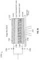
- FIGS. 16 and 18each disclose a schematic diagram of a light emitting device 316 and 332 for an LED circuit driver according to an embodiment of the invention.
- the device 316includes the device 300 as disclosed in FIG. 15 (with additional LEDs 306 added in series) mounted on an insulating substrate 318 such as, but not necessarily, ceramic or sapphire, and forming an LED package 320 that may be various sizes; materials and designs based of product specifications or on printed circuit board material. As shown in FIG.
- the device 316 , 332provides power connection leads 322 and 323 and may have a first or additional lens that may be made of a plastic, polymer or other material used for light dispersion and the lens may be coated or doped with a phosphor or nano-particle that would produce a change in the color or quality of light emitted from device 300 through the lens.
- LED package 320may include rectifier 302 to drive LEDs 306 .
- Rectifier 306may be mounted on insulating substrate 318 along with any LEDs.
- any diode or LEDmay be swapped for the other within the package so long as the package includes at least one LED to emit light when in operation.
- Any capacitors 312 , 314 or resistors 313 included in the light emitting devicesmay like wise be mounted on substrate 318 and included in LED package 320 .
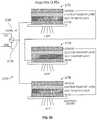
- rectifier 302may be discretely packaged separate from any discrete LED packages 324 where discrete LED package 324 includes one LED 306 or multiple LEDs connected in series or parallel.
- Rectifier 302may be packaged into rectifier package 326 for plug and use into a light system, or alternatively may be included as part of a driver used to drive the series LEDs.
- package 326may be provided with input power connections 328 and 329 which to connect the inputs of the rectifier to an AC power supply.
- package 326may also be provided with output power connections 330 and 331 which may connect to LED package inputs 334 and 335 .
- Any capacitors 312 , 314 or resistors 313 included in the light emitting devicesmay like wise be mounted on substrate 316 and included in rectifier package 326 .
- any number of LEDsmay be connected in series or parallel in a device to match a desired voltage and light output.
- a lighting devicethat is run off of a 120 V source and contains LEDs having a forward operating voltage of 3V each connected to a bridge rectifier having diodes also having a forward operating voltage of 3V each, approximately 38 LEDs may be placed in series to drop the required voltage.
- FIG. 19discloses an embodiment of an LED lighting device encapsulated in a housing.
- LED device 336may include a housing 338 encapsulating at least one bridge rectifier 340 , at least one LED circuit 342 connected across the output of the bridge rectifier.
- Device 334includes first power connection lead connected 344 to a first input of the rectifier 346 and a second power connection lead 348 connected to a second input of the rectifier 350 . At least a portion of each power connection is contained within the housing while at least a portion of each power connection extends beyond the housing to allow device 336 to connect to an AC power source.
- Rectifier 340 and LED circuit 342may be connected, assembled, and/or packaged within housing 336 using any of the methods described in conjunction with FIGS. 15-18 or any other means known in the art. It should be appreciated by those having ordinary skill in the art that the devices and packages described in FIGS. 2, 3, and 5-14 may likewise incorporate a housing to encapsulate any device and/or package therein.
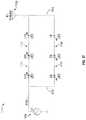
- FIG. 20discloses a schematic diagram of a lighting system 168 according to an embodiment of the invention.
- the device 168includes a plurality of devices 26 as described in FIG. 2 connected to a high frequency inverter AC drive Method 170 as described in FIG. 3 which in this example provides a relatively constant 12V AC source at a relatively constant frequency of 50 Khz to the devices 26 .
- Each or some of the devices 26may have integrated capacitors 172 of equal or different values enabling the devices 26 to operate at different drive currents 174 from a single source AC drive Method.
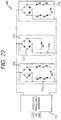
- FIG. 21discloses a schematic diagram of a lighting system 176 according to an embodiment of the invention.
- the lighting system 176includes a plurality of devices 178 , 180 and 182 each able to have operate at different currents and lumens output while connected directly to the transformer 184 output of a fixed high frequency AC drive Method 186 .
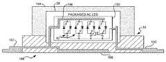
- FIG. 22discloses a schematic diagram of a lighting system 400 according to an embodiment of the invention.
- System 400includes a plurality of devices 316 , 332 as described in FIGS. 16 and 18 connected to a high frequency inverter AC drive Method 170 similar to that described in FIGS. 3 and 20 which provides a relatively constant 12V AC source at a relatively constant frequency of 50 Khz to the devices 316 , 332 .
- Each or some of the devices 316 , 332may have integrated capacitors 312 , 314 and resistors 313 of equal or different values enabling the devices 300 to operate at different drive currents from a single source AC drive Method.
- any voltage at substantially any frequencymay be provided by the driver by utilizing a proper transformer and/or inverter circuit.
- AC drive Method 186may be utilized may be used with a single or plurality of devices 214 as disclosed in FIG. 23 .
- each device 316 , 332may be connected directly to transformer 184 output to receive a substantially fixed frequency voltage.
- FIG. 24discloses an embodiment of the invention where AC drive Method 186 is provided to a rectifier and LED series strings are discretely packaged.
- rectifier 302may be discretely packaged in a rectifier package 326 , separate from both AC drive Method 186 (or alternatively AC drive Method 170 ) and discrete LED packages 324 , or alternatively may be included in AC drive Method 186 .
- FIG. 25discloses another schematic view diagram of a light emitting device 188 identical to the device 130 disclosed in FIG. 11 and integrated into a package 30 as described in FIG. 2 for an AC drive Method according to an embodiment of the invention.
- the device 188includes the device 130 as disclosed in FIG. 11 mounted on an insulating substrate 28 such as but not necessarily ceramic or sapphire and integrated into an LED package 30 that may be various LED package sizes; materials and designs based of product specifications or on printed circuit board material.
- the device 188provides power connection leads 190 and 192 and may have a first or additional lens 194 that may be made of a plastic, polymer or other material used for light dispersion and the lens may be coated or doped with a phosphor or nano-crystals that would produce a change in the color or quality of light emitted from the device 130 through the lens 194 .
- the device 130has a matrix of devices 10 .
- the power connection opposite the capacitors 16 within the device 130 and part of each device 10is connected to a power connection 196 that is connected to a solderable heat sinking material 198 and integrated into the package 30 .
- the power connection 196 connected to the heat sink 198may be of a heavier gauge within the device 130 or 188 than other conductors.
- the schematic view of the device 188provides a side view of the package 30 and an overhead view of the device 130 in this FIG. 25 .
- FIG. 26discloses another schematic view diagram of a light emitting device 198 similar to the device 188 described in FIG. 25 with a different light emitting device 200 identical to the device 136 disclosed in FIG. 12 and integrated into a package 30 as described in FIG. 2 for an AC drive Method according to an embodiment of the invention.
- the device 198includes a reflective device integrated into the package 30 for optimized light dispersion.
- the light emitting device 200may be facing down towards the reflector 202 and opposite direction of light output from the lens 194 if the reflector 202 is integrated into the package 30 properly for such a design.
- FIG. 27discloses another schematic view diagram of a light emitting device 500 similar to that shown in FIG. 24 according to an embodiment of the invention.
- the device 500includes the devices 316 , 332 similar to those disclosed in FIGS. 16 and 18 , mounted on an insulating substrate 318 such as but not necessarily ceramic or sapphire and integrated into an LED package 320 that may be various LED package sizes; materials and designs based of product specifications or on printed circuit board material.
- the device 500provides power connection leads 502 and 503 which connect to package power connect leads 322 and 323 and may have a first or additional lens 504 that may be made of a plastic, polymer or other material used for light dispersion and the lens may be coated or doped with a phosphor or nano-crystals that would produce a change in the color or quality of light emitted from the device through the lens 504 .
- Power connection 322may be connected to heat sink 506 and may be of a heavier gauge within the device than other conductors.
- FIG. 28discloses another schematic view diagram of a light emitting device 508 similar to that shown in FIG. 26 .
- Device 508is contemplated for use in embodiments where the rectifier is discretely packaged or included as part of AC drive Method 170 or 186 .
- power connection leads 510 and 511connect to the outputs of rectifier 302 (not shown) to provide power to LED packages 324 .
- FIG. 29shows a block diagram of an LED circuit driver 204 having a high frequency inverter 206 stage that provides a relatively constant voltage and relatively constant frequency output.
- the high frequency inverter 206 stagehas an internal dual half bridge driver with an internal or external voltage controlled oscillator that can be set to a voltage that fixes the frequency.
- a resistor or center tapped series resistor diode network within the high frequency inverter 206 stagefeeds back a voltage signal to the set terminal input of the oscillator.
- An AC regulator 208senses changes to the load at the output lines 210 and 212 of the inverter 206 and feeds back a voltage signal to the inverter 208 in response changes in the load which makes adjustments accordingly to maintain a relatively constant voltage output with the relatively constant frequency output.
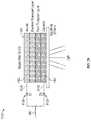
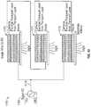
- FIG. 30shows a schematic diagram of an LED circuit driver 214 having a voltage source stage 216 , a fixed/adjustable frequency stage 218 , an AC voltage regulator and measurement stage 220 , an AC level response control stage 222 , an AC regulator output control stage 224 and a driver output stage 226 .
- FIG. 31shows a schematic diagram of the voltage source stage 216 described in FIG. 20 .
- the voltage source stage 216provides universal AC mains inputs 228 that drive a diode bridge 230 used to deliver DC to the LED circuit driver system 214 . Direct DC could eliminate the need for the universal AC input 228 .
- Power factor correction means 232may be integrated into the LED circuit driver 216 as part of the circuit.
- the voltage source stage 216includes a low voltage source circuit 234 that may include more than one voltage and polarity.
- FIG. 32shows a schematic diagram of the fixed/adjustable frequency stage 218 as described in FIG. 20 .
- the fixed/adjustable frequency stage 218includes a bridge driver 236 that may include an integrated or external voltage controlled oscillator 238 .
- the oscillator 238has a set input pin 240 that sets the frequency of the oscillator to a fixed frequency through the use of a resistor or adjustable resistor 242 to ground.
- the adjustable resistor 242allows for adjusting the fixed frequency to a different desired value through manual or digital control but keeps the frequency relatively constant based on the voltage at the set terminal 240 .
- FIG. 33is a schematic diagram of the AC voltage regulator with voltage measurement stage 220 as described in FIG. 20 .
- the AC voltage regulator with voltage measurement circuit 220monitors the voltage at the driver output 226 as shown in FIG. 20 and sends a voltage level signal to the AC level response control stage 222 as shown in FIG. 20 .
- FIG. 34is a schematic diagram of the AC level response control 228 stage.
- the AC level response control stage 228receives a voltage level signal from the AC voltage regulator with voltage measurement circuit 220 as shown in FIG. 23 and drives the AC regulator output control stage 224 as shown in FIG. 20 .
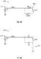
- FIG. 35is a schematic diagram of the AC regulator output control stage 230 .
- the AC regulator output control stage 230varies the resistance between the junction of the drive transistors 232 and the transformer input pin 234 of the driver output 226 as shown in FIG. 26 .
- the AC regulator output control stage 230is a circuit or component such as but not necessarily a transistor, a voltage dependent resistor or a current dependent resistor circuit having a means of varying its resistance in response to the voltage or current delivered to it.
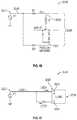
- FIG. 36is a schematic diagram of the driver output stage 226 .
- the driver output stage 226includes drive transistors 232 and the transformer 236 that delivers an AC voltage output 238 to LED circuits at a relatively constant voltage and frequency.
- FIGS. 37 and 38discloses a circuit 1104 to illustrate another aspect of the invention. Accordingly, an alternating electric field is provided to a first transmission conductor by a signal generator 1102 and a second transmission conductor is provided by an antenna 1108 (see FIG. 37 ) or wire 1124 (see FIG. 38 ) that is connected to a relatively less positive side 1114 - 1122 within the directional circuit 1110 . A difference in DC potential between a relatively more positive side 1112 within the directional circuit, and relatively less positive side 1114 - 1122 is provided.
- Another aspect of the inventionis sensing proximity with impedance changes within the directional circuits described herein (as it could be with any embodiment disclosed herein) by approaching any of the directional circuits or transmission conductors (also any of which are described herein), for example approaching 1108 (shown in FIG. 37 ) and/or 1124 (as shown in FIG. 38 ) with a conductive substance such as a person or metallic material thereby changing the circulation of current flow within the directional circuit by changes in impedance through the capacitance of the conductive substance.
- FIGS. 39, and 40-41disclose another embodiment of the invention having a directional organic light emitting diode (“OLEO”) circuit 1154 that includes a first diode D 1 1156 , a second diode D 2 1158 , and an OLED 1157 .
- the first diode D 1 1156has an anode and the second diode D 2 1158 has a cathode, which are commonly connected to a input transmission conductor 1160 .
- the cathode of diode D 1 1156is connected to the relatively more positive side 1162 anode of an OLED 1157 while the anode of diode D 2 11 is connected to the relatively less positive side cathode 1164 of the OLED 1157 to form the loop circuit 1154 among the diodes D 1 , D 2 and the OLED 1157 .
- the directional OLEO circuit 154is a loop circuit which includes one or more circuit elements (e.g. diodes or OLEDs 1156 , 1157 and 1158 ) causing the loop circuit to be asymmetric to current flow.
- Circuit element 1157is an OLED.
- the directional OLEO circuit 1154does not have a continuous conductive path to earth ground, or battery ground.
- the directional OLEO circuit 1154develops a DC potential in response to a alternating electric field imposed on input 1160 .
- the directional OLEO circuit 1154is self referencing between a relatively high potential output and a relatively lower potential output.
- the directional OLEO circuit 1154has a resistance, inductance and capacitance that is responsive to the voltage and frequency of the alternating electric field.
- the directional OLEO circuit 1154has transmission conductors 1166 , 1168 connected to the directional OLEO circuit 1154 .
- FIG. 40discloses a circuit 1182 with the same embodiment of the invention shown in FIG. 39 (see FIG. 39 ) encasing the directional OLEO circuit 1154 within a package 1163 .
- FIG. 41discloses a circuit 1184 with the same embodiment of the invention shown in FIG. 39 (see FIG. 39 ) with a second transmission conductor 1185 providing an input within the directional circuit 1184 at a point other than the input of the first transmission conductor input of 1160 .
- the transmission conductors 1160 and 1185can act as an antenna and cause the directional OLEO circuit 1184 to react to the proximity of conductive substances near the transmission conductors 1160 and 1185 .
- the circuits disclosed in FIGS. 39-41 and 43 belowmay be connected to ground through capacitance at a point within the directional circuit such as transmission conductor 1185 (e.g. FIG. 41 ). This ground connection seems to provide increased circulation current, as it is noted that the OLEDs get brighter for a given alternating electromagnetic source.
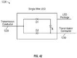
- FIG. 42discloses a circuit 1226 identical to circuit 1210 but that the circuit has a first transmission conductor 1228 and a second transmission conductor 1230 .
- Each transmission conductor 1228 , 230can be driven with an alternating electric field and can cause the circuit 1226 to react to the proximity of a conductive substance that approaches the transmission conductors 1228 and 1230 with only one or both conductors being driven.
- FIG. 43discloses another embodiment of the invention having a directional organic light emitting diode (“OLEO”) circuit 1170 that includes a first OLEO 1172 , a second OLEO 1174 , and a third OLEO 1176 .
- the first OLEO 1172has an anode and the third OLEO 1176 has a cathode, which are commonly connected to an input transmission conductor 1178 having AC signal source from a signal generator 1180 .
- the cathode of the first OLEO 1172is connected to the anode of the second OLEO 1174 while the cathode of the second OLEO 1174 is connected to the anode of the third OLEO 1176 to form the loop circuit 1170 among the OLEDs 1 , 2 and 3 ( 1172 - 1176 ).
- the directional OLEO circuit 1170can be designed with more than 3 OLEDs.
- FIG. 44discloses a preferred circuit 2010 according to the invention.
- the circuit 2010includes a first source for providing an alternating electric field.
- the sourcemay be 120V or 240V line power, RF energy or the output of a standard AC signal generator such as generator 2012 of FIG. 44 .
- This generator 2012may produce its signal with reference to ground as indicated in FIG. 44 .
- Circuit 2010also discloses a directional circuit 2014 connected to the generator 2012 by a transmission conductor 2016 .
- the conductor 2016may be any form of conventional conductive path whether twisted wire bundles, single wires, etc. The point is that the transmission conductor 2016 provides a single transmission path to the directional circuit 2014 .
- Important to the inventionis the fact that there is no conductive return path provided back from the directional circuit 2016 to the generator 2012 .
- the directional circuit 2014is a loop circuit which includes one or more circuit elements causing the loop circuit to be asymmetric to current flow. Again it is important that the directional circuit 2014 has no continuous conductive path to earth ground, or a battery ground. As such, and as disclosed in FIG. 44 the directional circuit 2014 develops a DC potential across a load, such as resistor R 1 in response to the alternating electric field. This DC potential is not referenced to ground but merely to the potential differences created by the circulation of current (see FIG. 45 ) in the loop across the load (resistor R 1 of FIG. 44 ). Accordingly, the DC potential is self referencing. As far as the resistor R 1 is concerned, circuit 2010 presents it with a relatively higher DC potential output at 2020 and a relatively lower potential output at 2022 .
- FIG. 45discloses circuit 2010 with the load represented as a generic load 2024 (rather than resistor R 1 ) to show the circulation path of current flow (indicated by the arrows) in any generic load circuit utilizing the DC potential of circuit 2010 .
- FIGS. 44 and 45disclose that the loads connected to the directional circuit 2014 do not have a continuous conductive path to earth ground or a battery ground. They also disclose that the directional circuit 2014 has circuit elements causing the directional circuit to be asymmetric to current flow. In the preferred embodiment disclosed, these circuit elements are diodes D 1 and D 2 . However, it is contemplated that numerous other circuit elements could provide the same functionality, in particular, semiconductors with “pn” junctions; electrets, plasma, organic; or combinations thereof.
- the circuit 2010is preferably used for delivering power and sensing proximity.
- the circuit 2010is also preferably useful in TTL logic applications as disclosed in FIG. 46 showing a standard TTL logic output circuit 2026 powered by circuit 2010 . In that application, the DC voltages necessary range from 0V to +/ ⁇ 5V.
- FIGS. 44-46each disclose that directional circuit 2014 includes first and second diodes D 1 and D 2 , with D 1 having an anode and diode D 2 having a cathode which are commonly connected to the transmission conductor 2016 .
- the cathode of the first diode D 1is connected to the relatively more positive side of the load 2020 while the anode of the second diode is connected to the relatively less positive side load 2022 to form the directional loop circuit among the diodes and the load.
- FIG. 47discloses a circuit 2024 according to the invention having a standard AC signal generator 2026 and a directional circuit 2028 includes first and second light emitting diodes (LEDs), the first LED 1 has an anode and the second LED 2 has a cathode, which are commonly connected to the conductor 2030 from the generator 2026 .
- the cathode of LED 1is connected to the relatively more positive voltage side 2032 of the load 2036 while the anode of LED 2 is connected to the relatively less positive side 2034 of the load 2036 to form the loop circuit 2028 among the LEDs 1 and 2 .
- the loadis configured to optimize the lumen produced by the directional circuit, for example the LEDs 1 , 2 used to deliver power to the load 2036 which can be a third LED as shown in FIG. 48 .
- FIG. 48discloses a circuit 2038 according to the invention.
- a generator 2040produces an alternating electric field on transmission conductor 2040 .
- the conductor 2041is connected to a directional circuit 2042 having circuit elements causing an asymmetrical response to the alternating field and current flow.
- circuit 2042includes three LEDs 1 , 2 , 3 , configured to provide circulation according to the direction of the arrows (see FIG. 48 ).
- all three LEDs 1 - 3provide light as an output that can be considered as a load. This shows that relative nature of the positioning of elements in the various directional circuits disclosed herein according to the invention. If light is desired, then each of the diodes may be considered both loads and circuit elements which cause asymmetrical current flow.
- FIG. 49discloses the same circuit 2038 with only the substitution of LEDs 1 and 3 by diodes D 1 and D 2 .
- optimization of the light emitted by LED 2is of paramount concern, whereas the diodes 1 , 2 provide directionality and a DC offset to the AC signal source as will be disclosed in more detail below.
- the directional circuits, including directional circuit 2014 , disclosed herein throughout this inventionmay be connected to ground through capacitance 2039 at a point within the directional circuit other than the AC signal input point 40 as shown in FIG. 49 .
- This ground connectionseems to provide increased circulation current, as it is noted that the LEDs get brighter for a given alternating electromagnetic source.
- the capacitor 2039may alternatively be placed on the other side of the AC line 2041 . The capacitor is used to drop the voltage from the AC source.
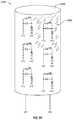
- FIG. 50discloses a circuit 2042 having an AC signal generator 2044 inducing an alternating electric field onto transmission conductor 2046 which is connected to a first directional circuit 2048 having LEDs 1 - 3 .
- LED 2 acting as a load to circuit 2048provides the relatively high DC potential at point 2050 and a relatively lower DC potential at point 2052 to another directional circuit 2054 comprised of LEDs 4 - 6 . This is repeated for another directional circuit 2056 and LEDs 7 - 9 .
- the circuit components LEDs 1 - 9provide both directionality and useful work as a load in the form of producing light.
- the circuit 2042discloses the multiplexing possibilities of the directional circuits 2048 , 2052 , 2056 .
- the circuit 2042discloses a parallel LED directional circuit.
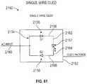
- FIG. 51discloses a circuit 2058 to illustrate another aspect of the invention, in particular the transmission of information or data as one may use the terms. Accordingly, the alternating electric field is provided (as it could be with any embodiment disclosed herein) by either an antenna 2060 or a signal generator 2061 . The alternating signal source is imposed on transmission conductor 2062 .
- a directional circuit 2064is comprised of a load 2066 and two diodes D 1 and D 2 .
- the circuit 2058discloses the directional DC current flow as well as an AC plus DC current flow and potential indicated by “AC+DC” in FIG. 51 . This DC plus AC component is important to the transmission of information or data signals from the generators 2060 , 2061 .
- FIG. 52discloses a circuit 2068 having a signal generator 2070 , a transmission conductor 2072 , and a directional circuit 2074 .
- the directional circuithas asymmetrical diode elements D 1 and D 2 and a load R 1 .
- the directional circuit 2074is constructed to permit a DC voltage level to accrue on the transmission conductor 2072 along with the AC signal to provide an offset to the signal. This offset is preferential to the signal as the signal is ungrounded. It is believed that this may prevent noise in the system to be added to the line 2072 as a second alternating field but with reference to ground. Accordingly the noise adds to the DC level but not to the signal level in the same proportions.
- an output 2076is provided which will transmit the AC signals from transmission line 2072 to an information or data signal receiver 2078 which will detect the signal riding the DC level.
- the DC levelcan easily be distinguished and handled by such a receiver as is conventional.
- the signal receiver 2078may be of any conventional type of TTL logic device, modem, or telecommunications receiver and is believed to operate best with the preferred systems of the invention when it is not connected to earth ground or a battery ground, or a current sink or charge collector (as is the case for the working loads disclosed through out this disclosure).
- FIG. 53discloses another information or data communication circuit 2080 .
- the circuit 2080includes a signal generator 2082 , a transmission conductor 2084 , a directional circuit 2086 , a data receiver 2088 , and a ground switch 2090 .
- the directional circuit 2086provides both the DC power for the receiver 2088 , and a data signal through output 2092 connected between the receiver input and the common connection between the conductor 2084 and directional circuit input to anode of diode D 1 and cathode D 2 .
- the receiveris powered on the DC potential difference between D 1 the relatively more positive side 2094 and D 2 the relatively less positive side 2096 of the directional circuit.
- resistor R 1is provided according to another aspect of the invention to regulate or select as desired the level of DC offset the AC data signal will have at line 2092 .
- the ground switch 2090is provided to provide a non-continuous connection to a circuit, such as the ground circuit disclosed in FIG. 53 , to dissipate excessive accumulations of charge or voltage potentials in the circuit 2080 . It is contemplated that the switch 2090 be actuated based upon a timing (such as a pre-selected clock pulse) criteria, or by a sensor (not shown) of an undesirable DC level developing in the circuit 2080 . Once engaged, the circuit 2090 would dissipate the excess energy to a ground, ground, plane, capacitor, battery ground, or the like.
- FIG. 54discloses a circuit 2092 wherein directional circuits 2094 - 2100 are connected through a common bus conductor 2102 to provide DC power and signals from generator 2104 as described previously herein.
- FIGS. 55 and 56disclose a circuit 2104 to illustrate another aspect of the invention. Accordingly, an alternating electric field is provided to a first transmission conductor by a signal generator 2102 and a second transmission conductor is provided by an antenna 2108 (see FIG. 55 ) or wire 2124 (see FIG. 56 ) that is connected to a relatively less positive side 2114 - 2122 within the directional circuit 2110 . A difference in DC potential between a relatively more positive side 2112 within the directional circuit, and relatively less positive side 2114 - 2122 is provided.
- Another aspect of the inventionis sensing proximity with impedance changes within the directional circuits described herein (as it could be with any embodiment disclosed herein) by approaching any of the directional circuits or transmission conductors (also any of which are described herein), for example approaching 2108 (shown in FIG. 55 ) and/or 2124 (as shown in FIG. 56 ) with a conductive substance such as a person or metallic material thereby changing the circulation of current flow within the directional circuit by changes in impedance through the capacitance of the conductive substance.
- FIG. 57discloses a circuit 2126 to illustrate another aspect of the invention. Accordingly, an alternating electric field is provided to a transmission conductor 2132 by a signal generator 2128 that provides a first voltage level output equal to that provided by the signal generator 2128 .
- a lump inductance 2130is provided in series of the transmission conductor 2132 between the signal generator 2128 and directional circuit 2134 .
- the lump inductance 2130provides an increased voltage level from the relatively lower voltage on the transmission conductor 2132 at the point 2136 between the signal generator 2128 and lump inductance 2136 and a relatively higher voltage level on the transmission conductor 2132 at the point 2138 between the lump inductance 2130 and the directional circuit 2134 thereby providing an increase in current flow within the directional circuit 2134 or electromagnetic field energy radiating from the circuit 2126 .
- the amount of current flow within the directional circuits described herein and electromagnetic field energy external of the directional circuits described hereinis dependent on the frequency of an AC signal provided to the transmission conductor 2132 (or any of which are described herein).
- the circuits disclosed in FIGS. 44-57may be connected to ground through capacitance. This ground connection seems to provide increased circulation current, as it is noted that the LEDs get brighter for a given alternating electromagnetic source.
- FIG. 58discloses a circuit 2140 according to the invention having a standard AC signal generator 2142 and a directional circuit 2144 that includes first and second diodes D 1 , D 2 , the first diode D 1 has an anode and the second diode D 2 has a cathode, which are commonly connected to the transmission conductor 2146 from the generator 2142 .
- the cathode of diode D 1is connected to the relatively more positive side 2148 of an organic light emitting diode (OLED) 2152 while the anode of diode D 2 is connected to the relatively less positive side 2150 of the OLED 2152 to form the loop circuit 2144 among the diodes D 1 , D 2 and the OLED 2152 .
- OLEDorganic light emitting diode
- FIGS. 59, and 61-62disclose another embodiment of the invention having a directional organic light emitting diode (“OLED”) circuit 154 that includes a first diode D 1 2156 , a second diode D 2 2158 , and an OLED 2157 .
- the first diode D 1 2156has an anode and the second diode D 2 2158 has a cathode, which are commonly connected to a input transmission conductor 2160 .
- the cathode of diode D 1 2156is connected to the relatively less positive side cathode 2164 of the OLED 2157 to form the loop circuit 2154 among the diodes D 1 , D 2 and the OLED 2157 .
- the directional OLED circuit 2154is a loop circuit which includes oen or more circuit elements (e.g. diodes or OLEDs 2156 , 2157 and 2158 ) causing the loop circuit to be asymmetric to current flow.
- Circuit element 2157is an OLED.
- the directional OLED circuit 2154does not have a continuous conductive path to earth ground, or battery ground.
- the directional OLED circuit 2154develops a DC potential in response to a alternating electric field imposed on input 2160 .
- the directional OLED circuit 2154is self referencing between a relatively high potential output and a relatively lower potential output.
- the directional OLED circuit 2154has a resistance, inductance nad capacitance that is responsive to the voltage and frequency of the alternating electric field.
- the directional OLED circuit 2154has transmission conductors 2166 , 2168 connected to the directional OLED circuit 2154 .
- FIG. 60discloses another embodiment of the invention having a directional organic light emitting diode (“OLED”) circuit 2170 that includes a first OLED 2172 , a second OLED 2174 , and a third OLED 2176 .
- the first OLED 2172has an anode and the third OLED 2176 has a cathode, which are commonly connected to an input transmission conductor 2178 having AC signal source from a signal generator 2180 .
- the cathode of the first OLED 2172is connected to the anode of the second OLED 2174 while the cathode of the second OLED 2174 is connected to the anode of the third OLED 2176 to form the loop circuit 2170 among the OLEDs 1 , 2 and 3 ( 2172 - 2176 ).
- the directional OLED circuit 2170can be designed with more than 3 OLEDs.
- FIG. 61discloses a circuit 2182 with the same embodiment of the invention shown in FIG. 59 (see FIG. 59 ) encasing the directional OLED circuit 2154 within a package 2163 .
- FIG. 62discloses a circuit 2184 with the same embodiment of the invention shown in FIG. 59 (see FIG. 59 ) with a second transmission conductor 2185 providing an input within the directional circuit 2184 at a point other than the input of the first transmission conductor input of 2160 .
- the transmission conductors 2160 and 2185can act as an antenna and cause the directional OLED circuit 2184 to react to the proximity of conductive substances near the transmission conductors 2160 and 2185 .
- the circuits disclosed in FIGS. 59-62may be connected to ground through capacitance at a point within the directional circuit such as transmission conductor 2185 (e.g. FIG. 62 ). This ground connection seems to provide increased circulation current, as it is noted that the OLEDs get brighter for a given alternating electromagnetic source.
- FIG. 63shows a device 2482 comprising individual light emitting diode circuits 2484 on a flexible printed circuit board having a mirror like reflective material or coating 2488 designed into or on the flexible printed circuit board in an area at least near the light emitting diodes for providing more efficient light output from the circuit board areas surrounding the light emitting diodes by having the flexible printed circuit board reflect light rather than absorb it.
- Power connection points 2490 and 2492are provided to the board.
- FIG. 64shows a device 2494 comprising a device 2496 identical to the device shown in FIG. 58 adhered to a device 2498 having a cylindrical shape for providing improved uniformity and increased angle of light output from device 2496 .
Landscapes
- Circuit Arrangement For Electric Light Sources In General (AREA)
- Led Devices (AREA)
Abstract
Description
Claims (23)
Priority Applications (13)
| Application Number | Priority Date | Filing Date | Title |
|---|---|---|---|
| US16/148,945US10492251B2 (en) | 2004-02-25 | 2018-10-01 | AC light emitting diode and AC LED drive methods and apparatus |
| US16/407,076US10492252B2 (en) | 2004-02-25 | 2019-05-08 | AC light emitting diode and AC LED drive methods and apparatus |
| US16/443,759US10575376B2 (en) | 2004-02-25 | 2019-06-17 | AC light emitting diode and AC LED drive methods and apparatus |
| US16/449,273US10750583B2 (en) | 2004-02-25 | 2019-06-21 | AC light emitting diode and AC LED drive methods and apparatus |
| US16/523,388US10506674B2 (en) | 2004-02-25 | 2019-07-26 | AC light emitting diode and AC LED drive methods and apparatus |
| US16/523,542US10499466B1 (en) | 2004-02-25 | 2019-07-26 | AC light emitting diode and AC LED drive methods and apparatus |
| US16/693,081US10687400B2 (en) | 2004-02-25 | 2019-11-22 | AC light emitting diode and AC LED drive methods and apparatus |
| US16/740,225US11019697B2 (en) | 2004-02-25 | 2020-01-10 | AC light emitting diode and AC led drive methods and apparatus |
| US16/866,119US10966298B2 (en) | 2004-02-25 | 2020-05-04 | AC light emitting diode and AC LED drive methods and apparatus |
| US17/216,032US11638336B2 (en) | 2004-02-25 | 2021-03-29 | AC light emitting diode and AC LED drive methods and apparatus |
| US17/306,450US20210259078A1 (en) | 2004-02-25 | 2021-05-03 | Ac light emitting diode and ac led drive methods and apparatus |
| US18/138,577US20230262854A1 (en) | 2012-11-13 | 2023-04-24 | Ac light emitting diode and ac led drive methods and apparatus |
| US18/604,068US12279345B2 (en) | 2009-12-28 | 2024-03-13 | Light emitting diode and LED drive apparatus |
Applications Claiming Priority (19)
| Application Number | Priority Date | Filing Date | Title |
|---|---|---|---|
| US54765304P | 2004-02-25 | 2004-02-25 | |
| US55986704P | 2004-04-06 | 2004-04-06 | |
| US11/066,414US7489086B2 (en) | 2004-02-25 | 2005-02-25 | AC light emitting diode and AC LED drive methods and apparatus |
| US99777107P | 2007-10-06 | 2007-10-06 | |
| US12/287,267US8179055B2 (en) | 2007-10-06 | 2008-10-06 | LED circuits and assemblies |
| US12/364,890US8148905B2 (en) | 2004-02-25 | 2009-02-03 | AC light emitting diode and AC LED drive methods and apparatus |
| US21514409P | 2009-05-01 | 2009-05-01 | |
| US21721509P | 2009-05-28 | 2009-05-28 | |
| US28492709P | 2009-12-28 | 2009-12-28 | |
| US33506909P | 2009-12-31 | 2009-12-31 | |
| PCT/US2010/001269WO2010126601A1 (en) | 2009-05-01 | 2010-04-30 | Led circuits and assemblies |
| US33396310P | 2010-05-12 | 2010-05-12 | |
| PCT/US2010/001597WO2010138211A1 (en) | 2009-05-28 | 2010-05-28 | Multi-voltage and multi-brightness led lighting devices and methods of using same |
| PCT/US2010/062235WO2011082168A1 (en) | 2009-12-28 | 2010-12-28 | High frequency multi-voltage and multi-brightness led lighting devices |
| PCT/US2011/036359WO2011143510A1 (en) | 2010-05-12 | 2011-05-12 | Led lighting system |
| US201213697646A | 2012-11-13 | 2012-11-13 | |
| US14/948,635US9615420B2 (en) | 2004-02-25 | 2015-11-23 | LED lighting system |
| US15/334,029US10091842B2 (en) | 2004-02-25 | 2016-10-25 | AC light emitting diode and AC LED drive methods and apparatus |
| US16/148,945US10492251B2 (en) | 2004-02-25 | 2018-10-01 | AC light emitting diode and AC LED drive methods and apparatus |
Related Parent Applications (1)
| Application Number | Title | Priority Date | Filing Date |
|---|---|---|---|
| US15/334,029ContinuationUS10091842B2 (en) | 2004-02-25 | 2016-10-25 | AC light emitting diode and AC LED drive methods and apparatus |
Related Child Applications (1)
| Application Number | Title | Priority Date | Filing Date |
|---|---|---|---|
| US16/407,076ContinuationUS10492252B2 (en) | 2004-02-25 | 2019-05-08 | AC light emitting diode and AC LED drive methods and apparatus |
Publications (2)
| Publication Number | Publication Date |
|---|---|
| US20190045593A1 US20190045593A1 (en) | 2019-02-07 |
| US10492251B2true US10492251B2 (en) | 2019-11-26 |
Family
ID=59315058
Family Applications (3)
| Application Number | Title | Priority Date | Filing Date |
|---|---|---|---|
| US15/334,029Expired - LifetimeUS10091842B2 (en) | 2004-02-25 | 2016-10-25 | AC light emitting diode and AC LED drive methods and apparatus |
| US16/148,945Expired - LifetimeUS10492251B2 (en) | 2004-02-25 | 2018-10-01 | AC light emitting diode and AC LED drive methods and apparatus |
| US16/407,076Expired - LifetimeUS10492252B2 (en) | 2004-02-25 | 2019-05-08 | AC light emitting diode and AC LED drive methods and apparatus |
Family Applications Before (1)
| Application Number | Title | Priority Date | Filing Date |
|---|---|---|---|
| US15/334,029Expired - LifetimeUS10091842B2 (en) | 2004-02-25 | 2016-10-25 | AC light emitting diode and AC LED drive methods and apparatus |
Family Applications After (1)
| Application Number | Title | Priority Date | Filing Date |
|---|---|---|---|
| US16/407,076Expired - LifetimeUS10492252B2 (en) | 2004-02-25 | 2019-05-08 | AC light emitting diode and AC LED drive methods and apparatus |
Country Status (1)
| Country | Link |
|---|---|
| US (3) | US10091842B2 (en) |
Cited By (9)
| Publication number | Priority date | Publication date | Assignee | Title |
|---|---|---|---|---|
| US11284491B2 (en) | 2011-12-02 | 2022-03-22 | Lynk Labs, Inc. | Color temperature controlled and low THD LED lighting devices and systems and methods of driving the same |
| US11297705B2 (en) | 2007-10-06 | 2022-04-05 | Lynk Labs, Inc. | Multi-voltage and multi-brightness LED lighting devices and methods of using same |
| US11317495B2 (en) | 2007-10-06 | 2022-04-26 | Lynk Labs, Inc. | LED circuits and assemblies |
| US11528792B2 (en) | 2004-02-25 | 2022-12-13 | Lynk Labs, Inc. | High frequency multi-voltage and multi-brightness LED lighting devices |
| US11566759B2 (en) | 2017-08-31 | 2023-01-31 | Lynk Labs, Inc. | LED lighting system and installation methods |
| US11638336B2 (en) | 2004-02-25 | 2023-04-25 | Lynk Labs, Inc. | AC light emitting diode and AC LED drive methods and apparatus |
| US11678420B2 (en) | 2004-02-25 | 2023-06-13 | Lynk Labs, Inc. | LED lighting system |
| US11953167B2 (en) | 2011-08-18 | 2024-04-09 | Lynk Labs, Inc. | Devices and systems having AC LED circuits and methods of driving the same |
| US12279345B2 (en) | 2009-12-28 | 2025-04-15 | Lynk Labs, Inc. | Light emitting diode and LED drive apparatus |
Families Citing this family (9)
| Publication number | Priority date | Publication date | Assignee | Title |
|---|---|---|---|---|
| US10154551B2 (en) | 2004-02-25 | 2018-12-11 | Lynk Labs, Inc. | AC light emitting diode and AC LED drive methods and apparatus |
| US10506674B2 (en) | 2004-02-25 | 2019-12-10 | Lynk Labs, Inc. | AC light emitting diode and AC LED drive methods and apparatus |
| US10091842B2 (en) | 2004-02-25 | 2018-10-02 | Lynk Labs, Inc. | AC light emitting diode and AC LED drive methods and apparatus |
| US8957601B2 (en) | 2008-09-18 | 2015-02-17 | Lumastream Canada Ulc | Configurable LED driver/dimmer for solid state lighting applications |
| US9468062B2 (en)* | 2013-01-02 | 2016-10-11 | Austin Ip Partners | Light emitting diode light structures |
| CN108375057B (en)* | 2018-01-22 | 2024-07-05 | 刘华旺 | Multi-device multi-unit loop line connection structure capable of being flexibly increased and decreased |
| US11876042B2 (en)* | 2020-08-03 | 2024-01-16 | Feit Electric Company, Inc. | Omnidirectional flexible light emitting device |
| US11802682B1 (en)* | 2022-08-29 | 2023-10-31 | Wangs Alliance Corporation | Modular articulating lighting |
| US12292169B1 (en) | 2024-07-10 | 2025-05-06 | Wangs Alliance Corporation | Shadowless connector |
Citations (134)
| Publication number | Priority date | Publication date | Assignee | Title |
|---|---|---|---|---|
| US3869641A (en) | 1972-06-21 | 1975-03-04 | Monsanto Co | AC Responsive led pilot light circuitry |
| US4218627A (en) | 1978-09-01 | 1980-08-19 | Polaroid Corporation | Electrical mean square voltage sensor |
| US4271408A (en) | 1978-10-17 | 1981-06-02 | Stanley Electric Co., Ltd. | Colored-light emitting display |
| US4298869A (en) | 1978-06-29 | 1981-11-03 | Zaidan Hojin Handotai Kenkyu Shinkokai | Light-emitting diode display |
| US4380721A (en) | 1980-12-29 | 1983-04-19 | Bullock John W | Proximity switch |
| US4506318A (en) | 1983-04-22 | 1985-03-19 | Nilssen Ole K | Inverter with controllable RMS output voltage magnitude |
| US4535203A (en) | 1982-12-08 | 1985-08-13 | Siliconix Limited | Bridge rectifier circuit |
| US4751398A (en) | 1986-03-18 | 1988-06-14 | The Bodine Company | Lighting system for normal and emergency operation of high intensity discharge lamps |
| US5180952A (en) | 1983-04-22 | 1993-01-19 | Nilssen Ole K | Electronic track lighting system |
| US5309062A (en) | 1992-05-20 | 1994-05-03 | Progressive Technology In Lighting, Inc. | Three-way compact fluorescent lamp system utilizing an electronic ballast having a variable frequency oscillator |
| US5442258A (en) | 1994-05-04 | 1995-08-15 | Hakuyo Denkyu Kabushiki Kaisha | LED lamp device |
| JPH08137429A (en) | 1994-11-14 | 1996-05-31 | Seibu Electric & Mach Co Ltd | Display device |
| US5559681A (en) | 1994-05-13 | 1996-09-24 | Cnc Automation, Inc. | Flexible, self-adhesive, modular lighting system |
| US5575459A (en) | 1995-04-27 | 1996-11-19 | Uniglo Canada Inc. | Light emitting diode lamp |
| US5640061A (en) | 1993-11-05 | 1997-06-17 | Vari-Lite, Inc. | Modular lamp power supply system |
| US5675485A (en) | 1994-12-22 | 1997-10-07 | Samsung Electronics Co., Ltd. | Switching mode power supply controller |
| US5699218A (en) | 1996-01-02 | 1997-12-16 | Kadah; Andrew S. | Solid state/electromechanical hybrid relay |
| US5739639A (en) | 1996-07-03 | 1998-04-14 | Nsi Enterprises, Inc. | Method and apparatus for operating LED array and charging battery for emergency LED operation including DC boost circuit allowing series connection of LED array and battery |
| US5790013A (en) | 1995-10-04 | 1998-08-04 | Hauck; Lane T. | Electronic novelty device and method of using same |
| US5821699A (en) | 1994-09-30 | 1998-10-13 | Pacific Scientific | Ballast circuit for fluorescent lamps |
| JPH1116683A (en) | 1997-06-23 | 1999-01-22 | Masanori Minato | Light emitting display device |
| WO1999020085A1 (en) | 1997-10-10 | 1999-04-22 | Se Kang Electric Co., Ltd. | Electric lamp circuit and structure using light emitting diodes |
| JPH11330561A (en) | 1998-05-14 | 1999-11-30 | Oki Electric Ind Co Ltd | Led luminaire |
| US6040663A (en) | 1997-08-01 | 2000-03-21 | U.S. Philips Corporation | Circuit arrangement |
| US6107744A (en) | 1995-11-29 | 2000-08-22 | Bavaro; Joseph P. | Back-up electrical systems |
| US6113248A (en) | 1997-10-20 | 2000-09-05 | The Standard Products Company | Automated system for manufacturing an LED light strip having an integrally formed connector |
| US6157551A (en) | 1998-11-09 | 2000-12-05 | Lightech Electronics Industries Ltd. | Electronic transformer for lighting |
| US6183104B1 (en) | 1998-02-18 | 2001-02-06 | Dennis Ferrara | Decorative lighting system |
| US20020030455A1 (en) | 1999-12-23 | 2002-03-14 | Gelcore, Llc | Non-linear light-emitting load current control |
| US20020047646A1 (en)* | 1997-08-26 | 2002-04-25 | Ihor Lys | Lighting entertainment system |
| US6380693B1 (en) | 1999-08-11 | 2002-04-30 | Patent-Treuhand-Gesellschaft Fuer Elektrische Gluehlampen Mbh | Apparatus for operating at least one light-emitting diode |
| US20020060526A1 (en) | 2000-02-11 | 2002-05-23 | Jos Timmermans | Light tube and power supply circuit |
| EP1215944A1 (en) | 2000-12-14 | 2002-06-19 | General Electric Company | Light emitting diode power supply |
| US6412971B1 (en) | 1998-01-02 | 2002-07-02 | General Electric Company | Light source including an array of light emitting semiconductor devices and control method |
| US6430064B1 (en) | 2001-06-29 | 2002-08-06 | Aichi Electric Co. Ltd. | Non-contact power supply device |
| US20020113246A1 (en) | 2001-01-25 | 2002-08-22 | Hideo Nagai | Light-emitting unit, light-emitting unit assembly, and lighting apparatus produced using a plurality of light-emitting units |
| US20020114155A1 (en) | 2000-11-24 | 2002-08-22 | Masayuki Katogi | Illumination system and illumination unit |
| US20030001657A1 (en) | 2001-05-18 | 2003-01-02 | Worley Eugene Robert | LED lamp package for packaging an LED driver with an LED |
| US20030043611A1 (en) | 2000-03-17 | 2003-03-06 | Tridonicatco Gmbh & Co. Kg | Drive for light-emitting diodes |
| US20030057886A1 (en) | 1997-08-26 | 2003-03-27 | Lys Ihor A. | Methods and apparatus for controlling devices in a networked lighting system |
| US6541919B1 (en) | 2000-02-14 | 2003-04-01 | Sarnoff Corporation | Electrical interconnection of light-emitting fibers, and method therefor |
| JP2003132708A (en) | 2001-10-25 | 2003-05-09 | Tanabe Take Shoten:Kk | Led illumination device |
| US6577072B2 (en) | 1999-12-14 | 2003-06-10 | Takion Co., Ltd. | Power supply and LED lamp device |
| US6580228B1 (en) | 2000-08-22 | 2003-06-17 | Light Sciences Corporation | Flexible substrate mounted solid-state light sources for use in line current lamp sockets |
| US20030122502A1 (en) | 2001-12-28 | 2003-07-03 | Bernd Clauberg | Light emitting diode driver |
| US6614103B1 (en) | 2000-09-01 | 2003-09-02 | General Electric Company | Plastic packaging of LED arrays |
| US20030169014A1 (en) | 2002-03-06 | 2003-09-11 | Kadah Andrew S. | Universal energy regulating controller circuit |
| US20030175004A1 (en) | 2002-02-19 | 2003-09-18 | Garito Anthony F. | Optical polymer nanocomposites |
| US20030179585A1 (en) | 2002-03-22 | 2003-09-25 | Phillip Lefebvre | Vehicle lighting assembly with stepped dimming |
| US6697130B2 (en) | 2001-01-16 | 2004-02-24 | Visteon Global Technologies, Inc. | Flexible led backlighting circuit |
| US20040070520A1 (en) | 2000-08-29 | 2004-04-15 | Sharp Frank M. | System and method for configuring an electronically steerable beam of a traffic signal light |
| US20040079953A1 (en) | 2002-08-17 | 2004-04-29 | Alexander Mednik | AC/DC cascaded power converters having high DC conversion ratio and improved AC line harmonics |
| US20040080941A1 (en) | 2002-10-24 | 2004-04-29 | Hongxing Jiang | Light emitting diodes for high AC voltage operation and general lighting |
| US20040105264A1 (en)* | 2002-07-12 | 2004-06-03 | Yechezkal Spero | Multiple Light-Source Illuminating System |
| US6762562B2 (en) | 2002-11-19 | 2004-07-13 | Denovo Lighting, Llc | Tubular housing with light emitting diodes |
| US20040140771A1 (en) | 2003-01-16 | 2004-07-22 | Surefire, Llc | Brightness controllable flashlights |
| US6781570B1 (en) | 2000-11-09 | 2004-08-24 | Logitech Europe S.A. | Wireless optical input device |
| US20040183380A1 (en) | 2003-03-07 | 2004-09-23 | Toko, Inc. | Switching constant-current power supply system |
| US20040189218A1 (en) | 2002-11-19 | 2004-09-30 | Leong Susan J. | Led retrofit lamp |
| US20040196636A1 (en) | 2003-04-03 | 2004-10-07 | Atto Co., Ltd. | Light emitting diode assembly for an illuminated sign |
| US20040201988A1 (en) | 1999-02-12 | 2004-10-14 | Fiber Optic Designs, Inc. | LED light string and arrays with improved harmonics and optimized power utilization |
| US20040206970A1 (en) | 2003-04-16 | 2004-10-21 | Martin Paul S. | Alternating current light emitting device |
| US20050040773A1 (en) | 1998-03-19 | 2005-02-24 | Ppt Vision, Inc. | Method and apparatus for a variable intensity pulsed L.E.D. light |
| US20050110426A1 (en) | 2003-11-21 | 2005-05-26 | Chiliang Shao | Structure for LED lighting chain |
| WO2005048658A1 (en) | 2003-11-13 | 2005-05-26 | Philips Intellectual Property & Standards Gmbh | Resonant power led control circuit with brightness and colour control |
| US20050122062A1 (en) | 2003-12-09 | 2005-06-09 | Yung-Hsiang Hsu | Light emitting diode driving circuit |
| US20050151511A1 (en) | 2004-01-14 | 2005-07-14 | Intel Corporation | Transferring power between devices in a personal area network |
| US20050162096A1 (en) | 2004-01-23 | 2005-07-28 | Adtran, Inc. | Wide input voltage range light emitting diode driver |
| US20050168156A1 (en) | 2004-01-30 | 2005-08-04 | 1 Energy Solutions, Inc. | LED light module and lighting string |
| US20050173990A1 (en) | 2002-02-28 | 2005-08-11 | Andersen James N. | One wire self referencing circuits for providing power and data |
| US6936968B2 (en) | 2001-11-30 | 2005-08-30 | Mule Lighting, Inc. | Retrofit light emitting diode tube |
| US6949772B2 (en) | 2001-08-09 | 2005-09-27 | Matsushita Electric Industrial Co., Ltd. | LED illumination apparatus and card-type LED illumination source |
| US20050218838A1 (en) | 2004-03-15 | 2005-10-06 | Color Kinetics Incorporated | LED-based lighting network power control methods and apparatus |
| US20050230600A1 (en) | 2004-03-30 | 2005-10-20 | Olson Steven J | LED array having array-based LED detectors |
| US6961190B1 (en) | 1999-07-26 | 2005-11-01 | Labosphere Institute | Bulk lens, light emitting body, lighting device and optical information system |
| US20060038542A1 (en) | 2003-12-23 | 2006-02-23 | Tessera, Inc. | Solid state lighting device |
| US7019662B2 (en) | 2003-07-29 | 2006-03-28 | Universal Lighting Technologies, Inc. | LED drive for generating constant light output |
| US20060087843A1 (en) | 2003-01-27 | 2006-04-27 | Tatsumi Setomoto | Multichip led lighting device |
| US7038400B2 (en) | 2004-03-12 | 2006-05-02 | Juno Manufacturing, Inc. | Constant current Class 3 lighting system |
| US20060103913A1 (en) | 1994-12-22 | 2006-05-18 | Handschy Mark A | Optics arrangements including light source arrangements for an active matrix liquid crystal image generator |
| US7053560B1 (en) | 2003-11-17 | 2006-05-30 | Dr. Led (Holdings), Inc. | Bi-directional LED-based light |
| US7061188B1 (en) | 2002-03-29 | 2006-06-13 | Technical Consumer Products, Inc. | Instant start electronic ballast with universal AC input voltage |
| US7067992B2 (en) | 2002-11-19 | 2006-06-27 | Denovo Lighting, Llc | Power controls for tube mounted LEDs with ballast |
| US20060138971A1 (en) | 2004-12-27 | 2006-06-29 | Top Union Globaltek Inc | LED driving circuit |
| US20060158130A1 (en) | 2004-12-22 | 2006-07-20 | Sony Corporation | Illumination apparatus and image display apparatus |
| US7144131B2 (en) | 2004-09-29 | 2006-12-05 | Advanced Optical Technologies, Llc | Optical system using LED coupled with phosphor-doped reflective materials |
| US20070069663A1 (en) | 2005-05-27 | 2007-03-29 | Burdalski Robert J | Solid state LED bridge rectifier light engine |
| US7204607B2 (en) | 2003-09-16 | 2007-04-17 | Matsushita Electric Industrial Co., Ltd. | LED lamp |
| US20070228999A1 (en) | 2002-11-19 | 2007-10-04 | Denovo Lighting, Llc | Retrofit LED lamp for fluorescent fixtures without ballast |
| US7288902B1 (en) | 2007-03-12 | 2007-10-30 | Cirrus Logic, Inc. | Color variations in a dimmable lighting device with stable color temperature light sources |
| US20070273299A1 (en) | 2004-02-25 | 2007-11-29 | Michael Miskin | AC light emitting diode and AC LED drive methods and apparatus |
| US7309965B2 (en) | 1997-08-26 | 2007-12-18 | Color Kinetics Incorporated | Universal lighting network methods and systems |
| US7350936B2 (en) | 1999-11-18 | 2008-04-01 | Philips Solid-State Lighting Solutions, Inc. | Conventionally-shaped light bulbs employing white LEDs |
| US7365718B2 (en) | 2002-05-31 | 2008-04-29 | Sony Corporation | Light emitting element drive apparatus and portable apparatus using the same |
| US20080116816A1 (en) | 2006-11-08 | 2008-05-22 | Neuman Robert C | Limited flicker light emitting diode string |
| US20080136347A1 (en) | 2005-05-13 | 2008-06-12 | Industrial Technology Research Institute | Alternating Current Light Emitting Device |
| US20080158915A1 (en) | 2006-12-30 | 2008-07-03 | Advanced Analogic Technologies, Inc. | High-efficiency DC/DC voltage converter including down inductive switching pre-regulator and capacitive switching post-converter |
| US20080198613A1 (en) | 2007-02-15 | 2008-08-21 | William Cruickshank | LED driver touch switch circuit |
| US20080203936A1 (en) | 2007-02-28 | 2008-08-28 | Mitsuru Mariyama | Led drive circuit and led light-emitting device |
| US20080203405A1 (en) | 2005-08-05 | 2008-08-28 | Johannes Otto Rooymans | Method for Preparing an Electric Circuit Comprising Multiple Leds |
| US20080211421A1 (en) | 2005-06-28 | 2008-09-04 | Seoul Opto Device Co., Ltd. | Light Emitting Device For Ac Power Operation |
| US20080218098A1 (en) | 2005-12-16 | 2008-09-11 | Seoul Opto Device Co., Ltd. | Light Emitting Device with Light Emitting Cells Arrayed |
| WO2008124701A2 (en) | 2007-04-06 | 2008-10-16 | Sunovia Energe Technologies, Inc. | Light unit with internal power failure detection |
| US7521872B2 (en) | 2003-09-09 | 2009-04-21 | Koninklijke Philips Electronics, N.V. | Integrated lamp with feedback and wireless control |
| US20090221185A1 (en) | 2004-04-02 | 2009-09-03 | Siemens Aktiengesellschaft | Plug-In Adapter |
| US20090295300A1 (en) | 2008-02-08 | 2009-12-03 | Purespectrum, Inc | Methods and apparatus for a dimmable ballast for use with led based light sources |
| US7646029B2 (en) | 2004-07-08 | 2010-01-12 | Philips Solid-State Lighting Solutions, Inc. | LED package methods and systems |
| US20100039794A1 (en) | 2008-08-15 | 2010-02-18 | Lumination Llc. | Traffic led lamp with internal circuit backup system |
| US20100163890A1 (en) | 2007-02-14 | 2010-07-01 | Michael Miskin | Led lighting device |
| US20100207536A1 (en) | 2007-10-26 | 2010-08-19 | Lighting Science Group Corporation | High efficiency light source with integrated ballast |
| WO2010106375A2 (en) | 2009-03-19 | 2010-09-23 | Juice Technology Limited | Electrical systems |
| US7808189B2 (en) | 2004-09-30 | 2010-10-05 | Osram Opto Semiconductors Gmbh | LED circuit arrangement having a diode rectifier |
| US7859196B2 (en) | 2007-04-25 | 2010-12-28 | American Bright Lighting, Inc. | Solid state lighting apparatus |
| US7936132B2 (en) | 2008-07-16 | 2011-05-03 | Iwatt Inc. | LED lamp |
| US20110210670A1 (en) | 2008-11-13 | 2011-09-01 | Koninklijke Philips Electronics N.V. | LIGHTING SYSTEM WITH A PLURALITY OF LEDs |
| US20110234114A1 (en) | 2008-12-05 | 2011-09-29 | Lynk Labs, Inc. | Ac led lighting element and ac led lighting system methods and apparatus |
| US8033686B2 (en) | 2006-03-28 | 2011-10-11 | Wireless Environment, Llc | Wireless lighting devices and applications |
| US20120043897A1 (en) | 2009-05-01 | 2012-02-23 | Link Labs, Inc. | Led circuits and assemblies |
| US8179055B2 (en) | 2007-10-06 | 2012-05-15 | Lynk Labs, Inc. | LED circuits and assemblies |
| US8237581B2 (en) | 2007-10-09 | 2012-08-07 | Abl Ip Holding Llc | Extended life LED fixture with central controller and multi-chip LEDs |
| US20120268008A1 (en) | 2009-10-19 | 2012-10-25 | Lynk Labs, Inc. | LED Circuits and Assemblies |
| US20120293083A1 (en) | 2004-02-25 | 2012-11-22 | Lynk Labs, Inc. | High Frequency Multi-Voltage And Multi-Brightness LED Lighting Devices And Systems And Methods Of Using Same |
| US8613997B2 (en) | 2002-07-19 | 2013-12-24 | Pilkington Plc | Laminated glazing panel |
| US8648539B2 (en) | 2007-10-06 | 2014-02-11 | Lynk Labs, Inc. | Multi-voltage and multi-brightness LED lighting devices and methods of using same |
| US20140239809A1 (en) | 2011-08-18 | 2014-08-28 | Lynk Labs, Inc. | Devices and systems having ac led circuits and methods of driving the same |
| US20140301074A1 (en) | 2013-03-06 | 2014-10-09 | Lynk Labs, Inc. | Led lighting system, method, and apparatus |
| US20140301073A1 (en) | 2013-03-05 | 2014-10-09 | Lynk Labs, Inc. | Linear led lighting device, system, method, and apparatus |
| US9198237B2 (en) | 2004-02-25 | 2015-11-24 | Lynk Labs, Inc. | LED lighting system |
| US9247597B2 (en) | 2011-12-02 | 2016-01-26 | Lynk Labs, Inc. | Color temperature controlled and low THD LED lighting devices and systems and methods of driving the same |
| US9249953B2 (en) | 2011-11-11 | 2016-02-02 | Lynk Labs, Inc. | LED lamp having a selectable beam angle |
| US20160095180A1 (en) | 2004-02-25 | 2016-03-31 | Lynk Labs, Inc. | LED Lighting System |
| WO2016164928A1 (en) | 2015-04-09 | 2016-10-13 | Lynk Labs, Inc. | Low flicker ac driven led lighting system, drive method and apparatus |
| US20170105256A1 (en) | 2007-10-06 | 2017-04-13 | Lynk Labs, Inc. | Led circuits and assemblies |
| US20170208656A1 (en) | 2004-02-25 | 2017-07-20 | Lynk Labs, Inc. | AC Light Emitting Diode and AC LED Drive Methods and Apparatus |
Family Cites Families (1)
| Publication number | Priority date | Publication date | Assignee | Title |
|---|---|---|---|---|
| US6673872B2 (en) | 2000-05-17 | 2004-01-06 | General Electric Company | High performance thermoplastic compositions with improved melt flow properties |
- 2016
- 2016-10-25USUS15/334,029patent/US10091842B2/ennot_activeExpired - Lifetime
- 2018
- 2018-10-01USUS16/148,945patent/US10492251B2/ennot_activeExpired - Lifetime
- 2019
- 2019-05-08USUS16/407,076patent/US10492252B2/ennot_activeExpired - Lifetime
Patent Citations (148)
| Publication number | Priority date | Publication date | Assignee | Title |
|---|---|---|---|---|
| US3869641A (en) | 1972-06-21 | 1975-03-04 | Monsanto Co | AC Responsive led pilot light circuitry |
| US4298869A (en) | 1978-06-29 | 1981-11-03 | Zaidan Hojin Handotai Kenkyu Shinkokai | Light-emitting diode display |
| US4218627A (en) | 1978-09-01 | 1980-08-19 | Polaroid Corporation | Electrical mean square voltage sensor |
| US4271408A (en) | 1978-10-17 | 1981-06-02 | Stanley Electric Co., Ltd. | Colored-light emitting display |
| US4380721A (en) | 1980-12-29 | 1983-04-19 | Bullock John W | Proximity switch |
| US4535203A (en) | 1982-12-08 | 1985-08-13 | Siliconix Limited | Bridge rectifier circuit |
| US4506318A (en) | 1983-04-22 | 1985-03-19 | Nilssen Ole K | Inverter with controllable RMS output voltage magnitude |
| US5180952A (en) | 1983-04-22 | 1993-01-19 | Nilssen Ole K | Electronic track lighting system |
| US4751398A (en) | 1986-03-18 | 1988-06-14 | The Bodine Company | Lighting system for normal and emergency operation of high intensity discharge lamps |
| US5309062A (en) | 1992-05-20 | 1994-05-03 | Progressive Technology In Lighting, Inc. | Three-way compact fluorescent lamp system utilizing an electronic ballast having a variable frequency oscillator |
| US5640061A (en) | 1993-11-05 | 1997-06-17 | Vari-Lite, Inc. | Modular lamp power supply system |
| US5442258A (en) | 1994-05-04 | 1995-08-15 | Hakuyo Denkyu Kabushiki Kaisha | LED lamp device |
| US5559681A (en) | 1994-05-13 | 1996-09-24 | Cnc Automation, Inc. | Flexible, self-adhesive, modular lighting system |
| US5821699A (en) | 1994-09-30 | 1998-10-13 | Pacific Scientific | Ballast circuit for fluorescent lamps |
| JPH08137429A (en) | 1994-11-14 | 1996-05-31 | Seibu Electric & Mach Co Ltd | Display device |
| US5675485A (en) | 1994-12-22 | 1997-10-07 | Samsung Electronics Co., Ltd. | Switching mode power supply controller |
| US20060103913A1 (en) | 1994-12-22 | 2006-05-18 | Handschy Mark A | Optics arrangements including light source arrangements for an active matrix liquid crystal image generator |
| US5575459A (en) | 1995-04-27 | 1996-11-19 | Uniglo Canada Inc. | Light emitting diode lamp |
| US5790013A (en) | 1995-10-04 | 1998-08-04 | Hauck; Lane T. | Electronic novelty device and method of using same |
| US6107744A (en) | 1995-11-29 | 2000-08-22 | Bavaro; Joseph P. | Back-up electrical systems |
| US5699218A (en) | 1996-01-02 | 1997-12-16 | Kadah; Andrew S. | Solid state/electromechanical hybrid relay |
| US5739639A (en) | 1996-07-03 | 1998-04-14 | Nsi Enterprises, Inc. | Method and apparatus for operating LED array and charging battery for emergency LED operation including DC boost circuit allowing series connection of LED array and battery |
| JPH1116683A (en) | 1997-06-23 | 1999-01-22 | Masanori Minato | Light emitting display device |
| US6040663A (en) | 1997-08-01 | 2000-03-21 | U.S. Philips Corporation | Circuit arrangement |
| US20030057886A1 (en) | 1997-08-26 | 2003-03-27 | Lys Ihor A. | Methods and apparatus for controlling devices in a networked lighting system |
| US20020047646A1 (en)* | 1997-08-26 | 2002-04-25 | Ihor Lys | Lighting entertainment system |
| US7309965B2 (en) | 1997-08-26 | 2007-12-18 | Color Kinetics Incorporated | Universal lighting network methods and systems |
| WO1999020085A1 (en) | 1997-10-10 | 1999-04-22 | Se Kang Electric Co., Ltd. | Electric lamp circuit and structure using light emitting diodes |
| US6113248A (en) | 1997-10-20 | 2000-09-05 | The Standard Products Company | Automated system for manufacturing an LED light strip having an integrally formed connector |
| US6412971B1 (en) | 1998-01-02 | 2002-07-02 | General Electric Company | Light source including an array of light emitting semiconductor devices and control method |
| US6183104B1 (en) | 1998-02-18 | 2001-02-06 | Dennis Ferrara | Decorative lighting system |
| US20050040773A1 (en) | 1998-03-19 | 2005-02-24 | Ppt Vision, Inc. | Method and apparatus for a variable intensity pulsed L.E.D. light |
| JPH11330561A (en) | 1998-05-14 | 1999-11-30 | Oki Electric Ind Co Ltd | Led luminaire |
| US6157551A (en) | 1998-11-09 | 2000-12-05 | Lightech Electronics Industries Ltd. | Electronic transformer for lighting |
| US20040201988A1 (en) | 1999-02-12 | 2004-10-14 | Fiber Optic Designs, Inc. | LED light string and arrays with improved harmonics and optimized power utilization |
| US6961190B1 (en) | 1999-07-26 | 2005-11-01 | Labosphere Institute | Bulk lens, light emitting body, lighting device and optical information system |
| US6380693B1 (en) | 1999-08-11 | 2002-04-30 | Patent-Treuhand-Gesellschaft Fuer Elektrische Gluehlampen Mbh | Apparatus for operating at least one light-emitting diode |
| US7350936B2 (en) | 1999-11-18 | 2008-04-01 | Philips Solid-State Lighting Solutions, Inc. | Conventionally-shaped light bulbs employing white LEDs |
| US6577072B2 (en) | 1999-12-14 | 2003-06-10 | Takion Co., Ltd. | Power supply and LED lamp device |
| US20020030455A1 (en) | 1999-12-23 | 2002-03-14 | Gelcore, Llc | Non-linear light-emitting load current control |
| US20020060526A1 (en) | 2000-02-11 | 2002-05-23 | Jos Timmermans | Light tube and power supply circuit |
| US6541919B1 (en) | 2000-02-14 | 2003-04-01 | Sarnoff Corporation | Electrical interconnection of light-emitting fibers, and method therefor |
| US20030043611A1 (en) | 2000-03-17 | 2003-03-06 | Tridonicatco Gmbh & Co. Kg | Drive for light-emitting diodes |
| US6580228B1 (en) | 2000-08-22 | 2003-06-17 | Light Sciences Corporation | Flexible substrate mounted solid-state light sources for use in line current lamp sockets |
| US20040070520A1 (en) | 2000-08-29 | 2004-04-15 | Sharp Frank M. | System and method for configuring an electronically steerable beam of a traffic signal light |
| US6614103B1 (en) | 2000-09-01 | 2003-09-02 | General Electric Company | Plastic packaging of LED arrays |
| US6781570B1 (en) | 2000-11-09 | 2004-08-24 | Logitech Europe S.A. | Wireless optical input device |
| US20020114155A1 (en) | 2000-11-24 | 2002-08-22 | Masayuki Katogi | Illumination system and illumination unit |
| EP1215944A1 (en) | 2000-12-14 | 2002-06-19 | General Electric Company | Light emitting diode power supply |
| US6697130B2 (en) | 2001-01-16 | 2004-02-24 | Visteon Global Technologies, Inc. | Flexible led backlighting circuit |
| US20020113246A1 (en) | 2001-01-25 | 2002-08-22 | Hideo Nagai | Light-emitting unit, light-emitting unit assembly, and lighting apparatus produced using a plurality of light-emitting units |
| US20030001657A1 (en) | 2001-05-18 | 2003-01-02 | Worley Eugene Robert | LED lamp package for packaging an LED driver with an LED |
| US6430064B1 (en) | 2001-06-29 | 2002-08-06 | Aichi Electric Co. Ltd. | Non-contact power supply device |
| US6949772B2 (en) | 2001-08-09 | 2005-09-27 | Matsushita Electric Industrial Co., Ltd. | LED illumination apparatus and card-type LED illumination source |
| JP2003132708A (en) | 2001-10-25 | 2003-05-09 | Tanabe Take Shoten:Kk | Led illumination device |
| US6936968B2 (en) | 2001-11-30 | 2005-08-30 | Mule Lighting, Inc. | Retrofit light emitting diode tube |
| US20030122502A1 (en) | 2001-12-28 | 2003-07-03 | Bernd Clauberg | Light emitting diode driver |
| US20030175004A1 (en) | 2002-02-19 | 2003-09-18 | Garito Anthony F. | Optical polymer nanocomposites |
| US20050173990A1 (en) | 2002-02-28 | 2005-08-11 | Andersen James N. | One wire self referencing circuits for providing power and data |
| US20030169014A1 (en) | 2002-03-06 | 2003-09-11 | Kadah Andrew S. | Universal energy regulating controller circuit |
| US20030179585A1 (en) | 2002-03-22 | 2003-09-25 | Phillip Lefebvre | Vehicle lighting assembly with stepped dimming |
| US7061188B1 (en) | 2002-03-29 | 2006-06-13 | Technical Consumer Products, Inc. | Instant start electronic ballast with universal AC input voltage |
| US7365718B2 (en) | 2002-05-31 | 2008-04-29 | Sony Corporation | Light emitting element drive apparatus and portable apparatus using the same |
| US20040105264A1 (en)* | 2002-07-12 | 2004-06-03 | Yechezkal Spero | Multiple Light-Source Illuminating System |
| US8613997B2 (en) | 2002-07-19 | 2013-12-24 | Pilkington Plc | Laminated glazing panel |
| US20040079953A1 (en) | 2002-08-17 | 2004-04-29 | Alexander Mednik | AC/DC cascaded power converters having high DC conversion ratio and improved AC line harmonics |
| US20040080941A1 (en) | 2002-10-24 | 2004-04-29 | Hongxing Jiang | Light emitting diodes for high AC voltage operation and general lighting |
| US6762562B2 (en) | 2002-11-19 | 2004-07-13 | Denovo Lighting, Llc | Tubular housing with light emitting diodes |
| US7067992B2 (en) | 2002-11-19 | 2006-06-27 | Denovo Lighting, Llc | Power controls for tube mounted LEDs with ballast |
| US20070228999A1 (en) | 2002-11-19 | 2007-10-04 | Denovo Lighting, Llc | Retrofit LED lamp for fluorescent fixtures without ballast |
| US20040189218A1 (en) | 2002-11-19 | 2004-09-30 | Leong Susan J. | Led retrofit lamp |
| US20040140771A1 (en) | 2003-01-16 | 2004-07-22 | Surefire, Llc | Brightness controllable flashlights |
| US20060087843A1 (en) | 2003-01-27 | 2006-04-27 | Tatsumi Setomoto | Multichip led lighting device |
| US20040183380A1 (en) | 2003-03-07 | 2004-09-23 | Toko, Inc. | Switching constant-current power supply system |
| US20040196636A1 (en) | 2003-04-03 | 2004-10-07 | Atto Co., Ltd. | Light emitting diode assembly for an illuminated sign |
| US20040206970A1 (en) | 2003-04-16 | 2004-10-21 | Martin Paul S. | Alternating current light emitting device |
| US7019662B2 (en) | 2003-07-29 | 2006-03-28 | Universal Lighting Technologies, Inc. | LED drive for generating constant light output |
| US7521872B2 (en) | 2003-09-09 | 2009-04-21 | Koninklijke Philips Electronics, N.V. | Integrated lamp with feedback and wireless control |
| US7204607B2 (en) | 2003-09-16 | 2007-04-17 | Matsushita Electric Industrial Co., Ltd. | LED lamp |
| US20070080652A1 (en) | 2003-11-13 | 2007-04-12 | Koninklijke Philips Electronics N.V. | Resonant power led control circuit with brightness and color control |
| WO2005048658A1 (en) | 2003-11-13 | 2005-05-26 | Philips Intellectual Property & Standards Gmbh | Resonant power led control circuit with brightness and colour control |
| US7053560B1 (en) | 2003-11-17 | 2006-05-30 | Dr. Led (Holdings), Inc. | Bi-directional LED-based light |
| US20050110426A1 (en) | 2003-11-21 | 2005-05-26 | Chiliang Shao | Structure for LED lighting chain |
| US20050122062A1 (en) | 2003-12-09 | 2005-06-09 | Yung-Hsiang Hsu | Light emitting diode driving circuit |
| US20060038542A1 (en) | 2003-12-23 | 2006-02-23 | Tessera, Inc. | Solid state lighting device |
| US20050151511A1 (en) | 2004-01-14 | 2005-07-14 | Intel Corporation | Transferring power between devices in a personal area network |
| US20050162096A1 (en) | 2004-01-23 | 2005-07-28 | Adtran, Inc. | Wide input voltage range light emitting diode driver |
| US20050168156A1 (en) | 2004-01-30 | 2005-08-04 | 1 Energy Solutions, Inc. | LED light module and lighting string |
| US20170208656A1 (en) | 2004-02-25 | 2017-07-20 | Lynk Labs, Inc. | AC Light Emitting Diode and AC LED Drive Methods and Apparatus |
| US8148905B2 (en) | 2004-02-25 | 2012-04-03 | Lynk Labs, Inc. | AC light emitting diode and AC LED drive methods and apparatus |
| US20160095180A1 (en) | 2004-02-25 | 2016-03-31 | Lynk Labs, Inc. | LED Lighting System |
| US20070273299A1 (en) | 2004-02-25 | 2007-11-29 | Michael Miskin | AC light emitting diode and AC LED drive methods and apparatus |
| US9198237B2 (en) | 2004-02-25 | 2015-11-24 | Lynk Labs, Inc. | LED lighting system |
| US7489086B2 (en) | 2004-02-25 | 2009-02-10 | Lynk Labs, Inc. | AC light emitting diode and AC LED drive methods and apparatus |
| US9615420B2 (en) | 2004-02-25 | 2017-04-04 | Lynk Labs, Inc. | LED lighting system |
| US20170273154A1 (en) | 2004-02-25 | 2017-09-21 | Lynk Labs, Inc. | LED Lighting System |
| US9807827B2 (en) | 2004-02-25 | 2017-10-31 | Lynk Labs, Inc. | AC light emitting diode and AC LED drive methods and apparatus |
| US8531118B2 (en) | 2004-02-25 | 2013-09-10 | Lynk Labs, Inc. | AC light emitting diode and AC LED drive methods and apparatus |
| US20120293083A1 (en) | 2004-02-25 | 2012-11-22 | Lynk Labs, Inc. | High Frequency Multi-Voltage And Multi-Brightness LED Lighting Devices And Systems And Methods Of Using Same |
| US7038400B2 (en) | 2004-03-12 | 2006-05-02 | Juno Manufacturing, Inc. | Constant current Class 3 lighting system |
| US20050218838A1 (en) | 2004-03-15 | 2005-10-06 | Color Kinetics Incorporated | LED-based lighting network power control methods and apparatus |
| US20050230600A1 (en) | 2004-03-30 | 2005-10-20 | Olson Steven J | LED array having array-based LED detectors |
| US20090221185A1 (en) | 2004-04-02 | 2009-09-03 | Siemens Aktiengesellschaft | Plug-In Adapter |
| US7646029B2 (en) | 2004-07-08 | 2010-01-12 | Philips Solid-State Lighting Solutions, Inc. | LED package methods and systems |
| US7144131B2 (en) | 2004-09-29 | 2006-12-05 | Advanced Optical Technologies, Llc | Optical system using LED coupled with phosphor-doped reflective materials |
| US7808189B2 (en) | 2004-09-30 | 2010-10-05 | Osram Opto Semiconductors Gmbh | LED circuit arrangement having a diode rectifier |
| US20060158130A1 (en) | 2004-12-22 | 2006-07-20 | Sony Corporation | Illumination apparatus and image display apparatus |
| US20060138971A1 (en) | 2004-12-27 | 2006-06-29 | Top Union Globaltek Inc | LED driving circuit |
| US20080136347A1 (en) | 2005-05-13 | 2008-06-12 | Industrial Technology Research Institute | Alternating Current Light Emitting Device |
| US20070069663A1 (en) | 2005-05-27 | 2007-03-29 | Burdalski Robert J | Solid state LED bridge rectifier light engine |
| US20080211421A1 (en) | 2005-06-28 | 2008-09-04 | Seoul Opto Device Co., Ltd. | Light Emitting Device For Ac Power Operation |
| US20080203405A1 (en) | 2005-08-05 | 2008-08-28 | Johannes Otto Rooymans | Method for Preparing an Electric Circuit Comprising Multiple Leds |
| US20080218098A1 (en) | 2005-12-16 | 2008-09-11 | Seoul Opto Device Co., Ltd. | Light Emitting Device with Light Emitting Cells Arrayed |
| US8033686B2 (en) | 2006-03-28 | 2011-10-11 | Wireless Environment, Llc | Wireless lighting devices and applications |
| US20080116816A1 (en) | 2006-11-08 | 2008-05-22 | Neuman Robert C | Limited flicker light emitting diode string |
| US20080158915A1 (en) | 2006-12-30 | 2008-07-03 | Advanced Analogic Technologies, Inc. | High-efficiency DC/DC voltage converter including down inductive switching pre-regulator and capacitive switching post-converter |
| US20100163890A1 (en) | 2007-02-14 | 2010-07-01 | Michael Miskin | Led lighting device |
| US20080198613A1 (en) | 2007-02-15 | 2008-08-21 | William Cruickshank | LED driver touch switch circuit |
| US20080203936A1 (en) | 2007-02-28 | 2008-08-28 | Mitsuru Mariyama | Led drive circuit and led light-emitting device |
| US7288902B1 (en) | 2007-03-12 | 2007-10-30 | Cirrus Logic, Inc. | Color variations in a dimmable lighting device with stable color temperature light sources |
| WO2008124701A2 (en) | 2007-04-06 | 2008-10-16 | Sunovia Energe Technologies, Inc. | Light unit with internal power failure detection |
| US7859196B2 (en) | 2007-04-25 | 2010-12-28 | American Bright Lighting, Inc. | Solid state lighting apparatus |
| US8179055B2 (en) | 2007-10-06 | 2012-05-15 | Lynk Labs, Inc. | LED circuits and assemblies |
| US8648539B2 (en) | 2007-10-06 | 2014-02-11 | Lynk Labs, Inc. | Multi-voltage and multi-brightness LED lighting devices and methods of using same |
| US20170105256A1 (en) | 2007-10-06 | 2017-04-13 | Lynk Labs, Inc. | Led circuits and assemblies |
| US20170354005A1 (en) | 2007-10-06 | 2017-12-07 | Lynk Labs, Inc. | Multi-voltage and multi-brightness led lighting devices and methods of using same |
| US8841855B2 (en) | 2007-10-06 | 2014-09-23 | Lynk Labs, Inc. | LED circuits and assemblies |
| US8237581B2 (en) | 2007-10-09 | 2012-08-07 | Abl Ip Holding Llc | Extended life LED fixture with central controller and multi-chip LEDs |
| US20100207536A1 (en) | 2007-10-26 | 2010-08-19 | Lighting Science Group Corporation | High efficiency light source with integrated ballast |
| US20090295300A1 (en) | 2008-02-08 | 2009-12-03 | Purespectrum, Inc | Methods and apparatus for a dimmable ballast for use with led based light sources |
| US7936132B2 (en) | 2008-07-16 | 2011-05-03 | Iwatt Inc. | LED lamp |
| US20100039794A1 (en) | 2008-08-15 | 2010-02-18 | Lumination Llc. | Traffic led lamp with internal circuit backup system |
| US9750098B2 (en) | 2008-10-06 | 2017-08-29 | Lunk Labs, Inc. | Multi-voltage and multi-brightness LED lighting devices and methods of using same |
| US20110210670A1 (en) | 2008-11-13 | 2011-09-01 | Koninklijke Philips Electronics N.V. | LIGHTING SYSTEM WITH A PLURALITY OF LEDs |
| US20110234114A1 (en) | 2008-12-05 | 2011-09-29 | Lynk Labs, Inc. | Ac led lighting element and ac led lighting system methods and apparatus |
| WO2010106375A2 (en) | 2009-03-19 | 2010-09-23 | Juice Technology Limited | Electrical systems |
| US20120043897A1 (en) | 2009-05-01 | 2012-02-23 | Link Labs, Inc. | Led circuits and assemblies |
| US20120268008A1 (en) | 2009-10-19 | 2012-10-25 | Lynk Labs, Inc. | LED Circuits and Assemblies |
| US9693405B2 (en) | 2011-08-18 | 2017-06-27 | Lynk Labs, Inc. | Devices and systems having AC LED circuits and methods of driving the same |
| US20140239809A1 (en) | 2011-08-18 | 2014-08-28 | Lynk Labs, Inc. | Devices and systems having ac led circuits and methods of driving the same |
| US20170295616A1 (en) | 2011-08-18 | 2017-10-12 | Lynk Labs, Inc. | Devices and systems having ac led circuits and methods of driving the same |
| US9249953B2 (en) | 2011-11-11 | 2016-02-02 | Lynk Labs, Inc. | LED lamp having a selectable beam angle |
| US9516716B2 (en) | 2011-12-02 | 2016-12-06 | Lynk Labs, Inc. | Color temperature controlled and low THD LED lighting devices and systems and methods of driving the same |
| US20170188426A1 (en) | 2011-12-02 | 2017-06-29 | Lynk Labs, Inc. | Color temperature controlled and low thd led lighting devices and systems and methods of driving the same |
| US9247597B2 (en) | 2011-12-02 | 2016-01-26 | Lynk Labs, Inc. | Color temperature controlled and low THD LED lighting devices and systems and methods of driving the same |
| US20140301073A1 (en) | 2013-03-05 | 2014-10-09 | Lynk Labs, Inc. | Linear led lighting device, system, method, and apparatus |
| US20140301074A1 (en) | 2013-03-06 | 2014-10-09 | Lynk Labs, Inc. | Led lighting system, method, and apparatus |
| WO2016164928A1 (en) | 2015-04-09 | 2016-10-13 | Lynk Labs, Inc. | Low flicker ac driven led lighting system, drive method and apparatus |
Non-Patent Citations (11)
| Title |
|---|
| Decision on Institution of Inter Partes Review under 37 CFR 42.108 for U.S. Pat. No. 8,531,118, 47 pages. |
| Lynk Labs, Inc.'s Initial Response to Invalidity Contentions, Northern District of Illinois Civil Action No. 15-cv-04833, 88 pages. |
| M. Rico-Secades, et al., "Driver for high efficiency LED based on flyback stage with current mode control for emergency lighting system," Industry Applications Conference, Oct. 2004, pp. 1655-1659. |
| Master Thesis of Srinivasa M. Baddela titled "High Frequency AC Operation of LEDs to Resolve the Current Sharing Problem When Connected in Parallel". |
| Office Action, U.S. Appl. No. 16/460,790, dated Aug. 5, 2019, 17 pages. |
| Office Action, U.S. Appl. No. 16/460,790, dated Sep. 26, 2019, 22 pages. |
| Patent Owners Preliminary Response under 37 CFR 42.107 for Case IPR2016-01116 for Inter Partes Review of U.S. Pat. No. 8,531,118, 66 pages. |
| Robert W. Erickson & Dragen Maksimovic, "Fundamentals of Power Electronics" (Kluwer Academic Publishers, 2nd ed.), p. 576. |
| Srinivasa M. Baddela and Donald S. Zinger, "Parallel Connected LEDs Operated at High Frequency to Improve Current Sharing," IAS 2004, pp. 1677-1681. |
| U.S. Appl. No. 15/797,806, filed Oct. 30, 2017, inventors: Michael Miskin and James N. Andersen, 59 pages. |
| Written Opinion and International Search Report for International App. No. PCT/US2005/006146, 12 pages. |
Cited By (14)
| Publication number | Priority date | Publication date | Assignee | Title |
|---|---|---|---|---|
| US11678420B2 (en) | 2004-02-25 | 2023-06-13 | Lynk Labs, Inc. | LED lighting system |
| US11528792B2 (en) | 2004-02-25 | 2022-12-13 | Lynk Labs, Inc. | High frequency multi-voltage and multi-brightness LED lighting devices |
| US11638336B2 (en) | 2004-02-25 | 2023-04-25 | Lynk Labs, Inc. | AC light emitting diode and AC LED drive methods and apparatus |
| US11729884B2 (en) | 2007-10-06 | 2023-08-15 | Lynk Labs, Inc. | LED circuits and assemblies |
| US11317495B2 (en) | 2007-10-06 | 2022-04-26 | Lynk Labs, Inc. | LED circuits and assemblies |
| US11297705B2 (en) | 2007-10-06 | 2022-04-05 | Lynk Labs, Inc. | Multi-voltage and multi-brightness LED lighting devices and methods of using same |
| US12213224B2 (en) | 2007-10-06 | 2025-01-28 | Lynk Labs, Inc. | Multi-voltage and multi-brightness LED lighting devices and methods of using same |
| US12279345B2 (en) | 2009-12-28 | 2025-04-15 | Lynk Labs, Inc. | Light emitting diode and LED drive apparatus |
| US11953167B2 (en) | 2011-08-18 | 2024-04-09 | Lynk Labs, Inc. | Devices and systems having AC LED circuits and methods of driving the same |
| US12435847B2 (en) | 2011-08-18 | 2025-10-07 | Lynk Labs, Inc. | Devices and systems having LED circuits and methods of driving the same |
| US11284491B2 (en) | 2011-12-02 | 2022-03-22 | Lynk Labs, Inc. | Color temperature controlled and low THD LED lighting devices and systems and methods of driving the same |
| US12028947B2 (en) | 2011-12-02 | 2024-07-02 | Lynk Labs, Inc. | Color temperature controlled and low THD LED lighting devices and systems and methods of driving the same |
| US11566759B2 (en) | 2017-08-31 | 2023-01-31 | Lynk Labs, Inc. | LED lighting system and installation methods |
| US12104766B2 (en) | 2017-08-31 | 2024-10-01 | Lynk Labs, Inc. | LED lighting system and installation methods |
Also Published As
| Publication number | Publication date |
|---|---|
| US20190045593A1 (en) | 2019-02-07 |
| US20190268982A1 (en) | 2019-08-29 |
| US20170208656A1 (en) | 2017-07-20 |
| US20180146522A9 (en) | 2018-05-24 |
| US10091842B2 (en) | 2018-10-02 |
| US10492252B2 (en) | 2019-11-26 |
Similar Documents
| Publication | Publication Date | Title |
|---|---|---|
| US10492251B2 (en) | AC light emitting diode and AC LED drive methods and apparatus | |
| US10517149B2 (en) | AC light emitting diode and AC LED drive methods and apparatus | |
| US11019697B2 (en) | AC light emitting diode and AC led drive methods and apparatus | |
| US10506674B2 (en) | AC light emitting diode and AC LED drive methods and apparatus | |
| US9807827B2 (en) | AC light emitting diode and AC LED drive methods and apparatus | |
| US8531118B2 (en) | AC light emitting diode and AC LED drive methods and apparatus | |
| US20250020293A1 (en) | Led lighting system and installation methods | |
| US12279345B2 (en) | Light emitting diode and LED drive apparatus | |
| US20230262854A1 (en) | Ac light emitting diode and ac led drive methods and apparatus |
Legal Events
| Date | Code | Title | Description |
|---|---|---|---|
| FEPP | Fee payment procedure | Free format text:ENTITY STATUS SET TO UNDISCOUNTED (ORIGINAL EVENT CODE: BIG.); ENTITY STATUS OF PATENT OWNER: LARGE ENTITY | |
| AS | Assignment | Owner name:LYNK LABS, INC., ILLINOIS Free format text:ASSIGNMENT OF ASSIGNORS INTEREST;ASSIGNORS:ANDERSEN, THERESA MARIE;ANDERSEN, JAMES NORMAN, JR.;RINALDI, ROBYN THERESA;SIGNING DATES FROM 20180922 TO 20180927;REEL/FRAME:047204/0254 Owner name:LYNK LABS, INC., ILLINOIS Free format text:ASSIGNMENT OF ASSIGNORS INTEREST;ASSIGNOR:MISKIN, MICHAEL;REEL/FRAME:047204/0041 Effective date:20181017 | |
| STPP | Information on status: patent application and granting procedure in general | Free format text:NON FINAL ACTION MAILED | |
| STPP | Information on status: patent application and granting procedure in general | Free format text:RESPONSE TO NON-FINAL OFFICE ACTION ENTERED AND FORWARDED TO EXAMINER | |
| STPP | Information on status: patent application and granting procedure in general | Free format text:PUBLICATIONS -- ISSUE FEE PAYMENT VERIFIED | |
| STPP | Information on status: patent application and granting procedure in general | Free format text:WITHDRAW FROM ISSUE AWAITING ACTION | |
| STPP | Information on status: patent application and granting procedure in general | Free format text:AWAITING TC RESP., ISSUE FEE NOT PAID | |
| STPP | Information on status: patent application and granting procedure in general | Free format text:PUBLICATIONS -- ISSUE FEE PAYMENT VERIFIED | |
| STPP | Information on status: patent application and granting procedure in general | Free format text:PUBLICATIONS -- ISSUE FEE PAYMENT VERIFIED | |
| STCF | Information on status: patent grant | Free format text:PATENTED CASE | |
| IPR | Aia trial proceeding filed before the patent and appeal board: inter partes review | Free format text:TRIAL NO: IPR2021-01369 Opponent name:HOME DEPOT USA, INC. Effective date:20210819 | |
| IPR | Aia trial proceeding filed before the patent and appeal board: inter partes review | Free format text:TRIAL NO: IPR2022-00052 Opponent name:SAMSUNG ELECTRONICS CO., LTD., AND SAMSUNG ELECTRONICS AMERICA, INC. Effective date:20211027 Free format text:TRIAL NO: IPR2022-00051 Opponent name:SAMSUNG ELECTRONICS CO., LTD., AND SAMSUNG ELECTRONICS AMERICA, INC. Effective date:20211027 | |
| DC | Disclaimer filed | Free format text:DISCLAIM THE FOLLOWING COMPLETE CLAIMS 8, 9, 10 AND 22 OF SAID Effective date:20160219 | |
| IPRC | Trial and appeal board: inter partes review certificate | Kind code of ref document:K1 Free format text:INTER PARTES REVIEW CERTIFICATE; TRIAL NO. IPR2021-01369, AUG. 19, 2021 INTER PARTES REVIEW CERTIFICATE FOR PATENT 10,492,251, ISSUED NOV. 26, 2019, APPL. NO. 16/148,945, OCT. 1, 2018 INTER PARTES REVIEW CERTIFICATE ISSUED MAY 8, 2023 Effective date:20230508 | |
| MAFP | Maintenance fee payment | Free format text:PAYMENT OF MAINTENANCE FEE, 4TH YEAR, LARGE ENTITY (ORIGINAL EVENT CODE: M1551); ENTITY STATUS OF PATENT OWNER: LARGE ENTITY Year of fee payment:4 | |
| IPRC | Trial and appeal board: inter partes review certificate | Kind code of ref document:K2 Free format text:INTER PARTES REVIEW CERTIFICATE; TRIAL NO. IPR2022-00051, OCT. 27, 2021; TRIAL NO. IPR2022-00052, OCT. 27, 2021 INTER PARTES REVIEW CERTIFICATE FOR PATENT 10,492,251, ISSUED NOV. 26, 2019, APPL. NO. 16/148,945, OCT. 1, 2018 INTER PARTES REVIEW CERTIFICATE ISSUED SEP. 7, 2023 Effective date:20230907 |