US10490943B2 - Securing a memory card - Google Patents
Securing a memory cardDownload PDFInfo
- Publication number
- US10490943B2 US10490943B2US15/672,423US201715672423AUS10490943B2US 10490943 B2US10490943 B2US 10490943B2US 201715672423 AUS201715672423 AUS 201715672423AUS 10490943 B2US10490943 B2US 10490943B2
- Authority
- US
- United States
- Prior art keywords
- memory card
- cover
- pcb
- slot
- closed position
- Prior art date
- Legal status (The legal status is an assumption and is not a legal conclusion. Google has not performed a legal analysis and makes no representation as to the accuracy of the status listed.)
- Active, expires
Links
Images


Classifications
- H—ELECTRICITY
- H01—ELECTRIC ELEMENTS
- H01R—ELECTRICALLY-CONDUCTIVE CONNECTIONS; STRUCTURAL ASSOCIATIONS OF A PLURALITY OF MUTUALLY-INSULATED ELECTRICAL CONNECTING ELEMENTS; COUPLING DEVICES; CURRENT COLLECTORS
- H01R13/00—Details of coupling devices of the kinds covered by groups H01R12/70 or H01R24/00 - H01R33/00
- H01R13/62—Means for facilitating engagement or disengagement of coupling parts or for holding them in engagement
- H01R13/639—Additional means for holding or locking coupling parts together, after engagement, e.g. separate keylock, retainer strap
- H01R13/6397—Additional means for holding or locking coupling parts together, after engagement, e.g. separate keylock, retainer strap with means for preventing unauthorised use
- G—PHYSICS
- G06—COMPUTING OR CALCULATING; COUNTING
- G06F—ELECTRIC DIGITAL DATA PROCESSING
- G06F21/00—Security arrangements for protecting computers, components thereof, programs or data against unauthorised activity
- G06F21/70—Protecting specific internal or peripheral components, in which the protection of a component leads to protection of the entire computer
- G06F21/86—Secure or tamper-resistant housings
- G—PHYSICS
- G06—COMPUTING OR CALCULATING; COUNTING
- G06K—GRAPHICAL DATA READING; PRESENTATION OF DATA; RECORD CARRIERS; HANDLING RECORD CARRIERS
- G06K19/00—Record carriers for use with machines and with at least a part designed to carry digital markings
- G06K19/06—Record carriers for use with machines and with at least a part designed to carry digital markings characterised by the kind of the digital marking, e.g. shape, nature, code
- G06K19/067—Record carriers with conductive marks, printed circuits or semiconductor circuit elements, e.g. credit or identity cards also with resonating or responding marks without active components
- G06K19/07—Record carriers with conductive marks, printed circuits or semiconductor circuit elements, e.g. credit or identity cards also with resonating or responding marks without active components with integrated circuit chips
- G06K19/073—Special arrangements for circuits, e.g. for protecting identification code in memory
- G06K19/07309—Means for preventing undesired reading or writing from or onto record carriers
- G06K19/07372—Means for preventing undesired reading or writing from or onto record carriers by detecting tampering with the circuit
- G—PHYSICS
- G06—COMPUTING OR CALCULATING; COUNTING
- G06K—GRAPHICAL DATA READING; PRESENTATION OF DATA; RECORD CARRIERS; HANDLING RECORD CARRIERS
- G06K19/00—Record carriers for use with machines and with at least a part designed to carry digital markings
- G06K19/06—Record carriers for use with machines and with at least a part designed to carry digital markings characterised by the kind of the digital marking, e.g. shape, nature, code
- G06K19/067—Record carriers with conductive marks, printed circuits or semiconductor circuit elements, e.g. credit or identity cards also with resonating or responding marks without active components
- G06K19/07—Record carriers with conductive marks, printed circuits or semiconductor circuit elements, e.g. credit or identity cards also with resonating or responding marks without active components with integrated circuit chips
- G06K19/077—Constructional details, e.g. mounting of circuits in the carrier
- G06K19/0772—Physical layout of the record carrier
- G06K19/07732—Physical layout of the record carrier the record carrier having a housing or construction similar to well-known portable memory devices, such as SD cards, USB or memory sticks
- G—PHYSICS
- G06—COMPUTING OR CALCULATING; COUNTING
- G06K—GRAPHICAL DATA READING; PRESENTATION OF DATA; RECORD CARRIERS; HANDLING RECORD CARRIERS
- G06K7/00—Methods or arrangements for sensing record carriers, e.g. for reading patterns
- G06K7/0013—Methods or arrangements for sensing record carriers, e.g. for reading patterns by galvanic contacts, e.g. card connectors for ISO-7816 compliant smart cards or memory cards, e.g. SD card readers
- G06K7/0056—Methods or arrangements for sensing record carriers, e.g. for reading patterns by galvanic contacts, e.g. card connectors for ISO-7816 compliant smart cards or memory cards, e.g. SD card readers housing of the card connector
- H—ELECTRICITY
- H01—ELECTRIC ELEMENTS
- H01L—SEMICONDUCTOR DEVICES NOT COVERED BY CLASS H10
- H01L21/00—Processes or apparatus adapted for the manufacture or treatment of semiconductor or solid state devices or of parts thereof
- H01L21/02—Manufacture or treatment of semiconductor devices or of parts thereof
- H01L21/04—Manufacture or treatment of semiconductor devices or of parts thereof the devices having potential barriers, e.g. a PN junction, depletion layer or carrier concentration layer
- H01L21/50—Assembly of semiconductor devices using processes or apparatus not provided for in a single one of the groups H01L21/18 - H01L21/326 or H10D48/04 - H10D48/07 e.g. sealing of a cap to a base of a container
- H01L21/56—Encapsulations, e.g. encapsulation layers, coatings
- G—PHYSICS
- G06—COMPUTING OR CALCULATING; COUNTING
- G06F—ELECTRIC DIGITAL DATA PROCESSING
- G06F1/00—Details not covered by groups G06F3/00 - G06F13/00 and G06F21/00
- G06F1/16—Constructional details or arrangements
- H—ELECTRICITY
- H01—ELECTRIC ELEMENTS
- H01L—SEMICONDUCTOR DEVICES NOT COVERED BY CLASS H10
- H01L2924/00—Indexing scheme for arrangements or methods for connecting or disconnecting semiconductor or solid-state bodies as covered by H01L24/00
- H01L2924/15—Details of package parts other than the semiconductor or other solid state devices to be connected
- H01L2924/181—Encapsulation
- H01L2924/1815—Shape
- H01L2924/1816—Exposing the passive side of the semiconductor or solid-state body
- H—ELECTRICITY
- H01—ELECTRIC ELEMENTS
- H01R—ELECTRICALLY-CONDUCTIVE CONNECTIONS; STRUCTURAL ASSOCIATIONS OF A PLURALITY OF MUTUALLY-INSULATED ELECTRICAL CONNECTING ELEMENTS; COUPLING DEVICES; CURRENT COLLECTORS
- H01R13/00—Details of coupling devices of the kinds covered by groups H01R12/70 or H01R24/00 - H01R33/00
- H01R13/62—Means for facilitating engagement or disengagement of coupling parts or for holding them in engagement
- H01R13/639—Additional means for holding or locking coupling parts together, after engagement, e.g. separate keylock, retainer strap
- H—ELECTRICITY
- H05—ELECTRIC TECHNIQUES NOT OTHERWISE PROVIDED FOR
- H05K—PRINTED CIRCUITS; CASINGS OR CONSTRUCTIONAL DETAILS OF ELECTRIC APPARATUS; MANUFACTURE OF ASSEMBLAGES OF ELECTRICAL COMPONENTS
- H05K7/00—Constructional details common to different types of electric apparatus
- H05K7/02—Arrangements of circuit components or wiring on supporting structure
- H05K7/12—Resilient or clamping means for holding component to structure
Definitions
- the present disclosurerelates generally to memory devices, and more particularly, to apparatuses for securing a memory card.
- Memory devicesare typically provided as internal, semiconductor, integrated circuits in computers or other electronic devices. There are many different types of memory including volatile and non-volatile memory. Volatile memory can require power to maintain its data and includes random-access memory (RAM), dynamic random access memory (DRAM), and synchronous dynamic random access memory (SDRAM), among others. Non-volatile memory can provide persistent data by retaining stored data when not powered and can include NAND flash memory, NOR flash memory, read only memory (ROM), Electrically Erasable Programmable ROM (EEPROM), Erasable Programmable ROM (EPROM), and resistance variable memory such as phase change random access memory (PCRAM), resistive random access memory (RRAM), and magnetoresistive random access memory (MRAM), among others.
- RAMrandom-access memory
- DRAMdynamic random access memory
- SDRAMsynchronous dynamic random access memory
- Non-volatile memorycan provide persistent data by retaining stored data when not powered and can include NAND flash memory, NOR flash memory, read only memory (ROM), Electrically Erasable Programmable
- a memory card(e.g., a flash card or a memory cartridge) is an electronic flash memory data storage device.
- a memory cardcan be a Secure Digital (SD) card or a Micro Secure Digital ( ⁇ SD) card.
- SDSecure Digital
- ⁇ SDMicro Secure Digital
- a memory cardcan be used to store vehicle sensor data that can be analyzed as part of an accident investigation, for example.
- FIG. 1Ais a schematic diagram of an apparatus including a cover in a closed position in accordance with a number of embodiments of the present disclosure.
- FIG. 1Bis a schematic diagram of an apparatus including a cover in an open position in accordance with a number of embodiments of the present disclosure.
- FIG. 2is a schematic diagram of an apparatus including a tamper resistant device in accordance with a number of embodiments of the present disclosure.
- an apparatuscan include a slot coupled to a printed circuit board (PCB) and configured to receive a memory card to provide electrical connection between the PCB and the memory card.
- a covercan be coupled to the PCB and configured to enclose the memory card when in a closed position to maintain electrical connection between the memory card and the PCB.
- a memory cardcan be used in a vehicle to save vehicle sensor data.
- This vehicle sensor datacan be used as part of an accident investigation by vehicle dealers, insurance agents, investigators, and police officers, for example.
- a cover securing the memory cardcan prevent corruption or loss of data on the memory card.
- the covercan prevent a driver of a vehicle from modifying or removing data from the memory card after an accident.
- the memory cardcan be exposed to vibration (e.g., during regular use and/or during an accident).
- the covercan prevent the memory card from losing electrical connection with the PCB allowing vehicle sensor data to be saved even when the memory card is exposed to vibration.
- a number of somethingcan refer to one or more of such things.
- a number of memory devicescan refer to one or more memory devices.
- designators such as “N”, as used herein, particularly with respect to reference numerals in the drawings,indicates that a number of the particular feature so designated can be included with a number of embodiments of the present disclosure.
- FIG. 1Ais a schematic diagram of an apparatus 100 including a cover 102 in a closed position in accordance with a number of embodiments of the present disclosure.
- the cover 102can include a hinge 108 to allow the cover to move between the closed position and an open position.
- the cover 102can be coupled to a printed circuit board (PCB) 104 .
- the covercan be made of various materials including metal materials and/or plastic materials; however embodiments are not so limited.
- the cover 102can include a number of soldering tips 106 - 1 , . . . , 106 -N.
- the soldering tips 106 - 1 , . . . , 106 -Ncan allow the cover 102 to electrically discharge to ground.
- the soldering tips 106 - 1 , . . . , 106 -Ncan prevent the cover 102 from electrically discharging to and damaging a memory card (e.g., memory card 114 in FIG. 1B ) in a slot (e.g., slot 112 in FIG. 1B ) connected to the PCB 104 .
- a memory carde.g., memory card 114 in FIG. 1B
- a slote.g., slot 112 in FIG. 1B
- the cover 102can also include features to indicate if the cover 102 has been opened.
- the cover 102can include anti-tamper sealers and/or tamper evident labels.
- a keycan be used to allow the cover 102 to move from a closed position to an open position and/or an open position to a closed position.
- the keycould be available to authorized personnel (e.g., vehicle dealers, insurance agents, investigators, police officers, etc.) only to prevent unauthorized personnel from gaining access to the memory card 114 .
- FIG. 1Bis a schematic diagram of the apparatus 100 of FIG. 1A with the cover 102 in an open position.
- the cover 102can include the hinge 108 to allow the cover 102 to move between the open position and the closed position.
- the apparatus 100can include a slot 112 coupled to the PCB 104 .
- the slot 112can be configured to receive a memory card 114 to provide electrical connection between the PCB 104 and the memory card 114 .
- the slot 112can enclose a first end 115 , a second end 116 , and a third end 117 of the memory card 114 .
- the slotcan leave a fourth end 118 of the memory card 114 exposed.
- the cover 102can enclose the first end 115 , the second end 116 , the third end 117 , and the fourth end 118 of the memory card 114 .
- the cover 102can enclose the fourth end 118 of the memory card 114 that is left exposed by the slot 112 .
- the memory card 114can be a Secure Digital (SD) card or a Micro Secure Digital ( ⁇ SD) card.
- the memory card 114can be used to store vehicle sensor data that can be analyzed as part of an accident investigation, for example.
- the cover 102in a closed position, can prevent a user of a vehicle (e.g. driver, owner, and/or passenger) from modifying and/or removing data.
- the cover 102can be secured via various methods such as a screw, key, etc.
- the memory card 114can be exposed to vibration (e.g., during regular use and/or during an accident).
- the slot 112can be configured to receive insertion of the memory card 114 in a first direction.
- the cover 102can be configured to prevent the memory card 114 from movement in a direction opposite the first direction when the cover 102 is in the closed position.
- the cover 102can be in contact with an end 118 of the memory card 114 when the cover 102 is in the closed position and the cover 102 can expose the memory card 114 when in an open position.
- the cover 102can be configured to maintain an electrical connection between the memory card 114 and the PCB 104 when in the closed position.
- the coverin a closed position, can prevent the memory card 114 from losing electrical connection with the PCB 104 when the memory card 114 is exposed to vibration from the vehicle.
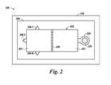
- FIG. 2is a schematic diagram of an apparatus 220 including a tamper resistant device 222 in accordance with a number of embodiments of the present disclosure.
- the tamper resistant device 222can be configured to enclose an apparatus such as apparatus 100 described in FIGS. 1A and 1B .
- the apparatus 220includes the tamper resistant device 222 , the PCB 204 , a screw 226 , and the cover 202 including the hinge 208 , a first portion 201 , a second portion 203 , an opening 224 , and a number of soldering tips 206 - 1 , . . . , 206 -N.
- the tamper resistant device 222can serve as a “black box” within a vehicle.
- the tamper resistant device 222can be attached to a vehicle and can include features to deter the tamper resistant device 222 from being accessed by unauthorized personnel.
- the tamper resistant device 222can prevent a user of a vehicle (e.g. driver, owner, and/or passenger) from modifying and/or removing data.
- the tamper resistant device 222can also include features to indicate if the tamper resistant device 222 has been accessed.
- the tamper resistant device 222can include anti-tamper sealers and/or tamper evident labels.
- the cover 202can include the opening 224 for the screw 226 to lock the cover 202 to the PCB 204 .
- the cover 202can also include the hinge 208 .
- the hinge 208can connect a first portion 201 of the cover 202 and a second portion 203 of the cover 202 .
- the cover 202can be in an open position when the screw 226 is removed from the opening 224 in the cover 202 .
- the first portion 201 of the cover 202can pivot from a closed position to an open position, for example.
Landscapes
- Engineering & Computer Science (AREA)
- Computer Hardware Design (AREA)
- Theoretical Computer Science (AREA)
- Physics & Mathematics (AREA)
- General Physics & Mathematics (AREA)
- Microelectronics & Electronic Packaging (AREA)
- Computer Security & Cryptography (AREA)
- General Engineering & Computer Science (AREA)
- Software Systems (AREA)
- Computer Vision & Pattern Recognition (AREA)
- Artificial Intelligence (AREA)
- Condensed Matter Physics & Semiconductors (AREA)
- Manufacturing & Machinery (AREA)
- Power Engineering (AREA)
- Casings For Electric Apparatus (AREA)
- Storage Device Security (AREA)
- Time Recorders, Dirve Recorders, Access Control (AREA)
Abstract
Description
Claims (23)
Priority Applications (3)
| Application Number | Priority Date | Filing Date | Title |
|---|---|---|---|
| US15/672,423US10490943B2 (en) | 2017-08-09 | 2017-08-09 | Securing a memory card |
| CN201810894274.8ACN109389201B (en) | 2017-08-09 | 2018-08-08 | Fixed memory card |
| US16/543,903US10855031B2 (en) | 2017-08-09 | 2019-08-19 | Securing a memory card |
Applications Claiming Priority (1)
| Application Number | Priority Date | Filing Date | Title |
|---|---|---|---|
| US15/672,423US10490943B2 (en) | 2017-08-09 | 2017-08-09 | Securing a memory card |
Related Child Applications (1)
| Application Number | Title | Priority Date | Filing Date |
|---|---|---|---|
| US16/543,903ContinuationUS10855031B2 (en) | 2017-08-09 | 2019-08-19 | Securing a memory card |
Publications (2)
| Publication Number | Publication Date |
|---|---|
| US20190050703A1 US20190050703A1 (en) | 2019-02-14 |
| US10490943B2true US10490943B2 (en) | 2019-11-26 |
Family
ID=65275361
Family Applications (2)
| Application Number | Title | Priority Date | Filing Date |
|---|---|---|---|
| US15/672,423Active2038-04-24US10490943B2 (en) | 2017-08-09 | 2017-08-09 | Securing a memory card |
| US16/543,903ActiveUS10855031B2 (en) | 2017-08-09 | 2019-08-19 | Securing a memory card |
Family Applications After (1)
| Application Number | Title | Priority Date | Filing Date |
|---|---|---|---|
| US16/543,903ActiveUS10855031B2 (en) | 2017-08-09 | 2019-08-19 | Securing a memory card |
Country Status (2)
| Country | Link |
|---|---|
| US (2) | US10490943B2 (en) |
| CN (1) | CN109389201B (en) |
Cited By (1)
| Publication number | Priority date | Publication date | Assignee | Title |
|---|---|---|---|---|
| US20190372271A1 (en)* | 2017-08-09 | 2019-12-05 | Micron Technology, Inc. | Securing a memory card |
Citations (18)
| Publication number | Priority date | Publication date | Assignee | Title |
|---|---|---|---|---|
| US5687592A (en) | 1993-07-23 | 1997-11-18 | Dell Usa, L.P. | Mechanical lock for a removable hard disk drive and a removable memory card |
| US5822183A (en)* | 1996-04-25 | 1998-10-13 | Olympus Optical Co. Ltd. | Memory card installing device |
| US6512454B2 (en) | 2000-05-24 | 2003-01-28 | International Business Machines Corporation | Tamper resistant enclosure for an electronic device and electrical assembly utilizing same |
| US6894606B2 (en) | 2000-11-22 | 2005-05-17 | Fred Forbes | Vehicular black box monitoring system |
| US20050245136A1 (en)* | 2004-04-29 | 2005-11-03 | Hao Yin | Memory card connector with metal cover and ground terminals |
| US7049970B2 (en)* | 2003-10-22 | 2006-05-23 | International Business Machines Corporation | Tamper sensing method and apparatus |
| US7247791B2 (en)* | 2004-05-27 | 2007-07-24 | Pitney Bowes Inc. | Security barrier for electronic circuitry |
| US7787256B2 (en)* | 2007-08-10 | 2010-08-31 | Gore Enterprise Holdings, Inc. | Tamper respondent system |
| US20120108102A1 (en)* | 2009-07-13 | 2012-05-03 | Jung-Hoon Kim | Socket for Small Card |
| US20130102262A1 (en)* | 2011-10-20 | 2013-04-25 | Zte (Usa) Inc. | All-Outdoor Microwave Enclosure Having a Built-In Memory Cardholder |
| US20160055356A1 (en)* | 2014-08-22 | 2016-02-25 | Hon Hai Precision Industry Co., Ltd. | Anti-data theft structures and electronic devices with the same |
| US20160072209A1 (en)* | 2014-09-05 | 2016-03-10 | Hzo, Inc. | Waterproof sockets and ports |
| US9426904B2 (en)* | 2014-07-09 | 2016-08-23 | Harris Corporation | Communication device in which an unauthorized removal of an electrical connector is detected |
| US9521764B2 (en)* | 2013-12-09 | 2016-12-13 | Timothy Steiner | Tamper respondent apparatus |
| US9633318B2 (en) | 2005-12-08 | 2017-04-25 | Smartdrive Systems, Inc. | Vehicle event recorder systems |
| US9637134B2 (en) | 2005-06-01 | 2017-05-02 | Allstate Insurance Company | Motor vehicle operating data collection and analysis |
| US20190050703A1 (en)* | 2017-08-09 | 2019-02-14 | Micron Technology, Inc. | Securing a memory card |
| US10321589B2 (en)* | 2016-09-19 | 2019-06-11 | International Business Machines Corporation | Tamper-respondent assembly with sensor connection adapter |
Family Cites Families (11)
| Publication number | Priority date | Publication date | Assignee | Title |
|---|---|---|---|---|
| US6686539B2 (en)* | 2001-01-03 | 2004-02-03 | International Business Machines Corporation | Tamper-responding encapsulated enclosure having flexible protective mesh structure |
| DE10321251A1 (en)* | 2003-05-12 | 2004-12-09 | Siemens Ag | Card receiving device and method |
| GB2412996B (en)* | 2004-04-08 | 2008-11-12 | Gore & Ass | Tamper respondent covering |
| US7487265B2 (en)* | 2004-04-16 | 2009-02-03 | Sandisk Corporation | Memory card with two standard sets of contacts and a hinged contact covering mechanism |
| JP2006202156A (en)* | 2005-01-21 | 2006-08-03 | Seiko Epson Corp | Memory card connector |
| US7341461B1 (en)* | 2006-09-18 | 2008-03-11 | Chant Sincere Co., Ltd. | Memory card adapter |
| JP5489118B2 (en)* | 2010-01-28 | 2014-05-14 | 健治 吉田 | Input/output devices, information input/output systems |
| US8523072B2 (en)* | 2011-12-13 | 2013-09-03 | Parabit Systems, Inc. | Card reader protection system |
| US9128662B2 (en)* | 2011-12-23 | 2015-09-08 | Novachips Canada Inc. | Solid state drive memory system |
| US9391662B2 (en)* | 2013-04-30 | 2016-07-12 | Samsung Electronics Co., Ltd | Portable electronic device, flip-type cover of the portable electronic device, and method for controlling the flip-type cover |
| CN205451269U (en)* | 2015-12-25 | 2016-08-10 | 福建索天信息科技股份有限公司 | A ware of punching card for bus |
- 2017
- 2017-08-09USUS15/672,423patent/US10490943B2/enactiveActive
- 2018
- 2018-08-08CNCN201810894274.8Apatent/CN109389201B/enactiveActive
- 2019
- 2019-08-19USUS16/543,903patent/US10855031B2/enactiveActive
Patent Citations (18)
| Publication number | Priority date | Publication date | Assignee | Title |
|---|---|---|---|---|
| US5687592A (en) | 1993-07-23 | 1997-11-18 | Dell Usa, L.P. | Mechanical lock for a removable hard disk drive and a removable memory card |
| US5822183A (en)* | 1996-04-25 | 1998-10-13 | Olympus Optical Co. Ltd. | Memory card installing device |
| US6512454B2 (en) | 2000-05-24 | 2003-01-28 | International Business Machines Corporation | Tamper resistant enclosure for an electronic device and electrical assembly utilizing same |
| US6894606B2 (en) | 2000-11-22 | 2005-05-17 | Fred Forbes | Vehicular black box monitoring system |
| US7049970B2 (en)* | 2003-10-22 | 2006-05-23 | International Business Machines Corporation | Tamper sensing method and apparatus |
| US20050245136A1 (en)* | 2004-04-29 | 2005-11-03 | Hao Yin | Memory card connector with metal cover and ground terminals |
| US7247791B2 (en)* | 2004-05-27 | 2007-07-24 | Pitney Bowes Inc. | Security barrier for electronic circuitry |
| US9637134B2 (en) | 2005-06-01 | 2017-05-02 | Allstate Insurance Company | Motor vehicle operating data collection and analysis |
| US9633318B2 (en) | 2005-12-08 | 2017-04-25 | Smartdrive Systems, Inc. | Vehicle event recorder systems |
| US7787256B2 (en)* | 2007-08-10 | 2010-08-31 | Gore Enterprise Holdings, Inc. | Tamper respondent system |
| US20120108102A1 (en)* | 2009-07-13 | 2012-05-03 | Jung-Hoon Kim | Socket for Small Card |
| US20130102262A1 (en)* | 2011-10-20 | 2013-04-25 | Zte (Usa) Inc. | All-Outdoor Microwave Enclosure Having a Built-In Memory Cardholder |
| US9521764B2 (en)* | 2013-12-09 | 2016-12-13 | Timothy Steiner | Tamper respondent apparatus |
| US9426904B2 (en)* | 2014-07-09 | 2016-08-23 | Harris Corporation | Communication device in which an unauthorized removal of an electrical connector is detected |
| US20160055356A1 (en)* | 2014-08-22 | 2016-02-25 | Hon Hai Precision Industry Co., Ltd. | Anti-data theft structures and electronic devices with the same |
| US20160072209A1 (en)* | 2014-09-05 | 2016-03-10 | Hzo, Inc. | Waterproof sockets and ports |
| US10321589B2 (en)* | 2016-09-19 | 2019-06-11 | International Business Machines Corporation | Tamper-respondent assembly with sensor connection adapter |
| US20190050703A1 (en)* | 2017-08-09 | 2019-02-14 | Micron Technology, Inc. | Securing a memory card |
Cited By (2)
| Publication number | Priority date | Publication date | Assignee | Title |
|---|---|---|---|---|
| US20190372271A1 (en)* | 2017-08-09 | 2019-12-05 | Micron Technology, Inc. | Securing a memory card |
| US10855031B2 (en)* | 2017-08-09 | 2020-12-01 | Micron Technology, Inc. | Securing a memory card |
Also Published As
| Publication number | Publication date |
|---|---|
| US20190372271A1 (en) | 2019-12-05 |
| US10855031B2 (en) | 2020-12-01 |
| CN109389201B (en) | 2022-03-25 |
| CN109389201A (en) | 2019-02-26 |
| US20190050703A1 (en) | 2019-02-14 |
Similar Documents
| Publication | Publication Date | Title |
|---|---|---|
| DE60122853T2 (en) | Method and device for storing data in an integrated circuit | |
| EP1296214B1 (en) | Method for activating a control unit mounted in a housing protected against unauthorised data access | |
| DE102018114266B4 (en) | Non-volatile storage device with secure reading | |
| WO2004099947A3 (en) | Memory protection systems and methods for writable memory | |
| FR2646942A1 (en) | MAP WITH INTEGRATED CIRCUIT | |
| DE102015106741B4 (en) | BRINGING DEVICE AND ACCESSORIES TOGETHER | |
| DE102011082184A1 (en) | Security protection for memory contents of processor main memory | |
| US10855031B2 (en) | Securing a memory card | |
| EP1399797B1 (en) | Control unit | |
| DE112019007421T5 (en) | STORAGE DEVICE WITH SECURE TEST MODE ENTRY | |
| DE102004015546B4 (en) | An integrated circuit semiconductor chip and method for securing a semiconductor integrated circuit | |
| EP2137703B1 (en) | Detection device | |
| EP1956514A1 (en) | Card reader with manipulation recognition | |
| EP2987392B1 (en) | Electronic device | |
| EP1694539A1 (en) | Control device with deactivatable interface | |
| JP2009220922A (en) | Medicine storage system | |
| US8380918B2 (en) | Non-volatile storage alteration tracking | |
| DE19809574A1 (en) | Security identification system for objects | |
| EP1998182B1 (en) | Electric device equipped with a microwave sensor | |
| DE202021105858U1 (en) | Transponder marked weapon element | |
| DE69806272T2 (en) | METHOD AND DEVICE FOR PROTECTING THE IDENTITY OF AN OBJECT | |
| DE202005022130U1 (en) | Security module for controlling and controlling a data traffic of a personal computer | |
| DE102012206726A1 (en) | Method for determining the originality of a component | |
| DE102007027935A1 (en) | Portable data carrier and method for personalizing a portable data carrier | |
| DE202013011130U1 (en) | chip system |
Legal Events
| Date | Code | Title | Description |
|---|---|---|---|
| AS | Assignment | Owner name:MICRON TECHNOLOGY, INC., IDAHO Free format text:ASSIGNMENT OF ASSIGNORS INTEREST;ASSIGNOR:TROIA, ALBERTO;REEL/FRAME:043240/0526 Effective date:20170809 | |
| STPP | Information on status: patent application and granting procedure in general | Free format text:DOCKETED NEW CASE - READY FOR EXAMINATION | |
| AS | Assignment | Owner name:U.S. BANK NATIONAL ASSOCIATION, AS COLLATERAL AGEN Free format text:SUPPLEMENT NO. 6 TO PATENT SECURITY AGREEMENT;ASSIGNOR:MICRON TECHNOLOGY, INC.;REEL/FRAME:044348/0253 Effective date:20171023 Owner name:MORGAN STANLEY SENIOR FUNDING, INC., AS COLLATERAL Free format text:SUPPLEMENT NO. 6 TO PATENT SECURITY AGREEMENT;ASSIGNOR:MICRON TECHNOLOGY, INC.;REEL/FRAME:044653/0333 Effective date:20171023 Owner name:U.S. BANK NATIONAL ASSOCIATION, AS COLLATERAL AGENT, MINNESOTA Free format text:SUPPLEMENT NO. 6 TO PATENT SECURITY AGREEMENT;ASSIGNOR:MICRON TECHNOLOGY, INC.;REEL/FRAME:044348/0253 Effective date:20171023 Owner name:MORGAN STANLEY SENIOR FUNDING, INC., AS COLLATERAL AGENT, MARYLAND Free format text:SUPPLEMENT NO. 6 TO PATENT SECURITY AGREEMENT;ASSIGNOR:MICRON TECHNOLOGY, INC.;REEL/FRAME:044653/0333 Effective date:20171023 | |
| AS | Assignment | Owner name:JPMORGAN CHASE BANK, N.A., AS COLLATERAL AGENT, IL Free format text:SECURITY INTEREST;ASSIGNORS:MICRON TECHNOLOGY, INC.;MICRON SEMICONDUCTOR PRODUCTS, INC.;REEL/FRAME:047540/0001 Effective date:20180703 Owner name:JPMORGAN CHASE BANK, N.A., AS COLLATERAL AGENT, ILLINOIS Free format text:SECURITY INTEREST;ASSIGNORS:MICRON TECHNOLOGY, INC.;MICRON SEMICONDUCTOR PRODUCTS, INC.;REEL/FRAME:047540/0001 Effective date:20180703 | |
| AS | Assignment | Owner name:MICRON TECHNOLOGY, INC., IDAHO Free format text:RELEASE BY SECURED PARTY;ASSIGNOR:U.S. BANK NATIONAL ASSOCIATION, AS AGENT;REEL/FRAME:046597/0333 Effective date:20180629 | |
| STPP | Information on status: patent application and granting procedure in general | Free format text:NON FINAL ACTION MAILED | |
| STPP | Information on status: patent application and granting procedure in general | Free format text:RESPONSE TO NON-FINAL OFFICE ACTION ENTERED AND FORWARDED TO EXAMINER | |
| STPP | Information on status: patent application and granting procedure in general | Free format text:NOTICE OF ALLOWANCE MAILED -- APPLICATION RECEIVED IN OFFICE OF PUBLICATIONS | |
| AS | Assignment | Owner name:MICRON TECHNOLOGY, INC., CALIFORNIA Free format text:RELEASE BY SECURED PARTY;ASSIGNOR:MORGAN STANLEY SENIOR FUNDING, INC., AS COLLATERAL AGENT;REEL/FRAME:050709/0838 Effective date:20190731 | |
| STPP | Information on status: patent application and granting procedure in general | Free format text:PUBLICATIONS -- ISSUE FEE PAYMENT VERIFIED | |
| STCF | Information on status: patent grant | Free format text:PATENTED CASE | |
| AS | Assignment | Owner name:MICRON TECHNOLOGY, INC., IDAHO Free format text:RELEASE BY SECURED PARTY;ASSIGNOR:JPMORGAN CHASE BANK, N.A., AS COLLATERAL AGENT;REEL/FRAME:051028/0001 Effective date:20190731 Owner name:MICRON SEMICONDUCTOR PRODUCTS, INC., IDAHO Free format text:RELEASE BY SECURED PARTY;ASSIGNOR:JPMORGAN CHASE BANK, N.A., AS COLLATERAL AGENT;REEL/FRAME:051028/0001 Effective date:20190731 | |
| MAFP | Maintenance fee payment | Free format text:PAYMENT OF MAINTENANCE FEE, 4TH YEAR, LARGE ENTITY (ORIGINAL EVENT CODE: M1551); ENTITY STATUS OF PATENT OWNER: LARGE ENTITY Year of fee payment:4 |