US10486052B2 - Driving mode changeable mobility device - Google Patents
Driving mode changeable mobility deviceDownload PDFInfo
- Publication number
- US10486052B2 US10486052B2US15/807,738US201715807738AUS10486052B2US 10486052 B2US10486052 B2US 10486052B2US 201715807738 AUS201715807738 AUS 201715807738AUS 10486052 B2US10486052 B2US 10486052B2
- Authority
- US
- United States
- Prior art keywords
- base panel
- mobility device
- driving mode
- wheels
- wheel
- Prior art date
- Legal status (The legal status is an assumption and is not a legal conclusion. Google has not performed a legal analysis and makes no representation as to the accuracy of the status listed.)
- Active, expires
Links
- 230000008878couplingEffects0.000claimsdescription26
- 238000010168coupling processMethods0.000claimsdescription26
- 238000005859coupling reactionMethods0.000claimsdescription26
- 230000002452interceptive effectEffects0.000claimsdescription3
- 230000007423decreaseEffects0.000description3
- 238000000034methodMethods0.000description3
- 238000010586diagramMethods0.000description2
- 238000013500data storageMethods0.000description1
- 230000007257malfunctionEffects0.000description1
- 230000003287optical effectEffects0.000description1
Images


Classifications
- B—PERFORMING OPERATIONS; TRANSPORTING
- B62—LAND VEHICLES FOR TRAVELLING OTHERWISE THAN ON RAILS
- B62K—CYCLES; CYCLE FRAMES; CYCLE STEERING DEVICES; RIDER-OPERATED TERMINAL CONTROLS SPECIALLY ADAPTED FOR CYCLES; CYCLE AXLE SUSPENSIONS; CYCLE SIDE-CARS, FORECARS, OR THE LIKE
- B62K5/00—Cycles with handlebars, equipped with three or more main road wheels
- B62K5/01—Motorcycles with four or more wheels
- A—HUMAN NECESSITIES
- A63—SPORTS; GAMES; AMUSEMENTS
- A63C—SKATES; SKIS; ROLLER SKATES; DESIGN OR LAYOUT OF COURTS, RINKS OR THE LIKE
- A63C17/00—Roller skates; Skate-boards
- A63C17/12—Roller skates; Skate-boards with driving mechanisms
- A—HUMAN NECESSITIES
- A63—SPORTS; GAMES; AMUSEMENTS
- A63C—SKATES; SKIS; ROLLER SKATES; DESIGN OR LAYOUT OF COURTS, RINKS OR THE LIKE
- A63C17/00—Roller skates; Skate-boards
- A63C17/01—Skateboards
- A63C17/014—Wheel arrangements
- A63C17/015—Wheel arrangements with wheels arranged in two pairs
- A—HUMAN NECESSITIES
- A63—SPORTS; GAMES; AMUSEMENTS
- A63C—SKATES; SKIS; ROLLER SKATES; DESIGN OR LAYOUT OF COURTS, RINKS OR THE LIKE
- A63C17/00—Roller skates; Skate-boards
- A63C17/14—Roller skates; Skate-boards with brakes, e.g. toe stoppers, freewheel roller clutches
- B—PERFORMING OPERATIONS; TRANSPORTING
- B60—VEHICLES IN GENERAL
- B60K—ARRANGEMENT OR MOUNTING OF PROPULSION UNITS OR OF TRANSMISSIONS IN VEHICLES; ARRANGEMENT OR MOUNTING OF PLURAL DIVERSE PRIME-MOVERS IN VEHICLES; AUXILIARY DRIVES FOR VEHICLES; INSTRUMENTATION OR DASHBOARDS FOR VEHICLES; ARRANGEMENTS IN CONNECTION WITH COOLING, AIR INTAKE, GAS EXHAUST OR FUEL SUPPLY OF PROPULSION UNITS IN VEHICLES
- B60K17/00—Arrangement or mounting of transmissions in vehicles
- B60K17/34—Arrangement or mounting of transmissions in vehicles for driving both front and rear wheels, e.g. four wheel drive vehicles
- B60K17/358—Arrangement or mounting of transmissions in vehicles for driving both front and rear wheels, e.g. four wheel drive vehicles all driven wheels being steerable
- B—PERFORMING OPERATIONS; TRANSPORTING
- B60—VEHICLES IN GENERAL
- B60K—ARRANGEMENT OR MOUNTING OF PROPULSION UNITS OR OF TRANSMISSIONS IN VEHICLES; ARRANGEMENT OR MOUNTING OF PLURAL DIVERSE PRIME-MOVERS IN VEHICLES; AUXILIARY DRIVES FOR VEHICLES; INSTRUMENTATION OR DASHBOARDS FOR VEHICLES; ARRANGEMENTS IN CONNECTION WITH COOLING, AIR INTAKE, GAS EXHAUST OR FUEL SUPPLY OF PROPULSION UNITS IN VEHICLES
- B60K7/00—Disposition of motor in, or adjacent to, traction wheel
- B60K7/0007—Disposition of motor in, or adjacent to, traction wheel the motor being electric
- B—PERFORMING OPERATIONS; TRANSPORTING
- B62—LAND VEHICLES FOR TRAVELLING OTHERWISE THAN ON RAILS
- B62B—HAND-PROPELLED VEHICLES, e.g. HAND CARTS OR PERAMBULATORS; SLEDGES
- B62B5/00—Accessories or details specially adapted for hand carts
- B62B5/0026—Propulsion aids
- B62B5/0033—Electric motors
- B62B5/0036—Arrangements of motors
- B—PERFORMING OPERATIONS; TRANSPORTING
- B62—LAND VEHICLES FOR TRAVELLING OTHERWISE THAN ON RAILS
- B62K—CYCLES; CYCLE FRAMES; CYCLE STEERING DEVICES; RIDER-OPERATED TERMINAL CONTROLS SPECIALLY ADAPTED FOR CYCLES; CYCLE AXLE SUSPENSIONS; CYCLE SIDE-CARS, FORECARS, OR THE LIKE
- B62K11/00—Motorcycles, engine-assisted cycles or motor scooters with one or two wheels
- B62K11/14—Handlebar constructions, or arrangements of controls thereon, specially adapted thereto
- A—HUMAN NECESSITIES
- A63—SPORTS; GAMES; AMUSEMENTS
- A63C—SKATES; SKIS; ROLLER SKATES; DESIGN OR LAYOUT OF COURTS, RINKS OR THE LIKE
- A63C17/00—Roller skates; Skate-boards
- A63C17/008—Roller skates; Skate-boards with retractable wheel, i.e. movable relative to the chassis out of contact from surface
- A—HUMAN NECESSITIES
- A63—SPORTS; GAMES; AMUSEMENTS
- A63C—SKATES; SKIS; ROLLER SKATES; DESIGN OR LAYOUT OF COURTS, RINKS OR THE LIKE
- A63C17/00—Roller skates; Skate-boards
- A63C17/01—Skateboards
- A63C17/011—Skateboards with steering mechanisms
- A—HUMAN NECESSITIES
- A63—SPORTS; GAMES; AMUSEMENTS
- A63C—SKATES; SKIS; ROLLER SKATES; DESIGN OR LAYOUT OF COURTS, RINKS OR THE LIKE
- A63C2203/00—Special features of skates, skis, roller-skates, snowboards and courts
- A63C2203/06—Special features of skates, skis, roller-skates, snowboards and courts enabling conversion into another device
- A—HUMAN NECESSITIES
- A63—SPORTS; GAMES; AMUSEMENTS
- A63C—SKATES; SKIS; ROLLER SKATES; DESIGN OR LAYOUT OF COURTS, RINKS OR THE LIKE
- A63C2203/00—Special features of skates, skis, roller-skates, snowboards and courts
- A63C2203/12—Electrically powered or heated
- A—HUMAN NECESSITIES
- A63—SPORTS; GAMES; AMUSEMENTS
- A63C—SKATES; SKIS; ROLLER SKATES; DESIGN OR LAYOUT OF COURTS, RINKS OR THE LIKE
- A63C2203/00—Special features of skates, skis, roller-skates, snowboards and courts
- A63C2203/18—Measuring a physical parameter, e.g. speed, distance
- A—HUMAN NECESSITIES
- A63—SPORTS; GAMES; AMUSEMENTS
- A63C—SKATES; SKIS; ROLLER SKATES; DESIGN OR LAYOUT OF COURTS, RINKS OR THE LIKE
- A63C2203/00—Special features of skates, skis, roller-skates, snowboards and courts
- A63C2203/24—Processing or storing data, e.g. with electronic chip
- B—PERFORMING OPERATIONS; TRANSPORTING
- B60—VEHICLES IN GENERAL
- B60Y—INDEXING SCHEME RELATING TO ASPECTS CROSS-CUTTING VEHICLE TECHNOLOGY
- B60Y2200/00—Type of vehicle
- B60Y2200/80—Other vehicles not covered by groups B60Y2200/10 - B60Y2200/60
- B60Y2200/81—Toys
Definitions
- the present inventionrelates to a driving mode changeable mobility device, and more particularly, to a small mobility device capable of changing a driving direction to a right angle by changing a phase of a wheel coupled to a base panel by 90°.
- small mobility devicesare being developed as personal transport equipment.
- these mobility devicesare mostly configured to have one or two wheels.
- a small mobility device with four wheelshas the advantage of being physically stable and robust against malfunctions of control.
- an inter-axis distancethat is, a distance between a center of a front wheel and a center of a rear wheel is an important consideration.
- the small mobility devices with four wheelsbecome more suitable for low speed driving indoors. Additionally, as the inter-axis distance increases, the small mobility devices with four wheels become more suitable for high speed driving at high speed outdoors. Therefore, there has been a problem that the mobility device suitable for low speed driving and the mobility suitable for high speed driving have to be designed differently.
- An object of the present inventionis to provide a driving mode changeable mobility device that changes a phase of a wheel coupled to a base panel of the mobility device by 90° to change a driving direction, thereby changing a driving mode to a low speed driving mode and a high speed driving mode.
- a mobility devicemay include: a base panel configured to support a passenger; a plurality of wheels disposed at a plurality of points of the base panel and coupled to the base panel to be rotated with respect to a vertical axis; a rotary portion configured to provide a rotational force to rotate the wheel with respect to the base panel; and a braking portion disposed on a rotary portion to control the plurality of wheels to be rotated with respect to the base panel or positions of the plurality of wheels to be fixed.
- a driving direction of the base panelmay be changed by a rotation of the wheel by rotating the braking portion clockwise or counterclockwise.
- the mobility devicemay further include: a controller (e.g., a fust controller) configured to adjust a rotation of the braking portion, in which the base panel may have a rectangular shape including a long side and a short side, the plurality of wheels may be disposed at each edge of the base panel, and the controller may be configured to adjust the rotation of the braking portion in a high speed mode to adjust each wheel to be horizontal to the long side of the base panel and adjust the rotation of the braking portion in a low speed mode to adjust each wheel to be horizontal to the short side of the base panel.
- a controllere.g., a fust controller
- the wheelmay be positioned at an outside of an edge of the base panel, a rotational axis in a vertical direction may be positioned at an inside of the edge of the base panel, and the edge of the base panel may be bent in an arc shape not to interfere with the edge of the base panel when the wheel is rotated.
- the plurality of wheelsmay each include driving motors that drive each wheel independently.
- the mobility devicemay further include: a controller (e.g., a second controller) configured to operate a plurality of driving motors, in which the controller may be configured to adjust a rotational speed of each of the driving motors to be different to steer the base panel.
- the first and second controllersmay be integrated as a single controller.
- the base panelmay include a plurality of force sensors and the controller may be steered based on a difference between values sensed by the plurality of force sensors.
- the plurality of force sensorsmay be disposed at a location where a passenger's foot is supported in the base panel.
- the plurality of force sensorsmay include a left sensor disposed where a left foot of a passenger is supported and a right sensor disposed where a right foot of a passenger is supported.
- the left sensormay be configured to include a left front sensor disposed in front of where the left foot of the passenger is supported and a left rear sensor disposed at the rear thereof
- the right sensormay be configured to include a right front sensor disposed in front of where the right foot of the passenger is supported and a right rear sensor disposed at the rear thereof.
- the controllermay be configured to steer (e.g., adjust) left-right directions of the base panel based on the difference between the a value sensed by the left sensor and a value sensed by the right sensor, and forward or rearward movement of the base panel may be adjusted based on the difference between a value sensed by the left front sensor and the right front sensor and a value sensed by the left rear sensor and the right rear sensor.
- the rotary portionmay include a rotating body, a link, and a braking portion.
- the rotating bodymay be disposed on each wheel and coupled to the base panel via a vertical axis to rotate the wheel when the rotating body is rotated and the braking portion, the braking portion may be rotated on the base panel, and the link may be configured to transfer a rotational force of the braking portion to each rotating body to rotate a rotating body.
- the rotary portionmay further include a straight portion (e.g., a linear portion) provided to correspond to each rotating body, and the straight portion may be connected to the rotating body and may be configured to move linearly to rotate the rotating body.
- a straight portion coupling bodymay be formed by coupling a plurality of straight portions connected to a plurality of adjacent rotating bodies, respectively.
- a first end of the linkmay be coupled to the braking portion and a second end thereof may be coupled to the straight portion coupling body and the link and the straight portion coupling body may be configured to move linearly by the rotational force of the braking portion to rotate the rotating body.
- the rotary portionmay further include a guide portion having a fust side coupled to the base panel and a second side coupled to the straight portion coupling body, and the guide portion may be configured to linearly guide the movement of the straight portion coupling body by the linear movement of the link.
- the rotary portion and the breaking portionmay be disposed on the plurality of wheels, respectively to control each of the wheels to be rotated with respect to the base panel or the positions of each of the wheels to be fixed.
- FIGS. 1A and 1Bare diagrams showing two driving modes of a mobility device according to an exemplary embodiment of the present invention
- FIG. 2is a top perspective view of a high speed mode state of a mobility device according to an exemplary embodiment of the present invention.
- FIG. 3is a bottom view of a low speed mode state of a mobility device according to an exemplary embodiment of the present invention.
- controller/control unitrefers to a hardware device that includes a memory and a processor.
- the memoryis configured to store the modules and the processor is specifically configured to execute said modules to perform one or more processes which are described further below.
- control logic of the present inventionmay be embodied as non-transitory computer readable media on a computer readable medium containing executable program instructions executed by a processor, controller/control unit or the like.
- the computer readable mediumsinclude, but are not limited to, ROM, RAM, compact disc (CD)-ROMs, magnetic tapes, floppy disks, flash drives, smart cards and optical data storage devices.
- the computer readable recording mediumcan also be distributed in network coupled computer systems so that the computer readable media is stored and executed in a distributed fashion, e.g., by a telematics server or a Controller Area Network (CAN).
- a telematics serveror a Controller Area Network (CAN).
- CANController Area Network
- the term “about”is understood as within a range of normal tolerance in the art, for example within 2 standard deviations of the mean “About” can be understood as within 10%, 9%, 8%, 7%, 6%, 5%, 4%, 3%, 2%, 1%, 0.5%, 0.1%, 0.05%, or 0.01% of the stated value. Unless otherwise clear from the context, all numerical values provided herein are modified by the term “about.”
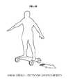
- FIGS. 1A-1Bare diagrams showing two driving modes of a mobility device according to an exemplary embodiment of the present invention.
- the mobility device discussed hereinmay be referred to as a small mobility device merely being an indication of the relatively small size of the mobility device on which one person is capable of standing.
- FIG. 1Ashows a mode in which a small mobility device drives at a low speed indoors
- FIG. 1Bshows a mode in which a small mobility device drives at a high speed outdoors. As shown in the FIG.
- a mobility devicedrives while a wheel is fixed in a horizontal direction to a short side of a base panel, an inter-axis distance is short or minimal, thereby facilitating cornering in a narrow alley (e.g., making a turn), and as shown in the FIG. 1B , when a small mobility device drives while the wheel is fixed in a horizontal direction to a long side of the base panel, the inter-axis distance is longer, thereby improving the stability of linear driving.
- a mobility devicedrives a side surface having a relatively narrower area than a front surface of a passenger.
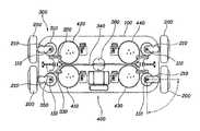
- FIG. 2is a top perspective view of a high speed mode state of a mobility device according to an exemplary embodiment of the present invention
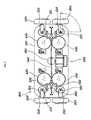
- FIG. 3is a bottom view of a low speed mode state of a mobility device according to an exemplary embodiment of the present invention.
- the mobility devicemay include a base panel 100 that supports a passenger; a plurality of wheels 200 disposed at a plurality of points of the base panel 100 , respectively and coupled to the base panel 100 to be rotated with respect to a vertical axis; a rotary portion 300 that provides a rotational force to rotate the wheel 200 with respect to the base panel 100 ; and a braking portion 360 disposed on the rotary portion and configured to operate and adjust the plurality of wheels to be rotated with respect to the base panel or positions thereof to be fixed to the base panel.
- the base panel 100supports boarding (e.g., boarding of a user onto the device), and is generally configured of a footstool on which a passenger rides while standing up and configured to support the feet of a passenger.
- the base panel 10may also be designed to allow a passenger to sit on the base panel 10 during operation.
- a driving direction of the base panel 100may be changed by a rotation of the wheel 200 by rotating the braking portion 360 clockwise or counterclockwise.
- the base panel 100may have a rectangular shape including a long side and a short side (e.g., a short side being shorter in length than the long side and the rectangular shape having two long sides and two short sides), and the plurality of wheels 200 may be disposed/mounted/coupled at each edge of the base panel 100 sequentially and thus may be formed in four.
- the plurality of wheels 200may be rotated at an angle of 90° inwardly of the edges of the base panel 100 , and thus the driving direction may be changed at a right angle.
- the mobility devicemay further include a controller (not shown) configured to adjust the rotation of the braking portion 360 .
- the controllermay be configured to adjust the rotation of the braking portion 360 in a high speed mode to cause each wheel 200 to be horizontal to the long side of the base panel 100 and may be configured to adjust the rotation of the braking portion 360 in a low speed mode to cause each wheel 200 to be horizontal to the short side of the base panel 100 .
- each wheel 200may be horizontal to the long side of the base panel 100 to increase an inter-axis distance during linear operation of the device (e.g., driving), thereby improving linear driving performance.
- each wheel 200may be horizontal to the short side of the base panel 100 to decrease the inter-axis distance during the linear operation of the device (e.g., driving), thereby reducing a turning radius.
- the rotation control of the braking portion 360may be performed to fix the braking portion 360 during operate and to rotate the braking portion 360 only when the wheel stops for safety.
- the control of the braking portion by the controllermay use a remote control or the like to perform a mode change between the high speed mode and the low speed mode. It may also be possible to rotate the braking portion 360 manually without the controller (not shown).
- a change angle of the driving directionmay vary based on a shape, an edge angle or the like of the base panel 100 .
- the edge of the base panel 100may be bent in an arc shape, the wheel 200 may be positioned at an outside of the edge of the base panel 100 , and a rotational axis in a vertical direction may be positioned at an inside of the edge of the base panel 100 to prevent the wheel 200 from interfering with the base panel 100 when being rotated.
- the edge of the base panel 100may be bent in an arc shape to prevent the wheel 200 from interfering with the edge of the base panel 100 when the wheel 200 is rotated.
- the turning radius in the vertical direction of the wheel 200 and an arc radius of the edge of the base panel 100may substantially coincide with each other.
- the plurality of wheels 200may each include with driving motors (not shown) configured to independently drive the respective wheels 200 .
- An in-wheel motormay be mounted inside each of the plurality of wheels 200 , and thus the wheel 200 may be driven independently.
- the mobility devicemay further include the controller configured to operate the plurality of driving motors (not shown), in which the controller may be configured to adjust the rotational speed of each of the driving motors to be different, thereby steering the base panel 100 .
- the controllermay be provided separately in each of the driving motors configured to independently drive the plurality of wheels 200 to adjust the rotational speed of each driving motor and the wheel 200 .
- the controllermay be configured to operate the plurality of driving motors to adjust the rotational speeds of the respective driving motors and the wheel 200 .
- the base panel 100may include a plurality of force sensors 400 and the controller may be configured to steer the base panel 100 based on a difference between values sensed by the plurality of force sensors 400 .
- the plurality of force sensors 400may be disposed at a location where a passenger's foot is supported on the base panel 100 and may be provided as a 1-axis force sensor configured to measure a vertical direction to measure a force in a vertical direction by a passenger's weight.
- the plurality of force sensors 400may include left sensors 410 and 420 disposed at a location where a left foot of a passenger is supported and right sensors 430 and 440 disposed at a location where a right foot of a passenger is supported on the base panel 100 .
- the left-right directions of the base panelmay be made based on a difference in values sensed by the left sensors 410 and 420 and the right sensors 430 and 440 .
- the sensorsmay be disposed in front of and in back of the passenger's foot, respectively, and the controller may be configured to adjust the forward or rearward movement of the mobility device based on the difference between the values sensed by the front sensors 410 and 430 and the rear sensors 420 and 440 .
- the left sensors 410 and 420may include a left front sensor 410 disposed in front of a part and a left rear sensor 420 disposed at the rear thereof, where the left foot of the passenger is supported
- the right sensors 430 and 440may include a right front sensor 430 disposed in front of a part and a right rear sensor 440 disposed at the rear thereof, where the right foot of the passenger is supported on the mobility device.
- the controllermay be configured to steer and adjust the left-right directions of the base panel based on the difference between the values sensed by the left sensors 410 and 420 and the values sensed by the right sensors 430 and 440 . Further, the forward movement or rearward movement of the base panel may be adjusted based on the difference between the values sensed by the left front sensor 410 and the right front sensor 430 and the values sensed by the left rear sensor 420 and the right rear sensor 440 . The controller may further be configured to adjust the speed of the forward or rearward movement as the difference between the values sensed by the front sensors 410 and 430 and the values sensed by the rear sensors 420 and 440 increases.
- FIG. 3shows left/right and front/rear directions when the wheel 200 is fixed in a horizontal direction to the short side of the base panel 100 and
- FIG. 2shows the change in the left/right and front/rear directions when the wheel 200 is fixed in the horizontal direction to the long side of the base panel 100 .
- the rotary portion 300may include a rotating body 310 , a straight portion 320 , a straight portion assembly 330 , a link 340 , and a braking portion 360 .
- the rotating body 310may be disposed on each wheel 200 via a knuckle 210 and the rotating body 310 may be coupled to the base panel 100 via a vertical axis 110 , and thus, the wheel 200 may be rotated when the rotating body 310 is rotated.
- the straight portion 320may correspond to each of the rotating bodies 310 and may be configured to move linearly while being connected to the rotating body 310 to rotate the rotating body 310 .
- the rotating body 310 and the straight portion 320may each be configured of a pinion gear and a rack gear, and may be configured of various systems in which linear movement is converted into rotary movement, such as a system using friction force or a system using a wire.
- a straight portion coupling body 330may be formed by coupling the plurality of straight portions 320 connected to a plurality of adjacent rotating bodies, respectively. As shown in FIG. 3 , the straight portion coupling body 330 may be formed by coupling the straight portions 320 positioned on the left and right sides, or the straight portion coupling body may be formed by coupling straight portions positioned on the front and rear sides. In particular, the adjacent straight portions 320 may be configured to move in the same direction by the same length to simplify the configuration of the link.
- the braking portion 360may be rotated on the base panel 100 and the link 340 may have a first end coupled to the braking portion 360 and a second end coupled to the straight portion coupling body 330 . Accordingly, the link 340 and the straight portion coupling body 330 may be configured to move linearly by the rotational force of the braking portion 360 , and thus, the rotating body 310 may be rotated and the connected wheel 200 may be thus rotated with respect to the vertical axis.
- the rotary portion 300may further include a guide portion 350 having a fust side coupled to the base panel 100 and a second side coupled to the straight portion coupling body 330 . The guide portion 350 may be configured to linearly guide the movement of the straight portion coupling body 330 by the linear movement of the link 340 .
- the guide portion 350may be further provided to allow the straight portion coupling body 330 to move linearly without being rotated and the link 340 may be rotatably coupled to the braking portion 360 and the straight portion coupling body 330 , respectively, by a hinge or the like to allow the straight portion coupling body 330 to move linearly along the guide portion 350 .
- the guide portion 350may have a separate structure in which one side is coupled to the base panel 100 or the guide portion 350 may also be formed by forming grooves on the base panel 100 along a movement path of the straight portion coupling body 330 .
- the rotary portion and the breaking portionmay be disposed on the plurality of wheels 200 , respectively to operate each of the wheels 200 to be rotated with respect to the base panel 100 or the positions of each of the wheels 200 to be fixed.
- the corneringmay be executed successfully in a narrow space through the driving mode in which the inter-axis distance is minimal when the a mobility device drives at low speed indoors and the straight stability may be improved through the driving mode in which the inter-axis distance is increased when the mobility device drives at high speed outdoors, such that the mobility device may be used indoors and outdoors.
- the phase of the wheelmay be fixed during the driving by the braking portion, thereby changing the driving mode more stably.
Landscapes
- Engineering & Computer Science (AREA)
- Mechanical Engineering (AREA)
- Chemical & Material Sciences (AREA)
- Combustion & Propulsion (AREA)
- Transportation (AREA)
- Motorcycle And Bicycle Frame (AREA)
Abstract
Description
Claims (16)
Applications Claiming Priority (2)
| Application Number | Priority Date | Filing Date | Title |
|---|---|---|---|
| KR1020170072659AKR102288888B1 (en) | 2017-06-09 | 2017-06-09 | Driving mode changeable small mobility |
| KR10-2017-0072659 | 2017-06-09 |
Publications (2)
| Publication Number | Publication Date |
|---|---|
| US20180353840A1 US20180353840A1 (en) | 2018-12-13 |
| US10486052B2true US10486052B2 (en) | 2019-11-26 |
Family
ID=64562852
Family Applications (1)
| Application Number | Title | Priority Date | Filing Date |
|---|---|---|---|
| US15/807,738Active2038-01-02US10486052B2 (en) | 2017-06-09 | 2017-11-09 | Driving mode changeable mobility device |
Country Status (3)
| Country | Link |
|---|---|
| US (1) | US10486052B2 (en) |
| KR (1) | KR102288888B1 (en) |
| CN (1) | CN109018119B (en) |
Cited By (14)
| Publication number | Priority date | Publication date | Assignee | Title |
|---|---|---|---|---|
| US10744396B2 (en)* | 2016-03-22 | 2020-08-18 | Ford Global Technologies, Llc | Configurable transportation structure |
| US11374509B2 (en) | 2020-10-23 | 2022-06-28 | Honda Motor Co., Ltd. | Generator pulley system and methods thereof |
| US11583754B2 (en)* | 2015-08-26 | 2023-02-21 | Joseph L. Pikulski | Mobilized platforms |
| US11584455B2 (en)* | 2016-05-27 | 2023-02-21 | Joseph L. Pikulski | Motorized platforms |
| WO2023056340A1 (en)* | 2021-09-30 | 2023-04-06 | Razor Usa Llc | Personal mobility vehicles with adjustable wheel positions |
| US20230322285A1 (en)* | 2020-08-28 | 2023-10-12 | Maenhout | Collapsible shopping trolley with auxiliary electric motor |
| US11844998B2 (en) | 2019-09-18 | 2023-12-19 | Razor Usa Llc | Caster boards with removable insert |
| USD1012217S1 (en) | 2016-09-02 | 2024-01-23 | Razor Usa Llc | Powered wheeled board |
| US11951382B2 (en) | 2019-03-06 | 2024-04-09 | Razor Usa Llc | Powered wheeled board |
| US12042716B2 (en) | 2017-04-18 | 2024-07-23 | Razor Usa Llc | Powered wheeled board |
| US12134025B2 (en) | 2014-11-26 | 2024-11-05 | Razor Usa Llc | Powered wheeled board |
| US20250050746A1 (en)* | 2023-08-07 | 2025-02-13 | Hyundai Motor Company | Method of controlling driving of a plurality of mobility devices connected by a pivot mechanism |
| USD1077110S1 (en) | 2015-05-04 | 2025-05-27 | Razor Usa Llc | Skateboard |
| US12434127B2 (en) | 2020-09-29 | 2025-10-07 | Razor Usa Llc | Convertible caster board |
Citations (25)
| Publication number | Priority date | Publication date | Assignee | Title |
|---|---|---|---|---|
| US4295547A (en)* | 1980-03-31 | 1981-10-20 | Dungan D Patrick | Brake assembly for small vehicles |
| US5020621A (en)* | 1989-12-19 | 1991-06-04 | Martin Christopher V | Electric motor powered skateboard with integral brakes |
| US5864333A (en)* | 1996-02-26 | 1999-01-26 | O'heir; Brian S. | Foot force actuated computer input apparatus and method |
| US6123348A (en)* | 1996-12-17 | 2000-09-26 | M & R Innovations, Llc | Brake system for downhill wheeled board |
| US6488296B2 (en)* | 2000-02-17 | 2002-12-03 | Richard D. Ireton | Method and apparatus for small wheel disc brake |
| US6592486B1 (en)* | 1999-08-10 | 2003-07-15 | The Swatch Group Management Services Ag | Drive unit for a vehicle with a continuously variable transmission |
| US6647719B2 (en)* | 2001-02-17 | 2003-11-18 | Globemag L.P. | Hydraulic oscillator as a drive of machines |
| US6655936B2 (en)* | 2001-11-14 | 2003-12-02 | Delphi Technologies, Inc. | Rotary vane pump with under-vane pump |
| US6659480B1 (en)* | 1999-07-28 | 2003-12-09 | Benjamin John Newman | Skate board brake |
| US6820881B1 (en)* | 2002-08-21 | 2004-11-23 | Gregory A. Berry | Skateboard brake |
| US7134223B2 (en)* | 2002-07-23 | 2006-11-14 | Sewing Innovations And Machine Co. | Elastomeric sole for use with converted flatbed sewing machine |
| US7159879B2 (en)* | 2004-11-02 | 2007-01-09 | Jeffrey Cole | Braking and steering system for a truck, wheeled platform, skateboard or vehicle |
| US7216876B2 (en)* | 2004-06-21 | 2007-05-15 | Cole Jeffrey E | Occupant-propelled fluid powered rotary device, truck, wheeled platform, or vehicle |
| US7635136B2 (en)* | 2005-06-21 | 2009-12-22 | Jeffrey E. Cole | Truck assembly for a skateboard, wheeled platform, or vehicle |
| US8251384B1 (en)* | 2008-11-12 | 2012-08-28 | Other Planet Products, Inc. | Axle and suspension |
| US8371594B2 (en)* | 2009-06-10 | 2013-02-12 | James Stewart Palmer | Speed control system |
| US20130081891A1 (en)* | 2011-10-04 | 2013-04-04 | Boosted Boards | Personal transport vehicle |
| KR101320958B1 (en) | 2013-03-18 | 2013-10-29 | 주식회사 에스에이 | A manual guided vehicle with a transter device of the driving direction |
| KR20140073069A (en) | 2012-12-06 | 2014-06-16 | 현대자동차주식회사 | Rear wheel steering device for vehicle |
| US9004213B2 (en)* | 2012-02-10 | 2015-04-14 | Intuitive Motion, Inc. | Electric motorized skateboard with an actuator assembly with a footpad and force sensor |
| KR101539027B1 (en) | 2013-12-24 | 2015-07-29 | 한국과학기술원 | Steering Instrument for Automobile Drived by In-wheel Motor System and Method for Steering Using the Same |
| US9132338B2 (en)* | 2010-09-08 | 2015-09-15 | Thomas P. Cassidy | Deck wheeled device |
| US9504902B1 (en)* | 2015-05-27 | 2016-11-29 | Wellesley Johnson | Skateboard braking system |
| US9504903B2 (en)* | 2012-05-14 | 2016-11-29 | Brakeboard Pty Ltd | Braking apparatus for a recreational riding board apparatus |
| US9616318B2 (en)* | 2013-03-15 | 2017-04-11 | Stealth Electric Longboards | Powered personal transportation systems and methods |
Family Cites Families (7)
| Publication number | Priority date | Publication date | Assignee | Title |
|---|---|---|---|---|
| US7370713B1 (en)* | 1993-02-24 | 2008-05-13 | Deka Products Limited Partnership | Personal mobility vehicles and methods |
| JP2787766B2 (en)* | 1995-06-30 | 1998-08-20 | 有限会社ニューテクノロジー研究所 | Self-propelled roller board |
| KR100804774B1 (en)* | 2006-07-14 | 2008-02-19 | 김지철 | Play equipment |
| CN202163544U (en)* | 2011-07-14 | 2012-03-14 | 宁波市海曙劲飞信息技术有限公司 | Motor-driven skateboard |
| JP5578627B2 (en)* | 2011-09-21 | 2014-08-27 | 小林 行紘 | 4-wheel bicycle rear-wheel drive shock absorber |
| WO2014047732A1 (en)* | 2012-09-29 | 2014-04-03 | Clayton Benjamin Daniel | Freestyle board sports device |
| CN203844903U (en)* | 2014-04-25 | 2014-09-24 | 沈光玉 | Safe four-wheeler |
- 2017
- 2017-06-09KRKR1020170072659Apatent/KR102288888B1/enactiveActive
- 2017-11-09USUS15/807,738patent/US10486052B2/enactiveActive
- 2017-12-06CNCN201711272686.XApatent/CN109018119B/enactiveActive
Patent Citations (25)
| Publication number | Priority date | Publication date | Assignee | Title |
|---|---|---|---|---|
| US4295547A (en)* | 1980-03-31 | 1981-10-20 | Dungan D Patrick | Brake assembly for small vehicles |
| US5020621A (en)* | 1989-12-19 | 1991-06-04 | Martin Christopher V | Electric motor powered skateboard with integral brakes |
| US5864333A (en)* | 1996-02-26 | 1999-01-26 | O'heir; Brian S. | Foot force actuated computer input apparatus and method |
| US6123348A (en)* | 1996-12-17 | 2000-09-26 | M & R Innovations, Llc | Brake system for downhill wheeled board |
| US6659480B1 (en)* | 1999-07-28 | 2003-12-09 | Benjamin John Newman | Skate board brake |
| US6592486B1 (en)* | 1999-08-10 | 2003-07-15 | The Swatch Group Management Services Ag | Drive unit for a vehicle with a continuously variable transmission |
| US6488296B2 (en)* | 2000-02-17 | 2002-12-03 | Richard D. Ireton | Method and apparatus for small wheel disc brake |
| US6647719B2 (en)* | 2001-02-17 | 2003-11-18 | Globemag L.P. | Hydraulic oscillator as a drive of machines |
| US6655936B2 (en)* | 2001-11-14 | 2003-12-02 | Delphi Technologies, Inc. | Rotary vane pump with under-vane pump |
| US7134223B2 (en)* | 2002-07-23 | 2006-11-14 | Sewing Innovations And Machine Co. | Elastomeric sole for use with converted flatbed sewing machine |
| US6820881B1 (en)* | 2002-08-21 | 2004-11-23 | Gregory A. Berry | Skateboard brake |
| US7216876B2 (en)* | 2004-06-21 | 2007-05-15 | Cole Jeffrey E | Occupant-propelled fluid powered rotary device, truck, wheeled platform, or vehicle |
| US7159879B2 (en)* | 2004-11-02 | 2007-01-09 | Jeffrey Cole | Braking and steering system for a truck, wheeled platform, skateboard or vehicle |
| US7635136B2 (en)* | 2005-06-21 | 2009-12-22 | Jeffrey E. Cole | Truck assembly for a skateboard, wheeled platform, or vehicle |
| US8251384B1 (en)* | 2008-11-12 | 2012-08-28 | Other Planet Products, Inc. | Axle and suspension |
| US8371594B2 (en)* | 2009-06-10 | 2013-02-12 | James Stewart Palmer | Speed control system |
| US9132338B2 (en)* | 2010-09-08 | 2015-09-15 | Thomas P. Cassidy | Deck wheeled device |
| US20130081891A1 (en)* | 2011-10-04 | 2013-04-04 | Boosted Boards | Personal transport vehicle |
| US9004213B2 (en)* | 2012-02-10 | 2015-04-14 | Intuitive Motion, Inc. | Electric motorized skateboard with an actuator assembly with a footpad and force sensor |
| US9504903B2 (en)* | 2012-05-14 | 2016-11-29 | Brakeboard Pty Ltd | Braking apparatus for a recreational riding board apparatus |
| KR20140073069A (en) | 2012-12-06 | 2014-06-16 | 현대자동차주식회사 | Rear wheel steering device for vehicle |
| US9616318B2 (en)* | 2013-03-15 | 2017-04-11 | Stealth Electric Longboards | Powered personal transportation systems and methods |
| KR101320958B1 (en) | 2013-03-18 | 2013-10-29 | 주식회사 에스에이 | A manual guided vehicle with a transter device of the driving direction |
| KR101539027B1 (en) | 2013-12-24 | 2015-07-29 | 한국과학기술원 | Steering Instrument for Automobile Drived by In-wheel Motor System and Method for Steering Using the Same |
| US9504902B1 (en)* | 2015-05-27 | 2016-11-29 | Wellesley Johnson | Skateboard braking system |
Cited By (20)
| Publication number | Priority date | Publication date | Assignee | Title |
|---|---|---|---|---|
| US12134025B2 (en) | 2014-11-26 | 2024-11-05 | Razor Usa Llc | Powered wheeled board |
| USD1077110S1 (en) | 2015-05-04 | 2025-05-27 | Razor Usa Llc | Skateboard |
| US12324977B2 (en)* | 2015-08-26 | 2025-06-10 | Joseph L. Pikulski | Mobilized platforms |
| US11583754B2 (en)* | 2015-08-26 | 2023-02-21 | Joseph L. Pikulski | Mobilized platforms |
| US20230302346A1 (en)* | 2015-08-26 | 2023-09-28 | Joseph L. Pikulski | Mobilized platforms |
| US10744396B2 (en)* | 2016-03-22 | 2020-08-18 | Ford Global Technologies, Llc | Configurable transportation structure |
| US11584455B2 (en)* | 2016-05-27 | 2023-02-21 | Joseph L. Pikulski | Motorized platforms |
| US20230294778A1 (en)* | 2016-05-27 | 2023-09-21 | Joseph L. Pikulski | Motorized platforms |
| USD1012217S1 (en) | 2016-09-02 | 2024-01-23 | Razor Usa Llc | Powered wheeled board |
| US12042716B2 (en) | 2017-04-18 | 2024-07-23 | Razor Usa Llc | Powered wheeled board |
| US11951382B2 (en) | 2019-03-06 | 2024-04-09 | Razor Usa Llc | Powered wheeled board |
| US11844998B2 (en) | 2019-09-18 | 2023-12-19 | Razor Usa Llc | Caster boards with removable insert |
| US12201891B2 (en) | 2019-09-18 | 2025-01-21 | Razor Usa Llc | Caster boards with removable insert |
| US20230322285A1 (en)* | 2020-08-28 | 2023-10-12 | Maenhout | Collapsible shopping trolley with auxiliary electric motor |
| US12263877B2 (en)* | 2020-08-28 | 2025-04-01 | Maenhout | Collapsible shopping trolley with auxiliary electric motor |
| US12434127B2 (en) | 2020-09-29 | 2025-10-07 | Razor Usa Llc | Convertible caster board |
| US11374509B2 (en) | 2020-10-23 | 2022-06-28 | Honda Motor Co., Ltd. | Generator pulley system and methods thereof |
| US12053690B2 (en) | 2021-09-30 | 2024-08-06 | Razor Usa Llc | Personal mobility vehicles with adjustable wheel positions |
| WO2023056340A1 (en)* | 2021-09-30 | 2023-04-06 | Razor Usa Llc | Personal mobility vehicles with adjustable wheel positions |
| US20250050746A1 (en)* | 2023-08-07 | 2025-02-13 | Hyundai Motor Company | Method of controlling driving of a plurality of mobility devices connected by a pivot mechanism |
Also Published As
| Publication number | Publication date |
|---|---|
| KR20180134644A (en) | 2018-12-19 |
| KR102288888B1 (en) | 2021-08-12 |
| US20180353840A1 (en) | 2018-12-13 |
| CN109018119A (en) | 2018-12-18 |
| CN109018119B (en) | 2021-07-23 |
Similar Documents
| Publication | Publication Date | Title |
|---|---|---|
| US10486052B2 (en) | Driving mode changeable mobility device | |
| CN106275170B (en) | Posture vehicle | |
| JP6167717B2 (en) | Suspension device | |
| US11124034B2 (en) | Height adjustment module and robot system including the same | |
| US11491989B2 (en) | Vehicle using eccentric wheel | |
| CN106560387A (en) | Electric self-balancing vehicle | |
| CN112930295B (en) | Steering handle of vehicle | |
| JP6902728B2 (en) | Mobile | |
| KR102778280B1 (en) | Movable Object | |
| US20180370582A1 (en) | Personal transporter | |
| JP3656500B2 (en) | Omnidirectional cart | |
| JP2962364B2 (en) | Electric car | |
| WO2003086561A1 (en) | Car model | |
| US10532787B2 (en) | Compact mobile device having adjustable drive mode | |
| CN217415878U (en) | Wheel steering device and vehicle with same | |
| JP4662125B2 (en) | Caster wheel support device | |
| WO2019111560A1 (en) | Control device for mobile robot and mobile robot system | |
| KR20240031748A (en) | Movable object | |
| JP2009223561A (en) | Route changing method and device for unmanned carrier system | |
| KR20040103376A (en) | Motor vehicle | |
| JP4583834B2 (en) | Omnidirectional vehicle | |
| US20190322328A1 (en) | Vehicle | |
| JP3657464B2 (en) | caster | |
| JP6722916B2 (en) | vehicle | |
| JP6944409B2 (en) | Mechanical parking device |
Legal Events
| Date | Code | Title | Description |
|---|---|---|---|
| AS | Assignment | Owner name:HYUNDAI MOTOR COMPANY, KOREA, REPUBLIC OF Free format text:ASSIGNMENT OF ASSIGNORS INTEREST;ASSIGNOR:CHOI, JAE YOUNG;REEL/FRAME:044079/0341 Effective date:20171102 Owner name:KIA MOTORS CORPORATION, KOREA, REPUBLIC OF Free format text:ASSIGNMENT OF ASSIGNORS INTEREST;ASSIGNOR:CHOI, JAE YOUNG;REEL/FRAME:044079/0341 Effective date:20171102 | |
| FEPP | Fee payment procedure | Free format text:ENTITY STATUS SET TO UNDISCOUNTED (ORIGINAL EVENT CODE: BIG.); ENTITY STATUS OF PATENT OWNER: LARGE ENTITY | |
| AS | Assignment | Owner name:HYUNDAI MOTOR COMPANY, KOREA, REPUBLIC OF Free format text:ASSIGNMENT OF ASSIGNORS INTEREST;ASSIGNOR:CHOI, JAE YOUNG;REEL/FRAME:045883/0411 Effective date:20171102 Owner name:KIA MOTORS CORPORATION, KOREA, REPUBLIC OF Free format text:ASSIGNMENT OF ASSIGNORS INTEREST;ASSIGNOR:CHOI, JAE YOUNG;REEL/FRAME:045883/0411 Effective date:20171102 | |
| STPP | Information on status: patent application and granting procedure in general | Free format text:DOCKETED NEW CASE - READY FOR EXAMINATION | |
| STPP | Information on status: patent application and granting procedure in general | Free format text:NOTICE OF ALLOWANCE MAILED -- APPLICATION RECEIVED IN OFFICE OF PUBLICATIONS | |
| STPP | Information on status: patent application and granting procedure in general | Free format text:PUBLICATIONS -- ISSUE FEE PAYMENT VERIFIED | |
| STCF | Information on status: patent grant | Free format text:PATENTED CASE | |
| MAFP | Maintenance fee payment | Free format text:PAYMENT OF MAINTENANCE FEE, 4TH YEAR, LARGE ENTITY (ORIGINAL EVENT CODE: M1551); ENTITY STATUS OF PATENT OWNER: LARGE ENTITY Year of fee payment:4 |