US10485891B2 - Multi-function dressing structure for negative-pressure therapy - Google Patents
Multi-function dressing structure for negative-pressure therapyDownload PDFInfo
- Publication number
- US10485891B2 US10485891B2US14/869,731US201514869731AUS10485891B2US 10485891 B2US10485891 B2US 10485891B2US 201514869731 AUS201514869731 AUS 201514869731AUS 10485891 B2US10485891 B2US 10485891B2
- Authority
- US
- United States
- Prior art keywords
- layer
- fibers
- function core
- absorbing
- ion exchange
- Prior art date
- Legal status (The legal status is an assumption and is not a legal conclusion. Google has not performed a legal analysis and makes no representation as to the accuracy of the status listed.)
- Active, expires
Links
- 238000002560therapeutic procedureMethods0.000titledescription24
- 239000000835fiberSubstances0.000claimsabstractdescription161
- 238000005342ion exchangeMethods0.000claimsabstractdescription56
- 230000000903blocking effectEffects0.000claimsabstractdescription52
- 239000010410layerSubstances0.000claimsdescription386
- 239000002355dual-layerSubstances0.000claimsdescription53
- 239000000463materialSubstances0.000claimsdescription46
- 239000002356single layerSubstances0.000claimsdescription42
- 229920002635polyurethanePolymers0.000claimsdescription28
- 239000004814polyurethaneSubstances0.000claimsdescription28
- OKTJSMMVPCPJKN-UHFFFAOYSA-NCarbonChemical compound[C]OKTJSMMVPCPJKN-UHFFFAOYSA-N0.000claimsdescription22
- 229920000642polymerPolymers0.000claimsdescription19
- 229920001296polysiloxanePolymers0.000claimsdescription14
- 229920000247superabsorbent polymerPolymers0.000claimsdescription13
- 230000002209hydrophobic effectEffects0.000claimsdescription12
- 239000002245particleSubstances0.000claimsdescription12
- -1polyacrylicsPolymers0.000claimsdescription12
- 229920001477hydrophilic polymerPolymers0.000claimsdescription9
- 230000000845anti-microbial effectEffects0.000claimsdescription7
- NIXOWILDQLNWCW-UHFFFAOYSA-Nacrylic acid groupChemical groupC(C=C)(=O)ONIXOWILDQLNWCW-UHFFFAOYSA-N0.000claimsdescription6
- 239000004599antimicrobialSubstances0.000claimsdescription6
- 229920001600hydrophobic polymerPolymers0.000claimsdescription6
- 229920003303ion-exchange polymerPolymers0.000claimsdescription6
- 239000003456ion exchange resinSubstances0.000claimsdescription5
- NBVXSUQYWXRMNV-UHFFFAOYSA-NfluoromethaneChemical compoundFCNBVXSUQYWXRMNV-UHFFFAOYSA-N0.000claimsdescription4
- 229920000728polyesterPolymers0.000claimsdescription4
- 229920002134Carboxymethyl cellulosePolymers0.000claimsdescription2
- 229920002334SpandexPolymers0.000claimsdescription2
- 239000001768carboxy methyl celluloseSubstances0.000claimsdescription2
- 235000010948carboxy methyl celluloseNutrition0.000claimsdescription2
- 239000008112carboxymethyl-celluloseSubstances0.000claimsdescription2
- 229920000058polyacrylatePolymers0.000claimsdescription2
- 239000004332silverSubstances0.000claimsdescription2
- 229910052709silverInorganic materials0.000claimsdescription2
- ZCYVEMRRCGMTRW-UHFFFAOYSA-N7553-56-2Chemical compound[I]ZCYVEMRRCGMTRW-UHFFFAOYSA-N0.000claims1
- 229910052740iodineInorganic materials0.000claims1
- 239000011630iodineSubstances0.000claims1
- 238000000034methodMethods0.000abstractdescription16
- 238000004519manufacturing processMethods0.000abstractdescription14
- 210000001519tissueAnatomy0.000description90
- 239000012530fluidSubstances0.000description64
- 239000007788liquidSubstances0.000description26
- XLYOFNOQVPJJNP-UHFFFAOYSA-NwaterChemical compoundOXLYOFNOQVPJJNP-UHFFFAOYSA-N0.000description19
- 206010052428WoundDiseases0.000description17
- 208000027418Wounds and injuryDiseases0.000description17
- 235000019645odorNutrition0.000description13
- 239000012500ion exchange mediaSubstances0.000description12
- 230000015572biosynthetic processEffects0.000description10
- 150000002500ionsChemical class0.000description10
- 230000001225therapeutic effectEffects0.000description10
- 239000000499gelSubstances0.000description9
- 230000008569processEffects0.000description9
- 239000006260foamSubstances0.000description8
- 239000000203mixtureSubstances0.000description8
- 239000002250absorbentSubstances0.000description7
- 239000003792electrolyteSubstances0.000description7
- 239000008151electrolyte solutionSubstances0.000description7
- 239000000243solutionSubstances0.000description7
- 230000002745absorbentEffects0.000description6
- 150000001450anionsChemical class0.000description6
- 230000008901benefitEffects0.000description6
- 150000001768cationsChemical class0.000description6
- 239000006185dispersionSubstances0.000description6
- 230000006870functionEffects0.000description6
- 239000007789gasSubstances0.000description5
- 230000014759maintenance of locationEffects0.000description5
- 239000000126substanceSubstances0.000description5
- 239000010457zeoliteSubstances0.000description5
- FAPWRFPIFSIZLT-UHFFFAOYSA-MSodium chlorideChemical compound[Na+].[Cl-]FAPWRFPIFSIZLT-UHFFFAOYSA-M0.000description4
- 230000010261cell growthEffects0.000description4
- 230000037361pathwayEffects0.000description4
- 239000011148porous materialSubstances0.000description4
- 238000007789sealingMethods0.000description4
- 102000008186CollagenHuman genes0.000description3
- 108010035532CollagenProteins0.000description3
- PEDCQBHIVMGVHV-UHFFFAOYSA-NGlycerineChemical compoundOCC(O)COPEDCQBHIVMGVHV-UHFFFAOYSA-N0.000description3
- 229920000954PolyglycolidePolymers0.000description3
- 230000002378acidificating effectEffects0.000description3
- 229920001436collagenPolymers0.000description3
- 238000004132cross linkingMethods0.000description3
- 230000007423decreaseEffects0.000description3
- 238000009826distributionMethods0.000description3
- 238000001523electrospinningMethods0.000description3
- 210000002615epidermisAnatomy0.000description3
- 239000001257hydrogenSubstances0.000description3
- 229910052739hydrogenInorganic materials0.000description3
- 238000002074melt spinningMethods0.000description3
- 239000000178monomerSubstances0.000description3
- 230000035699permeabilityEffects0.000description3
- 239000004633polyglycolic acidSubstances0.000description3
- 239000000376reactantSubstances0.000description3
- 150000003839saltsChemical class0.000description3
- 210000003491skinAnatomy0.000description3
- 239000002904solventSubstances0.000description3
- 238000010557suspension polymerization reactionMethods0.000description3
- 238000002166wet spinningMethods0.000description3
- DGAQECJNVWCQMB-PUAWFVPOSA-MIlexoside XXIXChemical compoundC[C@@H]1CC[C@@]2(CC[C@@]3(C(=CC[C@H]4[C@]3(CC[C@@H]5[C@@]4(CC[C@@H](C5(C)C)OS(=O)(=O)[O-])C)C)[C@@H]2[C@]1(C)O)C)C(=O)O[C@H]6[C@@H]([C@H]([C@@H]([C@H](O6)CO)O)O)O.[Na+]DGAQECJNVWCQMB-PUAWFVPOSA-M0.000description2
- 239000004793PolystyreneSubstances0.000description2
- 208000025865UlcerDiseases0.000description2
- 238000009825accumulationMethods0.000description2
- 239000000853adhesiveSubstances0.000description2
- 230000001070adhesive effectEffects0.000description2
- 125000004429atomChemical group0.000description2
- 230000004888barrier functionEffects0.000description2
- 239000011324beadSubstances0.000description2
- 238000009954braidingMethods0.000description2
- 229910052799carbonInorganic materials0.000description2
- 238000006243chemical reactionMethods0.000description2
- 230000001112coagulating effectEffects0.000description2
- 239000011248coating agentSubstances0.000description2
- 238000000576coating methodMethods0.000description2
- 238000011161developmentMethods0.000description2
- 230000005684electric fieldEffects0.000description2
- 210000000416exudates and transudateAnatomy0.000description2
- 239000006261foam materialSubstances0.000description2
- 238000010528free radical solution polymerization reactionMethods0.000description2
- 230000012010growthEffects0.000description2
- 239000000416hydrocolloidSubstances0.000description2
- 239000000017hydrogelSubstances0.000description2
- 125000004435hydrogen atomChemical group[H]*0.000description2
- 125000002887hydroxy groupChemical group[H]O*0.000description2
- 208000014674injuryDiseases0.000description2
- 239000004745nonwoven fabricSubstances0.000description2
- 239000004626polylactic acidSubstances0.000description2
- 238000006116polymerization reactionMethods0.000description2
- 229920002223polystyrenePolymers0.000description2
- 239000011734sodiumSubstances0.000description2
- 229910052708sodiumInorganic materials0.000description2
- 239000011780sodium chlorideSubstances0.000description2
- 238000009987spinningMethods0.000description2
- 238000003860storageMethods0.000description2
- 239000000758substrateSubstances0.000description2
- 230000008733traumaEffects0.000description2
- 231100000397ulcerToxicity0.000description2
- 238000009941weavingMethods0.000description2
- SMZOUWXMTYCWNB-UHFFFAOYSA-N2-(2-methoxy-5-methylphenyl)ethanamineChemical compoundCOC1=CC=C(C)C=C1CCNSMZOUWXMTYCWNB-UHFFFAOYSA-N0.000description1
- NIXOWILDQLNWCW-UHFFFAOYSA-MAcrylateChemical compound[O-]C(=O)C=CNIXOWILDQLNWCW-UHFFFAOYSA-M0.000description1
- OYPRJOBELJOOCE-UHFFFAOYSA-NCalciumChemical compound[Ca]OYPRJOBELJOOCE-UHFFFAOYSA-N0.000description1
- 239000004215Carbon black (E152)Substances0.000description1
- 235000014653Carica parvifloraNutrition0.000description1
- VEXZGXHMUGYJMC-UHFFFAOYSA-MChloride anionChemical compound[Cl-]VEXZGXHMUGYJMC-UHFFFAOYSA-M0.000description1
- 241000243321CnidariaSpecies0.000description1
- 206010063560Excessive granulation tissueDiseases0.000description1
- UFHFLCQGNIYNRP-UHFFFAOYSA-NHydrogenChemical compound[H][H]UFHFLCQGNIYNRP-UHFFFAOYSA-N0.000description1
- 102000002274Matrix MetalloproteinasesHuman genes0.000description1
- 108010000684Matrix MetalloproteinasesProteins0.000description1
- 229920002550PolyAPTACPolymers0.000description1
- 239000004721Polyphenylene oxideSubstances0.000description1
- 229920005830Polyurethane FoamPolymers0.000description1
- 239000004372Polyvinyl alcoholSubstances0.000description1
- ZLMJMSJWJFRBEC-UHFFFAOYSA-NPotassiumChemical compound[K]ZLMJMSJWJFRBEC-UHFFFAOYSA-N0.000description1
- 239000004820Pressure-sensitive adhesiveSubstances0.000description1
- 229920001247Reticulated foamPolymers0.000description1
- 229910021536ZeoliteInorganic materials0.000description1
- 238000010521absorption reactionMethods0.000description1
- 239000002253acidSubstances0.000description1
- 150000007513acidsChemical class0.000description1
- 150000003926acrylamidesChemical class0.000description1
- 239000003522acrylic cementSubstances0.000description1
- 229920006397acrylic thermoplasticPolymers0.000description1
- 230000001154acute effectEffects0.000description1
- 210000000577adipose tissueAnatomy0.000description1
- 229910001579aluminosilicate mineralInorganic materials0.000description1
- JEWHCPOELGJVCB-UHFFFAOYSA-Naluminum;calcium;oxido-[oxido(oxo)silyl]oxy-oxosilane;potassium;sodium;tridecahydrateChemical compoundO.O.O.O.O.O.O.O.O.O.O.O.O.[Na].[Al].[K].[Ca].[O-][Si](=O)O[Si]([O-])=OJEWHCPOELGJVCB-UHFFFAOYSA-N0.000description1
- JYIBXUUINYLWLR-UHFFFAOYSA-Naluminum;calcium;potassium;silicon;sodium;trihydrateChemical compoundO.O.O.[Na].[Al].[Si].[K].[Ca]JYIBXUUINYLWLR-UHFFFAOYSA-N0.000description1
- 229910052908analcimeInorganic materials0.000description1
- 238000004458analytical methodMethods0.000description1
- QVGXLLKOCUKJST-UHFFFAOYSA-Natomic oxygenChemical compound[O]QVGXLLKOCUKJST-UHFFFAOYSA-N0.000description1
- 230000001580bacterial effectEffects0.000description1
- 235000012216bentoniteNutrition0.000description1
- 230000033228biological regulationEffects0.000description1
- 230000017531blood circulationEffects0.000description1
- 210000000988bone and boneAnatomy0.000description1
- 239000011575calciumSubstances0.000description1
- 229910052791calciumInorganic materials0.000description1
- 239000001506calcium phosphateSubstances0.000description1
- 229910000389calcium phosphateInorganic materials0.000description1
- 235000011010calcium phosphatesNutrition0.000description1
- UNYSKUBLZGJSLV-UHFFFAOYSA-Lcalcium;1,3,5,2,4,6$l^{2}-trioxadisilaluminane 2,4-dioxide;dihydroxide;hexahydrateChemical compoundO.O.O.O.O.O.[OH-].[OH-].[Ca+2].O=[Si]1O[Al]O[Si](=O)O1.O=[Si]1O[Al]O[Si](=O)O1UNYSKUBLZGJSLV-UHFFFAOYSA-L0.000description1
- 150000004649carbonic acid derivativesChemical class0.000description1
- 238000009960cardingMethods0.000description1
- 210000000845cartilageAnatomy0.000description1
- 125000002091cationic groupChemical group0.000description1
- 230000001413cellular effectEffects0.000description1
- 229910052676chabaziteInorganic materials0.000description1
- 238000012412chemical couplingMethods0.000description1
- 230000001684chronic effectEffects0.000description1
- 239000004927claySubstances0.000description1
- 229910001603clinoptiloliteInorganic materials0.000description1
- 239000008139complexing agentSubstances0.000description1
- 150000001875compoundsChemical class0.000description1
- 210000002808connective tissueAnatomy0.000description1
- 238000010924continuous productionMethods0.000description1
- 229920001577copolymerPolymers0.000description1
- 230000008878couplingEffects0.000description1
- 238000010168coupling processMethods0.000description1
- 238000005859coupling reactionMethods0.000description1
- 229920006037cross link polymerPolymers0.000description1
- 239000003431cross linking reagentSubstances0.000description1
- 238000010227cup method (microbiological evaluation)Methods0.000description1
- 238000005520cutting processMethods0.000description1
- 230000003247decreasing effectEffects0.000description1
- 230000007547defectEffects0.000description1
- 230000002950deficientEffects0.000description1
- 239000008367deionised waterSubstances0.000description1
- 229910021641deionized waterInorganic materials0.000description1
- 206010012601diabetes mellitusDiseases0.000description1
- 238000010586diagramMethods0.000description1
- GUJOJGAPFQRJSV-UHFFFAOYSA-Ndialuminum;dioxosilane;oxygen(2-);hydrateChemical compoundO.[O-2].[O-2].[O-2].[Al+3].[Al+3].O=[Si]=O.O=[Si]=O.O=[Si]=O.O=[Si]=OGUJOJGAPFQRJSV-UHFFFAOYSA-N0.000description1
- HNPSIPDUKPIQMN-UHFFFAOYSA-Ndioxosilane;oxo(oxoalumanyloxy)alumaneChemical compoundO=[Si]=O.O=[Al]O[Al]=OHNPSIPDUKPIQMN-UHFFFAOYSA-N0.000description1
- 230000002500effect on skinEffects0.000description1
- 230000000694effectsEffects0.000description1
- 210000000981epitheliumAnatomy0.000description1
- 239000004744fabricSubstances0.000description1
- 238000009950feltingMethods0.000description1
- 239000008187granular materialSubstances0.000description1
- 238000005469granulationMethods0.000description1
- 230000003179granulationEffects0.000description1
- 210000001126granulation tissueAnatomy0.000description1
- 230000035876healingEffects0.000description1
- 229910052677heulanditeInorganic materials0.000description1
- 239000003864humusSubstances0.000description1
- 229930195733hydrocarbonNatural products0.000description1
- 150000002430hydrocarbonsChemical class0.000description1
- 230000002706hydrostatic effectEffects0.000description1
- 208000015181infectious diseaseDiseases0.000description1
- 239000003999initiatorSubstances0.000description1
- 230000003993interactionEffects0.000description1
- PNDPGZBMCMUPRI-UHFFFAOYSA-NiodineChemical compoundIIPNDPGZBMCMUPRI-UHFFFAOYSA-N0.000description1
- 230000001788irregularEffects0.000description1
- 230000007794irritationEffects0.000description1
- 238000009940knittingMethods0.000description1
- 210000003041ligamentAnatomy0.000description1
- 239000003446ligandSubstances0.000description1
- 230000007246mechanismEffects0.000description1
- 238000002844meltingMethods0.000description1
- 230000008018meltingEffects0.000description1
- 239000012528membraneSubstances0.000description1
- 230000005012migrationEffects0.000description1
- 238000013508migrationMethods0.000description1
- 238000002156mixingMethods0.000description1
- 238000012986modificationMethods0.000description1
- 230000004048modificationEffects0.000description1
- 229910052901montmorilloniteInorganic materials0.000description1
- 210000003205muscleAnatomy0.000description1
- 229910052674natroliteInorganic materials0.000description1
- 238000009581negative-pressure wound therapyMethods0.000description1
- 230000001537neural effectEffects0.000description1
- 229920000620organic polymerPolymers0.000description1
- 239000001301oxygenSubstances0.000description1
- 229910052760oxygenInorganic materials0.000description1
- 238000004806packaging method and processMethods0.000description1
- 206010033675panniculitisDiseases0.000description1
- 239000006072pasteSubstances0.000description1
- 230000002093peripheral effectEffects0.000description1
- 229910001743phillipsiteInorganic materials0.000description1
- 229920000747poly(lactic acid)Polymers0.000description1
- 229920003229poly(methyl methacrylate)Polymers0.000description1
- 229920001798poly[2-(acrylamido)-2-methyl-1-propanesulfonic acid] polymerPolymers0.000description1
- 229920000515polycarbonatePolymers0.000description1
- 239000004417polycarbonateSubstances0.000description1
- 229920000570polyetherPolymers0.000description1
- 229920006264polyurethane filmPolymers0.000description1
- 239000011496polyurethane foamSubstances0.000description1
- 229920002451polyvinyl alcoholPolymers0.000description1
- 239000011591potassiumSubstances0.000description1
- 229910052700potassiumInorganic materials0.000description1
- 238000012545processingMethods0.000description1
- 239000011347resinSubstances0.000description1
- 229920005989resinPolymers0.000description1
- 239000002689soilSubstances0.000description1
- 239000004747spunlaid nonwovenSubstances0.000description1
- 229910001220stainless steelInorganic materials0.000description1
- 239000010935stainless steelSubstances0.000description1
- 229910052678stilbiteInorganic materials0.000description1
- 210000004304subcutaneous tissueAnatomy0.000description1
- 239000004583superabsorbent polymers (SAPs)Substances0.000description1
- 238000001356surgical procedureMethods0.000description1
- 210000002435tendonAnatomy0.000description1
- ISXSCDLOGDJUNJ-UHFFFAOYSA-Ntert-butyl prop-2-enoateChemical compoundCC(C)(C)OC(=O)C=CISXSCDLOGDJUNJ-UHFFFAOYSA-N0.000description1
- 238000012360testing methodMethods0.000description1
- 238000012546transferMethods0.000description1
- 230000000472traumatic effectEffects0.000description1
- QORWJWZARLRLPR-UHFFFAOYSA-Htricalcium bis(phosphate)Chemical compound[Ca+2].[Ca+2].[Ca+2].[O-]P([O-])([O-])=O.[O-]P([O-])([O-])=OQORWJWZARLRLPR-UHFFFAOYSA-H0.000description1
- 238000011144upstream manufacturingMethods0.000description1
- 230000002792vascularEffects0.000description1
- 201000002282venous insufficiencyDiseases0.000description1
- 238000003466weldingMethods0.000description1
Images


Classifications
- A—HUMAN NECESSITIES
- A61—MEDICAL OR VETERINARY SCIENCE; HYGIENE
- A61L—METHODS OR APPARATUS FOR STERILISING MATERIALS OR OBJECTS IN GENERAL; DISINFECTION, STERILISATION OR DEODORISATION OF AIR; CHEMICAL ASPECTS OF BANDAGES, DRESSINGS, ABSORBENT PADS OR SURGICAL ARTICLES; MATERIALS FOR BANDAGES, DRESSINGS, ABSORBENT PADS OR SURGICAL ARTICLES
- A61L15/00—Chemical aspects of, or use of materials for, bandages, dressings or absorbent pads
- A61L15/16—Bandages, dressings or absorbent pads for physiological fluids such as urine or blood, e.g. sanitary towels, tampons
- A61L15/18—Bandages, dressings or absorbent pads for physiological fluids such as urine or blood, e.g. sanitary towels, tampons containing inorganic materials
- A—HUMAN NECESSITIES
- A61—MEDICAL OR VETERINARY SCIENCE; HYGIENE
- A61F—FILTERS IMPLANTABLE INTO BLOOD VESSELS; PROSTHESES; DEVICES PROVIDING PATENCY TO, OR PREVENTING COLLAPSING OF, TUBULAR STRUCTURES OF THE BODY, e.g. STENTS; ORTHOPAEDIC, NURSING OR CONTRACEPTIVE DEVICES; FOMENTATION; TREATMENT OR PROTECTION OF EYES OR EARS; BANDAGES, DRESSINGS OR ABSORBENT PADS; FIRST-AID KITS
- A61F13/00—Bandages or dressings; Absorbent pads
- A61F13/05—Bandages or dressings; Absorbent pads specially adapted for use with sub-pressure or over-pressure therapy, wound drainage or wound irrigation, e.g. for use with negative-pressure wound therapy [NPWT]
- A61F13/00068—
- A—HUMAN NECESSITIES
- A61—MEDICAL OR VETERINARY SCIENCE; HYGIENE
- A61F—FILTERS IMPLANTABLE INTO BLOOD VESSELS; PROSTHESES; DEVICES PROVIDING PATENCY TO, OR PREVENTING COLLAPSING OF, TUBULAR STRUCTURES OF THE BODY, e.g. STENTS; ORTHOPAEDIC, NURSING OR CONTRACEPTIVE DEVICES; FOMENTATION; TREATMENT OR PROTECTION OF EYES OR EARS; BANDAGES, DRESSINGS OR ABSORBENT PADS; FIRST-AID KITS
- A61F13/00—Bandages or dressings; Absorbent pads
- A61F13/00987—Apparatus or processes for manufacturing non-adhesive dressings or bandages
- A61F13/00991—Apparatus or processes for manufacturing non-adhesive dressings or bandages for treating webs, e.g. for moisturising, coating, impregnating or applying powder
- A—HUMAN NECESSITIES
- A61—MEDICAL OR VETERINARY SCIENCE; HYGIENE
- A61F—FILTERS IMPLANTABLE INTO BLOOD VESSELS; PROSTHESES; DEVICES PROVIDING PATENCY TO, OR PREVENTING COLLAPSING OF, TUBULAR STRUCTURES OF THE BODY, e.g. STENTS; ORTHOPAEDIC, NURSING OR CONTRACEPTIVE DEVICES; FOMENTATION; TREATMENT OR PROTECTION OF EYES OR EARS; BANDAGES, DRESSINGS OR ABSORBENT PADS; FIRST-AID KITS
- A61F13/00—Bandages or dressings; Absorbent pads
- A61F13/02—Adhesive bandages or dressings
- A61F13/0203—Adhesive bandages or dressings with fluid retention members
- A61F13/022—Adhesive bandages or dressings with fluid retention members having more than one layer with different fluid retention characteristics
- A—HUMAN NECESSITIES
- A61—MEDICAL OR VETERINARY SCIENCE; HYGIENE
- A61F—FILTERS IMPLANTABLE INTO BLOOD VESSELS; PROSTHESES; DEVICES PROVIDING PATENCY TO, OR PREVENTING COLLAPSING OF, TUBULAR STRUCTURES OF THE BODY, e.g. STENTS; ORTHOPAEDIC, NURSING OR CONTRACEPTIVE DEVICES; FOMENTATION; TREATMENT OR PROTECTION OF EYES OR EARS; BANDAGES, DRESSINGS OR ABSORBENT PADS; FIRST-AID KITS
- A61F13/00—Bandages or dressings; Absorbent pads
- A61F13/02—Adhesive bandages or dressings
- A61F13/0276—Apparatus or processes for manufacturing adhesive dressings or bandages
- A—HUMAN NECESSITIES
- A61—MEDICAL OR VETERINARY SCIENCE; HYGIENE
- A61L—METHODS OR APPARATUS FOR STERILISING MATERIALS OR OBJECTS IN GENERAL; DISINFECTION, STERILISATION OR DEODORISATION OF AIR; CHEMICAL ASPECTS OF BANDAGES, DRESSINGS, ABSORBENT PADS OR SURGICAL ARTICLES; MATERIALS FOR BANDAGES, DRESSINGS, ABSORBENT PADS OR SURGICAL ARTICLES
- A61L15/00—Chemical aspects of, or use of materials for, bandages, dressings or absorbent pads
- A61L15/16—Bandages, dressings or absorbent pads for physiological fluids such as urine or blood, e.g. sanitary towels, tampons
- A61L15/22—Bandages, dressings or absorbent pads for physiological fluids such as urine or blood, e.g. sanitary towels, tampons containing macromolecular materials
- A61L15/225—Mixtures of macromolecular compounds
- A—HUMAN NECESSITIES
- A61—MEDICAL OR VETERINARY SCIENCE; HYGIENE
- A61L—METHODS OR APPARATUS FOR STERILISING MATERIALS OR OBJECTS IN GENERAL; DISINFECTION, STERILISATION OR DEODORISATION OF AIR; CHEMICAL ASPECTS OF BANDAGES, DRESSINGS, ABSORBENT PADS OR SURGICAL ARTICLES; MATERIALS FOR BANDAGES, DRESSINGS, ABSORBENT PADS OR SURGICAL ARTICLES
- A61L15/00—Chemical aspects of, or use of materials for, bandages, dressings or absorbent pads
- A61L15/16—Bandages, dressings or absorbent pads for physiological fluids such as urine or blood, e.g. sanitary towels, tampons
- A61L15/22—Bandages, dressings or absorbent pads for physiological fluids such as urine or blood, e.g. sanitary towels, tampons containing macromolecular materials
- A61L15/24—Macromolecular compounds obtained by reactions only involving carbon-to-carbon unsaturated bonds; Derivatives thereof
- A—HUMAN NECESSITIES
- A61—MEDICAL OR VETERINARY SCIENCE; HYGIENE
- A61L—METHODS OR APPARATUS FOR STERILISING MATERIALS OR OBJECTS IN GENERAL; DISINFECTION, STERILISATION OR DEODORISATION OF AIR; CHEMICAL ASPECTS OF BANDAGES, DRESSINGS, ABSORBENT PADS OR SURGICAL ARTICLES; MATERIALS FOR BANDAGES, DRESSINGS, ABSORBENT PADS OR SURGICAL ARTICLES
- A61L15/00—Chemical aspects of, or use of materials for, bandages, dressings or absorbent pads
- A61L15/16—Bandages, dressings or absorbent pads for physiological fluids such as urine or blood, e.g. sanitary towels, tampons
- A61L15/22—Bandages, dressings or absorbent pads for physiological fluids such as urine or blood, e.g. sanitary towels, tampons containing macromolecular materials
- A61L15/26—Macromolecular compounds obtained otherwise than by reactions only involving carbon-to-carbon unsaturated bonds; Derivatives thereof
- A—HUMAN NECESSITIES
- A61—MEDICAL OR VETERINARY SCIENCE; HYGIENE
- A61L—METHODS OR APPARATUS FOR STERILISING MATERIALS OR OBJECTS IN GENERAL; DISINFECTION, STERILISATION OR DEODORISATION OF AIR; CHEMICAL ASPECTS OF BANDAGES, DRESSINGS, ABSORBENT PADS OR SURGICAL ARTICLES; MATERIALS FOR BANDAGES, DRESSINGS, ABSORBENT PADS OR SURGICAL ARTICLES
- A61L15/00—Chemical aspects of, or use of materials for, bandages, dressings or absorbent pads
- A61L15/16—Bandages, dressings or absorbent pads for physiological fluids such as urine or blood, e.g. sanitary towels, tampons
- A61L15/22—Bandages, dressings or absorbent pads for physiological fluids such as urine or blood, e.g. sanitary towels, tampons containing macromolecular materials
- A61L15/28—Polysaccharides or their derivatives
- A—HUMAN NECESSITIES
- A61—MEDICAL OR VETERINARY SCIENCE; HYGIENE
- A61L—METHODS OR APPARATUS FOR STERILISING MATERIALS OR OBJECTS IN GENERAL; DISINFECTION, STERILISATION OR DEODORISATION OF AIR; CHEMICAL ASPECTS OF BANDAGES, DRESSINGS, ABSORBENT PADS OR SURGICAL ARTICLES; MATERIALS FOR BANDAGES, DRESSINGS, ABSORBENT PADS OR SURGICAL ARTICLES
- A61L15/00—Chemical aspects of, or use of materials for, bandages, dressings or absorbent pads
- A61L15/16—Bandages, dressings or absorbent pads for physiological fluids such as urine or blood, e.g. sanitary towels, tampons
- A61L15/42—Use of materials characterised by their function or physical properties
- A61L15/425—Porous materials, e.g. foams or sponges
- A—HUMAN NECESSITIES
- A61—MEDICAL OR VETERINARY SCIENCE; HYGIENE
- A61L—METHODS OR APPARATUS FOR STERILISING MATERIALS OR OBJECTS IN GENERAL; DISINFECTION, STERILISATION OR DEODORISATION OF AIR; CHEMICAL ASPECTS OF BANDAGES, DRESSINGS, ABSORBENT PADS OR SURGICAL ARTICLES; MATERIALS FOR BANDAGES, DRESSINGS, ABSORBENT PADS OR SURGICAL ARTICLES
- A61L15/00—Chemical aspects of, or use of materials for, bandages, dressings or absorbent pads
- A61L15/16—Bandages, dressings or absorbent pads for physiological fluids such as urine or blood, e.g. sanitary towels, tampons
- A61L15/42—Use of materials characterised by their function or physical properties
- A61L15/44—Medicaments
- A—HUMAN NECESSITIES
- A61—MEDICAL OR VETERINARY SCIENCE; HYGIENE
- A61L—METHODS OR APPARATUS FOR STERILISING MATERIALS OR OBJECTS IN GENERAL; DISINFECTION, STERILISATION OR DEODORISATION OF AIR; CHEMICAL ASPECTS OF BANDAGES, DRESSINGS, ABSORBENT PADS OR SURGICAL ARTICLES; MATERIALS FOR BANDAGES, DRESSINGS, ABSORBENT PADS OR SURGICAL ARTICLES
- A61L15/00—Chemical aspects of, or use of materials for, bandages, dressings or absorbent pads
- A61L15/16—Bandages, dressings or absorbent pads for physiological fluids such as urine or blood, e.g. sanitary towels, tampons
- A61L15/42—Use of materials characterised by their function or physical properties
- A61L15/60—Liquid-swellable gel-forming materials, e.g. super-absorbents
- A61M1/0001—
- A61M1/0088—
- A—HUMAN NECESSITIES
- A61—MEDICAL OR VETERINARY SCIENCE; HYGIENE
- A61M—DEVICES FOR INTRODUCING MEDIA INTO, OR ONTO, THE BODY; DEVICES FOR TRANSDUCING BODY MEDIA OR FOR TAKING MEDIA FROM THE BODY; DEVICES FOR PRODUCING OR ENDING SLEEP OR STUPOR
- A61M1/00—Suction or pumping devices for medical purposes; Devices for carrying-off, for treatment of, or for carrying-over, body-liquids; Drainage systems
- A61M1/60—Containers for suction drainage, adapted to be used with an external suction source
- A—HUMAN NECESSITIES
- A61—MEDICAL OR VETERINARY SCIENCE; HYGIENE
- A61M—DEVICES FOR INTRODUCING MEDIA INTO, OR ONTO, THE BODY; DEVICES FOR TRANSDUCING BODY MEDIA OR FOR TAKING MEDIA FROM THE BODY; DEVICES FOR PRODUCING OR ENDING SLEEP OR STUPOR
- A61M1/00—Suction or pumping devices for medical purposes; Devices for carrying-off, for treatment of, or for carrying-over, body-liquids; Drainage systems
- A61M1/90—Negative pressure wound therapy devices, i.e. devices for applying suction to a wound to promote healing, e.g. including a vacuum dressing
- A61M1/91—Suction aspects of the dressing
- A61M1/915—Constructional details of the pressure distribution manifold
- A—HUMAN NECESSITIES
- A61—MEDICAL OR VETERINARY SCIENCE; HYGIENE
- A61M—DEVICES FOR INTRODUCING MEDIA INTO, OR ONTO, THE BODY; DEVICES FOR TRANSDUCING BODY MEDIA OR FOR TAKING MEDIA FROM THE BODY; DEVICES FOR PRODUCING OR ENDING SLEEP OR STUPOR
- A61M1/00—Suction or pumping devices for medical purposes; Devices for carrying-off, for treatment of, or for carrying-over, body-liquids; Drainage systems
- A61M1/90—Negative pressure wound therapy devices, i.e. devices for applying suction to a wound to promote healing, e.g. including a vacuum dressing
- A61M1/98—Containers specifically adapted for negative pressure wound therapy
- A61M1/982—Containers specifically adapted for negative pressure wound therapy with means for detecting level of collected exudate
- G—PHYSICS
- G05—CONTROLLING; REGULATING
- G05B—CONTROL OR REGULATING SYSTEMS IN GENERAL; FUNCTIONAL ELEMENTS OF SUCH SYSTEMS; MONITORING OR TESTING ARRANGEMENTS FOR SUCH SYSTEMS OR ELEMENTS
- G05B19/00—Programme-control systems
- G05B19/02—Programme-control systems electric
- G05B19/418—Total factory control, i.e. centrally controlling a plurality of machines, e.g. direct or distributed numerical control [DNC], flexible manufacturing systems [FMS], integrated manufacturing systems [IMS] or computer integrated manufacturing [CIM]
- G05B19/41865—Total factory control, i.e. centrally controlling a plurality of machines, e.g. direct or distributed numerical control [DNC], flexible manufacturing systems [FMS], integrated manufacturing systems [IMS] or computer integrated manufacturing [CIM] characterised by job scheduling, process planning, material flow
- A—HUMAN NECESSITIES
- A61—MEDICAL OR VETERINARY SCIENCE; HYGIENE
- A61F—FILTERS IMPLANTABLE INTO BLOOD VESSELS; PROSTHESES; DEVICES PROVIDING PATENCY TO, OR PREVENTING COLLAPSING OF, TUBULAR STRUCTURES OF THE BODY, e.g. STENTS; ORTHOPAEDIC, NURSING OR CONTRACEPTIVE DEVICES; FOMENTATION; TREATMENT OR PROTECTION OF EYES OR EARS; BANDAGES, DRESSINGS OR ABSORBENT PADS; FIRST-AID KITS
- A61F13/00—Bandages or dressings; Absorbent pads
- A61F2013/00089—Wound bandages
- A61F2013/00314—Wound bandages with surface treatments
- A—HUMAN NECESSITIES
- A61—MEDICAL OR VETERINARY SCIENCE; HYGIENE
- A61L—METHODS OR APPARATUS FOR STERILISING MATERIALS OR OBJECTS IN GENERAL; DISINFECTION, STERILISATION OR DEODORISATION OF AIR; CHEMICAL ASPECTS OF BANDAGES, DRESSINGS, ABSORBENT PADS OR SURGICAL ARTICLES; MATERIALS FOR BANDAGES, DRESSINGS, ABSORBENT PADS OR SURGICAL ARTICLES
- A61L2300/00—Biologically active materials used in bandages, wound dressings, absorbent pads or medical devices
- A61L2300/10—Biologically active materials used in bandages, wound dressings, absorbent pads or medical devices containing or releasing inorganic materials
- A61L2300/102—Metals or metal compounds, e.g. salts such as bicarbonates, carbonates, oxides, zeolites, silicates
- A61L2300/104—Silver, e.g. silver sulfadiazine
- A—HUMAN NECESSITIES
- A61—MEDICAL OR VETERINARY SCIENCE; HYGIENE
- A61L—METHODS OR APPARATUS FOR STERILISING MATERIALS OR OBJECTS IN GENERAL; DISINFECTION, STERILISATION OR DEODORISATION OF AIR; CHEMICAL ASPECTS OF BANDAGES, DRESSINGS, ABSORBENT PADS OR SURGICAL ARTICLES; MATERIALS FOR BANDAGES, DRESSINGS, ABSORBENT PADS OR SURGICAL ARTICLES
- A61L2300/00—Biologically active materials used in bandages, wound dressings, absorbent pads or medical devices
- A61L2300/10—Biologically active materials used in bandages, wound dressings, absorbent pads or medical devices containing or releasing inorganic materials
- A61L2300/106—Halogens or compounds thereof, e.g. iodine, chlorite
- A—HUMAN NECESSITIES
- A61—MEDICAL OR VETERINARY SCIENCE; HYGIENE
- A61L—METHODS OR APPARATUS FOR STERILISING MATERIALS OR OBJECTS IN GENERAL; DISINFECTION, STERILISATION OR DEODORISATION OF AIR; CHEMICAL ASPECTS OF BANDAGES, DRESSINGS, ABSORBENT PADS OR SURGICAL ARTICLES; MATERIALS FOR BANDAGES, DRESSINGS, ABSORBENT PADS OR SURGICAL ARTICLES
- A61L2300/00—Biologically active materials used in bandages, wound dressings, absorbent pads or medical devices
- A61L2300/40—Biologically active materials used in bandages, wound dressings, absorbent pads or medical devices characterised by a specific therapeutic activity or mode of action
- A61L2300/404—Biocides, antimicrobial agents, antiseptic agents
- A—HUMAN NECESSITIES
- A61—MEDICAL OR VETERINARY SCIENCE; HYGIENE
- A61L—METHODS OR APPARATUS FOR STERILISING MATERIALS OR OBJECTS IN GENERAL; DISINFECTION, STERILISATION OR DEODORISATION OF AIR; CHEMICAL ASPECTS OF BANDAGES, DRESSINGS, ABSORBENT PADS OR SURGICAL ARTICLES; MATERIALS FOR BANDAGES, DRESSINGS, ABSORBENT PADS OR SURGICAL ARTICLES
- A61L2420/00—Materials or methods for coatings medical devices
Definitions
- the invention set forth in the appended claimsrelates generally to tissue treatment systems and more particularly, but without limitation, to a multi-function dressing structure for negative-pressure therapy.
- Negative-pressure therapymay provide a number of benefits, including migration of epithelial and subcutaneous tissues, improved blood flow, and micro-deformation of tissue at a wound site. Together, these benefits can increase development of granulation tissue and reduce healing times.
- the multi-function coremay include a contact layer configured to be positioned adjacent to a tissue site, a wicking layer adjacent to the contact layer, an ion exchange layer adjacent to the wicking layer, an absorbing layer adjacent to the ion exchange layer, a blocking layer adjacent to the absorbing layer, and an odor-absorbing layer adjacent to the blocking layer.
- the contact layer, the wicking layer, the ion exchange layer, the absorbing layer, the blocking layer, and the odor-absorbing layermay be formed from a plurality of fibers disposed in a fibrous web.
- a system for providing negative-pressure therapy to a tissue sitemay include a manifold configured to be positioned adjacent to the tissue site and a cover configured to be placed over the manifold and sealed to tissue surrounding the tissue site to form a sealed space.
- a negative-pressure sourcemay be configured to be fluidly coupled to the sealed space, and a multi-function core may be configured to be positioned between the manifold and the cover.
- the multi-function coremay include a wound interface layer configured to be positioned over the manifold, a fluid dispersion layer positioned over the wound interface layer, an ion removal layer positioned over the fluid dispersion layer, a liquid retention layer positioned over the ion removal layer, a liquid obstruction layer positioned over the liquid retention layer, and an odor removal layer positioned over the liquid obstruction layer.
- a tissue interfacemay be positioned adjacent to the tissue site, and a sealing member may be placed over the tissue interface and sealed to tissue surrounding the tissue site to form a sealed space.
- a negative-pressure sourcemay be fluidly coupled to the sealed space.
- a fluid management apparatusmay be positioned between the tissue interface and the sealing member.
- the fluid management apparatusmay include a contact layer configured to be positioned adjacent to the tissue interface, a fluid dispersion layer coupled to the contact layer, an ion exchange layer coupled to the fluid dispersion layer, a liquid retention layer coupled to the ion exchange layer, a liquid blocking layer coupled to the liquid retention layer, and an odor removal layer coupled to the liquid blocking layer.
- the negative-pressure sourcemay be operated to draw fluid from the sealed space through the fluid management apparatus and generate a negative pressure in the sealed space.
- a method of manufacturing a multi-function core for a negative-pressure dressingis described.
- One or more plurality of fibersmay be formed in respective workstations of a plurality of workstations.
- the plurality of fibersmay be disposed into a fibrous web in the respective workstations of the plurality of workstations.
- the layersmay be coupled to each other to form a multi-function sheet.
- the multi-function sheet having the layersmay be subdivided into multi-function cores.
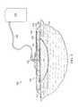
- FIG. 1is sectional view of an example embodiment of a negative-pressure therapy system that can provide negative-pressure therapy in accordance with this specification;
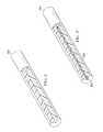
- FIG. 2is a perspective view, with a portion shown in cross-section, of an example embodiment of a fiber of the multi-function core of FIG. 1 ;
- FIG. 3is a perspective view, with a portion shown in cross-section, of an example embodiment of a dual-layer fiber of the multi-function core of FIG. 1 ;
- FIG. 4is a perspective view illustrating additional details of a woven layer of the multi-function core of FIG. 1 ;
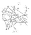
- FIG. 5is a plan view illustrating additional details of a non-woven layer of the multi-function core of FIG. 1 ;
- FIG. 6is a schematic sectional exploded view illustrating additional details that may be associated with an example embodiment of a multi-function core of the negative-pressure therapy system of FIG. 1 ;
- FIG. 7is a schematic representation of an example embodiment of a manufacturing process for producing the multi-function core of FIG. 6 .
- FIG. 1is a sectional view with a portion shown in elevation of an example embodiment of a negative-pressure therapy system 100 that can provide negative-pressure therapy in accordance with this specification.
- the negative-pressure therapy system 100may include a dressing 102 and a negative-pressure source 104 .
- a dressing 102may be fluidly coupled to a negative-pressure source 104 , as illustrated in FIG. 1 .
- the negative-pressure source 104may be fluidly coupled to the dressing 102 by a tube 106 and a connector 107 .
- a dressinggenerally includes a cover and a tissue interface.
- the dressing 102for example, includes a cover 108 , and a tissue interface 110 .
- the dressing 102may also include a fluid management core, such as a core 112 .
- components of the negative-pressure therapy system 100may be coupled directly or indirectly.
- the negative-pressure source 104may be directly coupled to the connector 107 and indirectly coupled to the dressing 102 through the connector 107 .
- Componentsmay be fluidly coupled to each other to provide a path for transferring fluids (i.e., liquid and/or gas) between the components.
- componentsmay be fluidly coupled through a tube.
- a tubeis an elongated, cylindrical structure with some flexibility, but the geometry and rigidity may vary.
- componentsmay additionally or alternatively be coupled by virtue of physical proximity, being integral to a single structure, or being formed from the same piece of material. Coupling may also include mechanical, thermal, electrical, or chemical coupling (such as a chemical bond) in some contexts.
- the tissue interface 110may be placed within, over, on, or otherwise proximate to a tissue site.
- the cover 108may be placed over the tissue interface 110 and sealed to tissue near the tissue site.
- the cover 108may be sealed to undamaged epidermis peripheral to a tissue site.
- the dressing 102can provide a sealed therapeutic environment proximate to a tissue site, substantially isolated from the external environment, and the negative-pressure source 104 can reduce the pressure in the sealed therapeutic environment. Negative pressure applied across the tissue site through the tissue interface 110 in the sealed therapeutic environment can induce macrostrain and microstrain in the tissue site, as well as remove exudates and other fluids from the tissue site, which can be collected in the dressing core 112 and disposed of properly.
- the fluid mechanics of using a negative-pressure source to reduce pressure in another component or location, such as within a sealed therapeutic environment,can be mathematically complex.
- the basic principles of fluid mechanics applicable to negative-pressure therapyare generally well-known to those skilled in the art, and the process of reducing pressure may be described illustratively herein as “delivering,” “distributing,” or “generating” negative pressure, for example.
- downstreamtypically implies a position in a fluid path relatively closer to a negative-pressure source
- upstreamimplies a position relatively further away from a negative-pressure source.
- fluid inletor “outlet” in such a frame of reference. This orientation is generally presumed for purposes of describing various features and components of negative-pressure therapy systems herein.
- the fluid pathmay also be reversed in some applications (such as by substituting a positive-pressure source for a negative-pressure source) and this descriptive convention should not be construed as a limiting convention.
- tissue sitein this context broadly refers to a wound or defect located on or within tissue, including but not limited to, bone tissue, adipose tissue, muscle tissue, neural tissue, dermal tissue, vascular tissue, connective tissue, cartilage, tendons, or ligaments.
- a woundmay include chronic, acute, traumatic, subacute, and dehisced wounds, partial-thickness burns, ulcers (such as diabetic, pressure, or venous insufficiency ulcers), flaps, and grafts, for example.
- tissue sitemay also refer to areas of any tissue that are not necessarily wounded or defective, but are instead areas in which it may be desirable to add or promote the growth of additional tissue. For example, negative pressure may be used in certain tissue areas to grow additional tissue that may be harvested and transplanted to another tissue location.
- Negative pressuregenerally refers to a pressure less than a local ambient pressure, such as the ambient pressure in a local environment external to a sealed therapeutic environment provided by the dressing 102 .
- the local ambient pressuremay also be the atmospheric pressure at which a tissue site is located.
- the pressuremay be less than a hydrostatic pressure associated with tissue at the tissue site. Unless otherwise indicated, values of pressure stated herein are gauge pressures.
- references to increases in negative pressuretypically refer to a decrease in absolute pressure, while decreases in negative pressure typically refer to an increase in absolute pressure.
- a negative-pressure sourcesuch as the negative-pressure source 104
- a negative-pressure sourcemay be housed within or used in conjunction with other components, such as sensors, processing units, alarm indicators, memory, databases, software, display devices, or user interfaces that further facilitate negative-pressure therapy.
- the pressureis generally a low vacuum, also commonly referred to as a rough vacuum, between ⁇ 5 mm Hg ( ⁇ 667 Pa) and ⁇ 500 mm Hg ( ⁇ 66.7 kPa).
- a rough vacuumbetween ⁇ 5 mm Hg ( ⁇ 667 Pa) and ⁇ 500 mm Hg ( ⁇ 66.7 kPa).
- Common therapeutic rangesare between ⁇ 75 mm Hg ( ⁇ 9.9 kPa) and ⁇ 300 mm Hg ( ⁇ 39.9 kPa).
- the tissue interface 110can be generally adapted to contact a tissue site.
- the tissue interface 110may be partially or fully in contact with the tissue site. If the tissue site is a wound, for example, the tissue interface 110 may partially or completely fill the wound, or may be placed over the wound.
- the tissue interface 110may take many forms, and may have many sizes, shapes, or thicknesses depending on a variety of factors, such as the type of treatment being implemented or the nature and size of a tissue site. For example, the size and shape of the tissue interface 110 may be adapted to the contours of deep and irregular shaped tissue sites.
- the tissue interface 110may be a manifold.
- a “manifold” in this contextgenerally includes any substance or structure providing a plurality of pathways adapted to collect or distribute fluid across a tissue site under negative pressure.
- a manifoldmay be adapted to receive negative pressure from a source and distribute the negative pressure through multiple apertures across a tissue site, which may have the effect of collecting fluid from across a tissue site and drawing the fluid toward the source.
- the fluid pathmay be reversed or a secondary fluid path may be provided to facilitate delivering fluid across a tissue site.
- the pathways of a manifoldmay be channels interconnected to improve distribution or collection of fluids across a tissue site.
- cellular foam, open-cell foam, reticulated foam, porous tissue collections, and other porous materialsuch as gauze or felted mat generally include pores, edges, and/or walls adapted to form interconnected fluid pathways.
- Liquids, gels, and other foamsmay also include or be cured to include apertures and flow channels.
- a manifoldmay be a porous foam material having interconnected cells or pores adapted to uniformly (or quasi-uniformly) distribute negative pressure to a tissue site.
- the foam materialmay be either hydrophobic or hydrophilic.
- a manifoldmay be an open-cell, reticulated polyurethane foam such as GranuFoam® dressing available from Kinetic Concepts, Inc. of San Antonio, Tex.
- the tissue interface 110may be made from a hydrophilic material
- the tissue interface 110may also wick fluid away from a tissue site, while continuing to distribute negative pressure to the tissue site.
- the wicking properties of the tissue interface 110may draw fluid away from a tissue site by capillary flow or other wicking mechanisms.
- An example of a hydrophilic foamis a polyvinyl alcohol, open-cell foam such as V.A.C. WhiteFoam® dressing available from Kinetic Concepts, Inc. of San Antonio, Tex.
- Other hydrophilic foamsmay include those made from polyether.
- Other foams that may exhibit hydrophilic characteristicsinclude hydrophobic foams that have been treated or coated to provide hydrophilicity.
- the tissue interface 110may further promote granulation at a tissue site when pressure within the sealed therapeutic environment is reduced.
- any or all of the surfaces of the tissue interface 110may have an uneven, coarse, or jagged profile that can induce microstrains and stresses at a tissue site if negative pressure is applied through the tissue interface 110 .
- the tissue interface 110may be constructed from bioresorbable materials. Suitable bioresorbable materials may include, without limitation, a polymeric blend of polylactic acid (PLA) and polyglycolic acid (PGA). The polymeric blend may also include without limitation polycarbonates, polyfumarates, and capralactones.
- the tissue interface 110may further serve as a scaffold for new cell-growth, or a scaffold material may be used in conjunction with the tissue interface 110 to promote cell-growth.
- a scaffoldis generally a substance or structure used to enhance or promote the growth of cells or formation of tissue, such as a three-dimensional porous structure that provides a template for cell growth.
- Illustrative examples of scaffold materialsinclude calcium phosphate, collagen, PLA/PGA, coral hydroxy apatites, carbonates, or processed allograft materials.
- a sealing membersuch as the cover 108
- the cover 108may provide a bacterial barrier and protection from physical trauma.
- the cover 108may also be constructed from a material that can reduce evaporative losses and provide a fluid seal between two components or two environments, such as between a therapeutic environment and a local external environment.
- the cover 108may be, for example, an elastomeric film or membrane that can provide a seal adequate to maintain a negative pressure at a tissue site for a given negative-pressure source.
- the cover 108may be a polymer drape, such as a polyurethane film, that is permeable to water vapor but impermeable to liquid. Such drapes typically have a thickness in the range of 25-50 microns. For permeable materials, the permeability generally should be low enough that a desired negative pressure may be maintained.
- An attachment devicemay be used to attach the cover 108 to an attachment surface, such as undamaged epidermis, a gasket, or another cover.
- the attachment devicemay take many forms.
- an attachment devicemay be a medically-acceptable, pressure-sensitive adhesive that extends about a periphery, a portion, or an entire sealing member.
- some or all of the cover 108may be coated with an acrylic adhesive having a coating weight between 25-65 g.s.m. Thicker adhesives, or combinations of adhesives, may be applied in some embodiments to improve the seal and reduce leaks.
- Other example embodiments of an attachment devicemay include a double-sided tape, paste, hydrocolloid, hydrogel, silicone gel, or organogel.
- Tissue sitesmay produce fluids that can be removed by negative pressure. Fluids removed from a tissue site can be collected for subsequent disposal or analysis.
- a canistermay be fluidly coupled to a dressing to collect fluids from a wound.
- Such canistersare readily available and can be relatively inexpensive. However, canisters can also be cumbersome and limit patient mobility. Some dressings can absorb fluids, which can enhance patient mobility, but manufacturing a dressing with adequate fluid capacity can be complex and expensive.
- a fluid management coresuch as the core 112 can reduce the cost and complexity of manufacturing a dressing with fluid storage capacity.
- a multi-function coremay include six or more layers that provide skin contact, fluid wicking, ion exchange, liquid absorbing, liquid blocking, and odor absorbing functions in a unitary apparatus.
- a dressingmay be manufactured by a process that produces each layer as a part and assembles the multi-function core in a process that reduces manufacturing time and costs.
- the core 112may be a multi-function core or fluid management apparatus having multiple layers that can be configured to accomplish different functions.
- the core 112may include six layers.
- the core 112may have a wound interface layer or contact layer 114 , a fluid dispersion layer or wicking layer 116 , an ion removal layer or ion exchange layer 118 , a liquid retention layer or absorbing layer 120 , a liquid obstruction layer or blocking layer 122 , and an odor removal layer or odor absorbing layer 124 .
- Each layermay be formed from a plurality of fibers disposed in a fibrous web.
- a fibrous webmay include a plurality of fibers positioned so that individual fibers overlap and are coupled to one another to form open spaces between adjacent fibers.
- the fibrous webmay be a woven or non-woven.
- the plurality of fibersmay be single-layer fibers.
- the plurality of fibersmay be dual-layer fibers.
- the fibers of a particular layermay be both single-layer and dual-layer fibers.
- the core 112may have a high moisture vapor transfer rate (MVTR) and gas permeability across the structure such that dry negative pressure, that is, air having little or no moisture content, may be manifolded across the entire area of the core 112 .
- MVTRmoisture vapor transfer rate
- the core 112may have an MVTR between about 250 g/m 2 /day and about 2000 g/m 2 /day when measured at 37° C. and 50%/relative humidity using the upright cup method. In some embodiments, the core 112 may have a gas permeability of oxygen of about 50 cm 3 /m 2 /day/MPa.
- FIG. 2is a partial sectional view of a single-layer fiber 200 , illustrating additional details that may be associated with some example embodiments.
- the single-layer fiber 200may have a diameter in the range of about 1 micron to about 50 microns.
- the single-layer fiber 200may be a fiber having a substantially homogenous composition.
- the single-layer fiber 200may be formed from a single material, such as polyurethane, polyester, acrylic, fluorocarbon, or silicone.
- the single-layer fiber 200may be associated with additional materials, such as activated carbon particles or superabsorbent polymer particles or fibers.
- the single-layer fiber 200may be formed from silicone and have activated carbon particles disposed within or on the silicone.
- the single-layer fiber 200may be formed by melt-blown fiber formation, melt-spinning fiber formation, wet-spinning fiber formation, or solution-based electro spinning.
- Melt blown fiber formationmay involve extruding melted polymers through a spin net or die to produce fibers. Hot air may be blown over the fibers to stretch and cool the fibers as the fibers pass out of the spin net or die.
- Melt spinningmay involve melting a polymer and squeezing the melted polymer through a spinneret to form a fiber.
- siliconemay be mixed with glycerol and deionized water to form a solution.
- the solutionmay be fed into an extruder spinning system to form fibers.
- Wet spinningmay involve dissolving the polymer to form a coagulating bath having a low pH. Liquid in the coagulating bath may be evaporated to form a fine fiber.
- siliconecan be processed by a cylinder spinning system to spin a thread that may be coagulated in a bath, air dried, and wound on a bobbin.
- Electrospinningmay subject a polymer solution to an electric field to induce the accumulation of a charge on the surface of a pendant drop.
- the charge accumulationgenerates a force that directly opposes the force produced by the surface tension of the drop that, above a critical value of electric field strength, can cause a charged jet to eject to form fine filaments.
- the filamentsmay then be cut into standardized lengths to form staple fibers.
- the staple fibersmay have a length between about 4 mm and about 6 mm.
- the staple fibersmay be twisted together and carded to form the single-layer fiber 200 .
- FIG. 3is a partial sectional view of a dual-layer fiber 300 , illustrating additional details that may be associated with some example embodiments.
- the dual-layer fiber 300may have an inner core 302 and an outer sheathing 304 .
- the inner core 302may be a fiber having a substantially homogenous composition.
- the inner core 302may be formed from a single material, such as polyurethane, polyester, acrylic, fluorocarbon, or silicone.
- the inner core 302may be associated with additional materials, such as activated carbon particles or antimicrobials.
- the inner core 302may be formed from silicone and have activated carbon particles disposed within or on the silicone.
- the inner core 302may be formed by melt-blown fiber formation, melt-spinning fiber formation, wet-spinning fiber formation, or solution-based electro spinning. In some embodiments, the inner core 302 may have a diameter in the range of about 0.75 microns to about 75 microns.
- the outer sheathing 304may be a coating of a material that is different than the material of the inner core 302 . In some embodiments, the outer sheathing 304 may be formed from a silicone gel or hydrophilic polyurethane. In some embodiments, the outer sheathing 304 may have a thickness between about 0 microns and about 12.5 microns. In some embodiments, the dual-layer fiber 300 may have an overall diameter between about 0.75 microns and about 100 microns.
- FIG. 4is a perspective view of a portion of a layer that may be associated with some embodiments of the core 112 .
- the layermay be the wicking layer 116 having a woven structure as illustrated in FIG. 4 .
- a wovengenerally refers to a fabric-like material formed by weaving, knitting, lace-making, felting, braiding, or plaiting fibers so that the fibers are interlaced.
- the wicking layer 116is illustrated in FIG. 4 , any or all of the contact layer 114 , the ion exchange layer 118 , and the absorbing layer 120 may also be formed as a woven analogous to the wicking layer 116 .
- the fibers of a woven layermay be single-layer fibers 200 .
- the fibers of a woven layermay be dual-layer fibers 300 .
- the wicking layer 116may be formed by weaving the single-layer fibers 200 to form a regular pattern of openings or mesh apertures 230 . As illustrated in FIG. 4 , the wicking layer 116 may comprise a first plurality of single-layer fibers 200 aligned substantially parallel to each other and a second plurality of single-layer fibers 201 also aligned substantially parallel to each other, wherein the fibers 200 are disposed adjacent to the fibers 201 at an angle.
- the fibers 200may be perpendicular to the fibers 201 .
- the fibers 200 and the fibers 201may overlap each other to form a weave or mesh having the plurality of apertures 230 .
- the fibers 200may intersect with the fibers 201 to form a plurality of intersections 236 .
- An intersection 236may be formed by overlapping fibers.
- the fibers 200 and the fibers 201may be woven together to form a network or a mesh.
- the first fibers 200 and the second fibersmay be separated from adjacent fibers 200 and fibers 201 , respectively, by a distance 232 and 234 , respectively, which may be between about 0.5 mm and about 5 mm. In other embodiments, the distance 232 and 234 may be between about 1.0 mm and about 2.5 mm. In some embodiments, the distance 232 and the distance 234 may be the substantially equal. In other embodiments, the distance 232 and the distance 234 may be different.
- the mesh apertures 230may have an average effective diameter of about 2 mm.
- An effective diameter of a non-circular areamay be a diameter of a circular area having the same surface area as the non-circular area.
- the surface area of a mesh aperture 230 where the distance 232 is 0.5 mm and the distance 234 is 0.5 mmmay be 0.25 mm 2 .
- the diameter of a circular area having a 0.25 mm 2 surface areais about 0.56 mm; consequently, the effective diameter of the exemplary mesh aperture 230 is about 0.56 mm.
- the effective diameter of the mesh aperture 230may be about 4.51 mm.
- each mesh aperture 230may have an area formed by the effective diameter of the mesh aperture 230 . In some embodiments, each mesh aperture 230 may be uniform in area. In other embodiments, each mesh aperture 230 may not be uniform in area. If the mesh apertures 230 are not uniform in area, the average of the areas of the mesh apertures 230 may be between about 0.2 mm 2 and about 20 mm 2 .
- Each of the contact layer 114 , the wicking layer 116 , the ion exchange layer 118 , the absorbing layer 120 , the blocking layer 122 , and the odor absorbing layer 124may have mesh apertures 230 between about 0.2 mm 2 and about 20 mm 2 .
- each of the single-layer fibers 200 , 201 of the wicking layer 116may have a diameter 228 . In other embodiments, the diameters of the single-layer fibers 200 , 201 may be different.
- the intersections 236may have a prominence 241 . In some embodiments, the prominence 241 at the intersections 236 may be equal to the diameter 228 of the single-layer fibers 200 , 201 . In some embodiments, the prominence 241 may be reduced by compressing the wicking layer 116 following formation of the wicking layer 116 .
- the prominences 241may also be reduced by passing the wicking layer 116 through a calender, which may apply pressure to the wicking layer 116 to smooth out the wicking layer 116 .
- a calenderwhich may apply pressure to the wicking layer 116 to smooth out the wicking layer 116 .
- Each of the contact layer 114 , the wicking layer 116 , the ion exchange layer 118 , the absorbing layer 120 , the blocking layer 122 , and the odor absorbing layer 124may have prominences 241 .
- the wicking layer 116may have a thickness 224 . In some embodiments, the thickness 224 may be the combined thickness of the diameters 228 of the single-layer fibers 200 , 201 .
- FIG. 5is a schematic view of a portion of a non-woven layer, such as the wicking layer 116 , illustrating additional details that may be associated with other example embodiments of the negative-pressure therapy system 100 .
- a non-wovenmay be a layer of fabric-like material made from long fibers that may be bonded together by chemical, mechanical, heat, or solvent treatment. Non-wovens may be melt blown, air laid, thermo bonded, and spun bonded, for example.
- Each of the contact layer 114 , the ion exchange layer 118 , the absorbing layer 120 , the blocking layer 122 , and the odor-absorbing layer 124may be formed as a non-woven as described with respect to the wicking layer 116 herein.
- the non-woven wicking layer 116may operate similarly or analogously to the woven wicking layer 116 . Similar elements may have similar reference numbers that are indexed to 300.
- a plurality of dual-layer fibers 300may be formed into the non-woven wicking layer 116 .
- the dual-layer fibers 300may be dispersed on a conveyor belt, and spread in a uniform web by a wetlaid, an airlaid, or a carding/crosslapping process.
- the dual-layer fibers 300may be bonded thermally or by using a resin to form the mesh of the wicking layer 116 .
- the dual-layer fibers 300may overlap and form intersections 336 where the dual-layer fibers 300 overlap with other dual-layer fibers 300 .
- the overlapping dual-layer fibers 300 of the wicking layer 116may also form openings, such as mesh apertures 330 .
- the mesh apertures 330may not be uniform in shape.
- the mesh apertures 330 of the wicking layer 116may have an average effective diameter between about 1 mm and about 5 mm. If the mesh apertures 330 are not uniform in size the average of the effective diameters of each of the mesh apertures 330 may be between about 1 mm and about 5 mm.
- the wicking layer 116may also be formed in a spunlaid process. Spunlaid non-wovens may be made in a continuous process.
- the dual-layer fibers 300may be dispersed into a web by physical deflectors or with air streams as the dual-layer fibers 300 are produced without further cutting the dual-layer fibers 300 .
- a thickness of the non-woven wicking layer 116 , the dual-layer fibers 300 , a diameter of the dual-layer fibers 300 , the mesh apertures 330 , and the intersections 336may be similar to and operate as described above with respect to the woven wicking layer 116 , the thickness 224 of the wicking layer 116 , the single-layer fibers 200 , 201 , the diameter 228 , the mesh apertures 230 , and the intersections 236 , respectively.
- FIG. 6is a schematic sectional exploded view illustrating additional details that may be associated with an example embodiment of the multi-function core 112 .
- the contact layer 114 , the wicking layer 116 , the ion exchange layer 118 , the absorbent layer 120 , the blocking layer 122 , the odor-absorbing layer 124 , and the rigid layer 126may be coextensive with one another.
- one or more of the contact layer 114 , the wicking layer 116 , the ion exchange layer 118 , the absorbent layer 120 , the blocking layer 122 , the odor-absorbing layer 124 , and the rigid layer 126may be coextensive with one another.
- the contact layer 114 , the wicking layer 116 , the ion exchange layer 118 , the absorbent layer 120 , the blocking layer 122 , the odor-absorbing layer 124 , and the rigid layer 126may not be coextensive with one another. In some embodiments, one or more of the contact layer 114 , the wicking layer 116 , the ion exchange layer 118 , the absorbent layer 120 , the blocking layer 122 , the odor-absorbing layer 124 , and the rigid layer 126 may draw negative-pressure through the respective layer.
- one or more of the contact layer 114 , the wicking layer 116 , the ion exchange layer 118 , the absorbent layer 120 , the odor-absorbing layer 124 , and the rigid layer 126may be liquid permeable.
- the contact layer 114may be formed from a plurality of dual-layer fibers 300 formed into a woven or non-woven layer of material. In some embodiments, the contact layer 114 may have a thickness between about 0.5 millimeters (mm) and about 2 mm.
- the dual-layer fibers 300may have the inner core 302 formed from a hydrophobic polyurethane and the outer sheathing 304 formed from a silicone gel.
- the inner core 302may be a hydrophobic polyurethane core and the outer sheathing 304 may be a hydrophilic polyurethane.
- the hydrophilic polyurethane of the outer sheathing 304may be a gel.
- an antimicrobialsuch as silver
- an antimicrobialsuch as iodine
- the antimicrobialmay have a time-release property.
- the outer sheathing 304may be formed from collagen.
- the contact layer 114may seal to epidermis surrounding a tissue site.
- the contact layer 114may be tacky to assist in forming a seal.
- the contact layer 114may have a tackiness or peel adhesion of about 0.2 N/cm on stainless steel substrate at 23° C. at 50% relative humidity based on the American Society for Testing and Materials (“ASTM”) standard ASTM D3330.
- ASTMAmerican Society for Testing and Materials
- the dual-layer fibers 300may have a tensile strength of about 40 Newtons (N) per 5 cm length in the direction of the applied force with a tolerance of about +/ ⁇ 15%, and the contact layer 114 may permit fluid flow at about 0.83 cubic centimeters/hour.
- the wicking layer 116may be formed from a plurality of single-layer fibers 200 formed into a woven or a non-woven. In some embodiments, the wicking layer 116 may have a thickness between about 1 mm and about 4 mm. In some embodiments, the single-layer fibers 200 may be formed from a hydrophilic polymer such as polyurethane, polyester, or acrylic. In other embodiments, the wicking layer 116 may be formed from dual-layer fibers 300 . If the wicking layer 116 is formed from dual-layer fibers 300 , the inner core 302 may be formed from hydrophobic polyurethane, and the outer sheathing 304 may be formed from hydrophilic polyurethane.
- the hydrophobic polyurethane of the inner core 302may provide more strength than the single-layer fiber 200 formed from the hydrophilic polyurethane alone.
- polyurethanemay have a strength inversely proportional to its volumetric water content.
- the inner core 302 of the dual-layer fiber 300 of the wicking layer 116may resist water absorption, thereby increasing the strength of the dual-layer fiber 300 .
- the wicking layer 116 formed as a non-woven having the dual-layer fibers 300may have a tensile strength of about 40 Newtons (N) per 5 cm length in the direction of the applied force with a tolerance of about +/ ⁇ 15%.
- the wicking layer 116may encourage fluid to spread at an angle to the direction of fluid flow. For example, if a negative-pressure source is drawing fluid through the wicking layer 116 parallel to the thickness of the wicking layer 116 , the wicking layer 116 may encourage fluid to spread perpendicular to the thickness of the wicking layer 116 . In some embodiments, the wicking layer 116 may permit fluid flow at about 0.83 cubic centimeters/hour or greater.
- the ion exchange layer 118may be formed from a plurality of dual-layer fibers 300 .
- the ion exchange layer 118may have a thickness in the range of 0.5 mm and about 2 mm, a flow rate of about 0.83 cubic centimeters/hour, and the dual-layer fibers 300 may have a tensile strength of about 40 Newtons (N) per 5 cm length in the direction of the applied force with a tolerance of about +/ ⁇ 15%.
- the dual-layer fibers 300 of the ion exchange layer 118may have an inner core 302 formed from a hydrophobic polymer, such as a hydrophobic polyurethane and an outer sheathing 304 formed from a hydrophilic polymer, such as a hydrophilic polyurethane.
- Ion exchange mediaIEM
- IEMmay be disposed in the outer sheathing 304 .
- IEMmay exchange both hydrogen and hydroxyl ions for cationic and anionic salt ions found in wound fluids, such as sodium, chloride, and calcium.
- the ion exchange layer 118may be formed from a single-layer fiber 200 formed from a hydrophilic polymer having activated carbon particles or fibers for ion exchange functionality.
- IEMmay be adapted to provide an exchange of ions between two electrolytes, or between an electrolyte solution and a complex.
- An electrolytemay be a compound that ionizes when dissolved in a suitable ionizing solvent, such as water.
- An electrolyte solutionmay contain a dissolved salt, such as NaCl.
- a complexmay be an atom or ion having a surrounding array of bound molecules or anions known as ligands or complexing agents.
- IEMreplaces cations and anions in an electrolyte or an electrolyte solution as the electrolyte or electrolyte solution interacts with the IEM. Cations are ions having a net positive charge, for example, Na+.
- Cationsmay be replaced in the electrolyte or electrolyte solution with hydrogen (H+) ions of the IEM.
- Anionsare ions having a net negative charge, for example, Cl ⁇ .
- Anionsmay be replaced in the electrolyte or electrolyte solution with hydroxyl (OH ⁇ ) ions of the IEM.
- the H+ and OH ⁇ ionsmay combine in the electrolyte or electrolyte solution to form water.
- the IEMis typically in the form of porous beads that are formed from crosslinked polymers, such as polystyrene, that are doped or grafted with acidic polymers.
- An example of an acidic polymermay include poly(2-acrylamido-2-methyl-1-propanesulfonic acid) or polyAMPS.
- the polyAMPSexchange positively charged salt ions for H+.
- Another example of an acidic polymermay include poly(acrylamido-N-propyltrimethylammonium chloride) or polyAPTAC.
- the polyAPTACexchange negatively charged salt ions for OH ⁇ .
- the IEMmay include a mixture of cation absorbing media and anion absorbing media to form a mixed bed media that simultaneously absorbs both anions and cations.
- Non-limiting examples of the mixed bed mediainclude AmberliteTM IRN150 and TMD-8.
- the IEMmay be formed from ion exchange resins, zeolites, montmorillonite, bentonites, clay, or soil humus, for example.
- Ion exchange resinsalso known as ion exchange polymers, are insoluble matrices normally in the form of small beads fabricated from an organic polymer substrate. Ion exchange resins may have pores on the surface that trap and release ions. Ion exchange resins can include crosslinked polystyrene, for example.
- Zeolitesare microporous, aluminosilicate minerals. Zeolites have a porous structure that allow cations, such as Na + , K + , Ca 2+ , and Mg 2+ , for example, to be accommodated by the zeolite. Common zeolites include analcime, chabazite, clinoptilolite, heulandite, natrolite, phillipsite, and stilbite, for example. In addition to the above materials, other ion exchange media include activated charcoal, both particulate and in the form of fabrics or non-wovens, for example, and Zorflex®, also known as Chemviron Carbon. Chemviron Carbon may also be known as 100% activated carbon.
- a fluid having 0.154 moles/liter of NaClwas passed through the ion exchange layer 118 .
- the ion exchange layer 118removed Na+ and CL ⁇ ions at a rate of about 0.0026 moles per hour.
- the ion exchange layer 118may have a similar or greater ion removal rate.
- the absorbing layer 120may be formed from a plurality of dual-layer fibers 300 .
- the dual-layer fibers 300 of the absorbing layer 120may have the inner core 302 formed from a superabsorbent polymer, such as polyacrylates, polyacrylics, or carboxymethyl cellulose.
- the outer sheathing 304may be hydrophilic.
- the absorbing layer 120may be formed from single-layer fibers 200 having an elastic polymer such as an elastane polyurethane with superabsorbent particles disposed therein.
- fibers of the absorbing layer 120may be either woven or non-woven.
- the absorbing layer 120may have a thickness in the range of about 1 mm to about 4 mm.
- the single layer fibers 200 and the dual-layer fibers 300may have a tensile strength of about 40 Newtons (N) per 5 cm length in the direction of the applied force with a tolerance of about +/ ⁇ 15%.
- the absorbing layer 120may permit a flow rate of about 0.83 cubic centimeters/hour.
- the superabsorbent or superabsorbent particlesmay be formed from a superabsorbent polymer (SAP).
- SAPscan absorb and retain large quantities of liquid, and in particular water. For example, some SAPs may be able to absorb about 500 times its own weight in water, or about 30 to 60 times its own volume in water. The ability of an SAP to absorb water may be based in part on the ionic concentration of the fluid being absorbed.
- SAPsmay be of the type often referred to as “hydrogels,” “super-absorbents,” or “hydrocolloids.” SAPs may be formed into fibers or spheres. Spaces or voids between the fibers or spheres may allow a reduced pressure to be transferred within and through the absorbing layer 120 .
- SAPsmay be formed in several ways, for example, by gel polymerization, solution polymerization, or suspension polymerization.
- Gel polymerizationmay involve blending of acrylic acid, water, cross-linking agents, and ultraviolet (UV) initiator chemicals. The blended mixture may be placed into a reactor where the mixture is exposed to UV light to cause crosslinking reactions that form an SAP. The mixture may be dried and shredded before subsequent packaging and/or distribution.
- Solution polymerizationmay involve a water-based monomer solution that produces a mass of reactant polymerized gel. The monomer solution may undergo an exothermic reaction that drives the crosslinking of the monomers. Following the crosslinking process, the reactant polymer gel may be chopped, dried, and ground to its final granule size.
- Suspension polymerizationmay involve a water-based reactant suspended in a hydrocarbon-based solvent. However, the suspension polymerization process must be tightly controlled and is not often used.
- SAPsabsorb liquids by bonding with water molecules through hydrogen bonding. Hydrogen bonding involves the interaction of a polar hydrogen atom with an electronegative atom. As a result, SAPs absorb water based on the ability of the hydrogen atoms in each water molecule to bond with the hydrophilic polymers of the SAP having electronegative ionic components.
- High-absorbing SAPsare formed from ionic crosslinked hydrophilic polymers such as acrylics and acrylamides in the form of salts or free acids.
- the absorbing layer 120may use ionic based SAPs formed from ester salts such as sodium and potassium of acrylic, acrylate, and methacrylate copolymers. In some embodiments, the absorbing layer 120 may retain liquid at a rate greater than about 0.83 cubic centimeters/hour.
- the blocking layer 122may be formed from a plurality of single-layer fibers 200 formed from a highly hydrophobic polymer such as polyurethane or fluorocarbon. Hydrophobicity may be measured by a surface energy of the material, where a lower surface energy corresponds to a higher hydrophobicity. In some embodiments, the hydrophobic polymer of the single-layer fibers 200 of the blocking layer 122 may be about 25 milliNewtons/meter or less. Generally, the blocking layer 122 may prevent liquid flow through the blocking layer 122 by creating a pressure barrier for liquid movement.
- the hydrophobic material of the blocking layer 122may prevent liquid passage where the pressure drawing liquid into and through the blocking layer 122 is less than a water breakthrough pressure of the blocking layer 122 .
- the water breakthrough pressure of a materialincreases as the hydrophobicity of the material increases.
- the blocking layer 122may have a water breakthrough pressure greater than about 125 mm Hg negative pressure.
- the blocking layer 122may have a non-woven structure to provide for the manifolding of air and negative pressure over the entire area of the structure.
- a non-woven structuremay have a porosity or density that permits an air flow for a given pressure; similar to a woven structure.
- a non-wovenmay also be referred to as an open non-woven.
- the porositymay be measured by the amount of free volume of the non-woven, that is how much of the structure is not occupied by fibers.
- the blocking layer 122may have a free volume of about 85% to about 98%.
- the blocking layer 122may permit about 0.2 to about 1.0 liters/m 2 /minute/Pa of air flow through the blocking layer 122 .
- the blocking layer 122may have a thickness in the range of 0.2 mm and about 0.5 mm, and the single-layer fibers 200 may have a tensile strength of about 40 Newtons (N) per 5 cm length in the direction of the applied force with a tolerance of about +/ ⁇ 15%.
- the odor-absorbing layer 124may be formed from a plurality of single-layer fibers 200 formed from a highly gas permeable polymer such as a polyurethane or a silicone that contains a dispersion of activated carbon particles.
- the odor-absorbing layer 124may also have a non-woven structure to provide for the manifolding of air and negative pressure over the entire area of the structure.
- the odor-absorbing layer 124may have a free volume of about 85% to about 98%.
- the odor-absorbing layer 124may permit about 0.2 to about 1.0 liters/m 2 /minute/Pa of air flow.
- the odor absorbing layer 124may have a thickness in the range of about 0.2 mm and about 1 mm.
- the single-layer fibers 200may have a tensile strength of about 40 Newtons (N) per 5 cm length in the direction of the applied force with a tolerance of about +/ ⁇ 15%.
- the core 112may also have a rigid layer 126 .
- the rigid layer 126may be a plurality of single-layer fibers 200 formed from polyurethane or a high hardness polymer. Generally a high hardness polymer has a hardness rating greater than or equal to about 70 Shore A. In some embodiments, the high hardness polymer may have a hardness rating between about 75 Shore A and about 85 Shore A. In some embodiments, the rigid layer 126 may have a thickness in the range of about 1 mm to about 4 mm. The rigid layer 126 may be disposed adjacent to the contact layer 114 or the odor absorbing layer 124 .
- the rigid layer 126may resist rucking, folding, or wrinkling of the core 112 . In some embodiments, the rigid layer 126 may increase rigidity between about 25% and about 40% over the core 112 without the rigid layer 126 . In some embodiments, the single-layer fibers 200 may have a tensile strength of about 40 Newtons (N) per 5 cm length in the direction of the applied force with a tolerance of about +/ ⁇ 15%.
- the contact layer 114may form a base of the core 112 , and the wicking layer 116 may be stacked adjacent to the contact layer 114 .
- the ion exchange layer 118may be stacked adjacent to the wicking layer 116
- the absorbing layer 120may be stacked adjacent to the ion exchange layer 118 .
- the blocking layer 122may be stacked adjacent to the absorbing layer 120
- the odor-absorbing layer 124may be placed adjacent to the blocking layer 122 to cap the core 112 .
- the layersmay be coupled to each other.
- the wicking layer 116may be coupled to the contact layer 114 by adhering, welding, or stitching.
- Each subsequent layermay be coupled in a similar manner to form the core 112 .
- each layerwill extend the full length and width of the core 112 so that a surface area of each layer is substantially the same.
- the core 112may be positioned adjacent to the manifold 110 , and the cover 108 may be placed over the core 112 and the manifold 110 to form a sealed therapeutic environment or a sealed space.
- the negative-pressure source 104may be fluidly coupled to the sealed space and operated to draw fluid from the tissue site.
- the contact layer 114may be in contact with the manifold 110 . In other embodiments, the contact layer 114 may be in direct contact with the tissue site or skin adjacent to the tissue site. The contact layer 114 may function to decrease irritation of the skin in contact with the core 112 .
- fluidmay be drawn through the contact layer 114 and into the wicking layer 116 .
- the wicking layer 116may function to aid in the distribution of fluid across the core 112 .
- the wicking layer 116may provide a pathway for fluid to move around the blockage and further into the core 112 .
- the hydrophilic properties of the single-layer fibers 200 of the wicking layer 116 , or the hydrophilic properties of the outer sheathing 304 of the dual-layer fibers 300 of the wicking layer 116encourage fluid movement through the wicking layer 116 .
- Fluidmay be drawn from the wicking layer 116 into the ion exchange layer 118 .
- salts in the fluidsmay be removed, decreasing the ionic concentration of the fluids.
- Fluidsmay be drawn from the ion exchange layer 118 into the absorbing layer 120 , where the fluids may be stored in the superabsorbent polymers of the absorbing layer 120 .
- the combination of the ion exchange layer 118 and the absorbing layer 120may increase the storage capacity of the core 112 over a core without the ion exchange layer 118 .
- the blocking layer 122may operate to prevent any liquids not trapped by the absorbing layer 120 from moving beyond the blocking layer 122 and out of the core 112 , thereby limiting the risk of damage to the negative-pressure source 104 .
- the hydrophobic properties of the single-layer fibers 200 of the blocking layer 122discourage liquid from moving into and through the blocking layer 122 .
- fluidsmostly gas, may be drawn through the odor absorbing layer 124 , where foul odors that may be traveling with the fluids can be absorbed.
- FIG. 7is a schematic diagram, illustrating a manufacturing system 500 for the core 112 that may be associated with some embodiments.
- the manufacturing system 500may include a plurality of work stations.
- the manufacturing system 500may have six work stations: a first work station 502 , a second work station 504 , a third work station 506 , a fourth work station 508 , a fifth work station 510 , and a sixth work station 512 .
- Each work stationmay be configured to form a separate layer of the core 112 .
- the first work station 502may be configured to form the contact layer 114
- the second work station 504may be configured to form the wicking layer 116
- the third work station 506may be configured to form the ion exchange layer 118
- the fourth work station 508may be configured to form the absorbing layer 120
- the fifth work station 510may be configured to form the blocking layer 122
- the sixth work station 512may be configured to form the odor absorbing layer 124 .
- each work station 502 - 512may form the fibers of the particular layer manufactured by that work station. In some embodiments each work station 502 - 512 may weave or position the fibers to form the material of the particular layer manufactured by that work station. In some embodiments, each work station 502 - 512 may both form the fibers of the particular layer and then engage in a process to form the fibers into a particular layer. The layers may then be fed from the work stations 502 - 512 to an assembly station 514 . The assembly station 514 may stack the layers and couple the layers to each other to form a multi-function sheet.
- the multi-function sheetmay be subdivided into smaller portions, such as individual cores 112 , for use with the negative-pressure therapy system 100 .
- the multi-function sheetmay be cut into cores 112 of varying sizes for varying tissue site sizes.
- more or fewer work stationsmay be used with the manufacturing system 500 to create alternative cores having more or fewer functions.
- the manufacturing system 500may include a seventh work station 516 configured to manufacture the rigid layer 126 .
- the third work station 506 or the sixth work station 512may be turned off or removed from the manufacturing system 500 entirely.
- the core 112simplifies dressing assembly as all of the characteristics of a wicking and absorbing core can be provided ready for placement at a tissue site by a clinician or user. A user may only be required to locate the core 112 at the tissue site and attach a cover over the core 112 .
- the core 112may also resist rucking and the formation of ridges that can result in blisters under the dressing during use.
- the core 112is highly configurable during manufacturing, allowing the addition or subtraction of layers and materials to accomplish different functions. For example, antimicrobial agents may be added to the contact layer 114 to aid fighting infection. Similarly, collagen may be added to the contact layer 114 to aid in regulation of matrix metalloproteinase.
Landscapes
- Health & Medical Sciences (AREA)
- Engineering & Computer Science (AREA)
- Veterinary Medicine (AREA)
- Public Health (AREA)
- General Health & Medical Sciences (AREA)
- Animal Behavior & Ethology (AREA)
- Life Sciences & Earth Sciences (AREA)
- Heart & Thoracic Surgery (AREA)
- Chemical & Material Sciences (AREA)
- Hematology (AREA)
- Biomedical Technology (AREA)
- Vascular Medicine (AREA)
- Materials Engineering (AREA)
- Epidemiology (AREA)
- Manufacturing & Machinery (AREA)
- Anesthesiology (AREA)
- Dispersion Chemistry (AREA)
- Chemical Kinetics & Catalysis (AREA)
- Automation & Control Theory (AREA)
- General Physics & Mathematics (AREA)
- General Engineering & Computer Science (AREA)
- Physics & Mathematics (AREA)
- Quality & Reliability (AREA)
- Inorganic Chemistry (AREA)
- Media Introduction/Drainage Providing Device (AREA)
- Materials For Medical Uses (AREA)
- Medicinal Chemistry (AREA)
- External Artificial Organs (AREA)
Abstract
Description
Claims (34)
Priority Applications (2)
| Application Number | Priority Date | Filing Date | Title |
|---|---|---|---|
| US14/869,731US10485891B2 (en) | 2014-10-06 | 2015-09-29 | Multi-function dressing structure for negative-pressure therapy |
| US16/565,071US20200000955A1 (en) | 2014-10-06 | 2019-09-09 | Multi-function dressing structure for negative-pressure therapy |
Applications Claiming Priority (3)
| Application Number | Priority Date | Filing Date | Title |
|---|---|---|---|
| US201462060098P | 2014-10-06 | 2014-10-06 | |
| US201462096669P | 2014-12-24 | 2014-12-24 | |
| US14/869,731US10485891B2 (en) | 2014-10-06 | 2015-09-29 | Multi-function dressing structure for negative-pressure therapy |
Related Child Applications (1)
| Application Number | Title | Priority Date | Filing Date |
|---|---|---|---|
| US16/565,071DivisionUS20200000955A1 (en) | 2014-10-06 | 2019-09-09 | Multi-function dressing structure for negative-pressure therapy |
Publications (2)
| Publication Number | Publication Date |
|---|---|
| US20160095754A1 US20160095754A1 (en) | 2016-04-07 |
| US10485891B2true US10485891B2 (en) | 2019-11-26 |
Family
ID=54289140
Family Applications (4)
| Application Number | Title | Priority Date | Filing Date |
|---|---|---|---|
| US14/869,731Active2037-11-14US10485891B2 (en) | 2014-10-06 | 2015-09-29 | Multi-function dressing structure for negative-pressure therapy |
| US14/869,649Active2037-02-17US10245346B2 (en) | 2014-10-06 | 2015-09-29 | Ion exchange absorbent systems, apparatuses, and methods |
| US16/263,178Active2036-12-12US11207442B2 (en) | 2014-10-06 | 2019-01-31 | Ion exchange absorbent systems, apparatuses, and methods |
| US16/565,071AbandonedUS20200000955A1 (en) | 2014-10-06 | 2019-09-09 | Multi-function dressing structure for negative-pressure therapy |
Family Applications After (3)
| Application Number | Title | Priority Date | Filing Date |
|---|---|---|---|
| US14/869,649Active2037-02-17US10245346B2 (en) | 2014-10-06 | 2015-09-29 | Ion exchange absorbent systems, apparatuses, and methods |
| US16/263,178Active2036-12-12US11207442B2 (en) | 2014-10-06 | 2019-01-31 | Ion exchange absorbent systems, apparatuses, and methods |
| US16/565,071AbandonedUS20200000955A1 (en) | 2014-10-06 | 2019-09-09 | Multi-function dressing structure for negative-pressure therapy |
Country Status (6)
| Country | Link |
|---|---|
| US (4) | US10485891B2 (en) |
| EP (5) | EP3964185A1 (en) |
| JP (2) | JP6802155B2 (en) |
| AU (3) | AU2015328546B2 (en) |
| CA (2) | CA2963263A1 (en) |
| WO (2) | WO2016057271A1 (en) |
Cited By (20)
| Publication number | Priority date | Publication date | Assignee | Title |
|---|---|---|---|---|
| US11116884B2 (en) | 2010-12-08 | 2021-09-14 | Convatec Technologies Inc. | Integrated system for assessing wound exudates |
| US11135315B2 (en) | 2010-11-30 | 2021-10-05 | Convatec Technologies Inc. | Composition for detecting biofilms on viable tissues |
| US11241339B2 (en) | 2011-11-29 | 2022-02-08 | Convatec Inc. | Perforated binder for laminated wound dressing |
| US11241525B2 (en) | 2010-12-08 | 2022-02-08 | Convatec Technologies Inc. | Wound exudate monitor accessory |
| US20220062061A1 (en)* | 2019-01-02 | 2022-03-03 | T.J.Smith And Nephew,Limited | Negative pressure wound therapy apparatus |
| US11266774B2 (en) | 2016-07-08 | 2022-03-08 | Convatec Technologies Inc. | Fluid collection apparatus |
| US11286601B2 (en) | 2012-12-20 | 2022-03-29 | Convatec Technologies, Inc. | Processing of chemically modified cellulosic fibres |
| US11331221B2 (en) | 2019-12-27 | 2022-05-17 | Convatec Limited | Negative pressure wound dressing |
| US11452808B2 (en) | 2016-07-08 | 2022-09-27 | Convatec Technologies Inc. | Fluid flow sensing |
| US11458044B2 (en) | 2008-09-29 | 2022-10-04 | Convatec Technologies Inc. | Wound dressing |
| US11583430B2 (en) | 2011-09-02 | 2023-02-21 | Convatec Ltd. | Skin contact material |
| US11596554B2 (en) | 2016-07-08 | 2023-03-07 | Convatec Technologies Inc. | Flexible negative pressure system |
| US11628093B2 (en) | 2008-05-08 | 2023-04-18 | Convatec Technologies, Inc. | Wound dressing |
| US11723808B2 (en) | 2016-03-30 | 2023-08-15 | Convatec Technologies Inc. | Detecting microbial infections in wounds |
| US11740241B2 (en) | 2016-03-30 | 2023-08-29 | Synovo Gmbh | Construct including an anchor, an enzyme recognition site and an indicator region for detecting microbial infection in wounds |
| US11771819B2 (en) | 2019-12-27 | 2023-10-03 | Convatec Limited | Low profile filter devices suitable for use in negative pressure wound therapy systems |
| US12076215B2 (en) | 2019-06-03 | 2024-09-03 | Convatec Limited | Methods and devices to disrupt and contain pathogens |
| US12121645B2 (en) | 2010-12-08 | 2024-10-22 | Convatec Technologies Inc. | Method and system for removing exudates from a wound site |
| US12161792B2 (en) | 2017-11-16 | 2024-12-10 | Convatec Limited | Fluid collection apparatus |
| US12290655B2 (en) | 2015-10-21 | 2025-05-06 | Convatec Limited | Wound dressing |
Families Citing this family (42)
| Publication number | Priority date | Publication date | Assignee | Title |
|---|---|---|---|---|
| WO2013066426A2 (en) | 2011-06-24 | 2013-05-10 | Kci Licensing, Inc. | Reduced-pressure dressings employing tissue-fixation elements |
| WO2015172111A1 (en) | 2014-05-09 | 2015-11-12 | Kci Licensing, Inc. | Disruptive dressing for use with negative pressure and fluid instillation |
| WO2015172108A1 (en) | 2014-05-09 | 2015-11-12 | Kci Licensing, Inc. | Dressing with contracting layer for linear tissue sites |
| US10898217B2 (en) | 2014-05-09 | 2021-01-26 | Kci Licensing, Inc. | Dressing providing apertures with multiple orifice sizes for negative-pressure therapy |
| DK3288508T3 (en) | 2015-04-27 | 2020-03-09 | Smith & Nephew | REDUCED PRESSURE DEVICES |
| BR112017023392A2 (en) | 2015-04-28 | 2018-07-17 | Convatec Technologies Inc | antibacterial nanofibers |
| EP3426206B1 (en) | 2016-03-07 | 2023-05-10 | Smith & Nephew plc | Wound treatment apparatuses and methods with negative pressure source integrated into wound dressing |
| CA3022184A1 (en) | 2016-04-26 | 2017-11-02 | Smith & Nephew Plc | Wound dressings and methods of use with integrated negative pressure source having a fluid ingress inhibition component |
| CA3038206A1 (en) | 2016-05-03 | 2017-11-09 | Smith & Nephew Plc | Optimizing power transfer to negative pressure sources in negative pressure therapy systems |
| WO2017191158A1 (en) | 2016-05-03 | 2017-11-09 | Smith & Nephew Plc | Systems and methods for driving negative pressure sources in negative pressure therapy systems |
| US11096831B2 (en) | 2016-05-03 | 2021-08-24 | Smith & Nephew Plc | Negative pressure wound therapy device activation and control |
| WO2018037075A1 (en) | 2016-08-25 | 2018-03-01 | Smith & Nephew Plc | Absorbent negative pressure wound therapy dressing |
| EP3519001B1 (en) | 2016-09-30 | 2025-05-21 | Smith & Nephew plc | Negative pressure wound treatment apparatuses and methods with integrated electronics |
| EP3551244A1 (en) | 2016-12-12 | 2019-10-16 | Smith & Nephew PLC | Pressure wound therapy status indication via external device |
| AU2018206475B2 (en)* | 2017-01-06 | 2023-09-28 | GeoRoc International, Inc. | Integrated ion-exchange disposal and treatment system |
| EP3592312B1 (en) | 2017-03-08 | 2024-01-10 | Smith & Nephew plc | Negative pressure wound therapy device control in presence of fault condition |
| JP7121050B2 (en) | 2017-05-09 | 2022-08-17 | スミス アンド ネフュー ピーエルシー | Redundant control of negative pressure wound therapy systems |
| AU2018282188A1 (en)* | 2017-06-07 | 2019-12-19 | 3M Innovative Properties Company | Tissue contact interface |
| WO2018226707A1 (en) | 2017-06-07 | 2018-12-13 | Kci Licensing, Inc. | Composite dressings for improved granulation reduced maceration with negative-pressure treatment |
| WO2018226650A1 (en) | 2017-06-07 | 2018-12-13 | Kci Licensing, Inc. | Systems, apparatuses, and methods for negative-pressure treatment with reduced tissue in-growth |
| AU2018282159A1 (en) | 2017-06-07 | 2019-12-19 | 3M Innovative Properties Company | Composite dressings for improved granulation and reduced maceration with negative-pressure treatment |
| WO2018226691A1 (en) | 2017-06-07 | 2018-12-13 | Kci Licensing, Inc. | Methods for manufacturing and assembling dual material tissue interface for negative-pressure therapy |
| WO2018226744A1 (en) | 2017-06-07 | 2018-12-13 | Kci Licensing, Inc. | Peel and place dressing for negative -pressure treatment |
| JP7204685B2 (en) | 2017-06-07 | 2023-01-16 | スリーエム イノベイティブ プロパティズ カンパニー | A composite dressing that promotes granulation formation and reduces maceration in negative pressure therapy |
| CN111031976A (en)* | 2017-06-12 | 2020-04-17 | 凯希特许有限公司 | Fabric wound filler |
| CN110753531B (en)* | 2017-06-30 | 2022-04-12 | T.J.史密夫及内修有限公司 | Spacer layer for wound dressing |
| CA3074780A1 (en) | 2017-09-13 | 2019-03-21 | Smith & Nephew Plc | Negative pressure wound treatment apparatuses and methods with integrated electronics |
| GB201718070D0 (en) | 2017-11-01 | 2017-12-13 | Smith & Nephew | Negative pressure wound treatment apparatuses and methods with integrated electronics |
| GB201718072D0 (en) | 2017-11-01 | 2017-12-13 | Smith & Nephew | Negative pressure wound treatment apparatuses and methods with integrated electronics |
| US11497653B2 (en) | 2017-11-01 | 2022-11-15 | Smith & Nephew Plc | Negative pressure wound treatment apparatuses and methods with integrated electronics |
| GB201718054D0 (en) | 2017-11-01 | 2017-12-13 | Smith & Nephew | Sterilization of integrated negative pressure wound treatment apparatuses and sterilization methods |
| US10624794B2 (en) | 2018-02-12 | 2020-04-21 | Healyx Labs, Inc. | Negative pressure wound therapy systems, devices, and methods |
| USD898925S1 (en) | 2018-09-13 | 2020-10-13 | Smith & Nephew Plc | Medical dressing |
| CN113507908A (en)* | 2018-11-08 | 2021-10-15 | 3M创新知识产权公司 | Wound dressing with semi-rigid support for increased disruption using perforated dressing and negative pressure wound therapy |
| GB201818824D0 (en)* | 2018-11-19 | 2019-01-02 | Smith & Nephew | Absorbent yarn |
| GB201903774D0 (en) | 2019-03-20 | 2019-05-01 | Smith & Nephew | Negative pressure wound treatment apparatuses and methods with integrated electronics |
| GB201907716D0 (en) | 2019-05-31 | 2019-07-17 | Smith & Nephew | Systems and methods for extending operational time of negative pressure wound treatment apparatuses |
| CN113950311A (en)* | 2019-06-07 | 2022-01-18 | 凯希特许有限公司 | Novel absorbent wound dressing construction allowing wound fluid to be assessed in use |
| US20220133546A1 (en)* | 2019-06-20 | 2022-05-05 | Kci Licensing, Inc. | Peel And Place Dressing For Negative-Pressure Therapy |
| GB2586813B (en)* | 2019-09-03 | 2022-02-02 | Marks Spencer Plc | An absorbent composite |
| US12409072B2 (en) | 2019-12-05 | 2025-09-09 | Kci Manufacturing Unlimited Company | Multi-layer negative pressure incisional wound therapy dressing |
| US12274610B2 (en) | 2021-10-05 | 2025-04-15 | Essity Hygiene And Health Aktiebolag | Wound dressing with odor control properties |
Citations (170)
| Publication number | Priority date | Publication date | Assignee | Title |
|---|---|---|---|---|
| US1355846A (en) | 1920-02-06 | 1920-10-19 | David A Rannells | Medical appliance |
| US2547758A (en) | 1949-01-05 | 1951-04-03 | Wilmer B Keeling | Instrument for treating the male urethra |
| US2632443A (en) | 1949-04-18 | 1953-03-24 | Eleanor P Lesher | Surgical dressing |
| GB692578A (en) | 1949-09-13 | 1953-06-10 | Minnesota Mining & Mfg | Improvements in or relating to drape sheets for surgical use |
| US2682873A (en) | 1952-07-30 | 1954-07-06 | Johnson & Johnson | General purpose protective dressing |
| US2798850A (en) | 1952-01-02 | 1957-07-09 | Kimberly Clark Co | Ion exchange resinous product |
| US2910763A (en) | 1955-08-17 | 1959-11-03 | Du Pont | Felt-like products |
| US2969057A (en) | 1957-11-04 | 1961-01-24 | Brady Co W H | Nematodic swab |
| US3066672A (en) | 1960-09-27 | 1962-12-04 | Jr William H Crosby | Method and apparatus for serial sampling of intestinal juice |
| US3367332A (en) | 1965-08-27 | 1968-02-06 | Gen Electric | Product and process for establishing a sterile area of skin |
| US3520300A (en) | 1967-03-15 | 1970-07-14 | Amp Inc | Surgical sponge and suction device |
| US3568675A (en) | 1968-08-30 | 1971-03-09 | Clyde B Harvey | Fistula and penetrating wound dressing |
| US3648692A (en) | 1970-12-07 | 1972-03-14 | Parke Davis & Co | Medical-surgical dressing for burns and the like |
| US3682180A (en) | 1970-06-08 | 1972-08-08 | Coilform Co Inc | Drain clip for surgical drain |
| US3826254A (en) | 1973-02-26 | 1974-07-30 | Verco Ind | Needle or catheter retaining appliance |
| DE2640413A1 (en) | 1976-09-08 | 1978-03-09 | Wolf Gmbh Richard | CATHETER MONITORING DEVICE |
| US4080970A (en) | 1976-11-17 | 1978-03-28 | Miller Thomas J | Post-operative combination dressing and internal drain tube with external shield and tube connector |
| US4096853A (en) | 1975-06-21 | 1978-06-27 | Hoechst Aktiengesellschaft | Device for the introduction of contrast medium into an anus praeter |
| US4139004A (en) | 1977-02-17 | 1979-02-13 | Gonzalez Jr Harry | Bandage apparatus for treating burns |
| US4165748A (en) | 1977-11-07 | 1979-08-28 | Johnson Melissa C | Catheter tube holder |
| US4184510A (en) | 1977-03-15 | 1980-01-22 | Fibra-Sonics, Inc. | Valued device for controlling vacuum in surgery |
| WO1980002182A1 (en) | 1979-04-06 | 1980-10-16 | J Moss | Portable suction device for collecting fluids from a closed wound |
| US4233969A (en) | 1976-11-11 | 1980-11-18 | Lock Peter M | Wound dressing materials |
| US4245630A (en) | 1976-10-08 | 1981-01-20 | T. J. Smith & Nephew, Ltd. | Tearable composite strip of materials |
| US4256109A (en) | 1978-07-10 | 1981-03-17 | Nichols Robert L | Shut off valve for medical suction apparatus |
| US4261363A (en) | 1979-11-09 | 1981-04-14 | C. R. Bard, Inc. | Retention clips for body fluid drains |
| US4275721A (en) | 1978-11-28 | 1981-06-30 | Landstingens Inkopscentral Lic, Ekonomisk Forening | Vein catheter bandage |
| US4284079A (en) | 1979-06-28 | 1981-08-18 | Adair Edwin Lloyd | Method for applying a male incontinence device |
| US4287153A (en) | 1978-09-20 | 1981-09-01 | Towsend Marvin S | Disposable article with non-leachable saline water indicator |
| US4297995A (en) | 1980-06-03 | 1981-11-03 | Key Pharmaceuticals, Inc. | Bandage containing attachment post |
| US4333468A (en) | 1980-08-18 | 1982-06-08 | Geist Robert W | Mesentery tube holder apparatus |
| US4373519A (en) | 1981-06-26 | 1983-02-15 | Minnesota Mining And Manufacturing Company | Composite wound dressing |
| US4382441A (en) | 1978-12-06 | 1983-05-10 | Svedman Paul | Device for treating tissues, for example skin |
| US4392853A (en) | 1981-03-16 | 1983-07-12 | Rudolph Muto | Sterile assembly for protecting and fastening an indwelling device |
| US4392858A (en) | 1981-07-16 | 1983-07-12 | Sherwood Medical Company | Wound drainage device |
| US4419097A (en) | 1981-07-31 | 1983-12-06 | Rexar Industries, Inc. | Attachment for catheter tube |
| EP0100148A1 (en) | 1982-07-06 | 1984-02-08 | Dow Corning Limited | Medical-surgical dressing and a process for the production thereof |
| US4465485A (en) | 1981-03-06 | 1984-08-14 | Becton, Dickinson And Company | Suction canister with unitary shut-off valve and filter features |
| EP0117632A2 (en) | 1983-01-27 | 1984-09-05 | Johnson & Johnson Products Inc. | Adhesive film dressing |
| US4475909A (en) | 1982-05-06 | 1984-10-09 | Eisenberg Melvin I | Male urinary device and method for applying the device |
| US4480538A (en) | 1982-12-16 | 1984-11-06 | Kabushiki Kaisha Yamada Dobby | Means for correcting the position of bottom dead center in a press |
| US4525166A (en) | 1981-11-21 | 1985-06-25 | Intermedicat Gmbh | Rolled flexible medical suction drainage device |
| US4525374A (en) | 1984-02-27 | 1985-06-25 | Manresa, Inc. | Treating hydrophobic filters to render them hydrophilic |
| US4540412A (en) | 1983-07-14 | 1985-09-10 | The Kendall Company | Device for moist heat therapy |
| US4543100A (en) | 1983-11-01 | 1985-09-24 | Brodsky Stuart A | Catheter and drain tube retainer |
| US4548202A (en) | 1983-06-20 | 1985-10-22 | Ethicon, Inc. | Mesh tissue fasteners |
| US4551139A (en) | 1982-02-08 | 1985-11-05 | Marion Laboratories, Inc. | Method and apparatus for burn wound treatment |
| EP0161865A2 (en) | 1984-05-03 | 1985-11-21 | Smith and Nephew Associated Companies p.l.c. | Adhesive wound dressing |
| US4569348A (en) | 1980-02-22 | 1986-02-11 | Velcro Usa Inc. | Catheter tube holder strap |
| AU550575B2 (en) | 1981-08-07 | 1986-03-27 | Richard Christian Wright | Wound drainage device |
| US4605399A (en) | 1984-12-04 | 1986-08-12 | Complex, Inc. | Transdermal infusion device |
| US4608041A (en) | 1981-10-14 | 1986-08-26 | Frese Nielsen | Device for treatment of wounds in body tissue of patients by exposure to jets of gas |
| US4640688A (en) | 1985-08-23 | 1987-02-03 | Mentor Corporation | Urine collection catheter |
| US4655754A (en) | 1984-11-09 | 1987-04-07 | Stryker Corporation | Vacuum wound drainage system and lipids baffle therefor |
| US4664662A (en) | 1984-08-02 | 1987-05-12 | Smith And Nephew Associated Companies Plc | Wound dressing |
| WO1987004626A1 (en) | 1986-01-31 | 1987-08-13 | Osmond, Roger, L., W. | Suction system for wound and gastro-intestinal drainage |
| US4710165A (en) | 1985-09-16 | 1987-12-01 | Mcneil Charles B | Wearable, variable rate suction/collection device |
| US4733659A (en) | 1986-01-17 | 1988-03-29 | Seton Company | Foam bandage |
| GB2195255A (en) | 1986-09-30 | 1988-04-07 | Vacutec Uk Limited | Method and apparatus for vacuum treatment of an epidermal surface |
| US4743232A (en) | 1986-10-06 | 1988-05-10 | The Clinipad Corporation | Package assembly for plastic film bandage |
| GB2197789A (en) | 1986-11-28 | 1988-06-02 | Smiths Industries Plc | Anti-foaming disinfectants used in surgical suction apparatus |
| US4758220A (en) | 1985-09-26 | 1988-07-19 | Alcon Laboratories, Inc. | Surgical cassette proximity sensing and latching apparatus |
| US4787888A (en) | 1987-06-01 | 1988-11-29 | University Of Connecticut | Disposable piezoelectric polymer bandage for percutaneous delivery of drugs and method for such percutaneous delivery (a) |
| US4818598A (en) | 1985-06-28 | 1989-04-04 | The Procter & Gamble Company | Absorbent structures |
| US4826494A (en) | 1984-11-09 | 1989-05-02 | Stryker Corporation | Vacuum wound drainage system |
| US4838883A (en) | 1986-03-07 | 1989-06-13 | Nissho Corporation | Urine-collecting device |
| US4840187A (en) | 1986-09-11 | 1989-06-20 | Bard Limited | Sheath applicator |
| US4863449A (en) | 1987-07-06 | 1989-09-05 | Hollister Incorporated | Adhesive-lined elastic condom cathether |
| US4872450A (en) | 1984-08-17 | 1989-10-10 | Austad Eric D | Wound dressing and method of forming same |
| US4878901A (en) | 1986-10-10 | 1989-11-07 | Sachse Hans Ernst | Condom catheter, a urethral catheter for the prevention of ascending infections |
| GB2220357A (en) | 1988-05-28 | 1990-01-10 | Smiths Industries Plc | Medico-surgical containers |
| US4897081A (en) | 1984-05-25 | 1990-01-30 | Thermedics Inc. | Percutaneous access device |
| US4906233A (en) | 1986-05-29 | 1990-03-06 | Terumo Kabushiki Kaisha | Method of securing a catheter body to a human skin surface |
| US4906240A (en) | 1988-02-01 | 1990-03-06 | Matrix Medica, Inc. | Adhesive-faced porous absorbent sheet and method of making same |
| US4919654A (en) | 1988-08-03 | 1990-04-24 | Kalt Medical Corporation | IV clamp with membrane |
| CA2005436A1 (en) | 1988-12-13 | 1990-06-13 | Glenda G. Kalt | Transparent tracheostomy tube dressing |
| US4941882A (en) | 1987-03-14 | 1990-07-17 | Smith And Nephew Associated Companies, P.L.C. | Adhesive dressing for retaining a cannula on the skin |
| US4953565A (en) | 1986-11-26 | 1990-09-04 | Shunro Tachibana | Endermic application kits for external medicines |
| WO1990010424A1 (en) | 1989-03-16 | 1990-09-20 | Smith & Nephew Plc | Absorbent devices and precursors therefor |
| US4969880A (en) | 1989-04-03 | 1990-11-13 | Zamierowski David S | Wound dressing and treatment method |
| US4985019A (en) | 1988-03-11 | 1991-01-15 | Michelson Gary K | X-ray marker |
| GB2235877A (en) | 1989-09-18 | 1991-03-20 | Antonio Talluri | Closed wound suction apparatus |
| US5037397A (en) | 1985-05-03 | 1991-08-06 | Medical Distributors, Inc. | Universal clamp |
| US5086170A (en) | 1989-01-16 | 1992-02-04 | Roussel Uclaf | Process for the preparation of azabicyclo compounds |
| US5092858A (en) | 1990-03-20 | 1992-03-03 | Becton, Dickinson And Company | Liquid gelling agent distributor device |
| US5100396A (en) | 1989-04-03 | 1992-03-31 | Zamierowski David S | Fluidic connection system and method |
| US5134994A (en) | 1990-02-12 | 1992-08-04 | Say Sam L | Field aspirator in a soft pack with externally mounted container |
| US5149331A (en) | 1991-05-03 | 1992-09-22 | Ariel Ferdman | Method and device for wound closure |
| US5167613A (en) | 1992-03-23 | 1992-12-01 | The Kendall Company | Composite vented wound dressing |
| US5176663A (en) | 1987-12-02 | 1993-01-05 | Pal Svedman | Dressing having pad with compressibility limiting elements |
| WO1993009727A1 (en) | 1991-11-14 | 1993-05-27 | Wake Forest University | Method and apparatus for treating tissue damage |
| US5215522A (en) | 1984-07-23 | 1993-06-01 | Ballard Medical Products | Single use medical aspirating device and method |
| US5232453A (en) | 1989-07-14 | 1993-08-03 | E. R. Squibb & Sons, Inc. | Catheter holder |
| US5261893A (en) | 1989-04-03 | 1993-11-16 | Zamierowski David S | Fastening system and method |
| US5278100A (en) | 1991-11-08 | 1994-01-11 | Micron Technology, Inc. | Chemical vapor deposition technique for depositing titanium silicide on semiconductor wafers |
| US5279550A (en) | 1991-12-19 | 1994-01-18 | Gish Biomedical, Inc. | Orthopedic autotransfusion system |
| US5298015A (en) | 1989-07-11 | 1994-03-29 | Nippon Zeon Co., Ltd. | Wound dressing having a porous structure |
| US5342376A (en) | 1993-05-03 | 1994-08-30 | Dermagraphics, Inc. | Inserting device for a barbed tissue connector |
| US5344415A (en) | 1993-06-15 | 1994-09-06 | Deroyal Industries, Inc. | Sterile system for dressing vascular access site |
| DE4306478A1 (en) | 1993-03-02 | 1994-09-08 | Wolfgang Dr Wagner | Drainage device, in particular pleural drainage device, and drainage method |
| WO1994020041A1 (en) | 1993-03-09 | 1994-09-15 | Wake Forest University | Wound treatment employing reduced pressure |
| US5358494A (en) | 1989-07-11 | 1994-10-25 | Svedman Paul | Irrigation dressing |
| US5437622A (en) | 1992-04-29 | 1995-08-01 | Laboratoire Hydrex (Sa) | Transparent adhesive dressing with reinforced starter cuts |
| US5437651A (en) | 1993-09-01 | 1995-08-01 | Research Medical, Inc. | Medical suction apparatus |
| DE29504378U1 (en) | 1995-03-15 | 1995-09-14 | MTG Medizinisch, technische Gerätebau GmbH, 66299 Friedrichsthal | Electronically controlled low-vacuum pump for chest and wound drainage |
| WO1996005873A1 (en) | 1994-08-22 | 1996-02-29 | Kinetic Concepts Inc. | Wound drainage equipment |
| US5527293A (en) | 1989-04-03 | 1996-06-18 | Kinetic Concepts, Inc. | Fastening system and method |
| US5549584A (en) | 1994-02-14 | 1996-08-27 | The Kendall Company | Apparatus for removing fluid from a wound |
| US5556375A (en) | 1994-06-16 | 1996-09-17 | Hercules Incorporated | Wound dressing having a fenestrated base layer |
| US5607388A (en) | 1994-06-16 | 1997-03-04 | Hercules Incorporated | Multi-purpose wound dressing |
| WO1997018007A1 (en) | 1995-11-14 | 1997-05-22 | Kci Medical Limited | Portable wound treatment apparatus |
| GB2329127A (en) | 1997-09-12 | 1999-03-17 | Kci Medical Ltd | Suction head and drape wound treatment assembly |
| US6071267A (en) | 1998-02-06 | 2000-06-06 | Kinetic Concepts, Inc. | Medical patient fluid management interface system and method |
| US6124391A (en) | 1998-08-18 | 2000-09-26 | Stockhausen Gmbh & Co. Kg | Superabsorbent polymers having anti-caking characteristics |
| US6135116A (en) | 1997-07-28 | 2000-10-24 | Kci Licensing, Inc. | Therapeutic method for treating ulcers |
| US6241747B1 (en) | 1993-05-03 | 2001-06-05 | Quill Medical, Inc. | Barbed Bodily tissue connector |
| US6287316B1 (en) | 1999-03-26 | 2001-09-11 | Ethicon, Inc. | Knitted surgical mesh |
| US20020040210A1 (en) | 2000-05-26 | 2002-04-04 | Luccio Robert Cosmo Di | Menses specific absorbent systems |
| US20020077661A1 (en) | 2000-12-20 | 2002-06-20 | Vahid Saadat | Multi-barbed device for retaining tissue in apposition and methods of use |
| US20020115951A1 (en) | 2001-02-22 | 2002-08-22 | Core Products International, Inc. | Ankle brace providing upper and lower ankle adjustment |
| US20020120185A1 (en) | 2000-05-26 | 2002-08-29 | Kci Licensing, Inc. | System for combined transcutaneous blood gas monitoring and vacuum assisted wound closure |
| US20020143286A1 (en) | 2001-03-05 | 2002-10-03 | Kci Licensing, Inc. | Vacuum assisted wound treatment apparatus and infection identification system and method |
| US20020168912A1 (en) | 2001-05-10 | 2002-11-14 | Bond Eric Bryan | Multicomponent fibers comprising starch and biodegradable polymers |
| US6488643B1 (en) | 1998-10-08 | 2002-12-03 | Kci Licensing, Inc. | Wound healing foot wrap |
| US6493568B1 (en) | 1994-07-19 | 2002-12-10 | Kci Licensing, Inc. | Patient interface system |
| AU755496B2 (en) | 1997-09-12 | 2002-12-12 | Kci Licensing, Inc. | Surgical drape and suction head for wound treatment |
| US20020193030A1 (en) | 2001-04-20 | 2002-12-19 | Li Yao | Functional fibers and fibrous materials |
| US6528157B1 (en) | 1995-11-01 | 2003-03-04 | Borden Chemical, Inc. | Proppants with fiber reinforced resin coatings |
| US20030138631A1 (en) | 2001-10-26 | 2003-07-24 | Mitchell Michael A. | Multicomponent superabsorbent gel particles |
| US6610898B1 (en) | 1997-06-26 | 2003-08-26 | Sc Hygiene Products Ab | Fluid acquisition/transfer layer in an absorbent article |
| US20050031850A1 (en) | 2001-11-21 | 2005-02-10 | Michael Mitchell | Superabsorbent polymer particles |
| US20050124799A1 (en) | 2001-04-24 | 2005-06-09 | Antonella Pesce | Articles comprising cationic polysaccharides and acidic pH buffering means |
| WO2005051461A1 (en) | 2003-10-28 | 2005-06-09 | Smith & Nephew Plc | Wound cleansing apparatus in-situ |
| US20050130540A1 (en) | 2003-12-15 | 2005-06-16 | Nordson Corporation | Multicomponent spunbond filaments having a melt-processable superabsorbent polymer core |
| US20050147657A1 (en)* | 2003-08-14 | 2005-07-07 | Milliken & Company | White silver-containing wound care device |
| US20050194141A1 (en) | 2004-03-04 | 2005-09-08 | Fairmount Minerals, Ltd. | Soluble fibers for use in resin coated proppant |
| US20050247472A1 (en) | 2002-01-22 | 2005-11-10 | Helfer Jeffrey L | Magnetically shielded conductor |
| US20070044903A1 (en) | 2005-08-30 | 2007-03-01 | Kimberly-Clark Worldwide, Inc. | Method and apparatus for making absorbent article with core wrap |
| US20070250024A1 (en) | 1997-11-19 | 2007-10-25 | Basf Aktiengesellschaft | Continuous manufacturing of superabsorbent/ion exchange sheet material |
| US20080011674A1 (en) | 2006-07-13 | 2008-01-17 | Toyota Boshoku Kabushiki Kaisha | Fibers usable for ion-exchange filters |
| JP4129536B2 (en) | 2000-02-24 | 2008-08-06 | ヴェネテック インターナショナル,インコーポレイテッド | Highly compatible catheter anchoring system |
| US20080202539A1 (en) | 2004-12-29 | 2008-08-28 | Andrew John Banks | Fibre |
| WO2009097534A1 (en) | 2008-02-01 | 2009-08-06 | Kci Licensing Inc. | Fiber-microsphere bioresorbable composite scaffold for wound healing |
| US20090227969A1 (en) | 2008-03-05 | 2009-09-10 | Jonathan Paul Jaeb | Dressing and method for applying reduced pressure to and collecting and storing fluid from a tissue site |
| WO2009157877A1 (en) | 2008-06-23 | 2009-12-30 | Temasek Polytechnic | A sorbent for a dialysis device |
| US20100003517A1 (en) | 2006-12-22 | 2010-01-07 | Sca Hygiene Products Ab | Bicomponent superabsorbent fibre |
| US7846141B2 (en) | 2002-09-03 | 2010-12-07 | Bluesky Medical Group Incorporated | Reduced pressure treatment system |
| US20100323945A1 (en) | 2007-01-11 | 2010-12-23 | Novozymes A/S | Particles Comprising Active Compounds |
| US20110082105A1 (en) | 2009-10-07 | 2011-04-07 | Fevola Michael J | Compositions comprising superhydrophilic amphiphilic copolymers and methods of use thereof |
| US20120055643A1 (en) | 2010-09-03 | 2012-03-08 | Charles William Neal | Polymer-containing articles of manufacture and methods for making same |
| US8216198B2 (en) | 2009-01-09 | 2012-07-10 | Tyco Healthcare Group Lp | Canister for receiving wound exudate in a negative pressure therapy system |
| US8251979B2 (en) | 2009-05-11 | 2012-08-28 | Tyco Healthcare Group Lp | Orientation independent canister for a negative pressure wound therapy device |
| US8257327B2 (en) | 2003-10-28 | 2012-09-04 | Smith & Nephew Plc | Wound cleansing apparatus with actives |
| WO2013007973A2 (en) | 2011-07-14 | 2013-01-17 | Smith & Nephew Plc | Wound dressing and method of treatment |
| US8398614B2 (en) | 2002-10-28 | 2013-03-19 | Smith & Nephew Plc | Apparatus for aspirating, irrigating and cleansing wounds |
| US20130096524A1 (en) | 2008-09-05 | 2013-04-18 | Birgit Riesinger | Wound treatment article, containing a portion of modified natural fibers or synthetic fibers |
| US8449509B2 (en) | 2004-04-05 | 2013-05-28 | Bluesky Medical Group Incorporated | Flexible reduced pressure treatment appliance |
| US20130150764A1 (en) | 2011-12-09 | 2013-06-13 | Tyco Healthcare Group Lp | Non-Adherent Wound Dressings and Related Methods Therefor |
| US20130218110A1 (en) | 2008-09-18 | 2013-08-22 | Kci Licensing, Inc. | Multi-layer dressings, systems, and methods for applying reduced pressure at a tissue site |
| US8529548B2 (en) | 2004-04-27 | 2013-09-10 | Smith & Nephew Plc | Wound treatment apparatus and method |
| US8551060B2 (en) | 2008-07-17 | 2013-10-08 | Smith & Nephew, Inc. | Subatmospheric pressure mechanism for wound therapy system and related methods therefor |
| US20130317406A1 (en) | 2010-04-16 | 2013-11-28 | Christopher Brian Locke | Dressings and methods for treating a tissue site on a patient |
| US20140026910A1 (en) | 2012-07-25 | 2014-01-30 | Celanese Acetate Llc | Spinneret Comprising Tri-Arc Holes and Tri-Arc Filaments Produced Therefrom |
| US20140138305A1 (en) | 2011-07-07 | 2014-05-22 | Michael D. Crandall | Articles including multi-component fibers and particles and methods of making and using the same |
| JP2014121194A (en) | 2012-12-18 | 2014-06-30 | Nissan Motor Co Ltd | Power supply device |
| US20140200532A1 (en) | 2013-01-16 | 2014-07-17 | Kci Licensing, Inc. | Ion exchange enhanced absorbent systems |
| US8926592B2 (en) | 2003-10-28 | 2015-01-06 | Smith & Nephew Plc | Wound cleansing apparatus with heat |
| US20150025436A1 (en) | 2011-12-07 | 2015-01-22 | Erhu Tang | Wound protecting and fixing device |
| US9017302B2 (en) | 2008-07-21 | 2015-04-28 | Smith & Nephew, Inc. | Thin film wound dressing |
| US20160222548A1 (en) | 2013-09-13 | 2016-08-04 | Xiros Limited | Method of producing a swellable polymer fibre |
Family Cites Families (9)
| Publication number | Priority date | Publication date | Assignee | Title |
|---|---|---|---|---|
| WO1981002516A1 (en) | 1980-03-11 | 1981-09-17 | E Schmid | Cushion for holding an element of grafted skin |
| KR101074236B1 (en)* | 2003-01-23 | 2011-10-14 | 다이와보 홀딩스 가부시키가이샤 | 2 separator material and method of producing the same and alkali secondary battery separator |
| US7842306B2 (en)* | 2003-08-14 | 2010-11-30 | Milliken & Company | Wound care device having fluid transfer properties |
| GB2415382A (en)* | 2004-06-21 | 2005-12-28 | Johnson & Johnson Medical Ltd | Wound dressings for vacuum therapy |
| JP4762053B2 (en)* | 2006-05-31 | 2011-08-31 | 花王株式会社 | Elastic nonwoven fabric |
| CA2748583C (en)* | 2011-08-04 | 2013-06-25 | William W. L. Laliberte | Portable blower/vacuum leaf collection system with a cover allowing rejection and retention of debris in a bag |
| US9533081B1 (en)* | 2013-03-11 | 2017-01-03 | Quint Barefoot | Wound canister waste solidification system |
| JP2016512064A (en)* | 2013-03-14 | 2016-04-25 | ケーシーアイ ライセンシング インコーポレイテッド | Absorbent dressing and method for producing the same |
| US20150322602A1 (en)* | 2014-05-07 | 2015-11-12 | Biax-Fiberfilm | Non-woven web |
- 2015
- 2015-09-29USUS14/869,731patent/US10485891B2/enactiveActive
- 2015-09-29EPEP21202003.6Apatent/EP3964185A1/ennot_activeWithdrawn
- 2015-09-29USUS14/869,649patent/US10245346B2/enactiveActive
- 2015-09-29CACA2963263Apatent/CA2963263A1/ennot_activeAbandoned
- 2015-09-29CACA2963260Apatent/CA2963260A1/ennot_activeAbandoned
- 2015-09-29EPEP15781246.2Apatent/EP3203953B1/enactiveActive
- 2015-09-29JPJP2017518206Apatent/JP6802155B2/enactiveActive
- 2015-09-29AUAU2015328546Apatent/AU2015328546B2/enactiveActive
- 2015-09-29EPEP18193562.8Apatent/EP3446665B1/enactiveActive
- 2015-09-29WOPCT/US2015/053018patent/WO2016057271A1/enactiveApplication Filing
- 2015-09-29WOPCT/US2015/053031patent/WO2016057272A1/enactiveApplication Filing
- 2015-09-29EPEP18193894.5Apatent/EP3434237B1/enactiveActive
- 2015-09-29AUAU2015328547Apatent/AU2015328547B2/ennot_activeExpired - Fee Related
- 2015-09-29JPJP2017518214Apatent/JP2017537670A/enactivePending
- 2015-09-29EPEP15778165.9Apatent/EP3203954B1/enactiveActive
- 2019
- 2019-01-31USUS16/263,178patent/US11207442B2/enactiveActive
- 2019-09-09USUS16/565,071patent/US20200000955A1/ennot_activeAbandoned
- 2020
- 2020-08-14AUAU2020217443Apatent/AU2020217443A1/ennot_activeAbandoned
Patent Citations (193)
| Publication number | Priority date | Publication date | Assignee | Title |
|---|---|---|---|---|
| US1355846A (en) | 1920-02-06 | 1920-10-19 | David A Rannells | Medical appliance |
| US2547758A (en) | 1949-01-05 | 1951-04-03 | Wilmer B Keeling | Instrument for treating the male urethra |
| US2632443A (en) | 1949-04-18 | 1953-03-24 | Eleanor P Lesher | Surgical dressing |
| GB692578A (en) | 1949-09-13 | 1953-06-10 | Minnesota Mining & Mfg | Improvements in or relating to drape sheets for surgical use |
| US2798850A (en) | 1952-01-02 | 1957-07-09 | Kimberly Clark Co | Ion exchange resinous product |
| US2682873A (en) | 1952-07-30 | 1954-07-06 | Johnson & Johnson | General purpose protective dressing |
| US2910763A (en) | 1955-08-17 | 1959-11-03 | Du Pont | Felt-like products |
| US2969057A (en) | 1957-11-04 | 1961-01-24 | Brady Co W H | Nematodic swab |
| US3066672A (en) | 1960-09-27 | 1962-12-04 | Jr William H Crosby | Method and apparatus for serial sampling of intestinal juice |
| US3367332A (en) | 1965-08-27 | 1968-02-06 | Gen Electric | Product and process for establishing a sterile area of skin |
| US3520300A (en) | 1967-03-15 | 1970-07-14 | Amp Inc | Surgical sponge and suction device |
| US3568675A (en) | 1968-08-30 | 1971-03-09 | Clyde B Harvey | Fistula and penetrating wound dressing |
| US3682180A (en) | 1970-06-08 | 1972-08-08 | Coilform Co Inc | Drain clip for surgical drain |
| US3648692A (en) | 1970-12-07 | 1972-03-14 | Parke Davis & Co | Medical-surgical dressing for burns and the like |
| US3826254A (en) | 1973-02-26 | 1974-07-30 | Verco Ind | Needle or catheter retaining appliance |
| US4096853A (en) | 1975-06-21 | 1978-06-27 | Hoechst Aktiengesellschaft | Device for the introduction of contrast medium into an anus praeter |
| DE2640413A1 (en) | 1976-09-08 | 1978-03-09 | Wolf Gmbh Richard | CATHETER MONITORING DEVICE |
| US4245630A (en) | 1976-10-08 | 1981-01-20 | T. J. Smith & Nephew, Ltd. | Tearable composite strip of materials |
| US4233969A (en) | 1976-11-11 | 1980-11-18 | Lock Peter M | Wound dressing materials |
| US4080970A (en) | 1976-11-17 | 1978-03-28 | Miller Thomas J | Post-operative combination dressing and internal drain tube with external shield and tube connector |
| US4139004A (en) | 1977-02-17 | 1979-02-13 | Gonzalez Jr Harry | Bandage apparatus for treating burns |
| US4184510A (en) | 1977-03-15 | 1980-01-22 | Fibra-Sonics, Inc. | Valued device for controlling vacuum in surgery |
| US4165748A (en) | 1977-11-07 | 1979-08-28 | Johnson Melissa C | Catheter tube holder |
| US4256109A (en) | 1978-07-10 | 1981-03-17 | Nichols Robert L | Shut off valve for medical suction apparatus |
| US4287153A (en) | 1978-09-20 | 1981-09-01 | Towsend Marvin S | Disposable article with non-leachable saline water indicator |
| US4275721A (en) | 1978-11-28 | 1981-06-30 | Landstingens Inkopscentral Lic, Ekonomisk Forening | Vein catheter bandage |
| US4382441A (en) | 1978-12-06 | 1983-05-10 | Svedman Paul | Device for treating tissues, for example skin |
| WO1980002182A1 (en) | 1979-04-06 | 1980-10-16 | J Moss | Portable suction device for collecting fluids from a closed wound |
| US4284079A (en) | 1979-06-28 | 1981-08-18 | Adair Edwin Lloyd | Method for applying a male incontinence device |
| US4261363A (en) | 1979-11-09 | 1981-04-14 | C. R. Bard, Inc. | Retention clips for body fluid drains |
| US4569348A (en) | 1980-02-22 | 1986-02-11 | Velcro Usa Inc. | Catheter tube holder strap |
| US4297995A (en) | 1980-06-03 | 1981-11-03 | Key Pharmaceuticals, Inc. | Bandage containing attachment post |
| US4333468A (en) | 1980-08-18 | 1982-06-08 | Geist Robert W | Mesentery tube holder apparatus |
| US4465485A (en) | 1981-03-06 | 1984-08-14 | Becton, Dickinson And Company | Suction canister with unitary shut-off valve and filter features |
| US4392853A (en) | 1981-03-16 | 1983-07-12 | Rudolph Muto | Sterile assembly for protecting and fastening an indwelling device |
| US4373519A (en) | 1981-06-26 | 1983-02-15 | Minnesota Mining And Manufacturing Company | Composite wound dressing |
| US4392858A (en) | 1981-07-16 | 1983-07-12 | Sherwood Medical Company | Wound drainage device |
| US4419097A (en) | 1981-07-31 | 1983-12-06 | Rexar Industries, Inc. | Attachment for catheter tube |
| AU550575B2 (en) | 1981-08-07 | 1986-03-27 | Richard Christian Wright | Wound drainage device |
| US4608041A (en) | 1981-10-14 | 1986-08-26 | Frese Nielsen | Device for treatment of wounds in body tissue of patients by exposure to jets of gas |
| US4525166A (en) | 1981-11-21 | 1985-06-25 | Intermedicat Gmbh | Rolled flexible medical suction drainage device |
| US4551139A (en) | 1982-02-08 | 1985-11-05 | Marion Laboratories, Inc. | Method and apparatus for burn wound treatment |
| US4475909A (en) | 1982-05-06 | 1984-10-09 | Eisenberg Melvin I | Male urinary device and method for applying the device |
| EP0100148A1 (en) | 1982-07-06 | 1984-02-08 | Dow Corning Limited | Medical-surgical dressing and a process for the production thereof |
| US4480538A (en) | 1982-12-16 | 1984-11-06 | Kabushiki Kaisha Yamada Dobby | Means for correcting the position of bottom dead center in a press |
| EP0117632A2 (en) | 1983-01-27 | 1984-09-05 | Johnson & Johnson Products Inc. | Adhesive film dressing |
| US4548202A (en) | 1983-06-20 | 1985-10-22 | Ethicon, Inc. | Mesh tissue fasteners |
| US4540412A (en) | 1983-07-14 | 1985-09-10 | The Kendall Company | Device for moist heat therapy |
| US4543100A (en) | 1983-11-01 | 1985-09-24 | Brodsky Stuart A | Catheter and drain tube retainer |
| US4525374A (en) | 1984-02-27 | 1985-06-25 | Manresa, Inc. | Treating hydrophobic filters to render them hydrophilic |
| EP0161865A2 (en) | 1984-05-03 | 1985-11-21 | Smith and Nephew Associated Companies p.l.c. | Adhesive wound dressing |
| US4897081A (en) | 1984-05-25 | 1990-01-30 | Thermedics Inc. | Percutaneous access device |
| US5215522A (en) | 1984-07-23 | 1993-06-01 | Ballard Medical Products | Single use medical aspirating device and method |
| US4664662A (en) | 1984-08-02 | 1987-05-12 | Smith And Nephew Associated Companies Plc | Wound dressing |
| US4872450A (en) | 1984-08-17 | 1989-10-10 | Austad Eric D | Wound dressing and method of forming same |
| US4655754A (en) | 1984-11-09 | 1987-04-07 | Stryker Corporation | Vacuum wound drainage system and lipids baffle therefor |
| US4826494A (en) | 1984-11-09 | 1989-05-02 | Stryker Corporation | Vacuum wound drainage system |
| US4605399A (en) | 1984-12-04 | 1986-08-12 | Complex, Inc. | Transdermal infusion device |
| US5037397A (en) | 1985-05-03 | 1991-08-06 | Medical Distributors, Inc. | Universal clamp |
| US4818598A (en) | 1985-06-28 | 1989-04-04 | The Procter & Gamble Company | Absorbent structures |
| US4640688A (en) | 1985-08-23 | 1987-02-03 | Mentor Corporation | Urine collection catheter |
| US4710165A (en) | 1985-09-16 | 1987-12-01 | Mcneil Charles B | Wearable, variable rate suction/collection device |
| US4758220A (en) | 1985-09-26 | 1988-07-19 | Alcon Laboratories, Inc. | Surgical cassette proximity sensing and latching apparatus |
| US4733659A (en) | 1986-01-17 | 1988-03-29 | Seton Company | Foam bandage |
| WO1987004626A1 (en) | 1986-01-31 | 1987-08-13 | Osmond, Roger, L., W. | Suction system for wound and gastro-intestinal drainage |
| US4838883A (en) | 1986-03-07 | 1989-06-13 | Nissho Corporation | Urine-collecting device |
| US4906233A (en) | 1986-05-29 | 1990-03-06 | Terumo Kabushiki Kaisha | Method of securing a catheter body to a human skin surface |
| US4840187A (en) | 1986-09-11 | 1989-06-20 | Bard Limited | Sheath applicator |
| GB2195255A (en) | 1986-09-30 | 1988-04-07 | Vacutec Uk Limited | Method and apparatus for vacuum treatment of an epidermal surface |
| US4743232A (en) | 1986-10-06 | 1988-05-10 | The Clinipad Corporation | Package assembly for plastic film bandage |
| US4878901A (en) | 1986-10-10 | 1989-11-07 | Sachse Hans Ernst | Condom catheter, a urethral catheter for the prevention of ascending infections |
| US4953565A (en) | 1986-11-26 | 1990-09-04 | Shunro Tachibana | Endermic application kits for external medicines |
| GB2197789A (en) | 1986-11-28 | 1988-06-02 | Smiths Industries Plc | Anti-foaming disinfectants used in surgical suction apparatus |
| US4941882A (en) | 1987-03-14 | 1990-07-17 | Smith And Nephew Associated Companies, P.L.C. | Adhesive dressing for retaining a cannula on the skin |
| US4787888A (en) | 1987-06-01 | 1988-11-29 | University Of Connecticut | Disposable piezoelectric polymer bandage for percutaneous delivery of drugs and method for such percutaneous delivery (a) |
| US4863449A (en) | 1987-07-06 | 1989-09-05 | Hollister Incorporated | Adhesive-lined elastic condom cathether |
| US5176663A (en) | 1987-12-02 | 1993-01-05 | Pal Svedman | Dressing having pad with compressibility limiting elements |
| US4906240A (en) | 1988-02-01 | 1990-03-06 | Matrix Medica, Inc. | Adhesive-faced porous absorbent sheet and method of making same |
| US4985019A (en) | 1988-03-11 | 1991-01-15 | Michelson Gary K | X-ray marker |
| EP0358302A2 (en) | 1988-05-28 | 1990-03-14 | Smiths Industries Public Limited Company | Medico-surgical suction container |
| GB2220357A (en) | 1988-05-28 | 1990-01-10 | Smiths Industries Plc | Medico-surgical containers |
| US4919654A (en) | 1988-08-03 | 1990-04-24 | Kalt Medical Corporation | IV clamp with membrane |
| CA2005436A1 (en) | 1988-12-13 | 1990-06-13 | Glenda G. Kalt | Transparent tracheostomy tube dressing |
| US5086170A (en) | 1989-01-16 | 1992-02-04 | Roussel Uclaf | Process for the preparation of azabicyclo compounds |
| WO1990010424A1 (en) | 1989-03-16 | 1990-09-20 | Smith & Nephew Plc | Absorbent devices and precursors therefor |
| US5527293A (en) | 1989-04-03 | 1996-06-18 | Kinetic Concepts, Inc. | Fastening system and method |
| US5100396A (en) | 1989-04-03 | 1992-03-31 | Zamierowski David S | Fluidic connection system and method |
| US4969880A (en) | 1989-04-03 | 1990-11-13 | Zamierowski David S | Wound dressing and treatment method |
| US5261893A (en) | 1989-04-03 | 1993-11-16 | Zamierowski David S | Fastening system and method |
| US5358494A (en) | 1989-07-11 | 1994-10-25 | Svedman Paul | Irrigation dressing |
| US5298015A (en) | 1989-07-11 | 1994-03-29 | Nippon Zeon Co., Ltd. | Wound dressing having a porous structure |
| US5232453A (en) | 1989-07-14 | 1993-08-03 | E. R. Squibb & Sons, Inc. | Catheter holder |
| GB2235877A (en) | 1989-09-18 | 1991-03-20 | Antonio Talluri | Closed wound suction apparatus |
| US5134994A (en) | 1990-02-12 | 1992-08-04 | Say Sam L | Field aspirator in a soft pack with externally mounted container |
| US5092858A (en) | 1990-03-20 | 1992-03-03 | Becton, Dickinson And Company | Liquid gelling agent distributor device |
| US5149331A (en) | 1991-05-03 | 1992-09-22 | Ariel Ferdman | Method and device for wound closure |
| US5278100A (en) | 1991-11-08 | 1994-01-11 | Micron Technology, Inc. | Chemical vapor deposition technique for depositing titanium silicide on semiconductor wafers |
| US5636643A (en) | 1991-11-14 | 1997-06-10 | Wake Forest University | Wound treatment employing reduced pressure |
| WO1993009727A1 (en) | 1991-11-14 | 1993-05-27 | Wake Forest University | Method and apparatus for treating tissue damage |
| US5645081A (en) | 1991-11-14 | 1997-07-08 | Wake Forest University | Method of treating tissue damage and apparatus for same |
| US5279550A (en) | 1991-12-19 | 1994-01-18 | Gish Biomedical, Inc. | Orthopedic autotransfusion system |
| US5167613A (en) | 1992-03-23 | 1992-12-01 | The Kendall Company | Composite vented wound dressing |
| US5437622A (en) | 1992-04-29 | 1995-08-01 | Laboratoire Hydrex (Sa) | Transparent adhesive dressing with reinforced starter cuts |
| DE4306478A1 (en) | 1993-03-02 | 1994-09-08 | Wolfgang Dr Wagner | Drainage device, in particular pleural drainage device, and drainage method |
| WO1994020041A1 (en) | 1993-03-09 | 1994-09-15 | Wake Forest University | Wound treatment employing reduced pressure |
| US5342376A (en) | 1993-05-03 | 1994-08-30 | Dermagraphics, Inc. | Inserting device for a barbed tissue connector |
| US6241747B1 (en) | 1993-05-03 | 2001-06-05 | Quill Medical, Inc. | Barbed Bodily tissue connector |
| US5344415A (en) | 1993-06-15 | 1994-09-06 | Deroyal Industries, Inc. | Sterile system for dressing vascular access site |
| US5437651A (en) | 1993-09-01 | 1995-08-01 | Research Medical, Inc. | Medical suction apparatus |
| US5549584A (en) | 1994-02-14 | 1996-08-27 | The Kendall Company | Apparatus for removing fluid from a wound |
| US5556375A (en) | 1994-06-16 | 1996-09-17 | Hercules Incorporated | Wound dressing having a fenestrated base layer |
| US5607388A (en) | 1994-06-16 | 1997-03-04 | Hercules Incorporated | Multi-purpose wound dressing |
| US6493568B1 (en) | 1994-07-19 | 2002-12-10 | Kci Licensing, Inc. | Patient interface system |
| WO1996005873A1 (en) | 1994-08-22 | 1996-02-29 | Kinetic Concepts Inc. | Wound drainage equipment |
| DE29504378U1 (en) | 1995-03-15 | 1995-09-14 | MTG Medizinisch, technische Gerätebau GmbH, 66299 Friedrichsthal | Electronically controlled low-vacuum pump for chest and wound drainage |
| US6528157B1 (en) | 1995-11-01 | 2003-03-04 | Borden Chemical, Inc. | Proppants with fiber reinforced resin coatings |
| WO1997018007A1 (en) | 1995-11-14 | 1997-05-22 | Kci Medical Limited | Portable wound treatment apparatus |
| US6610898B1 (en) | 1997-06-26 | 2003-08-26 | Sc Hygiene Products Ab | Fluid acquisition/transfer layer in an absorbent article |
| US6135116A (en) | 1997-07-28 | 2000-10-24 | Kci Licensing, Inc. | Therapeutic method for treating ulcers |
| AU745271B2 (en) | 1997-09-12 | 2002-03-14 | Kci Licensing, Inc. | Surgical drape and suction head for wound treatment |
| GB2329127A (en) | 1997-09-12 | 1999-03-17 | Kci Medical Ltd | Suction head and drape wound treatment assembly |
| EP1018967A1 (en) | 1997-09-12 | 2000-07-19 | KCI Medical Ltd. | Surgical drape and suction head for wound treatment |
| GB2333965A (en) | 1997-09-12 | 1999-08-11 | Kci Medical Ltd | Surgical drape |
| US6345623B1 (en) | 1997-09-12 | 2002-02-12 | Keith Patrick Heaton | Surgical drape and suction head for wound treatment |
| US6814079B2 (en) | 1997-09-12 | 2004-11-09 | Kci Licensing, Inc. | Surgical drape and suction head for wound treatment |
| WO1999013793A1 (en) | 1997-09-12 | 1999-03-25 | Kci Medical Limited | Surgical drape and suction head for wound treatment |
| AU755496B2 (en) | 1997-09-12 | 2002-12-12 | Kci Licensing, Inc. | Surgical drape and suction head for wound treatment |
| US6553998B2 (en) | 1997-09-12 | 2003-04-29 | Kci Licensing, Inc. | Surgical drape and suction head for wound treatment |
| US20070250024A1 (en) | 1997-11-19 | 2007-10-25 | Basf Aktiengesellschaft | Continuous manufacturing of superabsorbent/ion exchange sheet material |
| US6071267A (en) | 1998-02-06 | 2000-06-06 | Kinetic Concepts, Inc. | Medical patient fluid management interface system and method |
| US6124391A (en) | 1998-08-18 | 2000-09-26 | Stockhausen Gmbh & Co. Kg | Superabsorbent polymers having anti-caking characteristics |
| US6488643B1 (en) | 1998-10-08 | 2002-12-03 | Kci Licensing, Inc. | Wound healing foot wrap |
| US6287316B1 (en) | 1999-03-26 | 2001-09-11 | Ethicon, Inc. | Knitted surgical mesh |
| JP4129536B2 (en) | 2000-02-24 | 2008-08-06 | ヴェネテック インターナショナル,インコーポレイテッド | Highly compatible catheter anchoring system |
| US20020120185A1 (en) | 2000-05-26 | 2002-08-29 | Kci Licensing, Inc. | System for combined transcutaneous blood gas monitoring and vacuum assisted wound closure |
| US20020040210A1 (en) | 2000-05-26 | 2002-04-04 | Luccio Robert Cosmo Di | Menses specific absorbent systems |
| US20020077661A1 (en) | 2000-12-20 | 2002-06-20 | Vahid Saadat | Multi-barbed device for retaining tissue in apposition and methods of use |
| US20020115951A1 (en) | 2001-02-22 | 2002-08-22 | Core Products International, Inc. | Ankle brace providing upper and lower ankle adjustment |
| US20020143286A1 (en) | 2001-03-05 | 2002-10-03 | Kci Licensing, Inc. | Vacuum assisted wound treatment apparatus and infection identification system and method |
| US20020193030A1 (en) | 2001-04-20 | 2002-12-19 | Li Yao | Functional fibers and fibrous materials |
| US20050124799A1 (en) | 2001-04-24 | 2005-06-09 | Antonella Pesce | Articles comprising cationic polysaccharides and acidic pH buffering means |
| US20020168912A1 (en) | 2001-05-10 | 2002-11-14 | Bond Eric Bryan | Multicomponent fibers comprising starch and biodegradable polymers |
| US20030138631A1 (en) | 2001-10-26 | 2003-07-24 | Mitchell Michael A. | Multicomponent superabsorbent gel particles |
| US20050031850A1 (en) | 2001-11-21 | 2005-02-10 | Michael Mitchell | Superabsorbent polymer particles |
| US20050247472A1 (en) | 2002-01-22 | 2005-11-10 | Helfer Jeffrey L | Magnetically shielded conductor |
| US9211365B2 (en) | 2002-09-03 | 2015-12-15 | Bluesky Medical Group, Inc. | Reduced pressure treatment system |
| US8062273B2 (en) | 2002-09-03 | 2011-11-22 | Bluesky Medical Group Incorporated | Reduced pressure treatment system |
| US7846141B2 (en) | 2002-09-03 | 2010-12-07 | Bluesky Medical Group Incorporated | Reduced pressure treatment system |
| US8834451B2 (en) | 2002-10-28 | 2014-09-16 | Smith & Nephew Plc | In-situ wound cleansing apparatus |
| US8535296B2 (en) | 2002-10-28 | 2013-09-17 | Smith & Nephew Plc | Apparatus for aspirating, irrigating and cleansing wounds |
| US8398614B2 (en) | 2002-10-28 | 2013-03-19 | Smith & Nephew Plc | Apparatus for aspirating, irrigating and cleansing wounds |
| US20050147657A1 (en)* | 2003-08-14 | 2005-07-07 | Milliken & Company | White silver-containing wound care device |
| US8257327B2 (en) | 2003-10-28 | 2012-09-04 | Smith & Nephew Plc | Wound cleansing apparatus with actives |
| US8926592B2 (en) | 2003-10-28 | 2015-01-06 | Smith & Nephew Plc | Wound cleansing apparatus with heat |
| WO2005051461A1 (en) | 2003-10-28 | 2005-06-09 | Smith & Nephew Plc | Wound cleansing apparatus in-situ |
| US9289542B2 (en) | 2003-10-28 | 2016-03-22 | Smith & Nephew Plc | Wound cleansing apparatus |
| US20100298793A1 (en) | 2003-10-28 | 2010-11-25 | Patrick Lewis Blott | Wound cleansing apparatus in-situ |
| US20050130540A1 (en) | 2003-12-15 | 2005-06-16 | Nordson Corporation | Multicomponent spunbond filaments having a melt-processable superabsorbent polymer core |
| US20050194141A1 (en) | 2004-03-04 | 2005-09-08 | Fairmount Minerals, Ltd. | Soluble fibers for use in resin coated proppant |
| US8449509B2 (en) | 2004-04-05 | 2013-05-28 | Bluesky Medical Group Incorporated | Flexible reduced pressure treatment appliance |
| US9198801B2 (en) | 2004-04-05 | 2015-12-01 | Bluesky Medical Group, Inc. | Flexible reduced pressure treatment appliance |
| US20150080788A1 (en) | 2004-04-27 | 2015-03-19 | Smith & Nephew Plc | Wound treatment apparatus and method |
| US8529548B2 (en) | 2004-04-27 | 2013-09-10 | Smith & Nephew Plc | Wound treatment apparatus and method |
| US20080202539A1 (en) | 2004-12-29 | 2008-08-28 | Andrew John Banks | Fibre |
| US20070044903A1 (en) | 2005-08-30 | 2007-03-01 | Kimberly-Clark Worldwide, Inc. | Method and apparatus for making absorbent article with core wrap |
| US20080011674A1 (en) | 2006-07-13 | 2008-01-17 | Toyota Boshoku Kabushiki Kaisha | Fibers usable for ion-exchange filters |
| US20100003517A1 (en) | 2006-12-22 | 2010-01-07 | Sca Hygiene Products Ab | Bicomponent superabsorbent fibre |
| US20100323945A1 (en) | 2007-01-11 | 2010-12-23 | Novozymes A/S | Particles Comprising Active Compounds |
| WO2009097534A1 (en) | 2008-02-01 | 2009-08-06 | Kci Licensing Inc. | Fiber-microsphere bioresorbable composite scaffold for wound healing |
| US20090227969A1 (en) | 2008-03-05 | 2009-09-10 | Jonathan Paul Jaeb | Dressing and method for applying reduced pressure to and collecting and storing fluid from a tissue site |
| WO2009111657A2 (en) | 2008-03-05 | 2009-09-11 | Kci Licensing Inc. | Dressing and method for applying reduced pressure to and collecting and storing fluid from a tissue site |
| WO2009157877A1 (en) | 2008-06-23 | 2009-12-30 | Temasek Polytechnic | A sorbent for a dialysis device |
| US20140163491A1 (en) | 2008-07-17 | 2014-06-12 | Smith & Nephew, Inc. | Subatmospheric pressure mechanism for wound therapy system and related methods therefor |
| US8551060B2 (en) | 2008-07-17 | 2013-10-08 | Smith & Nephew, Inc. | Subatmospheric pressure mechanism for wound therapy system and related methods therefor |
| US9017302B2 (en) | 2008-07-21 | 2015-04-28 | Smith & Nephew, Inc. | Thin film wound dressing |
| US20130096524A1 (en) | 2008-09-05 | 2013-04-18 | Birgit Riesinger | Wound treatment article, containing a portion of modified natural fibers or synthetic fibers |
| US20130218110A1 (en) | 2008-09-18 | 2013-08-22 | Kci Licensing, Inc. | Multi-layer dressings, systems, and methods for applying reduced pressure at a tissue site |
| US8679081B2 (en) | 2009-01-09 | 2014-03-25 | Smith & Nephew, Inc. | Canister for receiving wound exudate in a negative pressure therapy system |
| US8216198B2 (en) | 2009-01-09 | 2012-07-10 | Tyco Healthcare Group Lp | Canister for receiving wound exudate in a negative pressure therapy system |
| US8568386B2 (en) | 2009-05-11 | 2013-10-29 | Smith & Nephew, Inc. | Orientation independent canister for a negative pressure wound therapy device |
| US8251979B2 (en) | 2009-05-11 | 2012-08-28 | Tyco Healthcare Group Lp | Orientation independent canister for a negative pressure wound therapy device |
| US20110082105A1 (en) | 2009-10-07 | 2011-04-07 | Fevola Michael J | Compositions comprising superhydrophilic amphiphilic copolymers and methods of use thereof |
| US20130317406A1 (en) | 2010-04-16 | 2013-11-28 | Christopher Brian Locke | Dressings and methods for treating a tissue site on a patient |
| US20120055643A1 (en) | 2010-09-03 | 2012-03-08 | Charles William Neal | Polymer-containing articles of manufacture and methods for making same |
| US20140138305A1 (en) | 2011-07-07 | 2014-05-22 | Michael D. Crandall | Articles including multi-component fibers and particles and methods of making and using the same |
| US20140249495A1 (en) | 2011-07-14 | 2014-09-04 | Smith & Nephew Plc | Wound dressing and method of treatment |
| WO2013007973A2 (en) | 2011-07-14 | 2013-01-17 | Smith & Nephew Plc | Wound dressing and method of treatment |
| US20150025436A1 (en) | 2011-12-07 | 2015-01-22 | Erhu Tang | Wound protecting and fixing device |
| US20130150764A1 (en) | 2011-12-09 | 2013-06-13 | Tyco Healthcare Group Lp | Non-Adherent Wound Dressings and Related Methods Therefor |
| US20140026910A1 (en) | 2012-07-25 | 2014-01-30 | Celanese Acetate Llc | Spinneret Comprising Tri-Arc Holes and Tri-Arc Filaments Produced Therefrom |
| JP2014121194A (en) | 2012-12-18 | 2014-06-30 | Nissan Motor Co Ltd | Power supply device |
| US20140200532A1 (en) | 2013-01-16 | 2014-07-17 | Kci Licensing, Inc. | Ion exchange enhanced absorbent systems |
| US20160222548A1 (en) | 2013-09-13 | 2016-08-04 | Xiros Limited | Method of producing a swellable polymer fibre |
Non-Patent Citations (48)
| Title |
|---|
| A.A. Safronov, Dissertation Abstract, Vacuum Therapy of Trophic Ulcers of the Lower Leg with Simultaneous Autoplasty of the Skin (Central Scientific Research Institute of Traumatology and Orthopedics, Moscow, U.S.S.R. 1967). |
| Arnljots, Björn et al.: "Irrigation Treatment in Split-Thickness Skin Grafting of Intractable Leg Ulcers", Scand J. Plast Reconstr. Surg., No. 19, 1985, pp. 211-213. |
| C.E. Tennants, "The Use of Hypermia in the Postoperative Treatment of Lesions of the Extremities and Thorax," Journal of the American Medical Association 64 (1915), pp. 1548-1549. |
| Chariker, Mark E., M.D., et al; "Effective Management of incisional and cutaneous fistulae with closed suction wound drainage"; Contemporary Surgery, vol. 34, Jun. 1989, pp. 59-63. |
| Chinn, Steven D. et al.: "Closed Wound Suction Drainage", The Journal of Foot Surgery, vol. 24, No. 1, 1985, pp. 76-81. |
| D.E. Tribble, An Improved Sump Drain-Irrigation Device of Simple Construction, Archives of Surgery 105 (1972) pp. 511-513. |
| Dattilo, Philip P., Jr., et al; "Medical Textiles: Application of an Absorbable Barbed Bi-directional Surgical Suture"; Journal of Textile and Apparel, Technology and Management, vol. 2, Issue 2, Spring 2002, pp. 1-5. |
| Davydov, Yu. A., et al; "Vacuum Therapy in the Treatment of Purulent Lactation Mastitis"; Vestnik Khirurgi, May 14, 1986, pp. 66-70, and 9 page English translation thereof. |
| Davydov, Yu.A., et al; "Bacteriological and Cytological Assessment of Vacuum Therapy for Purulent Wounds"; Vestnik Khirugi, Oct. 1988, pp. 48-52, and 8 page English translation thereof. |
| Davydov, Yu.A., et al; "Concepts for the Clinical-Biological Management of the Wound Process in the Treatment of Purulent Wounds by Means of Vacuum Therapy"; Vestnik Khirurgi, Jul. 7, 1980, pp. 132-136, and 8 page English translation thereof. |
| Egnell Minor, Instruction Book, First Edition, 300 7502, Feb. 1975, pp. 24. |
| Egnell Minor: Addition to the Users Manual Concerning Overflow Protection-Concerns all Egnell Pumps, Feb. 3, 1983, pp. 2. |
| Egnell Minor: Addition to the Users Manual Concerning Overflow Protection—Concerns all Egnell Pumps, Feb. 3, 1983, pp. 2. |
| Extended European Search Report for Corresponding Application No. 181935628, dated Jan. 4, 2019. |
| Extended European Search Report for Corresponding Application No. 181938945, dated Dec. 21, 2018. |
| F.E. Johnson, "An Improved Technique for Skin Graft Placement Using a Suction Drain," Surgery, Gynecology, and Obstetrics 159 (1984), pp. 584-585. |
| G. {hacek over (Z)}ivadinovi?, V. ?uki?, {hacek over (Z)}. Maksimovi?, ?. Radak, and P. Pe{hacek over (s)}ka, "Vacuum Therapy in the Treatment of Peripheral Blood Vessels," Timok Medical Journal 11 (1986), pp. 161-164. |
| George V. Letsou, MD., et al; "Stimulation of Adenylate Cyclase Activity in Cultured Endothelial Cells Subjected to Cyclic Stretch"; Journal of Cardiovascular Surgery, 31, 1990, pp. 634-639. |
| International Search Report and Written Opinion corresponding to PCT Application No. PCT/US2015/053018 dated Nov. 17, 2015. |
| International Search Report for corresponding PCT/US2015/053031 dated Nov. 25, 2015. |
| International Search Report for PCT International Application PCT/GB95/01983; dated Nov. 23, 1995. |
| James Economy et al: "Polymeric Ion-Exchange Fibers", Industrial & Engineering Chemistry Research, vol. 41, No. 25, Dec. 1, 2002, pp. 6436-6442. |
| James H. Blackburn II, MD et al.: Negative-Pressure Dressings as a Bolster for Skin Grafts; Annals of Plastic Surgery, vol. 40, No. 5, May 1998, pp. 453-457; Lippincott Williams & Wilkins, Inc., Philidelphia, PA, USA. |
| Japanese Notice of Rejection corresponding to Application No. 2017-518206, dated Jul. 16, 2019. |
| John Masters; "Reliable, Inexpensive and Simple Suction Dressings"; Letter to the Editor, British Journal of Plastic Surgery, 198, vol. 51 (3), p. 267; Elsevier Science/The British Association of Plastic Surgeons, UK. |
| K.F. Jeter, T.E. Tintle, and M. Chariker, "Managing Draining Wounds and Fistulae: New and Established Methods," Chronic Wound Care, edited by D. Krasner (Health Management Publications, Inc., King of Prussia, PA 1990), pp. 240-246. |
| Kostyuchenok, B.M., et al; "Vacuum Treatment in the Surgical Management of Purulent Wounds"; Vestnik Khirurgi, Sep. 1986, pp. 18-21 and 6 page English translation thereof. |
| Louis C. Argenta, MD and Michael J. Morykwas, PHD; Vacuum-Assisted Closure: A New Method for Wound Control and Treatment: Clinical Experience; Annals of Plastic Surgery. |
| M. Schein, R. Saadia, J.R. Jamieson, and G.A.G. Decker, "The 'Sandwich Technique' in the Management of the Open Abdomen," British Journal of Surgery 73 (1986), pp. 369-370. |
| M. Schein, R. Saadia, J.R. Jamieson, and G.A.G. Decker, "The ‘Sandwich Technique’ in the Management of the Open Abdomen," British Journal of Surgery 73 (1986), pp. 369-370. |
| M.J. Morykwas, L.C. Argenta, E.I. Shelton-Brown, and W. McGuirt, "Vacuum-Assisted Closure: A New Method for Wound Control and Treatment: Animal Studies and Basic Foundation," Annals of Plastic Surgery 38 (1997), pp. 553-562 (Morykwas I). |
| N.A. Bagautdinov, "Variant of External Vacuum Aspiration in the Treatment of Purulent Diseases of Soft Tissues," Current Problems in Modern Clinical Surgery: Interdepartmental Collection, edited by V. Ye Volkov et al. (Chuvashia State University, Cheboksary, U.S.S.R. 1986); pp. 94-96. |
| Orringer, Jay, et al; "Management of Wounds in Patients with Complex Enterocutaneous Fistulas"; Surgery, Gynecology & Obstetrics, Jul. 1987, vol. 165, pp. 79-80. |
| PCT International Examination and Search Report, PCT International Application PCT/GB96/02802; dated Jan. 15, 1998 & Apr. 29, 1997. |
| PCT International Search Report for PCT International Application PCT/GB98/02713; dated Jan. 8, 1999. |
| PCT Written Opinion, PCT International Application PCT/GB96/02802; dated Sep. 3, 1997. |
| PCT Written Opinion; PCT International Application PCT/GB98/02713; dated Jun. 8, 1999. |
| S.E. Greer, et al. "The Use of Subatmospheric Pressure Dressing Therapy to Close Lymphocutaneous Fistulas of the Groin" British Journal of Plastic Surgery (2000), 53, pp. 484-487. |
| Selections from W. Meyer and V. Schmieden, Bier's Hyperemic Treatment in Surgery, Medicine, and the Specialties: A Manual of Its Practical Application, (W.B. Saunders Co., Philadelphia, PA 1909), pp. 17-25, 44-64, 90-96, 167-170, and 210-211. |
| Susan Mendez-Eatmen, RN; "When wounds Won't Heal" RN Jan. 1998, vol. 61 (1); Medical Economics Company, Inc., Montvale, NJ, USA; pp. 20-24. |
| Svedman, P. et al: "A Dressing System Providing Fluid Supply and Suction Drainage Used for Continuous of Intermittent Irrigation", Annals of Plastic Surgery, vol. 17, No. 2, Aug. 1986, pp. 125-133. |
| Svedman, P.: "A Dressing Allowing Continuous Treatment of a Biosurface", IRCS Medical Science: Biomedical Technology, Clinical Medicine, Surgery and Transplantation, vol. 7, 1979, p. 221. |
| Svedman, P.: "Irrigation Treatment of Leg Ulcers", The Lancet, Sep. 3, 1983, pp. 532-534. |
| V.A. Kuznetsov & N.a. Bagautdinov, "Vacuum and Vacuum-Sorption Treatment of Open Septic Wounds," in II All-Union Conference on Wounds and Wound Infections: Presentation Abstracts, edited by B.M. Kostyuchenok et al. (Moscow, U.S.S.R. Oct. 28-29, 1986) pp. 91-92 ("Bagautdinov II"). |
| V.A. Solovev et al., Guidelines, The Method of Treatment of Immature External Fistulas in the Upper Gastrointestinal Tract, editor-in-chief Prov. V.I. Parahonyak (S.M. Kirov Gorky State Medical Institute, Gorky, U.S.S.R, 1987) ("Solovev Guidelines"). |
| V.A. Solovev, Dissertation Abstract, Treatment and Prevention of Suture Failures after Gastric Resection (S.M. Kirov Gorky State Medical Institute, Gorky, U.S.S.R. 1988) ("Solovev Abstract"). |
| V.A.C.® Therapy Clinical Guidelines: A Reference Source for Clinicians; Jul. 2007. |
| Yusupov. Yu.N., et al; "Active Wound Drainage", Vestnki Khirurgi, vol. 138, Issue 4, 1987, and 7 page English translation thereof. |
Cited By (20)
| Publication number | Priority date | Publication date | Assignee | Title |
|---|---|---|---|---|
| US11628093B2 (en) | 2008-05-08 | 2023-04-18 | Convatec Technologies, Inc. | Wound dressing |
| US11458044B2 (en) | 2008-09-29 | 2022-10-04 | Convatec Technologies Inc. | Wound dressing |
| US11135315B2 (en) | 2010-11-30 | 2021-10-05 | Convatec Technologies Inc. | Composition for detecting biofilms on viable tissues |
| US11241525B2 (en) | 2010-12-08 | 2022-02-08 | Convatec Technologies Inc. | Wound exudate monitor accessory |
| US11116884B2 (en) | 2010-12-08 | 2021-09-14 | Convatec Technologies Inc. | Integrated system for assessing wound exudates |
| US12121645B2 (en) | 2010-12-08 | 2024-10-22 | Convatec Technologies Inc. | Method and system for removing exudates from a wound site |
| US11583430B2 (en) | 2011-09-02 | 2023-02-21 | Convatec Ltd. | Skin contact material |
| US11241339B2 (en) | 2011-11-29 | 2022-02-08 | Convatec Inc. | Perforated binder for laminated wound dressing |
| US11286601B2 (en) | 2012-12-20 | 2022-03-29 | Convatec Technologies, Inc. | Processing of chemically modified cellulosic fibres |
| US12290655B2 (en) | 2015-10-21 | 2025-05-06 | Convatec Limited | Wound dressing |
| US11740241B2 (en) | 2016-03-30 | 2023-08-29 | Synovo Gmbh | Construct including an anchor, an enzyme recognition site and an indicator region for detecting microbial infection in wounds |
| US11723808B2 (en) | 2016-03-30 | 2023-08-15 | Convatec Technologies Inc. | Detecting microbial infections in wounds |
| US11266774B2 (en) | 2016-07-08 | 2022-03-08 | Convatec Technologies Inc. | Fluid collection apparatus |
| US11596554B2 (en) | 2016-07-08 | 2023-03-07 | Convatec Technologies Inc. | Flexible negative pressure system |
| US11452808B2 (en) | 2016-07-08 | 2022-09-27 | Convatec Technologies Inc. | Fluid flow sensing |
| US12161792B2 (en) | 2017-11-16 | 2024-12-10 | Convatec Limited | Fluid collection apparatus |
| US20220062061A1 (en)* | 2019-01-02 | 2022-03-03 | T.J.Smith And Nephew,Limited | Negative pressure wound therapy apparatus |
| US12076215B2 (en) | 2019-06-03 | 2024-09-03 | Convatec Limited | Methods and devices to disrupt and contain pathogens |
| US11771819B2 (en) | 2019-12-27 | 2023-10-03 | Convatec Limited | Low profile filter devices suitable for use in negative pressure wound therapy systems |
| US11331221B2 (en) | 2019-12-27 | 2022-05-17 | Convatec Limited | Negative pressure wound dressing |
Also Published As
| Publication number | Publication date |
|---|---|
| AU2015328547B2 (en) | 2020-05-14 |
| CA2963263A1 (en) | 2016-04-14 |
| JP2017537670A (en) | 2017-12-21 |
| EP3434237B1 (en) | 2021-11-17 |
| EP3203954A1 (en) | 2017-08-16 |
| EP3446665B1 (en) | 2021-12-15 |
| US20160095754A1 (en) | 2016-04-07 |
| WO2016057271A1 (en) | 2016-04-14 |
| US11207442B2 (en) | 2021-12-28 |
| AU2015328546A1 (en) | 2017-04-20 |
| US20200000955A1 (en) | 2020-01-02 |
| JP2017533009A (en) | 2017-11-09 |
| EP3203953B1 (en) | 2018-09-19 |
| EP3446665A1 (en) | 2019-02-27 |
| CA2963260A1 (en) | 2016-04-14 |
| AU2015328547A1 (en) | 2017-04-20 |
| AU2020217443A1 (en) | 2020-09-03 |
| JP6802155B2 (en) | 2020-12-16 |
| US10245346B2 (en) | 2019-04-02 |
| EP3203953A1 (en) | 2017-08-16 |
| EP3203954B1 (en) | 2018-12-05 |
| EP3964185A1 (en) | 2022-03-09 |
| US20160095951A1 (en) | 2016-04-07 |
| US20190160196A1 (en) | 2019-05-30 |
| AU2015328546B2 (en) | 2020-07-23 |
| EP3434237A1 (en) | 2019-01-30 |
| WO2016057272A1 (en) | 2016-04-14 |
Similar Documents
| Publication | Publication Date | Title |
|---|---|---|
| US20200000955A1 (en) | Multi-function dressing structure for negative-pressure therapy | |
| US20210196868A1 (en) | Ion exchange enhanced absorbent systems | |
| US20200188563A1 (en) | Systems and methods for increasing absorbent capacity of a dressing | |
| EP3180039B1 (en) | Protease modulating wound interface layer for use with negative pressure wound therapy | |
| WO2013029652A1 (en) | Bandage | |
| CN117529296A (en) | Negative Pressure Wound Therapy (NPWT) dressing | |
| WO2021084444A1 (en) | Flexible fluid storage pouch with absorbent |
Legal Events
| Date | Code | Title | Description |
|---|---|---|---|
| AS | Assignment | Owner name:KCI LICENSING, INC., TEXAS Free format text:ASSIGNMENT OF ASSIGNORS INTEREST;ASSIGNORS:ANDREWS, BRIAN;ROBINSON, TIMOTHY MARK;LOCKE, CHRISTOPHER BRIAN;AND OTHERS;SIGNING DATES FROM 20150825 TO 20150904;REEL/FRAME:036696/0537 | |
| AS | Assignment | Owner name:WILMINGTON TRUST, NATIONAL ASSOCIATION, AS COLLATERAL AGENT, MINNESOTA Free format text:SECOND LIEN SECURITY AGREEMENT;ASSIGNORS:KCI USA, INC.;LIFECELL CORPORATION;KCI LICENSING, INC.;REEL/FRAME:040098/0268 Effective date:20160920 Owner name:WILMINGTON TRUST, NATIONAL ASSOCIATION, AS COLLATE Free format text:SECOND LIEN SECURITY AGREEMENT;ASSIGNORS:KCI USA, INC.;LIFECELL CORPORATION;KCI LICENSING, INC.;REEL/FRAME:040098/0268 Effective date:20160920 | |
| AS | Assignment | Owner name:WILMINGTON TRUST, NATIONAL ASSOCIATION, AS COLLATERAL AGENT, MINNESOTA Free format text:LIMITED THIRD LIEN INTELLECTUAL PROPERTY SECURITY AGREEMENT;ASSIGNORS:KCI USA, INC.;LIFECELL CORPORATION;KCI LICENSING, INC.;REEL/FRAME:040291/0237 Effective date:20161006 Owner name:WILMINGTON TRUST, NATIONAL ASSOCIATION, AS COLLATE Free format text:LIMITED THIRD LIEN INTELLECTUAL PROPERTY SECURITY AGREEMENT;ASSIGNORS:KCI USA, INC.;LIFECELL CORPORATION;KCI LICENSING, INC.;REEL/FRAME:040291/0237 Effective date:20161006 | |
| AS | Assignment | Owner name:KCI USA, INC., TEXAS Free format text:RELEASE OF SECURITY INTEREST REEL/FRAME 040098/0268;ASSIGNOR:WILMINGTON TRUST;REEL/FRAME:041666/0320 Effective date:20170203 | |
| STPP | Information on status: patent application and granting procedure in general | Free format text:FINAL REJECTION MAILED | |
| STPP | Information on status: patent application and granting procedure in general | Free format text:RESPONSE AFTER FINAL ACTION FORWARDED TO EXAMINER | |
| STPP | Information on status: patent application and granting procedure in general | Free format text:NOTICE OF ALLOWANCE MAILED -- APPLICATION RECEIVED IN OFFICE OF PUBLICATIONS | |
| STPP | Information on status: patent application and granting procedure in general | Free format text:DOCKETED NEW CASE - READY FOR EXAMINATION | |
| STPP | Information on status: patent application and granting procedure in general | Free format text:NOTICE OF ALLOWANCE MAILED -- APPLICATION RECEIVED IN OFFICE OF PUBLICATIONS | |
| STPP | Information on status: patent application and granting procedure in general | Free format text:PUBLICATIONS -- ISSUE FEE PAYMENT VERIFIED | |
| STCF | Information on status: patent grant | Free format text:PATENTED CASE | |
| AS | Assignment | Owner name:KCI LICENSING, INC., TEXAS Free format text:RELEASE OF SECURITY INTEREST IN PATENTS;ASSIGNOR:WILMINGTON TRUST, NATIONAL ASSOCIATION;REEL/FRAME:050966/0547 Effective date:20191011 Owner name:KCI USA, INC., TEXAS Free format text:RELEASE OF SECURITY INTEREST IN PATENTS;ASSIGNOR:WILMINGTON TRUST, NATIONAL ASSOCIATION;REEL/FRAME:050966/0547 Effective date:20191011 | |
| MAFP | Maintenance fee payment | Free format text:PAYMENT OF MAINTENANCE FEE, 4TH YEAR, LARGE ENTITY (ORIGINAL EVENT CODE: M1551); ENTITY STATUS OF PATENT OWNER: LARGE ENTITY Year of fee payment:4 | |
| AS | Assignment | Owner name:3M INNOVATIVE PROPERTIES COMPANY, MINNESOTA Free format text:ASSIGNMENT OF ASSIGNORS INTEREST;ASSIGNOR:KCI LICENSING, INC.;REEL/FRAME:064730/0636 Effective date:20230824 | |
| AS | Assignment | Owner name:SOLVENTUM INTELLECTUAL PROPERTIES COMPANY, MINNESOTA Free format text:ASSIGNMENT OF ASSIGNORS INTEREST;ASSIGNOR:3M INNOVATIVE PROPERTIES COMPANY;REEL/FRAME:066432/0376 Effective date:20240201 |