US10484792B2 - Headphone with noise cancellation of acoustic noise from tactile vibration driver - Google Patents
Headphone with noise cancellation of acoustic noise from tactile vibration driverDownload PDFInfo
- Publication number
- US10484792B2 US10484792B2US15/898,383US201815898383AUS10484792B2US 10484792 B2US10484792 B2US 10484792B2US 201815898383 AUS201815898383 AUS 201815898383AUS 10484792 B2US10484792 B2US 10484792B2
- Authority
- US
- United States
- Prior art keywords
- headphone
- input signal
- transfer function
- tactile vibration
- driver
- Prior art date
- Legal status (The legal status is an assumption and is not a legal conclusion. Google has not performed a legal analysis and makes no representation as to the accuracy of the status listed.)
- Active
Links
Images


Classifications
- H—ELECTRICITY
- H04—ELECTRIC COMMUNICATION TECHNIQUE
- H04R—LOUDSPEAKERS, MICROPHONES, GRAMOPHONE PICK-UPS OR LIKE ACOUSTIC ELECTROMECHANICAL TRANSDUCERS; DEAF-AID SETS; PUBLIC ADDRESS SYSTEMS
- H04R1/00—Details of transducers, loudspeakers or microphones
- H04R1/10—Earpieces; Attachments therefor ; Earphones; Monophonic headphones
- H04R1/1083—Reduction of ambient noise
- H—ELECTRICITY
- H04—ELECTRIC COMMUNICATION TECHNIQUE
- H04R—LOUDSPEAKERS, MICROPHONES, GRAMOPHONE PICK-UPS OR LIKE ACOUSTIC ELECTROMECHANICAL TRANSDUCERS; DEAF-AID SETS; PUBLIC ADDRESS SYSTEMS
- H04R5/00—Stereophonic arrangements
- H04R5/033—Headphones for stereophonic communication
- G—PHYSICS
- G10—MUSICAL INSTRUMENTS; ACOUSTICS
- G10K—SOUND-PRODUCING DEVICES; METHODS OR DEVICES FOR PROTECTING AGAINST, OR FOR DAMPING, NOISE OR OTHER ACOUSTIC WAVES IN GENERAL; ACOUSTICS NOT OTHERWISE PROVIDED FOR
- G10K11/00—Methods or devices for transmitting, conducting or directing sound in general; Methods or devices for protecting against, or for damping, noise or other acoustic waves in general
- G10K11/16—Methods or devices for protecting against, or for damping, noise or other acoustic waves in general
- G10K11/175—Methods or devices for protecting against, or for damping, noise or other acoustic waves in general using interference effects; Masking sound
- G10K11/178—Methods or devices for protecting against, or for damping, noise or other acoustic waves in general using interference effects; Masking sound by electro-acoustically regenerating the original acoustic waves in anti-phase
- G10K11/1787—General system configurations
- G10K11/17879—General system configurations using both a reference signal and an error signal
- G10K11/17883—General system configurations using both a reference signal and an error signal the reference signal being derived from a machine operating condition, e.g. engine RPM or vehicle speed
- H—ELECTRICITY
- H04—ELECTRIC COMMUNICATION TECHNIQUE
- H04R—LOUDSPEAKERS, MICROPHONES, GRAMOPHONE PICK-UPS OR LIKE ACOUSTIC ELECTROMECHANICAL TRANSDUCERS; DEAF-AID SETS; PUBLIC ADDRESS SYSTEMS
- H04R5/00—Stereophonic arrangements
- H04R5/04—Circuit arrangements, e.g. for selective connection of amplifier inputs/outputs to loudspeakers, for loudspeaker detection, or for adaptation of settings to personal preferences or hearing impairments
- G—PHYSICS
- G10—MUSICAL INSTRUMENTS; ACOUSTICS
- G10K—SOUND-PRODUCING DEVICES; METHODS OR DEVICES FOR PROTECTING AGAINST, OR FOR DAMPING, NOISE OR OTHER ACOUSTIC WAVES IN GENERAL; ACOUSTICS NOT OTHERWISE PROVIDED FOR
- G10K2210/00—Details of active noise control [ANC] covered by G10K11/178 but not provided for in any of its subgroups
- G10K2210/10—Applications
- G10K2210/108—Communication systems, e.g. where useful sound is kept and noise is cancelled
- G10K2210/1081—Earphones, e.g. for telephones, ear protectors or headsets
- G—PHYSICS
- G10—MUSICAL INSTRUMENTS; ACOUSTICS
- G10K—SOUND-PRODUCING DEVICES; METHODS OR DEVICES FOR PROTECTING AGAINST, OR FOR DAMPING, NOISE OR OTHER ACOUSTIC WAVES IN GENERAL; ACOUSTICS NOT OTHERWISE PROVIDED FOR
- G10K2210/00—Details of active noise control [ANC] covered by G10K11/178 but not provided for in any of its subgroups
- G10K2210/10—Applications
- G10K2210/129—Vibration, e.g. instead of, or in addition to, acoustic noise
- G—PHYSICS
- G10—MUSICAL INSTRUMENTS; ACOUSTICS
- G10K—SOUND-PRODUCING DEVICES; METHODS OR DEVICES FOR PROTECTING AGAINST, OR FOR DAMPING, NOISE OR OTHER ACOUSTIC WAVES IN GENERAL; ACOUSTICS NOT OTHERWISE PROVIDED FOR
- G10K2210/00—Details of active noise control [ANC] covered by G10K11/178 but not provided for in any of its subgroups
- G10K2210/30—Means
- G10K2210/301—Computational
- G10K2210/3028—Filtering, e.g. Kalman filters or special analogue or digital filters
- H—ELECTRICITY
- H04—ELECTRIC COMMUNICATION TECHNIQUE
- H04R—LOUDSPEAKERS, MICROPHONES, GRAMOPHONE PICK-UPS OR LIKE ACOUSTIC ELECTROMECHANICAL TRANSDUCERS; DEAF-AID SETS; PUBLIC ADDRESS SYSTEMS
- H04R1/00—Details of transducers, loudspeakers or microphones
- H04R1/10—Earpieces; Attachments therefor ; Earphones; Monophonic headphones
- H04R1/1008—Earpieces of the supra-aural or circum-aural type
- H—ELECTRICITY
- H04—ELECTRIC COMMUNICATION TECHNIQUE
- H04R—LOUDSPEAKERS, MICROPHONES, GRAMOPHONE PICK-UPS OR LIKE ACOUSTIC ELECTROMECHANICAL TRANSDUCERS; DEAF-AID SETS; PUBLIC ADDRESS SYSTEMS
- H04R2400/00—Loudspeakers
- H04R2400/03—Transducers capable of generating both sound as well as tactile vibration, e.g. as used in cellular phones
- H—ELECTRICITY
- H04—ELECTRIC COMMUNICATION TECHNIQUE
- H04R—LOUDSPEAKERS, MICROPHONES, GRAMOPHONE PICK-UPS OR LIKE ACOUSTIC ELECTROMECHANICAL TRANSDUCERS; DEAF-AID SETS; PUBLIC ADDRESS SYSTEMS
- H04R2460/00—Details of hearing devices, i.e. of ear- or headphones covered by H04R1/10 or H04R5/033 but not provided for in any of their subgroups, or of hearing aids covered by H04R25/00 but not provided for in any of its subgroups
- H04R2460/01—Hearing devices using active noise cancellation
- H—ELECTRICITY
- H04—ELECTRIC COMMUNICATION TECHNIQUE
- H04R—LOUDSPEAKERS, MICROPHONES, GRAMOPHONE PICK-UPS OR LIKE ACOUSTIC ELECTROMECHANICAL TRANSDUCERS; DEAF-AID SETS; PUBLIC ADDRESS SYSTEMS
- H04R2460/00—Details of hearing devices, i.e. of ear- or headphones covered by H04R1/10 or H04R5/033 but not provided for in any of their subgroups, or of hearing aids covered by H04R25/00 but not provided for in any of its subgroups
- H04R2460/13—Hearing devices using bone conduction transducers
Definitions
- the present disclosurerelates to a headphone that includes a tactile vibration driver, and to related methods of operating such a headphone to cancel acoustic noise associated with the tactile vibration driver.
- Headphonesreceive an audio signal from a source media device, such as a phone, computer, tablet computer, television, gaming console, etc., and produce an audible acoustic sound output to the ear(s) of the user.
- Wireless and wired headphonesare commercially available in over-ear, on-ear, and in-ear configurations.
- the audio signal for wireless headphonesis commonly provided to the headphones from the source media device using BLUETOOTH® technology, but other wireless communication protocols may also be employed, such as WiFi or infra-red (IR) technology, for example.
- the audio signal for wired headphonesmay be provided to the headphones from the source media device through a removable audio cable connected therebetween.
- Conventional active noise cancellation systems within headphonesrely on a microphone that captures environmental noise, and which inverts the captured environmental noise to generate an anti-wave signal that cancels out the environmental noise.
- the present disclosureincludes a headphone having a housing, an acoustic driver within the housing and configured to generate acoustic sound waves responsive to an input signal, a tactile vibration driver within the housing and configured to generate tactile vibration sufficient to be felt by a user responsive to the input signal, and a noise cancellation unit coupled with the acoustic driver.
- the noise cancellation unitis configured to generate an adjustment signal according to a transfer function associated with the tactile vibration driver generating acoustic noise incidental to the tactile vibrations, and adjust the input signal responsive to the adjustment signal to transmit an output signal for reproduction by the acoustic driver.
- the present disclosureincludes a method of operating a headphone.
- audio sound wavesare produced with an acoustic driver responsive to an input signal.
- Tactile vibrationsare produced with a tactile vibration driver to be felt by a user responsive to the input signal.
- Incidental acoustic noise from the tactile vibration driveris reduced using a noise cancellation unit that generates an anti-wave signal to sum with the input signal.
- the noise cancellation unithas a predetermined inverse transfer function based on a transfer function based, at least in part, on operation of the tactile vibration driver.
- the present disclosureincludes a method of making one or more headphones.
- a transfer function of a first tactile vibration driveris determined by measuring acoustic noise generated by the first tactile vibration driver within an enclosure of a first headphone housing the first tactile vibration driver.
- One or more headphonesare then produced that include an acoustic driver, a tactile vibration driver, and an enclosure.
- Each of the one or more headphonesmay have the same transfer function the first tactile vibration driver and the first headphone.
- Each headphonemay also include a noise cancellation unit operably coupled with its acoustic driver.
- the noise cancellation unitmay be configured to generate an anti-wave signal by applying an inverse transfer function responsive to the input signal.
- the inverse transfer functionis at least partially based on an inverse of the determined transfer function.
- the noise cancellation unitis further configured to sum the anti-wave signal with the input signal to transmit an output signal for reproduction by the acoustic driver.
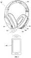
- FIG. 1illustrates an example of an embodiment of a headphone according to the present disclosure, an associated source media device wirelessly transmitting an audio signal to the headphone.
- FIG. 2illustrates a source media device transmitting an audio signal to the headphone of FIG. 1 through an audio cable.
- FIG. 3is a circuit diagram of a portion of an embodiment of an electrical circuit that may be employed in the headphone of FIGS. 1 and 2 in accordance with the present disclosure.
- FIG. 4is a plot showing an example waveform of acoustic noise that may be generated by the tactile vibration driver, and an anti-wave signal that may be generated by the noise cancellation unit to cancel the acoustic noise.
- FIG. 5is a simplified schematic block diagram of a portion an audio/tactile unit 300 that may be employed in the headphone of FIG. 1 or FIG. 2 in accordance with the present disclosure.
- FIG. 6is a simplified schematic block diagram of a portion an audio/tactile unit 300 that may be employed in the headphone of FIG. 1 or FIG. 2 in accordance with the present disclosure.
- operably couplerefers to both wireless (e.g., BLUETOOTH®, WiFi, ZIGBEE®, etc.) and wired (e.g., electrical, optical, etc.) connections.
- wirede.g., electrical, optical, etc.
- “Operably couple,” and its other formsmay also refer to both direct (i.e., nothing coupled in between operably coupled components) and indirect (i.e., other components coupled in between operably coupled components) connections.
- An “acoustic driver”is defined herein as transducer configured for the primary purpose of generating sound waves from an electrical signal, such as for the reproduction of speech, music, or other audible sound.
- An acoustic drivermay also be referred to as a “speaker.” Although a diaphragm of an acoustic driver may vibrate to produce sound waves, such vibrations are typically not felt in any significant manner by the user during normal operation of a headphone.
- a “tactile vibration driver”is defined herein as a transducer configured for the primary purpose of generating tactile vibrations that are to be felt by a user.
- a tactile vibration drivermay also produce some incidental, audible acoustic waves that, for purposes of this disclosure, are considered to be “acoustic noise.”
- a “bass frequency”is a relatively low audible frequency generally considered to be within the range extending from approximately 16 Hz to approximately 512 Hz.
- a “low bass frequency”refers to bass frequencies that may be felt as well as heard. Such low bass frequencies may be within the range extending from approximately 16 Hz to approximately 200 Hz.
- FIG. 1illustrates an embodiment of a headphone 100 according to the present disclosure.
- the headphone 100may be configured to be operated in a wireless mode with respect to a source media device 105 .
- the headphone 100is an over-the-ear headphone, although the headphone 100 may be an in-ear headphone or an on-ear headphone in accordance with additional embodiments of the present disclosure.
- the headphone 100includes two ear-cup assemblies 102 , which are connected to one another by a headband 104 .
- An acoustic driver as well as a tactile vibration driverare carried within each ear-cup assembly 102 .
- the headphone 100is configured to perform noise cancellation to reduce the effects of acoustic noise generated by the tactile vibration driver, as will be discussed further below with respect to FIGS. 3 and 4 .
- the headphone 100may be characterized as a wireless headphone, and includes a power source (e.g., a battery) because the power for driving the acoustic drivers and tactile vibration driver is not provided by the source media device 105 providing the audio signal in the wireless embodiment of FIG. 1 .
- the headphone 100may be operably coupled (e.g., “paired”) with a source media device 105 , such as a smartphone, using BLUETOOTH® technology, but other wireless communication protocols may also be employed, such as WiFi or infra-red (IR) technology, for example.
- the headphone 100may also include at least one control input for controlling operation of the headphone 100 .
- the at least one control inputmay include a power button 106 for powering the headphone 100 on and/or off when the headphone 100 .
- the power button 106may also be used to initiate a pairing sequence with a source media device 105 by, for example, pressing and holding the power button 106 .
- sequential pressing of the power button 106may cause the source media device 105 to sequentially pause and then commence play of the audio signal.
- pressing the power button 106may cause the smartphone to answer the call, after which pressing the power button 106 may cause the smartphone to drop the call.
- the at least one control inputmay also include an up/forward button 108 , and a down/backward button 110 .
- pressing the up/forward button 108may increase the volume of the headphone 100
- pressing the down/backward button 110may decrease the volume of the headphone 100 .
- Holding the up/forward button 108 while the headphone 100 is playing an audio signalmay skip forward media files in a list of media files of an associated source media device 105
- holding the down/backward button 110 while the headphone 100 is playing an audio signalmay skip forward media files in a list of media files of an associated source media device 105 in the wireless mode of operation.
- the headphone 100further includes a microphone 112 .
- the microphone 112may be used to generate an audio signal corresponding to the voice of the user for purposes of conducting telephone calls or conveying voice commands to the associated source media device 105 .
- the microphone 112may receive power from the power source carried by the headphone 100 , and the audio signal generated by the headphone may be conveyed to a microprocessor within the headphone 100 , and then wirelessly to the source media device 105 .
- FIG. 2illustrates an embodiment of a headphone 100 according to another embodiment of the present disclosure.
- the headphone 100may be configured to be operated in a wired mode with respect to the source media device 105 .
- the headphone 100may be used in a wired configuration by plugging one of the jacks 116 of the audio cable 101 into the jack 114 of the headphone 100 , and the other jack 116 of the audio cable 101 into the source media device 105 .
- the headphone 100may be configured such that operation of the at least one control input (e.g., the power button 106 , the up/forward button 108 , and/or the down/backward button 110 ), and/or the microphone 112 is altered upon insertion of the jack 116 of the audio cable 101 into the jack 114 of the headphone 100 .
- the at least one control inpute.g., the power button 106 , the up/forward button 108 , and/or the down/backward button 110
- the at least one control inputmay be used to provide an input signal for controlling operation of the associated source media device 105 through the audio cable 101 .
- a headphoneis described as being either a wireless headphone ( FIG. 1 ) or a wired headphone ( FIG. 2 ), embodiments of the disclosure also include headphones that can be operated in either wireless mode or a wired mode as desired.
- An example of such a headphoneis described in U.S. patent Ser. No. 15/832,527, entitled “Headphone with Adaptive Controls,” filed Dec. 5, 2017, the disclosure of which is incorporated herein in its entirety by this reference.
- FIG. 3is a simplified schematic block diagram of a portion an audio/tactile unit 300 that may be employed in the headphone 100 of FIG. 1 or FIG. 2 in accordance with the present disclosure.
- the headphonemay include an audio/tactile unit 300 as described below in each ear cup of the headphone.
- the headphone 100may include an acoustic driver 150 and a tactile vibration driver 152 .
- the audio/tactile unit 300may provide a noise cancellation unit (also referred to as “noise reducer” or “noise canceller” or variations thereof) in a noise cancellation path 160 including control logic configured to operate the headphone to receive an input signal 140 and reduce the effects of acoustic noise 142 generated by the tactile vibration driver 152 of the headphone 100 .
- noise cancellation unitalso referred to as “noise reducer” or “noise canceller” or variations thereof
- the noise cancellation path 160may include the inverse transfer function element(s) 154 configured to generate and add an anti-wave signal 144 to the input signal 140 for reproduction by the acoustic driver 150 .
- the input signal 140may be generated by the source media device 105 ( FIGS. 1 and 2 ) and/or an internal processor of the headphone 100 responsive to the source media device 105 .
- the acoustic driver 150(e.g., speaker) may be configured to convert an output signal 148 into audible sound waves 151 across the frequency range of the input signal 140 .
- the tactile vibration driver 152is a separate driver from the acoustic driver 150 that is configured to generate tactile vibrations 153 that are felt by the user.
- the tactile vibrations 153may be generated at particular frequencies of the source media to enhance the user experience.
- the source mediamay include music that is enhanced by vibrating with the bass frequencies.
- the source mediae.g., movies, gaming, etc.
- effectssuch as explosions that may be enhanced by vibrations being generated that are felt by the user. Specific examples of configurations of tactile vibration drivers are described in U.S. Pat. No.
- the input signal 140may be split and sent on a first channel toward the acoustic driver 150 , and on a second channel toward the tactile vibration driver 152 .
- the input signal 140may be passed through a filter 156 .
- the filter 156may be a low pass filter or a band pass filter depending on the desired frequency range for the tactile vibration driver 152 .
- many tactile vibration driverstend to be configured with a resonant frequency within the bass frequency range (e.g., 16 Hz to 512 Hz).
- the filter 156may be configured as a band pass filter configured to pass low bass frequencies in the band range extending from about 16 Hz to about 200 Hz, while attenuating frequencies outside of that frequency range.
- filter rangese.g., 20 Hz to 150 Hz
- Other filter rangesare also contemplated as desired for the desired effect, which may also be influenced by the resonant frequency of the source media and/or the resonant frequency of the tactile vibration driver 152 .
- a gain stage(not shown) may be incorporated with the filter 156 or a separate block before or after the filter 156 .
- the filtered input signal 146may be split and sent both to the inverse transfer function element(s) 154 and to the tactile vibration driver 152 , as shown in FIG. 3 .
- the tactile vibration driver 152generates the intended and desirable tactile vibrations 153 , but may also generate some unintended and undesirable acoustic noise 142 .
- the inverse transfer function element(s) 154are configured to apply a predetermined transfer function H(s) ⁇ 1 to the filtered input signal 146 to generate an anti-wave signal 144 .
- the anti-wave signal 144is summed (i.e., combined) with the input signal 140 to generate the output signal 148 , which is sent to the acoustic driver 150 and generates the intended audible sound waves 151 .
- the anti-wave signal 144forms a portion of the output signal 148 that causes destructive interference with acoustic noise 142 from the tactile vibrations. As a result, the amount of acoustic noise 142 generated by the tactile vibration driver 152 that is ultimately heard by the user may be reduced, or even eliminated in some embodiments.
- the inverse transfer function H(s) ⁇ 1may be based, at least in part, on an inverse of a determined transfer function H(s) of the tactile vibration driver 152 .
- the term “the transfer function”is represented by H(s)
- the term “inverse transfer function”is represented as H(s) ⁇ 1 .
- the inverse transfer function H(s) ⁇ 1may not be a perfect inverse of the determined transfer function H(s) of the tactile vibration driver 152 as discussed below.
- the transfer function H(s)may be determined by comparing the filtered input signal 146 to the acoustic noise 142 .
- a microphonemay be used to generate an electrical signal from the acoustic noise 142 (the microphone signal), and the microphone signal may be compared to the filtered input signal 146 .
- the transfer function H(s)is the function that, when applied to the filtered input signal 146 , will result in the signal corresponding to the acoustic noise 142 (represented by the microphone signal).
- the transfer function H(s)may be based, at least in part, on the configuration of the tactile vibration driver 152 (e.g., materials, configuration, dimensions, etc.).
- the transfer function H(s)may be additionally based on the configuration of the enclosure of the headphone 100 (e.g., shape, material, cavity, etc.) housing the tactile vibration driver 152 , as well as the position and/or orientation of the tactile vibration driver 152 and other components within the headphone 100 .
- the transfer function H(s)may include phase, frequency, amplitude information for the generated acoustic noise 142 related to an input signal. Such acoustic tests may be performed for the tactile vibration driver 152 located within the enclosure of the headphone in some embodiments to account for influences of other components of the headphone 100 .
- the transfer function H(s)may be determined once by the headphone manufacturer for any particular model of headphone. From that determined transfer function H(s), the inverse transfer function H(s) ⁇ 1 may be determined, and used in all headphones of the same particular model.
- the inverse transfer function H(s) ⁇ 1may also be adjusted to not be a perfect inverse of the determined transfer function H(s) for acoustic noise 142 from the tactile vibration driver 152 and other enclosure elements.
- the inverse transfer function H(s) ⁇ 1may also be adjusted to account for the transfer function of the acoustic path through the acoustic driver 150 as doing so may compensate for distortion of the anti-wave signal 144 passing through the acoustic driver 150 .
- the control logic of the inverse transfer function element(s) 154may be implemented using hardware components, software, or a combination thereof. If implemented in hardware, the specific configuration of hardware components may be arranged to perform the desired inverse transfer function H(s) ⁇ 1
- the inverse transfer function element(s) 154 and/or the filter 156 of the audio/tactile unit 300may be implemented with analog circuit components (e.g., op-amps, resistors, capacitors, etc.) arranged and coupled to achieve the desired filter range of the filter 156 and inverse transfer function H(s) ⁇ 1 for the inverse transfer function element(s) 154 .
- the instructionsmay be written and stored in a non-transitory storage medium for execution by a digital signal processor to perform the desired inverse transfer function H(s) ⁇ 1 for the inverse transfer function element(s) 154 .
- the filter 156may also be implemented in either hardware or software, and which may also be integrated with the design of the inverse transfer function element(s) 154 in some embodiments.
- audible sound waves 151are produced with the acoustic driver 150 responsive to the output signal 148 .
- Tactile vibrations 153 to be felt by a userare also produced by the tactile vibration driver 152 responsive to the filtered input signal 146 .
- the filter 156may filter the input signal 140 according to a desired frequency range to generate the filtered input signal 146 that is sent to the inverse transfer function elements 154 and the tactile vibration driver 152 , as previously discussed.
- Some acoustic noise 142may also be generated by the tactile vibration driver 152 , as previously discussed.
- the audible sound waves 151 generated by the acoustic driver 150include some “anti-noise” sound waves that interfere with and cancel the acoustic noise 142 , so as to reduce or eliminate the amount of acoustic noise 142 that is actually heard by the user.
- the anti-noise sound wavesare generated by the tactile vibration driver 152 in response to the portion of the output signal 148 corresponding to the anti-wave signal 144 generated by the inverse transfer function elements 154 .
- the inverse transfer function elements 154applies the predetermined inverse transfer function H(s) ⁇ 1 based, at least in part, on the transfer function H(s) attributed to the tactile vibration driver 152 and other elements of the headphone associated with the tactile vibration driver 152 . This noise cancellation is performed without the use of a microphone capturing environmental noise for the noise cancellation.
- FIG. 4is a simplified plot 400 of the acoustic noise 142 generated by the tactile vibration driver 152 ( FIG. 3 ) and the anti-wave signal 144 generated by the inverse transfer function element(s) 154 .
- the anti-wave signal 144is generated by applying the inverse transfer function H(s) ⁇ 1 to the filtered input signal to generate substantially the inverse of the acoustic noise 142 generated by the tactile vibration driver 152 .
- the inverse transfer function H(s) ⁇ 1 and the transfer function H(s) of the tactile vibration driver 152may not be perfect inverses of each other due to effects on the acoustic noise by the headphone environment and/or the anti-wave signal 144 passing through the summation and acoustic driver 150 .
- the acoustic driver 150when the anti-wave signal 144 added to the input signal 140 , the acoustic driver 150 generates audible sound waves 151 that include the reproduced input signal 140 as well as the anti-noise sound waves resulting from the anti-wave signal 144 .
- the anti-noise sound wavesreduces (e.g., cancel) the effects of the acoustic noise 142 so that the audible sound waves of the input signal 140 for the source media may be more clear, while the tactile vibration driver 152 still generates the tactile vibrations felt by the user but does not contribute audible sound to the experience of the user.
- FIG. 5is a simplified schematic block diagram of a portion an audio/tactile unit 300 that may be employed in the headphone 100 of FIG. 1 or FIG. 2 in accordance with the present disclosure.
- the headphonemay include an audio/tactile unit 300 as described below in each ear cup of the headphone.
- the audio/tactile unit 300may include an acoustic driver 150 , a filter 156 , and tactile vibration driver 152 with exhibiting the transfer function H(s) configured in a similar manner as with FIG. 3 .
- transfer function elements 554configured to apply the transfer function H(s) to the filtered input signal 146 (as opposed to its inverse) and then subtracting the resulting signal 544 from the input signal 140 prior to being received by the acoustic driver 150 to generate the output signal 148 converted to audible sound.
- the acoustics generated by the tactile vibration driver 152may be accounted for in the main acoustic path by removing the right portion of the signal from the acoustic driver 150 so that net acoustics generated by both drivers 150 , 152 is as if only the acoustic driver 150 was present in the headphone 100 .
- the transfer function H(s)is based, at least in part, on how much acoustics is generated by the tactile vibration driver, and the phase may be matched to the electrical input signal to the acoustic driver 150 .
- the “cancellation” effectmay be achieved electrically before the acoustic driver as opposed to through destructive interferences. Because of this subtraction, the acoustic driver 150 may reproduce less bass response during operation.
- the inverse transfer function H(s) ⁇ 1may be applied in the path that is received by the tactile vibration driver 152 .
- the inverse transfer function H(s) ⁇ 1may be applied to the filtered input signal 146 or the input signal 140 prior to driving the tactile vibration driver 152 such that the acoustic effects are reduced; however, doing so may reduce energy to cause the tactile vibration driver 152 to vibrate less and achieve a lower vibration effect. As such a situation may be less desirable, pulling energy from the acoustic driver 150 may be a preferable solution.
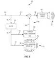
- FIG. 6is a simplified schematic block diagram of a portion an audio/tactile unit 300 that may be employed in the headphone 100 of FIG. 1 or FIG. 2 in accordance with the present disclosure.
- the headphonemay include an audio/tactile unit 300 as described below in each ear cup of the headphone.
- the audio/tactile unit 300may include an acoustic driver 150 , a filter 156 , and tactile vibration driver 152 with exhibiting the transfer function H(s) configured in a similar manner as with FIG. 3 .
- the noise cancellation path 660 of FIG. 6includes an energy detector 654 and a dynamic equalizer 655 .
- the dynamic equalizer 655may be configured to adjust (e.g., subtract) the needed energy for the input signal 140 for each frequency band to adjust the amount of acoustic energy is output by the acoustic driver 150 relative to the amount of acoustic energy output by the tactile vibration driver 152 .
- FFTFast Fourier Transform
- the energy determined to be in each frequency bandmay then be subtracted from the energy level by the dynamic equalizer 655 for each band of the input signal prior to being received by the acoustic driver 150 .
- the energy detector 654 and the dynamic equalizer 655may be implemented with a DSP.
- Embodiment 1a headphone comprising a housing, an acoustic driver within the housing and configured to generate acoustic sound waves responsive to an input signal, a tactile vibration driver within the housing and configured to generate tactile vibration sufficient to be felt by a user responsive to the input signal, and a noise cancellation unit coupled with the acoustic driver, the noise cancellation unit configured to generate an adjustment signal according to a transfer function associated with the tactile vibration driver generating acoustic noise incidental to the tactile vibrations, and adjust the input signal responsive to the adjustment signal to transmit an output signal for reproduction by the acoustic driver.
- Embodiment 2the headphone of Embodiment 1, wherein the predetermined transfer function is also associated with the tactile vibration driver when located within the housing.
- Embodiment 3the headphone of Embodiment 1 or Embodiment 2, wherein the noise cancellation unit is configured to: generate the adjustment signal by applying an inverse transfer function of the transfer function to generate an anti-wave signal; and adjust the input signal by summing the input signal and the anti-wave signal.
- Embodiment 4the headphone of Embodiment 3, wherein the noise cancellation unit includes analog components configured to implement the inverse transfer function.
- Embodiment 5the headphone of Embodiment 3, wherein the noise cancellation unit includes a digital signal processor configured to implement the inverse transfer function by executing instructions stored in a memory device.
- the noise cancellation unitincludes a digital signal processor configured to implement the inverse transfer function by executing instructions stored in a memory device.
- Embodiment 6the headphone of any one of Embodiments 1 through 5, wherein the noise cancellation unit is configured to generate the adjustment signal without the use of a microphone.
- Embodiment 7the headphone of any one of Embodiments 1 through 6, further comprising a filter operably coupled with the tactile vibration driver and the noise cancellation unit.
- Embodiment 8the headphone of Embodiment 7, wherein the filter includes a band pass filter configured to filter the input signal to pass bass frequencies to the tactile vibration driver and the noise cancellation unit.
- Embodiment 9the headphone of Embodiment 8, wherein the bass frequencies are set at low bass frequencies.
- Embodiment 10the headphone of any one of Embodiments 1 through 9, wherein the noise cancellation unit is configured to: generate the adjustment signal by applying the transfer function to generate an anti-wave signal; and adjust the input signal by subtracting the input signal and the anti-wave signal.
- Embodiment 11the headphone of Embodiment 1 or Embodiment 2, wherein the noise cancellation unit includes an energy detector coupled with a dynamic equalizer configured to adjust the input signal utilizing the dynamic equalizer to subtract signals at frequencies of the adjustment signal based on the transfer function associated with the tactile vibration driver.
- the noise cancellation unitincludes an energy detector coupled with a dynamic equalizer configured to adjust the input signal utilizing the dynamic equalizer to subtract signals at frequencies of the adjustment signal based on the transfer function associated with the tactile vibration driver.
- Embodiment 12the headphone of Embodiment 7, wherein the filter includes a low pass filter.
- Embodiment 13the headphone of any one of Embodiments 1 through 12, wherein the headphone is an over-ear or on-ear headphone or an in-ear headphone.
- Embodiment 14the headphone of any one of Embodiments 1 through 13, wherein the headphone is configured as at least one of a wired headphone or a wireless headphone.
- Embodiment 15the headphone of Embodiment 8, wherein the bass frequencies are set for a frequency range of 16 Hz to 512 Hz.
- Embodiment 16the headphone of Embodiment 8, wherein the bass frequencies are set for a frequency range of 16 Hz to 200 Hz.
- Embodiment 17the headphone of Embodiment 8, wherein the bass frequencies are set for a frequency range of 20 Hz to 150 Hz.
- Embodiment 18a method of operating a headphone, comprising: producing audio sound waves with an acoustic driver responsive to an input signal; producing tactile vibrations with a tactile vibration driver to be felt by a user responsive to the input signal; and reducing effects of incidental acoustic noise generated by the tactile vibration driver responsive to a noise cancellation unit generating an adjustment signal to apply to the input signal, the noise cancellation unit having its own transfer function based at least partially on a transfer function associated with operation of the tactile vibration driver.
- Embodiment 19the method of Embodiment 18, wherein the transfer function associated with operation of the tactile vibration driver is further based, at least in part, on an enclosure of the headphone housing the tactile vibration driver.
- Embodiment 20the method of Embodiment 18 or 19, further comprising filtering the input signal to apply a filtered input signal to drive the tactile vibration driver, wherein reducing incidental acoustic noise from the tactile vibration driver includes: generating an anti-wave signal as the adjustment signal by applying an inverse transfer function as the transfer function of the noise cancellation unit to the filtered input signal; and summing the anti-wave signal from and the input signal prior to producing the audio sound waves.
- Embodiment 21the method of Embodiment 18 or 19, further comprising filtering the input signal to apply a filtered input signal to drive the tactile vibration driver, wherein reducing incidental acoustic noise from the tactile vibration driver includes: generating an anti-wave signal as the adjustment signal by applying an inverse transfer function as the transfer function of the noise cancellation unit to the filtered input signal; and summing the anti-wave signal from and the input signal prior to producing the audio sound waves.
- Embodiment 22the method of any one of Embodiments 18 through 21, wherein generating the adjustment signal is performed without the use of a microphone capturing environmental noise.
- Embodiment 23A method of making one or more headphones, the method comprising: determining a transfer function of a first tactile vibration driver by measuring acoustic noise generated by the first tactile vibration driver within an enclosure of a first headphone housing the first tactile vibration driver; and producing one or more headphones including: an acoustic driver, a tactile vibration driver, and enclosure having the same transfer function as the first tactile vibration driver and the first headphone; and a noise cancellation unit operably coupled with the acoustic driver, the noise cancellation unit configured to generate an adjustment signal by passing the input signal through transfer function elements configured based, at least in part, on the determined transfer function, and transmit an output signal for reproduction by the acoustic driver responsive to adjusting the input signal with the adjustment signal.
Landscapes
- Physics & Mathematics (AREA)
- Engineering & Computer Science (AREA)
- Acoustics & Sound (AREA)
- Signal Processing (AREA)
- Multimedia (AREA)
- Soundproofing, Sound Blocking, And Sound Damping (AREA)
- Headphones And Earphones (AREA)
Abstract
Description
Claims (18)
Priority Applications (5)
| Application Number | Priority Date | Filing Date | Title |
|---|---|---|---|
| US15/898,383US10484792B2 (en) | 2018-02-16 | 2018-02-16 | Headphone with noise cancellation of acoustic noise from tactile vibration driver |
| EP19157211.4AEP3528508B1 (en) | 2018-02-16 | 2019-02-14 | Headphone with noise cancellation of acoustic noise from tactile vibration driver and method |
| CN201910120397.0ACN110166865B (en) | 2018-02-16 | 2019-02-18 | Noise Cancelling Headphones for Acoustic Noise from Haptic Vibration Drivers |
| CN202011140455.5ACN113068091B (en) | 2018-02-16 | 2019-02-18 | Earphone with noise cancellation of acoustic noise from haptic vibration driver |
| US16/670,861US11172302B2 (en) | 2018-02-16 | 2019-10-31 | Methods of using headphones with noise cancellation of acoustic noise from tactile vibration driver |
Applications Claiming Priority (1)
| Application Number | Priority Date | Filing Date | Title |
|---|---|---|---|
| US15/898,383US10484792B2 (en) | 2018-02-16 | 2018-02-16 | Headphone with noise cancellation of acoustic noise from tactile vibration driver |
Related Child Applications (1)
| Application Number | Title | Priority Date | Filing Date |
|---|---|---|---|
| US16/670,861ContinuationUS11172302B2 (en) | 2018-02-16 | 2019-10-31 | Methods of using headphones with noise cancellation of acoustic noise from tactile vibration driver |
Publications (2)
| Publication Number | Publication Date |
|---|---|
| US20190261088A1 US20190261088A1 (en) | 2019-08-22 |
| US10484792B2true US10484792B2 (en) | 2019-11-19 |
Family
ID=65440877
Family Applications (2)
| Application Number | Title | Priority Date | Filing Date |
|---|---|---|---|
| US15/898,383ActiveUS10484792B2 (en) | 2018-02-16 | 2018-02-16 | Headphone with noise cancellation of acoustic noise from tactile vibration driver |
| US16/670,861ActiveUS11172302B2 (en) | 2018-02-16 | 2019-10-31 | Methods of using headphones with noise cancellation of acoustic noise from tactile vibration driver |
Family Applications After (1)
| Application Number | Title | Priority Date | Filing Date |
|---|---|---|---|
| US16/670,861ActiveUS11172302B2 (en) | 2018-02-16 | 2019-10-31 | Methods of using headphones with noise cancellation of acoustic noise from tactile vibration driver |
Country Status (3)
| Country | Link |
|---|---|
| US (2) | US10484792B2 (en) |
| EP (1) | EP3528508B1 (en) |
| CN (2) | CN113068091B (en) |
Cited By (5)
| Publication number | Priority date | Publication date | Assignee | Title |
|---|---|---|---|---|
| USD924200S1 (en)* | 2019-11-25 | 2021-07-06 | Roland Corporation | Headphone |
| USD925490S1 (en)* | 2019-11-25 | 2021-07-20 | Roland Corporation | Guitar amplifier headphone |
| US11172302B2 (en)* | 2018-02-16 | 2021-11-09 | Skullcandy, Inc. | Methods of using headphones with noise cancellation of acoustic noise from tactile vibration driver |
| US11335313B2 (en) | 2017-12-15 | 2022-05-17 | Skullcandy, Inc. | Noise-canceling headphones including multiple vibration members and related methods |
| US11765503B2 (en) | 2021-04-15 | 2023-09-19 | Jian Deng | Integrated active noise-canceling wireless Bluetooth headphone |
Families Citing this family (7)
| Publication number | Priority date | Publication date | Assignee | Title |
|---|---|---|---|---|
| KR20170060114A (en) | 2014-09-24 | 2017-05-31 | 택션 테크놀로지 인코포레이티드 | Systems and methods for generating damped electromagnetically actuated planar motion for audio-frequency vibrations |
| US10573139B2 (en)* | 2015-09-16 | 2020-02-25 | Taction Technology, Inc. | Tactile transducer with digital signal processing for improved fidelity |
| WO2021044901A1 (en)* | 2019-09-03 | 2021-03-11 | ソニー株式会社 | Control device, speaker device, and sound output method |
| CN110856070B (en)* | 2019-11-20 | 2021-06-25 | 南京航空航天大学 | An active noise-isolating earmuff with voice enhancement |
| WO2021142136A1 (en) | 2020-01-07 | 2021-07-15 | The Regents Of The University Of California | Embodied sound device and method |
| CN112509549B (en)* | 2020-12-28 | 2022-08-05 | 重庆电子工程职业学院 | Active noise reduction method for ambient noise |
| WO2024212053A1 (en)* | 2023-04-10 | 2024-10-17 | 瑞声开泰声学科技(上海)有限公司 | Vibration noise processing method and apparatus, and device and readable storage medium |
Citations (26)
| Publication number | Priority date | Publication date | Assignee | Title |
|---|---|---|---|---|
| US5280543A (en)* | 1989-12-26 | 1994-01-18 | Yamaha Corporation | Acoustic apparatus and driving apparatus constituting the same |
| US6078672A (en) | 1997-05-06 | 2000-06-20 | Virginia Tech Intellectual Properties, Inc. | Adaptive personal active noise system |
| US6118878A (en) | 1993-06-23 | 2000-09-12 | Noise Cancellation Technologies, Inc. | Variable gain active noise canceling system with improved residual noise sensing |
| US6377145B1 (en) | 1999-03-03 | 2002-04-23 | Tokin Corporation | Vibration actuator having magnetic circuit elastically supported by a spiral damper with increased compliance |
| US7103188B1 (en) | 1993-06-23 | 2006-09-05 | Owen Jones | Variable gain active noise cancelling system with improved residual noise sensing |
| US7177433B2 (en) | 2000-03-07 | 2007-02-13 | Creative Technology Ltd | Method of improving the audibility of sound from a loudspeaker located close to an ear |
| EP1841278A1 (en) | 2006-03-27 | 2007-10-03 | Jui-Chen Huang | Loudspeaker with low-frequency oscillation |
| US20080112581A1 (en) | 2006-11-09 | 2008-05-15 | Stanley Kim | Vibrating earphone with enhanced base sound effect |
| US20080240484A1 (en) | 2005-11-10 | 2008-10-02 | Koninklijke Philips Electronics, N.V. | Device For and Method of Generating a Virbration Source-Driving-Signal |
| US7489785B2 (en) | 2002-06-28 | 2009-02-10 | Mark Donaldson | Noise cancellation system and headphone therefor |
| US20100005953A1 (en)* | 2008-07-08 | 2010-01-14 | Sony Corporation | Volume adjusting apparatus and volume adjusting method |
| US8045724B2 (en) | 2007-11-13 | 2011-10-25 | Wolfson Microelectronics Plc | Ambient noise-reduction system |
| US8054992B2 (en) | 2006-04-24 | 2011-11-08 | Bose Corporation | High frequency compensating |
| US8116472B2 (en) | 2005-10-21 | 2012-02-14 | Panasonic Corporation | Noise control device |
| US8254592B2 (en) | 2009-04-10 | 2012-08-28 | Apple Inc. | Electronic device and external equipment with configurable audio path circuitry |
| US8401205B2 (en) | 2006-11-07 | 2013-03-19 | Sony Corporation | Noise canceling system and noise canceling method |
| US8416959B2 (en) | 2009-08-17 | 2013-04-09 | SPEAR Labs, LLC. | Hearing enhancement system and components thereof |
| US8553900B2 (en) | 2010-05-14 | 2013-10-08 | Creative Technology Ltd | Noise reduction circuit with monitoring functionality |
| US8965028B2 (en) | 2012-08-23 | 2015-02-24 | Skullcandy, Inc. | Speakers, headphones, and kits related to vibrations in an audio system, and methods for forming same |
| US20150170633A1 (en)* | 2013-12-17 | 2015-06-18 | Kabushiki Kaisha Toshiba | Bone-conduction noise cancelling headphones |
| US20150189441A1 (en) | 2013-12-30 | 2015-07-02 | Skullcandy, Inc. | Headphones for stereo tactile vibration, and related systems and methods |
| US20160192060A1 (en)* | 2014-12-31 | 2016-06-30 | Skullcandy, Inc. | Methods of generating tactile user feedback utilizing headphone devices and related systems |
| US20160267898A1 (en) | 2015-03-12 | 2016-09-15 | Apple Inc. | Apparatus and method of active noise cancellation in a personal listening device |
| US9648412B2 (en) | 2015-02-06 | 2017-05-09 | Skullcandy, Inc. | Speakers and headphones related to vibrations in an audio system, and methods for operating same |
| US20170148428A1 (en) | 2015-11-19 | 2017-05-25 | Parrot Drones | Audio headset with active noise control, anti-occlusion control and passive attenuation cancelling, as a function of the presence or the absence of a voice activity of the headset user |
| US20170208380A1 (en) | 2016-01-14 | 2017-07-20 | Nura Holdings Pty Ltd | Headphones with combined ear-cup and ear-bud |
Family Cites Families (13)
| Publication number | Priority date | Publication date | Assignee | Title |
|---|---|---|---|---|
| US7203322B1 (en)* | 2003-05-16 | 2007-04-10 | Metrotech Corporation | Acoustic detector with noise cancellation |
| JP2008122729A (en)* | 2006-11-14 | 2008-05-29 | Sony Corp | Noise reducing device, noise reducing method, noise reducing program, and noise reducing audio outputting device |
| US8649526B2 (en)* | 2010-09-03 | 2014-02-11 | Nxp B.V. | Noise reduction circuit and method therefor |
| US9445184B2 (en)* | 2013-12-03 | 2016-09-13 | Bose Corporation | Active noise reduction headphone |
| EP3140718B1 (en)* | 2014-05-09 | 2019-01-02 | Sony Interactive Entertainment Inc. | Scheme for embedding a control signal in an audio signal using pseudo white noise |
| CN105530569A (en)* | 2014-09-30 | 2016-04-27 | 杜比实验室特许公司 | Headphone Hybrid Active Noise Cancellation and Noise Compensation |
| US9905217B2 (en) | 2014-10-24 | 2018-02-27 | Elwha Llc | Active cancellation of noise in temporal bone |
| US9454952B2 (en)* | 2014-11-11 | 2016-09-27 | GM Global Technology Operations LLC | Systems and methods for controlling noise in a vehicle |
| US10390139B2 (en)* | 2015-09-16 | 2019-08-20 | Taction Technology, Inc. | Apparatus and methods for audio-tactile spatialization of sound and perception of bass |
| EP3157266B1 (en)* | 2015-10-16 | 2019-02-27 | Nxp B.V. | Controller for a haptic feedback element |
| US10587946B2 (en) | 2017-12-05 | 2020-03-10 | Skullcandy, Inc. | Headphone with adaptive controls |
| US10872592B2 (en) | 2017-12-15 | 2020-12-22 | Skullcandy, Inc. | Noise-canceling headphones including multiple vibration members and related methods |
| US10484792B2 (en)* | 2018-02-16 | 2019-11-19 | Skullcandy, Inc. | Headphone with noise cancellation of acoustic noise from tactile vibration driver |
- 2018
- 2018-02-16USUS15/898,383patent/US10484792B2/enactiveActive
- 2019
- 2019-02-14EPEP19157211.4Apatent/EP3528508B1/enactiveActive
- 2019-02-18CNCN202011140455.5Apatent/CN113068091B/enactiveActive
- 2019-02-18CNCN201910120397.0Apatent/CN110166865B/enactiveActive
- 2019-10-31USUS16/670,861patent/US11172302B2/enactiveActive
Patent Citations (28)
| Publication number | Priority date | Publication date | Assignee | Title |
|---|---|---|---|---|
| US5280543A (en)* | 1989-12-26 | 1994-01-18 | Yamaha Corporation | Acoustic apparatus and driving apparatus constituting the same |
| US6118878A (en) | 1993-06-23 | 2000-09-12 | Noise Cancellation Technologies, Inc. | Variable gain active noise canceling system with improved residual noise sensing |
| US7103188B1 (en) | 1993-06-23 | 2006-09-05 | Owen Jones | Variable gain active noise cancelling system with improved residual noise sensing |
| US6078672A (en) | 1997-05-06 | 2000-06-20 | Virginia Tech Intellectual Properties, Inc. | Adaptive personal active noise system |
| US7110551B1 (en) | 1997-05-06 | 2006-09-19 | Adaptive Technologies, Inc. | Adaptive personal active noise reduction system |
| US6377145B1 (en) | 1999-03-03 | 2002-04-23 | Tokin Corporation | Vibration actuator having magnetic circuit elastically supported by a spiral damper with increased compliance |
| US7177433B2 (en) | 2000-03-07 | 2007-02-13 | Creative Technology Ltd | Method of improving the audibility of sound from a loudspeaker located close to an ear |
| US7489785B2 (en) | 2002-06-28 | 2009-02-10 | Mark Donaldson | Noise cancellation system and headphone therefor |
| US8116472B2 (en) | 2005-10-21 | 2012-02-14 | Panasonic Corporation | Noise control device |
| US20080240484A1 (en) | 2005-11-10 | 2008-10-02 | Koninklijke Philips Electronics, N.V. | Device For and Method of Generating a Virbration Source-Driving-Signal |
| EP1841278A1 (en) | 2006-03-27 | 2007-10-03 | Jui-Chen Huang | Loudspeaker with low-frequency oscillation |
| EP1841278B1 (en) | 2006-03-27 | 2008-12-10 | Jui-Chen Huang | Loudspeaker with low-frequency oscillation |
| US8054992B2 (en) | 2006-04-24 | 2011-11-08 | Bose Corporation | High frequency compensating |
| US8401205B2 (en) | 2006-11-07 | 2013-03-19 | Sony Corporation | Noise canceling system and noise canceling method |
| US20080112581A1 (en) | 2006-11-09 | 2008-05-15 | Stanley Kim | Vibrating earphone with enhanced base sound effect |
| US8045724B2 (en) | 2007-11-13 | 2011-10-25 | Wolfson Microelectronics Plc | Ambient noise-reduction system |
| US20100005953A1 (en)* | 2008-07-08 | 2010-01-14 | Sony Corporation | Volume adjusting apparatus and volume adjusting method |
| US8254592B2 (en) | 2009-04-10 | 2012-08-28 | Apple Inc. | Electronic device and external equipment with configurable audio path circuitry |
| US8416959B2 (en) | 2009-08-17 | 2013-04-09 | SPEAR Labs, LLC. | Hearing enhancement system and components thereof |
| US8553900B2 (en) | 2010-05-14 | 2013-10-08 | Creative Technology Ltd | Noise reduction circuit with monitoring functionality |
| US8965028B2 (en) | 2012-08-23 | 2015-02-24 | Skullcandy, Inc. | Speakers, headphones, and kits related to vibrations in an audio system, and methods for forming same |
| US20150170633A1 (en)* | 2013-12-17 | 2015-06-18 | Kabushiki Kaisha Toshiba | Bone-conduction noise cancelling headphones |
| US20150189441A1 (en) | 2013-12-30 | 2015-07-02 | Skullcandy, Inc. | Headphones for stereo tactile vibration, and related systems and methods |
| US20160192060A1 (en)* | 2014-12-31 | 2016-06-30 | Skullcandy, Inc. | Methods of generating tactile user feedback utilizing headphone devices and related systems |
| US9648412B2 (en) | 2015-02-06 | 2017-05-09 | Skullcandy, Inc. | Speakers and headphones related to vibrations in an audio system, and methods for operating same |
| US20160267898A1 (en) | 2015-03-12 | 2016-09-15 | Apple Inc. | Apparatus and method of active noise cancellation in a personal listening device |
| US20170148428A1 (en) | 2015-11-19 | 2017-05-25 | Parrot Drones | Audio headset with active noise control, anti-occlusion control and passive attenuation cancelling, as a function of the presence or the absence of a voice activity of the headset user |
| US20170208380A1 (en) | 2016-01-14 | 2017-07-20 | Nura Holdings Pty Ltd | Headphones with combined ear-cup and ear-bud |
Non-Patent Citations (4)
| Title |
|---|
| European Extended Search Report and Opinion for European Application No. 19157211.4, dated Apr. 5, 2019, 9 pages. |
| Löllmann et al., "Generalized Filter-Bank Equalizer for Noise Reduction with Reduced Signal Delay", Sep. 8, 2005, Proceedings of European Conference on Speech Communication and Technology (Interspeech), Lisbon, Portugal, pp. 2105-2108, XP055091633. |
| U.S. Appl. No. 15/832,527, filed Dec. 5, 2017, titled "Headphone With Adaptive Controls", to Sheffield et al., 19 pages. |
| U.S. Appl. No. 15/843,821, filed Dec. 15, 2017, titled "Noise-Canceling Headphones Including Multiple Vibration Members and Related Methods", to Hull et al, 31 pages. |
Cited By (6)
| Publication number | Priority date | Publication date | Assignee | Title |
|---|---|---|---|---|
| US11335313B2 (en) | 2017-12-15 | 2022-05-17 | Skullcandy, Inc. | Noise-canceling headphones including multiple vibration members and related methods |
| US11688382B2 (en) | 2017-12-15 | 2023-06-27 | Skullcandy, Inc. | Noise-canceling audio device including multiple vibration members |
| US11172302B2 (en)* | 2018-02-16 | 2021-11-09 | Skullcandy, Inc. | Methods of using headphones with noise cancellation of acoustic noise from tactile vibration driver |
| USD924200S1 (en)* | 2019-11-25 | 2021-07-06 | Roland Corporation | Headphone |
| USD925490S1 (en)* | 2019-11-25 | 2021-07-20 | Roland Corporation | Guitar amplifier headphone |
| US11765503B2 (en) | 2021-04-15 | 2023-09-19 | Jian Deng | Integrated active noise-canceling wireless Bluetooth headphone |
Also Published As
| Publication number | Publication date |
|---|---|
| CN110166865B (en) | 2020-10-30 |
| US20190261088A1 (en) | 2019-08-22 |
| CN110166865A (en) | 2019-08-23 |
| US11172302B2 (en) | 2021-11-09 |
| US20200068307A1 (en) | 2020-02-27 |
| EP3528508A1 (en) | 2019-08-21 |
| CN113068091A (en) | 2021-07-02 |
| EP3528508C0 (en) | 2023-06-07 |
| CN113068091B (en) | 2022-08-09 |
| EP3528508B1 (en) | 2023-06-07 |
Similar Documents
| Publication | Publication Date | Title |
|---|---|---|
| US11172302B2 (en) | Methods of using headphones with noise cancellation of acoustic noise from tactile vibration driver | |
| KR102196012B1 (en) | Systems and methods for enhancing performance of audio transducer based on detection of transducer status | |
| JP6389232B2 (en) | Short latency multi-driver adaptive noise cancellation (ANC) system for personal audio devices | |
| KR102129717B1 (en) | Systems and methods for adaptive noise cancellation including dynamic bias of coefficients of an adaptive noise cancellation system | |
| KR102245356B1 (en) | Frequency-shaped noise-based adaptation of secondary path adaptive response in noise-canceling personal audio devices | |
| CN102404658B (en) | Noise canceling headphone and noise canceling earmuff | |
| CN108076419B (en) | Linear resonant actuator controller | |
| US8422691B2 (en) | Audio outputting device, audio outputting method, noise reducing device, noise reducing method, program for noise reduction processing, noise reducing audio outputting device, and noise reducing audio outputting method | |
| JP5788972B2 (en) | Noise reduction circuit with monitor function | |
| JP6069829B2 (en) | Ear hole mounting type sound collecting device, signal processing device, and sound collecting method | |
| CN109936790A (en) | Noise-cancelling earphones including multiple vibrating components and related methods | |
| US20150296297A1 (en) | Anc active noise control audio headset with reduction of the electrical hiss | |
| CN206713019U (en) | Active noise reducing device and earphone | |
| CN102340717A (en) | Noise-canceling headphone | |
| JP2013110746A (en) | Audio head set having non-adaptive active noise control function for listening audio sound source and/or "hands-free" telephone function | |
| JP2015219527A (en) | Anc noise active control audio head set preventing influence of saturation of feedback microphone signal | |
| CN104602155A (en) | Wireless noise reduction earphone based on intelligent mobile terminal | |
| CN106465007B (en) | Control circuit for Active noise control and the method for Active noise control | |
| TWI822662B (en) | Headset charger node | |
| KR20240117579A (en) | Headsets with active noise cancellation and active noise cancellation methods | |
| JP6197930B2 (en) | Ear hole mounting type sound collecting device, signal processing device, and sound collecting method | |
| CN105744429A (en) | Headset noise reduction method based on mobile terminal, mobile terminal and noise reduction headset | |
| TWI501657B (en) | Electronic audio device | |
| US20240127786A1 (en) | Audio playback method, audio playback device, and storage medium | |
| JPH04107993U (en) | Electronic silencer and audio reproduction device using electronic silencer |
Legal Events
| Date | Code | Title | Description |
|---|---|---|---|
| FEPP | Fee payment procedure | Free format text:ENTITY STATUS SET TO UNDISCOUNTED (ORIGINAL EVENT CODE: BIG.); ENTITY STATUS OF PATENT OWNER: LARGE ENTITY | |
| AS | Assignment | Owner name:SKULLCANDY, INC., UTAH Free format text:ASSIGNMENT OF ASSIGNORS INTEREST;ASSIGNOR:SHEFFIELD, BRANDEN;REEL/FRAME:045209/0181 Effective date:20180313 | |
| STPP | Information on status: patent application and granting procedure in general | Free format text:NOTICE OF ALLOWANCE MAILED -- APPLICATION RECEIVED IN OFFICE OF PUBLICATIONS | |
| STPP | Information on status: patent application and granting procedure in general | Free format text:PUBLICATIONS -- ISSUE FEE PAYMENT VERIFIED | |
| STCF | Information on status: patent grant | Free format text:PATENTED CASE | |
| AS | Assignment | Owner name:PNC BANK, NATIONAL ASSOCIATION, PENNSYLVANIA Free format text:ASSIGNMENT OF SECURITY INTEREST;ASSIGNOR:SKULLCANDY, INC.;REEL/FRAME:055997/0703 Effective date:20210414 | |
| AS | Assignment | Owner name:PNC BANK, NATIONAL ASSOCIATION, PENNSYLVANIA Free format text:CORRECTIVE ASSIGNMENT TO CORRECT THE THE PATENT INFORMATION PREVIOUSLY RECORDED AT REEL: 055997 FRAME: 0710. ASSIGNOR(S) HEREBY CONFIRMS THE ASSIGNMENT;ASSIGNOR:SKULLCANDY, INC.;REEL/FRAME:059451/0760 Effective date:20210414 | |
| MAFP | Maintenance fee payment | Free format text:PAYMENT OF MAINTENANCE FEE, 4TH YEAR, LARGE ENTITY (ORIGINAL EVENT CODE: M1551); ENTITY STATUS OF PATENT OWNER: LARGE ENTITY Year of fee payment:4 | |
| AS | Assignment | Owner name:WELLS FARGO BANK, NATIONAL ASSOCIATION, MASSACHUSETTS Free format text:SECURITY INTEREST;ASSIGNOR:SKULLCANDY, INC.;REEL/FRAME:063489/0869 Effective date:20230428 | |
| AS | Assignment | Owner name:CRYSTAL FINANCIAL LLC (D/B/A SLR CREDIT SOLUTIONS), MASSACHUSETTS Free format text:SECURITY INTEREST;ASSIGNOR:SKULLCANDY, INC.;REEL/FRAME:063501/0918 Effective date:20230428 Owner name:SKULLCANDY, INC., UTAH Free format text:TERMINATION OF ASSIGNMENT;ASSIGNOR:PNC BANK, NATIONAL ASSOCIATION;REEL/FRAME:063502/0910 Effective date:20230428 | |
| AS | Assignment | Owner name:SKULLCANDY, INC., UTAH Free format text:RELEASE BY SECURED PARTY;ASSIGNOR:CRYSTAL FINANCIAL LLC (D/B/A SLR CREDIT SOLUTIONS;REEL/FRAME:067867/0318 Effective date:20240614 |