US10483806B2 - Multi-mode energy receiver system - Google Patents
Multi-mode energy receiver systemDownload PDFInfo
- Publication number
- US10483806B2 US10483806B2US15/786,506US201715786506AUS10483806B2US 10483806 B2US10483806 B2US 10483806B2US 201715786506 AUS201715786506 AUS 201715786506AUS 10483806 B2US10483806 B2US 10483806B2
- Authority
- US
- United States
- Prior art keywords
- power
- antenna
- signal
- receiving unit
- oscillating
- Prior art date
- Legal status (The legal status is an assumption and is not a legal conclusion. Google has not performed a legal analysis and makes no representation as to the accuracy of the status listed.)
- Expired - Fee Related, expires
Links
Images


Classifications
- H—ELECTRICITY
- H02—GENERATION; CONVERSION OR DISTRIBUTION OF ELECTRIC POWER
- H02J—CIRCUIT ARRANGEMENTS OR SYSTEMS FOR SUPPLYING OR DISTRIBUTING ELECTRIC POWER; SYSTEMS FOR STORING ELECTRIC ENERGY
- H02J50/00—Circuit arrangements or systems for wireless supply or distribution of electric power
- H02J50/10—Circuit arrangements or systems for wireless supply or distribution of electric power using inductive coupling
- H02J50/12—Circuit arrangements or systems for wireless supply or distribution of electric power using inductive coupling of the resonant type
- H—ELECTRICITY
- H02—GENERATION; CONVERSION OR DISTRIBUTION OF ELECTRIC POWER
- H02J—CIRCUIT ARRANGEMENTS OR SYSTEMS FOR SUPPLYING OR DISTRIBUTING ELECTRIC POWER; SYSTEMS FOR STORING ELECTRIC ENERGY
- H02J50/00—Circuit arrangements or systems for wireless supply or distribution of electric power
- H02J50/20—Circuit arrangements or systems for wireless supply or distribution of electric power using microwaves or radio frequency waves
- H—ELECTRICITY
- H02—GENERATION; CONVERSION OR DISTRIBUTION OF ELECTRIC POWER
- H02J—CIRCUIT ARRANGEMENTS OR SYSTEMS FOR SUPPLYING OR DISTRIBUTING ELECTRIC POWER; SYSTEMS FOR STORING ELECTRIC ENERGY
- H02J50/00—Circuit arrangements or systems for wireless supply or distribution of electric power
- H02J50/10—Circuit arrangements or systems for wireless supply or distribution of electric power using inductive coupling
- H—ELECTRICITY
- H02—GENERATION; CONVERSION OR DISTRIBUTION OF ELECTRIC POWER
- H02J—CIRCUIT ARRANGEMENTS OR SYSTEMS FOR SUPPLYING OR DISTRIBUTING ELECTRIC POWER; SYSTEMS FOR STORING ELECTRIC ENERGY
- H02J50/00—Circuit arrangements or systems for wireless supply or distribution of electric power
- H02J50/20—Circuit arrangements or systems for wireless supply or distribution of electric power using microwaves or radio frequency waves
- H02J50/23—Circuit arrangements or systems for wireless supply or distribution of electric power using microwaves or radio frequency waves characterised by the type of transmitting antennas, e.g. directional array antennas or Yagi antennas
- H—ELECTRICITY
- H02—GENERATION; CONVERSION OR DISTRIBUTION OF ELECTRIC POWER
- H02J—CIRCUIT ARRANGEMENTS OR SYSTEMS FOR SUPPLYING OR DISTRIBUTING ELECTRIC POWER; SYSTEMS FOR STORING ELECTRIC ENERGY
- H02J50/00—Circuit arrangements or systems for wireless supply or distribution of electric power
- H02J50/70—Circuit arrangements or systems for wireless supply or distribution of electric power involving the reduction of electric, magnetic or electromagnetic leakage fields
- H—ELECTRICITY
- H02—GENERATION; CONVERSION OR DISTRIBUTION OF ELECTRIC POWER
- H02J—CIRCUIT ARRANGEMENTS OR SYSTEMS FOR SUPPLYING OR DISTRIBUTING ELECTRIC POWER; SYSTEMS FOR STORING ELECTRIC ENERGY
- H02J50/00—Circuit arrangements or systems for wireless supply or distribution of electric power
- H02J50/90—Circuit arrangements or systems for wireless supply or distribution of electric power involving detection or optimisation of position, e.g. alignment
- H02J7/025—
- H02J7/027—
- H04B5/0037—
- H04B5/0075—
- H04B5/0093—
- H—ELECTRICITY
- H04—ELECTRIC COMMUNICATION TECHNIQUE
- H04B—TRANSMISSION
- H04B5/00—Near-field transmission systems, e.g. inductive or capacitive transmission systems
- H04B5/20—Near-field transmission systems, e.g. inductive or capacitive transmission systems characterised by the transmission technique; characterised by the transmission medium
- H04B5/24—Inductive coupling
- H04B5/26—Inductive coupling using coils
- H04B5/266—One coil at each side, e.g. with primary and secondary coils
- H—ELECTRICITY
- H04—ELECTRIC COMMUNICATION TECHNIQUE
- H04B—TRANSMISSION
- H04B5/00—Near-field transmission systems, e.g. inductive or capacitive transmission systems
- H04B5/70—Near-field transmission systems, e.g. inductive or capacitive transmission systems specially adapted for specific purposes
- H04B5/79—Near-field transmission systems, e.g. inductive or capacitive transmission systems specially adapted for specific purposes for data transfer in combination with power transfer
- H—ELECTRICITY
- H01—ELECTRIC ELEMENTS
- H01Q—ANTENNAS, i.e. RADIO AERIALS
- H01Q19/00—Combinations of primary active antenna elements and units with secondary devices, e.g. with quasi-optical devices, for giving the antenna a desired directional characteristic
- H01Q19/10—Combinations of primary active antenna elements and units with secondary devices, e.g. with quasi-optical devices, for giving the antenna a desired directional characteristic using reflecting surfaces
- H—ELECTRICITY
- H01—ELECTRIC ELEMENTS
- H01Q—ANTENNAS, i.e. RADIO AERIALS
- H01Q3/00—Arrangements for changing or varying the orientation or the shape of the directional pattern of the waves radiated from an antenna or antenna system
- H01Q3/02—Arrangements for changing or varying the orientation or the shape of the directional pattern of the waves radiated from an antenna or antenna system using mechanical movement of antenna or antenna system as a whole
- H01Q3/04—Arrangements for changing or varying the orientation or the shape of the directional pattern of the waves radiated from an antenna or antenna system using mechanical movement of antenna or antenna system as a whole for varying one co-ordinate of the orientation
- H—ELECTRICITY
- H01—ELECTRIC ELEMENTS
- H01Q—ANTENNAS, i.e. RADIO AERIALS
- H01Q7/00—Loop antennas with a substantially uniform current distribution around the loop and having a directional radiation pattern in a plane perpendicular to the plane of the loop
- H—ELECTRICITY
- H01—ELECTRIC ELEMENTS
- H01Q—ANTENNAS, i.e. RADIO AERIALS
- H01Q9/00—Electrically-short antennas having dimensions not more than twice the operating wavelength and consisting of conductive active radiating elements
- H01Q9/04—Resonant antennas
- H01Q9/30—Resonant antennas with feed to end of elongated active element, e.g. unipole
- H01Q9/42—Resonant antennas with feed to end of elongated active element, e.g. unipole with folded element, the folded parts being spaced apart a small fraction of the operating wavelength
- H—ELECTRICITY
- H02—GENERATION; CONVERSION OR DISTRIBUTION OF ELECTRIC POWER
- H02M—APPARATUS FOR CONVERSION BETWEEN AC AND AC, BETWEEN AC AND DC, OR BETWEEN DC AND DC, AND FOR USE WITH MAINS OR SIMILAR POWER SUPPLY SYSTEMS; CONVERSION OF DC OR AC INPUT POWER INTO SURGE OUTPUT POWER; CONTROL OR REGULATION THEREOF
- H02M1/00—Details of apparatus for conversion
- H02M1/12—Arrangements for reducing harmonics from AC input or output
Definitions
- the present disclosurerelates to receiving wireless power in electric or electronic devices and more particularly to improving the wireless reception of power to devices for charging and/or sustaining power to those device loads.
- a devicein certain embodiments, includes a processor configured to identify a power transferring device and to determine a range configuration relative to the power transferring device, and to determine a power status of the device.
- the devicealso includes a first antenna configured to receive an oscillating power signal from the power transferring device at a first selected frequency based on the range configuration relative to the power transferring device, and on the power status of the device, and a first rectifier circuit configured to convert the oscillating power signal from the first antenna at the first selected frequency into a direct-current signal to charge a device load.
- a methodin certain embodiments, includes identifying, by a power receiving unit, a power transferring unit in a proximity of the power receiving unit, determining a range configuration between the power transferring unit and the power receiving unit, and determining a power status of the power receiving unit.
- the methodalso includes selecting a first antenna in the power receiving unit based on the range configuration between the power transferring unit and the power receiving unit, and on the power status of the power receiving circuit, receiving, with the first antenna, an oscillating power signal from the power transferring unit at a selected frequency, converting the oscillating power signal from the power transferring unit at the selected frequency into a direct-current signal, and providing the direct-current signal to a device load.
- a non-transitory, computer readable mediumthat stores instructions which, when executed by a processor in a computer, cause the computer to perform a method.
- the methodincludes: identifying, by a power receiving unit, a power transferring unit in a proximity of the power receiving unit, determining a range configuration between the power transferring unit and the power receiving unit, and determining a power status of the power receiving unit.
- the methodalso includes selecting a first antenna in the power receiving unit based on the range configuration between the power transferring unit and the power receiving unit, and on the power status of the power receiving circuit, receiving, with the first antenna, an oscillating power signal from the power transferring unit at a selected frequency, converting the oscillating power signal from the power transferring unit at the selected frequency into a direct-current signal, and providing the direct-current signal to a device load.
- FIG. 1Ais a schematic illustration of a system for providing intelligent wireless power to a device load, including a power transferring unit (PTU) and a power receiving unit (PRU), according to some embodiments.
- PTUpower transferring unit
- PRUpower receiving unit
- FIG. 1Bis a schematic illustration of a PRU, according to some embodiments.
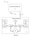
- FIG. 2is a block diagram of a PRU, according to some embodiments.
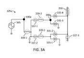
- FIGS. 3A-Billustrate rectifier circuits used in RF to DC current conversion in a PRU, according to some embodiments.
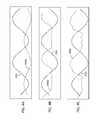
- FIGS. 4A-Cillustrate rectified waveforms as provided by a rectifier circuit in a PRU, according to some embodiments.
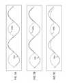
- FIGS. 5A-Cillustrate rectified waveforms as provided by a rectifier circuit in a PRU, according to some embodiments.
- FIGS. 6A-Billustrate block diagrams of a RF to a DC conversion circuit, according to some embodiments.
- FIG. 7is a flowchart illustrating steps in a method for managing, from a power receiving unit, a power transfer from a PTU, according to some embodiments.
- some embodiments as disclosed hereinprovide a central power receiving unit that may be installed or coupled with a mobile device (e.g., cell phones, laptops, notepads, and the like) for charging within the enclosure of a car. Accordingly, in embodiments as disclosed herein a driver can focus on the road rather than in looking for a plug to connect a power cord for a device, thereby enhancing road safety.
- a mobile devicee.g., cell phones, laptops, notepads, and the like
- the present disclosureincludes a system and method of receiving wireless power intelligently in a device. Accordingly, embodiments consistent with the present disclosure receive a directed power signal wirelessly from a power transferring unit (PTU) in a power receiving unit (PRU) in a first mode of operation (e.g., when the PRU is in the proximity of a far field range of the PTU). In other aspects, embodiments as disclosed herein include receiving a field (e.g., a resonant magnetic field) wirelessly and inductively coupling the field in the PRU at a resonant frequency of a receiver circuit in a second mode of operation (e.g., when the PRU is in the proximity of a near field range of the PTU).
- a fielde.g., a resonant magnetic field
- a power transfer from the PTU to the PRUis managed selectively and efficiently.
- Embodiments as disclosed hereinreceive power as desired in the first mode of operation, the second mode of operation, or a combination of both modes simultaneously.
- embodiments as disclosed hereintake into consideration a power requirement of the PRU, and its range relative to the PTU.
- multiple PRU'smay receive power from a single PTU, wherein the PRUs are sorted according to a prioritization based on the power requirements and range of each PRU relative to the PTU.
- the PRUincludes a far field receiver configured to wirelessly receive the directed power signal transmitted from the far field transmitter.
- the PRUmay also include a capture resonator configured to inductively capture resonant magnetic power in the near field generated by the source resonator.
- the frequency range of the power received in embodiments consistent with the present disclosuremay include, without limitation, a radio-frequency (RF), a low-frequency (LF) inductive magnetic, a high-frequency (HF) resonant magnetic field, or any combination of the above.
- frequency of any power receivedmay be, but is not limited to, any frequency between about 80 kHz to about 300 kHz (e.g., 110 kHz, 232 kHz, 250 kHz, 278 kHz, 915 MHz, 6.78 MHz, 13.56 MHz, 2.4 GHz or 5.8 GHz).
- Some embodimentsinclude a method of managing multimode receipt of wireless power.
- the methodincludes optimizing the wireless transfer of power from the PTU in at least the first mode of operation, the second mode of operation, or the two modes of operation simultaneously.
- the methodincludes capturing and receiving the optimized power transferred wirelessly over varying distances by one or more power receiving units (PRU's).
- PRU'spower receiving units
- Some embodimentsinclude a micro-controller circuit (MCC) configured to dynamically update a status of a range configuration between the PRU and the PTU to maximize the amount of power transferred between the devices in a dual mode, when available.
- MCCmicro-controller circuit
- some embodimentsinclude a power harvesting configuration that exploits the large amount of unused digital data propagating at RF frequencies wirelessly to convert the digital signals into power transferred to the PRU.
- the MCCincludes the reception and availability of the digital signals for harvesting. Moreover, in some embodiments the MCC is further configured to prioritize the desire for power for one or more PRU's in close proximity of the PTU. Thus, the load on the PTU is optimized for the needs of the one or multiple PRU's benefiting from the power transfer.
- the present disclosureaddresses the shortcomings of existing single-mode wireless power receiving systems such as low power transfer from a far field source or the limited spatial freedom of near field power transfer inherent to these technologies.
- embodiments consistent with the present disclosureobviate a need for traditional wired or cabled power delivery methods.
- Advantages of the present disclosureinclude increased efficiency, added redundancy for applications where critical loss of available power could be detrimental to the user and optional spatial versatility when lower power transfer rates are acceptable while providing power to or charging an electric or electronic device.
- FIG. 1Aillustrates a system 10 for receiving intelligent wireless power in a device in accordance with the principles of the present disclosure.
- System 10includes PTU 12 and PRU 14 .
- PTU 12is configured to transmit a directed power signal 16 wirelessly in a first mode of operation to PRU 14 .
- PTU 12is further configured to generate an inductively coupled (e.g., a resonant magnetic field) power signal 18 wirelessly in a second mode of operation.
- PRU 14is configured to receive the directed power signal 16 from PTU 12 when PRU 14 is in the far field range of PTU 12 . Further, PRU 14 is also configured to receive inductively coupled power signal 18 in the second mode when PRU 14 is in the proximity of a near field range of PTU 12 .
- PRU 14includes a micro-computer circuit (MCC) 36 , which is a processor configured to identify PTU 12 , to determine a range configuration between PRU 14 and PTU 12 , and to determine a power status of PRU 14 .
- MCCmicro-computer circuit
- PRU 14may also include antenna 46 , and antenna 56 .
- Antennas 46 and 56may be configured to receive oscillating power signals (e.g., directed propagating power signal 16 and inductively coupled power signal 18 ) from PTU 12 .
- Each of directed power signal 16 and inductively coupled signal 18may oscillate at a selected frequency.
- directed power signal 16is a RF signal at about 915 MHz
- inductively coupled signal 18is a RF magnetic field oscillating at 6.7 MHz, or at any frequency in a range between about 80 kHz to 300 kHz.
- the frequency of oscillation of directed power signals 16 and inductively coupled power signal 18may be indicative of the range configuration of PRU 14 relative to PTU 12 .
- a directed propagating RF signal oscillating at approximately 915 MHzmay be desirable.
- an inductively coupled power signal oscillating at approximately 6.7 MHz or even lowere.g. 80-300 kHz
- the choice between receiving power from directed power signal 16 , from inductively coupled power signal 18 , or from any combination of both,is selected by MCC 36 based on a power status of PRU 14 .
- PRU 14when PRU 14 is substantially depleted of power, it may be desirable to recharge using both directed power signal 16 and inductively coupled power signal 18 , from PTU 12 , simultaneously (as long as the range configuration between PTU 12 and PRU 14 is within the near field).
- PRU 14also includes a first and a second rectifier circuits 40 a and 40 b , configured to convert the oscillating power signal ( 18 and 16 , respectively) from antennas 46 and 56 at the selected frequency, into a direct-current signal to charge a device load 60 .
- PRU 14includes a far field receiver 26 configured to wirelessly receive the directed power signal 16 transmitted from PTU 12 when PRU 14 is within a far field range of PTU 12 .
- PRU 14also includes a capture resonator 28 configured to capture inductively coupled power signal 18 generated by PTU 12 when PRU 14 is within a near field range of PTU 12 .
- PRU 14includes an MCC 36 configured to intelligently manage the power transfer in the near field mode, the far field mode, or both modes, as desired.
- a communications circuit 38is configured to communicate information between PTU 12 and PRU 14 .
- a rectifier circuit 40 ais configured to convert power from a capture resonator 28 and provide the power to a device load 60 .
- a rectifier circuit 40 bis configured to convert power from a far field receiver 26 and provide the converted power to device load 60 .
- Rectifier circuits 40 a and 40 bwill be collectively referred to, hereinafter, as rectifier circuits 40 .
- rectifier circuits 40include an amplifier circuit to amplify the oscillating power signal from antennas 46 and 56 , and to provide an amplified oscillating signal to a rectifying portion of rectifier circuits 40 .
- antenna 46 in capture resonator 28includes a capture coil operatively connected to an impedance matching circuit (IMC) 48 .
- far field receiver 26includes a signal conversion module 54 and a far field receiver antenna(s) 56 .
- directed power signal 16 and inductively coupled field 18include an oscillating power signal having a bandwidth.
- directed power signal 16 oscillating at 915 MHzmay have a bandwidth of approximately 50 MHz, or more.
- inductively coupled field 18 oscillating at 6.7 MHzmay have a bandwidth of approximately 20 MHz, or more.
- device load 60may include multiple devices attached to a docking station in PRU 14 . Accordingly, rectifier circuits 40 may be configured to convert portions of the oscillating power signal within separate portions of the bandwidth to charge each of the multiple devices.
- transmitters and resonators as disclosed hereinconvert RF signals from instruments and devices to directed power signal 16 and inductively coupled signal 18 oscillating at an industrial, scientific and medical (ISM) frequency band appropriately optimized for the application of the system and within accordance of regulatory rules and laws governing such wireless operations.
- ISMindustrial, scientific and medical
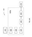
- FIG. 1Bis a schematic illustration of PRU 14 , according to some embodiments.
- PRU 14may include a communications circuit 138 configured to communicate information between PTU 12 and PRU 14 (e.g., communications circuit 38 ).
- Antenna 165is configured to wirelessly receive a directed power signal 116 transmitted from PTU 12 .
- antenna 165is a far field receiver configured to wirelessly receive the directed power signal transmitted from the far field transmitter.
- a passively-tuned integrated circuit (PTIC) 120 amay be configured to amplify directed power signal 116 from antenna 165 .
- PTIC 120 ais configured to dynamically tune a transmission circuit for various requirements (e.g., frequencies of operation).
- a RF to DC circuit 125 rfconverts directed power signal 116 from a RF oscillating signal provided by PTIC 120 a into a DC signal having a received voltage and a selected current.
- RF to DC circuit 125 rfmay include a rectifier circuit as disclosed herein (e.g., rectifier circuits 40 ).
- Voltage control 127adjusts the received voltage to a pre-selected value and provides a directed power signal to a charge management IC 150 .
- PRU 14includes an Rx resonator 160 r configured to receive an inductively coupled field from PTU 12 .
- the inductively coupled fieldis a magnetic field modulated at a low RF (e.g., 6.78 MHz, 13.56 MHz, and the like) compared to the operation frequency of antenna 165 (e.g., 915 MHz).
- the RF of the magnetic fieldtuned to a resonant frequency of Rx resonator 160 r .
- the resonant frequency of Rx resonator 160 ris tuned to the frequency of inductively coupled power signal 118 by PTIC 120 b .
- PTIC 120 bis configured to dynamically tune a receiver circuit for various requirements (e.g., frequencies of operation). Accordingly, in some embodiments, PTIC 120 b may include a source coil operatively connected to an IMC (e.g., IMC 48 ). Rx resonator 160 r initiates a power transfer from PTU 12 when PRU 14 is located within a near field range of PTU 12 . Rectifier 125 m is configured to convert the inductively coupled field (e.g., a low RF modulated magnetic field) into a DC power signal including a voltage and a current. DC to DC converter 115 amplifies the DC power signal from rectifier 125 m and provides an inductive power signal at a specified voltage (e.g., 3.3V) to charge management IC 150 .
- IMCe.g., IMC 48
- Rectifier 125 mis configured to convert the inductively coupled field (e.g., a low RF modulated magnetic field) into a DC power
- charge management IC 150includes a USB controller configured to handle a USB-type coupling with external devices (e.g., a device 187 , USB to USB port 182 , and USB socket 105 ).
- Charge management IC 150provides a power signal to battery 170 , at a selected DC voltage and a selected DC current. Accordingly, charge management IC 150 combines the directed power signal from voltage control 127 and the inductive power signal to provide a power signal that charges battery 170 .
- charge management IC 150may select only one or the other of the directed power signal or the inductive power signal, depending on their availability and the mode of operation of PRU 14 , to provide the power signal to battery 170 .
- PRU 14is coupled with device 187 through a device socket 185 .
- Device 187may be any type of mobile electronic appliance such as a computer, a laptop computer, a mobile phone, smart phone, tablet computer, and tablet phone.
- battery 170is a battery for device 187 , integrally installed in device 187 , or independently coupled to charge management IC 150 .
- device socket 185may support multiple devices 187 configured to be charged by PRU 14 .
- battery 170is a reserve battery and may be charged via USB socket 105 and USB port 182 by a direct DC power source such as a laptop/computer, wall adaptor or power bank.
- a direct DC power sourcesuch as a laptop/computer, wall adaptor or power bank.
- device 187may be charged at a later time from the charge in battery 170 (e.g., when PRU 14 is unplugged from a DC power source in USB socket 105 ).
- USB socket 105 and USB port 182may be used for charging device 187 from the direct DC power source.
- device 187may be a phone externally coupled to USB socket 105 for charging, as a power bank.
- PRU 14may charge an external device via USB socket 105
- USB port 182may receive a direct source of power coupled through USB socket 105 to charge battery 170 . Accordingly, embodiments consistent with the present disclosure provide device 187 with multiple options for charging.
- PRU 14includes a MCC 100 and a memory 155 .
- MCC 100may be as described in detail above with regard to MCC 36 .
- MCC 100is configured to control the receiving of the directed power signal at antenna 165 from PTU 12 when PRU 14 is in the proximity of a far field range of PTU 12 .
- MCC 100is configured to control the coupling of an inductive field wirelessly provided by PTU 12 , to the resonate magnetic field in the second mode when PRU 14 is in the proximity of a near field coupling range of PTU 12 .
- MCC 100may be further configured to control charge management IC 150 wherein power is transferred to PRU 14 from PTU 12 by managing the directed power signal and the resonant magnetic field to deliver power as needed by the first mode of operation, the second mode of operation, or both modes of operation and with consideration to the power requirement of PRU 14 , a priority value for transferring power to PRU 14 , and a range configuration between PTU 12 and PRU 14 .
- MCC 100may be configured to manage and determine the power requirement of PRU 14 and the priority value for transferring power to PRU 14 in view of the range configuration between PTU 12 and PRU 14 .
- the power requirement of PRU 14may include a power requirement of device 187 docked in device socket 185 .
- Memory 155may include instructions to cause MCC 100 , upon successfully establishing a communication link with PTU 12 via a communication protocol, and upon determining the presence of a corresponding software program installed on a device capable of running the software will provide relevant wireless power transfer session data in a visual format via said software program.
- the second MCCis integrated into one or more of the IC components in device 187 .
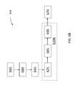
- FIG. 2is a schematic illustration of a PRU 214 , according to some embodiments.
- PRU 214includes a battery 270 , according to some embodiments.
- battery 270includes a charge reserve battery with capacity to deliver current from about 1800 milliamps per hour (maH) to about 2800 maH.
- a antenna 280is activated by controller 290 to provide a signal to a PTU (e.g., PTU 12 ).
- antenna 280is a BlueTooth antenna.
- the signal provided by antenna 280 to the PTUmay indicate a power requirement for battery 270 , or a range configuration between the PTU and PRU 214 .
- DC to DC converter 115amplifies a control signal for antenna 280 to controller 290 .
- the control signal for antenna 280may be provided by a power management IC (PMIC) 200 .
- PMIC 200provides a 5-9V power signal to device 287 , and a 3.5-4.2V power signal to reserve battery 270 .
- PMIC 200may include a switch configured to shift power transfer between device 287 and reserve battery 270 (e.g., when device 287 is de-docked into PRU 214 , or when device 287 is fully charged), or from battery 270 to a mobile device (e.g., device 287 , when docked into PRU 214 , or when battery 270 is fully charged).
- Device 287may also couple with antenna 280 through a bluetooth connection. Accordingly, device 287 may be an external device docked onto PRU 214 by a user, for re-charging (e.g., device 187 ).
- PRU 214To receive the transferred power from the PTU, PRU 214 includes a resonator 260 that couples with matching circuit 240 .
- Matching circuit 240may tune resonator 260 to a particular RF frequency of an inductively coupled near field power signal provided by the PTU (e.g., a RF resonant magnetic field).
- the inductively coupled near field power signalis provided to ASIC 220 and to a diode 250 - 1 (e.g., at 5V and 2 A).
- Antenna 265is configured to receive a RF directed power transferred by the PTU, and is coupled with RF to DC circuit 225 rf which provides a DC power signal (e.g., at 5V and 200 mA) to an ideal diode 250 - 2 .
- RF to DC circuit 225 rfmay be a rectifier circuit as disclosed herein (e.g., rectifier circuits 40 and 125 rf ).
- a device cable 205provides direct power to ideal diode 250 - 3 (e.g., at 5V and 2.5 A).
- diodes 250Ideal diodes 250 - 1 250 - 2 and 250 - 3 will be collectively referred to, hereinafter, as “diodes 250 .”
- the configuration of diodes 250 in PRU 214enables PMIC 200 to receive power signals from three different sources: inductively coupled near field power signal, RF directed power signal (both from the PTU), and from an external source through device cable 205 .
- any one of antennas 280 , 265 , and resonator 260may be configured to detect multiple wireless signals operating at multiple frequencies. Accordingly, PMIC may be further configured to tune antenna 280 , 265 or resonator 260 at a frequency of one of the multiple wireless signals and to cause RF to DC circuit 225 rf to convert at least one of the wireless signals into the direct-current signal.
- PMIC 200may include a power protection circuit to determine a fault condition in the direct-current signal, such as an over voltage condition, an over charge condition, and an over temperature condition.
- FIGS. 3A-Billustrate rectifier circuits 325 a and 325 b , respectively (hereinafter, collectively referred to as “rectifier circuits 325 ”) used in RF to DC current conversion in a PRU, according to some embodiments.
- the DC currentis provided to a device load 350 (e.g., device load 60 ).
- Rectifier circuit 325 amay be included in PRU 14 (e.g., RF to DC circuit 125 rf ).
- An input port 330 ais coupled to an antenna 365 through a PTIC circuit (e.g., antenna 165 , PTIC circuit 120 ).
- Diodes 335 - 1 , 335 - 2 , 335 - 3 , and 335 - 4(hereinafter collectively referred to as “diodes 335 ”) are arranged in a configuration such that an “up-swing” is captured by a capacitor 337 - 1 , and a “down-swing” is captured by a capacitor 337 - 2 (hereinafter collectively referred to as “capacitors 337 ”).
- capacitors 337are integrated in output port 340 a as a DC signal.
- a capacitor 337 - 3is adjusted according to a DC to DC conversion circuit (e.g., DC to DC converter 115 ).
- Capacitor 337 - 3will be referred to, hereinafter, together with capacitors 337 .
- inductors 339 - 1 , 339 - 2 , and 339 - 3are configured to be resonantly tuned to a RF frequency of a directed energy signal (e.g., 915 MHz, and the like).
- Rectifier circuit 325 bincludes diodes 335 - 5 , 335 - 6 , 335 - 7 , and 335 - 8 (collectively referred to, hereinafter, as “diodes 335 ,” similarly to rectifier circuit 325 a ). Different diodes may be evaluated for cost, packaging, and performance.
- rectifier circuit 325 bincludes a differential coupling of antenna 365 to balancing block 345 .
- Input port 330 b and output port 340 bare as input/output ports 330 a / 340 a described above, respectively.
- rectifier circuit 325 bincludes a radio-frequency shield to prevent a harmonic re-radiation of the oscillating power signal from any one of diodes 335 .
- Some embodimentsmay include additional components to block higher order harmonics from re-radiating through antenna 365 .
- a capacitor 337 - 4is adjusted according to a DC to DC conversion circuit (e.g., DC to DC converter 115 ). Capacitor 337 - 4 will be referred to, hereinafter, together with capacitors 337 in rectifier circuit 325 a.
- Balancing block 345includes a three port device with matched input and differential outputs to enhance power transfer efficiency.
- balancing block 345includes a Balun circuit, or an impedance matching circuit. Further, in some embodiments balancing block 345 is used to compensate for an unbalanced coupling of antenna 365 . Accordingly, in some embodiments balancing block 345 includes a balancing circuit that receives a differential input from the oscillating power signal in antenna 365 . In other aspects, balancing block 345 may include a matching circuit configured to balance a differential coupling of the first antenna to provide the direct-current signal to the device load.
- FIGS. 4A-Cillustrate rectified waveforms 440 a - c , respectively (collectively referred to, hereinafter, as “rectified waveforms 440 ”), as provided by rectifier circuit 325 a , according to some embodiments.
- Rectified waveforms 440illustrate input oscillating power signal 430 (e.g., as measured at point 330 in rectifier circuit 325 ), and rectified waveforms 440 are the resulting signal corresponding to a given load (e.g., measured at point 340 , for different load 350 ).
- FIG. 4Aillustrates rectified waveform 440 a for an open load.
- FIG. 4Billustrates rectified waveform 440 b for a 50 ohm load.
- Waveform 440 bindicates a half-wave rectification by rectifier circuit 325 a.
- FIG. 4Cillustrates rectified waveform 440 c for a 1000 Ohm load.
- Waveform 440 cindicates a somewhat distorted, half-wave rectification by rectifier circuit 325 a.
- FIGS. 5A-Cillustrate rectified waveforms 540 a - c , respectively (collectively referred to, hereinafter, as “rectified waveforms 540 ”), as provided by rectifier circuit 325 b including balancing block 340 , according to some embodiments.
- Rectified waveforms 540illustrate input oscillating power signal 530 (e.g., as measured at point 330 in rectifier circuit 325 ), and rectified waveforms 540 are the resulting signal corresponding to a given load (e.g., measured at point 340 , for different load 350 ).
- FIG. 5Aillustrates rectified waveform 540 a for an open load.
- Waveform 540 aindicates a high fidelity, full wave rectification by rectifier circuit 325 b.
- FIG. 5Billustrates rectified waveform 540 b for a 50 ohm load.
- Waveform 540 bindicates a slightly distorted full wave rectification by rectifier circuit 325 b.
- FIG. 5Cillustrates rectified waveform 540 c for a 1000 Ohm load.
- Waveform 540 cindicates a full wave rectification by rectifier circuit 325 b with a somewhat higher distortion than waveform 540 b.
- FIGS. 6A-Billustrate block diagrams of a PRU 614 including a RF to DC block 620 a , and a RF to DC block 620 b (hereinafter, collectively referred to as “RF to DC blocks 620 ”), according to some embodiments.
- PRU 614includes an antenna 665 may be as disclosed herein (e.g., antennas 165 , 265 , 365 ).
- PRU 614includes a matching circuit 645 including a balancing block as disclosed herein (e.g. balancing block 345 ).
- matching circuit 645may be included in a rectifier circuit 625 consistent with embodiments disclosed herein (e.g., rectifier circuits 325 ).
- PRU 614also includes an energy harvesting circuit 685 (e.g., of size about 3 mm ⁇ 3 mm), to pick up, collect, and convert to a DC power, a radiating power signal available in the environment of PRU 614 .
- the radiating power signalmay be a telecommunication signal from external devices, and it may include information stored in it (e.g., codified or encrypted information).
- a regulator 690to determine voltage and current levels of a DC power delivered to battery 670 or to a device load (e.g., device load 60 ), according to battery and device specifications.
- block 620 aincludes connector 680 , matching circuit 645 , rectifier circuit 625 , harvesting circuit 685 , and regulator 690 in a compact unit (e.g., of size 7.2 mm ⁇ 11.4 mm). Including connector 680 and matching circuit 645 increases the constraints for real-estate in the area allocated for block 620 a , including the architecture types available for antenna 665 .
- block 620 bincludes rectifier 625 , energy harvesting circuit 685 , and regulator circuit 690 in a compact unit (e.g., of size 7.2 mm ⁇ 11.4 mm).
- Excluding connector 680 and matching circuit 645relaxes the real-estate constraint in block 620 b and allows the use of balanced, unbalanced, printed, and peripheral elements in antenna 665 , thereby widening the range of possibilities for antenna design.
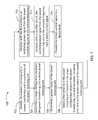
- FIG. 7is a flowchart illustrating steps in a method 700 for managing, from a power receiving unit, a power transfer from a power transferring unit, according to some embodiments.
- the PRUprovides the transferred power to charge or re-charge a battery (e.g., battery 170 ).
- Method 700may be performed at least partially by any one of MCC circuits installed in the PRU device, executing instructions stored in a memory (e.g., MCC 36 , and MCC 100 and memory 155 ), while communicating with each other through a communications circuit (e.g., communications circuit 38 , and 138 ).
- method 700is partially performed by a PTU in communication with one or more PRU's roaming in the proximity of the PTU.
- Each of the one or more PRU'smay be handled by a user having access authorization to a power charging service of the PTU.
- Methods consistent with the present disclosuremay include at least some, but not all of the steps illustrated in method 700 , performed in a different sequence. Furthermore, methods consistent with the present disclosure may include at least two or more steps as in method 700 performed overlapping in time, or almost simultaneously.
- Step 702includes identifying, by the PRU, a PTU in proximity of the PRU.
- Step 704includes determining a range configuration between the PTU and the PRU. In some embodiments, step 704 includes determining whether the PRU is in a near field range or in a far range of the PTU. In some embodiments, step 704 includes determining a geolocation of the PRU from the communication circuit in the PRU. Further, in some embodiments step 704 may include determining that the PRU is in the near field range when the PRU is within a few millimeters (mm), e.g., 2 mm, 3 mm, or less than 5 or 10 mm.
- mmmillimeters
- step 704may include determining that the PRU is in the far field range of the PTU when the PRU is within a few meters (m) of the PTU (e.g., 1 m, 2 m, or 5 to 10 m).
- the near field rangecan extend further distances, such as 6-8 inches (e.g., about 15-40 cm), depending on power transfer efficiency and safety considerations.
- a far field rangemay include distances of about 1-2 meters, or 3-12 meters.
- efficient RF power transfercan be achieved from 1-12 meters in a far field range.
- Step 706includes determining the power status the power receiving unit.
- step 706may include receiving a charge percentage of a battery in the PRU (e.g., 10%, 50%, or 100% and the like).
- step 706may also include receiving a “time remaining” for the operation of the PRU based on the power status, current usage conditions, and other environmental factors (e.g., temperature and the like). For example, in some embodiments step 706 may include receiving from the PRU a message as “10 minutes (min) remaining,” “5 min. remaining,” and the like.
- Step 708includes selecting a first antenna in the PRU based on the range configuration between the PTU and the PRU, and on the power status of the PRU.
- step 708includes selecting a radio-frequency antenna to receive a directed radio-frequency power when the range configuration between the power transferring unit and the power receiving unit is within a far field, and selecting an inductively coupled antenna when the range configuration between the power transferring unit and the power receiving unit is within a near field.
- step 708may also include selecting a radio-frequency antenna configured to receive a propagating, directed radio-frequency signal as the oscillating power signal when the range configuration between the power transferring unit and the power receiving unit is beyond a near field configuration and within a far field configuration.
- step 708includes simultaneously selecting a radio-frequency antenna configured to receive a propagating, directed radio-frequency signal and an inductively coupled antenna, when the range configuration between the power transferring unit and the power receiving unit is within a near field configuration.
- Step 710includes receiving, with the first antenna, an oscillating power signal from the power transferring unit at the selected frequency.
- step 710includes receiving, in the PRU and based on the power status information, a directed power signal from the PTU when the PRU is in proximity of a far range of the PTU.
- step 710includes receiving, in the PRU and based on the power status information, an inductively coupled field from the PTU that is resonant with the PRU, when the PRU is in the proximity of at least a near field range of the power transferring unit.
- the inductively coupled fieldis a RF-modulated magnetic field
- step 710includes receiving the resonant RF-modulated magnetic field with a receiver circuit in the PRU (e.g., Rx resonator 160 r , see FIG. 2 ).
- step 710includes receiving, in a wireless receiver, multiple wireless signals operating at multiple frequencies, and tuning the at least one power receiving circuit at a frequency of one of the wireless signals.
- Step 712includes converting, with a rectifier circuit, the oscillating power signal from the PTU at the selected frequency into a direct-current signal.
- step 712includes tuning a radio-frequency amplifier circuit coupled to the first antenna at the selected frequency in the power receiving unit.
- step 712includes balancing a differential input from the first antenna.
- step 712includes converting, in a rectifier circuit, one of multiple wireless signals into the direct-current signal.
- Step 714includes providing the direct-current signal to a device load.
- step 714includes receiving, in a reserve battery, at least a first portion of the direct-current signal, and providing at least a second portion of the direct-current signal from the reserve battery to a mobile electronic device docked in the power receiving unit.
- ASICsApplication Specific Integrated Circuits
- FPGAsField Programmable Gate Arrays
- DSPsdigital signal processors
- GPSsGeneral Purpose Processors
- MCUsMicrocontroller Units
- Examples of a signal bearing mediuminclude, but are not limited to, the following: a recordable type medium such as a floppy disk, a hard disk drive, a Compact Disc (CD), a Digital Video Disk (DVD), a digital tape, a computer memory, etc.; and a transmission type medium such as a digital and/or an analog communication medium, e.g., a fiber optic cable, a waveguide, a wired communication link, a wireless communication link (e.g., transmitter, receiver, transmission logic, reception logic, etc.).
- a recordable type mediumsuch as a floppy disk, a hard disk drive, a Compact Disc (CD), a Digital Video Disk (DVD), a digital tape, a computer memory, etc.
- a transmission type mediumsuch as a digital and/or an analog communication medium, e.g., a fiber optic cable, a waveguide, a wired communication link, a wireless communication link (e.g., transmitter, receiver, transmission logic, reception logic
- an implementermay opt for a mainly hardware and/or firmware vehicle; alternatively, if flexibility is paramount, the implementer may opt for a mainly software implementation; or, yet again alternatively, the implementer may opt for some combination of hardware, software, and/or firmware.
- any vehicle to be utilizedis a choice dependent upon the context in which the vehicle will be deployed and the specific concerns (e.g., speed, flexibility, or predictability) of the implementer, any of which may vary.
- Those skilled in the artwill recognize that optical aspects of implementations will typically employ optically-oriented hardware, software, and or firmware.
- machine-readable storage mediumor “computer readable medium” as used herein refers to any medium or media that participates in providing instructions or data to processor for execution. Such a medium may take many forms, including, but not limited to, non-volatile media, volatile media, and transmission media.
- Non-volatile mediainclude, for example, optical disks, magnetic disks, or flash memory (e.g., memory 155 ).
- Volatile mediainclude dynamic memory (e.g., memory 155 ).
- Transmission mediainclude coaxial cables, copper wire, and fiber optics, including the wires that comprise a bus.
- machine-readable mediainclude, for example, floppy disk, a flexible disk, hard disk, magnetic tape, any other magnetic medium, a CD-ROM, DVD, any other optical medium, punch cards, paper tape, any other physical medium with patterns of holes, a RAM, a PROM, an EPROM, a FLASH EPROM, any other memory chip or cartridge, or any other medium from which a computer can read.
- the machine-readable storage mediumcan be a machine-readable storage device, a machine-readable storage substrate, a memory device, a composition of matter effecting a machine-readable propagated signal, or a combination of one or more of them.
- a methodmay be an operation, an instruction, or a function and vice versa.
- a clause or a claimmay be amended to include some or all of the words (e.g., instructions, operations, functions, or components) recited in other one or more clauses, one or more words, one or more sentences, one or more phrases, one or more paragraphs, and/or one or more claims.
- phrases such as an aspect, the aspect, another aspect, some aspects, one or more aspects, an implementation, the implementation, another implementation, some implementations, one or more implementations, an embodiment, the embodiment, another embodiment, some embodiments, one or more embodiments, a configuration, the configuration, another configuration, some configurations, one or more configurations, the subject technology, the disclosure, the present disclosure, other variations thereof and alikeare for convenience and do not imply that a disclosure relating to such phrase(s) is essential to the subject technology or that such disclosure applies to all configurations of the subject technology.
- a disclosure relating to such phrase(s)may apply to all configurations, or one or more configurations.
- a disclosure relating to such phrase(s)may provide one or more examples.
- a phrase such as an aspect or some aspectsmay refer to one or more aspects and vice versa, and this applies similarly to other foregoing phrases.
Landscapes
- Engineering & Computer Science (AREA)
- Computer Networks & Wireless Communication (AREA)
- Power Engineering (AREA)
- Signal Processing (AREA)
- Physics & Mathematics (AREA)
- Electromagnetism (AREA)
- Charge And Discharge Circuits For Batteries Or The Like (AREA)
Abstract
Description
Claims (20)
Priority Applications (1)
| Application Number | Priority Date | Filing Date | Title |
|---|---|---|---|
| US15/786,506US10483806B2 (en) | 2016-10-18 | 2017-10-17 | Multi-mode energy receiver system |
Applications Claiming Priority (4)
| Application Number | Priority Date | Filing Date | Title |
|---|---|---|---|
| US201662409806P | 2016-10-18 | 2016-10-18 | |
| US201662409811P | 2016-10-18 | 2016-10-18 | |
| US201662409802P | 2016-10-18 | 2016-10-18 | |
| US15/786,506US10483806B2 (en) | 2016-10-18 | 2017-10-17 | Multi-mode energy receiver system |
Publications (2)
| Publication Number | Publication Date |
|---|---|
| US20180109147A1 US20180109147A1 (en) | 2018-04-19 |
| US10483806B2true US10483806B2 (en) | 2019-11-19 |
Family
ID=60191555
Family Applications (3)
| Application Number | Title | Priority Date | Filing Date |
|---|---|---|---|
| US15/786,503Expired - Fee RelatedUS10547211B2 (en) | 2016-10-18 | 2017-10-17 | Intelligent multi-mode wireless power transmitter system |
| US15/786,506Expired - Fee RelatedUS10483806B2 (en) | 2016-10-18 | 2017-10-17 | Multi-mode energy receiver system |
| US15/786,509AbandonedUS20180109148A1 (en) | 2016-10-18 | 2017-10-17 | Multi-mode wirelessly rechargeable battery system |
Family Applications Before (1)
| Application Number | Title | Priority Date | Filing Date |
|---|---|---|---|
| US15/786,503Expired - Fee RelatedUS10547211B2 (en) | 2016-10-18 | 2017-10-17 | Intelligent multi-mode wireless power transmitter system |
Family Applications After (1)
| Application Number | Title | Priority Date | Filing Date |
|---|---|---|---|
| US15/786,509AbandonedUS20180109148A1 (en) | 2016-10-18 | 2017-10-17 | Multi-mode wirelessly rechargeable battery system |
Country Status (2)
| Country | Link |
|---|---|
| US (3) | US10547211B2 (en) |
| WO (1) | WO2018075542A1 (en) |
Families Citing this family (14)
| Publication number | Priority date | Publication date | Assignee | Title |
|---|---|---|---|---|
| US10165531B1 (en)* | 2015-12-17 | 2018-12-25 | Spearlx Technologies, Inc. | Transmission and reception of signals in a time synchronized wireless sensor actuator network |
| US10547211B2 (en)* | 2016-10-18 | 2020-01-28 | Powersphyr Inc. | Intelligent multi-mode wireless power transmitter system |
| US20180328903A1 (en)* | 2017-05-12 | 2018-11-15 | Qualcomm Incorporated | Multi-power source perishable item sensor apparatus |
| CN108683512A (en)* | 2018-05-25 | 2018-10-19 | 英业达科技有限公司 | Telecommunication transmitting device, telecommunication transmission method and Intelligent lamp system |
| CN109755748B (en)* | 2019-01-21 | 2021-09-14 | 联想(北京)有限公司 | Electronic device |
| US11303160B2 (en)* | 2019-05-28 | 2022-04-12 | The University Of North Dakota | Wireless power transfer and wireless communications between two electronic components |
| WO2020246067A1 (en)* | 2019-06-03 | 2020-12-10 | 株式会社村田製作所 | Power receiving device of wireless power supply system and electronic equipment |
| US11258480B2 (en)* | 2020-03-31 | 2022-02-22 | Nxp B.V. | System and method of optimized backup functionality for electronic control key |
| US20210393968A1 (en)* | 2020-06-19 | 2021-12-23 | Medtronic, Inc. | Radio frequency energy harvesting |
| US20220181916A1 (en)* | 2020-12-09 | 2022-06-09 | Energous Corporation | Wireless-Power Transmitters With Antenna Elements Having Multiple Power-Transfer Points That Each Only Transfer Electromagnetic Energy Upon Coupling With A Wireless-Power Receiver, And Methods Of Use Thereof |
| KR20220149295A (en)* | 2021-04-30 | 2022-11-08 | 삼성전자주식회사 | Method for controlling a type of wireless charging and method thereof |
| US11916398B2 (en) | 2021-12-29 | 2024-02-27 | Energous Corporation | Small form-factor devices with integrated and modular harvesting receivers, and shelving-mounted wireless-power transmitters for use therewith |
| US12142939B2 (en) | 2022-05-13 | 2024-11-12 | Energous Corporation | Integrated wireless-power-transmission platform designed to operate in multiple bands, and multi-band antennas for use therewith |
| WO2025151335A1 (en)* | 2024-01-08 | 2025-07-17 | Dolby Intellectual Property Licensing, Llc | Energy storage for a power receiver of a wireless power system |
Citations (87)
| Publication number | Priority date | Publication date | Assignee | Title |
|---|---|---|---|---|
| US6289237B1 (en) | 1998-12-22 | 2001-09-11 | University Of Pittsburgh Of The Commonwealth System Of Higher Education | Apparatus for energizing a remote station and related method |
| US6615074B2 (en) | 1998-12-22 | 2003-09-02 | University Of Pittsburgh Of The Commonwealth System Of Higher Education | Apparatus for energizing a remote station and related method |
| US20040150934A1 (en) | 2003-02-04 | 2004-08-05 | Baarman David W. | Adapter |
| US6856291B2 (en) | 2002-08-15 | 2005-02-15 | University Of Pittsburgh- Of The Commonwealth System Of Higher Education | Energy harvesting circuits and associated methods |
| US6886685B2 (en) | 2002-07-16 | 2005-05-03 | Robert Slater | Stationery article for carrying self-stick note pads |
| US20050206577A1 (en) | 2004-03-17 | 2005-09-22 | Arcadyan Technology Corporation | Antenna apparatus having a reflector |
| US7027311B2 (en) | 2003-10-17 | 2006-04-11 | Firefly Power Technologies, Inc. | Method and apparatus for a wireless power supply |
| US7057514B2 (en) | 2003-06-02 | 2006-06-06 | University Of Pittsburgh - Of The Commonwealth System Oif Higher Education | Antenna on a wireless untethered device such as a chip or printed circuit board for harvesting energy from space |
| US20080054638A1 (en) | 2006-09-01 | 2008-03-06 | Powercast Corporation | Hybrid power harvesting and method |
| US7639994B2 (en) | 2006-07-29 | 2009-12-29 | Powercast Corporation | RF power transmission network and method |
| US20100127660A1 (en) | 2008-08-19 | 2010-05-27 | Qualcomm Incorporated | Wireless power transmission for portable wireless power charging |
| US7741734B2 (en) | 2005-07-12 | 2010-06-22 | Massachusetts Institute Of Technology | Wireless non-radiative energy transfer |
| US20100190436A1 (en) | 2008-08-26 | 2010-07-29 | Qualcomm Incorporated | Concurrent wireless power transmission and near-field communication |
| US20100244576A1 (en) | 2009-03-25 | 2010-09-30 | Qualcomm Incorporated | Optimization of wireless power devices |
| US7812771B2 (en) | 2006-03-22 | 2010-10-12 | Powercast, Llc | Method and apparatus for implementation of a wireless power supply |
| US7825543B2 (en) | 2005-07-12 | 2010-11-02 | Massachusetts Institute Of Technology | Wireless energy transfer |
| US7844306B2 (en) | 2005-05-24 | 2010-11-30 | Powercast Corporation | Power transmission network |
| US7868482B2 (en) | 2005-10-24 | 2011-01-11 | Powercast Corporation | Method and apparatus for high efficiency rectification for various loads |
| US7898105B2 (en) | 2006-09-01 | 2011-03-01 | Powercast Corporation | RF powered specialty lighting, motion, sound |
| US7925308B2 (en) | 2005-11-21 | 2011-04-12 | Powercast Corporation | Radio-frequency (RF) power portal |
| USD636333S1 (en) | 2010-09-23 | 2011-04-19 | Witricity Corporation | Wireless power source |
| US8035255B2 (en) | 2008-09-27 | 2011-10-11 | Witricity Corporation | Wireless energy transfer using planar capacitively loaded conducting loop resonators |
| EP2387127A2 (en) | 2010-05-14 | 2011-11-16 | Samsung Electronics Co., Ltd. | Method and apparatus for transmitting power and data |
| US8076801B2 (en) | 2008-05-14 | 2011-12-13 | Massachusetts Institute Of Technology | Wireless energy transfer, including interference enhancement |
| US8115448B2 (en) | 2007-06-01 | 2012-02-14 | Michael Sasha John | Systems and methods for wireless power |
| US20120062358A1 (en) | 2010-09-09 | 2012-03-15 | Nxp B.V. | Multiple-frequency solutions for remote access systems |
| US8159364B2 (en) | 2007-06-14 | 2012-04-17 | Omnilectric, Inc. | Wireless power transmission system |
| US8304935B2 (en) | 2008-09-27 | 2012-11-06 | Witricity Corporation | Wireless energy transfer using field shaping to reduce loss |
| US8324759B2 (en) | 2008-09-27 | 2012-12-04 | Witricity Corporation | Wireless energy transfer using magnetic materials to shape field and reduce loss |
| US8362651B2 (en) | 2008-10-01 | 2013-01-29 | Massachusetts Institute Of Technology | Efficient near-field wireless energy transfer using adiabatic system variations |
| US20130026981A1 (en) | 2011-07-28 | 2013-01-31 | Broadcom Corporation | Dual mode wireless power |
| US8378522B2 (en) | 2007-03-02 | 2013-02-19 | Qualcomm, Incorporated | Maximizing power yield from wireless power magnetic resonators |
| US8400017B2 (en) | 2008-09-27 | 2013-03-19 | Witricity Corporation | Wireless energy transfer for computer peripheral applications |
| US8410636B2 (en) | 2008-09-27 | 2013-04-02 | Witricity Corporation | Low AC resistance conductor designs |
| EP2579424A2 (en) | 2011-10-04 | 2013-04-10 | Samsung Electronics Co., Ltd | Wireless power multi-charging method and power transmitter |
| US8441154B2 (en) | 2008-09-27 | 2013-05-14 | Witricity Corporation | Multi-resonator wireless energy transfer for exterior lighting |
| US8446248B2 (en) | 2007-06-14 | 2013-05-21 | Omnilectric, Inc. | Wireless power transmission system |
| US8461720B2 (en) | 2008-09-27 | 2013-06-11 | Witricity Corporation | Wireless energy transfer using conducting surfaces to shape fields and reduce loss |
| US8461817B2 (en) | 2007-09-11 | 2013-06-11 | Powercast Corporation | Method and apparatus for providing wireless power to a load device |
| US8461721B2 (en) | 2008-09-27 | 2013-06-11 | Witricity Corporation | Wireless energy transfer using object positioning for low loss |
| US8461722B2 (en) | 2008-09-27 | 2013-06-11 | Witricity Corporation | Wireless energy transfer using conducting surfaces to shape field and improve K |
| US8466583B2 (en) | 2008-09-27 | 2013-06-18 | Witricity Corporation | Tunable wireless energy transfer for outdoor lighting applications |
| US8471410B2 (en) | 2008-09-27 | 2013-06-25 | Witricity Corporation | Wireless energy transfer over distance using field shaping to improve the coupling factor |
| US8476788B2 (en) | 2008-09-27 | 2013-07-02 | Witricity Corporation | Wireless energy transfer with high-Q resonators using field shaping to improve K |
| US8482158B2 (en) | 2008-09-27 | 2013-07-09 | Witricity Corporation | Wireless energy transfer using variable size resonators and system monitoring |
| US8487480B1 (en) | 2008-09-27 | 2013-07-16 | Witricity Corporation | Wireless energy transfer resonator kit |
| US8497601B2 (en) | 2008-09-27 | 2013-07-30 | Witricity Corporation | Wireless energy transfer converters |
| US20130221915A1 (en) | 2012-02-28 | 2013-08-29 | Samsung Electronics Co., Ltd. | Method and apparatus for wirelessly charging multiple wireless power receivers |
| US8552592B2 (en) | 2008-09-27 | 2013-10-08 | Witricity Corporation | Wireless energy transfer with feedback control for lighting applications |
| USD692010S1 (en) | 2012-11-09 | 2013-10-22 | Witricity Corporation | Wireless power source |
| US8587155B2 (en) | 2008-09-27 | 2013-11-19 | Witricity Corporation | Wireless energy transfer using repeater resonators |
| US8587153B2 (en) | 2008-09-27 | 2013-11-19 | Witricity Corporation | Wireless energy transfer using high Q resonators for lighting applications |
| US8598743B2 (en) | 2008-09-27 | 2013-12-03 | Witricity Corporation | Resonator arrays for wireless energy transfer |
| US8621245B2 (en) | 2005-06-08 | 2013-12-31 | Powercast Corporation | Powering devices using RF energy harvesting |
| USD697477S1 (en) | 2013-05-17 | 2014-01-14 | Witricity Corporation | Wireless pad charger |
| US8629578B2 (en) | 2008-09-27 | 2014-01-14 | Witricity Corporation | Wireless energy transfer systems |
| US8643326B2 (en) | 2008-09-27 | 2014-02-04 | Witricity Corporation | Tunable wireless energy transfer systems |
| US8667452B2 (en) | 2011-11-04 | 2014-03-04 | Witricity Corporation | Wireless energy transfer modeling tool |
| US8669676B2 (en) | 2008-09-27 | 2014-03-11 | Witricity Corporation | Wireless energy transfer across variable distances using field shaping with magnetic materials to improve the coupling factor |
| US8686598B2 (en) | 2008-09-27 | 2014-04-01 | Witricity Corporation | Wireless energy transfer for supplying power and heat to a device |
| US8692410B2 (en) | 2008-09-27 | 2014-04-08 | Witricity Corporation | Wireless energy transfer with frequency hopping |
| US8692412B2 (en) | 2008-09-27 | 2014-04-08 | Witricity Corporation | Temperature compensation in a wireless transfer system |
| US8723366B2 (en) | 2008-09-27 | 2014-05-13 | Witricity Corporation | Wireless energy transfer resonator enclosures |
| US8729737B2 (en) | 2008-09-27 | 2014-05-20 | Witricity Corporation | Wireless energy transfer using repeater resonators |
| USD705745S1 (en) | 2013-07-08 | 2014-05-27 | Witricity Corporation | Printed resonator coil |
| US8772973B2 (en) | 2008-09-27 | 2014-07-08 | Witricity Corporation | Integrated resonator-shield structures |
| EP2755300A1 (en) | 2011-09-09 | 2014-07-16 | The Chugoku Electric Power Co., Inc. | Non-contact power supply system and non-contact power supply method |
| USD709855S1 (en) | 2013-10-31 | 2014-07-29 | Witricity Corporation | Clock radio phone charger |
| US8847548B2 (en) | 2008-09-27 | 2014-09-30 | Witricity Corporation | Wireless energy transfer for implantable devices |
| US20140327323A1 (en) | 2011-12-27 | 2014-11-06 | The Chugoku Electric Power Co., Inc. | Wireless power transfer system, transmission device, and controlling method of wireless power transfer system |
| US8901779B2 (en) | 2008-09-27 | 2014-12-02 | Witricity Corporation | Wireless energy transfer with resonator arrays for medical applications |
| US8901778B2 (en) | 2008-09-27 | 2014-12-02 | Witricity Corporation | Wireless energy transfer with variable size resonators for implanted medical devices |
| US8907531B2 (en) | 2008-09-27 | 2014-12-09 | Witricity Corporation | Wireless energy transfer with variable size resonators for medical applications |
| US8928276B2 (en) | 2008-09-27 | 2015-01-06 | Witricity Corporation | Integrated repeaters for cell phone applications |
| US20150011160A1 (en) | 2013-07-08 | 2015-01-08 | Research In Motion Limited | Docking station connectivity monitor/controller |
| US8937408B2 (en) | 2008-09-27 | 2015-01-20 | Witricity Corporation | Wireless energy transfer for medical applications |
| USD722048S1 (en) | 2013-07-08 | 2015-02-03 | Witricity Corporation | Printed resonator coil |
| US8963488B2 (en) | 2008-09-27 | 2015-02-24 | Witricity Corporation | Position insensitive wireless charging |
| WO2015064815A1 (en) | 2013-10-31 | 2015-05-07 | 주식회사 한림포스텍 | Hybrid wireless power transmission system and method therefor |
| US9143000B2 (en) | 2012-07-06 | 2015-09-22 | Energous Corporation | Portable wireless charging pad |
| US9240824B2 (en) | 2009-02-13 | 2016-01-19 | Qualcomm Incorporated | Wireless power and wireless communication for electronic devices |
| US20160020637A1 (en) | 2014-07-15 | 2016-01-21 | Rf Micro Devices, Inc. | Wireless charging circuit |
| US20160285489A1 (en) | 2015-03-25 | 2016-09-29 | South University Of Science And Technology Of China | Receiver |
| US20160301257A1 (en) | 2015-04-07 | 2016-10-13 | University Of Washington | Multiband harvesting systems and methods including switching networks |
| WO2016164321A1 (en) | 2015-04-10 | 2016-10-13 | Ossia Inc. | Wirelessly chargeable battery apparatus |
| US9608472B2 (en) | 2009-12-25 | 2017-03-28 | Golba Llc | Method and apparatus for wirelessly transferring power and communicating with one or more slave devices |
| US20180109148A1 (en)* | 2016-10-18 | 2018-04-19 | Powersphyr Inc. | Multi-mode wirelessly rechargeable battery system |
Family Cites Families (12)
| Publication number | Priority date | Publication date | Assignee | Title |
|---|---|---|---|---|
| US7358913B2 (en)* | 1999-11-18 | 2008-04-15 | Automotive Systems Laboratory, Inc. | Multi-beam antenna |
| US6434372B1 (en)* | 2001-01-12 | 2002-08-13 | The Regents Of The University Of California | Long-range, full-duplex, modulated-reflector cell phone for voice/data transmission |
| KR100715420B1 (en)* | 2003-08-29 | 2007-05-09 | 후지쓰 텐 가부시키가이샤 | Circular polarization antenna and integrated antenna having the same |
| US8064533B2 (en)* | 2006-12-29 | 2011-11-22 | Broadcom Corporation | Reconfigurable MIMO transceiver and method for use therewith |
| US8965461B2 (en)* | 2008-05-13 | 2015-02-24 | Qualcomm Incorporated | Reverse link signaling via receive antenna impedance modulation |
| US9544683B2 (en)* | 2008-09-27 | 2017-01-10 | Witricity Corporation | Wirelessly powered audio devices |
| US8922969B2 (en)* | 2009-12-03 | 2014-12-30 | Goji Limited | Ferrite-induced spatial modification of EM field patterns |
| JP2014519798A (en)* | 2011-05-13 | 2014-08-14 | サムスン エレクトロニクス カンパニー リミテッド | Transmitter and receiver in wireless power transmission system, and wireless power transmission / reception method of said devices |
| US8942624B2 (en)* | 2012-03-30 | 2015-01-27 | Integrated Device Technology, Inc. | Apparatus, system, and method for back-channel communication in an inductive wireless power transfer system |
| US9735584B2 (en)* | 2013-10-17 | 2017-08-15 | Access Business Group International Llc | Wireless power communication |
| WO2016189492A1 (en)* | 2015-05-26 | 2016-12-01 | King Abdullah University Of Science And Technology | Rf-to-dc power converters for wireless powering |
| EP4007121A1 (en)* | 2016-05-27 | 2022-06-01 | WiTricity Corporation | Voltage regulation in wireless power receivers |
- 2017
- 2017-10-17USUS15/786,503patent/US10547211B2/ennot_activeExpired - Fee Related
- 2017-10-17USUS15/786,506patent/US10483806B2/ennot_activeExpired - Fee Related
- 2017-10-17USUS15/786,509patent/US20180109148A1/ennot_activeAbandoned
- 2017-10-17WOPCT/US2017/057015patent/WO2018075542A1/ennot_activeCeased
Patent Citations (121)
| Publication number | Priority date | Publication date | Assignee | Title |
|---|---|---|---|---|
| US6615074B2 (en) | 1998-12-22 | 2003-09-02 | University Of Pittsburgh Of The Commonwealth System Of Higher Education | Apparatus for energizing a remote station and related method |
| US6289237B1 (en) | 1998-12-22 | 2001-09-11 | University Of Pittsburgh Of The Commonwealth System Of Higher Education | Apparatus for energizing a remote station and related method |
| US6886685B2 (en) | 2002-07-16 | 2005-05-03 | Robert Slater | Stationery article for carrying self-stick note pads |
| US6856291B2 (en) | 2002-08-15 | 2005-02-15 | University Of Pittsburgh- Of The Commonwealth System Of Higher Education | Energy harvesting circuits and associated methods |
| US20040150934A1 (en) | 2003-02-04 | 2004-08-05 | Baarman David W. | Adapter |
| US7057514B2 (en) | 2003-06-02 | 2006-06-06 | University Of Pittsburgh - Of The Commonwealth System Oif Higher Education | Antenna on a wireless untethered device such as a chip or printed circuit board for harvesting energy from space |
| US7027311B2 (en) | 2003-10-17 | 2006-04-11 | Firefly Power Technologies, Inc. | Method and apparatus for a wireless power supply |
| US7643312B2 (en) | 2003-10-17 | 2010-01-05 | Powercast Corporation | Method and apparatus for a wireless power supply |
| US20050206577A1 (en) | 2004-03-17 | 2005-09-22 | Arcadyan Technology Corporation | Antenna apparatus having a reflector |
| US7844306B2 (en) | 2005-05-24 | 2010-11-30 | Powercast Corporation | Power transmission network |
| US8621245B2 (en) | 2005-06-08 | 2013-12-31 | Powercast Corporation | Powering devices using RF energy harvesting |
| US9021277B2 (en) | 2005-06-08 | 2015-04-28 | Powercast Corporation | Powering devices using RF energy harvesting |
| US8022576B2 (en) | 2005-07-12 | 2011-09-20 | Massachusetts Institute Of Technology | Wireless non-radiative energy transfer |
| US8395282B2 (en) | 2005-07-12 | 2013-03-12 | Massachusetts Institute Of Technology | Wireless non-radiative energy transfer |
| US8400020B2 (en) | 2005-07-12 | 2013-03-19 | Massachusetts Institute Of Technology | Wireless energy transfer with high-Q devices at variable distances |
| US8400024B2 (en) | 2005-07-12 | 2013-03-19 | Massachusetts Institute Of Technology | Wireless energy transfer across variable distances |
| US7825543B2 (en) | 2005-07-12 | 2010-11-02 | Massachusetts Institute Of Technology | Wireless energy transfer |
| US7741734B2 (en) | 2005-07-12 | 2010-06-22 | Massachusetts Institute Of Technology | Wireless non-radiative energy transfer |
| US8097983B2 (en) | 2005-07-12 | 2012-01-17 | Massachusetts Institute Of Technology | Wireless energy transfer |
| US8400019B2 (en) | 2005-07-12 | 2013-03-19 | Massachusetts Institute Of Technology | Wireless energy transfer with high-Q from more than one source |
| US8076800B2 (en) | 2005-07-12 | 2011-12-13 | Massachusetts Institute Of Technology | Wireless non-radiative energy transfer |
| US8791599B2 (en) | 2005-07-12 | 2014-07-29 | Massachusetts Institute Of Technology | Wireless energy transfer to a moving device between high-Q resonators |
| US8400018B2 (en) | 2005-07-12 | 2013-03-19 | Massachusetts Institute Of Technology | Wireless energy transfer with high-Q at high efficiency |
| US8772972B2 (en) | 2005-07-12 | 2014-07-08 | Massachusetts Institute Of Technology | Wireless energy transfer across a distance to a moving device |
| US8772971B2 (en) | 2005-07-12 | 2014-07-08 | Massachusetts Institute Of Technology | Wireless energy transfer across variable distances with high-Q capacitively-loaded conducting-wire loops |
| US8766485B2 (en) | 2005-07-12 | 2014-07-01 | Massachusetts Institute Of Technology | Wireless energy transfer over distances to a moving device |
| US8400021B2 (en) | 2005-07-12 | 2013-03-19 | Massachusetts Institute Of Technology | Wireless energy transfer with high-Q sub-wavelength resonators |
| US8395283B2 (en) | 2005-07-12 | 2013-03-12 | Massachusetts Institute Of Technology | Wireless energy transfer over a distance at high efficiency |
| US8400022B2 (en) | 2005-07-12 | 2013-03-19 | Massachusetts Institute Of Technology | Wireless energy transfer with high-Q similar resonant frequency resonators |
| US8400023B2 (en) | 2005-07-12 | 2013-03-19 | Massachusetts Institute Of Technology | Wireless energy transfer with high-Q capacitively loaded conducting loops |
| US8760007B2 (en) | 2005-07-12 | 2014-06-24 | Massachusetts Institute Of Technology | Wireless energy transfer with high-Q to more than one device |
| US8760008B2 (en) | 2005-07-12 | 2014-06-24 | Massachusetts Institute Of Technology | Wireless energy transfer over variable distances between resonators of substantially similar resonant frequencies |
| US8084889B2 (en) | 2005-07-12 | 2011-12-27 | Massachusetts Institute Of Technology | Wireless non-radiative energy transfer |
| US9000616B2 (en) | 2005-10-24 | 2015-04-07 | Powercast Corporation | Method and apparatus for high efficiency rectification for various loads |
| US7868482B2 (en) | 2005-10-24 | 2011-01-11 | Powercast Corporation | Method and apparatus for high efficiency rectification for various loads |
| US7925308B2 (en) | 2005-11-21 | 2011-04-12 | Powercast Corporation | Radio-frequency (RF) power portal |
| US7812771B2 (en) | 2006-03-22 | 2010-10-12 | Powercast, Llc | Method and apparatus for implementation of a wireless power supply |
| US7639994B2 (en) | 2006-07-29 | 2009-12-29 | Powercast Corporation | RF power transmission network and method |
| US8432062B2 (en) | 2006-09-01 | 2013-04-30 | Powercast Corporation | RF powered specialty lighting, motion, sound |
| US20080054638A1 (en) | 2006-09-01 | 2008-03-06 | Powercast Corporation | Hybrid power harvesting and method |
| US8159090B2 (en) | 2006-09-01 | 2012-04-17 | Powercast Corporation | Hybrid power harvesting and method |
| US7898105B2 (en) | 2006-09-01 | 2011-03-01 | Powercast Corporation | RF powered specialty lighting, motion, sound |
| US8378522B2 (en) | 2007-03-02 | 2013-02-19 | Qualcomm, Incorporated | Maximizing power yield from wireless power magnetic resonators |
| US8115448B2 (en) | 2007-06-01 | 2012-02-14 | Michael Sasha John | Systems and methods for wireless power |
| US8805530B2 (en) | 2007-06-01 | 2014-08-12 | Witricity Corporation | Power generation for implantable devices |
| US8159364B2 (en) | 2007-06-14 | 2012-04-17 | Omnilectric, Inc. | Wireless power transmission system |
| US9142973B2 (en) | 2007-06-14 | 2015-09-22 | Ossia, Inc. | Wireless power transmission system |
| US8410953B2 (en) | 2007-06-14 | 2013-04-02 | Omnilectric, Inc. | Wireless power transmission system |
| US8854176B2 (en) | 2007-06-14 | 2014-10-07 | Ossia, Inc. | Wireless power transmission system |
| US8446248B2 (en) | 2007-06-14 | 2013-05-21 | Omnilectric, Inc. | Wireless power transmission system |
| US8558661B2 (en) | 2007-06-14 | 2013-10-15 | Omnilectric, Inc. | Wireless power transmission system |
| US8461817B2 (en) | 2007-09-11 | 2013-06-11 | Powercast Corporation | Method and apparatus for providing wireless power to a load device |
| US8076801B2 (en) | 2008-05-14 | 2011-12-13 | Massachusetts Institute Of Technology | Wireless energy transfer, including interference enhancement |
| US20100127660A1 (en) | 2008-08-19 | 2010-05-27 | Qualcomm Incorporated | Wireless power transmission for portable wireless power charging |
| US20100190436A1 (en) | 2008-08-26 | 2010-07-29 | Qualcomm Incorporated | Concurrent wireless power transmission and near-field communication |
| US8716903B2 (en) | 2008-09-27 | 2014-05-06 | Witricity Corporation | Low AC resistance conductor designs |
| US8928276B2 (en) | 2008-09-27 | 2015-01-06 | Witricity Corporation | Integrated repeaters for cell phone applications |
| US8461719B2 (en) | 2008-09-27 | 2013-06-11 | Witricity Corporation | Wireless energy transfer systems |
| US8461722B2 (en) | 2008-09-27 | 2013-06-11 | Witricity Corporation | Wireless energy transfer using conducting surfaces to shape field and improve K |
| US8466583B2 (en) | 2008-09-27 | 2013-06-18 | Witricity Corporation | Tunable wireless energy transfer for outdoor lighting applications |
| US8471410B2 (en) | 2008-09-27 | 2013-06-25 | Witricity Corporation | Wireless energy transfer over distance using field shaping to improve the coupling factor |
| US8476788B2 (en) | 2008-09-27 | 2013-07-02 | Witricity Corporation | Wireless energy transfer with high-Q resonators using field shaping to improve K |
| US8482158B2 (en) | 2008-09-27 | 2013-07-09 | Witricity Corporation | Wireless energy transfer using variable size resonators and system monitoring |
| US8487480B1 (en) | 2008-09-27 | 2013-07-16 | Witricity Corporation | Wireless energy transfer resonator kit |
| US8497601B2 (en) | 2008-09-27 | 2013-07-30 | Witricity Corporation | Wireless energy transfer converters |
| US8410636B2 (en) | 2008-09-27 | 2013-04-02 | Witricity Corporation | Low AC resistance conductor designs |
| US8552592B2 (en) | 2008-09-27 | 2013-10-08 | Witricity Corporation | Wireless energy transfer with feedback control for lighting applications |
| US8461720B2 (en) | 2008-09-27 | 2013-06-11 | Witricity Corporation | Wireless energy transfer using conducting surfaces to shape fields and reduce loss |
| US8963488B2 (en) | 2008-09-27 | 2015-02-24 | Witricity Corporation | Position insensitive wireless charging |
| US8587155B2 (en) | 2008-09-27 | 2013-11-19 | Witricity Corporation | Wireless energy transfer using repeater resonators |
| US8587153B2 (en) | 2008-09-27 | 2013-11-19 | Witricity Corporation | Wireless energy transfer using high Q resonators for lighting applications |
| US8598743B2 (en) | 2008-09-27 | 2013-12-03 | Witricity Corporation | Resonator arrays for wireless energy transfer |
| US8324759B2 (en) | 2008-09-27 | 2012-12-04 | Witricity Corporation | Wireless energy transfer using magnetic materials to shape field and reduce loss |
| US8618696B2 (en) | 2008-09-27 | 2013-12-31 | Witricity Corporation | Wireless energy transfer systems |
| US8937408B2 (en) | 2008-09-27 | 2015-01-20 | Witricity Corporation | Wireless energy transfer for medical applications |
| US8629578B2 (en) | 2008-09-27 | 2014-01-14 | Witricity Corporation | Wireless energy transfer systems |
| US8643326B2 (en) | 2008-09-27 | 2014-02-04 | Witricity Corporation | Tunable wireless energy transfer systems |
| US8461721B2 (en) | 2008-09-27 | 2013-06-11 | Witricity Corporation | Wireless energy transfer using object positioning for low loss |
| US8669676B2 (en) | 2008-09-27 | 2014-03-11 | Witricity Corporation | Wireless energy transfer across variable distances using field shaping with magnetic materials to improve the coupling factor |
| US8686598B2 (en) | 2008-09-27 | 2014-04-01 | Witricity Corporation | Wireless energy transfer for supplying power and heat to a device |
| US8692410B2 (en) | 2008-09-27 | 2014-04-08 | Witricity Corporation | Wireless energy transfer with frequency hopping |
| US8692412B2 (en) | 2008-09-27 | 2014-04-08 | Witricity Corporation | Temperature compensation in a wireless transfer system |
| US8400017B2 (en) | 2008-09-27 | 2013-03-19 | Witricity Corporation | Wireless energy transfer for computer peripheral applications |
| US8723366B2 (en) | 2008-09-27 | 2014-05-13 | Witricity Corporation | Wireless energy transfer resonator enclosures |
| US8729737B2 (en) | 2008-09-27 | 2014-05-20 | Witricity Corporation | Wireless energy transfer using repeater resonators |
| US8907531B2 (en) | 2008-09-27 | 2014-12-09 | Witricity Corporation | Wireless energy transfer with variable size resonators for medical applications |
| US8304935B2 (en) | 2008-09-27 | 2012-11-06 | Witricity Corporation | Wireless energy transfer using field shaping to reduce loss |
| US8901778B2 (en) | 2008-09-27 | 2014-12-02 | Witricity Corporation | Wireless energy transfer with variable size resonators for implanted medical devices |
| US8441154B2 (en) | 2008-09-27 | 2013-05-14 | Witricity Corporation | Multi-resonator wireless energy transfer for exterior lighting |
| US8901779B2 (en) | 2008-09-27 | 2014-12-02 | Witricity Corporation | Wireless energy transfer with resonator arrays for medical applications |
| US8035255B2 (en) | 2008-09-27 | 2011-10-11 | Witricity Corporation | Wireless energy transfer using planar capacitively loaded conducting loop resonators |
| US8772973B2 (en) | 2008-09-27 | 2014-07-08 | Witricity Corporation | Integrated resonator-shield structures |
| US8847548B2 (en) | 2008-09-27 | 2014-09-30 | Witricity Corporation | Wireless energy transfer for implantable devices |
| US8836172B2 (en) | 2008-10-01 | 2014-09-16 | Massachusetts Institute Of Technology | Efficient near-field wireless energy transfer using adiabatic system variations |
| US8362651B2 (en) | 2008-10-01 | 2013-01-29 | Massachusetts Institute Of Technology | Efficient near-field wireless energy transfer using adiabatic system variations |
| US9240824B2 (en) | 2009-02-13 | 2016-01-19 | Qualcomm Incorporated | Wireless power and wireless communication for electronic devices |
| US20100244576A1 (en) | 2009-03-25 | 2010-09-30 | Qualcomm Incorporated | Optimization of wireless power devices |
| US9608472B2 (en) | 2009-12-25 | 2017-03-28 | Golba Llc | Method and apparatus for wirelessly transferring power and communicating with one or more slave devices |
| EP2387127A2 (en) | 2010-05-14 | 2011-11-16 | Samsung Electronics Co., Ltd. | Method and apparatus for transmitting power and data |
| US20120062358A1 (en) | 2010-09-09 | 2012-03-15 | Nxp B.V. | Multiple-frequency solutions for remote access systems |
| USD636333S1 (en) | 2010-09-23 | 2011-04-19 | Witricity Corporation | Wireless power source |
| US20130026981A1 (en) | 2011-07-28 | 2013-01-31 | Broadcom Corporation | Dual mode wireless power |
| EP2755300A1 (en) | 2011-09-09 | 2014-07-16 | The Chugoku Electric Power Co., Inc. | Non-contact power supply system and non-contact power supply method |
| EP2579424A2 (en) | 2011-10-04 | 2013-04-10 | Samsung Electronics Co., Ltd | Wireless power multi-charging method and power transmitter |
| US8875086B2 (en) | 2011-11-04 | 2014-10-28 | Witricity Corporation | Wireless energy transfer modeling tool |
| US8667452B2 (en) | 2011-11-04 | 2014-03-04 | Witricity Corporation | Wireless energy transfer modeling tool |
| US20140327323A1 (en) | 2011-12-27 | 2014-11-06 | The Chugoku Electric Power Co., Inc. | Wireless power transfer system, transmission device, and controlling method of wireless power transfer system |
| US20130221915A1 (en) | 2012-02-28 | 2013-08-29 | Samsung Electronics Co., Ltd. | Method and apparatus for wirelessly charging multiple wireless power receivers |
| US9143000B2 (en) | 2012-07-06 | 2015-09-22 | Energous Corporation | Portable wireless charging pad |
| USD692010S1 (en) | 2012-11-09 | 2013-10-22 | Witricity Corporation | Wireless power source |
| USD697477S1 (en) | 2013-05-17 | 2014-01-14 | Witricity Corporation | Wireless pad charger |
| US20150011160A1 (en) | 2013-07-08 | 2015-01-08 | Research In Motion Limited | Docking station connectivity monitor/controller |
| USD722048S1 (en) | 2013-07-08 | 2015-02-03 | Witricity Corporation | Printed resonator coil |
| USD705745S1 (en) | 2013-07-08 | 2014-05-27 | Witricity Corporation | Printed resonator coil |
| WO2015064815A1 (en) | 2013-10-31 | 2015-05-07 | 주식회사 한림포스텍 | Hybrid wireless power transmission system and method therefor |
| USD709855S1 (en) | 2013-10-31 | 2014-07-29 | Witricity Corporation | Clock radio phone charger |
| US20160020637A1 (en) | 2014-07-15 | 2016-01-21 | Rf Micro Devices, Inc. | Wireless charging circuit |
| US20160285489A1 (en) | 2015-03-25 | 2016-09-29 | South University Of Science And Technology Of China | Receiver |
| US20160301257A1 (en) | 2015-04-07 | 2016-10-13 | University Of Washington | Multiband harvesting systems and methods including switching networks |
| WO2016164321A1 (en) | 2015-04-10 | 2016-10-13 | Ossia Inc. | Wirelessly chargeable battery apparatus |
| US20180109148A1 (en)* | 2016-10-18 | 2018-04-19 | Powersphyr Inc. | Multi-mode wirelessly rechargeable battery system |
Non-Patent Citations (3)
| Title |
|---|
| International Search Report & Written Opinion for PCT Application PCT/US2017/026186 dated Jul. 14, 2017, 17 pages. |
| International Search Report & Written Opinion for PCT Application PCT/US2017/057015 dated Jan. 18, 2018, 23 pages. |
| Jorgesen et al., "Balun Basics Primer: A Tutorial on Baluns, Balun Transfromers, Magic-Ts, and 180° Hybrids," Marki Microwave, Inc, 2014, 12 pages. |
Also Published As
| Publication number | Publication date |
|---|---|
| US20180109146A1 (en) | 2018-04-19 |
| WO2018075542A1 (en) | 2018-04-26 |
| US10547211B2 (en) | 2020-01-28 |
| US20180109148A1 (en) | 2018-04-19 |
| US20180109147A1 (en) | 2018-04-19 |
Similar Documents
| Publication | Publication Date | Title |
|---|---|---|
| US10483806B2 (en) | Multi-mode energy receiver system | |
| US10069328B2 (en) | Intelligent multi-mode wireless power system | |
| US8947041B2 (en) | Bidirectional wireless power transmission | |
| CN103733535B (en) | Wireless Power Receiver with Multiple Receiver Coils | |
| JP5628191B2 (en) | Retrofitting wireless power and near field communication in electronic devices | |
| JP6030305B2 (en) | Wireless power transfer for portable enclosures | |
| US8541974B2 (en) | Movable magnetically resonant antenna for wireless charging | |
| US8810194B2 (en) | Retrofitting wireless power and near-field communication in electronic devices | |
| JP6069256B2 (en) | Variable wireless power transmission | |
| KR101247436B1 (en) | Concurrent wireless power transmission and near-field communication | |
| EP2394349B1 (en) | Wireless power for charging devices | |
| WO2017176908A1 (en) | Intelligent multi-mode wireless power transfer system | |
| EP3479457B1 (en) | Apparatus and method for wireless power charging of subsequent receiver | |
| CN103744492A (en) | Heat dissipation cushion for wireless charging notebook computer |
Legal Events
| Date | Code | Title | Description |
|---|---|---|---|
| FEPP | Fee payment procedure | Free format text:ENTITY STATUS SET TO UNDISCOUNTED (ORIGINAL EVENT CODE: BIG.); ENTITY STATUS OF PATENT OWNER: SMALL ENTITY | |
| AS | Assignment | Owner name:POWERSPHYR INC., CALIFORNIA Free format text:ASSIGNMENT OF ASSIGNORS INTEREST;ASSIGNORS:MENG, DAVID F.;WRIGHT, WILLIAM B.;SIGNING DATES FROM 20171015 TO 20171017;REEL/FRAME:043956/0638 | |
| FEPP | Fee payment procedure | Free format text:ENTITY STATUS SET TO SMALL (ORIGINAL EVENT CODE: SMAL); ENTITY STATUS OF PATENT OWNER: SMALL ENTITY | |
| STPP | Information on status: patent application and granting procedure in general | Free format text:DOCKETED NEW CASE - READY FOR EXAMINATION | |
| STPP | Information on status: patent application and granting procedure in general | Free format text:NON FINAL ACTION MAILED | |
| STPP | Information on status: patent application and granting procedure in general | Free format text:NOTICE OF ALLOWANCE MAILED -- APPLICATION RECEIVED IN OFFICE OF PUBLICATIONS | |
| STCF | Information on status: patent grant | Free format text:PATENTED CASE | |
| AS | Assignment | Owner name:KNOBBE, MARTENS, OLSON & BEAR, LLP, CALIFORNIA Free format text:SECURITY INTEREST;ASSIGNOR:POWERSPHYR INC.;REEL/FRAME:062183/0688 Effective date:20220926 | |
| FEPP | Fee payment procedure | Free format text:MAINTENANCE FEE REMINDER MAILED (ORIGINAL EVENT CODE: REM.); ENTITY STATUS OF PATENT OWNER: SMALL ENTITY | |
| LAPS | Lapse for failure to pay maintenance fees | Free format text:PATENT EXPIRED FOR FAILURE TO PAY MAINTENANCE FEES (ORIGINAL EVENT CODE: EXP.); ENTITY STATUS OF PATENT OWNER: SMALL ENTITY | |
| STCH | Information on status: patent discontinuation | Free format text:PATENT EXPIRED DUE TO NONPAYMENT OF MAINTENANCE FEES UNDER 37 CFR 1.362 | |
| FP | Lapsed due to failure to pay maintenance fee | Effective date:20231119 |