US10478202B2 - Shock wave valvuloplasty device with moveable shock wave generator - Google Patents
Shock wave valvuloplasty device with moveable shock wave generatorDownload PDFInfo
- Publication number
- US10478202B2 US10478202B2US15/729,238US201715729238AUS10478202B2US 10478202 B2US10478202 B2US 10478202B2US 201715729238 AUS201715729238 AUS 201715729238AUS 10478202 B2US10478202 B2US 10478202B2
- Authority
- US
- United States
- Prior art keywords
- electrode
- shock wave
- balloon
- wave generator
- valve
- Prior art date
- Legal status (The legal status is an assumption and is not a legal conclusion. Google has not performed a legal analysis and makes no representation as to the accuracy of the status listed.)
- Active, expires
Links
Images


Classifications
- A—HUMAN NECESSITIES
- A61—MEDICAL OR VETERINARY SCIENCE; HYGIENE
- A61B—DIAGNOSIS; SURGERY; IDENTIFICATION
- A61B17/00—Surgical instruments, devices or methods
- A61B17/22—Implements for squeezing-off ulcers or the like on inner organs of the body; Implements for scraping-out cavities of body organs, e.g. bones; for invasive removal or destruction of calculus using mechanical vibrations; for removing obstructions in blood vessels, not otherwise provided for
- A61B17/22004—Implements for squeezing-off ulcers or the like on inner organs of the body; Implements for scraping-out cavities of body organs, e.g. bones; for invasive removal or destruction of calculus using mechanical vibrations; for removing obstructions in blood vessels, not otherwise provided for using mechanical vibrations, e.g. ultrasonic shock waves
- A61B17/22012—Implements for squeezing-off ulcers or the like on inner organs of the body; Implements for scraping-out cavities of body organs, e.g. bones; for invasive removal or destruction of calculus using mechanical vibrations; for removing obstructions in blood vessels, not otherwise provided for using mechanical vibrations, e.g. ultrasonic shock waves in direct contact with, or very close to, the obstruction or concrement
- A61B17/22022—Implements for squeezing-off ulcers or the like on inner organs of the body; Implements for scraping-out cavities of body organs, e.g. bones; for invasive removal or destruction of calculus using mechanical vibrations; for removing obstructions in blood vessels, not otherwise provided for using mechanical vibrations, e.g. ultrasonic shock waves in direct contact with, or very close to, the obstruction or concrement using electric discharge
- A—HUMAN NECESSITIES
- A61—MEDICAL OR VETERINARY SCIENCE; HYGIENE
- A61B—DIAGNOSIS; SURGERY; IDENTIFICATION
- A61B17/00—Surgical instruments, devices or methods
- A61B17/22—Implements for squeezing-off ulcers or the like on inner organs of the body; Implements for scraping-out cavities of body organs, e.g. bones; for invasive removal or destruction of calculus using mechanical vibrations; for removing obstructions in blood vessels, not otherwise provided for
- A61B17/22004—Implements for squeezing-off ulcers or the like on inner organs of the body; Implements for scraping-out cavities of body organs, e.g. bones; for invasive removal or destruction of calculus using mechanical vibrations; for removing obstructions in blood vessels, not otherwise provided for using mechanical vibrations, e.g. ultrasonic shock waves
- A61B17/22012—Implements for squeezing-off ulcers or the like on inner organs of the body; Implements for scraping-out cavities of body organs, e.g. bones; for invasive removal or destruction of calculus using mechanical vibrations; for removing obstructions in blood vessels, not otherwise provided for using mechanical vibrations, e.g. ultrasonic shock waves in direct contact with, or very close to, the obstruction or concrement
- A61B2017/22024—Implements for squeezing-off ulcers or the like on inner organs of the body; Implements for scraping-out cavities of body organs, e.g. bones; for invasive removal or destruction of calculus using mechanical vibrations; for removing obstructions in blood vessels, not otherwise provided for using mechanical vibrations, e.g. ultrasonic shock waves in direct contact with, or very close to, the obstruction or concrement with a part reflecting mechanical vibrations, e.g. for focusing
- A—HUMAN NECESSITIES
- A61—MEDICAL OR VETERINARY SCIENCE; HYGIENE
- A61B—DIAGNOSIS; SURGERY; IDENTIFICATION
- A61B17/00—Surgical instruments, devices or methods
- A61B17/22—Implements for squeezing-off ulcers or the like on inner organs of the body; Implements for scraping-out cavities of body organs, e.g. bones; for invasive removal or destruction of calculus using mechanical vibrations; for removing obstructions in blood vessels, not otherwise provided for
- A61B17/22004—Implements for squeezing-off ulcers or the like on inner organs of the body; Implements for scraping-out cavities of body organs, e.g. bones; for invasive removal or destruction of calculus using mechanical vibrations; for removing obstructions in blood vessels, not otherwise provided for using mechanical vibrations, e.g. ultrasonic shock waves
- A61B17/22012—Implements for squeezing-off ulcers or the like on inner organs of the body; Implements for scraping-out cavities of body organs, e.g. bones; for invasive removal or destruction of calculus using mechanical vibrations; for removing obstructions in blood vessels, not otherwise provided for using mechanical vibrations, e.g. ultrasonic shock waves in direct contact with, or very close to, the obstruction or concrement
- A61B2017/22025—Implements for squeezing-off ulcers or the like on inner organs of the body; Implements for scraping-out cavities of body organs, e.g. bones; for invasive removal or destruction of calculus using mechanical vibrations; for removing obstructions in blood vessels, not otherwise provided for using mechanical vibrations, e.g. ultrasonic shock waves in direct contact with, or very close to, the obstruction or concrement applying a shock wave
- A—HUMAN NECESSITIES
- A61—MEDICAL OR VETERINARY SCIENCE; HYGIENE
- A61B—DIAGNOSIS; SURGERY; IDENTIFICATION
- A61B17/00—Surgical instruments, devices or methods
- A61B17/22—Implements for squeezing-off ulcers or the like on inner organs of the body; Implements for scraping-out cavities of body organs, e.g. bones; for invasive removal or destruction of calculus using mechanical vibrations; for removing obstructions in blood vessels, not otherwise provided for
- A61B2017/22051—Implements for squeezing-off ulcers or the like on inner organs of the body; Implements for scraping-out cavities of body organs, e.g. bones; for invasive removal or destruction of calculus using mechanical vibrations; for removing obstructions in blood vessels, not otherwise provided for with an inflatable part, e.g. balloon, for positioning, blocking, or immobilisation
- A61B2017/22062—Implements for squeezing-off ulcers or the like on inner organs of the body; Implements for scraping-out cavities of body organs, e.g. bones; for invasive removal or destruction of calculus using mechanical vibrations; for removing obstructions in blood vessels, not otherwise provided for with an inflatable part, e.g. balloon, for positioning, blocking, or immobilisation to be filled with liquid
- A—HUMAN NECESSITIES
- A61—MEDICAL OR VETERINARY SCIENCE; HYGIENE
- A61B—DIAGNOSIS; SURGERY; IDENTIFICATION
- A61B17/00—Surgical instruments, devices or methods
- A61B17/22—Implements for squeezing-off ulcers or the like on inner organs of the body; Implements for scraping-out cavities of body organs, e.g. bones; for invasive removal or destruction of calculus using mechanical vibrations; for removing obstructions in blood vessels, not otherwise provided for
- A61B2017/22098—Decalcification of valves
Definitions
- Aortic calcificationalso called aortic sclerosis, is a buildup of calcium deposits on the aortic valve in the heart. This often results in a heart murmur, which can easily be heard with a stethoscope over the heart. However, aortic calcification usually doesn't significantly affect the function of the aortic valve.
- the calcium depositsthicken and cause narrowing at the opening of the aortic valve. This impairs blood flow through the valve, causing chest pain or a heart attack. Doctors refer to such narrowing as aortic stenosis.
- Aortic calcificationtypically affects older adults. But when it occurs in younger adults, it's often associated with an aortic valve defect that is present at birth (congenital) or with other illnesses such as kidney failure.
- An ultrasound of the heartechocardiogram
- the aortic valve areacan be opened or enlarged with a balloon catheter (balloon valvuloplasty) which is introduced in much the same way as in cardiac catheterization.
- balloon valvuloplastyWith balloon valvuloplasty, the aortic valve area typically increases slightly. Patients with critical aortic stenosis can therefore experience temporary improvement with this procedure. Unfortunately, most of these valves narrow over a six to 18 month period. Therefore, balloon valvuloplasty is useful as a short-term measure to temporarily relieve symptoms in patients who are not candidates for aortic valve replacement.
- Valvuloplastyimproves heart function and the chances of surviving non-cardiac surgery.
- Aortic valvuloplastycan also be useful as a bridge to aortic valve replacement in the elderly patient with poorly functioning ventricular muscle. Balloon valvuloplasty may temporarily improve ventricular muscle function, and thus improve surgical survival. Those who respond to valvuloplasty with improvement in ventricular function can be expected to benefit even more from aortic valve replacement.
- Aortic valvuloplasty in these high risk elderly patientshas a similar mortality (5%) and serious complication rate (5%) as aortic valve replacement in surgical candidates.
- Transarterial aortic valve replacementis a new procedure where the aortic valve is replaced with a self-expanding nitinol valve structure. Such procedures benefit from a smooth non-calcified circumference to attach the new valve. Large calcium deposits may induce leaks around the valve preventing a firm consistent attachment of the valve to the aorta. Thus there is a need for a calcium free valve bed to attach such self-expanding valves.
- the impingement intensity of the shockwavesdiminishes as a function of the distance from the shock wave origination point to the valve. More specifically, the impingement intensity of the shock waves is inversely proportional to the square of the distance from the shock wave origination point to the valve. Hence, when applying the shock waves, it would be desirable to maximize their effectiveness by being able to minimize the distance between the shock wave source and the valve location being treated at that moment.
- the present inventionaddress this and other matters of importance in providing the most efficient and effective treatment possible.
- a valvuloplasty systemcomprises a balloon adapted to be placed adjacent leaflets of a valve.
- the balloonis inflatable with a liquid.
- the systemfurther includes a shock wave generator within the balloon that produces shock waves that propagate through the liquid for impinging upon the valve.
- the shock wave generatoris moveable within the balloon to vary shock wave impingement on the valve.
- the shock wave generatormay be moveable within the balloon to subscribe a circular area.
- the shock wave generatormay further be moveable within the balloon to subscribe a cylindrical space.
- the shock wave generatorincludes at least one electrode.
- the systemmay further comprise an elongated element that carries the at least one electrode to extend into the balloon and an elongated sheath through which the elongated element extends.
- the at least one electrodemay be moveable within the balloon by displacement of the elongated element and/or the sheath.
- the at least one electrodemay be moveable within the balloon to subscribe a circular area and may be further moveable within the balloon to subscribe a cylindrical space.
- the systemmay further comprise an elongated carrier with the balloon being at one end of the carrier in sealed relation thereto.
- the systemmay further comprise an elongated element that carries the at least one electrode to extend through the carrier into the balloon.
- the at least one electrodemay be moveable within the balloon to subscribe a circular area by rotational displacement of the elongated element and may be further moveable within the balloon to subscribe a cylindrical space by rotational and axial displacement of the elongated element.
- the carrierhas a distal end and a proximal end and the elongated element has a distal end and a proximal end.
- the balloonmay be at the distal end of the carrier and the at least one electrode may be at the distal end of the elongated element so that the elongated element may extend through the carrier from the balloon to the proximal end of the carrier and the elongated element may be displaceable at the proximal end of the carrier.
- the systemmay further include an elongated sheath through which the elongated element and the at least one electrode extend.
- the size of the circular area subscribed by the at least one electrode within the balloonmay be adjustable by axial displacement of the elongated element with respect to the sheath.
- the at least one electrodemay extend from the elongated element at an angle.
- the at least one electrode and the elongated elementare formed from a common conductor.
- the systemmay further comprise a cage enclosing the at least one electrode that prevents the at least one electrode from contacting the balloon.
- the cagemay be formed of electrically insulative material.
- the cagemay be formed of conductive material and include an insulation covering at least a portion of the cage.
- the shock wave generatormay further include a second electrode within the balloon. The cage may form the second electrode.
- the shock wave generatormay further include a reflector that directs the shockwaves generated by the at least one electrode in a desired direction.
- the reflectormay be arranged to move with the at least one electrode.
- the at least one electrodemay comprise an electrode pair.
- the electrode pairare formed by coaxially disposed electrodes including a center electrode and an outer electrode circumscribing the center electrode.
- the shock wave generatormay further include a reflector carried by the electrode pair that directs the shockwaves in a desired direction.
- the reflectormay be coupled to the outer electrode.
- the shock wave generatormay further include a pulsating voltage source.
- the pulsating voltage sourcemay be arranged to provide the at least one electrode with a negative polarity.
- the balloonmay comprise first and second chambers and the shock wave generator may comprise the at least one electrode within the first chamber and a second electrode within the second chamber.
- the at least one electrodemay be moveable within the first chamber and the second electrode may be moveable within the second chamber.
- Each of the at least one electrode and the second electrodemay be arranged for movement to subscribe a cylindrical space.
- Each of the at least one electrode and the second electrodemay comprise a first electrode pair and a second electrode pair, respectively.
- the first and second electrode pairmay each be formed by coaxially disposed electrodes including a center electrode and an outer electrode circumscribing the center electrode.
- One of the at least one electrode and the second electrodemay be a distal electrode with respect to the other one of the at least one electrode and second electrode.
- the distal electrodemay be moveable axially so as to be proximal to the other one of the at least one electrode and second electrode.
- One of the at least one electrode and the second electrodemay be a distal electrode with respect to the other one of the at least one electrode and second electrode.
- the distal electrodemay be reflexed in a proximal direction.
- a valvuloplasty system for treating a calcified valvecomprises an elongated carrier, a balloon at one end of the carrier in sealed relation thereto, the balloon being inflatable with a liquid and including a first chamber and a second chamber, and a shock wave generator including a first electrode within the balloon first chamber and a second electrode within the balloon second chamber.
- the electrodesare arranged to produce shock waves within their respective balloon chambers that propagate through the liquid and impinge upon the valve being treated adjacent the balloon chambers.
- the first electrodeis moveable within the first balloon chamber and the second electrode is moveable within the second balloon chamber.
- the shock wave generatorfurther includes a pulsating voltage source.
- the pulsating voltage sourceis arranged to provide the first and second electrodes with a negative polarity.
- Each of the first and second electrodesis moveable within its respective balloon chamber to subscribe a cylindrical space.
- the systemmay further comprise a first drive element coupled to the first electrode and a second drive element coupled to the second electrode.
- the first and second electrodesmay each be arranged to subscribe a cylindrical space by rotational and longitudinal displacement of their respective drive element.
- Each of the first electrode and the second electrodemay comprise a first electrode pair and a second electrode pair, respectively.
- the first and second electrode pairmay each be formed by coaxially disposed electrodes including a center electrode and an outer electrode circumscribing the center electrode.
- One of the at least one electrode and the second electrodemay be a distal electrode with respect to the other one of the at least one electrode and second electrode.
- the distal electrodemay be moveable axially so as to be proximal to the other one of the at least one electrode and second electrode.
- the distal electrodemay be reflexed in a proximal direction.
- a valvuloplasty method for treating a cardiac valvecomprises the steps of placing a balloon adjacent to the valve, inflating the balloon with a liquid, and introducing a shock wave generator into the balloon arranged to produce shock waves within the balloon to propagate through the liquid for impinging upon the valve.
- the methodfurther includes the steps of producing shock waves within the balloon with the shock wave generator and changing the position of the shock wave generator within the balloon to vary the shock wave impingement upon the valve.
- the shock wave generatormay include at least one electrode and the producing step may include applying pulsating electrical energy to the at least one electrode.
- the step of changing the position of the shock wave generator within the balloonmay include moving the at least one electrode along an arcuate path.
- the arcuate pathhas a radius of curvature and the step of changing the position of the shock wave generator within the balloon may further include varying the radius of curvature.
- the step of changing the position of the shock wave generator within the balloonmay include moving the at least one electrode longitudinally within the balloon.
- the step of changing the position of the shock wave generator within the balloonmay include moving the at least one electrode within a subscribed cylindrical space.
- the methodmay include the further steps of introducing a second shock wave generator into the balloon arranged to produce shock waves within the balloon to propagate through the liquid for impinging upon the valve, producing shock waves within the balloon with the second shock wave generator, and changing the position of the second shock wave generator within the balloon to vary the shock wave impingement upon the valve.
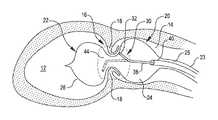
- FIG. 1is a cut away view of an aortic valve of a heart with a treatment balloon placed on both sides of the aortic valve leaflets, according aspects of the present invention
- FIG. 2is a partial perspective view of an electrode pair which may be employed as a shock wave generator within the treatment balloon of FIG. 2 according to aspects of the invention
- FIG. 3is a simplified schematic diagram of a valvuloplasty system according to aspects of the invention.
- FIG. 4is a partial perspective view of another electrode pair which may be employed as a shock wave generator within the treatment balloon of FIG. 2 according to further aspects of the invention
- FIG. 5is a sectional view taken along lines 5 - 5 of FIG. 4 ;
- FIG. 6is a partial perspective view of an electrode pair which may be employed as a shock wave generator within the treatment balloon of FIG. 2 that includes a reflector that reflects and focuses the shock waves in a desired direction according to further aspects of the invention;
- FIG. 7is simplified side view illustrating the operation of the reflector of FIG. 6 ;
- FIG. 8is a cut away view of an aortic valve of a heart with another treatment balloon placed on both sides of the aortic valve leaflets at the distal end of a valvuloplasty system, according to further aspects of the present invention.
- FIG. 9is a plan view of the proximal end of the valvuloplasty system of FIG. 8 .
- FIG. 1it is a cut away view of an aortic valve 16 of a heart with a treatment balloon 22 placed on both sides of the aortic valve leaflets 18 . Also shown are the left ventricle 12 and the aorta 14 of the heart. Valves of the heart, such as the aortic valve 16 can become stenotic and calcified. More particularly, the opening of the valve defined by the leaflets can become stenotic and calcified. This can restrict the size of the opening as the valve leaflets 18 are thickened with calcium deposits and fibrotic tissue. The thickened leaflets 18 and smaller valve opening restrict blood flow from the heart creating excess work for the heart and poor cardiac output. As previously mentioned, current treatment includes replacement of the valve or attempts to stretch the valve annulus with a balloon.
- FIG. 1also shows a valvuloplasty system 20 embodying aspects of the present invention within the aortic valve 16 to treat the stenotic and calcified valve 16 .
- the system 20includes a treatment balloon 22 and a shock wave generator 30 .
- the balloon 22includes two longitudinally spaced chambers 24 and 26 placed on opposed sides of the aortic valve leaflets 18 .
- the balloon 22may be formed from a compliant or a non-compliant material.
- the balloonis at the distal end of a carrier formed by an elongated tube 23 .
- the two longitudinally spaced chambers 24 and 26share a common inflation lumen 25 of the tube 23 to permit the balloon 22 to be filled with a liquid, such as saline. Alternatively the balloon chambers 24 and 26 may not share the same inflation fluid path.
- the shock wave generator 30includes at least one electrode that produces electrical arcs within the balloon to produce shock waves within the confined liquid.
- the shock wavespropagate through the liquid and impinge upon the balloon wall and the valve.
- the impinging shock wavescause the calcified material on the valve to break and/or soften. This permit the valve opening to be widened or the calcified material to be removed.
- the shock wave generator 30includes an electrode pair 32 .
- Such an electrode pair 32is shown in greater detail in FIG. 2 , to which attention is temporarily drawn.
- the electrode pair 32includes a first electrode 34 and a second electrode 36 .
- the electrodesare coaxially disposed with electrode 34 being a center electrode and electrode 36 being an outer electrode circumscribing the center electrode 34 .
- the electrode pair 32are carried by an integral elongated element or extension 38 that may extend back to the proximal end of the system 20 .
- the elongated element 38is thus formed by both extensions of the center electrode 34 and the outer electrode 36 .
- the electrode pair 32is offset from the element 38 at an angle.
- the element 38causes the electrode pair to subscribe a circular area.
- the elementextends down a sheath 40 which in turn may also extend back to the proximal end of the system 20 .
- the element 38 and the sheath 40are axially displaceable within the balloon and with respect to each other as indicated by arrows 42 at the proximal end of the system.
- the electrode pair 32is drawn further into the sheath 40 and deflected to a lesser extent to subscribe a circular area of smaller radius.
- the electrode pair 32is extended further out of the sheath 40 and deflects to a greater extent to subscribe a circular area of larger radius.
- the electrode pair 32may be moved axially within the balloon chambers 24 and 26 .
- the axial movement of the electrode pair 32 together with the rotational movement of the element 38causes the electrode pair 32 to subscribe a cylindrical space represented in dashed lines and designated with reference numeral 44 in FIG. 1 .
- This movement of the electrode pair 32permits the electrode pair 32 to be used to treat the valve 16 in both balloon chambers 24 and 26 and on both sides of the leaflets 18 . It also permits the shock waves produced by the electrode pair to be directed towards specific areas of the valve 16 to enhance treatment and to vary the intensity of the shock wave impingement on the valve 16 .
- FIG. 3is a simplified schematic diagram of the shock wave generator 30 . It includes a high voltage power supply 31 , a series resistance 33 , a capacitance 35 , and a high voltage switch 37 .
- the voltage needed to form the electrical arcwill depend on the gap between the electrodes 34 and 36 and may range between 100 to 3000 volts, for example.
- the high voltage switch 37can be set to control the duration of the pulses applied to the electrodes. The pulse duration will depend on the surface area of the electrodes 34 and 36 and needs to be sufficient to generate a gas bubble at the surface of the electrode causing a plasma arc of electric current to jump the bubble and create a rapidly expanding and collapsing bubble, which creates the shock wave in the balloon.
- shock wavescan be as short as a few microseconds. It may be noted in FIG. 3 , that the negative terminal of the power supply 31 is connected to the center electrode 34 . Also, the shock waves may be synchronized to the R wave of the heart in a manner as described for example in application No. 61/061,170 filed on Jun. 13, 2008, which application is incorporated herein in its entirety. Thus, the high voltage pulses within the shock wave generator 30 are applied to the electrode pairs 34 and 36 in a manner as described in the aforementioned application Ser. No. 61/061,170 to create shockwaves within the fluid within the balloon 22 . The shock waves impinge upon the valve leaflets 18 and the valve annulus to cause the break-up of calcium deposits and fibrotic tissue on the valve leaflets 18 and annulus to open and smooth the aortic valve 16 .
- the electrode pair 52includes a center electrode 54 and an outer electrode 56 .
- the outer electrode 56circumscribes the inner electrode 54 .
- the electrode pair 52further includes a cage 55 that is carried by the outer electrode 56 .
- the cage 55includes a plurality of elements 57 that enclose the inner electrode 54 to protect the inner electrode from contacting the inner surface of the balloon 22 .
- the cage elements 57may be formed of conductive wire 58 covered at least in part with an insulator 59 .
- the cage elementsmay be form entirely of a non-conductor material.
- FIG. 6is a partial perspective view of a further electrode pair which may be employed as a shock wave generator within the treatment balloon of FIG. 1 according to further aspects of the invention.
- the electrode pair 62includes a center electrode 64 and an outer electrode 66 .
- the outer electrode 66takes the form of a reflector 68 .
- the reflector 68provides a narrowed envelope of shock wave energy and directs the shock waves in a desired direction.
- the concentration of the shock wave energy provided by the reflectorfurther contributes towards the provision of shock wave energy sufficient to soften or break the calcified regions of the valve being treated.
- the reflector 68by being a part of the outer electrode 66 , is moveable with the electrode pair 62 .
- the center electrode 64is shown connected to the negative side of the power supply. It has been observed that the bubble causing the shock waves emanate from the negative electrode.
- the reflector 68by enveloping the electrode 64 from which the shock wave bubble emanates provides uniform control and distribution of the shock wave energy within the narrowed envelope of energy. As in the previous embodiment, the reflector may also serve to protect the center electrode 64 from contacting the inner surface of the balloon 22 .
- FIG. 8is a cut away view of another valvuloplasty system 120 embodying the present invention.
- the systemincludes a treatment balloon 122 deployed on both sides of the leaflets 18 of an aortic valve 16 .
- the balloon 122may be formed from a compliant or a non-compliant material.
- the balloonas seen in FIG. 8 , is at the distal end of a carrier formed by an elongated tube 123 .
- the treatment balloon 122has two longitudinally spaced chambers 124 and 126 that share a common inflation lumen 125 of the tube 123 . Alternatively the balloon chambers 124 and 126 may not share the same inflation fluid path.
- the chambers 124 and 126are longitudinally spaced such that chamber 124 is positioned on one side of the aortic valve leaflets 18 and chamber 126 is positioned on the other side of the aortic valve leaflets 18 .
- the chambers 124 and 126may be inflated with saline/contrast mixture, for example.
- the system 120further includes a shockwave generator 130 shown within balloon chamber 124 and a shock wave generator 131 shown within balloon chamber 126 .
- Each of the shock wave generatorsincludes an electrode pair.
- shock wave generator 130includes electrode pair 132 and shock wave generator 131 includes electrode pair 133 .
- the electrode pairs 132 and 133may take the form of any one of the electrode pairs previously described.
- the shock wave pairs 132 and 133are carried by respective integral elongated elements 134 and 135 . It is of course not required that the elongated elements be integral with their respective electrode pairs.
- the elongated elements 134 and 135extend through sheaths 138 and 139 respectively to the proximal end of the system 120 .
- the elongated elements 134 and 135are each rotatable as indicated enable their respective electrode pairs 132 and 133 to subscribe a circular area as indicate by arrows 136 and 137 .
- the sheaths 138 and 139are axially within the carrier 123 and balloon 122 as indicated by arrows 140 and 141 .
- the elongated elements 134 and 135are axially moveable within their respective sheaths 138 and 139 .
- the electrode pairs 132 and 133are afforded three dimensional freedom of movement to subscribe cylindrical space.
- the shock wave generators 130 and 131may be active to generate shock waves either together are individually. If it becomes necessary to rotate the proximal electrode pair 132 , the electrode pair 133 may first be moved proximally by axial movement of its sheath 139 so that it is proximal to electrode pair 132 and out of the way. As may be further noted in FIG. 8 , the distal electrode pair 133 is reflexed in the proximal direction pointing towards the distal side of the leaflets 18 . This provides more direct access to the aortic valve 16 by the electrode pair 133 . To this end, shockwave generator 131 has a preformed shape defining a 180 degree bend. It assumes this shape to reflex electrode pair 133 when it extends out of sheath 139 .
- the valvuloplasty system 120 of FIG. 8provides the physician with many degrees of freedom for accessing the aortic valve with the shock wave generators 130 and 131 .
- the movement of the shock wave generators 130 and 131 enabled by this embodimentpermits the physician to adjust the distance of the shock wave generators from the valve 16 and the approach angle to the valve 16 in order to maximize the available shock wave energy. It also enables the gentle softening and breaking of the calcified regions of an anatomical feature that is difficult reach and fully access.
- FIG. 9it is a plan view of the proximal end of the valvuloplasty system 120 of FIG. 8 .
- the yoke assembly 150is connected to the carrier 123 and includes a fill port 152 to permit the inflation fluid, such as saline, into the inflation lumen 125 ( FIG. 8 ) of the carrier 123 .
- the yokehas extensions 154 and 156 associated with the shock wave generators 130 and 131 respectively.
- Each extensionaccommodates controls for axially displacing the sheaths and for axially displacing and rotating the elongated elements that extend through the sheaths and carry the electrode pairs of the shock wave generators.
- the proximal end of the system 120has a control knob 158 for controlling the axial displacement of sheath 138 of shock wave generator 130 and a control knob 160 for controlling the axial displacement and rotation of the elongated element 134 of shockwave generator 130 .
- An electrical connector 162provides electrical connections to the electrode pair 132 of shock wave generator 130 .
- the proximal end of the system 120has another control knob 178 for controlling the axial displacement of sheath 139 of shock wave generator 131 and a control knob 180 for controlling the axial displacement and rotation of the elongated element 135 of shockwave generator 131 .
- An electrical connector 182provides electrical connections to the electrode pair 133 of shock wave generator 131 .
- the extensionfurther includes a guide wire port 184 for receiving a guide wire.
- the guide wireserves to feed the system into place in a manner known in the art.
- the guide wirehas not been shown to avoid undue complication.
Landscapes
- Health & Medical Sciences (AREA)
- Surgery (AREA)
- Engineering & Computer Science (AREA)
- Life Sciences & Earth Sciences (AREA)
- Biomedical Technology (AREA)
- Nuclear Medicine, Radiotherapy & Molecular Imaging (AREA)
- Vascular Medicine (AREA)
- Orthopedic Medicine & Surgery (AREA)
- Mechanical Engineering (AREA)
- Heart & Thoracic Surgery (AREA)
- Medical Informatics (AREA)
- Molecular Biology (AREA)
- Animal Behavior & Ethology (AREA)
- General Health & Medical Sciences (AREA)
- Public Health (AREA)
- Veterinary Medicine (AREA)
- Surgical Instruments (AREA)
Abstract
Description
Claims (4)
Priority Applications (1)
| Application Number | Priority Date | Filing Date | Title |
|---|---|---|---|
| US15/729,238US10478202B2 (en) | 2011-11-08 | 2017-10-10 | Shock wave valvuloplasty device with moveable shock wave generator |
Applications Claiming Priority (5)
| Application Number | Priority Date | Filing Date | Title |
|---|---|---|---|
| US13/291,875US8574247B2 (en) | 2011-11-08 | 2011-11-08 | Shock wave valvuloplasty device with moveable shock wave generator |
| US14/046,635US8709075B2 (en) | 2011-11-08 | 2013-10-04 | Shock wave valvuloplasty device with moveable shock wave generator |
| US14/229,735US9289224B2 (en) | 2011-11-08 | 2014-03-28 | Shock wave valvuloplasty device with moveable shock wave generator |
| US15/018,160US9814476B2 (en) | 2011-11-08 | 2016-02-08 | Shock wave valvuloplasty device with moveable shock wave generator |
| US15/729,238US10478202B2 (en) | 2011-11-08 | 2017-10-10 | Shock wave valvuloplasty device with moveable shock wave generator |
Related Parent Applications (1)
| Application Number | Title | Priority Date | Filing Date |
|---|---|---|---|
| US15/018,160ContinuationUS9814476B2 (en) | 2011-11-08 | 2016-02-08 | Shock wave valvuloplasty device with moveable shock wave generator |
Publications (2)
| Publication Number | Publication Date |
|---|---|
| US20180028208A1 US20180028208A1 (en) | 2018-02-01 |
| US10478202B2true US10478202B2 (en) | 2019-11-19 |
Family
ID=48224210
Family Applications (5)
| Application Number | Title | Priority Date | Filing Date |
|---|---|---|---|
| US13/291,875ActiveUS8574247B2 (en) | 2011-11-08 | 2011-11-08 | Shock wave valvuloplasty device with moveable shock wave generator |
| US14/046,635ActiveUS8709075B2 (en) | 2011-11-08 | 2013-10-04 | Shock wave valvuloplasty device with moveable shock wave generator |
| US14/229,735ActiveUS9289224B2 (en) | 2011-11-08 | 2014-03-28 | Shock wave valvuloplasty device with moveable shock wave generator |
| US15/018,160ActiveUS9814476B2 (en) | 2011-11-08 | 2016-02-08 | Shock wave valvuloplasty device with moveable shock wave generator |
| US15/729,238Active2032-06-22US10478202B2 (en) | 2011-11-08 | 2017-10-10 | Shock wave valvuloplasty device with moveable shock wave generator |
Family Applications Before (4)
| Application Number | Title | Priority Date | Filing Date |
|---|---|---|---|
| US13/291,875ActiveUS8574247B2 (en) | 2011-11-08 | 2011-11-08 | Shock wave valvuloplasty device with moveable shock wave generator |
| US14/046,635ActiveUS8709075B2 (en) | 2011-11-08 | 2013-10-04 | Shock wave valvuloplasty device with moveable shock wave generator |
| US14/229,735ActiveUS9289224B2 (en) | 2011-11-08 | 2014-03-28 | Shock wave valvuloplasty device with moveable shock wave generator |
| US15/018,160ActiveUS9814476B2 (en) | 2011-11-08 | 2016-02-08 | Shock wave valvuloplasty device with moveable shock wave generator |
Country Status (2)
| Country | Link |
|---|---|
| US (5) | US8574247B2 (en) |
| WO (1) | WO2013070750A1 (en) |
Cited By (20)
| Publication number | Priority date | Publication date | Assignee | Title |
|---|---|---|---|---|
| US11517713B2 (en) | 2019-06-26 | 2022-12-06 | Boston Scientific Scimed, Inc. | Light guide protection structures for plasma system to disrupt vascular lesions |
| US11583339B2 (en) | 2019-10-31 | 2023-02-21 | Bolt Medical, Inc. | Asymmetrical balloon for intravascular lithotripsy device and method |
| US11648057B2 (en) | 2021-05-10 | 2023-05-16 | Bolt Medical, Inc. | Optical analyzer assembly with safety shutdown system for intravascular lithotripsy device |
| US11660427B2 (en) | 2019-06-24 | 2023-05-30 | Boston Scientific Scimed, Inc. | Superheating system for inertial impulse generation to disrupt vascular lesions |
| US11672599B2 (en) | 2020-03-09 | 2023-06-13 | Bolt Medical, Inc. | Acoustic performance monitoring system and method within intravascular lithotripsy device |
| US11672585B2 (en) | 2021-01-12 | 2023-06-13 | Bolt Medical, Inc. | Balloon assembly for valvuloplasty catheter system |
| US11707323B2 (en) | 2020-04-03 | 2023-07-25 | Bolt Medical, Inc. | Electrical analyzer assembly for intravascular lithotripsy device |
| US11717139B2 (en) | 2019-06-19 | 2023-08-08 | Bolt Medical, Inc. | Plasma creation via nonaqueous optical breakdown of laser pulse energy for breakup of vascular calcium |
| US11806075B2 (en) | 2021-06-07 | 2023-11-07 | Bolt Medical, Inc. | Active alignment system and method for laser optical coupling |
| US11819229B2 (en) | 2019-06-19 | 2023-11-21 | Boston Scientific Scimed, Inc. | Balloon surface photoacoustic pressure wave generation to disrupt vascular lesions |
| US11839391B2 (en) | 2021-12-14 | 2023-12-12 | Bolt Medical, Inc. | Optical emitter housing assembly for intravascular lithotripsy device |
| US11903642B2 (en) | 2020-03-18 | 2024-02-20 | Bolt Medical, Inc. | Optical analyzer assembly and method for intravascular lithotripsy device |
| US12011184B2 (en) | 2020-02-10 | 2024-06-18 | Elixir Medical Corporation | Methods and apparatus for plaque disruption |
| US12016610B2 (en) | 2020-12-11 | 2024-06-25 | Bolt Medical, Inc. | Catheter system for valvuloplasty procedure |
| US12102384B2 (en) | 2019-11-13 | 2024-10-01 | Bolt Medical, Inc. | Dynamic intravascular lithotripsy device with movable energy guide |
| US12207870B2 (en) | 2020-06-15 | 2025-01-28 | Boston Scientific Scimed, Inc. | Spectroscopic tissue identification for balloon intravascular lithotripsy guidance |
| US12274497B2 (en) | 2019-12-18 | 2025-04-15 | Bolt Medical, Inc. | Multiplexer for laser-driven intravascular lithotripsy device |
| US12274485B2 (en) | 2021-01-12 | 2025-04-15 | Bolt Medical, Inc. | Balloon assembly for valvuloplasty catheter system |
| US12295654B2 (en) | 2020-06-03 | 2025-05-13 | Boston Scientific Scimed, Inc. | System and method for maintaining balloon integrity within intravascular lithotripsy device with plasma generator |
| US12402946B2 (en) | 2019-06-19 | 2025-09-02 | Boston Scientific Scimed, Inc. | Breakdown of laser pulse energy for breakup of vascular calcium |
Families Citing this family (81)
| Publication number | Priority date | Publication date | Assignee | Title |
|---|---|---|---|---|
| US20100036294A1 (en) | 2008-05-07 | 2010-02-11 | Robert Mantell | Radially-Firing Electrohydraulic Lithotripsy Probe |
| US10702293B2 (en) | 2008-06-13 | 2020-07-07 | Shockwave Medical, Inc. | Two-stage method for treating calcified lesions within the wall of a blood vessel |
| WO2009152352A2 (en) | 2008-06-13 | 2009-12-17 | Aspen Medtech, Inc. | Shockwave balloon catheter system |
| US9072534B2 (en) | 2008-06-13 | 2015-07-07 | Shockwave Medical, Inc. | Non-cavitation shockwave balloon catheter system |
| US9044618B2 (en) | 2008-11-05 | 2015-06-02 | Shockwave Medical, Inc. | Shockwave valvuloplasty catheter system |
| US8574247B2 (en) | 2011-11-08 | 2013-11-05 | Shockwave Medical, Inc. | Shock wave valvuloplasty device with moveable shock wave generator |
| US9504604B2 (en)* | 2011-12-16 | 2016-11-29 | Auris Surgical Robotics, Inc. | Lithotripsy eye treatment |
| US9642673B2 (en) | 2012-06-27 | 2017-05-09 | Shockwave Medical, Inc. | Shock wave balloon catheter with multiple shock wave sources |
| CA2881184C (en)* | 2012-08-06 | 2019-06-04 | Shockwave Medical, Inc. | Shockwave catheter |
| AU2013300176B2 (en) | 2012-08-06 | 2017-08-17 | Shockwave Medical, Inc. | Low profile electrodes for an angioplasty shock wave catheter |
| US9554815B2 (en) | 2012-08-08 | 2017-01-31 | Shockwave Medical, Inc. | Shockwave valvuloplasty with multiple balloons |
| US9333000B2 (en) | 2012-09-13 | 2016-05-10 | Shockwave Medical, Inc. | Shockwave catheter system with energy control |
| US9522012B2 (en) | 2012-09-13 | 2016-12-20 | Shockwave Medical, Inc. | Shockwave catheter system with energy control |
| CA3075128C (en) | 2013-03-11 | 2022-07-19 | Northgate Technologies Inc. | Unfocused electrohydraulic lithotripter |
| US10201387B2 (en) | 2013-03-13 | 2019-02-12 | The Spectranetics Corporation | Laser-induced fluid filled balloon catheter |
| US9320530B2 (en) | 2013-03-13 | 2016-04-26 | The Spectranetics Corporation | Assisted cutting balloon |
| US10842567B2 (en) | 2013-03-13 | 2020-11-24 | The Spectranetics Corporation | Laser-induced fluid filled balloon catheter |
| WO2014201165A1 (en) | 2013-06-11 | 2014-12-18 | Auris Surgical Robotics, Inc. | System for robotic assisted cataract surgery |
| US10426661B2 (en) | 2013-08-13 | 2019-10-01 | Auris Health, Inc. | Method and apparatus for laser assisted cataract surgery |
| US10220192B2 (en)* | 2014-04-23 | 2019-03-05 | Intervalve Medical, Inc. | Post dilation balloon with marker bands for use with stented valves |
| US11246659B2 (en) | 2014-08-25 | 2022-02-15 | The Spectranetics Corporation | Liquid laser-induced pressure wave emitting catheter sheath |
| US20160135828A1 (en) | 2014-11-14 | 2016-05-19 | Shockwave Medical, Inc. | Shock wave valvuloplasty device and methods |
| EP3240603B1 (en) | 2014-12-30 | 2019-05-01 | The Spectranetics Corporation | Laser-induced fluid filled balloon catheter |
| US11058492B2 (en) | 2014-12-30 | 2021-07-13 | The Spectranetics Corporation | Laser-induced pressure wave emitting catheter sheath |
| WO2016109739A1 (en)* | 2014-12-30 | 2016-07-07 | The Spectranetics Corporation | Electrically-induced pressure wave emitting catheter sheath |
| US10327846B1 (en) | 2015-08-25 | 2019-06-25 | The Spectranetics Corporation | Methods for treating vascular stenoses including laser atherectomy and drug delivery via drug-coated balloons |
| WO2017087195A1 (en) | 2015-11-18 | 2017-05-26 | Shockwave Medical, Inc. | Shock wave electrodes |
| US10226265B2 (en) | 2016-04-25 | 2019-03-12 | Shockwave Medical, Inc. | Shock wave device with polarity switching |
| EP3484421A1 (en) | 2016-07-13 | 2019-05-22 | Boston Scientific Scimed Inc. | Apparatus and method for maintaining patency in a vessel adjacent to nearby surgery |
| AU2017339980B2 (en) | 2016-10-06 | 2022-08-18 | Shockwave Medical, Inc. | Aortic leaflet repair using shock wave applicators |
| US10357264B2 (en)* | 2016-12-06 | 2019-07-23 | Shockwave Medical, Inc. | Shock wave balloon catheter with insertable electrodes |
| WO2018194980A1 (en) | 2017-04-21 | 2018-10-25 | Boston Scientific Scimed, Inc. | Lithotripsy angioplasty devices and methods |
| US10561428B2 (en) | 2017-04-21 | 2020-02-18 | Boston Scientific Scimed, Inc. | Lithotripsy angioplasty devices and methods |
| US11020135B1 (en) | 2017-04-25 | 2021-06-01 | Shockwave Medical, Inc. | Shock wave device for treating vascular plaques |
| US10966737B2 (en) | 2017-06-19 | 2021-04-06 | Shockwave Medical, Inc. | Device and method for generating forward directed shock waves |
| NL2019807B1 (en) | 2017-10-26 | 2019-05-06 | Boston Scient Scimed Inc | Shockwave generating device |
| US11071557B2 (en)* | 2017-10-19 | 2021-07-27 | Medtronic Vascular, Inc. | Catheter for creating pulse wave within vasculature |
| US10709462B2 (en) | 2017-11-17 | 2020-07-14 | Shockwave Medical, Inc. | Low profile electrodes for a shock wave catheter |
| US11596438B2 (en) | 2018-01-16 | 2023-03-07 | Daniel Ezra Walzman | Bypass catheter |
| US10799674B2 (en) | 2018-01-16 | 2020-10-13 | Daniel Ezra Walzman | Bypass catheter |
| US11006996B2 (en)* | 2018-01-16 | 2021-05-18 | Daniel Ezra Walzman | Torus balloon with energy emitters for intravascular lithotripsy |
| US11596769B2 (en) | 2018-01-16 | 2023-03-07 | Daniel Ezra Walzman | Bypass catheter |
| US11103262B2 (en) | 2018-03-14 | 2021-08-31 | Boston Scientific Scimed, Inc. | Balloon-based intravascular ultrasound system for treatment of vascular lesions |
| EP3809988B1 (en) | 2018-06-21 | 2023-06-07 | Shockwave Medical, Inc. | System for treating occlusions in body lumens |
| CN109223100A (en)* | 2018-09-03 | 2019-01-18 | 沛嘉医疗科技(苏州)有限公司 | It is a kind of for treating the device and its application method of heart valve and angiosteosis |
| WO2020086361A1 (en) | 2018-10-24 | 2020-04-30 | Boston Scientific Scimed, Inc. | Photoacoustic pressure wave generation for intravascular calcification disruption |
| US11266425B2 (en) | 2018-10-25 | 2022-03-08 | Medtronic Vascular, Inc. | Cavitation catheter |
| US11357958B2 (en) | 2018-10-25 | 2022-06-14 | Medtronic Vascular, Inc. | Devices and techniques for cardiovascular intervention |
| US11826092B2 (en) | 2018-10-25 | 2023-11-28 | Medtronic Vascular, Inc. | Cavitation guidewire |
| US11266817B2 (en) | 2018-10-25 | 2022-03-08 | Medtronic Vascular, Inc. | Cavitation catheter |
| US11464658B2 (en) | 2018-10-25 | 2022-10-11 | Medtronic Vascular, Inc. | Implantable medical device with cavitation features |
| US11399862B2 (en) | 2019-06-24 | 2022-08-02 | Boston Scientific Scimed, Inc. | Propulsion system for inertial energy transfer to disrupt vascular lesions |
| EP4512350A3 (en) | 2019-09-24 | 2025-05-07 | Shockwave Medical, Inc. | Low profile electrodes for a shock wave catheter |
| WO2021061451A1 (en) | 2019-09-24 | 2021-04-01 | Shockwave Medical, Inc. | Lesion crossing shock wave catheter |
| WO2021061523A1 (en) | 2019-09-24 | 2021-04-01 | Shockwave Medical, Inc. | System for treating thrombus in body lumens |
| WO2021081105A1 (en) | 2019-10-21 | 2021-04-29 | University Of Virginia Patent Foundation | Methods, systems, and computer readable media for utilizing a therapeutic ultrasound device to perform mitral valve decalcification |
| US11992232B2 (en) | 2020-10-27 | 2024-05-28 | Shockwave Medical, Inc. | System for treating thrombus in body lumens |
| US12232755B2 (en) | 2020-12-11 | 2025-02-25 | Shockwave Medical, Inc. | Lesion crossing shock wave catheter |
| WO2022187058A1 (en)* | 2021-03-01 | 2022-09-09 | Bolt Medical, Inc. | Valvuloplasty treatment assembly and method using directed bubble energy |
| CN115363689A (en)* | 2021-05-21 | 2022-11-22 | 上海微创心通医疗科技有限公司 | Medical catheter and medical device |
| CN113332570B (en)* | 2021-07-02 | 2025-04-22 | 苏州中荟医疗科技有限公司 | A balloon catheter and shock wave generating system |
| US11957369B2 (en) | 2021-08-05 | 2024-04-16 | Nextern Innovation, Llc | Intravascular lithotripsy systems and methods |
| US11877761B2 (en) | 2021-08-05 | 2024-01-23 | Nextern Innovation, Llc | Systems, devices and methods for monitoring voltage and current and controlling voltage of voltage pulse generators |
| US11801066B2 (en) | 2021-08-05 | 2023-10-31 | Nextern Innovation, Llc | Systems, devices and methods for selection of arc location within a lithoplasty balloon spark gap |
| US12089861B2 (en) | 2021-08-05 | 2024-09-17 | Nextern Innovation, Llc | Intravascular lithotripsy system and device |
| US11896248B2 (en) | 2021-08-05 | 2024-02-13 | Nextern Innovation, Llc | Systems, devices and methods for generating subsonic pressure waves in intravascular lithotripsy |
| US12023098B2 (en) | 2021-10-05 | 2024-07-02 | Shockwave Medical, Inc. | Lesion crossing shock wave catheter |
| CN116035651A (en)* | 2022-11-08 | 2023-05-02 | 杭州莱恩瑟特医疗技术有限公司 | Electrode leads for electrohydraulic lithotripsy |
| CN116058918A (en)* | 2023-02-10 | 2023-05-05 | 深圳市赛禾医疗技术有限公司 | Valve Shockwave Balloon Catheter |
| US12290268B2 (en) | 2023-03-31 | 2025-05-06 | Shockwave Medical, Inc. | Shockwave catheters for treating rhinosinusitis |
| US12035932B1 (en) | 2023-04-21 | 2024-07-16 | Shockwave Medical, Inc. | Intravascular lithotripsy catheter with slotted emitter bands |
| US12220141B2 (en) | 2023-06-29 | 2025-02-11 | Shockwave Medical, Inc. | Catheter system with independently controllable bubble and arc generation |
| CN117159094B (en)* | 2023-11-02 | 2024-01-12 | 苏州中荟医疗科技有限公司 | Shock wave treatment catheter and equipment thereof |
| US12426904B2 (en) | 2023-11-17 | 2025-09-30 | Shockwave Medical, Inc. | Intravascular lithotripsy catheter with oscillating impactor |
| US12402899B2 (en) | 2023-11-30 | 2025-09-02 | Shockwave Medical, Inc. | Systems, devices, and methods for generating shock waves in a forward direction |
| WO2025171173A1 (en) | 2024-02-08 | 2025-08-14 | IV-X Medical, LLC | Intravascular lithotripsy system |
| US12433620B2 (en) | 2024-02-23 | 2025-10-07 | Shockwave Medical, Inc. | Locus emitter shock wave catheter devices with increased longevity and higher sonic output |
| US20250281191A1 (en)* | 2024-03-05 | 2025-09-11 | Shockwave Medical, Inc. | Shock wave catheter with retractable enclosure |
| CN117942131B (en)* | 2024-03-27 | 2024-05-31 | 苏州中荟医疗科技有限公司 | Impact waveguide tube and system |
| US12178458B1 (en) | 2024-05-16 | 2024-12-31 | Shockwave Medical, Inc. | Guidewireless shock wave catheters |
| CN118662191B (en)* | 2024-08-22 | 2025-01-03 | 苏州中荟医疗科技有限公司 | A shock wave guide system |
Citations (142)
| Publication number | Priority date | Publication date | Assignee | Title |
|---|---|---|---|---|
| US3413976A (en)* | 1963-07-29 | 1968-12-03 | G Elektrotekhnichesky Zd Vef | Arrangement for removal of concretions from urinary tract |
| US3785382A (en) | 1971-05-14 | 1974-01-15 | Wolf Gmbh Richard | Device for destroying stones in the bladder, in the ureter, in the kidneys and the like |
| US3902499A (en) | 1974-01-02 | 1975-09-02 | Hoffman Saul | Stone disintegrator |
| US4027674A (en) | 1975-06-06 | 1977-06-07 | Tessler Arthur N | Method and device for removing concretions within human ducts |
| US4030505A (en) | 1975-11-28 | 1977-06-21 | Calculus Instruments Ltd. | Method and device for disintegrating stones in human ducts |
| DE3038445A1 (en) | 1980-10-11 | 1982-05-27 | Dornier Gmbh, 7990 Friedrichshafen | Pressure wave generator for diagnosis and therapy - has spark gap in inflatable balloon at end of catheter |
| JPS60191353U (en) | 1984-05-25 | 1985-12-18 | 日立工機株式会社 | Ink ribbon feeding control device |
| US4662126A (en) | 1986-05-23 | 1987-05-05 | Fike Corporation | Vibration resistant explosion control vent |
| US4671254A (en) | 1985-03-01 | 1987-06-09 | Memorial Hospital For Cancer And Allied Diseases | Non-surgical method for suppression of tumor growth |
| JPS6299210U (en) | 1985-12-12 | 1987-06-24 | ||
| US4685458A (en) | 1984-03-01 | 1987-08-11 | Vaser, Inc. | Angioplasty catheter and method for use thereof |
| JPS62275446A (en) | 1986-05-21 | 1987-11-30 | オリンパス光学工業株式会社 | Discharge stone crushing apparatus |
| US4809682A (en) | 1985-12-12 | 1989-03-07 | Dornier Medizintechnik Gmbh | Underwater electrodes for contactless lithotripsy |
| US4878495A (en) | 1987-05-15 | 1989-11-07 | Joseph Grayzel | Valvuloplasty device with satellite expansion means |
| WO1989011307A1 (en) | 1988-05-26 | 1989-11-30 | The Regents Of The University Of California | Perfusion balloon catheter |
| JPH0363059A (en) | 1989-04-26 | 1991-03-19 | Advanced Cardiovascular Syst Inc | Blood flow measurement using self-irrigation catheter for blood vessel formation and its device |
| US5009232A (en) | 1988-08-17 | 1991-04-23 | Siemens Aktiengesellschaft | Extracorporeal lithotripsy apparatus using high intensity shock waves for calculus disintegration and low intensity shock waves for imaging |
| EP0442199A2 (en) | 1990-02-12 | 1991-08-21 | BS & B SAFETY SYSTEMS, INC. | Low pressure non-fragmenting rupture disks |
| US5061240A (en) | 1990-04-02 | 1991-10-29 | George Cherian | Balloon tip catheter for venous valve ablation |
| US5078717A (en) | 1989-04-13 | 1992-01-07 | Everest Medical Corporation | Ablation catheter with selectively deployable electrodes |
| US5103804A (en) | 1990-07-03 | 1992-04-14 | Boston Scientific Corporation | Expandable tip hemostatic probes and the like |
| US5152768A (en) | 1991-02-26 | 1992-10-06 | Bhatta Krishna M | Electrohydraulic lithotripsy |
| US5152767A (en) | 1990-11-23 | 1992-10-06 | Northgate Technologies, Inc. | Invasive lithotripter with focused shockwave |
| US5154722A (en) | 1988-05-05 | 1992-10-13 | Circon Corporation | Electrohydraulic probe having a controlled discharge path |
| US5176675A (en) | 1985-04-24 | 1993-01-05 | The General Hospital Corporation | Use of lasers to break down objects for removal from within the body |
| US5195508A (en) | 1990-05-18 | 1993-03-23 | Dornier Medizintechnik Gmbh | Spark gap unit for lithotripsy |
| US5246447A (en) | 1989-02-22 | 1993-09-21 | Physical Sciences, Inc. | Impact lithotripsy |
| EP0571306A1 (en) | 1992-05-22 | 1993-11-24 | LASER MEDICAL TECHNOLOGY, Inc. | Apparatus and method for removal of deposits from the walls of body passages |
| US5281231A (en) | 1989-02-22 | 1994-01-25 | Physical Sciences, Inc. | Impact lithotrypsy |
| US5295958A (en) | 1991-04-04 | 1994-03-22 | Shturman Cardiology Systems, Inc. | Method and apparatus for in vivo heart valve decalcification |
| JPH06125915A (en) | 1992-10-21 | 1994-05-10 | Inter Noba Kk | Catheter type medical instrument |
| US5324255A (en) | 1991-01-11 | 1994-06-28 | Baxter International Inc. | Angioplasty and ablative devices having onboard ultrasound components and devices and methods for utilizing ultrasound to treat or prevent vasopasm |
| US5336234A (en) | 1992-04-17 | 1994-08-09 | Interventional Technologies, Inc. | Method and apparatus for dilatation of a stenotic vessel |
| US5368591A (en) | 1988-10-28 | 1994-11-29 | Prutech Research And Development Partnership Ii | Heated balloon catheters |
| JPH0747135A (en) | 1993-02-05 | 1995-02-21 | Joe W & Dorothy Dorsett Brown Found:The | Ultrasonic angioplasty balloon catheter |
| US5395335A (en) | 1991-05-24 | 1995-03-07 | Jang; G. David | Universal mode vascular catheter system |
| US5417208A (en) | 1993-10-12 | 1995-05-23 | Arrow International Investment Corp. | Electrode-carrying catheter and method of making same |
| US5425735A (en) | 1989-02-22 | 1995-06-20 | Psi Medical Products, Inc. | Shielded tip catheter for lithotripsy |
| US5472406A (en) | 1991-10-03 | 1995-12-05 | The General Hospital Corporation | Apparatus and method for vasodilation |
| US5505702A (en) | 1992-04-09 | 1996-04-09 | Scimed Life Systems, Inc. | Balloon catheter for dilatation and perfusion |
| WO1996024297A1 (en) | 1995-02-09 | 1996-08-15 | C.R. Bard, Inc. | Angioplasty catheter used to expand and/or open up blood vessels |
| US5582578A (en) | 1995-08-01 | 1996-12-10 | Duke University | Method for the comminution of concretions |
| US5603731A (en) | 1994-11-21 | 1997-02-18 | Whitney; Douglass G. | Method and apparatus for thwarting thrombosis |
| JPH1099444A (en) | 1996-09-27 | 1998-04-21 | Advanced Cardeovascular Syst Inc | Vibratory stent to open calcified lesion part |
| JPH10314177A (en) | 1997-04-26 | 1998-12-02 | Convergenza Ag | Device with treating catheter |
| US5846218A (en) | 1996-09-05 | 1998-12-08 | Pharmasonics, Inc. | Balloon catheters having ultrasonically driven interface surfaces and methods for their use |
| WO1999002096A1 (en) | 1997-07-08 | 1999-01-21 | The Regents Of The University Of California | Circumferential ablation device assembly and method |
| US6080119A (en) | 1997-05-02 | 2000-06-27 | Hmt Holding Ag | Process and device for generating shock waves for medical uses |
| US6113560A (en) | 1994-09-21 | 2000-09-05 | Hmt High Medical Techologies | Method and device for generating shock waves for medical therapy, particularly for electro-hydraulic lithotripsy |
| US6186963B1 (en) | 1997-05-02 | 2001-02-13 | Hmt Holding Ag | Device for generating acoustic shock waves, especially for medical applications |
| US6210408B1 (en) | 1999-02-24 | 2001-04-03 | Scimed Life Systems, Inc. | Guide wire system for RF recanalization of vascular blockages |
| US6217531B1 (en) | 1997-10-24 | 2001-04-17 | Its Medical Technologies & Services Gmbh | Adjustable electrode and related method |
| US6267747B1 (en) | 1998-05-11 | 2001-07-31 | Cardeon Corporation | Aortic catheter with porous aortic root balloon and methods for inducing cardioplegic arrest |
| US6277138B1 (en) | 1999-08-17 | 2001-08-21 | Scion Cardio-Vascular, Inc. | Filter for embolic material mounted on expandable frame |
| US20010044596A1 (en) | 2000-05-10 | 2001-11-22 | Ali Jaafar | Apparatus and method for treatment of vascular restenosis by electroporation |
| US6352535B1 (en) | 1997-09-25 | 2002-03-05 | Nanoptics, Inc. | Method and a device for electro microsurgery in a physiological liquid environment |
| US6367203B1 (en) | 2000-09-11 | 2002-04-09 | Oklahoma Safety Equipment Co., Inc. | Rupture panel |
| US6371971B1 (en) | 1999-11-15 | 2002-04-16 | Scimed Life Systems, Inc. | Guidewire filter and methods of use |
| US6398792B1 (en) | 1999-06-21 | 2002-06-04 | O'connor Lawrence | Angioplasty catheter with transducer using balloon for focusing of ultrasonic energy and method for use |
| US6406486B1 (en) | 1991-10-03 | 2002-06-18 | The General Hospital Corporation | Apparatus and method for vasodilation |
| US6440061B1 (en) | 2000-03-24 | 2002-08-27 | Donald E. Wenner | Laparoscopic instrument system for real-time biliary exploration and stone removal |
| JP2002538932A (en) | 1999-03-19 | 2002-11-19 | アトリオニクス・インコーポレーテツド | Perimeter linear reformer assembly for providing a modifying perimeter linear band along an inflatable member and method of use and manufacture thereof |
| US6514203B2 (en) | 2001-02-12 | 2003-02-04 | Sonata Technologies Ltd. | Method for ultrasonic coronary thrombolysis |
| US6524251B2 (en) | 1999-10-05 | 2003-02-25 | Omnisonics Medical Technologies, Inc. | Ultrasonic device for tissue ablation and sheath for use therewith |
| US6589253B1 (en) | 1999-12-30 | 2003-07-08 | Advanced Cardiovascular Systems, Inc. | Ultrasonic angioplasty transmission wire |
| US6607003B1 (en) | 2001-04-23 | 2003-08-19 | Oklahoma Safety Equipment Co, | Gasket-lined rupture panel |
| US20030163081A1 (en) | 2002-02-28 | 2003-08-28 | Constantz Brent R. | Localized fluid delivery devices having a porous applicator and methods for using the same |
| US6638246B1 (en) | 2000-11-28 | 2003-10-28 | Scimed Life Systems, Inc. | Medical device for delivery of a biologically active material to a lumen |
| US6652547B2 (en) | 1999-10-05 | 2003-11-25 | Omnisonics Medical Technologies, Inc. | Apparatus and method of removing occlusions using ultrasonic medical device operating in a transverse mode |
| US20030229370A1 (en) | 2002-06-11 | 2003-12-11 | Miller Paul James | Catheter balloon with ultrasonic microscalpel blades |
| JP2004081374A (en) | 2002-08-26 | 2004-03-18 | Dairin Kk | Instrument for removing sediment in tubular organ |
| US20040082859A1 (en) | 2002-07-01 | 2004-04-29 | Alan Schaer | Method and apparatus employing ultrasound energy to treat body sphincters |
| US6736784B1 (en) | 1999-06-24 | 2004-05-18 | Ferton Holding S.A. | Medical instrument for treating biological tissue and method for transmitting pressure waves |
| US20040097996A1 (en) | 1999-10-05 | 2004-05-20 | Omnisonics Medical Technologies, Inc. | Apparatus and method of removing occlusions using an ultrasonic medical device operating in a transverse mode |
| US6740081B2 (en) | 2002-01-25 | 2004-05-25 | Applied Medical Resources Corporation | Electrosurgery with improved control apparatus and method |
| US6755821B1 (en) | 1998-12-08 | 2004-06-29 | Cardiocavitational Systems, Inc. | System and method for stimulation and/or enhancement of myocardial angiogenesis |
| WO2004069072A2 (en) | 2003-02-03 | 2004-08-19 | Cardiofocus, Inc. | Coaxial catheter instruments for ablation with radiant energy |
| US20040249401A1 (en) | 1999-10-05 | 2004-12-09 | Omnisonics Medical Technologies, Inc. | Apparatus and method for an ultrasonic medical device with a non-compliant balloon |
| US20040254570A1 (en) | 2003-06-13 | 2004-12-16 | Andreas Hadjicostis | Endoscopic medical treatment involving acoustic ablation |
| JP2004357792A (en) | 2003-06-02 | 2004-12-24 | Keio Gijuku | Apparatus for preventing and treating vascular restenosis by sound pressure wave induced by high intensity pulsed light irradiation |
| US20050021013A1 (en) | 1997-10-21 | 2005-01-27 | Endo Vasix, Inc. | Photoacoustic removal of occlusions from blood vessels |
| US20050015953A1 (en) | 2003-07-21 | 2005-01-27 | Yaron Keidar | Method for making a spiral array ultrasound transducer |
| US20050059965A1 (en) | 2003-09-15 | 2005-03-17 | Scimed Life Systems, Inc. | Catheter balloons |
| JP2005095410A (en) | 2003-09-25 | 2005-04-14 | Keisei Ika Kogyo Kk | Catheter for thrombus removal |
| US20050090846A1 (en) | 2003-07-18 | 2005-04-28 | Wesley Pedersen | Valvuloplasty devices and methods |
| US20050113822A1 (en) | 2002-07-23 | 2005-05-26 | Fuimaono Kristine B. | Ablation catheter having stabilizing array |
| US20050171527A1 (en) | 2003-12-31 | 2005-08-04 | Sumita Bhola | Circumferential ablation device assembly with an expandable member |
| US20050228372A1 (en) | 2000-08-01 | 2005-10-13 | Sciogen, Inc. | Voltage threshold ablation apparatus |
| WO2005099594A1 (en) | 2004-04-08 | 2005-10-27 | Boston Scientific Limited | Cutting balloon catheter and method for blade mounting |
| US20050245866A1 (en) | 1996-05-20 | 2005-11-03 | Medtronic Vascular, Inc. | Exchange method for emboli containment |
| US20050251131A1 (en) | 1997-05-09 | 2005-11-10 | Lesh Michael D | Circumferential ablation device assembly |
| US20060004286A1 (en) | 2004-04-21 | 2006-01-05 | Acclarent, Inc. | Methods and devices for performing procedures within the ear, nose, throat and paranasal sinuses |
| WO2006006169A2 (en) | 2004-07-14 | 2006-01-19 | By-Pass, Inc. | Material delivery system |
| US6989009B2 (en) | 2002-04-19 | 2006-01-24 | Scimed Life Systems, Inc. | Cryo balloon |
| US20060074484A1 (en) | 2004-10-02 | 2006-04-06 | Huber Christoph H | Methods and devices for repair or replacement of heart valves or adjacent tissue without the need for full cardiopulmonary support |
| US20060184076A1 (en) | 2004-12-01 | 2006-08-17 | Gill Robert P | Ultrasonic device and method for treating stones within the body |
| WO2006127158A2 (en) | 2005-05-23 | 2006-11-30 | Qi Yu | An intravascular ultrasound catheter device and method for ablating atheroma |
| US20070088380A1 (en) | 2005-10-14 | 2007-04-19 | Endocross Ltd. | Balloon catheter system for treating vascular occlusions |
| WO2007088546A2 (en) | 2006-02-02 | 2007-08-09 | Releaf Medical Ltd. | Shock-wave generating device, such as for the treatment of calcific aortic stenosis |
| CN101043914A (en) | 2004-07-14 | 2007-09-26 | 旁路公司 | Material delivery system |
| US20070239082A1 (en) | 2006-01-27 | 2007-10-11 | General Patent, Llc | Shock Wave Treatment Device |
| US20070244423A1 (en) | 2002-05-29 | 2007-10-18 | Jona Zumeris | Acoustic add-on device for biofilm prevention in urinary catheter |
| US20070299481A1 (en) | 2006-06-21 | 2007-12-27 | Intrapace, Inc. | Endoscopic device delivery system |
| WO2007149905A2 (en) | 2006-06-20 | 2007-12-27 | Aortx, Inc. | Prosthetic valve implant site preparation techniques |
| US20080077165A1 (en) | 2006-02-24 | 2008-03-27 | National University Of Ireland, Galway | Minimally Invasive Intravascular Treatment Device |
| US20080086073A1 (en) | 2006-10-10 | 2008-04-10 | Mcdaniel Benjamin | Multi-region staged inflation balloon |
| US20080097251A1 (en) | 2006-06-15 | 2008-04-24 | Eilaz Babaev | Method and apparatus for treating vascular obstructions |
| US20090030503A1 (en) | 2007-07-23 | 2009-01-29 | Ho Paul C | Method and apparatus for percutaneous aortic valve replacement |
| US7505812B1 (en) | 1993-05-10 | 2009-03-17 | Arthrocare Corporation | Electrosurgical system for treating restenosis of body lumens |
| US20090247945A1 (en) | 2006-10-13 | 2009-10-01 | Endocross | Balloons and balloon catheter systems for treating vascular occlusions |
| WO2009121017A1 (en) | 2008-03-27 | 2009-10-01 | The Regents Of The University Of California | Balloon catheter for reducing restenosis via irreversible electroporation |
| WO2009126544A1 (en) | 2008-04-08 | 2009-10-15 | Arizona Board Of Regents, A Body Corporate Of The State Of Arizona Acting For And On Behalf Of Arizona State University | Assemblies and methods for reducing warp and bow of a flexible substrate during semiconductor processing |
| WO2009152352A2 (en) | 2008-06-13 | 2009-12-17 | Aspen Medtech, Inc. | Shockwave balloon catheter system |
| US20100016862A1 (en)* | 2008-07-16 | 2010-01-21 | Daniel Hawkins | Method of providing embolic protection and shockwave angioplasty therapy to a vessel |
| WO2010014515A2 (en) | 2008-07-27 | 2010-02-04 | Klein, David | Fracturing calcifications in heart valves |
| US20100036294A1 (en) | 2008-05-07 | 2010-02-11 | Robert Mantell | Radially-Firing Electrohydraulic Lithotripsy Probe |
| US20100094209A1 (en) | 2008-10-10 | 2010-04-15 | Intervalve, Inc. | Valvuloplasty Catheter And Methods |
| US20100114020A1 (en) | 2008-11-05 | 2010-05-06 | Daniel Hawkins | Shockwave valvuloplasty catheter system |
| US20100114065A1 (en) | 2008-11-04 | 2010-05-06 | Daniel Hawkins | Drug delivery shockwave balloon catheter system |
| US20100121322A1 (en) | 2002-09-24 | 2010-05-13 | Endoscopic Technologies, Inc. (Estech) | Electrophysiology electrode having multiple power connections and electrophysiology devices including the same |
| US20100179424A1 (en) | 2009-01-09 | 2010-07-15 | Reinhard Warnking | Methods and apparatus for treatment of mitral valve insufficiency |
| US20100204712A1 (en) | 2009-02-11 | 2010-08-12 | Mark Mallaby | Neurovascular microcatheter device, system and methods for use thereof |
| US20100324554A1 (en) | 2004-12-09 | 2010-12-23 | The Foundry, Llc | Aortic Valve Repair |
| US20110034832A1 (en) | 2009-07-08 | 2011-02-10 | Iulian Cioanta | Usage of Extracorporeal and Intracorporeal Pressure Shock Waves in Medicine |
| WO2011069025A1 (en) | 2009-12-05 | 2011-06-09 | Pi-R-Squared Ltd. | Fracturing calcifications in heart valves |
| WO2011143468A2 (en) | 2010-05-12 | 2011-11-17 | Shifamed, Llc | Low profile electrode assembly |
| JP2012050842A (en) | 1997-08-14 | 2012-03-15 | United States Surgical Corp | Ultrasonic dissection and coagulation system |
| US8162859B2 (en) | 2005-06-09 | 2012-04-24 | General Patent , LLC | Shock wave treatment device and method of use |
| US20120116289A1 (en) | 2010-11-09 | 2012-05-10 | Daniel Hawkins | Shockwave valvuloplasty device with guidewire and debris basket |
| US20120143177A1 (en) | 2010-12-07 | 2012-06-07 | Boaz Avitall | Catheter Systems for Cardiac Arrhythmia Ablation |
| US20120221013A1 (en) | 2008-06-13 | 2012-08-30 | Daniel Hawkins | Non-cavitation shockwave balloon catheter system |
| US20130030431A1 (en) | 2008-06-13 | 2013-01-31 | Adams John M | Shock wave balloon catheter system with off center shock wave generator |
| US20130116714A1 (en) | 2011-11-08 | 2013-05-09 | John M. Adams | Shock wave valvuloplasty device with moveable shock wave generator |
| US20140005576A1 (en) | 2012-06-27 | 2014-01-02 | Shockwave Medical, Inc. | Shock wave balloon catheter with multiple shock wave sources |
| US20140039513A1 (en) | 2012-08-06 | 2014-02-06 | Shockwave Medical, Inc. | Low profile electrodes for an angioplasty shock wave catheter |
| US20140046229A1 (en) | 2012-08-10 | 2014-02-13 | Shockwave Medical, Inc. | Shockwave nerve therapy system and method |
| WO2014025620A1 (en) | 2012-08-06 | 2014-02-13 | Shockwave Medical, Inc. | Shockwave catheter |
| US20140046353A1 (en) | 2012-08-08 | 2014-02-13 | Shockwave Medical, Inc. | Shockwave valvuloplasty with multiple balloons |
| US8728091B2 (en) | 2012-09-13 | 2014-05-20 | Shockwave Medical, Inc. | Shockwave catheter system with energy control |
| US8976371B2 (en) | 2012-04-09 | 2015-03-10 | Kyocera Document Solutions Inc. | Sheet loading unit having face connecting portion with upper edge and inclined edge |
| US20160135828A1 (en) | 2014-11-14 | 2016-05-19 | Shockwave Medical, Inc. | Shock wave valvuloplasty device and methods |
| US20180153568A1 (en) | 2016-12-06 | 2018-06-07 | Shockwave Medical, Inc. | Shock wave balloon catheter with insertable electrodes |
Family Cites Families (4)
| Publication number | Priority date | Publication date | Assignee | Title |
|---|---|---|---|---|
| US5057103A (en) | 1990-05-01 | 1991-10-15 | Davis Emsley A | Compressive intramedullary nail |
| US20070239253A1 (en) | 2006-04-06 | 2007-10-11 | Jagger Karl A | Oscillation assisted drug elution apparatus and method |
| WO2009115235A1 (en) | 2008-03-20 | 2009-09-24 | Bayer Schering Pharma Aktiengesellschaft | Pde inhibitors for the treatment of pulmonary hypertension |
| WO2010101451A1 (en) | 2009-03-03 | 2010-09-10 | Abastecedora Rimova, S.A. De C.V. | Pythagorean teaching device |
- 2011
- 2011-11-08USUS13/291,875patent/US8574247B2/enactiveActive
- 2012
- 2012-11-07WOPCT/US2012/063925patent/WO2013070750A1/enactiveApplication Filing
- 2013
- 2013-10-04USUS14/046,635patent/US8709075B2/enactiveActive
- 2014
- 2014-03-28USUS14/229,735patent/US9289224B2/enactiveActive
- 2016
- 2016-02-08USUS15/018,160patent/US9814476B2/enactiveActive
- 2017
- 2017-10-10USUS15/729,238patent/US10478202B2/enactiveActive
Patent Citations (202)
| Publication number | Priority date | Publication date | Assignee | Title |
|---|---|---|---|---|
| US3413976A (en)* | 1963-07-29 | 1968-12-03 | G Elektrotekhnichesky Zd Vef | Arrangement for removal of concretions from urinary tract |
| US3785382A (en) | 1971-05-14 | 1974-01-15 | Wolf Gmbh Richard | Device for destroying stones in the bladder, in the ureter, in the kidneys and the like |
| US3902499A (en) | 1974-01-02 | 1975-09-02 | Hoffman Saul | Stone disintegrator |
| US4027674A (en) | 1975-06-06 | 1977-06-07 | Tessler Arthur N | Method and device for removing concretions within human ducts |
| US4030505A (en) | 1975-11-28 | 1977-06-21 | Calculus Instruments Ltd. | Method and device for disintegrating stones in human ducts |
| DE3038445A1 (en) | 1980-10-11 | 1982-05-27 | Dornier Gmbh, 7990 Friedrichshafen | Pressure wave generator for diagnosis and therapy - has spark gap in inflatable balloon at end of catheter |
| US4685458A (en) | 1984-03-01 | 1987-08-11 | Vaser, Inc. | Angioplasty catheter and method for use thereof |
| JPS60191353U (en) | 1984-05-25 | 1985-12-18 | 日立工機株式会社 | Ink ribbon feeding control device |
| US4671254A (en) | 1985-03-01 | 1987-06-09 | Memorial Hospital For Cancer And Allied Diseases | Non-surgical method for suppression of tumor growth |
| US5176675A (en) | 1985-04-24 | 1993-01-05 | The General Hospital Corporation | Use of lasers to break down objects for removal from within the body |
| JPS6299210U (en) | 1985-12-12 | 1987-06-24 | ||
| US4809682A (en) | 1985-12-12 | 1989-03-07 | Dornier Medizintechnik Gmbh | Underwater electrodes for contactless lithotripsy |
| JPS62275446A (en) | 1986-05-21 | 1987-11-30 | オリンパス光学工業株式会社 | Discharge stone crushing apparatus |
| US4662126A (en) | 1986-05-23 | 1987-05-05 | Fike Corporation | Vibration resistant explosion control vent |
| US4878495A (en) | 1987-05-15 | 1989-11-07 | Joseph Grayzel | Valvuloplasty device with satellite expansion means |
| US5154722A (en) | 1988-05-05 | 1992-10-13 | Circon Corporation | Electrohydraulic probe having a controlled discharge path |
| WO1989011307A1 (en) | 1988-05-26 | 1989-11-30 | The Regents Of The University Of California | Perfusion balloon catheter |
| US5009232A (en) | 1988-08-17 | 1991-04-23 | Siemens Aktiengesellschaft | Extracorporeal lithotripsy apparatus using high intensity shock waves for calculus disintegration and low intensity shock waves for imaging |
| US5368591A (en) | 1988-10-28 | 1994-11-29 | Prutech Research And Development Partnership Ii | Heated balloon catheters |
| US5246447A (en) | 1989-02-22 | 1993-09-21 | Physical Sciences, Inc. | Impact lithotripsy |
| US5425735A (en) | 1989-02-22 | 1995-06-20 | Psi Medical Products, Inc. | Shielded tip catheter for lithotripsy |
| US5281231A (en) | 1989-02-22 | 1994-01-25 | Physical Sciences, Inc. | Impact lithotrypsy |
| US5078717A (en) | 1989-04-13 | 1992-01-07 | Everest Medical Corporation | Ablation catheter with selectively deployable electrodes |
| JPH0363059A (en) | 1989-04-26 | 1991-03-19 | Advanced Cardiovascular Syst Inc | Blood flow measurement using self-irrigation catheter for blood vessel formation and its device |
| US5046503A (en) | 1989-04-26 | 1991-09-10 | Advanced Cardiovascular Systems, Inc. | Angioplasty autoperfusion catheter flow measurement method and apparatus |
| EP0442199A2 (en) | 1990-02-12 | 1991-08-21 | BS & B SAFETY SYSTEMS, INC. | Low pressure non-fragmenting rupture disks |
| US5061240A (en) | 1990-04-02 | 1991-10-29 | George Cherian | Balloon tip catheter for venous valve ablation |
| US5195508A (en) | 1990-05-18 | 1993-03-23 | Dornier Medizintechnik Gmbh | Spark gap unit for lithotripsy |
| US5103804A (en) | 1990-07-03 | 1992-04-14 | Boston Scientific Corporation | Expandable tip hemostatic probes and the like |
| US5152767A (en) | 1990-11-23 | 1992-10-06 | Northgate Technologies, Inc. | Invasive lithotripter with focused shockwave |
| US5324255A (en) | 1991-01-11 | 1994-06-28 | Baxter International Inc. | Angioplasty and ablative devices having onboard ultrasound components and devices and methods for utilizing ultrasound to treat or prevent vasopasm |
| US5152768A (en) | 1991-02-26 | 1992-10-06 | Bhatta Krishna M | Electrohydraulic lithotripsy |
| US5295958A (en) | 1991-04-04 | 1994-03-22 | Shturman Cardiology Systems, Inc. | Method and apparatus for in vivo heart valve decalcification |
| US5395335A (en) | 1991-05-24 | 1995-03-07 | Jang; G. David | Universal mode vascular catheter system |
| US6033371A (en) | 1991-10-03 | 2000-03-07 | The General Hospital Corporation | Apparatus and method for vasodilation |
| US6406486B1 (en) | 1991-10-03 | 2002-06-18 | The General Hospital Corporation | Apparatus and method for vasodilation |
| US5662590A (en) | 1991-10-03 | 1997-09-02 | The General Hospital Corporation | Apparatus and method for vasodilation |
| US5472406A (en) | 1991-10-03 | 1995-12-05 | The General Hospital Corporation | Apparatus and method for vasodilation |
| US5505702A (en) | 1992-04-09 | 1996-04-09 | Scimed Life Systems, Inc. | Balloon catheter for dilatation and perfusion |
| US5336234A (en) | 1992-04-17 | 1994-08-09 | Interventional Technologies, Inc. | Method and apparatus for dilatation of a stenotic vessel |
| EP0571306A1 (en) | 1992-05-22 | 1993-11-24 | LASER MEDICAL TECHNOLOGY, Inc. | Apparatus and method for removal of deposits from the walls of body passages |
| JPH06125915A (en) | 1992-10-21 | 1994-05-10 | Inter Noba Kk | Catheter type medical instrument |
| US5609606A (en) | 1993-02-05 | 1997-03-11 | Joe W. & Dorothy Dorsett Brown Foundation | Ultrasonic angioplasty balloon catheter |
| JPH0747135A (en) | 1993-02-05 | 1995-02-21 | Joe W & Dorothy Dorsett Brown Found:The | Ultrasonic angioplasty balloon catheter |
| US7505812B1 (en) | 1993-05-10 | 2009-03-17 | Arthrocare Corporation | Electrosurgical system for treating restenosis of body lumens |
| US5417208A (en) | 1993-10-12 | 1995-05-23 | Arrow International Investment Corp. | Electrode-carrying catheter and method of making same |
| US6113560A (en) | 1994-09-21 | 2000-09-05 | Hmt High Medical Techologies | Method and device for generating shock waves for medical therapy, particularly for electro-hydraulic lithotripsy |
| US5603731A (en) | 1994-11-21 | 1997-02-18 | Whitney; Douglass G. | Method and apparatus for thwarting thrombosis |
| WO1996024297A1 (en) | 1995-02-09 | 1996-08-15 | C.R. Bard, Inc. | Angioplasty catheter used to expand and/or open up blood vessels |
| JPH10513379A (en) | 1995-02-09 | 1998-12-22 | シー.アール.バード インコーポレイテッド | Angioplasty catheter for dilating and / or opening blood vessels |
| US6007530A (en) | 1995-02-09 | 1999-12-28 | C.R. Bard, Inc. | Angioplasty catheter for expanding and/or opening up blood vessels |
| US5582578A (en) | 1995-08-01 | 1996-12-10 | Duke University | Method for the comminution of concretions |
| US20050245866A1 (en) | 1996-05-20 | 2005-11-03 | Medtronic Vascular, Inc. | Exchange method for emboli containment |
| US6287272B1 (en) | 1996-09-05 | 2001-09-11 | Pharmasonics, Inc. | Balloon catheters having ultrasonically driven interface surfaces and methods for their use |
| US5846218A (en) | 1996-09-05 | 1998-12-08 | Pharmasonics, Inc. | Balloon catheters having ultrasonically driven interface surfaces and methods for their use |
| US20020177889A1 (en) | 1996-09-05 | 2002-11-28 | Pharmasonics, Inc. | Ballon catheters having ultraonically driven interface surfaces and methods for their use |
| US6083232A (en) | 1996-09-27 | 2000-07-04 | Advanced Cardivascular Systems, Inc. | Vibrating stent for opening calcified lesions |
| JPH1099444A (en) | 1996-09-27 | 1998-04-21 | Advanced Cardeovascular Syst Inc | Vibratory stent to open calcified lesion part |
| US20070129667A1 (en) | 1997-04-26 | 2007-06-07 | Convergenza Ag | Device with a therapeutic catheter |
| US6689089B1 (en) | 1997-04-26 | 2004-02-10 | Convergenza Ag | Therapeutic catheter having sensor for monitoring distal environment |
| JPH10314177A (en) | 1997-04-26 | 1998-12-02 | Convergenza Ag | Device with treating catheter |
| US6186963B1 (en) | 1997-05-02 | 2001-02-13 | Hmt Holding Ag | Device for generating acoustic shock waves, especially for medical applications |
| US6080119A (en) | 1997-05-02 | 2000-06-27 | Hmt Holding Ag | Process and device for generating shock waves for medical uses |
| US20050251131A1 (en) | 1997-05-09 | 2005-11-10 | Lesh Michael D | Circumferential ablation device assembly |
| CN1269708A (en) | 1997-07-08 | 2000-10-11 | 加利福尼亚大学董事会 | Circumferential ablation device assembly and method |
| WO1999002096A1 (en) | 1997-07-08 | 1999-01-21 | The Regents Of The University Of California | Circumferential ablation device assembly and method |
| JP2012050842A (en) | 1997-08-14 | 2012-03-15 | United States Surgical Corp | Ultrasonic dissection and coagulation system |
| US6352535B1 (en) | 1997-09-25 | 2002-03-05 | Nanoptics, Inc. | Method and a device for electro microsurgery in a physiological liquid environment |
| US20050021013A1 (en) | 1997-10-21 | 2005-01-27 | Endo Vasix, Inc. | Photoacoustic removal of occlusions from blood vessels |
| US6217531B1 (en) | 1997-10-24 | 2001-04-17 | Its Medical Technologies & Services Gmbh | Adjustable electrode and related method |
| US6267747B1 (en) | 1998-05-11 | 2001-07-31 | Cardeon Corporation | Aortic catheter with porous aortic root balloon and methods for inducing cardioplegic arrest |
| US6755821B1 (en) | 1998-12-08 | 2004-06-29 | Cardiocavitational Systems, Inc. | System and method for stimulation and/or enhancement of myocardial angiogenesis |
| US6210408B1 (en) | 1999-02-24 | 2001-04-03 | Scimed Life Systems, Inc. | Guide wire system for RF recanalization of vascular blockages |
| JP2002538932A (en) | 1999-03-19 | 2002-11-19 | アトリオニクス・インコーポレーテツド | Perimeter linear reformer assembly for providing a modifying perimeter linear band along an inflatable member and method of use and manufacture thereof |
| US7241295B2 (en) | 1999-03-19 | 2007-07-10 | Astrionix | Circumferential ablation device assembly and methods of use and manufacture providing an ablative circumferential band along an expandable member |
| US6398792B1 (en) | 1999-06-21 | 2002-06-04 | O'connor Lawrence | Angioplasty catheter with transducer using balloon for focusing of ultrasonic energy and method for use |
| US6736784B1 (en) | 1999-06-24 | 2004-05-18 | Ferton Holding S.A. | Medical instrument for treating biological tissue and method for transmitting pressure waves |
| US6277138B1 (en) | 1999-08-17 | 2001-08-21 | Scion Cardio-Vascular, Inc. | Filter for embolic material mounted on expandable frame |
| US6652547B2 (en) | 1999-10-05 | 2003-11-25 | Omnisonics Medical Technologies, Inc. | Apparatus and method of removing occlusions using ultrasonic medical device operating in a transverse mode |
| US20040249401A1 (en) | 1999-10-05 | 2004-12-09 | Omnisonics Medical Technologies, Inc. | Apparatus and method for an ultrasonic medical device with a non-compliant balloon |
| US6524251B2 (en) | 1999-10-05 | 2003-02-25 | Omnisonics Medical Technologies, Inc. | Ultrasonic device for tissue ablation and sheath for use therewith |
| US20040097996A1 (en) | 1999-10-05 | 2004-05-20 | Omnisonics Medical Technologies, Inc. | Apparatus and method of removing occlusions using an ultrasonic medical device operating in a transverse mode |
| US6371971B1 (en) | 1999-11-15 | 2002-04-16 | Scimed Life Systems, Inc. | Guidewire filter and methods of use |
| US6589253B1 (en) | 1999-12-30 | 2003-07-08 | Advanced Cardiovascular Systems, Inc. | Ultrasonic angioplasty transmission wire |
| US6440061B1 (en) | 2000-03-24 | 2002-08-27 | Donald E. Wenner | Laparoscopic instrument system for real-time biliary exploration and stone removal |
| US20010044596A1 (en) | 2000-05-10 | 2001-11-22 | Ali Jaafar | Apparatus and method for treatment of vascular restenosis by electroporation |
| US20100305565A1 (en) | 2000-08-01 | 2010-12-02 | Arqos Surgical, Inc. | Voltage threshold ablation apparatus |
| US20050228372A1 (en) | 2000-08-01 | 2005-10-13 | Sciogen, Inc. | Voltage threshold ablation apparatus |
| US6367203B1 (en) | 2000-09-11 | 2002-04-09 | Oklahoma Safety Equipment Co., Inc. | Rupture panel |
| US6638246B1 (en) | 2000-11-28 | 2003-10-28 | Scimed Life Systems, Inc. | Medical device for delivery of a biologically active material to a lumen |
| US7569032B2 (en) | 2000-11-28 | 2009-08-04 | Boston Scientific Scimed, Inc. | Medical device for delivery of a biologically active material to a lumen |
| US20040044308A1 (en) | 2000-11-28 | 2004-03-04 | Scimed Life Systems, Inc. | Medical device for delivery of a biologically active material to a lumen |
| US6514203B2 (en) | 2001-02-12 | 2003-02-04 | Sonata Technologies Ltd. | Method for ultrasonic coronary thrombolysis |
| US6607003B1 (en) | 2001-04-23 | 2003-08-19 | Oklahoma Safety Equipment Co, | Gasket-lined rupture panel |
| JP2005515825A (en) | 2002-01-25 | 2005-06-02 | アプライド メディカル リソーシーズ コーポレイション | Electrosurgical instrument using improved control device and method of handling the same |
| US6740081B2 (en) | 2002-01-25 | 2004-05-25 | Applied Medical Resources Corporation | Electrosurgery with improved control apparatus and method |
| US20030163081A1 (en) | 2002-02-28 | 2003-08-28 | Constantz Brent R. | Localized fluid delivery devices having a porous applicator and methods for using the same |
| US6989009B2 (en) | 2002-04-19 | 2006-01-24 | Scimed Life Systems, Inc. | Cryo balloon |
| US20070244423A1 (en) | 2002-05-29 | 2007-10-18 | Jona Zumeris | Acoustic add-on device for biofilm prevention in urinary catheter |
| US20030229370A1 (en) | 2002-06-11 | 2003-12-11 | Miller Paul James | Catheter balloon with ultrasonic microscalpel blades |
| US20040082859A1 (en) | 2002-07-01 | 2004-04-29 | Alan Schaer | Method and apparatus employing ultrasound energy to treat body sphincters |
| US20050113822A1 (en) | 2002-07-23 | 2005-05-26 | Fuimaono Kristine B. | Ablation catheter having stabilizing array |
| JP2004081374A (en) | 2002-08-26 | 2004-03-18 | Dairin Kk | Instrument for removing sediment in tubular organ |
| US20100121322A1 (en) | 2002-09-24 | 2010-05-13 | Endoscopic Technologies, Inc. (Estech) | Electrophysiology electrode having multiple power connections and electrophysiology devices including the same |
| JP2006516465A (en) | 2003-02-03 | 2006-07-06 | カーディオフォーカス・インコーポレイテッド | Coaxial catheter device for ablation with radiant energy |
| WO2004069072A2 (en) | 2003-02-03 | 2004-08-19 | Cardiofocus, Inc. | Coaxial catheter instruments for ablation with radiant energy |
| JP2004357792A (en) | 2003-06-02 | 2004-12-24 | Keio Gijuku | Apparatus for preventing and treating vascular restenosis by sound pressure wave induced by high intensity pulsed light irradiation |
| US20040254570A1 (en) | 2003-06-13 | 2004-12-16 | Andreas Hadjicostis | Endoscopic medical treatment involving acoustic ablation |
| US20050090846A1 (en) | 2003-07-18 | 2005-04-28 | Wesley Pedersen | Valvuloplasty devices and methods |
| US7618432B2 (en) | 2003-07-18 | 2009-11-17 | Intervalve, Inc. | Valvuloplasty devices and methods |
| US20050015953A1 (en) | 2003-07-21 | 2005-01-27 | Yaron Keidar | Method for making a spiral array ultrasound transducer |
| US20050059965A1 (en) | 2003-09-15 | 2005-03-17 | Scimed Life Systems, Inc. | Catheter balloons |
| JP2005095410A (en) | 2003-09-25 | 2005-04-14 | Keisei Ika Kogyo Kk | Catheter for thrombus removal |
| US20050171527A1 (en) | 2003-12-31 | 2005-08-04 | Sumita Bhola | Circumferential ablation device assembly with an expandable member |
| WO2005099594A1 (en) | 2004-04-08 | 2005-10-27 | Boston Scientific Limited | Cutting balloon catheter and method for blade mounting |
| JP2007532182A (en) | 2004-04-08 | 2007-11-15 | ボストン サイエンティフィック リミテッド | Cutting balloon catheter and blade mounting method |
| US20060004286A1 (en) | 2004-04-21 | 2006-01-05 | Acclarent, Inc. | Methods and devices for performing procedures within the ear, nose, throat and paranasal sinuses |
| US20060190022A1 (en) | 2004-07-14 | 2006-08-24 | By-Pass, Inc. | Material delivery system |
| CN101043914A (en) | 2004-07-14 | 2007-09-26 | 旁路公司 | Material delivery system |
| WO2006006169A2 (en) | 2004-07-14 | 2006-01-19 | By-Pass, Inc. | Material delivery system |
| JP2008506447A (en) | 2004-07-14 | 2008-03-06 | バイ−パス, インコーポレイテッド | Material delivery system |
| US20060074484A1 (en) | 2004-10-02 | 2006-04-06 | Huber Christoph H | Methods and devices for repair or replacement of heart valves or adjacent tissue without the need for full cardiopulmonary support |
| US20060184076A1 (en) | 2004-12-01 | 2006-08-17 | Gill Robert P | Ultrasonic device and method for treating stones within the body |
| US20100324554A1 (en) | 2004-12-09 | 2010-12-23 | The Foundry, Llc | Aortic Valve Repair |
| WO2006127158A2 (en) | 2005-05-23 | 2006-11-30 | Qi Yu | An intravascular ultrasound catheter device and method for ablating atheroma |
| US8162859B2 (en) | 2005-06-09 | 2012-04-24 | General Patent , LLC | Shock wave treatment device and method of use |
| US20070088380A1 (en) | 2005-10-14 | 2007-04-19 | Endocross Ltd. | Balloon catheter system for treating vascular occlusions |
| US20090254114A1 (en) | 2005-10-14 | 2009-10-08 | Eran Hirszowicz | Balloon catheter system for treating vascular occlusions |
| US20070239082A1 (en) | 2006-01-27 | 2007-10-11 | General Patent, Llc | Shock Wave Treatment Device |
| WO2007088546A2 (en) | 2006-02-02 | 2007-08-09 | Releaf Medical Ltd. | Shock-wave generating device, such as for the treatment of calcific aortic stenosis |
| US20080077165A1 (en) | 2006-02-24 | 2008-03-27 | National University Of Ireland, Galway | Minimally Invasive Intravascular Treatment Device |
| US20080097251A1 (en) | 2006-06-15 | 2008-04-24 | Eilaz Babaev | Method and apparatus for treating vascular obstructions |
| WO2007149905A2 (en) | 2006-06-20 | 2007-12-27 | Aortx, Inc. | Prosthetic valve implant site preparation techniques |
| US20070299481A1 (en) | 2006-06-21 | 2007-12-27 | Intrapace, Inc. | Endoscopic device delivery system |
| US20080086073A1 (en) | 2006-10-10 | 2008-04-10 | Mcdaniel Benjamin | Multi-region staged inflation balloon |
| US20090247945A1 (en) | 2006-10-13 | 2009-10-01 | Endocross | Balloons and balloon catheter systems for treating vascular occlusions |
| US20090030503A1 (en) | 2007-07-23 | 2009-01-29 | Ho Paul C | Method and apparatus for percutaneous aortic valve replacement |
| WO2009121017A1 (en) | 2008-03-27 | 2009-10-01 | The Regents Of The University Of California | Balloon catheter for reducing restenosis via irreversible electroporation |
| JP2011520248A (en) | 2008-04-08 | 2011-07-14 | アリゾナ ボード オブ リージェンツ ア ボディー コーポレート アクティング オン ビハーフ オブ アリゾナ ステイト ユニバーシティ | Assembly and method for reducing warp and bow of a flexible substrate during semiconductor processing |
| WO2009126544A1 (en) | 2008-04-08 | 2009-10-15 | Arizona Board Of Regents, A Body Corporate Of The State Of Arizona Acting For And On Behalf Of Arizona State University | Assemblies and methods for reducing warp and bow of a flexible substrate during semiconductor processing |
| US20100036294A1 (en) | 2008-05-07 | 2010-02-11 | Robert Mantell | Radially-Firing Electrohydraulic Lithotripsy Probe |
| WO2009152352A2 (en) | 2008-06-13 | 2009-12-17 | Aspen Medtech, Inc. | Shockwave balloon catheter system |
| US20130030431A1 (en) | 2008-06-13 | 2013-01-31 | Adams John M | Shock wave balloon catheter system with off center shock wave generator |
| US20130030447A1 (en) | 2008-06-13 | 2013-01-31 | Adams John M | Shockwave balloon catheter system |
| JP2011524203A (en) | 2008-06-13 | 2011-09-01 | ダニエル ホーキンス、 | Shock wave balloon catheter device |
| US20120221013A1 (en) | 2008-06-13 | 2012-08-30 | Daniel Hawkins | Non-cavitation shockwave balloon catheter system |
| US20150238208A1 (en) | 2008-06-13 | 2015-08-27 | Shockwave Medical, Inc. | Shockwave balloon catheter system |
| US20090312768A1 (en) | 2008-06-13 | 2009-12-17 | Aspen Medtech, Inc. | Shockwave balloon catheter system |
| US20110166570A1 (en) | 2008-06-13 | 2011-07-07 | Daniel Hawkins | Shockwave balloon catheter system |
| US20100016862A1 (en)* | 2008-07-16 | 2010-01-21 | Daniel Hawkins | Method of providing embolic protection and shockwave angioplasty therapy to a vessel |
| US20110118634A1 (en) | 2008-07-27 | 2011-05-19 | Erez Golan | Fracturing calcifications in heart valves |
| JP2011528963A (en) | 2008-07-27 | 2011-12-01 | ゴラン、エレズ | Fracture of calcified part in heart valve |
| WO2010014515A2 (en) | 2008-07-27 | 2010-02-04 | Klein, David | Fracturing calcifications in heart valves |
| WO2010014515A3 (en) | 2008-07-27 | 2010-08-12 | Klein, David | Fracturing calcifications in heart valves |
| US7951111B2 (en) | 2008-10-10 | 2011-05-31 | Intervalve, Inc. | Valvuloplasty catheter and methods |
| US20100094209A1 (en) | 2008-10-10 | 2010-04-15 | Intervalve, Inc. | Valvuloplasty Catheter And Methods |
| US20100114065A1 (en) | 2008-11-04 | 2010-05-06 | Daniel Hawkins | Drug delivery shockwave balloon catheter system |
| US20110295227A1 (en) | 2008-11-05 | 2011-12-01 | Daniel Hawkins | Shockwave valvuloplasty catheter system |
| US9044618B2 (en) | 2008-11-05 | 2015-06-02 | Shockwave Medical, Inc. | Shockwave valvuloplasty catheter system |
| US20160324534A1 (en) | 2008-11-05 | 2016-11-10 | Shockwave Medical, Inc. | Shockwave valvuloplasty catheter system |
| CN102271748A (en) | 2008-11-05 | 2011-12-07 | 丹尼尔·霍金斯 | Shockwave Valvuloplasty Catheter System |
| US20150238209A1 (en) | 2008-11-05 | 2015-08-27 | Shockwave Medical, Inc. | Shockwave valvuloplasty catheter system |
| WO2010054048A3 (en) | 2008-11-05 | 2010-09-02 | Daniel Hawkins | Shockwave valvuloplasty catheter system |
| US20100114020A1 (en) | 2008-11-05 | 2010-05-06 | Daniel Hawkins | Shockwave valvuloplasty catheter system |
| US9044619B2 (en) | 2008-11-05 | 2015-06-02 | Shockwave Medical, Inc. | Shockwave valvuloplasty catheter system |
| AU2009313507B2 (en) | 2008-11-05 | 2014-11-27 | Djt, Llc | Shockwave valvuloplasty catheter system |
| EP2362798B1 (en) | 2008-11-05 | 2014-04-09 | Djt, Llc. | Shockwave valvuloplasty catheter system |
| WO2010054048A2 (en) | 2008-11-05 | 2010-05-14 | Daniel Hawkins | Shockwave valvuloplasty catheter system |
| US20100179424A1 (en) | 2009-01-09 | 2010-07-15 | Reinhard Warnking | Methods and apparatus for treatment of mitral valve insufficiency |
| US20100204712A1 (en) | 2009-02-11 | 2010-08-12 | Mark Mallaby | Neurovascular microcatheter device, system and methods for use thereof |
| US20110034832A1 (en) | 2009-07-08 | 2011-02-10 | Iulian Cioanta | Usage of Extracorporeal and Intracorporeal Pressure Shock Waves in Medicine |
| US8556813B2 (en) | 2009-07-08 | 2013-10-15 | Sanuwave, Inc. | Extracorporeal pressure shock wave device |
| US20120253358A1 (en) | 2009-12-05 | 2012-10-04 | Erez Golan | Fracturing calcifications in heart valves |
| WO2011069025A1 (en) | 2009-12-05 | 2011-06-09 | Pi-R-Squared Ltd. | Fracturing calcifications in heart valves |
| WO2011143468A2 (en) | 2010-05-12 | 2011-11-17 | Shifamed, Llc | Low profile electrode assembly |
| US20120116289A1 (en) | 2010-11-09 | 2012-05-10 | Daniel Hawkins | Shockwave valvuloplasty device with guidewire and debris basket |
| US20120143177A1 (en) | 2010-12-07 | 2012-06-07 | Boaz Avitall | Catheter Systems for Cardiac Arrhythmia Ablation |
| US9289224B2 (en)* | 2011-11-08 | 2016-03-22 | Shockwave Medical, Inc. | Shock wave valvuloplasty device with moveable shock wave generator |
| US20160151081A1 (en) | 2011-11-08 | 2016-06-02 | Shockwave Medical, Inc. | Shock wave valvuloplasty device with moveable shock wave generator |
| US9814476B2 (en)* | 2011-11-08 | 2017-11-14 | Shockwave Medical, Inc. | Shock wave valvuloplasty device with moveable shock wave generator |
| US8709075B2 (en)* | 2011-11-08 | 2014-04-29 | Shockwave Medical, Inc. | Shock wave valvuloplasty device with moveable shock wave generator |
| US20140039514A1 (en) | 2011-11-08 | 2014-02-06 | Shockwave Medical, Inc. | Shock wave valvuloplasty device with moveable shock wave generator |
| US8574247B2 (en)* | 2011-11-08 | 2013-11-05 | Shockwave Medical, Inc. | Shock wave valvuloplasty device with moveable shock wave generator |
| US20140214061A1 (en) | 2011-11-08 | 2014-07-31 | Shockwave Medical, Inc. | Shock wave valvuloplasty device with moveable shock wave generator |
| WO2013070750A1 (en) | 2011-11-08 | 2013-05-16 | Shockwave Medical, Inc. | Shock wave valvuloplasty device with moveable shock wave generator |
| US20130116714A1 (en) | 2011-11-08 | 2013-05-09 | John M. Adams | Shock wave valvuloplasty device with moveable shock wave generator |
| US8976371B2 (en) | 2012-04-09 | 2015-03-10 | Kyocera Document Solutions Inc. | Sheet loading unit having face connecting portion with upper edge and inclined edge |
| US20140005576A1 (en) | 2012-06-27 | 2014-01-02 | Shockwave Medical, Inc. | Shock wave balloon catheter with multiple shock wave sources |
| US20140243820A1 (en) | 2012-06-27 | 2014-08-28 | Shockwave Medical, Inc. | Shock wave balloon catheter with multiple shock wave sources |
| US20140163592A1 (en) | 2012-08-06 | 2014-06-12 | Shockwave Medical, Inc. | Shockwave catheter |
| US20150073430A1 (en) | 2012-08-06 | 2015-03-12 | Shockwave Medical, Inc. | Low profile electrodes for an angioplasty shock wave catheter |
| US8888788B2 (en) | 2012-08-06 | 2014-11-18 | Shockwave Medical, Inc. | Low profile electrodes for an angioplasty shock wave catheter |
| US8747416B2 (en) | 2012-08-06 | 2014-06-10 | Shockwave Medical, Inc. | Low profile electrodes for an angioplasty shock wave catheter |
| US20140052147A1 (en) | 2012-08-06 | 2014-02-20 | Shockwave Medical, Inc. | Low profile electrodes for an angioplasty shock wave catheter |
| WO2014025620A1 (en) | 2012-08-06 | 2014-02-13 | Shockwave Medical, Inc. | Shockwave catheter |
| US20140039513A1 (en) | 2012-08-06 | 2014-02-06 | Shockwave Medical, Inc. | Low profile electrodes for an angioplasty shock wave catheter |
| US20140046353A1 (en) | 2012-08-08 | 2014-02-13 | Shockwave Medical, Inc. | Shockwave valvuloplasty with multiple balloons |
| US20140046229A1 (en) | 2012-08-10 | 2014-02-13 | Shockwave Medical, Inc. | Shockwave nerve therapy system and method |
| US8728091B2 (en) | 2012-09-13 | 2014-05-20 | Shockwave Medical, Inc. | Shockwave catheter system with energy control |
| US20160135828A1 (en) | 2014-11-14 | 2016-05-19 | Shockwave Medical, Inc. | Shock wave valvuloplasty device and methods |
| WO2016077627A1 (en) | 2014-11-14 | 2016-05-19 | Shockwave Medical, Inc. | Shock wave valvuloplasty device and methods |
| US20180153568A1 (en) | 2016-12-06 | 2018-06-07 | Shockwave Medical, Inc. | Shock wave balloon catheter with insertable electrodes |
Non-Patent Citations (126)
| Title |
|---|
| Advisory Action Received for U.S. Appl. No. 12/482,995, dated Jun. 2, 2014, 3 pages. |
| Advisory Action Received for U.S. Appl. No. 12/482,995, dated Sep. 29, 2011, 2 pages. |
| Advisory Action Received for U.S. Appl. No. 13/049,199, dated Jun. 7, 2012, 3 pages. |
| Advisory Action received for U.S. Appl. No. 14/229,735, dated Nov. 3, 2015, 3 pages. |
| Decision of Appeals Notice received for Japanese Patent Application No. 2011-534914, dated Oct. 17, 2016, 2 pages |
| Decision of Appeals Notice received for Japanese Patent Application No. 2011-534914, dated Oct. 17, 2016, 2 pages of Official Copy only. |
| Decision to Grant received for European Patent Application No. 09825393.3, dated Mar. 13, 2014, 2 pages. |
| Decision to Grant received for European Patent Application No. 13748228.7, dated Aug. 25, 2016, 2 pages. |
| Decision to Grant received for Japanese Patent Application No. 2011-513694, dated Oct. 7, 2014, 3 pages. |
| Extended European Search Report (includes Supplementary European Search Report and Search Opinion received for European Patent Application No. 09763640.1, dated Oct. 10, 2013, 5 pages. |
| Extended European Search Report and Search Opinion received for EP Patent Application No. 09825393.3, dated Feb. 28, 2013, 6 pages. |
| Extended European Search Report received for European Patent Application No. 13827971.6, dated Apr. 12, 2016, 8 pages. |
| Final Office Action received for U.S. Appl. No. 12/482,995, dated Feb. 20, 2014, 11 pages. |
| Final Office Action received for U.S. Appl. No. 12/482,995, dated Jul. 22, 2011, 14 pages. |
| Final Office Action received for U.S. Appl. No. 12/501,619, dated Feb. 21, 2012, 12 pages. |
| Final Office Action received for U.S. Appl. No. 12/611,997, dated Dec. 11, 2012, 9 pages. |
| Final Office Action received for U.S. Appl. No. 12/611,997, dated Nov. 10, 2011, 15 pages. |
| Final Office Action received for U.S. Appl. No. 12/611,997, dated Oct. 24, 2013, 10 pages. |
| Final Office Action received for U.S. Appl. No. 13/049,199 dated Aug. 11, 2014, 8 pages. |
| Final Office Action received for U.S. Appl. No. 13/049,199, dated Apr. 4, 2012, 10 pages. |
| Final Office Action received for U.S. Appl. No. 13/207,381, dated Nov. 2, 2012, 7 pages. |
| Final Office Action received for U.S. Appl. No. 13/207,381, dated Nov. 7, 2013, 7 pages. |
| Final Office Action received for U.S. Appl. No. 13/534,658, dated Aug. 23, 2016, 11 pages. |
| Final Office Action received for U.S. Appl. No. 13/646,570, dated Dec. 23, 2014, 10 pages. |
| Final Office Action received for U.S. Appl. No. 14/229,735, dated Aug. 27, 2015, 7 pages. |
| Final Office Action received for U.S. Appl. No. 14/271,342 dated Feb. 27, 2015, 7 pages. |
| Intention to Grant received for European Patent Application No. 13748228.7, dated Mar. 23, 2016, 5 pages. |
| International Preliminary Report on Patentability received for PCT Patent Application No. PCT/US2009/047070, dated Dec. 23, 2010, 7 pages. |
| International Preliminary Report on Patentability received for PCT Patent Application No. PCT/US2009/063354, dated May 19, 2011, 6 pages. |
| International Preliminary Report on Patentability received for PCT Patent Application No. PCT/US2011/047070, dated Feb. 21, 2013, 7 pages. |
| International Preliminary Report on Patentability received for PCT Patent Application No. PCT/US2011/051606, dated May 14, 2013, 6 pages. |
| International Preliminary Report on Patentability received for PCT Patent Application No. PCT/US2012/063925, dated May 22, 2014, 12 pages. |
| International Preliminary Report on Patentability received for PCT Patent Application No. PCT/US2013/031805, dated Feb. 19, 2015, 11 pages. |
| International Preliminary Report on Patentability received for PCT Patent Application No. PCT/US2013/039987, dated Nov. 20, 2014, 11 pages. |
| International Preliminary Report on Patentability received for PCT Patent Application No. PCT/US2013/048277, dated Jan. 8, 2015, 9 pages. |
| International Preliminary Report on Patentability received for PCT Patent Application No. PCT/US2013/053292, dated Feb. 19, 2015, 9 pages. |
| International Preliminary Report on Patentability received for PCT Patent Application No. PCT/US2013/054104 dated Feb. 19, 2015, 8 pages. |
| International Preliminary Report on Patentability received for PCT Patent Application No. PCT/US2017/055480, dated Jun. 20, 2019, 9 pages. |
| International Search Report and Written Opinion received for PCT Patent Application No. PCT/US2011/051606, dated Apr. 24, 2012, 9 pages. |
| International Search Report and Written Opinion received for PCT Patent Application No. PCT/US2013/031805, dated May 20, 2013, 13 pages. |
| International Search Report and Written Opinion received for PCT Patent Application No. PCT/US2013/039987, dated Sep. 23, 2013, 15 pages. |
| International Search Report and Written Opinion received for PCT Patent Application No. PCT/US2013/048277, dated Oct. 2, 2013, 14 pages. |
| International Search Report and Written Opinion received for PCT Patent Application No. PCT/US2013/053292, dated Nov. 4, 2013, 14 pages. |
| International Search Report and Written Opinion received for PCT Patent Application No. PCT/US2013/054104, dated Oct. 22, 2013, 12 pages. |
| International Search Report and Written Opinion received for PCT Patent Application No. PCT/US2015/060453, dated Jan. 21, 2016, 15 pages. |
| International Search Report and Written Opinion received for PCT Patent Application No. PCT/US2017/055480, dated Jan. 29, 2018, 14 pages. |
| International Search Report received for PCT Patent Application No. PCT/US2009/047070, dated Jan. 19, 2010, 4 pages. |
| International Search Report received for PCT Patent Application No. PCT/US2009/063354, dated Jun. 11, 2010, 3 pages. |
| International Search Report received for PCT Patent Application No. PCT/US2012/063925, dated Mar. 25, 2013, 3 pages. |
| International Written Opinion received for PCT Patent Application No. PCT/US2009/047070, dated Jan. 19, 2010, 5 pages. |
| International Written Opinion received for PCT Patent Application No. PCT/US2009/063354, dated Jun. 11, 2010, 4 pages. |
| International Written Opinion received for PCT Patent Application No. PCT/US2011/047070, dated May 1, 2012, 5 pages. |
| International Written Opinion received for PCT Patent Application No. PCT/US2012/063925, dated Mar. 25, 2013, 9 pages. |
| Non Final Office Action received for U.S. Appl. No. 12/482,995, dated Aug. 13, 2014, 10 pages. |
| Non Final Office Action received for U.S. Appl. No. 12/482,995, dated Feb. 11, 2011, 27 pages. |
| Non Final Office Action received for U.S. Appl. No. 12/482,995, dated Jul. 12, 2013, 11 pages. |
| Non Final Office Action received for U.S. Appl. No. 12/501,619, dated Nov. 3, 2011, 10 pages. |
| Non Final Office Action received for U.S. Appl. No. 12/611,997, dated Apr. 8, 2013, 9 pages. |
| Non Final Office Action received for U.S. Appl. No. 12/611,997, dated Aug. 24, 2012, 11 pages. |
| Non Final Office Action received for U.S. Appl. No. 12/611,997, dated Jun. 21, 2011, 13 pages. |
| Non Final Office Action received for U.S. Appl. No. 12/611,997, dated Nov. 26, 2014, 8 pages. |
| Non Final Office Action received for U.S. Appl. No. 13/049,199, dated Dec. 12, 2011, 10 pages. |
| Non Final Office Action received for U.S. Appl. No. 13/207,381, dated Feb. 22, 2013, 7 pages. |
| Non Final Office Action received for U.S. Appl. No. 13/207,381, dated Jun. 12, 2012, 6 pages. |
| Non Final Office Action received for U.S. Appl. No. 13/207,381, dated Nov. 25, 2014, 5 pages. |
| Non Final Office Action received for U.S. Appl. No. 13/232,730, dated Apr. 23, 2013, 10 pages. |
| Non Final Office Action received for U.S. Appl. No. 13/291,875 dated Feb. 28, 2013, 8 pages. |
| Non Final Office Action received for U.S. Appl. No. 13/465,264, dated Oct. 29, 2014, 13 pages. |
| Non Final Office Action received for U.S. Appl. No. 13/534,658, dated Mar. 11, 2016, 12 pages. |
| Non Final Office Action received for U.S. Appl. No. 13/646,570, dated Oct. 29, 2014, 10 pages. |
| Non Final Office Action received for U.S. Appl. No. 14/229,735, dated May 7, 2015, 8 pages. |
| Non Final Office Action received for U.S. Appl. No. 14/515,130, dated Jan. 14, 2016, 16 pages. |
| Non-Final Office Action received for U.S. Appl. No. 12/501,619, dated Jan. 28, 2014, 10 pages. |
| Non-Final Office Action received for U.S. Appl. No. 12/611,997, dated Feb. 13, 2014, 9 pages. |
| Non-Final Office Action received for U.S. Appl. No. 13/049,199, dated Feb. 4, 2014, 8 pages. |
| Non-Final Office Action received for U.S. Appl. No. 13/207,381, dated Feb. 25, 2014, 8 pages. |
| Non-Final Office Action received for U.S. Appl. No. 13/465,264, dated Dec. 23, 2014, 13 pages. |
| Non-Final Office Action received for U.S. Appl. No. 13/646,583, dated Oct. 31, 2014, 8 pages. |
| Non-Final Office Action received for U.S. Appl. No. 13/962,315, dated Aug. 26. 2015, 20 pages. |
| Non-Final Office Action received for U.S. Appl. No. 14/061,554, dated Mar. 12, 2014, 14 pages. |
| Non-Final Office Action received for U.S. Appl. No. 14/271,342, dated Sep. 2, 2014, 6 pages. |
| Non-Final Office Action received for U.S. Appl. No. 14/693,155, dated Jan. 15, 2016, 6 pages. |
| Non-Final Office Action received for U.S. Appl. No. 15/370,900, dated Oct. 5, 2018, 15 pages. |
| Notice of Acceptance Received for Australian Patent Application No. 2009257368, dated Aug. 28, 2014, 2 pages. |
| Notice of Acceptance Received for Australian Patent Application No. 2009313507, dated Nov. 17, 2014, 2 pages. |
| Notice of Allowance received for Canadian Patent Application No. 2,727,429, dated May 26, 2015, 1 page. |
| Notice of Allowance received for U.S. Appl. No. 12/482,995, dated Dec. 24, 2014, 6 pages. |
| Notice of Allowance received for U.S. Appl. No. 12/611,997, dated Apr. 15, 2015, 7 pages. |
| Notice of Allowance received for U.S. Appl. No. 13/049,199, dated Dec. 15, 2014, 7 pages. |
| Notice of Allowance received for U.S. Appl. No. 13/049,199, dated Jan. 13, 2015, 4 pages. |
| Notice of Allowance received for U.S. Appl. No. 13/207,381, dated Apr. 14, 2015, 7 pages. |
| Notice of Allowance received for U.S. Appl. No. 13/291,875, dated Sep. 17, 2013, 11 pages. |
| Notice of Allowance received for U.S. Appl. No. 13/465,264, dated May 8, 2015, 7 pages. |
| Notice of Allowance received for U.S. Appl. No. 13/646,570, dated Mar. 11, 2015, 7 pages. |
| Notice of Allowance received for U.S. Appl. No. 13/831,543, dated Oct. 8, 2014, 14 pages. |
| Notice of Allowance received for U.S. Appl. No. 13/957,276, dated Aug. 28, 2015, 9 pages. |
| Notice of Allowance received for U.S. Appl. No. 14/046,635, dated Dec. 17, 2013, 7 pages. |
| Notice of Allowance received for U.S. Appl. No. 14/061,554, dated Apr. 25, 2014, 8 pages. |
| Notice of Allowance received for U.S. Appl. No. 14/229,735, dated Nov. 17, 2015, 5 pages. |
| Notice of Allowance received for U.S. Appl. No. 14/271,342, dated Mar. 13, 2015, 5 pages. |
| Notice of Allowance received for U.S. Appl. No. 14/515,130, dated May 2, 2016, 8 pages. |
| Notice of Allowance received for U.S. Appl. No. 14/515,130, dated May 25, 2016, 3 pages. |
| Notice of Allowance received for U.S. Appl. No. 14/693,155, dated Apr. 26, 2016, 9 pages. |
| Notice of Allowance received for U.S. Appl. No. 15/018,160, dated Jul. 14, 2017, 10 pages. |
| Notice of Allowance received for U.S. Appl. No. 15/370,900, dated Mar. 19, 2019, 8 pages. |
| Office Action received for Australian Patent Application No. 2009257368, dated Apr. 28, 2014, 4 pages. |
| Office Action received for Australian Patent Application No. 2009257368, dated Jul. 31, 2013, 4 pages. |
| Office Action received for Australian Patent Application No. 2009313507, dated Nov. 13, 2013, 3 pages. |
| Office Action received for Canadian Patent Application No. 2,727,429, dated Apr. 14, 2015, 4 pages. |
| Office Action received for Canadian Patent Application No. 2,779,600, dated Jan. 4, 2016, 6 pages. |
| Office Action received for Chinese Patent Application No. 200980153687.X, dated Dec. 26, 2012, 11 pages. |
| Office Action received for Chinese Patent Application No. 200980153687.X, dated Jul. 11, 2013, 11 pages. |
| Office Action received for Chinese Patent Application No. 201380033808.3, dated Jul. 5, 2016, 9 pages. |
| Office Action received for Chinese Patent Application No. 201380041288.0, dated Jun. 20, 2016, 7 pages. |
| Office Action received for Chinese Patent Application No. 201380041656.1, dated Jul. 5, 2016, 9 pages. |
| Office Action received for Japanese Patent Application No. 2011-513694, dated Aug. 27, 2013, 6 pages. |
| Office Action Received for Japanese Patent Application No. 2011-513694, dated Jun. 10, 2014, 4 pages. |
| Office Action Received for Japanese Patent Application No. 2011-534914, dated Jan. 13, 2015, 9 pages. |
| Office Action Received for Japanese Patent Application No. 2011-534914, dated Jul. 15, 2014, 3 pages. |
| Office Action received for Japanese Patent Application No. 2011-534914, dated May 10, 2016, 10 pages. |
| Office Action received for Japanese Patent Application No. 2011-534914, dated Oct. 1, 2013, 5 pages. |
| Office Action Received for Japanese Patent Application No. 2014-158517, dated May 19, 2015, 5 pages. |
| Office Action received for Japanese Patent Application No. 2015-036444, dated Feb. 23, 2016, 3 pages. |
| Office Action received for Japanese Patent Application No. 2015-036444, dated Sep. 14, 2016, 5 pages. |
| Rosenschein et al., "Shock-Wave Thrombus Ablation, a New Method for Noninvasive Mechanical Thrombolysis", The American Journal of Cardiology, vol. 70, Nov. 15, 1992, pp. 1358-1361. |
| Zhong et al., "Transient Oscillation of Cavitation Bubbles Near Stone Surface During Electohydraulic Lithotripsy", Journal of Endourology, vol. 11, No. 1, Feb. 1997, pp. 55-61. |
Cited By (25)
| Publication number | Priority date | Publication date | Assignee | Title |
|---|---|---|---|---|
| US11717139B2 (en) | 2019-06-19 | 2023-08-08 | Bolt Medical, Inc. | Plasma creation via nonaqueous optical breakdown of laser pulse energy for breakup of vascular calcium |
| US11819229B2 (en) | 2019-06-19 | 2023-11-21 | Boston Scientific Scimed, Inc. | Balloon surface photoacoustic pressure wave generation to disrupt vascular lesions |
| US12402946B2 (en) | 2019-06-19 | 2025-09-02 | Boston Scientific Scimed, Inc. | Breakdown of laser pulse energy for breakup of vascular calcium |
| US11660427B2 (en) | 2019-06-24 | 2023-05-30 | Boston Scientific Scimed, Inc. | Superheating system for inertial impulse generation to disrupt vascular lesions |
| US12311124B2 (en) | 2019-06-26 | 2025-05-27 | Boston Scientific Scimed, Inc. | Fortified balloon inflation fluid for plasma system to disrupt vascular lesions |
| US11517713B2 (en) | 2019-06-26 | 2022-12-06 | Boston Scientific Scimed, Inc. | Light guide protection structures for plasma system to disrupt vascular lesions |
| US12280223B2 (en) | 2019-06-26 | 2025-04-22 | Boston Scientific Scimed, Inc. | Focusing element for plasma system to disrupt vascular lesions |
| US11911574B2 (en) | 2019-06-26 | 2024-02-27 | Boston Scientific Scimed, Inc. | Fortified balloon inflation fluid for plasma system to disrupt vascular lesions |
| US12186499B2 (en) | 2019-06-26 | 2025-01-07 | Boston Scientific Scimed, Inc. | Light guide protection structures for plasma system to disrupt vascular lesions |
| US11583339B2 (en) | 2019-10-31 | 2023-02-21 | Bolt Medical, Inc. | Asymmetrical balloon for intravascular lithotripsy device and method |
| US12102384B2 (en) | 2019-11-13 | 2024-10-01 | Bolt Medical, Inc. | Dynamic intravascular lithotripsy device with movable energy guide |
| US12274497B2 (en) | 2019-12-18 | 2025-04-15 | Bolt Medical, Inc. | Multiplexer for laser-driven intravascular lithotripsy device |
| US12011184B2 (en) | 2020-02-10 | 2024-06-18 | Elixir Medical Corporation | Methods and apparatus for plaque disruption |
| US11672599B2 (en) | 2020-03-09 | 2023-06-13 | Bolt Medical, Inc. | Acoustic performance monitoring system and method within intravascular lithotripsy device |
| US11903642B2 (en) | 2020-03-18 | 2024-02-20 | Bolt Medical, Inc. | Optical analyzer assembly and method for intravascular lithotripsy device |
| US11707323B2 (en) | 2020-04-03 | 2023-07-25 | Bolt Medical, Inc. | Electrical analyzer assembly for intravascular lithotripsy device |
| US12295654B2 (en) | 2020-06-03 | 2025-05-13 | Boston Scientific Scimed, Inc. | System and method for maintaining balloon integrity within intravascular lithotripsy device with plasma generator |
| US12207870B2 (en) | 2020-06-15 | 2025-01-28 | Boston Scientific Scimed, Inc. | Spectroscopic tissue identification for balloon intravascular lithotripsy guidance |
| US12016610B2 (en) | 2020-12-11 | 2024-06-25 | Bolt Medical, Inc. | Catheter system for valvuloplasty procedure |
| US12274485B2 (en) | 2021-01-12 | 2025-04-15 | Bolt Medical, Inc. | Balloon assembly for valvuloplasty catheter system |
| US11672585B2 (en) | 2021-01-12 | 2023-06-13 | Bolt Medical, Inc. | Balloon assembly for valvuloplasty catheter system |
| US11648057B2 (en) | 2021-05-10 | 2023-05-16 | Bolt Medical, Inc. | Optical analyzer assembly with safety shutdown system for intravascular lithotripsy device |
| US11806075B2 (en) | 2021-06-07 | 2023-11-07 | Bolt Medical, Inc. | Active alignment system and method for laser optical coupling |
| US12232753B2 (en) | 2021-12-14 | 2025-02-25 | Bolt Medical, Inc. | Optical emitter housing assembly for intravascular lithotripsy device |
| US11839391B2 (en) | 2021-12-14 | 2023-12-12 | Bolt Medical, Inc. | Optical emitter housing assembly for intravascular lithotripsy device |
Also Published As
| Publication number | Publication date |
|---|---|
| US9289224B2 (en) | 2016-03-22 |
| US20140039514A1 (en) | 2014-02-06 |
| US20180028208A1 (en) | 2018-02-01 |
| US20160151081A1 (en) | 2016-06-02 |
| US20130116714A1 (en) | 2013-05-09 |
| US9814476B2 (en) | 2017-11-14 |
| US8709075B2 (en) | 2014-04-29 |
| WO2013070750A1 (en) | 2013-05-16 |
| US20140214061A1 (en) | 2014-07-31 |
| US8574247B2 (en) | 2013-11-05 |
Similar Documents
| Publication | Publication Date | Title |
|---|---|---|
| US10478202B2 (en) | Shock wave valvuloplasty device with moveable shock wave generator | |
| US12114923B2 (en) | Shock wave balloon catheter with multiple shock wave sources | |
| US12102342B2 (en) | Shockwave valvuloplasty catheter system |
Legal Events
| Date | Code | Title | Description |
|---|---|---|---|
| FEPP | Fee payment procedure | Free format text:ENTITY STATUS SET TO UNDISCOUNTED (ORIGINAL EVENT CODE: BIG.); ENTITY STATUS OF PATENT OWNER: LARGE ENTITY Free format text:ENTITY STATUS SET TO UNDISCOUNTED (ORIGINAL EVENT CODE: BIG.); ENTITY STATUS OF PATENT OWNER: SMALL ENTITY | |
| FEPP | Fee payment procedure | Free format text:ENTITY STATUS SET TO SMALL (ORIGINAL EVENT CODE: SMAL); ENTITY STATUS OF PATENT OWNER: LARGE ENTITY Free format text:ENTITY STATUS SET TO SMALL (ORIGINAL EVENT CODE: SMAL); ENTITY STATUS OF PATENT OWNER: SMALL ENTITY | |
| AS | Assignment | Owner name:SHOCKWAVE MEDICAL, INC., CALIFORNIA Free format text:ASSIGNMENT OF ASSIGNORS INTEREST;ASSIGNORS:ADAMS, JOHN M.;GOFF, THOMAS G.;REEL/FRAME:043957/0708 Effective date:20130624 | |
| STPP | Information on status: patent application and granting procedure in general | Free format text:DOCKETED NEW CASE - READY FOR EXAMINATION | |
| STPP | Information on status: patent application and granting procedure in general | Free format text:NOTICE OF ALLOWANCE MAILED -- APPLICATION RECEIVED IN OFFICE OF PUBLICATIONS | |
| STCF | Information on status: patent grant | Free format text:PATENTED CASE | |
| FEPP | Fee payment procedure | Free format text:ENTITY STATUS SET TO UNDISCOUNTED (ORIGINAL EVENT CODE: BIG.); ENTITY STATUS OF PATENT OWNER: LARGE ENTITY | |
| AS | Assignment | Owner name:WELLS FARGO BANK, NATIONAL ASSOCIATION, NORTH CAROLINA Free format text:SECURITY AGREEMENT;ASSIGNOR:SHOCKWAVE MEDICAL, INC.;REEL/FRAME:061728/0132 Effective date:20221019 | |
| MAFP | Maintenance fee payment | Free format text:PAYMENT OF MAINTENANCE FEE, 4TH YEAR, LARGE ENTITY (ORIGINAL EVENT CODE: M1551); ENTITY STATUS OF PATENT OWNER: LARGE ENTITY Year of fee payment:4 | |
| AS | Assignment | Owner name:SHOCKWAVE MEDICAL, INC., CALIFORNIA Free format text:TERMINATION OF PATENT SECURITY AGREEMENT;ASSIGNOR:WELLS FARGO BANK, NATIONAL ASSOCIATION, AS ADMINISTRATIVE AGENT;REEL/FRAME:067605/0799 Effective date:20240531 |