US10477618B2 - Networked battle system or firearm - Google Patents
Networked battle system or firearmDownload PDFInfo
- Publication number
- US10477618B2 US10477618B2US14/476,210US201414476210AUS10477618B2US 10477618 B2US10477618 B2US 10477618B2US 201414476210 AUS201414476210 AUS 201414476210AUS 10477618 B2US10477618 B2US 10477618B2
- Authority
- US
- United States
- Prior art keywords
- accessory
- battle
- rail
- firearm
- communication
- Prior art date
- Legal status (The legal status is an assumption and is not a legal conclusion. Google has not performed a legal analysis and makes no representation as to the accuracy of the status listed.)
- Active, expires
Links
Images


Classifications
- H—ELECTRICITY
- H04—ELECTRIC COMMUNICATION TECHNIQUE
- H04W—WIRELESS COMMUNICATION NETWORKS
- H04W84/00—Network topologies
- H04W84/02—Hierarchically pre-organised networks, e.g. paging networks, cellular networks, WLAN [Wireless Local Area Network] or WLL [Wireless Local Loop]
- H04W84/10—Small scale networks; Flat hierarchical networks
- H04W84/12—WLAN [Wireless Local Area Networks]
- F—MECHANICAL ENGINEERING; LIGHTING; HEATING; WEAPONS; BLASTING
- F41—WEAPONS
- F41G—WEAPON SIGHTS; AIMING
- F41G11/00—Details of sighting or aiming apparatus; Accessories
- F41G11/001—Means for mounting tubular or beam shaped sighting or aiming devices on firearms
- F41G11/003—Mountings with a dove tail element, e.g. "Picatinny rail systems"
- F—MECHANICAL ENGINEERING; LIGHTING; HEATING; WEAPONS; BLASTING
- F41—WEAPONS
- F41G—WEAPON SIGHTS; AIMING
- F41G3/00—Aiming or laying means
- F41G3/02—Aiming or laying means using an independent line of sight
- F—MECHANICAL ENGINEERING; LIGHTING; HEATING; WEAPONS; BLASTING
- F41—WEAPONS
- F41G—WEAPON SIGHTS; AIMING
- F41G3/00—Aiming or laying means
- F41G3/04—Aiming or laying means for dispersing fire from a battery ; for controlling spread of shots; for coordinating fire from spaced weapons
- F—MECHANICAL ENGINEERING; LIGHTING; HEATING; WEAPONS; BLASTING
- F41—WEAPONS
- F41G—WEAPON SIGHTS; AIMING
- F41G3/00—Aiming or laying means
- F41G3/14—Indirect aiming means
- F41G3/16—Sighting devices adapted for indirect laying of fire
- F—MECHANICAL ENGINEERING; LIGHTING; HEATING; WEAPONS; BLASTING
- F41—WEAPONS
- F41G—WEAPON SIGHTS; AIMING
- F41G9/00—Systems for controlling missiles or projectiles, not provided for elsewhere
Definitions
- Embodiments of the inventionrelate generally to systems and method of providing information between one or more different battlefield participants.
- Communication of information between different battlefield participantsmay improve battle results. Further, the more information communicated, the more the improvement.
- a weaponthat provides information regarding its position and orientation to a central location that can interpret and display this information.
- a networked battle systemin one embodiment, includes a communication network, a first rifle that includes at least one accessory coupled thereto that determines a bearing of the first rifle and a communication element allowing the at least one accessory to provide bearing information to the communication network.
- the systemalso includes a battle management system in communication with the first rifle through the communication network that receives the bearing information from the accessory and updates a battle plan based on the bearing information to form an updated battle plan.
- a networked battle systemin another embodiment includes a communication network, a battlefield device that includes at least one accessory coupled thereto that determines a location of the first battlefield and a display device, and a distance determining device separate from the first battlefield device, the distance determining providing a distance from it to a target and a location of the distance determining device to the communication network.
- the systemalso includes a battle management system in communication with the first battlefield device and the distance determining element through the communication network that receives the distance determining device location and the distance to the target and updates a battle plan based the information from the distance determining device to form an updated battle plan.
- an indirect firing systemin another embodiment, includes a firearm having a communication system, an inclinometer that measures an inclination of the firearm, a roll sensor that measures the roll angle of the firearm, and a bearing sensor that measures a bearing of a projectile that the firearm launches.
- the systemalso includes a computing device in communication with the communication system, the computing device, in operation, receiving bearing, roll and inclination information for the firearm from the communication system and displaying a map in a region near the firearm and a projected impact location of the projectile based on the bearing, roll and inclination information.
- FIG. 1is a perspective view of firearm embodied as a rifle according to one embodiment
- FIG. 2shows an example of a rail configuration according to one embodiment
- FIG. 3is high-level system diagram illustrating a network formed between a firearm and another device
- FIG. 4is an example of display screen of an accessory that may be coupled to a firearm
- FIG. 5is a diagram illustrating different possible communication paths in a firearm
- FIG. 6is a dataflow diagram illustrating data transfer from rifle accessories to a central location and back;
- FIG. 7shows one configuration of how power and data connections may be arranged rail according to one embodiment
- FIG. 8illustrates electronics contained in the powering rail that may be utilized to determine the presence of an accessory coupled to the rail
- FIGS. 9A-9Bshow connections location on a rail for the transfer of power and data between the rail and an accessory
- FIGS. 10A-10Cillustrate more detailed versions of the components located in the rail/accessory utilized to determine when/how the accessory is coupled to the rail according to one embodiment
- FIGS. 11A and 11B-14illustrate the pins of an accessory and how that accessory may be coupled to a rail
- FIGS. 15-19Gshow different configuration of rail/accessory pins
- FIGS. 20A-20Bshow an example of an adapter that may be connected between an accessory and a rail
- FIG. 21is a cross section vertical view of a primacy U-Core and a secondary U-Core;
- FIG. 22is a longitudinal cross section side view of an accessory mounted to an inductively powering rail
- FIG. 23is a block diagram of the components of one embodiment of an inductively powered rail system
- FIG. 24is a block diagram of a primary Printed Circuit Board (PCB) contained within an inductively powering rail;
- PCBPrinted Circuit Board
- FIG. 25is a block diagram of a PCB contained within an accessory
- FIGS. 26-35illustrate portions of the rifle, weapon or firearm in accordance with various non-limiting embodiments of the present invention
- FIG. 36is a schematic illustration of a network powered system in accordance with various non-limiting embodiments of the present invention.
- FIG. 37illustrates a component of the network powered system illustrated in at least FIGS. 5 and 36 ;
- FIG. 38illustrates a top plan view of a powered rail
- FIG. 38Ais a view along lines 38 A- 38 C of FIG. 38 ;
- FIG. 39illustrates a top plan view of a powered rail
- FIG. 40illustrates a bottom view of the powered rail illustrated in
- FIG. 38
- FIGS. 41A-41Cillustrate an insert configured for use with the plurality of contacts of the powered rail.
- firearmrefers at least to a rifle, machine gun, weapon, and pistol and may be automatic, semi-automatic or otherwise.
- a firearmincludes a grenade launcher, mortar launcher or the like.
- a power or non-powered rail on a firearmmay have certain accessories attached to it.
- the accessoriesinclude, for example, telescopic sights, tactical sights, laser sighting modules, Global Positioning Systems (GPS), bearing sensors, inclination sensors, laser distance measuring devices, accelerometers and night vision scopes. This list is not meant to be exclusive, merely an example of accessories that may utilize a rail.
- GPSGlobal Positioning Systems
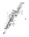
- FIG. 1a perspective view of a rifle, weapon, firearm, (automatic, semi-automatic or otherwise) 10 is illustrated.
- Rifle, weapon, firearm, etc. 10has a plurality of rails 12 .
- rails 12may be anyone of a MIL-STD-1913 rail, Weaver rail, NATO STANAG 4694 accessory rail or equivalents thereof.
- Rails 12are configured to allow a plurality of accessories 14 to the rifle 10 .
- Rails 12are mounted at the 12 o'clock, 3 o'clock, 6 o'clock and 9 o'clock positions with respect to a longitudinal or firing axis of the rifle and/or a barrel 16 of the rifle 10 .
- Accessories 14may be any one of telescopic sights, tactical sights, laser sighting modules, Global Positioning Systems (GPS) and night vision scopes or any type of sensor.
- the aforementioned accessoriesare merely an example of contemplated accessories for use with rifle or firearm 10 .
- a specific example of an attached accessoryis shown as personal data assistant (PDA) 140 or cellular telephone in FIG. 1 .
- accessories 14are items that require a source of power and/or require data communication with another component of the rifle or firearm 10 or a system in which rifle or firearm 10 is employed.
- one or more the accessoriesmay have its own power supply and may be able to communicate data independent of the firearm.
- Rail 12is a MIL-STD-1913 rail, such as a Weaver rail, NATO STANAG 4694 accessory rail or the like. Sliding over rail 12 is a powered or powering rail 18 .
- rail 12has a plurality of rail slots 20 and rail ribs 22 , which are utilized in receiving an accessory of another rail such as powering rail 18 .
- Powering rail 18comprises a plurality of rail slots 24 and rail ribs 26 in a configuration that allows for the mating of accessories with powering rail 18 .
- powering rail 18is mounted to rail 12 via a cross pin 28 or other device received within a pin hole 30 of powering rail 18 .
- the pin hole 30accepts the cross pin 28 so that the pin 28 locks and secures the rails 12 and 18 together.
- FIG. 1illustrates rail 18 secured to a top rail 12 of an upper receiver 31 of rifle or firearm 10 rail 18 can also be secured in additional locations such as the 3, 6 and 9 o'clock rail 12 locations. Still further, rail 18 may be secured to anyone or any combination of the 3, 6 and 9 o'clock rail 12 locations.
- powering rail 18may be formed into anyone of rails 12 such that a separate rail 18 is not necessary. In other words and in this embodiment, the rail 12 is now the networked power and/or data transmitting rail.
- the rail 18may also provide a path for transferring data from any or all of the accessories 14 to one or more processors carried in the firearm 10 .
- processorsmay be located, for example, in the rail 18 or the pistol grip 212 or both.
- a firearm 10includes a barrel 1 and has a plurality of powering rails 18 (e.g., 3 o'clock, 6 o'clock, 9 o'clock and 12 o'clock locations with respect to a longitudinal axis of the firearm 10 are provided, of course, any other locations are also contemplated).
- the powering rails 18are attached, in one embodiment, to rail 12 .
- Each of the powering rails 18are configured to transmit power to an associated accessory 14 via conductive couplings.
- the same or different couplingsmay also allow for the transmission of data though the rails 18 to/from the accessories.
- the couplingscan be any type of coupling including, for example, inductive couplings and/or galvanic couplings including direct contact between two conductive materials.
- one of data or poweris transmitted via inductive couplings and the other of data or power is transmitted via galvanic couplings. More detailed description of the powering rails 18 and the manner in which power/data may be transferred is described in one or more the patents/patent applications mentioned above.
- Each of the rails 18are also configured to communicate with a rail master control unit or processor 42 via a data bus, which in turn allows all of the accessories 14 to communicate information to other processors in the firearm.
- the firearm 10may further include a processor 51 disposed in the grip 212 ( FIG. 1 ) of the firearm. As discussed more fully below, the processor 51 may serve as the master control unit. In one embodiment, the processor 42 may be omitted.
- the processor 42may be referred to as a bus processor herein and it controls access to the data bus formed by the powering rails to allow for the processor 51 to communicate information to and from the accessories 14 .
- the bus processor 42may be located in either the upper or lower receiver of the firearm 10 or may be disposed in/on rails 12 or power rails 18 .
- processor 51is coupled via communication link 133 to a communication device 132 that may be worn, for example, in backpack or vest. This allows for the processor 51 to communicate with other devices 136 / 200 in the system as more fully described below.
- the communication link 133may be wired or wireless or a combination thereof.
- the communication device 132may communicate in any known manner including, but not limited to, rf communications, cellular communications, Bluetooth, and ZigBee and the communication path is generally shown as passing through a communication network 131 .
- the communication network 131can be any type of now known or later created network and may include one or more additional processors for routing or storing the information.
- the observer system 136is illustrated as a spotter scope 136 that may be able to determine the location of a potential target. This may include determining the location of the scope 136 and the distance/direction to the target for instance, by combining a GPS location of the scope 136 with distance from a laser range finder and means for determining pointing direction as discussed below this information may then be transferred form the scope 136 to the firearm 10 and then routed through the rails and a location of the target displayed on a map shown on an accessory 14 such as a PDA.
- firearm 10 of the system 130is a sniper rifle, which is networked or communicates with observer system 136 through the communication network 131 .
- the communication between the firearm and the scope 136may be direct point-to-point contact.
- one or more of the accessories 14may also communicate directly to the communication network 131 in any known manner including, but not limited to, rf communications, cellular communications, Bluetooth, and ZigBee and these communication devices may be any one of accessories 14 or peripheral device 132 which may be worn by an operator of one of the components.
- the communication networkis a wireless LAN network. The communication devices also being networked or in communication with other devices coupled to the powered rail(s) 18 .
- firearm 10 and observer system 136Although only two items (e.g., firearm 10 and observer system 136 ) are illustrated it is understood that numerous items (e.g., more than two) may be networked to communicate with each other. For example, multiple firearms 10 , observer systems 136 and numerous other devices or items may be networked through system 130 and data can be exchanged between any of the items through the communication network 131 . Each item may target, identify, or exchange data (either unique to that item or common between items) with respect to multiple targets, locations, persons, or other items.
- the spotter system 136may have a device 138 that communicates with an associated accessory 14 or device 140 illustrated in at least FIG. 1 .
- devices 138 and 140may be GPS, laser range finder, PDA or targeting devices capable of communicating (e.g., wireless or otherwise) with each other and thus exchanging data and information.
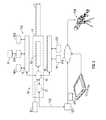
- FIG. 3shows a version of the system 130 capable of communication with and/or part of a battlefield management system (BMS) illustrated as tablet computer 200 .
- BMSbattlefield management system
- the BMScould be implanted on other types of devices.
- the PDA 140could be part of the system.
- a battlefield management systemis a system that integrates information acquired from multiple inputs and can be used coordinate movement/actions of multiple actors (e.g., soldiers).
- one of the accessories 14is coupled to an adapter 205 that allows it to communicate with the rail.
- the adapter 205could condition power into a form desired by the accessory.
- the adaptercould be utilized to convert power into a form or particular pin layout used by a PDA or scope.
- the adaptercould include formatting logic to convert PDA or scope data into a form conductive for transmission through the rail 18 .
- parallel datacould be converted into serial format.
- FIG. 20shows an example of an adapter 205 mounted to rail 18 .
- the illustrated adapter 205includes two peripheral ports 206 , 207 that can be used, for example, to connect to a PDA and a scope. Of course, the ports could connect to other devices such as cameras (still or video) or any other device.
- the system 130includes a sensor 220 capable of determining a bearing of firearm 10 .
- a sensormay be a compass or part of a GPS device or other device.
- the angular (bearing, pitch and roll) informationmay be determined from sensors contained in PDA 140 .
- the angular sensorsmay be formed by one or more rotationally sensitive sensors such as inclinometers, rate gyros, accelerometers and magnometer mounted on the firearm 10 .
- the firearm 10includes at least one set of angular sensors 222 to determine the inclination, roll and bearing with respect to the horizontal axis of the firearm.
- the processor 51may combine the data from the sensors (e.g., 220 , 222 ) as well as information from another other accessory 14 on the firearm and then cause it to be transmitted via communication device 132 to the battle management system 200 or any other observer system 136 . It shall be understood that any of the capabilities disclosed herein with respect to the rifle 10 may be applicable to the scope 136 or any other device included in system 130 .
- the processor 51collects data from the accessories 14 (herein, accessories will also include any sensor on the firearm) in either a polled or interrupt method via the data bus.
- the data buscan be either wired or wireless interfaces.
- the processor 51may utilize a real time clock to routinely interrogate accessories 14 at a predetermined schedule. During these predetermined intervals the processor 51 reads the data and stores it into memory.
- the datais tagged with a real time clock stamp to facilitate data processing.
- one or more of the accessories 14are interrupt driven. In such a case, an event causes the accessory 14 to send an interrupt to the processor 51 which, in turn, causes the processor 51 to collect data from the accessory 14 .
- the datais transmitted from communication device 132 to the tablet 200 , the observer system 136 or both. Further, either of observer 136 or the tablet 200 can send information back to the firearm 10 .
- processor 51draws power from the power supply 84 and may discover connected accessories 14 .
- the discoverymay include verifying that the accessory 14 is operable.
- the processor 51may configure the sensor based on its location on the firearm and function.
- the sensorscan be navigation, acoustic or optical devices. The sensors all communicate to the processor via the data bus and report sensor data and status.
- the navigation sensorscould be individual or integrated into a single package, and are GPS (military or commercial), accelerometer, rate gyro, magnometer (compass) or gyro scope and may sense and report in all three axial planes (x, y & z).
- the acoustic sensormay provide an acoustic signature of the environment around the firearm as well as of the firearm itself.
- the optical sensormay capture the optical spectrum in front of the weapon.
- the optical spectrumcould be the visual, infrared, thermal, Short Wave Length, Medium Wave Length and Long Wave Length, etc.
- the format of the data stored/transmitted by the processor 51can be varied and adapted to meet any preferred receiving performance.
- the processor 51may include the ability to synthesize the data from these accessories before transmitting the data. For example, if a camera is used to form a digital image of a target, the time and the position and orientation of the rifle 10 can be attached to that image before it is transmitted. Further, in some cases, the rifle 10 may include a video camera attached as an accessory. In such a case, the data (e.g., images) could be streamed in real-time with time/position data appended thereto or sent in periodic or interrupt driven intervals.
- the processor 51may include the ability to process the data collected from the accessories 14 .
- the processor 51may include instructions that allow it perform ballistics calculations, target range and angular offset calculation, and target tracking. Further, based on collected data, the number of shots taken, remaining ammunition, firearm performance and maintenance determinations and other firearm related calculations may be made.
- the accessories 14 /processor 51monitor the internal ballistic life cycle and internal mechanisms of the firearm. As a firearm's mechanisms wear or become fouled, previously recorded events can be compared to determine the percentage of difference. Dependent on the parameter be monitored, such comparisons may determine the usefulness of the firearm.
- map information related to an area in which the firearm 10 is, or in the future may be, locatedis provided to one or more of: microprocessor 84 , PDA 140 , and tablet 200 .
- the map informationmay be in the form of an overhead aerial view in one embodiment and may be received from any source including, but not limited to reconnaissance information taken by satellite or other overhead device such as a drone. Of course, publicly available maps could be used in one embodiment. Based on a GPS location of the firearm 10 , a portion of the map may be selected. Given the bearing of the firearm 10 , a view of the map in the region in front of the firearm 10 may be selected and displayed on the PDA 140 .
- the location of “friendlies”can be displayed on the maps as the table 200 includes information from all of the weapons in the system 130 and can place indicators on the map at those locations. Further, as an example, the location of a hostile party may be added to the map based, for example, the location of a friendly and a distance measured to the hostile by a laser range finder.
- the firearm 10includes an inclinometer as one of the accessories 14 . Assuming that ballistic information is known about a projectile (e.g., a bullet or grenade) that the firearm 10 (or an attachment thereto) fires, a projected impact point on the map be displayed.
- a projectilee.g., a bullet or grenade
- FIG. 4an example of a display 201 of PDA 140 is illustrated.
- the bearing informationshown by compass 203 ) described above can be used to position a possible impact location 202 of the projectile in along the y axis.
- information from an angular sensors and the ballistic informationcan be used to determine how far the projectile will travel and then, thus, determines the location of the impact location 202 .
- the impact location 202translates up on the map 201 .
- FIG. 5schematically illustrates communication between various components on a firearm as disclosed herein.
- the firearmincludes at least one rail 18 onto which several accessories 14 are coupled.
- the systemincludes three different communication channels shown as a low speed channel 502 , a medium speed channel 504 and a high speed channel 506 .
- the low speed channel 502extends from and allows communication between the master processor 76 and any of the accessories 14 .
- the low speed channel 502can be driven by a low speed transmitter/receiver 510 in processor 51 that includes selection logic 512 for selecting which of the accessories 14 to route the communication to.
- Each accessory 14includes low speed decoding/encoding logic 514 to receive and decode information received over the low speed channel 502 .
- the low speed decoding/encoding logic 514can also include the ability to transmit information from the accessories 14 as described above.
- the low speed channel 502carries data at or about 100 kB/s. Of course, other speeds could be used.
- the low speed channel 502passes through a coupling 520 .
- the coupling 520could be galvanic or via inductive coil pairs.
- the inductive coil paircould be replaced include a two or more core portions about which the coil pair is wound.
- the corescan be omitted and the inductive coil pair can be implemented as an air core transformer.
- the couplings 520are contained within the powering rail 18 . Of course, one or more of the portions of the coupling can be displaced from the rail 18 .
- the medium speed channel 504is connected to couplings 520 and shares them with low speed channel 502 .
- branches of the medium speed channel 504as illustrated in dashed lines.
- datacan be transferred on both the low speed channel 502 and the medium speed channel at the same time.
- the medium speed channel 504is used to transmit data between the accessories 14 .
- Both the low and medium speed channels 502 , 504can also be used to transmit data to or receive data from an accessory (e.g. a tether) not physically attached to the rail 18 as illustrated by element 540 .
- the connection between the processor 51can be either direct or through an optional inductive coil pair 520 ′.
- the optional inductive coil pair 520 ′couples power or data or both to processor 51 which may be located in or near a handle portion (e.g., pistol grip) of a firearm.
- the processor 51can include routing logic 522 that couples signals from one accessory to another based on information either received on the medium speed channel 504 .
- the signalcan be boosted or otherwise powered to ensure is can drive couplings 520 between the accessories.
- the accessory that is transmitting the datafirst utilizes the low speed channel 502 to cause the processor 51 sets the routing logic 522 to couple the medium speed channel 504 to the desired receiving accessory.
- the processor 51itself (or an element coupled to it) can be used to separate low and medium speed communications from one another and provide them to either the low speed transmitter/receiver 510 or the routing logic 522 , respectively.
- the medium speed channel 504carries data at 10 MB/s.
- FIG. 5also illustrates a high speed channel 506 .
- the high speed channel 506is formed by an optical data line and runs along at least a portion of the length of the rail 18 . For clarity, however, the high speed channel 506 is illustrated separated from the rail 18 .
- Accessories 14can include optical transmitter/receivers 542 for providing signals to and receiving signals from the high speed channel 506 .
- a high speed signal controller 532is provided to control data flow along the high speed channel 506 . It shall be understood that the high speed signal controller 532 can be located in any location and may be provided, for example, as part of the processor 51 .
- the high speed signal controller 532is an optical signal controller such as, for example, an optical router.
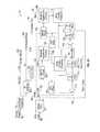
- FIG. 6shows a dataflow of information as it may be transferred according to one embodiment.
- Accessory data 1200 a , 1200 b and 1200 cis representative of data that may be transferred to or from accessories coupled to a rail system 1202 coupled to a firearm.
- the rail system 1202may be formed as herein described. Of course other rail systems capable of supporting one or more accessories on a firearm may be utilized.
- the rail system 1202may provide power to the accessories in one embodiment but that is not required.
- the rail system 18may also provide a physical conduit for transmitting data to and from the accessories.
- the data 1200 a - 1200 cpasses through a coupling 520 that provides for inductive or galvanic transfer of the data from the accessory to the communication pathway (e.g., bus) 1204 provided by the rail system 1202 .
- the communication pathwaye.g., bus
- Processor 42controls communication over the bus 1204 and as such may be referred to as a bus processor in one embodiment.
- the bus processor 42may be located in the rail system 1202 itself or in the upper or lower receiver of a firearm.
- the bus processormay be above to determine, in one embodiment, when an accessory is coupled to the rail system 1202 .
- another processore.g. processor 51
- the bus processor 42may be omitted.
- the bus processorcan allow, for example, for first accessory data 1200 a to be transferred to the processor 51 first, followed by data 1200 b and then 1200 c in one embodiment. Of course, any ordering a data can be provided for.
- the datareaches processor 51 and then transformed into an output data set 1200 d .
- the output data setis a compilation of portions of the data 1200 a - c .
- Output data set 1200 dcould also include additional information such as a time stamp. For example, assume data 1200 a is GPS data from a GPS device coupled to the rail system 1200 , data 1200 b is bearing information and data 1200 c is a target distance value. This data could be combined and time stamped to provide an accurate time sensitive location of a potential target. Data 1200 d may also include manipulated data as well. Regardless, data 1200 d is provided to computing device 200 (e.g., a battle management system).
- Computing device 200may also receive data from other battlefield devices (e.g., other rail systems) as generally indicated by data 1200 n .
- the computing devicetakes some or all of the data that it has received and may, in one embodiment create mission data 1200 e .
- This datais then transferred to processor 51 and subsequently provided to one or more of the accessories.
- An example(following from above) includes mission data 1200 e that includes a map showing all of the targets identified by any of the rifles and data 1200 e could be sent to any or all of the rifles that are connected to a particular network.
- the format and content of the each of the different data elements shown in FIG. 6may be platform agnostic in one embodiment so that the system 1202 may integrated into any preexisting or later developed battle management system.
- the rails 18can be used to deliver power and/or data to the accessories 14 .
- the power and/or datacan be transferred bidirectionally to and from the rail to the accessory inductively or via a direct electrical (galvanic) connection.
- FIG. 7a rail pinout is shown for rail 18 .
- the rail 18includes the rail slot 24 disposed between each of the rail ribs 26 .
- the rail slot 24includes either a power contact 32 or a ground contact 34 and either a first data contact DO or a second data contact D 1 .
- the power contact 32 and ground contact 34cannot be easily shorted together since they are in alternate slots 24 of powering rail 18 .
- an accessory 14is secured to the rail 18 in an incorrect fashion (e.g., backwards) no power/data will be provided as the accessory 14 will have a corresponding pattern configured to match the rail pin configuration as illustrated in FIG. 7 .
- two slots 24are required at a minimum to connect an accessory 14 to power, ground, and data (DO and Dl).
- FIG. 8A non-limiting example, the electronics contained in the powering rail 18 are shown in FIG. 8 .
- powere.g., 16.5 Volts or any other desirable voltage
- a sense resistor 38limits the short-circuit current to several milliamps. This is enough power to allow an accessory 14 to communicate to the system through an op amp 40 but not enough to take the system down if the power 32 and ground pins 34 are shorted.
- This communication to the accessory 14allows the system to detect if the accessory 14 is correctly installed on the rail 18 via the op amp and permitted to use full power.
- the systemcan provide full power by bypassing the sense resistor 38 .
- processor 42will bypass the sense resistor 38 by changing the conductive states of MOSFETs 44 and 46 .
- the sense resistor 38is also used to detect and measure the current supplied to the accessory 14 . If the power exceeds a predetermined threshold the accessory 14 can be returned to a low-power mode to protect the system's battery from being drained.
- an I2C busis used by the system to communicate with the rail processor 42 .
- the I2C (Inter-IC) busis a bi-directional two-wire serial bus that provides a communication link between integrated circuits (ICs).
- ICsintegrated circuits
- the 100 kb/s data channelalso called the low-speed data communication channel, is distributed within the system. Similarly to the conductive power transfer, the low speed channel is transferred conductively through the data pins. This is used to control the different accessories and transfer low speed data between the processor 51 and the accessories 14 .
- the 10 Mb/s data channelalso called the medium-speed data communication channel, is distributed within the system. It is sharing communication between rail slots with the low speed data channels and the data is transferred to the accessories in the same manner.
- the medium speed data channel pathprovides communication from one accessory to another accessory.
- the 500 Mb/s data channelalso called the high-speed data communication channel, is distributed within the system electrically and in one embodiment may be also optically. This channel may use a dedicated optical data port/data port (not shown).
- the rail 18provides a simple differential pair for all data communication between accessories.
- high-frequency narrow-band signaling between accessoriesmay be possible.
- Different frequenciesFrequency Division Multiplexing
- Future accessories with even higher bandwidth requirementscan be accommodated easily by using new frequencies.
- ZigBee signals at 700 MHzwill be used for low-speed communication (250 kbps) between the system and accessories.
- the differential signalingis used to ensure that the system does not emit any detectable signals and is less susceptible to any interference signals that may be present.
- the system shown in FIG. 8may employ a direct galvanic connection.
- a rail configurationdesigned to mount accessories such as sights, lasers and tactical lights is provided.
- This, as well as others rail configurations detailed herein,may be referred to as a Networked Powered Data System (NPDS) and is/are configured to provide power and data through a weapon coupled to accessories.
- NPDSNetworked Powered Data System
- the power and datamay be exchanged between the weapon and/or a user coupled to the weapon by a tether and in some applications the user is linked to a communications network that will allow data transfer to other users who may or may not also have weapons with rail configurations that are coupled to the communications network.
- the conductively powering rail 1014similar to the above embodiments comprises a plurality of rail slots 1020 , rail ribs 1022 and pins 1024 , in a configuration that allows for the mating of accessories with conductively powering rail 1014 .
- power and data transferis facilitated by a conductive connection or coupling via power and data pins 1015 embedded into the rail 1014 and power and data pins 1017 embedded into an accessory 1042 .
- Pins 1024 and 1025 in one embodimentare formed of metal.
- the pinsmay be formed of stainless steel pins of grade 430 and have configurations similar to those illustrated in the cross-sectional views illustrated in FIGS. 12 and 13 .
- pins 1024 , 1025connect to magnets 1046 , 1047 and trigger magnetic switch 1048 , 1051 to indicate to the conductively powering rail 1014 that an accessory 1042 has been connected.
- Pins 1024are offset from the center of conductively powering rail 1014 to ensure an accessory is mounted in the correct orientation, for example a laser accessory or flashlight accessory could not be mounted backward, and point in the users face as it would be required to connect to pins 1024 , to face away from the user of the firearm.
- pins 1024 and 1025are magnetized by magnets 1046 located within each portion of the accessory configured to be positioned over the ribs 1022 of the rail 1014 such that pins 1024 and 1025 are magnetized by the magnets 1046 .
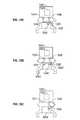
- FIG. 10Awhich is a cross sectional view of a portion of an accessory coupled to the rail, each pin 1025 is configured such that a first end 1045 is located on top of rib 1022 , an intermediate portion 1047 of pin 1025 is located above magnetic switch 1048 and a second end 1049 is also located on rib 1022 .
- the magnetized pin 1025causes magnetic switch 1048 to close to indicate to the conductively powering rail 1014 that an accessory has been connected to the data slot D.
- An example of a magnetic switchis a hall effect sensor.
- accessory 1042is provided with a magnetic accessory switch 1051 that is also closed by the magnetized pin 1025 which now returns to the surface of rib 1022 .
- the accessoryvia a signal from magnetic switch 1051 to a microprocessor resident upon the accessory will be able to determine that the accessory electronics 1053 associated with the switch 1051 in FIG. 10A is located above a data slot D and these electronics or equivalent items will be dedicated to data transfer only via conductive coupling. Accordingly, the data slot is different from the power slot ( FIG. 10C ) in that the associated pin is extended to become a fabricated clip to conduct the magnetic circuit from the accessory to the rail and back again to the accessory.
- the clipwill provide a magnetic field which, will activate the solid state switch or other equivalent item located within the rail on the one side and then will provide a path for the magnetic field on the other side of the rail reaching up to the accessory.
- the accessorywill have a solid state switch or equivalent item located at each slot position which, will be closed only if it is in proximity with the activated magnetic field of the data slot. This provides detection of the presence and location of the adjacent data slot.
- the accessory circuitry and softwareis configured to interface with the rail in terms of power and data communication.
- FIG. 10Cwhich is a cross sectional view of an another portion of the accessory secured to the rail
- the accessory electronics or other equivalent item 1053 associated with switch 1051 of the portion of the accessory illustrated in FIG. 10Cwill be able to determine that the accessory electronics 1053 associated with the switch 1051 in FIG. 10C is located above a power slot P and these electronics or equivalent items will be dedicated to power transfer only via conductive coupling.
- the complimentary accessorymay alternatively be configured to have a secondary electronics or equivalent item 1053 , magnet 1046 and switch 1051 for each corresponding rib/slot combination of the rail they are placed on such that the accessory will be able to determine if it has been placed on a data only D of power only P slot/rib combination according to the output of switch 1051 .
- the electronics associated with a rib containing pin 1024 or pin 1025may in one non-limiting embodiment be on either side of the associated rib and accordingly the electronics or equivalent item of the accessory associated with switch 1051 will be located in a corresponding location on the accessory.
- the data slotsare always forward (from a weapon view) from the rib having pin 1025 then the accessory will be configured to have the corresponding electronics forward from its corresponding switch 1051 .
- the configurationcould be exactly opposite. It being understood that the ribs at the end of the rail may only have one slot associated with it or the rail itself could possible end with a slot instead of a rib.
- the slots on either side of the rib having pin 1025may both be data slots as opposed to a single data slot wherein a data/power slot configuration may be as follows: . . . D, D, P, P, D, D, . . . as opposed to . . . D, P, P, D, P, P, P, P, P, P, P, P, P, P, P, P, P, P, P, P, P, P, P, P, P, P, P, P, P, P, P, P, P, P, P, P, P . . . for the same six slot configurations however, and depending on the configuration of the accessory being coupled to the rail a device may now have two data slots (e.g., secondary electronics on either side of switch 1051 that are now activated for data transfer).
- any one of numerous combinationsare contemplated to be within the scope of exemplary embodiments of the present invention and the specific configurations disclosed herein are merely provided as non-limiting examples.
- pins 1024can be offset from the center of conductively powering rail 1014 to ensure an accessory is mounted in the correct orientation.
- a pair of pins 1025are provided in the data slot and a pair of separate magnets (accessory magnet and rail magnet are used).
- the pinsare separated from each other and one pin 1025 , illustrated on the right side of the FIG., is associated with the accessory magnet 1046 and rail switch 1048 similar to the FIG. 10A embodiment however, the other pin 1025 illustrated on the left side of the FIG., is associated with the accessory switch 1051 and a separate rail magnet 1053 , now located in the rail. Operation of accessory switch 1051 and rail switch 1048 are similar to the previous embodiments.
- Power and data to and from the accessoryis provided by a plurality of power and data pins or contacts 1015 embedded into the rail 1014 and power and data pins or contacts 1017 embedded into an accessory 1042 . Accordingly, a galvanically coupled conductive rail power and communication distribution method for the rail system is provided.
- the exposed conductive metal rail contacts or contact surfaces 1035 and 1037 of pins 1015 and 1017are formed by coating copper pins with nickel or a nickel alloy for excellent durability and corrosion resistance to most environmental elements. Alternatively, they may be coated with a tungsten or a tungsten alloy. Accordingly and as described herein, power and/or data may be transferred bidirectionally to and from at least one accessory and the rail via direct contact of the conductive contact surfaces 1035 and 1037 of pins 1015 and 1017 . In one embodiment, the contact surfaces are round pads, pressed against each other to make good galvanic contact. In another embodiment, copper pins coated with nickel are used.
- the pads, both in the rail and the accessoryare permanently bonded to short posts of copper or other metal, that in turn, are electrically bonded to PCB substrates, rigid in the rail and flex in the accessory so that there is some give when the two surfaces are brought together. Accordingly, at least one of the pads in each contact pair provides some mechanical compliance, and in one embodiment the accessory is the item that have the mechanical compliance. Of course, this could also be in the rail or both.
- the pin/pad assembliesuse an X-section ring 1019 as a seal and compressible bearing 1021 , with the internal connection end attached to a flex PCB.
- the pin/pad constructionis shown in at least FIG. 17 .
- the padsprovide durability where the extreme G-forces of weapon firing vibrate the accessory attachment structure. The hardness of the touching contact surfaces ensures that little if any abrasion will take place as the surfaces slip minutely against each other.
- the pressure of the seal bearing (x-ring)will keep the pads firmly pressed together during the firing vibration, keeping electrical chatter of the contacts at minimal levels.
- the slot contactsare composed of small “pucks” that are press-fit or brazed to a metal pin.
- Nickel or nickel alloyexhibits a conductivity of roughly 5-10% that of copper and is considered a practical conductor. Assuming a good electrical bond between the puck and the pin, resistance introduced into the power path, accounting two traversals per round trip (Positive and Negative contacts).
- FIG. 16illustrates the rail side pins and caps installed in the rail at each slot position.
- FIG. 18also illustrates a rail side pin.
- Non-limiting examples of suitable copper alloys for the pinsare provided as follows: Copper Alloy 99.99% Cu Oxygen Free; 99.95% Cu 0.001% O; and 99.90% Cu 0.04% O of course, numerous other ranges are contemplated.
- Non-limiting examples of suitable Nickel to coat the pinsmay have: Electrical Conductivity: 9-15 kS/cm; Electrical Resistivity: 65-115 ⁇ -cm; Hardness: 490-570 Vickers Hardness; and Density: 8.1-8.3 g/cm 3
- Nickelis desired for its hardness and corrosion/oxidation resistance.
- the ultra-hard contact surfacewill ensure excellent abrasion endurance under the extreme acceleration stresses of weapon firing.
- unpolished contact surfacesmay be used.
- the hardness of nickel or nickel alloyhas virtually no malleability or sponginess, unlike softer metals like copper and lead. This means that two surfaces forced together will touch at the tallest micro-level surface features with little or no deformation of the peaks. This consequently small contact area will yield a resistance level that is much higher, possibly by orders of magnitude, over the expected theoretical resistance.
- other metals, alloys or materialsare contemplated for use with various embodiments of the present invention.
- the conductive networked power and data systemis a four-rail (top, bottom, left, right) system that distributes power and provides communication service to accessories that are mounted on any of the rails as well as the base of the grip.
- semiconductor elements associated with the power transfer pathwill be moved to locations external to the CNPDS. Presumably, those external elements can be viewed and managed as field replaceable items of far less cost and effort to replace than the rail system itself.
- Slot power controlis in one embodiment a desired feature for meeting power conservation goals, and the operation will be largely based on the magnetic activation principle mentioned above.
- each power slotis unconditionally OFF when there is no activating magnet present on its respective magnetic switch (e.g. Hall effect sensor).
- the Hall effect sensorpermits activation of the slot power but does not itself turn the power ON while the system is in normal operating state. The actual activation of the power switches is left to the MCU, allowing it to activate slots that are understood to be occupied, while keeping all others OFF.
- the first stateis normal operating mode, either during maintenance/configuration, or in actual use.
- the processore.g., processors 42 or 51
- I/O extension logiccontrols the power switch and the switch is only activated when commanded to do so.
- the second stateis defined as the Safe Power Only (SPO) mode, where the processor assumed to be incapacitated and is unable or not sane enough to control the slot power directly.
- SPOSafe Power Only
- the conditionis signaled to the rails from the processor through a failsafe watchdog hardware mechanism, using either the absence of logic supply or a separate SPO flag signal.
- the Hall effect sensor signaloverrides the logic control to activate the respective slot power unconditionally where an accessory is attached, assuming the system main power is also present.
- the primary consequence of this modeis loss of light load efficiency, since the processors would normally shut down the Hall effect sensors to conserve power. Accessory ON-OFF control under the SPO condition is expected to be through a manual switch in the accessory.
- the rails, and any other CNPDS element that may be found to exceed+85C under operations heavy usemay have a temperature sensor embedded into it and readable by the MCU. Still further, the rails may actually have multiple sensors, one per 6-slot segment. With this provision, the system software can take protective actions when the rail temperature exceeds +85 C.
- other weapon systemsmay feature an electromechanical trigger, the system can be allowed to automatically limit the generation of heat by pacing the rate of fire to some predetermined level.
- the sensor systemwould be necessarily engineered to the same reliability level of the Fire-by-Wire electronics.
- the battery packnow fully self-contained with charging system and charge state monitoring, will also contain a temperature sensor. Many battery chemistries have temperature limits for both charging and discharge, often with different temperature limits for each. The inclusion of a local temperature sensor in the battery pack will eliminate the need for the battery to depend on the CNPDS for temperature information, and thus allow the charge management to be fully autonomous.
- the CNPDSwill have slot position logic such that any accessory can be installed at any slot position on any of the rails, and can expect to receive power and communication access as long as the activation magnet is present.
- power and communicationwill not be shared among slot contacts, and will instead be arranged in a suitable power/comm. slot interleave on the rails.
- the CNPDSwill be configured such that the slots are groups of six, which defines the basic kernel of slot count per rail.
- all four railswill be built up in multiples of the six slot kernel, where Side rails will be 6 or 12 slots each, the top rail will be 24 or 30 slots, and the bottom rail will be 12 or 18 slots. This aggregation is done to provide logical grouping of internal rail control logic resources and does not impact slot occupation rules.
- the CNPDS direct galvanic couplingcan be engineered to provide over 15 Watts per slot on a single pair of contacts of course ranges greater or less than 15 Watts are contemplated.
- the CNPDSprovides a low impedance galvanic connection path between the battery pack and the contacts in the slots of the rails. Power at each slot is individually switched, using local magnetic sense activation combined with processor commands.
- CNPDS slot arrangement on each railwill be an interleave of power and data slots.
- a structure for the CNPDSwill aggregate groups of six slots into units that are concatenated to make up rail units of desired lengths.
- the management logic used to control the slot poweris based on the grouping, thus the longer top and bottom rails may have several management logic blocks.
- the CNPDSwill have an emergency power distribution mode in the event that the intelligent management and control systems (primarily the MCU) are incapacitated due to damage or malfunction. Under this mode, system control is assumed to be inoperative and the battery power is unconditionally available through individual slot Hall sensor activation.
- the intelligent management and control systemsprimarily the MCU
- the CNPDSwill have an alternative tether power connection which is a unidirectional input to the CNPDS, allowing the system to be powered and batteries to be charged from a weapon “Dock”.
- the Tether connectionprovides direct access to the lower receiver power connector, battery power port, and MCU power input.
- the OR-ing diode and any current limitingcan be implemented off-weapon at the tether power source.
- the tether sourceshould also contain inherent current limiting, same as the battery packs. These measures move protective components outside of the MCU to where they can be easily replaced in case of damage from power source malfunctions, rail slot overloads, or battle damage.
- the CNPDSwill have a reverse power, mode wherein the slots on the rails can accept DC power that could run the system.
- the CNPDSis can be used with high-density rechargeable chemistry batteries such as Lithium-Ion (Li-Ion) or any other equivalent power supply.
- the CNPDS communication infrastructuremay comprise two distributed networks between the rails and the processor 51 which may be located in the grip.
- the primary communication networkdefined as the data payload net, may be implemented as a 10Base2-like CSMA/CD line operation, supplying a 10 Mbit/sec Ethernet packet link from accessories on the rails to each other and/or to the Tether.
- the secondary networkis defined as the system management net on which the processors 42 / 51 are masters and the rails are slave devices. Both networks operate in parallel without any dependencies between them. Accessories will only ever receive the primary packet bus and all accessory bound control and data transactions will funnel through that connection.
- the following diagramdetails the basic structure of the two networks within the CNPDS.
- the communication structurehas a very similar architecture to the power distribution structure of the CNPDS.
- the six slot groupingwill similarly affect only the control subsystem aggregation and not impose limits on accessory slot alignment.
- the accessory base illustrated in FIG. 11can take on many forms with respect to footprint size. Depending on the power draw of the accessory, it may straddle several rail cores or one. An example of a three slot device is shown in the illustration of FIG. 11
- Accessory clampingcan be semi-permanent or quick release. In the semi-permanent scenario, this is achieved with a fork lock system illustrated in at least FIGS. 11-14 where the forks are pulled in to the rail with a thumb screw. Depending on the mass and geometry of the accessory, one or two fork assemblies may be required to securely mount it to the rail.
- a lever 1033is employed to effectively move the lock system (prong) into place and hold position.
- the weight and center of gravitywill define which type is used and how many are required for mechanical strength.
- electronic means of ensuring the accessory is installed correctlywill be employed.
- the systemwill identify the type and location of the accessory and provide power, communication or both.
- the accessory and the railboth have a 10 mm pitch such as to allow the lining up of accessory to rail slots and a shear area between accessory and rail to lock longitudinal relative movement between the two assemblies.
- the coupler 520could utilize inductive coupling to transmit power, data or both.
- a firearmthat includes an upper receiver; a lower receiver; a powered accessory mounted to a rail of the upper receiver; and an apparatus for inductively providing power and data to the powered accessory.
- datais exclusively provided to the powered accessory from one of a plurality of coils located within the rail.
- the powered accessorymay include a plurality of coils and be configured to determine when one of the plurality of coils of the powered accessory is adjacent to the one of the plurality of coils of the rail.
- a weapon or firearmhaving: an upper receiver; a lower receiver; a powered accessory mounted to a rail of the upper receiver; and an apparatus for inductively networking a processor of the powered accessory to a processor of the upper receiver and a processor of the lower receiver (e.g., in the grip).
- a method of networking a removable accessory of a weapon to a microcontroller of the weaponincluding the steps of: inductively transferring data between the accessory and the microcontroller via a first pair of coils exclusively dedicated to data transfer; inductively transferring power to the accessory via another pair of pair of coils exclusively dedicated to power transfer; and wherein the accessory is capable of determining the first pair of coils by magnetizing a pin located on the weapon.
- connection between an accessory and the inductively powering railis achieved by having electromagnets, which we refer to as “primary U-Cores” on the inductively powering rail and “secondary U-Cores” on the accessory.
- primary U-Coreson the inductively powering rail
- secondary U-Coreson the accessory.
- Embodimentsavoid the need for exposed electrical contacts, which may corrode or cause electrical shorting when submerged, or subjected to shock and vibration. This eliminates the need for features such as wires, pinned connections or watertight covers.
- Accessoriesmay be attached to various fixture points on the inductively powering rail and are detected by the firearm once attached.
- the firearmwill also be able to detect which accessory has been attached and the power required by the accessory.
- FIG. 21a cross section vertical view of a primacy U-Core and a secondary U-Core is shown.
- Primary U-Core 26provides inductive power to an accessory when connected to inductively powering rail 18 .
- Each of primary U-core 26 and secondary U-core 50are electromagnets.
- the wire wrappings 60 and 62provide an electromagnetic field to permit inductive power or data to be transmitted bi-directionally between inductively powering rail 18 and an accessory.
- Power/data sources for each primary U-core 26 or secondary U-core 50may be provided by a plurality of sources.
- a power sourcemay be within the firearm, it may be within an accessory or it may be provided by a source such as a battery pack contained in the uniform of the user that is connected to the firearm, or by a super capacitor connected to the system. These serve as examples of diverse power sources that may be utilize by embodiments of the invention.
- Accessory 14 in this exampleis a lighting accessory, having a forward facing lens 44 .
- Accessory 14connects to inductively powering rail 18 , through magnets 46 which engage pins 24 and trigger magnetic switch 48 to establish an electrical connection, via primary PCB 54 , to inductively powering rail 18 .
- PCBsPrinted Circuit Boards
- the PCB for the accessory 14is shown as accessory PCB 52 .
- the PCB for the inductively powering rail 18is shown as primary PCB 54 .
- FIG. 4a block diagram of the components of an inductively powered rail system is shown generally as 70 .
- System 70may be powered by a number of sources, all of which are controlled by master controller 72 .
- MCU 72could be either the bus processor 42 or processor 51 described above.
- Hot swap controller 74serves to monitor and distribute power within system 7 .
- Hot swap controller 74monitors power from multiple sources.
- the firstin one embodiment being one or more 18.5V batteries 78 contained within the system 70 , for example in the stock or pistol grip of a firearm. This voltage has been chosen as optimal to deliver two watts to each inductively powering rail slot 20 to which an accessory 14 is connected. This power is provided through conductive power path 82 .
- a second sourceis an external power source 80 , for example a power supply carried external to the system by the user.
- a third sourcemay come from accessories, which may have their own auxiliary power source 102 , i.e. they have a power source within them. When connected to the system, this feature is detected by master CPU 76 and the power source 102 may be utilized to provide power to other accessories through inductive power path 90 , should it be needed.
- conductive power path 82powers the inductively powering rail 18 while inductive power path 90 transfers power between the inductively powering rail 18 and accessories such as 14.
- Master CPU 76in one embodiment is a Texas Instrument model MSP430F228, a mixed signal processor, which oversees the management of system 70 . Some of its functions include detecting when an accessory is connected or disconnected, determining the nature of an accessory, managing power usage in the system, and handling communications between the rail(s), accessories and the user.
- FIG. 23Shown in FIG. 23 are three rails. The first being the main inductively powering rail 18 and side rail units 94 and 96 . Any number of rails may be utilized. Side rail units 94 and 96 are identical in configuration and function identically to inductively powering rail unit 18 save that they are mounted on the side of the firearm and have fewer inductively powered rail slots 20 . Side rail units 94 and 96 communicate with master CPU 76 through communications bus 110 , which also provides a path for conductive power. Communications are conducted through a control path 86 . Thus Master CPU 76 is connected to inductively powering rail 18 and through rail 18 to the microcontrollers 98 of side rails 94 and 96 .
- This connectionpermits the master CPU 76 to determine when an accessory has been connected, when it is disconnected, its power level and other data that may be useful to the user, such as GPS feedback or power level of an accessory or the system. Data that may be useful to a user is sent to external data transfer module 84 and displayed to the user. In addition data such as current power level, the use of an accessory power source and accessory identification may be transferred between accessories. Another example would be data indicating the range to a target which could be communicated to an accessory 14 such as a scope.
- Communicationsmay be conducted through an inductive control path 92 .
- an accessory 14such as an optical scope are connected to the system, it may communicate with the master CPU 76 through the use of inductive control paths 92 .
- Once a connection has been made between an accessory and an inductively powering rail 18 , 94 or 96 communicationmay be established from each rail via frequency modulation (for example) on an inductive control path 92 , through the use of primary U-cores 26 and secondary U-Cores 50 .
- Accessoriessuch as 14 in turn communicate with master CPU 76 through rails 18 , 94 or 96 by load modulation on the inductive control path 92 , for example.
- An example frequency modulationis Frequency Shift Key Modulation (FSK).
- a rail 18 , 94 , or 96sends power to an accessory 42 , by turning the power on and off to the primary U-core 26 and secondary U-core 50 . This is achieved by applying a frequency on the order of 40 kHz.
- different frequenciesmay be utilized. By way of example 40 kHz and 50 kHz may be used to represent 0 and 1 respectively.
- Types of information that may be sent by inductive control path 92may include asking the accessory information about itself, telling the accessory to enter low power mode, and asking the accessory to transfer power. Further, as described above, any information that the accessory may have may be provided to the CPU 76 and vice versa.
- load modulationthe inventors mean monitoring the load on the system 70 . If an accessory 14 decreases or increases the amount of power it requires then master CPU 76 will adjust the power requirements as needed.
- Accessory 104serves as an example of an accessory, being a tactical light. It has an external power on/off switch 106 , which many accessories may have as well as a safe start component 108 . Safe start component 108 serves to ensure that the accessory is properly connected and has appropriate power before turning the accessory on.
- Multi button pad 88may reside on the firearm containing system 70 or it may reside externally. Multi button pad 88 permits the user to turn accessories on or off or to receive specific data, for example the distance to a target or the current GPS location. Multi-button pad 88 allows a user to access features the system can provide through external data transfer module 84 .
- PCBPrimary Printed Circuit Board
- Hot swap controller 74serves to load the inductively powering rail 18 slowly. This reduces the amount of in rush current during power up. It also limits the amount of current that can be drawn from the inductively powering rail 18 .
- Conductive poweris distributed to two main components, the inductively powering rail slots 20 and the master CPU 76 residing on PCB 54 .
- Hot swap controller 74provides via feature 154 , voltage in the range of 14V to 22V which is sent to a MOSFET and transformer circuitry 156 for each inductively powering rail slot 20 on inductively powering rail 18 .
- Feature 158is a 5V switcher that converts battery power to 5V for the use of MOSFET drivers 160 .
- MOSFET drivers 160turn the power on and off to MOSFET and transformer circuitry 156 which provides the power to each primary U-Core 26 .
- Feature 162is a 3.3V Linear Drop Out Regulator (LDO), which receives its power from 5V switcher 158 .
- LDO 162provides power to master CPU 76 and supporting logic within each slot. Supporting logic is Mutiplexer 172 and D Flip Flops 176 .
- the Multiplexer 172 and the D Flip-Flops 176 , 177are utilized as a serial shift register. Any number of multiplexers 172 and D Flip-Flops 176 , 177 may be utilized, each for one inductively powered rail slot 20 . This allows master CPU 76 to determine which slots are enabled or disabled and to also enable or disable a slot.
- the multiplexer 172is used to select between shifting the bit from the previous slot or to provide a slot enable signal.
- the first D Flip Flop 176latches the content of the Multiplexer 172 and the second D Flip-Flop 177 latches the value of D Flip-Flop 177 if a decision is made to enable or disable a slot.
- Hall effect transistor 164detects when an accessory is connected to inductively powering rail 18 and enables MOSFET driver 160 .
- Feature 180refers to the primary U-Core 26 and the secondary U-Core 50 , establishing a power connection between inductively powering rail 18 and accessory 42 .
- High power ramp circuitry () 82slowly ramps the voltage up to high power load when power is turned on. This is necessary as some accessories such as those that utilize XEON bulbs when turned on have low resistance and they draw excessive current.
- High power load 184is an accessory that draws more than on the order of two watts of power.
- Full wave rectifier and DC/DC Converter 186rectifies the power from U-Cores 180 and converts it to a low power load 188 , for an accessory such as a night vision scope.
- Pulse shaper 190clamps the pulse fiam the U-Cores 180 so that it is within the acceptable ranges for microcontroller 98 and utilizes FSK via path 192 to provide a modified pulse to microcontroller 98 .
- Microcontroller 98utilizes a Zigbee component 198 via Universal Asynchronous Receiver Transmitter component (UART 196 ) to communicate between an accessory 42 and master controller 72 . Examples of the types of information that may be communicated would include asking the accessory for information about itself, instructing the accessory to enter low power mode or to transfer power.
- FIGS. 26-32a portion of the upper receiver 31 is illustrated secured to a lower receiver 70 of rifle, firearm or weapon 10 .
- the rifle, firearm or weapon 10has a buffer tube/receiver extension 72 .
- a butt stock portion 74is removably and movably secured to buffer tube/receiver extension 72 such that the location of butt stock portion 74 can be adjusted with respect to the buffer 2 /receiver extension 72 by for example, a latch means 76 configured to allow a spring biased protrusion to engage one of a plurality of detents 78 located on a buffer tube housing portion 80 that is configured to be received upon buffer tube/receiver extension 72 .
- a lower portion 82 of buffer tube housing portion 80is configured to removably receive and engage a battery pack or power supply 84 .
- a top surface 86 of the battery pack 84is provided with a plurality of contact pins 88 .
- Contact pins 88are configured to make contact with a plurality of contacts 90 located on lower portion 82 of buffer to housing portion 80 so that when the battery pack 84 is secured to buffer tube housing portion 80 power can be supplied to the networked powered rail system via a conductive path(s) 92 that extend from contacts 90 to a rail connector 94 located on the lower receiver 70 that is configured to contact a complementary connector 96 when the upper receiver 31 is secured to the lower receiver 70 .
- FIG. 31shows connectors 94 and 96 between the upper 31 and lower receiver 70 .
- Connector 96provides a conductive path to the processor 51 and other components of the powered rail 18 . This will allow power to be transferred from the battery pack 84 as well as data to be transferred to external tether connection 81 of the lower receiver. The location of the connection 81 may be moved to any desired location. In addition, connector 96 is configured to disengage when the upper receiver 31 is removed from the lower receiver 70 .
- the battery pack 84has a first contact feature 98 located at a rear portion of the battery pack 84 .
- First contact feature 98is configured to engage a rear abutment 100 of the buffer tube housing 80 .
- an alignment pin 102may also be provided to engage a rear alignment feature or opening 104 .
- the battery pack 84also has a second contact feature or front alignment feature 106 .
- the second contact feature or front alignment feature 106includes an opening 108 configured to receive a protrusion or feature 110 , located on the lower surface 82 of the buffer tube housing 80 . Accordingly, a user can secure battery pack or power supply 84 to the rifle, firearm or weapon 10 by simply causing the first contact feature 98 to engage the rear abutment 100 so that alignment pin 102 is received within alignment opening 104 and then the battery pack is pivoted upwardly in the direction of arrow 112 , so that protrusion or feature 110 of the second contact feature a front alignment feature 106 is received within opening 108 of the battery pack or power supply 84 .
- the battery pack or power supply 84is fixedly secured to the lower surface 82 of the buffer tube housing 80 via a retaining screw 114 that threateningly engages a threaded opening 116 of front alignment feature 106 .
- a head portion 118 of retaining screw 114is slightly larger than opening 108 of the battery pack or power supply 84 such that when the battery pack 84 is secured to the lower portion 82 of the buffer tube housing 80 head portion 118 prevents the battery pack 84 from being disengaged from the buffer tube housing 80 .
- a snap fit interfacecan be provided at either or both the contact feature 98 the second contact feature such that a user can simply snap battery pack 84 onto lower surface 82 of the buffer to the housing 80 .
- the upper surface of the battery pack 84has a plurality of contacts 88 configured to contact complementary contacts 90 located on the lower surface 82 of the buffer tube housing portion 80 .
- This conductive coupling or contactis approximately 90° off set with respect to a longitudinal axis 124 of the rifle 10 . This positioning prevents disengagement of contacts 88 and 90 due to recoil of the rifle, weapon or firearm in the directions of arrows 124 .
- contacts 88 and 90may comprise nickel coated materials.
- the contact surfaces of the contacts 88 and 90are coated with a nickel composite, which in one non-limiting embodiment may be a nano-coat blend of primarily nickel and other materials such as cobalt which will exhibit similar or superior properties to nickel.
- rail 18may be configured to be secured to any one of rails 12 of the rifle, firearm or weapon 10 .
- the configuration of rail 18may be incorporated into any one of the rails 12 of the rifle, firearm or weapon 10 thus negating the need for a separately attached rail 18 .
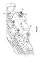
- FIGS. 38, 38A-38C and 39illustrates pin openings 209 in rail 18 it is understood that rail 18 may be configured without pin openings 209 as they are not necessary when the rail 18 is used with the accessory detection methods disclosed herein.
- Pin openings 209allow for the use of pins to be inserted into openings 209 , the pins are used with magnets and Hall effect sensors to detect the securement of an accessory secured to the powered rail 18 , wherein the detection method is any of those described in co-pending patent applications referenced above.
- the powered rail 18 of at least FIGS. 38-41Cmay also be used with the detection methods described in the above referenced pending patent applications (e.g. Hall effect sensors, magnets, and corresponding pins in addition to the data and power transfer pins) which are incorporated herein by reference thereto.
- detection methodsdescribed in the above referenced pending patent applications (e.g. Hall effect sensors, magnets, and corresponding pins in addition to the data and power transfer pins) which are incorporated herein by reference thereto.
- each slot 24has a pair of contacts one of which is either a power contact 32 or a ground contact 34 while the other one is one of the data contacts Dl or DO as described above.
- the rail 18is considered to have a plurality of elongated openings 210 that are configured to receive a portion of a non-conductive rail insert 211 or in other words an insert 211 formed from a non-conductive material. More particularly, each opening 210 is configured to receive a complementary shaped feature 214 of insert 211 .
- Each feature 214has a pair of openings 216 and 218 that are configured to receive one of the plurality of pins 1015 and their associated contacts 1035 that are used for the aforementioned power, ground and data contact points located within the slots 24 of the powered rail 18 .
- the openings 216 , 218 of the insert 211are configured such that the surface of the contacts 1035 of pins 48 are located on a surface within slots 24 so that they may be contacted by corresponding contacts 54 of an accessory 14 when it is secured to powered rail 18 .
- the insert 211is molded as a single component and each of the features 214 are secured to each other via a bridge member 215 . In other embodiments and depending on the length of rail 18 , two or more inserts 211 are used together.
- FIG. 39illustrates a bottom view of the rail 18 (e.g., the portion that is secured to rail 12 or is covered when rail 18 is secured to rail 12 ) wherein openings 210 are formed therein and a portion of the rail under rib 26 is removed to form a channel 217 .
- Channel 217is configured to receive bridge member 215 so that insert 211 can be secured to the rail 18 from its bottom side. Accordingly, the insert 211 with its associated contacts 1035 from pins 48 , which are secured to a printed circuit board, can be easily installed into the underside of rail 18 when insert 211 and its associated pins are secured to the printed circuit board illustrated in at least FIGS. 26A-26C .
- FIGS. 41A-41Cillustrate the insert 211 secured to a printed circuit board 221 which includes some of the necessary electronics for operating the powered rail.
- the insert 211is formed from an easily molded plastic or polymer material for example a high temperature resistant and/or chemically resistant polymer or equivalents thereof.
- a materialis a PEEK plastic or poly ether ether ketone or equivalent thereof.
- Poly ether ether ketone (PEEK)is an organic polymer thermoplastic in the polyaryletherketone (PAEK) family,
- the entire rail 18 or significant portions thereofcan be manufactured from a molded plastic or polymer material for example a high temperature resistant and/or chemically resistant polymer or equivalents thereof.
- a molded plastic or polymer materialfor example a high temperature resistant and/or chemically resistant polymer or equivalents thereof.
- a materialis a PEEK plastic or poly ether ether ketone or equivalent thereof.
- a polymer rail 18is contemplated.
- the polymer rail 18allows for a reduction of weight over an aluminum rail.
- the electronicsare assembled or secured to the rail from the bottom of the rail. Accordingly, the pins with nickel or nickel alloy contact in a polymer insert secured to the bottom of the rail does not compromise the strength of the rail.
Landscapes
- Engineering & Computer Science (AREA)
- General Engineering & Computer Science (AREA)
- Computer Networks & Wireless Communication (AREA)
- Signal Processing (AREA)
- Radar, Positioning & Navigation (AREA)
- Remote Sensing (AREA)
- Arrangements For Transmission Of Measured Signals (AREA)
- Position Fixing By Use Of Radio Waves (AREA)
Abstract
Description
Claims (25)
Priority Applications (9)
| Application Number | Priority Date | Filing Date | Title |
|---|---|---|---|
| US14/476,210US10477618B2 (en) | 2010-01-15 | 2014-09-03 | Networked battle system or firearm |
| AU2014390649AAU2014390649B2 (en) | 2014-04-07 | 2014-10-17 | A networked battle system or firearm |
| NZ725191ANZ725191A (en) | 2014-04-07 | 2014-10-17 | A networked battle system or firearm |
| US14/517,334US10470010B2 (en) | 2010-01-15 | 2014-10-17 | Networked battle system or firearm |
| EP14889015.5AEP3129740A4 (en) | 2014-04-07 | 2014-10-17 | A networked battle system or firearm |
| CA2945191ACA2945191C (en) | 2014-04-07 | 2014-10-17 | A networked battle system or firearm |
| PCT/CA2014/051006WO2015154161A1 (en) | 2014-04-07 | 2014-10-17 | A networked battle system or firearm |
| US14/808,535US10477619B2 (en) | 2010-01-15 | 2015-07-24 | Networked battle system or firearm |
| US15/165,125US20170010073A1 (en) | 2010-01-15 | 2016-05-26 | Networked battle system with heads up display |
Applications Claiming Priority (10)
| Application Number | Priority Date | Filing Date | Title |
|---|---|---|---|
| US12/688,256US9823043B2 (en) | 2010-01-15 | 2010-01-15 | Rail for inductively powering firearm accessories |
| US201161443085P | 2011-02-15 | 2011-02-15 | |
| US201161528728P | 2011-08-29 | 2011-08-29 | |
| US13/372,825US9891023B2 (en) | 2010-01-15 | 2012-02-14 | Apparatus and method for inductively powering and networking a rail of a firearm |
| US13/956,582US9921028B2 (en) | 2010-01-15 | 2013-08-01 | Apparatus and method for powering and networking a rail of a firearm |
| US13/968,882US9897411B2 (en) | 2010-01-15 | 2013-08-16 | Apparatus and method for powering and networking a rail of a firearm |
| US201361875468P | 2013-09-09 | 2013-09-09 | |
| US201461976157P | 2014-04-07 | 2014-04-07 | |
| US201462003006P | 2014-05-26 | 2014-05-26 | |
| US14/476,210US10477618B2 (en) | 2010-01-15 | 2014-09-03 | Networked battle system or firearm |
Related Parent Applications (1)
| Application Number | Title | Priority Date | Filing Date |
|---|---|---|---|
| US14/481,542Continuation-In-PartUS10337834B2 (en) | 2010-01-15 | 2014-09-09 | Networked battle system or firearm |
Related Child Applications (2)
| Application Number | Title | Priority Date | Filing Date |
|---|---|---|---|
| US14/481,542Continuation-In-PartUS10337834B2 (en) | 2010-01-15 | 2014-09-09 | Networked battle system or firearm |
| US14/517,334Continuation-In-PartUS10470010B2 (en) | 2010-01-15 | 2014-10-17 | Networked battle system or firearm |
Publications (2)
| Publication Number | Publication Date |
|---|---|
| US20150300786A1 US20150300786A1 (en) | 2015-10-22 |
| US10477618B2true US10477618B2 (en) | 2019-11-12 |
Family
ID=54321762
Family Applications (1)
| Application Number | Title | Priority Date | Filing Date |
|---|---|---|---|
| US14/476,210Active2036-06-20US10477618B2 (en) | 2010-01-15 | 2014-09-03 | Networked battle system or firearm |
Country Status (1)
| Country | Link |
|---|---|
| US (1) | US10477618B2 (en) |
Cited By (5)
| Publication number | Priority date | Publication date | Assignee | Title |
|---|---|---|---|---|
| US20210222995A1 (en)* | 2017-05-15 | 2021-07-22 | T-Worx Holdings, LLC | Power system for a firearm |
| US20230023146A1 (en)* | 2019-12-11 | 2023-01-26 | Fn Herstal S.A. | Mounting rail for firearm |
| US20230143306A1 (en)* | 2009-01-16 | 2023-05-11 | T-Worx Holdings, LLC | Accessory mount for rifle accessory rail, communication, and power transfer system - accessory attachment |
| US11716807B2 (en)* | 2021-12-09 | 2023-08-01 | Fieldpiece Instruments, Inc. | Power and communication handguard |
| US20240080911A1 (en)* | 2022-09-06 | 2024-03-07 | Science Applications International Corporation | Systems and Methods for Communicating Data in an Operational Environment |
Families Citing this family (32)
| Publication number | Priority date | Publication date | Assignee | Title |
|---|---|---|---|---|
| US10477619B2 (en) | 2010-01-15 | 2019-11-12 | Colt Canada Ip Holding Partnership | Networked battle system or firearm |
| US9921028B2 (en) | 2010-01-15 | 2018-03-20 | Colt Canada Ip Holding Partnership | Apparatus and method for powering and networking a rail of a firearm |
| US9823043B2 (en) | 2010-01-15 | 2017-11-21 | Colt Canada Ip Holding Partnership | Rail for inductively powering firearm accessories |
| US10470010B2 (en) | 2010-01-15 | 2019-11-05 | Colt Canada Ip Holding Partnership | Networked battle system or firearm |
| US10337834B2 (en)* | 2010-01-15 | 2019-07-02 | Colt Canada Ip Holding Partnership | Networked battle system or firearm |
| DK3165868T3 (en) | 2011-02-15 | 2018-11-26 | Colt Canada Ip Holding Partnership | Apparatus and method for inductive power supply and network connection of a firearm's rail |
| CA2881982C (en) | 2012-08-16 | 2020-10-13 | Colt Canada Corporation | Apparatus and method for powering and networking a rail of a firearm |
| WO2014160878A1 (en)* | 2013-03-27 | 2014-10-02 | Miller Craig M | Powered tactical rail (aka picatinny rail) system and method of using the same |
| US11408699B2 (en) | 2014-03-21 | 2022-08-09 | Armaments Research Company Inc. | Firearm usage monitoring system |
| DK3247969T3 (en)* | 2015-01-22 | 2020-11-09 | Colt Canada Ip Holding Partnership | SENSOR PACK FOR FIREARMS |
| US9964382B2 (en)* | 2015-11-15 | 2018-05-08 | George Stantchev | Target acquisition device and system thereof |
| US10876816B2 (en)* | 2015-11-16 | 2020-12-29 | Hookshottactical, Llc | Camera sight devices and rear viewing camera smart phone mount for a firearm |
| ITUB20160173A1 (en)* | 2016-01-27 | 2017-07-27 | Fabbrica Darmi Pietro Beretta S P A | GUIDE FOR FIRE WEAPONS |
| CA3093803A1 (en)* | 2016-02-03 | 2017-10-26 | VK Integrated Systems, Inc. | Firearm electronic system |
| US10113825B2 (en) | 2016-05-10 | 2018-10-30 | Kudzu Arms, Llc | Systems and methods for attaching a secondary firearm to a primary firearm |
| EP3555547A4 (en) | 2016-12-19 | 2020-09-16 | Savage Arms, Inc. | Semi-automatic shotgun and components thereof |
| US11879700B2 (en) | 2016-12-19 | 2024-01-23 | Savage Arms, Inc. | Semi-automatic shotgun and components thereof |
| US11561058B2 (en)* | 2017-01-27 | 2023-01-24 | Armaments Research Company Inc. | Weapon usage monitoring system with situational state analytics |
| US11125520B2 (en) | 2017-01-27 | 2021-09-21 | Armaments Research Company, Inc. | Firearm usage monitoring system providing alerts for ammunition resupply |
| US12018902B2 (en)* | 2017-01-27 | 2024-06-25 | Armaments Research Company Inc. | Weapon usage monitoring system having shot correlation monitoring based on user fatigue |
| US20240068761A1 (en) | 2017-01-27 | 2024-02-29 | Armaments Research Company, Inc. | Weapon usage monitoring system having predictive maintenance and performance metrics |
| US11293709B2 (en)* | 2017-01-27 | 2022-04-05 | Armaments Research Company, Inc. | Weapon usage monitoring system for initiating notifications and commands based on dashboard actions |
| CA3063897A1 (en) | 2017-05-15 | 2018-11-22 | T-Worx Holdings, LLC | System and method for networking firearm-mounted devices |
| US10341162B2 (en)* | 2017-09-12 | 2019-07-02 | Pacific Import Manufacturing, Inc. | Augmented reality gaming system |
| EP3372947B1 (en)* | 2018-01-22 | 2020-02-19 | Rade Tecnologías, S. L. | Weapon communication method and system |
| CA3156348A1 (en) | 2018-10-12 | 2020-04-16 | Armaments Research Company Inc. | Firearm monitoring and remote support system |
| US11627451B2 (en)* | 2019-01-21 | 2023-04-11 | T-Worx Holdings, LLC | Rail operating system |
| US20220341697A1 (en)* | 2021-04-21 | 2022-10-27 | T-Worx Holdings, LLC | Electrical power source for a firearm |
| US20220349676A1 (en)* | 2021-05-03 | 2022-11-03 | John Aron Maguire | Novel System And Methods For Incorporating Firearm Ammunition Temperature & Thermal Susceptibility To Improve Ballistic Calculator Algorithms And Fidelity |
| EP4544257A1 (en)* | 2022-06-23 | 2025-04-30 | Aimpoint AB | Sight mounting system, sight, and adapter plate |
| WO2024191798A1 (en)* | 2023-03-13 | 2024-09-19 | Lifelens Technologies, Inc. | Tracking and monitoring resource usage by subjects |
| US20250085080A1 (en)* | 2023-09-13 | 2025-03-13 | Wilcox Industries Corp. | Power and data retrofit for weapon accessory rail |
Citations (234)
| Publication number | Priority date | Publication date | Assignee | Title |
|---|---|---|---|---|
| US1950835A (en) | 1933-03-29 | 1934-03-13 | Walter Piotrowski | Firearm light |
| DE2251670A1 (en) | 1972-10-21 | 1974-05-02 | Duerrwaechter E Dr Doduco | Bonded carbide electrical contacts - contg. molybdenum/tungsten carbides in silver or copper, for improved electrical and mechanical abrasion resistance |
| US4533980A (en) | 1982-06-21 | 1985-08-06 | Hayes Lawrence S | Luminous gun sighting system |
| US5033219A (en) | 1990-02-06 | 1991-07-23 | Emerging Technologies, Inc. | Modular laser aiming system |
| US5142806A (en) | 1991-09-23 | 1992-09-01 | Swan Richard E | Universal receiver sleeve |
| US5237773A (en) | 1991-09-20 | 1993-08-24 | Claridge Hi-Tec Inc. | Integral laser sight, switch for a gun |
| US5345707A (en) | 1993-03-31 | 1994-09-13 | The United States Of America As Represented By The Secretary Of The Army | Interchangeable laser cavity cartridge |
| US5360949A (en) | 1993-06-30 | 1994-11-01 | Northern Telecom Limited | Printed circuit board |
| US5555662A (en) | 1993-06-08 | 1996-09-17 | Teetzel; James W. | Laser range finding apparatus |
| US5557872A (en) | 1995-05-25 | 1996-09-24 | Langner; F. Richard | Power supply for firearm accessories |
| US5654594A (en) | 1996-02-27 | 1997-08-05 | Laser Products Ltd. | Ergonomic electrical current switching systems |
| US5669174A (en) | 1993-06-08 | 1997-09-23 | Teetzel; James W. | Laser range finding apparatus |
| US5822905A (en) | 1994-02-23 | 1998-10-20 | Teetzel; James W. | Firearm hand grips for controlling an electronic module |
| US5826363A (en) | 1997-07-10 | 1998-10-27 | Knights Armament Company | Rail adapter handguard systems for firearms |
| US5831841A (en) | 1996-08-02 | 1998-11-03 | Diafuku Co., Ltd. | Contactless power distribution system |
| US6163131A (en) | 1998-04-02 | 2000-12-19 | The Procter & Gamble Company | Battery having a built-in controller |
| US6219952B1 (en) | 1999-01-25 | 2001-04-24 | Jonathan E. Mossberg | Magnetic tag firearm safety enhancement system |
| US6237271B1 (en) | 1996-07-23 | 2001-05-29 | Colt's Manufacturing Company, Inc. | Firearm with safety system having a communication package |
| US6412207B1 (en) | 1998-06-24 | 2002-07-02 | Caleb Clark Crye | Firearm safety and control system |
| US6430861B1 (en) | 2000-06-12 | 2002-08-13 | Tyler Ayers | Electronically controlled firearm |
| US20020174588A1 (en) | 2001-05-24 | 2002-11-28 | R.A. Brands, Llc | Firearm orientation and drop sensor system |
| US6490822B1 (en) | 2001-03-09 | 2002-12-10 | Richard E. Swan | Modular sleeve |
| US6499245B1 (en) | 2001-03-09 | 2002-12-31 | Richard E. Swan | Modular sleeve yoke |
| US6508027B1 (en) | 2001-10-02 | 2003-01-21 | Surefire, Llc | Accessory mounts for firearms |
| US6513251B2 (en) | 2001-01-11 | 2003-02-04 | Quarton, Inc. | Illuminable laser sight |
| US20030029072A1 (en) | 2001-08-13 | 2003-02-13 | Lewis Danielson | Apparatus and method for actuating a weapon accessory by a laser sighting beam |
| US20030074822A1 (en) | 2001-10-16 | 2003-04-24 | First Samco Inc. | Forearm handguard for a rifle |
| US20030106251A1 (en) | 2001-12-12 | 2003-06-12 | Surefire, Llc | Accessory mounts for shotguns and other firearms |
| US6618976B1 (en) | 2001-12-10 | 2003-09-16 | Richard E. Swan | Drop-in laser |
| US6622416B2 (en) | 2001-01-04 | 2003-09-23 | Surefire, Llc | Target and navigation illuminators for firearms |
| US20040121292A1 (en) | 2002-08-08 | 2004-06-24 | Chung Bobby Hsiang-Hua | Wireless data communication link embedded in simulated weapon systems |
| US6779288B1 (en) | 2003-05-29 | 2004-08-24 | Surefire, Llc | Accessory mounts for firearms |
| US6792711B2 (en) | 2002-06-17 | 2004-09-21 | Colt's Manufacturing Company, Inc. | Firearm adapter rail system |
| US20040198336A1 (en) | 2003-04-07 | 2004-10-07 | Jancic Dale Allen | Wireless controlled devices for a weapon and wireless control thereof |
| US20040241622A1 (en) | 2003-05-29 | 2004-12-02 | White Thompkins W. | Automated projectile delivery system |
| US20050000142A1 (en) | 2003-05-29 | 2005-01-06 | Surefire, Llc | Accessory mounts for firearms |
| US6847587B2 (en) | 2002-08-07 | 2005-01-25 | Frank K. Patterson | System and method for identifying and locating an acoustic event |
| US20050018041A1 (en) | 2003-07-21 | 2005-01-27 | Towery Clay E. | Electronic firearm sight, and method of operating same |
| US6849811B1 (en) | 2000-07-31 | 2005-02-01 | General Electric Company | Methods and apparatus for transfer switch |
| US20050033544A1 (en) | 2001-12-10 | 2005-02-10 | Brooks Colin Philip | Detectable components and detection apparatus for detecting such components |
| US6854206B2 (en) | 2003-06-24 | 2005-02-15 | T.D.I. Arms Systems, Ltd. | Rail connector and method |
| US6865599B2 (en) | 2001-09-04 | 2005-03-08 | Chenglin Zhang | Browser-to-browser, dom-based, peer-to-peer communication with delta synchronization |
| US20050109201A1 (en) | 2002-12-02 | 2005-05-26 | Giat Industries | Device to provide an electrical connection between a recoiling mass of a weapon and a fixed cradle |
| US6899539B1 (en) | 2000-02-17 | 2005-05-31 | Exponent, Inc. | Infantry wearable information and weapon system |
| CA2547081A1 (en) | 2003-11-24 | 2005-06-09 | Advanced Design Consulting Usa, Inc. | Device for collecting statistical data for maintenance of small-arms |
| US6918066B2 (en) | 2001-09-26 | 2005-07-12 | International Business Machines Corporation | Method and system for evaluating applications on different user agents |
| US6925744B2 (en) | 2003-05-13 | 2005-08-09 | Abrams Airborne Manufacturing, Inc. | Modular firearm buttstock |
| US6931775B2 (en) | 2002-06-05 | 2005-08-23 | Lockheed Martin Corporation | Remote control module for a vehicle |
| WO2005080908A2 (en) | 2003-09-12 | 2005-09-01 | Vitronics Inc. | Processor aided firing of small arms |
| CA2537839A1 (en) | 2002-09-06 | 2005-09-01 | Prototype Productions, Inc. | Tool apparatus |
| US20050204603A1 (en) | 2002-02-25 | 2005-09-22 | Sven-Erik Larsson | Gun accessory mounting device |
| US20050217161A1 (en) | 2004-03-31 | 2005-10-06 | Ra Brands, L.L.C. | Barrel accessory rail system |
| US20050241211A1 (en) | 2004-03-26 | 2005-11-03 | Swan Richard E | Modular panel system for attaching accessories to a firearm rail system |
| US20050241206A1 (en) | 2004-03-22 | 2005-11-03 | Wilcox Industries Corporation | Hand grip apparatus for firearm |
| WO2005109597A1 (en) | 2004-05-11 | 2005-11-17 | Splashpower Limited | Controlling inductive power transfer systems |
| US20050268521A1 (en) | 2004-06-07 | 2005-12-08 | Raytheon Company | Electronic sight for firearm, and method of operating same |
| US7007586B2 (en) | 2002-12-13 | 2006-03-07 | Giat Industries | Device providing an electrical connection between a weapon and a piece of ammunition |
| DE102004045753A1 (en) | 2004-09-21 | 2006-03-30 | Carl Walther Gmbh | Hand gun adapted to receive accessory, e.g. laser, has integrated power source and control device mounted in handgrip for powering and controlling accessory |
| US7059076B2 (en) | 2004-06-25 | 2006-06-13 | Abrahms Airborne Manufacturing | Firearm rail system |
| US7096619B2 (en) | 2004-02-17 | 2006-08-29 | Jackson Charles L | Equipment operator personalization device |
| US20060204935A1 (en) | 2004-05-03 | 2006-09-14 | Quantum 3D | Embedded marksmanship training system and method |
| US7121036B1 (en) | 2004-12-23 | 2006-10-17 | Raytheon Company | Method and apparatus for safe operation of an electronic firearm sight depending upon the detection of a selected color |
| US7124531B1 (en) | 2004-12-23 | 2006-10-24 | Raytheon Company | Method and apparatus for safe operation of an electronic firearm sight |
| US7131228B2 (en) | 2004-06-16 | 2006-11-07 | Colt Defense Llc | Modular firearm |
| US7144830B2 (en) | 2002-05-10 | 2006-12-05 | Sarnoff Corporation | Plural layer woven electronic textile, article and method |
| US20060288626A1 (en) | 2005-06-22 | 2006-12-28 | Surefire, Llc (A California Limited Liability Company) | Machine gun accessory mount adapter |
| US20070006509A1 (en) | 2004-07-06 | 2007-01-11 | Desomma Frank | Hand guard assembly for firearms |
| TW200715159A (en) | 2005-10-06 | 2007-04-16 | Chung Shan Inst Of Science | Method for integrating information and electronics of army command, control and management |
| US7216451B1 (en) | 2005-02-11 | 2007-05-15 | Troy Stephen P | Modular hand grip and rail assembly for firearms |
| US7231606B2 (en) | 2000-10-31 | 2007-06-12 | Software Research, Inc. | Method and system for testing websites |
| US20070150556A1 (en) | 2005-12-22 | 2007-06-28 | Kentarou Fukuda | Method for analyzing state transition in web page |
| US7243454B1 (en) | 2005-04-02 | 2007-07-17 | Tango Down, Llc | Integrated pressure switch pocket for a vertical fore grip |
| US20070216392A1 (en) | 2004-05-11 | 2007-09-20 | Stevens Michael C | Controlling Inductive Power Transfer Systems |
| WO2007107975A1 (en) | 2006-03-20 | 2007-09-27 | Itl Optronics Ltd. | Optical distance viewing device having positioning and/or map display facilities |
| USD556289S1 (en) | 2007-02-05 | 2007-11-27 | Herman Yu | Rail arrangement for firearm |
| US7316003B1 (en) | 2002-12-18 | 2008-01-01 | Oracle International Corp. | System and method for developing a dynamic web page |
| US20080010890A1 (en) | 2006-07-17 | 2008-01-17 | Vice Jack M | Mounted Isometric Controller |
| US20080039962A1 (en)* | 2006-05-23 | 2008-02-14 | Mcrae Michael W | Firearm system for data acquisition and control |
| US20080040965A1 (en) | 1998-07-02 | 2008-02-21 | Solinsky Kenneth S | Auxiliary device for a weapon and attachment thereof |
| US20080063400A1 (en) | 2006-05-12 | 2008-03-13 | Irobot Corporation | Method and Device for Controlling a Remote Vehicle |
| WO2008048116A1 (en) | 2006-10-16 | 2008-04-24 | Urban Voyage Limited | Monitoring engagement of a weapon |
| US20080092422A1 (en) | 2006-05-24 | 2008-04-24 | Daniel Defense, Inc. | Systems and Methods for Providing a Hand Guard and Accessory Mounting Device for a Firearm |
| US20080108021A1 (en) | 2004-11-24 | 2008-05-08 | Dynamic Animation Systems, Inc. | Instructor-lead training environment and interfaces therewith |
| US20080134562A1 (en) | 2006-11-01 | 2008-06-12 | Wilcox Industries Corp. | Modular flashlight apparatus for firearm |
| US20080170838A1 (en) | 2007-01-11 | 2008-07-17 | Wilcox Industries Corp. | Head-mounted video recording system |
| US20080190002A1 (en) | 2007-02-12 | 2008-08-14 | Steve Hines | Modular rail cover |
| US20080204361A1 (en) | 2007-02-28 | 2008-08-28 | Science Applications International Corporation | System and Method for Video Image Registration and/or Providing Supplemental Data in a Heads Up Display |
| US7421818B2 (en) | 2006-02-04 | 2008-09-09 | Lasermax, Inc. | Firearm mount with embedded laser sight |
| US20080219100A1 (en) | 2003-01-24 | 2008-09-11 | Shotspotter, Inc. | Systems and Methods Related to Identifying and/or Locating Weapon Fire Incidents |
| US20080216380A1 (en) | 2006-11-01 | 2008-09-11 | Teetzel James W | Three-Point Clamp for Firearm Mounting Rail |
| WO2008108818A2 (en) | 2006-09-28 | 2008-09-12 | Wolf Pac Technologies Corp | Power rail system |
| US7438430B2 (en) | 2004-04-29 | 2008-10-21 | Surefire, Llc | Light beam generator apparatus |
| US7461346B2 (en) | 2002-07-30 | 2008-12-02 | Sap Ag | Editing browser documents |
| US20080301994A1 (en) | 2007-04-09 | 2008-12-11 | Kevin Langevin | Firearm having a removable hand guard |
| US20090044439A1 (en) | 2007-08-16 | 2009-02-19 | Breaching Technologies, Inc. | Tactical foregrip assembly |
| US20090058361A1 (en) | 2007-06-01 | 2009-03-05 | Michael Sasha John | Systems and Methods for Wireless Power |
| US7523580B1 (en) | 2005-11-07 | 2009-04-28 | Jerome Benedict Tankersley | Handguard system integrated to a firearm |
| US7525203B1 (en) | 2005-08-11 | 2009-04-28 | Jeffrey Racho | Back-up electric power generator for electronic components attached to automatic firearms |
| US7551121B1 (en) | 2004-03-12 | 2009-06-23 | Oceanit Laboratories, Inc. | Multi-target-tracking optical sensor-array technology |
| US7559169B2 (en) | 2006-03-20 | 2009-07-14 | Asia Optical Co., Inc. | Firearm aiming and photographing compound apparatus and laser sight |
| US20090218884A1 (en) | 2005-06-28 | 2009-09-03 | Soar Roger J | Contactless Battery Charging Apparel |
| US7584569B2 (en) | 2005-08-19 | 2009-09-08 | Lasermax, Inc. | Target illuminating assembly having integrated magazine tube and barrel clamp with laser sight |
| US20090249216A1 (en) | 2008-03-28 | 2009-10-01 | International Business Machines Corporation | Interacting with multiple browsers simultaneously using linked browsers controlled from a primary browser interface |
| US20090255160A1 (en) | 2008-04-11 | 2009-10-15 | James Summers | Weapon control device |
| WO2009127354A2 (en) | 2008-04-16 | 2009-10-22 | Heckler & Koch Gmbh | Line arrangement, weapon component and weapon with said line arrangement |
| US7627975B1 (en) | 2007-02-12 | 2009-12-08 | Steve Hines | Electrified handguard |
| US20090305197A1 (en) | 2006-06-29 | 2009-12-10 | Korea Elecom | Apparatus and System For Simulating of Shooting a Grenade Launcher |
| WO2009151713A2 (en) | 2008-03-25 | 2009-12-17 | Raytheon Company | Systems and methods for communicating a firearm discharge event |
| US7640690B2 (en) | 2006-07-27 | 2010-01-05 | Steve Hines | Stock interface |
| WO2010004470A1 (en) | 2008-06-26 | 2010-01-14 | Fischer Connectors Holding S.A. | System with inbuilt electrical contacts |
| US20100031552A1 (en) | 2008-07-16 | 2010-02-11 | Lasermax, Inc. | Firearm assembly |
| US20100083553A1 (en) | 2008-10-03 | 2010-04-08 | Nanomaterials Discovery Corporation | Firearm Having Central Power Source and Integrated Data Bus to both Power and Control Multiple Accessories |
| US7698983B1 (en) | 2005-11-04 | 2010-04-20 | The United States Of America As Represented By The Secretary Of The Army | Reconfigurable fire control apparatus and method |
| US20100095574A1 (en) | 2008-10-19 | 2010-04-22 | Terrill Abst | Trigger activated switch |
| US7707762B1 (en) | 2005-01-05 | 2010-05-04 | Swan Richard E | Modular integrated rail assembly for firearms |
| US20100122485A1 (en) | 2008-11-20 | 2010-05-20 | Abrams Airborne Inc. | Firearm mounting mechanism |
| USD616521S1 (en) | 2009-04-23 | 2010-05-25 | Starnes John M | Rifle rail handguard with oblong cross-section |
| US20100126054A1 (en) | 2008-09-22 | 2010-05-27 | Daniel Defense, Inc. | Hand Guard Assembly for Securely Attaching to a Firearm |
| US20100154280A1 (en) | 2008-12-24 | 2010-06-24 | Surefire, Llc. | Machine gun accessory mount |
| US20100175293A1 (en) | 2009-01-11 | 2010-07-15 | Steve Hines | Two piece rail system for firearm |
| US20100181933A1 (en) | 2009-01-21 | 2010-07-22 | Altair Engineering, Inc. | Direct ac-to-dc converter for passive component minimization and universal operation of led arrays |
| US20100180485A1 (en) | 2009-01-16 | 2010-07-22 | Prototype Productions, Inc. | Rifle accessory rail, communication, and power transfer system - power distribution |
| US20100186278A1 (en) | 2009-01-28 | 2010-07-29 | Daniel Defense, Inc. | Handguard assembly and stanag mount adapter assembly |
| US20100192447A1 (en) | 2009-01-16 | 2010-08-05 | Prototype Productions, Inc. | Rifle accessory rail, communication, and power transfer system |
| US20100192443A1 (en) | 2009-01-16 | 2010-08-05 | Prototype Productions, Inc. | Rifle accessory rail, communication, and power transfer system - communication |
| US20100192446A1 (en) | 2009-02-05 | 2010-08-05 | Rubik Darian | Mounting rail |
| US20100196859A1 (en) | 2009-02-01 | 2010-08-05 | John David Saugen | Combat Information System |
| US20100192448A1 (en) | 2009-02-05 | 2010-08-05 | Rubik Darian | Mounting rail |
| US20100192444A1 (en) | 2009-01-16 | 2010-08-05 | Prototype Productions, Inc. | Rifle accessory rail, communication, and power transfer system - rail contacts |
| US7775150B2 (en) | 2006-02-09 | 2010-08-17 | Colt Defense Llc | Law enforcement carbine with one piece receiver |
| US20100218410A1 (en) | 2009-01-16 | 2010-09-02 | Prototype Productions, Inc. | Accessory mount for rifle accessory rail, communication, and power transfer system - accessory attachment |
| US7793452B1 (en) | 2008-01-22 | 2010-09-14 | Samson Manufacturing Corporation | Modular fore-end rail assembly with locking mechanism |
| US20100229448A1 (en) | 2007-12-14 | 2010-09-16 | Lasermax, Inc. | Removable foregrip with laser sight |
| CA2756018A1 (en) | 2009-03-19 | 2010-09-23 | Techni As | Voltage-free connector integrated in a weapon rail |
| US20100242332A1 (en) | 2004-03-22 | 2010-09-30 | Teetzel James W | Hand grip apparatus for firearm |
| US7818910B2 (en) | 2004-09-29 | 2010-10-26 | The United States Of America As Represented By The Secretary Of The Army | Weapon integrated controller |
| US20100275489A1 (en) | 2009-01-16 | 2010-11-04 | Prototype Productions, Inc. | Rifle accessory rail, communication, and power transfer system-battery pack |
| US20100279544A1 (en) | 2009-01-16 | 2010-11-04 | Prototype Productions, Inc. | Rugged low light reflectivity electrical contact |
| US20100281725A1 (en) | 2009-05-05 | 2010-11-11 | Awis Llc | System and Method for the Remote Measurement of the Ammunition Level, Recording and Display of the current level |
| CA2754869A1 (en) | 2009-05-15 | 2010-11-18 | The Otis Patent Trust | Integrated rail system and method for making and using same |
| CA2754852A1 (en) | 2009-05-15 | 2010-11-18 | The Otis Patent Trust | Integrated rail system and method for making and using same |
| US20110010979A1 (en) | 2009-07-16 | 2011-01-20 | Lasermax, Inc. | Mounting rail assembly for firearms |
| US20110031928A1 (en) | 2007-12-21 | 2011-02-10 | Soar Roger J | Soldier system wireless power and data transmission |
| US20110030257A1 (en) | 2009-08-04 | 2011-02-10 | Gwillim Jr Reese C | Device for indicating low ammunition in a firearm magazine |
| US20110036337A1 (en) | 2009-08-17 | 2011-02-17 | Freitag William C | Archery lighted release aid apparatus |
| US20110061284A1 (en) | 2009-01-16 | 2011-03-17 | Prototype Productions, Inc. | System for providing electrical power to accessories mounted on the powered rail of a weapon |
| US7909490B2 (en) | 2004-10-08 | 2011-03-22 | B/E Aerospace, Inc. | Lighting apparatus |
| US20110089894A1 (en) | 2007-12-21 | 2011-04-21 | Soar Roger J | Contactless battery charging apparel |
| US20110099876A1 (en) | 2009-11-05 | 2011-05-05 | Bentley James K | Accessory for a firearm |
| US7953369B2 (en) | 1999-06-21 | 2011-05-31 | Access Business Group International Llc | System and method for inductive power supply control using remote device power requirements |
| US20110126622A1 (en) | 2009-05-29 | 2011-06-02 | Turner Brian P | Apparatus and method for monitoring projectile emission and charging an energy storage device |
| US7954971B1 (en) | 2006-11-16 | 2011-06-07 | Blackhawk Industries Product Group Unlimited Llc | Offset mountable light accessory |
| US20110131858A1 (en) | 2009-02-05 | 2011-06-09 | Rubik Darian | Mounting rail |
| WO2011079233A2 (en) | 2009-12-23 | 2011-06-30 | Reset, Inc. | Communication and power distribution system and segmented rail adapter |
| US20110162251A1 (en) | 2006-02-04 | 2011-07-07 | Houde-Walter William R | Firearm mount with embedded sight |
| US20110162245A1 (en) | 2010-01-05 | 2011-07-07 | Ibrahim Kamal | Firearm Sensing Device and Method |
| US20110173865A1 (en) | 2010-01-15 | 2011-07-21 | Colt Canada Corporation | Rail for inductively powering firearm accessories |
| US7985527B2 (en) | 2006-12-21 | 2011-07-26 | Fujifilm Corporation | Conductive film and method of producing thereof |
| US7990147B2 (en) | 2008-06-18 | 2011-08-02 | Siemens Aktiengesellschaft | System and method for electrically contacting local coils with a signal processor remote therefrom in a magnetic resonance scanner |
| US8001715B2 (en) | 2005-04-26 | 2011-08-23 | Tactical Devices, Inc. | Illumination apparatus implementing non-lethal weapon |
| US8005995B2 (en) | 2007-08-16 | 2011-08-23 | Micron Technology, Inc. | Command interface systems and methods |
| US20110239354A1 (en) | 2010-02-02 | 2011-10-06 | Wilcox Industries Corp. | Helmet mounting system and mounting shoe interface |
| US20110252741A1 (en) | 2005-04-07 | 2011-10-20 | Prototype Productions, Inc. | Structural systems |
| US8042967B2 (en) | 2006-01-16 | 2011-10-25 | Koninklijke Philips Electronics N.V. | Lamp module and lighting device comprising such a lamp module |
| US20110264257A1 (en) | 2005-06-10 | 2011-10-27 | Prototype Productions, Inc. | Closed-loop cnc machine system and method |
| US20110271822A1 (en) | 2010-05-04 | 2011-11-10 | Makor Issues And Rights Ltd. | Automatic Real Time Command and Control System |
| US8063773B2 (en) | 2003-01-24 | 2011-11-22 | Shotspotter, Inc. | Systems and methods of directing a camera to image weapon fire |
| US20110283586A1 (en) | 2010-05-21 | 2011-11-24 | Laurent Scallie | System and method for weapons instrumentation technique |
| US20110283585A1 (en) | 2009-01-16 | 2011-11-24 | Prototype Productions, Inc. | System for providing electrical power to accessories mounted on the powered rail of a weapon |
| US20110306251A1 (en) | 2010-06-14 | 2011-12-15 | Tyco Electronics Corporation | Connector with a laterally moving contact |
| WO2011162245A1 (en) | 2010-06-23 | 2011-12-29 | 住友重機械工業株式会社 | Injection molding machine and power source regeneration converter |
| US8091265B1 (en) | 2007-01-10 | 2012-01-10 | Wilcox Industries Corp. | Floating rail system for firearm |
| US20120021385A1 (en) | 2006-11-24 | 2012-01-26 | Trex Enterprises Corp. | Celestial weapons orientation measuring system |
| US20120085331A1 (en) | 2008-08-22 | 2012-04-12 | Lang Russell W | Systems and methods of accessory mounting |
| US20120097741A1 (en) | 2010-10-25 | 2012-04-26 | Karcher Philip B | Weapon sight |
| US20120125189A1 (en) | 2010-11-22 | 2012-05-24 | DM Innovations | Firearm accessory part with tracking capability |
| US20120125092A1 (en) | 2010-11-22 | 2012-05-24 | DRS Technologies Canada, Ltd | Muzzle velocity sensor |
| US20120131837A1 (en) | 2009-01-16 | 2012-05-31 | Prototype Productions, Inc. | Rail contacts for accessories mounted on the powered rail of a weapon |
| US20120144716A1 (en) | 2009-01-16 | 2012-06-14 | Prototype Productions, Inc. | Communication and control of accessories mounted on the powered rail of a weapon |
| US20120180363A1 (en) | 2011-01-18 | 2012-07-19 | Prototype Productions, Inc. | Apparatus for mounting accessories on the accessory rail of a weapon |
| US20120192476A1 (en) | 2010-01-15 | 2012-08-02 | David Walter Compton | Apparatus and method for inductively powering and networking a rail of a firearm |
| US20120214137A1 (en)* | 2004-10-12 | 2012-08-23 | John Goree | Network weapon system and method |
| US8251288B2 (en) | 2007-10-16 | 2012-08-28 | Raytheon Company | Network-centric targeting |
| US20120233901A1 (en) | 2009-04-24 | 2012-09-20 | In Woo Kim | Firearm having dual barrels |
| US8311757B2 (en) | 2007-08-14 | 2012-11-13 | American Gnc Corporation | Miniaturized smart self-calibration electronic pointing method and system |
| US20120317706A1 (en) | 2011-03-14 | 2012-12-20 | Revision Military S.A.R.L. | Ballistic and Impact Protective Military Helmet Assembly |
| US8336776B2 (en) | 2010-06-30 | 2012-12-25 | Trijicon, Inc. | Aiming system for weapon |
| US8371729B2 (en) | 2004-11-15 | 2013-02-12 | Streamlight, Inc. | Light with keying arrangement mountable on a mounting rail |
| US20130047486A1 (en) | 2011-08-25 | 2013-02-28 | Leapers, Inc. | Adapter |
| US20130047482A1 (en) | 2011-08-23 | 2013-02-28 | Tyco Electronics Corporation | Communication connector system for a weapon |
| US20130061509A1 (en) | 2011-09-09 | 2013-03-14 | Lasermax, Inc. | Target marking system |
| US20130104439A1 (en) | 2011-11-01 | 2013-05-02 | Steve Hines | Powering firearm accessories with a false battery |
| US20130104438A1 (en) | 2011-11-01 | 2013-05-02 | Steve Hines | Battery adaptive device |
| US20130105579A1 (en)* | 2011-10-27 | 2013-05-02 | Harris Corporation | Single click fire control and visualization for small unit operations |
| US20130185978A1 (en) | 2012-01-24 | 2013-07-25 | Prototype Productions, Inc. | Communication and control of accessories mounted on the powered rail of a weapon |
| US8495945B1 (en) | 2010-01-06 | 2013-07-30 | The United States Of America As Represented By The Secretary Of The Navy | Weapon and weapon station system and method for loading, testing, targeting, and/or launching a weapon |
| WO2013120015A1 (en) | 2012-02-10 | 2013-08-15 | Reset Engineering, Llc. | Rail adapter accessory power protection circuit |
| US20130286239A1 (en) | 2012-04-30 | 2013-10-31 | Trackingpoint, Inc. | Rifle Scope with Video Output Stabilized Relative to a Target |
| US20130329211A1 (en) | 2012-06-07 | 2013-12-12 | Trackingpoint, Inc. | Target-Correlated Electronic Rangefinder |
| US20130337415A1 (en)* | 2012-06-16 | 2013-12-19 | Tony Huet | Firearm training system |
| US20130344461A1 (en) | 2012-06-26 | 2013-12-26 | Selso Tello | Universal Firearm Marksmanship System |
| US20140007485A1 (en) | 2012-07-03 | 2014-01-09 | Enrique Castejon, SR. | Wireless Remote Aiming Systems |
| US20140028856A1 (en) | 2011-03-28 | 2014-01-30 | Smart Shooter Ltd. | Firearm, aiming system therefor, method of operating the firearm and method of reducing the probability of missing a target |
| WO2014026274A1 (en) | 2012-08-15 | 2014-02-20 | Redwood Vernon | Promoter system and method for processing product and service data |
| US20140047754A1 (en) | 2010-01-15 | 2014-02-20 | David Walter Compton | Apparatus and method for powering and networking a rail of a firearm |
| US20140059911A1 (en) | 2012-08-30 | 2014-03-06 | Tycon Electronics Corporation | Powered rail system for a weapon |
| US8668496B2 (en) | 2012-02-08 | 2014-03-11 | Troy Nolen | Training system |
| US20140130392A1 (en) | 2012-10-16 | 2014-05-15 | Tyco Electronics Corporation | Communication connector system for a weapon |
| US8739672B1 (en) | 2012-05-16 | 2014-06-03 | Rockwell Collins, Inc. | Field of view system and method |
| US20140184476A1 (en) | 2012-12-31 | 2014-07-03 | Trackingpoint, Inc. | Heads Up Display for a Gun Scope of a Small Arms Firearm |
| US8826575B2 (en) | 2008-02-27 | 2014-09-09 | Robert Ufer | Self calibrating weapon shot counter |
| US20140360081A1 (en) | 2013-06-07 | 2014-12-11 | John Hancock Lupher | Precision Guided Firearm With Hybrid Sensor Fire Control |
| US20140378088A1 (en) | 2013-06-25 | 2014-12-25 | Qualcomm Incorporated | Wiretapping Firearms Through a Wireless Network |
| US20150020427A1 (en) | 2010-01-15 | 2015-01-22 | David Walter Compton | Apparatus and method for powering and networking a rail of a firearm |
| US20150026588A1 (en) | 2012-06-08 | 2015-01-22 | Thales Canada Inc. | Integrated combat resource management system |
| US20150041538A1 (en) | 2012-02-09 | 2015-02-12 | Wilcox Industries Corp. | Weapon video display system employing smartphone or other portable computing device |
| WO2015031993A1 (en) | 2013-09-09 | 2015-03-12 | Colt Canada Corporation | A network of intercommunicating battlefield devices |
| US9010002B2 (en) | 2013-02-01 | 2015-04-21 | Liviu Popa-Simil | Method and accessory device to improve performances of ballistic throwers |
| US20150108215A1 (en) | 2013-02-17 | 2015-04-23 | Smart Shooter Ltd. | Firearm aiming system with range finder, and method of acquiring a target |
| US20150176949A1 (en) | 2013-12-24 | 2015-06-25 | Deepak Varshneya | Electro-optic system for crosswind measurement |
| US9151564B1 (en) | 2006-08-15 | 2015-10-06 | Triggermaster, Inc. | Firearm trigger pull training system and methods |
| US20150285593A1 (en) | 2010-01-26 | 2015-10-08 | Ehud DRIBBEN | Monitoring shots of firearms |
| US20150285599A1 (en) | 2010-01-15 | 2015-10-08 | Warren Downing | Networked battle system or firearm |
| US20150345906A1 (en) | 2013-12-24 | 2015-12-03 | Deepak Varshneya | Electro-optic system for crosswind measurement |
| US20150345887A1 (en) | 2014-05-27 | 2015-12-03 | Israel Weapon Industries (I.W.I) Ltd. | Apparatus and method for improving hit probability of a firearm |
| US20150369554A1 (en) | 2014-06-18 | 2015-12-24 | Centinel Solutions, Inc. | Firearm-mounted camera device with networked control and administration system and method |
| US20160025462A1 (en) | 2010-01-15 | 2016-01-28 | Warren Downing | Networked battle system or firearm |
| US20160033221A1 (en) | 2013-03-15 | 2016-02-04 | Jacob Stewart Schmehl | Firearm accessory |
| US20160084617A1 (en) | 2014-09-19 | 2016-03-24 | Philip Lyren | Weapon Targeting System |
| US20160169627A1 (en) | 2013-05-09 | 2016-06-16 | Shooting Simulator, Llc | System and method for marksmanship training |
| US20160216082A1 (en) | 2015-01-22 | 2016-07-28 | Colt Canada Corporation | Sensor pack for firearm |
| US20160223278A1 (en) | 2013-10-24 | 2016-08-04 | Alfa Yuta, Prompting, Development And Advanced Technology Ltd | System, device and method for the prevention of friendly fire incidents |
| US20160254462A1 (en) | 2009-08-31 | 2016-09-01 | Udc Ireland Limited | Material For Organic Electroluminescence Device And Organic Electroluminescence Device |
| US20160316128A1 (en) | 2014-01-03 | 2016-10-27 | Flir Systems, Inc. | Camera system |
- 2014
- 2014-09-03USUS14/476,210patent/US10477618B2/enactiveActive
Patent Citations (296)
| Publication number | Priority date | Publication date | Assignee | Title |
|---|---|---|---|---|
| US1950835A (en) | 1933-03-29 | 1934-03-13 | Walter Piotrowski | Firearm light |
| DE2251670A1 (en) | 1972-10-21 | 1974-05-02 | Duerrwaechter E Dr Doduco | Bonded carbide electrical contacts - contg. molybdenum/tungsten carbides in silver or copper, for improved electrical and mechanical abrasion resistance |
| US4533980A (en) | 1982-06-21 | 1985-08-06 | Hayes Lawrence S | Luminous gun sighting system |
| US5033219A (en) | 1990-02-06 | 1991-07-23 | Emerging Technologies, Inc. | Modular laser aiming system |
| US5237773A (en) | 1991-09-20 | 1993-08-24 | Claridge Hi-Tec Inc. | Integral laser sight, switch for a gun |
| US5142806A (en) | 1991-09-23 | 1992-09-01 | Swan Richard E | Universal receiver sleeve |
| US5345707A (en) | 1993-03-31 | 1994-09-13 | The United States Of America As Represented By The Secretary Of The Army | Interchangeable laser cavity cartridge |
| US5555662A (en) | 1993-06-08 | 1996-09-17 | Teetzel; James W. | Laser range finding apparatus |
| US5669174A (en) | 1993-06-08 | 1997-09-23 | Teetzel; James W. | Laser range finding apparatus |
| US5360949A (en) | 1993-06-30 | 1994-11-01 | Northern Telecom Limited | Printed circuit board |
| US5822905A (en) | 1994-02-23 | 1998-10-20 | Teetzel; James W. | Firearm hand grips for controlling an electronic module |
| US5557872A (en) | 1995-05-25 | 1996-09-24 | Langner; F. Richard | Power supply for firearm accessories |
| US5654594A (en) | 1996-02-27 | 1997-08-05 | Laser Products Ltd. | Ergonomic electrical current switching systems |
| US6237271B1 (en) | 1996-07-23 | 2001-05-29 | Colt's Manufacturing Company, Inc. | Firearm with safety system having a communication package |
| US5831841A (en) | 1996-08-02 | 1998-11-03 | Diafuku Co., Ltd. | Contactless power distribution system |
| US5826363A (en) | 1997-07-10 | 1998-10-27 | Knights Armament Company | Rail adapter handguard systems for firearms |
| US6163131A (en) | 1998-04-02 | 2000-12-19 | The Procter & Gamble Company | Battery having a built-in controller |
| US6412207B1 (en) | 1998-06-24 | 2002-07-02 | Caleb Clark Crye | Firearm safety and control system |
| US20080040965A1 (en) | 1998-07-02 | 2008-02-21 | Solinsky Kenneth S | Auxiliary device for a weapon and attachment thereof |
| US6219952B1 (en) | 1999-01-25 | 2001-04-24 | Jonathan E. Mossberg | Magnetic tag firearm safety enhancement system |
| US7953369B2 (en) | 1999-06-21 | 2011-05-31 | Access Business Group International Llc | System and method for inductive power supply control using remote device power requirements |
| US6899539B1 (en) | 2000-02-17 | 2005-05-31 | Exponent, Inc. | Infantry wearable information and weapon system |
| US6430861B1 (en) | 2000-06-12 | 2002-08-13 | Tyler Ayers | Electronically controlled firearm |
| US6849811B1 (en) | 2000-07-31 | 2005-02-01 | General Electric Company | Methods and apparatus for transfer switch |
| US7231606B2 (en) | 2000-10-31 | 2007-06-12 | Software Research, Inc. | Method and system for testing websites |
| US6622416B2 (en) | 2001-01-04 | 2003-09-23 | Surefire, Llc | Target and navigation illuminators for firearms |
| US6513251B2 (en) | 2001-01-11 | 2003-02-04 | Quarton, Inc. | Illuminable laser sight |
| USRE40216E1 (en) | 2001-03-09 | 2008-04-08 | Swan Richard E | Modular sleeve |
| USRE39465E1 (en) | 2001-03-09 | 2007-01-16 | Swan Richard E | Modular sleeve yoke |
| US6499245B1 (en) | 2001-03-09 | 2002-12-31 | Richard E. Swan | Modular sleeve yoke |
| US6490822B1 (en) | 2001-03-09 | 2002-12-10 | Richard E. Swan | Modular sleeve |
| US20020174588A1 (en) | 2001-05-24 | 2002-11-28 | R.A. Brands, Llc | Firearm orientation and drop sensor system |
| US20030029072A1 (en) | 2001-08-13 | 2003-02-13 | Lewis Danielson | Apparatus and method for actuating a weapon accessory by a laser sighting beam |
| US6865599B2 (en) | 2001-09-04 | 2005-03-08 | Chenglin Zhang | Browser-to-browser, dom-based, peer-to-peer communication with delta synchronization |
| US6918066B2 (en) | 2001-09-26 | 2005-07-12 | International Business Machines Corporation | Method and system for evaluating applications on different user agents |
| US6508027B1 (en) | 2001-10-02 | 2003-01-21 | Surefire, Llc | Accessory mounts for firearms |
| US20030074822A1 (en) | 2001-10-16 | 2003-04-24 | First Samco Inc. | Forearm handguard for a rifle |
| US6618976B1 (en) | 2001-12-10 | 2003-09-16 | Richard E. Swan | Drop-in laser |
| US20050033544A1 (en) | 2001-12-10 | 2005-02-10 | Brooks Colin Philip | Detectable components and detection apparatus for detecting such components |
| US20030106251A1 (en) | 2001-12-12 | 2003-06-12 | Surefire, Llc | Accessory mounts for shotguns and other firearms |
| US7421817B2 (en) | 2002-02-25 | 2008-09-09 | Surefire, Llc | Gun accessory mounting device |
| US20050204603A1 (en) | 2002-02-25 | 2005-09-22 | Sven-Erik Larsson | Gun accessory mounting device |
| US7144830B2 (en) | 2002-05-10 | 2006-12-05 | Sarnoff Corporation | Plural layer woven electronic textile, article and method |
| US6931775B2 (en) | 2002-06-05 | 2005-08-23 | Lockheed Martin Corporation | Remote control module for a vehicle |
| US6792711B2 (en) | 2002-06-17 | 2004-09-21 | Colt's Manufacturing Company, Inc. | Firearm adapter rail system |
| US7461346B2 (en) | 2002-07-30 | 2008-12-02 | Sap Ag | Editing browser documents |
| US6847587B2 (en) | 2002-08-07 | 2005-01-25 | Frank K. Patterson | System and method for identifying and locating an acoustic event |
| US20040121292A1 (en) | 2002-08-08 | 2004-06-24 | Chung Bobby Hsiang-Hua | Wireless data communication link embedded in simulated weapon systems |
| CA2537839A1 (en) | 2002-09-06 | 2005-09-01 | Prototype Productions, Inc. | Tool apparatus |
| US20050109201A1 (en) | 2002-12-02 | 2005-05-26 | Giat Industries | Device to provide an electrical connection between a recoiling mass of a weapon and a fixed cradle |
| US7007586B2 (en) | 2002-12-13 | 2006-03-07 | Giat Industries | Device providing an electrical connection between a weapon and a piece of ammunition |
| US7316003B1 (en) | 2002-12-18 | 2008-01-01 | Oracle International Corp. | System and method for developing a dynamic web page |
| US20080219100A1 (en) | 2003-01-24 | 2008-09-11 | Shotspotter, Inc. | Systems and Methods Related to Identifying and/or Locating Weapon Fire Incidents |
| US7750814B2 (en) | 2003-01-24 | 2010-07-06 | Shotspotter, Inc. | Highly portable system for acoustic event detection |
| US8063773B2 (en) | 2003-01-24 | 2011-11-22 | Shotspotter, Inc. | Systems and methods of directing a camera to image weapon fire |
| US20040198336A1 (en) | 2003-04-07 | 2004-10-07 | Jancic Dale Allen | Wireless controlled devices for a weapon and wireless control thereof |
| US6925744B2 (en) | 2003-05-13 | 2005-08-09 | Abrams Airborne Manufacturing, Inc. | Modular firearm buttstock |
| US20050000142A1 (en) | 2003-05-29 | 2005-01-06 | Surefire, Llc | Accessory mounts for firearms |
| US20040241622A1 (en) | 2003-05-29 | 2004-12-02 | White Thompkins W. | Automated projectile delivery system |
| US6779288B1 (en) | 2003-05-29 | 2004-08-24 | Surefire, Llc | Accessory mounts for firearms |
| US6895708B2 (en) | 2003-05-29 | 2005-05-24 | Surefire, Llc | Accessory mounts for firearms |
| US6854206B2 (en) | 2003-06-24 | 2005-02-15 | T.D.I. Arms Systems, Ltd. | Rail connector and method |
| US20050018041A1 (en) | 2003-07-21 | 2005-01-27 | Towery Clay E. | Electronic firearm sight, and method of operating same |
| US20060005447A1 (en) | 2003-09-12 | 2006-01-12 | Vitronics Inc. | Processor aided firing of small arms |
| WO2005080908A2 (en) | 2003-09-12 | 2005-09-01 | Vitronics Inc. | Processor aided firing of small arms |
| CA2547081A1 (en) | 2003-11-24 | 2005-06-09 | Advanced Design Consulting Usa, Inc. | Device for collecting statistical data for maintenance of small-arms |
| US7096619B2 (en) | 2004-02-17 | 2006-08-29 | Jackson Charles L | Equipment operator personalization device |
| US7551121B1 (en) | 2004-03-12 | 2009-06-23 | Oceanit Laboratories, Inc. | Multi-target-tracking optical sensor-array technology |
| US20100242332A1 (en) | 2004-03-22 | 2010-09-30 | Teetzel James W | Hand grip apparatus for firearm |
| US7712241B2 (en) | 2004-03-22 | 2010-05-11 | Wilcox Industries Corp. | Hand grip apparatus for firearm |
| US7841120B2 (en) | 2004-03-22 | 2010-11-30 | Wilcox Industries Corp. | Hand grip apparatus for firearm |
| US20050241206A1 (en) | 2004-03-22 | 2005-11-03 | Wilcox Industries Corporation | Hand grip apparatus for firearm |
| US20050241211A1 (en) | 2004-03-26 | 2005-11-03 | Swan Richard E | Modular panel system for attaching accessories to a firearm rail system |
| US7458179B2 (en) | 2004-03-26 | 2008-12-02 | Swan Richard E | Modular panel system for attaching accessories to a firearm rail system |
| US20050217161A1 (en) | 2004-03-31 | 2005-10-06 | Ra Brands, L.L.C. | Barrel accessory rail system |
| US7438430B2 (en) | 2004-04-29 | 2008-10-21 | Surefire, Llc | Light beam generator apparatus |
| US20060204935A1 (en) | 2004-05-03 | 2006-09-14 | Quantum 3D | Embedded marksmanship training system and method |
| US7605496B2 (en) | 2004-05-11 | 2009-10-20 | Access Business Group International Llc | Controlling inductive power transfer systems |
| US20090322158A1 (en) | 2004-05-11 | 2009-12-31 | Access Business Group International Llc | Controlling inductive power transfer systems |
| US20110006613A1 (en) | 2004-05-11 | 2011-01-13 | Access Business Group International Llc | Controlling inductive power transfer systems |
| US20070216392A1 (en) | 2004-05-11 | 2007-09-20 | Stevens Michael C | Controlling Inductive Power Transfer Systems |
| US7554316B2 (en) | 2004-05-11 | 2009-06-30 | Access Business Group International Llc | Controlling inductive power transfer systems |
| US20120068536A1 (en) | 2004-05-11 | 2012-03-22 | Access Business Group International Llc | Controlling inductive power transfer systems |
| US20090134713A1 (en) | 2004-05-11 | 2009-05-28 | Access Business Group International Llc | Controlling inductive power transfer systems |
| US20070228833A1 (en) | 2004-05-11 | 2007-10-04 | Stevens Michael C | Controlling Inductive Power Transfer Systems |
| US7868587B2 (en) | 2004-05-11 | 2011-01-11 | Access Business Group International Llc | Controlling inductive power transfer systems |
| US8039995B2 (en) | 2004-05-11 | 2011-10-18 | Access Business Group International Llc | Controlling inductive power transfer systems |
| US8035340B2 (en) | 2004-05-11 | 2011-10-11 | Access Business Group International Llc | Controlling inductive power transfer systems |
| WO2005109597A1 (en) | 2004-05-11 | 2005-11-17 | Splashpower Limited | Controlling inductive power transfer systems |
| US20110285214A1 (en) | 2004-05-11 | 2011-11-24 | Access Business Group International Llc | Controlling inductive power transfer systems |
| US20050268521A1 (en) | 2004-06-07 | 2005-12-08 | Raytheon Company | Electronic sight for firearm, and method of operating same |
| US7131228B2 (en) | 2004-06-16 | 2006-11-07 | Colt Defense Llc | Modular firearm |
| US7059076B2 (en) | 2004-06-25 | 2006-06-13 | Abrahms Airborne Manufacturing | Firearm rail system |
| US7363741B2 (en) | 2004-07-06 | 2008-04-29 | Desomma Frank | Hand guard assembly for firearms |
| US20070006509A1 (en) | 2004-07-06 | 2007-01-11 | Desomma Frank | Hand guard assembly for firearms |
| DE102004045753A1 (en) | 2004-09-21 | 2006-03-30 | Carl Walther Gmbh | Hand gun adapted to receive accessory, e.g. laser, has integrated power source and control device mounted in handgrip for powering and controlling accessory |
| US7818910B2 (en) | 2004-09-29 | 2010-10-26 | The United States Of America As Represented By The Secretary Of The Army | Weapon integrated controller |
| US7909490B2 (en) | 2004-10-08 | 2011-03-22 | B/E Aerospace, Inc. | Lighting apparatus |
| US8485085B2 (en) | 2004-10-12 | 2013-07-16 | Telerobotics Corporation | Network weapon system and method |
| US20120214137A1 (en)* | 2004-10-12 | 2012-08-23 | John Goree | Network weapon system and method |
| US8371729B2 (en) | 2004-11-15 | 2013-02-12 | Streamlight, Inc. | Light with keying arrangement mountable on a mounting rail |
| US20080108021A1 (en) | 2004-11-24 | 2008-05-08 | Dynamic Animation Systems, Inc. | Instructor-lead training environment and interfaces therewith |
| US7124531B1 (en) | 2004-12-23 | 2006-10-24 | Raytheon Company | Method and apparatus for safe operation of an electronic firearm sight |
| US7121036B1 (en) | 2004-12-23 | 2006-10-17 | Raytheon Company | Method and apparatus for safe operation of an electronic firearm sight depending upon the detection of a selected color |
| US7707762B1 (en) | 2005-01-05 | 2010-05-04 | Swan Richard E | Modular integrated rail assembly for firearms |
| US7216451B1 (en) | 2005-02-11 | 2007-05-15 | Troy Stephen P | Modular hand grip and rail assembly for firearms |
| US7243454B1 (en) | 2005-04-02 | 2007-07-17 | Tango Down, Llc | Integrated pressure switch pocket for a vertical fore grip |
| US7464495B2 (en) | 2005-04-02 | 2008-12-16 | Tango Down, Inc. | Integrated pressure switch pocket for a vertical fore grip |
| US20110252741A1 (en) | 2005-04-07 | 2011-10-20 | Prototype Productions, Inc. | Structural systems |
| US8001715B2 (en) | 2005-04-26 | 2011-08-23 | Tactical Devices, Inc. | Illumination apparatus implementing non-lethal weapon |
| US20120143368A1 (en) | 2005-06-10 | 2012-06-07 | Prototype Productions, Inc. | Closed-loop cnc machine system and method |
| US20110264257A1 (en) | 2005-06-10 | 2011-10-27 | Prototype Productions, Inc. | Closed-loop cnc machine system and method |
| US7908784B2 (en) | 2005-06-22 | 2011-03-22 | Surefire, Llc | Accessory mount apparatus |
| US20100154276A1 (en) | 2005-06-22 | 2010-06-24 | Kim Paul Y | Accessory mount apparatus |
| US20060288626A1 (en) | 2005-06-22 | 2006-12-28 | Surefire, Llc (A California Limited Liability Company) | Machine gun accessory mount adapter |
| US20090218884A1 (en) | 2005-06-28 | 2009-09-03 | Soar Roger J | Contactless Battery Charging Apparel |
| US7525203B1 (en) | 2005-08-11 | 2009-04-28 | Jeffrey Racho | Back-up electric power generator for electronic components attached to automatic firearms |
| US20090108589A1 (en) | 2005-08-11 | 2009-04-30 | Jeffrey Racho | Back-up electric power generator for electronic components attached to automatic firearms |
| US7584569B2 (en) | 2005-08-19 | 2009-09-08 | Lasermax, Inc. | Target illuminating assembly having integrated magazine tube and barrel clamp with laser sight |
| TW200715159A (en) | 2005-10-06 | 2007-04-16 | Chung Shan Inst Of Science | Method for integrating information and electronics of army command, control and management |
| US7698983B1 (en) | 2005-11-04 | 2010-04-20 | The United States Of America As Represented By The Secretary Of The Army | Reconfigurable fire control apparatus and method |
| US7523580B1 (en) | 2005-11-07 | 2009-04-28 | Jerome Benedict Tankersley | Handguard system integrated to a firearm |
| US20070150556A1 (en) | 2005-12-22 | 2007-06-28 | Kentarou Fukuda | Method for analyzing state transition in web page |
| US8042967B2 (en) | 2006-01-16 | 2011-10-25 | Koninklijke Philips Electronics N.V. | Lamp module and lighting device comprising such a lamp module |
| US20110162251A1 (en) | 2006-02-04 | 2011-07-07 | Houde-Walter William R | Firearm mount with embedded sight |
| US7421818B2 (en) | 2006-02-04 | 2008-09-09 | Lasermax, Inc. | Firearm mount with embedded laser sight |
| US7775150B2 (en) | 2006-02-09 | 2010-08-17 | Colt Defense Llc | Law enforcement carbine with one piece receiver |
| US7559169B2 (en) | 2006-03-20 | 2009-07-14 | Asia Optical Co., Inc. | Firearm aiming and photographing compound apparatus and laser sight |
| WO2007107975A1 (en) | 2006-03-20 | 2007-09-27 | Itl Optronics Ltd. | Optical distance viewing device having positioning and/or map display facilities |
| US7548697B2 (en) | 2006-05-12 | 2009-06-16 | Edison Hudson | Method and device for controlling a remote vehicle |
| US20080063400A1 (en) | 2006-05-12 | 2008-03-13 | Irobot Corporation | Method and Device for Controlling a Remote Vehicle |
| US20080039962A1 (en)* | 2006-05-23 | 2008-02-14 | Mcrae Michael W | Firearm system for data acquisition and control |
| US20080092422A1 (en) | 2006-05-24 | 2008-04-24 | Daniel Defense, Inc. | Systems and Methods for Providing a Hand Guard and Accessory Mounting Device for a Firearm |
| US20090305197A1 (en) | 2006-06-29 | 2009-12-10 | Korea Elecom | Apparatus and System For Simulating of Shooting a Grenade Launcher |
| US20080010890A1 (en) | 2006-07-17 | 2008-01-17 | Vice Jack M | Mounted Isometric Controller |
| US7640690B2 (en) | 2006-07-27 | 2010-01-05 | Steve Hines | Stock interface |
| US9151564B1 (en) | 2006-08-15 | 2015-10-06 | Triggermaster, Inc. | Firearm trigger pull training system and methods |
| WO2008108818A2 (en) | 2006-09-28 | 2008-09-12 | Wolf Pac Technologies Corp | Power rail system |
| US20110000120A1 (en) | 2006-09-28 | 2011-01-06 | John Thompson | Power rail system |
| US8347541B1 (en) | 2006-09-28 | 2013-01-08 | Wolf Pac Technologies Corp. | Power rail system |
| US8151505B2 (en) | 2006-09-28 | 2012-04-10 | Wolf Pac Technologies Corp. | Power rail system |
| WO2008048116A1 (en) | 2006-10-16 | 2008-04-24 | Urban Voyage Limited | Monitoring engagement of a weapon |
| US7866083B2 (en) | 2006-11-01 | 2011-01-11 | Wilcox Industries Corp. | Modular flashlight apparatus for firearm |
| US20080216380A1 (en) | 2006-11-01 | 2008-09-11 | Teetzel James W | Three-Point Clamp for Firearm Mounting Rail |
| US20080134562A1 (en) | 2006-11-01 | 2008-06-12 | Wilcox Industries Corp. | Modular flashlight apparatus for firearm |
| US7954971B1 (en) | 2006-11-16 | 2011-06-07 | Blackhawk Industries Product Group Unlimited Llc | Offset mountable light accessory |
| US8453369B1 (en) | 2006-11-16 | 2013-06-04 | Alliant Techsystems Inc. | Offset mountable accessory |
| US20120021385A1 (en) | 2006-11-24 | 2012-01-26 | Trex Enterprises Corp. | Celestial weapons orientation measuring system |
| US7985527B2 (en) | 2006-12-21 | 2011-07-26 | Fujifilm Corporation | Conductive film and method of producing thereof |
| US8091265B1 (en) | 2007-01-10 | 2012-01-10 | Wilcox Industries Corp. | Floating rail system for firearm |
| US20080170838A1 (en) | 2007-01-11 | 2008-07-17 | Wilcox Industries Corp. | Head-mounted video recording system |
| USD556289S1 (en) | 2007-02-05 | 2007-11-27 | Herman Yu | Rail arrangement for firearm |
| US7627975B1 (en) | 2007-02-12 | 2009-12-08 | Steve Hines | Electrified handguard |
| US7562483B2 (en) | 2007-02-12 | 2009-07-21 | Steve Hines | Modular rail cover |
| US20080190002A1 (en) | 2007-02-12 | 2008-08-14 | Steve Hines | Modular rail cover |
| US20080204361A1 (en) | 2007-02-28 | 2008-08-28 | Science Applications International Corporation | System and Method for Video Image Registration and/or Providing Supplemental Data in a Heads Up Display |
| US20080301994A1 (en) | 2007-04-09 | 2008-12-11 | Kevin Langevin | Firearm having a removable hand guard |
| US20090058361A1 (en) | 2007-06-01 | 2009-03-05 | Michael Sasha John | Systems and Methods for Wireless Power |
| US8311757B2 (en) | 2007-08-14 | 2012-11-13 | American Gnc Corporation | Miniaturized smart self-calibration electronic pointing method and system |
| US7676975B2 (en) | 2007-08-16 | 2010-03-16 | Breaching Technologies, Inc. | Tactical foregrip assembly |
| US20140052878A1 (en) | 2007-08-16 | 2014-02-20 | Micron Technology, Inc. | Command interface systems and methods |
| US20090044439A1 (en) | 2007-08-16 | 2009-02-19 | Breaching Technologies, Inc. | Tactical foregrip assembly |
| US8572292B2 (en) | 2007-08-16 | 2013-10-29 | Micron Technology, Inc. | Command interface systems and methods |
| US8005995B2 (en) | 2007-08-16 | 2011-08-23 | Micron Technology, Inc. | Command interface systems and methods |
| US8251288B2 (en) | 2007-10-16 | 2012-08-28 | Raytheon Company | Network-centric targeting |
| US20100229448A1 (en) | 2007-12-14 | 2010-09-16 | Lasermax, Inc. | Removable foregrip with laser sight |
| US20110031928A1 (en) | 2007-12-21 | 2011-02-10 | Soar Roger J | Soldier system wireless power and data transmission |
| US7994752B2 (en) | 2007-12-21 | 2011-08-09 | Cynetic Designs Ltd. | Contactless battery charging apparel |
| US20110089894A1 (en) | 2007-12-21 | 2011-04-21 | Soar Roger J | Contactless battery charging apparel |
| US7793452B1 (en) | 2008-01-22 | 2010-09-14 | Samson Manufacturing Corporation | Modular fore-end rail assembly with locking mechanism |
| US8826575B2 (en) | 2008-02-27 | 2014-09-09 | Robert Ufer | Self calibrating weapon shot counter |
| WO2009151713A2 (en) | 2008-03-25 | 2009-12-17 | Raytheon Company | Systems and methods for communicating a firearm discharge event |
| US20090249216A1 (en) | 2008-03-28 | 2009-10-01 | International Business Machines Corporation | Interacting with multiple browsers simultaneously using linked browsers controlled from a primary browser interface |
| US20090255160A1 (en) | 2008-04-11 | 2009-10-15 | James Summers | Weapon control device |
| US8464459B1 (en) | 2008-04-11 | 2013-06-18 | James Summers | Weapon control device |
| WO2009127354A2 (en) | 2008-04-16 | 2009-10-22 | Heckler & Koch Gmbh | Line arrangement, weapon component and weapon with said line arrangement |
| US7990147B2 (en) | 2008-06-18 | 2011-08-02 | Siemens Aktiengesellschaft | System and method for electrically contacting local coils with a signal processor remote therefrom in a magnetic resonance scanner |
| WO2010004470A1 (en) | 2008-06-26 | 2010-01-14 | Fischer Connectors Holding S.A. | System with inbuilt electrical contacts |
| US20100031552A1 (en) | 2008-07-16 | 2010-02-11 | Lasermax, Inc. | Firearm assembly |
| US8458944B2 (en) | 2008-07-16 | 2013-06-11 | Lasermax, Inc. | Firearm assembly |
| US8225542B2 (en) | 2008-07-16 | 2012-07-24 | Lasermax, Inc. | Firearm assembly |
| US20120285064A1 (en) | 2008-07-16 | 2012-11-15 | Lasermax, Inc. | Firearm assembly |
| US20120085331A1 (en) | 2008-08-22 | 2012-04-12 | Lang Russell W | Systems and methods of accessory mounting |
| US20100126054A1 (en) | 2008-09-22 | 2010-05-27 | Daniel Defense, Inc. | Hand Guard Assembly for Securely Attaching to a Firearm |
| US20100083553A1 (en) | 2008-10-03 | 2010-04-08 | Nanomaterials Discovery Corporation | Firearm Having Central Power Source and Integrated Data Bus to both Power and Control Multiple Accessories |
| US20100095574A1 (en) | 2008-10-19 | 2010-04-22 | Terrill Abst | Trigger activated switch |
| US20100122485A1 (en) | 2008-11-20 | 2010-05-20 | Abrams Airborne Inc. | Firearm mounting mechanism |
| US20100154280A1 (en) | 2008-12-24 | 2010-06-24 | Surefire, Llc. | Machine gun accessory mount |
| US20100175293A1 (en) | 2009-01-11 | 2010-07-15 | Steve Hines | Two piece rail system for firearm |
| US20100192444A1 (en) | 2009-01-16 | 2010-08-05 | Prototype Productions, Inc. | Rifle accessory rail, communication, and power transfer system - rail contacts |
| US20110061284A1 (en) | 2009-01-16 | 2011-03-17 | Prototype Productions, Inc. | System for providing electrical power to accessories mounted on the powered rail of a weapon |
| US20100275489A1 (en) | 2009-01-16 | 2010-11-04 | Prototype Productions, Inc. | Rifle accessory rail, communication, and power transfer system-battery pack |
| US20100279544A1 (en) | 2009-01-16 | 2010-11-04 | Prototype Productions, Inc. | Rugged low light reflectivity electrical contact |
| US20100180485A1 (en) | 2009-01-16 | 2010-07-22 | Prototype Productions, Inc. | Rifle accessory rail, communication, and power transfer system - power distribution |
| US20120144716A1 (en) | 2009-01-16 | 2012-06-14 | Prototype Productions, Inc. | Communication and control of accessories mounted on the powered rail of a weapon |
| US20120144714A1 (en) | 2009-01-16 | 2012-06-14 | Prototype Productions Incorporated Ventures | System for providing electrical power to accessories mounted on the powered rail of a weapon |
| US8516731B2 (en) | 2009-01-16 | 2013-08-27 | Prototype Productions Incorporated Ventures Two, Llc | Communication and control of accessories mounted on the powered rail of a weapon |
| US20140068990A1 (en) | 2009-01-16 | 2014-03-13 | Prototype Productions Incorporated Ventures Holdings, LLC | System for providing electrical power to accessories mounted on the powered rail of a weapon |
| US20120131837A1 (en) | 2009-01-16 | 2012-05-31 | Prototype Productions, Inc. | Rail contacts for accessories mounted on the powered rail of a weapon |
| US20100218410A1 (en) | 2009-01-16 | 2010-09-02 | Prototype Productions, Inc. | Accessory mount for rifle accessory rail, communication, and power transfer system - accessory attachment |
| US8146282B2 (en) | 2009-01-16 | 2012-04-03 | Prototype Productions, Inc. | System for providing electrical power to accessories mounted on the powered rail of a weapon |
| US20100192447A1 (en) | 2009-01-16 | 2010-08-05 | Prototype Productions, Inc. | Rifle accessory rail, communication, and power transfer system |
| US20100192443A1 (en) | 2009-01-16 | 2010-08-05 | Prototype Productions, Inc. | Rifle accessory rail, communication, and power transfer system - communication |
| US20110283585A1 (en) | 2009-01-16 | 2011-11-24 | Prototype Productions, Inc. | System for providing electrical power to accessories mounted on the powered rail of a weapon |
| US8141288B2 (en) | 2009-01-16 | 2012-03-27 | Prototype Productions, Inc. | Rugged low light reflectivity electrical contact |
| US20100181933A1 (en) | 2009-01-21 | 2010-07-22 | Altair Engineering, Inc. | Direct ac-to-dc converter for passive component minimization and universal operation of led arrays |
| US20100186278A1 (en) | 2009-01-28 | 2010-07-29 | Daniel Defense, Inc. | Handguard assembly and stanag mount adapter assembly |
| US20100196859A1 (en) | 2009-02-01 | 2010-08-05 | John David Saugen | Combat Information System |
| US20110131858A1 (en) | 2009-02-05 | 2011-06-09 | Rubik Darian | Mounting rail |
| US8104211B2 (en) | 2009-02-05 | 2012-01-31 | Rubik Darian | Battery powered mounting rail |
| US20100192446A1 (en) | 2009-02-05 | 2010-08-05 | Rubik Darian | Mounting rail |
| US7975419B2 (en) | 2009-02-05 | 2011-07-12 | Rubik Darian | Mounting rail |
| US20100192448A1 (en) | 2009-02-05 | 2010-08-05 | Rubik Darian | Mounting rail |
| WO2010107324A1 (en) | 2009-03-19 | 2010-09-23 | Techni As | Voltage-free connector integrated in a weapon rail |
| US20120180364A1 (en) | 2009-03-19 | 2012-07-19 | Techni As | Voltage-free connector integrated in a weapon rail |
| CA2756018A1 (en) | 2009-03-19 | 2010-09-23 | Techni As | Voltage-free connector integrated in a weapon rail |
| USD616521S1 (en) | 2009-04-23 | 2010-05-25 | Starnes John M | Rifle rail handguard with oblong cross-section |
| US20120233901A1 (en) | 2009-04-24 | 2012-09-20 | In Woo Kim | Firearm having dual barrels |
| US20100281725A1 (en) | 2009-05-05 | 2010-11-11 | Awis Llc | System and Method for the Remote Measurement of the Ammunition Level, Recording and Display of the current level |
| CA2754869A1 (en) | 2009-05-15 | 2010-11-18 | The Otis Patent Trust | Integrated rail system and method for making and using same |
| CA2754852A1 (en) | 2009-05-15 | 2010-11-18 | The Otis Patent Trust | Integrated rail system and method for making and using same |
| US20110214328A1 (en) | 2009-05-15 | 2011-09-08 | The Otis Patent Trust | Integrated rail system and method for making and using same |
| US8028460B2 (en) | 2009-05-15 | 2011-10-04 | The Otis Patent Trust | Integrated rail system and method for making and using same |
| US8028459B2 (en) | 2009-05-15 | 2011-10-04 | The Otis Patent Trust | Integrated rail system and method for making and using same |
| US20110126622A1 (en) | 2009-05-29 | 2011-06-02 | Turner Brian P | Apparatus and method for monitoring projectile emission and charging an energy storage device |
| US20110010979A1 (en) | 2009-07-16 | 2011-01-20 | Lasermax, Inc. | Mounting rail assembly for firearms |
| US20110030257A1 (en) | 2009-08-04 | 2011-02-10 | Gwillim Jr Reese C | Device for indicating low ammunition in a firearm magazine |
| US20110036337A1 (en) | 2009-08-17 | 2011-02-17 | Freitag William C | Archery lighted release aid apparatus |
| US20160254462A1 (en) | 2009-08-31 | 2016-09-01 | Udc Ireland Limited | Material For Organic Electroluminescence Device And Organic Electroluminescence Device |
| US20110099876A1 (en) | 2009-11-05 | 2011-05-05 | Bentley James K | Accessory for a firearm |
| US20130061504A1 (en) | 2009-12-23 | 2013-03-14 | Michael Jon Malherbe | Communication and power distribution system and segmented rail adapter |
| WO2011079233A2 (en) | 2009-12-23 | 2011-06-30 | Reset, Inc. | Communication and power distribution system and segmented rail adapter |
| US20110162245A1 (en) | 2010-01-05 | 2011-07-07 | Ibrahim Kamal | Firearm Sensing Device and Method |
| US8495945B1 (en) | 2010-01-06 | 2013-07-30 | The United States Of America As Represented By The Secretary Of The Navy | Weapon and weapon station system and method for loading, testing, targeting, and/or launching a weapon |
| US20140047754A1 (en) | 2010-01-15 | 2014-02-20 | David Walter Compton | Apparatus and method for powering and networking a rail of a firearm |
| US20160025462A1 (en) | 2010-01-15 | 2016-01-28 | Warren Downing | Networked battle system or firearm |
| US20110173865A1 (en) | 2010-01-15 | 2011-07-21 | Colt Canada Corporation | Rail for inductively powering firearm accessories |
| US20150285599A1 (en) | 2010-01-15 | 2015-10-08 | Warren Downing | Networked battle system or firearm |
| US20150020427A1 (en) | 2010-01-15 | 2015-01-22 | David Walter Compton | Apparatus and method for powering and networking a rail of a firearm |
| US20120192476A1 (en) | 2010-01-15 | 2012-08-02 | David Walter Compton | Apparatus and method for inductively powering and networking a rail of a firearm |
| US20150285593A1 (en) | 2010-01-26 | 2015-10-08 | Ehud DRIBBEN | Monitoring shots of firearms |
| US20110239354A1 (en) | 2010-02-02 | 2011-10-06 | Wilcox Industries Corp. | Helmet mounting system and mounting shoe interface |
| US20110271822A1 (en) | 2010-05-04 | 2011-11-10 | Makor Issues And Rights Ltd. | Automatic Real Time Command and Control System |
| US8528244B2 (en) | 2010-05-21 | 2013-09-10 | Laurent Scallie | System and method for weapons instrumentation technique |
| US20110283586A1 (en) | 2010-05-21 | 2011-11-24 | Laurent Scallie | System and method for weapons instrumentation technique |
| US20110306251A1 (en) | 2010-06-14 | 2011-12-15 | Tyco Electronics Corporation | Connector with a laterally moving contact |
| EP2587659A1 (en) | 2010-06-23 | 2013-05-01 | Sumitomo Heavy Industries, Ltd. | Injection molding machine and power source regeneration converter |
| WO2011162245A1 (en) | 2010-06-23 | 2011-12-29 | 住友重機械工業株式会社 | Injection molding machine and power source regeneration converter |
| US8336776B2 (en) | 2010-06-30 | 2012-12-25 | Trijicon, Inc. | Aiming system for weapon |
| US20120097741A1 (en) | 2010-10-25 | 2012-04-26 | Karcher Philip B | Weapon sight |
| US20120125189A1 (en) | 2010-11-22 | 2012-05-24 | DM Innovations | Firearm accessory part with tracking capability |
| US20120125092A1 (en) | 2010-11-22 | 2012-05-24 | DRS Technologies Canada, Ltd | Muzzle velocity sensor |
| US20120180363A1 (en) | 2011-01-18 | 2012-07-19 | Prototype Productions, Inc. | Apparatus for mounting accessories on the accessory rail of a weapon |
| US20120317706A1 (en) | 2011-03-14 | 2012-12-20 | Revision Military S.A.R.L. | Ballistic and Impact Protective Military Helmet Assembly |
| US20140028856A1 (en) | 2011-03-28 | 2014-01-30 | Smart Shooter Ltd. | Firearm, aiming system therefor, method of operating the firearm and method of reducing the probability of missing a target |
| WO2013066472A2 (en) | 2011-08-23 | 2013-05-10 | Tyco Electronics Corporation | Communication connector system for a weapon |
| US20130047482A1 (en) | 2011-08-23 | 2013-02-28 | Tyco Electronics Corporation | Communication connector system for a weapon |
| US8635798B2 (en) | 2011-08-23 | 2014-01-28 | Tyco Electronics Corporation | Communication connector system for a weapon |
| US20130047486A1 (en) | 2011-08-25 | 2013-02-28 | Leapers, Inc. | Adapter |
| US20130061509A1 (en) | 2011-09-09 | 2013-03-14 | Lasermax, Inc. | Target marking system |
| US20130105579A1 (en)* | 2011-10-27 | 2013-05-02 | Harris Corporation | Single click fire control and visualization for small unit operations |
| US20130104439A1 (en) | 2011-11-01 | 2013-05-02 | Steve Hines | Powering firearm accessories with a false battery |
| US20130104438A1 (en) | 2011-11-01 | 2013-05-02 | Steve Hines | Battery adaptive device |
| US20130185978A1 (en) | 2012-01-24 | 2013-07-25 | Prototype Productions, Inc. | Communication and control of accessories mounted on the powered rail of a weapon |
| WO2013112242A1 (en) | 2012-01-24 | 2013-08-01 | Prototype Productions, Inc. | Communication and control of accessories mounted on the power rail of a weapon |
| US8668496B2 (en) | 2012-02-08 | 2014-03-11 | Troy Nolen | Training system |
| US20150041538A1 (en) | 2012-02-09 | 2015-02-12 | Wilcox Industries Corp. | Weapon video display system employing smartphone or other portable computing device |
| WO2013120015A1 (en) | 2012-02-10 | 2013-08-15 | Reset Engineering, Llc. | Rail adapter accessory power protection circuit |
| US20130286239A1 (en) | 2012-04-30 | 2013-10-31 | Trackingpoint, Inc. | Rifle Scope with Video Output Stabilized Relative to a Target |
| US8739672B1 (en) | 2012-05-16 | 2014-06-03 | Rockwell Collins, Inc. | Field of view system and method |
| US20130329211A1 (en) | 2012-06-07 | 2013-12-12 | Trackingpoint, Inc. | Target-Correlated Electronic Rangefinder |
| US20150026588A1 (en) | 2012-06-08 | 2015-01-22 | Thales Canada Inc. | Integrated combat resource management system |
| US20130337415A1 (en)* | 2012-06-16 | 2013-12-19 | Tony Huet | Firearm training system |
| US20130344461A1 (en) | 2012-06-26 | 2013-12-26 | Selso Tello | Universal Firearm Marksmanship System |
| US20140007485A1 (en) | 2012-07-03 | 2014-01-09 | Enrique Castejon, SR. | Wireless Remote Aiming Systems |
| WO2014026274A1 (en) | 2012-08-15 | 2014-02-20 | Redwood Vernon | Promoter system and method for processing product and service data |
| US20140052578A1 (en) | 2012-08-15 | 2014-02-20 | Vernon REDWOOD | Promoter system and method for processing product and service data |
| US20140059911A1 (en) | 2012-08-30 | 2014-03-06 | Tycon Electronics Corporation | Powered rail system for a weapon |
| US20140130392A1 (en) | 2012-10-16 | 2014-05-15 | Tyco Electronics Corporation | Communication connector system for a weapon |
| US20140184476A1 (en) | 2012-12-31 | 2014-07-03 | Trackingpoint, Inc. | Heads Up Display for a Gun Scope of a Small Arms Firearm |
| US9010002B2 (en) | 2013-02-01 | 2015-04-21 | Liviu Popa-Simil | Method and accessory device to improve performances of ballistic throwers |
| US20150108215A1 (en) | 2013-02-17 | 2015-04-23 | Smart Shooter Ltd. | Firearm aiming system with range finder, and method of acquiring a target |
| US20160033221A1 (en) | 2013-03-15 | 2016-02-04 | Jacob Stewart Schmehl | Firearm accessory |
| US20160169627A1 (en) | 2013-05-09 | 2016-06-16 | Shooting Simulator, Llc | System and method for marksmanship training |
| US20140360081A1 (en) | 2013-06-07 | 2014-12-11 | John Hancock Lupher | Precision Guided Firearm With Hybrid Sensor Fire Control |
| US20140378088A1 (en) | 2013-06-25 | 2014-12-25 | Qualcomm Incorporated | Wiretapping Firearms Through a Wireless Network |
| CA2923506A1 (en) | 2013-09-09 | 2015-03-12 | Colt Canada Ip Holding Partnership | A networked battle system or firearm |
| WO2015031993A1 (en) | 2013-09-09 | 2015-03-12 | Colt Canada Corporation | A network of intercommunicating battlefield devices |
| US20160223278A1 (en) | 2013-10-24 | 2016-08-04 | Alfa Yuta, Prompting, Development And Advanced Technology Ltd | System, device and method for the prevention of friendly fire incidents |
| US20150345906A1 (en) | 2013-12-24 | 2015-12-03 | Deepak Varshneya | Electro-optic system for crosswind measurement |
| US20150176949A1 (en) | 2013-12-24 | 2015-06-25 | Deepak Varshneya | Electro-optic system for crosswind measurement |
| US20160316128A1 (en) | 2014-01-03 | 2016-10-27 | Flir Systems, Inc. | Camera system |
| US20150345887A1 (en) | 2014-05-27 | 2015-12-03 | Israel Weapon Industries (I.W.I) Ltd. | Apparatus and method for improving hit probability of a firearm |
| US20150369554A1 (en) | 2014-06-18 | 2015-12-24 | Centinel Solutions, Inc. | Firearm-mounted camera device with networked control and administration system and method |
| US20160084617A1 (en) | 2014-09-19 | 2016-03-24 | Philip Lyren | Weapon Targeting System |
| US20160216082A1 (en) | 2015-01-22 | 2016-07-28 | Colt Canada Corporation | Sensor pack for firearm |
Non-Patent Citations (39)
| Title |
|---|
| "Interoperability and Integration of Dismounted Soldier System Weapon Systems Update"; Mr. Mark Richter; Chairman; SCI-178 RTG-043; May 21, 2008, 38 Pages. |
| "Interoperability and Integration of Dismounted Soldier System Weapon Systems"; Major Bruce Gilchrist on behalf of Mr. Mark Richter; SCI-178 RTG-043; May 20, 2009. |
| "NATO Small Arms Weapons Research & Technology Study"; Per G. Arvidsson; Team Leader Technical Interfaces; NATO RTO Study SCI-178/RTG-043, 13 Pages. |
| "Powered Rail"; Presentation to Intl Infantry & Joint Service Small Arms System Symposium; May 20, 2009; Torbjoern Eld, Chairman; Powered rail team; NATO SCI-178 / RTG-043, 9 Pages. |
| CA Examination report for Application No. 2014331482, dated Mar. 22, 2017, 4 pages. |
| Corrected International Search Report and the Written Opinion of the International Searching Authority, or the Declaration; for PCT/CA2012/050080; dated Jun. 4, 2012, 16 pages. |
| English Abstract of DE102004045753. |
| European Search Report for Application No. 15878323, dated Aug. 9, 2018, 3 pages. |
| European Search Report for Application No. EP 14 84 1869; dated Aug. 22, 2017. |
| European Search Report for Application No. EP 14 85 1134; dated Aug. 23, 2017, 3 pages. |
| European Search Report for Application No. EP 14 88 9015; dated Aug. 23, 2017. |
| European Search Report for Application No. EP 16 19 5258, dated Mar. 29, 2017, 4 pages. |
| European Written Opinion for Application No. 16162291.5; dated Jun. 22, 2016; 3 pgs. |
| Extended European Search Report for EP Application No. 16162291.5; dated Jun. 22, 2016. |
| Hoffman, Mike, "DARPA Develops Infantry Helmet Heads Up Displau", Kit Up!, dated Oct. 5, 2017, 9 pages. |
| International Preliminary Report on Patentability of the International Searching Authority, or the Declaration for PCT/CA2012/050080; dated Aug. 29, 2013, 6 pages. |
| International Preliminary Report on Patentability of the International Searching Authority, or the Declaration for PCT/CA2013/050598; dated Sep. 4, 20014, 52 pages. |
| International Search Report and the Written Opinion of the International Searching Authority, or the Declaration; for PCT/CA2010/000039 dated Oct. 15, 2010, 9 Pages. |
| International Search Report and the Written Opinion of the International Searching Authority, or the Declaration; for PCT/CA2012/005080; dated May 16, 2012, 13 pages. |
| International Search Report and the Written Opinion of the International Searching Authority, or the Declaration; for PCT/CA2013/050598; dated Nov. 8, 2013, 13 Pages. |
| International Search Report and the Written Opinion of the International Searching Authority, or the Declaration; for PCT/CA2014/050837; dated Oct. 27, 2014, 20 Pages. |
| International Search Report and the Written Opinion of the International Searching Authority, or the Declaration; for PCT/CA2014/050854; dated Nov. 6, 2014, 8 Pages. |
| International Search Report and Written Opinion for International Application No. PCT/CA2016/050591; dated Jul. 21, 2016. |
| International Search Report for International Application No. PCT/CA2016/050591; International Filing Date: May 26, 2016; dated Jul. 21, 2016; 4 pgs. |
| International Written Opinion for International Application No. PCT/CA2015/051369; International Filing Date: Dec. 23, 2015; dated Mar. 8, 2016; 4 pgs. |
| Machine Translation of claims of DE102004045753. |
| Machine Translation of Specification of DE102004045753. |
| Merriam Webster. Map | Definition of Map by Merriam-Webster. [Retrieved Jun. 14, 2017]. < https://www.merriam-webster.com/dictionary/map>.* |
| Notification of Transmittal of the International Preliminary Report on Patentability and the Written Opinion of the International Searching Authority, or the Declaration; PCT/CA2015/0051369; dated Mar. 8, 2016, 8 pages. |
| Notification of Transmittal of the International Search Report and the Written Opinion of the International Searching Authority, or the Declaration; PCT/CA2014/051006; dated Dec. 23, 2014, 9 Pages. |
| Singapore Search Report dated Oct. 15, 2013 for Application No. 201205195-9, 18 Pages. |
| Supplementary European Search Report for Application No. 15878323.3-1206, dated Aug. 9, 2018 3 pages. |
| Supplementary European Search Report for Application No. 16798995, dated Nov. 30, 2018, 3 pages. |
| Supplementary European Search Report for application No. EP13829390; dated Mar. 2, 2016, 2 pages. |
| Written Opinion for Application No. EP 14 85 1134; dated Aug. 23, 2017, 4 pages. |
| Written Opinion for Application No. EP 14 88 9015; dated Aug. 23, 2017. |
| Written Opinion for EP Application No. 15878323.3, dated Aug. 9, 2018, 8 pages. |
| Written Opinion for International Application No. PCT/CA2016/050591; International Filing Date: May 26, 2016; dated Jul. 21, 2016; 6pgs. |
| Written Opinion of Application No. 16798995.3, dated Nov. 30, 2018, 6 pages. |
Cited By (6)
| Publication number | Priority date | Publication date | Assignee | Title |
|---|---|---|---|---|
| US20230143306A1 (en)* | 2009-01-16 | 2023-05-11 | T-Worx Holdings, LLC | Accessory mount for rifle accessory rail, communication, and power transfer system - accessory attachment |
| US20210222995A1 (en)* | 2017-05-15 | 2021-07-22 | T-Worx Holdings, LLC | Power system for a firearm |
| US20230023146A1 (en)* | 2019-12-11 | 2023-01-26 | Fn Herstal S.A. | Mounting rail for firearm |
| US11885593B2 (en)* | 2019-12-11 | 2024-01-30 | Fn Herstal S.A. | Mounting rail for firearm |
| US11716807B2 (en)* | 2021-12-09 | 2023-08-01 | Fieldpiece Instruments, Inc. | Power and communication handguard |
| US20240080911A1 (en)* | 2022-09-06 | 2024-03-07 | Science Applications International Corporation | Systems and Methods for Communicating Data in an Operational Environment |
Also Published As
| Publication number | Publication date |
|---|---|
| US20150300786A1 (en) | 2015-10-22 |
Similar Documents
| Publication | Publication Date | Title |
|---|---|---|
| AU2019200485B2 (en) | A network of intercommunicating battlefield devices | |
| US10477618B2 (en) | Networked battle system or firearm | |
| US10337834B2 (en) | Networked battle system or firearm | |
| AU2017245287B2 (en) | Apparatus and method for powering and networking a rail of a firearm | |
| US9921028B2 (en) | Apparatus and method for powering and networking a rail of a firearm | |
| US9823043B2 (en) | Rail for inductively powering firearm accessories | |
| US10477619B2 (en) | Networked battle system or firearm | |
| US10470010B2 (en) | Networked battle system or firearm | |
| CA2787144C (en) | A rail for inductively powering firearm accessories | |
| AU2017218987B2 (en) | A sensor pack for firearm | |
| AU2014390649B2 (en) | A networked battle system or firearm | |
| WO2015154161A1 (en) | A networked battle system or firearm |
Legal Events
| Date | Code | Title | Description |
|---|---|---|---|
| AS | Assignment | Owner name:WILMINGTON SAVINGS FUND SOCIETY, FSB, DELAWARE Free format text:SECURITY INTEREST;ASSIGNORS:COLT'S MANUFACTURING COMPANY LLC;NEW COLT HOLDING CORP.;COLT CANADA CORP.;REEL/FRAME:034298/0807 Effective date:20141117 | |
| AS | Assignment | Owner name:CORTLAND CAPITAL MARKET SERVICES LLC, ILLINOIS Free format text:SECURITY INTEREST;ASSIGNORS:COLT'S MANUFACTURING COMPANY LLC;COLT CANADA CORPORATION;COLT DEFENSE LLC;REEL/FRAME:034994/0480 Effective date:20150209 | |
| AS | Assignment | Owner name:COLT CANADA CORPORATION, CANADA Free format text:ASSIGNMENT OF ASSIGNORS INTEREST;ASSIGNOR:DOWNING, WARREN;REEL/FRAME:037272/0112 Effective date:20150817 | |
| AS | Assignment | Owner name:WILMINGTON SAVINGS FUND SOCIETY, FSB, DELAWARE Free format text:PATENT SECURITY AGREEMENT;ASSIGNORS:COLT'S MANUFACTURING COMPANY LLC;NEW COLT HOLDING CORP.;COLT CANADA CORPORATION;AND OTHERS;REEL/FRAME:037508/0909 Effective date:20160113 Owner name:COLT'S MANUFACTURING COMPANY LLC, CONNECTICUT Free format text:RELEASE BY SECURED PARTY;ASSIGNOR:WILMINGTON SAVINGS FUND SOCIETY, FSB;REEL/FRAME:037512/0774 Effective date:20160112 Owner name:CANTOR FITZGERALD SECURITIES, NEW YORK Free format text:SECURITY INTEREST;ASSIGNORS:COLT 'S MANUFACTURING COMPANY LLC;COLT CANADA CORPORATION;NEW COLT HOLDING CORP.;AND OTHERS;REEL/FRAME:037513/0625 Effective date:20160113 Owner name:COLT 'S MANUFACTURING COMPANY LLC, CONNECTICUT Free format text:RELEASE BY SECURED PARTY;ASSIGNOR:CORTLAND CAPITAL MARKET SERVICES LLC;REEL/FRAME:037513/0572 Effective date:20160111 Owner name:COLT CANADA IP HOLDING PARTNERSHIP, CANADA Free format text:ASSIGNMENT OF ASSIGNORS INTEREST;ASSIGNOR:COLT CANADA CORPORATION;REEL/FRAME:037479/0460 Effective date:20160113 Owner name:COLT CANADA CORPORATION, CANADA Free format text:RELEASE BY SECURED PARTY;ASSIGNOR:WILMINGTON SAVINGS FUND SOCIETY, FSB;REEL/FRAME:037512/0774 Effective date:20160112 Owner name:NEW COLT HOLDING CORP., CONNECTICUT Free format text:RELEASE BY SECURED PARTY;ASSIGNOR:WILMINGTON SAVINGS FUND SOCIETY, FSB;REEL/FRAME:037512/0774 Effective date:20160112 Owner name:COLT CANADA CORPORATION, CANADA Free format text:RELEASE BY SECURED PARTY;ASSIGNOR:CORTLAND CAPITAL MARKET SERVICES LLC;REEL/FRAME:037513/0572 Effective date:20160111 Owner name:COLT DEFENSE LLC, CONNECTICUT Free format text:RELEASE BY SECURED PARTY;ASSIGNOR:CORTLAND CAPITAL MARKET SERVICES LLC;REEL/FRAME:037513/0572 Effective date:20160111 | |
| AS | Assignment | Owner name:CANTOR FITZGERALD SECURITIES, NEW YORK Free format text:SECURITY INTEREST;ASSIGNORS:COLT'S MANUFACTURING COMPANY LLC;NEW COLT HOLDING CORP.;COLT CANADA CORPORATION;AND OTHERS;REEL/FRAME:037528/0656 Effective date:20160113 Owner name:WILMINGTON TRUST, NATIONAL ASSOCIATION, MINNESOTA Free format text:SECURITY INTEREST;ASSIGNORS:COLT'S MANUFACTURING COMPANY LLC;NEW COLT HOLDING CORP.;COLT CANADA CORPORATION;AND OTHERS;REEL/FRAME:037529/0811 Effective date:20160113 | |
| STPP | Information on status: patent application and granting procedure in general | Free format text:NOTICE OF ALLOWANCE MAILED -- APPLICATION RECEIVED IN OFFICE OF PUBLICATIONS | |
| STPP | Information on status: patent application and granting procedure in general | Free format text:DOCKETED NEW CASE - READY FOR EXAMINATION | |
| STPP | Information on status: patent application and granting procedure in general | Free format text:NOTICE OF ALLOWANCE MAILED -- APPLICATION RECEIVED IN OFFICE OF PUBLICATIONS | |
| STPP | Information on status: patent application and granting procedure in general | Free format text:PUBLICATIONS -- ISSUE FEE PAYMENT VERIFIED | |
| STCF | Information on status: patent grant | Free format text:PATENTED CASE | |
| AS | Assignment | Owner name:COLT'S MANUFACTURING COMPANY LLC, CONNECTICUT Free format text:RELEASE BY SECURED PARTY;ASSIGNOR:WILMINGTON TRUST, NATIONAL ASSOCIATION;REEL/FRAME:056324/0810 Effective date:20210521 Owner name:NEW COLT HOLDING CORP., CONNECTICUT Free format text:RELEASE BY SECURED PARTY;ASSIGNOR:WILMINGTON TRUST, NATIONAL ASSOCIATION;REEL/FRAME:056324/0810 Effective date:20210521 Owner name:COLT CANADA CORPORATION, CANADA Free format text:RELEASE BY SECURED PARTY;ASSIGNOR:WILMINGTON TRUST, NATIONAL ASSOCIATION;REEL/FRAME:056324/0810 Effective date:20210521 Owner name:COLT'S MANUFACTURING IP HOLDING COMPANY LLC, CONNECTICUT Free format text:RELEASE BY SECURED PARTY;ASSIGNOR:WILMINGTON TRUST, NATIONAL ASSOCIATION;REEL/FRAME:056324/0810 Effective date:20210521 Owner name:COLT CANADA IP HOLDING PARTNERSHIP, CANADA Free format text:RELEASE BY SECURED PARTY;ASSIGNOR:WILMINGTON TRUST, NATIONAL ASSOCIATION;REEL/FRAME:056324/0810 Effective date:20210521 Owner name:COLT'S MANUFACTURING COMPANY LLC, CONNECTICUT Free format text:RELEASE BY SECURED PARTY;ASSIGNOR:CANTOR FITZGERALD SECURITIES;REEL/FRAME:056324/0923 Effective date:20210521 Owner name:NEW COLT HOLDING CORP., CONNECTICUT Free format text:RELEASE BY SECURED PARTY;ASSIGNOR:CANTOR FITZGERALD SECURITIES;REEL/FRAME:056324/0923 Effective date:20210521 Owner name:COLT CANADA CORPORATION, CANADA Free format text:RELEASE BY SECURED PARTY;ASSIGNOR:CANTOR FITZGERALD SECURITIES;REEL/FRAME:056324/0923 Effective date:20210521 Owner name:COLT'S MANUFACTURING IP HOLDING COMPANY LLC, CONNECTICUT Free format text:RELEASE BY SECURED PARTY;ASSIGNOR:CANTOR FITZGERALD SECURITIES;REEL/FRAME:056324/0923 Effective date:20210521 Owner name:COLT CANADA IP HOLDING PARTNERSHIP, CANADA Free format text:RELEASE BY SECURED PARTY;ASSIGNOR:CANTOR FITZGERALD SECURITIES;REEL/FRAME:056324/0923 Effective date:20210521 Owner name:COLT'S MANUFACTURING COMPANY LLC, CONNECTICUT Free format text:RELEASE BY SECURED PARTY;ASSIGNOR:WILMINGTON SAVINGS FUND SOCIETY, FSB;REEL/FRAME:056325/0001 Effective date:20210521 Owner name:NEW COLT HOLDING CORP., CONNECTICUT Free format text:RELEASE BY SECURED PARTY;ASSIGNOR:WILMINGTON SAVINGS FUND SOCIETY, FSB;REEL/FRAME:056325/0001 Effective date:20210521 Owner name:COLT CANADA CORPORATION, CANADA Free format text:RELEASE BY SECURED PARTY;ASSIGNOR:WILMINGTON SAVINGS FUND SOCIETY, FSB;REEL/FRAME:056325/0001 Effective date:20210521 Owner name:COLT'S MANUFACTURING IP HOLDING COMPANY LLC, CONNECTICUT Free format text:RELEASE BY SECURED PARTY;ASSIGNOR:WILMINGTON SAVINGS FUND SOCIETY, FSB;REEL/FRAME:056325/0001 Effective date:20210521 Owner name:COLT CANADA IP HOLDING PARTNERSHIP, CANADA Free format text:RELEASE BY SECURED PARTY;ASSIGNOR:WILMINGTON SAVINGS FUND SOCIETY, FSB;REEL/FRAME:056325/0001 Effective date:20210521 Owner name:COLT'S MANUFACTURING COMPANY LLC, CONNECTICUT Free format text:RELEASE BY SECURED PARTY;ASSIGNOR:CANTOR FITZGERALD SECURITIES;REEL/FRAME:056325/0040 Effective date:20210521 Owner name:NEW COLT HOLDING CORP., CONNECTICUT Free format text:RELEASE BY SECURED PARTY;ASSIGNOR:CANTOR FITZGERALD SECURITIES;REEL/FRAME:056325/0040 Effective date:20210521 Owner name:COLT CANADA CORPORATION, CANADA Free format text:RELEASE BY SECURED PARTY;ASSIGNOR:CANTOR FITZGERALD SECURITIES;REEL/FRAME:056325/0040 Effective date:20210521 Owner name:COLT'S MANUFACTURING IP HOLDING COMPANY LLC, CONNECTICUT Free format text:RELEASE BY SECURED PARTY;ASSIGNOR:CANTOR FITZGERALD SECURITIES;REEL/FRAME:056325/0040 Effective date:20210521 Owner name:COLT CANADA IP HOLDING PARTNERSHIP, CANADA Free format text:RELEASE BY SECURED PARTY;ASSIGNOR:CANTOR FITZGERALD SECURITIES;REEL/FRAME:056325/0040 Effective date:20210521 | |
| MAFP | Maintenance fee payment | Free format text:PAYMENT OF MAINTENANCE FEE, 4TH YEAR, LARGE ENTITY (ORIGINAL EVENT CODE: M1551); ENTITY STATUS OF PATENT OWNER: LARGE ENTITY Year of fee payment:4 |