US10476288B2 - Power storage adapter for peak shift operation with a portable information handling system - Google Patents
Power storage adapter for peak shift operation with a portable information handling systemDownload PDFInfo
- Publication number
- US10476288B2 US10476288B2US15/631,786US201715631786AUS10476288B2US 10476288 B2US10476288 B2US 10476288B2US 201715631786 AUS201715631786 AUS 201715631786AUS 10476288 B2US10476288 B2US 10476288B2
- Authority
- US
- United States
- Prior art keywords
- storage adapter
- psa
- power storage
- power
- power source
- Prior art date
- Legal status (The legal status is an assumption and is not a legal conclusion. Google has not performed a legal analysis and makes no representation as to the accuracy of the status listed.)
- Active
Links
Images


Classifications
- H—ELECTRICITY
- H02—GENERATION; CONVERSION OR DISTRIBUTION OF ELECTRIC POWER
- H02J—CIRCUIT ARRANGEMENTS OR SYSTEMS FOR SUPPLYING OR DISTRIBUTING ELECTRIC POWER; SYSTEMS FOR STORING ELECTRIC ENERGY
- H02J7/00—Circuit arrangements for charging or depolarising batteries or for supplying loads from batteries
- H02J7/0068—Battery or charger load switching, e.g. concurrent charging and load supply
- H—ELECTRICITY
- H02—GENERATION; CONVERSION OR DISTRIBUTION OF ELECTRIC POWER
- H02J—CIRCUIT ARRANGEMENTS OR SYSTEMS FOR SUPPLYING OR DISTRIBUTING ELECTRIC POWER; SYSTEMS FOR STORING ELECTRIC ENERGY
- H02J7/00—Circuit arrangements for charging or depolarising batteries or for supplying loads from batteries
- H02J7/0047—Circuit arrangements for charging or depolarising batteries or for supplying loads from batteries with monitoring or indicating devices or circuits
- H02J7/0048—Detection of remaining charge capacity or state of charge [SOC]
- H02J7/0054—
- H—ELECTRICITY
- H02—GENERATION; CONVERSION OR DISTRIBUTION OF ELECTRIC POWER
- H02J—CIRCUIT ARRANGEMENTS OR SYSTEMS FOR SUPPLYING OR DISTRIBUTING ELECTRIC POWER; SYSTEMS FOR STORING ELECTRIC ENERGY
- H02J7/00—Circuit arrangements for charging or depolarising batteries or for supplying loads from batteries
- H02J7/34—Parallel operation in networks using both storage and other DC sources, e.g. providing buffering
- H02J7/342—The other DC source being a battery actively interacting with the first one, i.e. battery to battery charging
- H—ELECTRICITY
- H01—ELECTRIC ELEMENTS
- H01M—PROCESSES OR MEANS, e.g. BATTERIES, FOR THE DIRECT CONVERSION OF CHEMICAL ENERGY INTO ELECTRICAL ENERGY
- H01M10/00—Secondary cells; Manufacture thereof
- H01M10/42—Methods or arrangements for servicing or maintenance of secondary cells or secondary half-cells
- H01M10/425—Structural combination with electronic components, e.g. electronic circuits integrated to the outside of the casing
- H01M10/4257—Smart batteries, e.g. electronic circuits inside the housing of the cells or batteries
- H02J2007/005—
- H02J2007/0098—
- Y—GENERAL TAGGING OF NEW TECHNOLOGICAL DEVELOPMENTS; GENERAL TAGGING OF CROSS-SECTIONAL TECHNOLOGIES SPANNING OVER SEVERAL SECTIONS OF THE IPC; TECHNICAL SUBJECTS COVERED BY FORMER USPC CROSS-REFERENCE ART COLLECTIONS [XRACs] AND DIGESTS
- Y02—TECHNOLOGIES OR APPLICATIONS FOR MITIGATION OR ADAPTATION AGAINST CLIMATE CHANGE
- Y02E—REDUCTION OF GREENHOUSE GAS [GHG] EMISSIONS, RELATED TO ENERGY GENERATION, TRANSMISSION OR DISTRIBUTION
- Y02E60/00—Enabling technologies; Technologies with a potential or indirect contribution to GHG emissions mitigation
- Y02E60/10—Energy storage using batteries
Definitions
- This disclosurerelates generally to information handling systems and, more particularly, to a power storage adapter for peak shift operation with a portable information handling system.
- An information handling systemgenerally processes, compiles, stores, and communicates information or data for business, personal, or other purposes thereby allowing users to take advantage of the value of the information.
- information handling systemsmay also vary regarding what information is handled, how the information is handled, how much information is processed, stored, or communicated, and how quickly and efficiently the information may be processed, stored, or communicated.
- the variations in information handling systemsallow for information handling systems to be general or configured for a specific user or specific use such as financial transaction processing, airline reservations, enterprise data storage, or global communications.
- information handling systemsmay include a variety of hardware and software components that may be configured to process, store, and communicate information and may include one or more computer systems, data storage systems, and networking systems.
- Examples of information handling systemsinclude portable devices such as notebook computers, media players, personal data assistants, digital cameras, cellular phones, cordless phones, smart phones, tablet computers, and 2-in-1 tablet-laptop combination computers.
- a portable devicemay generally be any device that a user may carry for handheld use and that includes a processor.
- portable devicesare powered using a rechargeable battery and include a display device.
- a disclosed power storage adaptermay include a PSA port and a PSA battery.
- the PSAmay also include a PSA controller having access to memory media storing instructions executable by the PSA controller to receive an indication of a peak shift associated with an alternating current (AC) line power source, the indication specifying that the power storage adapter may cease drawing electrical power from the AC line power source.
- the PSAmay further include instructions executable by the PSA controller to determine that a state of charge (SOC) of the PSA battery is greater than a recharging state of charge.
- SOCstate of charge
- the PSAmay also include instructions executable by the PSA controller to, in response to the indication and when the power storage adapter is electrically connected to the AC line power source, electrically disconnect the power storage adapter from the AC line power source.
- the indicationmay be a peak shift message from an embedded controller of an information handling system coupled to the PSA port.
- the indicationmay be a peak shift message from an entity associated with the AC line power source, and the peak shift message may be received using an Ethernet port coupled to the PSA port, and the power storage adapter may further include a second PSA port.
- the instructionsmay further include instructions executable by the PSA controller to receive a second indication of termination of the peak shift and in response to the second indication, electrically connect the power storage adapter to the AC line power source.
- the indicationmay further specify a duration of time of the peak shift.
- the second indicationmay be received from an embedded controller of an information handling system coupled to the PSA port.
- the instructionsmay further include instructions executable by the PSA controller to monitor the state of charge of the PSA battery and in response to determining that the state of charge is less than or equal to a recharging state of charge, electrically connect the power storage adapter to the AC line power source.
- the PSA controllermay utilize a common protocol layer for communication with the information handling system, where the common protocol layer may be a universal serial bus (USB) power delivery protocol layer.
- the common protocol layermay be a universal serial bus (USB) power delivery protocol layer.
- USBuniversal serial bus
- the instructions to electrically disconnect the PSA from the AC line power sourcemay further include instructions to power off an AC/DC converter included with the power storage adapter.
- the PSA portmay be a USB Type-C port.
- a disclosed method for peak shift operation in a power storage adapter with a portable information handling systemmay include receiving, by a PSA controller of a power storage adapter, an indication of a peak shift associated with an AC line power source of the power storage adapter, the indication specifying that the power storage adapter may cease drawing electrical power from the AC line power source.
- the methodmay also include determining, by the PSA controller, that a state of charge (SOC) of a PSA battery of the power storage adapter may be greater than a recharging state of charge.
- SOCstate of charge
- the methodmay further include, in response to the indication and when the power storage adapter is electrically connected to the AC line power source, electrically disconnecting, by the PSA controller, the power storage adapter from the AC line power source.
- the indicationmay be a peak shift message from an embedded controller of an information handling system coupled to the PSA port.
- the indicationmay be a peak shift message from an entity associated with the AC line power source, and the peak shift message may be received using an Ethernet port coupled to the PSA port, and the power storage adapter may further include a second PSA port.
- the methodmay further include receiving a second indication of termination of the peak shift, and, in response to the second indication, electrically connecting the power storage adapter to the AC line power source.
- the indicationmay further specify a duration of time of the peak shift.
- the second indicationmay be received from an embedded controller of an information handling system coupled to the PSA port.
- the methodmay also include monitoring the state of charge of the PSA battery, and, in response to determining that the state of charge is less than or equal to a recharging state of charge, electrically connecting the power storage adapter to the AC line power source.
- the PSA controllermay utilize a common protocol layer for communication with the information handling system, where the common protocol layer may be a universal serial bus (USB) power delivery protocol layer.
- the common protocol layermay be a universal serial bus (USB) power delivery protocol layer.
- USBuniversal serial bus
- electrically disconnecting the PSA from the AC line power sourcemay further include powering off an AC/DC converter included with the power storage adapter.
- the PSA portmay be a USB Type-C port.
- FIG. 1is a block diagram of selected elements of an embodiment of a portable information handling system
- FIG. 2is a block diagram of selected elements of an embodiment of a portable information handling system with an external power storage adapter
- FIG. 3is a plot showing selected elements of a charging curve for an information handling system battery
- FIG. 4is an embodiment of a power storage adapter state machine for peak shift operation in a power storage adapter with a portable information handling system
- FIG. 5is a flow chart of selected elements of an embodiment of a method for peak shift operation in a power storage adapter with a portable information handling system.
- a hyphenated form of a reference numeralrefers to a specific instance of an element and the un-hyphenated form of the reference numeral refers to the collective or generic element.
- widget “ 72 - 1 ”refers to an instance of a widget class, which may be referred to collectively as widgets “ 72 ” and any one of which may be referred to generically as a widget “ 72 ”.
- an information handling systemmay include an instrumentality or aggregate of instrumentalities operable to compute, classify, process, transmit, receive, retrieve, originate, switch, store, display, manifest, detect, record, reproduce, handle, or utilize various forms of information, intelligence, or data for business, scientific, control, entertainment, or other purposes.
- an information handling systemmay be a personal computer, a PDA, a consumer electronic device, a network storage device, or another suitable device and may vary in size, shape, performance, functionality, and price.
- the information handling systemmay include memory, one or more processing resources such as a central processing unit (CPU) or hardware or software control logic.
- CPUcentral processing unit
- Additional components or the information handling systemmay include one or more storage devices, one or more communications ports for communicating with external devices as well as various input and output (I/O) devices, such as a keyboard, a mouse, and a video display.
- the information handling systemmay also include one or more buses operable to transmit communication between the various hardware components.
- Computer-readable mediamay include an instrumentality or aggregation of instrumentalities that may retain data and instructions for a period of time.
- Computer-readable mediamay include, without limitation, storage media such as a direct access storage device (e.g., a hard disk drive or floppy disk), a sequential access storage device (e.g., a tape disk drive), compact disk, CD-ROM, DVD, random access memory (RAM), read-only memory (ROM), electrically erasable programmable read-only memory (EEPROM), and flash memory (SSD); as well as communications media such wires, optical fibers, microwaves, radio waves, and other electromagnetic or optical carriers; or any combination of the foregoing.
- direct access storage devicee.g., a hard disk drive or floppy disk
- sequential access storage devicee.g., a tape disk drive
- compact diskCD-ROM, DVD, random access memory (RAM)
- RAMrandom access memory
- ROMread-only memory
- EEPROMelectrically erasable programmable read-only
- FIGS. 1, 2, 3, 4, and 5wherein like numbers are used to indicate like and corresponding parts.
- FIG. 1illustrates a block diagram depicting selected elements of an embodiment of portable information handling system 100 .
- portable information handling system 100may represent different types of portable devices.
- a portable devicemay generally be any device that a user may carry for handheld use and that includes a processor.
- portable devicesare powered using a rechargeable battery.
- Examples of portable information handling system 100may include laptop computers, notebook computers, netbook computers, tablet computers, and 2-in-1 tablet laptop combination computers, among others.
- portable information handling system 100may represent certain personal mobile devices, and may further include examples such as media players, personal data assistants, digital cameras, cellular phones, cordless phones, smart phones, and other cellular network devices.
- components of information handling system 100may include, but are not limited to, a processor subsystem 120 , which may comprise one or more processors, and a system bus 121 that communicatively couples various system components to processor subsystem 120 including, for example, a memory 130 , an I/O subsystem 140 , local storage resource 150 , and a network interface 160 .
- a processor subsystem 120which may comprise one or more processors
- system bus 121that communicatively couples various system components to processor subsystem 120 including, for example, a memory 130 , an I/O subsystem 140 , local storage resource 150 , and a network interface 160 .
- BMUbattery management unit
- information handling system 100is shown removably coupled to a power storage adapter 172 that incorporates various high efficiency features for use with portable information handling system 100 , as disclosed herein.
- power storage adapter 172may be an external device to portable information handling system 100 and may be coupled to portable information handling system 100 using a variable power bus 142 , for example, using an appropriate connector
- processor subsystem 120may comprise a system, device, or apparatus operable to interpret and execute program instructions and process data, and may include a microprocessor, microcontroller, digital signal processor (DSP), application specific integrated circuit (ASIC), or another digital or analog circuitry configured to interpret and execute program instructions and process data.
- processor subsystem 120may interpret and execute program instructions and process data stored locally (e.g., in memory 130 ). In the same or alternative embodiments, processor subsystem 120 may interpret and execute program instructions and process data stored remotely (e.g., in a network storage resource).
- system bus 121may represent a variety of suitable types of bus structures, e.g., a memory bus, a peripheral bus, or a local bus using various bus architectures in selected embodiments.
- bus architecturesmay include, but are not limited to, Micro Channel Architecture (MCA) bus, Industry Standard Architecture (ISA) bus, Enhanced ISA (EISA) bus, Peripheral Component Interconnect (PCI) bus, PCI-Express bus, HyperTransport (HT) bus, and Video Electronics Standards Association (VESA) local bus.
- MCAMicro Channel Architecture
- ISAIndustry Standard Architecture
- EISAEnhanced ISA
- PCIPeripheral Component Interconnect
- PCI-ExpressPCI-Express
- HTHyperTransport
- VESAVideo Electronics Standards Association
- memory 130may comprise a system, device, or apparatus operable to retain and retrieve program instructions and data for a period of time (e.g., computer-readable media).
- Memory 130may comprise random access memory (RAM), electrically erasable programmable read-only memory (EEPROM), a PCMCIA card, flash memory, magnetic storage, opto-magnetic storage or a suitable selection or array of volatile or non-volatile memory that retains data after power is removed.
- RAMrandom access memory
- EEPROMelectrically erasable programmable read-only memory
- PCMCIA cardelectrically erasable programmable read-only memory
- flash memorymagnetic storage
- opto-magnetic storageor a suitable selection or array of volatile or non-volatile memory that retains data after power is removed.
- OSoperating system
- Operating system 132may be UNIX or be based on UNIX (e.g., a LINUX variant), one of a number of variants of Microsoft Windows® operating systems, a mobile device operating system (e.g., Google AndroidTM platform, Apple® iOS, among others), an Apple® MacOS operating system, an embedded operating system, a gaming operating system, or another suitable operating system.
- local storage resource 150may comprise computer-readable media (e.g., hard disk drive, floppy disk drive, CD-ROM, and other type of rotating storage media, flash memory, EEPROM, or another type of solid state storage media) and may be generally operable to store instructions and data, and to permit access to stored instructions and data on demand.
- computer-readable mediae.g., hard disk drive, floppy disk drive, CD-ROM, and other type of rotating storage media, flash memory, EEPROM, or another type of solid state storage media
- network interface 160may be a suitable system, apparatus, or device operable to serve as an interface between information handling system 100 and a network (not shown).
- Network interface 160may enable information handling system 100 to communicate over the network using a suitable transmission protocol or standard.
- network interface 160may be communicatively coupled via the network to a network storage resource (not shown).
- the network coupled to network interface 160may be implemented as, or may be a part of, a storage area network (SAN), personal area network (PAN), local area network (LAN), a metropolitan area network (MAN), a wide area network (WAN), a wireless local area network (WLAN), a virtual private network (VPN), an intranet, the Internet or another appropriate architecture or system that facilitates the communication of signals, data and messages (generally referred to as data).
- SANstorage area network
- PANpersonal area network
- LANlocal area network
- MANmetropolitan area network
- WANwide area network
- WLANwireless local area network
- VPNvirtual private network
- intranetthe Internet or another appropriate architecture or system that facilitates the communication of signals, data and messages (generally referred to as data).
- the network coupled to network interface 160may transmit data using a desired storage or communication protocol, including, but not limited to, Fibre Channel, Frame Relay, Asynchronous Transfer Mode (ATM), Internet protocol (IP), other packet-based protocol, small computer system interface (SCSI), Internet SCSI (iSCSI), Serial Attached SCSI (SAS) or another transport that operates with the SCSI protocol, advanced technology attachment (ATA), serial ATA (SATA), advanced technology attachment packet interface (ATAPI), serial storage architecture (SSA), integrated drive electronics (IDE), or any combination thereof.
- ATMAsynchronous Transfer Mode
- IPInternet protocol
- SCSIInternet SCSI
- iSCSIInternet SCSI
- SASSerial Attached SCSI
- ATAadvanced technology attachment
- SATAserial ATA
- ATAPIadvanced technology attachment packet interface
- SSAserial storage architecture
- IDEintegrated drive electronics
- I/O subsystem 140may comprise a system, device, or apparatus generally operable to receive and transmit data to or from or within information handling system 100 .
- I/O subsystem 140may represent, for example, a variety of communication interfaces, graphics interfaces, video interfaces, user input interfaces, and peripheral interfaces.
- I/O subsystem 140may be used to support various peripheral devices, such as a touch panel, a display adapter, a keyboard, an accelerometer, a touch pad, a gyroscope, or a camera, among other examples.
- I/O subsystem 140may support so-called ‘plug and play’ connectivity to external devices, in which the external devices may be added or removed while portable information handling system 100 is operating.
- embedded controller (EC) 180may include EC processor 182 as a second processor included within portable information handling system 100 for certain management tasks, including supporting communication and providing various functionality with respect to internal BMU 170 - 1 .
- EC processor 182may have access to EC memory 184 , which may store EC firmware 186 , representing instructions executable by EC processor 182 .
- EC firmware 186may include pre-boot instructions executable by EC processor 182 .
- EC firmware 186may be operable to prepare information handling system 100 to boot by activating various hardware components in preparation of launching an operating system for execution.
- EC firmware 186may include a basic input/output system (BIOS).
- BIOSbasic input/output system
- EC firmware 186includes a Unified Extensible Firmware Interface (UEFI) according to a specification promulgated by the UEFI Forum (uefi.org).
- Embedded controller 180may execute EC firmware 186 on EC processor 182 even when other components in information handling system 100 are inoperable or are powered down.
- UEFIUnified Extensible Firmware Interface
- EC firmware 186may be in control of EC communication interface(s) 188 , which may represent one or more input/output interfaces or signals that embedded controller 180 can use to communicate with other elements of information handling system 100 , such as processor subsystem 120 or I/O subsystem 140 , among others.
- power control 148may be responsible for managing electrical power connections between power storage adapter 172 , internal BMU 170 - 1 , and to portable information handling system 100 .
- power control 148may be implemented as a separate controller external to embedded controller 180 . For example, when variable power bus 142 supplies electrical power to portable information handling system 100 , power control 148 may determine whether the electrical power is used to charge internal battery 171 or to directly power portable information handling system 100 .
- Power control 148may also manage so-called ‘soft start up’ of portable information handling system 100 , such as when portable information handling system 100 awakes from a low power state, such as sleep mode, by determining a source of power during the low power state and managing operation of portable information handling system 100 during the low power state. Power control 148 may accordingly route electrical power and communicate with internal BMU 170 - 1 via DC power and control 144 , which may represent suitable connections between embedded controller 180 and internal BMU 170 - 1 , for example. It is noted that in some embodiments, at least certain portions of power control 148 may be implemented using EC firmware 186 , such as specialized executable instructions for power management and control.
- embedded controller 180may support a variable power bus 142 , which may represent a data bus that also carries and distributes electrical power to and from portable information handling system 100 .
- variable power bus 142supports different levels of direct-current (DC) power that may be provided to certain peripherals connected to I/O subsystem 140 .
- variable power bus 142may be used to receive DC power from an external source, such as a power storage adapter 172 .
- the DC power received from the external sourcemay be routed via DC power connection 144 to internal BMU 170 - 1 for purposes of charging internal battery 171 or otherwise powering portable information handling system 100 .
- variable power bus 142is implemented according to an industry standard, such as a Universal Serial Bus (USB), which is developed and supported by the USB Implementers Forum, Inc. (USB IF, www.usb.org).
- USBUniversal Serial Bus
- variable power bus 142may be implemented as a USB Type-C bus that may support different USB devices, such as USB Type-C devices with USB Type-C connectors.
- variable power bus 142may support device detection, interface configuration, communication, and power delivery mechanisms according to the USB Type-C standard.
- the USB Type-C connector systemallows the transport of data and electrical power (in the form of DC power) between various USB devices that are connected using USB Type-C ports and USB Type-C connectors.
- a USB devicemay be an information handling system, a peripheral device, a power device, among other types of USB devices, and may support more than one USB standard or generation, such as USB 1.0, USB 2.0, USB 3.0, USB 3.1, or other versions.
- USB devicesmay also support one or more types of physical USB ports and corresponding connectors (i.e., receptacles and plugs), such as Type-A, Type-A SuperSpeed, Type-B, Type-B SuperSpeed, Mini-A, Mini-B, Micro-A, Micro-B, Micro-B SuperSpeed, and Type-C (also referred to as USB Type-C herein), among other variants.
- USB 3.1 Type-C cablesmay provide electronic functionality using an integrated semiconductor device with an identification function based on a configuration data channel and vendor-defined messages (VDMs) from a USB Power Delivery specification published by USB IF (http://www.usb.org/developers/powerdelivery/). Examples of source power rules governed by the USB Power Delivery Specification, revision 2.0, version 1.2 are given in Table 1 below.
- VDMsvendor-defined messages
- USB Power Delivery revision 2.0version 1.2 source power rules.
- USB Power Deliverydefines four standardized voltage levels (+5V DC, +9V DC, +15V DC, and +20V DC), while power supplies may provide electrical power from 0.5 W to 100 W.
- a USB devicesuch as a USB Type-C device, may provide multiple power ports that can individually transfer power in either direction and may accordingly be able to operate as a power source device, a power sink device, or both (dual-role power device).
- a USB device operating as a dual-role power devicemay operate as a power source or a power sink depending on what kinds of other USB devices are connected.
- each of the multiple power ports provided by the USB devicemay be a dual-role power port that is able to operate as either a power source port or a power sink port.
- a USB Type-C bussuch as variable power bus 142
- the power source port of the power source USB device and the power sink port of the power sink USB deviceform a power port pair.
- Each of the other power ports provided by the USB devicemay form other power port pairs of other USB dual-role power devices.
- USB Type-C devicesmay perform a negotiation process to negotiate and establish a power contract for a particular power port pair that specifies a level of DC power that is transferred using USB.
- a USB Type-C devicemay negotiate a power contract with another USB device for a level of DC power that is supported by a power port pair of both devices, where one power port is a power source port of the USB Type-C device and the other power port is a power sink port of the other USB device.
- the power contract for power delivery and consumptionmay represent an agreement reached between the power source device and the power sink device for the power port pair.
- the power contract for the power port pairwill generally remain in effect unless altered by a re-negotiation process, a USB soft reset, a USB hard reset, a removal of power by a power source, a failure of the power source, or a USB role swap (such as between power source and power sink devices), as specified in detail by USB IF.
- a particular power contractis in place, additional power contracts can be established between another power port of the power source device and a power port of another power sink device.
- the negotiation processmay begin with the power source device detecting an attachment of a USB device operating as a power sink to a power port of the power source device.
- the power source devicemay communicate a set of supported capabilities including power levels, voltage levels, current levels, and direction of power flow of the power port of the power source device by sending the set of supported capabilities to the power sink over the USB connection.
- the power sink devicemay request one of the communicated capabilities by sending a request message to the power source device.
- the power source devicemay accept the request by sending an accept message and by establishing a power source output corresponding to the request.
- the power contract for the power port pairmay be considered established and in effect when the power source device sends the accept message to the power sink device, which ends the negotiation process.
- a re-negotiation processmay occur in a similar manner when a power contract is already in effect.
- a power sink USB devicethat may be unable to fully operate at any of the communicated capabilities may request a default capability but indicate that the power sink USB device would prefer another power level.
- the power source devicemay accept the default capability request by storing the power sink USB device's preferred power level, sending an accept message, and by establishing a power source output corresponding to the default capability request.
- the negotiationmay fail when a request is not accepted, and may result in no power contract being established.
- the power sink USB device and the power source USB devicemay have timeouts for pending requests, or other communications, to a respective counterparty.
- a counterpartydoes not respond within the timeout, a pending request or other communication may fail.
- a power delivery contract for zero electrical powermay be established, such that no power is transferred but the power port pair remains connected over the USB connection.
- each of portable information handling system 100 and power storage adapter 172may include a battery management unit (BMU) 170 that controls operation of a respective battery.
- BMU 170may be embedded within a respective battery whose operation BMU 170 controls.
- internal BMU 170 - 1 within portable information handling system 100may control operation of an internal battery 171
- PSA BMU 170 - 2 within power storage adapter 172may control operation of a PSA battery 174 .
- BMU 170 - 1may monitor information associated with, and control charging operations of, internal battery 171
- BMU 170 - 2may monitor information associated with, and control charging operations of, PSA battery 174 .
- each BMU 170may control operation of a respective battery to enable sustained operation, such as by protecting the battery. Protection of the battery by BMU 170 may comprise preventing the battery from operating outside of safe operating conditions, which may be defined in terms of certain allowable voltage and current ranges over which the battery can be expected to operate without causing self-damage. For example, the BMU 170 may modify various parameters in order to prevent an over-current condition (whether in a charging or discharging mode), an over-voltage condition during charging, an under-voltage condition while discharging, or an over-temperature condition, among other potentially damaging conditions.
- top-of-charge voltagerefers to a voltage threshold used during a charge cycle of a battery to determine a 100% charge level. It is noted that the top-of-charge voltage set on a given battery may be lower than a “maximum charge voltage”, which may specify a maximum voltage that a given battery having a given battery chemistry can safely endure during charging without damage.
- maximum charge voltagewhich may specify a maximum voltage that a given battery having a given battery chemistry can safely endure during charging without damage.
- state of chargeSOC
- charge levelrefer to an actual charge level of a battery, from 0% to 100%, for example, based on the currently applied top-of-charge voltage. The SOC may be correlated to an actual voltage level of the battery, for example, depending on a particular battery chemistry.
- a battery(such as internal battery 171 or PSA battery 174 illustrated in FIG. 1 ) may be considered to be discharged when an SOC of the battery corresponds to an SOC that is below a predetermined threshold percentage or amount below the 100% charge level given by the TOC voltage, such as below a 5% charge level in one example.
- a batterymay be considered to be charged, i.e., at least partially charged, when the SOC for the battery corresponds to an SOC that is above a first predetermined threshold percentage or amount below the 100% charge level given by the TOC voltage, such as above the 25% charge level in one example.
- a batterymay be considered to be fully charged when the SOC of the battery corresponds to an SOC that is above a second predetermined threshold percentage or amount below the 100% charge level given by the TOC voltage, such as above the 95% charge level for example.
- a batterymay be considered to be at least partially discharged when the SOC of the battery corresponds to an SOC that is below the 100% charge level.
- the parameters for specifying an SOC described aboveare examples and may be modified using different values in different embodiments.
- a batterymay include one or more cells having a particular chemistry in a particular cell configuration.
- the batterymay include four Lithium-ion cells in a two parallel-two serial (2S-2P) configuration.
- the batterymay include a different number of cells or may include multiple cells in a different configuration.
- the batterymay include three or more cells in various configurations.
- the batterymay include one or more cells based on any one of a variety of Lithium-ion electrochemistries, or one or more cells based a different electrochemistry than Lithium-ion.
- variable power bus 142may include power connections for electrically coupling power storage adapter 172 to portable information handling system 100 as an external load on power storage adapter 172 .
- Variable power bus 142may also include a communication link to enable power storage adapter 172 to communicate with portable information handling system 100 , such as via embedded controller 180 .
- power storage adapter 172may communicate battery data collected locally at power storage adapter 172 to portable information handling system 100 over a communication link within variable power bus 142 .
- variable power bus 142there may be a communication link between power storage adapter 172 and portable information handling system 100 that is separate from variable power bus 142 instead of, or in addition to, a communication link that is part of variable power bus 142 .
- a communication link between power storage adapter 172 and portable information handling system 100 , or DC power and control 144may operate in accordance with a System Management Bus (SMBus) protocol for sending and receiving data.
- SMBsSystem Management Bus
- variable power bus 142is compatible with USB Type-C and may be implemented according to USB Type-C and USB Power Delivery specifications promulgated by USB IF.
- each of internal battery 171 or PSA battery 174may include at least certain portions of a main power circuit across positive and negative terminals, a current sensor, a voltage sensor, one or more battery cells, a fuse, and a power switch (not shown).
- the current sensormay represent a shunt resistor, or other current sensing element, over which a voltage that is directly proportional to the current flowing through the main power circuit is measured.
- the battery cellsmay store and output electrical energy based on a given electrochemical composition internal to the battery cells.
- the voltage sensormay enable voltage measurement of individual battery cells, or measurement of an aggregate voltage for the battery including all battery cells operating together.
- the temperature sensormay be located in proximity to the battery cells to provide an accurate indication of a temperature within the battery.
- the fusemay be a safety element for limiting current flowing through the main power circuit.
- the power switchmay be an electronically controlled switching element that closes or opens the main power circuit, and thereby allows the battery to operate for charging or discharging.
- each BMU 170may include a charging unit (see FIG. 2 , charging unit 246 ) that may control charging cycles for a battery and may apply a TOC voltage as a threshold to determine when charging is complete as the battery voltage increases during charging.
- the TOC voltagemay be lower than or equal to the maximum charge voltage that the battery can physically sustain, in different embodiments.
- a given energy capacitymay be stored using the battery.
- BMU 170may also be enabled to obtain various types of information associated with a battery and to make decisions according to the obtained information. For example, each BMU 170 may monitor various charging-related parameters or other operating parameters received from one or more batteries, including parameters received from a local battery or parameters received from a remote battery over variable power bus 142 .
- parameters monitored by a BMU 170may include a charging current, a voltage, and a temperature associated with a battery. More specifically, the parameters monitored by the BMU 170 may include any or all of the cell configuration and chemistry of battery cells within the battery, the total voltage of the battery, the voltages of individual battery cells, minimum or maximum cell voltages, the average temperature of the battery as a whole, the temperatures of individual battery cells, the SOC of the battery, the depth of discharge of the battery, the current flowing into the battery, the current flowing out of the battery, and any other measurement of the overall condition of the battery, in various embodiments. In some embodiments, monitoring the SOC may include continuous or periodic monitoring of battery output current, voltage, or both.
- Coulomb countingin which the charge delivered or stored by a battery is tracked, is used for battery monitoring.
- a battery temperaturemay be monitored through the use of periodic voltage measurements, a thermometer, or any other method to detect or correct for variations in temperature.
- at least some of the parameters monitored by BMU 170may be used internally by BMU 170 for internal battery management operations.
- at least some of the parameters monitored by BMU 170may be provided to another device, such as information associated with PSA battery 174 that is provided to or obtained by PSA BMU 170 - 2 on power storage adapter 172 , and which may be provided to portable information handling system 100 over variable power bus 142 .
- BMU 170may calculate additional values, based on the monitored battery parameters or other information obtained from a battery, for example, in order to make decisions related to the charging and operation of the battery. For example, BMU 170 may calculate any or all of a charge current limit (CCL), a discharge current limit (DCL), a total amount of energy delivered, an amount of energy delivered since the last charge, an amount of charge delivered or stored, a number of charging cycles, a total operating time, and an operating time since the last charge. In some embodiments, BMU 170 , or another component of portable information handling system 100 or power storage adapter 172 , may analyze and compare monitored parameter values to historic values or predicted models relative to an SOC of the battery, and may calculate the remaining battery life.
- CCLcharge current limit
- DCLdischarge current limit
- BMU 170or another component of portable information handling system 100 or power storage adapter 172 , may analyze and compare monitored parameter values to historic values or predicted models relative to an SOC of the battery, and may calculate the remaining battery life.
- Remaining battery lifemay refer to a duration or a fraction of a time period remaining that a battery may safely provide electrical power, an amount or a fraction of a voltage drop remaining over which a battery may safely provide electrical power, or an amount or fraction of a discharge capacity remaining that a battery may safely provide electrical power.
- BMU 170may detect various alert conditions associated with a battery, conditions such as battery charge full, battery charge empty, battery charging, battery discharging, battery over temperature, battery over current, other battery system status conditions, or various combinations thereof.
- information indicating an alert condition for PSA battery 174 that is detected by PSA BMU 170 - 2 on power storage adapter 172may be provided to portable information handling system 100 over variable power bus 142 .
- BMU 170may further include a DC boost converter (see FIG. 2 , DC boost converter 248 ) that is capable of boosting the voltage provided by the cells within a battery.
- the DC boost convertermay be externally controlled to provide a desired boost voltage output from the battery, such as in response to a control signal or other trigger condition. Because the internal output voltage of the battery may be constrained by the particular battery electrochemistry used to implement the cells, the DC boost converter may enable the battery to output a higher voltage, as desired.
- the DC boost convertermay be a buck-boost type converter that can step up or step down an input DC voltage.
- embedded controller 180may implement a voltage control module that senses the current drawn by an electrical load and provides a control signal to BMU 170 - 1 based on the current drawn by the electrical load.
- the voltage control modulemay be implemented as executable code stored by EC memory 184 , while the electrical load may be information handling system 100 , or portions thereof. It may be advantageous, for example, to provide a higher voltage to the electrical load in order to minimize the power dissipated by losses incurred in transmitting current from internal battery 171 to the electrical load.
- the voltage control modulemay provide control signals in response to a voltage set signal. The voltage set signal may instruct the voltage control module to control BMU 170 - 1 to produce a particular voltage at the load.
- the particular voltage levelmay allow the load to operate in a desired mode of operation.
- the particular voltage level indicated by the voltage set signalmay be higher than the voltage output by cells within a battery.
- BMU 170 - 1may boost the voltage output by the cells to the voltage indicated by the voltage set signal.
- a battery(such as internal battery 171 or PSA battery 174 illustrated in FIG. 1 ) may provide electrical power to the information handling system 100 at an output voltage controlled by its respective BMU 170 .
- portable information handling system 100may provide load state information to the voltage control module.
- the load state informationmay be based on the operating mode of the load, or on a desired future operating mode of the load.
- the voltage control modulemay determine a voltage level based on the load state information, and may provide voltage control information based on the determined voltage level to internal BMU 170 - 1 or PSA BMU 170 - 2 .
- voltage control information provided to PSA BMU 170 - 2may specify the output voltage level of power storage adapter 172 .
- voltage control information provided to PSA BMU 170 - 2may indicate a preferred voltage range for the output voltage level of power storage adapter 172 .
- voltage control information provided to PSA BMU 170 - 2may indicate that the output voltage level of power storage adapter 172 should be increased or should be decreased.
- BMU 170may include a processor and memory (not shown).
- the memorymay store instructions executable by the processor to perform one or more of the methods described herein for obtaining and calculating values related to the operation and charging of a battery and for controlling the operation and charging of the battery.
- the memorymay also store data, obtained and calculated values, thresholds, and parameters related to the methods described herein.
- power storage adapter 172is shown receiving AC line power 146 as an external power source.
- AC line power 146may represent a connection to line power, such as using a standard line power cable.
- AC line power 146may be a removable connection, such as a cable that plugs into line power in a wall socket, and plugs into a corresponding receptacle included with power storage adapter 172 .
- AC-DC converter 176Also included within power storage adapter 172 in FIG. 2 is AC-DC converter 176 .
- AC-DC converter 176may receive alternating current (AC) from AC line power 146 and may output one or more DC voltages for supplying electrical power to other components in power storage adapter 172 .
- ACalternating current
- an output DC voltage from AC-DC converter 176may be supplied to PSA battery 174 for charging purposes.
- An output DC voltage from AC-DC converter 176may be supplied to a DC-DC converter 178 , which may then generate one or more other DC voltages.
- an output DC voltage from AC-DC converter 176may be directly supplied to variable power bus 142 , such as to fulfil a power contract, as described above. Additional details of power storage adapter 172 are described below with respect to FIG. 2 .
- power storage adapter 172may be connected to AC line power 146 source and connected to portable information handling system 100 , which may be supplying electrical power from AC line power 146 source to portable information handling system 100 .
- Portable information handling system 100may receive an indication of a peak shift specifying that portable information handling system 100 is to reduce electrical power consumption by ceasing to draw electrical power from an external AC line power source and switching to draw electrical power from internal battery 171 .
- the indication of the peak shiftmay also specify a duration of time of the peak shift, the time of day the peak shift is to occur, a repetition count and repetition interval, e.g.
- the indication of the peak shiftmay be a peak shift network command received from a network, such as the internet or a system network that may be connected to portable information handling system 100 .
- the indication of the peak shiftmay be a peak shift command received from portable information handling system 100 .
- portable information handling system 100will draw electrical power from internal battery 171 until the peak shift ends. At that time, portable information handling system 100 may resume drawing electrical power from the external AC line power source.
- power storage adapter 172may not receive the indication of the peak shift and may continue to draw electrical power from AC line power 146 source to power one or more of its internal components, e.g. an external display element such as a light emitting diode (LED) device included with power storage adapter 172 indicating whether the PSA is powered on, even though portable information handling system 100 may only be drawing its electrical power from internal battery 171 .
- power storage adapter 172may continue to consume low levels of electrical power, e.g. 30 to 70 milliwatts, from AC line power 146 source, which would not reduce its electrical power consumption.
- power storage adapter 172when power storage adapter 172 , using peak shift operation method, is receiving electrical power from AC line power 146 source and is connected to portable information handling system 100 , power storage adapter 172 may, in conjunction with portable information handling system 100 , receive an indication of a peak shift associated with AC line power 146 source, electrically disconnect AC line power 146 source from power storage adapter 172 and use PSA battery 174 to supply its electrical power instead. Power storage adapter 172 may send a peak shift operation message to portable information handling system 100 so that portable information handling system 100 knows that power storage adapter 172 is operating in a peak shift compliant manner.
- portable information handling system 100may not electrically disconnect power storage adapter 172 from portable information handling system 100 when it receives an indication of peak shift so that it may still draw electrical power from power storage adapter 172 as if it were still on a form of AC, which may extend system run time and have more capability. Further details of power storage adapter 172 using a low standby power method are described below.
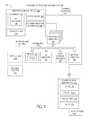
- FIG. 2selected elements of an embodiment of a system 200 with portable information handling system 100 and power storage adapter 172 are shown.
- FIG. 2illustrates further internal details of power storage adapter 172 . It is noted that FIG. 2 is not drawn to scale but is a schematic illustration. In various embodiments, power storage adapter 172 may be implemented using fewer or additional components than illustrated in FIG. 2 .
- power storage adapter 172is coupled to portable information handling system 100 via variable power bus (VPB) 142 , as described above with respect to FIG. 1 . Additionally, power storage adapter 172 is also externally connected to AC line power 146 , as described above with respect to FIG. 1 .
- VPBvariable power bus
- power storage adapter 172includes power sources 250 , a DC-DC converter 178 , a VPB controller 240 , and two ports 230 , as well as a PSA controller 221 comprising processor 220 and memory 224 .
- power sources 250comprise an AC-DC converter 176 , a PSA battery 174 , and a PSA BMU 170 - 2 .
- PSA BMU 170 - 2is shown including a charging unit 246 and a DC boost converter 248
- VPB controller 240is shown including a power distributor 242 and a data hub 244 .
- DC boost converter 248may include buck-boost DC conversion functionality to step up or step down an input DC voltage.
- VBP controller 240is depicted in FIG. 2 in an implementation with two ports 230 - 1 and 230 - 2 that support variable power bus 142 .
- variable power bus 142may be compatible with USB Type-C specifications promulgated by USB IF.
- port 230 - 1may be a USB Type-C port.
- port 230 - 1may also be a USB Type-C port or another type of port, such as a USB Type-A port, among others.
- two ports 230are shown in the example embodiment of FIG. 2 , it will be understood that power storage adapter 172 may include fewer or more ports 230 in different embodiments.
- power storage adapter 172includes PSA controller 221 , which may perform various actions and functions.
- PSA controller 221is implemented using a custom integrated circuit, or a customizable integrated circuit, such as a field programmable gate array (FPGA).
- PSA controller 221includes processor 220 and memory 224 , which may store executable instructions (such as executable code) that may be executed by processor 220 , which has access to memory 224 .
- Processor 220is typically implemented as an integrated circuit, such as a microprocessor or microcontroller, and is enabled to execute instructions that cause power storage adapter 172 to perform the functions and operations described herein.
- memory 224may include non-transitory computer-readable media that stores data and instructions for at least a period of time.
- Memory 224may comprise persistent and volatile media, fixed and removable media, and magnetic and semiconductor media.
- Memory 224may include, without limitation, storage media such as a direct access storage device (e.g., a hard disk drive or floppy disk), a sequential access storage device (e.g., a tape disk drive), compact disk (CD), random access memory (RAM), read-only memory (ROM), CD-ROM, digital versatile disc (DVD), electrically erasable programmable read-only memory (EEPROM) or flash memory, non-transitory media, or various combinations of the foregoing.
- Memory 224is operable to store instructions, data, or both.
- Memory 224may store sets or sequences of instructions that may represent executable computer programs for implementing various functionality provided by power storage adapter 172 .
- power storage adapter 172The functionality and implementation details of certain elements in power storage adapter 172 , such as AC-DC converter 176 , PSA battery 174 , PSA BMU 170 - 2 , and DC-DC converter 178 , are described above with respect to FIG. 1 .
- VPB controller 240may include power distributor 242 , which may represent various electronic components that enable distribution of DC power with respect to variable power bus 142 via ports 230 .
- power distributor 242may receive at least one DC power input from DC-DC converter 178 .
- Power distributor 242may route or switch power connections to respective ports 230 , for example, to enable fulfillment of a power contract, as described above.
- a power contract established by VPB controller 240such as according to a USB Power Delivery Specification, may govern the supply of DC power to portable information handling system 100 via port 230 - 1 .
- VPB controller 240may also establish another power contract to supply DC power to another device coupled to port 230 - 2 .
- VPB controller 240supplies DC power to both port 230 - 1 and port 230 - 2 .
- Power distributor 242may supply different DC voltages for output power at different ports 230 .
- power distributor 242supplies a different DC voltage to port 230 - 1 than to port 230 - 2 .
- data hub 244may represent electronic functionality to manage various VPB connections over variable power bus 142 .
- data hub 244may control operation of power distributor 242 and may, in turn, be controlled by PSA controller 221 , such as by executable code (not shown) stored in memory 224 and executed by processor 220 .
- data hub 244may store state information for each respective port 230 , such as USB state information.
- data hub 244may store information associated with power contracts that power storage adapter 172 has established or is in the process of negotiating. Accordingly, data hub 244 may store various information about different VPB devices connected to power storage adapter 172 via ports 230 .
- the phrase “power consuming device”may refer to any system, apparatus, or device consuming the electrical power provided by a battery.
- a portable information handling systemmay consume power for components such as one or more displays, processors, storage media, memory, or other components.
- charging unit 246 of BMU 170 - 2may draw electrical power from AC-DC converter 176 , and may, in turn output a charging voltage and charging current suitable to charge the cells of PSA battery 174 .
- the charging voltage and the charging current demands of the batterymay be dependent on an electrochemistry or a cell configuration of the battery cells.
- the charging of the batterymay be limited by the current supply capability of the DC source.
- the DC sourcemay be AC-DC converter 176 .
- BMU 170 - 2may stop drawing current from the AC-DC converter 176 .
- charging unit 246may also be enabled to supply electrical from PSA battery 174 , which is then boosted to a desired output voltage by DC boost converter 248 .
- portable information handling system 100may communicate with power storage adapter 172 to instruct PSA BMU 170 - 2 to charge the battery cells of PSA battery 174 .
- PSA BMU 170 - 2may send information to portable information handling system 100 , such as the cell configuration, the state of charge of the battery, or other information.
- Portable information handling system 100may communicate with PSA BMU 170 - 2 using a system management bus (not shown), for example System Management Bus (SMBus) promulgated by SBS Implementers Forum (www.smbus.org), in some embodiments.
- SMBSystem Management Bus
- PSA controller 221may determine that power storage adapter 172 may be connected to AC line power 146 source and drawing electrical power from that power source. PSA controller 221 may be connected to portable information handling system 100 , which may be supplying electrical power from AC line power 146 source to portable information handling system 100 .
- Portable information handling system 100may receive an indication of a peak shift specifying that portable information handling system 100 is to reduce electrical power consumption by ceasing to draw electrical power from an external AC line power source and switching to draw electrical power from internal battery 171 . After the peak shift begins, portable information handling system 100 will draw electrical power from internal battery 171 until the peak shift ends.
- power storage adapter 172may not receive the indication of the peak shift and may continue to draw electrical power from AC line power 146 source to power one or more of its internal components, e.g. an external display element such as a light emitting diode (LED) device included with power storage adapter 172 indicating whether the PSA is powered on.
- an external display elementsuch as a light emitting diode (LED) device included with power storage adapter 172 indicating whether the PSA is powered on.
- power storage adapter 172may continue to consume low levels of electrical power, e.g. 30 to 70 milliwatts, from AC line power 146 source, which would not reduce its electrical power consumption.
- PSA controller 221may receive an indication of a peak shift associated with AC line power 146 source, the indication specifying that power storage adapter 172 may cease drawing electrical power from AC line power 146 source.
- the indicationmay be a peak shift message from embedded controller 180 of portable information handling system 100 coupled to PSA port 230 - 1 of power storage adapter 172 .
- PSA controller 221may monitor a state of charge of PSA battery 174 .
- PSA controller 221may determine whether the monitored state of charge of PSA battery 174 is greater than a recharging state of charge. When the state of charge of PSA battery 174 is greater than a recharging state of charge, PSA battery 174 may be an available power source.
- PSA controller 221may electrically disconnect power storage adapter 174 from AC line power 146 source and begin supplying electrical power from PSA battery 174 to portable information handling system 100 coupled via PSA port 230 - 1 .
- FIG. 3illustrates a charging curve 300 for a battery, such as internal battery 171 or PSA battery 174 .
- Charging curve 300is schematically illustrated and is not drawn to scale or perspective.
- Charging curve 300may be implemented by BMU 170 , for example, using charging unit 246 (see FIG. 2 ).
- Charging curve 300depicts how a charging current 302 and a charging voltage 304 respond over time to various conditions. Specifically, at time 310 , it is assumed that the battery is discharged and is charged by supplying charging current 302 that is constant, given by Imax, which is a maximum charging current. In the constant current charging regime between time 310 and time 312 , charging voltage 304 may increase from a low value to a higher value as the SOC for the battery increases.
- charging voltage 304may approach a maximum value, given by Vmax, and may remain constant after time 312 .
- charging current 302may begin to decrease as the SOC for the battery increases at a lower rate.
- charging current 302may taper off until at some point, the SOC approaches a maximum value, and no further charging occurs.
- boost charging voltage 306may be applied to improve a charging efficiency, for example, by reducing an amount of electrical power consumed during charging, as compared with supplying constant charging voltage Vmax.
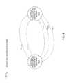
- Power supply adapter state machine 400describes states of power storage adapter 172 for performing a peak shift operation method, as described herein.
- the peak shift operation method described hereinmay be implemented with fewer or more elements than depicted in power supply adapter state machine 400 .
- states 402represent certain power states of power storage adapter 172 when connected to AC line power 146 and connected to portable information handling system 100 using PSA port 230 - 1 .
- PSA port 230 - 1may be a USB Type-C port.
- power storage adapter 172may establish a power delivery contract with portable information handling system 100 for a nominal amount of power, such as 30 Watts, in one example, as previously described with respect to FIG. 1 .
- embedded controller 180 of portable information handling system 100may also use a peak shift operation method to allow it to perform peak shift operations with power storage adapter 172 .
- embedded controller 180will not electrically disconnect power storage adapter 172 from portable information handling system 100 when it receives a peak shift network command from network interface 160 so it may still draw electrical power from power storage adapter 172 .
- PSA controller 221may determine whether power storage adapter 172 is connected to AC line power 146 .
- power storage adapter 172may begin supplying electrical power from AC line power 146 to portable information handling system 100 using PSA port 230 - 1 .
- power storage adapter 172may enter state 402 - 1 .
- PSA controller 221may receive an indication of a peak shift associated with AC line power 146 of power storage adapter 146 , the indication specifying that power storage adapter 172 may cease drawing electrical power from the AC line power source.
- the indicationmay be a peak shift message from embedded controller 180 of portable information handling system 100 coupled to PSA port 230 - 1 of power storage adapter 172 .
- the indicationmay be a peak shift message from an entity associated with AC line power 146 , and the peak shift message may be received using an Ethernet port coupled to PSA port 230 - 2 of power storage adapter 172 .
- power storage adapter 172may have already established a particular time of day, a particular duration of time, a particular repetition count and interval, that power storage 172 may enter peak shift operation from a previously received indication of a peak shift associated with AC line power 146 of power storage adapter 146 , which may allow power storage adapter 172 to enter peak shift operation directly without receiving other indications of a peak shift.
- PSA controller 221may monitor a state of charge of PSA battery 174 , which may be performed by BMU 170 , as previously described.
- PSA controller 221may determine whether the SOC of PSA battery 174 is greater than a recharging state of charge, which may be a SOC of about 90% for example. From state 402 - 2 , in response to the indication, the determination that the SOC of PSA battery 174 is greater than a recharging state of charge, and when the power storage adapter is electrically connected to the AC line power source, PSA controller 221 may electrically disconnect power storage adapter 172 from AC line power 174 , at action 404 - 1 , PSA controller 221 may begin supplying electrical power to portable information handling system 100 using PSA battery 174 and enter state 402 - 2 .
- a recharging state of chargewhich may be a SOC of about 90% for example. From state 402 - 2 , in response to the indication, the determination that the SOC of PSA battery 174 is greater than a recharging state of charge, and when the power storage adapter is electrically connected to the AC line power source, PSA controller 221 may
- PSA controller 221may electrically disconnect a DC output from AC/DC converter 176 to electrically disconnect power storage adapter 172 from AC line power 146 . In certain embodiments, PSA controller 221 may power off AC/DC converter 176 to electrically disconnect power storage adapter 172 from AC line power 146 .
- PSA controller 221may receive a second indication of termination of the peak shift. From state 402 - 2 , PSA controller 221 may determine whether power storage adapter 172 is connected to AC line power 146 . In response to the second indication and the determination that power storage adapter 172 is connected to AC line power 146 , PSA controller 221 may electrically connect power storage adapter 172 to AC line power 146 , at action 406 - 1 , PSA controller 221 may begin supplying electrical power to portable information handling system 100 using AC line power 146 and re-enter state 402 - 1 . By entering state 402 - 1 from state 402 - 2 , the peak shift operation to terminate the peak shift has been completed. In one or more embodiments, the second indication may be received by PSA controller 221 from embedded controller 180 of portable information handling system 100 coupled to PSA port 230 - 1 .
- the indicationmay further specify a duration of time of the peak shift.
- the indicationmay indicate that power storage adapter 172 is to go into peak shift mode for the next four hours during a time of day where there is high power demand.
- PSA controller 221may, in response to determining that the duration of time of the peak shift has been reached and that power storage adapter 172 is connected to AC line power 146 , PSA controller 221 may electrically connect power storage adapter 172 to AC line power 146 , at action 406 - 2 , PSA controller 221 may begin supplying electrical power to portable information handling system 100 using AC line power 146 and re-enter state 402 - 1 .
- PSA controller 221may monitor the SOC of PSA battery 174 . From state 402 - 2 , PSA controller 221 may determine whether the SOC of PSA battery 174 is less than or equal to the recharging state of charge.
- PSA controller 221may, in response to determining that the state of charge is less than or equal to the recharging state of charge and that power storage adapter 172 is connected to AC line power 146 , electrically connect power storage adapter 172 to AC line power 146 , at action 406 - 3 , PSA controller 221 may begin recharging PSA battery 174 from AC line power 146 and re-enter state 402 - 1 .
- PSA controller 221may monitor the SOC of PSA battery 174 . From state 402 - 1 , PSA controller 221 may determine whether the SOC of PSA battery 174 is greater than the recharging state of charge.
- PSA controller 221may, in response to determining that the state of charge is greater than the recharging state of charge, that PSA controller 221 has received the indication of the peak shift, that PSA controller 221 has not received a second indication of termination of the peak shift, and when the power storage adapter is electrically connected to the AC line power source, electrically disconnect power storage adapter 172 from AC line power 174 , at action 404 - 2 , PSA controller 221 may begin supplying electrical power to portable information handling system 100 using PSA battery 174 and re-enter state 402 - 2 .
- PSA controller 221 of power storage adapter 172 and embedded controller 180 of portable information handling system 100may utilize a common protocol layer for communication between each other, where the common protocol layer may be a universal serial bus (USB) power delivery protocol layer.
- USBuniversal serial bus
- Method 500may be performed using power storage adapter 172 (see FIGS. 1, and 2 ), in conjunction with portable information handling system 100 and, in particular, by PSA controller 221 .
- Method 500may be performed when supplying electrical power from AC line power 146 to portable information handling system 100 via PSA port 230 - 1 and PSA controller 221 receives an indication of a peak shift associated with AC line power 146 . It is noted that certain operations described in method 500 may be optional or may be rearranged in different embodiments.
- Method 500may begin at step 502 by receiving, by PSA controller 221 of power storage adapter 172 , an indication of a peak shift associated with AC line power 146 of power storage adapter 172 , the indication specifying that power storage adapter 172 may cease drawing electrical power from AC line power 146 .
- the indication in step 502may be a peak shift message from embedded controller 180 of portable information handling system 100 coupled to PSA port 230 - 1 of power storage adapter 172 .
- determining, by PSA controller 221determining, by PSA controller 221 , that a state of charge (SOC) of PSA battery 174 of power storage adapter 172 may be greater than a recharging state of charge.
- SOCstate of charge
- the determination of the SOC of PSA battery 174 in step 504may be performed by BMU 170 , as previously described.
- step 506in response to the indication and when power storage adapter 172 is electrically connected to AC line power 146 , electrically disconnecting, by PSA controller 221 , power storage adapter 172 from AC line power 146 . Electrically disconnecting power storage adapter 172 from AC line power 146 in step 508 may be accomplished by one of the various methods performed by PSA controller 221 , described above.
- a power storage adaptermay use a peak shift operation method when supplying electrical power from an AC line power source to a portable information handling system and the power storage adapter receives an indication of a peak shift associated with the AC line power source.
- the power storage adaptermay cease drawing power from the AC line power source and begin supplying electrical power from a battery included with the power storage adapter to the portable information handling system.
Landscapes
- Engineering & Computer Science (AREA)
- Power Engineering (AREA)
- Charge And Discharge Circuits For Batteries Or The Like (AREA)
Abstract
Description
| TABLE 1 |
| USB Power Delivery revision 2.0, version 1.2 source power rules. |
| Source Output | Current [A] at | Current [A] at | Current [A] at | Current [A] at |
| Power [W] | +5 V DC | +9 V DC | +15 V DC | +20 V DC |
| 0.5 to 15 | 0.1 to 3.0 | none | none | none |
| 15 to 27 | 3.0 (15 W limit) | 1.7 to 3.0 | none | none |
| 27 to 45 | 3.0 (15 W limit) | 3.0 (27 W limit) | 1.8 to 3.0 | none |
| 45 to 60 | 3.0 (15 W limit) | 3.0 (27 W limit) | 3.0 (45 W limit) | 2.25 to 3.0 |
| 60 to 100 | 3.0 (15 W limit) | 3.0 (27 W limit) | 3.0 (45 W limit) | 3.0 to 5.0 |
As shown in Table 1, USB Power Delivery defines four standardized voltage levels (+5V DC, +9V DC, +15V DC, and +20V DC), while power supplies may provide electrical power from 0.5 W to 100 W.
Claims (20)
Priority Applications (1)
| Application Number | Priority Date | Filing Date | Title |
|---|---|---|---|
| US15/631,786US10476288B2 (en) | 2017-06-23 | 2017-06-23 | Power storage adapter for peak shift operation with a portable information handling system |
Applications Claiming Priority (1)
| Application Number | Priority Date | Filing Date | Title |
|---|---|---|---|
| US15/631,786US10476288B2 (en) | 2017-06-23 | 2017-06-23 | Power storage adapter for peak shift operation with a portable information handling system |
Publications (2)
| Publication Number | Publication Date |
|---|---|
| US20180375360A1 US20180375360A1 (en) | 2018-12-27 |
| US10476288B2true US10476288B2 (en) | 2019-11-12 |
Family
ID=64693708
Family Applications (1)
| Application Number | Title | Priority Date | Filing Date |
|---|---|---|---|
| US15/631,786ActiveUS10476288B2 (en) | 2017-06-23 | 2017-06-23 | Power storage adapter for peak shift operation with a portable information handling system |
Country Status (1)
| Country | Link |
|---|---|
| US (1) | US10476288B2 (en) |
Cited By (5)
| Publication number | Priority date | Publication date | Assignee | Title |
|---|---|---|---|---|
| US20200241614A1 (en)* | 2019-01-25 | 2020-07-30 | Dell Products, L.P. | Indicator for ac power adapter |
| US11314311B2 (en)* | 2019-09-20 | 2022-04-26 | Dell Products, L.P. | Battery runtime and performance management based upon presence detection |
| US20220155846A1 (en)* | 2019-07-31 | 2022-05-19 | Hewlett-Packard Development Company, L.P. | Power source devices for power delivery contract selections |
| US20220302729A1 (en)* | 2019-11-08 | 2022-09-22 | Hewlett-Packard Development Company, L.P. | Charge determination |
| US11876439B2 (en) | 2021-01-14 | 2024-01-16 | Apple Inc. | Mitigation of battery output voltage ripple under pulse load |
Families Citing this family (15)
| Publication number | Priority date | Publication date | Assignee | Title |
|---|---|---|---|---|
| US10452102B2 (en) | 2017-06-23 | 2019-10-22 | Dell Products L.P. | Power delivery contract establishment in a power storage adapter |
| US10928880B2 (en) | 2017-06-23 | 2021-02-23 | Dell Products L.P. | Power storage adapter for communicating battery data with a portable information handling system |
| US10476288B2 (en) | 2017-06-23 | 2019-11-12 | Dell Products L.P. | Power storage adapter for peak shift operation with a portable information handling system |
| US10389154B2 (en) | 2017-06-23 | 2019-08-20 | Dell Products L.P. | Power storage adapter using a high efficiency charging method |
| US10978896B2 (en) | 2017-06-23 | 2021-04-13 | Dell Products L.P. | High efficiency power storage adapter |
| US10381844B2 (en) | 2017-06-23 | 2019-08-13 | Dell Products L.P. | Sourcing power from a battery or AC-DC converter of a power storage adapter |
| US10608443B2 (en) | 2017-08-15 | 2020-03-31 | Dell Products L.P. | Battery management using battery temperature distribution |
| US10642333B2 (en) | 2017-08-24 | 2020-05-05 | Dell Products L.P. | Power storage adapter for efficient supply of power of multiple portable information handling systems |
| US10620679B2 (en) | 2017-09-01 | 2020-04-14 | Dell Products L.P. | Prioritizing supplying electrical power by a power storage adapter to connected devices |
| US10673271B2 (en) | 2017-09-01 | 2020-06-02 | Dell Products L.P. | Efficient charging of multiple portable information handling systems based on learned charging characteristics |
| US10404105B2 (en) | 2017-09-14 | 2019-09-03 | Dell Products L.P. | Power storage adapter for wireless power transmission |
| US10714797B2 (en) | 2017-09-18 | 2020-07-14 | Dell Products L.P. | Multilayer thermal laminate with aerogel for battery cell enclosures |
| US11513928B2 (en)* | 2017-09-18 | 2022-11-29 | Dell Products L.P. | Power storage adapter with power cable validation |
| US10488906B2 (en) | 2017-09-26 | 2019-11-26 | Dell Products L.P. | Power delivery based on temperature and other factors in a power storage adapter |
| WO2022085924A1 (en)* | 2020-10-19 | 2022-04-28 | 주식회사 브로나인 | Power supply device, method, and program based on power specification analysis of connected electronic device |
Citations (100)
| Publication number | Priority date | Publication date | Assignee | Title |
|---|---|---|---|---|
| US1012876A (en) | 1909-11-29 | 1911-12-26 | George Henry Maas | Seal-lock. |
| US1018173A (en) | 1909-06-21 | 1912-02-20 | Anderson Tool Company | Scale. |
| US4672228A (en) | 1985-09-03 | 1987-06-09 | Pioneer Magnetics, Inc. | Battery backup system for switched power supply |
| US5598327A (en) | 1990-11-30 | 1997-01-28 | Burr-Brown Corporation | Planar transformer assembly including non-overlapping primary and secondary windings surrounding a common magnetic flux path area |
| US5811895A (en) | 1994-08-12 | 1998-09-22 | International Business Machines Corp. | Power supply circuit for use with a battery and an AC power adaptor |
| US6057609A (en) | 1997-05-07 | 2000-05-02 | Sony Corporation | Auxiliary power supply apparatus |
| US6293700B1 (en) | 1999-09-24 | 2001-09-25 | Fluke Corporation | Calibrated isothermal assembly for a thermocouple thermometer |
| US6477054B1 (en) | 2000-08-10 | 2002-11-05 | Tektronix, Inc. | Low temperature co-fired ceramic substrate structure having a capacitor and thermally conductive via |
| US20030085626A1 (en)* | 2001-10-29 | 2003-05-08 | International Business Machines Corporation | Electrical apparatus, computer, power switching unit, and power switching method |
| US20030212923A1 (en) | 2002-05-08 | 2003-11-13 | Dell Products L.P. | Method of thermal shut down and failure status capture in a storage enclosure |
| US20040075418A1 (en) | 2000-09-21 | 2004-04-22 | Densham William L. | Power management for battery powered appliances |
| US20040125618A1 (en) | 2002-12-26 | 2004-07-01 | Michael De Rooij | Multiple energy-source power converter system |
| US20040135565A1 (en) | 2002-10-10 | 2004-07-15 | Douma Darin J. | Microprocessor controlled boost converter |
| US20050052164A1 (en) | 2003-09-09 | 2005-03-10 | Setsuo Sakai | Power supply device |
| US20050125709A1 (en) | 2003-12-05 | 2005-06-09 | Mckim James B.Jr. | Communications system for implementation of synchronous, multichannel, galvanically isolated instrumentation devices |
| US20050131645A1 (en) | 2003-06-09 | 2005-06-16 | Panopoulos Peter J. | Machine having automatic transport with scanning and GPS functions |
| US20050174094A1 (en) | 2004-02-11 | 2005-08-11 | Research In Motion Limited, A Canadian Corporation | Battery charger for portable devices and related methods |
| US20050275383A1 (en) | 2004-06-15 | 2005-12-15 | Toyota Jidosha Kabushiki Kaisha | Method for detecting abnormality of temperature sensors, and power supply apparatus |
| US20060022637A1 (en) | 2004-07-29 | 2006-02-02 | Dell Products L.P. | Method for detecting a defective charger circuit |
| US20060164038A1 (en) | 2005-01-25 | 2006-07-27 | Remi Demers | Power supply charging method and device |
| US7127228B2 (en) | 2001-12-07 | 2006-10-24 | Acer Communications And Multimedia Inc. | Portable electric device with power failure recovery and operation method thereof |
| US20070079153A1 (en) | 2005-10-05 | 2007-04-05 | Dell Products L.P. | Information handling system, current and voltage mode power adapter, and method of operation |
| US20070103110A1 (en) | 2005-10-24 | 2007-05-10 | Samsung Electronics Co., Ltd. | Apparatus and method of wirelessly sharing power by inductive method |
| US7243246B2 (en) | 2003-12-19 | 2007-07-10 | Dell Products L.P. | System having a power adapter that generates a data signal based on the state of a external power source that is used to manage the power consumption of a CPU |
| US20070200433A1 (en)* | 2006-02-14 | 2007-08-30 | Matsushita Battery Industrial | Consumer-sited power management system and method |
| US20070248877A1 (en) | 2006-03-31 | 2007-10-25 | Qahoug Jaber A | Gradient non-linear adaptive power architecture and scheme |
| US20070279004A1 (en) | 2006-05-19 | 2007-12-06 | Dell Products L.P. | Portable charging system |
| US20080222431A1 (en) | 2006-08-30 | 2008-09-11 | Frank Paniagua | Power Adapter Capable of Communicating Digitally with Electronic Devices |
| US20080315826A1 (en) | 2007-06-20 | 2008-12-25 | Motorola, Inc. | Devices, systems, and methods for group charging of electronic devices |
| US20090001937A1 (en) | 2007-03-07 | 2009-01-01 | O2Micro, Inc. | Power management systems with controllable adapter output |
| US20090076661A1 (en) | 2007-07-25 | 2009-03-19 | Ken Pearson | Apparatus, system, and method to manage the generation and use of hybrid electric power |
| US7536569B2 (en) | 2006-04-24 | 2009-05-19 | Dell Products L.P. | System and method for managing power provided to a portable information handling system |
| US7545120B2 (en) | 2003-07-29 | 2009-06-09 | Dell Products L.P. | AC-DC adapter and battery charger integration for portable information handling systems |
| US20090146826A1 (en) | 2007-12-10 | 2009-06-11 | Igor Gofman | Rapid Charging And Power Management Of A Battery-Powered Fluid Analyte Meter |
| US20090177906A1 (en) | 2006-08-30 | 2009-07-09 | Paniagua Jr Frank | Powering An Electrical Device Through a Legacy Adapter Capable of Digital Communication |
| US7592716B2 (en) | 2003-07-29 | 2009-09-22 | Dell Products L.P. | Information handling system including a battery that reduces a voltage fluctuation |
| US20090244944A1 (en) | 2008-03-25 | 2009-10-01 | Delta Electronics, Inc. | Power converter system that operates efficiently over a range of load conditions |
| US20100038963A1 (en) | 2008-08-13 | 2010-02-18 | Dell Products L.P. | Systems and Methods for Power Supply Wear Leveling In a Blade Server Chassis |
| US20100067197A1 (en) | 2008-09-12 | 2010-03-18 | Callpod Inc. | Portable multi-device power supply, battery charger, and docking system |
| US20110068626A1 (en) | 2009-09-24 | 2011-03-24 | Terlizzi Jeffrey J | Multiport power converter with load detection capabilities |
| US7989981B2 (en) | 2006-02-02 | 2011-08-02 | Flextronics Ap, Llc | Power adaptor and storage unit for portable devices |
| US20110225073A1 (en) | 2010-03-12 | 2011-09-15 | Samsung Electronics Co., Ltd. | Apparatus and method for performing wireless charging |
| US20110227407A1 (en) | 2010-03-16 | 2011-09-22 | Gm Global Technology Operations, Inc. | Systems and methods for deactivating a matrix converter |
| US20110260681A1 (en) | 2010-04-27 | 2011-10-27 | Guccione Darren S | Portable Wireless Charging Device |
| US20120025630A1 (en) | 2010-07-28 | 2012-02-02 | Toshiba Tec Kabushiki Kaisha | Image forming apparatus |
| US20120084575A1 (en) | 2010-09-30 | 2012-04-05 | Jose Luis Flores | Synchronized Voltage Scaling and Device Calibration |
| US20120091815A1 (en) | 2010-10-15 | 2012-04-19 | Dell Products L.P. | System and Method for Thermal Protection in a Power System |
| US8164904B2 (en) | 2006-04-19 | 2012-04-24 | Osram Ag | Electronic component module |
| US20120123604A1 (en)* | 2010-11-12 | 2012-05-17 | Nathan Bowman Littrell | Systems, methods, and apparatus for demand response of battery-powered devices |
| US8188594B2 (en) | 2008-09-29 | 2012-05-29 | Intel Corporation | Input/output package architectures |
| US20120151240A1 (en) | 2009-07-10 | 2012-06-14 | Protonex Technology Corporation | Portable power manager |
| US20120181990A1 (en) | 2011-01-19 | 2012-07-19 | Denso Corporation | Dc power supply apparatus |
| US20120201062A1 (en) | 2009-10-29 | 2012-08-09 | Seoby Electronics Co., Ltd. | Standby power cut-off device and control method thereof and power supply |
| US20120256484A1 (en) | 2011-04-11 | 2012-10-11 | James Kemp | Computer adapter with power outlet and replaceable and rechargeable battery, wireless card, and transceiver |
| US20120316695A1 (en)* | 2011-06-07 | 2012-12-13 | Fujitsu Limited | System and Method for Managing Power Consumption |
| US20120319656A1 (en)* | 2011-06-14 | 2012-12-20 | Hideyuki Toma | Power control apparatus and power control method |
| US20130043827A1 (en) | 2011-08-10 | 2013-02-21 | Nathan Daniel Weinstein | Portable power charger |
| US20130100568A1 (en) | 2011-10-20 | 2013-04-25 | Pradeep Mistry | Information Handling System Power Supply Automated De-Rating For Power Output And Thermal Constraints |
| US20130159792A1 (en) | 2011-01-24 | 2013-06-20 | Robert Brooks | Fault detection |
| US20130314039A1 (en) | 2011-02-02 | 2013-11-28 | Bayerische Motoren Werke Aktiengesellschaft | Charging Device for an Electric Energy Storage Device in a Motor Vehicle |
| US20140018969A1 (en)* | 2012-07-14 | 2014-01-16 | Joseph W. Forbes, Jr. | Method and Apparatus for Actively Managing Electric Power Supply for an Electric Power Grid |
| US20140035380A1 (en) | 2012-08-02 | 2014-02-06 | Sandisk Technologies Inc. | Wireless power transfer |
| US20140157065A1 (en) | 2012-02-11 | 2014-06-05 | Adrian E. Ong | Method and system for providing a smart memory architecture |
| US20140210267A1 (en)* | 2011-09-16 | 2014-07-31 | Hitachi, Ltd. | Power distribution device |
| US20140214223A1 (en)* | 2011-08-30 | 2014-07-31 | Hitachi, Ltd. | System Stabilization System |
| US20140217958A1 (en) | 2013-02-05 | 2014-08-07 | Dell Products L.P. | Mitigating premature wear out of a rechargeable battery |
| US20140239882A1 (en) | 2013-02-26 | 2014-08-28 | System General Corporation | Apparatus for charging battery through programmable power adapter |
| US20150063473A1 (en)* | 2013-08-30 | 2015-03-05 | Kabushiki Kaisha Toshiba | Power electronics device, cooperative control method and non-transitory computer readable medium |
| US20150132615A1 (en) | 2013-11-13 | 2015-05-14 | Samsung Sdi Co., Ltd. | Battery pack, apparatus including battery pack, and method of managing battery pack |
| US20150165917A1 (en) | 2011-12-29 | 2015-06-18 | Abb B.V. | Method, system and charger for charging a battery of an electric vehicle |
| US9166083B2 (en) | 2010-09-09 | 2015-10-20 | Texas Instruments Incorporated | Reducing thermal gradients to improve thermopile performance |
| US9197092B2 (en) | 2012-10-30 | 2015-11-24 | Dell Products L.P. | Battery charge management using usage profiling |
| US20150364921A1 (en) | 2014-06-17 | 2015-12-17 | Samsung Sdi Co., Ltd. | Power assist unit and power assist system |
| US9300015B2 (en) | 2010-05-04 | 2016-03-29 | Dell Products Lp | Systems and methods for monitoring and characterizing information handling system use behavior |
| US20160099608A1 (en) | 2014-10-01 | 2016-04-07 | Jatbok Technology Co., Ltd. | Power adapter with built-in battery and power storage and supply method thereof |
| US20160241148A1 (en) | 2015-02-13 | 2016-08-18 | Avogy, Inc. | Method and system for integrated power supply with accessory functions |
| US20160246316A1 (en) | 2015-02-24 | 2016-08-25 | Intersil Americas LLC | System and method for determining adapter current limit |
| US20160274607A1 (en) | 2013-02-08 | 2016-09-22 | Nec Corporation | Battery control device, battery control support device, battery control system, battery control method, battery control support method, and recording medium |
| US20160329612A1 (en) | 2014-12-19 | 2016-11-10 | Lg Chem, Ltd. | Apparatus and method for controlling power for secondary battery |
| US20160359426A1 (en) | 2013-12-11 | 2016-12-08 | Rompower Energy Systems, Inc. | Packaging method for very high density converters |
| US9524018B2 (en) | 2013-08-30 | 2016-12-20 | Dell Products, Lp | Adaptive integral battery pack and voltage regulator |
| US20170040815A1 (en) | 2015-08-07 | 2017-02-09 | Paypal, Inc. | Smart charging of user devices |
| US9568990B2 (en) | 2008-10-16 | 2017-02-14 | Dell Products L.P. | System and method for managing power consumption of an information handling system |
| US20170085098A1 (en) | 2015-09-17 | 2017-03-23 | Qualcomm Incorporated | Systems and methods for charging a battery |
| US20170104330A1 (en)* | 2014-05-19 | 2017-04-13 | Nec Corporation | Control device, control method, and program |
| US9681558B2 (en) | 2014-08-12 | 2017-06-13 | Infineon Technologies Ag | Module with integrated power electronic circuitry and logic circuitry |
| US20170177069A1 (en) | 2015-12-21 | 2017-06-22 | Intel Corporation | Smart power adapters and related systems and methods |
| US9693446B2 (en) | 2013-12-13 | 2017-06-27 | Endress+Hauser Conducta Gmbh+Co. Kg | Circuit board with thermal control |
| US20170225586A1 (en) | 2016-02-04 | 2017-08-10 | Johnson Controls Technology Company | Battery system temperature and charge adjustment system and method |
| US9812878B1 (en) | 2015-06-19 | 2017-11-07 | Amazon Technologies, Inc. | Dynamic current redistribution for portable electronic devices |
| US9867275B2 (en) | 2015-07-27 | 2018-01-09 | Delta Electronics (Shanghai) Co., Ltd. | Modular power supply and method for manufacturing the same |
| US9887571B1 (en) | 2017-06-23 | 2018-02-06 | Dell Products L.P. | Combining power from an internal battery and an external power storage adapter |
| US20180181171A1 (en) | 2016-12-23 | 2018-06-28 | Samsung Electronics Co., Ltd. | Electronic device and heat control method based on temperature of battery in electronic device |
| US20180233914A1 (en)* | 2015-08-07 | 2018-08-16 | Sharp Kabushiki Kaisha | Control device, energy management device, system, and control method |
| US20180351399A1 (en) | 2017-05-30 | 2018-12-06 | Schneider Electric It Corporation | System and method for power storage and distribution |
| US20180375361A1 (en) | 2017-06-23 | 2018-12-27 | Dell Products L.P. | Low standby power in a power storage adapter enabled by an associated battery |
| US20180375359A1 (en) | 2017-06-23 | 2018-12-27 | Dell Products L.P. | Power storage adapter using a high efficiency charging method |
| US20180375360A1 (en) | 2017-06-23 | 2018-12-27 | Dell Products L.P. | Power storage adapter for peak shift operation with a portable information handling system |
| US20180375358A1 (en) | 2017-06-23 | 2018-12-27 | Dell Products L.P. | High efficiency power storage adapter |
| US20190050037A1 (en) | 2017-08-11 | 2019-02-14 | Norel Systems Limited | Intelligent mobile power supply and method for usb data communication therewith |
- 2017
- 2017-06-23USUS15/631,786patent/US10476288B2/enactiveActive
Patent Citations (103)
| Publication number | Priority date | Publication date | Assignee | Title |
|---|---|---|---|---|
| US1018173A (en) | 1909-06-21 | 1912-02-20 | Anderson Tool Company | Scale. |
| US1012876A (en) | 1909-11-29 | 1911-12-26 | George Henry Maas | Seal-lock. |
| US4672228A (en) | 1985-09-03 | 1987-06-09 | Pioneer Magnetics, Inc. | Battery backup system for switched power supply |
| US5598327A (en) | 1990-11-30 | 1997-01-28 | Burr-Brown Corporation | Planar transformer assembly including non-overlapping primary and secondary windings surrounding a common magnetic flux path area |
| US5811895A (en) | 1994-08-12 | 1998-09-22 | International Business Machines Corp. | Power supply circuit for use with a battery and an AC power adaptor |
| US6057609A (en) | 1997-05-07 | 2000-05-02 | Sony Corporation | Auxiliary power supply apparatus |
| US6293700B1 (en) | 1999-09-24 | 2001-09-25 | Fluke Corporation | Calibrated isothermal assembly for a thermocouple thermometer |
| US6477054B1 (en) | 2000-08-10 | 2002-11-05 | Tektronix, Inc. | Low temperature co-fired ceramic substrate structure having a capacitor and thermally conductive via |
| US20040075418A1 (en) | 2000-09-21 | 2004-04-22 | Densham William L. | Power management for battery powered appliances |
| US20030085626A1 (en)* | 2001-10-29 | 2003-05-08 | International Business Machines Corporation | Electrical apparatus, computer, power switching unit, and power switching method |
| US7127228B2 (en) | 2001-12-07 | 2006-10-24 | Acer Communications And Multimedia Inc. | Portable electric device with power failure recovery and operation method thereof |
| US20030212923A1 (en) | 2002-05-08 | 2003-11-13 | Dell Products L.P. | Method of thermal shut down and failure status capture in a storage enclosure |
| US20040135565A1 (en) | 2002-10-10 | 2004-07-15 | Douma Darin J. | Microprocessor controlled boost converter |
| US20040125618A1 (en) | 2002-12-26 | 2004-07-01 | Michael De Rooij | Multiple energy-source power converter system |
| US20050131645A1 (en) | 2003-06-09 | 2005-06-16 | Panopoulos Peter J. | Machine having automatic transport with scanning and GPS functions |
| US7545120B2 (en) | 2003-07-29 | 2009-06-09 | Dell Products L.P. | AC-DC adapter and battery charger integration for portable information handling systems |
| US7592716B2 (en) | 2003-07-29 | 2009-09-22 | Dell Products L.P. | Information handling system including a battery that reduces a voltage fluctuation |
| US20050052164A1 (en) | 2003-09-09 | 2005-03-10 | Setsuo Sakai | Power supply device |
| US20050125709A1 (en) | 2003-12-05 | 2005-06-09 | Mckim James B.Jr. | Communications system for implementation of synchronous, multichannel, galvanically isolated instrumentation devices |
| US7243246B2 (en) | 2003-12-19 | 2007-07-10 | Dell Products L.P. | System having a power adapter that generates a data signal based on the state of a external power source that is used to manage the power consumption of a CPU |
| US20050174094A1 (en) | 2004-02-11 | 2005-08-11 | Research In Motion Limited, A Canadian Corporation | Battery charger for portable devices and related methods |
| US20050275383A1 (en) | 2004-06-15 | 2005-12-15 | Toyota Jidosha Kabushiki Kaisha | Method for detecting abnormality of temperature sensors, and power supply apparatus |
| US20060022637A1 (en) | 2004-07-29 | 2006-02-02 | Dell Products L.P. | Method for detecting a defective charger circuit |
| US7538518B2 (en) | 2004-07-29 | 2009-05-26 | Dell Products L.P. | Method for detecting a defective charger circuit |
| US20060164038A1 (en) | 2005-01-25 | 2006-07-27 | Remi Demers | Power supply charging method and device |
| US20070079153A1 (en) | 2005-10-05 | 2007-04-05 | Dell Products L.P. | Information handling system, current and voltage mode power adapter, and method of operation |
| US20070103110A1 (en) | 2005-10-24 | 2007-05-10 | Samsung Electronics Co., Ltd. | Apparatus and method of wirelessly sharing power by inductive method |
| US7989981B2 (en) | 2006-02-02 | 2011-08-02 | Flextronics Ap, Llc | Power adaptor and storage unit for portable devices |
| US20070200433A1 (en)* | 2006-02-14 | 2007-08-30 | Matsushita Battery Industrial | Consumer-sited power management system and method |
| US20070248877A1 (en) | 2006-03-31 | 2007-10-25 | Qahoug Jaber A | Gradient non-linear adaptive power architecture and scheme |
| US8164904B2 (en) | 2006-04-19 | 2012-04-24 | Osram Ag | Electronic component module |
| US7536569B2 (en) | 2006-04-24 | 2009-05-19 | Dell Products L.P. | System and method for managing power provided to a portable information handling system |
| US20070279004A1 (en) | 2006-05-19 | 2007-12-06 | Dell Products L.P. | Portable charging system |
| US20080222431A1 (en) | 2006-08-30 | 2008-09-11 | Frank Paniagua | Power Adapter Capable of Communicating Digitally with Electronic Devices |
| US20090177906A1 (en) | 2006-08-30 | 2009-07-09 | Paniagua Jr Frank | Powering An Electrical Device Through a Legacy Adapter Capable of Digital Communication |
| US20090001937A1 (en) | 2007-03-07 | 2009-01-01 | O2Micro, Inc. | Power management systems with controllable adapter output |
| US20080315826A1 (en) | 2007-06-20 | 2008-12-25 | Motorola, Inc. | Devices, systems, and methods for group charging of electronic devices |
| US20090076661A1 (en) | 2007-07-25 | 2009-03-19 | Ken Pearson | Apparatus, system, and method to manage the generation and use of hybrid electric power |
| US20090146826A1 (en) | 2007-12-10 | 2009-06-11 | Igor Gofman | Rapid Charging And Power Management Of A Battery-Powered Fluid Analyte Meter |
| US20090244944A1 (en) | 2008-03-25 | 2009-10-01 | Delta Electronics, Inc. | Power converter system that operates efficiently over a range of load conditions |
| US20100038963A1 (en) | 2008-08-13 | 2010-02-18 | Dell Products L.P. | Systems and Methods for Power Supply Wear Leveling In a Blade Server Chassis |
| US20100067197A1 (en) | 2008-09-12 | 2010-03-18 | Callpod Inc. | Portable multi-device power supply, battery charger, and docking system |
| US8188594B2 (en) | 2008-09-29 | 2012-05-29 | Intel Corporation | Input/output package architectures |
| US9568990B2 (en) | 2008-10-16 | 2017-02-14 | Dell Products L.P. | System and method for managing power consumption of an information handling system |
| US20120151240A1 (en) | 2009-07-10 | 2012-06-14 | Protonex Technology Corporation | Portable power manager |
| US20130342011A1 (en) | 2009-07-10 | 2013-12-26 | Protonex Technology Corporation | Power managers and methods for operating power managers |
| US20110068626A1 (en) | 2009-09-24 | 2011-03-24 | Terlizzi Jeffrey J | Multiport power converter with load detection capabilities |
| US20120201062A1 (en) | 2009-10-29 | 2012-08-09 | Seoby Electronics Co., Ltd. | Standby power cut-off device and control method thereof and power supply |
| US20110225073A1 (en) | 2010-03-12 | 2011-09-15 | Samsung Electronics Co., Ltd. | Apparatus and method for performing wireless charging |
| US20110227407A1 (en) | 2010-03-16 | 2011-09-22 | Gm Global Technology Operations, Inc. | Systems and methods for deactivating a matrix converter |
| US20110260681A1 (en) | 2010-04-27 | 2011-10-27 | Guccione Darren S | Portable Wireless Charging Device |
| US9300015B2 (en) | 2010-05-04 | 2016-03-29 | Dell Products Lp | Systems and methods for monitoring and characterizing information handling system use behavior |
| US20120025630A1 (en) | 2010-07-28 | 2012-02-02 | Toshiba Tec Kabushiki Kaisha | Image forming apparatus |
| US9166083B2 (en) | 2010-09-09 | 2015-10-20 | Texas Instruments Incorporated | Reducing thermal gradients to improve thermopile performance |
| US20120084575A1 (en) | 2010-09-30 | 2012-04-05 | Jose Luis Flores | Synchronized Voltage Scaling and Device Calibration |
| US20120091815A1 (en) | 2010-10-15 | 2012-04-19 | Dell Products L.P. | System and Method for Thermal Protection in a Power System |
| US20120123604A1 (en)* | 2010-11-12 | 2012-05-17 | Nathan Bowman Littrell | Systems, methods, and apparatus for demand response of battery-powered devices |
| US20120181990A1 (en) | 2011-01-19 | 2012-07-19 | Denso Corporation | Dc power supply apparatus |
| US20130159792A1 (en) | 2011-01-24 | 2013-06-20 | Robert Brooks | Fault detection |
| US20130314039A1 (en) | 2011-02-02 | 2013-11-28 | Bayerische Motoren Werke Aktiengesellschaft | Charging Device for an Electric Energy Storage Device in a Motor Vehicle |
| US20120256484A1 (en) | 2011-04-11 | 2012-10-11 | James Kemp | Computer adapter with power outlet and replaceable and rechargeable battery, wireless card, and transceiver |
| US20120316695A1 (en)* | 2011-06-07 | 2012-12-13 | Fujitsu Limited | System and Method for Managing Power Consumption |
| US20120319656A1 (en)* | 2011-06-14 | 2012-12-20 | Hideyuki Toma | Power control apparatus and power control method |
| US20130043827A1 (en) | 2011-08-10 | 2013-02-21 | Nathan Daniel Weinstein | Portable power charger |
| US20140214223A1 (en)* | 2011-08-30 | 2014-07-31 | Hitachi, Ltd. | System Stabilization System |
| US20140210267A1 (en)* | 2011-09-16 | 2014-07-31 | Hitachi, Ltd. | Power distribution device |
| US20130100568A1 (en) | 2011-10-20 | 2013-04-25 | Pradeep Mistry | Information Handling System Power Supply Automated De-Rating For Power Output And Thermal Constraints |
| US20150165917A1 (en) | 2011-12-29 | 2015-06-18 | Abb B.V. | Method, system and charger for charging a battery of an electric vehicle |
| US20140157065A1 (en) | 2012-02-11 | 2014-06-05 | Adrian E. Ong | Method and system for providing a smart memory architecture |
| US20140018969A1 (en)* | 2012-07-14 | 2014-01-16 | Joseph W. Forbes, Jr. | Method and Apparatus for Actively Managing Electric Power Supply for an Electric Power Grid |
| US20140035380A1 (en) | 2012-08-02 | 2014-02-06 | Sandisk Technologies Inc. | Wireless power transfer |
| US9197092B2 (en) | 2012-10-30 | 2015-11-24 | Dell Products L.P. | Battery charge management using usage profiling |
| US9263912B2 (en) | 2013-02-05 | 2016-02-16 | Dell Products, L.P. | Mitigating premature wear out of a rechargeable battery |
| US20140217958A1 (en) | 2013-02-05 | 2014-08-07 | Dell Products L.P. | Mitigating premature wear out of a rechargeable battery |
| US20160274607A1 (en) | 2013-02-08 | 2016-09-22 | Nec Corporation | Battery control device, battery control support device, battery control system, battery control method, battery control support method, and recording medium |
| US20140239882A1 (en) | 2013-02-26 | 2014-08-28 | System General Corporation | Apparatus for charging battery through programmable power adapter |
| US9524018B2 (en) | 2013-08-30 | 2016-12-20 | Dell Products, Lp | Adaptive integral battery pack and voltage regulator |
| US20150063473A1 (en)* | 2013-08-30 | 2015-03-05 | Kabushiki Kaisha Toshiba | Power electronics device, cooperative control method and non-transitory computer readable medium |
| US20150132615A1 (en) | 2013-11-13 | 2015-05-14 | Samsung Sdi Co., Ltd. | Battery pack, apparatus including battery pack, and method of managing battery pack |
| US20160359426A1 (en) | 2013-12-11 | 2016-12-08 | Rompower Energy Systems, Inc. | Packaging method for very high density converters |
| US9693446B2 (en) | 2013-12-13 | 2017-06-27 | Endress+Hauser Conducta Gmbh+Co. Kg | Circuit board with thermal control |
| US20170104330A1 (en)* | 2014-05-19 | 2017-04-13 | Nec Corporation | Control device, control method, and program |
| US20150364921A1 (en) | 2014-06-17 | 2015-12-17 | Samsung Sdi Co., Ltd. | Power assist unit and power assist system |
| US9681558B2 (en) | 2014-08-12 | 2017-06-13 | Infineon Technologies Ag | Module with integrated power electronic circuitry and logic circuitry |
| US20160099608A1 (en) | 2014-10-01 | 2016-04-07 | Jatbok Technology Co., Ltd. | Power adapter with built-in battery and power storage and supply method thereof |
| US20160329612A1 (en) | 2014-12-19 | 2016-11-10 | Lg Chem, Ltd. | Apparatus and method for controlling power for secondary battery |
| US20160241148A1 (en) | 2015-02-13 | 2016-08-18 | Avogy, Inc. | Method and system for integrated power supply with accessory functions |
| US20160246316A1 (en) | 2015-02-24 | 2016-08-25 | Intersil Americas LLC | System and method for determining adapter current limit |
| US9812878B1 (en) | 2015-06-19 | 2017-11-07 | Amazon Technologies, Inc. | Dynamic current redistribution for portable electronic devices |
| US9867275B2 (en) | 2015-07-27 | 2018-01-09 | Delta Electronics (Shanghai) Co., Ltd. | Modular power supply and method for manufacturing the same |
| US20180233914A1 (en)* | 2015-08-07 | 2018-08-16 | Sharp Kabushiki Kaisha | Control device, energy management device, system, and control method |
| US20170040815A1 (en) | 2015-08-07 | 2017-02-09 | Paypal, Inc. | Smart charging of user devices |
| US20170085098A1 (en) | 2015-09-17 | 2017-03-23 | Qualcomm Incorporated | Systems and methods for charging a battery |
| US20170177069A1 (en) | 2015-12-21 | 2017-06-22 | Intel Corporation | Smart power adapters and related systems and methods |
| US20170225586A1 (en) | 2016-02-04 | 2017-08-10 | Johnson Controls Technology Company | Battery system temperature and charge adjustment system and method |
| US20180181171A1 (en) | 2016-12-23 | 2018-06-28 | Samsung Electronics Co., Ltd. | Electronic device and heat control method based on temperature of battery in electronic device |
| US20180351399A1 (en) | 2017-05-30 | 2018-12-06 | Schneider Electric It Corporation | System and method for power storage and distribution |
| US9887571B1 (en) | 2017-06-23 | 2018-02-06 | Dell Products L.P. | Combining power from an internal battery and an external power storage adapter |
| US20180375361A1 (en) | 2017-06-23 | 2018-12-27 | Dell Products L.P. | Low standby power in a power storage adapter enabled by an associated battery |
| US20180375359A1 (en) | 2017-06-23 | 2018-12-27 | Dell Products L.P. | Power storage adapter using a high efficiency charging method |
| US20180375360A1 (en) | 2017-06-23 | 2018-12-27 | Dell Products L.P. | Power storage adapter for peak shift operation with a portable information handling system |
| US20180375358A1 (en) | 2017-06-23 | 2018-12-27 | Dell Products L.P. | High efficiency power storage adapter |
| US20190050037A1 (en) | 2017-08-11 | 2019-02-14 | Norel Systems Limited | Intelligent mobile power supply and method for usb data communication therewith |
Non-Patent Citations (9)
| Title |
|---|
| Received STIC search report from EIC 2800 searcher Benjamin Martin on Sep. 28, 2017; 14 pages, Sep. 28, 2017. |
| Received STIC search report from EIC 2800 searcher John DiGeronimo on Dec. 7, 2017; 31 pages, Dec. 7, 2017. |
| SMBus, "System Management Bus (SMBus)." Retrieved from <www.smbus.org> on Jun. 28, 2017; 2 pages, Jun. 28, 2017. |
| UEFI, "Unified Extensible Firmware Interface (UEFI) Specification" Retrieved from <http://uefi.org>, May 2017; 2899 pages, Jun. 28, 2017. |
| Universal Serial Bus, "USB Power Delivery." Retrieved from <http://www.usb.org/developers/powerdelivery/> on Jun. 28, 2017; 3 pages, Jun. 28, 2017. |
| Waffenschmidt, Eberhard. "Qi Coupling Factor." Qi Coupling Factor, www.wirelesspowerconsortium.com/technology/coupling-factor.html, Retrieved Jan. 3, 2018; 5 pages, Jan. 3, 2018. |
| Waffenschmidt, Eberhard. "Resonant Coupling." Resonant Coupling, https://www.wirelesspowerconsortium.com/technology/resonant-coupling.html; Retrieved Jan. 3, 2018; 4 pages, Jan. 3, 2018. |
| Wikipedia, "USB." Retrieved from <https://en.wikipedia.org/wiki/USB> on Mar. 19, 2017; 35 pages, Mar. 19, 2017. |
| Wow! A true free-positioning 5-phone charger—Wireless Power Consortium Blog. Wireless Power Consortium. Web. <http://www.wirelesspowerconsortium.com/blog/67/wow-a-true-free-positioning-5-phone-charger>; Retrieved Jan. 3, 2018; 6 pages, Jan. 3, 2018. |
Cited By (7)
| Publication number | Priority date | Publication date | Assignee | Title |
|---|---|---|---|---|
| US20200241614A1 (en)* | 2019-01-25 | 2020-07-30 | Dell Products, L.P. | Indicator for ac power adapter |
| US11573617B2 (en)* | 2019-01-25 | 2023-02-07 | Dell Products, L.P. | Indicator for AC power adapter |
| US20220155846A1 (en)* | 2019-07-31 | 2022-05-19 | Hewlett-Packard Development Company, L.P. | Power source devices for power delivery contract selections |
| US11886273B2 (en)* | 2019-07-31 | 2024-01-30 | Hewlett-Packard Development Company, L.P. | Power source devices for power delivery contract selections |
| US11314311B2 (en)* | 2019-09-20 | 2022-04-26 | Dell Products, L.P. | Battery runtime and performance management based upon presence detection |
| US20220302729A1 (en)* | 2019-11-08 | 2022-09-22 | Hewlett-Packard Development Company, L.P. | Charge determination |
| US11876439B2 (en) | 2021-01-14 | 2024-01-16 | Apple Inc. | Mitigation of battery output voltage ripple under pulse load |
Also Published As
| Publication number | Publication date |
|---|---|
| US20180375360A1 (en) | 2018-12-27 |
Similar Documents
| Publication | Publication Date | Title |
|---|---|---|
| US10476288B2 (en) | Power storage adapter for peak shift operation with a portable information handling system | |
| US10381844B2 (en) | Sourcing power from a battery or AC-DC converter of a power storage adapter | |
| US9887571B1 (en) | Combining power from an internal battery and an external power storage adapter | |
| US10978896B2 (en) | High efficiency power storage adapter | |
| US10181739B1 (en) | Power storage adapter using high efficiency charging for low power states | |
| US10389154B2 (en) | Power storage adapter using a high efficiency charging method | |
| US10620679B2 (en) | Prioritizing supplying electrical power by a power storage adapter to connected devices | |
| US10642333B2 (en) | Power storage adapter for efficient supply of power of multiple portable information handling systems | |
| US10181731B1 (en) | Combining power from a battery and an AC-DC converter of a power storage adapter | |
| US20180375361A1 (en) | Low standby power in a power storage adapter enabled by an associated battery | |
| US11088565B2 (en) | Load-based management of multiple dc power sources | |
| US10673271B2 (en) | Efficient charging of multiple portable information handling systems based on learned charging characteristics | |
| US10488906B2 (en) | Power delivery based on temperature and other factors in a power storage adapter | |
| US10452102B2 (en) | Power delivery contract establishment in a power storage adapter | |
| US11513928B2 (en) | Power storage adapter with power cable validation | |
| US10928880B2 (en) | Power storage adapter for communicating battery data with a portable information handling system | |
| US10608443B2 (en) | Battery management using battery temperature distribution | |
| US10404105B2 (en) | Power storage adapter for wireless power transmission | |
| US8793518B2 (en) | Systems and methods for providing supplemental power to battery powered information handling systems | |
| US20090322287A1 (en) | Charging system | |
| US11916430B2 (en) | Optimization of low power states while AC line power availability is limited | |
| US8854014B2 (en) | Battery charging apparatus, electronic apparatus, and charging method | |
| US10444815B1 (en) | Variable battery power output for high resolution display panels | |
| US10278279B1 (en) | Transformer thermal radiator for power field effect transistors | |
| US10714797B2 (en) | Multilayer thermal laminate with aerogel for battery cell enclosures |
Legal Events
| Date | Code | Title | Description |
|---|---|---|---|
| AS | Assignment | Owner name:DELL PRODUCTS L.P., TEXAS Free format text:ASSIGNMENT OF ASSIGNORS INTEREST;ASSIGNORS:SULTENFUSS, ANDREW THOMAS;THOMPSON, RICHARD CHRISTOPHER;SIGNING DATES FROM 20170622 TO 20170623;REEL/FRAME:042799/0372 | |
| AS | Assignment | Owner name:CREDIT SUISSE AG, CAYMAN ISLANDS BRANCH, AS COLLATERAL AGENT, NORTH CAROLINA Free format text:PATENT SECURITY AGREEMENT (CREDIT);ASSIGNORS:DELL PRODUCTS L.P.;EMC CORPORATION;EMC IP HOLDING COMPANY LLC;REEL/FRAME:043772/0750 Effective date:20170829 Owner name:THE BANK OF NEW YORK MELLON TRUST COMPANY, N.A., AS COLLATERAL AGENT, TEXAS Free format text:PATENT SECURITY AGREEMENT (NOTES);ASSIGNORS:DELL PRODUCTS L.P.;EMC CORPORATION;EMC IP HOLDING COMPANY LLC;REEL/FRAME:043775/0082 Effective date:20170829 Owner name:CREDIT SUISSE AG, CAYMAN ISLANDS BRANCH, AS COLLAT Free format text:PATENT SECURITY AGREEMENT (CREDIT);ASSIGNORS:DELL PRODUCTS L.P.;EMC CORPORATION;EMC IP HOLDING COMPANY LLC;REEL/FRAME:043772/0750 Effective date:20170829 Owner name:THE BANK OF NEW YORK MELLON TRUST COMPANY, N.A., A Free format text:PATENT SECURITY AGREEMENT (NOTES);ASSIGNORS:DELL PRODUCTS L.P.;EMC CORPORATION;EMC IP HOLDING COMPANY LLC;REEL/FRAME:043775/0082 Effective date:20170829 | |
| STPP | Information on status: patent application and granting procedure in general | Free format text:FINAL REJECTION MAILED | |
| AS | Assignment | Owner name:THE BANK OF NEW YORK MELLON TRUST COMPANY, N.A., T Free format text:SECURITY AGREEMENT;ASSIGNORS:CREDANT TECHNOLOGIES, INC.;DELL INTERNATIONAL L.L.C.;DELL MARKETING L.P.;AND OTHERS;REEL/FRAME:049452/0223 Effective date:20190320 Owner name:THE BANK OF NEW YORK MELLON TRUST COMPANY, N.A., TEXAS Free format text:SECURITY AGREEMENT;ASSIGNORS:CREDANT TECHNOLOGIES, INC.;DELL INTERNATIONAL L.L.C.;DELL MARKETING L.P.;AND OTHERS;REEL/FRAME:049452/0223 Effective date:20190320 | |
| STPP | Information on status: patent application and granting procedure in general | Free format text:DOCKETED NEW CASE - READY FOR EXAMINATION | |
| STPP | Information on status: patent application and granting procedure in general | Free format text:NOTICE OF ALLOWANCE MAILED -- APPLICATION RECEIVED IN OFFICE OF PUBLICATIONS | |
| STPP | Information on status: patent application and granting procedure in general | Free format text:PUBLICATIONS -- ISSUE FEE PAYMENT RECEIVED | |
| STCF | Information on status: patent grant | Free format text:PATENTED CASE | |
| AS | Assignment | Owner name:THE BANK OF NEW YORK MELLON TRUST COMPANY, N.A., TEXAS Free format text:SECURITY AGREEMENT;ASSIGNORS:CREDANT TECHNOLOGIES INC.;DELL INTERNATIONAL L.L.C.;DELL MARKETING L.P.;AND OTHERS;REEL/FRAME:053546/0001 Effective date:20200409 | |
| AS | Assignment | Owner name:EMC IP HOLDING COMPANY LLC, TEXAS Free format text:RELEASE OF SECURITY INTEREST AT REEL 043772 FRAME 0750;ASSIGNOR:CREDIT SUISSE AG, CAYMAN ISLANDS BRANCH;REEL/FRAME:058298/0606 Effective date:20211101 Owner name:EMC CORPORATION, MASSACHUSETTS Free format text:RELEASE OF SECURITY INTEREST AT REEL 043772 FRAME 0750;ASSIGNOR:CREDIT SUISSE AG, CAYMAN ISLANDS BRANCH;REEL/FRAME:058298/0606 Effective date:20211101 Owner name:DELL PRODUCTS L.P., TEXAS Free format text:RELEASE OF SECURITY INTEREST AT REEL 043772 FRAME 0750;ASSIGNOR:CREDIT SUISSE AG, CAYMAN ISLANDS BRANCH;REEL/FRAME:058298/0606 Effective date:20211101 | |
| AS | Assignment | Owner name:EMC IP HOLDING COMPANY LLC, TEXAS Free format text:RELEASE OF SECURITY INTEREST IN PATENTS PREVIOUSLY RECORDED AT REEL/FRAME (043775/0082);ASSIGNOR:THE BANK OF NEW YORK MELLON TRUST COMPANY, N.A., AS NOTES COLLATERAL AGENT;REEL/FRAME:060958/0468 Effective date:20220329 Owner name:EMC CORPORATION, MASSACHUSETTS Free format text:RELEASE OF SECURITY INTEREST IN PATENTS PREVIOUSLY RECORDED AT REEL/FRAME (043775/0082);ASSIGNOR:THE BANK OF NEW YORK MELLON TRUST COMPANY, N.A., AS NOTES COLLATERAL AGENT;REEL/FRAME:060958/0468 Effective date:20220329 Owner name:DELL PRODUCTS L.P., TEXAS Free format text:RELEASE OF SECURITY INTEREST IN PATENTS PREVIOUSLY RECORDED AT REEL/FRAME (043775/0082);ASSIGNOR:THE BANK OF NEW YORK MELLON TRUST COMPANY, N.A., AS NOTES COLLATERAL AGENT;REEL/FRAME:060958/0468 Effective date:20220329 | |
| AS | Assignment | Owner name:DELL MARKETING L.P. (ON BEHALF OF ITSELF AND AS SUCCESSOR-IN-INTEREST TO CREDANT TECHNOLOGIES, INC.), TEXAS Free format text:RELEASE OF SECURITY INTEREST IN PATENTS PREVIOUSLY RECORDED AT REEL/FRAME (053546/0001);ASSIGNOR:THE BANK OF NEW YORK MELLON TRUST COMPANY, N.A., AS NOTES COLLATERAL AGENT;REEL/FRAME:071642/0001 Effective date:20220329 Owner name:DELL INTERNATIONAL L.L.C., TEXAS Free format text:RELEASE OF SECURITY INTEREST IN PATENTS PREVIOUSLY RECORDED AT REEL/FRAME (053546/0001);ASSIGNOR:THE BANK OF NEW YORK MELLON TRUST COMPANY, N.A., AS NOTES COLLATERAL AGENT;REEL/FRAME:071642/0001 Effective date:20220329 Owner name:DELL PRODUCTS L.P., TEXAS Free format text:RELEASE OF SECURITY INTEREST IN PATENTS PREVIOUSLY RECORDED AT REEL/FRAME (053546/0001);ASSIGNOR:THE BANK OF NEW YORK MELLON TRUST COMPANY, N.A., AS NOTES COLLATERAL AGENT;REEL/FRAME:071642/0001 Effective date:20220329 Owner name:DELL USA L.P., TEXAS Free format text:RELEASE OF SECURITY INTEREST IN PATENTS PREVIOUSLY RECORDED AT REEL/FRAME (053546/0001);ASSIGNOR:THE BANK OF NEW YORK MELLON TRUST COMPANY, N.A., AS NOTES COLLATERAL AGENT;REEL/FRAME:071642/0001 Effective date:20220329 Owner name:EMC CORPORATION, MASSACHUSETTS Free format text:RELEASE OF SECURITY INTEREST IN PATENTS PREVIOUSLY RECORDED AT REEL/FRAME (053546/0001);ASSIGNOR:THE BANK OF NEW YORK MELLON TRUST COMPANY, N.A., AS NOTES COLLATERAL AGENT;REEL/FRAME:071642/0001 Effective date:20220329 Owner name:DELL MARKETING CORPORATION (SUCCESSOR-IN-INTEREST TO FORCE10 NETWORKS, INC. AND WYSE TECHNOLOGY L.L.C.), TEXAS Free format text:RELEASE OF SECURITY INTEREST IN PATENTS PREVIOUSLY RECORDED AT REEL/FRAME (053546/0001);ASSIGNOR:THE BANK OF NEW YORK MELLON TRUST COMPANY, N.A., AS NOTES COLLATERAL AGENT;REEL/FRAME:071642/0001 Effective date:20220329 Owner name:EMC IP HOLDING COMPANY LLC, TEXAS Free format text:RELEASE OF SECURITY INTEREST IN PATENTS PREVIOUSLY RECORDED AT REEL/FRAME (053546/0001);ASSIGNOR:THE BANK OF NEW YORK MELLON TRUST COMPANY, N.A., AS NOTES COLLATERAL AGENT;REEL/FRAME:071642/0001 Effective date:20220329 | |
| MAFP | Maintenance fee payment | Free format text:PAYMENT OF MAINTENANCE FEE, 4TH YEAR, LARGE ENTITY (ORIGINAL EVENT CODE: M1551); ENTITY STATUS OF PATENT OWNER: LARGE ENTITY Year of fee payment:4 |