US10472013B2 - Seat post - Google Patents
Seat postDownload PDFInfo
- Publication number
- US10472013B2 US10472013B2US15/241,964US201615241964AUS10472013B2US 10472013 B2US10472013 B2US 10472013B2US 201615241964 AUS201615241964 AUS 201615241964AUS 10472013 B2US10472013 B2US 10472013B2
- Authority
- US
- United States
- Prior art keywords
- seat post
- user interface
- controller
- valve assembly
- motive source
- Prior art date
- Legal status (The legal status is an assumption and is not a legal conclusion. Google has not performed a legal analysis and makes no representation as to the accuracy of the status listed.)
- Active
Links
Images


Classifications
- B—PERFORMING OPERATIONS; TRANSPORTING
- B62—LAND VEHICLES FOR TRAVELLING OTHERWISE THAN ON RAILS
- B62J—CYCLE SADDLES OR SEATS; AUXILIARY DEVICES OR ACCESSORIES SPECIALLY ADAPTED TO CYCLES AND NOT OTHERWISE PROVIDED FOR, e.g. ARTICLE CARRIERS OR CYCLE PROTECTORS
- B62J1/00—Saddles or other seats for cycles; Arrangement thereof; Component parts
- B62J1/08—Frames for saddles; Connections between saddle frames and seat pillars; Seat pillars
- B—PERFORMING OPERATIONS; TRANSPORTING
- B62—LAND VEHICLES FOR TRAVELLING OTHERWISE THAN ON RAILS
- B62J—CYCLE SADDLES OR SEATS; AUXILIARY DEVICES OR ACCESSORIES SPECIALLY ADAPTED TO CYCLES AND NOT OTHERWISE PROVIDED FOR, e.g. ARTICLE CARRIERS OR CYCLE PROTECTORS
- B62J1/00—Saddles or other seats for cycles; Arrangement thereof; Component parts
- B62J1/02—Saddles resiliently mounted on the frame; Equipment therefor, e.g. springs
- B—PERFORMING OPERATIONS; TRANSPORTING
- B62—LAND VEHICLES FOR TRAVELLING OTHERWISE THAN ON RAILS
- B62K—CYCLES; CYCLE FRAMES; CYCLE STEERING DEVICES; RIDER-OPERATED TERMINAL CONTROLS SPECIALLY ADAPTED FOR CYCLES; CYCLE AXLE SUSPENSIONS; CYCLE SIDE-CARS, FORECARS, OR THE LIKE
- B62K19/00—Cycle frames
- B62K19/30—Frame parts shaped to receive other cycle parts or accessories
- B62K19/36—Frame parts shaped to receive other cycle parts or accessories for attaching saddle pillars, e.g. adjustable during ride
- G—PHYSICS
- G05—CONTROLLING; REGULATING
- G05B—CONTROL OR REGULATING SYSTEMS IN GENERAL; FUNCTIONAL ELEMENTS OF SUCH SYSTEMS; MONITORING OR TESTING ARRANGEMENTS FOR SUCH SYSTEMS OR ELEMENTS
- G05B15/00—Systems controlled by a computer
- G05B15/02—Systems controlled by a computer electric
- G—PHYSICS
- G05—CONTROLLING; REGULATING
- G05D—SYSTEMS FOR CONTROLLING OR REGULATING NON-ELECTRIC VARIABLES
- G05D7/00—Control of flow
- G05D7/06—Control of flow characterised by the use of electric means
- G05D7/0617—Control of flow characterised by the use of electric means specially adapted for fluid materials
- G05D7/0629—Control of flow characterised by the use of electric means specially adapted for fluid materials characterised by the type of regulator means
- G05D7/0635—Control of flow characterised by the use of electric means specially adapted for fluid materials characterised by the type of regulator means by action on throttling means
- B—PERFORMING OPERATIONS; TRANSPORTING
- B62—LAND VEHICLES FOR TRAVELLING OTHERWISE THAN ON RAILS
- B62J—CYCLE SADDLES OR SEATS; AUXILIARY DEVICES OR ACCESSORIES SPECIALLY ADAPTED TO CYCLES AND NOT OTHERWISE PROVIDED FOR, e.g. ARTICLE CARRIERS OR CYCLE PROTECTORS
- B62J1/00—Saddles or other seats for cycles; Arrangement thereof; Component parts
- B62J1/08—Frames for saddles; Connections between saddle frames and seat pillars; Seat pillars
- B62J2001/085—Seat pillars having mechanisms to vary seat height, independently of the cycle frame
- G06F19/3481—
- G—PHYSICS
- G16—INFORMATION AND COMMUNICATION TECHNOLOGY [ICT] SPECIALLY ADAPTED FOR SPECIFIC APPLICATION FIELDS
- G16H—HEALTHCARE INFORMATICS, i.e. INFORMATION AND COMMUNICATION TECHNOLOGY [ICT] SPECIALLY ADAPTED FOR THE HANDLING OR PROCESSING OF MEDICAL OR HEALTHCARE DATA
- G16H20/00—ICT specially adapted for therapies or health-improving plans, e.g. for handling prescriptions, for steering therapy or for monitoring patient compliance
- G16H20/30—ICT specially adapted for therapies or health-improving plans, e.g. for handling prescriptions, for steering therapy or for monitoring patient compliance relating to physical therapies or activities, e.g. physiotherapy, acupressure or exercising
Definitions
- the seat post adjustment positionsmay be that of the following three positions: up; middle; and down.
- the riderprefers that the seat post be in the “up” position during a ride over flat terrain, a road surface, or pedaling up small hills on a road surface.
- the ridergenerally prefers that the seat post be in the “middle” position when the rider still wants a small amount of power through pedaling but yet would still like the saddle to be at least partially out of the way. This situation may occur while riding down a gentle hill or when the rider anticipates having to climb a hill immediately after a short decent.
- FIG. 3Bdepicts a high-level block diagram schematically depicting a method for adjusting the valve assembly 445 such that the seat post 300 is enabled to move into different positions, in accordance with an embodiment.
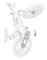
- the externally positioned electronic remote controller 355 or electronic controller 325may be positioned anywhere.
- the electronic remote controller 355 or the electronic controller 325may be mounted on the handlebar 200 .
- the handlebar 200or any other component of a bicycle, may variously contain one or more of the following attached thereto: an electronic controller 325 ; a mechanical remote controller 345 ; and an electronic remote controller 355 .
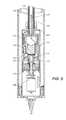
- a motive source M 365is associated with the cam 520 .
- the motive source M 365can comprise any conventional source of torque, including servo-motors and/or mechanical gear drives (neither shown).
- the motive source M 365may be associated with a controller, for example: (a) an electrical wire 360 for connecting motive source M 365 to an externally positioned electronic remote controller 355 ; (b) a mechanical cable 350 for connecting motive source M 365 to an externally positioned mechanical remote controller 345 ; and (c) an electronic controller 325 , such as a CPU, receives control signals from one or more sensors 330 A-C and sends control signals to the motive source M 365 .
- thisis a gradual process that allows control of the return speed of the seat post 300 , prevents over-shoot of the seat post 300 , and allows adjustment even after the valve assembly 445 is in a closed position. Since fluid may no longer flow through the check valve one 510 due to its being in a closed position, the compression movement of the seat post 300 is halted.
- the controller 370is preprogrammed to receive instructions from a voice activated audio detection module 380 mounted on the handlebar 200 or some other area of the bicycle, in which the voice activated audio detection module 380 receives audible position instructions from the rider and translates and transmits these instructions to the controller 370 .
- the voice activated audio detection moduleis preprogrammed to receive a coded language and transmit the received coded language in the form of a position instruction.
- the voice activated audio detection module 380is positioned separate from the set of control levers 205 (which may include any of the following: an electronic remote controller 355 ; a mechanical remote controller 345 ; and an electronic controller 325 ).
- FIG. 14Bdepicts a circuit drawing 1400 including a PID controller 1410 , in accordance with an embodiment.
- the PID controller 1410receives a compression position instruction (represented by “signal 1 ”) 1405 , which would be considered to be the desired position of the seat post 300 .
- a displacement sensorcalculates the actual position (represented by “signal 2 ”) of the seat post 300 .
- Signal 1is subtracted from signal 2 , to attain the displacement error measurement 1415 .
- the gear shifting systemincludes: the controller 1700 ; the gear shifter device 1765 in communication with the controller 1700 ; and a performance sensor in communication with the controller 1700 .
- a suspension modification systemincludes: the controller 1700 ; a suspension device in communication with the controller 1700 ; and a performance sensor in communication with the controller 1700 .
Landscapes
- Engineering & Computer Science (AREA)
- Mechanical Engineering (AREA)
- Physics & Mathematics (AREA)
- General Physics & Mathematics (AREA)
- Automation & Control Theory (AREA)
- General Engineering & Computer Science (AREA)
- Seats For Vehicles (AREA)
Abstract
Description
Claims (29)
Priority Applications (4)
| Application Number | Priority Date | Filing Date | Title |
|---|---|---|---|
| US15/241,964US10472013B2 (en) | 2008-11-25 | 2016-08-19 | Seat post |
| US16/677,329US11021204B2 (en) | 2008-11-25 | 2019-11-07 | Seat post |
| US17/332,685US11897571B2 (en) | 2008-11-25 | 2021-05-27 | Seat post |
| US18/437,248US20240182131A1 (en) | 2008-11-25 | 2024-02-09 | Seat post |
Applications Claiming Priority (16)
| Application Number | Priority Date | Filing Date | Title |
|---|---|---|---|
| US11760808P | 2008-11-25 | 2008-11-25 | |
| US16155209P | 2009-03-19 | 2009-03-19 | |
| US16162009P | 2009-03-19 | 2009-03-19 | |
| US17542209P | 2009-05-04 | 2009-05-04 | |
| US12/626,384US9108098B2 (en) | 2008-11-25 | 2009-11-25 | Methods and apparatus for virtual competition |
| US30207010P | 2010-02-05 | 2010-02-05 | |
| US12/727,915US9140325B2 (en) | 2009-03-19 | 2010-03-19 | Methods and apparatus for selective spring pre-load adjustment |
| US12/773,671US20100276906A1 (en) | 2009-05-04 | 2010-05-04 | Suspension system for a vehicle |
| US36137610P | 2010-07-02 | 2010-07-02 | |
| US13/022,346US10036443B2 (en) | 2009-03-19 | 2011-02-07 | Methods and apparatus for suspension adjustment |
| US13/176,336US8814109B2 (en) | 2010-07-02 | 2011-07-05 | Positive lock adjustable seat post |
| US201161533712P | 2011-09-12 | 2011-09-12 | |
| US13/292,949US20120080279A1 (en) | 2009-03-19 | 2011-11-09 | Methods and apparatus for sag adjustment |
| US201261638406P | 2012-04-25 | 2012-04-25 | |
| US13/844,516US9422018B2 (en) | 2008-11-25 | 2013-03-15 | Seat post |
| US15/241,964US10472013B2 (en) | 2008-11-25 | 2016-08-19 | Seat post |
Related Parent Applications (1)
| Application Number | Title | Priority Date | Filing Date |
|---|---|---|---|
| US13/844,516ContinuationUS9422018B2 (en) | 2008-11-25 | 2013-03-15 | Seat post |
Related Child Applications (1)
| Application Number | Title | Priority Date | Filing Date |
|---|---|---|---|
| US16/677,329ContinuationUS11021204B2 (en) | 2008-11-25 | 2019-11-07 | Seat post |
Publications (2)
| Publication Number | Publication Date |
|---|---|
| US20160355226A1 US20160355226A1 (en) | 2016-12-08 |
| US10472013B2true US10472013B2 (en) | 2019-11-12 |
Family
ID=49002039
Family Applications (4)
| Application Number | Title | Priority Date | Filing Date |
|---|---|---|---|
| US13/844,516Active2031-05-06US9422018B2 (en) | 2008-11-25 | 2013-03-15 | Seat post |
| US15/241,964ActiveUS10472013B2 (en) | 2008-11-25 | 2016-08-19 | Seat post |
| US16/677,329ActiveUS11021204B2 (en) | 2008-11-25 | 2019-11-07 | Seat post |
| US17/332,685ActiveUS11897571B2 (en) | 2008-11-25 | 2021-05-27 | Seat post |
Family Applications Before (1)
| Application Number | Title | Priority Date | Filing Date |
|---|---|---|---|
| US13/844,516Active2031-05-06US9422018B2 (en) | 2008-11-25 | 2013-03-15 | Seat post |
Family Applications After (2)
| Application Number | Title | Priority Date | Filing Date |
|---|---|---|---|
| US16/677,329ActiveUS11021204B2 (en) | 2008-11-25 | 2019-11-07 | Seat post |
| US17/332,685ActiveUS11897571B2 (en) | 2008-11-25 | 2021-05-27 | Seat post |
Country Status (1)
| Country | Link |
|---|---|
| US (4) | US9422018B2 (en) |
Cited By (4)
| Publication number | Priority date | Publication date | Assignee | Title |
|---|---|---|---|---|
| US20200062327A1 (en)* | 2018-06-28 | 2020-02-27 | Specialized Bicycle Components, Inc. | In-frame mounted bicycle monitoring device |
| US11505024B2 (en) | 2019-10-08 | 2022-11-22 | Off-Road Research LLC | Electronically controlled external damper reservoir |
| US12269547B2 (en) | 2022-11-21 | 2025-04-08 | Sram, Llc | Seat post assembly with automatic power connector |
| US12291297B2 (en) | 2022-11-21 | 2025-05-06 | Sram, Llc | Height adjustable seat posts for bicycles |
Families Citing this family (103)
| Publication number | Priority date | Publication date | Assignee | Title |
|---|---|---|---|---|
| US10060499B2 (en) | 2009-01-07 | 2018-08-28 | Fox Factory, Inc. | Method and apparatus for an adjustable damper |
| US10047817B2 (en) | 2009-01-07 | 2018-08-14 | Fox Factory, Inc. | Method and apparatus for an adjustable damper |
| US11306798B2 (en) | 2008-05-09 | 2022-04-19 | Fox Factory, Inc. | Position sensitive suspension damping with an active valve |
| US20100170760A1 (en) | 2009-01-07 | 2010-07-08 | John Marking | Remotely Operated Bypass for a Suspension Damper |
| US8857580B2 (en) | 2009-01-07 | 2014-10-14 | Fox Factory, Inc. | Remotely operated bypass for a suspension damper |
| US20120305350A1 (en) | 2011-05-31 | 2012-12-06 | Ericksen Everet O | Methods and apparatus for position sensitive suspension damping |
| US8627932B2 (en) | 2009-01-07 | 2014-01-14 | Fox Factory, Inc. | Bypass for a suspension damper |
| US9033122B2 (en) | 2009-01-07 | 2015-05-19 | Fox Factory, Inc. | Method and apparatus for an adjustable damper |
| US9452654B2 (en) | 2009-01-07 | 2016-09-27 | Fox Factory, Inc. | Method and apparatus for an adjustable damper |
| US8328454B2 (en) | 2008-06-30 | 2012-12-11 | Specialized Bicycle Components, Inc. | Vertically adjustable bicycle assembly |
| US8393446B2 (en) | 2008-08-25 | 2013-03-12 | David M Haugen | Methods and apparatus for suspension lock out and signal generation |
| EP3666347B1 (en) | 2008-11-25 | 2021-10-20 | Fox Factory, Inc. | Computer usable storage medium for virtual competition |
| US10036443B2 (en) | 2009-03-19 | 2018-07-31 | Fox Factory, Inc. | Methods and apparatus for suspension adjustment |
| US9422018B2 (en) | 2008-11-25 | 2016-08-23 | Fox Factory, Inc. | Seat post |
| US9140325B2 (en) | 2009-03-19 | 2015-09-22 | Fox Factory, Inc. | Methods and apparatus for selective spring pre-load adjustment |
| US12122205B2 (en) | 2009-01-07 | 2024-10-22 | Fox Factory, Inc. | Active valve for an internal bypass |
| US9038791B2 (en) | 2009-01-07 | 2015-05-26 | Fox Factory, Inc. | Compression isolator for a suspension damper |
| US10821795B2 (en) | 2009-01-07 | 2020-11-03 | Fox Factory, Inc. | Method and apparatus for an adjustable damper |
| US11299233B2 (en) | 2009-01-07 | 2022-04-12 | Fox Factory, Inc. | Method and apparatus for an adjustable damper |
| US8936139B2 (en) | 2009-03-19 | 2015-01-20 | Fox Factory, Inc. | Methods and apparatus for suspension adjustment |
| EP2312180B1 (en) | 2009-10-13 | 2019-09-18 | Fox Factory, Inc. | Apparatus for controlling a fluid damper |
| US8672106B2 (en) | 2009-10-13 | 2014-03-18 | Fox Factory, Inc. | Self-regulating suspension |
| US10697514B2 (en) | 2010-01-20 | 2020-06-30 | Fox Factory, Inc. | Remotely operated bypass for a suspension damper |
| EP2402239B1 (en) | 2010-07-02 | 2020-09-02 | Fox Factory, Inc. | Adjustable seat post |
| EP2683599B1 (en) | 2011-03-11 | 2019-04-24 | Specialized Bicycle Components, Inc. | Adjustable assembly for a bicycle |
| US10246155B2 (en) | 2011-03-11 | 2019-04-02 | Specialized Bicycle Components, Inc. | Adjustable assembly for a bicycle |
| EP3929459A1 (en) | 2011-09-12 | 2021-12-29 | Fox Factory, Inc. | Methods and apparatus for suspension set up |
| US9339691B2 (en) | 2012-01-05 | 2016-05-17 | Icon Health & Fitness, Inc. | System and method for controlling an exercise device |
| US11279199B2 (en) | 2012-01-25 | 2022-03-22 | Fox Factory, Inc. | Suspension damper with by-pass valves |
| US10330171B2 (en) | 2012-05-10 | 2019-06-25 | Fox Factory, Inc. | Method and apparatus for an adjustable damper |
| EP3192731B1 (en)* | 2012-08-21 | 2019-11-20 | Gustav Magenwirth GmbH & Co. KG | Electronically controlled suspension system, method and computer program |
| WO2014153158A1 (en) | 2013-03-14 | 2014-09-25 | Icon Health & Fitness, Inc. | Strength training apparatus with flywheel and related methods |
| US9157523B2 (en)* | 2013-05-27 | 2015-10-13 | Shimano Inc. | Bicycle component actuation apparatus |
| CN203601454U (en)* | 2013-10-28 | 2014-05-21 | 久鼎金属实业股份有限公司 | Adjustable seat tube assembly of bicycle |
| CN105848733B (en) | 2013-12-26 | 2018-02-13 | 爱康保健健身有限公司 | Magnetic resistance mechanism in hawser apparatus |
| US10433612B2 (en) | 2014-03-10 | 2019-10-08 | Icon Health & Fitness, Inc. | Pressure sensor to quantify work |
| WO2015191445A1 (en) | 2014-06-09 | 2015-12-17 | Icon Health & Fitness, Inc. | Cable system incorporated into a treadmill |
| WO2015195965A1 (en) | 2014-06-20 | 2015-12-23 | Icon Health & Fitness, Inc. | Post workout massage device |
| GB201512713D0 (en)* | 2014-08-01 | 2015-08-26 | Ford Global Tech Llc | Electric bicycle |
| CA2959649C (en) | 2014-08-26 | 2023-09-26 | Nine Point Eight Inc. | Systems and methods for supporting telescoping elements |
| US9452798B2 (en)* | 2014-10-31 | 2016-09-27 | Shimano Inc. | Bicycle seatpost assembly |
| US20160153515A1 (en)* | 2014-12-02 | 2016-06-02 | Cycling Sports Group, Inc. | Valve Assembly For Bicycle Suspension System |
| EP3233616B1 (en)* | 2014-12-18 | 2020-05-27 | Specialized Bicycle Components, Inc. | Saddle adjustment system |
| TWM499358U (en)* | 2014-12-30 | 2015-04-21 | Lee Chi Entpr Co Ltd | Internal sliding groove type saddle combining and tightening structure |
| US10391361B2 (en) | 2015-02-27 | 2019-08-27 | Icon Health & Fitness, Inc. | Simulating real-world terrain on an exercise device |
| DE102015204880B4 (en)* | 2015-03-18 | 2018-03-29 | Robert Bosch Gmbh | Method for controlling a drive to move the height of a saddle of a bicycle depending on the situation, as well as a device provided for this purpose |
| US10336400B2 (en)* | 2015-03-27 | 2019-07-02 | Shimano Inc. | Bicycle transmission control apparatus |
| US10351193B2 (en) | 2015-08-07 | 2019-07-16 | Humanchine Company | Holding device for positional control of a shaft |
| US10040499B2 (en) | 2015-10-01 | 2018-08-07 | Shimano Inc. | Electrical seatpost assembly |
| US10759483B2 (en) | 2015-10-01 | 2020-09-01 | Shimano Inc. | Bicycle and electrical seatpost assembly |
| US9540063B1 (en)* | 2015-10-09 | 2017-01-10 | Shimano Inc. | Bicycle actuation structure and bicycle seatpost assembly |
| US10150526B2 (en)* | 2015-10-16 | 2018-12-11 | Specialized Bicycle Components, Inc. | Bicycle saddle post suspension |
| US9963181B2 (en) | 2015-10-19 | 2018-05-08 | Fox Factory, Inc. | Infinite adjust seat post with pressure relief valve |
| US10493349B2 (en) | 2016-03-18 | 2019-12-03 | Icon Health & Fitness, Inc. | Display on exercise device |
| US10625137B2 (en) | 2016-03-18 | 2020-04-21 | Icon Health & Fitness, Inc. | Coordinated displays in an exercise device |
| US10272317B2 (en) | 2016-03-18 | 2019-04-30 | Icon Health & Fitness, Inc. | Lighted pace feature in a treadmill |
| US10737546B2 (en) | 2016-04-08 | 2020-08-11 | Fox Factory, Inc. | Electronic compression and rebound control |
| US10131391B2 (en)* | 2016-05-25 | 2018-11-20 | Shimano Inc. | Bicycle seatpost assembly |
| CN105857451A (en)* | 2016-06-13 | 2016-08-17 | 京东方科技集团股份有限公司 | Intelligent bicycle |
| US11136083B2 (en)* | 2016-09-20 | 2021-10-05 | Shimano Inc. | Bicycle telescopic apparatus |
| US10722775B2 (en)* | 2016-09-27 | 2020-07-28 | Adidas Ag | Robotic training systems and methods |
| US10671705B2 (en) | 2016-09-28 | 2020-06-02 | Icon Health & Fitness, Inc. | Customizing recipe recommendations |
| JP2018052357A (en)* | 2016-09-29 | 2018-04-05 | 株式会社シマノ | Bicycle operation device |
| US10358180B2 (en)* | 2017-01-05 | 2019-07-23 | Sram, Llc | Adjustable seatpost |
| US9957008B1 (en)* | 2017-03-06 | 2018-05-01 | Taiwan Hodaka Industrial Co., Ltd. | Bicycle seatpost structure |
| US10889346B2 (en)* | 2017-08-18 | 2021-01-12 | Shimano Inc. | Electric twist-grip operating device |
| US10829173B2 (en) | 2017-12-21 | 2020-11-10 | Shimano Inc. | Bicycle seatpost assembly |
| US10618589B2 (en)* | 2017-12-21 | 2020-04-14 | Shimano Inc. | Bicycle seatpost assembly |
| US11180211B2 (en)* | 2017-12-27 | 2021-11-23 | Shimano Inc. | Bicycle telescopic apparatus |
| US11066118B2 (en) | 2018-01-26 | 2021-07-20 | Shimano Inc. | Bicycle seatpost system |
| US10450022B2 (en) | 2018-01-31 | 2019-10-22 | David Watson | Device for adjusting a seat position of a bicycle seat |
| WO2019195351A1 (en) | 2018-04-02 | 2019-10-10 | Wolf Tooth Components, LLC | Linear actuator system |
| US11180212B2 (en)* | 2018-07-17 | 2021-11-23 | Shimano Inc. | Fluid flow control structure for a telescopic apparatus of a human powered vehicle |
| US11046389B2 (en) | 2018-08-21 | 2021-06-29 | Specialized Bicycle Components, Inc. | Ebike battery mount |
| US12043344B2 (en) | 2018-08-21 | 2024-07-23 | Specialized Bicycle Components, Inc. | Bicycle with battery, motor and motor mount, wire routing, speed sensor, and dropper seat post |
| CN109131652B (en)* | 2018-08-21 | 2020-11-03 | 浙江富兴服装有限公司 | Shared bicycle saddle |
| US11124259B2 (en) | 2018-08-21 | 2021-09-21 | Specialized Bicycle Components, Inc. | Bicycle with housing loop stay |
| US11117635B2 (en) | 2018-10-03 | 2021-09-14 | Motion Instruments Inc. | System for balancing dampening forces on a suspension system |
| US11649002B2 (en)* | 2018-11-02 | 2023-05-16 | Sram, Llc | Seat post control system |
| DE102018219057B3 (en) | 2018-11-08 | 2020-01-02 | Robert Bosch Gmbh | Seat post for a bike |
| US11447201B2 (en)* | 2019-01-31 | 2022-09-20 | Fox Factory, Inc. | Dropper seatpost head assembly |
| US11780519B2 (en) | 2019-03-26 | 2023-10-10 | Shimano Inc. | Telescopic apparatus controller, telescopic apparatus operating system, and telescopic apparatus |
| US11518477B2 (en)* | 2019-05-31 | 2022-12-06 | Shimano Inc. | Actuation controller and actuation system |
| JP7321873B2 (en) | 2019-10-09 | 2023-08-07 | 株式会社シマノ | Control device for man-powered vehicles |
| EP3809012B1 (en)* | 2019-10-18 | 2025-06-11 | Öhlins Racing AB | Front fork position-dependent damping for bicycles and motorcycles |
| US11975792B2 (en)* | 2019-11-26 | 2024-05-07 | Fox Factory, Inc. | Selecting different suspension tunes via a manually operated switch |
| US11724769B2 (en) | 2019-12-17 | 2023-08-15 | Sram, Llc | Bicycle suspension components and electronic control devices |
| TW202216518A (en) | 2020-05-04 | 2022-05-01 | 加拿大商綠房控股有限公司 | Device for adjusting a seat position of a bicycle seat |
| US11745817B2 (en) | 2020-05-28 | 2023-09-05 | Fox Factory, Inc. | Offset bushings and alignment features of a dropper seatpost assembly |
| US11427274B2 (en)* | 2020-08-05 | 2022-08-30 | Foming Bicycle Parts Co., Ltd. | Angle adjustable bicycle saddle |
| US12030575B2 (en) | 2020-10-27 | 2024-07-09 | Shimano Inc. | Rider-posture changing device and control system of human-powered vehicle |
| US20220210650A1 (en) | 2020-12-28 | 2022-06-30 | Fox Factory, Inc. | Wireless switch for an active component |
| US12410868B2 (en) | 2021-02-05 | 2025-09-09 | Fox Factory, Inc. | Rotary flow control valve that requires no linear motion |
| EP4108557B1 (en) | 2021-06-24 | 2025-05-14 | Fox Factory, Inc. | Electronically actuated dropper seatpost |
| JP2023042277A (en)* | 2021-09-14 | 2023-03-27 | 株式会社シマノ | Control device for man power driven vehicle |
| US12269548B2 (en) | 2022-01-21 | 2025-04-08 | Fox Factory, Inc. | Travel adjust system for dropper seatposts |
| TWM640748U (en)* | 2022-04-27 | 2023-05-11 | 凱薩克科技股份有限公司 | Seat height adjustment device |
| TWM636822U (en)* | 2022-08-29 | 2023-01-21 | 巨大機械工業股份有限公司 | Telescopic mechanism |
| TW202502592A (en)* | 2023-06-30 | 2025-01-16 | 凱薩克科技股份有限公司 | Adjustable air oil pressure device |
| US20250033722A1 (en) | 2023-07-27 | 2025-01-30 | Fox Factory, Inc. | Extended seatpost saddle clamp nut |
| US12429074B2 (en) | 2023-09-12 | 2025-09-30 | Fox Factory, Inc. | Internal floating piston |
| US20250084928A1 (en) | 2023-09-12 | 2025-03-13 | Fox Factory, Inc. | Pressure balanced valve with integral pressure relief function |
| TWI883827B (en)* | 2024-02-19 | 2025-05-11 | 懂捷智慧科技有限公司 | Wireless controller |
Citations (314)
| Publication number | Priority date | Publication date | Assignee | Title |
|---|---|---|---|---|
| US435995A (en) | 1890-09-09 | John boyd dunlop | ||
| US1923011A (en) | 1928-07-05 | 1933-08-15 | Rollin H Moulton | Shock absorber |
| US1948600A (en) | 1931-08-15 | 1934-02-27 | Walter B Templeton | Adjustable dance floor support |
| US2259437A (en) | 1939-03-01 | 1941-10-21 | Peter P Dean | Control apparatus |
| US2492331A (en) | 1947-03-27 | 1949-12-27 | Spring Russell Mason | Shock absorber valve regulator |
| US2540525A (en) | 1947-05-09 | 1951-02-06 | Grinnell Corp | Spring support |
| US2697600A (en) | 1949-07-20 | 1954-12-21 | Jean A Gregoire | Suspension means for vehicles |
| US2705119A (en) | 1949-12-06 | 1955-03-29 | Ridge Tool Co | Pipe support stand |
| US2784962A (en) | 1954-05-04 | 1957-03-12 | Grinnell Corp | Adjustment scales for spring devices |
| US2879971A (en) | 1954-10-20 | 1959-03-31 | Honeywell Regulator Co | Valve apparatus |
| US2991804A (en) | 1959-05-27 | 1961-07-11 | Gen Motors Corp | Air suspension and control apparatus therefor |
| US3085530A (en) | 1958-10-22 | 1963-04-16 | Floyd M Williamson | Hydraulic press ram cushion |
| US3087583A (en) | 1959-10-07 | 1963-04-30 | Otis Elevator Co | Extended roller guide for elevators |
| US3206153A (en) | 1963-02-25 | 1965-09-14 | Bjorgensen Designs Ltd | Tilt swivel mechanism for chairs |
| US3284076A (en) | 1964-07-20 | 1966-11-08 | Thomas & Betts Corp | Adjustable tensioning means for tools |
| US3528700A (en) | 1968-03-27 | 1970-09-15 | Albert Kamin | Adjustable clamp and spring arrangement for seat support |
| US3560033A (en) | 1969-02-25 | 1971-02-02 | Homer A Barkus | Telescopic positive lock strut |
| US3575442A (en) | 1969-07-14 | 1971-04-20 | Gen Motors Corp | Semiautomatic door actuated vehicle leveling system |
| US3603575A (en) | 1969-07-07 | 1971-09-07 | Chapman Performance Products I | Adjustable vehicle-stabilizing unit |
| US3650033A (en) | 1968-10-26 | 1972-03-21 | Siemens Ag | Dental treatment units |
| US3701544A (en) | 1970-10-13 | 1972-10-31 | Frank M Stankovich | Motorcycle front end assembly |
| US3784228A (en) | 1971-10-22 | 1974-01-08 | Hoesch Ag | Regulating apparatus for a fluid controlled car suspension |
| US3830482A (en) | 1972-10-17 | 1974-08-20 | K Norris | Adjustable coil spring lifter |
| US3903613A (en) | 1974-02-07 | 1975-09-09 | Aaron M Bisberg | Bicycle training device for simulating the movement of a bicycle equipped with gears |
| US4036335A (en) | 1971-09-13 | 1977-07-19 | Arnold A. Cowan | Adjustable shock absorber |
| US4103881A (en) | 1976-09-13 | 1978-08-01 | Simich Irene C | Load regulator |
| FR2432424A1 (en) | 1978-08-02 | 1980-02-29 | Micmo | Lock for bicycle saddle post - has eccentric spindle working in transverse bore in pull rod which has locking member at one end |
| US4348016A (en) | 1978-09-06 | 1982-09-07 | Lucien Milly | Process and device for suspension of vehicle wheels |
| JPS57173632A (en) | 1981-04-21 | 1982-10-26 | Kayaba Ind Co Ltd | Hydraulic buffer |
| JPS57173632U (en) | 1981-04-28 | 1982-11-01 | ||
| JPS57182506A (en) | 1981-05-01 | 1982-11-10 | Kayaba Ind Co Ltd | Damping force controller of hydraulic pressure buffer |
| US4366969A (en) | 1981-07-21 | 1983-01-04 | Moog Automotive, Inc. | Adjustable leveling suspension unit for vehicles |
| US4474363A (en) | 1982-03-20 | 1984-10-02 | Toyota Jidosha Kabushiki Kaisha | Suspension for automobile |
| US4630818A (en) | 1985-06-27 | 1986-12-23 | Tunturipyora Oy | Torque metering device for a bicycle-type ergometer |
| US4634142A (en) | 1983-08-15 | 1987-01-06 | C & K Venture Income I-Coast | Computer optimized adaptive suspension system |
| US4647068A (en) | 1985-01-16 | 1987-03-03 | Toyota Jidosha Kabushiki Kaisha | Rear suspension controller |
| US4655440A (en) | 1984-04-14 | 1987-04-07 | Robert Bosch Gmbh | Apparatus for controlling vehicle spring firmness |
| US4657280A (en) | 1983-10-27 | 1987-04-14 | Honda Giken Kogyo Kabushiki Kaisha | System for controlling the damping rate of a vehicle suspension |
| US4732244A (en) | 1986-01-30 | 1988-03-22 | White Power Production B.V. | Hydraulic shock damper assembly for use in vehicles |
| US4744444A (en) | 1978-04-12 | 1988-05-17 | Craig L. Gillingham | Shock absorber |
| US4773671A (en) | 1986-02-21 | 1988-09-27 | Honda Giken Kogyo Kabushiki Kaisha | Method of controlling damping force of damper |
| EP0304801A2 (en) | 1987-08-25 | 1989-03-01 | Trw Inc. | Strut with controlled variable damping rate |
| JPH01106721A (en) | 1987-10-20 | 1989-04-24 | Tokico Ltd | Shock absorber |
| US4830395A (en) | 1988-02-22 | 1989-05-16 | Foley Jimmy D | Stabilizer system for racing cars |
| DE3738048A1 (en) | 1987-11-09 | 1989-05-18 | Rexroth Mannesmann Gmbh | Device for damping the self-movements of the masses of a linear two-mass oscillator |
| US4836578A (en) | 1987-12-28 | 1989-06-06 | Ford Motor Company | High resolution digital suspension position sensor for automotive vehicle |
| US4938228A (en) | 1989-02-15 | 1990-07-03 | Righter William H | Wrist worn heart rate monitor |
| US4949262A (en) | 1987-09-03 | 1990-08-14 | Kabushiki Kaisha Toyota Chuo Kenkyusho | Electronic controlled fluid suspension system with an advance control and a feedback control of a vehicle attitude |
| US4949989A (en) | 1988-04-19 | 1990-08-21 | Atsugi Motor Parts Co., Ltd. | Automotive suspension system with variable suspension characteristics and variable damping force shock absorber therefor |
| US4984819A (en) | 1988-04-14 | 1991-01-15 | Atsugi Motor Parts Company, Limited | Automotive suspension system and shock absorber therefor |
| US5027303A (en) | 1989-07-17 | 1991-06-25 | Witte Don C | Measuring apparatus for pedal-crank assembly |
| US5031455A (en) | 1989-09-05 | 1991-07-16 | Cline David J | Bicycle power meter |
| US5044614A (en) | 1990-02-22 | 1991-09-03 | Rau John A | Shock absorber spring adjuster |
| US5060959A (en) | 1988-10-05 | 1991-10-29 | Ford Motor Company | Electrically powered active suspension for a vehicle |
| US5074624A (en) | 1988-10-05 | 1991-12-24 | Knorr-Bremse Ag | Bogie vehicle with electrohydraulic brakes and hydropneumatic suspension |
| US5094325A (en) | 1990-06-21 | 1992-03-10 | Smith J Marlow | Vehicle shock absorber assembly |
| US5105918A (en) | 1989-10-23 | 1992-04-21 | Nippondenso Co., Ltd. | Detection of damping force for shock absorber control |
| JPH04203540A (en) | 1990-11-29 | 1992-07-24 | Mazda Motor Corp | Damping force adjusting type hydraulic buffer |
| US5152547A (en) | 1990-11-02 | 1992-10-06 | Davis Leo W | Dual piston strut |
| US5203584A (en) | 1990-04-17 | 1993-04-20 | Mazada Motor Corporation | Suspension system for a vehicle |
| JPH05149364A (en) | 1991-11-30 | 1993-06-15 | Tokico Ltd | Damping force adjustable hydraulic shock absorber |
| EP0552568A1 (en) | 1991-12-27 | 1993-07-28 | Bridgestone Corporation | A process and an apparatus for controlling vibration damping force in a vibration damping device |
| US5236169A (en) | 1991-08-12 | 1993-08-17 | T.J.S.W. Inc. | Adjustable height shock absorbing bicycle seat mounting post assembly |
| US5265902A (en) | 1992-02-25 | 1993-11-30 | Lewis Roy A | Vehicle suspension member |
| US5283733A (en) | 1992-03-24 | 1994-02-01 | Colley Russell H | Computer on-line golf scoring device |
| US5348112A (en) | 1993-02-19 | 1994-09-20 | Works Performance Products, Inc. | Motorcycle height adjuster |
| US5390949A (en) | 1993-03-08 | 1995-02-21 | The University Of Toledo | Active suspension systems and components using piezoelectric sensing and actuation devices |
| US5503258A (en) | 1994-08-16 | 1996-04-02 | Ford Motor Co. | Hydraulic shock absorber |
| US5542150A (en) | 1994-08-30 | 1996-08-06 | Tu; A-Shih | Simple push button type link control structure |
| US5551674A (en) | 1994-07-06 | 1996-09-03 | Johnsen; Thore K. | Adjustable resilient support device |
| US5553836A (en) | 1995-05-11 | 1996-09-10 | Patentials Incorporated | Adjustable suspension system |
| US5592401A (en) | 1995-02-28 | 1997-01-07 | Virtual Technologies, Inc. | Accurate, rapid, reliable position sensing using multiple sensing technologies |
| US5598337A (en) | 1992-09-30 | 1997-01-28 | Mazda Motor Corporation | Suspension apparatus with driving state feedback for vehicles |
| US5697477A (en) | 1994-10-07 | 1997-12-16 | Nifco Inc. | Air damper |
| US5722645A (en) | 1995-06-16 | 1998-03-03 | Dr. Ing. H. C. F. Porsche Ag | Arrangement for influencing coil spring travel |
| US5803443A (en) | 1997-09-24 | 1998-09-08 | Chang; Wu-Sung | Shock absorber for motor vehicles |
| WO1998040231A2 (en) | 1997-03-13 | 1998-09-17 | Cannondale Corporation | Electronic suspension system for a wheeled vehicle |
| US5816281A (en) | 1997-02-21 | 1998-10-06 | Mixon; Charles S. | Brake bleeding tool |
| US5828843A (en) | 1996-03-21 | 1998-10-27 | Mpath Interactive, Inc. | Object-oriented method for matching clients together with servers according to attributes included in join request |
| US5826935A (en)* | 1997-11-19 | 1998-10-27 | Defreitas; Renato J. | Automatic bicycle seat adjuster |
| US5829733A (en) | 1996-11-29 | 1998-11-03 | Becker; William R. | Adjustable height shock absorbing bicycle seat mounting assembly |
| US5850352A (en) | 1995-03-31 | 1998-12-15 | The Regents Of The University Of California | Immersive video, including video hypermosaicing to generate from multiple video views of a scene a three-dimensional video mosaic from which diverse virtual video scene images are synthesized, including panoramic, scene interactive and stereoscopic images |
| US5853071A (en) | 1997-07-10 | 1998-12-29 | Mcdonnell Douglas Corporation | Bleed valve for bleeding fluid from a hydraulic circuit |
| WO1999006231A1 (en) | 1997-07-31 | 1999-02-11 | Outback Bicycles, Inc. | Continuosly compensating bicycle suspension system |
| US5884921A (en) | 1996-08-29 | 1999-03-23 | Toyota Jidosha Kabushiki Kaisha | Electric control apparatus for damper device in suspension system of automotive vehicle |
| US5954318A (en) | 1997-05-01 | 1999-09-21 | Kluhsman Machine, Inc. | Suspension assembly having detent nut adjustment |
| US5999868A (en) | 1996-02-26 | 1999-12-07 | Board Of Regents The University Of Texas System | Constant force suspension, near constant force suspension, and associated control algorithms |
| US6013007A (en) | 1998-03-26 | 2000-01-11 | Liquid Spark, Llc | Athlete's GPS-based performance monitor |
| US6017047A (en) | 1997-04-28 | 2000-01-25 | Hoose; Howard | Vehicle suspension |
| US6035979A (en) | 1996-06-21 | 2000-03-14 | Fichtel & Sachs Ag | Vibration damper and a vibration damper with a damping valve having an adjustable damping force |
| US6050583A (en) | 1997-01-13 | 2000-04-18 | Bohn; David D. | Electronically controlled bicycle suspension apparatus |
| US6058340A (en) | 1993-12-28 | 2000-05-02 | Tokico Ltd. | Suspension control apparatus |
| WO2000027658A1 (en) | 1998-11-11 | 2000-05-18 | Kenmar Company Trust | Suspension control unit and control valve |
| US6105988A (en) | 1997-07-16 | 2000-08-22 | Rockshox, Inc. | Adjustable suspension system having positive and negative springs |
| US6135434A (en) | 1998-02-03 | 2000-10-24 | Fox Factory, Inc. | Shock absorber with positive and negative gas spring chambers |
| US6152856A (en) | 1996-05-08 | 2000-11-28 | Real Vision Corporation | Real time simulation using position sensing |
| US6219045B1 (en) | 1995-11-13 | 2001-04-17 | Worlds, Inc. | Scalable virtual world chat client-server system |
| US6244398B1 (en) | 1997-05-15 | 2001-06-12 | K2 Bike Inc. | Shock absorber with variable bypass damping |
| US6254067B1 (en) | 1999-08-02 | 2001-07-03 | Giant Manufacturing Co., Ltd. | Fluid regulating device for use with a hydraulic cylinder to obtain a variable shock absorbing effect |
| US20010022621A1 (en) | 2000-03-20 | 2001-09-20 | Squibbs Robert Francis | Camera with user identity data |
| EP1138530A2 (en) | 2000-03-27 | 2001-10-04 | Bose Corporation | Surface vehicle vertical trajectory planning |
| US20010030408A1 (en) | 2000-01-13 | 2001-10-18 | Hiroyuki Miyoshi | Bicycle suspension |
| US6311962B1 (en) | 1998-02-03 | 2001-11-06 | Fox Factory, Inc. | Shock absorber with external air cylinder spring |
| US20010055373A1 (en) | 2000-06-14 | 2001-12-27 | Kabushiki Kaisha Toshiba | Information processing system, information device and information processing device |
| US6336648B1 (en) | 1997-12-15 | 2002-01-08 | David D. Bohn | Electronically controlled anti-dive suspension apparatus for two-wheeled vehicles |
| US6343807B1 (en) | 2001-01-19 | 2002-02-05 | Answer Products, Inc. | Multi-travel suspension fork for cycles |
| US20020032508A1 (en) | 2000-07-31 | 2002-03-14 | Toru Uchino | Suspension control system |
| US6359837B1 (en) | 1999-06-30 | 2002-03-19 | Casio Computer Co., Ltd. | Camera, camera system, information recording system, timepiece, and link system for camera and timepiece |
| EP1188661A2 (en) | 2000-09-13 | 2002-03-20 | Shimano Inc. | Automatic shifting control device for a bicycle |
| US6360857B1 (en) | 1999-03-19 | 2002-03-26 | Fox Factory, Inc. | Damping adjuster for shock absorber |
| US20020045987A1 (en) | 2000-07-13 | 2002-04-18 | Tadahiro Ohata | Digital broadcast signal processing apparatus and digital broadcast signal processing method |
| US6378885B1 (en) | 1998-03-02 | 2002-04-30 | Anthony S. Ellsworth | Bicycle suspension apparatus and related method |
| US6378816B1 (en) | 1999-06-04 | 2002-04-30 | Joel W. Pfister | Linear motion table leg |
| US20020050112A1 (en) | 2000-11-02 | 2002-05-02 | Okin Gesselschaft Fur Antriebstechnik Mbh & Co. Kg | Telescopic column |
| US20020050518A1 (en) | 1997-12-08 | 2002-05-02 | Roustaei Alexander R. | Sensor array |
| US20020055422A1 (en) | 1995-05-18 | 2002-05-09 | Matthew Airmet | Stationary exercise apparatus adaptable for use with video games and including springed tilting features |
| US6389341B1 (en) | 2001-01-12 | 2002-05-14 | Davis Family Irrevocable Trust | Control system for a vehicle suspension |
| US6390747B1 (en) | 1999-09-24 | 2002-05-21 | Alfred Commins | Shrinkage compensator for building tiedowns |
| US6412788B1 (en) | 1999-03-31 | 2002-07-02 | Tokico Ltd. | Suspension control system |
| US6418360B1 (en) | 1999-01-08 | 2002-07-09 | Shockware | Sensor structure for measuring vehicle suspension related information |
| US20020089107A1 (en) | 2000-12-29 | 2002-07-11 | You-Seok Koh | Motor controlled suspension system for adjusting the height of a vehicle body and a damping force |
| US6427812B2 (en) | 1997-07-08 | 2002-08-06 | Active Control Experts, Inc. | Damper and valve |
| US20020113347A1 (en) | 2000-05-08 | 2002-08-22 | Lorin Robbins | Adjustable shock absorber |
| EP1241087A1 (en) | 2001-03-13 | 2002-09-18 | Shimano Inc. | Bicycle suspension |
| US6458060B1 (en) | 1999-07-08 | 2002-10-01 | Icon Ip, Inc. | Systems and methods for interaction with exercise device |
| US20020187867A1 (en) | 2001-06-07 | 2002-12-12 | Shimano Inc. | Hydraulic gear shift mechanism |
| US20020185581A1 (en)* | 2001-06-11 | 2002-12-12 | Trask Brian C. | Bicycle seat elevation adjuster |
| US20030001358A1 (en) | 2001-07-02 | 2003-01-02 | Becker William M. | Bicycle fork cartridge assembly |
| US20030040348A1 (en) | 2001-08-21 | 2003-02-27 | Martens Mark Hugo | Graphical workout feedback system |
| US20030054327A1 (en) | 2001-09-20 | 2003-03-20 | Evensen Mark H. | Repetitive motion feedback system and method of practicing a repetitive motion |
| US20030065430A1 (en) | 2001-10-01 | 2003-04-03 | Jianbo Lu | Attitude sensing system for an automotive vehicle |
| US20030128275A1 (en) | 2001-12-03 | 2003-07-10 | Maguire James F. | Mobile traffic camera system |
| US6609686B2 (en) | 2002-01-18 | 2003-08-26 | Tam Srl | Adjustable support apparatus |
| WO2003070546A1 (en) | 2002-02-22 | 2003-08-28 | Noboru Iwayama | Elevating mechanism of saddle and bicycle having that mechanism |
| US20030160369A1 (en) | 2002-01-11 | 2003-08-28 | Laplante John A. | Semi-active shock absorber control system |
| US6623389B1 (en) | 1999-11-23 | 2003-09-23 | Valentino Campagnolo | Gear shift device for bicycles |
| US20030191567A1 (en) | 2002-04-05 | 2003-10-09 | Gentilcore Michael Leonard | Bicycle data acquisition |
| EP1355209A1 (en) | 2002-04-18 | 2003-10-22 | Ford Global Technologies, LLC | Vehicle control system |
| US20040004659A1 (en) | 2002-07-02 | 2004-01-08 | Foote Jonathan T. | Intersection detection in panoramic video |
| US6701234B1 (en) | 2001-10-18 | 2004-03-02 | Andrew John Vogelsang | Portable motion recording device for motor vehicles |
| EP1394439A1 (en) | 2002-08-29 | 2004-03-03 | Fludicon GmbH | Shock absorbing system for cycles |
| US20040075350A1 (en) | 2002-08-13 | 2004-04-22 | Zf Sachs Ag | Spring support having a height-adjustable spring plate |
| US20040091111A1 (en) | 2002-07-16 | 2004-05-13 | Levy Kenneth L. | Digital watermarking and fingerprinting applications |
| US20040103146A1 (en) | 2002-11-26 | 2004-05-27 | Seung-Hun Park | Method and system for physically exercising with plurality of participants using network |
| EP1449688A2 (en) | 2003-02-18 | 2004-08-25 | Bose Corporation | Surface vehicle vertical trajectory planning |
| US20040208687A1 (en)* | 2003-04-18 | 2004-10-21 | Wayne Sicz | Adjustable bicycle seat post assembly |
| US20040222056A1 (en) | 2001-08-30 | 2004-11-11 | Fox Robert C. | Inertia valve shock absorber |
| US20040256778A1 (en) | 2003-06-17 | 2004-12-23 | Frank Verriet | ATV coil spring preload equalizing adjuster |
| DE10326675A1 (en) | 2003-06-13 | 2004-12-30 | Zf Friedrichshafen Ag | Control device for a motor vehicle's chassis has an electronic control device, a vibration generator, an electronic module and a sensor and/or actuator |
| US6837827B1 (en) | 2003-06-17 | 2005-01-04 | Garmin Ltd. | Personal training device using GPS data |
| US6853955B1 (en) | 2002-12-13 | 2005-02-08 | Garmin Ltd. | Portable apparatus with performance monitoring and audio entertainment features |
| US6857625B2 (en) | 2001-01-15 | 2005-02-22 | Thyssenkrupp Automotive Ag | Spring carrier |
| US20050055156A1 (en) | 2003-08-18 | 2005-03-10 | Koplar Interactive Systems International, L.L.C. | Method and system for embedding device positional data in video signals |
| JP2005119549A (en) | 2003-10-17 | 2005-05-12 | Suzuki Motor Corp | Information exchange system, motorcycle, and device, method and computer program for providing information |
| JP2005119548A (en) | 2003-10-17 | 2005-05-12 | Nissan Motor Co Ltd | Electric vehicle suspension system |
| US20050110229A1 (en) | 2003-10-16 | 2005-05-26 | Ryoji Kimura | Vehicle height adjusting apparatus |
| US6902513B1 (en) | 2002-04-02 | 2005-06-07 | Mcclure Daniel R. | Interactive fitness equipment |
| US6921351B1 (en) | 2001-10-19 | 2005-07-26 | Cybergym, Inc. | Method and apparatus for remote interactive exercise and health equipment |
| US6935157B2 (en) | 2002-10-11 | 2005-08-30 | Larry D. Miller | Anti-bob system for cycles |
| US20050195094A1 (en) | 2004-03-05 | 2005-09-08 | White Russell W. | System and method for utilizing a bicycle computer to monitor athletic performance |
| US20050216186A1 (en) | 2004-03-24 | 2005-09-29 | Dorfman Barnaby M | System and method for displaying images in an online directory |
| US20050227798A1 (en) | 2004-04-08 | 2005-10-13 | Shimano, Inc. | Apparatus for adjusting a position of a bicycle derailleur |
| US20050239601A1 (en) | 2003-08-14 | 2005-10-27 | Tom Thomas | Virtual exercise system and method |
| US6991076B2 (en) | 1999-04-06 | 2006-01-31 | Specialized Bicycle Components, Inc. | Bicycle damping enhancement system |
| US20060040793A1 (en) | 2001-08-21 | 2006-02-23 | Martens Mark H | Exercise system with graphical feedback and method of gauging fitness progress |
| US20060064223A1 (en) | 2004-09-20 | 2006-03-23 | Darrell Voss | Vehicle systems and method |
| US20060065496A1 (en) | 2001-08-30 | 2006-03-30 | Fox Factory, Inc. | Inertia valve shock absorber |
| US20060066074A1 (en)* | 2004-09-29 | 2006-03-30 | Maverick American Llc | Adjustable bicycle seat assemblies and methods of use |
| US7025367B2 (en)* | 2002-10-08 | 2006-04-11 | Mckinnon Paul G | Adjustable air cushion bicycle seat |
| US20060136173A1 (en) | 2004-12-17 | 2006-06-22 | Nike, Inc. | Multi-sensor monitoring of athletic performance |
| US20060163787A1 (en) | 2005-01-14 | 2006-07-27 | Zf Friedrichshafen Ag | Spring carrier with adjustable spring collar |
| US20060176216A1 (en) | 2004-11-17 | 2006-08-10 | Hipskind Jason C | Tracking and timing system |
| US20060175792A1 (en)* | 2004-04-13 | 2006-08-10 | Kimir Seatpost | Adjustable Bicycle Seat Post Assembly |
| US20060185951A1 (en) | 2003-10-20 | 2006-08-24 | Akira Tanaka | Hydraulic shock absorber system for a vehicle |
| US20060213082A1 (en) | 2005-03-23 | 2006-09-28 | Meschan David F | Athletic shoe with removable resilient element |
| US7128693B2 (en) | 2000-04-28 | 2006-10-31 | International Business Machines Corporation | Program and system for managing fitness activity across diverse exercise machines utilizing a portable computer system |
| US20060253210A1 (en) | 2005-03-26 | 2006-11-09 | Outland Research, Llc | Intelligent Pace-Setting Portable Media Player |
| DE102005025811A1 (en) | 2005-06-02 | 2006-12-07 | Kamm, Thomas, Dipl.-Wirtsch.-Ing. (FH) | Electronically controlled/regulated chassis for e.g. bicycle, has sensors measuring front wheel oscillating systems acceleration and chassis`s body acceleration, and adjusting damping coefficients of wheel damping unit or rear damper |
| US20060289258A1 (en) | 2003-07-08 | 2006-12-28 | Fox Robert C | Damper with pressure-sensitive compression damping |
| US20070008096A1 (en) | 2005-05-14 | 2007-01-11 | Tracy Randy L | Reversibly mountable acceleration/de-acceleration warning light |
| US20070006489A1 (en) | 2005-07-11 | 2007-01-11 | Nike, Inc. | Control systems and foot-receiving device products containing such systems |
| US7166064B2 (en) | 1999-07-08 | 2007-01-23 | Icon Ip, Inc. | Systems and methods for enabling two-way communication between one or more exercise devices and computer devices and for enabling users of the one or more exercise devices to competitively exercise |
| US7166062B1 (en) | 1999-07-08 | 2007-01-23 | Icon Ip, Inc. | System for interaction with exercise device |
| US20070021885A1 (en) | 2005-07-25 | 2007-01-25 | Honeywell International Inc. | System and method for personalizing motor vehicle ride or handling characteristics |
| US20070032981A1 (en) | 2005-08-01 | 2007-02-08 | Merkel Carolyn M | Wearable fitness device and fitness device interchangeable with plural wearable articles |
| WO2007017739A2 (en) | 2005-08-08 | 2007-02-15 | Dayton Technologies Limited | Performance monitoring apparatus |
| US20070070069A1 (en) | 2005-09-26 | 2007-03-29 | Supun Samarasekera | System and method for enhanced situation awareness and visualization of environments |
| US7204466B2 (en) | 2005-03-11 | 2007-04-17 | Wu-Hong Hsieh | Quick-acting telescopic tube |
| US20070170688A1 (en) | 2006-01-25 | 2007-07-26 | Watson Edward M | Real-Time Bicycle-Mounted Pedal Stroke Power Analysis System |
| US7255210B2 (en) | 2004-03-24 | 2007-08-14 | Ohlins Racing Ab | Telescopic fork leg for a vehicle, preferably a motorcycle |
| US20070199401A1 (en) | 2006-02-16 | 2007-08-30 | Shimano Inc. | Bicycle shifter |
| US20070213126A1 (en) | 2003-07-14 | 2007-09-13 | Fusion Sport International Pty Ltd | Sports Training And Testing Methods, Appartaus And System |
| US20070239479A1 (en) | 2006-03-29 | 2007-10-11 | Juha Arrasvuori | System and method for gaming |
| US7287760B1 (en) | 2006-08-21 | 2007-10-30 | Bfs Diversified Products, Llc | Vehicle suspension system and method |
| US7292867B2 (en) | 2003-01-16 | 2007-11-06 | Bones In Motion, Inc. | Location-aware fitness training device, methods, and program products that support real-time interactive communication and automated route generation |
| US7293764B2 (en) | 2006-02-03 | 2007-11-13 | Neotek Co., Ltd. | Adjusting mechanism with a helical spring of large diameter |
| JP2007302211A (en) | 2006-05-15 | 2007-11-22 | Toyota Motor Corp | Suspension system |
| US20070272458A1 (en) | 2004-12-09 | 2007-11-29 | Kabushikikaisha Equos Research | Wheel Supporting and Driving Device |
| US20080009992A1 (en) | 2006-06-07 | 2008-01-10 | Honda Motor Co., Ltd. | Control device of variable damping force damper |
| US20080015089A1 (en) | 2006-07-06 | 2008-01-17 | Elisa Hurwitz | Method and apparatus for measuring exercise performance |
| US20080018065A1 (en) | 2004-04-28 | 2008-01-24 | Isuzu Motors Limited | Vehicle Height Adjustment Device And Vehicle Height Adjustment Method |
| US20080059025A1 (en) | 2006-08-29 | 2008-03-06 | Honda Motor Co., Ltd. | Vehicle state estimation system |
| US7363129B1 (en) | 2007-01-05 | 2008-04-22 | Moon Valley Software | Apparatus, system and method that interfaces with an automobile engine control unit |
| US20080096726A1 (en) | 2006-09-07 | 2008-04-24 | Nike, Inc. | Athletic Performance Sensing and/or Tracking Systems and Methods |
| US20080099968A1 (en) | 2006-10-27 | 2008-05-01 | Answer Products, Inc. | Adjustable and progressive coil spring system for two wheeled vehicles |
| US20080109158A1 (en) | 2006-11-02 | 2008-05-08 | Yka Huhtala | Real time performance comparison |
| US20080116622A1 (en)* | 2006-11-16 | 2008-05-22 | Fox Factory, Inc. | Gas spring curve control in an adjustable-volume gas-pressurized device |
| US20080163718A1 (en) | 2007-01-05 | 2008-07-10 | Chiang Cheng Hsun | Ergonomic Road Bicycle Handlebar |
| US7415336B1 (en) | 2002-12-23 | 2008-08-19 | Garmin Ltd. | Methods, devices, and systems for automatic flight logs |
| US20080200310A1 (en) | 2007-02-16 | 2008-08-21 | Nike, Inc. | Real-Time Comparison of Athletic Information |
| WO2008114445A1 (en) | 2007-03-20 | 2008-09-25 | Pioneer Corporation | Training device, training method, training program, and recording medium |
| JP2008238921A (en) | 2007-03-27 | 2008-10-09 | Honda Motor Co Ltd | Control device for damping force variable damper |
| US20080254944A1 (en) | 2007-04-14 | 2008-10-16 | Muri John I | Monitoring of a Wearable Athletic Device |
| US20080303320A1 (en)* | 2007-06-06 | 2008-12-11 | Paul Steven Schranz | Adjustable seat support |
| US20080312799A1 (en) | 2007-06-12 | 2008-12-18 | Campagnolo S.R.L. | Method for electronically controlling a bicycle gearshift and bicycle electronic system |
| US20090048070A1 (en) | 2007-08-17 | 2009-02-19 | Adidas International Marketing B.V. | Sports electronic training system with electronic gaming features, and applications thereof |
| US20090070037A1 (en) | 2007-09-07 | 2009-03-12 | Maritz Inc. | Automated narration and recording for drive events |
| US20090069972A1 (en) | 2007-09-07 | 2009-03-12 | Maritz Inc. | Gps triggered narration and recording for drive events |
| US20090098981A1 (en) | 2007-10-11 | 2009-04-16 | Del Giorno Ralph J | Virtual Trainer |
| US20090118100A1 (en) | 2007-11-02 | 2009-05-07 | Microsoft Corporation | Mobile exercise enhancement with virtual competition |
| US20090121398A1 (en) | 2005-10-07 | 2009-05-14 | Toyota Jidosha Kabushiki Kaisha | Electromagnetic shock absorber for vehicle |
| DE102007063365A1 (en) | 2007-12-29 | 2009-07-02 | Marzell Maier | Device for adjusting the height of a seat post |
| US7558574B2 (en) | 2005-08-03 | 2009-07-07 | Kamilo Feher | Video, voice and location finder wireless communication system |
| US7558313B2 (en) | 1998-08-10 | 2009-07-07 | Kamilo Feher | Cross-correlated TDMA, spread spectrum, CDMA and OFDM systems |
| US20090192673A1 (en)* | 2008-01-24 | 2009-07-30 | Cannondale Bicycle Corporation | Bicycle user interface system and method of operation thereof |
| US7581743B2 (en) | 2005-11-14 | 2009-09-01 | Santa Cruz Bicycles, Inc. | Bicycle rear wheel suspension system with controlled variable shock rate |
| US20090236807A1 (en) | 2008-03-19 | 2009-09-24 | Wootten Dennis K | Methods and apparatus for suspending vehicles |
| US20090258710A1 (en) | 2008-04-09 | 2009-10-15 | Nike, Inc. | System and method for athletic performance race |
| US20090261542A1 (en) | 2008-03-19 | 2009-10-22 | Mcintyre Kevin Joseph | Suspension height adjustment mechanism |
| US20090277736A1 (en) | 2008-05-09 | 2009-11-12 | Specialized Bicycle Components, Inc. | Bicycle damper |
| US20090324327A1 (en)* | 2008-06-30 | 2009-12-31 | Specialized Bicycle Components, Inc. | Vertically adjustable bicycle assembly |
| US20100004097A1 (en) | 2008-07-03 | 2010-01-07 | D Eredita Michael | Online Sporting System |
| US20100010709A1 (en) | 2008-01-24 | 2010-01-14 | Cannondale Bicycle Corporation | Bicycle distributed computing arrangement and method of operation |
| US20100044975A1 (en) | 2008-07-24 | 2010-02-25 | Joshua Benjamin Yablon | Vehicle suspension damper |
| US7673936B2 (en)* | 2007-10-25 | 2010-03-09 | Jung Yu Hsu | Adjustable bicycle seat assembly |
| US7684911B2 (en) | 2005-06-20 | 2010-03-23 | Gm Global Technology Operations, Inc. | Suspension control calibration integrity |
| US7699753B2 (en) | 2004-01-30 | 2010-04-20 | Carl Daikeler | Method and apparatus for creating a virtual workout community |
| US7703585B2 (en) | 2002-06-25 | 2010-04-27 | Fox Factory, Inc. | Integrated and self-contained suspension assembly having an on-the-fly adjustable air spring |
| DE202008015968U1 (en) | 2008-12-03 | 2010-04-29 | Rose Versand Gmbh | Retractable seat post |
| EP2189191A2 (en) | 2008-11-25 | 2010-05-26 | Fox Factory, Inc. | Methods and Apparatus for Virtual Competition |
| US20100139442A1 (en) | 2008-12-09 | 2010-06-10 | Shimano Inc. | Bicycle operating device |
| US7764990B2 (en) | 2004-07-01 | 2010-07-27 | Suunto Oy | Method and device for measuring exercise level during exercise and for measuring fatigue |
| US20100186836A1 (en) | 2007-07-26 | 2010-07-29 | Toyo Seikan Kaisha Ltd. | Coupler |
| US20100198453A1 (en) | 2009-02-02 | 2010-08-05 | Apple Inc. | Systems and Methods for Integrating a Portable Electronic Device with a Bicycle |
| US7775128B2 (en) | 2008-09-04 | 2010-08-17 | Saris Cycling Group, Inc. | Cassette-based power meter |
| US20100207351A1 (en)* | 2009-02-19 | 2010-08-19 | Jochen Klieber | Adjustable-Length Seat Post |
| US20100244340A1 (en) | 2008-03-19 | 2010-09-30 | Wootten Dennis K | Methods and apparatus for combined variable damping and variable spring rate suspension |
| US20100252972A1 (en) | 2009-03-19 | 2010-10-07 | Christopher Paul Cox | Methods and apparatus for selective spring pre-load adjustment |
| US20100276906A1 (en) | 2009-05-04 | 2010-11-04 | Mario Galasso | Suspension system for a vehicle |
| US7837213B2 (en) | 2007-04-16 | 2010-11-23 | Trek Bicycle Corporation | Bicycle rear wheel suspension system |
| DE202010012738U1 (en) | 2009-09-21 | 2010-11-25 | Shimano Inc., Sakai | Electronic control device for a height-adjustable seat post assembly of a bicycle |
| US7841258B2 (en) | 2005-12-01 | 2010-11-30 | Shimano Inc. | Bicycle shift controller |
| US7845602B1 (en) | 2006-02-09 | 2010-12-07 | Primos, Inc. | Telescoping support stand apparatus |
| US20100308628A1 (en)* | 2009-06-05 | 2010-12-09 | Jung Yu Hsu | Adjustment device for bicycle seat |
| US20100314917A1 (en)* | 2009-06-16 | 2010-12-16 | Hsieh Shu-Erh | Saddle Adjusting Device |
| US7857325B2 (en) | 2005-12-16 | 2010-12-28 | Srats, Inc. | Adjustable-height suspension system |
| US20100327542A1 (en)* | 2009-06-29 | 2010-12-30 | Shimano, Inc. | Apparatus for controlling a bicycle suspension element |
| US7872764B2 (en) | 2007-10-16 | 2011-01-18 | Magna Electronics Inc. | Machine vision for predictive suspension |
| US7874567B2 (en) | 2009-03-02 | 2011-01-25 | Shimano Inc. | Bicycle shifting control apparatus |
| US7901292B1 (en) | 2004-04-15 | 2011-03-08 | Navteq North America, Llc | Method for comparing performances on remotely located courses |
| US20110086686A1 (en) | 2009-10-08 | 2011-04-14 | Jason Avent | Interactive computer game |
| US7931563B2 (en) | 2007-03-08 | 2011-04-26 | Health Hero Network, Inc. | Virtual trainer system and method |
| US20110095507A1 (en) | 2008-04-02 | 2011-04-28 | Pierre-Geoffroy Plantet | Bicycle suspension system |
| US20110097139A1 (en)* | 2009-10-22 | 2011-04-28 | Jung-Yu Hsu | Longitudinally adjustable assembly for a bicycle seat |
| FR2952031A1 (en) | 2009-10-29 | 2011-05-06 | Michel Georges Isnard | Device for rapidly changing height of saddle of all-terrain bicycle, has movable tube supporting saddle of bicycle by support, ring rigidly fixed inside fixed tube, and pins assembled in holes to assure upper and lower limitation of course |
| US20110109060A1 (en) | 2009-08-31 | 2011-05-12 | Praxis Works LLC | Active shock-damping system |
| EP2357098A2 (en) | 2010-02-05 | 2011-08-17 | Fox Factory, Inc. | Method and apparatus for suspension adjustment |
| US20110202236A1 (en)* | 2009-03-19 | 2011-08-18 | Mario Galasso | Methods and apparatus for suspension adjustment |
| US20110204201A1 (en)* | 2010-02-23 | 2011-08-25 | Shimano Inc. | Height adjustable seatpost assembly |
| US8016349B2 (en)* | 2009-08-28 | 2011-09-13 | Shimano Inc. | Motorized bicycle seatpost assembly |
| US20110257848A1 (en)* | 2010-04-16 | 2011-10-20 | Shimano Inc. | Bicycle seat height adjustment method |
| US20120006949A1 (en)* | 2010-07-02 | 2012-01-12 | Andrew Laird | Positive lock adjustable seat post |
| US20120007327A1 (en) | 2010-07-09 | 2012-01-12 | Specialized Bicycle Components, Inc. | Bicycle with suspension |
| US8121785B2 (en) | 2007-08-28 | 2012-02-21 | Garmin Switzerland Gmbh | Bicycle computer having position-determining functionality |
| US8136877B2 (en)* | 2010-02-03 | 2012-03-20 | Austin A. Walsh | Bicycle seat height adjusting assembly |
| US20120080279A1 (en) | 2009-03-19 | 2012-04-05 | Fox Factory, Inc. | Methods and apparatus for sag adjustment |
| US8210106B2 (en) | 2008-02-26 | 2012-07-03 | Electro-Motive Diesel, Inc. | Adjustable cab isolator bracket |
| EP2479095A2 (en) | 2011-01-25 | 2012-07-25 | DT Swiss AG | Shock absorber for a bicycle |
| US8246065B1 (en) | 2011-07-05 | 2012-08-21 | Shimano Inc. | Height adjustable seatpost assembly |
| US8256732B1 (en) | 2006-02-09 | 2012-09-04 | Primos, Inc. | Telescoping support stand apparatus |
| US8262100B2 (en) | 2010-09-28 | 2012-09-11 | Georges Thomas | Vehicle height adjustment suspension device |
| US20120228906A1 (en)* | 2011-03-11 | 2012-09-13 | Specialized Bicycle Components, Inc. | Adjustable assembly for a bicycle |
| US20120253599A1 (en) | 2011-03-30 | 2012-10-04 | Shimano Inc. | Bicycle suspension control apparatus |
| US20120253600A1 (en)* | 2011-03-31 | 2012-10-04 | Shimano Inc. | Bicycle component control apparatus |
| US8285447B2 (en) | 2007-03-20 | 2012-10-09 | Enpulz, L.L.C. | Look ahead vehicle suspension system |
| US8292274B2 (en) | 2003-01-10 | 2012-10-23 | Barnes Group Inc. | Dampened compression spring rod |
| US20120274043A1 (en)* | 2009-11-26 | 2012-11-01 | Lee Chang-Yong | Apparatus for adjusting the height of a saddle for a bicycle |
| US8308124B2 (en)* | 2010-10-28 | 2012-11-13 | Jung Yu Hsu | Control device for adjustable bicycle seat |
| US8317261B2 (en)* | 2010-11-03 | 2012-11-27 | Austin A. Walsh | Bicycle seat height adjusting assembly |
| US20130090195A1 (en)* | 2011-10-05 | 2013-04-11 | Shimano, Inc. | Apparatus for controlling multiple bicycle operating characteristics |
| US8423244B2 (en) | 2009-05-16 | 2013-04-16 | Bayerische Motoren Werke Aktiengesellschaft | Device and method for controlled damping of a vehicle |
| US8430770B2 (en) | 2006-10-07 | 2013-04-30 | Brian M. Dugan | Systems and methods for measuring and/or analyzing swing information |
| US20130119634A1 (en)* | 2011-08-24 | 2013-05-16 | Trek Bicycle Corp. | Automatic drop seatpost |
| US20130144489A1 (en) | 2011-09-12 | 2013-06-06 | Fox Factory, Inc. | Methods and apparatus for suspension set up |
| US20130221713A1 (en) | 2008-11-25 | 2013-08-29 | Fox Factory, Inc. | Seat post |
| US8596663B2 (en)* | 2011-03-29 | 2013-12-03 | Shimano Inc. | Fluid flow control structure |
| US8622180B2 (en) | 2010-01-20 | 2014-01-07 | Fox Factory, Inc. | Methods and apparatus for variable damping adjuster |
| US20140061419A1 (en)* | 2012-08-30 | 2014-03-06 | Tien Hsin Industries Co., Ltd. | Multi-position adjustable height seat post |
| US8763770B2 (en) | 2011-03-03 | 2014-07-01 | Fox Factory, Inc. | Cooler for a suspension damper |
| US8781680B2 (en)* | 2011-02-28 | 2014-07-15 | Shimano Inc. | Bicycle suspension control setting device |
| US8781690B2 (en)* | 2011-11-28 | 2014-07-15 | Shimano Inc. | Bicycle seat position indicator |
| US8868253B2 (en)* | 2011-07-29 | 2014-10-21 | Shimano Inc. | Bicycle communication adapter |
| US8888115B2 (en)* | 2010-04-07 | 2014-11-18 | Specialized Bicycle Components, Inc. | Bicycle seat tube |
| US8936139B2 (en) | 2009-03-19 | 2015-01-20 | Fox Factory, Inc. | Methods and apparatus for suspension adjustment |
| US8950771B2 (en)* | 2010-06-05 | 2015-02-10 | B-Labs Ag | Bicycle frame having a height-adjustable saddle pillar |
| US9073592B2 (en)* | 2011-10-12 | 2015-07-07 | Jung Yu Hsu | Height adjustable seat tube with oil storage unit |
| US20150197308A1 (en)* | 2012-08-21 | 2015-07-16 | Befra Electronic, S.R.O | Electronically Controlled Suspension System, Method for Controlling a Suspension System and Computer Program |
| US9103400B2 (en) | 2012-05-09 | 2015-08-11 | Fox Factory, Inc. | Method and apparatus for an adjustable damper |
| US9126647B2 (en)* | 2013-01-30 | 2015-09-08 | Taiwan Hodaka Industrial Co., Ltd. | Bicycle seat post structure |
| US9157523B2 (en)* | 2013-05-27 | 2015-10-13 | Shimano Inc. | Bicycle component actuation apparatus |
| US20150291248A1 (en) | 2014-04-09 | 2015-10-15 | Shimano Inc. | Bicycle operating device |
| US9199690B2 (en)* | 2013-12-27 | 2015-12-01 | Shimano Inc. | Bicycle suspension system |
| US9229712B2 (en)* | 2013-09-10 | 2016-01-05 | Shimano Inc. | Bicycle component control apparatus |
| US20180222541A1 (en)* | 2015-10-19 | 2018-08-09 | Fox Factory, Inc. | Infinite adjust seat post with pressure relief valve |
Family Cites Families (479)
| Publication number | Priority date | Publication date | Assignee | Title |
|---|---|---|---|---|
| US1575973A (en) | 1926-03-09 | Shock absorber | ||
| US1307502A (en) | 1919-06-24 | Spuing control and shock-absorber for automobiles | ||
| US1409849A (en) | 1922-03-14 | Check valve fob dashpots and the like | ||
| US1078060A (en) | 1912-09-14 | 1913-11-11 | Edmund W Newman | Shock-absorber. |
| US1468652A (en) | 1918-10-11 | 1923-09-25 | William J Storey | Shock absorber |
| US1492731A (en) | 1922-12-14 | 1924-05-06 | Kerr Benjamin | Shock absorber |
| US1560477A (en) | 1923-06-23 | 1925-11-03 | John W Kessler | Shock absorber |
| US1655786A (en) | 1924-07-09 | 1928-01-10 | Guerritore Orazio | Vehicle spring suspension |
| US1571788A (en) | 1925-04-23 | 1926-02-02 | J C Craig | Shock absorber |
| US2018312A (en) | 1930-08-20 | 1935-10-22 | Rollin H Moulton | Shock absorber |
| US1970239A (en) | 1931-01-21 | 1934-08-14 | Landeweer Klaas | Shock absorber for motor vehicles and the like |
| US2186266A (en) | 1936-08-20 | 1940-01-09 | Onions John Henry | Shock absorber for aircraft |
| US2098119A (en) | 1936-10-19 | 1937-11-02 | Southern Steel Co | Combination fitting for gas dispensing systems |
| US2115072A (en) | 1937-01-25 | 1938-04-26 | Gen Motors Corp | Pneumatic suspension device |
| US2122407A (en) | 1937-03-15 | 1938-07-05 | Houde Eng Corp | Hydraulic shock absorber |
| US2354340A (en) | 1943-05-07 | 1944-07-25 | Gustaf E Utter | Loom picker check |
| US2363867A (en) | 1944-02-08 | 1944-11-28 | Malcolm D Isely | Hydraulic snubber |
| US2518553A (en) | 1945-10-18 | 1950-08-15 | Gabriel Co | Closure plate and valve assembly for shock absorbers |
| US2588520A (en) | 1946-10-12 | 1952-03-11 | Minneapolis Moline Co | Hydraulically operated check valve mechanism |
| NL81370C (en) | 1947-12-31 | |||
| US2729308A (en) | 1952-01-05 | 1956-01-03 | Gabriel Co | Multiple stage shock absorber |
| US2725076A (en) | 1953-07-03 | 1955-11-29 | Crane Co | Guided closure unit for check valves and the like |
| US2809722A (en) | 1953-09-09 | 1957-10-15 | Pullman Standard Car Mfg Co | Pneumatic shock absorber with rebound control |
| FR1115781A (en) | 1954-12-06 | 1956-04-30 | Applic Mach Motrices | Back pressure valve |
| US2846028A (en) | 1955-03-30 | 1958-08-05 | Gunther Roland Eric | Magnetic fluid damping device |
| GB806307A (en) | 1955-06-02 | 1958-12-23 | William Kenneth Wasdell | Improvements in or relating to hydraulic shock absorbers |
| US2853974A (en) | 1955-10-31 | 1958-09-30 | Westinghouse Air Brake Co | Piston cushioning arrangement for cylinders |
| US2838140A (en) | 1955-11-03 | 1958-06-10 | Marlin B Rasmusson | Hydraulic dash-pot controller for an actuator |
| US2883181A (en) | 1955-11-14 | 1959-04-21 | Cleveland Pneumatic Ind Inc | Landing gear construction |
| US2897613A (en) | 1956-04-25 | 1959-08-04 | Int Harvester Co | Hydraulic carrying-lock for earth-working scrapers |
| US2924304A (en) | 1957-05-23 | 1960-02-09 | Gabriel Co | Shock absorber with recoil cushion |
| US2967065A (en) | 1957-12-09 | 1961-01-03 | Ford Motor Co | Vehicle air suspension system control valve means |
| US3056598A (en) | 1958-04-18 | 1962-10-02 | Short Brothers & Harland Ltd | Under-carriage shock absorbers for aircraft |
| US3003595A (en) | 1959-03-06 | 1961-10-10 | Gabriel Co | Shock absorbers |
| GB881114A (en) | 1959-08-28 | 1961-11-01 | Dewandre Co Ltd C | Improvements in or relating to air suspension systems for vehicles |
| US3073586A (en) | 1959-09-03 | 1963-01-15 | Cleveland Pneumatic Ind Inc | Aircraft landing gear |
| US2973744A (en) | 1960-03-09 | 1961-03-07 | W E Hennells Company | Cushioning structure for fluid actuated cylinder |
| US3071394A (en) | 1960-10-21 | 1963-01-01 | Weatherhead Co | Control valve for vehicle suspension |
| US3107753A (en) | 1961-02-24 | 1963-10-22 | Georgette Daniel | Pneumatic motion regulator |
| US3127958A (en) | 1961-06-30 | 1964-04-07 | Ford Motor Co | Shock absorber with improved relief valve structure |
| FR1327917A (en) | 1962-04-13 | 1963-05-24 | Pneumatic device allowing in particular the modification of the characteristics of vehicle suspensions | |
| US3175645A (en) | 1962-09-13 | 1965-03-30 | Stabilus Ind Handels Gmbh | Shock absorber with primary and secondary damping chambers |
| FR1343760A (en) | 1962-10-13 | 1963-11-22 | Cie Parisienne Outil Air Compr | Damping cylinders |
| US3419849A (en) | 1962-11-30 | 1968-12-31 | Burroughs Corp | Modular computer system |
| US3286797A (en) | 1964-06-29 | 1966-11-22 | Parker Hannifin Corp | Hydraulic control unit |
| US3420493A (en) | 1965-12-13 | 1969-01-07 | Wilbur P Kraft | Combination metering,check and shut-off valve |
| DE1263407B (en) | 1966-03-30 | 1968-03-14 | Siegfried Haenchen | Hydraulic buffer |
| DE1555311A1 (en) | 1966-04-16 | 1970-08-20 | Fichtel & Sachs Ag | Vibration damper that is automatically adjustable depending on the spring load |
| US3405625A (en) | 1966-04-28 | 1968-10-15 | Speed O Print Business Machine | Photocopy machine with fluid bath and liquid reservoir package elevator |
| DE1755810B2 (en) | 1967-06-22 | 1976-07-01 | Moulton Developments Ltd., Bradfordon-Avon, Wiltshire (Grossbritannien) | CHASSIS FOR MULTI-AXLE COMMERCIAL VEHICLES WITH TORSION-RESISTANT VEHICLE FRAME, SINGLE-WHEEL SUSPENSION AND HYDRAULIC WHEEL PRESSURE COMPENSATION |
| US3559027A (en) | 1967-09-27 | 1971-01-26 | Harold B Arsem | Electric shock absorber |
| DE1775415A1 (en) | 1968-08-08 | 1971-07-01 | Fichtel & Sachs Ag | Vibration damper, strut or hydropneumatic suspension with load-dependent vibration damping |
| US3556137A (en) | 1969-05-15 | 1971-01-19 | Sloan Valve Co | Control valves |
| US3605960A (en) | 1969-05-27 | 1971-09-20 | Jerome R Singer | Automatically adjustable shock absorbers |
| US3584331A (en) | 1969-06-13 | 1971-06-15 | Rixson Inc | Hydraulic door checking mechanism |
| JPS4837572A (en) | 1971-09-17 | 1973-06-02 | ||
| US3714953A (en) | 1971-10-20 | 1973-02-06 | Nat Water Blast Inc | Pressure relief valve |
| US3750856A (en) | 1971-12-09 | 1973-08-07 | G Kenworthy | Adjustable, pressure compensating shock absorber/buffer |
| US3791408A (en) | 1972-05-31 | 1974-02-12 | Yuken Kogyo Co Ltd | Electromagnetic pressure-telecontrolling valve |
| US3792644A (en) | 1973-05-14 | 1974-02-19 | Stanley Works | Hydraulic operator and circuit therefor |
| US3861487A (en) | 1973-05-16 | 1975-01-21 | Walter L Gill | Electric power means for vehicles |
| US3842753A (en) | 1973-08-03 | 1974-10-22 | Rohr Industries Inc | Suspension dampening for a surface support vehicle by magnetic means |
| US3995883A (en) | 1973-11-21 | 1976-12-07 | Lucas Aerospace Limited | Land vehicle wheel suspension arrangements |
| US3981479A (en) | 1974-06-14 | 1976-09-21 | Snap-Tite, Inc. | Check valve |
| US3981204A (en) | 1975-01-06 | 1976-09-21 | Starbard Raymond Edward | Shock absorber drive unit |
| US3941402A (en) | 1975-03-03 | 1976-03-02 | Yankowski Anthony P | Electromagnetic shock absorber |
| US4007855A (en) | 1975-03-24 | 1977-02-15 | Joseph M. Magrath | Liquid dispenser of the metering type |
| DE2516478C3 (en) | 1975-04-15 | 1978-12-07 | Suspa-Federungstechnik Fritz Bauer & Soehne Ohg, 8503 Altdorf | Gas spring |
| US3986118A (en) | 1975-05-02 | 1976-10-12 | Goodyear Aerospace Corporation | Simplified wheel speed transducer |
| US4032829A (en) | 1975-08-22 | 1977-06-28 | Schenavar Harold E | Road shock energy converter for charging vehicle batteries |
| US4072087A (en) | 1975-09-17 | 1978-02-07 | Caterpillar Tractor Co. | Digital positioner for remote actuation of a control valve |
| US4022113A (en) | 1975-12-10 | 1977-05-10 | Blatt Leland F | Flow control valve |
| US4121610A (en) | 1976-02-02 | 1978-10-24 | Ambac Industries Incorporated | Electrically operated proportional flow control hydraulic valve and manually operable remote control device therefor |
| US4114735A (en) | 1976-03-15 | 1978-09-19 | Tokico Ltd. | Hydraulic damper and valve structure |
| DE2619176C2 (en) | 1976-04-30 | 1982-10-21 | Stabilus Gmbh, 5400 Koblenz | Gas spring with no extension force when the piston rod is retracted |
| US4192346A (en) | 1976-08-25 | 1980-03-11 | Shoketsu Kinzoku Kogyo Kabushiki Kaisha | Control valve |
| US4153237A (en) | 1976-11-01 | 1979-05-08 | Supalla Steven A | Hydrapneumatic suspension unit and valving structure |
| NL163606C (en) | 1976-11-26 | 1980-09-15 | Itt | LOCKABLE HYDRAULIC SHOCK ABSORBER. |
| US4131657A (en) | 1977-03-10 | 1978-12-26 | Gte Sylvania Incorporated | Electric automotive choke |
| JPS53117170A (en) | 1977-03-22 | 1978-10-13 | Honda Motor Co Ltd | Regulator of damping force changing mechanism for rolling stock |
| NL185595C (en) | 1977-05-09 | 1990-06-01 | Lely Nv C Van Der | COUPLING ELEMENT IN THE LIFTING ATTACHMENT OF AN IMPLEMENT TO A TRACTOR OR SIMILAR VEHICLE. |
| US4159106A (en) | 1977-11-10 | 1979-06-26 | Nyman Bengt E | Vehicular suspension unit |
| JPS5822424Y2 (en) | 1978-02-06 | 1983-05-13 | トキコ株式会社 | hydraulic shock absorber |
| US4174098A (en) | 1978-07-03 | 1979-11-13 | Ace Controls, Inc. | Shock absorber and mounting means therefor |
| DE2855561A1 (en) | 1978-12-22 | 1980-07-10 | Fichtel & Sachs Ag | SHOCK ABSORBER OR SHOCK ABSORBER FOR VEHICLES WITH PRESSURE STOP |
| FR2449236A1 (en) | 1979-02-16 | 1980-09-12 | Brochot Maurice | Hydraulic two=way ram shock absorber for car - has remote controlled pneumatic bellows to vary resistance valves to transfer feed |
| US4291850A (en) | 1979-03-19 | 1981-09-29 | Lockheed Corporation | Contractable shock absorber strut |
| JPS5610844A (en) | 1979-07-02 | 1981-02-03 | Toyota Motor Corp | Feedback control system vibration absorbing suspension |
| FR2529002A2 (en) | 1979-10-10 | 1983-12-23 | Laporte Yves | Autonomous multi-facet road sign with remote control - uses photo-voltaic cell array to provide energy for rechargeable battery driving motor which can act directly or pressurise fluid |
| US4305566A (en) | 1979-10-31 | 1981-12-15 | Fluid Controls, Inc. | Fluid control valve |
| US4333668A (en) | 1979-12-17 | 1982-06-08 | The Bendix Corporation | Electronic adaptive ride control system |
| JPS6028826Y2 (en) | 1980-03-12 | 1985-09-02 | トキコ株式会社 | hydraulic shock absorber |
| CA1152116A (en) | 1980-07-10 | 1983-08-16 | Showa Manufacturing Co., Ltd. | Hydraulic shock absorber |
| US4550899A (en) | 1980-08-21 | 1985-11-05 | Power Components Inc. | Pneumatic spring |
| US4334711A (en) | 1980-10-27 | 1982-06-15 | American Standard Inc. | System for automatically delaying application of a snow brake for a railway vehicle |
| US4387781A (en) | 1981-02-02 | 1983-06-14 | Ezell Harry E | Electrical generating system for vehicles |
| JPS57202035U (en) | 1981-06-18 | 1982-12-22 | ||
| US4502673A (en) | 1982-02-11 | 1985-03-05 | Applied Power Inc. | Integral shock absorber and spring assembly |
| US4620619A (en) | 1982-05-20 | 1986-11-04 | Atsugi Motor Parts Co., Ltd. | Variable-damping-force shock absorber |
| JPS5981290A (en) | 1982-11-01 | 1984-05-10 | 本田技研工業株式会社 | Attitude controller on braking of motorcycle |
| US4465299A (en) | 1982-11-30 | 1984-08-14 | Paccar Inc. | Vehicle suspension with load-controlled damping and load-controlled damper |
| DE3315222A1 (en) | 1983-04-27 | 1984-10-31 | Mannesmann Rexroth GmbH, 8770 Lohr | ELECTRICALLY CONTROLLED PRESSURE LIMIT VALVE WITH HYDRAULIC SPRING PRELOAD |
| US4491207A (en) | 1983-07-15 | 1985-01-01 | Lord Corporation | Fluid control means for vehicle suspension system |
| FR2549557B1 (en) | 1983-07-20 | 1987-10-16 | Mte | MULTI-RATE HYDRAULIC ENERGY DISSIPATOR |
| US4529180A (en) | 1984-01-30 | 1985-07-16 | Menasco Inc. | Thermally efficient shock absorber |
| US4570851A (en) | 1984-05-07 | 1986-02-18 | Cirillo John R | Temperature regulating, pressure relief flow valves employing shaped memory alloys |
| DE3418262A1 (en) | 1984-05-17 | 1985-11-21 | Boge Gmbh, 5208 Eitorf | HYDRAULIC, ADJUSTABLE SHOCK ABSORBER |
| DE3419879C2 (en) | 1984-05-28 | 1987-01-02 | Boge Gmbh, 5208 Eitorf | Hydraulic, adjustable twin-tube vibration damper |
| US4500827A (en) | 1984-06-11 | 1985-02-19 | Merritt Thomas D | Linear reciprocating electrical generator |
| US4729459A (en) | 1984-10-01 | 1988-03-08 | Nippon Soken, Inc. | Adjustable damping force type shock absorber |
| JPH06450B2 (en) | 1984-12-20 | 1994-01-05 | 日産自動車株式会社 | Vehicle height adjustment device |
| JPS61163011A (en) | 1985-01-14 | 1986-07-23 | Nissan Motor Co Ltd | Electronically controlled shock absorber device |
| JPH0641248B2 (en) | 1985-02-20 | 1994-06-01 | 日産自動車株式会社 | Power unit vibration control device |
| JPS61156743U (en) | 1985-03-22 | 1986-09-29 | ||
| US4616810A (en) | 1985-03-28 | 1986-10-14 | Richardson Wayne U | Liquid cooled shock absorber |
| DE3524863A1 (en) | 1985-04-12 | 1986-10-30 | Robert Bosch Gmbh, 7000 Stuttgart | METHOD AND DEVICE FOR CONTROLLING THE SUSPENSION, IN PARTICULAR FOR VEHICLES |
| DE3524862A1 (en) | 1985-04-12 | 1986-10-30 | Robert Bosch Gmbh, 7000 Stuttgart | DEVICE FOR DAMPING MOTION PROCESSES |
| JPS61175641U (en) | 1985-04-20 | 1986-11-01 | ||
| JPS61287808A (en) | 1985-06-14 | 1986-12-18 | Nissan Motor Co Ltd | Suspension control device for vehicle |
| DE3523628A1 (en) | 1985-07-02 | 1987-01-15 | Bayerische Motoren Werke Ag | VALVE SYSTEM FOR CONTROLLABLE, HYDRAULIC VIBRATION DAMPERS |
| US4662616A (en) | 1985-07-23 | 1987-05-05 | Rantom, Inc. | Combined check and exhaust valve for high pressure gas spring |
| DE3532292C2 (en) | 1985-09-11 | 1994-05-11 | Fichtel & Sachs Ag | Vibration damper with adjustable damping force |
| DE3532293C2 (en) | 1985-09-11 | 1994-09-22 | Fichtel & Sachs Ag | Vibration damper with adjustable damping force |
| DE8529250U1 (en) | 1985-10-15 | 1990-03-15 | Festo KG, 7300 Esslingen | Pneumatic or hydraulic shock absorber |
| JPS62124378A (en) | 1985-11-19 | 1987-06-05 | Mitsubishi Electric Corp | flow control valve device |
| DE3610937A1 (en) | 1986-04-02 | 1987-10-08 | Bosch Gmbh Robert | DEVICE FOR DAMPING MOTION PROCESSES |
| GB8610842D0 (en) | 1986-05-02 | 1986-06-11 | Bl Tech Ltd | Suspension system |
| US5657840A (en) | 1986-06-05 | 1997-08-19 | Lizell; Magnus B. | Method and apparatus for absorbing mechanical shock |
| JPS62299418A (en) | 1986-06-20 | 1987-12-26 | Tokico Ltd | Vehicle suspension control device |
| JP2570266B2 (en) | 1986-07-25 | 1997-01-08 | トヨタ自動車株式会社 | Hydraulic shock absorber |
| US4750735A (en) | 1986-10-09 | 1988-06-14 | M & R Industries, Inc. | Adjustable hydraulic load-resisting mechanisms for exercise machines |
| DE3738284A1 (en) | 1986-12-09 | 1988-06-30 | Bosch Gmbh Robert | DEVICE FOR ACTIVE CHASSIS CONTROL IN MOTOR VEHICLES |
| FR2617928A1 (en) | 1986-12-09 | 1989-01-13 | Renault | Shock absorber including materials with shape memory |
| JP2693434B2 (en) | 1986-12-29 | 1997-12-24 | 株式会社ブリヂストン | Damping force generator for suspension and operation control device thereof |
| JPH0725251B2 (en) | 1987-01-16 | 1995-03-22 | 本田技研工業株式会社 | Related suspension device |
| US4838527A (en) | 1987-03-03 | 1989-06-13 | Power Components, Inc. | Convertible gas spring |
| DE3709447A1 (en) | 1987-03-23 | 1988-10-13 | Bilstein August Gmbh Co Kg | ADJUSTABLE SHOCK ABSORBER, ESPECIALLY FOR MOTOR VEHICLES |
| DE3711442A1 (en) | 1987-04-04 | 1988-10-20 | Boge Ag | Hydraulic, adjustable vibration damper |
| FR2618507B1 (en) | 1987-07-21 | 1993-12-03 | Sirven Jacques | HYDRAULIC SHOCK ABSORBER PROVIDED WITH MEANS FOR VARYING THE OPERATING CHARACTERISTICS |
| US4838306A (en) | 1987-08-10 | 1989-06-13 | Aladdin Engineering & Mfg., Inc. | Pneumatic locking valve with manual override |
| JPH0193637A (en) | 1987-10-05 | 1989-04-12 | Nhk Spring Co Ltd | Suspension for vehicle |
| DE3803888A1 (en) | 1988-02-09 | 1989-08-17 | Boge Ag | ADJUSTABLE VIBRATION DAMPER |
| US4815575A (en) | 1988-04-04 | 1989-03-28 | General Motors Corporation | Electric, variable damping vehicle suspension |
| US4892328A (en) | 1988-05-27 | 1990-01-09 | Aura Systems, Inc. | Electromagnetic strut assembly |
| US4919166A (en) | 1988-07-05 | 1990-04-24 | Sims Anthony M | Two-way flow valve |
| DE3925470C2 (en) | 1988-08-02 | 1996-04-18 | Atsugi Motor Parts Co Ltd | Shock absorbers with a damping valve construction with a variable damping characteristic within a wide range |
| US4838394A (en) | 1988-09-06 | 1989-06-13 | Lemme Charles D | Adjustable shock absorber and system |
| FR2636390B1 (en) | 1988-09-14 | 1994-02-18 | Peugeot Automobiles | HYDROPNEUMATIC SUSPENSION JACK FOR VEHICLE |
| US5277283A (en) | 1988-09-19 | 1994-01-11 | Atsugi Unisia Corporation | Variable damping-characteristics shock absorber with adjustable orifice construction variable of fluid flow restriction depending upon fluid pressure difference |
| JPH02168038A (en) | 1988-09-30 | 1990-06-28 | Tokico Ltd | Hydraulic shock absorber |
| US4958706A (en) | 1988-11-14 | 1990-09-25 | Richardson Donald G | Adjustable shock absorbers |
| DE3937841A1 (en) | 1988-11-14 | 1990-05-17 | Atsugi Unisia Corp | ROAD RUNNING SYSTEM FOR A SUSPENSION CONTROL AND MOTOR VEHICLE SUSPENSION CONTROL SYSTEM USING THE DETECTED ROAD RUNNESS AS A CONTROL PARAMETER |
| JPH0292154U (en) | 1989-01-10 | 1990-07-23 | ||
| US5036934A (en) | 1989-03-30 | 1991-08-06 | Nishina Edward T | Electro motor car |
| US5161653A (en) | 1989-04-18 | 1992-11-10 | Hare Sr Nicholas S | Electro-rheological shock absorber |
| GB8909073D0 (en) | 1989-04-21 | 1989-06-07 | Lotus Group Plc | Vehicle suspension system |
| GB8910392D0 (en) | 1989-05-05 | 1989-06-21 | Lotus Group Plc | A vehicle suspension control system |
| US4936424A (en) | 1989-05-09 | 1990-06-26 | Costa Vince F | Hydraulic shock absorber with pressure sensitive external valving |
| SE462726B (en) | 1989-06-02 | 1990-08-20 | Stromsholmens Mek Verkstad | DEVICE BY A GAS SPRING |
| EP0403803B1 (en) | 1989-06-20 | 1992-07-01 | AUGUST BILSTEIN GMBH & CO. KG | Semi-active suspension |
| DE3924166C1 (en) | 1989-07-21 | 1991-02-28 | Boge Ag, 5208 Eitorf, De | Hydraulic vibration damper with valved piston - has changeover control rod with several surface recesses with different widths |
| DE3931857A1 (en) | 1989-09-23 | 1991-04-04 | Bosch Gmbh Robert | DAMPING SYSTEM |
| JPH03113139A (en) | 1989-09-25 | 1991-05-14 | Tokico Ltd | Hydraulic buffer |
| DE4007360A1 (en) | 1990-03-08 | 1991-09-12 | Daimler Benz Ag | METHOD FOR DISTRIBUTING BRAKE PRESSURE ON THE AXLES OF A MOTOR VEHICLE WITH ABS PRESSURE BRAKE |
| JP2503930Y2 (en) | 1990-03-15 | 1996-07-03 | 愛三工業株式会社 | Idle speed control device |
| US5040381A (en) | 1990-04-19 | 1991-08-20 | Prime Computer, Inc. | Apparatus for cooling circuits |
| US5080392A (en) | 1990-04-26 | 1992-01-14 | Cb Auto Design Inc. | Suspension unit |
| US5231583A (en) | 1990-06-08 | 1993-07-27 | Monroe Auto Equipment Company | Method and apparatus for dynamic leveling of a vehicle using an active suspension system |
| DE4028447A1 (en) | 1990-09-07 | 1992-03-12 | Teves Gmbh Alfred | ELECTROMAGNETIC VALVE FOR HYDRAULIC BRAKE SYSTEMS WITH SLIP CONTROL |
| US5113980A (en) | 1990-09-11 | 1992-05-19 | Hyrad Corporation | Quick response adjustable shock absorber and system |
| DE4029090A1 (en) | 1990-09-13 | 1992-03-19 | Hilti Ag | Sound damping pipe-clip insert - has portion on protrusion towards pipe allowing slide movement |
| US5161817A (en) | 1990-10-16 | 1992-11-10 | Imo Industries Inc. | Fluid-operated leveling valve systems |
| GB2250080B (en) | 1990-10-19 | 1994-08-17 | Tokico Ltd | Hydraulic shock absorber |
| US5178242A (en) | 1990-11-19 | 1993-01-12 | Atsugi Unisia Corporation | Hydraulic damper |
| JP2644375B2 (en) | 1990-11-30 | 1997-08-25 | ミルトン ドラモンド、ジェームソン | Liquid cooling buffer |
| NL9002878A (en) | 1990-12-27 | 1992-07-16 | Koni Bv | TWO-PIPE SHOCK ABSORBER. |
| DE4104110A1 (en) | 1991-02-11 | 1992-08-13 | Fichtel & Sachs Ag | PRE-CONTROLLED DAMPING VALVE WITH VIBRATION DAMPER-RIGHT CHARACTERISTICS |
| DE4105771A1 (en) | 1991-02-23 | 1992-08-27 | Boge Ag | Hydraulic adjustable vibration damper for vehicle - involves controlling pressure forces in damping valve |
| US5186481A (en) | 1991-04-03 | 1993-02-16 | Rockshox, Inc. | Bicycle with improved front fork wheel suspension |
| US5230364A (en) | 1991-04-06 | 1993-07-27 | Vickers, Incorporated | Pressure relief valve |
| US5307907A (en) | 1991-06-11 | 1994-05-03 | Atsugi Unisia Corporation | Hydraulic damper |
| DE4129581C2 (en) | 1991-09-06 | 2000-10-05 | Continental Teves Ag & Co Ohg | Controllable valve arrangement for controllable two-pipe vibration dampers |
| US5396973A (en) | 1991-11-15 | 1995-03-14 | Lord Corporation | Variable shock absorber with integrated controller, actuator and sensors |
| IT1252262B (en)* | 1991-11-18 | 1995-06-08 | Catene Calibrate Regina | AUTOMATED TRANSMISSION FOR BICYCLE |
| US5207774A (en) | 1991-11-27 | 1993-05-04 | Lord Corporation | Valving for a controllable shock absorber |
| US5295916A (en)* | 1991-12-12 | 1994-03-22 | Chattin Jessie R | Automatic transmission for multispeed bicycle |
| DE4203508A1 (en) | 1992-02-07 | 1993-08-12 | Fichtel & Sachs Ag | ROTARY VALVE FOR A VIBRATION DAMPER WITH ADJUSTABLE DAMPING FORCE |
| DE4208886A1 (en) | 1992-03-19 | 1993-09-23 | Fichtel & Sachs Ag | DAMPING FORCE CHANGEABLE VIBRATION DAMPER WITH EMERGENCY OPERATION ADJUSTMENT |
| US5347186A (en) | 1992-05-26 | 1994-09-13 | Mcq Associates, Inc. | Linear motion electric power generator |
| US5284330A (en) | 1992-06-18 | 1994-02-08 | Lord Corporation | Magnetorheological fluid devices |
| US5259487A (en) | 1992-07-14 | 1993-11-09 | The Lubrizol Corporation | Adjustable dampers using electrorheological fluids |
| US5651433A (en) | 1992-07-15 | 1997-07-29 | Fichtel & Sachs Ag | Fluid operated oscillation damper |
| JP3066445B2 (en) | 1992-08-04 | 2000-07-17 | 株式会社ユニシアジェックス | Vehicle suspension system |
| US5328004A (en) | 1992-08-21 | 1994-07-12 | General Motors Corporation | Bypass valve assembly for a hydraulic damper |
| JPH06101735A (en) | 1992-09-17 | 1994-04-12 | Tokico Ltd | Hydraulic shock absorber |
| US5480011A (en) | 1992-09-29 | 1996-01-02 | Showa Corp. | Hydraulic damper |
| US5310203A (en) | 1992-12-03 | 1994-05-10 | Chen Tsai L | Bicycle shock-absorbing apparatus |
| JPH06185562A (en) | 1992-12-18 | 1994-07-05 | Tokico Ltd | Hydraulic shock absorber |
| US5295563A (en) | 1993-03-01 | 1994-03-22 | General Motors Corporation | Active suspension actuator with control flow through the piston rod |
| US5699885A (en) | 1993-03-18 | 1997-12-23 | Fichtel & Sachs Ag | Vibration damper with adjustable damping force |
| DE4406918C2 (en) | 1993-03-18 | 1995-11-02 | Fichtel & Sachs Ag | Damping valve device |
| US5390121A (en) | 1993-08-19 | 1995-02-14 | Lord Corporation | Banded on-off control method for semi-active dampers |
| US5381952A (en) | 1993-10-15 | 1995-01-17 | Standard-Thomson Corporation | Fail-safe thermostat |
| JPH07133840A (en) | 1993-11-11 | 1995-05-23 | Bridgestone Corp | Device using electroviscous fluid |
| DE19514844A1 (en) | 1994-05-02 | 1995-11-09 | Fichtel & Sachs Ag | Vehicle suspension damper control system with single acceleration sensor |
| US5445366A (en) | 1994-06-08 | 1995-08-29 | Industrial Technology Research Corporation | Hydraulic shock absorbing device for a bicycle front fork |
| US5578877A (en) | 1994-06-13 | 1996-11-26 | General Electric Company | Apparatus for converting vibratory motion to electrical energy |
| JP3321739B2 (en) | 1994-06-15 | 2002-09-09 | トキコ株式会社 | Damping force adjustable hydraulic shock absorber |
| US6293530B1 (en) | 1995-01-10 | 2001-09-25 | Liquidspring Technologies, Inc. | Compressible liquid vibration control system |
| DE69412247T2 (en) | 1994-07-26 | 1999-05-06 | Nec Corp., Tokio/Tokyo | Piezoelectric transformer |
| US5597180A (en) | 1994-08-15 | 1997-01-28 | Ganzel; Blaise J. | Vehicle roll control apparatus |
| US5566794A (en) | 1994-09-02 | 1996-10-22 | Ace Controls, Inc. | Shock absorber having nonadjustable metering |
| JP3285302B2 (en) | 1994-10-21 | 2002-05-27 | ヤマハ発動機株式会社 | Attenuator |
| EP0789937B1 (en) | 1994-10-31 | 2000-05-17 | Pi Ceramic GmbH | Piezoelectric motor |
| US6112868A (en) | 1994-10-31 | 2000-09-05 | Gabriel Ride Control Products, Inc. | Externally adjustable dampening control for a shock absorber |
| US6539336B1 (en) | 1996-12-12 | 2003-03-25 | Phatrat Technologies, Inc. | Sport monitoring system for determining airtime, speed, power absorbed and other factors such as drop distance |
| KR0166223B1 (en) | 1995-03-29 | 1998-12-01 | 서상기 | Pneumatic cylinder |
| SE512020C2 (en) | 1995-05-18 | 2000-01-17 | Oehlins Racing Ab | Device for shock absorbers |
| US5599244A (en)* | 1995-08-14 | 1997-02-04 | Ethington; Russell A. | Automatic transmission shifter for velocipedes |
| US5588510A (en) | 1995-09-25 | 1996-12-31 | Husco International, Inc. | Variable damping force shock absorber |
| US5634563A (en) | 1995-11-28 | 1997-06-03 | Peng; Jung-Ching | CD storage rack |
| US5833036A (en) | 1996-03-20 | 1998-11-10 | Pro-Formance Shocks, Inc. | Rebound adjustable shock absorber |
| US5952823A (en) | 1996-03-22 | 1999-09-14 | Mts Systems Corporation | Magnetostrictive linear displacement transducer for a shock absorber |
| DE19615737A1 (en) | 1996-04-20 | 1997-10-16 | Daimler Benz Ag | Active suspension system |
| US5687575A (en) | 1996-04-29 | 1997-11-18 | Regents Of The University Of California | Miniature thermo-electric cooled cryogenic pump |
| DE19618055C1 (en) | 1996-05-06 | 1998-01-15 | Mannesmann Sachs Ag | Piston-cylinder unit with path-dependent damping force field |
| US5813731A (en) | 1996-06-17 | 1998-09-29 | Hhb Limited, L.L.C. | Hydraulic parking brake system for railway vehicles |
| JP2975572B2 (en) | 1996-06-21 | 1999-11-10 | マンネスマン ザックス アクチエンゲゼルシャフト | Vibration damper with variable damping force |
| SE9602507L (en) | 1996-06-25 | 1997-12-26 | Oehlins Racing Ab | Shock |
| FR2751713B1 (en) | 1996-07-24 | 1998-09-18 | Donerre Amortisseur Soc | OIL SHOCK ABSORBER SYSTEM |
| US5957252A (en) | 1996-08-02 | 1999-09-28 | Berthold; Brian D. | Hydraulic suspension unit |
| DE19633736A1 (en) | 1996-08-21 | 1998-02-26 | Teves Gmbh Alfred | Automatically activated brake system |
| US5956951A (en) | 1996-09-20 | 1999-09-28 | Mr Technologies | Adjustable magneto-rheological fluid device |
| JP3700958B2 (en) | 1996-11-08 | 2005-09-28 | カヤバ工業株式会社 | Vehicle height adjustment device |
| US5813456A (en) | 1996-11-12 | 1998-09-29 | Milner; John E. | Retrievable bridge plug and retrieving tool |
| JP3321045B2 (en) | 1996-12-20 | 2002-09-03 | 株式会社シマノ | Bicycle electrical operating device |
| US5818132A (en) | 1997-01-13 | 1998-10-06 | Konotchick; John A. | Linear motion electric power generator |
| US5947238A (en) | 1997-03-05 | 1999-09-07 | Lord Corporation | Passive magnetorheological fluid device with excursion dependent characteristic |
| JP3687020B2 (en) | 1997-03-18 | 2005-08-24 | 株式会社日立製作所 | PWM proportional solenoid valve controller |
| JPH10278529A (en) | 1997-04-08 | 1998-10-20 | Unisia Jecs Corp | Vehicle suspension system |
| JPH10338017A (en) | 1997-04-11 | 1998-12-22 | Tokico Ltd | Cylinder device and vehicle height adjustment device |
| US5996745A (en) | 1997-05-15 | 1999-12-07 | K-2 Corporation | Piezoelectric shock absorber valve |
| US6217049B1 (en) | 1997-07-03 | 2001-04-17 | Rockshox, Inc. | Bicycle suspension system with spring preload adjuster and hydraulic lockout device |
| US5996746A (en) | 1997-07-03 | 1999-12-07 | Rockshox, Inc. | Adjustable twin tube shock absorber |
| US5988330A (en) | 1997-07-03 | 1999-11-23 | Morris; Jay | Adjustable shock absorber |
| IT1293261B1 (en) | 1997-07-23 | 1999-02-16 | Marzocchi Spa | HYDRAULIC SHOCK ABSORBER, WITH ADJUSTABLE POSITION EXTERNAL COMPENSATOR |
| JP3538000B2 (en) | 1997-07-25 | 2004-06-14 | ホーチキ株式会社 | Sprinkler head |
| US6394239B1 (en) | 1997-10-29 | 2002-05-28 | Lord Corporation | Controllable medium device and apparatus utilizing same |
| US6131709A (en) | 1997-11-25 | 2000-10-17 | Lord Corporation | Adjustable valve and vibration damper utilizing same |
| BR9907925A (en) | 1998-01-27 | 2001-12-26 | Atlas Copco Wagner Inc | Lamination-resistant hydraulic suspension system, kit and method for load handling vehicle |
| JP3442643B2 (en) | 1998-02-27 | 2003-09-02 | 三菱電機株式会社 | Step motor |
| US6073536A (en) | 1998-03-02 | 2000-06-13 | Campbell; A. Keith | Automotive hydraulic system and method for driving a hydraulic accessory in parallel with a power steering unit |
| GB9804896D0 (en) | 1998-03-10 | 1998-04-29 | Rover Group | A beverage vessel holder |
| JPH11311287A (en) | 1998-04-24 | 1999-11-09 | Honda Motor Co Ltd | Vehicle damper with height adjustment function |
| US5992450A (en) | 1998-06-30 | 1999-11-30 | Eaton Corporation | Cartridge valve having solenoid bypass and integral relief valve |
| US6296092B1 (en) | 1998-10-28 | 2001-10-02 | Fox Factory, Inc. | Position-sensitive shock absorber |
| US6120049A (en) | 1998-10-29 | 2000-09-19 | Answer Products, Inc. | Bicycle shock absorber including lockout means |
| SE515321C2 (en) | 1998-12-02 | 2001-07-16 | Oehlins Racing Ab | Shock absorber with cylinder comprising a piston rod with at least two pistons |
| JP3602732B2 (en) | 1999-01-06 | 2004-12-15 | 株式会社三協精機製作所 | motor |
| JP4086397B2 (en) | 1999-01-22 | 2008-05-14 | 横浜ゴム株式会社 | Wheel dynamic load characteristic measurement device |
| DE19904901A1 (en) | 1999-02-06 | 2000-08-10 | Zahnradfabrik Friedrichshafen | Proportional pressure control valve |
| DE10020778B4 (en) | 1999-04-28 | 2005-01-13 | Tokico Ltd., Kawasaki | Hydraulic shock absorber with damping force control |
| IT1309693B1 (en) | 1999-05-04 | 2002-01-30 | Paioli Spa | DOUBLE PISTON SHOCK ABSORBER PARTICULARLY FOR VEHICLE SUSPENSIONS |
| US6318525B1 (en) | 1999-05-07 | 2001-11-20 | Marzocchi, S.P.A. | Shock absorber with improved damping |
| US6321888B1 (en) | 1999-05-25 | 2001-11-27 | Tenneco Automotive Inc. | Damper with externally mounted semi-active system |
| DE29909691U1 (en) | 1999-06-02 | 1999-08-05 | Huang Bill | Brake caliper device for a bicycle disc brake |
| US6659240B2 (en) | 1999-08-10 | 2003-12-09 | Lars Dernebo | Arrangement for a piston and cylinder device |
| US6382370B1 (en) | 1999-09-01 | 2002-05-07 | K2 Bike, Inc. | Shock absorber with an adjustable lock-out value and two-stage flow restriction |
| US6203026B1 (en) | 1999-09-22 | 2001-03-20 | Marcus Jones | Air suspension override system |
| US6401883B1 (en) | 1999-09-22 | 2002-06-11 | Mts Systems Corporation | Vehicle suspension strut having a continuous position sensor |
| IT1309773B1 (en) | 1999-09-30 | 2002-01-30 | Mauro Corradini | PROGRESSIVE BRAKING HYDRAULIC SHOCK ABSORBER. |
| US6283462B1 (en) | 1999-11-02 | 2001-09-04 | Raymond L. Emmert | Helical spring tension adjuster |
| US6322468B1 (en) | 1999-11-17 | 2001-11-27 | Borgwarner Inc. | Pressure relief valve and dual path vent disc for hydraulic tensioner |
| US6460567B1 (en) | 1999-11-24 | 2002-10-08 | Hansen Technologies Corpporation | Sealed motor driven valve |
| US6510929B1 (en) | 1999-11-29 | 2003-01-28 | The Board Of Regents Of The University And Community College System Of Nevada | Controllable magneto-rheological fluid damper |
| GB0004649D0 (en) | 2000-02-29 | 2000-04-19 | Gkn Westland Helicopters Ltd | Vibration damping apparatus |
| US6378671B1 (en) | 2000-03-29 | 2002-04-30 | Lord Corporation | Magnetically actuated motion control device |
| US6520297B1 (en) | 2000-04-06 | 2003-02-18 | Avid, L.L.C. | Cable feed for a mechanical ball bearing disc brake |
| US6394238B1 (en) | 2000-05-25 | 2002-05-28 | Husco International, Inc. | Regenerative suspension for an off-road vehicle |
| JP4587089B2 (en) | 2000-05-31 | 2010-11-24 | 日立オートモティブシステムズ株式会社 | Damping force adjustable hydraulic shock absorber |
| US6501554B1 (en) | 2000-06-20 | 2002-12-31 | Ppt Vision, Inc. | 3D scanner and method for measuring heights and angles of manufactured parts |
| US6371267B1 (en) | 2000-11-06 | 2002-04-16 | General Motors Corporation | Liquid cooled magnetorheological fluid clutch for automotive transmissions |
| JP4547793B2 (en) | 2000-11-17 | 2010-09-22 | 株式会社アドヴィックス | Vehicle motion control device |
| DE10062999C5 (en) | 2000-12-16 | 2009-05-28 | Thyssenkrupp Bilstein Suspension Gmbh | Adjustable vibration damper with a damping force control |
| US6431573B1 (en)* | 2000-12-29 | 2002-08-13 | Massachusetts Institute Of Technology | Automatic transmission for a cycle, such as a bicycle, and a cycle having such as transmission |
| US6279702B1 (en) | 2001-01-05 | 2001-08-28 | Mando Corporation | Shock absorber using a hydraulic fluid and a magnetorheological fluid |
| US6527093B2 (en) | 2001-02-09 | 2003-03-04 | Delphi Technologies, Inc. | Pressure controlled suspension damper |
| US20020121416A1 (en) | 2001-02-19 | 2002-09-05 | Yohei Katayama | Hydraulic cylinder apparatus |
| US6547044B2 (en) | 2001-03-14 | 2003-04-15 | Delphi Technologies, Inc. | Magneto-rheological damper with ferromagnetic housing insert |
| US6464051B2 (en) | 2001-03-16 | 2002-10-15 | Delphi Technologies, Inc. | Magnetorheological dampers with improved wear resistance |
| US7350787B2 (en) | 2001-04-03 | 2008-04-01 | Voss Darrell W | Vehicles and methods using center of gravity and mass shift control system |
| US6952060B2 (en) | 2001-05-07 | 2005-10-04 | Trustees Of Tufts College | Electromagnetic linear generator and shock absorber |
| US6840257B2 (en) | 2001-05-08 | 2005-01-11 | Alberto Arena | Proportional valve with shape memory alloy actuator |
| DE10123491A1 (en) | 2001-05-15 | 2002-11-21 | Porsche Ag | Adjustable shock absorber for a motor vehicle |
| US7234680B2 (en) | 2001-05-31 | 2007-06-26 | Wendell Hull | Combination valve and regulator with vented seat for use with pressurized gas cylinders, particularly oxygen cylinders |
| US6659241B2 (en) | 2001-08-22 | 2003-12-09 | Meritor Heavy Vehicle Technology, Llc | Shock absorber compression damping adjustment |
| US6604751B2 (en) | 2001-08-30 | 2003-08-12 | Fox Factory, Inc. | Inertia valve shock absorber |
| US6648109B2 (en) | 2001-09-13 | 2003-11-18 | Meritor Heavy Vehicle Technology, Llc | Adjustable shock absorber |
| US20030051954A1 (en) | 2001-09-18 | 2003-03-20 | Darryl Sendrea | Temperature compensating shock absorber |
| US20030100392A1 (en)* | 2001-11-23 | 2003-05-29 | Tadashi Ichida | Method and apparatus for shifting a bicycle transmission |
| JP3978708B2 (en) | 2001-11-29 | 2007-09-19 | 株式会社日立製作所 | Damping force adjustable hydraulic shock absorber |
| AU2002350435A1 (en) | 2001-11-30 | 2003-06-10 | Aws Technology Aps | An apparatus for training on a bicycle connected to the apparatus |
| US20030103651A1 (en) | 2001-12-03 | 2003-06-05 | Kurt Novak | Photogrammetric apparatus |
| JP4038654B2 (en) | 2001-12-12 | 2008-01-30 | 株式会社日立製作所 | Damping force adjustable hydraulic shock absorber |
| US20030216845A1 (en) | 2002-05-15 | 2003-11-20 | Williston Scott Lawton | Automatic tire inflation based on vehicle loading conditions |
| WO2003102425A2 (en) | 2002-05-29 | 2003-12-11 | Progressive Suspension, Inc. | Hydraulic dampers with pressure regulated control valve and remote pressure adjustment |
| NL1021010C2 (en) | 2002-07-05 | 2004-01-06 | Oce Tech Bv | Method for printing a receiving material with hot melt ink and an inkjet printer suitable for applying this method. |
| NL1021011C2 (en) | 2002-07-05 | 2004-01-06 | Oce Tech Bv | Fusible ink for an inkjet printer and a method for selecting such an ink. |
| US6755113B2 (en) | 2002-07-30 | 2004-06-29 | Ha Wse Company Limited | Accumulated semi-active hydraulic damper |
| US6931958B2 (en)* | 2002-08-23 | 2005-08-23 | Shimaro, Inc. | Apparatus for controlling first and second bicycle transmissions |
| AU2006222730B2 (en) | 2002-11-01 | 2008-05-08 | Catapult Innovations Pty Ltd | Monitoring Sports and Swimming |
| US7134447B2 (en) | 2002-11-22 | 2006-11-14 | Victor Equipment Company | Gas pressure regulator |
| US6959921B2 (en) | 2003-01-13 | 2005-11-01 | Arvinmeritor Technology, Llc | Temperature responsive valve assembly for a pneumatic spring |
| DE10305386B3 (en) | 2003-02-11 | 2004-09-02 | Thyssenkrupp Bilstein Gmbh | Blow-off valve for a hydraulic shock absorber |
| US6966412B2 (en) | 2003-02-24 | 2005-11-22 | Arctic Cat Inc. | Position-sensitive shock absorber |
| US7413063B1 (en) | 2003-02-24 | 2008-08-19 | Davis Family Irrevocable Trust | Compressible fluid magnetorheological suspension strut |
| JP3770394B2 (en)* | 2003-02-25 | 2006-04-26 | 株式会社シマノ | Bicycle shift control device |
| JP3703810B2 (en)* | 2003-02-25 | 2005-10-05 | 株式会社シマノ | Bicycle automatic transmission control device |
| JP2004256047A (en) | 2003-02-27 | 2004-09-16 | Shimano Inc | Distance display system for bicycle and its device |
| US6691991B1 (en) | 2003-03-18 | 2004-02-17 | Tan-Cheng Huang | Shock absorber |
| JP3777360B2 (en) | 2003-03-27 | 2006-05-24 | 株式会社シマノ | Bicycle information processing device |
| DE10315089A1 (en) | 2003-04-02 | 2004-10-14 | Gustav Magenwirth Gmbh & Co. | Shock absorber for bicycle, comprising locking element for opening and closing connecting duct between main and auxiliary chamber |
| US6953108B2 (en) | 2003-04-04 | 2005-10-11 | Millenworks | Magnetorheological damper system |
| US6920951B2 (en) | 2003-04-17 | 2005-07-26 | Visteon Global Technologies, Inc. | Regenerative damping method and apparatus |
| US7569952B1 (en) | 2003-04-18 | 2009-08-04 | Ferro Solutions, Inc. | High efficiency, inductive vibration energy harvester |
| US7422092B2 (en) | 2003-07-07 | 2008-09-09 | Gregory Hitchcock | Controllable compressible fluid damper |
| US8205730B2 (en) | 2003-07-08 | 2012-06-26 | Fox Factory, Inc. | Shock absorber with pressure-controlled damping |
| US6827184B1 (en) | 2003-07-18 | 2004-12-07 | Wei-Li Lin | Shock-absorbing device of an automobile |
| DE60302782T2 (en)* | 2003-07-24 | 2006-07-13 | Campagnolo S.R.L. | Method for shifting a bicycle transmission with electric auxiliary drive and switching device |
| WO2005015384A1 (en) | 2003-08-12 | 2005-02-17 | Robertson Graeme K | Shock absorber assembly |
| US20050056507A1 (en) | 2003-09-15 | 2005-03-17 | Molina Simon Anne De | Shock absorber staged valving system |
| US6978871B2 (en) | 2003-09-17 | 2005-12-27 | Tenneco Automotive Operating Company Inc. | Adjustable damper with control valve, mounted in an external collar |
| US7441640B2 (en) | 2003-10-08 | 2008-10-28 | Peter Russell | Shock absorber apparatus |
| US7232016B2 (en) | 2003-12-08 | 2007-06-19 | General Motors Corporation | Fluid damper having continuously variable damping response |
| US20050173849A1 (en) | 2004-02-10 | 2005-08-11 | Bart Vandewal | Electronically controlled frequency dependent damping |
| WO2005089168A2 (en) | 2004-03-12 | 2005-09-29 | General Motors Corporation | Customizable strut assemblies |
| US7270222B1 (en) | 2004-03-23 | 2007-09-18 | Brandon Aymar | Externally adjustable internal bypass shock absorber |
| US7208845B2 (en) | 2004-04-15 | 2007-04-24 | Halliburton Energy Services, Inc. | Vibration based power generator |
| US7097014B2 (en) | 2004-06-04 | 2006-08-29 | Tan-Cheng Huang | Shock absorber |
| EP1623856B1 (en) | 2004-08-06 | 2012-02-22 | Honda Motor Co., Ltd. | Suspension control system |
| US7320469B2 (en) | 2004-10-07 | 2008-01-22 | Arvinmeritor Technology, Llc | Ride height control system for walking beam suspension |
| US7216747B2 (en) | 2004-10-14 | 2007-05-15 | Tenneco Automotive Operating Company Inc. | Amplitude controlled orifice valving |
| US7523617B2 (en) | 2004-10-22 | 2009-04-28 | Nextreme Thermal Solutions, Inc. | Thin film thermoelectric devices for hot-spot thermal management in microprocessors and other electronics |
| US7299112B2 (en) | 2004-11-03 | 2007-11-20 | Activeshock, Inc. | Electrically controlled pressure relief valve and system and method for controlling same |
| US7147207B2 (en) | 2004-11-04 | 2006-12-12 | Sram Corporation | Actuator apparatus for controlling a valve mechanism of a suspension system |
| US7628259B2 (en) | 2004-11-08 | 2009-12-08 | Thyssenkrupp Bilstein Of America, Inc. | Fluid flow regulation of a vehicle shock absorber/damper |
| US7325660B2 (en) | 2004-11-08 | 2008-02-05 | Thyssenkrupp Bilstein Of America, Inc. | Fluid flow regulation of a vehicle shock absorber/damper |
| EP1662167A1 (en) | 2004-11-30 | 2006-05-31 | Jean-Joseph Willé | Pneumatic spring and damper with pneumatic spring |
| JP4630760B2 (en) | 2004-11-30 | 2011-02-09 | カヤバ工業株式会社 | Valves and shock absorbers |
| US7441638B2 (en) | 2004-12-09 | 2008-10-28 | Kayaba Industry Co., Ltd. | Front fork |
| US7303056B2 (en) | 2004-12-09 | 2007-12-04 | General Motors Corporation | Magnetorheological device and system and method for using the same |
| US7401680B2 (en) | 2004-12-23 | 2008-07-22 | Phonak Ag | Hearing protection earplug and use of the same |
| US20060163551A1 (en) | 2005-01-27 | 2006-07-27 | Duane Coenen | Hydraulic vehicle jack system |
| CN101238003A (en) | 2005-03-01 | 2008-08-06 | 凯耐提克控股有限公司 | Hydraulic system for a vehicle suspension |
| KR101068988B1 (en) | 2005-03-29 | 2011-09-30 | 주식회사 만도 | Air suspension and electronically controlled suspension device |
| JP4840557B2 (en) | 2005-04-12 | 2011-12-21 | 日立オートモティブシステムズ株式会社 | Damping force adjustable hydraulic shock absorber |
| JP4525918B2 (en) | 2005-04-15 | 2010-08-18 | トヨタ自動車株式会社 | Damping force generating system and vehicle suspension system including the same |
| US7591187B2 (en) | 2005-05-10 | 2009-09-22 | Microstrain, Inc. | Wireless vibrating strain gauge for smart civil structures |
| DE102005027780A1 (en) | 2005-06-15 | 2006-12-21 | Schultz, Wolfgang E., Dipl.-Ing. | Electromagnet with path converter |
| US8104591B2 (en) | 2005-08-11 | 2012-01-31 | Eko Sport, Inc. | Magnetic valve for shock absorbers |
| US7690666B2 (en) | 2005-08-18 | 2010-04-06 | Specialized Bicycle Components, Inc. | Position sensitive shock absorber |
| SE528985C2 (en) | 2005-08-19 | 2007-04-03 | Oehlins Racing Ab | Method of applying partition plunger in space and device at such partition plunger |
| US7779974B2 (en) | 2005-08-22 | 2010-08-24 | Technology Investments Limited | Vehicle suspension spring system |
| DE102005048949B3 (en) | 2005-10-13 | 2006-12-14 | Zf Friedrichshafen Ag | Vibration damper, has rate dependant closing damping valve connected upstream in relation to flow of damping unit to adjustable damping valve, where closing valve moves based on flow rate of damping medium |
| US7286919B2 (en) | 2005-10-17 | 2007-10-23 | Gm Global Technology Operations, Inc. | Method and apparatus for controlling damping of a vehicle suspension |
| US7795711B2 (en) | 2005-10-20 | 2010-09-14 | Intel Corporation | Microelectronic cooling apparatus and associated method |
| KR101130288B1 (en) | 2006-01-18 | 2012-03-26 | 주식회사 만도 | Electronically controled suspension system and method for controlling anti-squat using the same |
| US20070213150A1 (en)* | 2006-02-03 | 2007-09-13 | Jesse Chattin | Automatic transmission for multi-speed bicycle |
| SE531628C2 (en) | 2006-03-20 | 2009-06-09 | Oehlins Racing Ab | Attenuator device and manufacture of such attenuator device |
| US7717025B2 (en) | 2006-03-27 | 2010-05-18 | Timothy David Webster | Fluid actuator with limit sensors and fluid limit valves |
| DE102006019307B4 (en) | 2006-04-26 | 2016-06-09 | Robert Bosch Gmbh | damper |
| JP4972361B2 (en) | 2006-08-07 | 2012-07-11 | カヤバ工業株式会社 | Rotary valve |
| US7878310B2 (en) | 2006-08-07 | 2011-02-01 | Specialized Bicycle Components, Inc. | Bicycle damper |
| US20080067019A1 (en) | 2006-09-19 | 2008-03-20 | Delphi Technologies, Inc. | Magnetorheological damper |
| DE102007023716A1 (en) | 2006-11-02 | 2008-05-08 | Continental Teves Ag & Co. Ohg | Proportional control valve |
| US20080119330A1 (en) | 2006-11-22 | 2008-05-22 | Boson Technology Co., Ltd. | Intelligent vehicle meter |
| US8964014B2 (en) | 2007-01-10 | 2015-02-24 | V.I.O. Inc. | Point-of-view integrated video system having tagging and loop mode features |
| US20100059321A1 (en) | 2007-01-16 | 2010-03-11 | Denis Boivin | Position sensitive damper |
| JP2008190691A (en) | 2007-02-07 | 2008-08-21 | Hitachi Ltd | Hydraulic shock absorber |
| US7946163B2 (en) | 2007-04-02 | 2011-05-24 | Penske Racing Shocks | Methods and apparatus for developing a vehicle suspension |
| US20080314706A1 (en) | 2007-06-20 | 2008-12-25 | Saiman Lun | Gas cup assembly and damper having same |
| US8069964B2 (en) | 2007-06-21 | 2011-12-06 | Tenneco Automotive Operating Company Inc. | Junction bleed |
| US20090001684A1 (en) | 2007-06-29 | 2009-01-01 | Specialized Bicycle Components, Inc. | Bicycle suspension assembly |
| JP2009014019A (en) | 2007-06-29 | 2009-01-22 | Hitachi Ltd | Shock absorber |
| NO327011B1 (en) | 2007-07-18 | 2009-04-06 | Eab Engineering As | Shock |
| US7878311B2 (en) | 2007-07-19 | 2011-02-01 | Husco Automotive Holdings, LLC | Piston with an integral electrically operated adjustment valve for a hydraulic vibration damper |
| US8393244B2 (en) | 2007-08-06 | 2013-03-12 | Shimano Inc. | Bicycle operating device |
| DE102007040734B4 (en) | 2007-08-29 | 2009-05-07 | Audi Ag | Suspension strut for a suspension of motor vehicles |
| US7828126B2 (en) | 2007-09-13 | 2010-11-09 | Bwi Company Limited S.A. | Magnetorheological (MR) piston, MR piston assembly, and MR damper system |
| EP2036746B1 (en) | 2007-09-17 | 2014-07-23 | S & T Daewoo Co., Ltd. | Sensor module comprising acceleration sensor and relative displacement sensor, damper and electronically controllable suspension system comprising the same, and method of controlling vehicle movement using the same |
| FR2921893B1 (en) | 2007-10-09 | 2011-03-25 | Dominique Crasset | DEVICE FOR CONTROLLING A HYDRAULIC SUSPENSION DAMPER DEVICE |
| US7902967B2 (en) | 2007-10-23 | 2011-03-08 | Shimano Inc. | Bicycle control system |
| SE532590C2 (en) | 2007-11-09 | 2010-03-02 | Bae Systems Haegglunds Ab | Suspension device and method of suspension and / or damping of vehicles |
| DE102007056313A1 (en) | 2007-11-22 | 2009-05-28 | Canyon Bicycles Gmbh | Valve device for bicycle suspension strut for removing excess pressure, comprises closing element, which is arranged in valve outlet channel, where closing element seals outlet channel up to threshold pressure |
| US8056392B2 (en) | 2007-12-31 | 2011-11-15 | Jri Development Group, Llc | Method, system, and device for optimizing a vehicle's suspension |
| US8403115B2 (en) | 2008-01-11 | 2013-03-26 | Penske Racing Shocks | Dual rate gas spring shock absorber |
| US8215463B2 (en) | 2008-02-12 | 2012-07-10 | Honda Motor Co., Ltd. | Variable damping-force damper and manufacturing method of the same |
| ITTO20080168A1 (en) | 2008-03-05 | 2009-09-06 | Sistemi Sospensioni Spa | DYNAMIC CONTROL SYSTEM OF A VEHICLE, WITH ADJUSTMENT CHARACTERISTICS OF THE CONTROL PARAMETERS CALIBRATED BY THE USER. |
| US8857580B2 (en) | 2009-01-07 | 2014-10-14 | Fox Factory, Inc. | Remotely operated bypass for a suspension damper |
| US9452654B2 (en) | 2009-01-07 | 2016-09-27 | Fox Factory, Inc. | Method and apparatus for an adjustable damper |
| US10047817B2 (en) | 2009-01-07 | 2018-08-14 | Fox Factory, Inc. | Method and apparatus for an adjustable damper |
| US9033122B2 (en) | 2009-01-07 | 2015-05-19 | Fox Factory, Inc. | Method and apparatus for an adjustable damper |
| US11306798B2 (en) | 2008-05-09 | 2022-04-19 | Fox Factory, Inc. | Position sensitive suspension damping with an active valve |
| US9239090B2 (en) | 2009-01-07 | 2016-01-19 | Fox Factory, Inc. | Suspension damper with remotely-operable valve |
| US20120305350A1 (en) | 2011-05-31 | 2012-12-06 | Ericksen Everet O | Methods and apparatus for position sensitive suspension damping |
| US8627932B2 (en) | 2009-01-07 | 2014-01-14 | Fox Factory, Inc. | Bypass for a suspension damper |
| US20100170760A1 (en) | 2009-01-07 | 2010-07-08 | John Marking | Remotely Operated Bypass for a Suspension Damper |
| EP2116739B1 (en) | 2008-05-09 | 2020-02-26 | Fox Factory, Inc. | Methods and apparatus for position sensitive suspension dampening |
| US8960389B2 (en) | 2009-09-18 | 2015-02-24 | Specialized Bicycle Components, Inc. | Bicycle shock absorber with slidable inertia mass |
| US10060499B2 (en) | 2009-01-07 | 2018-08-28 | Fox Factory, Inc. | Method and apparatus for an adjustable damper |
| US7654369B2 (en) | 2008-05-20 | 2010-02-02 | Husco International, Inc. | Hydraulic vibration damper piston with an integral electrically operated adjustment valve |
| CN102112776B (en) | 2008-06-02 | 2014-10-29 | 洛德公司 | Magnetorheological fluid damper with increased opening yield strength |
| US7722069B2 (en) | 2008-06-06 | 2010-05-25 | Shimano Inc. | Bicycle suspension system |
| GB2461892A (en) | 2008-07-16 | 2010-01-20 | Univ Sheffield | A damper for a mountain bike |
| US8393446B2 (en) | 2008-08-25 | 2013-03-12 | David M Haugen | Methods and apparatus for suspension lock out and signal generation |
| US8262058B2 (en) | 2008-08-28 | 2012-09-11 | Kot Norbert J | Balanced pilot operated check valve |
| US7988173B2 (en) | 2008-09-05 | 2011-08-02 | Sram, Llc | Bicycle suspension system |
| US20100271191A1 (en) | 2008-10-07 | 2010-10-28 | De Graff Bassel | Systems, devices, and methods utilizing stretchable electronics to measure tire or road surface conditions |
| CN102037317A (en) | 2008-10-08 | 2011-04-27 | 通腾科技股份有限公司 | Improvements relating to navigation apparatus used in-vehicle |
| DE102008042822A1 (en) | 2008-10-14 | 2010-04-15 | Robert Bosch Gmbh | Damper i.e. shock damper, for commercial motor vehicle, has valve arranged within piston plunger, and rotatably supported folding top disk adjusting effective cross section of fluid channel for parameter of characteristic damper values |
| WO2010054166A2 (en) | 2008-11-06 | 2010-05-14 | Furrer Fredrick J | Adjustable monotube shock absorber |
| US7959165B2 (en) | 2008-12-02 | 2011-06-14 | Watson & Chalin Manufacturing, Inc. | Suspension system run height adjustment |
| US9051710B2 (en) | 2008-12-15 | 2015-06-09 | Caterpillar Inc. | Machine employing cab mounts and method for controlling cab mounts based on operator input |
| US9038791B2 (en) | 2009-01-07 | 2015-05-26 | Fox Factory, Inc. | Compression isolator for a suspension damper |
| US9556925B2 (en) | 2009-01-07 | 2017-01-31 | Fox Factory, Inc. | Suspension damper with by-pass valves |
| US10821795B2 (en) | 2009-01-07 | 2020-11-03 | Fox Factory, Inc. | Method and apparatus for an adjustable damper |
| US12122205B2 (en) | 2009-01-07 | 2024-10-22 | Fox Factory, Inc. | Active valve for an internal bypass |
| US9528565B2 (en) | 2014-09-16 | 2016-12-27 | Fox Factory, Inc. | Adjustable internal bypass |
| US20100224454A1 (en) | 2009-03-03 | 2010-09-09 | Chen-Hsieh Chen | Stepless pressure-varying shock absorber |
| US8291889B2 (en) | 2009-05-07 | 2012-10-23 | Caterpillar Inc. | Pressure control in low static leak fuel system |
| US8807542B2 (en) | 2009-06-05 | 2014-08-19 | Fox Factory, Inc. | Apparatus and methods for a vehicle shock absorber |
| US8260496B2 (en) | 2009-06-18 | 2012-09-04 | Honda Motor Co., Ltd. | Adaptive active suspension and aware vehicle network system and method |
| NL2003571C2 (en) | 2009-09-29 | 2011-03-30 | Koni Bv | ADJUSTABLE DAMPER. |
| EP2312180B1 (en) | 2009-10-13 | 2019-09-18 | Fox Factory, Inc. | Apparatus for controlling a fluid damper |
| US8672106B2 (en) | 2009-10-13 | 2014-03-18 | Fox Factory, Inc. | Self-regulating suspension |
| WO2011063390A1 (en) | 2009-11-23 | 2011-05-26 | Beijingwest Industries Co., Ltd | Dual spring variable valving system |
| JP2011136639A (en) | 2009-12-28 | 2011-07-14 | Shimano Inc | Bicycle gear shift operating device and set thereof |
| US9050874B2 (en) | 2010-01-04 | 2015-06-09 | Magna Steyr Fahrzeugtechnik Ag & Co Kg | Spring damper unit |
| US10697514B2 (en) | 2010-01-20 | 2020-06-30 | Fox Factory, Inc. | Remotely operated bypass for a suspension damper |
| US20110232147A1 (en) | 2010-03-23 | 2011-09-29 | Michael Daniel Zoellner | Pressure measuring device for bullet seating |
| DE102010029180A1 (en) | 2010-05-20 | 2011-11-24 | Suspa Gmbh | damper |
| CN102039791B (en) | 2010-06-13 | 2012-07-25 | 中联重科股份有限公司 | Vehicle body inclination angle adjusting unit, oil-gas suspension mechanism and mobile crane |
| US9047778B1 (en) | 2010-06-25 | 2015-06-02 | Cellco Partnership | Collision avoidance system using telematics unit |
| US8820495B2 (en) | 2010-07-21 | 2014-09-02 | King Shock Technology, Inc. | Adjustable internal bypass shock absorber featuring a fluid flow regulator |
| EP2410203B1 (en) | 2010-07-22 | 2020-02-12 | Fox Factory, Inc. | Suspension Damper with Remotely-Operable Valve |
| KR20120049010A (en) | 2010-11-08 | 2012-05-16 | 주식회사 만도 | Damping force controlling valve assembly for shock absorber |
| JP5748266B2 (en) | 2011-03-30 | 2015-07-15 | 株式会社ショーワ | Hydraulic shock absorber |
| TW201240872A (en)* | 2011-04-13 | 2012-10-16 | J D Components Co Ltd | Gearshift control system of power assisting bicycle |
| KR101254287B1 (en) | 2011-06-09 | 2013-04-12 | 주식회사 만도 | Valve structure having variable flow valve of a shock absorber |
| RU2469224C1 (en) | 2011-06-10 | 2012-12-10 | Государственное образовательное учреждение высшего профессионального образования "Южно-Уральский государственный университет" | Automotive suspension adaptive damper |
| KR101288613B1 (en) | 2011-08-11 | 2013-07-22 | 주식회사 만도 | Piston assembly of shock absorber |
| NL2007728C2 (en) | 2011-11-06 | 2013-05-08 | Tractive Suspension B V | Adjustable telescopic fork for a motorcycle, externally adjustable fork tube assembly, suspension system and motorcycle comprising the same. |
| KR101374875B1 (en) | 2011-12-30 | 2014-03-18 | 주식회사 만도 | Piston assembly of shock absorber |
| US10330171B2 (en) | 2012-05-10 | 2019-06-25 | Fox Factory, Inc. | Method and apparatus for an adjustable damper |
| KR101374877B1 (en) | 2012-06-13 | 2014-03-18 | 주식회사 만도 | Piston assembly of shock absorber |
| KR101594211B1 (en) | 2012-08-14 | 2016-02-15 | 주식회사 만도 | Valve assembly of shock absorber |
| US8909424B2 (en)* | 2012-10-11 | 2014-12-09 | Sram, Llc | Electronic shifting systems and methods |
| ITAN20120145A1 (en) | 2012-11-08 | 2014-05-09 | Tenneco Marzocchi S R L | FORK WITH SOLENOID VALVE. |
| JP5952760B2 (en) | 2013-03-13 | 2016-07-13 | Kyb株式会社 | Damping valve |
| US8935036B1 (en) | 2013-09-06 | 2015-01-13 | State Farm Mutual Automobile Insurance Company | Systems and methods for updating a driving tip model using telematics data |
| EP2848582A1 (en) | 2013-09-12 | 2015-03-18 | Micro Matic A/S | A safety relief valve |
| US9435652B2 (en) | 2013-12-19 | 2016-09-06 | Novatel Wireless, Inc. | Dynamic routing intelligent vehicle enhancement system |
| DE102013021892A1 (en) | 2013-12-23 | 2015-06-25 | Dt Swiss Ag | Suspension control for a two-wheeler and method |
| DE102014207055B4 (en) | 2014-03-04 | 2016-05-12 | Zf Friedrichshafen Ag | Vibration damper with level control |
| GB201512713D0 (en) | 2014-08-01 | 2015-08-26 | Ford Global Tech Llc | Electric bicycle |
| US20160153515A1 (en) | 2014-12-02 | 2016-06-02 | Cycling Sports Group, Inc. | Valve Assembly For Bicycle Suspension System |
| JP6194902B2 (en) | 2015-01-13 | 2017-09-13 | トヨタ自動車株式会社 | Stabilizer device |
| US10354333B1 (en) | 2015-01-20 | 2019-07-16 | State Farm Mutual Automobile Insurance Company | Providing insurance discounts based upon usage of telematics data-based risk mitigation and prevention functionality |
| US10589819B2 (en) | 2015-09-30 | 2020-03-17 | Shimano Inc. | Bicycle operating device |
| US10737546B2 (en) | 2016-04-08 | 2020-08-11 | Fox Factory, Inc. | Electronic compression and rebound control |
| US10578179B2 (en)* | 2017-04-26 | 2020-03-03 | Fox Factory, Inc. | Multi-mode air shock |
| US10933709B2 (en) | 2017-12-19 | 2021-03-02 | Ronald D. Shaw | Off-road vehicle suspension monitoring and adjustment system |
| US10604207B2 (en) | 2018-02-12 | 2020-03-31 | Carl Winefordner | System and method for adjusting spring rate of a coil spring in a bike suspension |
| US10941857B2 (en)* | 2018-03-28 | 2021-03-09 | Avraham Sonenthal | Self-shifting bicycle that shifts as a function of power output |
| US10472015B1 (en)* | 2018-06-28 | 2019-11-12 | Specialized Bicycle Components, Inc. | In-frame mounted bicycle monitoring device |
| US10640171B2 (en)* | 2019-03-25 | 2020-05-05 | Hazem Nihad Hamed | Automatic bicycle shifter and user interface |
| US10569836B2 (en)* | 2019-03-25 | 2020-02-25 | Hazem Nihad Hamed | Automatic bicycle shifter and chain driver |
| EP3809012B1 (en)* | 2019-10-18 | 2025-06-11 | Öhlins Racing AB | Front fork position-dependent damping for bicycles and motorcycles |
| US11548586B2 (en) | 2019-11-13 | 2023-01-10 | Shimano Inc. | Operating device for human-powered vehicle |
- 2013
- 2013-03-15USUS13/844,516patent/US9422018B2/enactiveActive
- 2016
- 2016-08-19USUS15/241,964patent/US10472013B2/enactiveActive
- 2019
- 2019-11-07USUS16/677,329patent/US11021204B2/enactiveActive
- 2021
- 2021-05-27USUS17/332,685patent/US11897571B2/enactiveActive
Patent Citations (389)
| Publication number | Priority date | Publication date | Assignee | Title |
|---|---|---|---|---|
| US435995A (en) | 1890-09-09 | John boyd dunlop | ||
| US1923011A (en) | 1928-07-05 | 1933-08-15 | Rollin H Moulton | Shock absorber |
| US1948600A (en) | 1931-08-15 | 1934-02-27 | Walter B Templeton | Adjustable dance floor support |
| US2259437A (en) | 1939-03-01 | 1941-10-21 | Peter P Dean | Control apparatus |
| US2492331A (en) | 1947-03-27 | 1949-12-27 | Spring Russell Mason | Shock absorber valve regulator |
| US2540525A (en) | 1947-05-09 | 1951-02-06 | Grinnell Corp | Spring support |
| US2697600A (en) | 1949-07-20 | 1954-12-21 | Jean A Gregoire | Suspension means for vehicles |
| US2705119A (en) | 1949-12-06 | 1955-03-29 | Ridge Tool Co | Pipe support stand |
| US2784962A (en) | 1954-05-04 | 1957-03-12 | Grinnell Corp | Adjustment scales for spring devices |
| US2879971A (en) | 1954-10-20 | 1959-03-31 | Honeywell Regulator Co | Valve apparatus |
| US3085530A (en) | 1958-10-22 | 1963-04-16 | Floyd M Williamson | Hydraulic press ram cushion |
| US2991804A (en) | 1959-05-27 | 1961-07-11 | Gen Motors Corp | Air suspension and control apparatus therefor |
| US3087583A (en) | 1959-10-07 | 1963-04-30 | Otis Elevator Co | Extended roller guide for elevators |
| US3206153A (en) | 1963-02-25 | 1965-09-14 | Bjorgensen Designs Ltd | Tilt swivel mechanism for chairs |
| US3284076A (en) | 1964-07-20 | 1966-11-08 | Thomas & Betts Corp | Adjustable tensioning means for tools |
| US3528700A (en) | 1968-03-27 | 1970-09-15 | Albert Kamin | Adjustable clamp and spring arrangement for seat support |
| US3650033A (en) | 1968-10-26 | 1972-03-21 | Siemens Ag | Dental treatment units |
| US3560033A (en) | 1969-02-25 | 1971-02-02 | Homer A Barkus | Telescopic positive lock strut |
| US3603575A (en) | 1969-07-07 | 1971-09-07 | Chapman Performance Products I | Adjustable vehicle-stabilizing unit |
| US3575442A (en) | 1969-07-14 | 1971-04-20 | Gen Motors Corp | Semiautomatic door actuated vehicle leveling system |
| US3701544A (en) | 1970-10-13 | 1972-10-31 | Frank M Stankovich | Motorcycle front end assembly |
| US4036335A (en) | 1971-09-13 | 1977-07-19 | Arnold A. Cowan | Adjustable shock absorber |
| US3784228A (en) | 1971-10-22 | 1974-01-08 | Hoesch Ag | Regulating apparatus for a fluid controlled car suspension |
| US3830482A (en) | 1972-10-17 | 1974-08-20 | K Norris | Adjustable coil spring lifter |
| US3903613A (en) | 1974-02-07 | 1975-09-09 | Aaron M Bisberg | Bicycle training device for simulating the movement of a bicycle equipped with gears |
| US4103881A (en) | 1976-09-13 | 1978-08-01 | Simich Irene C | Load regulator |
| US4744444A (en) | 1978-04-12 | 1988-05-17 | Craig L. Gillingham | Shock absorber |
| FR2432424A1 (en) | 1978-08-02 | 1980-02-29 | Micmo | Lock for bicycle saddle post - has eccentric spindle working in transverse bore in pull rod which has locking member at one end |
| US4348016A (en) | 1978-09-06 | 1982-09-07 | Lucien Milly | Process and device for suspension of vehicle wheels |
| JPS57173632A (en) | 1981-04-21 | 1982-10-26 | Kayaba Ind Co Ltd | Hydraulic buffer |
| JPS57173632U (en) | 1981-04-28 | 1982-11-01 | ||
| JPS57182506A (en) | 1981-05-01 | 1982-11-10 | Kayaba Ind Co Ltd | Damping force controller of hydraulic pressure buffer |
| US4366969A (en) | 1981-07-21 | 1983-01-04 | Moog Automotive, Inc. | Adjustable leveling suspension unit for vehicles |
| US4474363A (en) | 1982-03-20 | 1984-10-02 | Toyota Jidosha Kabushiki Kaisha | Suspension for automobile |
| US4634142A (en) | 1983-08-15 | 1987-01-06 | C & K Venture Income I-Coast | Computer optimized adaptive suspension system |
| US4657280A (en) | 1983-10-27 | 1987-04-14 | Honda Giken Kogyo Kabushiki Kaisha | System for controlling the damping rate of a vehicle suspension |
| US4655440A (en) | 1984-04-14 | 1987-04-07 | Robert Bosch Gmbh | Apparatus for controlling vehicle spring firmness |
| US4647068A (en) | 1985-01-16 | 1987-03-03 | Toyota Jidosha Kabushiki Kaisha | Rear suspension controller |
| US4630818A (en) | 1985-06-27 | 1986-12-23 | Tunturipyora Oy | Torque metering device for a bicycle-type ergometer |
| US4732244A (en) | 1986-01-30 | 1988-03-22 | White Power Production B.V. | Hydraulic shock damper assembly for use in vehicles |
| US4773671A (en) | 1986-02-21 | 1988-09-27 | Honda Giken Kogyo Kabushiki Kaisha | Method of controlling damping force of damper |
| EP0304801A2 (en) | 1987-08-25 | 1989-03-01 | Trw Inc. | Strut with controlled variable damping rate |
| US4949262A (en) | 1987-09-03 | 1990-08-14 | Kabushiki Kaisha Toyota Chuo Kenkyusho | Electronic controlled fluid suspension system with an advance control and a feedback control of a vehicle attitude |
| JPH01106721A (en) | 1987-10-20 | 1989-04-24 | Tokico Ltd | Shock absorber |
| DE3738048A1 (en) | 1987-11-09 | 1989-05-18 | Rexroth Mannesmann Gmbh | Device for damping the self-movements of the masses of a linear two-mass oscillator |
| US4836578A (en) | 1987-12-28 | 1989-06-06 | Ford Motor Company | High resolution digital suspension position sensor for automotive vehicle |
| US4830395A (en) | 1988-02-22 | 1989-05-16 | Foley Jimmy D | Stabilizer system for racing cars |
| US4984819A (en) | 1988-04-14 | 1991-01-15 | Atsugi Motor Parts Company, Limited | Automotive suspension system and shock absorber therefor |
| US4949989A (en) | 1988-04-19 | 1990-08-21 | Atsugi Motor Parts Co., Ltd. | Automotive suspension system with variable suspension characteristics and variable damping force shock absorber therefor |
| US5060959A (en) | 1988-10-05 | 1991-10-29 | Ford Motor Company | Electrically powered active suspension for a vehicle |
| US5074624A (en) | 1988-10-05 | 1991-12-24 | Knorr-Bremse Ag | Bogie vehicle with electrohydraulic brakes and hydropneumatic suspension |
| US4938228A (en) | 1989-02-15 | 1990-07-03 | Righter William H | Wrist worn heart rate monitor |
| US5027303A (en) | 1989-07-17 | 1991-06-25 | Witte Don C | Measuring apparatus for pedal-crank assembly |
| US5031455A (en) | 1989-09-05 | 1991-07-16 | Cline David J | Bicycle power meter |
| US5105918A (en) | 1989-10-23 | 1992-04-21 | Nippondenso Co., Ltd. | Detection of damping force for shock absorber control |
| US5044614A (en) | 1990-02-22 | 1991-09-03 | Rau John A | Shock absorber spring adjuster |
| US5203584A (en) | 1990-04-17 | 1993-04-20 | Mazada Motor Corporation | Suspension system for a vehicle |
| US5094325A (en) | 1990-06-21 | 1992-03-10 | Smith J Marlow | Vehicle shock absorber assembly |
| US5152547A (en) | 1990-11-02 | 1992-10-06 | Davis Leo W | Dual piston strut |
| JPH04203540A (en) | 1990-11-29 | 1992-07-24 | Mazda Motor Corp | Damping force adjusting type hydraulic buffer |
| US5236169A (en) | 1991-08-12 | 1993-08-17 | T.J.S.W. Inc. | Adjustable height shock absorbing bicycle seat mounting post assembly |
| JPH05149364A (en) | 1991-11-30 | 1993-06-15 | Tokico Ltd | Damping force adjustable hydraulic shock absorber |
| EP0552568A1 (en) | 1991-12-27 | 1993-07-28 | Bridgestone Corporation | A process and an apparatus for controlling vibration damping force in a vibration damping device |
| US5265902A (en) | 1992-02-25 | 1993-11-30 | Lewis Roy A | Vehicle suspension member |
| US5283733A (en) | 1992-03-24 | 1994-02-01 | Colley Russell H | Computer on-line golf scoring device |
| US5598337A (en) | 1992-09-30 | 1997-01-28 | Mazda Motor Corporation | Suspension apparatus with driving state feedback for vehicles |
| US5348112A (en) | 1993-02-19 | 1994-09-20 | Works Performance Products, Inc. | Motorcycle height adjuster |
| US5390949A (en) | 1993-03-08 | 1995-02-21 | The University Of Toledo | Active suspension systems and components using piezoelectric sensing and actuation devices |
| US6058340A (en) | 1993-12-28 | 2000-05-02 | Tokico Ltd. | Suspension control apparatus |
| US5551674A (en) | 1994-07-06 | 1996-09-03 | Johnsen; Thore K. | Adjustable resilient support device |
| US5503258A (en) | 1994-08-16 | 1996-04-02 | Ford Motor Co. | Hydraulic shock absorber |
| US5542150A (en) | 1994-08-30 | 1996-08-06 | Tu; A-Shih | Simple push button type link control structure |
| US5697477A (en) | 1994-10-07 | 1997-12-16 | Nifco Inc. | Air damper |
| US5592401A (en) | 1995-02-28 | 1997-01-07 | Virtual Technologies, Inc. | Accurate, rapid, reliable position sensing using multiple sensing technologies |
| US5850352A (en) | 1995-03-31 | 1998-12-15 | The Regents Of The University Of California | Immersive video, including video hypermosaicing to generate from multiple video views of a scene a three-dimensional video mosaic from which diverse virtual video scene images are synthesized, including panoramic, scene interactive and stereoscopic images |
| US5553836A (en) | 1995-05-11 | 1996-09-10 | Patentials Incorporated | Adjustable suspension system |
| US20020055422A1 (en) | 1995-05-18 | 2002-05-09 | Matthew Airmet | Stationary exercise apparatus adaptable for use with video games and including springed tilting features |
| US5722645A (en) | 1995-06-16 | 1998-03-03 | Dr. Ing. H. C. F. Porsche Ag | Arrangement for influencing coil spring travel |
| US6219045B1 (en) | 1995-11-13 | 2001-04-17 | Worlds, Inc. | Scalable virtual world chat client-server system |
| US5999868A (en) | 1996-02-26 | 1999-12-07 | Board Of Regents The University Of Texas System | Constant force suspension, near constant force suspension, and associated control algorithms |
| US5828843A (en) | 1996-03-21 | 1998-10-27 | Mpath Interactive, Inc. | Object-oriented method for matching clients together with servers according to attributes included in join request |
| US6152856A (en) | 1996-05-08 | 2000-11-28 | Real Vision Corporation | Real time simulation using position sensing |
| US6035979A (en) | 1996-06-21 | 2000-03-14 | Fichtel & Sachs Ag | Vibration damper and a vibration damper with a damping valve having an adjustable damping force |
| US5884921A (en) | 1996-08-29 | 1999-03-23 | Toyota Jidosha Kabushiki Kaisha | Electric control apparatus for damper device in suspension system of automotive vehicle |
| US5829733A (en) | 1996-11-29 | 1998-11-03 | Becker; William R. | Adjustable height shock absorbing bicycle seat mounting assembly |
| US6050583A (en) | 1997-01-13 | 2000-04-18 | Bohn; David D. | Electronically controlled bicycle suspension apparatus |
| US5816281A (en) | 1997-02-21 | 1998-10-06 | Mixon; Charles S. | Brake bleeding tool |
| US5971116A (en) | 1997-03-13 | 1999-10-26 | Cannondale Corporation | Electronic suspension system for a wheeled vehicle |
| US6073736A (en) | 1997-03-13 | 2000-06-13 | Cannondale Corporation | Valve assembly for a suspension system for a wheeled vehicle |
| WO1998040231A2 (en) | 1997-03-13 | 1998-09-17 | Cannondale Corporation | Electronic suspension system for a wheeled vehicle |
| US6017047A (en) | 1997-04-28 | 2000-01-25 | Hoose; Howard | Vehicle suspension |
| US5954318A (en) | 1997-05-01 | 1999-09-21 | Kluhsman Machine, Inc. | Suspension assembly having detent nut adjustment |
| US6244398B1 (en) | 1997-05-15 | 2001-06-12 | K2 Bike Inc. | Shock absorber with variable bypass damping |
| US6427812B2 (en) | 1997-07-08 | 2002-08-06 | Active Control Experts, Inc. | Damper and valve |
| US5853071A (en) | 1997-07-10 | 1998-12-29 | Mcdonnell Douglas Corporation | Bleed valve for bleeding fluid from a hydraulic circuit |
| US6105988A (en) | 1997-07-16 | 2000-08-22 | Rockshox, Inc. | Adjustable suspension system having positive and negative springs |
| WO1999006231A1 (en) | 1997-07-31 | 1999-02-11 | Outback Bicycles, Inc. | Continuosly compensating bicycle suspension system |
| US5803443A (en) | 1997-09-24 | 1998-09-08 | Chang; Wu-Sung | Shock absorber for motor vehicles |
| US5826935A (en)* | 1997-11-19 | 1998-10-27 | Defreitas; Renato J. | Automatic bicycle seat adjuster |
| US20020050518A1 (en) | 1997-12-08 | 2002-05-02 | Roustaei Alexander R. | Sensor array |
| US6336648B1 (en) | 1997-12-15 | 2002-01-08 | David D. Bohn | Electronically controlled anti-dive suspension apparatus for two-wheeled vehicles |
| US6135434A (en) | 1998-02-03 | 2000-10-24 | Fox Factory, Inc. | Shock absorber with positive and negative gas spring chambers |
| US6311962B1 (en) | 1998-02-03 | 2001-11-06 | Fox Factory, Inc. | Shock absorber with external air cylinder spring |
| US6378885B1 (en) | 1998-03-02 | 2002-04-30 | Anthony S. Ellsworth | Bicycle suspension apparatus and related method |
| US6013007A (en) | 1998-03-26 | 2000-01-11 | Liquid Spark, Llc | Athlete's GPS-based performance monitor |
| US7558313B2 (en) | 1998-08-10 | 2009-07-07 | Kamilo Feher | Cross-correlated TDMA, spread spectrum, CDMA and OFDM systems |
| US7076351B2 (en) | 1998-11-11 | 2006-07-11 | Great Northern Technologies, Llc | Enhanced computer optimized adaptive suspension system and method |
| WO2000027658A1 (en) | 1998-11-11 | 2000-05-18 | Kenmar Company Trust | Suspension control unit and control valve |
| US6418360B1 (en) | 1999-01-08 | 2002-07-09 | Shockware | Sensor structure for measuring vehicle suspension related information |
| US20040220708A1 (en) | 1999-01-08 | 2004-11-04 | Owen Donald M. | Vehicle-mountable, suspension monitoring system |
| US6360857B1 (en) | 1999-03-19 | 2002-03-26 | Fox Factory, Inc. | Damping adjuster for shock absorber |
| US6412788B1 (en) | 1999-03-31 | 2002-07-02 | Tokico Ltd. | Suspension control system |
| US20080093820A1 (en) | 1999-04-06 | 2008-04-24 | Specialized Bicycle Components, Inc. | Bicycle damping enhancement system |
| US6991076B2 (en) | 1999-04-06 | 2006-01-31 | Specialized Bicycle Components, Inc. | Bicycle damping enhancement system |
| US7694987B2 (en) | 1999-04-06 | 2010-04-13 | Specialized Bicycle Components, Inc. | Bicycle damping enhancement system |
| US6378816B1 (en) | 1999-06-04 | 2002-04-30 | Joel W. Pfister | Linear motion table leg |
| US6359837B1 (en) | 1999-06-30 | 2002-03-19 | Casio Computer Co., Ltd. | Camera, camera system, information recording system, timepiece, and link system for camera and timepiece |
| US7166062B1 (en) | 1999-07-08 | 2007-01-23 | Icon Ip, Inc. | System for interaction with exercise device |
| US7166064B2 (en) | 1999-07-08 | 2007-01-23 | Icon Ip, Inc. | Systems and methods for enabling two-way communication between one or more exercise devices and computer devices and for enabling users of the one or more exercise devices to competitively exercise |
| US6458060B1 (en) | 1999-07-08 | 2002-10-01 | Icon Ip, Inc. | Systems and methods for interaction with exercise device |
| US6254067B1 (en) | 1999-08-02 | 2001-07-03 | Giant Manufacturing Co., Ltd. | Fluid regulating device for use with a hydraulic cylinder to obtain a variable shock absorbing effect |
| US6390747B1 (en) | 1999-09-24 | 2002-05-21 | Alfred Commins | Shrinkage compensator for building tiedowns |
| US6623389B1 (en) | 1999-11-23 | 2003-09-23 | Valentino Campagnolo | Gear shift device for bicycles |
| US6863291B2 (en) | 2000-01-13 | 2005-03-08 | Shimano, Inc. | Bicycle suspension |
| US20010030408A1 (en) | 2000-01-13 | 2001-10-18 | Hiroyuki Miyoshi | Bicycle suspension |
| US20010022621A1 (en) | 2000-03-20 | 2001-09-20 | Squibbs Robert Francis | Camera with user identity data |
| EP1138530A2 (en) | 2000-03-27 | 2001-10-04 | Bose Corporation | Surface vehicle vertical trajectory planning |
| US7128693B2 (en) | 2000-04-28 | 2006-10-31 | International Business Machines Corporation | Program and system for managing fitness activity across diverse exercise machines utilizing a portable computer system |
| US20020113347A1 (en) | 2000-05-08 | 2002-08-22 | Lorin Robbins | Adjustable shock absorber |
| US20010055373A1 (en) | 2000-06-14 | 2001-12-27 | Kabushiki Kaisha Toshiba | Information processing system, information device and information processing device |
| US20020045987A1 (en) | 2000-07-13 | 2002-04-18 | Tadahiro Ohata | Digital broadcast signal processing apparatus and digital broadcast signal processing method |
| US20020032508A1 (en) | 2000-07-31 | 2002-03-14 | Toru Uchino | Suspension control system |
| US6434460B1 (en) | 2000-07-31 | 2002-08-13 | Tokico Ltd. | Suspension control system |
| EP1188661A2 (en) | 2000-09-13 | 2002-03-20 | Shimano Inc. | Automatic shifting control device for a bicycle |
| US20020050112A1 (en) | 2000-11-02 | 2002-05-02 | Okin Gesselschaft Fur Antriebstechnik Mbh & Co. Kg | Telescopic column |
| US20020089107A1 (en) | 2000-12-29 | 2002-07-11 | You-Seok Koh | Motor controlled suspension system for adjusting the height of a vehicle body and a damping force |
| US6389341B1 (en) | 2001-01-12 | 2002-05-14 | Davis Family Irrevocable Trust | Control system for a vehicle suspension |
| US6857625B2 (en) | 2001-01-15 | 2005-02-22 | Thyssenkrupp Automotive Ag | Spring carrier |
| US6343807B1 (en) | 2001-01-19 | 2002-02-05 | Answer Products, Inc. | Multi-travel suspension fork for cycles |
| EP1241087A1 (en) | 2001-03-13 | 2002-09-18 | Shimano Inc. | Bicycle suspension |
| US20020187867A1 (en) | 2001-06-07 | 2002-12-12 | Shimano Inc. | Hydraulic gear shift mechanism |
| US20020185581A1 (en)* | 2001-06-11 | 2002-12-12 | Trask Brian C. | Bicycle seat elevation adjuster |
| US7163222B2 (en) | 2001-07-02 | 2007-01-16 | Fox Factory, Inc. | Bicycle fork having lock-out, blow-off, and adjustable blow-off threshold |
| US6592136B2 (en) | 2001-07-02 | 2003-07-15 | Fox Factory, Inc. | Bicycle fork cartridge assembly |
| US20030001358A1 (en) | 2001-07-02 | 2003-01-02 | Becker William M. | Bicycle fork cartridge assembly |
| US20060040793A1 (en) | 2001-08-21 | 2006-02-23 | Martens Mark H | Exercise system with graphical feedback and method of gauging fitness progress |
| US7736272B2 (en) | 2001-08-21 | 2010-06-15 | Pantometrics, Ltd. | Exercise system with graphical feedback and method of gauging fitness progress |
| US20030040348A1 (en) | 2001-08-21 | 2003-02-27 | Martens Mark Hugo | Graphical workout feedback system |
| US7490705B2 (en) | 2001-08-30 | 2009-02-17 | Fox Factory, Inc. | Bicycle suspension assembly including inertia valve and gas spring |
| US7128192B2 (en) | 2001-08-30 | 2006-10-31 | Fox Factory, Inc. | Inertia valve shock absorber |
| US20060065496A1 (en) | 2001-08-30 | 2006-03-30 | Fox Factory, Inc. | Inertia valve shock absorber |
| US7484603B2 (en) | 2001-08-30 | 2009-02-03 | Fox Factory, Inc. | Shock absorber with electronic control |
| US20040222056A1 (en) | 2001-08-30 | 2004-11-11 | Fox Robert C. | Inertia valve shock absorber |
| US20030054327A1 (en) | 2001-09-20 | 2003-03-20 | Evensen Mark H. | Repetitive motion feedback system and method of practicing a repetitive motion |
| US20030065430A1 (en) | 2001-10-01 | 2003-04-03 | Jianbo Lu | Attitude sensing system for an automotive vehicle |
| US6701234B1 (en) | 2001-10-18 | 2004-03-02 | Andrew John Vogelsang | Portable motion recording device for motor vehicles |
| US6921351B1 (en) | 2001-10-19 | 2005-07-26 | Cybergym, Inc. | Method and apparatus for remote interactive exercise and health equipment |
| US20030128275A1 (en) | 2001-12-03 | 2003-07-10 | Maguire James F. | Mobile traffic camera system |
| US6732033B2 (en) | 2002-01-11 | 2004-05-04 | Active Shock, Inc. | Semi-active shock absorber control system |
| US20030160369A1 (en) | 2002-01-11 | 2003-08-28 | Laplante John A. | Semi-active shock absorber control system |
| US6609686B2 (en) | 2002-01-18 | 2003-08-26 | Tam Srl | Adjustable support apparatus |
| WO2003070546A1 (en) | 2002-02-22 | 2003-08-28 | Noboru Iwayama | Elevating mechanism of saddle and bicycle having that mechanism |
| US6902513B1 (en) | 2002-04-02 | 2005-06-07 | Mcclure Daniel R. | Interactive fitness equipment |
| US20030191567A1 (en) | 2002-04-05 | 2003-10-09 | Gentilcore Michael Leonard | Bicycle data acquisition |
| EP1355209A1 (en) | 2002-04-18 | 2003-10-22 | Ford Global Technologies, LLC | Vehicle control system |
| US7703585B2 (en) | 2002-06-25 | 2010-04-27 | Fox Factory, Inc. | Integrated and self-contained suspension assembly having an on-the-fly adjustable air spring |
| US20040004659A1 (en) | 2002-07-02 | 2004-01-08 | Foote Jonathan T. | Intersection detection in panoramic video |
| US7289138B2 (en) | 2002-07-02 | 2007-10-30 | Fuji Xerox Co., Ltd. | Intersection detection in panoramic video |
| US20040091111A1 (en) | 2002-07-16 | 2004-05-13 | Levy Kenneth L. | Digital watermarking and fingerprinting applications |
| US20040075350A1 (en) | 2002-08-13 | 2004-04-22 | Zf Sachs Ag | Spring support having a height-adjustable spring plate |
| US7135794B2 (en) | 2002-08-13 | 2006-11-14 | Zf Sachs Ag | Spring support having a height-adjustable spring plate |
| EP1394439A1 (en) | 2002-08-29 | 2004-03-03 | Fludicon GmbH | Shock absorbing system for cycles |
| US7025367B2 (en)* | 2002-10-08 | 2006-04-11 | Mckinnon Paul G | Adjustable air cushion bicycle seat |
| US6935157B2 (en) | 2002-10-11 | 2005-08-30 | Larry D. Miller | Anti-bob system for cycles |
| US20040103146A1 (en) | 2002-11-26 | 2004-05-27 | Seung-Hun Park | Method and system for physically exercising with plurality of participants using network |
| US6853955B1 (en) | 2002-12-13 | 2005-02-08 | Garmin Ltd. | Portable apparatus with performance monitoring and audio entertainment features |
| US7415336B1 (en) | 2002-12-23 | 2008-08-19 | Garmin Ltd. | Methods, devices, and systems for automatic flight logs |
| US8292274B2 (en) | 2003-01-10 | 2012-10-23 | Barnes Group Inc. | Dampened compression spring rod |
| US7292867B2 (en) | 2003-01-16 | 2007-11-06 | Bones In Motion, Inc. | Location-aware fitness training device, methods, and program products that support real-time interactive communication and automated route generation |
| EP1449688A2 (en) | 2003-02-18 | 2004-08-25 | Bose Corporation | Surface vehicle vertical trajectory planning |
| US20040208687A1 (en)* | 2003-04-18 | 2004-10-21 | Wayne Sicz | Adjustable bicycle seat post assembly |
| DE10326675A1 (en) | 2003-06-13 | 2004-12-30 | Zf Friedrichshafen Ag | Control device for a motor vehicle's chassis has an electronic control device, a vibration generator, an electronic module and a sensor and/or actuator |
| US7566290B2 (en) | 2003-06-17 | 2009-07-28 | Garmin Ltd. | Personal training device using GPS data |
| US20050107216A1 (en) | 2003-06-17 | 2005-05-19 | Garmin Ltd., A Cayman Islands Corporation | Personal training device using GPS data |
| US20040256778A1 (en) | 2003-06-17 | 2004-12-23 | Frank Verriet | ATV coil spring preload equalizing adjuster |
| US20050288154A1 (en) | 2003-06-17 | 2005-12-29 | Garmin Ltd., A Cayman Islands Corporation | Personal training device using GPS data |
| US6837827B1 (en) | 2003-06-17 | 2005-01-04 | Garmin Ltd. | Personal training device using GPS data |
| US20060289258A1 (en) | 2003-07-08 | 2006-12-28 | Fox Robert C | Damper with pressure-sensitive compression damping |
| US7374028B2 (en) | 2003-07-08 | 2008-05-20 | Fox Factory, Inc. | Damper with pressure-sensitive compression damping |
| US20070213126A1 (en) | 2003-07-14 | 2007-09-13 | Fusion Sport International Pty Ltd | Sports Training And Testing Methods, Appartaus And System |
| US7217224B2 (en) | 2003-08-14 | 2007-05-15 | Tom Thomas | Virtual exercise system and method |
| US20050239601A1 (en) | 2003-08-14 | 2005-10-27 | Tom Thomas | Virtual exercise system and method |
| US20050055156A1 (en) | 2003-08-18 | 2005-03-10 | Koplar Interactive Systems International, L.L.C. | Method and system for embedding device positional data in video signals |
| US20050110229A1 (en) | 2003-10-16 | 2005-05-26 | Ryoji Kimura | Vehicle height adjusting apparatus |
| US7316406B2 (en) | 2003-10-16 | 2008-01-08 | Mitsubishi Fuso Truck And Bus Corporation | Vehicle height adjusting apparatus |
| JP2005119548A (en) | 2003-10-17 | 2005-05-12 | Nissan Motor Co Ltd | Electric vehicle suspension system |
| JP2005119549A (en) | 2003-10-17 | 2005-05-12 | Suzuki Motor Corp | Information exchange system, motorcycle, and device, method and computer program for providing information |
| US20060185951A1 (en) | 2003-10-20 | 2006-08-24 | Akira Tanaka | Hydraulic shock absorber system for a vehicle |
| US7699753B2 (en) | 2004-01-30 | 2010-04-20 | Carl Daikeler | Method and apparatus for creating a virtual workout community |
| US20050195094A1 (en) | 2004-03-05 | 2005-09-08 | White Russell W. | System and method for utilizing a bicycle computer to monitor athletic performance |
| US7255210B2 (en) | 2004-03-24 | 2007-08-14 | Ohlins Racing Ab | Telescopic fork leg for a vehicle, preferably a motorcycle |
| US20050216186A1 (en) | 2004-03-24 | 2005-09-29 | Dorfman Barnaby M | System and method for displaying images in an online directory |
| US20050227798A1 (en) | 2004-04-08 | 2005-10-13 | Shimano, Inc. | Apparatus for adjusting a position of a bicycle derailleur |
| US20060175792A1 (en)* | 2004-04-13 | 2006-08-10 | Kimir Seatpost | Adjustable Bicycle Seat Post Assembly |
| US7901292B1 (en) | 2004-04-15 | 2011-03-08 | Navteq North America, Llc | Method for comparing performances on remotely located courses |
| US20080018065A1 (en) | 2004-04-28 | 2008-01-24 | Isuzu Motors Limited | Vehicle Height Adjustment Device And Vehicle Height Adjustment Method |
| US7631882B2 (en) | 2004-04-28 | 2009-12-15 | Isuzu Motors Limited | Vehicle height adjustment device and vehicle height adjustment method |
| US7764990B2 (en) | 2004-07-01 | 2010-07-27 | Suunto Oy | Method and device for measuring exercise level during exercise and for measuring fatigue |
| US20060064223A1 (en) | 2004-09-20 | 2006-03-23 | Darrell Voss | Vehicle systems and method |
| US7306206B2 (en) | 2004-09-29 | 2007-12-11 | Maverick American Llc | Adjustable bicycle seat assemblies and methods of use |
| US20060066074A1 (en)* | 2004-09-29 | 2006-03-30 | Maverick American Llc | Adjustable bicycle seat assemblies and methods of use |
| US20060176216A1 (en) | 2004-11-17 | 2006-08-10 | Hipskind Jason C | Tracking and timing system |
| US20070272458A1 (en) | 2004-12-09 | 2007-11-29 | Kabushikikaisha Equos Research | Wheel Supporting and Driving Device |
| US20060136173A1 (en) | 2004-12-17 | 2006-06-22 | Nike, Inc. | Multi-sensor monitoring of athletic performance |
| EP1825220A2 (en) | 2004-12-17 | 2007-08-29 | NIKE International Ltd. | Multi-sensor montoring of athletic performance |
| US7469910B2 (en) | 2005-01-14 | 2008-12-30 | Zf Friedrichshafen Ag | Spring carrier with adustable spring collar |
| US20060163787A1 (en) | 2005-01-14 | 2006-07-27 | Zf Friedrichshafen Ag | Spring carrier with adjustable spring collar |
| US7204466B2 (en) | 2005-03-11 | 2007-04-17 | Wu-Hong Hsieh | Quick-acting telescopic tube |
| US7726042B2 (en) | 2005-03-23 | 2010-06-01 | Meschan David F | Athletic shoe with removable resilient element |
| US20060213082A1 (en) | 2005-03-23 | 2006-09-28 | Meschan David F | Athletic shoe with removable resilient element |
| US20060253210A1 (en) | 2005-03-26 | 2006-11-09 | Outland Research, Llc | Intelligent Pace-Setting Portable Media Player |
| US7397355B2 (en) | 2005-05-14 | 2008-07-08 | Randy Lee Tracy | Reversibly mountable acceleration/de-acceleration warning light |
| US20070008096A1 (en) | 2005-05-14 | 2007-01-11 | Tracy Randy L | Reversibly mountable acceleration/de-acceleration warning light |
| DE102005025811A1 (en) | 2005-06-02 | 2006-12-07 | Kamm, Thomas, Dipl.-Wirtsch.-Ing. (FH) | Electronically controlled/regulated chassis for e.g. bicycle, has sensors measuring front wheel oscillating systems acceleration and chassis`s body acceleration, and adjusting damping coefficients of wheel damping unit or rear damper |
| US7684911B2 (en) | 2005-06-20 | 2010-03-23 | Gm Global Technology Operations, Inc. | Suspension control calibration integrity |
| US20070006489A1 (en) | 2005-07-11 | 2007-01-11 | Nike, Inc. | Control systems and foot-receiving device products containing such systems |
| US20070021885A1 (en) | 2005-07-25 | 2007-01-25 | Honeywell International Inc. | System and method for personalizing motor vehicle ride or handling characteristics |
| US20070032981A1 (en) | 2005-08-01 | 2007-02-08 | Merkel Carolyn M | Wearable fitness device and fitness device interchangeable with plural wearable articles |
| US7558574B2 (en) | 2005-08-03 | 2009-07-07 | Kamilo Feher | Video, voice and location finder wireless communication system |
| WO2007017739A2 (en) | 2005-08-08 | 2007-02-15 | Dayton Technologies Limited | Performance monitoring apparatus |
| US20090131224A1 (en) | 2005-08-08 | 2009-05-21 | Dayton Technologies Limited | Performance Monitoring Apparatus |
| US20070070069A1 (en) | 2005-09-26 | 2007-03-29 | Supun Samarasekera | System and method for enhanced situation awareness and visualization of environments |
| US8127900B2 (en) | 2005-10-07 | 2012-03-06 | Toyota Jidosha Kabushiki Kaisha | Electromagnetic shock absorber for vehicle |
| US20090121398A1 (en) | 2005-10-07 | 2009-05-14 | Toyota Jidosha Kabushiki Kaisha | Electromagnetic shock absorber for vehicle |
| US7581743B2 (en) | 2005-11-14 | 2009-09-01 | Santa Cruz Bicycles, Inc. | Bicycle rear wheel suspension system with controlled variable shock rate |
| US7841258B2 (en) | 2005-12-01 | 2010-11-30 | Shimano Inc. | Bicycle shift controller |
| US7857325B2 (en) | 2005-12-16 | 2010-12-28 | Srats, Inc. | Adjustable-height suspension system |
| US20070170688A1 (en) | 2006-01-25 | 2007-07-26 | Watson Edward M | Real-Time Bicycle-Mounted Pedal Stroke Power Analysis System |
| US7293764B2 (en) | 2006-02-03 | 2007-11-13 | Neotek Co., Ltd. | Adjusting mechanism with a helical spring of large diameter |
| US7845602B1 (en) | 2006-02-09 | 2010-12-07 | Primos, Inc. | Telescoping support stand apparatus |
| US8256732B1 (en) | 2006-02-09 | 2012-09-04 | Primos, Inc. | Telescoping support stand apparatus |
| US8042427B2 (en) | 2006-02-16 | 2011-10-25 | Shimano Inc. | Bicycle shifter |
| US20070199401A1 (en) | 2006-02-16 | 2007-08-30 | Shimano Inc. | Bicycle shifter |
| US8845496B2 (en) | 2006-03-29 | 2014-09-30 | Nokia Corporation | System and method for gaming |
| US20070239479A1 (en) | 2006-03-29 | 2007-10-11 | Juha Arrasvuori | System and method for gaming |
| WO2007117884A2 (en) | 2006-04-07 | 2007-10-18 | Kimir Seatpost | Adjustable bicycle seat post |
| JP2007302211A (en) | 2006-05-15 | 2007-11-22 | Toyota Motor Corp | Suspension system |
| US20080009992A1 (en) | 2006-06-07 | 2008-01-10 | Honda Motor Co., Ltd. | Control device of variable damping force damper |
| US20080015089A1 (en) | 2006-07-06 | 2008-01-17 | Elisa Hurwitz | Method and apparatus for measuring exercise performance |
| US7287760B1 (en) | 2006-08-21 | 2007-10-30 | Bfs Diversified Products, Llc | Vehicle suspension system and method |
| US20080059025A1 (en) | 2006-08-29 | 2008-03-06 | Honda Motor Co., Ltd. | Vehicle state estimation system |
| US20080096726A1 (en) | 2006-09-07 | 2008-04-24 | Nike, Inc. | Athletic Performance Sensing and/or Tracking Systems and Methods |
| US8430770B2 (en) | 2006-10-07 | 2013-04-30 | Brian M. Dugan | Systems and methods for measuring and/or analyzing swing information |
| US20080099968A1 (en) | 2006-10-27 | 2008-05-01 | Answer Products, Inc. | Adjustable and progressive coil spring system for two wheeled vehicles |
| US20080109158A1 (en) | 2006-11-02 | 2008-05-08 | Yka Huhtala | Real time performance comparison |
| US7840346B2 (en) | 2006-11-02 | 2010-11-23 | Nokia Corporation | Real time performance comparison |
| US20080116622A1 (en)* | 2006-11-16 | 2008-05-22 | Fox Factory, Inc. | Gas spring curve control in an adjustable-volume gas-pressurized device |
| US20080163718A1 (en) | 2007-01-05 | 2008-07-10 | Chiang Cheng Hsun | Ergonomic Road Bicycle Handlebar |
| US7363129B1 (en) | 2007-01-05 | 2008-04-22 | Moon Valley Software | Apparatus, system and method that interfaces with an automobile engine control unit |
| US8727947B2 (en) | 2007-02-16 | 2014-05-20 | Nike, Inc. | Real-time comparison of athletic information |
| US20080200310A1 (en) | 2007-02-16 | 2008-08-21 | Nike, Inc. | Real-Time Comparison of Athletic Information |
| US7931563B2 (en) | 2007-03-08 | 2011-04-26 | Health Hero Network, Inc. | Virtual trainer system and method |
| US8285447B2 (en) | 2007-03-20 | 2012-10-09 | Enpulz, L.L.C. | Look ahead vehicle suspension system |
| WO2008114445A1 (en) | 2007-03-20 | 2008-09-25 | Pioneer Corporation | Training device, training method, training program, and recording medium |
| JP2008238921A (en) | 2007-03-27 | 2008-10-09 | Honda Motor Co Ltd | Control device for damping force variable damper |
| US20080254944A1 (en) | 2007-04-14 | 2008-10-16 | Muri John I | Monitoring of a Wearable Athletic Device |
| US7837213B2 (en) | 2007-04-16 | 2010-11-23 | Trek Bicycle Corporation | Bicycle rear wheel suspension system |
| US20080303320A1 (en)* | 2007-06-06 | 2008-12-11 | Paul Steven Schranz | Adjustable seat support |
| US20080312799A1 (en) | 2007-06-12 | 2008-12-18 | Campagnolo S.R.L. | Method for electronically controlling a bicycle gearshift and bicycle electronic system |
| US20100186836A1 (en) | 2007-07-26 | 2010-07-29 | Toyo Seikan Kaisha Ltd. | Coupler |
| US7927253B2 (en) | 2007-08-17 | 2011-04-19 | Adidas International Marketing B.V. | Sports electronic training system with electronic gaming features, and applications thereof |
| US20090048070A1 (en) | 2007-08-17 | 2009-02-19 | Adidas International Marketing B.V. | Sports electronic training system with electronic gaming features, and applications thereof |
| US8121785B2 (en) | 2007-08-28 | 2012-02-21 | Garmin Switzerland Gmbh | Bicycle computer having position-determining functionality |
| US20090069972A1 (en) | 2007-09-07 | 2009-03-12 | Maritz Inc. | Gps triggered narration and recording for drive events |
| US20090070037A1 (en) | 2007-09-07 | 2009-03-12 | Maritz Inc. | Automated narration and recording for drive events |
| US20090098981A1 (en) | 2007-10-11 | 2009-04-16 | Del Giorno Ralph J | Virtual Trainer |
| US7872764B2 (en) | 2007-10-16 | 2011-01-18 | Magna Electronics Inc. | Machine vision for predictive suspension |
| US7673936B2 (en)* | 2007-10-25 | 2010-03-09 | Jung Yu Hsu | Adjustable bicycle seat assembly |
| US7766794B2 (en) | 2007-11-02 | 2010-08-03 | Microsoft Corporation | Mobile exercise enhancement with virtual competition |
| US20090118100A1 (en) | 2007-11-02 | 2009-05-07 | Microsoft Corporation | Mobile exercise enhancement with virtual competition |
| DE102007063365A1 (en) | 2007-12-29 | 2009-07-02 | Marzell Maier | Device for adjusting the height of a seat post |
| US20090192673A1 (en)* | 2008-01-24 | 2009-07-30 | Cannondale Bicycle Corporation | Bicycle user interface system and method of operation thereof |
| US8121757B2 (en) | 2008-01-24 | 2012-02-21 | Cannondale Bicycle Corporation | Bicycle user interface system and method of operation thereof |
| EP2103512A2 (en) | 2008-01-24 | 2009-09-23 | Cannondale Bicycle Corporation | Bicycle user interface system and method of operation thereof |
| US20100010709A1 (en) | 2008-01-24 | 2010-01-14 | Cannondale Bicycle Corporation | Bicycle distributed computing arrangement and method of operation |
| US8210106B2 (en) | 2008-02-26 | 2012-07-03 | Electro-Motive Diesel, Inc. | Adjustable cab isolator bracket |
| US8087676B2 (en) | 2008-03-19 | 2012-01-03 | Mcintyre Kevin Joseph | Suspension height adjustment mechanism |
| US20090236807A1 (en) | 2008-03-19 | 2009-09-24 | Wootten Dennis K | Methods and apparatus for suspending vehicles |
| US20090261542A1 (en) | 2008-03-19 | 2009-10-22 | Mcintyre Kevin Joseph | Suspension height adjustment mechanism |
| US20100244340A1 (en) | 2008-03-19 | 2010-09-30 | Wootten Dennis K | Methods and apparatus for combined variable damping and variable spring rate suspension |
| US20110095507A1 (en) | 2008-04-02 | 2011-04-28 | Pierre-Geoffroy Plantet | Bicycle suspension system |
| US8286982B2 (en) | 2008-04-02 | 2012-10-16 | Cycles Lapierre | Bicycle suspension system |
| US20090258710A1 (en) | 2008-04-09 | 2009-10-15 | Nike, Inc. | System and method for athletic performance race |
| US20090277736A1 (en) | 2008-05-09 | 2009-11-12 | Specialized Bicycle Components, Inc. | Bicycle damper |
| US8336683B2 (en) | 2008-05-09 | 2012-12-25 | Specialized Bicycle Components, Inc. | Bicycle damper |
| US8328454B2 (en) | 2008-06-30 | 2012-12-11 | Specialized Bicycle Components, Inc. | Vertically adjustable bicycle assembly |
| US20090324327A1 (en)* | 2008-06-30 | 2009-12-31 | Specialized Bicycle Components, Inc. | Vertically adjustable bicycle assembly |
| US20100004097A1 (en) | 2008-07-03 | 2010-01-07 | D Eredita Michael | Online Sporting System |
| US8021270B2 (en) | 2008-07-03 | 2011-09-20 | D Eredita Michael | Online sporting system |
| US20100044975A1 (en) | 2008-07-24 | 2010-02-25 | Joshua Benjamin Yablon | Vehicle suspension damper |
| US7775128B2 (en) | 2008-09-04 | 2010-08-17 | Saris Cycling Group, Inc. | Cassette-based power meter |
| US8141438B2 (en) | 2008-09-04 | 2012-03-27 | Saris Cycling Group, Inc. | Cassette-based power meter |
| US20100160014A1 (en) | 2008-11-25 | 2010-06-24 | Mario Galasso | Methods and apparatus for virtual competition |
| EP2189191A2 (en) | 2008-11-25 | 2010-05-26 | Fox Factory, Inc. | Methods and Apparatus for Virtual Competition |
| US20180304149A1 (en) | 2008-11-25 | 2018-10-25 | Fox Factory, Inc. | Methods and apparatus for virtual competition |
| US9422018B2 (en) | 2008-11-25 | 2016-08-23 | Fox Factory, Inc. | Seat post |
| US10029172B2 (en) | 2008-11-25 | 2018-07-24 | Fox Factory, Inc. | Methods and apparatus for virtual competition |
| US20130221713A1 (en) | 2008-11-25 | 2013-08-29 | Fox Factory, Inc. | Seat post |
| US9108098B2 (en) | 2008-11-25 | 2015-08-18 | Fox Factory, Inc. | Methods and apparatus for virtual competition |
| DE202008015968U1 (en) | 2008-12-03 | 2010-04-29 | Rose Versand Gmbh | Retractable seat post |
| US20100139442A1 (en) | 2008-12-09 | 2010-06-10 | Shimano Inc. | Bicycle operating device |
| US8201476B2 (en) | 2008-12-09 | 2012-06-19 | Shimano Inc. | Bicycle operating device |
| US8364389B2 (en) | 2009-02-02 | 2013-01-29 | Apple Inc. | Systems and methods for integrating a portable electronic device with a bicycle |
| US20100198453A1 (en) | 2009-02-02 | 2010-08-05 | Apple Inc. | Systems and Methods for Integrating a Portable Electronic Device with a Bicycle |
| US7909348B2 (en) | 2009-02-19 | 2011-03-22 | Jochen Klieber | Adjustable-length seat post |
| US20100207351A1 (en)* | 2009-02-19 | 2010-08-19 | Jochen Klieber | Adjustable-Length Seat Post |
| US7874567B2 (en) | 2009-03-02 | 2011-01-25 | Shimano Inc. | Bicycle shifting control apparatus |
| US9682604B2 (en) | 2009-03-19 | 2017-06-20 | Fox Factory, Inc. | Methods and apparatus for selective spring pre-load adjustment |
| US9140325B2 (en) | 2009-03-19 | 2015-09-22 | Fox Factory, Inc. | Methods and apparatus for selective spring pre-load adjustment |
| US20120080279A1 (en) | 2009-03-19 | 2012-04-05 | Fox Factory, Inc. | Methods and apparatus for sag adjustment |
| US20110202236A1 (en)* | 2009-03-19 | 2011-08-18 | Mario Galasso | Methods and apparatus for suspension adjustment |
| US20100252972A1 (en) | 2009-03-19 | 2010-10-07 | Christopher Paul Cox | Methods and apparatus for selective spring pre-load adjustment |
| US8936139B2 (en) | 2009-03-19 | 2015-01-20 | Fox Factory, Inc. | Methods and apparatus for suspension adjustment |
| US20180328442A1 (en) | 2009-03-19 | 2018-11-15 | Fox Factory, Inc. | Methods and apparatus for suspension adjustment |
| US9278598B2 (en) | 2009-03-19 | 2016-03-08 | Fox Factory, Inc. | Methods and apparatus for suspension set up |
| US20170282669A1 (en) | 2009-03-19 | 2017-10-05 | Fox Factory, Inc. | Methods and apparatus for selective spring pre-load adjustment |
| US10036443B2 (en) | 2009-03-19 | 2018-07-31 | Fox Factory, Inc. | Methods and apparatus for suspension adjustment |
| US20100276906A1 (en) | 2009-05-04 | 2010-11-04 | Mario Galasso | Suspension system for a vehicle |
| US8423244B2 (en) | 2009-05-16 | 2013-04-16 | Bayerische Motoren Werke Aktiengesellschaft | Device and method for controlled damping of a vehicle |
| US20100308628A1 (en)* | 2009-06-05 | 2010-12-09 | Jung Yu Hsu | Adjustment device for bicycle seat |
| US8191964B2 (en) | 2009-06-05 | 2012-06-05 | Jung Yu Hsu | Adjustment device for bicycle seat |
| US20100314917A1 (en)* | 2009-06-16 | 2010-12-16 | Hsieh Shu-Erh | Saddle Adjusting Device |
| US8091910B2 (en) | 2009-06-29 | 2012-01-10 | Shimano, Inc. | Apparatus for controlling a bicycle suspension element |
| US20100327542A1 (en)* | 2009-06-29 | 2010-12-30 | Shimano, Inc. | Apparatus for controlling a bicycle suspension element |
| US8016349B2 (en)* | 2009-08-28 | 2011-09-13 | Shimano Inc. | Motorized bicycle seatpost assembly |
| US20110109060A1 (en) | 2009-08-31 | 2011-05-12 | Praxis Works LLC | Active shock-damping system |
| DE202010012738U1 (en) | 2009-09-21 | 2010-11-25 | Shimano Inc., Sakai | Electronic control device for a height-adjustable seat post assembly of a bicycle |
| US20110086686A1 (en) | 2009-10-08 | 2011-04-14 | Jason Avent | Interactive computer game |
| US20110097139A1 (en)* | 2009-10-22 | 2011-04-28 | Jung-Yu Hsu | Longitudinally adjustable assembly for a bicycle seat |
| FR2952031A1 (en) | 2009-10-29 | 2011-05-06 | Michel Georges Isnard | Device for rapidly changing height of saddle of all-terrain bicycle, has movable tube supporting saddle of bicycle by support, ring rigidly fixed inside fixed tube, and pins assembled in holes to assure upper and lower limitation of course |
| US8641073B2 (en) | 2009-11-26 | 2014-02-04 | Chang-yong Lee | Apparatus for adjusting the height of a saddle for a bicycle |
| US20120274043A1 (en)* | 2009-11-26 | 2012-11-01 | Lee Chang-Yong | Apparatus for adjusting the height of a saddle for a bicycle |
| US8622180B2 (en) | 2010-01-20 | 2014-01-07 | Fox Factory, Inc. | Methods and apparatus for variable damping adjuster |
| US8136877B2 (en)* | 2010-02-03 | 2012-03-20 | Austin A. Walsh | Bicycle seat height adjusting assembly |
| EP2357098B1 (en) | 2010-02-05 | 2014-10-29 | Fox Factory, Inc. | Method and apparatus for suspension adjustment |
| EP2357098A2 (en) | 2010-02-05 | 2011-08-17 | Fox Factory, Inc. | Method and apparatus for suspension adjustment |
| US20110204201A1 (en)* | 2010-02-23 | 2011-08-25 | Shimano Inc. | Height adjustable seatpost assembly |
| US8888115B2 (en)* | 2010-04-07 | 2014-11-18 | Specialized Bicycle Components, Inc. | Bicycle seat tube |
| US20110257848A1 (en)* | 2010-04-16 | 2011-10-20 | Shimano Inc. | Bicycle seat height adjustment method |
| US8550551B2 (en) | 2010-04-16 | 2013-10-08 | Shimano Inc. | Bicycle seat height adjustment method |
| US8950771B2 (en)* | 2010-06-05 | 2015-02-10 | B-Labs Ag | Bicycle frame having a height-adjustable saddle pillar |
| US8814109B2 (en) | 2010-07-02 | 2014-08-26 | Fox Factory, Inc. | Positive lock adjustable seat post |
| US20170247072A1 (en)* | 2010-07-02 | 2017-08-31 | Fox Factory, Inc | Positive lock adjustable seat post |
| US20120006949A1 (en)* | 2010-07-02 | 2012-01-12 | Andrew Laird | Positive lock adjustable seat post |
| US9650094B2 (en) | 2010-07-02 | 2017-05-16 | Fox Factory, Inc. | Lever assembly for positive lock adjustable seatpost |
| US8480064B2 (en) | 2010-07-09 | 2013-07-09 | Specialized Bicycle Components, Inc. | Bicycle with suspension |
| US20120007327A1 (en) | 2010-07-09 | 2012-01-12 | Specialized Bicycle Components, Inc. | Bicycle with suspension |
| US8262100B2 (en) | 2010-09-28 | 2012-09-11 | Georges Thomas | Vehicle height adjustment suspension device |
| US8308124B2 (en)* | 2010-10-28 | 2012-11-13 | Jung Yu Hsu | Control device for adjustable bicycle seat |
| US8317261B2 (en)* | 2010-11-03 | 2012-11-27 | Austin A. Walsh | Bicycle seat height adjusting assembly |
| EP2479095A2 (en) | 2011-01-25 | 2012-07-25 | DT Swiss AG | Shock absorber for a bicycle |
| US8967343B2 (en)* | 2011-01-25 | 2015-03-03 | Dt Swiss Inc. | Shock absorber for a bicycle |
| US8781680B2 (en)* | 2011-02-28 | 2014-07-15 | Shimano Inc. | Bicycle suspension control setting device |
| US8763770B2 (en) | 2011-03-03 | 2014-07-01 | Fox Factory, Inc. | Cooler for a suspension damper |
| US20120228906A1 (en)* | 2011-03-11 | 2012-09-13 | Specialized Bicycle Components, Inc. | Adjustable assembly for a bicycle |
| US8596663B2 (en)* | 2011-03-29 | 2013-12-03 | Shimano Inc. | Fluid flow control structure |
| US8458080B2 (en) | 2011-03-30 | 2013-06-04 | Shimano Inc. | Bicycle suspension control apparatus |
| US20120253599A1 (en) | 2011-03-30 | 2012-10-04 | Shimano Inc. | Bicycle suspension control apparatus |
| US20120253600A1 (en)* | 2011-03-31 | 2012-10-04 | Shimano Inc. | Bicycle component control apparatus |
| US8655548B2 (en) | 2011-03-31 | 2014-02-18 | Shimano Inc. | Bicycle component control apparatus |
| US8246065B1 (en) | 2011-07-05 | 2012-08-21 | Shimano Inc. | Height adjustable seatpost assembly |
| US8868253B2 (en)* | 2011-07-29 | 2014-10-21 | Shimano Inc. | Bicycle communication adapter |
| US20130119634A1 (en)* | 2011-08-24 | 2013-05-16 | Trek Bicycle Corp. | Automatic drop seatpost |
| US8833786B2 (en) | 2011-08-24 | 2014-09-16 | Trek Bicycle Corporation | Automatic drop seatpost |
| US20130144489A1 (en) | 2011-09-12 | 2013-06-06 | Fox Factory, Inc. | Methods and apparatus for suspension set up |
| US8838335B2 (en) | 2011-09-12 | 2014-09-16 | Fox Factory, Inc. | Methods and apparatus for suspension set up |
| US8744699B2 (en) | 2011-10-05 | 2014-06-03 | Shimano, Inc. | Apparatus for controlling multiple bicycle operating characteristics |
| US20130090195A1 (en)* | 2011-10-05 | 2013-04-11 | Shimano, Inc. | Apparatus for controlling multiple bicycle operating characteristics |
| US9073592B2 (en)* | 2011-10-12 | 2015-07-07 | Jung Yu Hsu | Height adjustable seat tube with oil storage unit |
| US8781690B2 (en)* | 2011-11-28 | 2014-07-15 | Shimano Inc. | Bicycle seat position indicator |
| US9103400B2 (en) | 2012-05-09 | 2015-08-11 | Fox Factory, Inc. | Method and apparatus for an adjustable damper |
| US20150197308A1 (en)* | 2012-08-21 | 2015-07-16 | Befra Electronic, S.R.O | Electronically Controlled Suspension System, Method for Controlling a Suspension System and Computer Program |
| US20140061419A1 (en)* | 2012-08-30 | 2014-03-06 | Tien Hsin Industries Co., Ltd. | Multi-position adjustable height seat post |
| US9126647B2 (en)* | 2013-01-30 | 2015-09-08 | Taiwan Hodaka Industrial Co., Ltd. | Bicycle seat post structure |
| US9157523B2 (en)* | 2013-05-27 | 2015-10-13 | Shimano Inc. | Bicycle component actuation apparatus |
| US9229712B2 (en)* | 2013-09-10 | 2016-01-05 | Shimano Inc. | Bicycle component control apparatus |
| US9199690B2 (en)* | 2013-12-27 | 2015-12-01 | Shimano Inc. | Bicycle suspension system |
| US20150291248A1 (en) | 2014-04-09 | 2015-10-15 | Shimano Inc. | Bicycle operating device |
| US20180222541A1 (en)* | 2015-10-19 | 2018-08-09 | Fox Factory, Inc. | Infinite adjust seat post with pressure relief valve |
Non-Patent Citations (36)
Cited By (7)
| Publication number | Priority date | Publication date | Assignee | Title |
|---|---|---|---|---|
| US20200062327A1 (en)* | 2018-06-28 | 2020-02-27 | Specialized Bicycle Components, Inc. | In-frame mounted bicycle monitoring device |
| US10933936B2 (en)* | 2018-06-28 | 2021-03-02 | Specialized Bicycle Components, Inc. | In-frame mounted bicycle monitoring device |
| US11820456B2 (en) | 2018-06-28 | 2023-11-21 | Specialized Bicycle Components, Inc. | In-frame mounted bicycle monitoring device |
| US11505024B2 (en) | 2019-10-08 | 2022-11-22 | Off-Road Research LLC | Electronically controlled external damper reservoir |
| US11529835B2 (en) | 2019-10-08 | 2022-12-20 | Off-Road Research LLC | Electronically controlled external damper reservoir |
| US12269547B2 (en) | 2022-11-21 | 2025-04-08 | Sram, Llc | Seat post assembly with automatic power connector |
| US12291297B2 (en) | 2022-11-21 | 2025-05-06 | Sram, Llc | Height adjustable seat posts for bicycles |
Also Published As
| Publication number | Publication date |
|---|---|
| US20200070914A1 (en) | 2020-03-05 |
| US20160355226A1 (en) | 2016-12-08 |
| US20130221713A1 (en) | 2013-08-29 |
| US9422018B2 (en) | 2016-08-23 |
| US11021204B2 (en) | 2021-06-01 |
| US20210339816A1 (en) | 2021-11-04 |
| US11897571B2 (en) | 2024-02-13 |
Similar Documents
| Publication | Publication Date | Title |
|---|---|---|
| US11897571B2 (en) | Seat post | |
| EP3825215B1 (en) | Suspension control | |
| US12312039B2 (en) | Bicycle telescopic apparatus | |
| US12162553B2 (en) | Device for adjusting a seat position of a bicycle seat | |
| US20240182131A1 (en) | Seat post | |
| TWI669243B (en) | Bicycle transmission control apparatus | |
| TWI815836B (en) | Bicycle seatpost assembly | |
| US20230192208A1 (en) | Device for adjusting a seat position of a bicycle seat | |
| US10086708B2 (en) | Bicycle component control apparatus | |
| CN106275233A (en) | The speed change gear of bicycle, speed-change control device and change control system | |
| TW201912507A (en) | Electric twist-grip operating device | |
| US20250042491A1 (en) | Device for adjusting a seat position of a bicycle seat | |
| TWM664315U (en) | Component adjustment device for a driving vehicle | |
| TW202237463A (en) | Control system for a human-powered vehicle |
Legal Events
| Date | Code | Title | Description |
|---|---|---|---|
| STPP | Information on status: patent application and granting procedure in general | Free format text:NOTICE OF ALLOWANCE MAILED -- APPLICATION RECEIVED IN OFFICE OF PUBLICATIONS | |
| STPP | Information on status: patent application and granting procedure in general | Free format text:DOCKETED NEW CASE - READY FOR EXAMINATION | |
| STPP | Information on status: patent application and granting procedure in general | Free format text:NOTICE OF ALLOWANCE MAILED -- APPLICATION RECEIVED IN OFFICE OF PUBLICATIONS | |
| STPP | Information on status: patent application and granting procedure in general | Free format text:AWAITING TC RESP, ISSUE FEE PAYMENT VERIFIED | |
| STCF | Information on status: patent grant | Free format text:PATENTED CASE | |
| AS | Assignment | Owner name:BANK OF AMERICA, N.A., AS ADMINISTRATIVE AGENT, ILLINOIS Free format text:PATENT SECURITY AGREEMENT;ASSIGNOR:FOX FACTORY, INC.;REEL/FRAME:052163/0728 Effective date:20200311 | |
| AS | Assignment | Owner name:FOX FACTORY, INC., GEORGIA Free format text:ASSIGNMENT OF ASSIGNORS INTEREST;ASSIGNORS:PELOT, SANTE;HAUGEN, DAVID M.;ALLINGER, WES;AND OTHERS;SIGNING DATES FROM 20160603 TO 20160708;REEL/FRAME:054438/0690 | |
| AS | Assignment | Owner name:WELLS FARGO BANK, NATIONAL ASSOCIATION, NORTH CAROLINA Free format text:SECURITY INTEREST;ASSIGNOR:FOX FACTORY, INC.;REEL/FRAME:059616/0435 Effective date:20220405 | |
| AS | Assignment | Owner name:FOX FACTORY, INC., GEORGIA Free format text:RELEASE BY SECURED PARTY;ASSIGNOR:BANK OF AMERICA, N.A.;REEL/FRAME:059588/0805 Effective date:20220405 | |
| CC | Certificate of correction | ||
| MAFP | Maintenance fee payment | Free format text:PAYMENT OF MAINTENANCE FEE, 4TH YEAR, LARGE ENTITY (ORIGINAL EVENT CODE: M1551); ENTITY STATUS OF PATENT OWNER: LARGE ENTITY Year of fee payment:4 |