US10471878B2 - Retractable room actuation assembly for recreational vehicle - Google Patents
Retractable room actuation assembly for recreational vehicleDownload PDFInfo
- Publication number
- US10471878B2 US10471878B2US16/152,843US201816152843AUS10471878B2US 10471878 B2US10471878 B2US 10471878B2US 201816152843 AUS201816152843 AUS 201816152843AUS 10471878 B2US10471878 B2US 10471878B2
- Authority
- US
- United States
- Prior art keywords
- gear rack
- bearing block
- side wall
- out room
- slide out
- Prior art date
- Legal status (The legal status is an assumption and is not a legal conclusion. Google has not performed a legal analysis and makes no representation as to the accuracy of the status listed.)
- Active
Links
Images


Classifications
- B—PERFORMING OPERATIONS; TRANSPORTING
- B60—VEHICLES IN GENERAL
- B60P—VEHICLES ADAPTED FOR LOAD TRANSPORTATION OR TO TRANSPORT, TO CARRY, OR TO COMPRISE SPECIAL LOADS OR OBJECTS
- B60P3/00—Vehicles adapted to transport, to carry or to comprise special loads or objects
- B60P3/32—Vehicles adapted to transport, to carry or to comprise special loads or objects comprising living accommodation for people, e.g. caravans, camping, or like vehicles
- B60P3/34—Vehicles adapted to transport, to carry or to comprise special loads or objects comprising living accommodation for people, e.g. caravans, camping, or like vehicles the living accommodation being expansible, collapsible or capable of rearrangement
- Y—GENERAL TAGGING OF NEW TECHNOLOGICAL DEVELOPMENTS; GENERAL TAGGING OF CROSS-SECTIONAL TECHNOLOGIES SPANNING OVER SEVERAL SECTIONS OF THE IPC; TECHNICAL SUBJECTS COVERED BY FORMER USPC CROSS-REFERENCE ART COLLECTIONS [XRACs] AND DIGESTS
- Y10—TECHNICAL SUBJECTS COVERED BY FORMER USPC
- Y10T—TECHNICAL SUBJECTS COVERED BY FORMER US CLASSIFICATION
- Y10T29/00—Metal working
- Y10T29/49—Method of mechanical manufacture
- Y10T29/49616—Structural member making
- Y10T29/49622—Vehicular structural member making
Definitions
- This inventionrelates to a slide-out or retractable room for mobile living quarters, such as a recreation vehicle.
- a retractable or slide-out roomfor increasing the living space of the vehicle.
- the retractable or slide-out roomis extended for use when the vehicle is parked and is retracted into the main living area of the vehicle when the vehicle is to be moved.
- Existing retractable or slide-out roomscan be time-consuming and difficult to install. Frequently, the operating mechanisms consist of many separate components that must be individually installed, connected and adjusted by highly-trained employees when the unit is assembled. After the vehicle is put into service, adjustments by the vehicle owner are often necessary.
- existing slide-out roomsrequire substantial space for mounting large electrical motors and hydraulic units that require the construction of expensive covers and thus reduce the overall space inside the vehicle.
- slide-out or retractable roomsare generally moved in and out of the vehicle across the floor of the main living area. Because the slide-out or retractable room is exposed to weather when extended, extension and retraction of the slide-out room causes staining and wear on the interior floor of the vehicle.
- the physical size of the operating mechanism or slide-out roomis large and bulky and somehow has to be hidden. Concealing the operating mechanism requires space either inside the vehicle, which lessens the living space, or under the vehicle, which lessen room for the mechanical systems such as storage tanks and axles.
- the object of any slide-out roomis to add space, so a need exists for a slide mechanism that requires no interior or exterior space.
- actuating mechanismsare installed on opposite side walls of the slide-out room and the adjoining portions of the wall of the main living area through which the slide-out room extends and retracts.
- Each of the actuating assembliesinclude a pair of pinion gears mounted on a rotatable torque shaft, which are supported for rotation on the main living quarters adjacent to the aperture in the wall of the main living quarters through which the slide-out room extends and retracts.
- the two pinion gearsrotate with a common shaft, and are meshed with the teeth of corresponding gear racks which are mounted on the adjacent side wall of the slide-out room.
- racksare provided with an inclined section, which permits the room to drop as it approaches the extended position to bring the floor of the slide-out room flush with the floor of the main living quarters, thereby eliminating the unsightly and inconvenient step-up between the slide-out room and the main living quarters.
- FIG. 1is a view in perspective of the left hand actuating assembly of the slide-out room as it is shipped from the factory for installation on the slide-out room; the right hand assembly being a mirror image thereof;
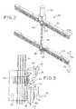
- FIG. 2is a view in perspective of a portion of the actuating mechanism illustrated in FIG. 1 , with the bearing blocks and cover eliminated to show the internal torque shaft and pinions;
- FIG. 3is a view taken substantially along line 3 - 3 of FIG. 2 ;
- FIG. 4is an exploded view in perspective of a recreational vehicle including a slide-out room, with actuating assemblies of the present invention shown exploded off of the sides of the slide-out room;
- FIG. 4Ais a partial perspective view of a slide-out room with the actuating assembly being applied to one side;
- FIG. 4Bis a view similar to FIG. 4A , but with the actuating assembly in place, prior to removal of the assembly straps;
- FIG. 4Cis an enlarged partial front elevational illustration of the slide-out room with the actuating assembly applied, with a portion of the assembly strap and the cover cut away to illustrate detail;
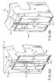
- FIG. 5is a view in perspective of a slide-out room with actuating assemblies made according to the present invention installed thereon;
- FIG. 6is a view similar to FIG. 5 , but illustrating the manner in which the slide-out room slides into the main living quarters and the manner in which the actuating assemblies are attached to the main living quarters;
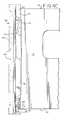
- FIG. 7is a view taken substantially along line 7 - 7 of FIG. 6 ;
- FIG. 8is a view taken substantially along line 8 - 8 of FIG. 7 ;
- FIG. 9is a view in perspective of a rack used in an alternate embodiment of the invention.
- FIG. 10is a schematic illustration of the control system used to control system used to control the actuating assemblies used in the present invention.
- FIG. 11is a detailed schematic of the control logic used in the control system illustrated in FIG. 10 .
- a mobile living quarterssuch as a recreational vehicle, is indicated generally at 10 , and includes a side wall 12 (the remaining side walls of the vehicle 10 not being shown).
- Side wall 12defines an aperture 14 through which a slide-out room generally indicated by the number 16 extends and retracts.
- Slide-out room 16includes a front wall 18 , two side walls 20 , 22 extending from the front wall 18 , a ceiling 24 and a floor 26 .
- Actuation assemblies 28 , 30are mounted on the side walls 20 , 22 respectively, the actuation assembly 30 being a mirror image of the actuation assembly 28 .
- each actuation assemblyincludes an upper rack 32 , a lower rack 34 , and a cover 36 defining a column which covers the mechanism that drives the rack 32 , 34 .
- rack and pinion actuatorsare shown, other equivalent interengaging, relatively movable members, such as welded chains and sprockets, a cog and stamping, timing belt and pulleys and other similar structures may be used; furthermore, although two rack and pinion assemblies are illustrated for each of the assemblies 28 , 30 , any number of assemblies may be used as necessary or convenient.
- Assembly straps 38 , 40are illustrated in FIGS. 1 and 4 ; these assembly straps are temporary to assure that the alignment of the racks 32 , 34 remain parallel to each other.
- Assembly strap 38includes a projecting flange 42 that projects beyond the racks 32 , 34 and is adapted to engage front wall 18 of the slide-out room 16 to thereby locate actuating assembly 28 laterally with respect to the slide-out room 16 .
- a bearing block covered by the cover of column 36engages the floor 26 of the slide-out room when the actuating assembly 28 is installed to thereby locate the actuating assembly vertically with respect to the slide-out room 16 .
- the actuating assemblies 28 , 30are fully assembled when they are manufactured and shipped to the assembly plant for attachment to the slide-out room 16 and to the main living quarters. Accordingly, no separate components are required, and assemblies 28 , 30 are inherently self-locating. Once the actuating assemblies 28 , 30 have been installed, the assembly straps 38 , 40 are removed and discarded.
- the column or cover 36includes a generally u-shaped portion 44 that extends around the actuating components for the racks 32 , 34 , as will hereinafter be described.
- a flange 46projects from the u-shaped portion 44 and is provided with apertures 48 , which receive fasteners 49 used to attach the actuating assemblies to the side wall 12 adjacent to the aperture 14 .
- the column 36trims up the edges of the aperture 14 and also carries a vertically extending bulb seal 50 , which seals the unit when the retractable room is fully retracted into the main living area.
- a splined torque shaft 52extends substantially vertically in the cover of column 36 and is rotatably supported by a lower bearing block 54 and an upper bearing block (not shown).
- the upper and lower bearing blockshave been omitted from FIG. 2 for clarity and are substantially identical, so that only lower bearing block 54 will be described in detail.
- Bearing block 54has been illustrated in phantom in FIGS. 3 and 7 for clarity.
- Torque shaft 52is defined by circumferentially spaced splines 56 , which are received in corresponding grooves in pinions 58 , 60 , which mesh with the gear racks 32 , 34 , respectively.
- Upper and lower gear racks 32 , 34are substantially identical, except that the lower gear rack 34 includes a flange 62 which projects therefrom and engages the lower side of the floor 26 of the slide-out room 16 to thereby locate the actuation assembly 28 vertically with respect thereto.
- a roller 64having a substantially v-shaped cross section to define bearing faces 66 , 68 , is rotatably mounted on a spindle 70 projecting from bearing block 54 .
- Rollers of other complex shapesmay be used instead of v-shaped rollers illustrated, it only being necessary that the rollers be shaped to control the relative positions of the rack and the roller, and to permit the slide-out room to move relative to the unit.
- the racks 32 , 34are each provided with a horizontally extending bearing surface defined by angled bearing faces 72 , 74 .
- the bearing faceswill, of course, be shaped complementary to the cross section of the roller.
- a hooked extensionextends from the bearing block 54 into a longitudinally extending groove 78 ( FIG. 2 ) of the rack 34 .
- Hooked extension 76is covered by a low friction, plastic (Delrin) shoe 80 which rides in the groove 78 as the slide-out room extends and retracts.
- the shoe 80 and groove 78maintain engagement of the roller 64 with the rack 34 and maintain engagement of the rack with the pinion.
- a bulb seal 50extends along u-shaped portion 44 of the column 36 .
- an extension 84 carried by the slide-out room 16engages bulb seal 50 , compressing the latter, to assure a weather-tight seal protecting the pinions, torque shafts, and motor from the environment.
- An electric motor 82is supported on the upper most end of the torque shaft 52 for rotating the latter.
- the motor 82is a bi-directional motor, and rotates the shaft in one direction to extend the slide-out room from the main living quarters, and in the opposite direction to retract the slide-out into the main living quarters.
- the actuation assembly 30 on the opposite side wall 22is a mirror image of the actuation assembly 28 .
- Another motor identical to the motor 83operates actuation assembly 30 .
- Both motorsare driven by a synchronizing drive control 90 , as illustrated in FIG. 10 and FIG. 11 , so that both the actuating assemblies extend and retract at substantially the same rate, as will hereinafter be described.
- a transverse shaftextending over the slide-out room and connected to both torque shafts 52 by a gear drive may be used with only one motor.
- synchronizing drive control 90includes a processor 92 , which transmits data to, and receives data from, a memory 94 .
- Input bus 96 for processor 92receives a voltage input from voltage sensor 98 , current sensor inputs 100 and 102 , which input signals measuring current draw of the corresponding motor, and tachometers or speed sensor inputs 104 , 106 , which are connected to speed sensors for each of the motors and which generate pulse trains that are proportional to the rotational speed of the motors.
- Other inputsinclude 108 and 110 , which transmit a signal from a wall switch within the unit which is operated when the user desires to extend or retract the slide-out room.
- Processor 92includes a pulse width modulator which generates pulse width modulated voltage signals which are transmitted to the motors through output bus 112 , as indicated at 114 and 116 .
- processor 92responds by starting the control routine, as indicated at 118 . Both motors are accelerated to their maximum speed, as indicated at 120 , it being noted that the maximum speed of the motors may be different (due, for example, to differences in weight carried on different sides of the slide-out room).
- a testis made, as indicated at 122 , to determine if either motor has reached the stall threshold. This is done by comparing the current draw of each motor, as sensed by sensor inputs 100 and 102 .
- the current draw of the motorsincreases substantially when the motor stalls out at the end of the stroke of the slide-out room (such as when it attains the fully extended or fully retracted position, or when the slide-out room encounters an obstruction requiring greatly increased power). If both motors are operating below the stall threshold, a check is made to determine if the motors are operating within a predetermined speed range of one another, as indicated at 124 . If the motors are operating outside of the speed range, the pulse width of the voltage signal to the faster motor is altered to slow the faster motor to within the speed range, as indicated at 126 .
- the stalled motoris dynamically braked, as indicated at 128 (by switching terminals of the motor together), and a stall timer is started.
- the current draw of the other motoris then tested to determine its stall threshold has been reached. If the stall threshold of the second motor has been reached, the second motor is braked (as indicated at 132 ), the values of the counts from the motor speed sensors stored in memory are reset to zero (as indicated at 134 ), and the routine is ended. If the test made at 130 indicates the second motor has not yet stalled out, a test is made at 136 to determine if the stall timer has timed out.
- the stall force timerassures that one motor will not be operated longer than a predetermined time period after the other motor has stalled, so that if the stalling is caused by one side of the slide-out room striking an obstruction, the motor actuating the other side will not operate indefinitely, or if the clearances across the slide-out room are sufficiently different that both sides of the slide-out room cannot be sealed, the system will not be operated indefinitely.
- the motors 82are caused to turn in a direction turning the pinions 58 , 60 to cause the racks, due to their engagement therewith, to be driven outwardly with respect to the main living quarters, thereby carrying the slide-out room with the rack.
- Rollers 64due to their engagement with the rack 34 , carry the weight of the slide-out room and maintain the floor 26 of the slide-out room raised above the floor of the main living quarters. Accordingly, damage to the floor of the main living quarters, common in the prior arts when slide-out rooms are extended or retracted, is avoided.
- actuating assemblies 28 , 30are shipped as a unit to the manufacturing plant, assembly and adjustment of separate components is not necessary.
- the slide-out room 16is retracted into the main living quarters by causing the motor 82 to turn in the reverse direction, thereby moving the racks 32 , 34 into the main living quarters, carrying the slide-out room 16 with them.
- the actuating assemblies 28 , 30are located vertically on their corresponding side walls 20 , 22 by engagement of the flange 62 with the floor 26 , and are located horizontally on their corresponding side walls 20 , 22 by the flange 42 of the assembly straps 38 , 40 .
- the clearance between the slide-out room and the side of the aperture 14is set by attachment of flange 62 to the side wall 12 . Since the bulb seal 50 is attached to the column 36 when the actuating assemblies 28 , 30 are manufactured and proper positioning of the actuating assemblies 28 , 30 on their corresponding side walls is assured, no adjustment of the slide-out room after installation on the unit is required or possible.
- a modified rack 86is provided with an upwardly inclining portion 88 .
- the operation of the unit equipped with the inclined rack 86is the same as in the preferred embodiment, except that when the pinion travels along the inclined section 88 the slide-out room is allowed to drop gradually, thereby bringing the floor of the slide-out room into registry with the floor of the main living quarters.
- the pinionsare allowed axial movement along the torque shaft, thereby permitting the pinions to remain in driving engagement with the rack teeth after the inclined section 88 is reached.
- the unit using the inclined rack 86is provided with a secondary roller having a v-shaped cross section (not shown). This secondary roller is much smaller than the roller 64 , and engages bearing surfaces 89 in the groove 91 , which extends longitudinally just above the tooth portion of the rack.
- the function of the secondary rolleris the same as the hooked extension 76 and shoe 80 .
Landscapes
- Engineering & Computer Science (AREA)
- Health & Medical Sciences (AREA)
- Public Health (AREA)
- Transportation (AREA)
- Mechanical Engineering (AREA)
- Power-Operated Mechanisms For Wings (AREA)
- Transmission Devices (AREA)
- Specific Sealing Or Ventilating Devices For Doors And Windows (AREA)
Abstract
Description
This application is a continuation of U.S. patent application Ser. No. 15/618,601, filed Jun. 9, 2017, which is a continuation of U.S. patent application Ser. No. 14/942,446, filed Nov. 16, 2015, which is a continuation of U.S. patent application Ser. No. 14/041,033, filed Sep. 30, 2013, now U.S. Pat. No. 9,193,291, which is a continuation of U.S. patent application Ser. No. 13/495,500, filed Jun. 13, 2012, now U.S. Pat. No. 8,581,540, issued on Nov. 12, 2013, which is a division of U.S. patent application Ser. No. 13/180,687, filed Jul. 12, 2011, now U.S. Pat. No. 8,317,250, issued on Nov. 27, 2012, which is a division of U.S. patent application Ser. No. 12/683,332, filed Jan. 6, 2010, now U.S. Pat. No. 8,016,343, issued on Sep. 13, 2011, which claims domestic priority based upon U.S. Provisional Patent Application No. 61/205,551, filed Jan. 21, 2009, the disclosures of which are hereby incorporated by reference in their entireties.
This invention relates to a slide-out or retractable room for mobile living quarters, such as a recreation vehicle.
Recreational vehicles, such as motor homes, fifth-wheel trailers, and travel trailers may be provided with a retractable or slide-out room for increasing the living space of the vehicle. The retractable or slide-out room is extended for use when the vehicle is parked and is retracted into the main living area of the vehicle when the vehicle is to be moved. Existing retractable or slide-out rooms can be time-consuming and difficult to install. Frequently, the operating mechanisms consist of many separate components that must be individually installed, connected and adjusted by highly-trained employees when the unit is assembled. After the vehicle is put into service, adjustments by the vehicle owner are often necessary. Furthermore, existing slide-out rooms require substantial space for mounting large electrical motors and hydraulic units that require the construction of expensive covers and thus reduce the overall space inside the vehicle. Such slide-out or retractable rooms are generally moved in and out of the vehicle across the floor of the main living area. Because the slide-out or retractable room is exposed to weather when extended, extension and retraction of the slide-out room causes staining and wear on the interior floor of the vehicle.
Generally, the physical size of the operating mechanism or slide-out room is large and bulky and somehow has to be hidden. Concealing the operating mechanism requires space either inside the vehicle, which lessens the living space, or under the vehicle, which lessen room for the mechanical systems such as storage tanks and axles. The object of any slide-out room is to add space, so a need exists for a slide mechanism that requires no interior or exterior space.
Generally, existing mechanisms for extending and retracting slide-out rooms employ powerful hydraulic or eletro-mechanical systems that have a fixed amount of working stroke. When actuated, these powerful devices will push or pull the slide room until they run out of useable stroke. When obstructions, such as trees on the exterior or furniture and suitcases on the interior, are encountered before the wholly extended or wholly retracted position is attained, the actuation mechanism has more then enough power to overcome the obstruction and keep going. This can destroy the slide-out room, which is generally made from light weight wood or aluminum tube. Sadly, sometimes human beings are encountered, often resulting in injury or death. Therefore, it is desirable that obstructions be sensed and the actuation mechanism stopped,
Tolerances needed to construct slide-out rooms are large. Therefore, the side walls of the same slide-out room rarely have the same dimensions. When one side wall is deeper than the other side wall, only the shorter side wall can be adjusted to properly seal against the weather. An example is a slideroom that has one side wall built incrementally longer than the other side wall. With a fixed stroke equal to the length of the shorter side wall, the longer side is unable to attain full stroke and properly seal. This permits moisture to enter the unit and cause extensive damage. Therefore, a need exists for a slide room mechanism that can independently sense and automatically adjust stroke to a sealed position on each side of the slide room.
All known prior art for slide room mechanisms attach the actuating mechanism to the unit. Sometimes the mechanism is mounted to the floor of the unit, or to the side wall, chassis or frame of the unit. After the actuating mechanism is mounted on the unit, the slide-out room is attached. Due to natural manufacturing tolerances, the opening to accept the slide-out room typically varies from unit to unit in both height and width, while the slide-out room itself also varies in height and width. However, the seal used to keep weather out of the unit is manufactured to a set dimension. Numerous adjustments up and down and left and right are required to center the slide-out room to the opening in the unit in order to provide a weather-tight seal when the room is extended and retracted. As the unit is used, normal road vibrations tend to cause the slide-out room to come out of adjustment, allowing moisture to enter the interior of the vehicle causing extensive damage. Therefore, a need exists for a slide room mechanism that requires no mechanical adjustment, both at installation and as it is used.
According to the present invention, actuating mechanisms are installed on opposite side walls of the slide-out room and the adjoining portions of the wall of the main living area through which the slide-out room extends and retracts. Each of the actuating assemblies include a pair of pinion gears mounted on a rotatable torque shaft, which are supported for rotation on the main living quarters adjacent to the aperture in the wall of the main living quarters through which the slide-out room extends and retracts. The two pinion gears rotate with a common shaft, and are meshed with the teeth of corresponding gear racks which are mounted on the adjacent side wall of the slide-out room. Rollers engage corresponding bearing surfaces defined on the racks to support the slide-out room as it extends and retracts and also to assure that the pinions remain meshed with the racks. In an optional embodiment of the invention, racks are provided with an inclined section, which permits the room to drop as it approaches the extended position to bring the floor of the slide-out room flush with the floor of the main living quarters, thereby eliminating the unsightly and inconvenient step-up between the slide-out room and the main living quarters.
Referring now to the drawings, a mobile living quarters, such as a recreational vehicle, is indicated generally at10, and includes a side wall12 (the remaining side walls of thevehicle 10 not being shown).Side wall 12 defines anaperture 14 through which a slide-out room generally indicated by thenumber 16 extends and retracts. Slide-out room 16 includes afront wall 18, twoside walls front wall 18, aceiling 24 and afloor 26.
The column or cover36 includes a generallyu-shaped portion 44 that extends around the actuating components for theracks flange 46 projects from theu-shaped portion 44 and is provided withapertures 48, which receivefasteners 49 used to attach the actuating assemblies to theside wall 12 adjacent to theaperture 14. In addition to concealing and protecting the actuation components, thecolumn 36 trims up the edges of theaperture 14 and also carries a vertically extendingbulb seal 50, which seals the unit when the retractable room is fully retracted into the main living area.
Asplined torque shaft 52 extends substantially vertically in the cover ofcolumn 36 and is rotatably supported by alower bearing block 54 and an upper bearing block (not shown). The upper and lower bearing blocks have been omitted fromFIG. 2 for clarity and are substantially identical, so that onlylower bearing block 54 will be described in detail.Bearing block 54 has been illustrated in phantom inFIGS. 3 and 7 for clarity.Torque shaft 52 is defined by circumferentially spacedsplines 56, which are received in corresponding grooves inpinions lower gear rack 34 includes aflange 62 which projects therefrom and engages the lower side of thefloor 26 of the slide-out room 16 to thereby locate theactuation assembly 28 vertically with respect thereto.
Aroller 64, having a substantially v-shaped cross section to define bearing faces66,68, is rotatably mounted on aspindle 70 projecting from bearingblock 54. Rollers of other complex shapes may be used instead of v-shaped rollers illustrated, it only being necessary that the rollers be shaped to control the relative positions of the rack and the roller, and to permit the slide-out room to move relative to the unit. Theracks block 54 into a longitudinally extending groove78 (FIG. 2 ) of therack 34.Hooked extension 76 is covered by a low friction, plastic (Delrin)shoe 80 which rides in thegroove 78 as the slide-out room extends and retracts. Theshoe 80 andgroove 78 maintain engagement of theroller 64 with therack 34 and maintain engagement of the rack with the pinion. As described above, abulb seal 50 extends alongu-shaped portion 44 of thecolumn 36. As can be seen inFIG. 8 , when the slide-out room 16 is in the fully retracted position, anextension 84 carried by the slide-out room 16 engagesbulb seal 50, compressing the latter, to assure a weather-tight seal protecting the pinions, torque shafts, and motor from the environment.
Anelectric motor 82 is supported on the upper most end of thetorque shaft 52 for rotating the latter. Themotor 82 is a bi-directional motor, and rotates the shaft in one direction to extend the slide-out room from the main living quarters, and in the opposite direction to retract the slide-out into the main living quarters. Theactuation assembly 30 on theopposite side wall 22 is a mirror image of theactuation assembly 28. Another motor identical to the motor83 operatesactuation assembly 30. Both motors are driven by a synchronizingdrive control 90, as illustrated inFIG. 10 andFIG. 11 , so that both the actuating assemblies extend and retract at substantially the same rate, as will hereinafter be described. Alternatively, a transverse shaft extending over the slide-out room and connected to bothtorque shafts 52 by a gear drive may be used with only one motor.
Referring now toFIG. 10 , synchronizingdrive control 90 includes aprocessor 92, which transmits data to, and receives data from, amemory 94.Input bus 96 forprocessor 92 receives a voltage input fromvoltage sensor 98,current sensor inputs speed sensor inputs 104,106, which are connected to speed sensors for each of the motors and which generate pulse trains that are proportional to the rotational speed of the motors. Other inputs include108 and110, which transmit a signal from a wall switch within the unit which is operated when the user desires to extend or retract the slide-out room. The effect of theinputs system 90 is otherwise the same if the slide-out room is either extended or retracted.Processor 92 includes a pulse width modulator which generates pulse width modulated voltage signals which are transmitted to the motors throughoutput bus 112, as indicated at114 and116.
Referring now toFIG. 11 , when the user operates the wall switch to either extend or retract the slide-out room,processor 92 responds by starting the control routine, as indicated at118. Both motors are accelerated to their maximum speed, as indicated at120, it being noted that the maximum speed of the motors may be different (due, for example, to differences in weight carried on different sides of the slide-out room). A test is made, as indicated at122, to determine if either motor has reached the stall threshold. This is done by comparing the current draw of each motor, as sensed bysensor inputs
If the test at122 indicates that one of the motors has reached the stall threshold, the stalled motor is dynamically braked, as indicated at128 (by switching terminals of the motor together), and a stall timer is started. As indicated at130, the current draw of the other motor is then tested to determine its stall threshold has been reached. If the stall threshold of the second motor has been reached, the second motor is braked (as indicated at132), the values of the counts from the motor speed sensors stored in memory are reset to zero (as indicated at134), and the routine is ended. If the test made at130 indicates the second motor has not yet stalled out, a test is made at136 to determine if the stall timer has timed out. If the stall timer has timed out, the other motor is stopped (as indicated at138), whereupon the routine is ended. By continuing to operate the motor not reaching the stall threshold after the first motor reaching the stall threshold has been stopped, both sides of the slide-out room are independently brought into engagement with their corresponding bulb seals50, thus assuring sealing completely around the slide-out room. The stall force timer assures that one motor will not be operated longer than a predetermined time period after the other motor has stalled, so that if the stalling is caused by one side of the slide-out room striking an obstruction, the motor actuating the other side will not operate indefinitely, or if the clearances across the slide-out room are sufficiently different that both sides of the slide-out room cannot be sealed, the system will not be operated indefinitely.
In operation, when the user desires to extend the slide-out room 16, themotors 82 are caused to turn in a direction turning thepinions Rollers 64, due to their engagement with therack 34, carry the weight of the slide-out room and maintain thefloor 26 of the slide-out room raised above the floor of the main living quarters. Accordingly, damage to the floor of the main living quarters, common in the prior arts when slide-out rooms are extended or retracted, is avoided. Since, as described above,actuating assemblies out room 16 is retracted into the main living quarters by causing themotor 82 to turn in the reverse direction, thereby moving theracks out room 16 with them.
As discussed above, prior art slide-out rooms require multiple adjustments to center the slide-out room in the opening in the unit in order to provide a weather-tight seal when the room is extended and retracted, and require periodic adjustments to re-center the slide-out room to compensate for normal road vibrations. In the present invention, theactuating assemblies corresponding side walls flange 62 with thefloor 26, and are located horizontally on theircorresponding side walls flange 42 of the assembly straps38,40. The clearance between the slide-out room and the side of theaperture 14 is set by attachment offlange 62 to theside wall 12. Since thebulb seal 50 is attached to thecolumn 36 when theactuating assemblies actuating assemblies
Slide-out rooms tend to tip downward relative to the unit when extended, and this tipping must be resisted, requiring heavier and more powerful actuators than would otherwise be necessary. In the present invention, tipping forces are transmitted throughupper rack 32 andpinion 60 to apply a twisting force to thetorque shaft 52, which is resisted by the torsional stiffness of thetorque shaft 52. The twisting forces are transmitted through thetorque shaft 52 to thelower pinion 58 and thelower rack 34, to thereby apply a countervailing force to the lower portion of the slide-out room, thereby tending to right the slide-out room. Accordingly, the power required of themotor 82 remains relatively small compared to prior art actuating mechanisms.
Referring now toFIG. 9 , a modifiedrack 86 is provided with an upwardly incliningportion 88. The operation of the unit equipped with theinclined rack 86 is the same as in the preferred embodiment, except that when the pinion travels along theinclined section 88 the slide-out room is allowed to drop gradually, thereby bringing the floor of the slide-out room into registry with the floor of the main living quarters. The pinions are allowed axial movement along the torque shaft, thereby permitting the pinions to remain in driving engagement with the rack teeth after theinclined section 88 is reached. Instead of the hookedextension 76 andshoe 80, the unit using theinclined rack 86 is provided with a secondary roller having a v-shaped cross section (not shown). This secondary roller is much smaller than theroller 64, and engages bearingsurfaces 89 in thegroove 91, which extends longitudinally just above the tooth portion of the rack. The function of the secondary roller is the same as the hookedextension 76 andshoe 80.
This invention is not limited to the details above, but may be modified within the scope of the following claims.
Claims (21)
1. An actuating assembly for extending and retracting through an aperture in a side wall of a mobile living quarters a slide out room having first and second opposing side walls and a floor, the actuating assembly comprising:
an upper gear rack comprising teeth, the upper gear rack configured for mounting on an upper portion of the first side wall of the slide out room such that the teeth face outwardly from the first side wall of the slide out room, the upper gear rack further comprising a longitudinally extending groove;
a lower gear rack comprising teeth, the lower gear rack configured for mounting on a lower portion of the first side wall of the slide out room such that the teeth face outwardly from the first side wall of the slide out room, the lower gear rack further comprising a longitudinally extending groove;
a drive mechanism configured for mounting to the side wall of the mobile living quarters adjacent to the aperture in the side wall of the mobile living quarters and adjacent the first side wall of the slide out room, the drive mechanism comprising:
a column configured for attachment to the side wall of the mobile living quarters;
an upper bearing block disposed in an upper portion of the column;
a first hooked extension extending from the upper bearing block into the longitudinally extending groove of the upper gear rack;
a lower bearing block disposed in a lower portion of the column;
a second hooked extension extending from the lower bearing block into the longitudinally extending groove of the lower gear rack;
a torque shaft having a longitudinal axis, the torque shaft rotatably supported by the upper bearing block and the lower bearing block;
an upper pinion gear engaged with the torque shaft and the upper gear rack;
a lower pinion gear engaged with the torque shaft and the lower gear rack; and
an electric motor configured to rotate the torque shaft, the motor disposed in the column;
wherein the torque shaft, the upper pinion gear, and the lower pinion gear are allowed to float on an axis perpendicular to the torque shaft axis.
2. The actuating assembly ofclaim 1 further comprising:
a first assembly strap connected to a first end of the upper gear rack and a first end of the lower gear rack; and
a second assembly strap connected to a second end of the upper gear rack and a second end of the lower gear rack;
wherein the upper gear rack is parallel to the lower gear rack.
3. The actuating assembly ofclaim 2 wherein one of the first assembly strap and the second assembly strap includes a projecting flange configured to locate the actuating assembly laterally with respect to the slide out room.
4. The actuating assembly ofclaim 1 , the lower gear rack further comprising a flange projecting therefrom for engagement with a lower side of the floor of the slide out room.
5. The actuating assembly ofclaim 1 , wherein the column comprises a flange configured to trim up edges of the aperture in the side wall of the mobile living quarters.
6. The actuating assembly ofclaim 1 , wherein at least one of the upper bearing block and the lower bearing block rests on keys restricting movement of the at least one of the upper bearing block and the lower bearing block parallel to the torque shaft axis and allowing movement of the at least one of the upper bearing block and the lower bearing block perpendicular to the torque shaft axis.
7. An actuating assembly for extending and retracting through an aperture in a side wall of a mobile living quarters a slide out room having first and second opposing side walls and a floor, the actuating assembly comprising:
an upper gear rack comprising teeth, the upper gear rack configured for mounting on an upper portion of the first side wall of the slide out room such that the teeth face outwardly from the first side wall of the slide out room, the upper gear rack further comprising a longitudinally extending groove;
a lower gear rack comprising teeth, the lower gear rack configured for mounting on a lower portion of the first side wall of the slide out room such that the teeth face outwardly from the first side wall of the slide out room, the lower gear rack further comprising a longitudinally extending groove;
a drive mechanism configured for mounting to the side wall of the mobile living quarters adjacent to the aperture in the side wall of the mobile living quarters and adjacent the first side wall of the slide out room, the drive mechanism comprising:
a column configured for attachment to the side wall of the mobile living quarters;
an upper bearing block disposed in an upper portion of the column;
a first hooked extension extending from the upper bearing block into the longitudinally extending groove of the upper gear rack;
a lower bearing block disposed in a lower portion of the column;
a second hooked extension extending from the lower bearing block into the longitudinally extending groove of the lower gear rack;
a torque shaft having a longitudinal axis, the torque shaft rotatably supported by the upper bearing block and the lower bearing block;
an upper pinion gear engaged with the upper gear rack;
a lower pinion gear engaged with the torque shaft and the lower gear rack; and
a motor engaged with the upper pinion gear, the motor disposed in the column;
wherein the torque shaft, the upper pinion gear, and the lower pinion gear are allowed to float on an axis perpendicular to the torque shaft axis.
8. The actuating assembly ofclaim 7 wherein rotation of the motor results in rotation of the upper pinion gear and the lower pinion gear.
9. The actuating assembly ofclaim 7 further comprising:
a first assembly strap connected to a first end of the upper gear rack and a first end of the lower gear rack; and
a second assembly strap connected to a second end of the upper gear rack and a second end of the lower gear rack;
wherein the upper gear rack is parallel to the lower gear rack.
10. The actuating assembly ofclaim 7 wherein one of the first assembly strap and the second assembly strap includes a projecting flange configured to locate the actuating assembly laterally with respect to the slide out room.
11. The actuating assembly ofclaim 7 , the lower gear rack further comprising a flange projecting therefrom for engagement with a lower side of the floor of the slide out room.
12. The actuating assembly ofclaim 7 , wherein the column comprises a flange configured to trim up edges of the aperture in the side wall of the mobile living quarters.
13. The actuating assembly ofclaim 7 , wherein at least one of the upper bearing block and the lower bearing block rests on keys restricting movement of the at least one of the upper bearing block and the lower bearing block parallel to the torque shaft axis and allowing movement of the at least one of the upper bearing block and the lower bearing block perpendicular to the torque shaft axis.
14. An actuating assembly for extending and retracting through an aperture in a side wall of a mobile living quarters a slide out room having first and second opposing side walls and a floor, the actuating assembly comprising:
an upper gear rack comprising teeth, the upper gear rack configured for mounting on an upper portion of the first side wall of the slide out room such that the teeth face outwardly from the first side wall of the slide out room, the upper gear rack further comprising a longitudinally extending groove;
a lower gear rack comprising teeth, the lower gear rack configured for mounting on a lower portion of the first side wall of the slide out room such that the teeth face outwardly from the first side wall of the slide out room, the lower gear rack further comprising a longitudinally extending groove;
a drive mechanism configured for mounting to the side wall of the mobile living quarters adjacent to the aperture in the side wall of the mobile living quarters and adjacent the first side wall of the slide out room, the drive mechanism comprising:
a column configured for attachment to the side wall of the mobile living quarters;
an upper bearing block disposed in an upper portion of the column;
a first hooked extension extending from the upper bearing block, the first hooked extension configured for engagement with the longitudinally extending groove of the upper gear rack;
a lower bearing block disposed in a lower portion of the column;
a second hooked extension extending from the lower bearing block, the second hooked extension configured for engagement with the longitudinally extending groove of the lower gear rack;
a torque shaft having a longitudinal axis, the torque shaft rotatably supported by the upper bearing block and the lower bearing block;
an upper pinion gear engaged with the torque shaft and the upper gear rack; and
a lower pinion gear engaged with the torque shaft and the lower gear rack;
wherein rotation of the upper and lower pinion gears drives the upper and lower gear racks, and
wherein the torque shaft, the upper pinion gear, and the lower pinion gear are allowed to float on an axis perpendicular to the torque shaft axis.
15. The actuating assembly ofclaim 14 further comprising:
a first assembly strap connected to a first end of the upper gear rack and a first end of the lower gear rack; and
a second assembly strap connected to a second end of the upper gear rack and a second end of the lower gear rack;
wherein the upper gear rack is parallel to the lower gear rack.
16. The actuating assembly ofclaim 14 wherein one of the first assembly strap and the second assembly strap is configured to locate the actuating assembly laterally with respect to the slide out room.
17. The actuating assembly ofclaim 14 wherein one of the first assembly strap and the second assembly strap includes a projecting flange configured to locate the actuating assembly laterally with respect to the slide out room.
18. The actuating assembly ofclaim 14 , the lower gear rack further comprising a flange projecting therefrom for engagement with a lower side of the floor of the slide out room.
19. The actuating assembly ofclaim 14 , wherein the column comprises a flange configured to trim up edges of the aperture in the side wall of the mobile living quarters.
20. The actuating assembly ofclaim 14 , wherein at least one of the upper bearing block and the lower bearing block rests on keys restricting movement of the at least one of the upper bearing block and the lower bearing block parallel to the torque shaft axis and allowing movement of the at least one of the upper bearing block and the lower bearing block perpendicular to the torque shaft axis.
21. The actuating assembly ofclaim 14 further comprising a motor configured to drive said upper and lower pinion gears, the motor disposed in the column.
Priority Applications (3)
| Application Number | Priority Date | Filing Date | Title |
|---|---|---|---|
| US16/152,843US10471878B2 (en) | 2009-01-21 | 2018-10-05 | Retractable room actuation assembly for recreational vehicle |
| US16/659,910US11059413B2 (en) | 2009-01-21 | 2019-10-22 | Retractable room actuation assembly for recreational vehicle |
| US17/341,608US20210291717A1 (en) | 2009-01-21 | 2021-06-08 | Retractable room actuation assembly for recreational vehicle |
Applications Claiming Priority (8)
| Application Number | Priority Date | Filing Date | Title |
|---|---|---|---|
| US20555109P | 2009-01-21 | 2009-01-21 | |
| US12/683,332US8016343B2 (en) | 2009-01-21 | 2010-01-06 | Retractable room actuation assembly for recreational vehicle |
| US13/180,687US8317250B2 (en) | 2009-01-21 | 2011-07-12 | Method for installing actuation mechanism for extending and retracting retractable room for recreational vehicle |
| US13/495,500US8581540B2 (en) | 2009-01-21 | 2012-06-13 | Method for installing actuation mechanism for extending and retracting retractable room for recreational vehicle |
| US14/041,033US9193291B2 (en) | 2009-01-21 | 2013-09-30 | Retractable room actuation assembly for recreational vehicle |
| US14/942,446US9694733B2 (en) | 2009-01-21 | 2015-11-16 | Retractable room actuation assembly for recreational vehicle |
| US15/618,601US10093219B2 (en) | 2009-01-21 | 2017-06-09 | Retractable room actuation assembly for recreational vehicle |
| US16/152,843US10471878B2 (en) | 2009-01-21 | 2018-10-05 | Retractable room actuation assembly for recreational vehicle |
Related Parent Applications (1)
| Application Number | Title | Priority Date | Filing Date |
|---|---|---|---|
| US15/618,601ContinuationUS10093219B2 (en) | 2009-01-21 | 2017-06-09 | Retractable room actuation assembly for recreational vehicle |
Related Child Applications (1)
| Application Number | Title | Priority Date | Filing Date |
|---|---|---|---|
| US16/659,910ContinuationUS11059413B2 (en) | 2009-01-21 | 2019-10-22 | Retractable room actuation assembly for recreational vehicle |
Publications (2)
| Publication Number | Publication Date |
|---|---|
| US20190031077A1 US20190031077A1 (en) | 2019-01-31 |
| US10471878B2true US10471878B2 (en) | 2019-11-12 |
Family
ID=43526286
Family Applications (13)
| Application Number | Title | Priority Date | Filing Date |
|---|---|---|---|
| US12/683,332CeasedUS8016343B2 (en) | 2009-01-21 | 2010-01-06 | Retractable room actuation assembly for recreational vehicle |
| US13/180,654ActiveUS8240744B2 (en) | 2009-01-21 | 2011-07-12 | Retractable room actuation assembly for recreational vehicle having engagement mechanism for maintaining constant distance between drive members and engagement members |
| US13/180,687Expired - Fee RelatedUS8317250B2 (en) | 2009-01-21 | 2011-07-12 | Method for installing actuation mechanism for extending and retracting retractable room for recreational vehicle |
| US13/180,671ActiveUS8235455B2 (en) | 2009-01-21 | 2011-07-12 | Retractable room actuation assembly for recreational vehicle having engagement means for maintaining constant distance between drive members and engagement members |
| US13/495,500Active2030-01-15US8581540B2 (en) | 2009-01-21 | 2012-06-13 | Method for installing actuation mechanism for extending and retracting retractable room for recreational vehicle |
| US13/537,189ActiveUSRE44002E1 (en) | 2009-01-21 | 2012-06-29 | Retractable room actuation assembly for recreational vehicle |
| US14/041,033Active2030-05-07US9193291B2 (en) | 2009-01-21 | 2013-09-30 | Retractable room actuation assembly for recreational vehicle |
| US14/507,153ActiveUS9007012B2 (en) | 2009-01-21 | 2014-10-06 | Retractable room actuation assembly for recreational vehicle |
| US14/942,446ActiveUS9694733B2 (en) | 2009-01-21 | 2015-11-16 | Retractable room actuation assembly for recreational vehicle |
| US15/618,601ActiveUS10093219B2 (en) | 2009-01-21 | 2017-06-09 | Retractable room actuation assembly for recreational vehicle |
| US16/152,843ActiveUS10471878B2 (en) | 2009-01-21 | 2018-10-05 | Retractable room actuation assembly for recreational vehicle |
| US16/659,910ActiveUS11059413B2 (en) | 2009-01-21 | 2019-10-22 | Retractable room actuation assembly for recreational vehicle |
| US17/341,608AbandonedUS20210291717A1 (en) | 2009-01-21 | 2021-06-08 | Retractable room actuation assembly for recreational vehicle |
Family Applications Before (10)
| Application Number | Title | Priority Date | Filing Date |
|---|---|---|---|
| US12/683,332CeasedUS8016343B2 (en) | 2009-01-21 | 2010-01-06 | Retractable room actuation assembly for recreational vehicle |
| US13/180,654ActiveUS8240744B2 (en) | 2009-01-21 | 2011-07-12 | Retractable room actuation assembly for recreational vehicle having engagement mechanism for maintaining constant distance between drive members and engagement members |
| US13/180,687Expired - Fee RelatedUS8317250B2 (en) | 2009-01-21 | 2011-07-12 | Method for installing actuation mechanism for extending and retracting retractable room for recreational vehicle |
| US13/180,671ActiveUS8235455B2 (en) | 2009-01-21 | 2011-07-12 | Retractable room actuation assembly for recreational vehicle having engagement means for maintaining constant distance between drive members and engagement members |
| US13/495,500Active2030-01-15US8581540B2 (en) | 2009-01-21 | 2012-06-13 | Method for installing actuation mechanism for extending and retracting retractable room for recreational vehicle |
| US13/537,189ActiveUSRE44002E1 (en) | 2009-01-21 | 2012-06-29 | Retractable room actuation assembly for recreational vehicle |
| US14/041,033Active2030-05-07US9193291B2 (en) | 2009-01-21 | 2013-09-30 | Retractable room actuation assembly for recreational vehicle |
| US14/507,153ActiveUS9007012B2 (en) | 2009-01-21 | 2014-10-06 | Retractable room actuation assembly for recreational vehicle |
| US14/942,446ActiveUS9694733B2 (en) | 2009-01-21 | 2015-11-16 | Retractable room actuation assembly for recreational vehicle |
| US15/618,601ActiveUS10093219B2 (en) | 2009-01-21 | 2017-06-09 | Retractable room actuation assembly for recreational vehicle |
Family Applications After (2)
| Application Number | Title | Priority Date | Filing Date |
|---|---|---|---|
| US16/659,910ActiveUS11059413B2 (en) | 2009-01-21 | 2019-10-22 | Retractable room actuation assembly for recreational vehicle |
| US17/341,608AbandonedUS20210291717A1 (en) | 2009-01-21 | 2021-06-08 | Retractable room actuation assembly for recreational vehicle |
Country Status (1)
| Country | Link |
|---|---|
| US (13) | US8016343B2 (en) |
Cited By (3)
| Publication number | Priority date | Publication date | Assignee | Title |
|---|---|---|---|---|
| US11130535B1 (en)* | 2020-07-16 | 2021-09-28 | Yang and Cohen Enterprises, Inc. | User configurable trailer |
| TWI819856B (en)* | 2022-10-18 | 2023-10-21 | 洪紳勝 | Camping vehicle with expandable cabin |
| US12405619B2 (en) | 2021-08-27 | 2025-09-02 | Valid Manufacturing Ltd | Method and system for dynamically controlling a slide-out assembly |
Families Citing this family (43)
| Publication number | Priority date | Publication date | Assignee | Title |
|---|---|---|---|---|
| US9408607B2 (en) | 2009-07-02 | 2016-08-09 | Edwards Lifesciences Cardiaq Llc | Surgical implant devices and methods for their manufacture and use |
| US20100066025A1 (en)* | 2008-09-18 | 2010-03-18 | Kreil Craig J | Vehicle Seal With Sensor Feedback |
| US20120261944A1 (en)* | 2008-09-18 | 2012-10-18 | Kreil Craig J | Vehicle Seal With Sensor Feedback |
| US8016343B2 (en) | 2009-01-21 | 2011-09-13 | Lippert Components Manufacturing, Inc. | Retractable room actuation assembly for recreational vehicle |
| US20100219652A1 (en)* | 2009-02-27 | 2010-09-02 | Reske Craig J | Slide-Out Mechanism With Adhesive Connections |
| US8266843B2 (en)* | 2009-12-30 | 2012-09-18 | R-N-R International, Inc. | Slide-out room actuator |
| AU2011205108A1 (en)* | 2010-08-06 | 2012-02-23 | Actuant Corporation | Wall movement synchronization slide-out room system and method |
| US8925990B2 (en) | 2011-10-26 | 2015-01-06 | Lippert Components Manufacturing, Inc. | Slide-out room system having wall-mounted drive mechanisms with brake |
| US8991890B2 (en) | 2011-10-26 | 2015-03-31 | Lippert Components Manufacturing, Inc. | Slide-out room system having wall-mounted drive mechanisms |
| US20130119694A1 (en)* | 2011-11-11 | 2013-05-16 | Norco Industries, Inc. | Drive assembly for expandable enclosure |
| US8967694B2 (en) | 2011-11-11 | 2015-03-03 | Norco Industries, Inc. | Slide out drive assembly for enclosure |
| US8701351B2 (en) | 2012-04-13 | 2014-04-22 | Trim-Lok, Inc. | Flexible seal for recreational vehicles |
| US8875443B2 (en) | 2012-04-13 | 2014-11-04 | TrimLok, Inc. | Flexible seal for recreational vehicles |
| US8910422B2 (en) | 2012-04-13 | 2014-12-16 | Trim-Lok, Inc. | Flexible seal for recreational vehicles |
| US8985662B2 (en)* | 2012-04-30 | 2015-03-24 | TrimLok, Inc. | Fascia board for RV |
| US11072272B2 (en)* | 2012-07-05 | 2021-07-27 | David Fought | Movable wall structure for a travel trailer |
| US9221378B2 (en) | 2012-11-20 | 2015-12-29 | AL-KO Kober A.G. | Slide-out room mechanism for a vehicle |
| CN103010080B (en)* | 2012-12-24 | 2015-04-15 | 胡明华 | Hydraulic driven synchronizing mechanism of full-automatic multifunctional retractable motor home |
| US9050923B1 (en)* | 2013-03-14 | 2015-06-09 | Norco Industries, Inc. | Slidable room assembly |
| ES2784678T3 (en)* | 2013-08-06 | 2020-09-29 | Lippert Components Mfg Inc | Manual control for sliding cabin system that has a wall-mounted drive mechanism |
| US9033390B1 (en)* | 2014-04-01 | 2015-05-19 | Lifetime Industries, Inc. | Edge seal with sidewall seal |
| US9738209B2 (en)* | 2015-03-31 | 2017-08-22 | Opp Xl B.V. | Slide-out room and operating mechanism and components thereof |
| US9738208B2 (en)* | 2015-03-31 | 2017-08-22 | Opp Xl B.V. | Slide-out for recreational vehicles |
| US9944215B2 (en) | 2015-03-31 | 2018-04-17 | Opp Xl B.V. | Slide-out room and operating mechanism and components thereof |
| WO2017035068A1 (en) | 2015-08-25 | 2017-03-02 | Lippert Components, Inc. | Slide-out room for van |
| ITUB20155826A1 (en)* | 2015-11-23 | 2017-05-23 | Davide Nardini | variable configuration structure for recreational vehicle |
| DE102015225269B4 (en)* | 2015-12-15 | 2021-11-25 | Protec Gmbh & Co. Kg | Motorhome |
| US20180051746A1 (en)* | 2016-08-17 | 2018-02-22 | Lippert Components, Inc. | Operating mechanism for movable compartment |
| JP6550112B2 (en)* | 2016-10-17 | 2019-07-24 | 華碩電腦股▲ふん▼有限公司 | Method and apparatus for processing DRX (intermittent reception) operation in a wireless communication system |
| US11639129B2 (en) | 2017-09-22 | 2023-05-02 | Norco Industries, Inc. | Slidable room assemblies |
| US11034279B2 (en) | 2018-04-09 | 2021-06-15 | Lippert Components, Inc. | Slide out ramp |
| CN108857310B (en)* | 2018-07-18 | 2023-11-21 | 湖南进军隧道智能装备有限公司 | Mobile installation vehicle for excavation stand |
| DE102019009268B3 (en) | 2019-01-08 | 2022-10-13 | Jörg Kortmann | Equipment system for equipping a motor vehicle |
| US10927929B2 (en) | 2019-02-05 | 2021-02-23 | David H. Vroom | Preventing torque-caused impair of a sliding support mechanism |
| US10480627B1 (en) | 2019-02-05 | 2019-11-19 | David H. Vroom | Sliding support mechanism with improved reliability and serviceability |
| EP3715176B1 (en) | 2019-03-26 | 2021-06-30 | LCI Italy S.r.l. | Drive unit for a slide-out room |
| CN111775818A (en)* | 2019-04-03 | 2020-10-16 | 利珀特组件公司 | Slide-out mechanism with fixed spindle drive |
| IT201900007033A1 (en) | 2019-05-20 | 2020-11-20 | Lci Italy Srl | SLIDING MECHANISM OF A REMOVABLE ROOM WITH CABLE OPERATION |
| IT201900007030A1 (en)* | 2019-05-20 | 2020-11-20 | Lci Italy Srl | SLIDING MECHANISM OF A REMOVABLE ROOM WITH PINION AND RACK OPERATION |
| US11287044B1 (en) | 2021-06-11 | 2022-03-29 | Trim-Lok, Inc. | Slide seal |
| US11318827B1 (en) | 2021-07-15 | 2022-05-03 | Trim-Lok, Inc. | Bottom pan seal system |
| CN115041440B (en)* | 2022-05-24 | 2024-01-19 | 国网山东省电力公司菏泽供电公司 | A sign for vehicle management |
| KR102681238B1 (en)* | 2022-06-27 | 2024-07-04 | 주식회사 프로스코 | Camping car with a pull-out camping house |
Citations (154)
| Publication number | Priority date | Publication date | Assignee | Title |
|---|---|---|---|---|
| US1279819A (en) | 1917-01-17 | 1918-09-24 | William E Zingsheim | Sleeping-porch. |
| US1521635A (en) | 1924-02-07 | 1925-01-06 | Samuel L Lewis | Portable unit building |
| US2136130A (en) | 1938-01-28 | 1938-11-08 | Gorlenko Louis | Vehicle body |
| US2561921A (en) | 1947-06-28 | 1951-07-24 | Guillot Lucien Edouard | Trailer |
| US2704233A (en) | 1953-06-19 | 1955-03-15 | Gen Motors Corp | Wheel bearing adjustment |
| US2744781A (en) | 1953-03-09 | 1956-05-08 | Trailmobile Inc | Expansible vehicle body |
| US2813747A (en) | 1956-03-16 | 1957-11-19 | Jr Lester T Rice | Expansible house trailer |
| US2877509A (en) | 1957-10-11 | 1959-03-17 | David W Klibanow | Trailer constructions |
| DE1095137B (en) | 1958-05-31 | 1960-12-15 | Herbert Vidal & Co Karosserie | Motor vehicle or trailer body with extendable and retractable side parts |
| US2965412A (en) | 1957-03-04 | 1960-12-20 | Henderson Robert | Extensible automobile trailer |
| US2987342A (en) | 1958-01-20 | 1961-06-06 | Archibald G Meaker | Laterally expansible chassis construction for house trailers |
| US2995398A (en) | 1959-11-19 | 1961-08-08 | James R Davenport | Expandable trailer |
| US3106750A (en) | 1960-07-11 | 1963-10-15 | Vloden N Cardner | Expansible trailer |
| US3137041A (en) | 1962-09-21 | 1964-06-16 | Lester L Mullen | Expandable house trailer |
| US3169280A (en) | 1960-12-30 | 1965-02-16 | Vloden N Cardner | Expansible house trailer |
| US3181910A (en) | 1962-01-29 | 1965-05-04 | Erwin S Thomas | Platform for extensible trailers |
| US3288518A (en) | 1964-09-24 | 1966-11-29 | Lester J Gendron Madera | Camper vehicle body |
| US3469356A (en) | 1968-03-11 | 1969-09-30 | Darrell N White | Expandable house trailer |
| US3740088A (en) | 1972-01-10 | 1973-06-19 | J Ratcliff | Telescopic end section for telescopic travel trailer |
| US3884520A (en) | 1973-09-25 | 1975-05-20 | Harmony Enterprises Inc | Drive mechanism for collapsible camping vehicles |
| US3888539A (en) | 1973-04-16 | 1975-06-10 | Robert A Niessner | Self-contained kitchen unit for a van type vehicle |
| US3967170A (en) | 1974-10-25 | 1976-06-29 | Eaton Corporation | Position synchronization of machines |
| AU8532575A (en) | 1974-09-30 | 1977-04-07 | Love G E | Caravan |
| US4049310A (en) | 1975-12-22 | 1977-09-20 | Yoder Perry E | Recreational vehicle with expansible section |
| US4080699A (en) | 1977-01-13 | 1978-03-28 | Anderson-Cook, Inc. | Apparatus and method for burnishing gears |
| US4128269A (en) | 1977-01-21 | 1978-12-05 | Hazel F. Stewart | Telescoping room for travel trailers |
| US4133571A (en) | 1977-02-07 | 1979-01-09 | Fillios Frank T | Expandable camper body |
| US4253283A (en) | 1979-06-29 | 1981-03-03 | May John C | Extensible trailer section room |
| US4351135A (en) | 1979-06-29 | 1982-09-28 | Walter Freller | Length-adjustable structural unit |
| EP0065398A1 (en) | 1981-05-07 | 1982-11-24 | der Westhuizen Johannes Gysbertus Deon van | Constructions including planarly movable panel |
| US4500132A (en) | 1983-09-26 | 1985-02-19 | Yoder Clarence T | Travel trailer frame support |
| US4657300A (en) | 1984-10-23 | 1987-04-14 | Penny Steven J | Camper |
| US4711257A (en) | 1986-06-11 | 1987-12-08 | Nisshin Seiki Kabushiki Kaisha | Vehicle washing apparatus |
| US4900217A (en) | 1988-07-15 | 1990-02-13 | Nelson Jon N | Stowable, multiple grade ramping device |
| US4930837A (en) | 1988-06-14 | 1990-06-05 | Marsh Colleen E | Camping conversion |
| US5050927A (en) | 1990-09-04 | 1991-09-24 | Verne Montanari | Expansible motor home |
| US5061006A (en) | 1989-06-15 | 1991-10-29 | Milo Baughman | Method for expandable sleeping compartments for vehicles |
| US5102179A (en) | 1991-04-24 | 1992-04-07 | Royer Jerry L | Hunter's blind |
| US5154469A (en) | 1991-06-26 | 1992-10-13 | Morrow Floyd L | Mobile, multiuse, expandable rooms |
| US5237782A (en) | 1991-05-01 | 1993-08-24 | Fleetwood Enterprises, Inc. | Slidable room assembly for recreational vehicles |
| US5248180A (en) | 1992-11-16 | 1993-09-28 | The United States Of America As Represented By The Secretary Of The Army | Expandable enclosure |
| US5295430A (en) | 1992-07-13 | 1994-03-22 | Dewald Jr James E | Equalizer for sliding tubular members |
| US5332276A (en) | 1992-02-21 | 1994-07-26 | Rbw Industries, Inc. | Cable-driven extension mechanism for trailer slide-out |
| US5333420A (en) | 1992-07-06 | 1994-08-02 | Barker Manufacturing Co., Inc. | Rack and gear modular room extender |
| US5491933A (en) | 1994-09-20 | 1996-02-20 | Mahlon A. Miller | Flat floor slide out apparatus for expandable rooms |
| CA2136673A1 (en) | 1994-08-31 | 1996-03-01 | James E. Dewald, Jr. | Apparatus for syncronizing movement of a shiftable member |
| US5560667A (en) | 1995-01-18 | 1996-10-01 | The United States Of America As Represented By The Secretary Of The Army | Expandable linkage |
| US5560444A (en) | 1995-06-30 | 1996-10-01 | Hydra-Slide Corporation | Expandable trailer having a position locking feature |
| US5577351A (en) | 1995-02-28 | 1996-11-26 | Dewald, Jr.; James E. | Slide out room with flush floor |
| US5586802A (en) | 1995-05-11 | 1996-12-24 | Dewald, Jr.; James E. | Linkage for guiding a retractable room |
| US5634683A (en) | 1996-02-08 | 1997-06-03 | Young; James | Slideout room for vehicle |
| US5706612A (en) | 1997-01-08 | 1998-01-13 | Peterson Industries, Inc. | Self leveling flush slide-out floor |
| JPH1059058A (en) | 1996-08-27 | 1998-03-03 | Ebatsuku:Kk | Expandable and contractible body for automobile |
| US5758918A (en) | 1995-11-27 | 1998-06-02 | Versa Technologies, Inc. | Vehicle room slide-out operating mechanism |
| US5791715A (en) | 1996-11-22 | 1998-08-11 | Nebel; Michael W. | Extension mechanism for travel trailer slide-out rooms |
| US5800002A (en) | 1996-01-11 | 1998-09-01 | Tiedge; Robert | System for providing adjustable occupant space in a vehicle |
| US5829822A (en) | 1996-01-11 | 1998-11-03 | Kwikee Products Co., Inc. | Systems for adjusting occupiable space in a vehicle and a latch for a reconfigurable housing system |
| US5833296A (en) | 1995-11-27 | 1998-11-10 | Versa Technologies, Inc. | Motor-operated slide-out drive system with releasable brake |
| WO1998056613A1 (en) | 1997-06-13 | 1998-12-17 | Applied Power Inc. | Rail-type vehicle room slide-out operating mechanism including a combined inner rail drive and support assembly |
| US5857733A (en) | 1996-01-29 | 1999-01-12 | Dewald, Jr.; James E. | Synchronization device for a slide out room |
| US5860686A (en) | 1996-01-11 | 1999-01-19 | Kwikee Products Co., Inc. | Vehicle with adjustable occupancy space |
| US5894698A (en) | 1997-01-24 | 1999-04-20 | Dewald, Jr.; James E. | Sealing mechanism for slide out room |
| US5902001A (en) | 1997-03-25 | 1999-05-11 | Applied Power, Inc. | Expandable room flat floor system utilizing notched inner rails and ramped outer rails |
| US5909935A (en) | 1995-12-19 | 1999-06-08 | Eurocopter France | Device for guiding, driving, and locking a slot-in module of electrical or electronic equipment in a cabinet |
| US5915774A (en) | 1996-01-11 | 1999-06-29 | Kwikee Products Co, Inc. | Self-aligning system to adjust occupancy space in a vehicle |
| US5971471A (en) | 1997-09-15 | 1999-10-26 | R-N-R International, Inc. | Fold-out tent camper with slide-out room |
| US5984396A (en) | 1997-04-11 | 1999-11-16 | Applied Power, Inc. | Drop room flat floor system for a vehicle having an expandable room section |
| US6003919A (en) | 1997-03-28 | 1999-12-21 | Shook Electronics Usa, Inc. | Expandable trailer |
| WO2000038948A1 (en) | 1998-12-23 | 2000-07-06 | Vt Holdings Ii, Inc. | Mechanism for synchronizing and controlling multiple actuators of a slide out room of mobile living quarters |
| US6108983A (en) | 1995-11-22 | 2000-08-29 | Dewald, Jr.; James E. | Slide out room with flush floor |
| US6109683A (en) | 1998-01-20 | 2000-08-29 | Applied Power Inc. | Flush floor slide-out room support system |
| US6116671A (en) | 1997-03-25 | 2000-09-12 | Applied Power Inc. | Low profile slide-out operating mechanism for expandable vehicle room |
| WO2000069095A1 (en) | 1999-05-10 | 2000-11-16 | Veridian Erim International, Inc. | Transportable satellite communication station including double-expandable trailer |
| US6152520A (en) | 1997-09-15 | 2000-11-28 | R-N-R International, Inc. | Mobile living quarters with retractable room |
| US6176045B1 (en) | 1997-10-24 | 2001-01-23 | Mcmanus Patrick W. | Retractable room support mechanism |
| US6182401B1 (en) | 1997-10-24 | 2001-02-06 | Mcmanus Patrick W. | Retractable room support mechanism |
| US6202362B1 (en) | 1997-10-24 | 2001-03-20 | Mcmanus Patrick W. | Slide out room with flush floor |
| US6227607B1 (en) | 1997-10-15 | 2001-05-08 | James E. Dewald, Jr. | Latching mechanism for latching a slide out room to main living area |
| US6234566B1 (en) | 1999-07-20 | 2001-05-22 | Prevost Car, Inc. | Drive system for extendable rooms on recreational vehicles |
| US6254171B1 (en) | 1999-04-22 | 2001-07-03 | Norco Industries, Inc. | Slidable room assembly |
| US6286883B1 (en) | 1997-04-11 | 2001-09-11 | Applied Power Inc. | Drop room flat floor system employing biasing and cushioning arrangement |
| US6293611B1 (en) | 1998-01-20 | 2001-09-25 | Actuant Corporation | Flush floor slide-out room support system |
| EP1157885A2 (en) | 2000-05-15 | 2001-11-28 | Ross & Bonnyman Limited | Method of synchronising two hydraulic cylinders and device therefore |
| US6325437B2 (en) | 1999-12-27 | 2001-12-04 | Grant W. Hiebert | Slide-out compartment for a vehicle |
| US6338523B1 (en) | 1999-11-23 | 2002-01-15 | Happijac Company | Sliding mechanisms and systems |
| US6354646B1 (en) | 1997-10-15 | 2002-03-12 | Vt Holdings Ii, Inc. | Latching mechanism for latching and releasing a slide-out room |
| WO2002020309A2 (en) | 2000-09-08 | 2002-03-14 | Vt Holdings Ii, Inc. | Apparatus for controlling the movement of a slide out room |
| US20020060467A1 (en) | 2000-11-22 | 2002-05-23 | Mcmanus Patrick W. | Hydraulic synchronizer mechanism for a slide-out room |
| US6402216B1 (en) | 2001-01-02 | 2002-06-11 | Vt Holdings Ii, Inc. | Above-floor travel tilt retractable room support |
| US20020084664A1 (en) | 2000-10-24 | 2002-07-04 | Mcmanus Patrick W. | Right-angle drive for slide out room |
| US6415675B1 (en) | 1999-11-12 | 2002-07-09 | Actuant Corporation | Slide-out drive gear box lock |
| US6454336B1 (en) | 2000-04-13 | 2002-09-24 | Actuant Corporation | Narrow width slide-out room support system |
| US6471275B1 (en) | 2000-12-05 | 2002-10-29 | Kwikee Products Co., Inc. | Electronic slide-out room synchronization system |
| US20020180232A1 (en) | 1999-12-10 | 2002-12-05 | Schneider Robert H. | Expandable room with flat floor |
| US6494518B2 (en) | 2000-12-04 | 2002-12-17 | Actuant Corp. | Room slide out actuator with slotted rail shaft cage |
| US6497449B2 (en) | 2000-10-11 | 2002-12-24 | Actuant Corporation | Surface mount slide-out system |
| EP1283405A2 (en) | 2001-08-09 | 2003-02-12 | Carl Zeiss | Mounting template for linear guide rail and procedure to mount linear guide rails |
| US6527324B2 (en) | 1998-07-27 | 2003-03-04 | Vt Holdings Ii, Inc. | Adjustable slide-out room for mobile living quarters |
| US6536821B1 (en) | 2000-11-21 | 2003-03-25 | Stewart Gardner | Suspended slide-out room for mobile living quarters |
| US6568734B2 (en) | 2001-10-26 | 2003-05-27 | Hwh Corporation | Straight motion parallelogram linkage |
| US6572170B2 (en) | 1997-10-15 | 2003-06-03 | Vt Holdings Ii, Inc. | Latching mechanism for latching and releasing a slide-out room |
| US6601896B1 (en) | 1995-11-27 | 2003-08-05 | Actuant Corporation | Bedroom slide out actuator with adjustable height |
| US20030155791A1 (en) | 2002-02-20 | 2003-08-21 | Gurdjian Edwin S. | Full body slide and integrated chassis |
| US6619713B2 (en) | 2001-05-16 | 2003-09-16 | Days Corporation | Slide-out room mechanism |
| US6623066B2 (en) | 1999-04-22 | 2003-09-23 | Norco Industries, Inc. | Slidable room assembly |
| US6637794B2 (en) | 2000-11-27 | 2003-10-28 | Vt Holdings Ii, Inc. | In-floor flush floors retractable room support |
| US6679541B1 (en) | 2003-01-15 | 2004-01-20 | Hwh Corporation | Chain driven linkage assemblies for room extensions |
| US6681531B2 (en) | 1998-10-06 | 2004-01-27 | Vt Holdings Ii, Inc. | Twin motor drive for a slide-out room |
| US6696813B2 (en) | 2000-11-27 | 2004-02-24 | Vt Holdings, Ii, Inc. | Open-loop synchronizer for a slide out room |
| US6702353B1 (en) | 2000-11-27 | 2004-03-09 | Rbw Industries, Inc. | Remotely actuated brake for slide-out mechanism |
| US6729670B1 (en) | 2002-10-25 | 2004-05-04 | Hwh Corporation | Linkage for expandable rooms |
| US6729669B2 (en) | 2000-09-11 | 2004-05-04 | Vt Holdings Ii, Inc. | Slide-out room with elevated travel |
| US6796590B2 (en) | 2000-01-21 | 2004-09-28 | Actuant Corporation | In-floor slide-out room support system |
| US6802555B2 (en) | 2002-08-20 | 2004-10-12 | Actuant Corporation | Leveling ramp assembly for slide-out room |
| US20050062305A1 (en) | 2003-09-24 | 2005-03-24 | Tdi Products, Inc. | Method and apparatus for providing a service to a slide out room |
| US6871897B1 (en) | 2004-01-02 | 2005-03-29 | Barker Manufacturing Co. | Low profile slideout assembly |
| US6896307B2 (en) | 1999-05-04 | 2005-05-24 | Actuant Corporation | Variable height slide-out mechanism |
| US6905154B1 (en) | 2004-05-18 | 2005-06-14 | Hwh Corporation | Universal room extension |
| US6932403B2 (en) | 2001-11-21 | 2005-08-23 | Actuant Corporation | Vehicle slide out assembly actuating mechanism and method of operation |
| US6948754B2 (en) | 2002-10-11 | 2005-09-27 | Actuant Corporation | Slide-out operating mechanism |
| US20050230989A1 (en) | 2004-04-20 | 2005-10-20 | Lippert Components, Inc. | Wall slide |
| US6976721B2 (en) | 2003-03-05 | 2005-12-20 | Happijac Company | Slide-out mechanisms and systems |
| US6981728B2 (en) | 1999-11-23 | 2006-01-03 | Happijac Company | Sliding mechanisms and systems |
| EP1647446A2 (en) | 2004-10-12 | 2006-04-19 | Actuant Corporation | Slide-out operating mechanism for expandable vehicle room |
| US7040689B2 (en) | 2001-11-15 | 2006-05-09 | Norco Industries, Inc. | Slidable room assembly and method of installation |
| US20060113822A1 (en) | 2004-11-29 | 2006-06-01 | Actuant Corporation | Integrated slide-out drive system |
| US20060162067A1 (en) | 2003-01-27 | 2006-07-27 | Roepke Emmett J | System and method for retractable furniture unit |
| US7175219B1 (en) | 2003-07-18 | 2007-02-13 | Rbw Industries, Inc. | Expansion linkage |
| US7204536B2 (en) | 2004-11-29 | 2007-04-17 | Actuant Corporation | Pivot out room for vehicle |
| US7258389B2 (en) | 2005-03-04 | 2007-08-21 | Actuant Corporation | Hydraulic synchronization of slide-out for recreational vehicle |
| US7258382B2 (en) | 2004-02-20 | 2007-08-21 | Actuant Corporation | Vehicle slide-out operating mechanism |
| US7370900B1 (en) | 2003-10-03 | 2008-05-13 | Rbw Industries, Inc. | Synchronizer for slide-out room |
| US7374218B2 (en) | 2004-03-23 | 2008-05-20 | Lippert Components, Inc. | Slide-out member with embedded gear rack for use in slide-out room mechanisms |
| US7427092B2 (en) | 2005-03-04 | 2008-09-23 | Actuant Corporation | Hydraulic synchronization of slide-out for recreational vehicle |
| US20080265618A1 (en) | 2007-04-26 | 2008-10-30 | National R.V. Holdings, Inc. | Multiple slide-out room for a recreational vehicle |
| US7461480B1 (en) | 2003-11-07 | 2008-12-09 | Gardner Stewart E | Slide out room supported by flexible tension member |
| US20090057466A1 (en) | 2007-05-18 | 2009-03-05 | Delphi Korea Corporation | Seat belt retractor |
| US7540549B2 (en) | 2006-01-30 | 2009-06-02 | Rbw Industries, Inc. | Single roller slide-out mechanism |
| US20090192691A1 (en) | 2008-01-28 | 2009-07-30 | Textron Inc. | Turf Maintenance Vehicle All-Wheel Drive System |
| US20090261610A1 (en) | 2008-04-18 | 2009-10-22 | Kreil Craig J | Control of a Slide-Out Room |
| US7607365B1 (en) | 2007-04-05 | 2009-10-27 | Liftco, Inc. | Drive mechanism for an extendable member |
| US20090309382A1 (en) | 2008-03-25 | 2009-12-17 | Moore Charles R | Slide-Out Mechanism |
| WO2010015062A1 (en) | 2008-08-05 | 2010-02-11 | Innovative Trailer Design Technologies Inc. | Improved actuator for expandable trailer |
| US20100066025A1 (en) | 2008-09-18 | 2010-03-18 | Kreil Craig J | Vehicle Seal With Sensor Feedback |
| US7871114B2 (en) | 2007-04-26 | 2011-01-18 | Actuant Corporation | Arcing slide-out for vehicle |
| US20110144805A1 (en) | 2002-09-13 | 2011-06-16 | Chiappetta Mark J | Navigational control system for a robotic device |
| US20110156430A1 (en) | 2009-12-30 | 2011-06-30 | Gardner Stewart E | Slide-out room actuator |
| US8042853B2 (en) | 2001-11-15 | 2011-10-25 | Norco Industries, Inc. | Slidable room support system |
| US8235455B2 (en) | 2009-01-21 | 2012-08-07 | Lippert Components Manufacturing, Inc. | Retractable room actuation assembly for recreational vehicle having engagement means for maintaining constant distance between drive members and engagement members |
| US20130037068A1 (en) | 2007-02-20 | 2013-02-14 | Daniel Cutler | Retractable awning |
| US8573666B2 (en) | 2009-01-21 | 2013-11-05 | Lippert Components Manufacturing | Retractable room actuation assembly for recreational vehicle |
| US20140197655A1 (en) | 2013-01-11 | 2014-07-17 | Kent Stichter | Vehicle with rotating slide-out room |
| US20150008695A1 (en) | 2011-10-26 | 2015-01-08 | Lippert Components Manufacturing, Inc. | Slide-out room system having wall-mounted drive mechanisms |
| US20180347677A1 (en)* | 2017-06-01 | 2018-12-06 | Lippert Components, Inc. | Gear rack travel stop and method of making and using same |
Family Cites Families (4)
| Publication number | Priority date | Publication date | Assignee | Title |
|---|---|---|---|---|
| US8991890B2 (en)* | 2011-10-26 | 2015-03-31 | Lippert Components Manufacturing, Inc. | Slide-out room system having wall-mounted drive mechanisms |
| US9738209B2 (en)* | 2015-03-31 | 2017-08-22 | Opp Xl B.V. | Slide-out room and operating mechanism and components thereof |
| ES2898077T3 (en)* | 2016-08-22 | 2022-03-03 | Lippert Components Inc | Sliding room with folding roof and walls and operating mechanism of the same |
| US11639129B2 (en)* | 2017-09-22 | 2023-05-02 | Norco Industries, Inc. | Slidable room assemblies |
- 2010
- 2010-01-06USUS12/683,332patent/US8016343B2/ennot_activeCeased
- 2011
- 2011-07-12USUS13/180,654patent/US8240744B2/enactiveActive
- 2011-07-12USUS13/180,687patent/US8317250B2/ennot_activeExpired - Fee Related
- 2011-07-12USUS13/180,671patent/US8235455B2/enactiveActive
- 2012
- 2012-06-13USUS13/495,500patent/US8581540B2/enactiveActive
- 2012-06-29USUS13/537,189patent/USRE44002E1/enactiveActive
- 2013
- 2013-09-30USUS14/041,033patent/US9193291B2/enactiveActive
- 2014
- 2014-10-06USUS14/507,153patent/US9007012B2/enactiveActive
- 2015
- 2015-11-16USUS14/942,446patent/US9694733B2/enactiveActive
- 2017
- 2017-06-09USUS15/618,601patent/US10093219B2/enactiveActive
- 2018
- 2018-10-05USUS16/152,843patent/US10471878B2/enactiveActive
- 2019
- 2019-10-22USUS16/659,910patent/US11059413B2/enactiveActive
- 2021
- 2021-06-08USUS17/341,608patent/US20210291717A1/ennot_activeAbandoned
Patent Citations (181)
| Publication number | Priority date | Publication date | Assignee | Title |
|---|---|---|---|---|
| US1279819A (en) | 1917-01-17 | 1918-09-24 | William E Zingsheim | Sleeping-porch. |
| US1521635A (en) | 1924-02-07 | 1925-01-06 | Samuel L Lewis | Portable unit building |
| US2136130A (en) | 1938-01-28 | 1938-11-08 | Gorlenko Louis | Vehicle body |
| US2561921A (en) | 1947-06-28 | 1951-07-24 | Guillot Lucien Edouard | Trailer |
| US2744781A (en) | 1953-03-09 | 1956-05-08 | Trailmobile Inc | Expansible vehicle body |
| US2704233A (en) | 1953-06-19 | 1955-03-15 | Gen Motors Corp | Wheel bearing adjustment |
| US2813747A (en) | 1956-03-16 | 1957-11-19 | Jr Lester T Rice | Expansible house trailer |
| US2965412A (en) | 1957-03-04 | 1960-12-20 | Henderson Robert | Extensible automobile trailer |
| US2877509A (en) | 1957-10-11 | 1959-03-17 | David W Klibanow | Trailer constructions |
| US2987342A (en) | 1958-01-20 | 1961-06-06 | Archibald G Meaker | Laterally expansible chassis construction for house trailers |
| DE1095137B (en) | 1958-05-31 | 1960-12-15 | Herbert Vidal & Co Karosserie | Motor vehicle or trailer body with extendable and retractable side parts |
| US2995398A (en) | 1959-11-19 | 1961-08-08 | James R Davenport | Expandable trailer |
| US3106750A (en) | 1960-07-11 | 1963-10-15 | Vloden N Cardner | Expansible trailer |
| US3169280A (en) | 1960-12-30 | 1965-02-16 | Vloden N Cardner | Expansible house trailer |
| US3181910A (en) | 1962-01-29 | 1965-05-04 | Erwin S Thomas | Platform for extensible trailers |
| US3137041A (en) | 1962-09-21 | 1964-06-16 | Lester L Mullen | Expandable house trailer |
| US3288518A (en) | 1964-09-24 | 1966-11-29 | Lester J Gendron Madera | Camper vehicle body |
| US3469356A (en) | 1968-03-11 | 1969-09-30 | Darrell N White | Expandable house trailer |
| US3740088A (en) | 1972-01-10 | 1973-06-19 | J Ratcliff | Telescopic end section for telescopic travel trailer |
| US3888539A (en) | 1973-04-16 | 1975-06-10 | Robert A Niessner | Self-contained kitchen unit for a van type vehicle |
| US3884520A (en) | 1973-09-25 | 1975-05-20 | Harmony Enterprises Inc | Drive mechanism for collapsible camping vehicles |
| AU8532575A (en) | 1974-09-30 | 1977-04-07 | Love G E | Caravan |
| US3967170A (en) | 1974-10-25 | 1976-06-29 | Eaton Corporation | Position synchronization of machines |
| US4049310A (en) | 1975-12-22 | 1977-09-20 | Yoder Perry E | Recreational vehicle with expansible section |
| US4080699A (en) | 1977-01-13 | 1978-03-28 | Anderson-Cook, Inc. | Apparatus and method for burnishing gears |
| US4128269A (en) | 1977-01-21 | 1978-12-05 | Hazel F. Stewart | Telescoping room for travel trailers |
| US4133571A (en) | 1977-02-07 | 1979-01-09 | Fillios Frank T | Expandable camper body |
| US4351135A (en) | 1979-06-29 | 1982-09-28 | Walter Freller | Length-adjustable structural unit |
| US4253283A (en) | 1979-06-29 | 1981-03-03 | May John C | Extensible trailer section room |
| EP0065398A1 (en) | 1981-05-07 | 1982-11-24 | der Westhuizen Johannes Gysbertus Deon van | Constructions including planarly movable panel |
| US4500132A (en) | 1983-09-26 | 1985-02-19 | Yoder Clarence T | Travel trailer frame support |
| US4657300A (en) | 1984-10-23 | 1987-04-14 | Penny Steven J | Camper |
| US4711257A (en) | 1986-06-11 | 1987-12-08 | Nisshin Seiki Kabushiki Kaisha | Vehicle washing apparatus |
| US4930837A (en) | 1988-06-14 | 1990-06-05 | Marsh Colleen E | Camping conversion |
| US4900217A (en) | 1988-07-15 | 1990-02-13 | Nelson Jon N | Stowable, multiple grade ramping device |
| US5061006A (en) | 1989-06-15 | 1991-10-29 | Milo Baughman | Method for expandable sleeping compartments for vehicles |
| US5050927A (en) | 1990-09-04 | 1991-09-24 | Verne Montanari | Expansible motor home |
| US5102179A (en) | 1991-04-24 | 1992-04-07 | Royer Jerry L | Hunter's blind |
| US5237782A (en) | 1991-05-01 | 1993-08-24 | Fleetwood Enterprises, Inc. | Slidable room assembly for recreational vehicles |
| US5154469A (en) | 1991-06-26 | 1992-10-13 | Morrow Floyd L | Mobile, multiuse, expandable rooms |
| US5332276A (en) | 1992-02-21 | 1994-07-26 | Rbw Industries, Inc. | Cable-driven extension mechanism for trailer slide-out |
| US5333420A (en) | 1992-07-06 | 1994-08-02 | Barker Manufacturing Co., Inc. | Rack and gear modular room extender |
| US5295430A (en) | 1992-07-13 | 1994-03-22 | Dewald Jr James E | Equalizer for sliding tubular members |
| US5248180A (en) | 1992-11-16 | 1993-09-28 | The United States Of America As Represented By The Secretary Of The Army | Expandable enclosure |
| CA2136673A1 (en) | 1994-08-31 | 1996-03-01 | James E. Dewald, Jr. | Apparatus for syncronizing movement of a shiftable member |
| US5491933A (en) | 1994-09-20 | 1996-02-20 | Mahlon A. Miller | Flat floor slide out apparatus for expandable rooms |
| US5560667A (en) | 1995-01-18 | 1996-10-01 | The United States Of America As Represented By The Secretary Of The Army | Expandable linkage |
| US5577351A (en) | 1995-02-28 | 1996-11-26 | Dewald, Jr.; James E. | Slide out room with flush floor |
| US5586802A (en) | 1995-05-11 | 1996-12-24 | Dewald, Jr.; James E. | Linkage for guiding a retractable room |
| US5560444A (en) | 1995-06-30 | 1996-10-01 | Hydra-Slide Corporation | Expandable trailer having a position locking feature |
| US6108983A (en) | 1995-11-22 | 2000-08-29 | Dewald, Jr.; James E. | Slide out room with flush floor |
| US6601896B1 (en) | 1995-11-27 | 2003-08-05 | Actuant Corporation | Bedroom slide out actuator with adjustable height |
| US6805391B2 (en) | 1995-11-27 | 2004-10-19 | Actuant Corporation | Synchronized slide-out mechanism |
| US5833296A (en) | 1995-11-27 | 1998-11-10 | Versa Technologies, Inc. | Motor-operated slide-out drive system with releasable brake |
| US5758918A (en) | 1995-11-27 | 1998-06-02 | Versa Technologies, Inc. | Vehicle room slide-out operating mechanism |
| US6685249B2 (en) | 1995-11-27 | 2004-02-03 | Actuant Corporation | Synchronized slide-out mechanism |
| US5909935A (en) | 1995-12-19 | 1999-06-08 | Eurocopter France | Device for guiding, driving, and locking a slot-in module of electrical or electronic equipment in a cabinet |
| US5800002A (en) | 1996-01-11 | 1998-09-01 | Tiedge; Robert | System for providing adjustable occupant space in a vehicle |
| US5860686A (en) | 1996-01-11 | 1999-01-19 | Kwikee Products Co., Inc. | Vehicle with adjustable occupancy space |
| US5829822A (en) | 1996-01-11 | 1998-11-03 | Kwikee Products Co., Inc. | Systems for adjusting occupiable space in a vehicle and a latch for a reconfigurable housing system |
| US5915774A (en) | 1996-01-11 | 1999-06-29 | Kwikee Products Co, Inc. | Self-aligning system to adjust occupancy space in a vehicle |
| US5857733A (en) | 1996-01-29 | 1999-01-12 | Dewald, Jr.; James E. | Synchronization device for a slide out room |
| US5634683A (en) | 1996-02-08 | 1997-06-03 | Young; James | Slideout room for vehicle |
| JPH1059058A (en) | 1996-08-27 | 1998-03-03 | Ebatsuku:Kk | Expandable and contractible body for automobile |
| US5791715A (en) | 1996-11-22 | 1998-08-11 | Nebel; Michael W. | Extension mechanism for travel trailer slide-out rooms |
| US5706612A (en) | 1997-01-08 | 1998-01-13 | Peterson Industries, Inc. | Self leveling flush slide-out floor |
| US5894698A (en) | 1997-01-24 | 1999-04-20 | Dewald, Jr.; James E. | Sealing mechanism for slide out room |
| US6116671A (en) | 1997-03-25 | 2000-09-12 | Applied Power Inc. | Low profile slide-out operating mechanism for expandable vehicle room |
| US5902001A (en) | 1997-03-25 | 1999-05-11 | Applied Power, Inc. | Expandable room flat floor system utilizing notched inner rails and ramped outer rails |
| US6003919A (en) | 1997-03-28 | 1999-12-21 | Shook Electronics Usa, Inc. | Expandable trailer |
| US6286883B1 (en) | 1997-04-11 | 2001-09-11 | Applied Power Inc. | Drop room flat floor system employing biasing and cushioning arrangement |
| US5984396A (en) | 1997-04-11 | 1999-11-16 | Applied Power, Inc. | Drop room flat floor system for a vehicle having an expandable room section |
| WO1998056613A1 (en) | 1997-06-13 | 1998-12-17 | Applied Power Inc. | Rail-type vehicle room slide-out operating mechanism including a combined inner rail drive and support assembly |
| US5971471A (en) | 1997-09-15 | 1999-10-26 | R-N-R International, Inc. | Fold-out tent camper with slide-out room |
| US6152520A (en) | 1997-09-15 | 2000-11-28 | R-N-R International, Inc. | Mobile living quarters with retractable room |
| US6354646B1 (en) | 1997-10-15 | 2002-03-12 | Vt Holdings Ii, Inc. | Latching mechanism for latching and releasing a slide-out room |
| US6572170B2 (en) | 1997-10-15 | 2003-06-03 | Vt Holdings Ii, Inc. | Latching mechanism for latching and releasing a slide-out room |
| US6227607B1 (en) | 1997-10-15 | 2001-05-08 | James E. Dewald, Jr. | Latching mechanism for latching a slide out room to main living area |
| US6202362B1 (en) | 1997-10-24 | 2001-03-20 | Mcmanus Patrick W. | Slide out room with flush floor |
| US6598354B2 (en) | 1997-10-24 | 2003-07-29 | Vt Holdings Ii, Inc. | Retractable room support mechanism |
| US6182401B1 (en) | 1997-10-24 | 2001-02-06 | Mcmanus Patrick W. | Retractable room support mechanism |
| US6176045B1 (en) | 1997-10-24 | 2001-01-23 | Mcmanus Patrick W. | Retractable room support mechanism |
| US6293611B1 (en) | 1998-01-20 | 2001-09-25 | Actuant Corporation | Flush floor slide-out room support system |
| US6109683A (en) | 1998-01-20 | 2000-08-29 | Applied Power Inc. | Flush floor slide-out room support system |
| US6527324B2 (en) | 1998-07-27 | 2003-03-04 | Vt Holdings Ii, Inc. | Adjustable slide-out room for mobile living quarters |
| US6681531B2 (en) | 1998-10-06 | 2004-01-27 | Vt Holdings Ii, Inc. | Twin motor drive for a slide-out room |
| US6345854B1 (en) | 1998-12-23 | 2002-02-12 | Vt Holdings Ii, Inc. | Mechanism for synchronizing and controlling multiple actuators of a slide out room of mobile living quarters |
| US6536823B2 (en) | 1998-12-23 | 2003-03-25 | Vt Holdings Ii, Inc. | Mechanism for synchronizing and controlling multiple actuators of a slide out room of mobile living quarters |
| WO2000038948A1 (en) | 1998-12-23 | 2000-07-06 | Vt Holdings Ii, Inc. | Mechanism for synchronizing and controlling multiple actuators of a slide out room of mobile living quarters |
| US6254171B1 (en) | 1999-04-22 | 2001-07-03 | Norco Industries, Inc. | Slidable room assembly |
| US7073844B2 (en) | 1999-04-22 | 2006-07-11 | Norco Industries, Inc. | Slidable room assembly |
| US6623066B2 (en) | 1999-04-22 | 2003-09-23 | Norco Industries, Inc. | Slidable room assembly |
| US7004528B2 (en) | 1999-05-04 | 2006-02-28 | Actuant Corporation | Vehicle slide-out operating mechanism |
| US6896307B2 (en) | 1999-05-04 | 2005-05-24 | Actuant Corporation | Variable height slide-out mechanism |
| US6422628B1 (en) | 1999-05-10 | 2002-07-23 | Veridian Erim International, Inc. | Transportable satellite communication station including double-expandable trailer |
| US20040094983A1 (en) | 1999-05-10 | 2004-05-20 | Bortell J. Thomas | Transportable satellite communication station including double-expandable trailer |
| US6783164B2 (en) | 1999-05-10 | 2004-08-31 | Veridian Erim International, Inc. | Transportable satellite communication station including double-expandable trailer |
| WO2000069095A1 (en) | 1999-05-10 | 2000-11-16 | Veridian Erim International, Inc. | Transportable satellite communication station including double-expandable trailer |
| US6234566B1 (en) | 1999-07-20 | 2001-05-22 | Prevost Car, Inc. | Drive system for extendable rooms on recreational vehicles |
| US6415675B1 (en) | 1999-11-12 | 2002-07-09 | Actuant Corporation | Slide-out drive gear box lock |
| US7052064B2 (en) | 1999-11-23 | 2006-05-30 | Happijac Company | Sliding mechanisms and systems |
| US7052065B2 (en) | 1999-11-23 | 2006-05-30 | Happijac Company | Sliding mechanisms and systems |
| US6981728B2 (en) | 1999-11-23 | 2006-01-03 | Happijac Company | Sliding mechanisms and systems |
| US6338523B1 (en) | 1999-11-23 | 2002-01-15 | Happijac Company | Sliding mechanisms and systems |
| US7234747B2 (en) | 1999-11-23 | 2007-06-26 | Lippert Components, Inc. | Sliding mechanisms and systems |
| US20020180232A1 (en) | 1999-12-10 | 2002-12-05 | Schneider Robert H. | Expandable room with flat floor |
| US6619714B2 (en) | 1999-12-10 | 2003-09-16 | Actuant Corporation | Expandable room with flat floor |
| US6325437B2 (en) | 1999-12-27 | 2001-12-04 | Grant W. Hiebert | Slide-out compartment for a vehicle |
| US6796590B2 (en) | 2000-01-21 | 2004-09-28 | Actuant Corporation | In-floor slide-out room support system |
| US6454336B1 (en) | 2000-04-13 | 2002-09-24 | Actuant Corporation | Narrow width slide-out room support system |
| EP1157885A2 (en) | 2000-05-15 | 2001-11-28 | Ross & Bonnyman Limited | Method of synchronising two hydraulic cylinders and device therefore |
| WO2002020309A2 (en) | 2000-09-08 | 2002-03-14 | Vt Holdings Ii, Inc. | Apparatus for controlling the movement of a slide out room |
| US6729669B2 (en) | 2000-09-11 | 2004-05-04 | Vt Holdings Ii, Inc. | Slide-out room with elevated travel |
| US6497449B2 (en) | 2000-10-11 | 2002-12-24 | Actuant Corporation | Surface mount slide-out system |
| US20020084664A1 (en) | 2000-10-24 | 2002-07-04 | Mcmanus Patrick W. | Right-angle drive for slide out room |
| US6536821B1 (en) | 2000-11-21 | 2003-03-25 | Stewart Gardner | Suspended slide-out room for mobile living quarters |
| US20020060467A1 (en) | 2000-11-22 | 2002-05-23 | Mcmanus Patrick W. | Hydraulic synchronizer mechanism for a slide-out room |
| US6575514B2 (en) | 2000-11-22 | 2003-06-10 | Vt Holdings Ii, Inc. | Hydraulic synchronizer mechanism for a slide-out room |
| US6637794B2 (en) | 2000-11-27 | 2003-10-28 | Vt Holdings Ii, Inc. | In-floor flush floors retractable room support |
| US6702353B1 (en) | 2000-11-27 | 2004-03-09 | Rbw Industries, Inc. | Remotely actuated brake for slide-out mechanism |
| US6696813B2 (en) | 2000-11-27 | 2004-02-24 | Vt Holdings, Ii, Inc. | Open-loop synchronizer for a slide out room |
| US6494518B2 (en) | 2000-12-04 | 2002-12-17 | Actuant Corp. | Room slide out actuator with slotted rail shaft cage |
| US6471275B1 (en) | 2000-12-05 | 2002-10-29 | Kwikee Products Co., Inc. | Electronic slide-out room synchronization system |
| US6402216B1 (en) | 2001-01-02 | 2002-06-11 | Vt Holdings Ii, Inc. | Above-floor travel tilt retractable room support |
| US6619713B2 (en) | 2001-05-16 | 2003-09-16 | Days Corporation | Slide-out room mechanism |
| EP1283405A2 (en) | 2001-08-09 | 2003-02-12 | Carl Zeiss | Mounting template for linear guide rail and procedure to mount linear guide rails |
| US6568734B2 (en) | 2001-10-26 | 2003-05-27 | Hwh Corporation | Straight motion parallelogram linkage |
| US7210269B2 (en) | 2001-11-15 | 2007-05-01 | Norco Industries, Inc. | Slidable room assembly and method of installation |
| US8042853B2 (en) | 2001-11-15 | 2011-10-25 | Norco Industries, Inc. | Slidable room support system |
| US7354088B2 (en) | 2001-11-15 | 2008-04-08 | Norco Industries, Inc. | Slidable room assembly and method of installation |
| US7040689B2 (en) | 2001-11-15 | 2006-05-09 | Norco Industries, Inc. | Slidable room assembly and method of installation |
| US6932403B2 (en) | 2001-11-21 | 2005-08-23 | Actuant Corporation | Vehicle slide out assembly actuating mechanism and method of operation |
| US20030155791A1 (en) | 2002-02-20 | 2003-08-21 | Gurdjian Edwin S. | Full body slide and integrated chassis |
| US6802555B2 (en) | 2002-08-20 | 2004-10-12 | Actuant Corporation | Leveling ramp assembly for slide-out room |
| US20110144805A1 (en) | 2002-09-13 | 2011-06-16 | Chiappetta Mark J | Navigational control system for a robotic device |
| US6948754B2 (en) | 2002-10-11 | 2005-09-27 | Actuant Corporation | Slide-out operating mechanism |
| US6729670B1 (en) | 2002-10-25 | 2004-05-04 | Hwh Corporation | Linkage for expandable rooms |
| US6679541B1 (en) | 2003-01-15 | 2004-01-20 | Hwh Corporation | Chain driven linkage assemblies for room extensions |
| US20060162067A1 (en) | 2003-01-27 | 2006-07-27 | Roepke Emmett J | System and method for retractable furniture unit |
| US6976721B2 (en) | 2003-03-05 | 2005-12-20 | Happijac Company | Slide-out mechanisms and systems |
| US7150483B2 (en) | 2003-03-05 | 2006-12-19 | Recreation Systems Inc. | Flush floor slide-out mechanisms and systems |
| US7175219B1 (en) | 2003-07-18 | 2007-02-13 | Rbw Industries, Inc. | Expansion linkage |
| US20050062305A1 (en) | 2003-09-24 | 2005-03-24 | Tdi Products, Inc. | Method and apparatus for providing a service to a slide out room |
| US7370900B1 (en) | 2003-10-03 | 2008-05-13 | Rbw Industries, Inc. | Synchronizer for slide-out room |
| US7461480B1 (en) | 2003-11-07 | 2008-12-09 | Gardner Stewart E | Slide out room supported by flexible tension member |
| US6871897B1 (en) | 2004-01-02 | 2005-03-29 | Barker Manufacturing Co. | Low profile slideout assembly |
| US7258382B2 (en) | 2004-02-20 | 2007-08-21 | Actuant Corporation | Vehicle slide-out operating mechanism |
| US7407211B2 (en) | 2004-02-20 | 2008-08-05 | Actuant Corporation | Vehicle cargo slide-out |
| US7360821B2 (en) | 2004-02-20 | 2008-04-22 | Actuant Corporation | Compound motion slide-out travel lock |
| US7322628B2 (en) | 2004-02-20 | 2008-01-29 | Actuant Corporation | Slide-out travel lock |
| US7360815B2 (en) | 2004-02-20 | 2008-04-22 | Actuant Corporation | Vehicle slide-out operating mechanism |
| US7374218B2 (en) | 2004-03-23 | 2008-05-20 | Lippert Components, Inc. | Slide-out member with embedded gear rack for use in slide-out room mechanisms |
| US20050230989A1 (en) | 2004-04-20 | 2005-10-20 | Lippert Components, Inc. | Wall slide |
| US6905154B1 (en) | 2004-05-18 | 2005-06-14 | Hwh Corporation | Universal room extension |
| US7229123B2 (en) | 2004-10-12 | 2007-06-12 | Actuant Corporation | Camper slide-out system |
| EP1647446A2 (en) | 2004-10-12 | 2006-04-19 | Actuant Corporation | Slide-out operating mechanism for expandable vehicle room |
| US7204536B2 (en) | 2004-11-29 | 2007-04-17 | Actuant Corporation | Pivot out room for vehicle |
| US20060113822A1 (en) | 2004-11-29 | 2006-06-01 | Actuant Corporation | Integrated slide-out drive system |
| US7614675B2 (en) | 2004-11-29 | 2009-11-10 | Actuant Corporation | Integrated slide-out drive system |
| US7258389B2 (en) | 2005-03-04 | 2007-08-21 | Actuant Corporation | Hydraulic synchronization of slide-out for recreational vehicle |
| US7427092B2 (en) | 2005-03-04 | 2008-09-23 | Actuant Corporation | Hydraulic synchronization of slide-out for recreational vehicle |
| US7540549B2 (en) | 2006-01-30 | 2009-06-02 | Rbw Industries, Inc. | Single roller slide-out mechanism |
| US20130037068A1 (en) | 2007-02-20 | 2013-02-14 | Daniel Cutler | Retractable awning |
| US7607365B1 (en) | 2007-04-05 | 2009-10-27 | Liftco, Inc. | Drive mechanism for an extendable member |
| US20080265618A1 (en) | 2007-04-26 | 2008-10-30 | National R.V. Holdings, Inc. | Multiple slide-out room for a recreational vehicle |
| US7802834B2 (en) | 2007-04-26 | 2010-09-28 | Monaco Coach Corporation | Multiple slide-out room for a recreational vehicle |
| US7871114B2 (en) | 2007-04-26 | 2011-01-18 | Actuant Corporation | Arcing slide-out for vehicle |
| US20090057466A1 (en) | 2007-05-18 | 2009-03-05 | Delphi Korea Corporation | Seat belt retractor |
| US20090192691A1 (en) | 2008-01-28 | 2009-07-30 | Textron Inc. | Turf Maintenance Vehicle All-Wheel Drive System |
| US20090309382A1 (en) | 2008-03-25 | 2009-12-17 | Moore Charles R | Slide-Out Mechanism |
| US8141927B2 (en) | 2008-04-18 | 2012-03-27 | Actuant Corporation | Control of a slide-out room |
| US20090261610A1 (en) | 2008-04-18 | 2009-10-22 | Kreil Craig J | Control of a Slide-Out Room |
| WO2010015062A1 (en) | 2008-08-05 | 2010-02-11 | Innovative Trailer Design Technologies Inc. | Improved actuator for expandable trailer |
| US20100066025A1 (en) | 2008-09-18 | 2010-03-18 | Kreil Craig J | Vehicle Seal With Sensor Feedback |
| US8235455B2 (en) | 2009-01-21 | 2012-08-07 | Lippert Components Manufacturing, Inc. | Retractable room actuation assembly for recreational vehicle having engagement means for maintaining constant distance between drive members and engagement members |
| US8240744B2 (en) | 2009-01-21 | 2012-08-14 | Lippert Components Manufacturing, Inc. | Retractable room actuation assembly for recreational vehicle having engagement mechanism for maintaining constant distance between drive members and engagement members |
| US8573666B2 (en) | 2009-01-21 | 2013-11-05 | Lippert Components Manufacturing | Retractable room actuation assembly for recreational vehicle |
| US20110156430A1 (en) | 2009-12-30 | 2011-06-30 | Gardner Stewart E | Slide-out room actuator |
| US20150008695A1 (en) | 2011-10-26 | 2015-01-08 | Lippert Components Manufacturing, Inc. | Slide-out room system having wall-mounted drive mechanisms |
| US20140197655A1 (en) | 2013-01-11 | 2014-07-17 | Kent Stichter | Vehicle with rotating slide-out room |
| US20180347677A1 (en)* | 2017-06-01 | 2018-12-06 | Lippert Components, Inc. | Gear rack travel stop and method of making and using same |
Non-Patent Citations (25)
| Title |
|---|
| "Drew Industries Acquires Rights to New RV Components Including Innovative Wall Slide," PR Newswire, http://www.prnewswire.com/news-releases/drew-industries-acquires-rights-to-new-rv-components-including-innovative-wall-slide-87853762.html, pp. 1-3, obtained from internet on Apr. 4, 2014. |
| AL-KO Kober, LLC v. Lippert Components Manufacturing, Inc., " Decision—Denying Institution of Inter Partes Review 37 C.F.R. § 42.108," Paper No. 7, Case IPR2014-00213, U.S. Pat. No. 8,235,455 (Jun. 6, 2014). |
| AL-KO Kober, LLC v. Lippert Components Manufacturing, Inc., "Corrected Petition for Inter Partes Review of U.S. Pat. No. 8,573,666 under 35 U.S.C. §§ 311-319 and 37 C.F.R. § 42.100 ET SEQ.," Paper No. 6, Case IPR2014-00313, U.S. Pat. No. 8,573,666, incl. Declaration of Dr. Frank J. Fronczak (Jan. 23, 2014). |
| AL-KO Kober, LLC v. Lippert Components Manufacturing, Inc., "Deposition of Frank J. Fronczak," Inter Partes Review of U.S. Pat. No. 8,573,666, (Aug. 21, 2014). |
| AL-KO Kober, LLC v. Lippert Components Manufacturing, Inc., "Deposition of Massoud S. Tavakoli," Case IPR2014-00313, U.S. Pat. No. 8,573,666 (Dec. 10, 2014). |
| AL-KO Kober, LLC v. Lippert Components Manufacturing, Inc., "Patent Owner's Response," Paper No. 15, Case IPR2014-00313, U.S. Pat. No. 8,573,666 (Sep. 8, 2014). |
| AL-KO Kober, LLC v. Lippert Components Manufacturing, Inc., "Petition for Inter Partes Review of U.S. Pat. No. 8,573,666 under 35 U.S.C. §§ 311-319 and 37 C.F.R. § 42.100 ET SEQ.," Case IPR2014-00313, U.S. Pat. No. 8,573,666, incl. Declaration of Dr. Frank J. Fronczak (Dec. 31, 2013). |
| AL-KO Kober, LLC v. Lippert Components Manufacturing, Inc., "Petitioner's Reply to Patent Owners' Response to Petition," Paper No. 21, Case IPR2014-00313, U.S. Pat. No. 8,573,666 (Dec. 19, 2014). |
| AL-KO Kober, LLC v. Lippert Components Manufacturing, Inc., "Second Corrected Petition for Inter Partes Review of U.S. Pat. No. 8,573,666 under 35 U.S.C. §§ 311-319 and 37 C.F.R. § 42.100 ET SEQ.," Paper No. 8, Case IPR2014-00313, U.S. Pat. No. 8,573,666, incl. Declaration of Dr. Frank J. Fronczak (Feb. 10, 2014). |
| AL-KO Kober, LLC v. Lippert Components Manufacturing, Inc., Decision—Denying Institution of Inter Partes Review 37 C.F.R. § 42.108, Paper No. 7, Case IPR2014-00211, U.S. Pat. No. 8,240,744 (Jun. 6, 2014). |
| AL-KO Kober, LLC v. Lippert Components Manufacturing, Inc., Decision—Institution of Inter Partes Review 37 C.F.R. § 42.108, Paper No. 9, Case IPR2014-00313 U.S. Pat. No. 8,573,666 (Jun. 6, 2014). |
| AL-KO Kober, LLC v. Lippert Components Manufacturing, Inc., Declaration of Dr. Massoud S. Tavakoli, Case IPR2014-00313, U.S. Pat. No. 8,573,666 (Sep. 8, 2014). |
| AL-KO Kober, LLC v. Schwindaman et al., "Corrected Petition for Inter Partes Review of U.S. Pat. No. 8,235,455 under 35 U.S.C. §§ 311-319 and 37 C.F.R. § 42.100 ET SEQ.," Paper No. 5, Case IPR2014-00213, U.S. Pat. No. 8,235,455, incl. Declaration of Dr. Frank J. Fronczak (Dec. 20, 2013). |
| AL-KO Kober, LLC v. Schwindaman et al., "Corrected Petition for Inter Partes Review of U.S. Pat. No. 8,240,744 under 35 U.S.C. §§ 311-319 and 37 C.F.R. § 42.100 ET SEQ.," Paper No. 5, Case IPR2014-00211, U.S. Pat. No. 8,240,744, incl. Declaration of Dr. Frank J. Fronczak (Dec. 20, 2013). |
| AL-KO Kober, LLC v. Schwindaman et al., "Petition for Inter Partes Review of U.S. Pat. No. 8,235,455 under 35 U.S.C. §§ 311-319 and 37 C.F.R. § 42.100 ET SEQ.," Case IPR2014-00213, U.S. Pat. No. 8,235,455, incl. Declaration of Dr. Frank J. Fronczak (Dec. 2, 2013). |
| AL-KO Kober, LLC v. Schwindaman et al., Petition for Inter Partes Review of U.S. Pat. No. 8,240,744 under 35 U.S.C. §§ 311-319 and 37 C.F.R. § 42.100 ET SEQ., Case IPR2014-00211, U.S. Pat. No. 8,240,744, incl. Declaration of Dr. Frank J. Fronczak (Dec. 2, 2013). |
| Australian Patent Examination Report No. 1, issued in Australian Patent Application No. 2010246535, dated Mar. 27, 2014. |
| Defendant AL-KO Kober, LLC's Preliminary Invalidity Contentions filed in Lippert Components Manufacturing, Inc. v. AL-KO Kober, LLC, Case No. 3:13-cv-00697-JVB-CAN, dated Apr. 7, 2014. |
| European Examination Report issued in European Patent Application No. 10189732.0, dated Jul. 28, 2014. |
| European Search Report issued in European Patent Application No. 10189732.0, dated Apr. 11, 2011. |
| Inter Partes Review Case No. 2014-00211 of U.S. Pat. No. 8,240,744, Filing Date Dec. 12, 2013. |
| Inter Partes Review Case No. 2014-00213 of U.S. Pat. No. 8,235,455, Filing Date Dec. 1 2, 2013. |
| Inter Partes Review Case No. 2014-00313 of U.S. Pat. No. 8,573,666, Filing Date Dec. 31, 2013. |
| Lippert Components Manufacturing, Inc. v. AL-KO Kober, LLC, Defendant AL-KO Kober, LLC's Preliminary Invalidity Contentions, Civil Action No. 3:13-cv-00697-JVB-CAN, incl. Exhibits A˜E (Apr. 7, 2014). |
| WIT Club News, "Service Tips, Slideout Rooms", pp. 1-5 (2001). |
Cited By (3)
| Publication number | Priority date | Publication date | Assignee | Title |
|---|---|---|---|---|
| US11130535B1 (en)* | 2020-07-16 | 2021-09-28 | Yang and Cohen Enterprises, Inc. | User configurable trailer |
| US12405619B2 (en) | 2021-08-27 | 2025-09-02 | Valid Manufacturing Ltd | Method and system for dynamically controlling a slide-out assembly |
| TWI819856B (en)* | 2022-10-18 | 2023-10-21 | 洪紳勝 | Camping vehicle with expandable cabin |
Also Published As
| Publication number | Publication date |
|---|---|
| US20150021950A1 (en) | 2015-01-22 |
| USRE44002E1 (en) | 2013-02-19 |
| US20110266830A1 (en) | 2011-11-03 |
| US20190031077A1 (en) | 2019-01-31 |
| US8317250B2 (en) | 2012-11-27 |
| US20120256565A1 (en) | 2012-10-11 |
| US8235455B2 (en) | 2012-08-07 |
| US8016343B2 (en) | 2011-09-13 |
| US20170274814A1 (en) | 2017-09-28 |
| US20210291717A1 (en) | 2021-09-23 |
| US20200047658A1 (en) | 2020-02-13 |
| US20110278873A1 (en) | 2011-11-17 |
| US9007012B2 (en) | 2015-04-14 |
| US10093219B2 (en) | 2018-10-09 |
| US20140026421A1 (en) | 2014-01-30 |
| US9193291B2 (en) | 2015-11-24 |
| US9694733B2 (en) | 2017-07-04 |
| US8581540B2 (en) | 2013-11-12 |
| US20160068094A1 (en) | 2016-03-10 |
| US20110266829A1 (en) | 2011-11-03 |
| US11059413B2 (en) | 2021-07-13 |
| US8240744B2 (en) | 2012-08-14 |
| US20110025091A1 (en) | 2011-02-03 |
Similar Documents
| Publication | Publication Date | Title |
|---|---|---|
| US10471878B2 (en) | Retractable room actuation assembly for recreational vehicle | |
| US8573666B2 (en) | Retractable room actuation assembly for recreational vehicle | |
| US6976721B2 (en) | Slide-out mechanisms and systems | |
| US20020023393A1 (en) | Twin motor drive for a slide-out room | |
| EP3277539B2 (en) | Slide-out room and operating mechanism and components thereof | |
| US11072272B2 (en) | Movable wall structure for a travel trailer | |
| AU2010246535B2 (en) | Retractable room actuation assembly for recreational vehicle | |
| US7614675B2 (en) | Integrated slide-out drive system | |
| CA2723206A1 (en) | Retractable room actuation assembly for recreational vehicle | |
| WO2017035068A1 (en) | Slide-out room for van | |
| US11173827B2 (en) | Slide-out mechanism with a fixed spindle drive |
Legal Events
| Date | Code | Title | Description |
|---|---|---|---|
| FEPP | Fee payment procedure | Free format text:ENTITY STATUS SET TO UNDISCOUNTED (ORIGINAL EVENT CODE: BIG.); ENTITY STATUS OF PATENT OWNER: LARGE ENTITY | |
| STPP | Information on status: patent application and granting procedure in general | Free format text:DOCKETED NEW CASE - READY FOR EXAMINATION | |
| STPP | Information on status: patent application and granting procedure in general | Free format text:NOTICE OF ALLOWANCE MAILED -- APPLICATION RECEIVED IN OFFICE OF PUBLICATIONS | |
| STCF | Information on status: patent grant | Free format text:PATENTED CASE | |
| MAFP | Maintenance fee payment | Free format text:PAYMENT OF MAINTENANCE FEE, 4TH YEAR, LARGE ENTITY (ORIGINAL EVENT CODE: M1551); ENTITY STATUS OF PATENT OWNER: LARGE ENTITY Year of fee payment:4 | |
| AS | Assignment | Owner name:JPMORGAN CHASE BANK, N.A., ILLINOIS Free format text:SECURITY INTEREST;ASSIGNORS:LIPPERT COMPONENTS, INC.;CURT MANUFACTURING, LLC;FURRION, LLC;AND OTHERS;REEL/FRAME:070719/0650 Effective date:20250325 |