US10471829B2 - Self-destruct zone and autonomous vehicle navigation - Google Patents
Self-destruct zone and autonomous vehicle navigationDownload PDFInfo
- Publication number
- US10471829B2 US10471829B2US15/407,066US201715407066AUS10471829B2US 10471829 B2US10471829 B2US 10471829B2US 201715407066 AUS201715407066 AUS 201715407066AUS 10471829 B2US10471829 B2US 10471829B2
- Authority
- US
- United States
- Prior art keywords
- vehicle
- location
- charging
- sensors
- safe
- Prior art date
- Legal status (The legal status is an assumption and is not a legal conclusion. Google has not performed a legal analysis and makes no representation as to the accuracy of the status listed.)
- Active, expires
Links
Images


Classifications
- B—PERFORMING OPERATIONS; TRANSPORTING
- B60—VEHICLES IN GENERAL
- B60L—PROPULSION OF ELECTRICALLY-PROPELLED VEHICLES; SUPPLYING ELECTRIC POWER FOR AUXILIARY EQUIPMENT OF ELECTRICALLY-PROPELLED VEHICLES; ELECTRODYNAMIC BRAKE SYSTEMS FOR VEHICLES IN GENERAL; MAGNETIC SUSPENSION OR LEVITATION FOR VEHICLES; MONITORING OPERATING VARIABLES OF ELECTRICALLY-PROPELLED VEHICLES; ELECTRIC SAFETY DEVICES FOR ELECTRICALLY-PROPELLED VEHICLES
- B60L3/00—Electric devices on electrically-propelled vehicles for safety purposes; Monitoring operating variables, e.g. speed, deceleration or energy consumption
- B60L3/0023—Detecting, eliminating, remedying or compensating for drive train abnormalities, e.g. failures within the drive train
- B60L3/0046—Detecting, eliminating, remedying or compensating for drive train abnormalities, e.g. failures within the drive train relating to electric energy storage systems, e.g. batteries or capacitors
- B—PERFORMING OPERATIONS; TRANSPORTING
- B60—VEHICLES IN GENERAL
- B60L—PROPULSION OF ELECTRICALLY-PROPELLED VEHICLES; SUPPLYING ELECTRIC POWER FOR AUXILIARY EQUIPMENT OF ELECTRICALLY-PROPELLED VEHICLES; ELECTRODYNAMIC BRAKE SYSTEMS FOR VEHICLES IN GENERAL; MAGNETIC SUSPENSION OR LEVITATION FOR VEHICLES; MONITORING OPERATING VARIABLES OF ELECTRICALLY-PROPELLED VEHICLES; ELECTRIC SAFETY DEVICES FOR ELECTRICALLY-PROPELLED VEHICLES
- B60L3/00—Electric devices on electrically-propelled vehicles for safety purposes; Monitoring operating variables, e.g. speed, deceleration or energy consumption
- B60L3/0023—Detecting, eliminating, remedying or compensating for drive train abnormalities, e.g. failures within the drive train
- B—PERFORMING OPERATIONS; TRANSPORTING
- B60—VEHICLES IN GENERAL
- B60L—PROPULSION OF ELECTRICALLY-PROPELLED VEHICLES; SUPPLYING ELECTRIC POWER FOR AUXILIARY EQUIPMENT OF ELECTRICALLY-PROPELLED VEHICLES; ELECTRODYNAMIC BRAKE SYSTEMS FOR VEHICLES IN GENERAL; MAGNETIC SUSPENSION OR LEVITATION FOR VEHICLES; MONITORING OPERATING VARIABLES OF ELECTRICALLY-PROPELLED VEHICLES; ELECTRIC SAFETY DEVICES FOR ELECTRICALLY-PROPELLED VEHICLES
- B60L53/00—Methods of charging batteries, specially adapted for electric vehicles; Charging stations or on-board charging equipment therefor; Exchange of energy storage elements in electric vehicles
- B60L53/10—Methods of charging batteries, specially adapted for electric vehicles; Charging stations or on-board charging equipment therefor; Exchange of energy storage elements in electric vehicles characterised by the energy transfer between the charging station and the vehicle
- B60L53/14—Conductive energy transfer
- B60L53/16—Connectors, e.g. plugs or sockets, specially adapted for charging electric vehicles
- B—PERFORMING OPERATIONS; TRANSPORTING
- B60—VEHICLES IN GENERAL
- B60L—PROPULSION OF ELECTRICALLY-PROPELLED VEHICLES; SUPPLYING ELECTRIC POWER FOR AUXILIARY EQUIPMENT OF ELECTRICALLY-PROPELLED VEHICLES; ELECTRODYNAMIC BRAKE SYSTEMS FOR VEHICLES IN GENERAL; MAGNETIC SUSPENSION OR LEVITATION FOR VEHICLES; MONITORING OPERATING VARIABLES OF ELECTRICALLY-PROPELLED VEHICLES; ELECTRIC SAFETY DEVICES FOR ELECTRICALLY-PROPELLED VEHICLES
- B60L58/00—Methods or circuit arrangements for monitoring or controlling batteries or fuel cells, specially adapted for electric vehicles
- B60L58/10—Methods or circuit arrangements for monitoring or controlling batteries or fuel cells, specially adapted for electric vehicles for monitoring or controlling batteries
- B60L58/12—Methods or circuit arrangements for monitoring or controlling batteries or fuel cells, specially adapted for electric vehicles for monitoring or controlling batteries responding to state of charge [SoC]
- B—PERFORMING OPERATIONS; TRANSPORTING
- B60—VEHICLES IN GENERAL
- B60W—CONJOINT CONTROL OF VEHICLE SUB-UNITS OF DIFFERENT TYPE OR DIFFERENT FUNCTION; CONTROL SYSTEMS SPECIALLY ADAPTED FOR HYBRID VEHICLES; ROAD VEHICLE DRIVE CONTROL SYSTEMS FOR PURPOSES NOT RELATED TO THE CONTROL OF A PARTICULAR SUB-UNIT
- B60W20/00—Control systems specially adapted for hybrid vehicles
- B60W20/50—Control strategies for responding to system failures, e.g. for fault diagnosis, failsafe operation or limp mode
- G—PHYSICS
- G05—CONTROLLING; REGULATING
- G05D—SYSTEMS FOR CONTROLLING OR REGULATING NON-ELECTRIC VARIABLES
- G05D1/00—Control of position, course, altitude or attitude of land, water, air or space vehicles, e.g. using automatic pilots
- G05D1/0055—Control of position, course, altitude or attitude of land, water, air or space vehicles, e.g. using automatic pilots with safety arrangements
- B—PERFORMING OPERATIONS; TRANSPORTING
- B60—VEHICLES IN GENERAL
- B60L—PROPULSION OF ELECTRICALLY-PROPELLED VEHICLES; SUPPLYING ELECTRIC POWER FOR AUXILIARY EQUIPMENT OF ELECTRICALLY-PROPELLED VEHICLES; ELECTRODYNAMIC BRAKE SYSTEMS FOR VEHICLES IN GENERAL; MAGNETIC SUSPENSION OR LEVITATION FOR VEHICLES; MONITORING OPERATING VARIABLES OF ELECTRICALLY-PROPELLED VEHICLES; ELECTRIC SAFETY DEVICES FOR ELECTRICALLY-PROPELLED VEHICLES
- B60L2240/00—Control parameters of input or output; Target parameters
- B60L2240/60—Navigation input
- B60L2240/62—Vehicle position
- B60L2240/622—Vehicle position by satellite navigation
- B—PERFORMING OPERATIONS; TRANSPORTING
- B60—VEHICLES IN GENERAL
- B60L—PROPULSION OF ELECTRICALLY-PROPELLED VEHICLES; SUPPLYING ELECTRIC POWER FOR AUXILIARY EQUIPMENT OF ELECTRICALLY-PROPELLED VEHICLES; ELECTRODYNAMIC BRAKE SYSTEMS FOR VEHICLES IN GENERAL; MAGNETIC SUSPENSION OR LEVITATION FOR VEHICLES; MONITORING OPERATING VARIABLES OF ELECTRICALLY-PROPELLED VEHICLES; ELECTRIC SAFETY DEVICES FOR ELECTRICALLY-PROPELLED VEHICLES
- B60L2250/00—Driver interactions
- B60L2250/10—Driver interactions by alarm
- B—PERFORMING OPERATIONS; TRANSPORTING
- B60—VEHICLES IN GENERAL
- B60L—PROPULSION OF ELECTRICALLY-PROPELLED VEHICLES; SUPPLYING ELECTRIC POWER FOR AUXILIARY EQUIPMENT OF ELECTRICALLY-PROPELLED VEHICLES; ELECTRODYNAMIC BRAKE SYSTEMS FOR VEHICLES IN GENERAL; MAGNETIC SUSPENSION OR LEVITATION FOR VEHICLES; MONITORING OPERATING VARIABLES OF ELECTRICALLY-PROPELLED VEHICLES; ELECTRIC SAFETY DEVICES FOR ELECTRICALLY-PROPELLED VEHICLES
- B60L2250/00—Driver interactions
- B60L2250/20—Driver interactions by driver identification
- B—PERFORMING OPERATIONS; TRANSPORTING
- B60—VEHICLES IN GENERAL
- B60L—PROPULSION OF ELECTRICALLY-PROPELLED VEHICLES; SUPPLYING ELECTRIC POWER FOR AUXILIARY EQUIPMENT OF ELECTRICALLY-PROPELLED VEHICLES; ELECTRODYNAMIC BRAKE SYSTEMS FOR VEHICLES IN GENERAL; MAGNETIC SUSPENSION OR LEVITATION FOR VEHICLES; MONITORING OPERATING VARIABLES OF ELECTRICALLY-PROPELLED VEHICLES; ELECTRIC SAFETY DEVICES FOR ELECTRICALLY-PROPELLED VEHICLES
- B60L2250/00—Driver interactions
- B60L2250/22—Driver interactions by presence detection
- B—PERFORMING OPERATIONS; TRANSPORTING
- B60—VEHICLES IN GENERAL
- B60L—PROPULSION OF ELECTRICALLY-PROPELLED VEHICLES; SUPPLYING ELECTRIC POWER FOR AUXILIARY EQUIPMENT OF ELECTRICALLY-PROPELLED VEHICLES; ELECTRODYNAMIC BRAKE SYSTEMS FOR VEHICLES IN GENERAL; MAGNETIC SUSPENSION OR LEVITATION FOR VEHICLES; MONITORING OPERATING VARIABLES OF ELECTRICALLY-PROPELLED VEHICLES; ELECTRIC SAFETY DEVICES FOR ELECTRICALLY-PROPELLED VEHICLES
- B60L2260/00—Operating Modes
- B60L2260/20—Drive modes; Transition between modes
- B60L2260/32—Auto pilot mode
- B—PERFORMING OPERATIONS; TRANSPORTING
- B60—VEHICLES IN GENERAL
- B60W—CONJOINT CONTROL OF VEHICLE SUB-UNITS OF DIFFERENT TYPE OR DIFFERENT FUNCTION; CONTROL SYSTEMS SPECIALLY ADAPTED FOR HYBRID VEHICLES; ROAD VEHICLE DRIVE CONTROL SYSTEMS FOR PURPOSES NOT RELATED TO THE CONTROL OF A PARTICULAR SUB-UNIT
- B60W2420/00—Indexing codes relating to the type of sensors based on the principle of their operation
- B60W2420/40—Photo, light or radio wave sensitive means, e.g. infrared sensors
- B60W2420/403—Image sensing, e.g. optical camera
- B—PERFORMING OPERATIONS; TRANSPORTING
- B60—VEHICLES IN GENERAL
- B60W—CONJOINT CONTROL OF VEHICLE SUB-UNITS OF DIFFERENT TYPE OR DIFFERENT FUNCTION; CONTROL SYSTEMS SPECIALLY ADAPTED FOR HYBRID VEHICLES; ROAD VEHICLE DRIVE CONTROL SYSTEMS FOR PURPOSES NOT RELATED TO THE CONTROL OF A PARTICULAR SUB-UNIT
- B60W2420/00—Indexing codes relating to the type of sensors based on the principle of their operation
- B60W2420/40—Photo, light or radio wave sensitive means, e.g. infrared sensors
- B60W2420/408—Radar; Laser, e.g. lidar
- B60W2420/42—
- B60W2420/52—
- B—PERFORMING OPERATIONS; TRANSPORTING
- B60—VEHICLES IN GENERAL
- B60W—CONJOINT CONTROL OF VEHICLE SUB-UNITS OF DIFFERENT TYPE OR DIFFERENT FUNCTION; CONTROL SYSTEMS SPECIALLY ADAPTED FOR HYBRID VEHICLES; ROAD VEHICLE DRIVE CONTROL SYSTEMS FOR PURPOSES NOT RELATED TO THE CONTROL OF A PARTICULAR SUB-UNIT
- B60W2510/00—Input parameters relating to a particular sub-units
- B60W2510/24—Energy storage means
- B60W2510/242—Energy storage means for electrical energy
- B60W2510/244—Charge state
- B60W2550/10—
- B—PERFORMING OPERATIONS; TRANSPORTING
- B60—VEHICLES IN GENERAL
- B60W—CONJOINT CONTROL OF VEHICLE SUB-UNITS OF DIFFERENT TYPE OR DIFFERENT FUNCTION; CONTROL SYSTEMS SPECIALLY ADAPTED FOR HYBRID VEHICLES; ROAD VEHICLE DRIVE CONTROL SYSTEMS FOR PURPOSES NOT RELATED TO THE CONTROL OF A PARTICULAR SUB-UNIT
- B60W2554/00—Input parameters relating to objects
- B—PERFORMING OPERATIONS; TRANSPORTING
- B60—VEHICLES IN GENERAL
- B60W—CONJOINT CONTROL OF VEHICLE SUB-UNITS OF DIFFERENT TYPE OR DIFFERENT FUNCTION; CONTROL SYSTEMS SPECIALLY ADAPTED FOR HYBRID VEHICLES; ROAD VEHICLE DRIVE CONTROL SYSTEMS FOR PURPOSES NOT RELATED TO THE CONTROL OF A PARTICULAR SUB-UNIT
- B60W2710/00—Output or target parameters relating to a particular sub-units
- B60W2710/18—Braking system
- B—PERFORMING OPERATIONS; TRANSPORTING
- B60—VEHICLES IN GENERAL
- B60W—CONJOINT CONTROL OF VEHICLE SUB-UNITS OF DIFFERENT TYPE OR DIFFERENT FUNCTION; CONTROL SYSTEMS SPECIALLY ADAPTED FOR HYBRID VEHICLES; ROAD VEHICLE DRIVE CONTROL SYSTEMS FOR PURPOSES NOT RELATED TO THE CONTROL OF A PARTICULAR SUB-UNIT
- B60W2710/00—Output or target parameters relating to a particular sub-units
- B60W2710/20—Steering systems
- B—PERFORMING OPERATIONS; TRANSPORTING
- B60—VEHICLES IN GENERAL
- B60W—CONJOINT CONTROL OF VEHICLE SUB-UNITS OF DIFFERENT TYPE OR DIFFERENT FUNCTION; CONTROL SYSTEMS SPECIALLY ADAPTED FOR HYBRID VEHICLES; ROAD VEHICLE DRIVE CONTROL SYSTEMS FOR PURPOSES NOT RELATED TO THE CONTROL OF A PARTICULAR SUB-UNIT
- B60W2720/00—Output or target parameters relating to overall vehicle dynamics
- B60W2720/10—Longitudinal speed
- B60W2720/106—Longitudinal acceleration
- B—PERFORMING OPERATIONS; TRANSPORTING
- B60—VEHICLES IN GENERAL
- B60Y—INDEXING SCHEME RELATING TO ASPECTS CROSS-CUTTING VEHICLE TECHNOLOGY
- B60Y2300/00—Purposes or special features of road vehicle drive control systems
- B60Y2300/91—Battery charging
- B—PERFORMING OPERATIONS; TRANSPORTING
- B60—VEHICLES IN GENERAL
- B60Y—INDEXING SCHEME RELATING TO ASPECTS CROSS-CUTTING VEHICLE TECHNOLOGY
- B60Y2306/00—Other features of vehicle sub-units
- B60Y2306/13—Failsafe arrangements
- G05D2201/0213—
- Y—GENERAL TAGGING OF NEW TECHNOLOGICAL DEVELOPMENTS; GENERAL TAGGING OF CROSS-SECTIONAL TECHNOLOGIES SPANNING OVER SEVERAL SECTIONS OF THE IPC; TECHNICAL SUBJECTS COVERED BY FORMER USPC CROSS-REFERENCE ART COLLECTIONS [XRACs] AND DIGESTS
- Y02—TECHNOLOGIES OR APPLICATIONS FOR MITIGATION OR ADAPTATION AGAINST CLIMATE CHANGE
- Y02T—CLIMATE CHANGE MITIGATION TECHNOLOGIES RELATED TO TRANSPORTATION
- Y02T10/00—Road transport of goods or passengers
- Y02T10/60—Other road transportation technologies with climate change mitigation effect
- Y02T10/70—Energy storage systems for electromobility, e.g. batteries
- Y—GENERAL TAGGING OF NEW TECHNOLOGICAL DEVELOPMENTS; GENERAL TAGGING OF CROSS-SECTIONAL TECHNOLOGIES SPANNING OVER SEVERAL SECTIONS OF THE IPC; TECHNICAL SUBJECTS COVERED BY FORMER USPC CROSS-REFERENCE ART COLLECTIONS [XRACs] AND DIGESTS
- Y02—TECHNOLOGIES OR APPLICATIONS FOR MITIGATION OR ADAPTATION AGAINST CLIMATE CHANGE
- Y02T—CLIMATE CHANGE MITIGATION TECHNOLOGIES RELATED TO TRANSPORTATION
- Y02T10/00—Road transport of goods or passengers
- Y02T10/60—Other road transportation technologies with climate change mitigation effect
- Y02T10/7072—Electromobility specific charging systems or methods for batteries, ultracapacitors, supercapacitors or double-layer capacitors
- Y—GENERAL TAGGING OF NEW TECHNOLOGICAL DEVELOPMENTS; GENERAL TAGGING OF CROSS-SECTIONAL TECHNOLOGIES SPANNING OVER SEVERAL SECTIONS OF THE IPC; TECHNICAL SUBJECTS COVERED BY FORMER USPC CROSS-REFERENCE ART COLLECTIONS [XRACs] AND DIGESTS
- Y02—TECHNOLOGIES OR APPLICATIONS FOR MITIGATION OR ADAPTATION AGAINST CLIMATE CHANGE
- Y02T—CLIMATE CHANGE MITIGATION TECHNOLOGIES RELATED TO TRANSPORTATION
- Y02T10/00—Road transport of goods or passengers
- Y02T10/60—Other road transportation technologies with climate change mitigation effect
- Y02T10/72—Electric energy management in electromobility
- Y—GENERAL TAGGING OF NEW TECHNOLOGICAL DEVELOPMENTS; GENERAL TAGGING OF CROSS-SECTIONAL TECHNOLOGIES SPANNING OVER SEVERAL SECTIONS OF THE IPC; TECHNICAL SUBJECTS COVERED BY FORMER USPC CROSS-REFERENCE ART COLLECTIONS [XRACs] AND DIGESTS
- Y02—TECHNOLOGIES OR APPLICATIONS FOR MITIGATION OR ADAPTATION AGAINST CLIMATE CHANGE
- Y02T—CLIMATE CHANGE MITIGATION TECHNOLOGIES RELATED TO TRANSPORTATION
- Y02T10/00—Road transport of goods or passengers
- Y02T10/80—Technologies aiming to reduce greenhouse gasses emissions common to all road transportation technologies
- Y02T10/92—Energy efficient charging or discharging systems for batteries, ultracapacitors, supercapacitors or double-layer capacitors specially adapted for vehicles
- Y—GENERAL TAGGING OF NEW TECHNOLOGICAL DEVELOPMENTS; GENERAL TAGGING OF CROSS-SECTIONAL TECHNOLOGIES SPANNING OVER SEVERAL SECTIONS OF THE IPC; TECHNICAL SUBJECTS COVERED BY FORMER USPC CROSS-REFERENCE ART COLLECTIONS [XRACs] AND DIGESTS
- Y02—TECHNOLOGIES OR APPLICATIONS FOR MITIGATION OR ADAPTATION AGAINST CLIMATE CHANGE
- Y02T—CLIMATE CHANGE MITIGATION TECHNOLOGIES RELATED TO TRANSPORTATION
- Y02T90/00—Enabling technologies or technologies with a potential or indirect contribution to GHG emissions mitigation
- Y02T90/10—Technologies relating to charging of electric vehicles
- Y02T90/14—Plug-in electric vehicles
- Y—GENERAL TAGGING OF NEW TECHNOLOGICAL DEVELOPMENTS; GENERAL TAGGING OF CROSS-SECTIONAL TECHNOLOGIES SPANNING OVER SEVERAL SECTIONS OF THE IPC; TECHNICAL SUBJECTS COVERED BY FORMER USPC CROSS-REFERENCE ART COLLECTIONS [XRACs] AND DIGESTS
- Y02—TECHNOLOGIES OR APPLICATIONS FOR MITIGATION OR ADAPTATION AGAINST CLIMATE CHANGE
- Y02T—CLIMATE CHANGE MITIGATION TECHNOLOGIES RELATED TO TRANSPORTATION
- Y02T90/00—Enabling technologies or technologies with a potential or indirect contribution to GHG emissions mitigation
- Y02T90/10—Technologies relating to charging of electric vehicles
- Y02T90/16—Information or communication technologies improving the operation of electric vehicles
Definitions
- the present disclosureis generally directed to vehicle systems, in particular, toward vehicle charging systems.
- FIG. 1shows a vehicle in accordance with embodiments of the present disclosure
- FIG. 2shows a plan view of the vehicle in accordance with at least some embodiments of the present disclosure
- FIG. 3Ais a block diagram of an embodiment of a communication environment of the vehicle in accordance with embodiments of the present disclosure
- FIG. 3Bis a block diagram of an embodiment of interior sensors within the vehicle in accordance with embodiments of the present disclosure
- FIG. 3Cis a block diagram of an embodiment of a navigation system of the vehicle in accordance with embodiments of the present disclosure.
- FIG. 4shows an embodiment of the instrument panel of the vehicle according to one embodiment of the present disclosure
- FIG. 5is a block diagram of an embodiment of a communications subsystem of the vehicle
- FIG. 6is a block diagram of a computing environment associated with the embodiments presented herein;
- FIG. 7is a block diagram of a computing device associated with one or more components described herein;
- FIG. 8shows a plan view of the vehicle in accordance with at least some embodiments of the present disclosure
- FIG. 9shows a plan view of the vehicle in accordance with embodiments of the present disclosure.
- FIG. 10is a block diagram of an embodiment of an electrical system of the vehicle.
- FIG. 11is a block diagram of an embodiment of a power generation unit associated with the electrical system of the vehicle.
- FIG. 12is a block diagram of an embodiment of power storage associated with the electrical system of the vehicle.
- FIG. 13is a block diagram of an embodiment of loads associated with the electrical system of the vehicle.
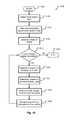
- FIG. 14is a flow diagram of a method for autonomously driving a vehicle in accordance with embodiments of the present disclosure
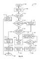
- FIG. 15is a flow diagram of a method for providing an escape route to an occupant within a vehicle in accordance with embodiments of the present disclosure
- FIG. 16illustrates an example of an escape route environment for an occupant of a vehicle in accordance with embodiments of the present disclosure
- FIG. 17Ashows a first state of a graphical user interface used in presenting an escape route to an occupant of a vehicle in accordance with embodiments of the present disclosure
- FIG. 17Bshows a second state of the graphical user interface of FIG. 17A ;
- FIG. 18is a flow diagram of a method for assisting limited capability individuals in a vehicle in accordance with embodiments of the present disclosure
- FIG. 19is a flow diagram of a first method for disconnecting a charging connector from a vehicle in accordance with embodiments of the present disclosure
- FIG. 20is a flow diagram of a second method for disconnecting a charging connector from a vehicle in accordance with embodiments of the present disclosure
- FIG. 21Ais a side view of an electric vehicle charging system in accordance with embodiments of the present disclosure.
- FIG. 21Bis an end view of a charging handle of the electric vehicle charging system of FIG. 21A ;
- FIG. 22is a section view of a charging receptacle in accordance with embodiments of the present disclosure.
- FIG. 23Ais a section view of a charging connector aligning with a charging receptacle for engagement in accordance with embodiments of the present disclosure
- FIG. 23Bis a section view of a charging connector in a first engagement state with a charging receptacle in accordance with embodiments of the present disclosure
- FIG. 23Cis a section view of a charging connector connected to a charging receptacle in accordance with embodiments of the present disclosure
- FIG. 24Ais a section view of a charging connector and charging receptacle in a first ejection state in accordance with embodiments of the present disclosure
- FIG. 24Bis a section view of a charging connector and charging receptacle in a second ejection state in accordance with embodiments of the present disclosure
- FIG. 25Ais a section view of a charging connector and charging receptacle in a first disconnection state in accordance with embodiments of the present disclosure.
- FIG. 25Bis a section view of a charging connector and charging receptacle in a second disconnection state in accordance with embodiments of the present disclosure.
- Embodiments of the present disclosurewill be described in connection with a vehicle, and in some embodiments, an electric vehicle, rechargeable electric vehicle, and/or hybrid-electric vehicle and associated systems.
- FIG. 1shows a perspective view of a vehicle 100 in accordance with embodiments of the present disclosure.
- the electric vehicle 100comprises a vehicle front 110 , vehicle aft or rear 120 , vehicle roof 130 , at least one vehicle side 160 , a vehicle undercarriage 140 , and a vehicle interior 150 .
- the vehicle 100may include a frame 104 and one or more body panels 108 mounted or affixed thereto.
- the vehicle 100may include one or more interior components (e.g., components inside an interior space 150 , or user space, of a vehicle 100 , etc.), exterior components (e.g., components outside of the interior space 150 , or user space, of a vehicle 100 , etc.), drive systems, controls systems, structural components, etc.
- the vehicle 100 described hereinmay include any conveyance or model of a conveyance, where the conveyance was designed for the purpose of moving one or more tangible objects, such as people, animals, cargo, and the like.
- vehicledoes not require that a conveyance moves or is capable of movement.
- Typical vehiclesmay include but are in no way limited to cars, trucks, motorcycles, busses, automobiles, trains, railed conveyances, boats, ships, marine conveyances, submarine conveyances, airplanes, space craft, flying machines, human-powered conveyances, and the like.
- the vehicle 100may include a number of sensors, devices, and/or systems that are capable of assisting in driving operations, e.g., autonomous or semi-autonomous control.
- the various sensors and systemsmay include, but are in no way limited to, one or more of cameras (e.g., independent, stereo, combined image, etc.), infrared (IR) sensors, radio frequency (RF) sensors, ultrasonic sensors (e.g., transducers, transceivers, etc.), RADAR sensors (e.g., object-detection sensors and/or systems), LIDAR (Light Imaging, Detection, And Ranging) systems, odometry sensors and/or devices (e.g., encoders, etc.), orientation sensors (e.g., accelerometers, gyroscopes, magnetometer, etc.), navigation sensors and systems (e.g., GPS, etc.), and other ranging, imaging, and/or object-detecting sensors.
- camerase.g., independent, stereo, combined image
- the sensorsmay be disposed in an interior space 150 of the vehicle 100 and/or on an outside of the vehicle 100 .
- the sensors and systemsmay be disposed in one or more portions of a vehicle 100 (e.g., the frame 104 , a body panel, a compartment, etc.).
- the vehicle sensors and systemsmay be selected and/or configured to suit a level of operation associated with the vehicle 100 .
- the number of sensors used in a systemmay be altered to increase or decrease information available to a vehicle control system (e.g., affecting control capabilities of the vehicle 100 ).
- the sensors and systemsmay be part of one or more advanced driver assistance systems (ADAS) associated with a vehicle 100 .
- ADASadvanced driver assistance systems
- the sensors and systemsmay be used to provide driving assistance at any level of operation (e.g., from fully-manual to fully-autonomous operations, etc.) as described herein.
- the various levels of vehicle control and/or operationcan be described as corresponding to a level of autonomy associated with a vehicle 100 for vehicle driving operations.
- a drivere.g., a human driver
- the vehiclemay be responsible for a limited number of the driving operations associated with the vehicle, while the driver is still responsible for most driving control operations.
- An example of a Level 1 vehiclemay include a vehicle in which the throttle control and/or braking operations may be controlled by the vehicle (e.g., cruise control operations, etc.).
- Level 1may be referred to as a “Driver Assistance” level.
- the vehiclemay collect information (e.g., via one or more driving assistance systems, sensors, etc.) about an environment of the vehicle (e.g., surrounding area, roadway, traffic, ambient conditions, etc.) and use the collected information to control driving operations (e.g., steering, accelerating, braking, etc.) associated with the vehicle.
- driving operationse.g., steering, accelerating, braking, etc.
- Level 2may be referred to as a “Partial Automation” level. It should be appreciated that Levels 0-2 all involve the driver monitoring the driving operations of the vehicle.
- the drivermay be separated from controlling all the driving operations of the vehicle except when the vehicle makes a request for the operator to act or intervene in controlling one or more driving operations. In other words, the driver may be separated from controlling the vehicle unless the driver is required to take over for the vehicle. Level 3 may be referred to as a “Conditional Automation” level.
- Level 4the driver may be separated from controlling all the driving operations of the vehicle and the vehicle may control driving operations even when a user fails to respond to a request to intervene. Level 4 may be referred to as a “High Automation” level.
- the vehiclecan control all the driving operations associated with the vehicle in all driving modes. The vehicle in Level 5 may continually monitor traffic, vehicular, roadway, and/or environmental conditions while driving the vehicle.
- Level 5there is no human driver interaction required in any driving mode. Accordingly, Level 5 may be referred to as a “Full Automation” level. It should be appreciated that in Levels 3-5 the vehicle, and/or one or more automated driving systems associated with the vehicle, monitors the driving operations of the vehicle and the driving environment.
- the vehicle 100may, for example, include at least one of a ranging and imaging system 112 (e.g., LIDAR, etc.), an imaging sensor 116 A, 116 F (e.g., camera, IR, etc.), a radio object-detection and ranging system sensors 116 B (e.g., RADAR, RF, etc.), ultrasonic sensors 116 C, and/or other object-detection sensors 116 D, 116 E.
- the LIDAR system 112 and/or sensorsmay be mounted on a roof 130 of the vehicle 100 .
- the RADAR sensors 116 Bmay be disposed at least at a front 110 , aft 120 , or side 160 of the vehicle 100 .
- the RADAR sensorsmay be used to monitor and/or detect a position of other vehicles, pedestrians, and/or other objects near, or proximal to, the vehicle 100 . While shown associated with one or more areas of a vehicle 100 , it should be appreciated that any of the sensors and systems 116 A-K, 112 illustrated in FIGS. 1 and 2 may be disposed in, on, and/or about the vehicle 100 in any position, area, and/or zone of the vehicle 100 .
- FIG. 2shows a vehicle sensing environment 200 at least partially defined by the sensors and systems 116 A-K, 112 disposed in, on, and/or about the vehicle 100 .
- Each sensor 116 A-Kmay include an operational detection range R and operational detection angle.
- the operational detection range Rmay define the effective detection limit, or distance, of the sensor 116 A-K. In some cases, this effective detection limit may be defined as a distance from a portion of the sensor 116 A-K (e.g., a lens, sensing surface, etc.) to a point in space offset from the sensor 116 A-K.
- the effective detection limitmay define a distance, beyond which, the sensing capabilities of the sensor 116 A-K deteriorate, fail to work, or are unreliable. In some embodiments, the effective detection limit may define a distance, within which, the sensing capabilities of the sensor 116 A-K are able to provide accurate and/or reliable detection information.
- the operational detection anglemay define at least one angle of a span, or between horizontal and/or vertical limits, of a sensor 116 A-K. As can be appreciated, the operational detection limit and the operational detection angle of a sensor 116 A-K together may define the effective detection zone 216 A-D (e.g., the effective detection area, and/or volume, etc.) of a sensor 116 A-K.
- the vehicle 100may include a ranging and imaging system 112 such as LIDAR, or the like.
- the ranging and imaging system 112may be configured to detect visual information in an environment surrounding the vehicle 100 .
- the visual information detected in the environment surrounding the ranging and imaging system 112may be processed (e.g., via one or more sensor and/or system processors, etc.) to generate a complete 360-degree view of an environment 200 around the vehicle.
- the ranging and imaging system 112may be configured to generate changing 360-degree views of the environment 200 in real-time, for instance, as the vehicle 100 drives.
- the ranging and imaging system 112may have an effective detection limit 204 that is some distance from the center of the vehicle 100 outward over 360 degrees.
- the effective detection limit 204 of the ranging and imaging system 112defines a view zone 208 (e.g., an area and/or volume, etc.) surrounding the vehicle 100 . Any object falling outside of the view zone 208 is in the undetected zone 212 and would not be detected by the ranging and imaging system 112 of the vehicle 100 .
- a view zone 208e.g., an area and/or volume, etc.
- Sensor data and informationmay be collected by one or more sensors or systems 116 A-K, 112 of the vehicle 100 monitoring the vehicle sensing environment 200 .
- This informationmay be processed (e.g., via a processor, computer-vision system, etc.) to determine targets (e.g., objects, signs, people, markings, roadways, conditions, etc.) inside one or more detection zones 208 , 216 A-D associated with the vehicle sensing environment 200 .
- targetse.g., objects, signs, people, markings, roadways, conditions, etc.
- information from multiple sensors 116 A-Kmay be processed to form composite sensor detection information.
- a first sensor 116 A and a second sensor 116 Fmay correspond to a first camera 116 A and a second camera 116 F aimed in a forward traveling direction of the vehicle 100 .
- images collected by the cameras 116 A, 116 Fmay be combined to form stereo image information.
- This composite informationmay increase the capabilities of a single sensor in the one or more sensors 116 A-K by, for example, adding the ability to determine depth associated with targets in the one or more detection zones 208 , 216 A-D.
- Similar image datamay be collected by rear view cameras (e.g., sensors 116 G, 116 H) aimed in a rearward traveling direction vehicle 100 .
- multiple sensors 116 A-Kmay be effectively joined to increase a sensing zone and provide increased sensing coverage.
- multiple RADAR sensors 116 B disposed on the front 110 of the vehiclemay be joined to provide a zone 216 B of coverage that spans across an entirety of the front 110 of the vehicle.
- the multiple RADAR sensors 116 Bmay cover a detection zone 216 B that includes one or more other sensor detection zones 216 A. These overlapping detection zones may provide redundant sensing, enhanced sensing, and/or provide greater detail in sensing within a particular portion (e.g., zone 216 A) of a larger zone (e.g., zone 216 B).
- the sensors 116 A-K of the vehicle 100may be arranged to create a complete coverage, via one or more sensing zones 208 , 216 A-D around the vehicle 100 .
- the sensing zones 216 C of two or more sensors 116 D, 116 Emay intersect at an overlap zone 220 .
- the angle and/or detection limit of two or more sensing zones 216 C, 216 D(e.g., of two or more sensors 116 E, 116 J, 116 K) may meet at a virtual intersection point 224 .
- the vehicle 100may include a number of sensors 116 E, 116 G, 116 H, 116 J, 116 K disposed proximal to the rear 120 of the vehicle 100 .
- These sensorscan include, but are in no way limited to, an imaging sensor, camera, IR, a radio object-detection and ranging sensors, RADAR, RF, ultrasonic sensors, and/or other object-detection sensors.
- these sensors 116 E, 116 G, 116 H, 116 J, 116 Kmay detect targets near or approaching the rear of the vehicle 100 .
- another vehicle approaching the rear 120 of the vehicle 100may be detected by one or more of the ranging and imaging system (e.g., LIDAR) 112 , rear-view cameras 116 G, 116 H, and/or rear facing RADAR sensors 116 J, 116 K.
- the images from the rear-view cameras 116 G, 116 Hmay be processed to generate a stereo view (e.g., providing depth associated with an object or environment, etc.) for targets visible to both cameras 116 G, 116 H.
- the vehicle 100may be driving and one or more of the ranging and imaging system 112 , front-facing cameras 116 A, 116 F, front-facing RADAR sensors 116 B, and/or ultrasonic sensors 116 C may detect targets in front of the vehicle 100 .
- This approachmay provide critical sensor information to a vehicle control system in at least one of the autonomous driving levels described above.
- the sensor detection informationmay be sent to the vehicle control system of the vehicle 100 to control a driving operation (e.g., braking, decelerating, etc.) associated with the vehicle 100 (in this example, slowing the vehicle 100 as to avoid colliding with the stopped other vehicles).
- a driving operatione.g., braking, decelerating, etc.
- the vehicle 100may be operating and one or more of the ranging and imaging system 112 , and/or the side-facing sensors 116 D, 116 E (e.g., RADAR, ultrasonic, camera, combinations thereof, and/or other type of sensor), may detect targets at a side of the vehicle 100 .
- the sensors 116 A-Kmay detect a target that is both at a side 160 and a front 110 of the vehicle 100 (e.g., disposed at a diagonal angle to a centerline of the vehicle 100 running from the front 110 of the vehicle 100 to the rear 120 of the vehicle). Additionally or alternatively, the sensors 116 A-K may detect a target that is both, or simultaneously, at a side 160 and a rear 120 of the vehicle 100 (e.g., disposed at a diagonal angle to the centerline of the vehicle 100 ).
- FIGS. 3A-3Care block diagrams of an embodiment of a communication environment 300 of the vehicle 100 in accordance with embodiments of the present disclosure.
- the communication system 300may include one or more vehicle driving vehicle sensors and systems 304 , sensor processors 340 , sensor data memory 344 , vehicle control system 348 , communications subsystem 350 , control data 364 , computing devices 368 , display devices 372 , and other components 374 that may be associated with a vehicle 100 .
- These associated componentsmay be electrically and/or communicatively coupled to one another via at least one bus 360 .
- the one or more associated componentsmay send and/or receive signals across a communication network 352 to at least one of a navigation source 356 A, a control source 356 B, or some other entity 356 N.
- the communication network 352may comprise any type of known communication medium or collection of communication media and may use any type of protocols, such as SIP, TCP/IP, SNA, IPX, AppleTalk, and the like, to transport messages between endpoints.
- the communication network 352may include wired and/or wireless communication technologies.
- the Internetis an example of the communication network 352 that constitutes an Internet Protocol (IP) network consisting of many computers, computing networks, and other communication devices located all over the world, which are connected through many telephone systems and other means.
- IPInternet Protocol
- the communication network 104include, without limitation, a standard Plain Old Telephone System (POTS), an Integrated Services Digital Network (ISDN), the Public Switched Telephone Network (PSTN), a Local Area Network (LAN), such as an Ethernet network, a Token-Ring network and/or the like, a Wide Area Network (WAN), a virtual network, including without limitation a virtual private network (“VPN”); the Internet, an intranet, an extranet, a cellular network, an infra-red network; a wireless network (e.g., a network operating under any of the IEEE 802.9 suite of protocols, the Bluetooth® protocol known in the art, and/or any other wireless protocol), and any other type of packet-switched or circuit-switched network known in the art and/or any combination of these and/or other networks.
- POTSPlain Old Telephone System
- ISDNIntegrated Services Digital Network
- PSTNPublic Switched Telephone Network
- LANLocal Area Network
- VPNvirtual private network
- the Internetan intranet, an extranet, a cellular
- the communication network 352need not be limited to any one network type, and instead may be comprised of a number of different networks and/or network types.
- the communication network 352may comprise a number of different communication media such as coaxial cable, copper cable/wire, fiber-optic cable, antennas for transmitting/receiving wireless messages, and combinations thereof.
- the driving vehicle sensors and systems 304may include at least one navigation 308 (e.g., global positioning system (GPS), etc.), orientation 312 , odometry 316 , LIDAR 320 , RADAR 324 , ultrasonic 328 , camera 332 , infrared (IR) 336 , and/or other sensor or system 338 .
- GPSglobal positioning system
- IRinfrared
- These driving vehicle sensors and systems 304may be similar, if not identical, to the sensors and systems 116 A-K, 112 described in conjunction with FIGS. 1 and 2 .
- the navigation sensor 308may include one or more sensors having receivers and antennas that are configured to utilize a satellite-based navigation system including a network of navigation satellites capable of providing geolocation and time information to at least one component of the vehicle 100 .
- Examples of the navigation sensor 308 as described hereinmay include, but are not limited to, at least one of Garmin® GLOTM family of GPS and GLONASS combination sensors, Garmin® GPS 15xTM family of sensors, Garmin® GPS 16xTM family of sensors with high-sensitivity receiver and antenna, Garmin® GPS 18x OEM family of high-sensitivity GPS sensors, Dewetron DEWE-VGPS series of GPS sensors, GlobalSat 1-Hz series of GPS sensors, other industry-equivalent navigation sensors and/or systems, and may perform navigational and/or geolocation functions using any known or future-developed standard and/or architecture.
- the orientation sensor 312may include one or more sensors configured to determine an orientation of the vehicle 100 relative to at least one reference point.
- the orientation sensor 312may include at least one pressure transducer, stress/strain gauge, accelerometer, gyroscope, and/or geomagnetic sensor.
- Examples of the navigation sensor 308 as described hereinmay include, but are not limited to, at least one of Bosch Sensortec BMX 160 series low-power absolute orientation sensors, Bosch Sensortec BMX055 9-axis sensors, Bosch Sensortec BMI055 6-axis inertial sensors, Bosch Sensortec BMI160 6-axis inertial sensors, Bosch Sensortec BMF055 9-axis inertial sensors (accelerometer, gyroscope, and magnetometer) with integrated Cortex M0+ microcontroller, Bosch Sensortec BMP280 absolute barometric pressure sensors, Infineon TLV493D-A1B6 3D magnetic sensors, Infineon TLI493D-W1B6 3D magnetic sensors, Infineon TL family of 3D magnetic sensors, Murata Electronics SCC2000 series combined gyro sensor and accelerometer, Murata Electronics SCC1300 series combined gyro sensor and accelerometer, other industry-equivalent orientation sensors and/or systems, which may perform orientation detection and/or determination functions using any known or future-
- the odometry sensor and/or system 316may include one or more components that is configured to determine a change in position of the vehicle 100 over time.
- the odometry system 316may utilize data from one or more other sensors and/or systems 304 in determining a position (e.g., distance, location, etc.) of the vehicle 100 relative to a previously measured position for the vehicle 100 .
- the odometry sensors 316may include one or more encoders, Hall speed sensors, and/or other measurement sensors/devices configured to measure a wheel speed, rotation, and/or number of revolutions made over time.
- Examples of the odometry sensor/system 316 as described hereinmay include, but are not limited to, at least one of Infineon TLE4924/26/27/28C high-performance speed sensors, Infineon TL4941plusC(B) single chip differential Hall wheel-speed sensors, Infineon TL5041plusC Giant Mangnetoresistance (GMR) effect sensors, Infineon TL family of magnetic sensors, EPC Model 25SP Accu-CoderProTM incremental shaft encoders, EPC Model 30M compact incremental encoders with advanced magnetic sensing and signal processing technology, EPC Model 925 absolute shaft encoders, EPC Model 958 absolute shaft encoders, EPC Model MA36S/MA63S/SA36S absolute shaft encoders, DynaparTM F18 commutating optical encoder, DynaparTM HS35R family of phased array encoder sensors, other industry-equivalent odometry sensors and/or systems, and may perform change in position detection and/or determination functions using any known or future-developed standard and/or
- the LIDAR sensor/system 320may include one or more components configured to measure distances to targets using laser illumination.
- the LIDAR sensor/system 320may provide 3D imaging data of an environment around the vehicle 100 .
- the imaging datamay be processed to generate a full 360-degree view of the environment around the vehicle 100 .
- the LIDAR sensor/system 320may include a laser light generator configured to generate a plurality of target illumination laser beams (e.g., laser light channels). In some embodiments, this plurality of laser beams may be aimed at, or directed to, a rotating reflective surface (e.g., a mirror) and guided outwardly from the LIDAR sensor/system 320 into a measurement environment.
- a rotating reflective surfacee.g., a mirror
- the rotating reflective surfacemay be configured to continually rotate 360 degrees about an axis, such that the plurality of laser beams is directed in a full 360-degree range around the vehicle 100 .
- a photodiode receiver of the LIDAR sensor/system 320may detect when light from the plurality of laser beams emitted into the measurement environment returns (e.g., reflected echo) to the LIDAR sensor/system 320 .
- the LIDAR sensor/system 320may calculate, based on a time associated with the emission of light to the detected return of light, a distance from the vehicle 100 to the illuminated target.
- the LIDAR sensor/system 320may generate over 2.0 million points per second and have an effective operational range of at least 100 meters.
- Examples of the LIDAR sensor/system 320 as described hereinmay include, but are not limited to, at least one of Velodyne® LiDARTM HDL-64E 64-channel LIDAR sensors, Velodyne® LiDARTM HDL-32E 32-channel LIDAR sensors, Velodyne® LiDARTM PUCKTM VLP-16 16-channel LIDAR sensors, Leica Geosystems Pegasus: Two mobile sensor platform, Garmin® LIDAR-Lite v3 measurement sensor, Quanergy M8 LiDAR sensors, Quanergy S3 solid state LiDAR sensor, LeddarTech® LeddarVU compact solid state fixed-beam LIDAR sensors, other industry-equivalent LIDAR sensors and/or systems, and may perform illuminated target and/or obstacle detection in an environment around the vehicle 100 using any known or future-developed standard and/or architecture.
- the RADAR sensors 324may include one or more radio components that are configured to detect objects/targets in an environment of the vehicle 100 .
- the RADAR sensors 324may determine a distance, position, and/or movement vector (e.g., angle, speed, etc.) associated with a target over time.
- the RADAR sensors 324may include a transmitter configured to generate and emit electromagnetic waves (e.g., radio, microwaves, etc.) and a receiver configured to detect returned electromagnetic waves.
- the RADAR sensors 324may include at least one processor configured to interpret the returned electromagnetic waves and determine locational properties of targets.
- Examples of the RADAR sensors 324 as described hereinmay include, but are not limited to, at least one of Infineon RASICTM RTN7735PL transmitter and RRN7745PL/46PL receiver sensors, Autoliv ASP Vehicle RADAR sensors, Delphi L2C0051TR 77 GHz ESR Electronically Scanning Radar sensors, Fujitsu Ten Ltd. Automotive Compact 77 GHz 3D Electronic Scan Millimeter Wave Radar sensors, other industry-equivalent RADAR sensors and/or systems, and may perform radio target and/or obstacle detection in an environment around the vehicle 100 using any known or future-developed standard and/or architecture.
- the ultrasonic sensors 328may include one or more components that are configured to detect objects/targets in an environment of the vehicle 100 .
- the ultrasonic sensors 328may determine a distance, position, and/or movement vector (e.g., angle, speed, etc.) associated with a target over time.
- the ultrasonic sensors 328may include an ultrasonic transmitter and receiver, or transceiver, configured to generate and emit ultrasound waves and interpret returned echoes of those waves.
- the ultrasonic sensors 328may include at least one processor configured to interpret the returned ultrasonic waves and determine locational properties of targets.
- Examples of the ultrasonic sensors 328 as described hereinmay include, but are not limited to, at least one of Texas Instruments TIDA-00151 automotive ultrasonic sensor interface IC sensors, MaxBotix® MB8450 ultrasonic proximity sensor, MaxBotix® ParkSonarTM-EZ ultrasonic proximity sensors, Murata Electronics MA40H1S-R open-structure ultrasonic sensors, Murata Electronics MA40S4R/S open-structure ultrasonic sensors, Murata Electronics MA58MF14-7N waterproof ultrasonic sensors, other industry-equivalent ultrasonic sensors and/or systems, and may perform ultrasonic target and/or obstacle detection in an environment around the vehicle 100 using any known or future-developed standard and/or architecture.
- the camera sensors 332may include one or more components configured to detect image information associated with an environment of the vehicle 100 .
- the camera sensors 332may include a lens, filter, image sensor, and/or a digital image processor. It is an aspect of the present disclosure that multiple camera sensors 332 may be used together to generate stereo images providing depth measurements.
- Examples of the camera sensors 332 as described hereinmay include, but are not limited to, at least one of ON Semiconductor® MT9V024 Global Shutter VGA GS CMOS image sensors, Teledyne DALSA Falcon2 camera sensors, CMOSIS CMV50000 high-speed CMOS image sensors, other industry-equivalent camera sensors and/or systems, and may perform visual target and/or obstacle detection in an environment around the vehicle 100 using any known or future-developed standard and/or architecture.
- the infrared (IR) sensors 336may include one or more components configured to detect image information associated with an environment of the vehicle 100 .
- the IR sensors 336may be configured to detect targets in low-light, dark, or poorly-lit environments.
- the IR sensors 336may include an IR light emitting element (e.g., IR light emitting diode (LED), etc.) and an IR photodiode.
- the IR photodiodemay be configured to detect returned IR light at or about the same wavelength to that emitted by the IR light emitting element.
- the IR sensors 336may include at least one processor configured to interpret the returned IR light and determine locational properties of targets.
- the IR sensors 336may be configured to detect and/or measure a temperature associated with a target (e.g., an object, pedestrian, other vehicle, etc.).
- a targete.g., an object, pedestrian, other vehicle, etc.
- Examples of IR sensors 336 as described hereinmay include, but are not limited to, at least one of Opto Diode lead-salt IR array sensors, Opto Diode OD-850 Near-IR LED sensors, Opto Diode SA/SHA727 steady state IR emitters and IR detectors, FLIR® LS microbolometer sensors, FLIR® TacFLIR 380-HD InSb MWIR FPA and HD MWIR thermal sensors, FLIR® VOx 640 ⁇ 480 pixel detector sensors, Delphi IR sensors, other industry-equivalent IR sensors and/or systems, and may perform IR visual target and/or obstacle detection in an environment around the vehicle 100 using any known or future-developed standard and/or architecture.
- the vehicle 100can also include one or more interior sensors 337 .
- Interior sensors 337can measure characteristics of the inside environment of the vehicle 100 .
- the interior sensors 337may be as described in conjunction with FIG. 3B .
- a navigation system 302can include any hardware and/or software used to navigate the vehicle either manually or autonomously.
- the navigation system 302may be as described in conjunction with FIG. 3C .
- the driving vehicle sensors and systems 304may include other sensors 338 and/or combinations of the sensors 306 - 337 described above. Additionally or alternatively, one or more of the sensors 306 - 337 described above may include one or more processors configured to process and/or interpret signals detected by the one or more sensors 306 - 337 . In some embodiments, the processing of at least some sensor information provided by the vehicle sensors and systems 304 may be processed by at least one sensor processor 340 . Raw and/or processed sensor data may be stored in a sensor data memory 344 storage medium. In some embodiments, the sensor data memory 344 may store instructions used by the sensor processor 340 for processing sensor information provided by the sensors and systems 304 .
- the sensor data memory 344may be a disk drive, optical storage device, solid-state storage device such as a random access memory (“RAM”) and/or a read-only memory (“ROM”), which can be programmable, flash-updateable, and/or the like.
- RAMrandom access memory
- ROMread-only memory
- the vehicle control system 348may receive processed sensor information from the sensor processor 340 and determine to control an aspect of the vehicle 100 . Controlling an aspect of the vehicle 100 may include presenting information via one or more display devices 372 associated with the vehicle, sending commands to one or more computing devices 368 associated with the vehicle, and/or controlling a driving operation of the vehicle. In some embodiments, the vehicle control system 348 may correspond to one or more computing systems that control driving operations of the vehicle 100 in accordance with the Levels of driving autonomy described above. In one embodiment, the vehicle control system 348 may operate a speed of the vehicle 100 by controlling an output signal to the accelerator and/or braking system of the vehicle.
- the vehicle control system 348may receive sensor data describing an environment surrounding the vehicle 100 and, based on the sensor data received, determine to adjust the acceleration, power output, and/or braking of the vehicle 100 .
- the vehicle control system 348may additionally control steering and/or other driving functions of the vehicle 100 .
- the vehicle control system 348may communicate, in real-time, with the driving sensors and systems 304 forming a feedback loop.
- the vehicle control system 348may autonomously make changes to a driving operation of the vehicle 100 .
- the vehicle control system 348may then receive subsequent sensor information describing any change to the condition of the targets detected in the environment as a result of the changes made to the driving operation.
- This continual cycle of observatione.g., via the sensors, etc.
- actione.g., selected control or non-control of vehicle operations, etc.
- the one or more components of the vehicle 100may communicate across the communication network 352 to one or more entities 356 A-N via a communications subsystem 350 of the vehicle 100 .
- a communications subsystem 350Embodiments of the communications subsystem 350 are described in greater detail in conjunction with FIG. 5 .
- the navigation sensors 308may receive global positioning, location, and/or navigational information from a navigation source 356 A.
- the navigation source 356 Amay be a global navigation satellite system (GNSS) similar, if not identical, to NAVSTAR GPS, GLONASS, EU Galileo, and/or the BeiDou Navigation Satellite System (BDS) to name a few.
- GNSSglobal navigation satellite system
- the vehicle control system 348may receive control information from one or more control sources 356 B.
- the control source 356may provide vehicle control information including autonomous driving control commands, vehicle operation override control commands, and the like.
- the control source 356may correspond to an autonomous vehicle control system, a traffic control system, an administrative control entity, and/or some other controlling server. It is an aspect of the present disclosure that the vehicle control system 348 and/or other components of the vehicle 100 may exchange communications with the control source 356 across the communication network 352 and via the communications subsystem 350 .
- control data memory 364may store instructions used by the vehicle control system 348 for controlling driving operations of the vehicle 100 , historical control information, autonomous driving control rules, and the like.
- the control data memory 364may be a disk drive, optical storage device, solid-state storage device such as a random access memory (“RAM”) and/or a read-only memory (“ROM”), which can be programmable, flash-updateable, and/or the like.
- the vehicle 100may include a number of user interface devices.
- the user interface devicesreceive and translate human input into a mechanical movement or electrical signal or stimulus.
- the human inputmay be one or more of motion (e.g., body movement, body part movement, in two-dimensional or three-dimensional space, etc.), voice, touch, and/or physical interaction with the components of the vehicle 100 .
- the human inputmay be configured to control one or more functions of the vehicle 100 and/or systems of the vehicle 100 described herein.
- User interfacesmay include, but are in no way limited to, at least one graphical user interface of a display device, steering wheel or mechanism, transmission lever or button (e.g., including park, neutral, reverse, and/or drive positions, etc.), throttle control pedal or mechanism, brake control pedal or mechanism, power control switch, communications equipment, etc.
- transmission lever or buttone.g., including park, neutral, reverse, and/or drive positions, etc.
- FIG. 3Bshows a block diagram of an embodiment of interior sensors 337 for a vehicle 100 .
- the interior sensors 337may be arranged into one or more groups, based at least partially on the function of the interior sensors 337 .
- the interior space of a vehicle 100may include environmental sensors, user interface sensor(s), and/or safety sensors. Additionally or alternatively, there may be sensors associated with various devices inside the vehicle (e.g., smart phones, tablets, mobile computers, wearables, etc.)
- Environmental sensorsmay comprise sensors configured to collect data relating to the internal environment of a vehicle 100 .
- Examples of environmental sensorsmay include one or more of, but are not limited to: oxygen/air sensors 301 , temperature sensors 303 , humidity sensors 305 , light/photo sensors 307 , and more.
- the oxygen/air sensors 301may be configured to detect a quality or characteristic of the air in the interior space 108 of the vehicle 100 (e.g., ratios and/or types of gasses comprising the air inside the vehicle 100 , dangerous gas levels, safe gas levels, etc.).
- Temperature sensors 303may be configured to detect temperature readings of one or more objects, users 216 , and/or areas of a vehicle 100 .
- Humidity sensors 305may detect an amount of water vapor present in the air inside the vehicle 100 .
- the light/photo sensors 307can detect an amount of light present in the vehicle 100 . Further, the light/photo sensors 307 may be configured to detect various levels of light intensity associated with light in the vehicle 100 .
- User interface sensorsmay comprise sensors configured to collect data relating to one or more users (e.g., a driver and/or passenger(s)) in a vehicle 100 .
- the user interface sensorsmay include sensors that are configured to collect data from users 216 in one or more areas of the vehicle 100 .
- Examples of user interface sensorsmay include one or more of, but are not limited to: infrared sensors 309 , motion sensors 311 , weight sensors 313 , wireless network sensors 315 , biometric sensors 317 , camera (or image) sensors 319 , audio sensors 321 , and more.
- Infrared sensors 309may be used to measure IR light irradiating from at least one surface, user, or other object in the vehicle 100 .
- the Infrared sensors 309may be used to measure temperatures, form images (especially in low light conditions), identify users 216 , and even detect motion in the vehicle 100 .
- the motion sensors 311may detect motion and/or movement of objects inside the vehicle 104 .
- the motion sensors 311may be used alone or in combination to detect movement.
- a usermay be operating a vehicle 100 (e.g., while driving, etc.) when a passenger in the rear of the vehicle 100 unbuckles a safety belt and proceeds to move about the vehicle 10 .
- the movement of the passengercould be detected by the motion sensors 311 .
- the passengermay be prevented from interfacing with and/or accessing at least some of the vehicle control features.
- the usermay be alerted of the movement/motion such that the user can act to prevent the passenger from interfering with the vehicle controls.
- the number of motion sensors in a vehiclemay be increased to increase an accuracy associated with motion detected in the vehicle 100 .
- Weight sensors 313may be employed to collect data relating to objects and/or users in various areas of the vehicle 100 .
- the weight sensors 313may be included in the seats and/or floor of a vehicle 100 .
- the vehicle 100may include a wireless network sensor 315 .
- This sensor 315may be configured to detect one or more wireless network(s) inside the vehicle 100 .
- wireless networksmay include, but are not limited to, wireless communications utilizing Bluetooth®, Wi-FiTM, ZigBee, IEEE 802.11, and other wireless technology standards.
- a mobile hotspotmay be detected inside the vehicle 100 via the wireless network sensor 315 .
- the vehicle 100may determine to utilize and/or share the mobile hotspot detected via/with one or more other devices associated with the vehicle 100 .
- Biometric sensors 317may be employed to identify and/or record characteristics associated with a user. It is anticipated that biometric sensors 317 can include at least one of image sensors, IR sensors, fingerprint readers, weight sensors, load cells, force transducers, heart rate monitors, blood pressure monitors, and the like as provided herein.
- the camera sensors 319may record still images, video, and/or combinations thereof. Camera sensors 319 may be used alone or in combination to identify objects, users, and/or other features, inside the vehicle 100 . Two or more camera sensors 319 may be used in combination to form, among other things, stereo and/or three-dimensional (3D) images. The stereo images can be recorded and/or used to determine depth associated with objects and/or users in a vehicle 100 . Further, the camera sensors 319 used in combination may determine the complex geometry associated with identifying characteristics of a user.
- the camera sensors 319may be used to determine dimensions between various features of a user's face (e.g., the depth/distance from a user's nose to a user's cheeks, a linear distance between the center of a user's eyes, and more). These dimensions may be used to verify, record, and even modify characteristics that serve to identify a user.
- the camera sensors 319may also be used to determine movement associated with objects and/or users within the vehicle 100 . It should be appreciated that the number of image sensors used in a vehicle 100 may be increased to provide greater dimensional accuracy and/or views of a detected image in the vehicle 100 .
- the audio sensors 321may be configured to receive audio input from a user of the vehicle 100 .
- the audio input from a usermay correspond to voice commands, conversations detected in the vehicle 100 , phone calls made in the vehicle 100 , and/or other audible expressions made in the vehicle 100 .
- Audio sensors 321may include, but are not limited to, microphones and other types of acoustic-to-electric transducers or sensors.
- the interior audio sensors 321may be configured to receive and convert sound waves into an equivalent analog or digital signal.
- the interior audio sensors 321may serve to determine one or more locations associated with various sounds in the vehicle 100 . The location of the sounds may be determined based on a comparison of volume levels, intensity, and the like, between sounds detected by two or more interior audio sensors 321 .
- a first audio sensors 321may be located in a first area of the vehicle 100 and a second audio sensors 321 may be located in a second area of the vehicle 100 . If a sound is detected at a first volume level by the first audio sensors 321 A and a second, higher, volume level by the second audio sensors 321 in the second area of the vehicle 100 , the sound may be determined to be closer to the second area of the vehicle 100 .
- the number of sound receivers used in a vehicle 100may be increased (e.g., more than two, etc.) to increase measurement accuracy surrounding sound detection and location, or source, of the sound (e.g., via triangulation, etc.).
- the safety sensorsmay comprise sensors configured to collect data relating to the safety of a user and/or one or more components of a vehicle 100 .
- Examples of safety sensorsmay include one or more of, but are not limited to: force sensors 325 , mechanical motion sensors 327 , orientation sensors 329 , restraint sensors 331 , and more.
- the force sensors 325may include one or more sensors inside the vehicle 100 configured to detect a force observed in the vehicle 100 .
- a force sensor 325may include a force transducer that converts measured forces (e.g., force, weight, pressure, etc.) into output signals.
- Mechanical motion sensors 327may correspond to encoders, accelerometers, damped masses, and the like.
- the mechanical motion sensors 327may be adapted to measure the force of gravity (i.e., G-force) as observed inside the vehicle 100 . Measuring the G-force observed inside a vehicle 100 can provide valuable information related to a vehicle's acceleration, deceleration, collisions, and/or forces that may have been suffered by one or more users in the vehicle 100 .
- Orientation sensors 329can include accelerometers, gyroscopes, magnetic sensors, and the like that are configured to detect an orientation associated with the vehicle 100 .
- the restraint sensors 331may correspond to sensors associated with one or more restraint devices and/or systems in a vehicle 100 .
- Seatbelts and airbagsare examples of restraint devices and/or systems.
- the restraint devices and/or systemsmay be associated with one or more sensors that are configured to detect a state of the device/system.
- the statemay include extension, engagement, retraction, disengagement, deployment, and/or other electrical or mechanical conditions associated with the device/system.
- the associated device sensors 323can include any sensors that are associated with a device in the vehicle 100 .
- typical devicesmay include smart phones, tablets, laptops, mobile computers, and the like. It is anticipated that the various sensors associated with these devices can be employed by the vehicle control system 348 .
- a typical smart phonecan include, an image sensor, an IR sensor, audio sensor, gyroscope, accelerometer, wireless network sensor, fingerprint reader, and more. It is an aspect of the present disclosure that one or more of these associated device sensors 323 may be used by one or more subsystems of the vehicle 100 .
- FIG. 3Cillustrates a GPS/Navigation subsystem(s) 302 .
- the navigation subsystem(s) 302can be any present or future-built navigation system that may use location data, for example, from the Global Positioning System (GPS), to provide navigation information or control the vehicle 100 .
- the navigation subsystem(s) 302can include several components, such as, one or more of, but not limited to: a GPS Antenna/receiver 331 , a location module 333 , a maps database 335 , etc.
- the several components or modules 331 - 335may be hardware, software, firmware, computer readable media, or combinations thereof.
- a GPS Antenna/receiver 331can be any antenna, GPS puck, and/or receiver capable of receiving signals from a GPS satellite or other navigation system.
- the signalsmay be demodulated, converted, interpreted, etc. by the GPS Antenna/receiver 331 and provided to the location module 333 .
- the GPS Antenna/receiver 331may convert the time signals from the GPS system and provide a location (e.g., coordinates on a map) to the location module 333 .
- the location module 333can interpret the time signals into coordinates or other location information.
- the location module 333can be the controller of the satellite navigation system designed for use in the vehicle 100 .
- the location module 333can acquire position data, as from the GPS Antenna/receiver 331 , to locate the user or vehicle 100 on a road in the unit's map database 335 .
- the location module 333can give directions to other locations along roads also in the database 335 .
- the location module 333may apply dead reckoning to estimate distance data from sensors 304 including one or more of, but not limited to, a speed sensor attached to the drive train of the vehicle 100 , a gyroscope, an accelerometer, etc.
- the location module 333may use known locations of Wi-Fi hotspots, cell tower data, etc. to determine the position of the vehicle 100 , such as by using time difference of arrival (TDOA) and/or frequency difference of arrival (FDOA) techniques.
- TDOAtime difference of arrival
- FDOAfrequency difference of arrival
- the maps database 335can include any hardware and/or software to store information about maps, geographical information system (GIS) information, location information, etc.
- the maps database 335can include any data definition or other structure to store the information.
- the maps database 335can include a road database that may include one or more vector maps of areas of interest. Street names, street numbers, house numbers, and other information can be encoded as geographic coordinates so that the user can find some desired destination by street address. Points of interest (waypoints) can also be stored with their geographic coordinates. For example, a point of interest may include speed cameras, fuel stations, public parking, and “parked here” (or “you parked here”) information.
- the maps database 335may also include road or street characteristics, for example, speed limits, location of stop lights/stop signs, lane divisions, school locations, etc.
- the map database contentscan be produced or updated by a server connected through a wireless system in communication with the Internet, even as the vehicle 100 is driven along existing streets, yielding an up-to-date map.
- FIG. 4shows one embodiment of the instrument panel 400 of the vehicle 100 .
- the instrument panel 400 of vehicle 100comprises a steering wheel 410 , a vehicle operational display 420 (e.g., configured to present and/or display driving data such as speed, measured air resistance, vehicle information, entertainment information, etc.), one or more auxiliary displays 424 (e.g., configured to present and/or display information segregated from the operational display 420 , entertainment applications, movies, music, etc.), a heads-up display 434 (e.g., configured to display any information previously described including, but in no way limited to, guidance information such as route to destination, or obstacle warning information to warn of a potential collision, or some or all primary vehicle operational data such as speed, resistance, etc.), a power management display 428 (e.g., configured to display data corresponding to electric power levels of vehicle 100 , reserve power, charging status, etc.), and an input device 432 (e.g., a controller, touchscreen, or other interface device configured to interface with one or more displays in the instrument
- the input device 432may be configured as a joystick, mouse, touchpad, tablet, 3D gesture capture device, etc.). In some embodiments, the input device 432 may be used to manually maneuver a portion of the vehicle 100 into a charging position (e.g., moving a charging plate to a desired separation distance, etc.).
- the vehicle operational displaymay be a display incapable of receiving touch input.
- the operational display 420 that spans across an interior space centerline 404 and across both a first zone 408 A and a second zone 408 Bmay be isolated from receiving input from touch, especially from a passenger.
- a display that provides vehicle operation or critical systems information and interfacemay be restricted from receiving touch input and/or be configured as a non-touch display. This type of configuration can prevent dangerous mistakes in providing touch input where such input may cause an accident or unwanted control.
- one or more displays of the instrument panel 400may be mobile devices and/or applications residing on a mobile device such as a smart phone. Additionally or alternatively, any of the information described herein may be presented to one or more portions 420 A-N of the operational display 420 or other display 424 , 428 , 434 . In one embodiment, one or more displays of the instrument panel 400 may be physically separated or detached from the instrument panel 400 . In some cases, a detachable display may remain tethered to the instrument panel.
- the portions 420 A-N of the operational display 420may be dynamically reconfigured and/or resized to suit any display of information as described. Additionally or alternatively, the number of portions 420 A-N used to visually present information via the operational display 420 may be dynamically increased or decreased as required, and are not limited to the configurations shown.
- FIG. 5illustrates a hardware diagram of communications componentry that can be optionally associated with the vehicle 100 in accordance with embodiments of the present disclosure.
- the communications componentrycan include one or more wired or wireless devices such as a transceiver(s) and/or modem that allows communications not only between the various systems disclosed herein but also with other devices, such as devices on a network, and/or on a distributed network such as the Internet and/or in the cloud and/or with other vehicle(s).
- a transceiver(s) and/or modemthat allows communications not only between the various systems disclosed herein but also with other devices, such as devices on a network, and/or on a distributed network such as the Internet and/or in the cloud and/or with other vehicle(s).
- the communications subsystem 350can also include inter- and intra-vehicle communications capabilities such as hotspot and/or access point connectivity for any one or more of the vehicle occupants and/or vehicle-to-vehicle communications.
- inter- and intra-vehicle communications capabilitiessuch as hotspot and/or access point connectivity for any one or more of the vehicle occupants and/or vehicle-to-vehicle communications.
- the communications subsystem 350can include one or more communications links (that can be wired or wireless) and/or communications busses (managed by the bus manager 574 ), including one or more of CAN FD, OBD-II, ARCINC 429, Byteflight, CAN (Controller Area Network), D2B (Domestic Digital Bus), FlexRay, DC-BUS, IDB-1394, IEBus, I2C, ISO 9141-1/-2, J1708, J1587, J1850, J1939, ISO 11783, Keyword Protocol 2000, LIN (Local Interconnect Network), MOST (Media Oriented Systems Transport), Multifunction Vehicle Bus, SMARTwireX, SPI, VAN (Vehicle Area Network), Ethernet bus, and the like or in general any communications protocol and/or standard(s).
- CAN FDController Area Network
- OBD-IIOBD-II
- ARCINC 429Byteflight
- CANController Area Network
- D2BDomestic Digital Bus
- the various protocols and communicationscan be communicated one or more of wirelessly and/or over transmission media such as single wire, twisted pair, fiber optic, IEEE 1394, MIL-STD-1553, MIL-STD-1773, power-line communication, or the like. (All of the above standards and protocols are incorporated herein by reference in their entirety).
- the communications subsystem 350enables communications between any of the inter-vehicle systems and subsystems as well as communications with non-collocated resources, such as those reachable over a network such as the Internet.
- the communications subsystem 350in addition to well-known componentry (which has been omitted for clarity), includes interconnected elements including one or more of: one or more antennas 504 , an interleaver/deinterleaver 508 , an analog front end (AFE) 512 , memory/storage/cache 516 , controller/microprocessor 520 , MAC circuitry 522 , modulator/demodulator 524 , encoder/decoder 528 , a plurality of connectivity managers 534 , 558 , 562 , 566 , GPU 540 , accelerator 544 , a multiplexer/demultiplexer 552 , transmitter 570 , receiver 572 and additional wireless radio components such as a Wi-Fi PHY/Bluetooth® module 580 , a Wi-Fi/BT MAC module 584 , additional transmitter(s) 588 and additional receiver(s) 592 .
- the various elements in the device 350are connected by one or more links/busses 5 (not shown, again for sake
- the device 350can have one more antennas 504 , for use in wireless communications such as multi-input multi-output (MIMO) communications, multi-user multi-input multi-output (MU-MIMO) communications Bluetooth®, LTE, 4G, 5G, Near-Field Communication (NFC), etc., and in general for any type of wireless communications.
- the antenna(s) 504can include, but are not limited to one or more of directional antennas, omnidirectional antennas, monopoles, patch antennas, loop antennas, microstrip antennas, dipoles, and any other antenna(s) suitable for communication transmission/reception.
- transmission/reception using MIMOmay require particular antenna spacing.
- MIMO transmission/receptioncan enable spatial diversity allowing for different channel characteristics at each of the antennas.
- MIMO transmission/receptioncan be used to distribute resources to multiple users for example within the vehicle 100 and/or in another vehicle.
- Antenna(s) 504generally interact with the Analog Front End (AFE) 512 , which is needed to enable the correct processing of the received modulated signal and signal conditioning for a transmitted signal.
- the AFE 512can be functionally located between the antenna and a digital baseband system in order to convert the analog signal into a digital signal for processing and vice-versa.
- the subsystem 350can also include a controller/microprocessor 520 and a memory/storage/cache 516 .
- the subsystem 350can interact with the memory/storage/cache 516 which may store information and operations necessary for configuring and transmitting or receiving the information described herein.
- the memory/storage/cache 516may also be used in connection with the execution of application programming or instructions by the controller/microprocessor 520 , and for temporary or long term storage of program instructions and/or data.
- the memory/storage/cache 520may comprise a computer-readable device, RAM, ROM, DRAM, SDRAM, and/or other storage device(s) and media.
- the controller/microprocessor 520may comprise a general purpose programmable processor or controller for executing application programming or instructions related to the subsystem 350 . Furthermore, the controller/microprocessor 520 can perform operations for configuring and transmitting/receiving information as described herein.
- the controller/microprocessor 520may include multiple processor cores, and/or implement multiple virtual processors.
- the controller/microprocessor 520may include multiple physical processors.
- the controller/microprocessor 520may comprise a specially configured Application Specific Integrated Circuit (ASIC) or other integrated circuit, a digital signal processor(s), a controller, a hardwired electronic or logic circuit, a programmable logic device or gate array, a special purpose computer, or the like.
- ASICApplication Specific Integrated Circuit
- the subsystem 350can further include a transmitter(s) 570 , 588 and receiver(s) 572 , 592 which can transmit and receive signals, respectively, to and from other devices, subsystems and/or other destinations using the one or more antennas 504 and/or links/busses.
- a transmitter(s) 570 , 588 and receiver(s) 572 , 592which can transmit and receive signals, respectively, to and from other devices, subsystems and/or other destinations using the one or more antennas 504 and/or links/busses.
- Included in the subsystem 350 circuitryis the medium access control or MAC Circuitry 522 .
- MAC circuitry 522provides for controlling access to the wireless medium.
- the MAC circuitry 522may be arranged to contend for the wireless medium and configure frames or packets for communicating over the wired/wireless medium.
- the subsystem 350can also optionally contain a security module (not shown).
- This security modulecan contain information regarding but not limited to, security parameters required to connect the device to one or more other devices or other available network(s), and can include WEP or WPA/WPA-2 (optionally +AES and/or TKIP) security access keys, network keys, etc.
- WEP security access keyis a security password used by Wi-Fi networks. Knowledge of this code can enable a wireless device to exchange information with an access point and/or another device. The information exchange can occur through encoded messages with the WEP access code often being chosen by the network administrator.
- WPAis an added security standard that is also used in conjunction with network connectivity with stronger encryption than WEP.
- the communications subsystem 350also includes a GPU 540 , an accelerator 544 , a Wi-Fi/BT/BLE (Bluetooth® Low-Energy) PHY module 580 and a Wi-Fi/BT/BLE MAC module 584 and optional wireless transmitter 588 and optional wireless receiver 592 .
- the GPU 540may be a graphics processing unit, or visual processing unit, comprising at least one circuit and/or chip that manipulates and changes memory to accelerate the creation of images in a frame buffer for output to at least one display device.
- the GPU 540may include one or more of a display device connection port, printed circuit board (PCB), a GPU chip, a metal-oxide-semiconductor field-effect transistor (MOSFET), memory (e.g., single data rate random-access memory (SDRAM), double data rate random-access memory (DDR) RAM, etc., and/or combinations thereof), a secondary processing chip (e.g., handling video out capabilities, processing, and/or other functions in addition to the GPU chip, etc.), a capacitor, heatsink, temperature control or cooling fan, motherboard connection, shielding, and the like.
- PCBprinted circuit board
- MOSFETmetal-oxide-semiconductor field-effect transistor
- memorye.g., single data rate random-access memory (SDRAM), double data rate random-access memory (DDR) RAM, etc., and/or combinations thereof
- secondary processing chipe.g., handling video out capabilities, processing, and/or other functions in addition to the GPU chip, etc.
- a capacitorheat
- the various connectivity managers 534 , 558 , 562 , 566manage and/or coordinate communications between the subsystem 350 and one or more of the systems disclosed herein and one or more other devices/systems.
- the connectivity managers 534 , 558 , 562 , 566include a charging connectivity manager 534 , a vehicle database connectivity manager 558 , a remote operating system connectivity manager 562 , and a sensor connectivity manager 566 .
- the charging connectivity manager 534can coordinate not only the physical connectivity between the vehicle 100 and a charging device/vehicle, but can also communicate with one or more of a power management controller, one or more third parties and optionally a billing system(s).
- the vehicle 100can establish communications with the charging device/vehicle to one or more of coordinate interconnectivity between the two (e.g., by spatially aligning the charging receptacle on the vehicle with the charger on the charging vehicle) and optionally share navigation information.
- the amount of charge providedcan be tracked and optionally forwarded to, for example, a third party for billing.
- the charging connectivity manager 534can also communicate information, such as billing information to the charging vehicle and/or a third party.
- This billing informationcould be, for example, the owner of the vehicle, the driver/occupant(s) of the vehicle, company information, or in general any information usable to charge the appropriate entity for the power received.
- the vehicle database connectivity manager 558allows the subsystem to receive and/or share information stored in the vehicle database. This information can be shared with other vehicle components/subsystems and/or other entities, such as third parties and/or charging systems. The information can also be shared with one or more vehicle occupant devices, such as an app (application) on a mobile device the driver uses to track information about the vehicle 100 and/or a dealer or service/maintenance provider. In general, any information stored in the vehicle database can optionally be shared with any one or more other devices optionally subject to any privacy or confidentially restrictions.
- the remote operating system connectivity manager 562facilitates communications between the vehicle 100 and any one or more autonomous vehicle systems. These communications can include one or more of navigation information, vehicle information, other vehicle information, weather information, occupant information, or in general any information related to the remote operation of the vehicle 100 .
- the sensor connectivity manager 566facilitates communications between any one or more of the vehicle sensors (e.g., the driving vehicle sensors and systems 304 , etc.) and any one or more of the other vehicle systems.
- the sensor connectivity manager 566can also facilitate communications between any one or more of the sensors and/or vehicle systems and any other destination, such as a service company, app, or in general to any destination where sensor data is needed.
- any of the communications discussed hereincan be communicated via the conductor(s) used for charging.
- One exemplary protocol usable for these communicationsis Power-line communication (PLC).
- PLCis a communication protocol that uses electrical wiring to simultaneously carry both data, and Alternating Current (AC) electric power transmission or electric power distribution. It is also known as power-line carrier, power-line digital subscriber line (PDSL), mains communication, power-line telecommunications, or power-line networking (PLN).
- PLCcan be used in conjunction with CAN-bus, LIN-bus over power line (DC-LIN) and DC-BUS.
- the communications subsystemcan also optionally manage one or more identifiers, such as an IP (Internet Protocol) address(es), associated with the vehicle and one or other system or subsystems or components and/or devices therein. These identifiers can be used in conjunction with any one or more of the connectivity managers as discussed herein.
- IPInternet Protocol
- FIG. 6illustrates a block diagram of a computing environment 600 that may function as the servers, user computers, or other systems provided and described herein.
- the computing environment 600includes one or more user computers, or computing devices, such as a vehicle computing device 604 , a communication device 608 , and/or more 612 .
- the computing devices 604 , 608 , 612may include general purpose personal computers (including, merely by way of example, personal computers, and/or laptop computers running various versions of Microsoft Corp.'s Windows® and/or Apple Corp.'s Macintosh® operating systems) and/or workstation computers running any of a variety of commercially-available UNIX® or UNIX-like operating systems.
- These computing devices 604 , 608 , 612may also have any of a variety of applications, including for example, database client and/or server applications, and web browser applications.
- the computing devices 604 , 608 , 612may be any other electronic device, such as a thin-client computer, Internet-enabled mobile telephone, and/or personal digital assistant, capable of communicating via a network 352 and/or displaying and navigating web pages or other types of electronic documents or information.
- the exemplary computing environment 600is shown with two computing devices, any number of user computers or computing devices may be supported.
- the computing environment 600may also include one or more servers 614 , 616 .
- server 614is shown as a web server and server 616 is shown as an application server.
- the web server 614which may be used to process requests for web pages or other electronic documents from computing devices 604 , 608 , 612 .
- the web server 614can be running an operating system including any of those discussed above, as well as any commercially-available server operating systems.
- the web server 614can also run a variety of server applications, including SIP (Session Initiation Protocol) servers, HTTP(s) servers, FTP servers, CGI servers, database servers, Java® servers, and the like.
- the web server 614may publish operations available operations as one or more web services.
- the computing environment 600may also include one or more file and or/application servers 616 , which can, in addition to an operating system, include one or more applications accessible by a client running on one or more of the computing devices 604 , 608 , 612 .
- the server(s) 616 and/or 614may be one or more general purpose computers capable of executing programs or scripts in response to the computing devices 604 , 608 , 612 .
- the server 616 , 614may execute one or more web applications.
- the web applicationmay be implemented as one or more scripts or programs written in any programming language, such as Java®, C, C#®, or C++, and/or any scripting language, such as Perl, Python, or TCL, as well as combinations of any programming/scripting languages.
- the application server(s) 616may also include database servers, including without limitation those commercially available from Oracle®, Microsoft®, Sybase®, IBM® and the like, which can process requests from database clients running on a computing device 604 , 608 , 612 .
- the web pages created by the server 614 and/or 616may be forwarded to a computing device 604 , 608 , 612 via a web (file) server 614 , 616 .
- the web server 614may be able to receive web page requests, web services invocations, and/or input data from a computing device 604 , 608 , 612 (e.g., a user computer, etc.) and can forward the web page requests and/or input data to the web (application) server 616 .
- the server 616may function as a file server.
- FIGS. 1-6illustrate a separate web server 614 and file/application server 616 , those skilled in the art will recognize that the functions described with respect to servers 614 , 616 may be performed by a single server and/or a plurality of specialized servers, depending on implementation-specific needs and parameters.
- the computer systems 604 , 608 , 612 , web (file) server 614 and/or web (application) server 616may function as the system, devices, or components described in FIGS. 1-6 .
- the computing environment 600may also include a database 618 .
- the database 618may reside in a variety of locations.
- database 618may reside on a storage medium local to (and/or resident in) one or more of the computers 604 , 608 , 612 , 614 , 616 .
- itmay be remote from any or all of the computers 604 , 608 , 612 , 614 , 616 , and in communication (e.g., via the network 352 ) with one or more of these.
- the database 618may reside in a storage-area network (“SAN”) familiar to those skilled in the art.
- SANstorage-area network
- any necessary files for performing the functions attributed to the computers 604 , 608 , 612 , 614 , 616may be stored locally on the respective computer and/or remotely, as appropriate.
- the database 618may be a relational database, such as Oracle 20i®, that is adapted to store, update, and retrieve data in response to SQL-formatted commands.
- FIG. 7illustrates one embodiment of a computer system 700 upon which the servers, user computers, computing devices, or other systems or components described above may be deployed or executed.
- the computer system 700is shown comprising hardware elements that may be electrically coupled via a bus 704 .
- the hardware elementsmay include one or more central processing units (CPUs) 708 ; one or more input devices 712 (e.g., a mouse, a keyboard, etc.); and one or more output devices 716 (e.g., a display device, a printer, etc.).
- the computer system 700may also include one or more storage devices 720 .
- storage device(s) 720may be disk drives, optical storage devices, solid-state storage devices such as a random access memory (“RAM”) and/or a read-only memory (“ROM”), which can be programmable, flash-updateable and/or the like.
- RAMrandom access memory
- ROMread-only memory
- the computer system 700may additionally include a computer-readable storage media reader 724 ; a communications system 728 (e.g., a modem, a network card (wireless or wired), an infra-red communication device, etc.); and working memory 736 , which may include RAM and ROM devices as described above.
- the computer system 700may also include a processing acceleration unit 732 , which can include a DSP, a special-purpose processor, and/or the like.
- the computer-readable storage media reader 724can further be connected to a computer-readable storage medium, together (and, optionally, in combination with storage device(s) 720 ) comprehensively representing remote, local, fixed, and/or removable storage devices plus storage media for temporarily and/or more permanently containing computer-readable information.
- the communications system 728may permit data to be exchanged with a network and/or any other computer described above with respect to the computer environments described herein.
- the term “storage medium”may represent one or more devices for storing data, including read only memory (ROM), random access memory (RAM), magnetic RAM, core memory, magnetic disk storage mediums, optical storage mediums, flash memory devices and/or other machine readable mediums for storing information.
- the computer system 700may also comprise software elements, shown as being currently located within a working memory 736 , including an operating system 740 and/or other code 744 . It should be appreciated that alternate embodiments of a computer system 700 may have numerous variations from that described above. For example, customized hardware might also be used and/or particular elements might be implemented in hardware, software (including portable software, such as applets), or both. Further, connection to other computing devices such as network input/output devices may be employed.
- Examples of the processors 340 , 708 as described hereinmay include, but are not limited to, at least one of Qualcomm® Qualcomm® Qualcomm® 800 and 801, Qualcomm® Qualcomm® Qualcomm® Fuel® 620 and 615 with 4G LTE Integration and 64-bit computing, Apple® A7 processor with 64-bit architecture, Apple® M7 motion coprocessors, Samsung® Exynos® series, the Intel® CoreTM family of processors, the Intel® Xeon® family of processors, the Intel® AtomTM family of processors, the Intel Itanium® family of processors, Intel® Core® i5-4670K and i7-4770K 22 nm Haswell, Intel® Core® i5-3570K 22 nm Ivy Bridge, the AMD® FXTM family of processors, AMD® FX-4300, FX-6300, and FX-8350 32 nm Vishera, AMD® Kaveri processors, Texas Instruments® Jacinto C6000TM automotive infotainment processors, Texas Instruments® OMAPTM automotive-grade
- the vehicle 100may comprise a number of electrical and/or mechanical systems, subsystems, etc.
- the mechanical systems of the vehicle 100can include structural, power, safety, and communications subsystems, to name a few. While each subsystem may be described separately, it should be appreciated that the components of a particular subsystem may be shared between one or more other subsystems of the vehicle 100 .
- the structural subsystemincludes the frame 104 of the vehicle 100 .
- the frame 104may comprise a separate frame and body construction (i.e., body-on-frame construction), a unitary frame and body construction (i.e., a unibody construction), or any other construction defining the structure of the vehicle 100 .
- the frame 104may be made from one or more materials including, but in no way limited to steel, titanium, aluminum, carbon fiber, plastic, polymers, etc., and/or combinations thereof.
- the frame 104may be formed, welded, fused, fastened, pressed, etc., combinations thereof, or otherwise shaped to define a physical structure and strength of the vehicle 100 .
- the frame 104may comprise one or more surfaces, connections, protrusions, cavities, mounting points, tabs, slots, or other features that are configured to receive other components that make up the vehicle 100 .
- the body panels 108 , powertrain subsystem, controls systems, interior components, communications subsystem, and safety subsystemmay interconnect with, or attach to, the frame 104 of the vehicle 100 .
- the frame 104may include one or more modular system and/or subsystem connection mechanisms. These mechanisms may include features that are configured to provide a selectively interchangeable interface for one or more of the systems and/or subsystems described herein. The mechanisms may provide for a quick exchange, or swapping, of components while providing enhanced security and adaptability over conventional manufacturing or attachment. For instance, the ability to selectively interchange systems and/or subsystems in the vehicle 100 allow the vehicle 100 to adapt to the ever-changing technological demands of society and advances in safety.
- the mechanismsmay provide for the quick exchange of batteries, capacitors, power sources 808 A, 808 B, motors 812 , engines, safety equipment, controllers, user interfaces, interiors exterior components, body panels 108 , bumpers 816 , sensors, etc., and/or combinations thereof. Additionally or alternatively, the mechanisms may provide unique security hardware and/or software embedded therein that, among other things, can prevent fraudulent or low quality construction replacements from being used in the vehicle 100 . Similarly, the mechanisms, subsystems, and/or receiving features in the vehicle 100 may employ poka-yoke, or mistake-proofing, features that ensure a particular mechanism is always interconnected with the vehicle 100 in a correct position, function, etc.
- the frame 104may include slides, receptacles, cavities, protrusions, and/or a number of other features that allow for quick exchange of system components.
- the frame 104may include tray or ledge features, mechanical interconnection features, locking mechanisms, retaining mechanisms, etc., and/or combinations thereof.
- a used power source 808 A, 808 Be.g., battery unit, capacitor unit, etc.
- the power source 808 A, 808 Bmay include selectively interchangeable features that interconnect with the frame 104 or other portion of the vehicle 100 .
- the quick release featuresmay be configured to release the power source 808 A, 808 B from an engaged position and slide or move in a direction away from the frame 104 of a vehicle 100 .
- the power source 808 A, 808 Bmay be replaced (e.g., with a new power source, a charged power source, etc.) by engaging the replacement power source into a system receiving position adjacent to the vehicle 100 .
- the vehicle 100may include one or more actuators configured to position, lift, slide, or otherwise engage the replacement power source with the vehicle 100 .
- the replacement power sourcemay be inserted into the vehicle 100 or vehicle frame 104 with mechanisms and/or machines that are external and/or separate from the vehicle 100 .
- the power system of the vehicle 100may include the powertrain, power distribution system, accessory power system, and/or any other components that store power, provide power, convert power, and/or distribute power to one or more portions of the vehicle 100 .
- the powertrainmay include the one or more electric motors 812 of the vehicle 100 .
- the electric motors 812are configured to convert electrical energy provided by a power source into mechanical energy. This mechanical energy may be in the form of a rotational or other output force that is configured to propel or otherwise provide a motive force for the vehicle 100 .
- the vehicle 100may include one or more drive wheels 820 that are driven by the one or more electric motors 812 and motor controllers 814 .
- the vehicle 100may include an electric motor 812 configured to provide a driving force for each drive wheel 820 .
- a single electric motor 812may be configured to share an output force between two or more drive wheels 820 via one or more power transmission components.
- the powertrainmay include one or more power transmission components, motor controllers 814 , and/or power controllers that can provide a controlled output of power to one or more of the drive wheels 820 of the vehicle 100 .
- the power transmission components, power controllers, or motor controllers 814may be controlled by at least one other vehicle controller, vehicle control system 348 , or computer system as described herein.
- the powertrain of the vehicle 100may include one or more power sources 808 A, 808 B. These one or more power sources 808 A, 808 B may be configured to provide drive power, system and/or subsystem power, accessory power, etc. While described herein as a single power source 808 for sake of clarity, embodiments of the present disclosure are not so limited.
- independent, different, or separate power sources 808 A, 808 Bmay provide power to various systems of the vehicle 100 .
- a drive power sourcemay be configured to provide the power for the one or more electric motors 812 of the vehicle 100
- a system power sourcemay be configured to provide the power for one or more other systems and/or subsystems of the vehicle 100 .
- Other power sourcesmay include an accessory power source, a backup power source, a critical system power source, and/or other separate power sources. Separating the power sources 808 A, 808 B in this manner may provide a number of benefits over conventional vehicle systems. For example, separating the power sources 808 A, 808 B allow one power source 808 to be removed and/or replaced independently without requiring that power be removed from all systems and/or subsystems of the vehicle 100 during a power source 808 removal/replacement. For instance, one or more of the accessories, communications, safety equipment, and/or backup power systems, etc., may be maintained even when a particular power source 808 A, 808 B is depleted, removed, or becomes otherwise inoperable.
- the drive power sourcemay be separated into two or more cells, units, sources, and/or systems.
- a vehicle 100may include a first drive power source 808 A and a second drive power source 808 B.
- the first drive power source 808 Amay be operated independently from or in conjunction with the second drive power source 808 B and vice versa.
- the first drive power source 808 Amay be removed from a vehicle while a second drive power source 808 B can be maintained in the vehicle 100 to provide drive power.
- This approachallows the vehicle 100 to significantly reduce weight (e.g., of the first drive power source 808 A, etc.) and improve power consumption, even if only for a temporary period of time.
- the power source 808may include a GPS or other geographical location system that may be configured to emit a location signal to one or more receiving entities. For instance, the signal may be broadcast or targeted to a specific receiving party. Additionally or alternatively, the power source 808 may include a unique identifier that may be used to associate the power source 808 with a particular vehicle 100 or vehicle user. This unique identifier may allow an efficient recovery of the power source 808 dropped off. In some embodiments, the unique identifier may provide information for the particular vehicle 100 or vehicle user to be billed or charged with a cost of recovery for the power source 808 .
- the power source 808may include a charge controller 824 that may be configured to determine charge levels of the power source 808 , control a rate at which charge is drawn from the power source 808 , control a rate at which charge is added to the power source 808 , and/or monitor a health of the power source 808 (e.g., one or more cells, portions, etc.).
- the charge controller 824 or the power source 808may include a communication interface.
- the communication interfacecan allow the charge controller 824 to report a state of the power source 808 to one or more other controllers of the vehicle 100 or even communicate with a communication device separate and/or apart from the vehicle 100 .
- the communication interfacemay be configured to receive instructions (e.g., control instructions, charge instructions, communication instructions, etc.) from one or more other controllers or computers of the vehicle 100 or a communication device that is separate and/or apart from the vehicle 100 .
- the powertrainincludes one or more power distribution systems configured to transmit power from the power source 808 to one or more electric motors 812 in the vehicle 100 .
- the power distribution systemmay include electrical interconnections 828 in the form of cables, wires, traces, wireless power transmission systems, etc., and/or combinations thereof.
- the vehicle 100include one or more redundant electrical interconnections 832 of the power distribution system.
- the redundant electrical interconnections 832can allow power to be distributed to one or more systems and/or subsystems of the vehicle 100 even in the event of a failure of an electrical interconnection portion of the vehicle 100 (e.g., due to an accident, mishap, tampering, or other harm to a particular electrical interconnection, etc.).
- a user of a vehicle 100may be alerted via a user interface associated with the vehicle 100 that a redundant electrical interconnection 832 is being used and/or damage has occurred to a particular area of the vehicle electrical system.
- the one or more redundant electrical interconnections 832may be configured along completely different routes than the electrical interconnections 828 and/or include different modes of failure than the electrical interconnections 828 to, among other things, prevent a total interruption power distribution in the event of a failure.
- the power distribution systemmay include an energy recovery system 836 .
- This energy recovery system 836or kinetic energy recovery system, may be configured to recover energy produced by the movement of a vehicle 100 .
- the recovered energymay be stored as electrical and/or mechanical energy. For instance, as a vehicle 100 travels or moves, a certain amount of energy is required to accelerate, maintain a speed, stop, or slow the vehicle 100 . In any event, a moving vehicle has a certain amount of kinetic energy. When brakes are applied in a typical moving vehicle, most of the kinetic energy of the vehicle is lost as the generation of heat in the braking mechanism.
- an energy recovery system 836when a vehicle 100 brakes, at least a portion of the kinetic energy is converted into electrical and/or mechanical energy for storage.
- Mechanical energymay be stored as mechanical movement (e.g., in a flywheel, etc.) and electrical energy may be stored in batteries, capacitors, and/or some other electrical storage system.
- electrical energy recoveredmay be stored in the power source 808 .
- the recovered electrical energymay be used to charge the power source 808 of the vehicle 100 .
- the vehicle 100may include one or more safety systems.
- Vehicle safety systemscan include a variety of mechanical and/or electrical components including, but in no way limited to, low impact or energy-absorbing bumpers 816 A, 816 B, crumple zones, reinforced body panels, reinforced frame components, impact bars, power source containment zones, safety glass, seatbelts, supplemental restraint systems, air bags, escape hatches, removable access panels, impact sensors, accelerometers, vision systems, radar systems, etc., and/or the like.
- the one or more of the safety componentsmay include a safety sensor or group of safety sensors associated with the one or more of the safety components.
- a crumple zonemay include one or more strain gages, impact sensors, pressure transducers, etc.
- These sensorsmay be configured to detect or determine whether a portion of the vehicle 100 has been subjected to a particular force, deformation, or other impact. Once detected, the information collected by the sensors may be transmitted or sent to one or more of a controller of the vehicle 100 (e.g., a safety controller, vehicle controller, etc.) or a communication device associated with the vehicle 100 (e.g., across a communication network, etc.).
- a controller of the vehicle 100e.g., a safety controller, vehicle controller, etc.
- a communication device associated with the vehicle 100e.g., across a communication network, etc.
- FIG. 9shows a plan view of the vehicle 100 in accordance with embodiments of the present disclosure.
- FIG. 9shows a broken section 902 of a charging system 900 for the vehicle 100 .
- the charging system 900may include at least one plug or receptacle 904 configured to receive power from an external power source (e.g., a source of power that is external to and/or separate from the vehicle 100 , etc.).
- an external power sourcemay include the standard industrial, commercial, or residential power that is provided across power lines.
- Another example of an external power sourcemay include a proprietary power system configured to provide power to the vehicle 100 .
- power received at the plug/receptacle 904may be transferred via at least one power transmission interconnection 908 .
- the at least one power transmission interconnection 908may be one or more cables, wires, traces, wireless power transmission systems, etc., and/or combinations thereof. Electrical energy in the form of charge can be transferred from the external power source to the charge controller 824 . As provided above, the charge controller 824 may regulate the addition of charge to at least one power source 808 of the vehicle 100 (e.g., until the at least one power source 808 is full or at a capacity, etc.).
- the vehicle 100may include an inductive charging system and inductive charger 912 .
- the inductive charger 912may be configured to receive electrical energy from an inductive power source external to the vehicle 100 .
- electrical energycan be transferred from the inductive power source to the vehicle 100 .
- the inductive charger 912may receive the charge and transfer the charge via at least one power transmission interconnection 908 to the charge controller 924 and/or the power source 908 of the vehicle 100 .
- the inductive charger 912may be concealed in a portion of the vehicle 100 (e.g., at least partially protected by the frame 104 , one or more body panels 108 , a shroud, a shield, a protective cover, etc., and/or combinations thereof) and/or may be deployed from the vehicle 100 .
- the inductive charger 912may be configured to receive charge only when the inductive charger 912 is deployed from the vehicle 100 .
- the inductive charger 912may be configured to receive charge while concealed in the portion of the vehicle 100 .
- the electrical system 1000can include power source(s) that generate power, power storage that stores power, and/or load(s) that consume power.
- Power sourcesmay be associated with a power generation unit 1004 .
- Power storagemay be associated with a power storage system 808 .
- Loadsmay be associated with loads 1008 .
- the electrical system 1000may be managed by a power management controller 824 . Further, the electrical system 1000 can include one or more other interfaces or controllers, which can include the billing and cost control unit 1012 .
- the power generation unit 1004may be as described in conjunction with FIG. 11 .
- the power storage component 808may be as described in conjunction with FIG. 12 .
- the loads 1008may be as described in conjunction with FIG. 13 .
- the billing and cost control unit 1012may interface with the power management controller 824 to determine the amount of charge or power provided to the power storage 808 through the power generation unit 1004 .
- the billing and cost control unit 1012can then provide information for billing the vehicle owner.
- the billing and cost control unit 1012can receive and/or send power information to third party system(s) regarding the received charge from an external source.
- the information providedcan help determine an amount of money required, from the owner of the vehicle, as payment for the provided power.
- that ownermay be owed compensation for the provided power or energy, e.g., a credit.
- the power management controller 824can be a computer or computing system(s) and/or electrical system with associated components, as described herein, capable of managing the power generation unit 1004 to receive power, routing the power to the power storage 808 , and then providing the power from either the power generation unit 1004 and/or the power storage 808 to the loads 1008 .
- the power management controller 824may execute programming that controls switches, devices, components, etc. involved in the reception, storage, and provision of the power in the electrical system 1000 .
- the power generation unit 1004may be electrically coupled to one or more power sources 808 .
- the power sources 808can include power sources internal and/or associated with the vehicle 100 and/or power sources external to the vehicle 100 to which the vehicle 100 electrically connects.
- One of the internal power sourcescan include an on board generator 1104 .
- the generator 1104may be an alternating current (AC) generator, a direct current (DC) generator or a self-excited generator.
- the AC generatorscan include induction generators, linear electric generators, and/or other types of generators.
- the DC generatorscan include homopolar generators and/or other types of generators.
- the generator 1104can be brushless or include brush contacts and generate the electric field with permanent magnets or through induction.
- the generator 1104may be mechanically coupled to a source of kinetic energy, such as an axle or some other power take-off.
- the generator 1104may also have another mechanical coupling to an exterior source of kinetic energy, for example, a wind turbine.
- the wireless charging system 1108may include inductive and/or resonant frequency inductive charging systems that can include coils, frequency generators, controllers, etc. Wired charging may be any kind of grid-connected charging that has a physical connection, although, the wireless charging may be grid connected through a wireless interface.
- the wired charging systemcan include connectors, wired interconnections, the controllers, etc.
- the wired and wireless charging systems 1108can provide power to the power generation unit 1004 from external power sources 808 .
- Internal sources for powermay include a regenerative braking system 1112 .
- the regenerative braking system 1112can convert the kinetic energy of the moving car into electrical energy through a generation system mounted within the wheels, axle, and/or braking system of the vehicle 100 .
- the regenerative braking system 1112can include any coils, magnets, electrical interconnections, converters, controllers, etc. required to convert the kinetic energy into electrical energy.
- the solar array 1116may include any system or device of one or more solar cells mounted on the exterior of the vehicle 100 or integrated within the body panels of the vehicle 100 that provides or converts solar energy into electrical energy to provide to the power generation unit 1004 .
- the power sources 808may be connected to the power generation unit 1004 through an electrical interconnection 1118 .
- the electrical interconnection 1118can include any wire, interface, bus, etc. between the one or more power sources 808 and the power generation unit 1004 .
- the power generation unit 1004can also include a power source interface 1120 .
- the power source interface 1120can be any type of physical and/or electrical interface used to receive the electrical energy from the one or more power sources 808 ; thus, the power source interface 1120 can include an electrical interface 1124 that receives the electrical energy and a mechanical interface 1128 which may include wires, connectors, or other types of devices or physical connections.
- the mechanical interface 1108can also include a physical/electrical connection 1134 to the power generation unit 1004
- the electrical energy from the power source 808can be processed through the power source interface 1124 to an electric converter 1132 .
- the electric converter 1132may convert the characteristics of the power from one of the power sources into a useable form that may be used either by the power storage 808 or one or more loads 1008 within the vehicle 100 .
- the electrical converter 1124may include any electronics or electrical devices and/or component that can change electrical characteristics, e.g., AC frequency, amplitude, phase, etc. associated with the electrical energy provided by the power source 808 .
- the converted electrical energymay then be provided to an optional conditioner 1138 .
- the conditioner 1138may include any electronics or electrical devices and/or component that may further condition the converted electrical energy by removing harmonics, noise, etc. from the electrical energy to provide a more stable and effective form of power to the vehicle 100 .
- the power storage unitcan include an electrical converter 1132 b , one or more batteries, one or more rechargeable batteries, one or more capacitors, one or more accumulators, one or more supercapacitors, one or more ultrabatteries, and/or superconducting magnetics 1204 , and/or a charge management unit 1208 .
- the converter 1132 bmay be the same or similar to the electrical converter 1132 a shown in FIG. 11 .
- the converter 1132 bmay be a replacement for the electric converter 1132 a shown in FIG. 11 and thus eliminate the need for the electrical converter 1132 a as shown in FIG. 11 .
- the converter 1132 bmay be eliminated.
- the converter 1132 bcan also be redundant or different from the electrical converter 1132 a shown in FIG. 11 and may provide a different form of energy to the battery and/or capacitors 1204 .
- the converter 1132 bcan change the energy characteristics specifically for the battery/capacitor 1204 .
- the energy storage or battery 1204can be any type of battery for storing electrical energy, for example, a lithium ion battery, a lead acid battery, a nickel cadmium battery, etc. Further, the battery 1204 may include different types of power storage systems, such as, ionic fluids or other types of fuel cell systems. The energy storage 1204 may also include one or more high-capacity capacitors 1204 . The capacitors 1204 may be used for long-term or short-term storage of electrical energy. The input into the battery or capacitor 1204 may be different from the output, and thus, the capacitor 1204 may be charged quickly but drain slowly. The functioning of the converter 1132 and battery capacitor 1204 may be monitored or managed by a charge management unit 1208 .
- the charge management unit 1208can include any hardware (e.g., any electronics or electrical devices and/or components), software, or firmware operable to adjust the operations of the converter 1132 or batteries/capacitors 1204 .
- the charge management unit 1208can receive inputs or periodically monitor the converter 1132 and/or battery/capacitor 1204 from this information; the charge management unit 1208 may then adjust settings or inputs into the converter 1132 or battery/capacitor 1204 to control the operation of the power storage system 808 .
- the loads 1008may include a bus or electrical interconnection system 1302 , which provides electrical energy to one or more different loads within the vehicle 100 .
- the bus 1302can be any number of wires or interfaces used to connect the power generation unit 1004 and/or power storage 808 to the one or more loads 1008 .
- the converter 1132 cmay be an interface from the power generation unit 1004 or the power storage 808 into the loads 1008 .
- the converter 1132 cmay be the same or similar to electric converter 1132 a as shown in FIG. 11 . Similar to the discussion of the converter 1132 b in FIG.
- the converter 1132 cmay be eliminated, if the electric converter 1132 a , shown in FIG. 11 , is present. However, the converter 1132 c may further condition or change the energy characteristics for the bus 1302 for use by the loads 1008 . The converter 1132 c may also provide electrical energy to electric motor 1304 , which may power the vehicle 100 .
- the electric motor 1304can be any type of DC or AC electric motor.
- the electric motormay be a direct drive or induction motor using permanent magnets and/or winding either on the stator or rotor.
- the electric motor 1304may also be wireless or include brush contacts.
- the electric motor 1304may be capable of providing a torque and enough kinetic energy to move the vehicle 100 in traffic.
- the electric motor 1304may be similar, if not identical, to the electric motor 812 described in conjunction with FIG. 8 .
- the different loads 1008may also include environmental loads 1312 , sensor loads 1316 , safety loads 1320 , user interaction loads 1308 , etc.
- User interaction loads 1308can be any energy used by user interfaces or systems that interact with the driver and/or passenger(s) of the vehicle 100 . These loads 1308 may include, for example, the heads up display 434 , the dash display 420 , 424 , 428 , the radio, user interfaces on the head unit, lights, radio, and/or other types of loads that provide or receive information from the occupants of the vehicle 100 .
- the environmental loads 1312can be any loads used to control the environment within the vehicle 100 .
- the air conditioning or heating unit of the vehicle 100can be environmental loads 1312 .
- the sensor loads 1316can be any loads used by sensors, for example, air bag sensors, GPS, and other such sensors used to either manage or control the vehicle 100 and/or provide information or feedback to the vehicle occupants.
- the safety loads 1320can include any safety equipment, for example, seat belt alarms, airbags, headlights, blinkers, etc. that may be used to manage the safety of the occupants of the vehicle 100 . There may be more or fewer loads than those described herein, although they may not be shown in FIG. 13 .
- FIG. 14is a flow diagram of a method 1400 for autonomously driving a vehicle 100 in response to detecting a power system fault (e.g., a battery fault, a thermal fault, etc.). While a general order for the steps of the method 1400 is shown in FIG. 14 , the method 1400 can include more or fewer steps or can arrange the order of the steps differently than those shown in FIG. 14 . Generally, the method 1400 starts with a start operation 1404 and ends with an end operation 1452 . The method 1400 can be executed as a set of computer-executable instructions executed by a computer system and encoded or stored on a computer readable medium. Hereinafter, the method 1400 shall be explained with reference to the systems, components, assemblies, devices, user interfaces, environments, software, etc. described in conjunction with FIGS. 1-13 .
- a power system faulte.g., a battery fault, a thermal fault, etc.
- a thermal eventoccurs when the user is present and able to escape from the vehicle 100 safely.
- the usermay be charging the vehicle 100 at their home and while the user is sleeping, the vehicle 100 may catch fire which could possibly spread to the home of the user causing damage and/or death.
- the vehicle 100may be charging in a public place (e.g., at work, at a shopping area, at a park, etc.) where the vehicle 100 may be surrounded by, or in a vicinity to, people.
- the vehiclemay attempt to keep a user safe while preventing, or lessening, damage to surrounding environments, objects, and/or structures.
- the vehicle 100may evaluate the location to determine whether the safe location is free of obstructions, hazards, objects, people, animals, and/or structures.
- the vehicle 100may send commands, instructions, and/or information to a third party (e.g., fire, police, medical, local authorities, etc.) to assist in lessening or preventing harm to the vehicle 100 , any occupant, and/or any other area.
- a third partye.g., fire, police, medical, local authorities, etc.
- the method 1400may begin at step 1404 and proceed by detecting a power system fault (step 1408 ).
- the power system faultmay correspond to any fault associated with the power source 808 , 808 A-B, charge controller 824 , motor 812 , electrical interconnections 828 , 832 , 908 , energy recovery system 836 , charger 912 , power receptacle 904 , and/or any other component of the power distribution system of the vehicle 100 (e.g., as described in conjunction with FIGS. 8 and 9 , etc.).
- the power system faultmay be an electrical disturbance, thermal event, charging error, electric arc, component or system fire, component or system smoking/smoldering, insulation failure, electrical short, etc., and/or combinations thereof.
- the power system faultmay be described as corresponding to a thermal event (e.g., fire, smoke, explosion, etc.) associated with the power source 808 or related component of the vehicle 100 . It should be appreciated, however, that the embodiments described herein are not limited to thermal events associated with the power source 808 of the vehicle 100 .
- the method 1400may detect the power system fault (e.g., thermal event, etc.) based on one or more signals received from thermocouples, pressure sensors, temperature sensors, smoke detectors, electrical continuity circuits, etc., and/or other sensors or devices associated with the vehicle 100 and/or the power source 808 . In some embodiments, these sensors or devices may be integral to the power source 808 , the vehicle 100 , and/or combinations thereof. The sensors or devices, upon detecting a fault condition (e.g., receiving a signal indicative of a pressure, temperature, electrical signal, etc.) of the power source 808 and/or vehicle 100 may report the condition (e.g., in the form of an output, etc.) to one or more sensor processors 340 of the vehicle 100 .
- a fault conditione.g., receiving a signal indicative of a pressure, temperature, electrical signal, etc.
- vehicle 100may report the condition (e.g., in the form of an output, etc.) to one or more sensor processors 340 of the vehicle 100
- the sensor processors 340can interpret the fault condition and determine whether the fault condition falls inside or outside of acceptable parameters.
- a system faultmay be detected when a value of the fault condition exceeds, or fails to meet, a predetermined threshold value.
- the predetermined threshold valuemay be set to include safe operable limits for the power system, the vehicle 100 , the occupants of the vehicle 100 , the surroundings of the vehicle 100 , and the like.
- the method 1400may optionally determine a severity of the power system fault (step 1412 ). For instance, the fault condition, or fault observed, at the power system may be graded, rated, classified, or otherwise categorized based on the value associated with the fault condition.
- the sensor processors 340may compare the value of the fault condition and compare it to a number of predetermined threshold values or ranges of values.
- a first predetermined threshold valuemay be set at a first severity level. The first severity level may correspond to a minimum fault condition that may affect an operation or capability of the vehicle 100 but that would not, or cannot, affect a health of a person in or about the vehicle 100 .
- a fault conditionmay be considered severe if the health of a person is at risk.
- a second predetermined threshold valuemay be set at a second severity level. The second severity level may indicate that the fault could pose a safety hazard to one or more people, structures, objects, etc., in proximity to the vehicle 100 (e.g., inside and/or outside of the vehicle 100 ).
- a fault conditionmay be considered urgent and severe if the health of a person is immediately at risk.
- a third predetermined threshold valuemay be set at a third severity level.
- the third severity levelmay indicate that the fault could poses an immediate safety hazard to one or more people, structures, objects, etc., in proximity to the vehicle 100 (e.g., inside and/or outside of the vehicle 100 ).
- the methods and systems disclosed hereinmay alter a presentation or response to the power system fault based on the determined severity level.
- each severity levelmay include timing information associated with the observed fault.
- the sensor processors 340can determine an amount of time until the power system fault poses an immediate threat to a person, structure, object, etc.
- the severity levelmay increase. In some embodiments, this increase to the severity level may alter an output by one or more components of the vehicle 100 . For instance, a first severity level may cause the vehicle 100 to provide only a warning of the fault (e.g., to a display or other output device associated with the vehicle, etc.).
- the second severity levelmay cause the vehicle 100 to provide the warning of the fault as described in conjunction with the first severity level, or a warning with increased urgency (e.g., greater emphasis, font size, enhanced graphics, color changing presentation of information, outputting to more than one display, etc., and/or combinations thereof), and may additionally provide exit instructions, autonomous vehicle control, vehicle component actuation, charging connection ejection, etc.
- a warning with increased urgencye.g., greater emphasis, font size, enhanced graphics, color changing presentation of information, outputting to more than one display, etc., and/or combinations thereof.
- the third severity levelmay cause the vehicle 100 to provide an urgent warning (e.g., having a greater emphasis or effect, etc.) to devices associated with the vehicle, notify third parties (e.g., via wireless communication, exterior output devices, etc.), and provide exit instructions, autonomous vehicle control, vehicle component actuation, charging connection ejection, etc., and/or take immediate action to prevent harm to people, structures, and/or objects in proximity to the vehicle 100 (e.g., inside and/or outside of the vehicle 100 ).
- the vehicle 100may use the horn, external hazard lights/blinkers, and/or other device to alert people of a power system fault.
- the method 1400may proceed by sending a fault message to one or more devices associated with the vehicle 100 (step 1414 ).
- the fault messagemay be rendered to a display device associated with the vehicle 100 .
- the fault messagemay be sent to a device that is associated with an owner, occupant, or user of the vehicle 100 .
- the fault messagemay include information regarding the fault detected, the location of the fault detected, a severity of the fault, and/or other fault information.
- the method 1400may proceed by determining a state of the vehicle 100 , for example, whether the vehicle 100 is in a connected charging state (step 1416 ).
- the connected charging statemay correspond to a state where the vehicle 100 is receiving power from a power supply, or charging, system (e.g., whether inductively or physically interconnected to the charging system).
- the connected charging statemay correspond to a state where the vehicle 100 is physically interconnected with a charging system (e.g., via a charging connector and receptacle coupling or interface, etc.).
- the connectionmay be determined from one or more charging sensors, charge controllers 824 , proximity sensors, and/or some other switch or sensor associated with the charging receptacle of the vehicle 100 and/or the charging system. For instance, where the one or more switches and/or sensors provide a signal indicating the vehicle 100 is connected to a charging system. In some embodiments, the connection may be determined based on a flow of charge monitored by the charge controller 824 of the vehicle 100 . This monitored flow of charge may indicate that the vehicle 100 is receiving charge from a connected charging system.
- rejection of the charging connectionmay include one or more of interrupting the charging operation (e.g., ceasing the flow of charge from the charging system, etc.), informing the charging system of the fault, disconnecting the charging connection, ejecting the charging connector from the vehicle 100 , and/or the like. Additional details of rejecting the charging connection are described in conjunction with FIGS. 19-25B .
- the method 1400may proceed by determining whether the vehicle 100 is in a safe location to suffer through the power system fault, safely contain the fault, or otherwise destruct (step 1424 ). For instance, if the power system fault is a thermal event (e.g., fire, explosion, smoking, etc.), the method 1400 may determine whether the vehicle 100 is close to any people and/or flammable objects/structures. As another example, if the power system fault is an electrical event, battery leak, or other chemical event, the method 1400 may determine whether the vehicle 100 is close to any people, plants, water sources, etc. In any event, the method 1400 may use one or more sensors or systems associated with the vehicle 100 in making this determination.
- a thermal evente.g., fire, explosion, smoking, etc.
- the method 1400may determine whether the vehicle 100 is close to any people and/or flammable objects/structures.
- the method 1400may determine whether the vehicle 100 is close to any people, plants, water sources, etc. In any event, the method 1400 may use one or
- the vehicle 100may use any of the driving vehicle sensors 304 , or environment sensors, described in conjunction with FIG. 3A to evaluate an environment around the vehicle 100 .
- the vehicle 100may use one or more cameras 332 , LIDAR 320 , or IR sensors 336 to view an area or zone adjacent to the vehicle 100 .
- the imaging sensors 332 , 320 , 336may detect whether one or more people, structures, and/or objects are in close proximity to the vehicle 100 (e.g., at an unsafe distance from the vehicle 100 where an effect of the power system fault may spread to the nearby people, structures, or objects, etc.).
- the vehicle 100may utilize one or more proximity sensors (e.g., RADAR 324 , ultrasonic 328 , etc.) to determine whether an object is close to the vehicle 100 .
- the vehicle 100may use a redundant or backup battery to operate the vehicle 100 if a primary battery is under threat.
- firewallsmay be used to protect other electronic systems to continue to operate in case of a thermal event.
- the method 1400may proceed by identifying a safe location to which the vehicle 100 may travel (step 1428 ).
- Identification of a safe locationmay include referring to a memory associated with the vehicle 100 .
- the memorymay include one or more geographical locations (e.g., identified by GPS coordinates, etc.) or zones (e.g., identified by map position, waypoints, etc.) stored therein that are identified as “safe” for vehicle destruction.
- a vehicle ownermay have previously identified one or more safe locations (e.g., prior to the power system fault occurring, etc.) for the vehicle 100 to destruct.
- the safe locationmay be stored in a database of recognized safe locations.
- the databasemay be stored locally with the vehicle 100 or remotely across a communication network.
- the vehicle 100may identify the safe location based on visual/image data obtained by one or more sensors associated with the vehicle 100 .
- Examples of safe locationsmay include, but are in no way limited to, a driveway, nearby fire station, reserved area, parking lot, remote area, inert location, designated destruction zone, etc.
- the method 1400continues by determining whether any of the identified safe locations are within a range of travel for the vehicle 100 (step 1432 ).
- the range of travel for the vehicle 100may depend on a state of charge (e.g., empty, near-empty, reserve power, backup power only, near full, full, etc.) associated with the vehicle power source 808 . Additionally or alternatively, the range of travel may depend on a severity or timing associated with the power system fault. The more severe the power system fault, the shorter the range of travel. The less severe the power system fault, the longer the range of travel.
- a power system faultmay be determined to be destroying components of the vehicle 100 required for autonomous driving at a rate of speed that would prevent the vehicle 100 from reliably or safely driving beyond a first distance or range.
- the power system faultmay be determined to be confined to, or contained within, a particular area of the vehicle 100 (e.g., a less severe fault than the previous example) and the vehicle 100 may be capable of safely driving beyond the first distance or range. It should be appreciated that the severity and corresponding range of travel for the vehicle 100 may change as time passes.
- the vehicle 100may calculate a range of travel for the vehicle 100 based on this state of charge.
- a range of travel for a power source 808 that is near-emptye.g., a power source 808 having 1%, 5%, or 10% remaining charge, and/or values therebetween, etc.
- a range of travel for a power source 808 that is near-fullis less than a range of travel for a power source 808 that is near-full (e.g., a power source 808 having 75%, 90%, or 99% remaining charge, and/or values therebetween, etc.).
- the state of charge and the severity of the power system faultmay be used alone, separately, and/or in conjunction to determine an appropriate range of travel for the vehicle 100 .
- This range of travelmay dynamically change in response to a change in detected conditions, state of charge, and/or severity of the fault.
- the safe locations provided to the vehicle 100may be filtered based on the range of travel determined.
- the method 1400may proceed by autonomously driving (e.g., automatically, without human interaction, etc.) to the identified safe location (step 1436 ).
- the vehicle 100may autonomously drive using one or more sensors and systems described in conjunction with FIGS. 3A-3C .
- the method 1400may proceed by evaluating the identified safe location as described in conjunction with step 1424 . In some embodiments, this evaluation may include determining whether the identified safe location is safe and free of people, objects, obstructions, hazards, etc.
- the method 1400may continue by autonomously driving to a location having a least amount of impact or damage (step 1440 ).
- This locationmay be referred to as an alternative, or non-optimal, location.
- the alternative locationmay be a non-optimal location that is selected to mitigate an amount of damage or effect from the power system fault from harming people or animals, but may not be optimal to mitigating damage to one or more object, structure, or environment surrounding the vehicle 100 .
- a vehicle 100may have suffered a severe thermal fault in the form of a battery fire consuming components of the vehicle at a rapid rate of speed.
- the firemay be producing noxious gasses that are harmful to people and/or other animals.
- the vehicle 100may not have the time to reach an optimal safe location. In this case, the vehicle 100 may determine to minimize the harm to people at the expense of harming one or more objects, structures, and/or environments.
- the vehicle 100may determine that a nearby pool, pond, lake, river, stream, ocean, or sea is capable of extinguishing the fire at the sacrifice of major (if not irreparable) damage to the vehicle 100 .
- the vehicle 100may self-destruct and mitigate human harm by autonomously driving into the water source, drowning the vehicle 100 and extinguishing the fire.
- the locations of various water sources, beaches, etc.may be stored in the memory (e.g., maps database 335 , etc.) associated with the vehicle 100 or identified by one or more sensors (e.g., imaging sensors, etc.) associated with the vehicle 100 as the vehicle 100 moves in an environment.
- the vehicle 100may provide a vehicle destruction warning indicating that the vehicle 100 is suffering a power system fault (steps 1438 and 1444 ).
- the vehicle destruction warningmay include, but is in no way limited to, an audible alert (e.g., an alarm, siren, tone, etc.), a visual alert (e.g., graphics rendered to a display device, flashing lights, strobes, etc.), tactile alerts (e.g., vibrating seats, body panels, etc., of the vehicle 100 ), and/or combinations thereof.
- the vehicle destruction warningmay include information about the power system fault.
- the informationmay describe the type of power system fault (e.g., thermal event, electrical event, chemical event, etc.), the severity of the power system fault, a location of the power system fault, a time until destruction, and/or the like.
- the warningsmay be provided to at least one area inside and/or outside of the interior space 150 of the vehicle 100 .
- the method 1400may optionally proceed by sending a destruction message to at least one receiving party (step 1448 ).
- the destruction messagemay be sent across a wireless communication network to a receiving device of at least one receiving party (e.g., emergency entity, owner, occupant, mechanic, etc.).
- the destruction messagemay include information about the power system fault. For instance, the information may describe the type of power system fault (e.g., thermal event, electrical event, chemical event, etc.), the severity of the power system fault, a location of the power system fault, a time until destruction, and/or the like. Additionally or alternatively, the destruction message may provide location information for the vehicle 100 in distress.
- This location informationmay be in the form of a beacon, radio communication, GPS coordinates, and/or other mapping information. In some embodiments, this location information may allow a responding entity (e.g., police, fire, ambulance, etc.) to reach the vehicle 100 and assist in mitigating or controlling the effect from the power system fault.
- the method 1400may end at step 1452 .
- FIG. 15is a flow diagram of a method 1500 for providing an escape route to an occupant within a vehicle 100 in response to detecting a power system fault (e.g., a battery fault, a thermal fault, etc.). While a general order for the steps of the method 1500 is shown in FIG. 15 , the method 1500 can include more or fewer steps or can arrange the order of the steps differently than those shown in FIG. 15 . Generally, the method 1500 starts with a start operation 1504 and ends with an end operation 1540 . The method 1500 can be executed as a set of computer-executable instructions executed by a computer system and encoded or stored on a computer readable medium. Hereinafter, the method 1500 shall be explained with reference to the systems, components, assemblies, devices, user interfaces, environments, software, etc. described in conjunction with FIGS. 1-14 .
- a power system faulte.g., a battery fault, a thermal fault, etc.
- the vehicle 100may detect a power system fault while a user is inside the vehicle 100 .
- the usermay need to make a quick escape or exit from the vehicle 100 to be free from harm.
- the vehicle 100may identify a location of the power system fault and indicate to a user the best exit route for the user (e.g., which door to exit from inside the vehicle 100 , etc.).
- the best exit routemay be the route providing the safest escape for, or lowest risk of harm to, the user when exiting from the vehicle 100 .
- the vehicle 100may utilize one or more sensors and systems to determine this best exit route.
- the vehicle 100may use LIDAR 320 , RADAR 324 , ultrasonic 328 , cameras 332 , IR 336 , and/or other sensors to determine a safe area of exit to an environment around the vehicle 100 .
- the vehiclemay provide escape cues by automatically opening an escape door, window, hatch, etc., and/or by displaying the escape route to one or more display devices associated with users or occupants in the vehicle 100 .
- the method 1500may begin at step 1504 and proceed by detecting a power system fault (step 1508 ). Similar, if not identical, to the power system fault described in conjunction with FIG. 14 , the power system fault may correspond to any fault associated with the power source 808 , 808 A-B, charge controller 824 , motor 812 , electrical interconnections 828 , 832 , 908 , energy recovery system 836 , charger 912 , power receptacle 904 , and/or any other component of the power distribution system of the vehicle 100 (e.g., as described in conjunction with FIGS. 8 and 9 , etc.).
- the power system faultmay be an electrical disturbance, thermal event, charging error, electric arc, component or system fire, component or system smoking/smoldering, insulation failure, electrical short, etc., and/or combinations thereof.
- the power system faultmay be described as corresponding to a thermal event (e.g., fire, smoke, explosion, etc.) associated with the power source 808 or related component of the vehicle 100 . It should be appreciated, however, that the embodiments described herein are not limited to thermal events associated with the power source 808 of the vehicle 100 .
- the power system faultmay be detected in a similar, if not identical, manner as described in conjunction with step 1408 of FIG. 14 .
- the method 1500may proceed by determining information associated with the power system fault (step 1512 ).
- This informationmay include a location of the fault detected, a severity of the fault detected, a type of fault for the fault detected, and/or other fault information.
- the location of the fault detectedmay correspond to a location of the fault inside the vehicle 100 .
- the locationmay be determined based on signals received from one or more fault detecting sensors.
- Each of the fault detecting sensorsmay be identified as being associated with a particular location or area of the power system, vehicle 100 , and/or power source 808 .
- this sensor identificationmay be cross-referenced against a signal anomaly (i.e., a signal provided by one or more sensors indicating a fault) to identify one or more physical locations in or about the vehicle 100 that are associated with the power system fault.
- a signal anomalyi.e., a signal provided by one or more sensors indicating a fault
- the severity of the faultmay be determined as described in conjunction with FIG. 14 .
- the type of the fault included in the informationmay indicate whether the fault is a thermal fault (e.g., fire, smoke, explosion, etc.), an electrical fault (e.g., electric arcing, circuit short, circuit open, etc.), a chemical fault (e.g., battery leak, acid leak, gas leak, etc.), and/or some other fault capable of causing a harm to one or more occupants of the vehicle 100 , the vehicle 100 , and/or objects surrounding the vehicle 100 .
- a thermal faulte.g., fire, smoke, explosion, etc.
- an electrical faulte.g., electric arcing, circuit short, circuit open, etc.
- a chemical faulte.g., battery leak, acid leak, gas leak, etc.
- the location, severity, and/or the type of faultmay be used by the vehicle control system 348 and/or the sensor processors 340 in determining an escape route for one or more occupants of the vehicle 100 .
- the method 1500continues by determining a state of the vehicle 100 (step 1516 ).
- the state of the vehicle 100may include, but is in no way limited to, whether the vehicle is stationary, parked, being charged, moving, driving at one or more autonomous levels, driving to a destination, driving at a particular speed, driving in traffic, etc.
- the state of the vehicle 100may be determined based on signals received from one or more driving vehicle sensors 304 , navigation information used by the navigation system 302 , electrical interconnection sensor information, etc., and/or combinations thereof.
- the methodmay determine that the vehicle 100 is in a connected charging state where the vehicle 100 is receiving power from a power supply, or charging, system (e.g., whether inductively or physically interconnected to the charging system).
- the connected charging statemay correspond to a state where the vehicle 100 is physically interconnected with a charging system (e.g., via a charging connector and receptacle coupling or interface, etc.).
- This connectionmay be determined from one or more charging sensors, charge controllers 824 , proximity sensors, and/or some other switch or sensor associated with the charging receptacle of the vehicle 100 and/or the charging system. For instance, where the one or more switches and/or sensors provide a signal indicating the vehicle 100 is connected to a charging system.
- the connectionmay be determined based on a flow of charge monitored by the charge controller 824 of the vehicle 100 . This monitored flow of charge may indicate that the vehicle 100 is receiving charge from a connected charging system.
- the method 1500continues by determining whether an occupant is inside the vehicle 100 (step 1520 ). If no occupant is determined to be inside the vehicle 100 , the method 1500 may end at step 1540 .
- one or more interior sensors 337may be used to determine whether a person or animal is inside the vehicle 100 (e.g., in an interior space 150 of the vehicle 100 ).
- one or more of the infrared sensors 309 , motion sensors 311 , weight sensors 313 , biometric sensors 317 , camera sensors 319 , audio sensors 321 , and/or other sensors in the vehicle 100may determine that a living being (e.g., person, animal, etc.) is inside the vehicle 100 .
- the method 1500may proceed by determining a location of the one or more occupants in the vehicle 100 (step 1524 ).
- one or more interior sensors 337 sensorsmay determine a position of the occupant within the vehicle (e.g., front left-hand seat, front right-hand seat, rear left-hand seat, rear right-hand seat, and/or other seating positions inside the vehicle).
- the infrared sensors 309 , motion sensors 311 , weight sensors 313 , biometric sensors 317 , camera sensors 319 , audio sensors 321 , and/or other sensors in the vehicle 100may observe that a living being (e.g., person, animal, etc.) or animate object is inside the vehicle 100 .
- the method 1500may determine a physical location of the power system fault in relation to the physical location or position of an occupant determined to be inside the vehicle 100 (step 1528 ). This location may correspond to a location of the fault inside the vehicle 100 . In one embodiment, the location may be determined based on signals received from one or more fault detecting sensors. In some embodiments, the location of the fault may be based on the information about the power system fault determined in step 1512 . For instance, the physical location of the fault may correspond to the location of the fault in or about the vehicle 100 .
- the method 1500may determine a safe escape route for each occupant detected inside the vehicle 100 (step 1532 ).
- the safe escape routemay be the same or different for two or more occupants inside the vehicle 100 .
- the safe escape routemay be based at least partially on the location of the occupant and the location of the fault determined. Additionally or alternatively, the safe escape route may be based at least partially on an environment outside of the vehicle 100 .
- the best escape routemay provide an escape route for an occupant or user that has the lowest risk of harm, dismemberment, or death.
- a vehicle 100may be traveling in a high-traffic environment where vehicular traffic is constant along at least one side of the vehicle 100 .
- the vehicle 100may determine that escape from the vehicle 100 along that side of the vehicle 100 poses too great a risk for an occupant.
- the vehicle 100may provide an escape route to the occupant that is on an opposite or different side of the vehicle 100 .
- the escape routemay determine that it is less risky to direct a user or occupant to escape from the vehicle 100 at an area that is adjacent to, or includes, the location of the fault detected than direct the user to exit the vehicle 100 into a dangerous (e.g., high-traffic, obstructed, hazardous, etc.) environment outside of the vehicle 100 .
- a dangerouse.g., high-traffic, obstructed, hazardous, etc.
- the method 1500may proceed by providing escape route information to the one or more occupants of the vehicle 100 (step 1536 ).
- the escape route informationmay be provided by rendering a graphical image or information about the escape route to at least one display device associated with the vehicle 100 .
- the rendered imagesmay include a direction or arrow the user can follow, information about the fault, and/or instructions to follow to safely exit the vehicle 100 .
- the vehicle 100may provide other cues by, for example, opening a door, window, or hatch of the vehicle 100 from which the occupant can safely exit the vehicle.
- the escape routemay be provided via a number of output devices including vehicle devices (e.g., display devices, speakers, lights, etc.) and/or other connected devices (e.g., smart phones, tablets, etc.) associated with the vehicle 100 or occupant inside the vehicle 100 .
- vehicle devicese.g., display devices, speakers, lights, etc.
- other connected devicese.g., smart phones, tablets, etc.
- the method 1500may continue until all occupants have escaped the vehicle 100 . Once no occupants are determined to be inside the vehicle 100 , the method 1500 may end at step 1540 .
- FIG. 16illustrates an example of an escape route environment 1600 for an occupant 1612 A-C of a vehicle 100 in accordance with embodiments of the present disclosure.
- the vehicle 100is traveling on a road 1636 divided by a road marking 1634 (e.g., divider, lane identifier, painted line, etc.).
- the vehicle 100is shown traveling in a first direction 1616 along with a following vehicle 1620 disposed at the rear of the vehicle 100 .
- the other side of the road 1636 and road marking 1634shows an approaching vehicle 1624 that is traveling in a second direction 1618 (e.g., opposite the first direction 1616 ) and generally toward the vehicle 100 .
- a second direction 1618e.g., opposite the first direction 1616
- a broken-out schematic view of the interior 150 of the vehicle 100is shown revealing at least one dash display, or instrument panel, 400 and two occupants 1612 B, 1612 C in different seating positions inside the vehicle 100 .
- the broken-out viewshows an identified fault location 1602 for an example power system fault.
- the vehicle 100upon detecting a power system fault, may determine the location of the fault 1602 relative to one or more areas, references, and/or datum of the vehicle 100 .
- the location of the fault 1602may be determined relative to one or more occupants 1612 A-C of the vehicle 100 .
- the power system faultis determined to be in a fault location 1602 corresponding to a rear right-hand seat of the vehicle 100 .
- the vehicle 100may determine a location for one or more occupants inside the vehicle 100 using one or more interior sensors 337 .
- a first occupant 1612 Amay have been determined to be in a first location in the front right-hand side of the vehicle 100
- a second occupant 1612 Bmay be determined to be in a second location in the front left-hand side of the vehicle 100
- a third occupant 1612 Cmay be determined to be in a third location in the rear left-hand side of the vehicle 100 .
- the vehicle 100may determine an appropriate escape route for the occupants 1612 A-C.
- the escape routemay include directing one or more of the occupants 1612 A-C to identified safe zones 1608 outside of the vehicle 100 .
- the vehicle 100may determine the state of an environment surrounding the vehicle 100 prior to recommending or providing the escape route.
- the vehicle 100may use one or more sensors to detect objects, vehicles, structures, obstructions, and/or hazards in a view zone 208 surrounding at least a portion of the vehicle 100 .
- the view zone 208may correspond to an effective detection zone for the sensors of the vehicle 100 .
- the sensorsmay include one or more of the driving vehicle sensors 304 , 116 A-K, 112 described in conjunction with FIGS. 1-3A .
- the vehicle 100detects a first and second unmoving objects 1628 , 1632 (e.g., buildings, structures, etc., and/or other objects) on a right-hand side of the vehicle 100 .
- the vehicle 100detects a following vehicle 1620 behind the vehicle 100 and an approaching vehicle 1624 on a different side of the road 1636 than the vehicle 100 .
- the vehicle 100may determine the speed, direction, behavior, and/or movement characteristics associated with one or more objects inside the detection view zone 208 .
- a possible escape route 1606 to a zone 1610 outside of the vehicle 100may be determined to be unsafe or pose a risk of harm to an occupant 1612 A-C.
- the vehicle 100may determine that instructing the occupants 1612 A-C to exit on the left-hand side of the vehicle 100 may place the occupants in a path of travel associated with the approaching vehicle 1624 . Accordingly, the vehicle 100 may interpret this possible escape route 1606 and/or zone 1610 as being unsafe.
- the vehicle 100may take action and prevent the occupant from exiting the vehicle from the unsafe exit point.
- the vehicle 100may automatically lock the door associated with the unsafe exit point from the inside via an automatic locking mechanism.
- This locking mechanismmay be similar, if not identical, to an automatically locking child safety door. In this case, the user may not voluntarily exit the vehicle into a greater danger but the locking mechanism may allow opening from the outside by a rescuer, other person, authority, etc.
- the locking mechanism and/or escape routemay change dynamically.
- the vehicle 100may detect the approaching vehicle 1624 slowing to a stop.
- the vehicle 100may change an escape route rendered to one or more displays of the vehicle 100 , unlock previously locked doors or exit points, automatically open doors, windows, or escape hatches, etc., and/or inform one or more occupants of an optimal or best escape route given the current state of the fault and the environment outside of the vehicle 100 .
- the risk of harm to an occupant 1612 A-C due to the power system faultmay be continually evaluated and reevaluated as conditions change or time passes.
- the risk evaluationmay include determining a percentage of probable harm and/or a severity of the harm that an occupant may suffer if escaping the vehicle 100 at one or more exit points of the vehicle 100 .
- the vehicle 100may determine that the exit point on the left-hand side of the vehicle 100 would pose a risk of probable harm above an acceptable level or value due to the motion characteristics of the approaching vehicle 1624 .
- the vehicle 100would recommend a different escape route to the occupant 1612 C.
- the vehicle 100may determine that a previously unsafe exit point determined at a first time has become a safe exit point at a second later time.
- the percentage of probable harm associated with an exit pointmay decrease from a high-risk value (e.g., defined as likely to cause harm to an occupant 1612 A-C upon exiting the vehicle 100 ) to a low-risk value (e.g., defined as unlikely to cause harm, or major harm, to an occupant 1612 A-C upon exiting the vehicle 100 ).
- a high-risk valuee.g., defined as likely to cause harm to an occupant 1612 A-C upon exiting the vehicle 100
- a low-risk valuee.g., defined as unlikely to cause harm, or major harm
- an escape route 1604 to a safe zone 1608 outside of the vehicle 100may be provided to the occupants of the vehicle 100 .
- the escape route 1604may be rendered to at least one display 400 associated with the vehicle 100 .
- the first occupant 1612 Ais shown outside of the vehicle 100 in the safe zone 1608 identified by the vehicle 100 .
- the second and third occupants 1612 B, 1612 Cmay be instructed to follow the same or different escape route as the first occupant.
- the occupants 1612 B, 1612 Care instructed to escape the vehicle 100 using the route 1604 taken by the first occupant 1612 A avoiding the fault location 1602 and dangers or hazards detected around the vehicle 100 .
- FIGS. 17A and 17Bshow embodiments of a graphical user interface used in presenting an escape route from the vehicle 100 to at least one occupant inside the vehicle 100 .
- the graphical user interface 1704may comprise a display or display device associated with the vehicle 100 .
- the graphical user interface 1704may be configured to render one or more images, characters, text, etc. to at least a portion of the display.
- the displaymay be the operational display 420 or other displays 424 , 428 , 434 described in conjunction with FIG. 4 above.
- the display and graphical user interface 1704may be associated with a smart phone.
- the graphical user interface 1704may include a warning indication 1708 configured to alert a user of a power system fault.
- the warning indication 1708may be rendered to the display upon detection of the power system fault.
- the warning indication 1708may include graphic alert features including, but in no way limited to, scrolling, scaling, flashing, colored, etc., and/or other presentation effect for the text and/or graphics.
- the graphical user interface 1704may include a schematic representation 1710 of the vehicle 100 rendered to a portion of the display.
- the schematic representation 1710may be configured as a virtual image of the vehicle 100 and identify a location of the power system fault detected with a target or fault marker 1712 C.
- the location of the power system faultmay be shown relative to a position of one or more occupants inside the vehicle 100 .
- the location of each detected occupantmay be shown on the graphical user interface 1704 with schematic occupant identifiers 1712 A-C.
- the graphical user interface 1704may provide, or render, an escape route 1728 to the display illustrating the route for one or more occupants inside the vehicle 100 to follow to safely escape danger from the power system fault.
- the escape route 1728 presented to the displaymay be different between occupants. For instance, a first occupant may be directed to follow an escape route directing the first occupant out of a right-hand side of the vehicle 100 , while a second occupant may be directed to follow an escape route directing the second occupant out of a left-hand side of the vehicle 100 . These different routes may be simultaneously rendered to the same display or rendered to different displays associated with different positions in the vehicle 100 .
- FIG. 17Ashows a first state 1700 A of a graphical user interface 1704 used in presenting an escape route to an occupant of a vehicle 100 in accordance with embodiments of the present disclosure.
- the first state 1700 Ashows the schematic representation 1710 of the vehicle 100 and identifies a location of the power system fault.
- the graphical user interface 1704includes a first information message 1716 A describing information associated with the fault, for example, describing that the fault is a battery thermal fault detected at a rear right-hand portion of the vehicle 100 .
- the graphical user interface 1704may include a second information message 1720 .
- the second information message 1720may be configured to inform the occupants of the vehicle 100 of any danger associated with the detected power system fault and/or provide instructions regarding the fault.
- the second information message 1720is instructing the occupants to follow the escape route to safely exit the vehicle 100 .
- the first information message 1716 Amay move to a secondary position on the display and can even change to a third information message 1716 B.
- the third information messagemay be a modification to the first information message 1716 A.
- the graphical user interface 1704shows an abbreviated information message 1716 B describing the identified location and type of the fault detected.
- FIG. 17Bshows an escape route 1728 rendered to the display 1704 and illustrating an exit path, direction, and exit point for one or more occupants to follow.
- the escape route 1728may be connected to one or more occupant identifiers 1712 A-C illustrating that the connected occupant should follow the escape route 1728 .
- a fourth information message 1724may be caused to render to the display of the graphical user interface 1704 .
- the fourth information message 1724may include information about the escape route 1728 . This information may be specific to a particular occupant or to all of the occupants inside the vehicle 100 .
- FIG. 18a flow diagram of a method 1800 for assisting limited capability individuals in a vehicle 100 is shown in accordance with embodiments of the present disclosure. While a general order for the steps of the method 1800 is shown in FIG. 18 , the method 1800 can include more or fewer steps or can arrange the order of the steps differently than those shown in FIG. 18 .
- the method 1800starts with a start operation 1804 and ends with an end operation 1840 .
- the method 1800can be executed as a set of computer-executable instructions executed by a computer system and encoded or stored on a computer readable medium.
- the method 1800shall be explained with reference to the systems, components, assemblies, devices, user interfaces, environments, software, etc. described in conjunction with FIGS. 1-17 .
- the method 1800begins at step 1804 and proceeds by determining an age and/or capability of one or more occupants in a risk location (step 1808 ). In some embodiments, this step may be a part of the determination step 1520 described in conjunction with FIG. 15 .
- the age and/or capability of an occupantmay be determined by an identification of each occupant using one or more interior sensors 337 associated with the vehicle 100 . For example, the one or more interior sensors 337 may determine that an occupant is in a child seat, booster seat, etc. This determination may indicate that the occupant is incapable of exiting the vehicle 100 alone.
- the interior sensors 337may identify that the occupant has a particular handicap, injury, or other incapability that could adversely affect the occupant's ability to safely exit the vehicle 100 .
- the camera sensors 319 inside the vehicle 100may observe that an occupant is wearing an orthopedic cast, body cast, bandage, or some other accessory indicative of a limited capability for the occupant. In this example, the observation may indicate that the occupant is incapable of exiting the vehicle 100 alone.
- the method 1800continues by determining whether the determined age and capability of the occupant could limit, impair, or prevent the occupant from exiting the vehicle 100 (step 1812 ).
- the capability of an occupantmay be defined by rules stored in a memory of the vehicle 100 . These rules may determine a limited escape capability when the occupant is determined to be a child, baby, elderly person, injured person, handicapped person, etc. If the escape capability of the occupant is not limited in any way, the method 1800 may continue by proceeding to step 1524 of FIG. 15 .
- the method 1800may proceed by determining an alternative occupant inside the vehicle 100 who is capable, or available, to assist the limited capability occupant (step 1816 ).
- these individuals or alternative occupantsmay be those who were identified in step 1812 as having no limited capability.
- the method 1800may continue by notifying the alternative occupant of a required assistance action (step 1820 ).
- the notificationmay include instructions rendered to a graphical user interface or display associated with the vehicle 100 .
- the instructionsmay be output via at least one speaker associated with the vehicle 100 .
- the assistance actionmay include moving, rescuing, or assisting the limited capability occupant in escaping from the vehicle 100 .
- the vehicle 100may determine whether any assistance action has been taken (step 1832 ). In the event that the assistance action is taken, such that the limited capability occupant is being assisted in escaping from the vehicle 100 , the method 1800 may continue by proceeding to step 1524 of FIG. 15 . However, if no assistance action is taken by any alternative occupant in the vehicle 100 , the vehicle 100 may notify one or more parties external to the vehicle 100 of the assistance action requirement (step 1828 ). This notification may include instructions directing at least one person to assist the limited capability occupant. The notification may be provided to one or more people in proximity to the vehicle 100 . The notification may be provided via an external speaker, alarm, and/or display associated with the vehicle 100 .
- the notificationmay be rendered to a display of a smart phone associated with a person in proximity to the vehicle 100 .
- the notificationmay be broadcast or sent to specific people in proximity to the vehicle 100 (e.g., sent across a wireless network to a receiving device or smart phone, etc.). Additionally or alternatively, the notification may be sent to people in vehicles close to the vehicle 100 having the limited capability occupant.
- the vehicle 100may again determine whether any assistance action has been taken (step 1832 ). In some cases, this determination may be based on a timing associated with the assistance. For instance, the assistance action may be required to be taken within a predetermined time period. In the event that the assistance action is taken within the time period, such that the limited capability occupant is being assisted in escaping from the vehicle 100 , the method 1800 may continue by proceeding to step 1524 of FIG. 15 . However, if no assistance action is provided within the time period, the vehicle 100 may determine to protect the limited capability occupant (step 1836 ).
- protecting the limited capability occupantmay include ejecting the limited capability occupant safely from the vehicle 100 , activating airbags adjacent to the limited capability occupant, or activating a fire suppressant inside the vehicle 100 .
- the vehicle 100may proceed to automatically separate the component or system. For example, in the event the fault is associated with one of two power sources 808 A, 808 B associated with the vehicle 100 , the vehicle 100 may disconnect the faulty power source 808 A or 808 B, separate the faulty power source 808 A or 808 B from the vehicle 100 , and autonomously drive away from the fault and take the limited capability occupant to a safe location.
- the method 1800may end at step 1840 .
- FIG. 19is a flow diagram of a method 1900 for disconnecting a charging connector from a vehicle 100 in accordance with embodiments of the present disclosure. While a general order for the steps of the method 1900 is shown in FIG. 19 , the method 1900 can include more or fewer steps or can arrange the order of the steps differently than those shown in FIG. 19 . Generally, the method 1900 starts with a start operation 1904 and ends with an end operation 1940 . The method 1900 can be executed as a set of computer-executable instructions executed by a computer system and encoded or stored on a computer readable medium. Hereinafter, the method 1900 shall be explained with reference to the systems, components, assemblies, devices, user interfaces, environments, software, etc. described in conjunction with FIGS. 1-18 .
- the method 1900begins at step 1904 and proceeds by detecting a connection to a charging unit or station (step 1908 ).
- the method 1900is directed to physically disconnecting a charging connector from a vehicle 100 via a disconnection device associated with the charging connector.
- a charging connectionmay be detected via one or more proximity sensors or switches detecting a position of connection between the charging connector and a charging receptacle of a vehicle 100 . The detection may be made by the vehicle 100 and/or the charging unit/station.
- detecting the power system faultmay be similar, if not identical, to the detection of the power system fault described at steps 1408 and 1412 in conjunction with FIG. 14 . Additionally or alternatively, detecting the power system fault may be similar, if not identical, to the detection of the power system fault described at steps 1508 in conjunction with FIG. 15 .
- the method 1900may proceed by informing the charging unit/station of the detected power system fault (step 1916 ).
- This informationmay be communicated from the communications subsystem 350 of the vehicle 100 to a receiving communications system associated with the charging unit/station.
- the informationmay be communicated in the form of a message sent via a wired communications connection between the charging connector and the charging receptacle.
- the information messagemay be sent to the charging unit/station across a wireless communication network.
- the messagemay include information about the fault as described above.
- the method 1900may proceed by instructing the charging unit/station to disconnect the charging connector from the vehicle 100 (step 1920 ).
- the charging unit/stationmay respond to this instruction by sending a disconnect signal to at least one ejection or disconnection component and/or mechanism associated with the charging connector and/or charging handle.
- ejection or disconnection component and/or mechanismassociated with the charging connector and/or charging handle.
- FIG. 20is a flow diagram of a method 2000 for disconnecting a charging connector from a vehicle 100 in accordance with embodiments of the present disclosure. While a general order for the steps of the method 2000 is shown in FIG. 20 , the method 2000 can include more or fewer steps or can arrange the order of the steps differently than those shown in FIG. 20 . Generally, the method 2000 starts with a start operation 2004 and ends with an end operation 2040 . The method 2000 can be executed as a set of computer-executable instructions executed by a computer system and encoded or stored on a computer readable medium. Hereinafter, the method 2000 shall be explained with reference to the systems, components, assemblies, devices, user interfaces, environments, software, etc. described in conjunction with FIGS. 1-19 .
- the method 2000begins at step 2004 and proceeds by detecting a connection to a charging unit or station (step 2008 ).
- the method 2000is directed to physically disconnecting a charging connector from a vehicle 100 via a disconnection device associated with the charging receptacle and/or vehicle 100 .
- a charging connectionmay be detected via one or more proximity sensors or switches detecting a position of connection between the charging connector and a charging receptacle of a vehicle 100 . The detection may be made by the vehicle 100 and/or the charging unit/station.
- detecting the power system faultmay be similar, if not identical, to the detection of the power system fault described at steps 1408 and 1412 in conjunction with FIG. 14 . Additionally or alternatively, detecting the power system fault may be similar, if not identical, to the detection of the power system fault described at steps 1508 in conjunction with FIG. 15 .
- the method 2000may optionally proceed by informing the charging unit/station of the detected power system fault (step 2016 ).
- This informationmay be communicated from the communications subsystem 350 of the vehicle 100 to a receiving communications system associated with the charging unit/station.
- the informationmay be communicated in the form of a message sent via a wired communications connection between the charging connector and the charging receptacle.
- the information messagemay be sent to the charging unit/station across a wireless communication network.
- the messagemay include information about the fault as described above.
- the method 2000may proceed by instructing a charging connector rejection device to physically disconnect, eject, and/or separate the charging connector from the charging receptacle of the vehicle 100 (step 2020 ).
- the charging connector rejection devicemay include one or more mechanisms, devices, and/or systems configured to automatically disconnect the charging connector from the charging receptacle. Embodiments of the charging connection, ejection components, and or other ejection mechanisms are described in greater detail in conjunction with FIGS. 21A-25B .
- FIG. 21Ashows a side view of an embodiment of an electric vehicle charging system 2100 in accordance with embodiments of the present disclosure.
- the charging system 2100may comprise a power supply 2104 , a charging handle 2112 having a charging plug or connector 2120 (e.g., disposed at an end of the charging handle 2112 ), and at least one electrically conductive line 2108 electrically coupling the charging connector 2120 to the power supply 2104 .
- the charging handle 2112may include a latch 2116 or other device that is configured to selectively interconnect with a retaining feature of a charging receptacle.
- the latch 2116may be manually actuated via a latch release button 2112 disposed on a side of the charging handle 2112 .
- the power supply 2104may be a charging station that is configured to provide charging power to a power storage system and/or power source 808 of the vehicle 100 .
- the power supply 2104may be configured to provide wired charging power via the charging handle 2112 and electrically conductive line 2108 .
- the power supply 2104may be any kind of grid-connected charging station.
- the charging system 2100can include connectors, wired interconnections, controllers, etc. In some embodiments, the charging system 2100 can provide power to the power generation unit 1004 of the vehicle 100 from external power sources. Depending on the configuration, the power supply 2104 may be configured to provide power at one or more charging levels.
- the charging handle 2112may be configured as a single or multi-piece housing at least partially surrounding a portion of the electrical connections of the charging connector 2120 .
- the housingmay incorporate one or more ergonomic features for handling by a user.
- the charging connector 2120may include at least one electrical connector configured to provide power to a vehicle power source 808 when interconnected at a charging receptacle of the vehicle 100 .
- Examples of the charging connectors 2120 as described hereinmay include, but are not limited to, at least one of the SAE J1772 connector, SAE J1772 combined charging system (CCS) connector, IEC 62196 type 2 connector, IEC 62196-3 CCS combo 2 connector, CHAdeMO connector, proprietary connectors, etc., and/or combinations thereof.
- the charging handle 2112may include a charging connector 2120 having a number of electrical ports 2132 A, 2132 B, 2136 , 2140 , 2144 , a connector shroud or housing 2124 , an alignment or key feature 2128 , and a latch 2116 , etc.
- the connector housing 2124may be configured to protect the electrical ports 2132 A, 2132 B, 2136 , 2140 , 2144 from damage during use, connection, disconnection, and/or when the charging handle 2112 is stored.
- the key feature 2128may serve as an alignment feature to aid in physically connecting the charging connector 2120 with a charging receptacle of a vehicle 100 .
- the key feature 2128may mate with a keyway feature associated with the charging receptacle of the vehicle 100 ensuring a proper orientation of the electrical ports to mating electrical connections associated with the vehicle 100 .
- the first port 2132 Amay correspond to a first line connection to an electrical power supply
- the second port 2132 Bmay correspond to a second line connection to the electrical power supply
- the third port 2132 Cmay correspond to a ground connection.
- the first and second ports 2132 A, 2132 Bmay provide AC or DC power.
- one of the first and second ports 2132 A, 2132 Bmay be a line connection while the other of the first and second ports 2132 A, 2132 B may be a neutral connection.
- the charging connector 2120may include a communications port 2136 and/or a connection detection port 2140 .
- the communications port 2136may be used to exchange information between the charging system 2100 and a connected vehicle 100 .
- the informationmay include charging specifics associated with the vehicle 100 and/or power source 808 , details of the charge transfer, vehicle identification, detected system faults, and/or other data.
- the connection detection port 2140may include one or more devices, sensors, and/or systems that are configured to detect when the charging connector 2120 is physically interconnected with a charging receptacle of a vehicle 100 .
- the connection detection port 2140may include a mechanical proximity switch that is activated when the charging connector 2120 is physically interconnected with a charging receptacle of a vehicle 100 .
- FIG. 22is a section view of a charging receptacle 2200 in accordance with embodiments of the present disclosure.
- the charging receptacle 2200may include a number of features that mate with corresponding features of the charging connector 2120 .
- Examples of the charging receptacle 2200 as described hereinmay include, but are not limited to, at least one of the SAE J1772 receptacle, SAE J1772 combined charging system (CCS) receptacle, IEC 62196 type 2 receptacle, IEC 62196-3 CCS combo 2 receptacle, CHAdeMO receptacle, proprietary receptacles, etc., and/or combinations thereof.
- CCScombined charging system
- the charging receptacle 2200may include a receptacle housing 2204 , for example, a substantially cylindrical housing, disposed around at least one electrical connector 2224 .
- the receptacle housing 2204may include a keyway 2212 or other feature configured to mate with a key feature 2128 of a charging connector 2120 .
- the charging receptacle 2200may include a receptacle core 2208 including one or more electrical connectors 2224 .
- Each of the one or more connectors 2224may be recessed in a counterbored hole, recess 2220 , indent, or other shrouded area disposed at least partially in the receptacle housing 2204 .
- the one or more connectors 2224may mate with a corresponding port of a mating charging connector. At least one of the one or more connectors 2224 may be connected to the vehicle power source 808 via at least one wire, cable, or other electrical interconnection 2228 .
- the receptacle core 2208 and/or the receptacle housing 2204may be made from an electrically insulative material (e.g., an insulator, or other non-conductive material, etc.).
- the receptacle housing 2204may include a latch interface including a latch ramp 2232 , a latch retaining area 2236 , and in some cases a latch release mechanism 2240 .
- the latch 2116 of the charging handle 2112may engage with the latch ramp 2232 and pivot against a spring force included in the charging handle 2112 until the latch positively engages with the latch retaining area 2236 .
- the charging receptacle 2200may include a spring-loaded annulus 2244 disposed between the receptacle housing 2204 and the receptacle core 2208 .
- the spring-loaded annulusmay be configured as a ring-shaped member surrounding the receptacle core 2208 and configured to move or linearly displace along a central axis of the core 2208 .
- the connector housing 2124may contact the spring-loaded annulus 2244 and displace the spring-loaded annulus (e.g., against a spring force pushing in a direction against the engagement direction of the charging handle 2112 ) etc.
- the charging handle 2112when the charging connector 2120 is fully engaged with a charging receptacle 2200 , the charging handle 2112 may be retained by the latch 2116 until the latch 2116 is released. In this embodiment, when the latch 2116 is released, the charging handle 2112 may be physically forced apart from the charging receptacle 2200 via a spring force pushing the spring-loaded annulus 2244 against the connector housing 2124 of the charging handle 2112 in a disengaging direction (e.g., a direction opposite to the engagement direction, etc.).
- a disengaging directione.g., a direction opposite to the engagement direction, etc.
- FIGS. 23A-Cshow section views of charging connector 2120 of a charging system 2100 engaging with a charging receptacle 2200 of a vehicle 100 .
- the section viewsmay be taken through a center of the charging connector 2120 and the charging receptacle 2200 .
- only one electrical port 2132 of the charging connector 2120 and only one electrical connector 2224 of the charging receptacle 2200is shown in FIGS. 23A-C .
- the electrical port of the charging connector 2120may correspond to any one or more of the electrical ports 2132 A-C described in conjunction with FIGS. 21A and 21B .
- the electrical port 2132 of the charging connector 2120may be electrical interconnected to a line of the power supply 2104 via at least one conductive line 2130 (e.g., wire, cable, etc.).
- FIG. 23Aa section view of the charging connector 2120 in an alignment state 2300 A is shown where charging connector 2120 is oriented into a pre-engagement position apart from the charging receptacle 2200 .
- the key feature 2128 of the connector housing 2124is aligned with the keyway 2212 of the receptacle housing 2204 . From this aligned position, the charging connector 2120 may be moved in an engagement direction 2304 toward the charging receptacle 2200 .
- the connector housing 2124may contact the spring-loaded annulus 2244 , forcing the annulus 2244 to displace (e.g., axially, downward, etc.) against a spring force. Additionally or alternatively, as the charging connector 2120 is moved toward the charging receptacle 2200 , the connector housing 2124 surrounds a portion of the receptacle core 2208 while the key feature 2128 rides along the keyway 2212 .
- this combination of featuresensures the electrical port 2132 of the charging connector 2120 is aligned with the mating electrical connector 2224 of the charging receptacle 2200 .
- the latch 2116may be pivoted, or otherwise moved, in a direction 2308 away from a center of the charging receptacle 2200 .
- the movement of the latch 2116 along the angled latch ramp 2232may cause this pivoting action.
- the latch 2116may be forced against a latch return spring (e.g., inside the charging handle 2112 , etc.) providing a counter force to the movement or pivoting of the latch 2116 .
- the annulus 2244may be displaced to a maximum spring force position (e.g., axially, downward, etc.) and the latch 2116 may spring into the latch retaining area 2236 .
- the latch retaining area 2236may include one or more features configured to retain the latch 2116 and the charging connector 2120 in a fully-engaged or connected state with the charging receptacle 2200 .
- the charging handle 2112may be armed with a device for self-ejecting from a connected state to a disconnected state. For instance, in the event of an incident or detected fault, the charging handle 2112 may automatically physically disconnect from the vehicle 100 . The disconnection or ejection may be achieved via one or more of a spring-loaded mechanism, CO2 canister within the handle 2112 or other component, and/or using strong electromagnetic coupling and decoupling.
- the charging connector 2120may be connected to the charging receptacle 2200 and retained using one or more electromagnets. In this example, when the charging connector 2120 is to be separated from the charging receptacle 2200 , the electromagnet may turn off.
- two opposing electromagnetsmay be provide the retaining force, where a first electromagnet provides a magnetic field in a first polarity and a second electromagnet provides an opposing magnetic field polarity.
- an emergency disconnectionmay be achieved by reversing the polarity of one of the opposing electromagnets providing a repelling force between the charging connector 2120 may be connected to the charging receptacle 2200 .
- FIGS. 24A and 24Bshow section views of charging connector 2120 of a charging system 2100 being disengaged from a charging receptacle 2200 of a vehicle 100 in accordance with embodiments of the present disclosure.
- FIGS. 24A and 24Bmay show a charging connector 2120 ejection mechanism associated with the vehicle 100 .
- FIG. 24Ashows a section view of a charging connector 2120 in a first ejection state 2400 A.
- a latch release mechanism 2240 of the charging receptacle 2200may actuate to contact the latch 2116 of the charging connector 2120 .
- the actuationmay be provided in a direction 2404 that moves a portion of the latch release mechanism 2240 into a portion of the latch retaining area 2236 and releasing the latch 2116 from a retained position.
- the latch 2116may be forced to pivot, or otherwise move, out of the latch retaining area 2236 in a direction 2408 away from the center of the charging receptacle 2200 .
- the latch release mechanism 2240may be configured as a solenoid, piston, air cylinder, hydraulic cylinder, lever, and/or other actuator configured to selectively translate in a direction toward a portion of the latch 2116 .
- the vehicle 100may drive away (e.g., autonomously, etc.) from the charging system 2100 when the latch release mechanism 2240 is actuated (and the latch 2116 is released) allowing the movement of the vehicle 100 relative to the charging system 2100 to physically disconnect or disengage the charging connector 2120 from the charging receptacle 2200 of the vehicle 100 .
- the charging connector 2120may be forcibly ejected from the charging receptacle 2200 via an ejection mechanism of the vehicle 100 .
- FIG. 24Bshows a section view of a charging connector 2120 in a second ejection state 2400 B where the latch release mechanism 2240 is actuated and the spring-loaded annulus 2244 is caused to eject the charging connector 2120 from the charging receptacle 2200 in a disengagement direction 2416 .
- the connector housing 2124may be moved axially in the disengagement direction 2416 via an ejection force 2412 associated with the spring-loaded annulus 2244 .
- the ejection force 2412may be provided via a mechanical spring, solenoid, actuator, gas spring, compressed air spring, leaf spring, compression spring, die spring, extension spring, and/or some other force-transmitting element.
- FIGS. 25A and 25Bshow section views of charging connector 2120 of a charging system 2100 being disengaged from a charging receptacle 2200 of a vehicle 100 in accordance with an embodiment of the present disclosure.
- FIGS. 25A and 25Bmay show a charging connector 2120 ejection mechanism where the ejection mechanism is associated with the charging system 2100 .
- FIG. 25Ashows a section view of an embodiment of the charging connector 2120 in a first ejection state 2500 A.
- the charging connector 2120may be physically and/or electrically interconnected with the charging receptacle 2200 .
- the latch 2116 of the charging connector 2120may be actuated to move the latch 2116 from the latch retaining area 2236 of the charging receptacle 2200 .
- This actuationmay be caused by at least one actuation element in the charging connector 2120 or charging handle 2112 and may be configured to release the latch 2116 from a retained position.
- the latch 2116may be pivoted, or otherwise moved, out of the latch retaining area 2236 in a direction 2504 away from the center of the charging receptacle 2200 .
- the latch 2116may be released via one or more solenoid, piston, air cylinder, hydraulic cylinder, lever, and/or other actuator configured to open the latch 2116 . Once the latch 2116 is no longer retained inside the latch retaining area 2236 , the charging connector 2120 and handle 2112 are no longer locked to the charging receptacle 2200 of the vehicle 100 .
- the vehicle 100may drive away (e.g., autonomously, etc.) from the charging system 2100 when the latch 2116 is moved from the retained position allowing the driving movement of the vehicle 100 relative to the charging system 2100 to physically disconnect or disengage the charging connector 2120 from the charging receptacle 2200 of the vehicle 100 .
- the charging connector 2120may forcibly eject itself from the charging receptacle 2200 via one or more ejection mechanisms 2512 associated with the charging handle 2112 .
- the ejection mechanism 2512may be at least partially disposed within the charging handle 2112 and/or the charging connector 2120 .
- the ejection mechanism 2512may provide an actuation force 2508 in a direction of the charging receptacle 2200 .
- the actuation force 2508may be applied in a volume 2510 , or area, in between the charging connector 2120 and the charging receptacle 2200 .
- the actuation force 2508may be configured to physically separate the charging connector 2120 from the charging receptacle 2200 .
- the ejection mechanism 2512may include a compressed gas canister (e.g., a CO2 canister or cartridge) that, when activated, releases the compressed gas from a nozzle into the volume 2510 . This release of gas may cause the charging connector 2120 to physically disconnect and/or separate from the charging receptacle 2200 .
- the ejection mechanism 2512may include one or more of a solenoid, piston, air cylinder, hydraulic cylinder, lever, spring-loaded plunger, and/or other actuator configured to physically push or force the charging connector 2120 from the charging receptacle 2200 .
- FIG. 25Bshows the embodiment of the charging connector 2120 in a second ejection state 2500 A moving apart from the charging receptacle 2200 in a disengagement direction 2416 .
- FIGS. 24A-25BAlthough shown as having separate ejection mechanisms in FIGS. 24A-25B , it is anticipated that one or more of the spring-loaded annulus 2244 , latch release mechanism 2240 , actuating latch 2116 , and/or charging system ejection mechanism 2512 , may be used alone or together in various combinations. Additionally or alternatively, the disconnection or rejection of the charging connection described in conjunction with step 1420 of FIG. 14 , step 1920 of FIG. 19 , and/or step 2020 of FIG. 20 may be achieved via at least one of the ejection mechanisms described in conjunction with FIGS. 24A-25B .
- certain components of the systemcan be located remotely, at distant portions of a distributed network, such as a LAN and/or the Internet, or within a dedicated system.
- a distributed networksuch as a LAN and/or the Internet
- the components of the systemcan be combined into one or more devices, such as a server, communication device, or collocated on a particular node of a distributed network, such as an analog and/or digital telecommunications network, a packet-switched network, or a circuit-switched network.
- the components of the systemcan be arranged at any location within a distributed network of components without affecting the operation of the system.
- the various links connecting the elementscan be wired or wireless links, or any combination thereof, or any other known or later developed element(s) that is capable of supplying and/or communicating data to and from the connected elements.
- These wired or wireless linkscan also be secure links and may be capable of communicating encrypted information.
- Transmission media used as linkscan be any suitable carrier for electrical signals, including coaxial cables, copper wire, and fiber optics, and may take the form of acoustic or light waves, such as those generated during radio-wave and infra-red data communications.
- the systems and methods of this disclosurecan be implemented in conjunction with a special purpose computer, a programmed microprocessor or microcontroller and peripheral integrated circuit element(s), an ASIC or other integrated circuit, a digital signal processor, a hard-wired electronic or logic circuit such as discrete element circuit, a programmable logic device or gate array such as PLD, PLA, FPGA, PAL, special purpose computer, any comparable means, or the like.
- a special purpose computere.g., cellular, Internet enabled, digital, analog, hybrids, and others
- telephonese.g., cellular, Internet enabled, digital, analog, hybrids, and others
- processorse.g., a single or multiple microprocessors
- memorye.g., a single or multiple microprocessors
- nonvolatile storagee.g., a single or multiple microprocessors
- input devicese.g., keyboards, pointing devices, and output devices.
- output devicese.g., a display, keyboards, and the like.
- alternative software implementationsincluding, but not limited to, distributed processing or component/object distributed processing, parallel processing, or virtual machine processing can also be constructed to implement the methods described herein.
- the disclosed methodsmay be readily implemented in conjunction with software using object or object-oriented software development environments that provide portable source code that can be used on a variety of computer or workstation platforms.
- the disclosed systemmay be implemented partially or fully in hardware using standard logic circuits or VLSI design. Whether software or hardware is used to implement the systems in accordance with this disclosure is dependent on the speed and/or efficiency requirements of the system, the particular function, and the particular software or hardware systems or microprocessor or microcomputer systems being utilized.
- the disclosed methodsmay be partially implemented in software that can be stored on a storage medium, executed on programmed general-purpose computer with the cooperation of a controller and memory, a special purpose computer, a microprocessor, or the like.
- the systems and methods of this disclosurecan be implemented as a program embedded on a personal computer such as an applet, JAVA® or CGI script, as a resource residing on a server or computer workstation, as a routine embedded in a dedicated measurement system, system component, or the like.
- the systemcan also be implemented by physically incorporating the system and/or method into a software and/or hardware system.
- the present disclosurein various embodiments, configurations, and aspects, includes components, methods, processes, systems and/or apparatus substantially as depicted and described herein, including various embodiments, subcombinations, and subsets thereof. Those of skill in the art will understand how to make and use the systems and methods disclosed herein after understanding the present disclosure.
- the present disclosurein various embodiments, configurations, and aspects, includes providing devices and processes in the absence of items not depicted and/or described herein or in various embodiments, configurations, or aspects hereof, including in the absence of such items as may have been used in previous devices or processes, e.g., for improving performance, achieving ease, and/or reducing cost of implementation.
- Embodimentsinclude a vehicle control system, comprising: a microprocessor; and a computer readable medium coupled to the microprocessor and comprising instructions stored thereon that cause the microprocessor to: receive output from sensors associated with a power system in a vehicle monitoring a state of the power system; determine, based on at least one output from the sensors exceeding a predetermined threshold value, that the state of the power system includes a power system fault; determine whether a current location of the vehicle is in a safe destruction location; and autonomously drive the vehicle to an identified safe vehicle destruction location when the vehicle is determined not to be in a safe destruction location.
- aspects of the above vehicle control systeminclude wherein prior to determining whether the current location of the vehicle is in a safe destruction location, the instructions further cause the microprocessor to: determine a severity level associated with the power system fault from a plurality of predetermined severity levels, wherein a first severity level indicates the power system fault is capable of only damaging the vehicle and a second severity level indicates the power system fault is capable of harming one or more objects other than the vehicle.
- aspects of the above vehicle control systeminclude wherein the current location of the vehicle is determined not to be in a safe destruction location when the severity level is the second severity level and the one or more objects are in proximity to the vehicle.
- aspects of the above vehicle control systeminclude wherein the current location of the vehicle is determined to be in a safe destruction location when the severity level is the second severity level and the one or more objects are not in proximity to the vehicle.
- aspects of the above vehicle control systeminclude wherein prior to determining whether the current location of the vehicle is in a safe destruction location, the instructions further cause the microprocessor to: determine that the vehicle is in a connected charging state, wherein a charging connector of a charging system is physically connected with charging receptacle of the vehicle; and disconnect the charging connector from the charging receptacle of the vehicle.
- aspects of the above vehicle control systeminclude wherein the severity level is the second severity level and the one or more objects are in proximity to the vehicle.
- aspects of the above vehicle control systeminclude wherein prior to autonomously driving the vehicle to an identified safe vehicle destruction location, the instructions further cause the microprocessor to: refer to a computer readable memory of the vehicle having one or more possible safe vehicle destruction locations stored thereon; and identify a safe vehicle destruction location from the one or more possible safe vehicle destruction locations.
- aspects of the above vehicle control systeminclude wherein prior to identifying the safe vehicle destruction location, the instructions further cause the microprocessor to: determine a range of travel for the vehicle; and filter the one or more possible safe vehicle destruction locations to include only those within the range of travel for the vehicle.
- identifying the safe vehicle destruction locationincludes selecting the safe vehicle destruction location from the filtered one or more possible safe vehicle destruction locations.
- aspects of the above vehicle control systeminclude wherein there is no safe vehicle destruction location within the range of travel for the vehicle. Aspects of the above vehicle control system include wherein the vehicle autonomously drives to an alternative location other than the current location of the vehicle and the safe vehicle destruction location. Aspects of the above vehicle control system include wherein prior to the vehicle destructing the instructions further cause the microprocessor to: provide a vehicle destruction warning via an output from one or more devices associated with the vehicle, wherein the vehicle destruction warning is configured to notify one or more people of the destruction. Aspects of the above vehicle control system include wherein the vehicle destruction warning includes information about the power system fault.
- Embodimentsinclude a method, comprising: receiving, via a processor, output from sensors associated with a power system in a vehicle monitoring a state of the power system; determining, via the processor and based on at least one output from the sensors exceeding a predetermined threshold value, that the state of the power system includes a power system fault; determining, via the processor, whether a current location of the vehicle is in a safe destruction location; and autonomously driving the vehicle to an identified safe vehicle destruction location when the vehicle is determined not to be in a safe destruction location.
- aspects of the above methodinclude wherein prior to determining whether the current location of the vehicle is in a safe destruction location, the method further comprises: determining, via the processor, a severity level associated with the power system fault from a plurality of predetermined severity levels, wherein a first severity level indicates the power system fault is capable of only damaging the vehicle and a second severity level indicates the power system fault is capable of harming one or more objects other than the vehicle.
- aspects of the above methodinclude wherein the current location of the vehicle is determined not to be in a safe destruction location when the severity level is the second severity level and the one or more objects are in proximity to the vehicle.
- the methodfurther comprises: determining, via the processor, that the vehicle is in a connected charging state, wherein a charging connector of a charging system is physically connected with charging receptacle of the vehicle; and disconnecting, automatically, the charging connector from the charging receptacle of the vehicle.
- Embodimentsinclude a vehicle, comprising: a power system comprising one or more electrical components; at least one sensor associated with the power system, wherein the at least one sensor is configured to monitor a state of the power system; a location module configured to determine a geographical location or position of the vehicle; and a vehicle control system, comprising: a microprocessor; and a computer readable medium coupled to the microprocessor and comprising instructions stored thereon that cause the microprocessor to: receive output from the at least one sensor associated with the power system; determine, based on at least one output from the at least one sensor exceeding a predetermined threshold value, that the state of the power system includes a power system fault; determine, based at least partially on information received from the location module, whether a current location of the vehicle is in a safe destruction location; and autonomously drive the vehicle to an identified safe vehicle destruction location when the vehicle is determined not to be in a safe destruction location.
- a vehiclecomprising: a power system comprising one or more electrical components; at least one sensor associated with the power system,
- aspects of the above vehicleinclude at least one imaging sensor configured to detect objects in a viewing zone of the at least one imaging sensor and in an environment around the vehicle.
- Embodimentsinclude a vehicle control system, comprising: a microprocessor; and a computer readable medium coupled to the microprocessor and comprising instructions stored thereon that cause the microprocessor to: detect, based on output received from one or more sensors associated with a power system of a vehicle, a power system fault; determine, based on the output received from the one or more sensors, information about the power system fault, wherein the information about the power system fault includes a location of the power system fault in the vehicle; determine a state of the vehicle; determine that an occupant is inside the vehicle; determine an escape route from the vehicle for the occupant; and render the escape route to at least one display device associated with the vehicle.
- aspects of the above vehicle control systeminclude wherein prior to determining an escape route from the vehicle for the occupant, the instructions further cause the microprocessor to: receive sensor data from one or more environment sensors associated with the vehicle, wherein the environment sensors monitor an environment around at least a portion of the vehicle. Aspects of the above vehicle control system include wherein the instructions further cause the microprocessor to: determine, based on the sensor data, whether the environment includes a threat to a safety of the occupant. Aspects of the above vehicle control system include wherein the instructions further cause the microprocessor to: determine a severity level of the power system fault, wherein the severity level defines whether the power system fault poses a safety hazard to the occupant inside the vehicle.
- aspects of the above vehicle control systeminclude wherein the instructions further cause the microprocessor to: determine a position of the occupant inside the vehicle.
- aspects of the above vehicle control systeminclude wherein determining the escape route from the vehicle for the occupant further comprises instructions to cause the microprocessor to: determine an exit point from the vehicle based on at least one area in the environment including at least one threat to the safety of the occupant; and determine the escape route from the position of the occupant inside the vehicle to the exit point.
- aspects of the above vehicle control systeminclude wherein the escape route avoids the location of the power system fault.
- aspects of the above vehicle control systeminclude wherein the instructions further cause the microprocessor to: determine a different occupant is inside the vehicle; and determine the different occupant is in a different position inside the vehicle. Aspects of the above vehicle control system include wherein the instructions further cause the microprocessor to: determine a different escape route from the vehicle for the different occupant; and render the different escape route to at least one display device associated with the vehicle. Aspects of the above vehicle control system include wherein the different escape route is rendered to a graphical user interface associated with the different occupant. Aspects of the above vehicle control system include wherein a smart phone comprises the graphical user interface.
- Embodimentsinclude a method, comprising: detecting, via a processor and based on output received from one or more sensors associated with a power system of a vehicle, a power system fault; determining, via the processor and based on the output received from the one or more sensors, information about the power system fault, wherein the information about the power system fault includes a location of the power system fault in the vehicle; determining, via the processor, a state of the vehicle; determining, via the processor, that an occupant is inside the vehicle; determining, via the processor, an escape route from the vehicle for the occupant; and rendering, via the processor, the escape route to at least one display device associated with the vehicle.
- aspects of the above methodfurther comprise: receiving, via the processor, sensor data from one or more environment sensors associated with the vehicle, wherein the environment sensors monitor an environment around at least a portion of the vehicle; and determining, via the processor and based on the sensor data, whether the environment includes a threat to a safety of the occupant.
- aspects of the above methodfurther comprise: determining, via the processor, a severity level of the power system fault, wherein the severity level defines whether the power system fault poses a safety hazard to the occupant inside the vehicle.
- aspects of the above methodfurther comprise: determining, via the processor and based on interior space information received from one or more interior vehicle sensors, a position of the occupant inside the vehicle.
- aspects of the above methodfurther comprise: determining, via the processor, an exit point from the vehicle based on at least one area in the environment including at least one threat to the safety of the occupant; determining, via the processor, the escape route from the position of the occupant inside the vehicle to the exit point, wherein the escape route avoids the location of the power system fault.
- Embodimentsinclude a vehicle, comprising: a power system comprising one or more electrical components; one or more sensors associated with the power system, wherein the one or more sensors monitor a state of the power system; at least one display device; and a vehicle control system, comprising: a microprocessor; and a computer readable medium coupled to the microprocessor and comprising instructions stored thereon that cause the microprocessor to: detect, based on output received from the one or more sensors, a power system fault; determine, based on the output received from the one or more sensors, information about the power system fault, wherein the information about the power system fault includes a location of the power system fault in the vehicle; determine a state of the vehicle; determine that an occupant is inside the vehicle; determine an escape route from the vehicle for the occupant; and render the escape route to the at least one display device associated with the vehicle.
- a vehiclecomprising: a power system comprising one or more electrical components; one or more sensors associated with the power system, wherein the one or more sensors monitor a state of the
- determining the state of the vehicleincludes determining whether the vehicle is stationary or moving at a particular rate of speed.
- determining the escape route from the vehicle for the occupantfurther comprises instructions to cause the microprocessor to: receive sensor data from one or more environment sensors associated with the vehicle, wherein the environment sensors monitor an environment around at least a portion of the vehicle; determine, based on the sensor data, whether the environment includes a threat to a safety of the occupant; determine a severity level of the power system fault, wherein the severity level defines whether the power system fault poses a safety hazard to the occupant inside the vehicle; determine a position of the occupant inside the vehicle; determine an exit point from the vehicle based on at least one area in the environment including at least one threat to the safety of the occupant; and determine the escape route from the position of the occupant inside the vehicle to the exit point, wherein the escape route avoids the location of the power system fault.
- aspects of the above vehicleinclude wherein the instructions further cause the microprocessor to: actuate, based on rules stored in the computer readable medium, a locking mechanism associated with at least one door of the vehicle, wherein the rules include instructions for actuating a locking state of the at least one door based on the exit point and the at least one area in the environment including the at least one threat to the safety of the occupant, wherein a door adjacent to the at least one area in the environment including the at least one threat to the safety of the occupant is actuated into a locked condition, and wherein a door associated with the exit point is actuated into an unlocked state; and automatically open the door associated with the exit point.
- the rulesinclude instructions for actuating a locking state of the at least one door based on the exit point and the at least one area in the environment including the at least one threat to the safety of the occupant, wherein a door adjacent to the at least one area in the environment including the at least one threat to the safety of the occupant is actuated into a locked condition,
- Embodimentsinclude a vehicle, comprising: a power storage system; a charging receptacle including at least one connector electrically coupled to the power storage system and configured to selectively interconnect with a charging connector of an external vehicle charging system; a charging connection separation mechanism, comprising: an ejection actuator configured to provide a separation force between the charging receptacle and a connected charging connector; a microprocessor; and a computer readable medium coupled to the microprocessor and comprising instructions stored thereon that cause the microprocessor to: detect an interconnection between the charging receptacle and charging connector; receive a signal to automatically disconnect the interconnection between the charging receptacle and the charging connector; and actuate the charging connection separation mechanism to disconnect the interconnection between the charging receptacle and the charging connector.
- the charging receptacleincludes the charging connection separation mechanism.
- the charging receptaclefurther comprises: a housing surrounding the at least one connector; and a latch retaining feature having at least one latch contact and retaining surface.
- the charging receptaclefurther comprises: an annulus disposed between the housing and the at least one connector, wherein the annulus is moveable along an axis of the charging receptacle; and a spring in contact with the annulus, wherein the spring compresses as the annulus is moved along the axis of the charging receptacle in a direction toward the vehicle.
- the charging receptaclefurther comprises: a latch actuator having a retracted state and an extended state, wherein in the retracted state a latch of the charging connector engages the latch retaining feature and in the extended state the latch actuator disengages the latch of the charging connector from the latch retaining feature.
- a connection of the charging connector to the charging receptaclemoves the annulus of the charging receptacle in a direction toward the vehicle and compresses the spring.
- the instructions that cause the microprocessor to actuate the charging connection separation mechanism to disconnect the interconnection between the charging receptacle and the charging connectoractuate the latch actuator from the retracted state to the extended state.
- Embodimentsinclude a method, comprising: detecting, via a processor, an interconnection between a charging receptacle of a vehicle and charging connector of an external vehicle charging system; receiving, via the processor, a signal to automatically disconnect the interconnection between the charging receptacle and the charging connector; and actuating, via the processor, a charging connection separation mechanism disconnecting the interconnection between the charging receptacle and the charging connector.
- aspects of the above methodinclude wherein the signal to automatically disconnect the interconnection between the charging receptacle and the charging connector is received in response to the processor detecting a fault with the power system of the vehicle. Aspects of the above method further comprise determining, via the processor, information about the fault with the power system; and sending, via the processor, a message from a communication system of with the vehicle to a communication device of the external vehicle charging system, wherein the message includes at least a portion of the information about the fault. Aspects of the above method include wherein the signal to automatically disconnect the interconnection between the charging receptacle and the charging connector is sent from the vehicle to the external vehicle charging system.
- aspects of the above methodinclude wherein the signal to automatically disconnect the interconnection between the charging receptacle and the charging connector is sent from the external vehicle charging system to the vehicle. Aspects of the above method include wherein the message is sent across a wired communication connection that is associated with the interconnection between the charging receptacle and the charging connector. Aspects of the above method include wherein the charging connection separation mechanism is integral with a portion of the vehicle. Aspects of the above method include wherein the charging connection separation mechanism is integral with a portion of the external vehicle charging system.
- Embodimentsinclude a charging connection separation mechanism, comprising: an ejection actuator configured to provide a separation force between a charger of an external vehicle charging system and a charging receptacle of an electric vehicle; a microprocessor; and a computer readable medium coupled to the microprocessor and comprising instructions stored thereon that cause the microprocessor to: detect a connection between the charger and the charging receptacle; receive a signal to automatically eject the charger from the charging receptacle; and actuate the ejection actuator to disconnect and physically separate the charger from the charging receptacle.
- aspects of the above charging connection separation mechanisminclude wherein the ejection actuator includes a spring-loaded member that when actuated releases from a compressed state to an extended state ejecting the charger from the charging receptacle.
- aspects of the above charging connection separation mechanisminclude wherein the ejection actuator is a compressed gas canister, and wherein actuation of the compressed gas canister expels gas from a nozzle having an exit port in an area between the charger and the charging receptacle providing a pressure ejecting the charger from the charging receptacle.
- aspects of the above charging connection separation mechanisminclude wherein the ejection actuator is integral with the charging receptacle of the electric vehicle.
- aspects of the above charging connection separation mechanisminclude wherein the ejection actuator is integral with the charger of the external vehicle charging system.
- each of the expressions “at least one of A, B and C,” “at least one of A, B, or C,” “one or more of A, B, and C,” “one or more of A, B, or C,” “A, B, and/or C,” and “A, B, or C”means A alone, B alone, C alone, A and B together, A and C together, B and C together, or A, B and C together.
- automatedrefers to any process or operation, which is typically continuous or semi-continuous, done without material human input when the process or operation is performed.
- a process or operationcan be automatic, even though performance of the process or operation uses material or immaterial human input, if the input is received before performance of the process or operation.
- Human inputis deemed to be material if such input influences how the process or operation will be performed. Human input that consents to the performance of the process or operation is not deemed to be “material.”
- aspects of the present disclosuremay take the form of an embodiment that is entirely hardware, an embodiment that is entirely software (including firmware, resident software, micro-code, etc.) or an embodiment combining software and hardware aspects that may all generally be referred to herein as a “circuit,” “module,” or “system.” Any combination of one or more computer-readable medium(s) may be utilized.
- the computer-readable mediummay be a computer-readable signal medium or a computer-readable storage medium.
- a computer-readable storage mediummay be, for example, but not limited to, an electronic, magnetic, optical, electromagnetic, infrared, or semiconductor system, apparatus, or device, or any suitable combination of the foregoing. More specific examples (a non-exhaustive list) of the computer-readable storage medium would include the following: an electrical connection having one or more wires, a portable computer diskette, a hard disk, a random access memory (RAM), a read-only memory (ROM), an erasable programmable read-only memory (EPROM or Flash memory), an optical fiber, a portable compact disc read-only memory (CD-ROM), an optical storage device, a magnetic storage device, or any suitable combination of the foregoing.
- a computer-readable storage mediummay be any tangible medium that can contain or store a program for use by or in connection with an instruction execution system, apparatus, or device.
- a computer-readable signal mediummay include a propagated data signal with computer-readable program code embodied therein, for example, in baseband or as part of a carrier wave. Such a propagated signal may take any of a variety of forms, including, but not limited to, electro-magnetic, optical, or any suitable combination thereof.
- a computer-readable signal mediummay be any computer-readable medium that is not a computer-readable storage medium and that can communicate, propagate, or transport a program for use by or in connection with an instruction execution system, apparatus, or device.
- Program code embodied on a computer-readable mediummay be transmitted using any appropriate medium, including, but not limited to, wireless, wireline, optical fiber cable, RF, etc., or any suitable combination of the foregoing.
- Electric vehiclealso referred to herein as an electric drive vehicle, may use one or more electric motors or traction motors for propulsion.
- An electric vehiclemay be powered through a collector system by electricity from off-vehicle sources, or may be self-contained with a battery or generator to convert fuel to electricity.
- An electric vehiclegenerally includes a rechargeable electricity storage system (RESS) (also called Full Electric Vehicles (FEV)).
- Power storage methodsmay include: chemical energy stored on the vehicle in on-board batteries (e.g., battery electric vehicle or BEV), on board kinetic energy storage (e.g., flywheels), and/or static energy (e.g., by on-board double-layer capacitors). Batteries, electric double-layer capacitors, and flywheel energy storage may be forms of rechargeable on-board electrical storage.
- hybrid electric vehiclerefers to a vehicle that may combine a conventional (usually fossil fuel-powered) powertrain with some form of electric propulsion.
- Most hybrid electric vehiclescombine a conventional internal combustion engine (ICE) propulsion system with an electric propulsion system (hybrid vehicle drivetrain).
- ICEinternal combustion engine
- hybrid vehicle drivetrainelectric propulsion system
- parallel hybridsthe ICE and the electric motor are both connected to the mechanical transmission and can simultaneously transmit power to drive the wheels, usually through a conventional transmission.
- series hybridsonly the electric motor drives the drivetrain, and a smaller ICE works as a generator to power the electric motor or to recharge the batteries.
- Power-split hybridscombine series and parallel characteristics.
- a full hybridsometimes also called a strong hybrid, is a vehicle that can run on just the engine, just the batteries, or a combination of both.
- a mid hybridis a vehicle that cannot be driven solely on its electric motor, because the electric motor does not have enough power to propel the vehicle on its own.
- rechargeable electric vehicleor “REV” refers to a vehicle with on board rechargeable energy storage, including electric vehicles and hybrid electric vehicles.
Landscapes
- Engineering & Computer Science (AREA)
- Power Engineering (AREA)
- Transportation (AREA)
- Mechanical Engineering (AREA)
- Life Sciences & Earth Sciences (AREA)
- Sustainable Development (AREA)
- Sustainable Energy (AREA)
- Automation & Control Theory (AREA)
- Physics & Mathematics (AREA)
- General Physics & Mathematics (AREA)
- Health & Medical Sciences (AREA)
- Aviation & Aerospace Engineering (AREA)
- Radar, Positioning & Navigation (AREA)
- Remote Sensing (AREA)
- Biomedical Technology (AREA)
- General Health & Medical Sciences (AREA)
- Traffic Control Systems (AREA)
- Game Theory and Decision Science (AREA)
- Artificial Intelligence (AREA)
- Evolutionary Computation (AREA)
- Business, Economics & Management (AREA)
- Medical Informatics (AREA)
Abstract
Description
Claims (20)
Priority Applications (1)
| Application Number | Priority Date | Filing Date | Title |
|---|---|---|---|
| US15/407,066US10471829B2 (en) | 2017-01-16 | 2017-01-16 | Self-destruct zone and autonomous vehicle navigation |
Applications Claiming Priority (1)
| Application Number | Priority Date | Filing Date | Title |
|---|---|---|---|
| US15/407,066US10471829B2 (en) | 2017-01-16 | 2017-01-16 | Self-destruct zone and autonomous vehicle navigation |
Publications (2)
| Publication Number | Publication Date |
|---|---|
| US20180201138A1 US20180201138A1 (en) | 2018-07-19 |
| US10471829B2true US10471829B2 (en) | 2019-11-12 |
Family
ID=62838918
Family Applications (1)
| Application Number | Title | Priority Date | Filing Date |
|---|---|---|---|
| US15/407,066Active2037-08-25US10471829B2 (en) | 2017-01-16 | 2017-01-16 | Self-destruct zone and autonomous vehicle navigation |
Country Status (1)
| Country | Link |
|---|---|
| US (1) | US10471829B2 (en) |
Cited By (10)
| Publication number | Priority date | Publication date | Assignee | Title |
|---|---|---|---|---|
| US11027650B2 (en) | 2019-11-07 | 2021-06-08 | Nio Usa, Inc. | Method and apparatus for improving operation of a motor vehicle |
| TWI760805B (en)* | 2020-07-31 | 2022-04-11 | 廣達電腦股份有限公司 | Autonomous driving system with dual secure boot |
| US11346142B2 (en) | 2020-03-19 | 2022-05-31 | Toyota Motor Engineering & Manufacturing North America, Inc. | Smart window to reduce HVAC load |
| US11442460B2 (en)* | 2017-12-06 | 2022-09-13 | Zoox, Inc. | External control of an autonomous vehicle |
| US11453290B2 (en)* | 2020-01-30 | 2022-09-27 | Nio Technology (Anhui) Co., Ltd. | Faulty power source ejection in a safe zone |
| US11710153B2 (en) | 2016-11-21 | 2023-07-25 | Nio Technology (Anhui) Co., Ltd. | Autonomy first route optimization for autonomous vehicles |
| US11726474B2 (en) | 2017-10-17 | 2023-08-15 | Nio Technology (Anhui) Co., Ltd. | Vehicle path-planner monitor and controller |
| US20230373323A1 (en)* | 2022-05-19 | 2023-11-23 | Procom Engineering, Inc. | Charging port alignment methods and apparatus for robotic car chargers |
| US11829128B2 (en) | 2019-10-23 | 2023-11-28 | GM Global Technology Operations LLC | Perception system diagnosis using predicted sensor data and perception results |
| US20240111018A1 (en)* | 2022-09-30 | 2024-04-04 | Aptiv Technologies Limited | Radar sensor for a vehicle and method for integrating a radar sensor in a vehicle |
Families Citing this family (31)
| Publication number | Priority date | Publication date | Assignee | Title |
|---|---|---|---|---|
| WO2016090282A1 (en) | 2014-12-05 | 2016-06-09 | Cowbyt Technologies Llc | Autonomous navigation system |
| US10471829B2 (en)* | 2017-01-16 | 2019-11-12 | Nio Usa, Inc. | Self-destruct zone and autonomous vehicle navigation |
| US10103938B1 (en)* | 2017-05-24 | 2018-10-16 | GM Global Technology Operations LLC | Vehicle network switch configurations based on driving mode |
| US10829110B2 (en)* | 2017-10-26 | 2020-11-10 | Robert Bosch Gmbh | Method and device for adapting a driving behavior of a semi, highly or fully automated vehicle |
| US10935978B2 (en) | 2017-10-30 | 2021-03-02 | Nio Usa, Inc. | Vehicle self-localization using particle filters and visual odometry |
| US10359303B1 (en)* | 2018-02-09 | 2019-07-23 | Ford Global Technologies, Llc | System for vehicle sensor assembly |
| JP6686054B2 (en)* | 2018-02-19 | 2020-04-22 | 本田技研工業株式会社 | Vehicle control system |
| JP7186049B2 (en)* | 2018-09-28 | 2022-12-08 | 株式会社デンソーテン | POWER SUPPLY MONITORING DEVICE AND POWER SUPPLY MONITORING METHOD |
| EP4043981A1 (en)* | 2019-02-11 | 2022-08-17 | Tusimple, Inc. | Vehicle-based rotating camera methods and systems |
| WO2020226195A1 (en)* | 2019-05-07 | 2020-11-12 | 엘지전자 주식회사 | Charging robot and apparatus for controlling same |
| US11410545B2 (en)* | 2019-07-19 | 2022-08-09 | Ford Global Technologies, Llc | Dynamic vehicle perimeter definition and reporting |
| JP2021019413A (en)* | 2019-07-19 | 2021-02-15 | トヨタ自動車株式会社 | Exterior structure for vehicle |
| EP3835148B1 (en)* | 2019-12-13 | 2022-09-21 | KNORR-BREMSE Systeme für Nutzfahrzeuge GmbH | System and method for automatically stopping an autonomous vehicle |
| DE102020200651A1 (en)* | 2020-01-21 | 2020-08-20 | Robert Bosch Gesellschaft mit beschränkter Haftung | Method for operating a vehicle with an autonomous driving function in an emergency |
| US12084050B1 (en)* | 2020-01-30 | 2024-09-10 | Anthony J. Bourget | Autonomous vehicles, apparatuses, systems and methods |
| CA3115471A1 (en)* | 2020-04-17 | 2021-10-17 | Oshkosh Corporation | Thermal management controls |
| CA3115486A1 (en) | 2020-04-17 | 2021-10-17 | Oshkosh Corporation | Thermal management sensors |
| DE102020115754A1 (en)* | 2020-06-15 | 2021-12-16 | Kendrion (Villingen) Gmbh | Valve block and method for cleaning medium supply and use of a valve block |
| US11667265B2 (en)* | 2020-07-14 | 2023-06-06 | Micron Technology, Inc. | Activating a security mode for a vehicle based on driver identification |
| US11436864B2 (en) | 2020-07-14 | 2022-09-06 | Micron Technology, Inc. | Driver recognition to control vehicle systems |
| FR3117975A1 (en)* | 2020-12-17 | 2022-06-24 | Renault S.A.S | Apparatus and method for trajectory dependent vehicle control |
| KR20230162724A (en)* | 2021-04-12 | 2023-11-28 | 쩌지앙 길리 홀딩 그룹 씨오., 엘티디. | Dual motor hybrid vehicle and its battery failure handling method and system |
| DE102021206076A1 (en) | 2021-06-15 | 2022-12-15 | Robert Bosch Gesellschaft mit beschränkter Haftung | Method for operating an electrically powered vehicle with an infrastructure-supported autonomous driving function in a problem that occurs during a charging process |
| US11875548B2 (en)* | 2021-07-22 | 2024-01-16 | GM Global Technology Operations LLC | System and method for region of interest window generation for attention based perception |
| KR20230093834A (en)* | 2021-12-20 | 2023-06-27 | 현대자동차주식회사 | Autonomous Vehicle, Control system for sharing information autonomous vehicle, and method thereof |
| CN114572028B (en)* | 2022-03-16 | 2023-11-10 | 深圳市广和通科技有限公司 | Charging control device and charging control method |
| TWI806737B (en)* | 2022-08-17 | 2023-06-21 | 經昌汽車電子工業股份有限公司 | Solar Ultrasonic Radar System |
| DE102023201036B4 (en)* | 2023-02-08 | 2025-07-17 | Volkswagen Aktiengesellschaft | Method and device for autonomously moving a vehicle into an evacuation position |
| DE102023109393A1 (en)* | 2023-04-14 | 2024-10-17 | Bayerische Motoren Werke Aktiengesellschaft | Motor vehicle charging socket with charging plug ejection device, motor vehicle equipped therewith and method for operating such a motor vehicle |
| US12384418B2 (en)* | 2023-06-15 | 2025-08-12 | Torc Robotics, Inc. | Systems and methods for supplying energy to an autonomous vehicle via a virtual interface |
| US20250249790A1 (en)* | 2024-02-05 | 2025-08-07 | Honeywell International Inc. | Controlling access by an electric vehicle to a controlled-access area |
Citations (885)
| Publication number | Priority date | Publication date | Assignee | Title |
|---|---|---|---|---|
| US4361202A (en) | 1979-06-15 | 1982-11-30 | Michael Minovitch | Automated road transportation system |
| US4476954A (en) | 1982-09-22 | 1984-10-16 | Johnson Engineering Corporation | Remote control for motor vehicle |
| US4754255A (en) | 1984-03-12 | 1988-06-28 | Sanders Rudy T | User identifying vehicle control and security device |
| US4875391A (en) | 1988-04-29 | 1989-10-24 | Chrysler Motors Corporation | Electronically-controlled, adaptive automatic transmission system |
| US5035302A (en) | 1989-03-03 | 1991-07-30 | Otis Elevator Company | "Artificial Intelligence" based learning system predicting "Peak-Period" times for elevator dispatching |
| US5136498A (en) | 1990-09-26 | 1992-08-04 | Honeywell Inc. | Method for enacting failover of a 1:1 redundant pair of slave processors |
| US5204817A (en) | 1990-02-15 | 1993-04-20 | Clarion Co. Ltd. | Car mounted navigation system |
| US5363306A (en) | 1991-03-18 | 1994-11-08 | Pioneer Electronic Corporation | On-vehicle navigation apparatus |
| US5508689A (en) | 1992-06-10 | 1996-04-16 | Ford Motor Company | Control system and method utilizing generic modules |
| US5521815A (en) | 1992-01-31 | 1996-05-28 | K.L.E. Irrevocable Trust | Uniform system for verifying and tracking articles of value |
| US5529138A (en) | 1993-01-22 | 1996-06-25 | Shaw; David C. H. | Vehicle collision avoidance system |
| US5531122A (en) | 1994-02-28 | 1996-07-02 | Caterpillar Inc. | Fatigue analysis and warning system |
| US5572450A (en) | 1995-06-06 | 1996-11-05 | Worthy; David G. | RF car counting system and method therefor |
| US5610821A (en) | 1994-11-18 | 1997-03-11 | Ibm Corporation | Optimal and stable route planning system |
| US5648769A (en) | 1994-10-06 | 1997-07-15 | Toyota Jidosha Kabushiki Kaisha | Vehicle data processing system which can communicate with information center |
| US5710702A (en) | 1994-06-16 | 1998-01-20 | Toyota Jidosha Kabushiki Kaisha | Apparatus for transmitting information for vehicle |
| US5794164A (en) | 1995-11-29 | 1998-08-11 | Microsoft Corporation | Vehicle computer system |
| US5797134A (en) | 1996-01-29 | 1998-08-18 | Progressive Casualty Insurance Company | Motor vehicle monitoring system for determining a cost of insurance |
| US5812067A (en) | 1994-05-10 | 1998-09-22 | Volkswagen Ag | System for recognizing authorization to use a vehicle |
| US5825283A (en) | 1996-07-03 | 1998-10-20 | Camhi; Elie | System for the security and auditing of persons and property |
| US5838251A (en) | 1995-08-31 | 1998-11-17 | Mercedes-Benz Ag | Method and device for programming operating data into vehicle components |
| US5847661A (en) | 1996-03-15 | 1998-12-08 | Intelligent Ideation, Inc. | Vehicle data acquisition system |
| US5890080A (en) | 1996-06-25 | 1999-03-30 | Freightliner Corporation | Truck with monitored and resettable electronic control units |
| US5928294A (en) | 1994-02-03 | 1999-07-27 | Zelinkovsky; Reuven | Transport system |
| US5949345A (en) | 1997-05-27 | 1999-09-07 | Microsoft Corporation | Displaying computer information to a driver of a vehicle |
| US5983161A (en) | 1993-08-11 | 1999-11-09 | Lemelson; Jerome H. | GPS vehicle collision avoidance warning and control system and method |
| US5986575A (en) | 1995-05-05 | 1999-11-16 | 3M Innovative Properties Company | Automatic determination of traffic signal preemption using GPS, apparatus and method |
| US6038426A (en) | 1996-08-26 | 2000-03-14 | Sony Corporation | System and method for securing a removable seat electronics unit without detachment of the communication cable |
| US6081756A (en) | 1996-08-28 | 2000-06-27 | Toyota Jidosha Kabushiki Kaisha | Vehicle running management system |
| USD429684S (en) | 1997-06-03 | 2000-08-22 | Johnson Frederick M | Multiposition vehicular communications housing |
| US6128003A (en) | 1996-12-20 | 2000-10-03 | Hitachi, Ltd. | Hand gesture recognition system and method |
| US6137425A (en) | 1997-11-27 | 2000-10-24 | Alcatel | Waiting time prediction system |
| US6141620A (en) | 1996-09-03 | 2000-10-31 | Chrysler Corporation | Vehicle control system for automated durability road (ADR) facility |
| US6148261A (en) | 1997-06-20 | 2000-11-14 | American Calcar, Inc. | Personal communication system to send and receive voice data positioning information |
| US6152514A (en) | 1998-12-10 | 2000-11-28 | Mclellen; Arthur O. | Resilient console for a passenger vehicle |
| US6198996B1 (en) | 1999-01-28 | 2001-03-06 | International Business Machines Corporation | Method and apparatus for setting automotive performance tuned preferences set differently by a driver |
| US6199001B1 (en) | 1996-12-19 | 2001-03-06 | Toyota Jidosha Kabushiki Kaisha | Control system for controlling the behavior of a vehicle based on accurately detected route information |
| US6252544B1 (en) | 1998-01-27 | 2001-06-26 | Steven M. Hoffberg | Mobile communication device |
| US6253161B1 (en) | 1997-07-10 | 2001-06-26 | Universite Laval | Integrated motion vision sensor |
| US6267428B1 (en) | 1999-12-29 | 2001-07-31 | Lear Corporation | Overhead console for motor vehicle |
| US20010010516A1 (en) | 2000-02-01 | 2001-08-02 | Roh Young Hoon | Internet refrigerator and operating method thereof |
| US20010015888A1 (en) | 1998-11-24 | 2001-08-23 | Barton G. Shaler | Sub-modular configurable avionics |
| US6302438B1 (en) | 1998-04-21 | 2001-10-16 | Automotive Systems Laboratory, Inc. | Occupant detection system |
| US6310542B1 (en) | 1999-08-19 | 2001-10-30 | Lucent Technologies Inc. | Cognitive system for a vehicle and its occupants |
| US6317058B1 (en) | 1999-09-15 | 2001-11-13 | Jerome H. Lemelson | Intelligent traffic control and warning system and method |
| US6339826B2 (en) | 1998-05-05 | 2002-01-15 | International Business Machines Corp. | Client-server system for maintaining a user desktop consistent with server application user access permissions |
| US20020009978A1 (en) | 2000-07-18 | 2002-01-24 | Semyon Dukach | Units for displaying information on vehicles |
| US20020023010A1 (en) | 2000-03-21 | 2002-02-21 | Rittmaster Ted R. | System and process for distribution of information on a communication network |
| US20020026278A1 (en) | 2000-08-28 | 2002-02-28 | Estimotion Inc. | Method and system for modeling and processing vehicular traffic data and information and applying thereof |
| US6356838B1 (en) | 2000-07-25 | 2002-03-12 | Sunil Paul | System and method for determining an efficient transportation route |
| US20020045484A1 (en) | 2000-09-18 | 2002-04-18 | Eck Charles P. | Video game distribution network |
| US6388579B1 (en) | 1999-08-09 | 2002-05-14 | Intelligent Vehicle Systems, Inc. | Apparatus and system for remotely updating and monitoring the status of a vehicle |
| US20020065046A1 (en) | 2000-07-18 | 2002-05-30 | Vert, Inc. | Apparatuses, methods, and computer programs for showing information on a vehicle having multiple displays |
| US20020077985A1 (en) | 2000-07-14 | 2002-06-20 | Hiroshi Kobata | Controlling and managing digital assets |
| EP1223567A1 (en) | 2001-01-11 | 2002-07-17 | Siemens Aktiengesellschaft | A method for inter-vehicle communication of individualized vehicle data |
| US20020095249A1 (en) | 2001-01-18 | 2002-07-18 | Lang Brook W. | Driving record monitoring system and method |
| US20020097145A1 (en) | 1997-11-06 | 2002-07-25 | David M. Tumey | Integrated vehicle security system utilizing facial image verification |
| US20020103622A1 (en) | 2000-07-17 | 2002-08-01 | Burge John R. | Decision-aid system based on wirelessly-transmitted vehicle crash sensor information |
| US20020105968A1 (en) | 2001-02-08 | 2002-08-08 | Pruzan Brian M. | System and method for managing wireless vehicular communications |
| US20020128774A1 (en) | 2001-02-20 | 2002-09-12 | Matsushita Electric Industrial Co., Ltd. | Travel direction device and travel warning direction device |
| US20020126876A1 (en) | 1999-08-10 | 2002-09-12 | Paul George V. | Tracking and gesture recognition system particularly suited to vehicular control applications |
| US20020143461A1 (en) | 2000-05-15 | 2002-10-03 | Burns Ray L. | Permission system for controlling interaction between autonomous vehicles in mining operation |
| US20020143643A1 (en) | 2001-03-31 | 2002-10-03 | Koninklijke Philips Electronics N.V. | Machine readable label system with offline capture and processing |
| US20020152010A1 (en) | 2001-04-17 | 2002-10-17 | Philips Electronics North America Corporation | Automatic access to an automobile via biometrics |
| US20020154217A1 (en) | 2001-04-20 | 2002-10-24 | Atsushi Ikeda | Apparatus and method of recognizing vehicle travelling behind |
| US6480224B1 (en) | 1999-08-27 | 2002-11-12 | International Truck Intellectual Property Company, L.L.C. | Mobile multiplexed slow scan video system |
| US6480762B1 (en) | 1999-09-27 | 2002-11-12 | Olympus Optical Co., Ltd. | Medical apparatus supporting system |
| US20020169551A1 (en) | 2001-03-29 | 2002-11-14 | Akira Inoue | Navigation system, hand-held terminal, data transfer system and programs executed therein |
| US20020169531A1 (en) | 2000-09-05 | 2002-11-14 | Nissan Motor Co., Ltd. | Lane keeping assistance system and method for automotive vehicle |
| US20020174021A1 (en) | 2001-05-15 | 2002-11-21 | International Business Machines Corporation | Optimized shopping list process |
| US6502022B1 (en) | 2000-11-16 | 2002-12-31 | International Business Machines Corporation | Method and system for preventing unsafe communication device usage in a vehicle |
| US20030004624A1 (en) | 2001-06-29 | 2003-01-02 | Wilson Bary W. | Diagnostics/prognostics using wireless links |
| US20030007227A1 (en) | 2001-07-03 | 2003-01-09 | Takayuki Ogino | Display device |
| US6519519B1 (en) | 2002-02-01 | 2003-02-11 | Ford Global Technologies, Inc. | Passive countermeasure methods |
| US20030055557A1 (en) | 2001-09-20 | 2003-03-20 | International Business Machines Corporation | Method of calibrating a car alarm depending on the crime statistics of an area VIA intergration with road navigation display systems |
| US20030060937A1 (en) | 2001-08-31 | 2003-03-27 | Sony Corporation | Vehicle information processing device, vehicle, and vehicle information processing method |
| US20030060977A1 (en) | 2001-09-21 | 2003-03-27 | General Motors Corporation. | Method and system for mobile vehicle re-routing |
| US20030065432A1 (en) | 1999-03-12 | 2003-04-03 | Valerie Shuman | Method and system for an in-vehicle computing architecture |
| US6557752B1 (en) | 1996-06-12 | 2003-05-06 | Q-International, Inc. | Smart card for recording identification, and operational, service and maintenance transactions |
| US6563910B2 (en) | 2001-02-26 | 2003-05-13 | Royal Thoughts, Llc | Emergency response information distribution |
| CN1417755A (en) | 2002-11-18 | 2003-05-14 | 冯鲁民 | Intelligent traffic system with perfect function and simple architechure |
| US20030101451A1 (en) | 2001-01-09 | 2003-05-29 | Isaac Bentolila | System, method, and software application for targeted advertising via behavioral model clustering, and preference programming based on behavioral model clusters |
| US20030109972A1 (en) | 2001-12-12 | 2003-06-12 | Sht Co., Ltd. | Driver's vehicle diagnostic apparatus and early warning |
| US6587739B1 (en) | 2000-09-29 | 2003-07-01 | Sunbeam Products, Inc. | Appliance communication and control system and appliances for use in same |
| US20030125846A1 (en) | 2002-01-02 | 2003-07-03 | Yu Philip Shi-Lung | Systems and methods for distributing information to an operator of a vehicle |
| US20030132666A1 (en) | 2002-01-17 | 2003-07-17 | Bond John Vincent | Collision mitigation by braking system |
| US6598227B1 (en) | 1999-03-24 | 2003-07-22 | Rockwell Collins, Inc. | Vehicle entertainment system having multiple download channels |
| US20030149530A1 (en) | 2002-02-01 | 2003-08-07 | Ford Global Technologies, Inc. | Collision warning and safety countermeasure system |
| US6607212B1 (en) | 1998-11-26 | 2003-08-19 | Canpolar East Inc. | Collision deformation sensor using a source of wave energy for use in the crush zone of a vehicle |
| US20030158638A1 (en) | 1999-07-30 | 2003-08-21 | Oshkosh Truck Corporation | Control system and method for electric vehicle |
| US6617981B2 (en) | 2001-06-06 | 2003-09-09 | John Basinger | Traffic control method for multiple intersections |
| US20030182435A1 (en) | 2000-11-13 | 2003-09-25 | Digital Doors, Inc. | Data security system and method for portable device |
| US6633800B1 (en)* | 2001-01-31 | 2003-10-14 | Ainsworth Inc. | Remote control system |
| US20030202683A1 (en) | 2002-04-30 | 2003-10-30 | Yue Ma | Vehicle navigation system that automatically translates roadside signs and objects |
| US20030204290A1 (en) | 2002-04-25 | 2003-10-30 | Visteon Global Technologies, Inc. | Vehicle personalization via biometric identification |
| US6662077B2 (en) | 1999-07-30 | 2003-12-09 | Gerhard Haag | Architecture for presenting and managing information in an automated parking and storage facility |
| US20030230443A1 (en) | 2002-01-08 | 2003-12-18 | David Cramer | Advanced composite hybrid-electric vehicle |
| US6678747B2 (en) | 1999-08-23 | 2004-01-13 | Honeywell International Inc. | Scalable data collection and computing apparatus |
| US6681176B2 (en) | 2002-05-02 | 2004-01-20 | Robert Bosch Gmbh | Method and device for a detachable navigation system |
| US20040017292A1 (en) | 2002-07-29 | 2004-01-29 | Johnson Controls Technology Company | System and method of communicating home security data between a vehicle and a home |
| US20040024502A1 (en) | 1999-07-30 | 2004-02-05 | Oshkosh Truck Corporation | Equipment service vehicle with remote monitoring |
| US6690940B1 (en) | 2000-09-22 | 2004-02-10 | James W. Brown | System for selective prevention of non-emergency use of an electronic device |
| US6690260B1 (en) | 1999-08-25 | 2004-02-10 | Honda Giken Kabushiki Kaisha | Driver authentication apparatus and method for identifying automatically-extracted driver's operation feature data with already-registered feature data |
| US20040036622A1 (en) | 2000-12-15 | 2004-02-26 | Semyon Dukach | Apparatuses, methods, and computer programs for displaying information on signs |
| US20040039500A1 (en) | 2000-08-01 | 2004-02-26 | Sandro Amendola | Method for loading software |
| US20040039504A1 (en) | 1999-12-19 | 2004-02-26 | Fleet Management Services, Inc. | Vehicle tracking, communication and fleet management system |
| US20040068364A1 (en) | 2001-12-06 | 2004-04-08 | Wei Zhao | Automated location-intelligent traffic notification service systems and methods |
| US20040070920A1 (en) | 2000-12-21 | 2004-04-15 | Adolf Flueli | Personal computer |
| US6724920B1 (en) | 2000-07-21 | 2004-04-20 | Trw Inc. | Application of human facial features recognition to automobile safety |
| US20040093155A1 (en) | 2002-11-12 | 2004-05-13 | Simonds Craig John | System and method for providing vehicle context information |
| US20040117494A1 (en) | 2002-12-16 | 2004-06-17 | Mitchell Larry J. | Method and system for dynamically reconfiguring pervasive device communication channels |
| US6754580B1 (en) | 1999-09-21 | 2004-06-22 | Benny Ask | System for guiding vehicles |
| US6757593B2 (en) | 2001-03-22 | 2004-06-29 | Toyota Jidosha Kabushiki Kaisha | Vehicle expression operation control system, vehicle communication system, and vehicle which performs expression operation |
| US20040128062A1 (en) | 2002-09-27 | 2004-07-01 | Takayuki Ogino | Method and apparatus for vehicle-to-vehicle communication |
| US6762684B1 (en) | 1999-04-19 | 2004-07-13 | Accutrak Systems, Inc. | Monitoring system |
| US6765495B1 (en) | 2000-06-07 | 2004-07-20 | Hrl Laboratories, Llc | Inter vehicle communication system |
| US20040153356A1 (en) | 2000-10-06 | 2004-08-05 | Lockwood Robert Farrell | Customer service automation systems and methods |
| US6778888B2 (en) | 2001-08-24 | 2004-08-17 | Ford Motor Company | Method and system for capturing vehicle data using an RF transmitter |
| US20040162019A1 (en) | 1999-08-31 | 2004-08-19 | Hitachi, Ltd. | Broadcasting system, broadcast receiving hardware systems, and navigation terminal |
| US6782240B1 (en) | 2000-04-27 | 2004-08-24 | Joseph A Tabe | Megatel communication information system |
| US6785531B2 (en) | 2001-03-22 | 2004-08-31 | Visteon Global Technologies, Inc. | Dual-function removable reversable unit for radio and telephone |
| US20040180653A1 (en) | 2003-03-12 | 2004-09-16 | The Boeing Company | Modular aircraft information network system and an associated method of packaging the same |
| US20040182574A1 (en) | 2003-03-18 | 2004-09-23 | Sarmad Adnan | Distributed control system |
| US20040193347A1 (en) | 2003-03-26 | 2004-09-30 | Fujitsu Ten Limited | Vehicle control apparatus, vehicle control method, and computer program |
| JP2004284450A (en) | 2003-03-20 | 2004-10-14 | Denso Corp | Seat temperature adjustment system |
| US20040204837A1 (en) | 2002-02-01 | 2004-10-14 | Timothy Singleton | Method and system for identifying medical facilities along a travel route |
| US20040203974A1 (en) | 2002-06-19 | 2004-10-14 | Seibel Michael A. | Method and wireless device for providing a maintenance notification for a maintenance activity |
| US20040209594A1 (en) | 2002-11-04 | 2004-10-21 | Naboulsi Mouhamad A. | Safety control system for vehicles |
| US20040217850A1 (en) | 2003-04-29 | 2004-11-04 | Visteon Global Technologies, Inc. | Multistage vehicle security system |
| US6816783B2 (en) | 2001-11-30 | 2004-11-09 | Denso Corporation | Navigation system having in-vehicle and portable modes |
| US20040225557A1 (en) | 2003-05-06 | 2004-11-11 | Joseph Phelan | Motor vehicle operating data collection and analysis |
| US6820259B1 (en) | 1999-08-31 | 2004-11-16 | Hitachi, Ltd. | Software distribution system and software receiving terminal apparatus |
| EP1484729A1 (en) | 2003-06-05 | 2004-12-08 | HONDA MOTOR CO., Ltd. | Travel time prediction system |
| US20040255123A1 (en) | 2003-02-27 | 2004-12-16 | Hideo Noyama | Data embedding method and viewing confirmation method |
| US20040260470A1 (en) | 2003-06-14 | 2004-12-23 | Rast Rodger H. | Conveyance scheduling and logistics system |
| US20040257208A1 (en) | 2003-06-18 | 2004-12-23 | Szuchao Huang | Remotely controllable and configurable vehicle security system |
| US20050012599A1 (en) | 2003-07-17 | 2005-01-20 | Dematteo Bryan N. | Reconfigurable vehicle display |
| US20050031100A1 (en) | 1999-01-22 | 2005-02-10 | Jerry Iggulden | Method and apparatus for setting programmable features of a motor vehicle |
| US20050038598A1 (en) | 2003-08-11 | 2005-02-17 | General Motors Corporation | Vehicle tracking telematics system |
| US20050042999A1 (en) | 2003-08-22 | 2005-02-24 | Rappaport Theodore S. | Broadband repeater with security for ultrawideband technologies |
| US20050065711A1 (en) | 2003-04-07 | 2005-03-24 | Darwin Dahlgren | Centralized facility and intelligent on-board vehicle platform for collecting, analyzing and distributing information relating to transportation infrastructure and conditions |
| US20050065678A1 (en) | 2000-08-18 | 2005-03-24 | Snap-On Technologies, Inc. | Enterprise resource planning system with integrated vehicle diagnostic and information system |
| US20050086051A1 (en) | 2003-08-14 | 2005-04-21 | Christian Brulle-Drews | System for providing translated information to a driver of a vehicle |
| US20050092542A1 (en) | 2003-10-30 | 2005-05-05 | Deere & Company, A Delaware Corporation | Electrical steering system for manned or unmanned operation |
| US20050097541A1 (en) | 2003-11-04 | 2005-05-05 | Holland Steven W. | Low cost, open approach for vehicle software installation/updating and on-board diagnostics |
| US20050093717A1 (en) | 2003-10-23 | 2005-05-05 | Lilja Craig K. | Radio linked vehicle communication system |
| US20050114864A1 (en) | 2003-11-07 | 2005-05-26 | Surace Luke A. | Method and system for software installation |
| US20050122235A1 (en) | 2003-10-14 | 2005-06-09 | Precision Traffic Systems, Inc. | Method and system for collecting traffic data, monitoring traffic, and automated enforcement at a centralized station |
| US20050124211A1 (en) | 2003-12-09 | 2005-06-09 | The Boeing Company | Integration area, system and method for providing interconnections among components |
| US20050144156A1 (en) | 2001-09-12 | 2005-06-30 | Supersoftware International Pty Ltd | System and method for vehicle identification |
| US20050149752A1 (en) | 2003-12-29 | 2005-07-07 | Johnson Robert K. | System and method for tracking laptop computers |
| US20050153760A1 (en) | 2001-10-17 | 2005-07-14 | Varley John A. | Method and system for providing an environment for the delivery of interactive gaming services |
| US20050159892A1 (en) | 2004-01-20 | 2005-07-21 | Yuan-Ting Chung | Collision prevention automatic warning system |
| US20050159853A1 (en) | 2004-01-15 | 2005-07-21 | Nissan Motor Co., Ltd. | Driving status detection device and related method |
| US20050192727A1 (en) | 1994-05-09 | 2005-09-01 | Automotive Technologies International Inc. | Sensor Assemblies |
| US20050197767A1 (en) | 2004-02-05 | 2005-09-08 | Nortrup Edward H. | Smart answering machine |
| US20050197748A1 (en) | 2001-02-13 | 2005-09-08 | William Holst | Vehicle data services |
| US6944533B2 (en) | 2001-06-06 | 2005-09-13 | Navteq North America, Llc | Method of operation of a navigation system to reduce expenses on future trips and to provide other functions |
| US6950022B2 (en) | 1992-05-05 | 2005-09-27 | Automotive Technologies International, Inc. | Method and arrangement for obtaining and conveying information about occupancy of a vehicle |
| US6958707B1 (en) | 2001-06-18 | 2005-10-25 | Michael Aaron Siegel | Emergency vehicle alert system |
| US20050251324A1 (en) | 2003-07-17 | 2005-11-10 | Harman Becker Automotive Systems Gmbh | Route calculation around traffic obstacles using marked diversions |
| US20050261815A1 (en) | 2004-05-20 | 2005-11-24 | Cowelchuk Glenn A | System for customizing settings and sounds for vehicle |
| US20050278093A1 (en) | 2004-06-10 | 2005-12-15 | Denso Corporation | Vehicle control unit and vehicle control system having the same |
| US20050283284A1 (en) | 2004-06-16 | 2005-12-22 | Grenier Alain H | Vehicle services manager |
| US20060015819A1 (en) | 1999-08-12 | 2006-01-19 | Hawkins Jeffrey C | Integrated handheld computing and telephony system and services |
| US6992580B2 (en) | 2002-07-25 | 2006-01-31 | Motorola, Inc. | Portable communication device and corresponding method of operation |
| US20060036358A1 (en) | 2004-07-27 | 2006-02-16 | Elaine E. Futrell | Ignition system with driver identification |
| US20060047386A1 (en) | 2004-08-31 | 2006-03-02 | International Business Machines Corporation | Touch gesture based interface for motor vehicle |
| US20060044119A1 (en) | 2004-08-26 | 2006-03-02 | Jan Egelhaaf | Warning device in a vehicle |
| US20060058948A1 (en) | 2004-07-28 | 2006-03-16 | Ms. Melanie Blass | Recordable location-based reminder system organizer |
| US20060059229A1 (en) | 2000-01-10 | 2006-03-16 | David Bain | Inter vehicle communication system |
| US7019641B1 (en) | 2003-03-13 | 2006-03-28 | M-Vision Inc. | Human being presence detection system |
| US7021691B1 (en) | 2004-09-30 | 2006-04-04 | Lear Corporation | Moveable panel assembly |
| US7042345B2 (en) | 1996-09-25 | 2006-05-09 | Christ G Ellis | Intelligent vehicle apparatus and method for using the apparatus |
| US7047129B2 (en) | 2002-08-05 | 2006-05-16 | Mitsubishi Denki Kabushiki Kaisha | Navigation system, route searching method, and map information guide method |
| US7058898B2 (en) | 2002-03-22 | 2006-06-06 | Sun Microsystems, Inc. | Abstract user interface manager with prioritization |
| US20060125631A1 (en) | 2002-08-08 | 2006-06-15 | Jacob Sharony | RF tracking system and method |
| US20060130033A1 (en) | 2003-03-03 | 2006-06-15 | Snap-On Technologies, Inc. | Method for providing a software module to an automotive vehicle control unit, and computer program for executing the method |
| US20060173841A1 (en) | 2004-10-29 | 2006-08-03 | Bill David S | Determining a route to destination based on partially completed route |
| US20060175403A1 (en) | 2005-02-04 | 2006-08-10 | Fossen Mcconnell Theodore V | Household management systems and methods |
| US20060184319A1 (en) | 2005-02-17 | 2006-08-17 | Seick Ryan E | Navigational aid for emergency vehicles |
| US7096431B2 (en) | 2001-08-31 | 2006-08-22 | Sony Corporation | Menu display apparatus and menu display method |
| US20060212909A1 (en) | 2004-11-05 | 2006-09-21 | Panasonic Avionics Corporation | System and method for receiving broadcast content on a mobile platform during international travel |
| CN1847817A (en) | 2005-04-15 | 2006-10-18 | 中国移动通信集团公司 | A system and method for providing services for automobiles using mobile communication |
| US20060241836A1 (en) | 2005-04-20 | 2006-10-26 | Siemens Vdo Automotive Corporation | Passive control of vehicle interior features based upon occupant classification |
| US20060243056A1 (en) | 2005-04-28 | 2006-11-02 | Sundermeyer Jeffry N | Systems and methods for maintaining load histories |
| US20060253307A1 (en) | 2004-09-08 | 2006-11-09 | Warren Gregory S | Calculation of driver score based on vehicle operation |
| US20060250272A1 (en) | 2005-05-09 | 2006-11-09 | Puamau Soane R | Remotely operable vehicle disabling system |
| US20060259210A1 (en) | 2005-05-13 | 2006-11-16 | Tsuyoshi Tanaka | In-vehicle input unit |
| US7142696B1 (en) | 1999-11-03 | 2006-11-28 | Robert Bosch Gmbh | Assistance device in a motor vehicle |
| US20060274829A1 (en) | 2001-11-01 | 2006-12-07 | A4S Security, Inc. | Mobile surveillance system with redundant media |
| US20060282204A1 (en) | 1995-06-07 | 2006-12-14 | Automotive Technologies International, Inc. | Vehicular Heads-Up Display System with Adjustable Viewing |
| KR20060128484A (en) | 2005-06-10 | 2006-12-14 | 주식회사 현대오토넷 | Active route search information guidance system according to driver's preference |
| US20060287865A1 (en) | 2005-06-16 | 2006-12-21 | Cross Charles W Jr | Establishing a multimodal application voice |
| US20060288382A1 (en) | 2005-06-16 | 2006-12-21 | Vitito Christopher J | Vehicle entertainment system with retaining mechanism |
| US20060287807A1 (en) | 2003-05-19 | 2006-12-21 | Teffer Dean W | Method for incorporating individual vehicle data collection, detection and recording of traffic violations in a traffic signal controller |
| US20060290516A1 (en) | 2003-05-08 | 2006-12-28 | Koninklijke Philips Electronics N.V. | Distress signaling system, a body area network for anabling a distress signaling, method for signaling a condition of a distress and a vehicle arranged witha distress signaling system |
| US20060293856A1 (en) | 2005-06-24 | 2006-12-28 | Deere & Company | System and method for providing a safety zone associated with a vehicle |
| US20070001831A1 (en) | 2005-06-09 | 2007-01-04 | Drive Diagnostics Ltd. | System and method for displaying a driving profile |
| US20070002032A1 (en) | 2005-06-30 | 2007-01-04 | Powers Robert B | Method for adapting lockout of navigation and audio system functions while driving |
| US20070010942A1 (en) | 2004-10-29 | 2007-01-11 | Bill David S | Determining a route to a destination based on partially completed route |
| US7164117B2 (en) | 1992-05-05 | 2007-01-16 | Automotive Technologies International, Inc. | Vehicular restraint system control system and method using multiple optical imagers |
| US20070015485A1 (en) | 2005-07-14 | 2007-01-18 | Scosche Industries, Inc. | Wireless Media Source for Communication with Devices on Data Bus of Vehicle |
| US20070028370A1 (en) | 2005-04-29 | 2007-02-08 | Jarrett Seng | Driver and safety personnel protection apparatus, system and method |
| US20070032225A1 (en) | 2005-08-03 | 2007-02-08 | Konicek Jeffrey C | Realtime, location-based cell phone enhancements, uses, and applications |
| US7187947B1 (en) | 2000-03-28 | 2007-03-06 | Affinity Labs, Llc | System and method for communicating selected information to an electronic device |
| US20070061057A1 (en) | 2005-08-26 | 2007-03-15 | Palo Alto Research Center Incorporated | Vehicle network advertising system |
| US20070057781A1 (en) | 1999-12-15 | 2007-03-15 | Automotive Technologies International, Inc. | Vehicular Heads-Up Display System |
| US20070067614A1 (en) | 2005-09-20 | 2007-03-22 | Berry Robert W Jr | Booting multiple processors with a single flash ROM |
| US20070069880A1 (en) | 2005-09-29 | 2007-03-29 | Best Steven F | Customizing the layout of the instrument panel of a motorized vehicle |
| US7203598B1 (en) | 2000-09-26 | 2007-04-10 | Nortel Networks Limited | Traffic information and automatic route guidance |
| US20070083298A1 (en) | 2005-09-28 | 2007-04-12 | Pierce James R | Mobile computing device with modular expansion features |
| US20070088488A1 (en) | 2005-10-14 | 2007-04-19 | Reeves Michael J | Vehicle safety system |
| US20070103328A1 (en) | 2003-03-13 | 2007-05-10 | Sridhar Lakshmanan | Living being presence detection system |
| US20070118301A1 (en) | 2005-11-23 | 2007-05-24 | Lockheed Martin Corporation | System to monitor the health of a structure, sensor nodes, program product, and related methods |
| US20070115101A1 (en) | 2005-11-09 | 2007-05-24 | Sapias, Inc. | Geospatially Aware Vehicle Security |
| US20070120697A1 (en) | 2005-11-29 | 2007-05-31 | Ayoub Ramy P | Method and device for determining a location and orientation of a device in a vehicle |
| US20070135995A1 (en) | 2003-10-17 | 2007-06-14 | Shin Kikuchi | Mobile navigation device, control method and control program therefore |
| US7233861B2 (en) | 2003-12-08 | 2007-06-19 | General Motors Corporation | Prediction of vehicle operator destinations |
| US7239960B2 (en) | 2004-02-19 | 2007-07-03 | Alpine Electronics, Inc. | Navigation method and system for visiting multiple destinations by minimum number of stops |
| US20070156317A1 (en) | 1992-05-05 | 2007-07-05 | Automotive Technologies International, Inc. | System for Obtaining Information about Vehicular Components |
| US20070185969A1 (en) | 2005-08-19 | 2007-08-09 | Davis Wayne R | Drive with Server |
| US20070182625A1 (en) | 2003-12-30 | 2007-08-09 | Nokia Corporation | Gps device |
| US20070182816A1 (en) | 2006-02-09 | 2007-08-09 | Fox Stephen H | Method for determining windshield condition and an improved vehicle imaging system |
| US20070192486A1 (en) | 2006-02-14 | 2007-08-16 | Sbc Knowledge Ventures L.P. | Home automation system and method |
| US20070194944A1 (en) | 2006-02-23 | 2007-08-23 | Rockwell Automation Technologies, Inc | Systems and methods that evaluate distance to potential hazards utilizing overlapping sensing zones |
| US20070194902A1 (en) | 2006-02-17 | 2007-08-23 | Microsoft Corporation | Adaptive heads-up user interface for automobiles |
| US20070200663A1 (en) | 2006-02-13 | 2007-08-30 | Steve White | Method and system for controlling a vehicle given to a third party |
| US20070208860A1 (en) | 2006-03-02 | 2007-09-06 | Zellner Samuel N | User specific data collection |
| US20070213090A1 (en) | 2006-03-07 | 2007-09-13 | Sony Ericsson Mobile Communications Ab | Programmable keypad |
| US7277454B2 (en) | 2002-03-22 | 2007-10-02 | Sun Microsystems, Inc. | Arbitration of communication channel bandwidth |
| US20070233341A1 (en) | 2006-03-29 | 2007-10-04 | Snap-On Incorporated | Vehicle diagnostic method and system with intelligent data collection |
| US20070228826A1 (en) | 2006-03-31 | 2007-10-04 | Jordan Patrick D | Modular, extensible electrical and communication systems, methods, and devices |
| US7284769B2 (en) | 1995-06-07 | 2007-10-23 | Automotive Technologies International, Inc. | Method and apparatus for sensing a vehicle crash |
| US20070250228A1 (en) | 2006-04-19 | 2007-10-25 | Snap-On Incorporated | Configurable method and system for vehicle fault alert |
| US7289645B2 (en) | 2002-10-25 | 2007-10-30 | Mitsubishi Fuso Truck And Bus Corporation | Hand pattern switch device |
| US20070257815A1 (en) | 2006-05-08 | 2007-11-08 | Drivecam, Inc. | System and method for taking risk out of driving |
| WO2007126204A1 (en) | 2006-04-27 | 2007-11-08 | Thinkware Systems Corporation | System and method for expressing map according to change season and topography |
| US7295921B2 (en) | 1999-10-19 | 2007-11-13 | Magellan Navigation, Inc. | Portable vehicle navigation system |
| US20070276596A1 (en) | 2003-10-24 | 2007-11-29 | Trafficmaster Plc | Route Guidance System |
| US20070280505A1 (en) | 1995-06-07 | 2007-12-06 | Automotive Technologies International, Inc. | Eye Monitoring System and Method for Vehicular Occupants |
| US7313547B2 (en) | 2002-03-22 | 2007-12-25 | Sun Microsystems, Inc. | Manager level device/service arbitrator and methods |
| US20080005974A1 (en) | 2006-07-06 | 2008-01-10 | Mary Carmen Delgado Vazquez | Portable lactation module |
| US20080023253A1 (en) | 2005-01-19 | 2008-01-31 | Takata-Petri Ag | Steering wheel assembly for a motor vehicle |
| US20080027337A1 (en) | 2006-06-23 | 2008-01-31 | Dugan Brian M | Systems and methods for heart rate monitoring, data transmission, and use |
| US20080033635A1 (en) | 2000-07-28 | 2008-02-07 | American Calcar Inc. | Technique for effective organization and communication of information |
| US7333012B1 (en) | 2004-05-25 | 2008-02-19 | Martin Khang Nguyen | Vehicle monitoring and control using radio frequency identification |
| US20080042824A1 (en) | 2006-08-15 | 2008-02-21 | Lawrence Kates | System and method for intruder detection |
| US20080051957A1 (en) | 2002-09-03 | 2008-02-28 | Automotive Technologies International, Inc. | Image Processing for Vehicular Applications Applying Image Comparisons |
| US20080052627A1 (en) | 2006-07-06 | 2008-02-28 | Xanavi Informatics Corporation | On-vehicle display device and display method adopted in on-vehicle display device |
| US7343148B1 (en) | 2001-04-10 | 2008-03-11 | At&T Corp. | Modification of portable communications device operation in vehicles |
| US20080071465A1 (en) | 2006-03-03 | 2008-03-20 | Chapman Craig H | Determining road traffic conditions using data from multiple data sources |
| US20080082237A1 (en) | 1991-07-09 | 2008-04-03 | Automotive Technologies International, Inc. | Rear Impact Detection Method and System |
| US20080086455A1 (en) | 2006-03-31 | 2008-04-10 | Aol Llc | Communicating appointment and/or mapping information among a calendar application and a navigation application |
| US20080090522A1 (en) | 2006-10-11 | 2008-04-17 | Matsushita Electric Industrial Co., Ltd. | Display apparatus and display method |
| US20080104227A1 (en) | 2006-11-01 | 2008-05-01 | Yahoo! Inc. | Searching and route mapping based on a social network, location, and time |
| US20080119994A1 (en) | 2006-11-20 | 2008-05-22 | Denso Corporation | Vehicular user hospitality system |
| US20080129475A1 (en) | 2000-09-08 | 2008-06-05 | Automotive Technologies International, Inc. | System and Method for In-Vehicle Communications |
| US7386376B2 (en) | 2002-01-25 | 2008-06-10 | Intelligent Mechatronic Systems, Inc. | Vehicle visual and non-visual data recording system |
| US7386799B1 (en) | 2002-11-21 | 2008-06-10 | Forterra Systems, Inc. | Cinematic techniques in avatar-centric communication during a multi-user online simulation |
| US20080143085A1 (en) | 1992-05-05 | 2008-06-19 | Automotive Technologies International, Inc. | Vehicular Occupant Sensing Techniques |
| US20080148374A1 (en) | 2003-01-28 | 2008-06-19 | Cellport Systems, Inc. | Secure telematics |
| US20080147280A1 (en) | 1995-06-07 | 2008-06-19 | Automotive Technologies International, Inc. | Method and apparatus for sensing a rollover |
| US20080154957A1 (en) | 2006-12-26 | 2008-06-26 | Questra Corporation | Managing configurations of distributed devices |
| US20080154712A1 (en) | 2006-12-13 | 2008-06-26 | Crown Equipment Corporation | Fleet management system |
| US20080161986A1 (en) | 1997-10-22 | 2008-07-03 | Intelligent Technologies International, Inc. | Autonomous Vehicle Travel Control Systems and Methods |
| US20080164985A1 (en) | 2007-01-10 | 2008-07-10 | Omron Corporation | Detection device, method and program thereof |
| US20080169940A1 (en) | 2007-01-12 | 2008-07-17 | Dae-Ryung Lee | Intelligent traffic control system and associated methods |
| US20080174451A1 (en) | 2007-01-23 | 2008-07-24 | International Business Machines Corporation | Method and system for improving driver safety and situational awareness |
| US20080216067A1 (en) | 2005-04-04 | 2008-09-04 | Volvo Lastvagnar Ab | Arrangement and Method for Programming Motor Vehicles |
| US20080212215A1 (en) | 1998-01-07 | 2008-09-04 | Donnelly Corporation | Information display system for a vehicle |
| US20080228358A1 (en) | 2007-03-13 | 2008-09-18 | Gm Global Technology Operations, Inc. | Vehicle Personalization System |
| US20080234919A1 (en) | 2007-03-16 | 2008-09-25 | Curtis Paul Ritter | Performing application review validation testing for an engine as installed in an application |
| US7432829B2 (en) | 2002-01-10 | 2008-10-07 | Poltorak Alexander I | Apparatus and method for providing travel information |
| US20080252487A1 (en) | 2006-05-22 | 2008-10-16 | Mcclellan Scott | System and method for monitoring and updating speed-by-street data |
| US20080255722A1 (en) | 2006-05-22 | 2008-10-16 | Mcclellan Scott | System and Method for Evaluating Driver Behavior |
| US20080253613A1 (en) | 2007-04-11 | 2008-10-16 | Christopher Vernon Jones | System and Method for Cooperative Remote Vehicle Behavior |
| US20080255721A1 (en) | 2007-04-13 | 2008-10-16 | Denso Corporation | On-vehicle data collection apparatus, center, and on-vehicle system |
| US20080269958A1 (en) | 2007-04-26 | 2008-10-30 | Ford Global Technologies, Llc | Emotive advisory system and method |
| CN101303878A (en) | 2006-12-29 | 2008-11-12 | 哈曼国际工业有限公司 | Vehicle infotainment system with personalized content |
| US20080281508A1 (en) | 2007-05-08 | 2008-11-13 | E-Ten Information Systems Co., Ltd. | Vehicle navigation system and method thereof |
| US20080300778A1 (en) | 2007-05-30 | 2008-12-04 | Tele Atlas North America, Inc. | System and method for personalizing trip assistance on a digital map |
| US20080305780A1 (en) | 2007-03-02 | 2008-12-11 | Aegis Mobility, Inc. | Management of mobile device communication sessions to reduce user distraction |
| US20080319602A1 (en) | 2007-06-25 | 2008-12-25 | Mcclellan Scott | System and Method for Monitoring and Improving Driver Behavior |
| US20090006525A1 (en) | 2007-06-26 | 2009-01-01 | Darryl Cynthia Moore | Methods, systems, and products for producing persona-based hosts |
| US7474264B2 (en) | 2005-06-17 | 2009-01-06 | Delphi Technologies, Inc. | Vehicle RF device detection system and method |
| US20090024419A1 (en) | 2007-07-17 | 2009-01-22 | Mcclellan Scott | System and Method for Categorizing Driving Behavior Using Driver Mentoring and/or Monitoring Equipment to Determine an Underwriting Risk |
| US20090037719A1 (en) | 2007-07-31 | 2009-02-05 | Palsamy Sakthikumar | Enabling a heterogeneous blade environment |
| US20090040026A1 (en) | 2006-03-13 | 2009-02-12 | Yoshihei Tanaka | Monitoring system, terminal device and main control device thereof, and method and program for registering terminal device |
| US7493140B2 (en) | 2003-01-22 | 2009-02-17 | Johnson Controls Technology Company | System, method and device for providing communication between a vehicle and a plurality of wireless devices having different communication standards |
| US20090055178A1 (en) | 2007-08-23 | 2009-02-26 | Coon Bradley S | System and method of controlling personalized settings in a vehicle |
| US20090082951A1 (en) | 2007-09-26 | 2009-03-26 | Apple Inc. | Intelligent Restriction of Device Operations |
| US20090099720A1 (en) | 2007-10-16 | 2009-04-16 | Elgali Mordechai | Monitoring the operation and maintenance of vehicles |
| US7526539B1 (en) | 2000-01-04 | 2009-04-28 | Pni Corporation | Method and apparatus for a distributed home-automation-control (HAC) window |
| US20090112393A1 (en) | 2007-10-25 | 2009-04-30 | Maten Michael A | Generating vehicle trip expenses and projected maintenance needs |
| US20090112452A1 (en) | 2007-10-25 | 2009-04-30 | Gm Global Technology Operations, Inc. | Vehicle navigation system with real time traffic image display |
| US20090119657A1 (en) | 2007-10-24 | 2009-05-07 | Link Ii Charles M | Methods and systems for software upgrades |
| US20090125174A1 (en) | 2007-11-09 | 2009-05-14 | Bruno Delean | Computerized driverless vehicles and traffic control system |
| US20090132294A1 (en) | 2007-11-15 | 2009-05-21 | Haines Samuel H | Method for ranking driver's relative risk based on reported driving incidents |
| US20090138336A1 (en) | 2007-08-30 | 2009-05-28 | Wirelesswerx International, Inc. | Messaging in a multi-dimensional space |
| US20090144622A1 (en) | 2007-11-29 | 2009-06-04 | Cisco Technology, Inc. | On-Board Vehicle Computer System |
| US7548815B2 (en) | 2004-05-24 | 2009-06-16 | General Motors Corporation | Method and system for programmable mobile vehicle hotspots |
| US20090157312A1 (en) | 2007-12-14 | 2009-06-18 | Microsoft Corporation | Social network based routes |
| US20090158200A1 (en) | 2007-12-17 | 2009-06-18 | Palahnuk Samuel Louis | Integrated graphical user interface and system with focusing |
| US20090180668A1 (en) | 2007-04-11 | 2009-07-16 | Irobot Corporation | System and method for cooperative remote vehicle behavior |
| US20090189979A1 (en) | 2008-01-29 | 2009-07-30 | Navteq North America, Llc | Method for Providing Images of Traffic Incidents |
| US20090189373A1 (en) | 2005-08-10 | 2009-07-30 | Schramm Michael R | Steering Apparatus |
| US20090195370A1 (en) | 2008-02-05 | 2009-08-06 | At&T Knowledge Ventures, Lp | System and method of controlling vehicle functions |
| US20090210257A1 (en) | 2008-02-20 | 2009-08-20 | Hartford Fire Insurance Company | System and method for providing customized safety feedback |
| US20090216935A1 (en) | 2005-04-19 | 2009-08-27 | Bernd Flick | Memory device for a user profile |
| US20090222200A1 (en) | 2007-05-03 | 2009-09-03 | Link Ii Charles M | Methods, systems, and apparatuses for telematics navigation |
| US20090224931A1 (en) | 2008-03-06 | 2009-09-10 | Research In Motion Limited | Safety for Mobile Device Users While Driving |
| US20090224942A1 (en) | 2008-03-10 | 2009-09-10 | Nissan Technical Center North America, Inc. | On-board vehicle warning system and vehicle driver warning method |
| US20090234578A1 (en) | 2005-03-10 | 2009-09-17 | Navman Wireless Uk Limited | Vehicle location and navigation system |
| US20090241883A1 (en) | 2008-03-28 | 2009-10-01 | Mazda Motor Coporation | Control method for internal combustion engine system, and internal combustion engine system |
| US20090254446A1 (en) | 2008-04-03 | 2009-10-08 | Valentin Chernyak | Household shopping programming assistant system and methods |
| US7606660B2 (en) | 2005-12-31 | 2009-10-20 | Alpine Electronics, Inc. | In-vehicle navigation system with removable navigation unit |
| US7606867B1 (en) | 2005-06-21 | 2009-10-20 | Cisco Technology, Inc. | Ordered application message delivery using multiple processors in a network element |
| US20090264849A1 (en) | 2008-04-19 | 2009-10-22 | Timothy Matthew La Croix | Diapers, diaper wipes and diapaer pads with active ingredients integrated therein |
| US20090275321A1 (en) | 2008-05-02 | 2009-11-05 | Crowe Tracy J | System and method for virtual blocking of non-vocal messaging services |
| US20090278915A1 (en) | 2006-02-08 | 2009-11-12 | Oblong Industries, Inc. | Gesture-Based Control System For Vehicle Interfaces |
| US20090279839A1 (en) | 2005-09-07 | 2009-11-12 | Pioneer Corporation | Recording/reproducing device, recording/reproducing method, recording/reproducing program, and computer readable recording medium |
| US20090278750A1 (en) | 2008-05-08 | 2009-11-12 | Research In Motion Limited | Mobile wireless communications device with selective antenna load switching and related methods |
| US20090287405A1 (en) | 2008-05-15 | 2009-11-19 | Garmin Ltd. | Traffic data quality |
| US20090284359A1 (en) | 2008-05-19 | 2009-11-19 | Gm Global Technology Operations, Inc. | Vehicle-setting-based driver identification system |
| US20090299572A1 (en) | 2008-05-30 | 2009-12-03 | Fujitsu Ten Limited | In-vehicle apparatus |
| US20090312998A1 (en) | 2006-07-06 | 2009-12-17 | Biorics Nv | Real-time monitoring and control of physical and arousal status of individual organisms |
| US20090319181A1 (en) | 2008-06-20 | 2009-12-24 | Microsoft Corporation | Data services based on gesture and location information of device |
| US7643913B2 (en) | 2005-04-13 | 2010-01-05 | Toyota Jidosha Kabushiki Kaisha | Vehicle remote control apparatus and system |
| US20100008053A1 (en) | 2005-09-19 | 2010-01-14 | Airbus Deutschland Gmbh | Avionics equipment carrier system with quick-mount housing and quick-mount modules |
| US7650234B2 (en) | 1999-10-19 | 2010-01-19 | American Calcar Inc. | Technique for effective navigation based on user preferences |
| US20100023204A1 (en) | 2008-07-24 | 2010-01-28 | Basir Otman A | Power management system |
| US20100036560A1 (en) | 2008-08-06 | 2010-02-11 | Honeywell International Inc. | Method, system, and apparatus of vehicle and fleet operator profile automation and deployment |
| US20100035620A1 (en) | 2008-08-07 | 2010-02-11 | Nortel Networks Limited | Wireless system |
| US20100042498A1 (en) | 2008-08-15 | 2010-02-18 | Atx Group, Inc. | Criteria-Based Audio Messaging in Vehicles |
| US7671764B2 (en) | 2004-04-06 | 2010-03-02 | Honda Motor Co., Ltd. | Method and system for using traffic flow data to navigate a vehicle to a destination |
| US20100057337A1 (en) | 2008-09-02 | 2010-03-04 | Tele Atlas North America, Inc. | System and method for providing digital map, routing, or navigation information with need-based routing |
| US20100052945A1 (en) | 1997-10-22 | 2010-03-04 | Intelligent Technologies International, Inc. | Vehicular Communication Arrangement and Method |
| US7680596B2 (en) | 2004-04-06 | 2010-03-16 | Honda Motor Co., Ltd. | Route calculation method for a vehicle navigation system |
| US20100069115A1 (en) | 2008-09-16 | 2010-03-18 | Palm, Inc. | Orientation based control of mobile device |
| US20100066498A1 (en) | 2008-09-12 | 2010-03-18 | At&T Intellectual Property I, L.P. | Automated service and support notices using electronic shopping lists |
| US20100070338A1 (en) | 2008-09-12 | 2010-03-18 | At&T Intellectual Property I, L.P. | Anticipatory inventory management via electronic shopping lists |
| US7683771B1 (en) | 2007-03-26 | 2010-03-23 | Barry Loeb | Configurable control panel and/or dashboard display |
| US20100077094A1 (en) | 2008-09-24 | 2010-03-25 | Embarq Holdings Company, Llc | System and method for updating vehicle media content |
| US20100087987A1 (en) | 2008-10-08 | 2010-04-08 | Gm Global Technoloogy Operations, Inc. | Apparatus and Method for Vehicle Driver Recognition and Customization Using Onboard Vehicle System Settings |
| US20100090817A1 (en) | 2008-10-14 | 2010-04-15 | Kabushiki Kaisha Tokai Rika Denki Seisakusho | Vehicle electronic key system |
| US20100097458A1 (en) | 2008-04-24 | 2010-04-22 | Gm Global Technology Operations, Inc. | Clear path detection using an example-based approach |
| US20100097178A1 (en) | 2008-10-17 | 2010-04-22 | Pisz James T | Vehicle biometric systems and methods |
| US20100097239A1 (en) | 2007-01-23 | 2010-04-22 | Campbell Douglas C | Mobile device gateway systems and methods |
| US20100106344A1 (en) | 2008-10-27 | 2010-04-29 | Edwards Dean B | Unmanned land vehicle having universal interfaces for attachments and autonomous operation capabilities and method of operation thereof |
| US20100106418A1 (en) | 2007-06-20 | 2010-04-29 | Toyota Jidosha Kabushiki Kaisha | Vehicle travel track estimator |
| US7711468B1 (en) | 2008-01-07 | 2010-05-04 | David Levy | System and method for controlling speed of a moving vehicle |
| US20100121645A1 (en) | 2008-11-10 | 2010-05-13 | Seitz Gordon | Operating device for a motor vehicle |
| US20100121570A1 (en) | 2007-05-03 | 2010-05-13 | Honda Access Corp. | Navigation apparatus |
| US20100118025A1 (en) | 2005-04-21 | 2010-05-13 | Microsoft Corporation | Mode information displayed in a mapping application |
| US20100125387A1 (en) | 2008-11-17 | 2010-05-20 | Chung-Ang University Industry-Academy Cooperation Foundation | System of integrated telematics service and method of controlling the system |
| US20100125405A1 (en) | 2008-11-18 | 2010-05-20 | Lg Electronics Inc. | Method for controlling map and mobile terminal using the same |
| US20100125811A1 (en) | 2008-11-19 | 2010-05-20 | Bradford Allen Moore | Portable Touch Screen Device, Method, and Graphical User Interface for Entering and Using Emoji Characters |
| US20100131300A1 (en) | 2008-11-26 | 2010-05-27 | Fred Collopy | Visible insurance |
| US20100127847A1 (en) | 2008-10-07 | 2010-05-27 | Cisco Technology, Inc. | Virtual dashboard |
| EP2192015A1 (en) | 2008-11-26 | 2010-06-02 | Fiat Group Automobiles S.p.A. | Automatic setting of a motor vehicle performance profile |
| US20100136944A1 (en) | 2008-11-25 | 2010-06-03 | Tom Taylor | Method and system for performing a task upon detection of a vehicle trigger |
| US20100134302A1 (en) | 2008-12-01 | 2010-06-03 | Electronics And Telecommunications Research Institute | System and method for controlling emotion of car driver |
| US20100134958A1 (en) | 2008-12-02 | 2010-06-03 | Lockheed Martin Corporation | Modular Power Distribution Backplane, System, and Method |
| US20100137037A1 (en) | 2005-06-13 | 2010-06-03 | Basir Otman A | Vehicle immersive communication system |
| US7734315B2 (en) | 2005-06-17 | 2010-06-08 | Rathus Spencer A | Wireless communication device management |
| US20100145700A1 (en) | 2002-07-15 | 2010-06-10 | Voicebox Technologies, Inc. | Mobile systems and methods for responding to natural language speech utterance |
| US20100145987A1 (en) | 2008-12-04 | 2010-06-10 | Apisphere, Inc. | System for and method of location-based process execution |
| US20100144284A1 (en) | 2008-12-04 | 2010-06-10 | Johnson Controls Technology Company | System and method for configuring a wireless control system of a vehicle using induction field communication |
| US7748021B2 (en) | 1998-10-21 | 2010-06-29 | American Calcar, Inc. | Positional camera and GPS data interchange device |
| US20100169432A1 (en) | 2008-12-30 | 2010-07-01 | Ford Global Technologies, Llc | System and method for provisioning electronic mail in a vehicle |
| US20100174474A1 (en) | 2008-03-18 | 2010-07-08 | Aisin Aw Co., Ltd. | Traffic information processing system, statistical processing device, traffic information processing method, and traffic information processing program |
| US20100179712A1 (en) | 2009-01-15 | 2010-07-15 | Honeywell International Inc. | Transparent vehicle skin and methods for viewing vehicle systems and operating status |
| USRE41449E1 (en) | 2002-10-03 | 2010-07-20 | Nils Krahnstoever | Method and apparatus for providing virtual touch interaction in the drive-thru |
| US20100185341A1 (en) | 2009-01-16 | 2010-07-22 | Gm Global Technology Operations, Inc. | Vehicle mode activation by gesture recognition |
| US20100188831A1 (en) | 2007-06-21 | 2010-07-29 | Airbus Operations | Avionic equipment item |
| US20100197359A1 (en) | 2009-01-30 | 2010-08-05 | Harris Technology, Llc | Automatic Detection of Wireless Phone |
| US20100202346A1 (en) | 2009-02-12 | 2010-08-12 | Sitzes Ryan Z | Wireless communication system and method |
| US20100211304A1 (en) | 2009-02-19 | 2010-08-19 | Hwang Timothy H | Personalized User Routing and Recommendations |
| US20100211282A1 (en) | 2007-07-17 | 2010-08-19 | Toyota Jidosha Kabushiki Kaisha | Brake control apparatus and control method for the brake control apparatus |
| US20100211259A1 (en) | 2009-02-13 | 2010-08-19 | Mcclellan Scott | Driver mentoring to improve vehicle operation |
| US20100211441A1 (en) | 2009-02-19 | 2010-08-19 | Sprigg Stephen A | System and method for utilizing a wireless communications device |
| US20100211300A1 (en) | 2009-02-13 | 2010-08-19 | International Business Machines Corporation | System and methods for geoboundary based traffic monitoring using quick tear down boundaries |
| US20100217458A1 (en) | 2007-06-28 | 2010-08-26 | Airbus Operations Gmbh | Interactive information system for an airplane |
| US20100222939A1 (en) | 2009-02-27 | 2010-09-02 | Toyota Motor Engineering & Manufacturing North America, Inc. | Methods and Systems for Remotely Managing A Vehicle |
| US7791499B2 (en) | 2008-01-15 | 2010-09-07 | Qnx Software Systems Co. | Dynamic siren detection and notification system |
| US20100228404A1 (en) | 2009-03-06 | 2010-09-09 | Link Ii Charles M | Method and system for configuring and provisioning a vehicle |
| US7796190B2 (en) | 2008-08-15 | 2010-09-14 | At&T Labs, Inc. | System and method for adaptive content rendition |
| US20100235744A1 (en) | 2006-12-13 | 2010-09-16 | Johnson Controls, Inc. | Source content preview in a media system |
| US20100235042A1 (en) | 2000-04-10 | 2010-09-16 | I/O Controls Corporation | System and method for facilitating diagnosis and maintenance of a mobile conveyance |
| US20100234071A1 (en) | 2009-03-12 | 2010-09-16 | Comsys Communication & Signal Processing Ltd. | Vehicle integrated communications system |
| US20100235891A1 (en) | 2009-03-13 | 2010-09-16 | Oglesbee Robert J | Method and system for facilitating synchronizing media content between a vehicle device and a user device |
| US7802832B2 (en) | 2008-10-10 | 2010-09-28 | Carnevali Jeffrey D | Reconfigurable console mount having a plurality of interchangeable tongue-and-groove blank and equipment mounting panels and quick disconnect clamps |
| US20100250071A1 (en) | 2008-03-28 | 2010-09-30 | Denso International America, Inc. | Dual function touch switch with haptic feedback |
| US20100256836A1 (en) | 2009-04-06 | 2010-10-07 | Gm Global Technology Operations, Inc. | Autonomous vehicle management |
| US20100253493A1 (en) | 2009-04-02 | 2010-10-07 | Gm Global Technology Operations, Inc. | Recommended following distance on full-windshield head-up display |
| US20100265104A1 (en) | 2007-01-17 | 2010-10-21 | Milan Zlojutro | Vehicle monitoring and identification system |
| US20100268426A1 (en) | 2009-04-16 | 2010-10-21 | Panasonic Corporation | Reconfigurable vehicle user interface system |
| US7821421B2 (en) | 2003-07-07 | 2010-10-26 | Sensomatix Ltd. | Traffic information system |
| US20100274410A1 (en) | 2009-04-24 | 2010-10-28 | Gm Global Technology Operations, Inc. | Methods and systems for customizing content for an occupant of a vehicle |
| US20100280751A1 (en) | 1997-10-22 | 2010-11-04 | Intelligent Technologies International, Inc. | Road physical condition monitoring techniques |
| US20100287303A1 (en) | 2009-05-11 | 2010-11-11 | Smith Michael R | Network traffic rate limiting system and method |
| US7832762B2 (en) | 1995-06-07 | 2010-11-16 | Automotive Technologies International, Inc. | Vehicular bus including crash sensor or occupant protection system control module |
| US20100291427A1 (en) | 2009-05-15 | 2010-11-18 | Sinoelectric Powertrain Corporation | Modular powertrain, systems, and methods |
| US20100289643A1 (en) | 2009-05-18 | 2010-11-18 | Alarm.Com | Remote device control and energy monitoring |
| US20100289632A1 (en) | 2009-05-18 | 2010-11-18 | Gm Global Technology Operations, Inc. | Night vision on full windshield head-up display |
| US20100295676A1 (en) | 2009-05-20 | 2010-11-25 | Microsoft Corporation | Geographic reminders |
| US20100306435A1 (en) | 2009-05-28 | 2010-12-02 | Honeywell International Inc. | Reconfigurable virtual backplane systems and methods |
| US20100304640A1 (en) | 2009-05-28 | 2010-12-02 | Anki, Inc. | Distributed System of Autonomously Controlled Toy Vehicles |
| US20100305807A1 (en) | 2009-05-28 | 2010-12-02 | Basir Otman A | Communication system with personal information management and remote vehicle monitoring and control features |
| US20100306080A1 (en) | 2008-10-08 | 2010-12-02 | Trandal David S | Methods and systems for receipt management and price comparison |
| US20100306309A1 (en) | 2009-06-02 | 2010-12-02 | Ford Global Technologies, Llc | System and Method for Executing Hands-Free Operation of an Electronic Calendar Application Within a Vehicle |
| US20100315218A1 (en) | 2009-06-12 | 2010-12-16 | David Cades | Inclement Condition Speedometer |
| US20100321151A1 (en) | 2007-04-04 | 2010-12-23 | Control4 Corporation | Home automation security system and method |
| US20100325626A1 (en) | 1999-04-12 | 2010-12-23 | Greschler David M | Serving software applications from servers to client computers |
| US20100332130A1 (en) | 2008-06-30 | 2010-12-30 | Denso Corporation | Vehicle navigation apparatus |
| US7864073B2 (en) | 2007-01-05 | 2011-01-04 | Samsung Electronics Co., Ltd. | Apparatus and method of providing schedule and route |
| US20110000961A1 (en) | 2009-07-02 | 2011-01-06 | Biometric Payment Solutions, Llp | Electronic transaction verification system with biometric authentication |
| US7872591B2 (en) | 2007-10-30 | 2011-01-18 | Invensys Rail Corporation | Display of non-linked EOT units having an emergency status |
| US7873471B2 (en) | 2003-07-16 | 2011-01-18 | Harman Becker Automotive Systems Gmbh | Transmission of special routes to a navigation device |
| US20110015853A1 (en) | 1999-04-19 | 2011-01-20 | Dekock Bruce W | System for providing traffic information |
| US20110018736A1 (en) | 2009-07-21 | 2011-01-27 | Verizon Patent And Licensing, Inc. | Geographically specific emergency notification |
| US20110021213A1 (en) | 2009-07-21 | 2011-01-27 | Verizon Patent And Licensing, Inc. | Vehicle computer link to mobile phone |
| US20110021234A1 (en) | 2009-07-21 | 2011-01-27 | Scott Ferrill Tibbitts | Method and system for controlling a mobile communication device in a moving vehicle |
| US7881703B2 (en) | 2004-02-20 | 2011-02-01 | Snapin Software Inc. | Call intercept methods, such as for customer self-support on a mobile device |
| US20110028138A1 (en) | 2009-07-30 | 2011-02-03 | Davies-Moore Alexander | Method and appartus for customizing a user interface menu |
| US20110035141A1 (en) | 2006-03-03 | 2011-02-10 | Inrix, Inc. | Displaying road traffic condition information and user controls |
| US20110035098A1 (en) | 2006-12-05 | 2011-02-10 | Kabushiki Kaisha Kenwood | Information providing system, information providing method, and computer program |
| US7891004B1 (en) | 1999-10-06 | 2011-02-15 | Gelvin David C | Method for vehicle internetworks |
| US20110040438A1 (en) | 2009-02-18 | 2011-02-17 | Harman Becker Automotive Systems Gmbh | Method of estimating a propulsion-related operating parameter |
| US7894951B2 (en) | 2005-10-21 | 2011-02-22 | Deere & Company | Systems and methods for switching between autonomous and manual operation of a vehicle |
| US7891719B2 (en) | 2008-10-10 | 2011-02-22 | Carnevali Jeffrey D | Reconfigurable console mount |
| US7899610B2 (en) | 2006-10-02 | 2011-03-01 | Inthinc Technology Solutions, Inc. | System and method for reconfiguring an electronic control unit of a motor vehicle to optimize fuel economy |
| US20110050589A1 (en) | 2009-08-28 | 2011-03-03 | Robert Bosch Gmbh | Gesture-based information and command entry for motor vehicle |
| US20110053506A1 (en) | 2009-08-27 | 2011-03-03 | Motorola, Inc. | Methods and Devices for Controlling Particular User Interface Functions of a Mobile Communication Device in a Vehicle |
| US20110077808A1 (en) | 2009-09-30 | 2011-03-31 | Searete LLC; a limited liability corporation of the State of Delaware | Vehicle system for varied compliance benefits |
| US20110078024A1 (en) | 2009-09-29 | 2011-03-31 | General Electric Company | System and method for provisioning advertisements to a vehicle user |
| US20110082615A1 (en) | 2009-10-05 | 2011-04-07 | Tesla Motors, Inc. | User Configurable Vehicle User Interface |
| US20110080282A1 (en) | 2009-10-01 | 2011-04-07 | Ford Global Technologies, Llc | Vehicle system passive notification using remote device |
| US20110084824A1 (en) | 2009-10-09 | 2011-04-14 | Gm Global Technology Operations, Inc. | Identification assessment and response to environmental conditions while in an automobile |
| US20110090078A1 (en) | 2009-10-19 | 2011-04-21 | Qualcomm Incorporated | Methods and Apparatus for Estimating Departure Time Based on Known Calendar Events |
| US20110092159A1 (en) | 2009-10-16 | 2011-04-21 | CellShield, Inc. | Disabling of services on a communication device |
| US20110093154A1 (en) | 2009-10-15 | 2011-04-21 | Airbiquity Inc. | Centralized management of motor vehicle software applications and services |
| US20110093438A1 (en) | 2006-05-26 | 2011-04-21 | Poulsen Andrew S | Meta-configuration of profiles |
| US20110093158A1 (en) | 2009-10-21 | 2011-04-21 | Ford Global Technologies, Llc | Smart vehicle manuals and maintenance tracking system |
| US20110105097A1 (en) | 2009-10-31 | 2011-05-05 | Saied Tadayon | Controlling Mobile Device Functions |
| US20110106375A1 (en) | 2009-11-03 | 2011-05-05 | Vishnu Gurusamy Sundaram | Method and system for providing an integrated platform for entertainment, information, communication, control and computing applications in vehicles |
| US20110112717A1 (en) | 2009-11-11 | 2011-05-12 | Benjamin Resner | Methods and Apparatus for Automatic Internet Logging and Social Comparison of Vehicular Driving Behavior |
| US20110112969A1 (en) | 2009-10-30 | 2011-05-12 | Gettaround, Inc. | Vehicle access control services and platform |
| US20110119344A1 (en) | 2009-11-17 | 2011-05-19 | Susan Eustis | Apparatus And Method For Using Distributed Servers As Mainframe Class Computers |
| US20110117933A1 (en) | 2009-11-17 | 2011-05-19 | Henrik Bo Andersson | Mobile Terminals, Methods and Computer Program Products for Determining a Location Proximate a Vehicle |
| US20110130915A1 (en) | 2009-11-30 | 2011-06-02 | Honeywell International Inc. | Health monitoring systems and methods with vehicle identification |
| US20110134749A1 (en) | 2008-05-21 | 2011-06-09 | Oliver Speks | Resource Pooling in a Blade Cluster Switching Center Server |
| US20110137520A1 (en) | 2009-12-07 | 2011-06-09 | At&T Mobility Ii Llc | Devices, Systems and Methods for Controlling Permitted Settings on a Vehicle |
| US20110145331A1 (en) | 2009-12-14 | 2011-06-16 | Cameron Christie | Method and System for Communication with Vehicles |
| US7966678B2 (en) | 2005-12-07 | 2011-06-28 | General Electric Company | Infant care bed with evaluation capabilities |
| US7969324B2 (en) | 2008-12-01 | 2011-06-28 | International Business Machines Corporation | Optimization of vehicular traffic flow through a conflict zone |
| US7969290B2 (en) | 2005-11-11 | 2011-06-28 | Volkswagen Ag | Information device, preferably in a motor vehicle, and method for supplying information about vehicle data, in particular vehicle functions and their operation |
| US20110172873A1 (en) | 2010-01-08 | 2011-07-14 | Ford Global Technologies, Llc | Emotive advisory system vehicle maintenance advisor |
| US20110175754A1 (en) | 2010-01-20 | 2011-07-21 | Dmitry Karpinsky | Dynamic dashboard display |
| US20110183658A1 (en) | 2006-10-06 | 2011-07-28 | At&T Intellectual Property, L.P. | Mode Changing of a Mobile communications Device and Vehicle Settings When the Mobile Communications Device is in Proximity to a Vehicle |
| US20110190972A1 (en)* | 2010-02-02 | 2011-08-04 | Gm Global Technology Operations, Inc. | Grid unlock |
| US20110187520A1 (en) | 2008-10-30 | 2011-08-04 | Ford Global Technologies, Llc | Vehicle and method for advising driver of same |
| US20110193726A1 (en) | 2010-02-09 | 2011-08-11 | Ford Global Technologies, Llc | Emotive advisory system including time agent |
| US20110197187A1 (en) | 2010-02-08 | 2011-08-11 | Seung Hyun Roh | Vehicle software download system and method thereof |
| US20110195699A1 (en) | 2009-10-31 | 2011-08-11 | Saied Tadayon | Controlling Mobile Device Functions |
| US20110193707A1 (en) | 2010-02-08 | 2011-08-11 | Gordon John Hann Ngo | Vehicle operator alertness monitoring system |
| US20110209079A1 (en) | 2010-02-23 | 2011-08-25 | Paccar Inc. | Graphical display with hierarchical gauge placement |
| US20110205047A1 (en) | 2010-02-25 | 2011-08-25 | Ford Global Technologies, Llc | Methods and systems for determining a tire pressure status |
| US20110213656A1 (en) | 2010-02-23 | 2011-09-01 | Optimization Technologies, Inc. | Electric vehicle charging station parking meter systems |
| US20110210867A1 (en) | 2008-11-13 | 2011-09-01 | Aser Rich Limited | System And Method For Improved Vehicle Safety Through Enhanced Situation Awareness Of A Driver Of A Vehicle |
| US20110212717A1 (en) | 2008-08-19 | 2011-09-01 | Rhoads Geoffrey B | Methods and Systems for Content Processing |
| US20110224865A1 (en) | 2010-03-11 | 2011-09-15 | Honeywell International Inc. | Health monitoring systems and methods with vehicle velocity |
| US20110221656A1 (en) | 2010-02-28 | 2011-09-15 | Osterhout Group, Inc. | Displayed content vision correction with electrically adjustable lens |
| US20110224898A1 (en) | 2010-03-11 | 2011-09-15 | Scofield Christopher L | Learning road navigation paths based on aggregate driver behavior |
| US20110225527A1 (en) | 2010-03-10 | 2011-09-15 | Salesforce.Com, Inc. | Configurable highlights panel for display of database records |
| US20110231091A1 (en) | 2009-12-29 | 2011-09-22 | Research In Motion Limited | System and method of sending an arrival time estimate |
| US20110227757A1 (en) | 2010-03-16 | 2011-09-22 | Telcordia Technologies, Inc. | Methods for context driven disruption tolerant vehicular networking in dynamic roadway environments |
| US20110234369A1 (en) | 2010-03-03 | 2011-09-29 | Steven Cai | Intuitive multiple degrees of freedom portable control device |
| US20110245999A1 (en) | 2010-03-30 | 2011-10-06 | Aurora Flight Sciences Corporation | Aircraft health monitoring and design for condition |
| US20110247013A1 (en) | 2010-04-01 | 2011-10-06 | Gm Global Technology Operations, Inc. | Method for Communicating Between Applications on an External Device and Vehicle Systems |
| US20110246210A1 (en) | 2007-11-01 | 2011-10-06 | Igor Yurievich Matsur | Traffic monitoring system |
| US20110251734A1 (en) | 2010-04-07 | 2011-10-13 | GM Global Technology Operations LLC | Method for the adaption of a driving behavior of a vehicle with a change of driver |
| US20110257973A1 (en) | 2007-12-05 | 2011-10-20 | Johnson Controls Technology Company | Vehicle user interface systems and methods |
| US20110267204A1 (en) | 2010-04-28 | 2011-11-03 | Prime View International Co., Ltd. | Vehicle auto-detection system |
| US8060631B2 (en) | 2007-12-10 | 2011-11-15 | Deluxe Digital Studios, Inc. | Method and system for use in coordinating multimedia devices |
| US8064925B1 (en) | 2008-10-08 | 2011-11-22 | Sprint Spectrum L.P. | Method and system for determining vehicle traffic characteristics from wireless network registrations |
| US20110286676A1 (en) | 2010-05-20 | 2011-11-24 | Edge3 Technologies Llc | Systems and related methods for three dimensional gesture recognition in vehicles |
| US20110288765A1 (en) | 2010-05-21 | 2011-11-24 | Verizon Patent And Licensing Inc. | Real-time route and recharge planning |
| US8066313B2 (en) | 2008-10-10 | 2011-11-29 | Carnevali Jeffrey D | Quick release fasteners for a vehicle console |
| US20110291926A1 (en) | 2002-02-15 | 2011-12-01 | Canesta, Inc. | Gesture recognition system using depth perceptive sensors |
| US20110291886A1 (en) | 2010-05-26 | 2011-12-01 | Krieter Marcus | method for marking locations of associated peripheral devices |
| US20110298808A1 (en) | 2010-06-02 | 2011-12-08 | Toyota Motor Engineering & Manufacturing North America, Inc. | Animated Vehicle Attendance Systems |
| US20110301844A1 (en) | 2009-02-25 | 2011-12-08 | Toyota Jidosha Kabushiki Kaisha | Vehicle-mounted information processing apparatus and information processing method |
| US20110307570A1 (en) | 2008-12-18 | 2011-12-15 | Oliver Speks | Network Node and Method for Controlling Resources in a Communication Network |
| US20110307354A1 (en) | 2010-06-09 | 2011-12-15 | Bilgehan Erman | Method and apparatus for recommending applications to mobile users |
| US20110309953A1 (en) | 1998-06-22 | 2011-12-22 | Sipco, Llc | Systems And Methods For Monitoring Vehicle Parking |
| US20110313653A1 (en) | 2010-06-21 | 2011-12-22 | Research In Motion Limited | Method, Device and System for Presenting Navigational Information |
| US20110309926A1 (en) | 2010-06-21 | 2011-12-22 | Ford Global Technologies, Llc | Method and system for determining a route for efficient energy consumption |
| US20110320089A1 (en) | 2010-06-25 | 2011-12-29 | Toyota Motor Engineering & Manufacturing North America, Inc. | Over-the-Air Vehicle Systems Updating and Associate Security Protocols |
| US20120006610A1 (en) | 2010-07-09 | 2012-01-12 | Erik Wallace | Telematics enhanced mobile device safety interlock |
| US20120010807A1 (en) | 2010-07-09 | 2012-01-12 | Telenav, Inc. | Navigation system with traffic estimation mechanism and method of operation thereof |
| US8098170B1 (en) | 2010-10-08 | 2012-01-17 | GM Global Technology Operations LLC | Full-windshield head-up display interface for social networking |
| US20120016581A1 (en) | 2010-07-19 | 2012-01-19 | Honda Motor Co., Ltd. | Collision Warning System Using Driver Intention Estimator |
| US20120030512A1 (en) | 2010-07-27 | 2012-02-02 | Ford Motor Company | Provisioning of data to a vehicle infotainment computing system |
| US20120029852A1 (en) | 2008-02-20 | 2012-02-02 | Goff Lonnie C | Battery monitor system attached to a vehicle wiring harness |
| US20120030002A1 (en) | 2008-06-12 | 2012-02-02 | Alpine In Motion Llc | System and method for processing offers |
| US8113564B2 (en) | 2009-05-07 | 2012-02-14 | Carnevali Jeffrey D | Vehicle console having molded side rails |
| US20120038489A1 (en) | 2010-08-12 | 2012-02-16 | Goldshmidt Ehud | System and method for spontaneous p2p communication between identified vehicles |
| US20120046822A1 (en) | 2010-08-20 | 2012-02-23 | Noel Wayne Anderson | Method of initiating vehicle movement |
| US20120047530A1 (en) | 2007-04-17 | 2012-02-23 | Almondnet, Inc. | Targeted television advertisements based on online behavior |
| US20120053888A1 (en) | 2008-10-15 | 2012-03-01 | Continental Teves Ag & Co. Ohg | Improvement and validation of position determination |
| US20120053793A1 (en) | 2010-08-25 | 2012-03-01 | General Motors Llc | Occupant recognition and verification system |
| US8131419B2 (en) | 2003-10-08 | 2012-03-06 | General Motors Llc | Web-enabled configurable quality data collection tool |
| US20120059789A1 (en) | 2009-05-18 | 2012-03-08 | Toyota Jidosha Kabushiki Kaisha | Vehicular environment estimation device |
| US20120065815A1 (en) | 2010-09-09 | 2012-03-15 | Wolfgang Hess | User interface for a vehicle system |
| US20120065834A1 (en) | 2010-09-10 | 2012-03-15 | Accenture Global Services Limited | Driving management system and method |
| US20120068956A1 (en) | 2010-09-21 | 2012-03-22 | Visteon Global Technologies, Inc. | Finger-pointing, gesture based human-machine interface for vehicles |
| US20120071097A1 (en) | 2010-09-21 | 2012-03-22 | Toyota Jidosha Kabushiki Kaisha | In-vehicle apparatus |
| US20120072244A1 (en) | 2010-05-17 | 2012-03-22 | The Travelers Companies, Inc. | Monitoring customer-selected vehicle parameters |
| US20120074770A1 (en) | 2010-09-28 | 2012-03-29 | Robert Bosch Gmbh | Brake control of a vehicle based on driver behavior |
| US20120083960A1 (en) | 2010-10-05 | 2012-04-05 | Google Inc. | System and method for predicting behaviors of detected objects |
| US20120083947A1 (en)* | 2009-03-05 | 2012-04-05 | Massachusetts Institute Of Technology | Integrated framework for vehicle operator assistance based on a trajectory and threat assessment |
| US20120083971A1 (en) | 2001-04-24 | 2012-04-05 | Eagle Harbor Holdings | Method and Apparatus for a Task Priority Processing System |
| US20120084773A1 (en) | 2010-09-30 | 2012-04-05 | Samsung Electronics Co., Ltd. | User terminal device and service providing method thereof |
| US20120089299A1 (en) | 1999-12-15 | 2012-04-12 | Automotive Technologies International, Inc. | Wireless transmission system for vehicular component control and monitoring |
| US8157310B2 (en) | 2008-10-10 | 2012-04-17 | Carnevali Jeffrey D | Modular console system |
| US20120092251A1 (en) | 2009-07-31 | 2012-04-19 | Honda Motor Co., Ltd. | Operation system for vehicle |
| US8162368B2 (en) | 2008-10-10 | 2012-04-24 | Carnevali Jeffrey D | Vehicle console having molded end parts |
| US20120101914A1 (en) | 2010-10-22 | 2012-04-26 | At&T Intellectual Property I, L.P. | Method, system, and computer program product for providing transaction services |
| US20120101876A1 (en) | 2010-10-21 | 2012-04-26 | S. C. Johnson, Inc. | Method of managing household product inventory |
| US20120110356A1 (en) | 2010-11-03 | 2012-05-03 | Broadcom Corporation | Providing power over ethernet within a vehicular communication network |
| US20120106114A1 (en) | 2010-10-28 | 2012-05-03 | Airbus Operations (S.A.S.) | Backplane electronic circuit board of an electronic apparatus, in particular for an aircraft |
| US20120109451A1 (en) | 2010-10-29 | 2012-05-03 | Nissan North America, Inc. | Vehicle user interface system and method having location specific feature availability |
| US20120105613A1 (en) | 2010-11-01 | 2012-05-03 | Robert Bosch Gmbh | Robust video-based handwriting and gesture recognition for in-car applications |
| US8175802B2 (en) | 2007-06-28 | 2012-05-08 | Apple Inc. | Adaptive route guidance based on preferences |
| US20120116609A1 (en) | 2010-11-10 | 2012-05-10 | Kia Motors Corporation | System and method for providing vehicle diagnostic service |
| US20120116696A1 (en) | 2009-03-24 | 2012-05-10 | Infinirel Corporation | Systems, devices and methods for predicting power electronics failure |
| US20120116678A1 (en) | 2009-05-04 | 2012-05-10 | James Alan Witmer | Methods and systems for creating digital transportation networks |
| US20120115446A1 (en) | 2010-11-05 | 2012-05-10 | GM Global Technology Operations LLC | Remote Application of Vehicle Component Settings |
| US20120113822A1 (en) | 2005-05-06 | 2012-05-10 | Letner Bernard J | Switching module |
| CN102467827A (en) | 2010-11-09 | 2012-05-23 | 现代自动车株式会社 | Traffic information providing system and terminal and method for providing traffic information using the same |
| US20120146809A1 (en) | 2010-12-13 | 2012-06-14 | Samsung Electronics Co. Ltd. | Information providing apparatus and method for vehicles |
| US20120150651A1 (en) | 1991-12-23 | 2012-06-14 | Steven Mark Hoffberg | Ergonomic man-machine interface incorporating adaptive pattern recognition based control system |
| US20120146766A1 (en) | 2010-12-10 | 2012-06-14 | GM Global Technology Operations LLC | Method of processing vehicle crash data |
| US20120155636A1 (en) | 2010-12-20 | 2012-06-21 | GM Global Technology Operations LLC | On-Demand Secure Key Generation |
| US20120158436A1 (en) | 1996-01-29 | 2012-06-21 | Alan Rex Bauer | Monitoring system for determining and communicating a cost of insurance |
| US20120173900A1 (en) | 2010-11-03 | 2012-07-05 | Broadcom Corporation | Providing power over ethernet within a vehicular communication network |
| US20120173135A1 (en) | 2010-12-30 | 2012-07-05 | Telenav, Inc. | Navigation system with constrained resource route planning optimizer and method of operation thereof |
| US20120173905A1 (en) | 2010-11-03 | 2012-07-05 | Broadcom Corporation | Providing power over ethernet within a vehicular communication network |
| US20120179547A1 (en) | 2011-01-06 | 2012-07-12 | General Electric Company | Added features of hem/heg using gps technology |
| US20120179325A1 (en) | 2011-01-11 | 2012-07-12 | Robert Bosch Gmbh | Vehicle information system with customizable user interface |
| US20120188876A1 (en) | 2011-01-21 | 2012-07-26 | T-Mobile Usa, Inc. | Smart Connection Manager |
| US8233919B2 (en) | 2009-08-09 | 2012-07-31 | Hntb Holdings Ltd. | Intelligently providing user-specific transportation-related information |
| US20120197523A1 (en) | 2011-01-27 | 2012-08-02 | Honda Motor Co., Ltd. | Calendar sharing for the vehicle environment using a connected cell phone |
| US20120197669A1 (en) | 2011-01-27 | 2012-08-02 | Kote Thejovardhana S | Determining Cost of Auto Insurance |
| US20120204166A1 (en) | 2009-11-06 | 2012-08-09 | Toyota Jidosha Kabushiki Kaisha | Vehicle gateway device |
| US20120210160A1 (en) | 2011-02-10 | 2012-08-16 | Gm Global Technology Oeperations Llc | Method of dynamic allocation on a statically allocated and embedded software architecture |
| US8245609B1 (en) | 2009-02-05 | 2012-08-21 | Pro-Cut Licensing Company, Llc | Reporting system for on-vehicle brake lathe |
| US20120215375A1 (en) | 2011-02-22 | 2012-08-23 | Honda Motor Co., Ltd. | System and method for reducing driving skill atrophy |
| US20120217928A1 (en) | 2011-02-28 | 2012-08-30 | Juice Technologies Llc | Electric vehicle charging interface |
| US20120218125A1 (en) | 2011-02-28 | 2012-08-30 | Toyota Motor Engin. & Manufact. N.A.(TEMA) | Two-way video and 3d transmission between vehicles and system placed on roadside |
| US20120226413A1 (en) | 2009-04-29 | 2012-09-06 | Gm Global Technology Operations Llc. | Hierarchical recognition of vehicle driver and select activation of vehicle settings based on the recognition |
| US20120238286A1 (en) | 2011-03-18 | 2012-09-20 | Rekha Mallavarapu | Alerts for drivers of wireless communication restrictions |
| US20120239242A1 (en) | 2011-03-17 | 2012-09-20 | Toyota Motor Engineering & Manufacturing North America, Inc. | Vehicle maneuver application interface |
| US20120242510A1 (en) | 2011-03-25 | 2012-09-27 | Choi Sungha | Communication connecting apparatus and method thereof |
| US20120254763A1 (en) | 2011-04-01 | 2012-10-04 | Ford Global Technologies, Llc | Methods and systems for using and managing aggregated electronic calendars in a vehicle |
| US20120254804A1 (en) | 2010-05-21 | 2012-10-04 | Sheha Michael A | Personal wireless navigation system |
| US20120259951A1 (en) | 2009-08-14 | 2012-10-11 | Thomas Barton Schalk | Systems and Methods for Delivering Content to Vehicles |
| US20120265359A1 (en) | 2011-04-13 | 2012-10-18 | GM Global Technology Operations LLC | Reconfigurable interface-based electrical architecture |
| US20120274459A1 (en) | 2011-04-29 | 2012-11-01 | Panasonic Automotive Systems Company Of America, Division Of Panasonic Corporation Of North America | Method and system for utilizing spread spectrum techniques for in car applications |
| US20120274481A1 (en) | 2007-09-07 | 2012-11-01 | On Time Systems, Inc. | Driver Safety Enhancement Using Intelligent Traffic Signals and GPS |
| US8306514B1 (en) | 2010-09-28 | 2012-11-06 | E.Digital Corporation | System and method for managing mobile communications |
| US20120284292A1 (en) | 2003-01-09 | 2012-11-08 | Kaleidescape, Inc. | Bookmarks and Watchpoints for Selection and Presentation of Media Streams |
| US20120289217A1 (en) | 2005-09-26 | 2012-11-15 | Zoomsafer Inc. | Safety features for portable electronic device |
| US20120296567A1 (en) | 1995-06-07 | 2012-11-22 | American Vehicular Sciences Llc (Frisco, Tx) | Vehicle component control methods and systems |
| US20120316720A1 (en) | 2009-07-29 | 2012-12-13 | Searete Llc | Vehicle system for varied compliance benefits |
| US20120313771A1 (en) | 2011-06-09 | 2012-12-13 | Spx Corporation | Diagnostic Tool with Global Positioning System and Alerts |
| US20120317561A1 (en) | 2011-06-13 | 2012-12-13 | Microsoft Corporation | Automatic recognition of web application |
| US8334847B2 (en) | 2007-10-19 | 2012-12-18 | Qnx Software Systems Limited | System having user interface using object selection and gestures |
| US20120323413A1 (en) | 2011-06-15 | 2012-12-20 | Gurunath Kedar-Dongarkar | Adaptive powertrain control for plugin hybrid electric vehicles |
| US20120327231A1 (en) | 2011-06-23 | 2012-12-27 | Honeywell International Inc. | System and method for detecting radiation emissions |
| US8346233B2 (en) | 2008-10-16 | 2013-01-01 | At&T Intellectual Property I, L.P. | Devices, methods, and computer-readable media for providing sevices based upon identification of decision makers and owners associated with communication services |
| US8346432B2 (en) | 2009-09-23 | 2013-01-01 | Ford Global Technologies, Llc | System and method for remotely controlling vehicle components from a nomadic communication device or computer |
| US20130005414A1 (en) | 2010-03-12 | 2013-01-03 | Gurbrinder Singh Bindra | Multi-purpose intelligent cradle for a vehicle |
| US20130005263A1 (en) | 2011-06-30 | 2013-01-03 | Denso Corporation | Short-range wireless communication apparatus |
| US8352282B2 (en) | 2002-03-22 | 2013-01-08 | Oracle International Corporation | System and method for managing and deploying functional services to a vehicle client |
| US20130013157A1 (en) | 2011-07-04 | 2013-01-10 | Hyundai Motor Company | Vehicle control system for driver-based adjustments |
| US20130019252A1 (en) | 2011-07-12 | 2013-01-17 | Harman International Industries, Incorporated | Navigation application interface |
| US20130015814A1 (en)* | 2011-07-13 | 2013-01-17 | Tesla Motors, Inc. | Charge Disruption Monitoring and Notification System |
| US20130024060A1 (en) | 2011-07-21 | 2013-01-24 | Saturna Green Systems Inc. | Vehicle communication, analysis and operation system |
| US20130031541A1 (en) | 2011-07-29 | 2013-01-31 | Wilks Andrew W | Systems and methods for facilitating activation of operating systems |
| US20130031540A1 (en) | 2011-07-26 | 2013-01-31 | Ford Global Technologies, Llc | Method and Apparatus for Automatic Module Upgrade |
| US20130030645A1 (en) | 2011-07-28 | 2013-01-31 | Panasonic Corporation | Auto-control of vehicle infotainment system based on extracted characteristics of car occupants |
| US20130030811A1 (en) | 2011-07-29 | 2013-01-31 | Panasonic Corporation | Natural query interface for connected car |
| US8369263B2 (en) | 1998-11-17 | 2013-02-05 | E.O. Communication Fund, Llc | Geographical web browser, methods, apparatus and systems |
| US20130035063A1 (en) | 2011-08-04 | 2013-02-07 | International Business Machines Corporation | System and method for preventing and/or limiting use of a mobile device |
| US20130046624A1 (en) | 2011-08-17 | 2013-02-21 | Bank Of America Corporation | Optimizing routing based on offers |
| US20130055096A1 (en) | 2011-08-22 | 2013-02-28 | Jungwoo Kim | Mobile terminal, image display apparatus mounted in vehicle and data processing method using the same |
| US20130050069A1 (en) | 2011-08-23 | 2013-02-28 | Sony Corporation, A Japanese Corporation | Method and system for use in providing three dimensional user interface |
| US8391554B2 (en) | 2008-10-01 | 2013-03-05 | GM Global Technology Operations LLC | Eye detection system using a single camera |
| US20130059607A1 (en) | 1994-11-29 | 2013-03-07 | Frederick S.M. Herz | System for collecting, analyzing, and transmitting information relevant to transportation networks |
| US20130063336A1 (en) | 2011-09-08 | 2013-03-14 | Honda Motor Co., Ltd. | Vehicle user interface system |
| US20130066512A1 (en) | 2004-11-26 | 2013-03-14 | Alexandra Willard | Vehicular diagnostic system |
| US20130067599A1 (en) | 2011-09-12 | 2013-03-14 | Microsoft Corporation | Software distribution service federation |
| US20130075530A1 (en) | 2011-09-27 | 2013-03-28 | Mark Stephen Shander | Methods and systems for incorporating translating backplanes to facilitate wire separation |
| US20130079964A1 (en) | 2011-09-27 | 2013-03-28 | Saturna Green Systems Inc. | Vehicle communication, analysis and operation system |
| US20130083805A1 (en) | 2011-10-04 | 2013-04-04 | Advanergy, Inc. | Network Integration System and Method |
| US20130085787A1 (en) | 2010-04-14 | 2013-04-04 | Discovery Holdings Limited | Method of managing an insurance scheme and a system therefor |
| US20130086164A1 (en) | 2011-09-30 | 2013-04-04 | Broadcom Corporation | Automobile social networking |
| US8417449B1 (en) | 2008-09-30 | 2013-04-09 | Jason A. Denise | Electronic navigation related technology |
| US8428843B2 (en) | 2008-06-20 | 2013-04-23 | GM Global Technology Operations LLC | Method to adaptively control vehicle operation using an autonomic vehicle control system |
| US20130103196A1 (en) | 2010-07-02 | 2013-04-25 | Aldebaran Robotics | Humanoid game-playing robot, method and system for using said robot |
| US20130099915A1 (en) | 2011-10-21 | 2013-04-25 | Ford Global Technologies, Llc | Method and Apparatus for Context Adaptive Multimedia Management |
| US8432260B2 (en) | 2010-02-26 | 2013-04-30 | GM Global Technology Operations LLC | Simplified vehicle bluetooth pairing employing near field communication tags |
| US20130105264A1 (en) | 2011-10-26 | 2013-05-02 | Caterpillar Inc. | Pantograph assembly |
| US20130116915A1 (en) | 2010-07-16 | 2013-05-09 | Universidade Do Porto | Methods and Systems For Coordinating Vehicular Traffic Using In-Vehicle Virtual Traffic Control Signals Enabled By Vehicle-To-Vehicle Communications |
| US8442389B2 (en) | 2010-03-31 | 2013-05-14 | Sony Corporation | Electronic apparatus, reproduction control system, reproduction control method, and program therefor |
| US8442758B1 (en) | 2012-02-27 | 2013-05-14 | Toyota Motor Engineering & Manufacturing North America, Inc. | Systems and methods for a vehicle smart calendar |
| WO2013074899A1 (en) | 2011-11-16 | 2013-05-23 | Flextronics Ap, Llc | Configurable dash display |
| US20130139140A1 (en) | 2011-11-29 | 2013-05-30 | Ford Global Technologies, Llc | Method and Apparatus for Mobile Mesh Network Vehicular Software Updating |
| US20130151288A1 (en) | 2011-06-29 | 2013-06-13 | State Farm Mutual Automobile Insurance Company | Methods Using a Mobile Device to Provide Data for Insurance Premiums to a Remote Computer |
| US20130151088A1 (en) | 2011-11-16 | 2013-06-13 | Flextronics Ap, Llc | Method and system for vehicle data collection regarding traffic |
| US8467965B2 (en) | 2009-12-08 | 2013-06-18 | Mitac International Corp. | Navigation system and route planning method using the same |
| US20130154298A1 (en) | 2011-11-16 | 2013-06-20 | Flextronics Ap, Llc | Configurable hardware unit for car systems |
| US20130157640A1 (en) | 2011-07-15 | 2013-06-20 | William Edward Aycock | Safe Vehicular Phone Usage |
| US20130157647A1 (en) | 2011-12-20 | 2013-06-20 | Cellco Partnership D/B/A Verizon Wireless | In-vehicle tablet |
| US20130158778A1 (en) | 2011-12-14 | 2013-06-20 | General Motors Llc | Method of providing information to a vehicle |
| US20130166098A1 (en) | 2011-12-21 | 2013-06-27 | Scope Technologies Holdings Limited | System and method for use of pattern recognition in assessing or monitoring vehicle status or operator driving behavior |
| US20130166152A1 (en) | 2011-12-22 | 2013-06-27 | Agco Corporation | Geographic Reference Detection and Performance Modification |
| US20130166109A1 (en) | 2007-09-07 | 2013-06-27 | On Time Systems. Inc. | Driver Red Light Duration Notification System |
| US20130166096A1 (en) | 2011-12-27 | 2013-06-27 | Toyota Motor Engineering & Manufacturing North America, Inc. | Predictive destination entry for a navigation system |
| US20130166208A1 (en) | 2007-06-28 | 2013-06-27 | Apple Inc. | Disfavored Route Progressions or Locations |
| US20130173531A1 (en) | 2010-05-24 | 2013-07-04 | Intersect Ptp, Inc. | Systems and methods for collaborative storytelling in a virtual space |
| US20130179689A1 (en) | 2012-01-10 | 2013-07-11 | Clarion Co., Ltd. | Information distribution method, information distribution system and in-vehicle terminal |
| US20130190978A1 (en) | 2010-09-17 | 2013-07-25 | Clarion Co., Ltd. | In-Car Information System, In-Car Device, and Information Terminal |
| US8497842B2 (en) | 2007-11-02 | 2013-07-30 | Qnx Software Systems Limited | System having user interface using motion based object selection and mouse movement |
| US20130197797A1 (en) | 2012-01-27 | 2013-08-01 | Adventium Enterprises | Systems and methods for route planning |
| US20130194108A1 (en) | 2012-01-30 | 2013-08-01 | Telcordia Technologies, Inc. | System, Method, Control Device and Program for Vehicle Collision Avoidance Using Cellular Communication |
| US20130198737A1 (en) | 2011-11-16 | 2013-08-01 | Flextronics Ap. Llc | On board vehicle installation supervisor |
| US20130198802A1 (en) | 2011-11-16 | 2013-08-01 | Flextronics Ap, Llc | On board vehicle media controller |
| US20130198031A1 (en) | 2012-01-27 | 2013-08-01 | Guy Mitchell | Method and system for optimum routing |
| US20130203400A1 (en) | 2011-11-16 | 2013-08-08 | Flextronics Ap, Llc | On board vehicle presence reporting module |
| US20130205412A1 (en) | 2011-11-16 | 2013-08-08 | Flextronics Ap, Llc | On board vehicle media controller |
| US20130205026A1 (en) | 2011-11-16 | 2013-08-08 | Flextronics Ap, Llc | Media filter in a vehicle infotainment system |
| US20130204457A1 (en) | 2012-02-06 | 2013-08-08 | Ford Global Technologies, Llc | Interacting with vehicle controls through gesture recognition |
| US20130204466A1 (en) | 2011-11-16 | 2013-08-08 | Flextronics Ap, Llc | On board vehicle networking module |
| US20130204455A1 (en) | 2012-02-03 | 2013-08-08 | International Business Machines Corporation | Managing a driver profile |
| US20130200991A1 (en) | 2011-11-16 | 2013-08-08 | Flextronics Ap, Llc | On board vehicle media controller |
| US20130204484A1 (en) | 2011-11-16 | 2013-08-08 | Flextronics Ap, Llc | On board vehicle diagnostic module |
| US20130204943A1 (en) | 2011-11-16 | 2013-08-08 | Flextronics Ap, Llc | On board vehicle networking module |
| US20130204493A1 (en) | 2011-11-16 | 2013-08-08 | Flextronics Ap, Llc | Duplicated processing in vehicles |
| US20130207794A1 (en) | 2010-10-13 | 2013-08-15 | Hewlett-Packard Development Company, L.P. | Dashboard display method and apparatus |
| US20130212659A1 (en) | 2012-02-13 | 2013-08-15 | Intertrust Technologies Corporation | Trusted connected vehicle systems and methods |
| US20130212065A1 (en) | 2012-02-15 | 2013-08-15 | Flybits, Inc. | Zone Oriented Applications, Systems and Methods |
| US20130215116A1 (en) | 2008-03-21 | 2013-08-22 | Dressbot, Inc. | System and Method for Collaborative Shopping, Business and Entertainment |
| US20130218445A1 (en) | 2012-02-16 | 2013-08-22 | Intelligent Mechatronic Systems Inc. | Traffic portal enquiry and alert system |
| US20130219039A1 (en) | 2011-11-16 | 2013-08-22 | Flextronics Ap, Llc | Network selector in a vehicle infotainment system |
| US20130218412A1 (en) | 2011-11-16 | 2013-08-22 | Flextronics Ap, Llc | Occupant sharing of displayed content in vehicles |
| US8521410B2 (en) | 2010-07-01 | 2013-08-27 | Denso Corporation | Driving assistance apparatus |
| US20130227648A1 (en) | 2011-11-16 | 2013-08-29 | Flextronics Ap, Llc | On board vehicle network security |
| US20130226392A1 (en) | 2012-02-29 | 2013-08-29 | GM Global Technology Operations LLC | Systems and methods for advising customers regarding vehicle operation and maintenance |
| US20130226365A1 (en) | 2012-02-23 | 2013-08-29 | Ford Global Technologies, Llc | Vehicle drive matching system and method |
| US20130226622A1 (en) | 2012-02-08 | 2013-08-29 | Tomtom North America Inc. | Methods Using Speed Distribution Profiles |
| US20130226371A1 (en) | 2012-02-27 | 2013-08-29 | Toyota Motor Engineering & Manufacturing North America, Inc. | Systems and Methods for Communicating with a Vehicle User |
| US20130226449A1 (en) | 2012-02-27 | 2013-08-29 | Toyota Motor Engineering & Manufacturing North America, Inc. | Systems and Methods for Determining Available Providers |
| US8527146B1 (en) | 2012-01-30 | 2013-09-03 | Google Inc. | Systems and methods for updating vehicle behavior and settings based on the locations of vehicle passengers |
| US20130232142A1 (en) | 2012-03-01 | 2013-09-05 | Christen Nielsen | Methods and Apparatus to Identify Users of Handheld Computing Devices |
| US20130231784A1 (en) | 2012-03-01 | 2013-09-05 | Toyota Motor Engineering & Manufacturing North America, Inc. | Systems, Methods and Vehicles For Controlling Home Automation |
| US8532574B2 (en) | 2009-08-05 | 2013-09-10 | Honda Motor Co., Ltd. | Destination information sharing for the automobile environment |
| US20130238165A1 (en) | 2009-10-15 | 2013-09-12 | Airbiquity Inc. | Extensible scheme for operating vehicle head unit as extended interface for mobile device |
| US20130245882A1 (en) | 2012-03-14 | 2013-09-19 | Christopher P. Ricci | Removable, configurable vehicle console |
| US20130241720A1 (en) | 2012-03-14 | 2013-09-19 | Christopher P. Ricci | Configurable vehicle console |
| US8543330B2 (en) | 2000-03-02 | 2013-09-24 | Donnelly Corporation | Driver assist system for vehicle |
| US8547340B2 (en) | 2007-09-14 | 2013-10-01 | Panasonic Avionics Corporation | Portable user control device and method for vehicle information systems |
| US8548669B2 (en) | 2009-01-08 | 2013-10-01 | New Flyer Industries Canada Ulc | System and method for monitoring operation of vehicles |
| US20130261966A1 (en) | 2012-04-03 | 2013-10-03 | Ford Global Technologies, Llc | System and method for determining a vehicle route |
| US20130261871A1 (en) | 2012-04-02 | 2013-10-03 | Google Inc. | Gesture-Based Automotive Controls |
| US20130265178A1 (en) | 2012-04-05 | 2013-10-10 | GM Global Technology Operations LLC | Vehicle-related messaging methods and systems |
| US8559183B1 (en) | 2013-01-02 | 2013-10-15 | iJet Technologies, Inc. | Method to use empty slots in onboard aircraft servers and communication devices to install non-proprietary servers and communications interfaces |
| US20130274997A1 (en) | 2012-04-13 | 2013-10-17 | Htc Corporation | Method of controlling interaction between mobile electronic device and in-vehicle electronic system and devices using the same |
| US20130279111A1 (en) | 2012-04-19 | 2013-10-24 | Cooper G. Lee | Backplane design for miniature configurable communications data center |
| US20130282357A1 (en) | 2012-04-24 | 2013-10-24 | Zetta Research and Development, LLC - ForC Series | Optimization method in a vehicle-to-vehicle communication system |
| US20130279491A1 (en) | 2012-04-24 | 2013-10-24 | Zetta Research And Development Llc - Forc Series | Hybrid protocol transceiver for v2v communication |
| US20130282238A1 (en) | 2011-11-16 | 2013-10-24 | Flextronics Ap, Llc | Monitoring state-of-health of processing modules in vehicles |
| US20130282946A1 (en) | 2012-04-23 | 2013-10-24 | Flextronics Ap, Llc | Controller area network bus |
| US20130288606A1 (en) | 2012-04-29 | 2013-10-31 | Honda Motor Co., Ltd. | Connected phone system and method with associated bandwidth connections in a vehicle environment |
| US8578279B2 (en) | 2009-06-30 | 2013-11-05 | Accton Technology Corporation | Adaptive infotainment device |
| US8577600B1 (en) | 2012-06-28 | 2013-11-05 | Toyota Motor Engineering & Manufacturing North America, Inc. | Navigation systems and vehicles for providing traffic information pertaining to pre-defined locations of interest |
| US20130297195A1 (en)* | 2012-05-03 | 2013-11-07 | GM Global Technology Operations LLC | Autonomous vehicle positioning system for misbehavior detection |
| US20130293480A1 (en) | 2012-05-02 | 2013-11-07 | International Business Machines Corporation | Drilling of displayed content in a touch screen device |
| US20130295901A1 (en) | 2010-09-21 | 2013-11-07 | Cellepathy Ltd. | System and Method for Sensor-Based Determination of User Role, Location, and/or State of One of More In-Vehicle Mobile Devices and Enforcement of Usage Thereof |
| US20130293364A1 (en) | 2012-05-02 | 2013-11-07 | Flextronics Ap, Llc | Configurable dash display |
| US20130293452A1 (en) | 2012-05-02 | 2013-11-07 | Flextronics Ap, Llc | Configurable heads-up dash display |
| US20130295913A1 (en) | 2011-12-23 | 2013-11-07 | Microsoft Corporation | Mobile devices control |
| US20130295908A1 (en) | 2011-01-21 | 2013-11-07 | Mark L. Zeinstra | In-Vehicle Electronic Device Usage Blocker |
| US20130300554A1 (en) | 2012-05-11 | 2013-11-14 | ITCiCo Spain, S.L. | In-vehicle information delivery system and method |
| US20130304371A1 (en) | 2011-01-26 | 2013-11-14 | Nec Casio Mobile Communications, Ltd. | Navigation apparatus |
| US20130301584A1 (en) | 2011-01-14 | 2013-11-14 | Cisco Technology, Inc. | System and method for enabling a vehicular access network in a vehicular environment |
| US8589073B2 (en) | 2009-08-10 | 2013-11-19 | Telcordia Technologies, Inc. | Distributed traffic navigation using vehicular communication |
| US20130311038A1 (en) | 2012-05-15 | 2013-11-21 | Lg Electronics Inc. | Information providing method for mobile terminal and apparatus thereof |
| US20130308265A1 (en) | 2012-04-10 | 2013-11-21 | Amouse Digital Devices Corporation | Low power, high density server and portable device for use with same |
| US20130309977A1 (en) | 2012-05-16 | 2013-11-21 | General Motors Llc | Device-vehicle interoperability verification method |
| US8600611B2 (en) | 2009-11-17 | 2013-12-03 | Snecma | System and method for measuring fatigue for mechanical components of an aircraft and aircraft maintenance method |
| US20130325568A1 (en) | 2012-05-30 | 2013-12-05 | International Business Machines Corporation | Synchronization of home shopping carts with advertisements |
| WO2013181310A2 (en) | 2012-05-30 | 2013-12-05 | Flextronics Ap, Llc. | Control of device features based on vehicles state |
| US20130325453A1 (en) | 2012-05-31 | 2013-12-05 | Elwha LLC, a limited liability company of the State of Delaware | Methods and systems for speech adaptation data |
| US20130329372A1 (en) | 2012-06-11 | 2013-12-12 | The Boeing Company | Chassis system and method for holding and protecting electronic modules |
| US20130332023A1 (en) | 2012-06-12 | 2013-12-12 | Service Solutions U.S. Llc | Method and Apparatus for Tracking, Scheduling, and Reminding about Maintenance Status |
| US20130339027A1 (en) | 2012-06-15 | 2013-12-19 | Tarek El Dokor | Depth based context identification |
| US20130338914A1 (en) | 2012-06-14 | 2013-12-19 | Wavemarket Inc. | System and method for notifying vehicle driver of localized driving conditions |
| US8613385B1 (en) | 2011-06-02 | 2013-12-24 | Digecor I.P. And Assets Pty. Ltd. | Audio-visual entertainment system and docking systems associated therewith |
| US20130345929A1 (en) | 2012-06-21 | 2013-12-26 | Visteon Global Technologies, Inc | Mobile device wireless camera integration with a vehicle |
| US8621645B1 (en) | 2012-08-23 | 2013-12-31 | Google Inc. | Providing information based on context |
| US8624727B2 (en) | 2008-01-28 | 2014-01-07 | Saigh And Son, Llc | Personal safety mobile notification system |
| US8634984B2 (en) | 2009-09-29 | 2014-01-21 | Clarion Co., Ltd. | Navigation system |
| US20140021915A1 (en)* | 2012-07-23 | 2014-01-23 | Ford Global Technologies Llc | Vehicle recharging station and support devices |
| WO2014014862A2 (en) | 2012-07-17 | 2014-01-23 | Flextronics Ap, Llc | Vehicle climate control |
| US20140028542A1 (en) | 2012-07-30 | 2014-01-30 | Microsoft Corporation | Interaction with Devices Based on User State |
| US8644165B2 (en) | 2011-03-31 | 2014-02-04 | Navteq B.V. | Method and apparatus for managing device operational modes based on context information |
| US20140054957A1 (en) | 2012-08-27 | 2014-02-27 | Hamilton Sundstrand Corporation | Power distribution cabinet |
| US20140058672A1 (en) | 2012-08-21 | 2014-02-27 | Google Inc. | Calculating a travel route based on a user's navigational preferences and travel history |
| US20140066014A1 (en) | 2012-08-31 | 2014-03-06 | Tweddle Group, Inc. | Systems, methods and articles for a communications device providing communications and services involving automobile head units |
| US20140067564A1 (en) | 2012-08-30 | 2014-03-06 | Ebay Inc. | Shopping list creator and optimizer |
| US20140067201A1 (en) | 2012-09-04 | 2014-03-06 | Ford Global Technologies, Llc | Method and Apparatus for Subjective Command Control of Vehicle Systems |
| US8671068B2 (en) | 2011-09-22 | 2014-03-11 | Toyota Jidosha Kabushiki Kaisha | Content recommendation system |
| US20140070917A1 (en) | 2012-09-12 | 2014-03-13 | Ford Global Technologies, Llc | Apparatus and method for registering users and managing biometric data thereof in a vehicle |
| US20140081544A1 (en) | 2012-09-17 | 2014-03-20 | Knorr-Bremse Systems For Commercial Vehicles Limited | Trailer access point pairing |
| US20140088798A1 (en) | 1999-09-10 | 2014-03-27 | Seong Sang Investments Llc | Communications between a mobile device and vehicle based computer |
| US8688372B2 (en) | 2007-09-14 | 2014-04-01 | International Business Machines Corporation | Conveyance mode aware navigation device |
| US20140096068A1 (en) | 2012-09-28 | 2014-04-03 | Prashant Dewan | Device and method for secure user interface gesture processing using processor graphics |
| US20140097955A1 (en) | 2012-10-08 | 2014-04-10 | Microsoft Corporation | Tinting Indication of Environmental Conditions |
| US8698639B2 (en)* | 2011-02-18 | 2014-04-15 | Honda Motor Co., Ltd. | System and method for responding to driver behavior |
| US20140109080A1 (en) | 2012-03-14 | 2014-04-17 | Flextronics Ap, Llc | Self-configuring vehicle console application store |
| US20140109075A1 (en) | 2012-10-17 | 2014-04-17 | Movimento Group | Module updating device |
| US8706143B1 (en) | 2008-12-12 | 2014-04-22 | Apple Inc. | Driver handheld computing device lock-out |
| US20140120829A1 (en) | 2012-10-29 | 2014-05-01 | Qualcomm Incorporated | Establishing a wireless display session between a computing device and a vehicle head unit |
| US20140121862A1 (en) | 2012-11-01 | 2014-05-01 | Honeywell International Inc. | Consolidated vehicle propulsion control using integrated modular avionics |
| US8718910B2 (en) | 2010-11-14 | 2014-05-06 | Pelmorex Canada Inc. | Crowd sourced traffic reporting |
| US20140125802A1 (en) | 2012-11-08 | 2014-05-08 | Microsoft Corporation | Fault tolerant display |
| US8725311B1 (en) | 2011-03-14 | 2014-05-13 | American Vehicular Sciences, LLC | Driver health and fatigue monitoring system and method |
| US8730033B2 (en) | 2010-02-17 | 2014-05-20 | Hti Ip, L.L.C. | Method and system for sending information from a user device to a car |
| US20140143839A1 (en) | 2011-11-16 | 2014-05-22 | Flextronics Ap, Llc. | On board vehicle remote control module |
| US8737986B2 (en) | 2009-10-28 | 2014-05-27 | Digimarc Corporation | Sensor-based mobile search, related methods and systems |
| US20140156133A1 (en) | 2012-11-30 | 2014-06-05 | Google Inc. | Engaging and disengaging for autonomous driving |
| US20140164611A1 (en) | 2010-09-30 | 2014-06-12 | Fitbit, Inc. | Tracking user physical activity with multiple devices |
| US20140168436A1 (en) | 2012-12-17 | 2014-06-19 | Adam Pedicino | License plate integration & communication system |
| US20140171752A1 (en) | 2012-12-14 | 2014-06-19 | Electronics And Telecommunications Research Institute | Apparatus and method for controlling emotion of driver |
| US20140169621A1 (en) | 2012-12-13 | 2014-06-19 | Intel Corporation | Gesture pre-processing of video stream to reduce platform power |
| US20140168062A1 (en) | 2012-12-13 | 2014-06-19 | Eyesight Mobile Technologies Ltd. | Systems and methods for triggering actions based on touch-free gesture detection |
| US20140172727A1 (en) | 2005-12-23 | 2014-06-19 | Raj V. Abhyanker | Short-term automobile rentals in a geo-spatial environment |
| US20140188533A1 (en) | 2011-03-31 | 2014-07-03 | United Parcel Service Of America, Inc. | Systems and methods for assessing operational data for a vehicle fleet |
| US8774842B2 (en) | 2012-01-11 | 2014-07-08 | Artifex Software Inc. | System and method for limiting usage of a wireless communication device |
| US20140195272A1 (en) | 2013-01-07 | 2014-07-10 | Hassan Sadiq | Systems and methods of gamification for a driving performance product |
| US20140198216A1 (en) | 2011-09-22 | 2014-07-17 | Koninklijke Philips N.V. | Imaging service using outdoor lighting networks |
| US20140200737A1 (en) | 2012-03-05 | 2014-07-17 | Victor B. Lortz | User identification and personalized vehicle settings management system |
| US20140207328A1 (en) | 2011-09-16 | 2014-07-24 | Zf Friedrichshafen Ag | Method and device for the diagnosis of defects in components of chassis systems of motor vehicles |
| US8793065B2 (en) | 2008-02-19 | 2014-07-29 | Microsoft Corporation | Route-based activity planner |
| US8798918B2 (en) | 2005-04-20 | 2014-08-05 | Navitime Japan Co., Ltd. | Navigation system, route search server, route search method and route search program |
| US20140222298A1 (en) | 2013-02-03 | 2014-08-07 | Michael H. Gurin | Systems For a Shared Vehicle |
| US20140220966A1 (en) | 2013-02-04 | 2014-08-07 | Zf Friedrichshafen Ag | Vehicle broadcasting system |
| US20140223384A1 (en) | 2011-12-29 | 2014-08-07 | David L. Graumann | Systems, methods, and apparatus for controlling gesture initiation and termination |
| US8817761B2 (en) | 2011-08-29 | 2014-08-26 | Randal Gruberman | System and method for remotely controlling features of wireless mobile devices |
| US20140244096A1 (en)* | 2013-02-27 | 2014-08-28 | Electronics And Telecommunications Research Institute | Apparatus and method for cooperative autonomous driving between vehicle and driver |
| US20140245277A1 (en) | 2008-05-20 | 2014-08-28 | Piksel Americas, Inc. | Systems and methods for realtime creation and modification of a dynamic media player and disabled user compliant video player |
| US20140245284A1 (en) | 2013-02-25 | 2014-08-28 | GM Global Technology Operations LLC | System and method to improve control module reflash time |
| US20140244111A1 (en) | 2013-02-27 | 2014-08-28 | Gentex Corporation | System and method for monitoring vehicle speed and driver notification |
| US20140240089A1 (en) | 2012-11-12 | 2014-08-28 | Maximilian A. Chang | Vehicle security and customization |
| US20140245278A1 (en) | 2013-02-22 | 2014-08-28 | Panasonic Automotive Systems Company Of America, Division Of Panasonic Corpor | Automotive component self update via software version control |
| US20140244156A1 (en) | 2013-02-28 | 2014-08-28 | Navteq B.V. | Method and apparatus for minimizing power consumption in a navigation system |
| US20140244078A1 (en) | 2011-08-16 | 2014-08-28 | Jonathan Downey | Modular flight management system incorporating an autopilot |
| US8826261B1 (en) | 2010-02-25 | 2014-09-02 | Bloom Energy Corporation | Programming processors through CAN interface without changing the boot mode select pins |
| US8825382B2 (en) | 2011-02-22 | 2014-09-02 | Telenav, Inc. | Navigation system with multimedia distribution mechanism and method of operation thereof |
| US8825277B2 (en) | 2007-06-05 | 2014-09-02 | Inthinc Technology Solutions, Inc. | System and method for the collection, correlation and use of vehicle collision data |
| US20140257627A1 (en) | 2013-03-11 | 2014-09-11 | Ford Global Technologies, Llc | Potential chassis damage identification and notification system |
| US20140252091A1 (en) | 2013-03-07 | 2014-09-11 | Canopy Tours Inc. | Apparatus and Method for Customized Product Data Management |
| US8838088B1 (en) | 2011-12-27 | 2014-09-16 | Amdocs Software Systems Limited | System, method, and computer program for policy driven control of a networked mobile device of a motor vehicle driver |
| US20140281971A1 (en) | 2013-03-13 | 2014-09-18 | United Video Properties, Inc. | Methods and systems for generating objective specific playlists |
| WO2014143563A1 (en) | 2013-03-14 | 2014-09-18 | Flextronics Ap, Llc | Occupant sharing of displayed content in vehicles |
| US20140278086A1 (en) | 2013-03-12 | 2014-09-18 | Incredible Labs, Inc. | Using historical location data to improve estimates of location |
| US20140282931A1 (en) | 2013-03-18 | 2014-09-18 | Ford Global Technologies, Llc | System for vehicular biometric access and personalization |
| US20140282161A1 (en) | 2013-03-13 | 2014-09-18 | Honda Motor Co., Ltd. | Gesture-based control systems and methods |
| US20140278070A1 (en) | 2013-03-15 | 2014-09-18 | Apple Inc. | Warning for Frequently Traveled Trips Based on Traffic |
| US20140267035A1 (en) | 2013-03-15 | 2014-09-18 | Sirius Xm Connected Vehicle Services Inc. | Multimodal User Interface Design |
| US20140282278A1 (en) | 2013-03-14 | 2014-09-18 | Glen J. Anderson | Depth-based user interface gesture control |
| WO2014139821A1 (en) | 2013-03-15 | 2014-09-18 | Volkswagen Aktiengesellschaft | Automatic driving route planning application |
| US20140282470A1 (en) | 2013-03-13 | 2014-09-18 | Arynga Inc. | Remote transfer of electronic images to a vehicle |
| US20140277936A1 (en) | 2013-03-15 | 2014-09-18 | Tarek A. El Dokor | System and Method for Controlling a Vehicle User Interface Based on Gesture Angle |
| US20140292545A1 (en) | 2011-07-26 | 2014-10-02 | Toyota Jidosha Kabushiki Kaisha | Vehicle identification system and vehicle identification device |
| WO2014158667A1 (en) | 2013-03-14 | 2014-10-02 | Flextronics Ap, Llc | Duplicated processing in vehicles |
| WO2014158672A1 (en) | 2013-03-14 | 2014-10-02 | Flextronics Ap, Llc | On board vehicle media controller |
| US20140292665A1 (en) | 2013-03-26 | 2014-10-02 | Audi Ag | System, components and methodologies for gaze dependent gesture input control |
| WO2014158766A1 (en) | 2013-03-14 | 2014-10-02 | Flextronics Ap, Llc | On board vehicle networking module |
| US20140303899A1 (en) | 2013-04-06 | 2014-10-09 | Honda Motor Co., Ltd. | System and method for biometric identification in a vehicle |
| US8862317B2 (en) | 2011-08-29 | 2014-10-14 | Electronics And Telecommunications Research Institute | Emotion-based vehicle service system, emotion cognition processing apparatus, safe driving apparatus, and emotion-based safe driving service method |
| US20140309913A1 (en) | 2013-04-15 | 2014-10-16 | Flextronics Ap, Llc | Relay and Exchange Protocol in an Automated Zone-Based Vehicular Traffic Control Environment |
| US20140310788A1 (en) | 2013-04-15 | 2014-10-16 | Flextronics Ap, Llc | Access and portability of user profiles stored as templates |
| US20140309868A1 (en) | 2013-04-15 | 2014-10-16 | Flextronics Ap, Llc | User interface and virtual personality presentation based on user profile |
| US20140309806A1 (en) | 2012-03-14 | 2014-10-16 | Flextronics Ap, Llc | Intelligent vehicle for assisting vehicle occupants |
| US20140306799A1 (en) | 2013-04-15 | 2014-10-16 | Flextronics Ap, Llc | Vehicle Intruder Alert Detection and Indication |
| US20140309789A1 (en) | 2013-04-15 | 2014-10-16 | Flextronics Ap, Llc | Vehicle Location-Based Home Automation Triggers |
| US20140310031A1 (en) | 2013-04-15 | 2014-10-16 | Flextronics Ap, Llc | Transfer of user profile data via vehicle agency control |
| US20140309862A1 (en) | 2013-04-15 | 2014-10-16 | Flextronics Ap, Llc | User profile exchange via vehicle supported communications protocol |
| US20140309814A1 (en) | 2012-03-14 | 2014-10-16 | Flextronics Ap, Llc | Central Network for the Automated Control of Vehicular Traffic |
| US20140306834A1 (en) | 2012-03-14 | 2014-10-16 | Flextronics Ap, Llc | Vehicle to vehicle safety and traffic communications |
| US20140309813A1 (en) | 2013-04-15 | 2014-10-16 | Flextronics Ap, Llc | Guest vehicle user reporting |
| US20140309871A1 (en) | 2013-04-15 | 2014-10-16 | Flextronics Ap, Llc | User gesture control of vehicle features |
| US20140309927A1 (en) | 2012-03-14 | 2014-10-16 | Flextronics Ap, Llc | Behavior modification via altered map routes based on user profile information |
| US20140309849A1 (en) | 2013-04-15 | 2014-10-16 | Flextronics Ap, Llc | Driver facts behavior information storage system |
| US20140309863A1 (en) | 2013-04-15 | 2014-10-16 | Flextronics Ap, Llc | Parental control over vehicle features and child alert system |
| US20140309866A1 (en) | 2013-04-15 | 2014-10-16 | Flextronics Ap, Llc | Building profiles associated with vehicle users |
| US20140306833A1 (en) | 2012-03-14 | 2014-10-16 | Flextronics Ap, Llc | Providing Home Automation Information via Communication with a Vehicle |
| US20140309874A1 (en) | 2012-03-14 | 2014-10-16 | Flextronics Ap, Llc | Synchronization Between Vehicle and User Device Calendar |
| US20140310103A1 (en) | 2013-04-15 | 2014-10-16 | Flextronics Ap, Llc | Creating targeted advertising profiles based on user behavior |
| US20140322676A1 (en) | 2013-04-26 | 2014-10-30 | Verizon Patent And Licensing Inc. | Method and system for providing driving quality feedback and automotive support |
| US20140347207A1 (en) | 2013-05-23 | 2014-11-27 | GM Global Technology Operations LLC | Probabilistic target selection and threat assessment method and application to intersection collision alert system |
| US20140347265A1 (en) | 2013-03-15 | 2014-11-27 | Interaxon Inc. | Wearable computing apparatus and method |
| US20150007155A1 (en) | 2012-10-17 | 2015-01-01 | Movimento Group | Module updating device |
| US20150012186A1 (en) | 2011-07-05 | 2015-01-08 | Saudi Arabian Oil Company | Systems, Computer Medium and Computer-Implemented Methods for Monitoring Health and Ergonomic Status of Drivers of Vehicles |
| US20150032366A1 (en) | 2012-03-16 | 2015-01-29 | Matthew Lai Him Man | Systems and methods for delivering high relevant travel related content to mobile devices |
| US20150032670A1 (en) | 2013-07-26 | 2015-01-29 | Robert Brazell | Avatar Having Optimizing Artificial Intelligence for Identifying and Providing Relationship and Wellbeing Recommendations |
| US20150057839A1 (en) | 2013-08-26 | 2015-02-26 | Sherry S. Chang | Configuring user customizable operational features of a vehicle |
| US8972090B2 (en) | 2012-04-04 | 2015-03-03 | Chrysler Group Llc | Predictive powertrain control using powertrain history and GPS data |
| US20150066284A1 (en) | 2013-09-05 | 2015-03-05 | Ford Global Technologies, Llc | Autonomous vehicle control for impaired driver |
| US20150061895A1 (en) | 2012-03-14 | 2015-03-05 | Flextronics Ap, Llc | Radar sensing and emergency response vehicle detection |
| US8977408B1 (en) | 2011-09-23 | 2015-03-10 | Cellco Partnership | Vehicle settings profile system |
| US20150081167A1 (en) | 2013-09-17 | 2015-03-19 | Toyota Motor Sales, U.S.A., Inc. | Interactive vehicle window display system with vehicle function control |
| US20150081133A1 (en) | 2013-09-17 | 2015-03-19 | Toyota Motor Sales, U.S.A., Inc. | Gesture-based system enabling children to control some vehicle functions in a vehicle |
| US20150088515A1 (en) | 2013-09-25 | 2015-03-26 | Lenovo (Singapore) Pte. Ltd. | Primary speaker identification from audio and video data |
| US20150088423A1 (en) | 2012-03-22 | 2015-03-26 | Navteq B.V. | Method and apparatus for recommending content based on a travel route |
| US20150116200A1 (en) | 2013-10-25 | 2015-04-30 | Honda Motor Co., Ltd. | System and method for gestural control of vehicle systems |
| US20150158499A1 (en) | 2013-12-05 | 2015-06-11 | Magna Electronics Inc. | Vehicle monitoring system |
| US20150178034A1 (en) | 2011-04-22 | 2015-06-25 | Angel A. Penilla | Vehicle Displays Systems and Methods for Shifting Content Between Displays |
| US20150235480A1 (en) | 2014-02-19 | 2015-08-20 | Lenovo Enterprise Solutions (Singapore) Pte. Ltd. | Administering A Recall By An Autonomous Vehicle |
| US9163952B2 (en) | 2011-04-15 | 2015-10-20 | Microsoft Technology Licensing, Llc | Suggestive mapping |
| US9188985B1 (en) | 2012-09-28 | 2015-11-17 | Google Inc. | Suggesting a route based on desired amount of driver interaction |
| US20150343918A1 (en)* | 2014-05-27 | 2015-12-03 | Mitsubishi Jidosha Kogyo Kabushiki Kaisha | Fault diagnostic device for vehicle charging system |
| US9229905B1 (en) | 2011-04-22 | 2016-01-05 | Angel A. Penilla | Methods and systems for defining vehicle user profiles and managing user profiles via cloud systems and applying learned settings to user profiles |
| US20160003637A1 (en) | 2013-11-01 | 2016-01-07 | Yahoo! Inc. | Route detection in a trip-oriented message data communications system |
| US20160008985A1 (en) | 2013-02-28 | 2016-01-14 | Hanwha Techwin Co., Ltd. | Mini integrated control device |
| US20160009295A1 (en)* | 2014-07-10 | 2016-01-14 | Hyundai Mobis Co., Ltd. | On-vehicle situation detection apparatus and method |
| US20160009391A1 (en)* | 2013-11-04 | 2016-01-14 | Eric Walter Friesel | Stable Low Aspect Ratio Flying Wing |
| US20160009291A1 (en)* | 2014-07-14 | 2016-01-14 | Ford Global Technologies, Llc | Selectable autonomous driving modes |
| US20160026182A1 (en) | 2014-07-25 | 2016-01-28 | Here Global B.V. | Personalized Driving of Autonomously Driven Vehicles |
| WO2016035268A1 (en) | 2014-09-03 | 2016-03-10 | 株式会社デンソー | Travel control system for vehicle |
| US20160070527A1 (en) | 2012-03-14 | 2016-03-10 | Autoconnect Holdings Llc | Network connected vehicle and associated controls |
| US20160086391A1 (en) | 2012-03-14 | 2016-03-24 | Autoconnect Holdings Llc | Fleetwide vehicle telematics systems and methods |
| WO2016062730A1 (en) | 2014-10-20 | 2016-04-28 | Tomtom Navigation B.V. | Alternative routes |
| US20160129908A1 (en)* | 2014-11-10 | 2016-05-12 | Volvo Car Corporation | Control arrangement arranged to control an autonomous vehicle, autonomous drive arrangement, vehicle and method |
| US9360342B2 (en) | 2003-12-15 | 2016-06-07 | Broadcom Corporation | Estimation of roadway travel information based on historical travel data |
| US20160161272A1 (en) | 2014-12-04 | 2016-06-09 | Fujitsu Limited | Route information processing apparatus and route information processing method |
| US20160202074A1 (en) | 2015-01-11 | 2016-07-14 | Microsoft Technology Licensing, Llc | Predicting and utilizing variability of travel times in mapping services |
| US20160269469A1 (en) | 2015-03-09 | 2016-09-15 | Autoconnect Holdings Llc | Vehicle Supervising of Occupant Applications |
| WO2016145073A1 (en) | 2015-03-09 | 2016-09-15 | Autoconnect Holdings Llc | Vehicle and occupant application integration |
| US20160276854A1 (en)* | 2015-03-16 | 2016-09-22 | Thunder Power Hong Kong Ltd. | Battery pack and connecting circuits of battery modules |
| US20160355192A1 (en) | 2015-06-04 | 2016-12-08 | Toyota Motor Engineering & Manufacturing North America, Inc. | Transitioning between operational modes of an autonomous vehicle |
| US20160368396A1 (en) | 2015-06-17 | 2016-12-22 | Nissan North America, Inc. | Electric vehicle range prediction |
| US20160375788A1 (en) | 2015-06-23 | 2016-12-29 | Atieva, Inc. | Electric Vehicle Driving Range Optimization System with Dynamic Feedback |
| US20170008523A1 (en) | 2015-07-10 | 2017-01-12 | Volvo Car Corporation | Method and system for smart use of in-car time with advanced pilot assist and autonomous drive |
| US20170015288A1 (en) | 2015-07-13 | 2017-01-19 | Volvo Car Corporation | Safety stoppage device and method for safety stoppage of an autonomous vehicle |
| US20170021837A1 (en) | 2014-04-02 | 2017-01-26 | Nissan Motor Co., Ltd. | Vehicle Information Presenting Apparatus |
| US20170036673A1 (en)* | 2015-08-03 | 2017-02-09 | Lg Electronics Inc. | Driver assistance apparatus and control method for the same |
| US20170053538A1 (en) | 2014-03-18 | 2017-02-23 | Sri International | Real-time system for multi-modal 3d geospatial mapping, object recognition, scene annotation and analytics |
| US9581460B1 (en) | 2016-03-29 | 2017-02-28 | Toyota Motor Engineering & Manufacturing North America, Inc. | Apparatus and method transitioning between driving states during navigation for highly automated vechicle |
| US20170057507A1 (en)* | 2015-08-24 | 2017-03-02 | International Business Machines Corporation | Automated Spatial Separation of Self-Driving Vehicles From Other Vehicles Based on Occupant Preferences |
| US20170057542A1 (en) | 2015-08-28 | 2017-03-02 | Lg Electronics Inc. | Autonomous driving vehicle |
| US20170076455A1 (en) | 2014-05-30 | 2017-03-16 | Oxford University Innovation Limited | Vehicle localization |
| US20170143246A1 (en) | 2015-11-20 | 2017-05-25 | Gregory C Flickinger | Systems and methods for estimating and predicting emotional states and affects and providing real time feedback |
| US9663118B1 (en)* | 2016-11-02 | 2017-05-30 | Smartdrive Systems, Inc. | Autonomous vehicle operator performance tracking |
| US20170212515A1 (en) | 2016-01-26 | 2017-07-27 | GM Global Technology Operations LLC | Autonomous vehicle control system and method |
| US20170242442A1 (en) | 2017-03-20 | 2017-08-24 | GM Global Technology Operations LLC | Temporal data associations for operating autonomous vehicles |
| US20170267256A1 (en) | 2016-03-15 | 2017-09-21 | Cruise Automation, Inc. | System and method for autonomous vehicle driving behavior modification |
| WO2017167790A1 (en) | 2016-03-29 | 2017-10-05 | Avl List Gmbh | Method for producing control data for rule-based driver assistance |
| US20170291615A1 (en) | 2016-04-10 | 2017-10-12 | Toyota Motor Engineering & Manufacturing North America, Inc. | Confidence icons for apprising a driver of confidence in an autonomous operation of a vehicle |
| US20170349045A1 (en) | 2016-06-03 | 2017-12-07 | Toyota Motor Engineering & Manufacturing North America, Inc. | Spatiotemporal displays for set speed deviation of a vehicle |
| US20170349185A1 (en) | 2016-06-03 | 2017-12-07 | Toyota Motor Engineering & Manufacturing North America, Inc. | Conveyance of required driver behaviors using persistent patterned sound |
| US20170355377A1 (en) | 2016-06-08 | 2017-12-14 | GM Global Technology Operations LLC | Apparatus for assessing, predicting, and responding to driver fatigue and drowsiness levels |
| US20180052463A1 (en)* | 2016-08-17 | 2018-02-22 | Omnitracs, Llc | Emergency stopping for autonomous commercial vehicles |
| US20180109482A1 (en) | 2016-10-14 | 2018-04-19 | International Business Machines Corporation | Biometric-based sentiment management in a social networking environment |
| US20180113450A1 (en) | 2016-10-20 | 2018-04-26 | Toyota Motor Engineering & Manufacturing North America, Inc. | Autonomous-mode traffic lane selection based on traffic lane congestion levels |
| US20180118219A1 (en)* | 2016-10-27 | 2018-05-03 | Toyota Motor Engineering & Manufacturing North America, Inc. | Driver and vehicle monitoring feedback system for an autonomous vehicle |
| US20180151064A1 (en) | 2016-11-29 | 2018-05-31 | Here Global B.V. | Method, apparatus and computer program product for estimation of road traffic condition using traffic signal data |
| US20180201138A1 (en)* | 2017-01-16 | 2018-07-19 | NextEv USA, Inc. | Self-destruct zone and autonomous vehicle navigation |
| US20180208209A1 (en) | 2015-09-08 | 2018-07-26 | Apple Inc. | Comfort profiles |
| US10077056B1 (en) | 2015-04-24 | 2018-09-18 | State Farm Mutual Automobile Insurance Company | Managing self-driving behavior of autonomous or semi-autonomous vehicle based upon actual driving behavior of driver |
- 2017
- 2017-01-16USUS15/407,066patent/US10471829B2/enactiveActive
Patent Citations (1027)
| Publication number | Priority date | Publication date | Assignee | Title |
|---|---|---|---|---|
| US4361202A (en) | 1979-06-15 | 1982-11-30 | Michael Minovitch | Automated road transportation system |
| US4476954A (en) | 1982-09-22 | 1984-10-16 | Johnson Engineering Corporation | Remote control for motor vehicle |
| US4754255A (en) | 1984-03-12 | 1988-06-28 | Sanders Rudy T | User identifying vehicle control and security device |
| US4875391A (en) | 1988-04-29 | 1989-10-24 | Chrysler Motors Corporation | Electronically-controlled, adaptive automatic transmission system |
| US5035302A (en) | 1989-03-03 | 1991-07-30 | Otis Elevator Company | "Artificial Intelligence" based learning system predicting "Peak-Period" times for elevator dispatching |
| US5204817A (en) | 1990-02-15 | 1993-04-20 | Clarion Co. Ltd. | Car mounted navigation system |
| US5136498A (en) | 1990-09-26 | 1992-08-04 | Honeywell Inc. | Method for enacting failover of a 1:1 redundant pair of slave processors |
| US5363306A (en) | 1991-03-18 | 1994-11-08 | Pioneer Electronic Corporation | On-vehicle navigation apparatus |
| US20080082237A1 (en) | 1991-07-09 | 2008-04-03 | Automotive Technologies International, Inc. | Rear Impact Detection Method and System |
| US20120150651A1 (en) | 1991-12-23 | 2012-06-14 | Steven Mark Hoffberg | Ergonomic man-machine interface incorporating adaptive pattern recognition based control system |
| US5521815A (en) | 1992-01-31 | 1996-05-28 | K.L.E. Irrevocable Trust | Uniform system for verifying and tracking articles of value |
| US20080143085A1 (en) | 1992-05-05 | 2008-06-19 | Automotive Technologies International, Inc. | Vehicular Occupant Sensing Techniques |
| US7164117B2 (en) | 1992-05-05 | 2007-01-16 | Automotive Technologies International, Inc. | Vehicular restraint system control system and method using multiple optical imagers |
| US6950022B2 (en) | 1992-05-05 | 2005-09-27 | Automotive Technologies International, Inc. | Method and arrangement for obtaining and conveying information about occupancy of a vehicle |
| US20070156317A1 (en) | 1992-05-05 | 2007-07-05 | Automotive Technologies International, Inc. | System for Obtaining Information about Vehicular Components |
| US5508689A (en) | 1992-06-10 | 1996-04-16 | Ford Motor Company | Control system and method utilizing generic modules |
| US5529138A (en) | 1993-01-22 | 1996-06-25 | Shaw; David C. H. | Vehicle collision avoidance system |
| US5983161A (en) | 1993-08-11 | 1999-11-09 | Lemelson; Jerome H. | GPS vehicle collision avoidance warning and control system and method |
| US5928294A (en) | 1994-02-03 | 1999-07-27 | Zelinkovsky; Reuven | Transport system |
| US5531122A (en) | 1994-02-28 | 1996-07-02 | Caterpillar Inc. | Fatigue analysis and warning system |
| US20050192727A1 (en) | 1994-05-09 | 2005-09-01 | Automotive Technologies International Inc. | Sensor Assemblies |
| US5812067A (en) | 1994-05-10 | 1998-09-22 | Volkswagen Ag | System for recognizing authorization to use a vehicle |
| US5710702A (en) | 1994-06-16 | 1998-01-20 | Toyota Jidosha Kabushiki Kaisha | Apparatus for transmitting information for vehicle |
| US5648769A (en) | 1994-10-06 | 1997-07-15 | Toyota Jidosha Kabushiki Kaisha | Vehicle data processing system which can communicate with information center |
| US5610821A (en) | 1994-11-18 | 1997-03-11 | Ibm Corporation | Optimal and stable route planning system |
| US20130059607A1 (en) | 1994-11-29 | 2013-03-07 | Frederick S.M. Herz | System for collecting, analyzing, and transmitting information relevant to transportation networks |
| US5986575A (en) | 1995-05-05 | 1999-11-16 | 3M Innovative Properties Company | Automatic determination of traffic signal preemption using GPS, apparatus and method |
| US5572450A (en) | 1995-06-06 | 1996-11-05 | Worthy; David G. | RF car counting system and method therefor |
| US20120296567A1 (en) | 1995-06-07 | 2012-11-22 | American Vehicular Sciences Llc (Frisco, Tx) | Vehicle component control methods and systems |
| US20070280505A1 (en) | 1995-06-07 | 2007-12-06 | Automotive Technologies International, Inc. | Eye Monitoring System and Method for Vehicular Occupants |
| US20060282204A1 (en) | 1995-06-07 | 2006-12-14 | Automotive Technologies International, Inc. | Vehicular Heads-Up Display System with Adjustable Viewing |
| US7832762B2 (en) | 1995-06-07 | 2010-11-16 | Automotive Technologies International, Inc. | Vehicular bus including crash sensor or occupant protection system control module |
| US7284769B2 (en) | 1995-06-07 | 2007-10-23 | Automotive Technologies International, Inc. | Method and apparatus for sensing a vehicle crash |
| US20080147280A1 (en) | 1995-06-07 | 2008-06-19 | Automotive Technologies International, Inc. | Method and apparatus for sensing a rollover |
| US5838251A (en) | 1995-08-31 | 1998-11-17 | Mercedes-Benz Ag | Method and device for programming operating data into vehicle components |
| US5794164A (en) | 1995-11-29 | 1998-08-11 | Microsoft Corporation | Vehicle computer system |
| US6202008B1 (en) | 1995-11-29 | 2001-03-13 | Microsoft Corporation | Vehicle computer system with wireless internet connectivity |
| US20120158436A1 (en) | 1996-01-29 | 2012-06-21 | Alan Rex Bauer | Monitoring system for determining and communicating a cost of insurance |
| US5797134A (en) | 1996-01-29 | 1998-08-18 | Progressive Casualty Insurance Company | Motor vehicle monitoring system for determining a cost of insurance |
| US6157321A (en) | 1996-03-15 | 2000-12-05 | Inteligent Ideation, Inc. | Vehicle data acquisition system |
| US5847661A (en) | 1996-03-15 | 1998-12-08 | Intelligent Ideation, Inc. | Vehicle data acquisition system |
| US6557752B1 (en) | 1996-06-12 | 2003-05-06 | Q-International, Inc. | Smart card for recording identification, and operational, service and maintenance transactions |
| US5890080A (en) | 1996-06-25 | 1999-03-30 | Freightliner Corporation | Truck with monitored and resettable electronic control units |
| US5825283A (en) | 1996-07-03 | 1998-10-20 | Camhi; Elie | System for the security and auditing of persons and property |
| US6038426A (en) | 1996-08-26 | 2000-03-14 | Sony Corporation | System and method for securing a removable seat electronics unit without detachment of the communication cable |
| US6081756A (en) | 1996-08-28 | 2000-06-27 | Toyota Jidosha Kabushiki Kaisha | Vehicle running management system |
| US6141620A (en) | 1996-09-03 | 2000-10-31 | Chrysler Corporation | Vehicle control system for automated durability road (ADR) facility |
| US7042345B2 (en) | 1996-09-25 | 2006-05-09 | Christ G Ellis | Intelligent vehicle apparatus and method for using the apparatus |
| US6199001B1 (en) | 1996-12-19 | 2001-03-06 | Toyota Jidosha Kabushiki Kaisha | Control system for controlling the behavior of a vehicle based on accurately detected route information |
| US6128003A (en) | 1996-12-20 | 2000-10-03 | Hitachi, Ltd. | Hand gesture recognition system and method |
| US5949345A (en) | 1997-05-27 | 1999-09-07 | Microsoft Corporation | Displaying computer information to a driver of a vehicle |
| USD429684S (en) | 1997-06-03 | 2000-08-22 | Johnson Frederick M | Multiposition vehicular communications housing |
| US6148261A (en) | 1997-06-20 | 2000-11-14 | American Calcar, Inc. | Personal communication system to send and receive voice data positioning information |
| US6253161B1 (en) | 1997-07-10 | 2001-06-26 | Universite Laval | Integrated motion vision sensor |
| US20100280751A1 (en) | 1997-10-22 | 2010-11-04 | Intelligent Technologies International, Inc. | Road physical condition monitoring techniques |
| US20080161986A1 (en) | 1997-10-22 | 2008-07-03 | Intelligent Technologies International, Inc. | Autonomous Vehicle Travel Control Systems and Methods |
| US20100052945A1 (en) | 1997-10-22 | 2010-03-04 | Intelligent Technologies International, Inc. | Vehicular Communication Arrangement and Method |
| US20020097145A1 (en) | 1997-11-06 | 2002-07-25 | David M. Tumey | Integrated vehicle security system utilizing facial image verification |
| US6137425A (en) | 1997-11-27 | 2000-10-24 | Alcatel | Waiting time prediction system |
| US20080212215A1 (en) | 1998-01-07 | 2008-09-04 | Donnelly Corporation | Information display system for a vehicle |
| US6252544B1 (en) | 1998-01-27 | 2001-06-26 | Steven M. Hoffberg | Mobile communication device |
| US6302438B1 (en) | 1998-04-21 | 2001-10-16 | Automotive Systems Laboratory, Inc. | Occupant detection system |
| US6339826B2 (en) | 1998-05-05 | 2002-01-15 | International Business Machines Corp. | Client-server system for maintaining a user desktop consistent with server application user access permissions |
| US20110309953A1 (en) | 1998-06-22 | 2011-12-22 | Sipco, Llc | Systems And Methods For Monitoring Vehicle Parking |
| US7748021B2 (en) | 1998-10-21 | 2010-06-29 | American Calcar, Inc. | Positional camera and GPS data interchange device |
| US8369263B2 (en) | 1998-11-17 | 2013-02-05 | E.O. Communication Fund, Llc | Geographical web browser, methods, apparatus and systems |
| US20010015888A1 (en) | 1998-11-24 | 2001-08-23 | Barton G. Shaler | Sub-modular configurable avionics |
| US6607212B1 (en) | 1998-11-26 | 2003-08-19 | Canpolar East Inc. | Collision deformation sensor using a source of wave energy for use in the crush zone of a vehicle |
| US6152514A (en) | 1998-12-10 | 2000-11-28 | Mclellen; Arthur O. | Resilient console for a passenger vehicle |
| US20050031100A1 (en) | 1999-01-22 | 2005-02-10 | Jerry Iggulden | Method and apparatus for setting programmable features of a motor vehicle |
| US6198996B1 (en) | 1999-01-28 | 2001-03-06 | International Business Machines Corporation | Method and apparatus for setting automotive performance tuned preferences set differently by a driver |
| US20030065432A1 (en) | 1999-03-12 | 2003-04-03 | Valerie Shuman | Method and system for an in-vehicle computing architecture |
| US6675081B2 (en) | 1999-03-12 | 2004-01-06 | Navigation Technologies Corp. | Method and system for an in-vehicle computing architecture |
| US6598227B1 (en) | 1999-03-24 | 2003-07-22 | Rockwell Collins, Inc. | Vehicle entertainment system having multiple download channels |
| US20100325626A1 (en) | 1999-04-12 | 2010-12-23 | Greschler David M | Serving software applications from servers to client computers |
| US6762684B1 (en) | 1999-04-19 | 2004-07-13 | Accutrak Systems, Inc. | Monitoring system |
| US20110015853A1 (en) | 1999-04-19 | 2011-01-20 | Dekock Bruce W | System for providing traffic information |
| US20040024502A1 (en) | 1999-07-30 | 2004-02-05 | Oshkosh Truck Corporation | Equipment service vehicle with remote monitoring |
| US20030158638A1 (en) | 1999-07-30 | 2003-08-21 | Oshkosh Truck Corporation | Control system and method for electric vehicle |
| US6662077B2 (en) | 1999-07-30 | 2003-12-09 | Gerhard Haag | Architecture for presenting and managing information in an automated parking and storage facility |
| US6388579B1 (en) | 1999-08-09 | 2002-05-14 | Intelligent Vehicle Systems, Inc. | Apparatus and system for remotely updating and monitoring the status of a vehicle |
| US20070195997A1 (en) | 1999-08-10 | 2007-08-23 | Paul George V | Tracking and gesture recognition system particularly suited to vehicular control applications |
| US20020126876A1 (en) | 1999-08-10 | 2002-09-12 | Paul George V. | Tracking and gesture recognition system particularly suited to vehicular control applications |
| US20060015819A1 (en) | 1999-08-12 | 2006-01-19 | Hawkins Jeffrey C | Integrated handheld computing and telephony system and services |
| US6310542B1 (en) | 1999-08-19 | 2001-10-30 | Lucent Technologies Inc. | Cognitive system for a vehicle and its occupants |
| US6678747B2 (en) | 1999-08-23 | 2004-01-13 | Honeywell International Inc. | Scalable data collection and computing apparatus |
| US6690260B1 (en) | 1999-08-25 | 2004-02-10 | Honda Giken Kabushiki Kaisha | Driver authentication apparatus and method for identifying automatically-extracted driver's operation feature data with already-registered feature data |
| US6480224B1 (en) | 1999-08-27 | 2002-11-12 | International Truck Intellectual Property Company, L.L.C. | Mobile multiplexed slow scan video system |
| US6820259B1 (en) | 1999-08-31 | 2004-11-16 | Hitachi, Ltd. | Software distribution system and software receiving terminal apparatus |
| US20040162019A1 (en) | 1999-08-31 | 2004-08-19 | Hitachi, Ltd. | Broadcasting system, broadcast receiving hardware systems, and navigation terminal |
| US20140088798A1 (en) | 1999-09-10 | 2014-03-27 | Seong Sang Investments Llc | Communications between a mobile device and vehicle based computer |
| US6317058B1 (en) | 1999-09-15 | 2001-11-13 | Jerome H. Lemelson | Intelligent traffic control and warning system and method |
| US6754580B1 (en) | 1999-09-21 | 2004-06-22 | Benny Ask | System for guiding vehicles |
| US6480762B1 (en) | 1999-09-27 | 2002-11-12 | Olympus Optical Co., Ltd. | Medical apparatus supporting system |
| US7891004B1 (en) | 1999-10-06 | 2011-02-15 | Gelvin David C | Method for vehicle internetworks |
| US7295921B2 (en) | 1999-10-19 | 2007-11-13 | Magellan Navigation, Inc. | Portable vehicle navigation system |
| US20130197796A1 (en) | 1999-10-19 | 2013-08-01 | Michael L. Obradovich | Technique for effective navigation based on user preferences |
| US7650234B2 (en) | 1999-10-19 | 2010-01-19 | American Calcar Inc. | Technique for effective navigation based on user preferences |
| US7142696B1 (en) | 1999-11-03 | 2006-11-28 | Robert Bosch Gmbh | Assistance device in a motor vehicle |
| US20120089299A1 (en) | 1999-12-15 | 2012-04-12 | Automotive Technologies International, Inc. | Wireless transmission system for vehicular component control and monitoring |
| US20070057781A1 (en) | 1999-12-15 | 2007-03-15 | Automotive Technologies International, Inc. | Vehicular Heads-Up Display System |
| US20040039504A1 (en) | 1999-12-19 | 2004-02-26 | Fleet Management Services, Inc. | Vehicle tracking, communication and fleet management system |
| US6267428B1 (en) | 1999-12-29 | 2001-07-31 | Lear Corporation | Overhead console for motor vehicle |
| US7526539B1 (en) | 2000-01-04 | 2009-04-28 | Pni Corporation | Method and apparatus for a distributed home-automation-control (HAC) window |
| US20060059229A1 (en) | 2000-01-10 | 2006-03-16 | David Bain | Inter vehicle communication system |
| US20010010516A1 (en) | 2000-02-01 | 2001-08-02 | Roh Young Hoon | Internet refrigerator and operating method thereof |
| US8543330B2 (en) | 2000-03-02 | 2013-09-24 | Donnelly Corporation | Driver assist system for vehicle |
| US20020023010A1 (en) | 2000-03-21 | 2002-02-21 | Rittmaster Ted R. | System and process for distribution of information on a communication network |
| US7187947B1 (en) | 2000-03-28 | 2007-03-06 | Affinity Labs, Llc | System and method for communicating selected information to an electronic device |
| US20100235042A1 (en) | 2000-04-10 | 2010-09-16 | I/O Controls Corporation | System and method for facilitating diagnosis and maintenance of a mobile conveyance |
| US6782240B1 (en) | 2000-04-27 | 2004-08-24 | Joseph A Tabe | Megatel communication information system |
| US20020143461A1 (en) | 2000-05-15 | 2002-10-03 | Burns Ray L. | Permission system for controlling interaction between autonomous vehicles in mining operation |
| US6765495B1 (en) | 2000-06-07 | 2004-07-20 | Hrl Laboratories, Llc | Inter vehicle communication system |
| US20020077985A1 (en) | 2000-07-14 | 2002-06-20 | Hiroshi Kobata | Controlling and managing digital assets |
| US20020103622A1 (en) | 2000-07-17 | 2002-08-01 | Burge John R. | Decision-aid system based on wirelessly-transmitted vehicle crash sensor information |
| US20020065046A1 (en) | 2000-07-18 | 2002-05-30 | Vert, Inc. | Apparatuses, methods, and computer programs for showing information on a vehicle having multiple displays |
| US20020009978A1 (en) | 2000-07-18 | 2002-01-24 | Semyon Dukach | Units for displaying information on vehicles |
| US6724920B1 (en) | 2000-07-21 | 2004-04-20 | Trw Inc. | Application of human facial features recognition to automobile safety |
| US6356838B1 (en) | 2000-07-25 | 2002-03-12 | Sunil Paul | System and method for determining an efficient transportation route |
| US20080033635A1 (en) | 2000-07-28 | 2008-02-07 | American Calcar Inc. | Technique for effective organization and communication of information |
| US20040039500A1 (en) | 2000-08-01 | 2004-02-26 | Sandro Amendola | Method for loading software |
| US20050065678A1 (en) | 2000-08-18 | 2005-03-24 | Snap-On Technologies, Inc. | Enterprise resource planning system with integrated vehicle diagnostic and information system |
| US20020026278A1 (en) | 2000-08-28 | 2002-02-28 | Estimotion Inc. | Method and system for modeling and processing vehicular traffic data and information and applying thereof |
| US20020169531A1 (en) | 2000-09-05 | 2002-11-14 | Nissan Motor Co., Ltd. | Lane keeping assistance system and method for automotive vehicle |
| US20080129475A1 (en) | 2000-09-08 | 2008-06-05 | Automotive Technologies International, Inc. | System and Method for In-Vehicle Communications |
| US20050130744A1 (en) | 2000-09-18 | 2005-06-16 | Nintendo Co., Ltd | Video game distribution network |
| US20020045484A1 (en) | 2000-09-18 | 2002-04-18 | Eck Charles P. | Video game distribution network |
| US6690940B1 (en) | 2000-09-22 | 2004-02-10 | James W. Brown | System for selective prevention of non-emergency use of an electronic device |
| US7203598B1 (en) | 2000-09-26 | 2007-04-10 | Nortel Networks Limited | Traffic information and automatic route guidance |
| US6587739B1 (en) | 2000-09-29 | 2003-07-01 | Sunbeam Products, Inc. | Appliance communication and control system and appliances for use in same |
| US20040153356A1 (en) | 2000-10-06 | 2004-08-05 | Lockwood Robert Farrell | Customer service automation systems and methods |
| US20030182435A1 (en) | 2000-11-13 | 2003-09-25 | Digital Doors, Inc. | Data security system and method for portable device |
| US6502022B1 (en) | 2000-11-16 | 2002-12-31 | International Business Machines Corporation | Method and system for preventing unsafe communication device usage in a vehicle |
| US20040036622A1 (en) | 2000-12-15 | 2004-02-26 | Semyon Dukach | Apparatuses, methods, and computer programs for displaying information on signs |
| US20040070920A1 (en) | 2000-12-21 | 2004-04-15 | Adolf Flueli | Personal computer |
| US20030101451A1 (en) | 2001-01-09 | 2003-05-29 | Isaac Bentolila | System, method, and software application for targeted advertising via behavioral model clustering, and preference programming based on behavioral model clusters |
| EP1223567A1 (en) | 2001-01-11 | 2002-07-17 | Siemens Aktiengesellschaft | A method for inter-vehicle communication of individualized vehicle data |
| US20020095249A1 (en) | 2001-01-18 | 2002-07-18 | Lang Brook W. | Driving record monitoring system and method |
| US6633800B1 (en)* | 2001-01-31 | 2003-10-14 | Ainsworth Inc. | Remote control system |
| US20020105968A1 (en) | 2001-02-08 | 2002-08-08 | Pruzan Brian M. | System and method for managing wireless vehicular communications |
| US20050197748A1 (en) | 2001-02-13 | 2005-09-08 | William Holst | Vehicle data services |
| US20020128774A1 (en) | 2001-02-20 | 2002-09-12 | Matsushita Electric Industrial Co., Ltd. | Travel direction device and travel warning direction device |
| US6563910B2 (en) | 2001-02-26 | 2003-05-13 | Royal Thoughts, Llc | Emergency response information distribution |
| US6785531B2 (en) | 2001-03-22 | 2004-08-31 | Visteon Global Technologies, Inc. | Dual-function removable reversable unit for radio and telephone |
| US6757593B2 (en) | 2001-03-22 | 2004-06-29 | Toyota Jidosha Kabushiki Kaisha | Vehicle expression operation control system, vehicle communication system, and vehicle which performs expression operation |
| US20020169551A1 (en) | 2001-03-29 | 2002-11-14 | Akira Inoue | Navigation system, hand-held terminal, data transfer system and programs executed therein |
| US20020143643A1 (en) | 2001-03-31 | 2002-10-03 | Koninklijke Philips Electronics N.V. | Machine readable label system with offline capture and processing |
| US7343148B1 (en) | 2001-04-10 | 2008-03-11 | At&T Corp. | Modification of portable communications device operation in vehicles |
| US20020152010A1 (en) | 2001-04-17 | 2002-10-17 | Philips Electronics North America Corporation | Automatic access to an automobile via biometrics |
| US20020154217A1 (en) | 2001-04-20 | 2002-10-24 | Atsushi Ikeda | Apparatus and method of recognizing vehicle travelling behind |
| US8583292B2 (en) | 2001-04-24 | 2013-11-12 | Eagle Harbor Holdings, Llc | System and method for restricting access to vehicle software systems |
| US20120083971A1 (en) | 2001-04-24 | 2012-04-05 | Eagle Harbor Holdings | Method and Apparatus for a Task Priority Processing System |
| US20020174021A1 (en) | 2001-05-15 | 2002-11-21 | International Business Machines Corporation | Optimized shopping list process |
| US6944533B2 (en) | 2001-06-06 | 2005-09-13 | Navteq North America, Llc | Method of operation of a navigation system to reduce expenses on future trips and to provide other functions |
| US6617981B2 (en) | 2001-06-06 | 2003-09-09 | John Basinger | Traffic control method for multiple intersections |
| US6958707B1 (en) | 2001-06-18 | 2005-10-25 | Michael Aaron Siegel | Emergency vehicle alert system |
| US20030004624A1 (en) | 2001-06-29 | 2003-01-02 | Wilson Bary W. | Diagnostics/prognostics using wireless links |
| US20030007227A1 (en) | 2001-07-03 | 2003-01-09 | Takayuki Ogino | Display device |
| US6778888B2 (en) | 2001-08-24 | 2004-08-17 | Ford Motor Company | Method and system for capturing vehicle data using an RF transmitter |
| US20030060937A1 (en) | 2001-08-31 | 2003-03-27 | Sony Corporation | Vehicle information processing device, vehicle, and vehicle information processing method |
| US7020544B2 (en) | 2001-08-31 | 2006-03-28 | Sony Corporation | Vehicle information processing device, vehicle, and vehicle information processing method |
| US7096431B2 (en) | 2001-08-31 | 2006-08-22 | Sony Corporation | Menu display apparatus and menu display method |
| US20050144156A1 (en) | 2001-09-12 | 2005-06-30 | Supersoftware International Pty Ltd | System and method for vehicle identification |
| US20030055557A1 (en) | 2001-09-20 | 2003-03-20 | International Business Machines Corporation | Method of calibrating a car alarm depending on the crime statistics of an area VIA intergration with road navigation display systems |
| US20030060977A1 (en) | 2001-09-21 | 2003-03-27 | General Motors Corporation. | Method and system for mobile vehicle re-routing |
| US20050153760A1 (en) | 2001-10-17 | 2005-07-14 | Varley John A. | Method and system for providing an environment for the delivery of interactive gaming services |
| US20060274829A1 (en) | 2001-11-01 | 2006-12-07 | A4S Security, Inc. | Mobile surveillance system with redundant media |
| US6816783B2 (en) | 2001-11-30 | 2004-11-09 | Denso Corporation | Navigation system having in-vehicle and portable modes |
| US20040068364A1 (en) | 2001-12-06 | 2004-04-08 | Wei Zhao | Automated location-intelligent traffic notification service systems and methods |
| US20030109972A1 (en) | 2001-12-12 | 2003-06-12 | Sht Co., Ltd. | Driver's vehicle diagnostic apparatus and early warning |
| US20030125846A1 (en) | 2002-01-02 | 2003-07-03 | Yu Philip Shi-Lung | Systems and methods for distributing information to an operator of a vehicle |
| US20030230443A1 (en) | 2002-01-08 | 2003-12-18 | David Cramer | Advanced composite hybrid-electric vehicle |
| US7432829B2 (en) | 2002-01-10 | 2008-10-07 | Poltorak Alexander I | Apparatus and method for providing travel information |
| US20030132666A1 (en) | 2002-01-17 | 2003-07-17 | Bond John Vincent | Collision mitigation by braking system |
| US7386376B2 (en) | 2002-01-25 | 2008-06-10 | Intelligent Mechatronic Systems, Inc. | Vehicle visual and non-visual data recording system |
| US20030149530A1 (en) | 2002-02-01 | 2003-08-07 | Ford Global Technologies, Inc. | Collision warning and safety countermeasure system |
| US6519519B1 (en) | 2002-02-01 | 2003-02-11 | Ford Global Technologies, Inc. | Passive countermeasure methods |
| US20040204837A1 (en) | 2002-02-01 | 2004-10-14 | Timothy Singleton | Method and system for identifying medical facilities along a travel route |
| US20110291926A1 (en) | 2002-02-15 | 2011-12-01 | Canesta, Inc. | Gesture recognition system using depth perceptive sensors |
| US7313547B2 (en) | 2002-03-22 | 2007-12-25 | Sun Microsystems, Inc. | Manager level device/service arbitrator and methods |
| US8352282B2 (en) | 2002-03-22 | 2013-01-08 | Oracle International Corporation | System and method for managing and deploying functional services to a vehicle client |
| US7058898B2 (en) | 2002-03-22 | 2006-06-06 | Sun Microsystems, Inc. | Abstract user interface manager with prioritization |
| US7277454B2 (en) | 2002-03-22 | 2007-10-02 | Sun Microsystems, Inc. | Arbitration of communication channel bandwidth |
| US20030204290A1 (en) | 2002-04-25 | 2003-10-30 | Visteon Global Technologies, Inc. | Vehicle personalization via biometric identification |
| US20030202683A1 (en) | 2002-04-30 | 2003-10-30 | Yue Ma | Vehicle navigation system that automatically translates roadside signs and objects |
| US6681176B2 (en) | 2002-05-02 | 2004-01-20 | Robert Bosch Gmbh | Method and device for a detachable navigation system |
| US20040203974A1 (en) | 2002-06-19 | 2004-10-14 | Seibel Michael A. | Method and wireless device for providing a maintenance notification for a maintenance activity |
| US20100145700A1 (en) | 2002-07-15 | 2010-06-10 | Voicebox Technologies, Inc. | Mobile systems and methods for responding to natural language speech utterance |
| US6992580B2 (en) | 2002-07-25 | 2006-01-31 | Motorola, Inc. | Portable communication device and corresponding method of operation |
| US20040017292A1 (en) | 2002-07-29 | 2004-01-29 | Johnson Controls Technology Company | System and method of communicating home security data between a vehicle and a home |
| US7047129B2 (en) | 2002-08-05 | 2006-05-16 | Mitsubishi Denki Kabushiki Kaisha | Navigation system, route searching method, and map information guide method |
| US20060125631A1 (en) | 2002-08-08 | 2006-06-15 | Jacob Sharony | RF tracking system and method |
| US20080051957A1 (en) | 2002-09-03 | 2008-02-28 | Automotive Technologies International, Inc. | Image Processing for Vehicular Applications Applying Image Comparisons |
| US20040128062A1 (en) | 2002-09-27 | 2004-07-01 | Takayuki Ogino | Method and apparatus for vehicle-to-vehicle communication |
| USRE41449E1 (en) | 2002-10-03 | 2010-07-20 | Nils Krahnstoever | Method and apparatus for providing virtual touch interaction in the drive-thru |
| US7289645B2 (en) | 2002-10-25 | 2007-10-30 | Mitsubishi Fuso Truck And Bus Corporation | Hand pattern switch device |
| US20040209594A1 (en) | 2002-11-04 | 2004-10-21 | Naboulsi Mouhamad A. | Safety control system for vehicles |
| US20040093155A1 (en) | 2002-11-12 | 2004-05-13 | Simonds Craig John | System and method for providing vehicle context information |
| US20060142933A1 (en) | 2002-11-18 | 2006-06-29 | Lumin Feng | Intelligent traffic system |
| CN1417755A (en) | 2002-11-18 | 2003-05-14 | 冯鲁民 | Intelligent traffic system with perfect function and simple architechure |
| US7386799B1 (en) | 2002-11-21 | 2008-06-10 | Forterra Systems, Inc. | Cinematic techniques in avatar-centric communication during a multi-user online simulation |
| US20040117494A1 (en) | 2002-12-16 | 2004-06-17 | Mitchell Larry J. | Method and system for dynamically reconfiguring pervasive device communication channels |
| US20120284292A1 (en) | 2003-01-09 | 2012-11-08 | Kaleidescape, Inc. | Bookmarks and Watchpoints for Selection and Presentation of Media Streams |
| US7493140B2 (en) | 2003-01-22 | 2009-02-17 | Johnson Controls Technology Company | System, method and device for providing communication between a vehicle and a plurality of wireless devices having different communication standards |
| US20080148374A1 (en) | 2003-01-28 | 2008-06-19 | Cellport Systems, Inc. | Secure telematics |
| US20040255123A1 (en) | 2003-02-27 | 2004-12-16 | Hideo Noyama | Data embedding method and viewing confirmation method |
| US20060130033A1 (en) | 2003-03-03 | 2006-06-15 | Snap-On Technologies, Inc. | Method for providing a software module to an automotive vehicle control unit, and computer program for executing the method |
| US20040180653A1 (en) | 2003-03-12 | 2004-09-16 | The Boeing Company | Modular aircraft information network system and an associated method of packaging the same |
| US7019641B1 (en) | 2003-03-13 | 2006-03-28 | M-Vision Inc. | Human being presence detection system |
| US20070103328A1 (en) | 2003-03-13 | 2007-05-10 | Sridhar Lakshmanan | Living being presence detection system |
| US20040182574A1 (en) | 2003-03-18 | 2004-09-23 | Sarmad Adnan | Distributed control system |
| JP2004284450A (en) | 2003-03-20 | 2004-10-14 | Denso Corp | Seat temperature adjustment system |
| US20040193347A1 (en) | 2003-03-26 | 2004-09-30 | Fujitsu Ten Limited | Vehicle control apparatus, vehicle control method, and computer program |
| US20050065711A1 (en) | 2003-04-07 | 2005-03-24 | Darwin Dahlgren | Centralized facility and intelligent on-board vehicle platform for collecting, analyzing and distributing information relating to transportation infrastructure and conditions |
| US20040217850A1 (en) | 2003-04-29 | 2004-11-04 | Visteon Global Technologies, Inc. | Multistage vehicle security system |
| US20040225557A1 (en) | 2003-05-06 | 2004-11-11 | Joseph Phelan | Motor vehicle operating data collection and analysis |
| US20060290516A1 (en) | 2003-05-08 | 2006-12-28 | Koninklijke Philips Electronics N.V. | Distress signaling system, a body area network for anabling a distress signaling, method for signaling a condition of a distress and a vehicle arranged witha distress signaling system |
| US20060287807A1 (en) | 2003-05-19 | 2006-12-21 | Teffer Dean W | Method for incorporating individual vehicle data collection, detection and recording of traffic violations in a traffic signal controller |
| EP1484729A1 (en) | 2003-06-05 | 2004-12-08 | HONDA MOTOR CO., Ltd. | Travel time prediction system |
| US20040260470A1 (en) | 2003-06-14 | 2004-12-23 | Rast Rodger H. | Conveyance scheduling and logistics system |
| US20040257208A1 (en) | 2003-06-18 | 2004-12-23 | Szuchao Huang | Remotely controllable and configurable vehicle security system |
| US7821421B2 (en) | 2003-07-07 | 2010-10-26 | Sensomatix Ltd. | Traffic information system |
| US7873471B2 (en) | 2003-07-16 | 2011-01-18 | Harman Becker Automotive Systems Gmbh | Transmission of special routes to a navigation device |
| US20050251324A1 (en) | 2003-07-17 | 2005-11-10 | Harman Becker Automotive Systems Gmbh | Route calculation around traffic obstacles using marked diversions |
| US20050012599A1 (en) | 2003-07-17 | 2005-01-20 | Dematteo Bryan N. | Reconfigurable vehicle display |
| US20050038598A1 (en) | 2003-08-11 | 2005-02-17 | General Motors Corporation | Vehicle tracking telematics system |
| US20050086051A1 (en) | 2003-08-14 | 2005-04-21 | Christian Brulle-Drews | System for providing translated information to a driver of a vehicle |
| US20050042999A1 (en) | 2003-08-22 | 2005-02-24 | Rappaport Theodore S. | Broadband repeater with security for ultrawideband technologies |
| US8131419B2 (en) | 2003-10-08 | 2012-03-06 | General Motors Llc | Web-enabled configurable quality data collection tool |
| US20050122235A1 (en) | 2003-10-14 | 2005-06-09 | Precision Traffic Systems, Inc. | Method and system for collecting traffic data, monitoring traffic, and automated enforcement at a centralized station |
| US20070135995A1 (en) | 2003-10-17 | 2007-06-14 | Shin Kikuchi | Mobile navigation device, control method and control program therefore |
| US20050093717A1 (en) | 2003-10-23 | 2005-05-05 | Lilja Craig K. | Radio linked vehicle communication system |
| US20070276596A1 (en) | 2003-10-24 | 2007-11-29 | Trafficmaster Plc | Route Guidance System |
| US20050092542A1 (en) | 2003-10-30 | 2005-05-05 | Deere & Company, A Delaware Corporation | Electrical steering system for manned or unmanned operation |
| US20050097541A1 (en) | 2003-11-04 | 2005-05-05 | Holland Steven W. | Low cost, open approach for vehicle software installation/updating and on-board diagnostics |
| US20050114864A1 (en) | 2003-11-07 | 2005-05-26 | Surace Luke A. | Method and system for software installation |
| US7233861B2 (en) | 2003-12-08 | 2007-06-19 | General Motors Corporation | Prediction of vehicle operator destinations |
| US20050124211A1 (en) | 2003-12-09 | 2005-06-09 | The Boeing Company | Integration area, system and method for providing interconnections among components |
| US9360342B2 (en) | 2003-12-15 | 2016-06-07 | Broadcom Corporation | Estimation of roadway travel information based on historical travel data |
| US20050149752A1 (en) | 2003-12-29 | 2005-07-07 | Johnson Robert K. | System and method for tracking laptop computers |
| US20070182625A1 (en) | 2003-12-30 | 2007-08-09 | Nokia Corporation | Gps device |
| US20050159853A1 (en) | 2004-01-15 | 2005-07-21 | Nissan Motor Co., Ltd. | Driving status detection device and related method |
| US20050159892A1 (en) | 2004-01-20 | 2005-07-21 | Yuan-Ting Chung | Collision prevention automatic warning system |
| US20050197767A1 (en) | 2004-02-05 | 2005-09-08 | Nortrup Edward H. | Smart answering machine |
| US7239960B2 (en) | 2004-02-19 | 2007-07-03 | Alpine Electronics, Inc. | Navigation method and system for visiting multiple destinations by minimum number of stops |
| US7881703B2 (en) | 2004-02-20 | 2011-02-01 | Snapin Software Inc. | Call intercept methods, such as for customer self-support on a mobile device |
| US7671764B2 (en) | 2004-04-06 | 2010-03-02 | Honda Motor Co., Ltd. | Method and system for using traffic flow data to navigate a vehicle to a destination |
| US7680596B2 (en) | 2004-04-06 | 2010-03-16 | Honda Motor Co., Ltd. | Route calculation method for a vehicle navigation system |
| US20050261815A1 (en) | 2004-05-20 | 2005-11-24 | Cowelchuk Glenn A | System for customizing settings and sounds for vehicle |
| US7548815B2 (en) | 2004-05-24 | 2009-06-16 | General Motors Corporation | Method and system for programmable mobile vehicle hotspots |
| US7333012B1 (en) | 2004-05-25 | 2008-02-19 | Martin Khang Nguyen | Vehicle monitoring and control using radio frequency identification |
| US20050278093A1 (en) | 2004-06-10 | 2005-12-15 | Denso Corporation | Vehicle control unit and vehicle control system having the same |
| US20050283284A1 (en) | 2004-06-16 | 2005-12-22 | Grenier Alain H | Vehicle services manager |
| US20060036358A1 (en) | 2004-07-27 | 2006-02-16 | Elaine E. Futrell | Ignition system with driver identification |
| US20060058948A1 (en) | 2004-07-28 | 2006-03-16 | Ms. Melanie Blass | Recordable location-based reminder system organizer |
| US20060044119A1 (en) | 2004-08-26 | 2006-03-02 | Jan Egelhaaf | Warning device in a vehicle |
| US20060047386A1 (en) | 2004-08-31 | 2006-03-02 | International Business Machines Corporation | Touch gesture based interface for motor vehicle |
| US20060253307A1 (en) | 2004-09-08 | 2006-11-09 | Warren Gregory S | Calculation of driver score based on vehicle operation |
| US7021691B1 (en) | 2004-09-30 | 2006-04-04 | Lear Corporation | Moveable panel assembly |
| US20060173841A1 (en) | 2004-10-29 | 2006-08-03 | Bill David S | Determining a route to destination based on partially completed route |
| US20070010942A1 (en) | 2004-10-29 | 2007-01-11 | Bill David S | Determining a route to a destination based on partially completed route |
| US8498809B2 (en) | 2004-10-29 | 2013-07-30 | Microsoft Corporation | Determining a route to a destination based on partially completed route |
| US20060212909A1 (en) | 2004-11-05 | 2006-09-21 | Panasonic Avionics Corporation | System and method for receiving broadcast content on a mobile platform during international travel |
| US20130066512A1 (en) | 2004-11-26 | 2013-03-14 | Alexandra Willard | Vehicular diagnostic system |
| US20080023253A1 (en) | 2005-01-19 | 2008-01-31 | Takata-Petri Ag | Steering wheel assembly for a motor vehicle |
| US20060175403A1 (en) | 2005-02-04 | 2006-08-10 | Fossen Mcconnell Theodore V | Household management systems and methods |
| US20060184319A1 (en) | 2005-02-17 | 2006-08-17 | Seick Ryan E | Navigational aid for emergency vehicles |
| US20090234578A1 (en) | 2005-03-10 | 2009-09-17 | Navman Wireless Uk Limited | Vehicle location and navigation system |
| US20080216067A1 (en) | 2005-04-04 | 2008-09-04 | Volvo Lastvagnar Ab | Arrangement and Method for Programming Motor Vehicles |
| US7643913B2 (en) | 2005-04-13 | 2010-01-05 | Toyota Jidosha Kabushiki Kaisha | Vehicle remote control apparatus and system |
| CN1847817A (en) | 2005-04-15 | 2006-10-18 | 中国移动通信集团公司 | A system and method for providing services for automobiles using mobile communication |
| US20090216935A1 (en) | 2005-04-19 | 2009-08-27 | Bernd Flick | Memory device for a user profile |
| US8798918B2 (en) | 2005-04-20 | 2014-08-05 | Navitime Japan Co., Ltd. | Navigation system, route search server, route search method and route search program |
| US20060241836A1 (en) | 2005-04-20 | 2006-10-26 | Siemens Vdo Automotive Corporation | Passive control of vehicle interior features based upon occupant classification |
| US20100118025A1 (en) | 2005-04-21 | 2010-05-13 | Microsoft Corporation | Mode information displayed in a mapping application |
| US20060243056A1 (en) | 2005-04-28 | 2006-11-02 | Sundermeyer Jeffry N | Systems and methods for maintaining load histories |
| US20070028370A1 (en) | 2005-04-29 | 2007-02-08 | Jarrett Seng | Driver and safety personnel protection apparatus, system and method |
| US20120113822A1 (en) | 2005-05-06 | 2012-05-10 | Letner Bernard J | Switching module |
| US20060250272A1 (en) | 2005-05-09 | 2006-11-09 | Puamau Soane R | Remotely operable vehicle disabling system |
| US20060259210A1 (en) | 2005-05-13 | 2006-11-16 | Tsuyoshi Tanaka | In-vehicle input unit |
| US20070001831A1 (en) | 2005-06-09 | 2007-01-04 | Drive Diagnostics Ltd. | System and method for displaying a driving profile |
| KR20060128484A (en) | 2005-06-10 | 2006-12-14 | 주식회사 현대오토넷 | Active route search information guidance system according to driver's preference |
| US20100137037A1 (en) | 2005-06-13 | 2010-06-03 | Basir Otman A | Vehicle immersive communication system |
| US7566083B2 (en) | 2005-06-16 | 2009-07-28 | Vitito Christopher J | Vehicle entertainment system with safety for attachment mechanism |
| US20060287865A1 (en) | 2005-06-16 | 2006-12-21 | Cross Charles W Jr | Establishing a multimodal application voice |
| US20060288382A1 (en) | 2005-06-16 | 2006-12-21 | Vitito Christopher J | Vehicle entertainment system with retaining mechanism |
| US7734315B2 (en) | 2005-06-17 | 2010-06-08 | Rathus Spencer A | Wireless communication device management |
| US7474264B2 (en) | 2005-06-17 | 2009-01-06 | Delphi Technologies, Inc. | Vehicle RF device detection system and method |
| US7606867B1 (en) | 2005-06-21 | 2009-10-20 | Cisco Technology, Inc. | Ordered application message delivery using multiple processors in a network element |
| US20060293856A1 (en) | 2005-06-24 | 2006-12-28 | Deere & Company | System and method for providing a safety zone associated with a vehicle |
| US20070002032A1 (en) | 2005-06-30 | 2007-01-04 | Powers Robert B | Method for adapting lockout of navigation and audio system functions while driving |
| US20070015485A1 (en) | 2005-07-14 | 2007-01-18 | Scosche Industries, Inc. | Wireless Media Source for Communication with Devices on Data Bus of Vehicle |
| US20140032014A1 (en) | 2005-07-14 | 2014-01-30 | Scosche Industries, Inc. | Wireless media source for communication with devices on data bus of vehicle |
| US20070032225A1 (en) | 2005-08-03 | 2007-02-08 | Konicek Jeffrey C | Realtime, location-based cell phone enhancements, uses, and applications |
| US20090189373A1 (en) | 2005-08-10 | 2009-07-30 | Schramm Michael R | Steering Apparatus |
| US20070185969A1 (en) | 2005-08-19 | 2007-08-09 | Davis Wayne R | Drive with Server |
| US20070061057A1 (en) | 2005-08-26 | 2007-03-15 | Palo Alto Research Center Incorporated | Vehicle network advertising system |
| US20090279839A1 (en) | 2005-09-07 | 2009-11-12 | Pioneer Corporation | Recording/reproducing device, recording/reproducing method, recording/reproducing program, and computer readable recording medium |
| US20100008053A1 (en) | 2005-09-19 | 2010-01-14 | Airbus Deutschland Gmbh | Avionics equipment carrier system with quick-mount housing and quick-mount modules |
| US20070067614A1 (en) | 2005-09-20 | 2007-03-22 | Berry Robert W Jr | Booting multiple processors with a single flash ROM |
| US20120289217A1 (en) | 2005-09-26 | 2012-11-15 | Zoomsafer Inc. | Safety features for portable electronic device |
| US20070083298A1 (en) | 2005-09-28 | 2007-04-12 | Pierce James R | Mobile computing device with modular expansion features |
| US20070069880A1 (en) | 2005-09-29 | 2007-03-29 | Best Steven F | Customizing the layout of the instrument panel of a motorized vehicle |
| US20070088488A1 (en) | 2005-10-14 | 2007-04-19 | Reeves Michael J | Vehicle safety system |
| US7894951B2 (en) | 2005-10-21 | 2011-02-22 | Deere & Company | Systems and methods for switching between autonomous and manual operation of a vehicle |
| US9043016B2 (en) | 2005-10-21 | 2015-05-26 | Deere & Company | Versatile robotic control module |
| US20070115101A1 (en) | 2005-11-09 | 2007-05-24 | Sapias, Inc. | Geospatially Aware Vehicle Security |
| US7969290B2 (en) | 2005-11-11 | 2011-06-28 | Volkswagen Ag | Information device, preferably in a motor vehicle, and method for supplying information about vehicle data, in particular vehicle functions and their operation |
| US20070118301A1 (en) | 2005-11-23 | 2007-05-24 | Lockheed Martin Corporation | System to monitor the health of a structure, sensor nodes, program product, and related methods |
| US20070120697A1 (en) | 2005-11-29 | 2007-05-31 | Ayoub Ramy P | Method and device for determining a location and orientation of a device in a vehicle |
| US7966678B2 (en) | 2005-12-07 | 2011-06-28 | General Electric Company | Infant care bed with evaluation capabilities |
| US20140172727A1 (en) | 2005-12-23 | 2014-06-19 | Raj V. Abhyanker | Short-term automobile rentals in a geo-spatial environment |
| US7606660B2 (en) | 2005-12-31 | 2009-10-20 | Alpine Electronics, Inc. | In-vehicle navigation system with removable navigation unit |
| US20090278915A1 (en) | 2006-02-08 | 2009-11-12 | Oblong Industries, Inc. | Gesture-Based Control System For Vehicle Interfaces |
| US20070182816A1 (en) | 2006-02-09 | 2007-08-09 | Fox Stephen H | Method for determining windshield condition and an improved vehicle imaging system |
| US20100152976A1 (en) | 2006-02-13 | 2010-06-17 | All Protect, Lllc | Method and system for controlling a vehicle given to a third party |
| US20070200663A1 (en) | 2006-02-13 | 2007-08-30 | Steve White | Method and system for controlling a vehicle given to a third party |
| US20070192486A1 (en) | 2006-02-14 | 2007-08-16 | Sbc Knowledge Ventures L.P. | Home automation system and method |
| US20070194902A1 (en) | 2006-02-17 | 2007-08-23 | Microsoft Corporation | Adaptive heads-up user interface for automobiles |
| US20070194944A1 (en) | 2006-02-23 | 2007-08-23 | Rockwell Automation Technologies, Inc | Systems and methods that evaluate distance to potential hazards utilizing overlapping sensing zones |
| US20070208860A1 (en) | 2006-03-02 | 2007-09-06 | Zellner Samuel N | User specific data collection |
| US20080071465A1 (en) | 2006-03-03 | 2008-03-20 | Chapman Craig H | Determining road traffic conditions using data from multiple data sources |
| US20110035141A1 (en) | 2006-03-03 | 2011-02-10 | Inrix, Inc. | Displaying road traffic condition information and user controls |
| US20070213090A1 (en) | 2006-03-07 | 2007-09-13 | Sony Ericsson Mobile Communications Ab | Programmable keypad |
| US20090040026A1 (en) | 2006-03-13 | 2009-02-12 | Yoshihei Tanaka | Monitoring system, terminal device and main control device thereof, and method and program for registering terminal device |
| US20070233341A1 (en) | 2006-03-29 | 2007-10-04 | Snap-On Incorporated | Vehicle diagnostic method and system with intelligent data collection |
| US20070228826A1 (en) | 2006-03-31 | 2007-10-04 | Jordan Patrick D | Modular, extensible electrical and communication systems, methods, and devices |
| US20080086455A1 (en) | 2006-03-31 | 2008-04-10 | Aol Llc | Communicating appointment and/or mapping information among a calendar application and a navigation application |
| US20070250228A1 (en) | 2006-04-19 | 2007-10-25 | Snap-On Incorporated | Configurable method and system for vehicle fault alert |
| WO2007126204A1 (en) | 2006-04-27 | 2007-11-08 | Thinkware Systems Corporation | System and method for expressing map according to change season and topography |
| US20070257815A1 (en) | 2006-05-08 | 2007-11-08 | Drivecam, Inc. | System and method for taking risk out of driving |
| US20080252487A1 (en) | 2006-05-22 | 2008-10-16 | Mcclellan Scott | System and method for monitoring and updating speed-by-street data |
| US20080255722A1 (en) | 2006-05-22 | 2008-10-16 | Mcclellan Scott | System and Method for Evaluating Driver Behavior |
| US20110267205A1 (en) | 2006-05-22 | 2011-11-03 | Mcclellan Scott | System and Method for Monitoring and Updating Speed-By-Street Data |
| US20110093438A1 (en) | 2006-05-26 | 2011-04-21 | Poulsen Andrew S | Meta-configuration of profiles |
| US20080027337A1 (en) | 2006-06-23 | 2008-01-31 | Dugan Brian M | Systems and methods for heart rate monitoring, data transmission, and use |
| US20080005974A1 (en) | 2006-07-06 | 2008-01-10 | Mary Carmen Delgado Vazquez | Portable lactation module |
| US20080052627A1 (en) | 2006-07-06 | 2008-02-28 | Xanavi Informatics Corporation | On-vehicle display device and display method adopted in on-vehicle display device |
| US20090312998A1 (en) | 2006-07-06 | 2009-12-17 | Biorics Nv | Real-time monitoring and control of physical and arousal status of individual organisms |
| US20080042824A1 (en) | 2006-08-15 | 2008-02-21 | Lawrence Kates | System and method for intruder detection |
| US7899610B2 (en) | 2006-10-02 | 2011-03-01 | Inthinc Technology Solutions, Inc. | System and method for reconfiguring an electronic control unit of a motor vehicle to optimize fuel economy |
| US20110183658A1 (en) | 2006-10-06 | 2011-07-28 | At&T Intellectual Property, L.P. | Mode Changing of a Mobile communications Device and Vehicle Settings When the Mobile Communications Device is in Proximity to a Vehicle |
| US20080090522A1 (en) | 2006-10-11 | 2008-04-17 | Matsushita Electric Industrial Co., Ltd. | Display apparatus and display method |
| US20080104227A1 (en) | 2006-11-01 | 2008-05-01 | Yahoo! Inc. | Searching and route mapping based on a social network, location, and time |
| US20080119994A1 (en) | 2006-11-20 | 2008-05-22 | Denso Corporation | Vehicular user hospitality system |
| US20110035098A1 (en) | 2006-12-05 | 2011-02-10 | Kabushiki Kaisha Kenwood | Information providing system, information providing method, and computer program |
| US20100235744A1 (en) | 2006-12-13 | 2010-09-16 | Johnson Controls, Inc. | Source content preview in a media system |
| US20080154712A1 (en) | 2006-12-13 | 2008-06-26 | Crown Equipment Corporation | Fleet management system |
| US20080154957A1 (en) | 2006-12-26 | 2008-06-26 | Questra Corporation | Managing configurations of distributed devices |
| CN101303878A (en) | 2006-12-29 | 2008-11-12 | 哈曼国际工业有限公司 | Vehicle infotainment system with personalized content |
| US7864073B2 (en) | 2007-01-05 | 2011-01-04 | Samsung Electronics Co., Ltd. | Apparatus and method of providing schedule and route |
| US20080164985A1 (en) | 2007-01-10 | 2008-07-10 | Omron Corporation | Detection device, method and program thereof |
| US20080169940A1 (en) | 2007-01-12 | 2008-07-17 | Dae-Ryung Lee | Intelligent traffic control system and associated methods |
| US20100265104A1 (en) | 2007-01-17 | 2010-10-21 | Milan Zlojutro | Vehicle monitoring and identification system |
| US20100097239A1 (en) | 2007-01-23 | 2010-04-22 | Campbell Douglas C | Mobile device gateway systems and methods |
| US20080174451A1 (en) | 2007-01-23 | 2008-07-24 | International Business Machines Corporation | Method and system for improving driver safety and situational awareness |
| US20080305780A1 (en) | 2007-03-02 | 2008-12-11 | Aegis Mobility, Inc. | Management of mobile device communication sessions to reduce user distraction |
| US20080228358A1 (en) | 2007-03-13 | 2008-09-18 | Gm Global Technology Operations, Inc. | Vehicle Personalization System |
| US20080234919A1 (en) | 2007-03-16 | 2008-09-25 | Curtis Paul Ritter | Performing application review validation testing for an engine as installed in an application |
| US7683771B1 (en) | 2007-03-26 | 2010-03-23 | Barry Loeb | Configurable control panel and/or dashboard display |
| US20100321151A1 (en) | 2007-04-04 | 2010-12-23 | Control4 Corporation | Home automation security system and method |
| US20090180668A1 (en) | 2007-04-11 | 2009-07-16 | Irobot Corporation | System and method for cooperative remote vehicle behavior |
| US20080253613A1 (en) | 2007-04-11 | 2008-10-16 | Christopher Vernon Jones | System and Method for Cooperative Remote Vehicle Behavior |
| US20080255721A1 (en) | 2007-04-13 | 2008-10-16 | Denso Corporation | On-vehicle data collection apparatus, center, and on-vehicle system |
| US20120047530A1 (en) | 2007-04-17 | 2012-02-23 | Almondnet, Inc. | Targeted television advertisements based on online behavior |
| US8812171B2 (en) | 2007-04-26 | 2014-08-19 | Ford Global Technologies, Llc | Emotive engine and method for generating a simulated emotion for an information system |
| US20080269958A1 (en) | 2007-04-26 | 2008-10-30 | Ford Global Technologies, Llc | Emotive advisory system and method |
| US20130116882A1 (en) | 2007-05-03 | 2013-05-09 | Hughes Telematics, Inc. | Methods, systems, and apparatuses for telematics navigation |
| US20090222200A1 (en) | 2007-05-03 | 2009-09-03 | Link Ii Charles M | Methods, systems, and apparatuses for telematics navigation |
| US20100121570A1 (en) | 2007-05-03 | 2010-05-13 | Honda Access Corp. | Navigation apparatus |
| US20080281508A1 (en) | 2007-05-08 | 2008-11-13 | E-Ten Information Systems Co., Ltd. | Vehicle navigation system and method thereof |
| US20080300778A1 (en) | 2007-05-30 | 2008-12-04 | Tele Atlas North America, Inc. | System and method for personalizing trip assistance on a digital map |
| US8825277B2 (en) | 2007-06-05 | 2014-09-02 | Inthinc Technology Solutions, Inc. | System and method for the collection, correlation and use of vehicle collision data |
| US20100106418A1 (en) | 2007-06-20 | 2010-04-29 | Toyota Jidosha Kabushiki Kaisha | Vehicle travel track estimator |
| US20100188831A1 (en) | 2007-06-21 | 2010-07-29 | Airbus Operations | Avionic equipment item |
| US20080319602A1 (en) | 2007-06-25 | 2008-12-25 | Mcclellan Scott | System and Method for Monitoring and Improving Driver Behavior |
| US20090006525A1 (en) | 2007-06-26 | 2009-01-01 | Darryl Cynthia Moore | Methods, systems, and products for producing persona-based hosts |
| US20100217458A1 (en) | 2007-06-28 | 2010-08-26 | Airbus Operations Gmbh | Interactive information system for an airplane |
| US20130166208A1 (en) | 2007-06-28 | 2013-06-27 | Apple Inc. | Disfavored Route Progressions or Locations |
| US8175802B2 (en) | 2007-06-28 | 2012-05-08 | Apple Inc. | Adaptive route guidance based on preferences |
| US20090024419A1 (en) | 2007-07-17 | 2009-01-22 | Mcclellan Scott | System and Method for Categorizing Driving Behavior Using Driver Mentoring and/or Monitoring Equipment to Determine an Underwriting Risk |
| US20100211282A1 (en) | 2007-07-17 | 2010-08-19 | Toyota Jidosha Kabushiki Kaisha | Brake control apparatus and control method for the brake control apparatus |
| US20090037719A1 (en) | 2007-07-31 | 2009-02-05 | Palsamy Sakthikumar | Enabling a heterogeneous blade environment |
| US20090055178A1 (en) | 2007-08-23 | 2009-02-26 | Coon Bradley S | System and method of controlling personalized settings in a vehicle |
| US20090138336A1 (en) | 2007-08-30 | 2009-05-28 | Wirelesswerx International, Inc. | Messaging in a multi-dimensional space |
| US20120274481A1 (en) | 2007-09-07 | 2012-11-01 | On Time Systems, Inc. | Driver Safety Enhancement Using Intelligent Traffic Signals and GPS |
| US20130166109A1 (en) | 2007-09-07 | 2013-06-27 | On Time Systems. Inc. | Driver Red Light Duration Notification System |
| US8688372B2 (en) | 2007-09-14 | 2014-04-01 | International Business Machines Corporation | Conveyance mode aware navigation device |
| US8547340B2 (en) | 2007-09-14 | 2013-10-01 | Panasonic Avionics Corporation | Portable user control device and method for vehicle information systems |
| US20090082951A1 (en) | 2007-09-26 | 2009-03-26 | Apple Inc. | Intelligent Restriction of Device Operations |
| US20090099720A1 (en) | 2007-10-16 | 2009-04-16 | Elgali Mordechai | Monitoring the operation and maintenance of vehicles |
| US8334847B2 (en) | 2007-10-19 | 2012-12-18 | Qnx Software Systems Limited | System having user interface using object selection and gestures |
| US20090119657A1 (en) | 2007-10-24 | 2009-05-07 | Link Ii Charles M | Methods and systems for software upgrades |
| US20090112393A1 (en) | 2007-10-25 | 2009-04-30 | Maten Michael A | Generating vehicle trip expenses and projected maintenance needs |
| US20090112452A1 (en) | 2007-10-25 | 2009-04-30 | Gm Global Technology Operations, Inc. | Vehicle navigation system with real time traffic image display |
| US7872591B2 (en) | 2007-10-30 | 2011-01-18 | Invensys Rail Corporation | Display of non-linked EOT units having an emergency status |
| US20110246210A1 (en) | 2007-11-01 | 2011-10-06 | Igor Yurievich Matsur | Traffic monitoring system |
| US8497842B2 (en) | 2007-11-02 | 2013-07-30 | Qnx Software Systems Limited | System having user interface using motion based object selection and mouse movement |
| US20090125174A1 (en) | 2007-11-09 | 2009-05-14 | Bruno Delean | Computerized driverless vehicles and traffic control system |
| US20090132294A1 (en) | 2007-11-15 | 2009-05-21 | Haines Samuel H | Method for ranking driver's relative risk based on reported driving incidents |
| US20090144622A1 (en) | 2007-11-29 | 2009-06-04 | Cisco Technology, Inc. | On-Board Vehicle Computer System |
| US20110257973A1 (en) | 2007-12-05 | 2011-10-20 | Johnson Controls Technology Company | Vehicle user interface systems and methods |
| US8060631B2 (en) | 2007-12-10 | 2011-11-15 | Deluxe Digital Studios, Inc. | Method and system for use in coordinating multimedia devices |
| US8782262B2 (en) | 2007-12-10 | 2014-07-15 | Deluxe Media Inc. | Method and system for use in coordinating multimedia devices |
| US20090157312A1 (en) | 2007-12-14 | 2009-06-18 | Microsoft Corporation | Social network based routes |
| US20090158200A1 (en) | 2007-12-17 | 2009-06-18 | Palahnuk Samuel Louis | Integrated graphical user interface and system with focusing |
| US7711468B1 (en) | 2008-01-07 | 2010-05-04 | David Levy | System and method for controlling speed of a moving vehicle |
| US7791499B2 (en) | 2008-01-15 | 2010-09-07 | Qnx Software Systems Co. | Dynamic siren detection and notification system |
| US8624727B2 (en) | 2008-01-28 | 2014-01-07 | Saigh And Son, Llc | Personal safety mobile notification system |
| US20090189979A1 (en) | 2008-01-29 | 2009-07-30 | Navteq North America, Llc | Method for Providing Images of Traffic Incidents |
| US20090195370A1 (en) | 2008-02-05 | 2009-08-06 | At&T Knowledge Ventures, Lp | System and method of controlling vehicle functions |
| US8793065B2 (en) | 2008-02-19 | 2014-07-29 | Microsoft Corporation | Route-based activity planner |
| US20120029852A1 (en) | 2008-02-20 | 2012-02-02 | Goff Lonnie C | Battery monitor system attached to a vehicle wiring harness |
| US20090210257A1 (en) | 2008-02-20 | 2009-08-20 | Hartford Fire Insurance Company | System and method for providing customized safety feedback |
| US20090224931A1 (en) | 2008-03-06 | 2009-09-10 | Research In Motion Limited | Safety for Mobile Device Users While Driving |
| US20090224942A1 (en) | 2008-03-10 | 2009-09-10 | Nissan Technical Center North America, Inc. | On-board vehicle warning system and vehicle driver warning method |
| US20100174474A1 (en) | 2008-03-18 | 2010-07-08 | Aisin Aw Co., Ltd. | Traffic information processing system, statistical processing device, traffic information processing method, and traffic information processing program |
| US20130215116A1 (en) | 2008-03-21 | 2013-08-22 | Dressbot, Inc. | System and Method for Collaborative Shopping, Business and Entertainment |
| US20090241883A1 (en) | 2008-03-28 | 2009-10-01 | Mazda Motor Coporation | Control method for internal combustion engine system, and internal combustion engine system |
| US20100250071A1 (en) | 2008-03-28 | 2010-09-30 | Denso International America, Inc. | Dual function touch switch with haptic feedback |
| US20090254446A1 (en) | 2008-04-03 | 2009-10-08 | Valentin Chernyak | Household shopping programming assistant system and methods |
| US20090264849A1 (en) | 2008-04-19 | 2009-10-22 | Timothy Matthew La Croix | Diapers, diaper wipes and diapaer pads with active ingredients integrated therein |
| US20100097458A1 (en) | 2008-04-24 | 2010-04-22 | Gm Global Technology Operations, Inc. | Clear path detection using an example-based approach |
| US20090275321A1 (en) | 2008-05-02 | 2009-11-05 | Crowe Tracy J | System and method for virtual blocking of non-vocal messaging services |
| US20090278750A1 (en) | 2008-05-08 | 2009-11-12 | Research In Motion Limited | Mobile wireless communications device with selective antenna load switching and related methods |
| US20090287405A1 (en) | 2008-05-15 | 2009-11-19 | Garmin Ltd. | Traffic data quality |
| US20090284359A1 (en) | 2008-05-19 | 2009-11-19 | Gm Global Technology Operations, Inc. | Vehicle-setting-based driver identification system |
| US20140245277A1 (en) | 2008-05-20 | 2014-08-28 | Piksel Americas, Inc. | Systems and methods for realtime creation and modification of a dynamic media player and disabled user compliant video player |
| US20110134749A1 (en) | 2008-05-21 | 2011-06-09 | Oliver Speks | Resource Pooling in a Blade Cluster Switching Center Server |
| US20090299572A1 (en) | 2008-05-30 | 2009-12-03 | Fujitsu Ten Limited | In-vehicle apparatus |
| US20120030002A1 (en) | 2008-06-12 | 2012-02-02 | Alpine In Motion Llc | System and method for processing offers |
| US20090319181A1 (en) | 2008-06-20 | 2009-12-24 | Microsoft Corporation | Data services based on gesture and location information of device |
| US8428843B2 (en) | 2008-06-20 | 2013-04-23 | GM Global Technology Operations LLC | Method to adaptively control vehicle operation using an autonomic vehicle control system |
| US20100332130A1 (en) | 2008-06-30 | 2010-12-30 | Denso Corporation | Vehicle navigation apparatus |
| US20100023204A1 (en) | 2008-07-24 | 2010-01-28 | Basir Otman A | Power management system |
| US20100036560A1 (en) | 2008-08-06 | 2010-02-11 | Honeywell International Inc. | Method, system, and apparatus of vehicle and fleet operator profile automation and deployment |
| US20100035620A1 (en) | 2008-08-07 | 2010-02-11 | Nortel Networks Limited | Wireless system |
| US7796190B2 (en) | 2008-08-15 | 2010-09-14 | At&T Labs, Inc. | System and method for adaptive content rendition |
| US20100042498A1 (en) | 2008-08-15 | 2010-02-18 | Atx Group, Inc. | Criteria-Based Audio Messaging in Vehicles |
| US8805110B2 (en) | 2008-08-19 | 2014-08-12 | Digimarc Corporation | Methods and systems for content processing |
| US20110212717A1 (en) | 2008-08-19 | 2011-09-01 | Rhoads Geoffrey B | Methods and Systems for Content Processing |
| US20100057337A1 (en) | 2008-09-02 | 2010-03-04 | Tele Atlas North America, Inc. | System and method for providing digital map, routing, or navigation information with need-based routing |
| US20100070338A1 (en) | 2008-09-12 | 2010-03-18 | At&T Intellectual Property I, L.P. | Anticipatory inventory management via electronic shopping lists |
| US20100066498A1 (en) | 2008-09-12 | 2010-03-18 | At&T Intellectual Property I, L.P. | Automated service and support notices using electronic shopping lists |
| US20100069115A1 (en) | 2008-09-16 | 2010-03-18 | Palm, Inc. | Orientation based control of mobile device |
| US20100077094A1 (en) | 2008-09-24 | 2010-03-25 | Embarq Holdings Company, Llc | System and method for updating vehicle media content |
| US8417449B1 (en) | 2008-09-30 | 2013-04-09 | Jason A. Denise | Electronic navigation related technology |
| US8391554B2 (en) | 2008-10-01 | 2013-03-05 | GM Global Technology Operations LLC | Eye detection system using a single camera |
| US20100127847A1 (en) | 2008-10-07 | 2010-05-27 | Cisco Technology, Inc. | Virtual dashboard |
| US20100306080A1 (en) | 2008-10-08 | 2010-12-02 | Trandal David S | Methods and systems for receipt management and price comparison |
| US8064925B1 (en) | 2008-10-08 | 2011-11-22 | Sprint Spectrum L.P. | Method and system for determining vehicle traffic characteristics from wireless network registrations |
| US20100087987A1 (en) | 2008-10-08 | 2010-04-08 | Gm Global Technoloogy Operations, Inc. | Apparatus and Method for Vehicle Driver Recognition and Customization Using Onboard Vehicle System Settings |
| US8162368B2 (en) | 2008-10-10 | 2012-04-24 | Carnevali Jeffrey D | Vehicle console having molded end parts |
| US8066313B2 (en) | 2008-10-10 | 2011-11-29 | Carnevali Jeffrey D | Quick release fasteners for a vehicle console |
| US7802832B2 (en) | 2008-10-10 | 2010-09-28 | Carnevali Jeffrey D | Reconfigurable console mount having a plurality of interchangeable tongue-and-groove blank and equipment mounting panels and quick disconnect clamps |
| US8157310B2 (en) | 2008-10-10 | 2012-04-17 | Carnevali Jeffrey D | Modular console system |
| US7891719B2 (en) | 2008-10-10 | 2011-02-22 | Carnevali Jeffrey D | Reconfigurable console mount |
| US20100090817A1 (en) | 2008-10-14 | 2010-04-15 | Kabushiki Kaisha Tokai Rika Denki Seisakusho | Vehicle electronic key system |
| US20120053888A1 (en) | 2008-10-15 | 2012-03-01 | Continental Teves Ag & Co. Ohg | Improvement and validation of position determination |
| US8825031B2 (en) | 2008-10-16 | 2014-09-02 | At&T Intellectual Property I, L.P. | Providing services based upon identification of decision makers and owners associated with communication services |
| US8346233B2 (en) | 2008-10-16 | 2013-01-01 | At&T Intellectual Property I, L.P. | Devices, methods, and computer-readable media for providing sevices based upon identification of decision makers and owners associated with communication services |
| US20100097178A1 (en) | 2008-10-17 | 2010-04-22 | Pisz James T | Vehicle biometric systems and methods |
| US20100106344A1 (en) | 2008-10-27 | 2010-04-29 | Edwards Dean B | Unmanned land vehicle having universal interfaces for attachments and autonomous operation capabilities and method of operation thereof |
| US20110187520A1 (en) | 2008-10-30 | 2011-08-04 | Ford Global Technologies, Llc | Vehicle and method for advising driver of same |
| US20100121645A1 (en) | 2008-11-10 | 2010-05-13 | Seitz Gordon | Operating device for a motor vehicle |
| US20110210867A1 (en) | 2008-11-13 | 2011-09-01 | Aser Rich Limited | System And Method For Improved Vehicle Safety Through Enhanced Situation Awareness Of A Driver Of A Vehicle |
| US20100125387A1 (en) | 2008-11-17 | 2010-05-20 | Chung-Ang University Industry-Academy Cooperation Foundation | System of integrated telematics service and method of controlling the system |
| US20100125405A1 (en) | 2008-11-18 | 2010-05-20 | Lg Electronics Inc. | Method for controlling map and mobile terminal using the same |
| US20100125811A1 (en) | 2008-11-19 | 2010-05-20 | Bradford Allen Moore | Portable Touch Screen Device, Method, and Graphical User Interface for Entering and Using Emoji Characters |
| US20100136944A1 (en) | 2008-11-25 | 2010-06-03 | Tom Taylor | Method and system for performing a task upon detection of a vehicle trigger |
| US20100131300A1 (en) | 2008-11-26 | 2010-05-27 | Fred Collopy | Visible insurance |
| EP2192015A1 (en) | 2008-11-26 | 2010-06-02 | Fiat Group Automobiles S.p.A. | Automatic setting of a motor vehicle performance profile |
| US7969324B2 (en) | 2008-12-01 | 2011-06-28 | International Business Machines Corporation | Optimization of vehicular traffic flow through a conflict zone |
| US20100134302A1 (en) | 2008-12-01 | 2010-06-03 | Electronics And Telecommunications Research Institute | System and method for controlling emotion of car driver |
| US20100134958A1 (en) | 2008-12-02 | 2010-06-03 | Lockheed Martin Corporation | Modular Power Distribution Backplane, System, and Method |
| US20100145987A1 (en) | 2008-12-04 | 2010-06-10 | Apisphere, Inc. | System for and method of location-based process execution |
| US20100144284A1 (en) | 2008-12-04 | 2010-06-10 | Johnson Controls Technology Company | System and method for configuring a wireless control system of a vehicle using induction field communication |
| US8706143B1 (en) | 2008-12-12 | 2014-04-22 | Apple Inc. | Driver handheld computing device lock-out |
| US20110307570A1 (en) | 2008-12-18 | 2011-12-15 | Oliver Speks | Network Node and Method for Controlling Resources in a Communication Network |
| US20100169432A1 (en) | 2008-12-30 | 2010-07-01 | Ford Global Technologies, Llc | System and method for provisioning electronic mail in a vehicle |
| US8548669B2 (en) | 2009-01-08 | 2013-10-01 | New Flyer Industries Canada Ulc | System and method for monitoring operation of vehicles |
| US20100179712A1 (en) | 2009-01-15 | 2010-07-15 | Honeywell International Inc. | Transparent vehicle skin and methods for viewing vehicle systems and operating status |
| US20100185341A1 (en) | 2009-01-16 | 2010-07-22 | Gm Global Technology Operations, Inc. | Vehicle mode activation by gesture recognition |
| US20100197359A1 (en) | 2009-01-30 | 2010-08-05 | Harris Technology, Llc | Automatic Detection of Wireless Phone |
| US8245609B1 (en) | 2009-02-05 | 2012-08-21 | Pro-Cut Licensing Company, Llc | Reporting system for on-vehicle brake lathe |
| US20100202346A1 (en) | 2009-02-12 | 2010-08-12 | Sitzes Ryan Z | Wireless communication system and method |
| US20100211259A1 (en) | 2009-02-13 | 2010-08-19 | Mcclellan Scott | Driver mentoring to improve vehicle operation |
| US20100211300A1 (en) | 2009-02-13 | 2010-08-19 | International Business Machines Corporation | System and methods for geoboundary based traffic monitoring using quick tear down boundaries |
| US20110040438A1 (en) | 2009-02-18 | 2011-02-17 | Harman Becker Automotive Systems Gmbh | Method of estimating a propulsion-related operating parameter |
| US20100211304A1 (en) | 2009-02-19 | 2010-08-19 | Hwang Timothy H | Personalized User Routing and Recommendations |
| US20100211441A1 (en) | 2009-02-19 | 2010-08-19 | Sprigg Stephen A | System and method for utilizing a wireless communications device |
| US20110301844A1 (en) | 2009-02-25 | 2011-12-08 | Toyota Jidosha Kabushiki Kaisha | Vehicle-mounted information processing apparatus and information processing method |
| US20100222939A1 (en) | 2009-02-27 | 2010-09-02 | Toyota Motor Engineering & Manufacturing North America, Inc. | Methods and Systems for Remotely Managing A Vehicle |
| US20120083947A1 (en)* | 2009-03-05 | 2012-04-05 | Massachusetts Institute Of Technology | Integrated framework for vehicle operator assistance based on a trajectory and threat assessment |
| US20100228404A1 (en) | 2009-03-06 | 2010-09-09 | Link Ii Charles M | Method and system for configuring and provisioning a vehicle |
| US20100234071A1 (en) | 2009-03-12 | 2010-09-16 | Comsys Communication & Signal Processing Ltd. | Vehicle integrated communications system |
| US20100235891A1 (en) | 2009-03-13 | 2010-09-16 | Oglesbee Robert J | Method and system for facilitating synchronizing media content between a vehicle device and a user device |
| US20120116696A1 (en) | 2009-03-24 | 2012-05-10 | Infinirel Corporation | Systems, devices and methods for predicting power electronics failure |
| US20100253493A1 (en) | 2009-04-02 | 2010-10-07 | Gm Global Technology Operations, Inc. | Recommended following distance on full-windshield head-up display |
| US20100256836A1 (en) | 2009-04-06 | 2010-10-07 | Gm Global Technology Operations, Inc. | Autonomous vehicle management |
| US20100268426A1 (en) | 2009-04-16 | 2010-10-21 | Panasonic Corporation | Reconfigurable vehicle user interface system |
| US20100274410A1 (en) | 2009-04-24 | 2010-10-28 | Gm Global Technology Operations, Inc. | Methods and systems for customizing content for an occupant of a vehicle |
| US20120226413A1 (en) | 2009-04-29 | 2012-09-06 | Gm Global Technology Operations Llc. | Hierarchical recognition of vehicle driver and select activation of vehicle settings based on the recognition |
| US20120116678A1 (en) | 2009-05-04 | 2012-05-10 | James Alan Witmer | Methods and systems for creating digital transportation networks |
| US8113564B2 (en) | 2009-05-07 | 2012-02-14 | Carnevali Jeffrey D | Vehicle console having molded side rails |
| US20100287303A1 (en) | 2009-05-11 | 2010-11-11 | Smith Michael R | Network traffic rate limiting system and method |
| US20100291427A1 (en) | 2009-05-15 | 2010-11-18 | Sinoelectric Powertrain Corporation | Modular powertrain, systems, and methods |
| US20100289632A1 (en) | 2009-05-18 | 2010-11-18 | Gm Global Technology Operations, Inc. | Night vision on full windshield head-up display |
| US20100289643A1 (en) | 2009-05-18 | 2010-11-18 | Alarm.Com | Remote device control and energy monitoring |
| US20120059789A1 (en) | 2009-05-18 | 2012-03-08 | Toyota Jidosha Kabushiki Kaisha | Vehicular environment estimation device |
| US20100295676A1 (en) | 2009-05-20 | 2010-11-25 | Microsoft Corporation | Geographic reminders |
| US20100304640A1 (en) | 2009-05-28 | 2010-12-02 | Anki, Inc. | Distributed System of Autonomously Controlled Toy Vehicles |
| US20100305807A1 (en) | 2009-05-28 | 2010-12-02 | Basir Otman A | Communication system with personal information management and remote vehicle monitoring and control features |
| US20100306435A1 (en) | 2009-05-28 | 2010-12-02 | Honeywell International Inc. | Reconfigurable virtual backplane systems and methods |
| US20100306309A1 (en) | 2009-06-02 | 2010-12-02 | Ford Global Technologies, Llc | System and Method for Executing Hands-Free Operation of an Electronic Calendar Application Within a Vehicle |
| US20100315218A1 (en) | 2009-06-12 | 2010-12-16 | David Cades | Inclement Condition Speedometer |
| US8578279B2 (en) | 2009-06-30 | 2013-11-05 | Accton Technology Corporation | Adaptive infotainment device |
| US20110000961A1 (en) | 2009-07-02 | 2011-01-06 | Biometric Payment Solutions, Llp | Electronic transaction verification system with biometric authentication |
| US20110021234A1 (en) | 2009-07-21 | 2011-01-27 | Scott Ferrill Tibbitts | Method and system for controlling a mobile communication device in a moving vehicle |
| US20110021213A1 (en) | 2009-07-21 | 2011-01-27 | Verizon Patent And Licensing, Inc. | Vehicle computer link to mobile phone |
| US20110018736A1 (en) | 2009-07-21 | 2011-01-27 | Verizon Patent And Licensing, Inc. | Geographically specific emergency notification |
| US8350721B2 (en) | 2009-07-21 | 2013-01-08 | Verizon Patent And Licensing Inc. | Geographically specific emergency notification |
| US20120316720A1 (en) | 2009-07-29 | 2012-12-13 | Searete Llc | Vehicle system for varied compliance benefits |
| US20110028138A1 (en) | 2009-07-30 | 2011-02-03 | Davies-Moore Alexander | Method and appartus for customizing a user interface menu |
| US20120092251A1 (en) | 2009-07-31 | 2012-04-19 | Honda Motor Co., Ltd. | Operation system for vehicle |
| US8532574B2 (en) | 2009-08-05 | 2013-09-10 | Honda Motor Co., Ltd. | Destination information sharing for the automobile environment |
| US20120289253A1 (en) | 2009-08-09 | 2012-11-15 | HNTB Holdings, Ltd. | Intelligently providing user-specific traffic-related information |
| US8233919B2 (en) | 2009-08-09 | 2012-07-31 | Hntb Holdings Ltd. | Intelligently providing user-specific transportation-related information |
| US8589073B2 (en) | 2009-08-10 | 2013-11-19 | Telcordia Technologies, Inc. | Distributed traffic navigation using vehicular communication |
| US20120259951A1 (en) | 2009-08-14 | 2012-10-11 | Thomas Barton Schalk | Systems and Methods for Delivering Content to Vehicles |
| US20110053506A1 (en) | 2009-08-27 | 2011-03-03 | Motorola, Inc. | Methods and Devices for Controlling Particular User Interface Functions of a Mobile Communication Device in a Vehicle |
| US20110050589A1 (en) | 2009-08-28 | 2011-03-03 | Robert Bosch Gmbh | Gesture-based information and command entry for motor vehicle |
| US8346432B2 (en) | 2009-09-23 | 2013-01-01 | Ford Global Technologies, Llc | System and method for remotely controlling vehicle components from a nomadic communication device or computer |
| US20110078024A1 (en) | 2009-09-29 | 2011-03-31 | General Electric Company | System and method for provisioning advertisements to a vehicle user |
| US8634984B2 (en) | 2009-09-29 | 2014-01-21 | Clarion Co., Ltd. | Navigation system |
| US20110077808A1 (en) | 2009-09-30 | 2011-03-31 | Searete LLC; a limited liability corporation of the State of Delaware | Vehicle system for varied compliance benefits |
| US20110080282A1 (en) | 2009-10-01 | 2011-04-07 | Ford Global Technologies, Llc | Vehicle system passive notification using remote device |
| US20110082615A1 (en) | 2009-10-05 | 2011-04-07 | Tesla Motors, Inc. | User Configurable Vehicle User Interface |
| US20110084824A1 (en) | 2009-10-09 | 2011-04-14 | Gm Global Technology Operations, Inc. | Identification assessment and response to environmental conditions while in an automobile |
| US20110093154A1 (en) | 2009-10-15 | 2011-04-21 | Airbiquity Inc. | Centralized management of motor vehicle software applications and services |
| US20130238165A1 (en) | 2009-10-15 | 2013-09-12 | Airbiquity Inc. | Extensible scheme for operating vehicle head unit as extended interface for mobile device |
| US20110093846A1 (en) | 2009-10-15 | 2011-04-21 | Airbiquity Inc. | Centralized management of motor vehicle software applications and services |
| US20110092159A1 (en) | 2009-10-16 | 2011-04-21 | CellShield, Inc. | Disabling of services on a communication device |
| US20110090078A1 (en) | 2009-10-19 | 2011-04-21 | Qualcomm Incorporated | Methods and Apparatus for Estimating Departure Time Based on Known Calendar Events |
| US20110093158A1 (en) | 2009-10-21 | 2011-04-21 | Ford Global Technologies, Llc | Smart vehicle manuals and maintenance tracking system |
| US8737986B2 (en) | 2009-10-28 | 2014-05-27 | Digimarc Corporation | Sensor-based mobile search, related methods and systems |
| US20110112969A1 (en) | 2009-10-30 | 2011-05-12 | Gettaround, Inc. | Vehicle access control services and platform |
| US20110105097A1 (en) | 2009-10-31 | 2011-05-05 | Saied Tadayon | Controlling Mobile Device Functions |
| US20120149341A1 (en) | 2009-10-31 | 2012-06-14 | Saied Tadayon | Controlling Mobile Device Functions |
| US20110195699A1 (en) | 2009-10-31 | 2011-08-11 | Saied Tadayon | Controlling Mobile Device Functions |
| US20110106375A1 (en) | 2009-11-03 | 2011-05-05 | Vishnu Gurusamy Sundaram | Method and system for providing an integrated platform for entertainment, information, communication, control and computing applications in vehicles |
| US20120204166A1 (en) | 2009-11-06 | 2012-08-09 | Toyota Jidosha Kabushiki Kaisha | Vehicle gateway device |
| US20110112717A1 (en) | 2009-11-11 | 2011-05-12 | Benjamin Resner | Methods and Apparatus for Automatic Internet Logging and Social Comparison of Vehicular Driving Behavior |
| US20110119344A1 (en) | 2009-11-17 | 2011-05-19 | Susan Eustis | Apparatus And Method For Using Distributed Servers As Mainframe Class Computers |
| US8600611B2 (en) | 2009-11-17 | 2013-12-03 | Snecma | System and method for measuring fatigue for mechanical components of an aircraft and aircraft maintenance method |
| US20110117933A1 (en) | 2009-11-17 | 2011-05-19 | Henrik Bo Andersson | Mobile Terminals, Methods and Computer Program Products for Determining a Location Proximate a Vehicle |
| US20110130915A1 (en) | 2009-11-30 | 2011-06-02 | Honeywell International Inc. | Health monitoring systems and methods with vehicle identification |
| US20110137520A1 (en) | 2009-12-07 | 2011-06-09 | At&T Mobility Ii Llc | Devices, Systems and Methods for Controlling Permitted Settings on a Vehicle |
| US8467965B2 (en) | 2009-12-08 | 2013-06-18 | Mitac International Corp. | Navigation system and route planning method using the same |
| US20110145331A1 (en) | 2009-12-14 | 2011-06-16 | Cameron Christie | Method and System for Communication with Vehicles |
| US20110231091A1 (en) | 2009-12-29 | 2011-09-22 | Research In Motion Limited | System and method of sending an arrival time estimate |
| US20110172873A1 (en) | 2010-01-08 | 2011-07-14 | Ford Global Technologies, Llc | Emotive advisory system vehicle maintenance advisor |
| US20110175754A1 (en) | 2010-01-20 | 2011-07-21 | Dmitry Karpinsky | Dynamic dashboard display |
| US20110190972A1 (en)* | 2010-02-02 | 2011-08-04 | Gm Global Technology Operations, Inc. | Grid unlock |
| US20110193707A1 (en) | 2010-02-08 | 2011-08-11 | Gordon John Hann Ngo | Vehicle operator alertness monitoring system |
| US20110197187A1 (en) | 2010-02-08 | 2011-08-11 | Seung Hyun Roh | Vehicle software download system and method thereof |
| US20110193726A1 (en) | 2010-02-09 | 2011-08-11 | Ford Global Technologies, Llc | Emotive advisory system including time agent |
| US8730033B2 (en) | 2010-02-17 | 2014-05-20 | Hti Ip, L.L.C. | Method and system for sending information from a user device to a car |
| US20110213656A1 (en) | 2010-02-23 | 2011-09-01 | Optimization Technologies, Inc. | Electric vehicle charging station parking meter systems |
| US20110209079A1 (en) | 2010-02-23 | 2011-08-25 | Paccar Inc. | Graphical display with hierarchical gauge placement |
| US8826261B1 (en) | 2010-02-25 | 2014-09-02 | Bloom Energy Corporation | Programming processors through CAN interface without changing the boot mode select pins |
| US20110205047A1 (en) | 2010-02-25 | 2011-08-25 | Ford Global Technologies, Llc | Methods and systems for determining a tire pressure status |
| US8432260B2 (en) | 2010-02-26 | 2013-04-30 | GM Global Technology Operations LLC | Simplified vehicle bluetooth pairing employing near field communication tags |
| US20110221656A1 (en) | 2010-02-28 | 2011-09-15 | Osterhout Group, Inc. | Displayed content vision correction with electrically adjustable lens |
| US20110234369A1 (en) | 2010-03-03 | 2011-09-29 | Steven Cai | Intuitive multiple degrees of freedom portable control device |
| US20110225527A1 (en) | 2010-03-10 | 2011-09-15 | Salesforce.Com, Inc. | Configurable highlights panel for display of database records |
| US20110224865A1 (en) | 2010-03-11 | 2011-09-15 | Honeywell International Inc. | Health monitoring systems and methods with vehicle velocity |
| US20110224898A1 (en) | 2010-03-11 | 2011-09-15 | Scofield Christopher L | Learning road navigation paths based on aggregate driver behavior |
| US9299251B2 (en) | 2010-03-11 | 2016-03-29 | Inrix, Inc. | Learning road navigation paths based on aggregate driver behavior |
| US20130005414A1 (en) | 2010-03-12 | 2013-01-03 | Gurbrinder Singh Bindra | Multi-purpose intelligent cradle for a vehicle |
| US20110227757A1 (en) | 2010-03-16 | 2011-09-22 | Telcordia Technologies, Inc. | Methods for context driven disruption tolerant vehicular networking in dynamic roadway environments |
| US20110245999A1 (en) | 2010-03-30 | 2011-10-06 | Aurora Flight Sciences Corporation | Aircraft health monitoring and design for condition |
| US8442389B2 (en) | 2010-03-31 | 2013-05-14 | Sony Corporation | Electronic apparatus, reproduction control system, reproduction control method, and program therefor |
| US20110247013A1 (en) | 2010-04-01 | 2011-10-06 | Gm Global Technology Operations, Inc. | Method for Communicating Between Applications on an External Device and Vehicle Systems |
| US20110251734A1 (en) | 2010-04-07 | 2011-10-13 | GM Global Technology Operations LLC | Method for the adaption of a driving behavior of a vehicle with a change of driver |
| US20130085787A1 (en) | 2010-04-14 | 2013-04-04 | Discovery Holdings Limited | Method of managing an insurance scheme and a system therefor |
| US20110267204A1 (en) | 2010-04-28 | 2011-11-03 | Prime View International Co., Ltd. | Vehicle auto-detection system |
| US20120072244A1 (en) | 2010-05-17 | 2012-03-22 | The Travelers Companies, Inc. | Monitoring customer-selected vehicle parameters |
| US20110286676A1 (en) | 2010-05-20 | 2011-11-24 | Edge3 Technologies Llc | Systems and related methods for three dimensional gesture recognition in vehicles |
| US20120254804A1 (en) | 2010-05-21 | 2012-10-04 | Sheha Michael A | Personal wireless navigation system |
| US20110288765A1 (en) | 2010-05-21 | 2011-11-24 | Verizon Patent And Licensing Inc. | Real-time route and recharge planning |
| US20130173531A1 (en) | 2010-05-24 | 2013-07-04 | Intersect Ptp, Inc. | Systems and methods for collaborative storytelling in a virtual space |
| US20110291886A1 (en) | 2010-05-26 | 2011-12-01 | Krieter Marcus | method for marking locations of associated peripheral devices |
| US20110298808A1 (en) | 2010-06-02 | 2011-12-08 | Toyota Motor Engineering & Manufacturing North America, Inc. | Animated Vehicle Attendance Systems |
| US20110307354A1 (en) | 2010-06-09 | 2011-12-15 | Bilgehan Erman | Method and apparatus for recommending applications to mobile users |
| US20110313653A1 (en) | 2010-06-21 | 2011-12-22 | Research In Motion Limited | Method, Device and System for Presenting Navigational Information |
| US20110309926A1 (en) | 2010-06-21 | 2011-12-22 | Ford Global Technologies, Llc | Method and system for determining a route for efficient energy consumption |
| US20110320089A1 (en) | 2010-06-25 | 2011-12-29 | Toyota Motor Engineering & Manufacturing North America, Inc. | Over-the-Air Vehicle Systems Updating and Associate Security Protocols |
| US8521410B2 (en) | 2010-07-01 | 2013-08-27 | Denso Corporation | Driving assistance apparatus |
| US20130103196A1 (en) | 2010-07-02 | 2013-04-25 | Aldebaran Robotics | Humanoid game-playing robot, method and system for using said robot |
| US20120010807A1 (en) | 2010-07-09 | 2012-01-12 | Telenav, Inc. | Navigation system with traffic estimation mechanism and method of operation thereof |
| US20120006610A1 (en) | 2010-07-09 | 2012-01-12 | Erik Wallace | Telematics enhanced mobile device safety interlock |
| US20130116915A1 (en) | 2010-07-16 | 2013-05-09 | Universidade Do Porto | Methods and Systems For Coordinating Vehicular Traffic Using In-Vehicle Virtual Traffic Control Signals Enabled By Vehicle-To-Vehicle Communications |
| US20120016581A1 (en) | 2010-07-19 | 2012-01-19 | Honda Motor Co., Ltd. | Collision Warning System Using Driver Intention Estimator |
| US20120030512A1 (en) | 2010-07-27 | 2012-02-02 | Ford Motor Company | Provisioning of data to a vehicle infotainment computing system |
| US20120038489A1 (en) | 2010-08-12 | 2012-02-16 | Goldshmidt Ehud | System and method for spontaneous p2p communication between identified vehicles |
| US20120046822A1 (en) | 2010-08-20 | 2012-02-23 | Noel Wayne Anderson | Method of initiating vehicle movement |
| US20120053793A1 (en) | 2010-08-25 | 2012-03-01 | General Motors Llc | Occupant recognition and verification system |
| US20120065815A1 (en) | 2010-09-09 | 2012-03-15 | Wolfgang Hess | User interface for a vehicle system |
| US20120065834A1 (en) | 2010-09-10 | 2012-03-15 | Accenture Global Services Limited | Driving management system and method |
| US20130190978A1 (en) | 2010-09-17 | 2013-07-25 | Clarion Co., Ltd. | In-Car Information System, In-Car Device, and Information Terminal |
| US20120068956A1 (en) | 2010-09-21 | 2012-03-22 | Visteon Global Technologies, Inc. | Finger-pointing, gesture based human-machine interface for vehicles |
| US20120071097A1 (en) | 2010-09-21 | 2012-03-22 | Toyota Jidosha Kabushiki Kaisha | In-vehicle apparatus |
| US20130295901A1 (en) | 2010-09-21 | 2013-11-07 | Cellepathy Ltd. | System and Method for Sensor-Based Determination of User Role, Location, and/or State of One of More In-Vehicle Mobile Devices and Enforcement of Usage Thereof |
| US8306514B1 (en) | 2010-09-28 | 2012-11-06 | E.Digital Corporation | System and method for managing mobile communications |
| US20120074770A1 (en) | 2010-09-28 | 2012-03-29 | Robert Bosch Gmbh | Brake control of a vehicle based on driver behavior |
| US20140164611A1 (en) | 2010-09-30 | 2014-06-12 | Fitbit, Inc. | Tracking user physical activity with multiple devices |
| US20120084773A1 (en) | 2010-09-30 | 2012-04-05 | Samsung Electronics Co., Ltd. | User terminal device and service providing method thereof |
| US20130167159A1 (en) | 2010-10-01 | 2013-06-27 | Flextronics Ap, Llc | Vehicle comprising multi-operating system |
| US20120083960A1 (en) | 2010-10-05 | 2012-04-05 | Google Inc. | System and method for predicting behaviors of detected objects |
| US8509982B2 (en) | 2010-10-05 | 2013-08-13 | Google Inc. | Zone driving |
| US8634980B1 (en)* | 2010-10-05 | 2014-01-21 | Google Inc. | Driving pattern recognition and safety control |
| US8098170B1 (en) | 2010-10-08 | 2012-01-17 | GM Global Technology Operations LLC | Full-windshield head-up display interface for social networking |
| US20130207794A1 (en) | 2010-10-13 | 2013-08-15 | Hewlett-Packard Development Company, L.P. | Dashboard display method and apparatus |
| US20120101876A1 (en) | 2010-10-21 | 2012-04-26 | S. C. Johnson, Inc. | Method of managing household product inventory |
| US20120101914A1 (en) | 2010-10-22 | 2012-04-26 | At&T Intellectual Property I, L.P. | Method, system, and computer program product for providing transaction services |
| US20120106114A1 (en) | 2010-10-28 | 2012-05-03 | Airbus Operations (S.A.S.) | Backplane electronic circuit board of an electronic apparatus, in particular for an aircraft |
| US8527143B2 (en) | 2010-10-29 | 2013-09-03 | Nissan North America, Inc. | Vehicle user interface system and method having location specific feature availability |
| US20120109451A1 (en) | 2010-10-29 | 2012-05-03 | Nissan North America, Inc. | Vehicle user interface system and method having location specific feature availability |
| US20120105613A1 (en) | 2010-11-01 | 2012-05-03 | Robert Bosch Gmbh | Robust video-based handwriting and gesture recognition for in-car applications |
| US20120173905A1 (en) | 2010-11-03 | 2012-07-05 | Broadcom Corporation | Providing power over ethernet within a vehicular communication network |
| US20130250933A1 (en) | 2010-11-03 | 2013-09-26 | Broadcom Coporation | Managing devices within a vehicular communication network |
| US20120110356A1 (en) | 2010-11-03 | 2012-05-03 | Broadcom Corporation | Providing power over ethernet within a vehicular communication network |
| US20120173900A1 (en) | 2010-11-03 | 2012-07-05 | Broadcom Corporation | Providing power over ethernet within a vehicular communication network |
| US20120109446A1 (en) | 2010-11-03 | 2012-05-03 | Broadcom Corporation | Vehicle control module |
| US20120115446A1 (en) | 2010-11-05 | 2012-05-10 | GM Global Technology Operations LLC | Remote Application of Vehicle Component Settings |
| CN102467827A (en) | 2010-11-09 | 2012-05-23 | 现代自动车株式会社 | Traffic information providing system and terminal and method for providing traffic information using the same |
| US20120116609A1 (en) | 2010-11-10 | 2012-05-10 | Kia Motors Corporation | System and method for providing vehicle diagnostic service |
| US8718910B2 (en) | 2010-11-14 | 2014-05-06 | Pelmorex Canada Inc. | Crowd sourced traffic reporting |
| US20120146766A1 (en) | 2010-12-10 | 2012-06-14 | GM Global Technology Operations LLC | Method of processing vehicle crash data |
| US20120146809A1 (en) | 2010-12-13 | 2012-06-14 | Samsung Electronics Co. Ltd. | Information providing apparatus and method for vehicles |
| US20120155636A1 (en) | 2010-12-20 | 2012-06-21 | GM Global Technology Operations LLC | On-Demand Secure Key Generation |
| US20120173135A1 (en) | 2010-12-30 | 2012-07-05 | Telenav, Inc. | Navigation system with constrained resource route planning optimizer and method of operation thereof |
| US20120179547A1 (en) | 2011-01-06 | 2012-07-12 | General Electric Company | Added features of hem/heg using gps technology |
| US20120179325A1 (en) | 2011-01-11 | 2012-07-12 | Robert Bosch Gmbh | Vehicle information system with customizable user interface |
| US20130301584A1 (en) | 2011-01-14 | 2013-11-14 | Cisco Technology, Inc. | System and method for enabling a vehicular access network in a vehicular environment |
| US8705527B1 (en) | 2011-01-14 | 2014-04-22 | Cisco Technology, Inc. | System and method for internal networking, data optimization and dynamic frequency selection in a vehicular environment |
| US8718797B1 (en) | 2011-01-14 | 2014-05-06 | Cisco Technology, Inc. | System and method for establishing communication channels between on-board unit of vehicle and plurality of nodes |
| US20130295908A1 (en) | 2011-01-21 | 2013-11-07 | Mark L. Zeinstra | In-Vehicle Electronic Device Usage Blocker |
| US20120188876A1 (en) | 2011-01-21 | 2012-07-26 | T-Mobile Usa, Inc. | Smart Connection Manager |
| US20130304371A1 (en) | 2011-01-26 | 2013-11-14 | Nec Casio Mobile Communications, Ltd. | Navigation apparatus |
| WO2012102879A1 (en) | 2011-01-27 | 2012-08-02 | Honda Motor Co., Ltd. | Calendar sharing for the vehicle environment using a connected cell phone |
| US20120197669A1 (en) | 2011-01-27 | 2012-08-02 | Kote Thejovardhana S | Determining Cost of Auto Insurance |
| US20120197523A1 (en) | 2011-01-27 | 2012-08-02 | Honda Motor Co., Ltd. | Calendar sharing for the vehicle environment using a connected cell phone |
| US20120210160A1 (en) | 2011-02-10 | 2012-08-16 | Gm Global Technology Oeperations Llc | Method of dynamic allocation on a statically allocated and embedded software architecture |
| US8698639B2 (en)* | 2011-02-18 | 2014-04-15 | Honda Motor Co., Ltd. | System and method for responding to driver behavior |
| US20120215375A1 (en) | 2011-02-22 | 2012-08-23 | Honda Motor Co., Ltd. | System and method for reducing driving skill atrophy |
| US8825382B2 (en) | 2011-02-22 | 2014-09-02 | Telenav, Inc. | Navigation system with multimedia distribution mechanism and method of operation thereof |
| US20120218125A1 (en) | 2011-02-28 | 2012-08-30 | Toyota Motor Engin. & Manufact. N.A.(TEMA) | Two-way video and 3d transmission between vehicles and system placed on roadside |
| US20120217928A1 (en) | 2011-02-28 | 2012-08-30 | Juice Technologies Llc | Electric vehicle charging interface |
| US8725311B1 (en) | 2011-03-14 | 2014-05-13 | American Vehicular Sciences, LLC | Driver health and fatigue monitoring system and method |
| US20120239242A1 (en) | 2011-03-17 | 2012-09-20 | Toyota Motor Engineering & Manufacturing North America, Inc. | Vehicle maneuver application interface |
| US20120238286A1 (en) | 2011-03-18 | 2012-09-20 | Rekha Mallavarapu | Alerts for drivers of wireless communication restrictions |
| US20120242510A1 (en) | 2011-03-25 | 2012-09-27 | Choi Sungha | Communication connecting apparatus and method thereof |
| US20140188533A1 (en) | 2011-03-31 | 2014-07-03 | United Parcel Service Of America, Inc. | Systems and methods for assessing operational data for a vehicle fleet |
| US8644165B2 (en) | 2011-03-31 | 2014-02-04 | Navteq B.V. | Method and apparatus for managing device operational modes based on context information |
| US20120254763A1 (en) | 2011-04-01 | 2012-10-04 | Ford Global Technologies, Llc | Methods and systems for using and managing aggregated electronic calendars in a vehicle |
| US20120265359A1 (en) | 2011-04-13 | 2012-10-18 | GM Global Technology Operations LLC | Reconfigurable interface-based electrical architecture |
| US9163952B2 (en) | 2011-04-15 | 2015-10-20 | Microsoft Technology Licensing, Llc | Suggestive mapping |
| US9229905B1 (en) | 2011-04-22 | 2016-01-05 | Angel A. Penilla | Methods and systems for defining vehicle user profiles and managing user profiles via cloud systems and applying learned settings to user profiles |
| US20150178034A1 (en) | 2011-04-22 | 2015-06-25 | Angel A. Penilla | Vehicle Displays Systems and Methods for Shifting Content Between Displays |
| US20120274459A1 (en) | 2011-04-29 | 2012-11-01 | Panasonic Automotive Systems Company Of America, Division Of Panasonic Corporation Of North America | Method and system for utilizing spread spectrum techniques for in car applications |
| US8613385B1 (en) | 2011-06-02 | 2013-12-24 | Digecor I.P. And Assets Pty. Ltd. | Audio-visual entertainment system and docking systems associated therewith |
| US20120313771A1 (en) | 2011-06-09 | 2012-12-13 | Spx Corporation | Diagnostic Tool with Global Positioning System and Alerts |
| US20120317561A1 (en) | 2011-06-13 | 2012-12-13 | Microsoft Corporation | Automatic recognition of web application |
| US20120323413A1 (en) | 2011-06-15 | 2012-12-20 | Gurunath Kedar-Dongarkar | Adaptive powertrain control for plugin hybrid electric vehicles |
| US20120327231A1 (en) | 2011-06-23 | 2012-12-27 | Honeywell International Inc. | System and method for detecting radiation emissions |
| US20130151288A1 (en) | 2011-06-29 | 2013-06-13 | State Farm Mutual Automobile Insurance Company | Methods Using a Mobile Device to Provide Data for Insurance Premiums to a Remote Computer |
| US20130005263A1 (en) | 2011-06-30 | 2013-01-03 | Denso Corporation | Short-range wireless communication apparatus |
| US8761673B2 (en) | 2011-06-30 | 2014-06-24 | Denso Corporation | Short-range wireless communication apparatus |
| US20130013157A1 (en) | 2011-07-04 | 2013-01-10 | Hyundai Motor Company | Vehicle control system for driver-based adjustments |
| US20150012186A1 (en) | 2011-07-05 | 2015-01-08 | Saudi Arabian Oil Company | Systems, Computer Medium and Computer-Implemented Methods for Monitoring Health and Ergonomic Status of Drivers of Vehicles |
| US20130019252A1 (en) | 2011-07-12 | 2013-01-17 | Harman International Industries, Incorporated | Navigation application interface |
| US20130015814A1 (en)* | 2011-07-13 | 2013-01-17 | Tesla Motors, Inc. | Charge Disruption Monitoring and Notification System |
| US20130157640A1 (en) | 2011-07-15 | 2013-06-20 | William Edward Aycock | Safe Vehicular Phone Usage |
| US20130024060A1 (en) | 2011-07-21 | 2013-01-24 | Saturna Green Systems Inc. | Vehicle communication, analysis and operation system |
| US20130031540A1 (en) | 2011-07-26 | 2013-01-31 | Ford Global Technologies, Llc | Method and Apparatus for Automatic Module Upgrade |
| US20140292545A1 (en) | 2011-07-26 | 2014-10-02 | Toyota Jidosha Kabushiki Kaisha | Vehicle identification system and vehicle identification device |
| US20130030645A1 (en) | 2011-07-28 | 2013-01-31 | Panasonic Corporation | Auto-control of vehicle infotainment system based on extracted characteristics of car occupants |
| US20130030811A1 (en) | 2011-07-29 | 2013-01-31 | Panasonic Corporation | Natural query interface for connected car |
| US20130031541A1 (en) | 2011-07-29 | 2013-01-31 | Wilks Andrew W | Systems and methods for facilitating activation of operating systems |
| US20130035063A1 (en) | 2011-08-04 | 2013-02-07 | International Business Machines Corporation | System and method for preventing and/or limiting use of a mobile device |
| US20140244078A1 (en) | 2011-08-16 | 2014-08-28 | Jonathan Downey | Modular flight management system incorporating an autopilot |
| US20130046624A1 (en) | 2011-08-17 | 2013-02-21 | Bank Of America Corporation | Optimizing routing based on offers |
| US20130055096A1 (en) | 2011-08-22 | 2013-02-28 | Jungwoo Kim | Mobile terminal, image display apparatus mounted in vehicle and data processing method using the same |
| US20130050069A1 (en) | 2011-08-23 | 2013-02-28 | Sony Corporation, A Japanese Corporation | Method and system for use in providing three dimensional user interface |
| US8817761B2 (en) | 2011-08-29 | 2014-08-26 | Randal Gruberman | System and method for remotely controlling features of wireless mobile devices |
| US8862317B2 (en) | 2011-08-29 | 2014-10-14 | Electronics And Telecommunications Research Institute | Emotion-based vehicle service system, emotion cognition processing apparatus, safe driving apparatus, and emotion-based safe driving service method |
| US20130063336A1 (en) | 2011-09-08 | 2013-03-14 | Honda Motor Co., Ltd. | Vehicle user interface system |
| US20130067599A1 (en) | 2011-09-12 | 2013-03-14 | Microsoft Corporation | Software distribution service federation |
| US20140207328A1 (en) | 2011-09-16 | 2014-07-24 | Zf Friedrichshafen Ag | Method and device for the diagnosis of defects in components of chassis systems of motor vehicles |
| US8671068B2 (en) | 2011-09-22 | 2014-03-11 | Toyota Jidosha Kabushiki Kaisha | Content recommendation system |
| US20140198216A1 (en) | 2011-09-22 | 2014-07-17 | Koninklijke Philips N.V. | Imaging service using outdoor lighting networks |
| US8977408B1 (en) | 2011-09-23 | 2015-03-10 | Cellco Partnership | Vehicle settings profile system |
| US20130075530A1 (en) | 2011-09-27 | 2013-03-28 | Mark Stephen Shander | Methods and systems for incorporating translating backplanes to facilitate wire separation |
| US20130079964A1 (en) | 2011-09-27 | 2013-03-28 | Saturna Green Systems Inc. | Vehicle communication, analysis and operation system |
| US20130086164A1 (en) | 2011-09-30 | 2013-04-04 | Broadcom Corporation | Automobile social networking |
| US20130083805A1 (en) | 2011-10-04 | 2013-04-04 | Advanergy, Inc. | Network Integration System and Method |
| US20130099915A1 (en) | 2011-10-21 | 2013-04-25 | Ford Global Technologies, Llc | Method and Apparatus for Context Adaptive Multimedia Management |
| US20130105264A1 (en) | 2011-10-26 | 2013-05-02 | Caterpillar Inc. | Pantograph assembly |
| WO2013074901A2 (en) | 2011-11-16 | 2013-05-23 | Flextronics Ap, Llc | Control of device features based on vehicle indications and state |
| US20130143495A1 (en) | 2011-11-16 | 2013-06-06 | Flextronics Ap, Llc | Mobile hot spot/router/application share site or network |
| US20130204493A1 (en) | 2011-11-16 | 2013-08-08 | Flextronics Ap, Llc | Duplicated processing in vehicles |
| US20130134730A1 (en) | 2011-11-16 | 2013-05-30 | Flextronics Ap, Llc | Universal console chassis for the car |
| WO2013074981A1 (en) | 2011-11-16 | 2013-05-23 | Flextronics Ap, Llc | Vehicle middleware |
| US20130204484A1 (en) | 2011-11-16 | 2013-08-08 | Flextronics Ap, Llc | On board vehicle diagnostic module |
| US20130200991A1 (en) | 2011-11-16 | 2013-08-08 | Flextronics Ap, Llc | On board vehicle media controller |
| US20130144470A1 (en) | 2011-11-16 | 2013-06-06 | Flextronics Ap, Llc | Vehicle climate control |
| US20130204466A1 (en) | 2011-11-16 | 2013-08-08 | Flextronics Ap, Llc | On board vehicle networking module |
| US20130219039A1 (en) | 2011-11-16 | 2013-08-22 | Flextronics Ap, Llc | Network selector in a vehicle infotainment system |
| US20130218412A1 (en) | 2011-11-16 | 2013-08-22 | Flextronics Ap, Llc | Occupant sharing of displayed content in vehicles |
| WO2013075005A1 (en) | 2011-11-16 | 2013-05-23 | Flextronics Ap, Llc | Configurable hardware unite for car systems |
| US20130227648A1 (en) | 2011-11-16 | 2013-08-29 | Flextronics Ap, Llc | On board vehicle network security |
| WO2013074919A2 (en) | 2011-11-16 | 2013-05-23 | Flextronics Ap , Llc | Universal bus in the car |
| US20130143546A1 (en) | 2011-11-16 | 2013-06-06 | Flextronics Ap, Llc | Sharing applications/media between car and phone (hydroid) |
| US20130205026A1 (en) | 2011-11-16 | 2013-08-08 | Flextronics Ap, Llc | Media filter in a vehicle infotainment system |
| US20130205412A1 (en) | 2011-11-16 | 2013-08-08 | Flextronics Ap, Llc | On board vehicle media controller |
| US20130203400A1 (en) | 2011-11-16 | 2013-08-08 | Flextronics Ap, Llc | On board vehicle presence reporting module |
| WO2013074897A1 (en) | 2011-11-16 | 2013-05-23 | Flextronics Ap, Llc | Configurable vehicle console |
| US20130144463A1 (en) | 2011-11-16 | 2013-06-06 | Flextronics Ap, Llc | Configurable vehicle console |
| US20130231800A1 (en) | 2011-11-16 | 2013-09-05 | Flextronics Ap, Llc | Vehicle occupant health data gathering and monitoring |
| US20130144486A1 (en) | 2011-11-16 | 2013-06-06 | Flextronics Ap, Llc | Street side sensors |
| WO2013074867A2 (en) | 2011-11-16 | 2013-05-23 | Flextronics Ap, Llc | Insurance tracking |
| WO2013074983A1 (en) | 2011-11-16 | 2013-05-23 | Flextronics Ap, Llc | Method and system for vehicle data collection regarding traffic |
| WO2013074866A1 (en) | 2011-11-16 | 2013-05-23 | Flextronics Ap, Llc | Feature recognition for configuring a vehicle console and associated devices |
| WO2013074868A1 (en) | 2011-11-16 | 2013-05-23 | Flextronics Ap, Llc | Complete vehicle ecosystem |
| US20130145279A1 (en) | 2011-11-16 | 2013-06-06 | Flextronics Ap, Llc | Removable, configurable vehicle console |
| WO2013074899A1 (en) | 2011-11-16 | 2013-05-23 | Flextronics Ap, Llc | Configurable dash display |
| US20130198802A1 (en) | 2011-11-16 | 2013-08-01 | Flextronics Ap, Llc | On board vehicle media controller |
| US20130198737A1 (en) | 2011-11-16 | 2013-08-01 | Flextronics Ap. Llc | On board vehicle installation supervisor |
| US20130145297A1 (en) | 2011-11-16 | 2013-06-06 | Flextronics Ap, Llc | Configurable heads-up dash display |
| US20130135118A1 (en) | 2011-11-16 | 2013-05-30 | Flextronics Ap, Llc | Parking meter expired alert |
| US20130144462A1 (en) | 2011-11-16 | 2013-06-06 | Flextronics Ap, Llc | Feature recognition for configuring a vehicle console and associated devices |
| US20130138714A1 (en) | 2011-11-16 | 2013-05-30 | Flextronics Ap, Llc | In-cloud connection for car multimedia |
| US20130144460A1 (en) | 2011-11-16 | 2013-06-06 | Flextronics Ap, Llc | Car location |
| US20130138591A1 (en) | 2011-11-16 | 2013-05-30 | Flextronics Ap, Llc | Etiquette suggestion |
| US20130144657A1 (en) | 2011-11-16 | 2013-06-06 | Flextronics Ap, Llc | Insurance tracking |
| US20130145401A1 (en) | 2011-11-16 | 2013-06-06 | Flextronics Ap, Llc | Music streaming |
| US20130141247A1 (en) | 2011-11-16 | 2013-06-06 | Flextronics Ap, Llc | Method and system for maintaining and reporting vehicle occupant information |
| US20130282238A1 (en) | 2011-11-16 | 2013-10-24 | Flextronics Ap, Llc | Monitoring state-of-health of processing modules in vehicles |
| US20130145065A1 (en) | 2011-11-16 | 2013-06-06 | Flextronics Ap, Llc | Control of device features based on vehicle state |
| US20130144461A1 (en) | 2011-11-16 | 2013-06-06 | Flextronics Ap, Llc | Behavioral tracking and vehicle applications |
| US20130166097A1 (en) | 2011-11-16 | 2013-06-27 | Flextronics Ap, Llc | Universal bus in the car |
| US20130143601A1 (en) | 2011-11-16 | 2013-06-06 | Flextronics Ap, Llc | In-car communication between devices |
| US20130158821A1 (en) | 2011-11-16 | 2013-06-20 | Flextronics Ap, Llc | Method and system for vehicle data collection |
| US20130144520A1 (en) | 2011-11-16 | 2013-06-06 | Flextronics Ap, Llc | Object sensing (pedestrian avoidance/accident avoidance) |
| US20130144459A1 (en) | 2011-11-16 | 2013-06-06 | Flextronics Ap, Llc | Law breaking/behavior sensor |
| US20130154298A1 (en) | 2011-11-16 | 2013-06-20 | Flextronics Ap, Llc | Configurable hardware unit for car systems |
| US20130152003A1 (en) | 2011-11-16 | 2013-06-13 | Flextronics Ap, Llc | Configurable dash display |
| US20130141252A1 (en) | 2011-11-16 | 2013-06-06 | Flextronics Ap, Llc | Parking space finder based on parking meter data |
| US20130151088A1 (en) | 2011-11-16 | 2013-06-13 | Flextronics Ap, Llc | Method and system for vehicle data collection regarding traffic |
| US20130151031A1 (en) | 2011-11-16 | 2013-06-13 | Flextronics Ap, Llc | Gesture recognition for on-board display |
| US20130147638A1 (en) | 2011-11-16 | 2013-06-13 | Flextronics Ap, Llc | Proximity warning relative to other cars |
| US20130151065A1 (en) | 2011-11-16 | 2013-06-13 | Flextronics Ap, Llc | Communications based on vehicle diagnostics and indications |
| US20130144469A1 (en) | 2011-11-16 | 2013-06-06 | Flextronics Ap, Llc | Location information exchange between vehicle and device |
| US20130204943A1 (en) | 2011-11-16 | 2013-08-08 | Flextronics Ap, Llc | On board vehicle networking module |
| US20130145482A1 (en) | 2011-11-16 | 2013-06-06 | Flextronics Ap, Llc | Vehicle middleware |
| US20130145360A1 (en) | 2011-11-16 | 2013-06-06 | Flextronics Ap, Llc | Vehicle application store for console |
| US20140143839A1 (en) | 2011-11-16 | 2014-05-22 | Flextronics Ap, Llc. | On board vehicle remote control module |
| US20130144474A1 (en) | 2011-11-16 | 2013-06-06 | Flextronics Ap, Llc | Branding of electrically propelled vehicles via the generation of specific operating output |
| US20130139140A1 (en) | 2011-11-29 | 2013-05-30 | Ford Global Technologies, Llc | Method and Apparatus for Mobile Mesh Network Vehicular Software Updating |
| US20130158778A1 (en) | 2011-12-14 | 2013-06-20 | General Motors Llc | Method of providing information to a vehicle |
| US8660735B2 (en) | 2011-12-14 | 2014-02-25 | General Motors Llc | Method of providing information to a vehicle |
| US20130157647A1 (en) | 2011-12-20 | 2013-06-20 | Cellco Partnership D/B/A Verizon Wireless | In-vehicle tablet |
| US20130166098A1 (en) | 2011-12-21 | 2013-06-27 | Scope Technologies Holdings Limited | System and method for use of pattern recognition in assessing or monitoring vehicle status or operator driving behavior |
| US20130166152A1 (en) | 2011-12-22 | 2013-06-27 | Agco Corporation | Geographic Reference Detection and Performance Modification |
| US20130295913A1 (en) | 2011-12-23 | 2013-11-07 | Microsoft Corporation | Mobile devices control |
| US8838088B1 (en) | 2011-12-27 | 2014-09-16 | Amdocs Software Systems Limited | System, method, and computer program for policy driven control of a networked mobile device of a motor vehicle driver |
| US20130166096A1 (en) | 2011-12-27 | 2013-06-27 | Toyota Motor Engineering & Manufacturing North America, Inc. | Predictive destination entry for a navigation system |
| US20140223384A1 (en) | 2011-12-29 | 2014-08-07 | David L. Graumann | Systems, methods, and apparatus for controlling gesture initiation and termination |
| US20130179689A1 (en) | 2012-01-10 | 2013-07-11 | Clarion Co., Ltd. | Information distribution method, information distribution system and in-vehicle terminal |
| US8774842B2 (en) | 2012-01-11 | 2014-07-08 | Artifex Software Inc. | System and method for limiting usage of a wireless communication device |
| US20130197797A1 (en) | 2012-01-27 | 2013-08-01 | Adventium Enterprises | Systems and methods for route planning |
| US20130198031A1 (en) | 2012-01-27 | 2013-08-01 | Guy Mitchell | Method and system for optimum routing |
| US20130194108A1 (en) | 2012-01-30 | 2013-08-01 | Telcordia Technologies, Inc. | System, Method, Control Device and Program for Vehicle Collision Avoidance Using Cellular Communication |
| US8527146B1 (en) | 2012-01-30 | 2013-09-03 | Google Inc. | Systems and methods for updating vehicle behavior and settings based on the locations of vehicle passengers |
| US20130204455A1 (en) | 2012-02-03 | 2013-08-08 | International Business Machines Corporation | Managing a driver profile |
| US20130204457A1 (en) | 2012-02-06 | 2013-08-08 | Ford Global Technologies, Llc | Interacting with vehicle controls through gesture recognition |
| US20130226622A1 (en) | 2012-02-08 | 2013-08-29 | Tomtom North America Inc. | Methods Using Speed Distribution Profiles |
| US20130212659A1 (en) | 2012-02-13 | 2013-08-15 | Intertrust Technologies Corporation | Trusted connected vehicle systems and methods |
| US20130212065A1 (en) | 2012-02-15 | 2013-08-15 | Flybits, Inc. | Zone Oriented Applications, Systems and Methods |
| US20130218445A1 (en) | 2012-02-16 | 2013-08-22 | Intelligent Mechatronic Systems Inc. | Traffic portal enquiry and alert system |
| US20130226365A1 (en) | 2012-02-23 | 2013-08-29 | Ford Global Technologies, Llc | Vehicle drive matching system and method |
| US20130226371A1 (en) | 2012-02-27 | 2013-08-29 | Toyota Motor Engineering & Manufacturing North America, Inc. | Systems and Methods for Communicating with a Vehicle User |
| US20130226449A1 (en) | 2012-02-27 | 2013-08-29 | Toyota Motor Engineering & Manufacturing North America, Inc. | Systems and Methods for Determining Available Providers |
| US8442758B1 (en) | 2012-02-27 | 2013-05-14 | Toyota Motor Engineering & Manufacturing North America, Inc. | Systems and methods for a vehicle smart calendar |
| US20130226392A1 (en) | 2012-02-29 | 2013-08-29 | GM Global Technology Operations LLC | Systems and methods for advising customers regarding vehicle operation and maintenance |
| US20130232142A1 (en) | 2012-03-01 | 2013-09-05 | Christen Nielsen | Methods and Apparatus to Identify Users of Handheld Computing Devices |
| US20130231784A1 (en) | 2012-03-01 | 2013-09-05 | Toyota Motor Engineering & Manufacturing North America, Inc. | Systems, Methods and Vehicles For Controlling Home Automation |
| US20140200737A1 (en) | 2012-03-05 | 2014-07-17 | Victor B. Lortz | User identification and personalized vehicle settings management system |
| US20140309814A1 (en) | 2012-03-14 | 2014-10-16 | Flextronics Ap, Llc | Central Network for the Automated Control of Vehicular Traffic |
| US20140309815A1 (en) | 2012-03-14 | 2014-10-16 | Flextronics Ap, Llc | Traffic Consolidation Based on Vehicle Destination |
| US20140109080A1 (en) | 2012-03-14 | 2014-04-17 | Flextronics Ap, Llc | Self-configuring vehicle console application store |
| US20140309838A1 (en) | 2012-03-14 | 2014-10-16 | Flextronics Ap, Llc | Shared navigational information between vehicles |
| US20140309847A1 (en) | 2012-03-14 | 2014-10-16 | Flextronics Ap, Llc | Vehicle diagnostic detection through sensitive vehicle skin |
| US20140309805A1 (en) | 2012-03-14 | 2014-10-16 | Flextronics Ap, Llc | Vehicle damage detection and indication |
| US20140308902A1 (en) | 2012-03-14 | 2014-10-16 | Flextronics Ap, Llc | Vehicle to vehicle social and business communications |
| US20140306833A1 (en) | 2012-03-14 | 2014-10-16 | Flextronics Ap, Llc | Providing Home Automation Information via Communication with a Vehicle |
| US20140309875A1 (en) | 2012-03-14 | 2014-10-16 | Flextronics Ap, Llc | Universal vehicle voice command system |
| US20140307655A1 (en) | 2012-03-14 | 2014-10-16 | Flextronics Ap, Llc | Automatic Device and Vehicle Pairing Via Detected Emitted Signals |
| US20140309922A1 (en) | 2012-03-14 | 2014-10-16 | Flextronics Ap, Llc | Communication of automatically generated shopping list to vehicles and associated devices |
| US20140306817A1 (en) | 2012-03-14 | 2014-10-16 | Flextronics Ap, Llc | Universal Vehicle Notification System |
| US20140310739A1 (en) | 2012-03-14 | 2014-10-16 | Flextronics Ap, Llc | Simultaneous video streaming across multiple channels |
| US20140309870A1 (en) | 2012-03-14 | 2014-10-16 | Flextronics Ap, Llc | Vehicle-based multimode discovery |
| US20140309923A1 (en) | 2012-03-14 | 2014-10-16 | Flextronics Ap, Llc | Shopping cost and travel optimization application |
| US20140306835A1 (en) | 2012-03-14 | 2014-10-16 | Flextronics Ap, Llc | Radar sensing and emergency response vehicle detection |
| US20140309927A1 (en) | 2012-03-14 | 2014-10-16 | Flextronics Ap, Llc | Behavior modification via altered map routes based on user profile information |
| US20140309874A1 (en) | 2012-03-14 | 2014-10-16 | Flextronics Ap, Llc | Synchronization Between Vehicle and User Device Calendar |
| US20140306834A1 (en) | 2012-03-14 | 2014-10-16 | Flextronics Ap, Llc | Vehicle to vehicle safety and traffic communications |
| US20140309877A1 (en) | 2012-03-14 | 2014-10-16 | Flextronics Ap, Llc | Information Shared Between A Vehicle And User Devices |
| US20130241720A1 (en) | 2012-03-14 | 2013-09-19 | Christopher P. Ricci | Configurable vehicle console |
| US20140309920A1 (en) | 2012-03-14 | 2014-10-16 | Flextronics Ap, Llc | Destination and travel information application |
| US20140306826A1 (en) | 2012-03-14 | 2014-10-16 | Flextronics Ap, Llc | Automatic communication of damage and health in detected vehicle incidents |
| US20140309892A1 (en) | 2012-03-14 | 2014-10-16 | Flextronics Ap, Llc | Customization of vehicle controls and settings based on user profile data |
| US20140309806A1 (en) | 2012-03-14 | 2014-10-16 | Flextronics Ap, Llc | Intelligent vehicle for assisting vehicle occupants |
| US20140309929A1 (en) | 2012-03-14 | 2014-10-16 | Christopher P. Ricci | Travel itinerary based on user profile data |
| US20140307724A1 (en) | 2012-03-14 | 2014-10-16 | Flextronics Ap, Llc | Multi-Vehicle Shared Communications Network and Bandwidth |
| US20140309891A1 (en) | 2012-03-14 | 2014-10-16 | Flextronics Ap, Llc | Remote control of associated vehicle devices |
| US20140309869A1 (en) | 2012-03-14 | 2014-10-16 | Flextronics Ap, Llc | Infotainment system based on user profile |
| US20130245882A1 (en) | 2012-03-14 | 2013-09-19 | Christopher P. Ricci | Removable, configurable vehicle console |
| US20150061895A1 (en) | 2012-03-14 | 2015-03-05 | Flextronics Ap, Llc | Radar sensing and emergency response vehicle detection |
| US20160070527A1 (en) | 2012-03-14 | 2016-03-10 | Autoconnect Holdings Llc | Network connected vehicle and associated controls |
| US20160086391A1 (en) | 2012-03-14 | 2016-03-24 | Autoconnect Holdings Llc | Fleetwide vehicle telematics systems and methods |
| US20150032366A1 (en) | 2012-03-16 | 2015-01-29 | Matthew Lai Him Man | Systems and methods for delivering high relevant travel related content to mobile devices |
| US20150088423A1 (en) | 2012-03-22 | 2015-03-26 | Navteq B.V. | Method and apparatus for recommending content based on a travel route |
| US20130261871A1 (en) | 2012-04-02 | 2013-10-03 | Google Inc. | Gesture-Based Automotive Controls |
| US20130261966A1 (en) | 2012-04-03 | 2013-10-03 | Ford Global Technologies, Llc | System and method for determining a vehicle route |
| US8972090B2 (en) | 2012-04-04 | 2015-03-03 | Chrysler Group Llc | Predictive powertrain control using powertrain history and GPS data |
| US8779947B2 (en) | 2012-04-05 | 2014-07-15 | GM Global Technology Operations LLC | Vehicle-related messaging methods and systems |
| US20130265178A1 (en) | 2012-04-05 | 2013-10-10 | GM Global Technology Operations LLC | Vehicle-related messaging methods and systems |
| US20130308265A1 (en) | 2012-04-10 | 2013-11-21 | Amouse Digital Devices Corporation | Low power, high density server and portable device for use with same |
| US20130274997A1 (en) | 2012-04-13 | 2013-10-17 | Htc Corporation | Method of controlling interaction between mobile electronic device and in-vehicle electronic system and devices using the same |
| US20130279111A1 (en) | 2012-04-19 | 2013-10-24 | Cooper G. Lee | Backplane design for miniature configurable communications data center |
| US20130282946A1 (en) | 2012-04-23 | 2013-10-24 | Flextronics Ap, Llc | Controller area network bus |
| US20130282357A1 (en) | 2012-04-24 | 2013-10-24 | Zetta Research and Development, LLC - ForC Series | Optimization method in a vehicle-to-vehicle communication system |
| US20130279491A1 (en) | 2012-04-24 | 2013-10-24 | Zetta Research And Development Llc - Forc Series | Hybrid protocol transceiver for v2v communication |
| US20130288606A1 (en) | 2012-04-29 | 2013-10-31 | Honda Motor Co., Ltd. | Connected phone system and method with associated bandwidth connections in a vehicle environment |
| US20130293452A1 (en) | 2012-05-02 | 2013-11-07 | Flextronics Ap, Llc | Configurable heads-up dash display |
| US20130293480A1 (en) | 2012-05-02 | 2013-11-07 | International Business Machines Corporation | Drilling of displayed content in a touch screen device |
| US20130293364A1 (en) | 2012-05-02 | 2013-11-07 | Flextronics Ap, Llc | Configurable dash display |
| US20130297195A1 (en)* | 2012-05-03 | 2013-11-07 | GM Global Technology Operations LLC | Autonomous vehicle positioning system for misbehavior detection |
| US20130300554A1 (en) | 2012-05-11 | 2013-11-14 | ITCiCo Spain, S.L. | In-vehicle information delivery system and method |
| US20130311038A1 (en) | 2012-05-15 | 2013-11-21 | Lg Electronics Inc. | Information providing method for mobile terminal and apparatus thereof |
| US20130309977A1 (en) | 2012-05-16 | 2013-11-21 | General Motors Llc | Device-vehicle interoperability verification method |
| WO2013181310A2 (en) | 2012-05-30 | 2013-12-05 | Flextronics Ap, Llc. | Control of device features based on vehicles state |
| US20130325568A1 (en) | 2012-05-30 | 2013-12-05 | International Business Machines Corporation | Synchronization of home shopping carts with advertisements |
| US20130325453A1 (en) | 2012-05-31 | 2013-12-05 | Elwha LLC, a limited liability company of the State of Delaware | Methods and systems for speech adaptation data |
| US20130329372A1 (en) | 2012-06-11 | 2013-12-12 | The Boeing Company | Chassis system and method for holding and protecting electronic modules |
| US20130332023A1 (en) | 2012-06-12 | 2013-12-12 | Service Solutions U.S. Llc | Method and Apparatus for Tracking, Scheduling, and Reminding about Maintenance Status |
| US20130338914A1 (en) | 2012-06-14 | 2013-12-19 | Wavemarket Inc. | System and method for notifying vehicle driver of localized driving conditions |
| US20130339027A1 (en) | 2012-06-15 | 2013-12-19 | Tarek El Dokor | Depth based context identification |
| US20130345929A1 (en) | 2012-06-21 | 2013-12-26 | Visteon Global Technologies, Inc | Mobile device wireless camera integration with a vehicle |
| US8577600B1 (en) | 2012-06-28 | 2013-11-05 | Toyota Motor Engineering & Manufacturing North America, Inc. | Navigation systems and vehicles for providing traffic information pertaining to pre-defined locations of interest |
| WO2014014862A2 (en) | 2012-07-17 | 2014-01-23 | Flextronics Ap, Llc | Vehicle climate control |
| US20140021915A1 (en)* | 2012-07-23 | 2014-01-23 | Ford Global Technologies Llc | Vehicle recharging station and support devices |
| US20140028542A1 (en) | 2012-07-30 | 2014-01-30 | Microsoft Corporation | Interaction with Devices Based on User State |
| US20140058672A1 (en) | 2012-08-21 | 2014-02-27 | Google Inc. | Calculating a travel route based on a user's navigational preferences and travel history |
| US8621645B1 (en) | 2012-08-23 | 2013-12-31 | Google Inc. | Providing information based on context |
| US20140054957A1 (en) | 2012-08-27 | 2014-02-27 | Hamilton Sundstrand Corporation | Power distribution cabinet |
| US20140067564A1 (en) | 2012-08-30 | 2014-03-06 | Ebay Inc. | Shopping list creator and optimizer |
| US20140066014A1 (en) | 2012-08-31 | 2014-03-06 | Tweddle Group, Inc. | Systems, methods and articles for a communications device providing communications and services involving automobile head units |
| US20140067201A1 (en) | 2012-09-04 | 2014-03-06 | Ford Global Technologies, Llc | Method and Apparatus for Subjective Command Control of Vehicle Systems |
| US20140070917A1 (en) | 2012-09-12 | 2014-03-13 | Ford Global Technologies, Llc | Apparatus and method for registering users and managing biometric data thereof in a vehicle |
| US20140081544A1 (en) | 2012-09-17 | 2014-03-20 | Knorr-Bremse Systems For Commercial Vehicles Limited | Trailer access point pairing |
| US20140096068A1 (en) | 2012-09-28 | 2014-04-03 | Prashant Dewan | Device and method for secure user interface gesture processing using processor graphics |
| US9188985B1 (en) | 2012-09-28 | 2015-11-17 | Google Inc. | Suggesting a route based on desired amount of driver interaction |
| US20140097955A1 (en) | 2012-10-08 | 2014-04-10 | Microsoft Corporation | Tinting Indication of Environmental Conditions |
| US20140109075A1 (en) | 2012-10-17 | 2014-04-17 | Movimento Group | Module updating device |
| US20150007155A1 (en) | 2012-10-17 | 2015-01-01 | Movimento Group | Module updating device |
| US20140120829A1 (en) | 2012-10-29 | 2014-05-01 | Qualcomm Incorporated | Establishing a wireless display session between a computing device and a vehicle head unit |
| US20140121862A1 (en) | 2012-11-01 | 2014-05-01 | Honeywell International Inc. | Consolidated vehicle propulsion control using integrated modular avionics |
| US20140125802A1 (en) | 2012-11-08 | 2014-05-08 | Microsoft Corporation | Fault tolerant display |
| US20140240089A1 (en) | 2012-11-12 | 2014-08-28 | Maximilian A. Chang | Vehicle security and customization |
| US20140156133A1 (en) | 2012-11-30 | 2014-06-05 | Google Inc. | Engaging and disengaging for autonomous driving |
| US20140169621A1 (en) | 2012-12-13 | 2014-06-19 | Intel Corporation | Gesture pre-processing of video stream to reduce platform power |
| US20140168062A1 (en) | 2012-12-13 | 2014-06-19 | Eyesight Mobile Technologies Ltd. | Systems and methods for triggering actions based on touch-free gesture detection |
| US20140171752A1 (en) | 2012-12-14 | 2014-06-19 | Electronics And Telecommunications Research Institute | Apparatus and method for controlling emotion of driver |
| US20140168436A1 (en) | 2012-12-17 | 2014-06-19 | Adam Pedicino | License plate integration & communication system |
| US8559183B1 (en) | 2013-01-02 | 2013-10-15 | iJet Technologies, Inc. | Method to use empty slots in onboard aircraft servers and communication devices to install non-proprietary servers and communications interfaces |
| US20140195272A1 (en) | 2013-01-07 | 2014-07-10 | Hassan Sadiq | Systems and methods of gamification for a driving performance product |
| US20140222298A1 (en) | 2013-02-03 | 2014-08-07 | Michael H. Gurin | Systems For a Shared Vehicle |
| US20140220966A1 (en) | 2013-02-04 | 2014-08-07 | Zf Friedrichshafen Ag | Vehicle broadcasting system |
| US20140245278A1 (en) | 2013-02-22 | 2014-08-28 | Panasonic Automotive Systems Company Of America, Division Of Panasonic Corpor | Automotive component self update via software version control |
| US20140245284A1 (en) | 2013-02-25 | 2014-08-28 | GM Global Technology Operations LLC | System and method to improve control module reflash time |
| US20140244096A1 (en)* | 2013-02-27 | 2014-08-28 | Electronics And Telecommunications Research Institute | Apparatus and method for cooperative autonomous driving between vehicle and driver |
| US20140244111A1 (en) | 2013-02-27 | 2014-08-28 | Gentex Corporation | System and method for monitoring vehicle speed and driver notification |
| US20140244156A1 (en) | 2013-02-28 | 2014-08-28 | Navteq B.V. | Method and apparatus for minimizing power consumption in a navigation system |
| US20160008985A1 (en) | 2013-02-28 | 2016-01-14 | Hanwha Techwin Co., Ltd. | Mini integrated control device |
| US20140252091A1 (en) | 2013-03-07 | 2014-09-11 | Canopy Tours Inc. | Apparatus and Method for Customized Product Data Management |
| US20140257627A1 (en) | 2013-03-11 | 2014-09-11 | Ford Global Technologies, Llc | Potential chassis damage identification and notification system |
| US20140278086A1 (en) | 2013-03-12 | 2014-09-18 | Incredible Labs, Inc. | Using historical location data to improve estimates of location |
| US20140278071A1 (en) | 2013-03-12 | 2014-09-18 | Incredible Labs, Inc. | Estimating times to leave and to travel |
| US20140282470A1 (en) | 2013-03-13 | 2014-09-18 | Arynga Inc. | Remote transfer of electronic images to a vehicle |
| US20140281971A1 (en) | 2013-03-13 | 2014-09-18 | United Video Properties, Inc. | Methods and systems for generating objective specific playlists |
| US20140282161A1 (en) | 2013-03-13 | 2014-09-18 | Honda Motor Co., Ltd. | Gesture-based control systems and methods |
| WO2014158672A1 (en) | 2013-03-14 | 2014-10-02 | Flextronics Ap, Llc | On board vehicle media controller |
| WO2014158766A1 (en) | 2013-03-14 | 2014-10-02 | Flextronics Ap, Llc | On board vehicle networking module |
| WO2014143563A1 (en) | 2013-03-14 | 2014-09-18 | Flextronics Ap, Llc | Occupant sharing of displayed content in vehicles |
| US20140282278A1 (en) | 2013-03-14 | 2014-09-18 | Glen J. Anderson | Depth-based user interface gesture control |
| WO2014158667A1 (en) | 2013-03-14 | 2014-10-02 | Flextronics Ap, Llc | Duplicated processing in vehicles |
| US20140277936A1 (en) | 2013-03-15 | 2014-09-18 | Tarek A. El Dokor | System and Method for Controlling a Vehicle User Interface Based on Gesture Angle |
| US20140278070A1 (en) | 2013-03-15 | 2014-09-18 | Apple Inc. | Warning for Frequently Traveled Trips Based on Traffic |
| US20140347265A1 (en) | 2013-03-15 | 2014-11-27 | Interaxon Inc. | Wearable computing apparatus and method |
| US20140267035A1 (en) | 2013-03-15 | 2014-09-18 | Sirius Xm Connected Vehicle Services Inc. | Multimodal User Interface Design |
| WO2014139821A1 (en) | 2013-03-15 | 2014-09-18 | Volkswagen Aktiengesellschaft | Automatic driving route planning application |
| US20140282931A1 (en) | 2013-03-18 | 2014-09-18 | Ford Global Technologies, Llc | System for vehicular biometric access and personalization |
| US20140292665A1 (en) | 2013-03-26 | 2014-10-02 | Audi Ag | System, components and methodologies for gaze dependent gesture input control |
| US20140303899A1 (en) | 2013-04-06 | 2014-10-09 | Honda Motor Co., Ltd. | System and method for biometric identification in a vehicle |
| US20140310594A1 (en) | 2013-04-15 | 2014-10-16 | Flextronics Ap, Llc | Configuration of haptic feedback and visual preferences in vehicle user interfaces |
| US20140306799A1 (en) | 2013-04-15 | 2014-10-16 | Flextronics Ap, Llc | Vehicle Intruder Alert Detection and Indication |
| US20140309886A1 (en) | 2013-04-15 | 2014-10-16 | Flextronics Ap, Llc | Splitting mission critical systems and infotainment between operating systems |
| US20140309864A1 (en)* | 2013-04-15 | 2014-10-16 | Flextronics Ap, Llc | Configurable Dash Display Based on Detected Location and Preferences |
| US20140309982A1 (en) | 2013-04-15 | 2014-10-16 | Flextronics Ap, Llc | Travel translation and assistance based on user profile data |
| US20140309893A1 (en) | 2013-04-15 | 2014-10-16 | Flextronics Ap, Llc | Health statistics and communications of associated vehicle users |
| US20140309934A1 (en) | 2013-04-15 | 2014-10-16 | Flextronics Ap, Llc | Automatic Alert Sent to User Based on Host Location Information |
| US20140309921A1 (en) | 2013-04-15 | 2014-10-16 | Flextronics Ap, Llc | Travel route alteration based on user profile and business |
| US20140309866A1 (en) | 2013-04-15 | 2014-10-16 | Flextronics Ap, Llc | Building profiles associated with vehicle users |
| US20140310277A1 (en) | 2013-04-15 | 2014-10-16 | Flextronics Ap, Llc | Suspending user profile modification based on user context |
| US20140309930A1 (en) | 2013-04-15 | 2014-10-16 | Flextronics Ap, Llc | Automatic camera image retrieval based on route traffic and conditions |
| US20140309919A1 (en) | 2013-04-15 | 2014-10-16 | Flextronics Ap, Llc | Detection and reporting of individuals outside of a vehicle |
| US20140309863A1 (en) | 2013-04-15 | 2014-10-16 | Flextronics Ap, Llc | Parental control over vehicle features and child alert system |
| US20140309849A1 (en) | 2013-04-15 | 2014-10-16 | Flextronics Ap, Llc | Driver facts behavior information storage system |
| US20140309885A1 (en) | 2013-04-15 | 2014-10-16 | Flextronics Ap, Llc | Control of Vehicle Features Based on Weather and Location Data |
| US20140310075A1 (en) | 2013-04-15 | 2014-10-16 | Flextronics Ap, Llc | Automatic Payment of Fees Based on Vehicle Location and User Detection |
| US20140309871A1 (en) | 2013-04-15 | 2014-10-16 | Flextronics Ap, Llc | User gesture control of vehicle features |
| US20140309813A1 (en) | 2013-04-15 | 2014-10-16 | Flextronics Ap, Llc | Guest vehicle user reporting |
| US20140309865A1 (en) | 2013-04-15 | 2014-10-16 | Flextronics Ap, Llc | Facial recognition database created from social networking sites |
| US20140309790A1 (en) | 2013-04-15 | 2014-10-16 | Flextronics Ap, Llc | Adjusting home automation comfort based on vehicle associated user profile data |
| US20140309879A1 (en) | 2013-04-15 | 2014-10-16 | Flextronics Ap, Llc | Control of vehicle features based on user recognition and identification |
| US20140310103A1 (en) | 2013-04-15 | 2014-10-16 | Flextronics Ap, Llc | Creating targeted advertising profiles based on user behavior |
| US20140310379A1 (en) | 2013-04-15 | 2014-10-16 | Flextronics Ap, Llc | Vehicle initiated communications with third parties via virtual personality |
| US20140309873A1 (en) | 2013-04-15 | 2014-10-16 | Flextronics Ap, Llc | Positional based movements and accessibility of features associated with a vehicle |
| US20140309867A1 (en) | 2013-04-15 | 2014-10-16 | Flextronics Ap, Llc | Storing user gestures in a user profile data template |
| US20140310186A1 (en) | 2013-04-15 | 2014-10-16 | Flextronics Ap, Llc | Vehicle maintenance and warranty compliance detection |
| WO2014172323A1 (en) | 2013-04-15 | 2014-10-23 | Flextronics Ap, Llc | Driver facts behavior information storage system |
| WO2014172320A1 (en) | 2013-04-15 | 2014-10-23 | Flextronics Ap, Llc | Vehicle location-based home automation triggers |
| WO2014172327A1 (en) | 2013-04-15 | 2014-10-23 | Flextronics Ap, Llc | Synchronization between vehicle and user device calendar |
| WO2014172313A2 (en) | 2013-04-15 | 2014-10-23 | Flextronics Ap, Llc | Creating targeted advertising profiles based on user behavior |
| WO2014172312A2 (en) | 2013-04-15 | 2014-10-23 | Flextronics Ap, Llc | User interface and virtual personality presentation based on user profile |
| WO2014172316A1 (en) | 2013-04-15 | 2014-10-23 | Flextronics Ap, Llc | Building profiles associated with vehicle users |
| WO2014172322A1 (en) | 2013-04-15 | 2014-10-23 | Flextronics Ap, Llc | Vehicle intruder alert detection and indication |
| US20140309913A1 (en) | 2013-04-15 | 2014-10-16 | Flextronics Ap, Llc | Relay and Exchange Protocol in an Automated Zone-Based Vehicular Traffic Control Environment |
| US20140309878A1 (en) | 2013-04-15 | 2014-10-16 | Flextronics Ap, Llc | Providing gesture control of associated vehicle functions across vehicle zones |
| US20140309880A1 (en) | 2013-04-15 | 2014-10-16 | Flextronics Ap, Llc | Vehicle crate for blade processors |
| US20140309852A1 (en) | 2013-04-15 | 2014-10-16 | Flextronics Ap, Llc | Automatic vehicle diagnostic detection and communication |
| US20140310702A1 (en) | 2013-04-15 | 2014-10-16 | Flextronics Ap, Llc | Vehicle and device software updates propagated via a viral communication contact |
| US20140309839A1 (en) | 2013-04-15 | 2014-10-16 | Flextronics Ap, Llc | Vehicle Registration to Enter Automated Control of Vehicular Traffic |
| US20140310788A1 (en) | 2013-04-15 | 2014-10-16 | Flextronics Ap, Llc | Access and portability of user profiles stored as templates |
| US20140309876A1 (en) | 2013-04-15 | 2014-10-16 | Flextronics Ap, Llc | Universal vehicle voice command system |
| US20140309853A1 (en) | 2013-04-15 | 2014-10-16 | Flextronics Ap, Llc | Vehicle diagnostics and roadside assistance |
| US20140309868A1 (en) | 2013-04-15 | 2014-10-16 | Flextronics Ap, Llc | User interface and virtual personality presentation based on user profile |
| US20140309862A1 (en) | 2013-04-15 | 2014-10-16 | Flextronics Ap, Llc | User profile exchange via vehicle supported communications protocol |
| US20140309804A1 (en) | 2013-04-15 | 2014-10-16 | Flextronics Ap, Llc | Global standard template creation, storage, and modification |
| US20140306814A1 (en) | 2013-04-15 | 2014-10-16 | Flextronics Ap, Llc | Pedestrian monitoring application |
| US20140309872A1 (en) | 2013-04-15 | 2014-10-16 | Flextronics Ap, Llc | Customization of vehicle user interfaces based on user intelligence |
| US20140309789A1 (en) | 2013-04-15 | 2014-10-16 | Flextronics Ap, Llc | Vehicle Location-Based Home Automation Triggers |
| US20140310610A1 (en) | 2013-04-15 | 2014-10-16 | Flextronics Ap, Llc | Vehicle occupant impairment assisted vehicle |
| US20140309935A1 (en) | 2013-04-15 | 2014-10-16 | Flextronics Ap, Llc | Proactive machine learning in a vehicular environment |
| US20140310031A1 (en) | 2013-04-15 | 2014-10-16 | Flextronics Ap, Llc | Transfer of user profile data via vehicle agency control |
| US20140322676A1 (en) | 2013-04-26 | 2014-10-30 | Verizon Patent And Licensing Inc. | Method and system for providing driving quality feedback and automotive support |
| US20140347207A1 (en) | 2013-05-23 | 2014-11-27 | GM Global Technology Operations LLC | Probabilistic target selection and threat assessment method and application to intersection collision alert system |
| US20150032670A1 (en) | 2013-07-26 | 2015-01-29 | Robert Brazell | Avatar Having Optimizing Artificial Intelligence for Identifying and Providing Relationship and Wellbeing Recommendations |
| US20150057839A1 (en) | 2013-08-26 | 2015-02-26 | Sherry S. Chang | Configuring user customizable operational features of a vehicle |
| US20150066284A1 (en) | 2013-09-05 | 2015-03-05 | Ford Global Technologies, Llc | Autonomous vehicle control for impaired driver |
| US20150081167A1 (en) | 2013-09-17 | 2015-03-19 | Toyota Motor Sales, U.S.A., Inc. | Interactive vehicle window display system with vehicle function control |
| US20150081133A1 (en) | 2013-09-17 | 2015-03-19 | Toyota Motor Sales, U.S.A., Inc. | Gesture-based system enabling children to control some vehicle functions in a vehicle |
| US20150088515A1 (en) | 2013-09-25 | 2015-03-26 | Lenovo (Singapore) Pte. Ltd. | Primary speaker identification from audio and video data |
| US20150116200A1 (en) | 2013-10-25 | 2015-04-30 | Honda Motor Co., Ltd. | System and method for gestural control of vehicle systems |
| US20160003637A1 (en) | 2013-11-01 | 2016-01-07 | Yahoo! Inc. | Route detection in a trip-oriented message data communications system |
| US20160009391A1 (en)* | 2013-11-04 | 2016-01-14 | Eric Walter Friesel | Stable Low Aspect Ratio Flying Wing |
| US20150158499A1 (en) | 2013-12-05 | 2015-06-11 | Magna Electronics Inc. | Vehicle monitoring system |
| US20150235480A1 (en) | 2014-02-19 | 2015-08-20 | Lenovo Enterprise Solutions (Singapore) Pte. Ltd. | Administering A Recall By An Autonomous Vehicle |
| US20170053538A1 (en) | 2014-03-18 | 2017-02-23 | Sri International | Real-time system for multi-modal 3d geospatial mapping, object recognition, scene annotation and analytics |
| US20170021837A1 (en) | 2014-04-02 | 2017-01-26 | Nissan Motor Co., Ltd. | Vehicle Information Presenting Apparatus |
| US20150343918A1 (en)* | 2014-05-27 | 2015-12-03 | Mitsubishi Jidosha Kogyo Kabushiki Kaisha | Fault diagnostic device for vehicle charging system |
| US20170076455A1 (en) | 2014-05-30 | 2017-03-16 | Oxford University Innovation Limited | Vehicle localization |
| US20160009295A1 (en)* | 2014-07-10 | 2016-01-14 | Hyundai Mobis Co., Ltd. | On-vehicle situation detection apparatus and method |
| US20160009291A1 (en)* | 2014-07-14 | 2016-01-14 | Ford Global Technologies, Llc | Selectable autonomous driving modes |
| US20160026182A1 (en) | 2014-07-25 | 2016-01-28 | Here Global B.V. | Personalized Driving of Autonomously Driven Vehicles |
| WO2016035268A1 (en) | 2014-09-03 | 2016-03-10 | 株式会社デンソー | Travel control system for vehicle |
| WO2016062730A1 (en) | 2014-10-20 | 2016-04-28 | Tomtom Navigation B.V. | Alternative routes |
| US20160129908A1 (en)* | 2014-11-10 | 2016-05-12 | Volvo Car Corporation | Control arrangement arranged to control an autonomous vehicle, autonomous drive arrangement, vehicle and method |
| US20160161272A1 (en) | 2014-12-04 | 2016-06-09 | Fujitsu Limited | Route information processing apparatus and route information processing method |
| US20160202074A1 (en) | 2015-01-11 | 2016-07-14 | Microsoft Technology Licensing, Llc | Predicting and utilizing variability of travel times in mapping services |
| US20160269469A1 (en) | 2015-03-09 | 2016-09-15 | Autoconnect Holdings Llc | Vehicle Supervising of Occupant Applications |
| WO2016145100A1 (en) | 2015-03-09 | 2016-09-15 | Autoconnect Holdings Llc | Vehicle supervising of occupant applications |
| WO2016145073A1 (en) | 2015-03-09 | 2016-09-15 | Autoconnect Holdings Llc | Vehicle and occupant application integration |
| US20160269456A1 (en) | 2015-03-09 | 2016-09-15 | Autoconnect Holdings Llc | Vehicle and Occupant Application Integration |
| US20160276854A1 (en)* | 2015-03-16 | 2016-09-22 | Thunder Power Hong Kong Ltd. | Battery pack and connecting circuits of battery modules |
| US10077056B1 (en) | 2015-04-24 | 2018-09-18 | State Farm Mutual Automobile Insurance Company | Managing self-driving behavior of autonomous or semi-autonomous vehicle based upon actual driving behavior of driver |
| US20160355192A1 (en) | 2015-06-04 | 2016-12-08 | Toyota Motor Engineering & Manufacturing North America, Inc. | Transitioning between operational modes of an autonomous vehicle |
| US20160368396A1 (en) | 2015-06-17 | 2016-12-22 | Nissan North America, Inc. | Electric vehicle range prediction |
| US20160375788A1 (en) | 2015-06-23 | 2016-12-29 | Atieva, Inc. | Electric Vehicle Driving Range Optimization System with Dynamic Feedback |
| US20170008523A1 (en) | 2015-07-10 | 2017-01-12 | Volvo Car Corporation | Method and system for smart use of in-car time with advanced pilot assist and autonomous drive |
| US20170015288A1 (en) | 2015-07-13 | 2017-01-19 | Volvo Car Corporation | Safety stoppage device and method for safety stoppage of an autonomous vehicle |
| US20170036673A1 (en)* | 2015-08-03 | 2017-02-09 | Lg Electronics Inc. | Driver assistance apparatus and control method for the same |
| US20170057507A1 (en)* | 2015-08-24 | 2017-03-02 | International Business Machines Corporation | Automated Spatial Separation of Self-Driving Vehicles From Other Vehicles Based on Occupant Preferences |
| US20170057542A1 (en) | 2015-08-28 | 2017-03-02 | Lg Electronics Inc. | Autonomous driving vehicle |
| US20180208209A1 (en) | 2015-09-08 | 2018-07-26 | Apple Inc. | Comfort profiles |
| US20170143246A1 (en) | 2015-11-20 | 2017-05-25 | Gregory C Flickinger | Systems and methods for estimating and predicting emotional states and affects and providing real time feedback |
| US20170212515A1 (en) | 2016-01-26 | 2017-07-27 | GM Global Technology Operations LLC | Autonomous vehicle control system and method |
| US20170267256A1 (en) | 2016-03-15 | 2017-09-21 | Cruise Automation, Inc. | System and method for autonomous vehicle driving behavior modification |
| US9581460B1 (en) | 2016-03-29 | 2017-02-28 | Toyota Motor Engineering & Manufacturing North America, Inc. | Apparatus and method transitioning between driving states during navigation for highly automated vechicle |
| WO2017167790A1 (en) | 2016-03-29 | 2017-10-05 | Avl List Gmbh | Method for producing control data for rule-based driver assistance |
| US20170291615A1 (en) | 2016-04-10 | 2017-10-12 | Toyota Motor Engineering & Manufacturing North America, Inc. | Confidence icons for apprising a driver of confidence in an autonomous operation of a vehicle |
| US20170349045A1 (en) | 2016-06-03 | 2017-12-07 | Toyota Motor Engineering & Manufacturing North America, Inc. | Spatiotemporal displays for set speed deviation of a vehicle |
| US20170349185A1 (en) | 2016-06-03 | 2017-12-07 | Toyota Motor Engineering & Manufacturing North America, Inc. | Conveyance of required driver behaviors using persistent patterned sound |
| US9969404B2 (en)* | 2016-06-03 | 2018-05-15 | Toyota Motor Engineering & Manufacturing North America, Inc. | Conveyance of required driver behaviors using persistent patterned sound |
| US20170355377A1 (en) | 2016-06-08 | 2017-12-14 | GM Global Technology Operations LLC | Apparatus for assessing, predicting, and responding to driver fatigue and drowsiness levels |
| US20180052463A1 (en)* | 2016-08-17 | 2018-02-22 | Omnitracs, Llc | Emergency stopping for autonomous commercial vehicles |
| US20180109482A1 (en) | 2016-10-14 | 2018-04-19 | International Business Machines Corporation | Biometric-based sentiment management in a social networking environment |
| US20180113450A1 (en) | 2016-10-20 | 2018-04-26 | Toyota Motor Engineering & Manufacturing North America, Inc. | Autonomous-mode traffic lane selection based on traffic lane congestion levels |
| US20180118219A1 (en)* | 2016-10-27 | 2018-05-03 | Toyota Motor Engineering & Manufacturing North America, Inc. | Driver and vehicle monitoring feedback system for an autonomous vehicle |
| US9663118B1 (en)* | 2016-11-02 | 2017-05-30 | Smartdrive Systems, Inc. | Autonomous vehicle operator performance tracking |
| US20180151064A1 (en) | 2016-11-29 | 2018-05-31 | Here Global B.V. | Method, apparatus and computer program product for estimation of road traffic condition using traffic signal data |
| US20180201138A1 (en)* | 2017-01-16 | 2018-07-19 | NextEv USA, Inc. | Self-destruct zone and autonomous vehicle navigation |
| US20170242442A1 (en) | 2017-03-20 | 2017-08-24 | GM Global Technology Operations LLC | Temporal data associations for operating autonomous vehicles |
Non-Patent Citations (82)
| Title |
|---|
| "Carpool, HOV, Transit lanes," WazeWiki, 2016, retrieved from https://wiki.waze.com/wiki/Carpool,_HOV,_Transit_lanes, retrieved on Feb. 27, 2018, 3 pages. |
| "Managing Demand Through Travel Information Services," U.S. Department of Transportation brochure, FHWA, retrieved from http://www.ops.fhwa.dot.gov/publications/manag_demand_tis/travelinfo.htm, retrieved on Feb. 28, 2018, 30 pages. |
| "Nexus 10 Guidebook for Android," Google Inc., © 2012, Edition 1.2, 166 pages. |
| "ORB (Oriented FAST and Rotated BRIEF)", Open CV 3.0.0-dev documentation, retrieved from https://docs.opencv.org/3.0-beta/doc/py_tutorials/py_feature2d/py_orb/py_orb.html, 2014, 3 pages. |
| "Self-Driving: Self-Driving Autonomous Cars," available at http://www.automotivetechnologies.com/autonomous-self-driving-cars, accessed Dec. 2016, 9 pages. |
| "Softmax function," Wikipedia, retrieved from https://en.wikipedia.org/wiki/Softmax_function, retrieved on Feb. 28, 2018, 4 pages. |
| Amor-Segan et al., "Towards the Self Healing Vehicle," Automotive Electronics, Jun. 2007, 2007 3rd Institution of Engineering and Technology Conference, 7 pages. |
| Badino et al., "Real-Time Topometric Localization," IEEE International Conference, Robotics and Automation, 2012, 8 pages. |
| Bennett, "Meet Samsung's Version of Apple AirPlay," CNET.com, Oct. 10, 2012, 11 pages. |
| Brubaker et al., "Lost! Leveraging the Crowd for Probabilistic Visual Self-Localization," Proceedings of the IEEE Conference on Computer Vision and Pattern Recognition, 2013, 8 pages. |
| Cairnie et al., "Using Finger-Pointing to Operate Secondary Controls in Automobiles," Proceedings of the IEEE Intelligent Vehicles Symposium 2000, Oct. 3-5, 2000, 6 pages. |
| Cathy et al., "A prescription for transit arrival/departure prediction using automatic vehicle location data," Transportation Research Part C, 2003, vol. 11, pp. 241-264. |
| Clark, "How Self-Driving Cars Work: The Nuts and Bolts Behind Google's Autonomous Car Program," Feb. 21, 2015, available at http://www.makeuseof.com/tag/how-self-driving-cars-work-the-nuts-and-bolts-behind-googles-autonomous-car-program/, 9 pages. |
| Davies, "This NIO EP9 performance EV wants to be the Tesla of Supercars," SlashGear, 2016, retrieved from https//www.slashgear.com/nextev-nio-ep9-car-tesla-of-performance-evs-21464829, 9 pages. |
| Deaton et al., "How Driverless Cars Will Work," Jul. 1, 2008, HowStuffWorks.com. <http://auto.howstuffworks.com/under-the-hood/trends-innovations/driverless-car.htm> Sep. 18, 2017, 10 pages. |
| Dellaert et al., "Monte Carlo Localization for Mobile Robots," IEEE, Robotics and Automation, 1999 Proceedings, vol. 2, pp. 1322-1328. |
| Dumbaugh, "Safe Streets, Livable Streets: A Positive Approach to urban Roadside Design," Ph.D. dissertation for School of Civil & Environ. Engr., Georgia Inst. of Technology, Dec. 2005, 235 pages. |
| Engel et al., "LSD-SLAM: Large-Scale Direct Monocular SLAM," Springer, Cham., European Conference, 2014, Computer Vision, pp. 834-849, 16 pages. |
| Engel et al., "LSD-SLAM: Large-Scale Direct Monocular SLAM," Springer, Cham., European Conference, Computer Vision, pp. 834-849, 16 pages. |
| Fei et al., "A QoS-aware Dynamic Bandwidth Allocation Algorithm for Relay Stations in IEEE 802.16j-based Vehicular Networks," Proceedings of the 2010 IEEE Global Telecommunications Conference, Dec. 10, 2010, 6 pages. |
| Final Action for U.S. Appl. No. 15/395,924, dated Jul. 30, 2018, 14 pages. |
| Final Action for U.S. Appl. No. 15/665,644, dated Apr. 4, 2019, 19 pages. |
| Floros et al., "OpenStreetSLAM: Global Vehicle Localization Using OpenStreetMaps," RWTH Aachen University, Computer Vision Group, 2013, 20 pages. |
| Galvez-Lopez et al., "Bags of Binary Words for Fast Place Recognition in Image Sequences," IEEE Transactions on Robotics, 2012, vol. 28(5), pp. 1188-1197. |
| Ge et al., "Optimal Relay Selection in IEEE 802.16 Multihop Relay Vehicular Networks," IEEE Transactions on Vehicular Technology, 2010, vol. 59(5), pp. 2198-2206. |
| Grana, et al., "A Fast Approach for Integrating ORB Descriptors in the Bag of Words Model," Proceedings of SPIE—The International Society for Optical Engineering, Feb. 2013, vol. 8667, pp. 86670-866709, DOI: 10.1117/12.2008460, 9 pages. |
| Grauman et al., "Excerpt chapter from Synthesis lecture draft: Visual Recognition," 2012, retrieved from http://www.cs.utexas.edu/˜grauman/courses/fall2009/papers/bag_of_visual_words.pdf, 8 pages. |
| Guizzo, "How Google's Self-Driving Car Works," Oct. 18, 2011, available at https://spectrum.ieee.org/automaton/robotics/artificial-intelligence/how-google-self-driving-car-works, 5 pages. |
| Haklay et al., "OpenStreetMap: User-Generated Street Maps," IEEE Pervasive Computing, 2008, pp. 12-18. |
| Hays et al., "IM2GPS: estimating geographic information from a single image," IEEE Conference, Computer Vision and Pattern Recognition, 2008, pp. 1-8. |
| Heer et al., "ALPHA: An Adaptive and Lightweight Protocol for Hop-by-hop Authentication," Proceedings of CoNEXT 2008, Dec. 2008, pp. 1-12. |
| Jahnich et al., "Towards a Middleware Approach for a Self-Configurable Automotive Embedded System," International Federation for Information Processing, 2008, pp. 55-65. |
| Kautonen, "NextEV unveils the NIO EP9 electric supercar in London," Autoblog, 2016, retrieved from http://www.autoblog.com/2016/11/21/nextev-unveiles-the-nio-ep9-electric-supercar-in-london/, 3 pages. |
| Kneip et al., "Robust Real-Time Visual Odometry with a Single Camera and an IMU," Proceedings of the British Machine Vision Conference, 2011, 11 pages. |
| Konolige et al., "Large-Scale Visual Odometry for Rough Terrain," Robotics Research, 2010, pp. 201-212, 12 pages. |
| Levinson et al., "Map-Based Precision Vehicle Localization in Urban Environments," Robotics: Science and Systems, 2007, vol. 4, 8 pages. |
| Ma et al., "Find your Way by Observing the Sun and Other Semantic Cues," Computer Vision and Pattern Recognition, 2016, 12 pages. |
| Muja et al., "Fast Approximate Nearest Neighbors with Automatic Algorithm Configuration," VISAPP International Conference on Computer Vision Theory and Applications, 2009, vol. 1, pp. 331-340, 10 pages. |
| Mur-Artal et al., "ORB-SLAM: a Versatile and Accurate Monocular SLAM System," IEEE Translations, Robotics, 2015, vol. 31(5), pp. 1147-1163. |
| Nister et al., "Visual odometry," IEEE Computer Vision and Pattern Recognition, 2004, vol. 1, 35 pages. |
| Notice of Allowance for U.S. Appl. No. 15/395,924, dated Apr. 2, 2019, 11 pages. |
| Notice of Allowance for U.S. Appl. No. 15/408,143, dated Nov. 20, 2018, 8 pages. |
| Notice of Allowance for U.S. Appl. No. 15/634,197, dated Oct. 25, 2018, 8 pages. |
| Official Action for U.S. Appl. No. 15/395,924, dated Jan. 25, 2018, 10 pages. |
| Official Action for U.S. Appl. No. 15/395,924, dated Nov. 19, 2018, 13 pages. |
| Official Action for U.S. Appl. No. 15/395,952, dated Aug. 3, 2018, 11 pages. |
| Official Action for U.S. Appl. No. 15/408,143, dated Jun. 15, 2018, 9 pages. |
| Official Action for U.S. Appl. No. 15/665,644, dated Nov. 19, 2018, 32 pages. |
| Persson "Adaptive Middleware for Self-Configurable Embedded Real-Time Systems," KTH Industrial Engineering and Management, 2009, 92 pages. |
| Raychaudhuri et al., "Emerging Wireless Technologies and the Future Mobile Internet," p. 48, Cambridge Press, 2011, 3 pages. |
| Rublee et al., ORB: an efficient alternative to SIFT or SURF, In Computer Vision (ICCV), 2011 IEEE international conference on (pp. 2564-2571) retrieved from http://citeseerx.ist.psu.edu/viewdoc/download?doi=10.1.1.370.4395&rep=rep1&type=pdfs, 8 pages. |
| Ruchti et al., "Localization on openstreetmap data using a 3D Laser Scanner," IEEE International Conference, Robotics and Automation, 2015, 6 pages. |
| Scaramuzza et al., "Visual Odometry[tutorial]," IEEE Robotics & Automation Magazine, 2011, vol. 18(4), pp. 80-92. |
| Stachniss, "Robot Mapping: Short Introduction to Particle Filters and Monte Carlo Localization," Albert-Ludwigs-Universitat Freiburg, 2012, retrieved from http://ais.informatik.uni-freiburg.de/teaching/ws12/mapping/pdf/slam09-particle-filter-4.pdf, 9 pages. |
| Stephens, Leah, "How Driverless Cars Work," Interesting Engineering, Apr. 28, 2016, available at https://interestingengineering.com/driverless-cars-work/, 7 pages. |
| Stoller, "Leader Election in Distributed Systems with Crash Failures," Indiana University, 1997, pp. 1-15. |
| Strunk et al., "The Elements of Style," 3d ed., Macmillan Publishing Co., 1979, 3 pages. |
| Suwatthikul, "Fault detection and diagnosis for in-vehicle networks," Intech, 2010, pp. 283-286 [retrieved from: www.intechopen.com/books/fault-detection-and-diagnosis-for-in-vehicle-networks]. |
| Thurn/Burgard/Fox, "Probabilistic Robotics," The MIT Press, 2010, retrieved from http://robotics.usc.edu/˜gaurav/CS547/lecture6-2010-particle-filters.pdf, 51 pages. |
| U.S. Appl. No. 15/395,924, filed Dec. 30, 2016, Singhal et al. |
| U.S. Appl. No. 15/395,952, filed Dec. 30, 2016, Singhal et al. |
| U.S. Appl. No. 15/408,143, filed Jan. 17, 2017, Xiao et al. |
| U.S. Appl. No. 15/634,197, filed Jun. 27, 2017, Singhal et al. |
| U.S. Appl. No. 15/665,644, filed Aug. 1, 2017, Singhal. |
| U.S. Appl. No. 15/727,838, filed Oct. 9, 2017, Cox et al. |
| U.S. Appl. No. 15/727,838, filed Oct. 9, 2017. |
| U.S. Appl. No. 15/786,373, filed Oct. 17, 2017, Guo et al. |
| U.S. Appl. No. 15/786,373, filed Oct. 17, 2017. |
| U.S. Appl. No. 15/798,016, filed Oct. 30, 2017, Valla et al. |
| U.S. Appl. No. 15/798,016, filed Oct. 30, 2017. |
| U.S. Appl. No. 15/848,851, filed Dec. 20, 2017, Cox et al. |
| U.S. Appl. No. 15/848,851, filed Dec. 20, 2017. |
| U.S. Appl. No. 16/246,810, filed Jan. 14, 2019, Yalla et al. |
| U.S. Appl. No. 61/567,962, filed Dec. 7, 2011, Baarman et al. |
| Urmson et al., "Autonomous Driving in Urban Environments: Boss and the Urban Challenge," Journal of Field Robotics, 2008, vol. 25(8). pp. 425-466. |
| Walter et al., "The smart car seat: personalized monitoring of vital signs in automotive applications." Personal and Ubiquitous Computing, Oct. 2011, vol. 15, No. 7, pp. 707-715. |
| White, "NextEV's NIO IP9 is an incredible four-wheel-drive electric hypercar," WIRED, 2016, retrieved from http://www.wired.co.uk/article/nextev-hypercar-nio-ep9, 6 pages. |
| Wolf et al., "Design, Implementation, and Evaluation of a Vehicular Hardware Security Module," ICISC'11 Proceedings of the 14th Int'l Conf. Information Security & Cryptology, Springer-Verlag Berlin, Heidelberg, 2011, pp. 302-318. |
| Wu et al., "Where am I: Place instance and category recognition using spatial PACT," IEEE Conference, Computer Vision and Pattern Recognition, 2008, 8 pages. |
| Zhang et al., "LOAM: Lidar Odometry and Mapping in Real-time," Robotics Science and Systems, 2014, vol. 2, 9 pages. |
| Zhang et al., "Real-time Depth Enhanced Monocular Odometry," IEEE/RSJ International Conference, Intelligent Robots and Systems, 2014, pp. 4973-4980. |
| Zhang et al., "Visual-lidar Odometry and Mapping: Low-drift, Robust, and Fast," IEEE International Conference, Robotics and Automation, 2015, pp. 2174-2181. |
Cited By (10)
| Publication number | Priority date | Publication date | Assignee | Title |
|---|---|---|---|---|
| US11710153B2 (en) | 2016-11-21 | 2023-07-25 | Nio Technology (Anhui) Co., Ltd. | Autonomy first route optimization for autonomous vehicles |
| US11726474B2 (en) | 2017-10-17 | 2023-08-15 | Nio Technology (Anhui) Co., Ltd. | Vehicle path-planner monitor and controller |
| US11442460B2 (en)* | 2017-12-06 | 2022-09-13 | Zoox, Inc. | External control of an autonomous vehicle |
| US11829128B2 (en) | 2019-10-23 | 2023-11-28 | GM Global Technology Operations LLC | Perception system diagnosis using predicted sensor data and perception results |
| US11027650B2 (en) | 2019-11-07 | 2021-06-08 | Nio Usa, Inc. | Method and apparatus for improving operation of a motor vehicle |
| US11453290B2 (en)* | 2020-01-30 | 2022-09-27 | Nio Technology (Anhui) Co., Ltd. | Faulty power source ejection in a safe zone |
| US11346142B2 (en) | 2020-03-19 | 2022-05-31 | Toyota Motor Engineering & Manufacturing North America, Inc. | Smart window to reduce HVAC load |
| TWI760805B (en)* | 2020-07-31 | 2022-04-11 | 廣達電腦股份有限公司 | Autonomous driving system with dual secure boot |
| US20230373323A1 (en)* | 2022-05-19 | 2023-11-23 | Procom Engineering, Inc. | Charging port alignment methods and apparatus for robotic car chargers |
| US20240111018A1 (en)* | 2022-09-30 | 2024-04-04 | Aptiv Technologies Limited | Radar sensor for a vehicle and method for integrating a radar sensor in a vehicle |
Also Published As
| Publication number | Publication date |
|---|---|
| US20180201138A1 (en) | 2018-07-19 |
Similar Documents
| Publication | Publication Date | Title |
|---|---|---|
| US10471829B2 (en) | Self-destruct zone and autonomous vehicle navigation | |
| US10328853B2 (en) | Method and system for providing an escape route from a vehicle | |
| US10399445B2 (en) | Method and system for ejecting a charging handle from a vehicle | |
| US11453290B2 (en) | Faulty power source ejection in a safe zone | |
| US10466061B2 (en) | Autonomous override safety | |
| US10657818B2 (en) | External alert system for vehicle door opening | |
| US11922462B2 (en) | Vehicle autonomous collision prediction and escaping system (ACE) | |
| US11726474B2 (en) | Vehicle path-planner monitor and controller | |
| US10576994B1 (en) | Autonomous system operator cognitive state detection and alerting | |
| US10300808B2 (en) | Preconditioned charging using an autonomous vehicle | |
| US10845803B2 (en) | Method and apparatus for simultaneous processing and logging of automotive vision system with controls and fault monitoring | |
| US10818110B2 (en) | Methods and systems for providing a mixed autonomy vehicle trip summary | |
| US11702110B2 (en) | Methods and systems to enhance safety of bi-directional transition between autonomous and manual driving modes | |
| US10836346B2 (en) | Methods and systems for providing a protect occupants mode with an autonomous vehicle | |
| US11647164B2 (en) | Methods and systems for camera sharing between autonomous driving and in-vehicle infotainment electronic control units | |
| US11104300B2 (en) | Radio frequency tag relay attack prevention and notification | |
| US10073463B2 (en) | Snow plow mode for autonomous driving | |
| US10682920B2 (en) | Ultra-fast charge profile for an electric vehicle | |
| US20230226998A1 (en) | Systems and methods of vehicle surveillance | |
| US20190001966A1 (en) | Rollover control algorithm | |
| US20200094687A1 (en) | Supplemental battery system | |
| US11571987B2 (en) | Optimization of battery pack size using swapping | |
| US11257230B2 (en) | Adaptive feature map anchor pruning |
Legal Events
| Date | Code | Title | Description |
|---|---|---|---|
| AS | Assignment | Owner name:NEXTEV USA, INC., CALIFORNIA Free format text:ASSIGNMENT OF ASSIGNORS INTEREST;ASSIGNOR:NEWMAN, AUSTIN L.;REEL/FRAME:041205/0184 Effective date:20170208 Owner name:NEXTEV USA, INC., CALIFORNIA Free format text:ASSIGNMENT OF ASSIGNORS INTEREST;ASSIGNOR:YELLAMBALASE, YADUNANDANA;REEL/FRAME:041205/0104 Effective date:20170208 | |
| AS | Assignment | Owner name:NIO USA, INC., CALIFORNIA Free format text:CHANGE OF NAME;ASSIGNOR:NEXTEV USA, INC.;REEL/FRAME:043600/0972 Effective date:20170718 | |
| STPP | Information on status: patent application and granting procedure in general | Free format text:FINAL REJECTION MAILED | |
| STPP | Information on status: patent application and granting procedure in general | Free format text:DOCKETED NEW CASE - READY FOR EXAMINATION | |
| STPP | Information on status: patent application and granting procedure in general | Free format text:NOTICE OF ALLOWANCE MAILED -- APPLICATION RECEIVED IN OFFICE OF PUBLICATIONS | |
| STPP | Information on status: patent application and granting procedure in general | Free format text:AWAITING TC RESP., ISSUE FEE NOT PAID | |
| STPP | Information on status: patent application and granting procedure in general | Free format text:NOTICE OF ALLOWANCE MAILED -- APPLICATION RECEIVED IN OFFICE OF PUBLICATIONS | |
| STPP | Information on status: patent application and granting procedure in general | Free format text:PUBLICATIONS -- ISSUE FEE PAYMENT VERIFIED | |
| STCF | Information on status: patent grant | Free format text:PATENTED CASE | |
| AS | Assignment | Owner name:NIO TECHNOLOGY (ANHUI) CO., LTD., CHINA Free format text:ASSIGNMENT OF ASSIGNORS INTEREST;ASSIGNOR:NIO USA, INC.;REEL/FRAME:060171/0724 Effective date:20220216 | |
| MAFP | Maintenance fee payment | Free format text:PAYMENT OF MAINTENANCE FEE, 4TH YEAR, LARGE ENTITY (ORIGINAL EVENT CODE: M1551); ENTITY STATUS OF PATENT OWNER: LARGE ENTITY Year of fee payment:4 |