US10471580B1 - Multi-purpose tool - Google Patents
Multi-purpose toolDownload PDFInfo
- Publication number
- US10471580B1 US10471580B1US15/820,878US201715820878AUS10471580B1US 10471580 B1US10471580 B1US 10471580B1US 201715820878 AUS201715820878 AUS 201715820878AUS 10471580 B1US10471580 B1US 10471580B1
- Authority
- US
- United States
- Prior art keywords
- tool
- motor
- purpose tool
- extendable rod
- head
- Prior art date
- Legal status (The legal status is an assumption and is not a legal conclusion. Google has not performed a legal analysis and makes no representation as to the accuracy of the status listed.)
- Expired - Fee Related, expires
Links
- 230000004913activationEffects0.000claimsabstractdescription10
- 230000007246mechanismEffects0.000claimsdescription6
- 238000003032molecular dockingMethods0.000claimsdescription5
- 230000005611electricityEffects0.000claims1
- 238000000034methodMethods0.000description5
- 230000008901benefitEffects0.000description3
- 238000004891communicationMethods0.000description3
- 238000012986modificationMethods0.000description3
- 230000004048modificationEffects0.000description3
Images


Classifications
- B—PERFORMING OPERATIONS; TRANSPORTING
- B26—HAND CUTTING TOOLS; CUTTING; SEVERING
- B26B—HAND-HELD CUTTING TOOLS NOT OTHERWISE PROVIDED FOR
- B26B11/00—Hand knives combined with other implements, e.g. with corkscrew, with scissors, with writing implement
- B26B11/008—Hand knives combined with other implements, e.g. with corkscrew, with scissors, with writing implement comprising electronic or electrical features, e.g. illuminating means, computing devices or sensors
- A—HUMAN NECESSITIES
- A47—FURNITURE; DOMESTIC ARTICLES OR APPLIANCES; COFFEE MILLS; SPICE MILLS; SUCTION CLEANERS IN GENERAL
- A47G—HOUSEHOLD OR TABLE EQUIPMENT
- A47G21/00—Table-ware
- A47G21/06—Combined or separable sets of table-service utensils; Oyster knives with openers; Fish servers with means for removing bones
- B—PERFORMING OPERATIONS; TRANSPORTING
- B25—HAND TOOLS; PORTABLE POWER-DRIVEN TOOLS; MANIPULATORS
- B25F—COMBINATION OR MULTI-PURPOSE TOOLS NOT OTHERWISE PROVIDED FOR; DETAILS OR COMPONENTS OF PORTABLE POWER-DRIVEN TOOLS NOT PARTICULARLY RELATED TO THE OPERATIONS PERFORMED AND NOT OTHERWISE PROVIDED FOR
- B25F1/00—Combination or multi-purpose hand tools
- B25F1/02—Combination or multi-purpose hand tools with interchangeable or adjustable tool elements
- B25F1/04—Combination or multi-purpose hand tools with interchangeable or adjustable tool elements wherein the elements are brought into working positions by a pivoting or sliding movement
- B—PERFORMING OPERATIONS; TRANSPORTING
- B25—HAND TOOLS; PORTABLE POWER-DRIVEN TOOLS; MANIPULATORS
- B25F—COMBINATION OR MULTI-PURPOSE TOOLS NOT OTHERWISE PROVIDED FOR; DETAILS OR COMPONENTS OF PORTABLE POWER-DRIVEN TOOLS NOT PARTICULARLY RELATED TO THE OPERATIONS PERFORMED AND NOT OTHERWISE PROVIDED FOR
- B25F3/00—Associations of tools for different working operations with one portable power-drive means; Adapters therefor
Definitions
- the present inventionrelates generally to handheld tools, and more specifically, to a multi-purpose tool with varying functional tool heads.
- FIG. 1depicts a plurality of conventional handheld tools, including a fork 101 , a knife 103 , and a spoon 105 .
- a useralternates between fork 101 , knife 103 , and spoon 105 as necessary for eating.
- FIG. 1is a front view of a plurality of conventional handheld tools
- FIG. 2is a front view of a multi-purpose tool in accordance with a preferred embodiment of the present application
- FIG. 3is a front view of the multi-purpose tool from FIG. 2 ;
- FIGS. 4A and 4Bare front views of a multi-purpose tool system with an alternative embodiment of the multi-purpose tool of FIG. 2 .
- the system and method of use in accordance with the present applicationovercomes one or more of the above-discussed problems commonly associated with conventional handheld tools. Specifically, the present invention provides a means to conveniently have access to a plurality of tools within one hand-held device.
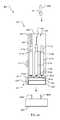
- FIG. 2depicts a front view of a multi-purpose handheld tool 201 in accordance with a preferred embodiment of the present application. It will be appreciated that tool 201 overcomes one or more of the above-listed problems commonly associated with conventional handheld tools.
- tool 201includes an elongated body 203 with an open end 205 providing access to a cavity 207 .
- the cavity 207houses a plurality of tool heads 209 , 211 , 213 connected to inner members 215 a , 215 b , 215 c telescopically engaged with outer members 217 a , 217 b , 217 c .
- the inner members 215 a - care in communication with driving screws 219 a , 219 b , 219 c in further communication with gears 221 a , 221 b , 221 c .
- the gears 221 a - care activated by a motor 223 in communication with a power source 225 and a control center 227 , the control center 227 having one or more switches 229 .
- tool 201is shown with a tool head 213 extended.
- the useractivates the motor 223 , causing a gear 221 c to turn and thereby raising tool head 213 above the open end 205 , allowing for use of tool head 213 .
- one of the unique features believed characteristic of the present applicationis the electrically operated extension of the tool heads 209 , 211 , 213 . It should be appreciated that this feature provides a multi-purpose hand held tool with improved functionality and convenience, by allowing for multiple tool heads to be combined into one tool and easily accessed.
- one contemplated set of tool headsincludes eating utensils such as forks, knives, and spoons.
- System 401includes an alternative embodiment of a multi-purpose tool 201 and a docking station 403 , wherein the multi-purpose tool 201 is configured to secure to one or more prongs 405 a , 405 b of the docking station 403 , and the docking station 403 is configured to charge the power source 225 .
- tool 201includes surgical tool heads including forceps 406 , an electrocautery tool 407 , and a scalpel 409 , wherein the scalpel 409 head is removable and replaceable by a connection means 411 such as a threaded connection.
- forceps 406 and electrocautery tool 407can be controlled by the control center 227 , wherein the power source 225 provides power to open and close the forceps 406 and activate the electrocautery tool 407 .
- tool 201can include a safety mechanism 413 to prevent undesired activation of the motor 223 .
- One contemplated safety mechanism 413is a button that prevents motor activation when unengaged.
- a second contemplated safety mechanism 413is a positional sensor, whereby the motor 223 can only be activated when tool 201 is held in a predetermined position.
- control center 227can be incorporated into a touch screen, whereby the user can extend tools, retract tools, and activate tools through the touch screen.
- additional featuressuch as automated selection of tool heads based on a gyroscopic sensor of tool position and/or the customization based on user data can be incorporated into tool 201 through the control center 227 .
- the control centercan collect user data, such as collect data when the user activates a specific tool.
- the control centercan be pre-programmed with the gyroscopic sensor, thereby allowing for automatic activation of one or more tools based on the data collected and the pre programming of the control center.
Landscapes
- Engineering & Computer Science (AREA)
- Mechanical Engineering (AREA)
- Theoretical Computer Science (AREA)
- Life Sciences & Earth Sciences (AREA)
- Forests & Forestry (AREA)
- Surgical Instruments (AREA)
Abstract
Description
Claims (14)
Priority Applications (1)
| Application Number | Priority Date | Filing Date | Title |
|---|---|---|---|
| US15/820,878US10471580B1 (en) | 2016-11-22 | 2017-11-22 | Multi-purpose tool |
Applications Claiming Priority (2)
| Application Number | Priority Date | Filing Date | Title |
|---|---|---|---|
| US201662425379P | 2016-11-22 | 2016-11-22 | |
| US15/820,878US10471580B1 (en) | 2016-11-22 | 2017-11-22 | Multi-purpose tool |
Publications (1)
| Publication Number | Publication Date |
|---|---|
| US10471580B1true US10471580B1 (en) | 2019-11-12 |
Family
ID=68466553
Family Applications (1)
| Application Number | Title | Priority Date | Filing Date |
|---|---|---|---|
| US15/820,878Expired - Fee RelatedUS10471580B1 (en) | 2016-11-22 | 2017-11-22 | Multi-purpose tool |
Country Status (1)
| Country | Link |
|---|---|
| US (1) | US10471580B1 (en) |
Citations (10)
| Publication number | Priority date | Publication date | Assignee | Title |
|---|---|---|---|---|
| US844603A (en)* | 1906-05-07 | 1907-02-19 | Claud Massey | Combination camping outfit. |
| US4922611A (en)* | 1989-07-26 | 1990-05-08 | Isy Levy | Knife/fork/spoon combination cutlery |
| US5511261A (en)* | 1994-09-21 | 1996-04-30 | Collins; Walter W. | Utility tool |
| US7089834B2 (en)* | 2004-04-07 | 2006-08-15 | Ryeson Corporation | Torque wrench with torque range indicator and system and method employing the same |
| US7373681B2 (en)* | 2003-10-17 | 2008-05-20 | Victorinox Ag | Pocket tool |
| US20100269648A1 (en)* | 2008-10-02 | 2010-10-28 | Fenstemaker Daniel P | Tool with interchangeable work heads |
| US20110271779A1 (en)* | 2009-02-16 | 2011-11-10 | Corcost Limited | Linear Actuator |
| US8397737B2 (en)* | 2008-06-16 | 2013-03-19 | Chad Arthur Evans | Linearly adjustable device |
| US20160089198A1 (en)* | 2013-05-31 | 2016-03-31 | Covidien Lp | Surgical device with an end-effector assembly and system for monitoring of tissue during a surgical procedure |
| US20170086496A1 (en)* | 2015-09-24 | 2017-03-30 | Lunatech, Llc | Electronic Vapor Device Multitool |
- 2017
- 2017-11-22USUS15/820,878patent/US10471580B1/ennot_activeExpired - Fee Related
Patent Citations (10)
| Publication number | Priority date | Publication date | Assignee | Title |
|---|---|---|---|---|
| US844603A (en)* | 1906-05-07 | 1907-02-19 | Claud Massey | Combination camping outfit. |
| US4922611A (en)* | 1989-07-26 | 1990-05-08 | Isy Levy | Knife/fork/spoon combination cutlery |
| US5511261A (en)* | 1994-09-21 | 1996-04-30 | Collins; Walter W. | Utility tool |
| US7373681B2 (en)* | 2003-10-17 | 2008-05-20 | Victorinox Ag | Pocket tool |
| US7089834B2 (en)* | 2004-04-07 | 2006-08-15 | Ryeson Corporation | Torque wrench with torque range indicator and system and method employing the same |
| US8397737B2 (en)* | 2008-06-16 | 2013-03-19 | Chad Arthur Evans | Linearly adjustable device |
| US20100269648A1 (en)* | 2008-10-02 | 2010-10-28 | Fenstemaker Daniel P | Tool with interchangeable work heads |
| US20110271779A1 (en)* | 2009-02-16 | 2011-11-10 | Corcost Limited | Linear Actuator |
| US20160089198A1 (en)* | 2013-05-31 | 2016-03-31 | Covidien Lp | Surgical device with an end-effector assembly and system for monitoring of tissue during a surgical procedure |
| US20170086496A1 (en)* | 2015-09-24 | 2017-03-30 | Lunatech, Llc | Electronic Vapor Device Multitool |
Similar Documents
| Publication | Publication Date | Title |
|---|---|---|
| EP3273767B1 (en) | Dual direction trimmer with self detection capability | |
| CN102961063B (en) | Lid and food processor for food processor | |
| US6910800B2 (en) | Blender having a top cover provided with a switch actuating block | |
| US7328633B2 (en) | Device for switching wrenching direction of a ratchet wheel of a ratchet tool | |
| US9975234B2 (en) | Pocket hand tool | |
| USRE38729E1 (en) | Combination of an electric-powered tool and an illuminating device received in the tool | |
| JP5995785B2 (en) | Brush cutter | |
| CN117136743A (en) | Gardening tool operating device | |
| US20090013477A1 (en) | Combination tool for electrical tasks | |
| EP3090613A1 (en) | Lawn mower and hand pushed power tool | |
| WO2013116303A1 (en) | Power tool | |
| US20050242598A1 (en) | Shovel capable of facilitating the operation of throwing shoveled objects off | |
| US8590163B1 (en) | Rotary cutter guard and safety light assembly | |
| KR102425403B1 (en) | device for tissue removal | |
| AU2020201022B2 (en) | System having a ground drilling device and an input device, method for controlling the operation of a ground drilling device and use of a ground drilling device | |
| US20060042559A1 (en) | Clipper for pet claws | |
| KR20110069825A (en) | Electronic piston stroke pipette | |
| US20210339408A1 (en) | Reciprocating Knife Assembly | |
| CN208540432U (en) | Gardening utensil | |
| CN108125705A (en) | A kind of foreskin Endo-GIA with insurance institution | |
| CN104768369B (en) | Power Tools with Status Indicators | |
| US10471580B1 (en) | Multi-purpose tool | |
| CN104257334B (en) | Drag and sweep all-in-one | |
| WO2016091715A1 (en) | Machine-tool operating device | |
| US9918815B1 (en) | Toothbrush system |
Legal Events
| Date | Code | Title | Description |
|---|---|---|---|
| FEPP | Fee payment procedure | Free format text:ENTITY STATUS SET TO UNDISCOUNTED (ORIGINAL EVENT CODE: BIG.); ENTITY STATUS OF PATENT OWNER: MICROENTITY | |
| FEPP | Fee payment procedure | Free format text:ENTITY STATUS SET TO UNDISCOUNTED (ORIGINAL EVENT CODE: BIG.); ENTITY STATUS OF PATENT OWNER: MICROENTITY Free format text:ENTITY STATUS SET TO MICRO (ORIGINAL EVENT CODE: MICR); ENTITY STATUS OF PATENT OWNER: MICROENTITY | |
| FEPP | Fee payment procedure | Free format text:ENTITY STATUS SET TO SMALL (ORIGINAL EVENT CODE: SMAL); ENTITY STATUS OF PATENT OWNER: MICROENTITY Free format text:ENTITY STATUS SET TO UNDISCOUNTED (ORIGINAL EVENT CODE: BIG.); ENTITY STATUS OF PATENT OWNER: MICROENTITY | |
| FEPP | Fee payment procedure | Free format text:ENTITY STATUS SET TO MICRO (ORIGINAL EVENT CODE: MICR); ENTITY STATUS OF PATENT OWNER: MICROENTITY | |
| FEPP | Fee payment procedure | Free format text:ENTITY STATUS SET TO MICRO (ORIGINAL EVENT CODE: MICR); ENTITY STATUS OF PATENT OWNER: MICROENTITY | |
| STCF | Information on status: patent grant | Free format text:PATENTED CASE | |
| FEPP | Fee payment procedure | Free format text:MAINTENANCE FEE REMINDER MAILED (ORIGINAL EVENT CODE: REM.); ENTITY STATUS OF PATENT OWNER: MICROENTITY | |
| LAPS | Lapse for failure to pay maintenance fees | Free format text:PATENT EXPIRED FOR FAILURE TO PAY MAINTENANCE FEES (ORIGINAL EVENT CODE: EXP.); ENTITY STATUS OF PATENT OWNER: MICROENTITY | |
| STCH | Information on status: patent discontinuation | Free format text:PATENT EXPIRED DUE TO NONPAYMENT OF MAINTENANCE FEES UNDER 37 CFR 1.362 | |
| FP | Lapsed due to failure to pay maintenance fee | Effective date:20231112 |