US10470757B2 - Suture passing instruments and methods - Google Patents
Suture passing instruments and methodsDownload PDFInfo
- Publication number
- US10470757B2 US10470757B2US15/479,143US201715479143AUS10470757B2US 10470757 B2US10470757 B2US 10470757B2US 201715479143 AUS201715479143 AUS 201715479143AUS 10470757 B2US10470757 B2US 10470757B2
- Authority
- US
- United States
- Prior art keywords
- needle
- curved needle
- actuator
- jaw
- curved
- Prior art date
- Legal status (The legal status is an assumption and is not a legal conclusion. Google has not performed a legal analysis and makes no representation as to the accuracy of the status listed.)
- Active, expires
Links
Images


Classifications
- A—HUMAN NECESSITIES
- A61—MEDICAL OR VETERINARY SCIENCE; HYGIENE
- A61B—DIAGNOSIS; SURGERY; IDENTIFICATION
- A61B17/00—Surgical instruments, devices or methods
- A61B17/04—Surgical instruments, devices or methods for suturing wounds; Holders or packages for needles or suture materials
- A61B17/0469—Suturing instruments for use in minimally invasive surgery, e.g. endoscopic surgery
- A—HUMAN NECESSITIES
- A61—MEDICAL OR VETERINARY SCIENCE; HYGIENE
- A61B—DIAGNOSIS; SURGERY; IDENTIFICATION
- A61B17/00—Surgical instruments, devices or methods
- A61B17/04—Surgical instruments, devices or methods for suturing wounds; Holders or packages for needles or suture materials
- A61B17/0482—Needle or suture guides
- A—HUMAN NECESSITIES
- A61—MEDICAL OR VETERINARY SCIENCE; HYGIENE
- A61B—DIAGNOSIS; SURGERY; IDENTIFICATION
- A61B17/00—Surgical instruments, devices or methods
- A61B17/04—Surgical instruments, devices or methods for suturing wounds; Holders or packages for needles or suture materials
- A61B17/06—Needles ; Sutures; Needle-suture combinations; Holders or packages for needles or suture materials
- A61B17/06066—Needles, e.g. needle tip configurations
- A—HUMAN NECESSITIES
- A61—MEDICAL OR VETERINARY SCIENCE; HYGIENE
- A61B—DIAGNOSIS; SURGERY; IDENTIFICATION
- A61B17/00—Surgical instruments, devices or methods
- A61B17/04—Surgical instruments, devices or methods for suturing wounds; Holders or packages for needles or suture materials
- A61B17/06—Needles ; Sutures; Needle-suture combinations; Holders or packages for needles or suture materials
- A61B17/062—Needle manipulators
- A—HUMAN NECESSITIES
- A61—MEDICAL OR VETERINARY SCIENCE; HYGIENE
- A61B—DIAGNOSIS; SURGERY; IDENTIFICATION
- A61B17/00—Surgical instruments, devices or methods
- A61B17/04—Surgical instruments, devices or methods for suturing wounds; Holders or packages for needles or suture materials
- A61B17/06—Needles ; Sutures; Needle-suture combinations; Holders or packages for needles or suture materials
- A61B17/06004—Means for attaching suture to needle
- A61B2017/06009—Means for attaching suture to needle having additional means for releasably clamping the suture to the needle, e.g. actuating rod slideable within the needle
- A—HUMAN NECESSITIES
- A61—MEDICAL OR VETERINARY SCIENCE; HYGIENE
- A61B—DIAGNOSIS; SURGERY; IDENTIFICATION
- A61B17/00—Surgical instruments, devices or methods
- A61B17/04—Surgical instruments, devices or methods for suturing wounds; Holders or packages for needles or suture materials
- A61B17/06—Needles ; Sutures; Needle-suture combinations; Holders or packages for needles or suture materials
- A61B17/06004—Means for attaching suture to needle
- A61B2017/06042—Means for attaching suture to needle located close to needle tip
- A—HUMAN NECESSITIES
- A61—MEDICAL OR VETERINARY SCIENCE; HYGIENE
- A61B—DIAGNOSIS; SURGERY; IDENTIFICATION
- A61B17/00—Surgical instruments, devices or methods
- A61B17/04—Surgical instruments, devices or methods for suturing wounds; Holders or packages for needles or suture materials
- A61B17/06—Needles ; Sutures; Needle-suture combinations; Holders or packages for needles or suture materials
- A61B17/06066—Needles, e.g. needle tip configurations
- A61B2017/0608—J-shaped
- A—HUMAN NECESSITIES
- A61—MEDICAL OR VETERINARY SCIENCE; HYGIENE
- A61B—DIAGNOSIS; SURGERY; IDENTIFICATION
- A61B17/00—Surgical instruments, devices or methods
- A61B17/28—Surgical forceps
- A61B17/29—Forceps for use in minimally invasive surgery
- A61B17/2909—Handles
- A61B2017/2925—Pistol grips
- A—HUMAN NECESSITIES
- A61—MEDICAL OR VETERINARY SCIENCE; HYGIENE
- A61B—DIAGNOSIS; SURGERY; IDENTIFICATION
- A61B17/00—Surgical instruments, devices or methods
- A61B17/28—Surgical forceps
- A61B17/29—Forceps for use in minimally invasive surgery
- A61B2017/2946—Locking means
Definitions
- the present inventionincludes surgical instruments that are configured to secure tissue and pass a needle through the secured tissue where the needle is equipped to deliver a suture through the tissue.
- suture passing instrumentsare used for tissue repair procedures.
- Suturing devicesare commonly used for open and endoscopic surgical procedures that require the use of a suture to ligate, join, re-attach tendon to bone, or otherwise secure adjoining tissue. Many such suturing devices grasp the tissue with a jaw assembly and pass the suture through the tissue using a needle that undergoes deformation either when loaded into the device, or upon exiting the device. Many of these devices rely on super-elastic needles that must be replaced.
- a suture passing instrumentthat may be operated in the manner similar to conventional suture passing devices but employ a pre-curved needle that does not experience deformation within the suturing device or during deployment of the suturing device. Elimination of the deformation of the needle can allow for a device with a fixed needle, that can optionally be reusable, which can result in a cost savings.
- the present disclosureincludes suture passing instruments having a curved needle that does not experience deformation within the suture passing device and during deployment.
- a suturing devicecan provide a fixed needle rather than a disposable or replaceable needle.
- the suture passing devicecomprises a shaft having a far portion and a near portion; a handle assembly located at the near end of the shaft and comprising a needle actuator moveably coupled to a handle portion, a trigger lever moveably coupled to the handle portion, the handle portion coupled to the near end of the shaft; a jaw assembly comprising an actuating jaw moveably coupled to a fixed jaw, the fixed jaw located at the far portion of the shaft, where actuation of the trigger lever moves the actuating jaw relative to the fixed jaw to open and close the jaw assembly; a curved needle nested within the fixed jaw and slidable within a curved track of the fixed jaw, where a curvature of the curved needle and a curvature of the track are matched to permit movement of the curved needle through the curved track in without being deformed, the curved needle having a suture carrying slot at a distal portion allowing for loading of a suture external to the shaft; and a needle linkage having a first end coupled to a proximal section
- the suture passing devicecan also include a variation the fixed jaw comprises an opening at a distal end exposing the suture carrying slot for loading of the suture external to the shaft. This slot may be through the center or side of the lower fixed jaw.
- the suture passing device ofcan comprise an actuating jaw having an opening at a distal end to further expose the suture carrying slot when the jaw assembly is closed.
- the suture passing devicefurther comprises a jaw linkage located within the shaft and having a first end and a second end, the first end of the jaw linkage engaged with the actuating jaw, the second end of the jaw linkage engaged with the trigger lever, such that movement of the trigger lever relative to the handle portion causes movement of the jaw linkage causing movement of the actuating jaw relative to the fixed jaw.
- Variations of the suture passing devicecan include a trigger lever that comprises a first actuator portion pivotally coupled to the handle portion and a second locking portion pivotally coupled to the first actuator portion, where the second locking portion comprises a trigger locking surface moveably engaged with a handle locking surface, such that when engaged, the trigger locking surface and handle locking surface locks the trigger lever in place to lock the jaw assembly in place.
- the suture passing devicecan include a second locking portion that is spring biased against the first actuator portion, and where relative movement between the first actuator portion and the second locking portion causes disengagement of the trigger locking surface from the handle locking surface to release the jaw assembly.
- the devicecan be used with or without a ratchet lock configuration.
- the pivot jointcomprises a bore in the proximal section of the curved needle and a slot in the first end of the needle linkage.
- variations of the devicecan comprise a curved needle and needle linkage that are continuous and the pivot joint comprises a living hinge between the curved needle and needle linkage.
- the suture passing device described hereincan include a needle actuator that is spring biased against the handle portion to cause the curved needle to remain within the curved track until a force is applied to the needle actuator.
- Variations of the devicecan also include a locking mechanism to prevent motion of the needle in the locked position.
- the trigger levercan be spring biased against the handle portion to cause the jaw assembly to remain open until a force is applied to the trigger lever.
- Variations of the suture passing devicesinclude a needle actuator that is moveably coupled to the handle portion at an end of the handle portion opposite to the shaft.
- FIG. 1illustrates an example of a suture passing device having an elongate shaft with a handle assembly located at a near or proximal end of the shaft and a jaw assembly located at a far or distal end of the shaft.
- FIG. 2Aillustrates a magnified view of the jaw assembly of FIG. 1 .
- FIG. 2Billustrates a top view of the fixed jaw (where the upper or actuating jaw is omitted for purposes of illustration).
- FIG. 2Cillustrates a needle extending from the jaw assembly in an actuated position when the actuating jaw is clamped against the fixed jaw at the end of the shaft.
- FIG. 2Dillustrates a top view of the fixed jaw with a side opening to load a suture (where the upper or actuating jaw is omitted for purposes of illustration).
- FIG. 3Ashows an example of a needle coupled to a needle linkage at a first end of the needle linkage and second end of the linkage coupled to a portion of the handle assembly.
- FIG. 3Billustrates a magnified section 3 B of FIG. 3A .
- FIG. 3Cillustrates the needle coupled to the needle linkage at a pivot joint.
- FIG. 3Dillustrates a needle freely pivoting relative to a pivot joint.
- FIG. 4Aillustrates a cross sectional view of the jaw assembly in an open position.
- FIG. 4Billustrates the lower jaw without the needle, link member, or upper jaw for purposes of illustrating the needle track.
- FIG. 4Cillustrates the link member advancing a needle partially through the track of the lower jaw.
- FIG. 4Dillustrates a cross section of the articulating jaw and jaw link member to illustrate a passage extending through the jaw link member.
- FIGS. 5A to 5Dillustrate a cross sectional view of the jaw assembly to show the movement of the actuating jaw and needle.
- FIGS. 6A to 6Cillustrate actuation of an example of a handle assembly to drive the suture passing device.
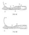
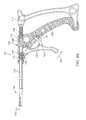
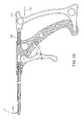
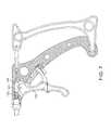
- FIGS. 7, 8A, and 8Bshow alternate variations of suture passing devices.
- FIG. 1illustrates a first example of a suture passing device 100 having an elongate shaft 102 with a handle assembly 104 located at a near or proximal end of the shaft 102 and a jaw assembly 150 located at a far or distal end of the shaft 102 .
- the handle assembly 104 shown in FIG. 1includes a handle portion 106 that is fixedly attached to the shaft 102 .
- Alternate variationscan include rotational coupling between the shaft 102 and handle portion 106 . Where such rotational coupling can include ratchetable configuration and/or a freely rotational coupling with or without the ability to lock the two components together.
- the handle assembly 104 of the present inventioncan comprise any handle configuration used with known suture passing devices or related technology.
- the handle portion 106 of the variation shown in FIG. 1includes a trigger lever 108 moveable relative to the handle portion 106 , which actuates the jaw assembly 150 .
- the handle assembly 104can also include a separate needle actuator 110 that is moveably coupled to the handle portion 106 , where movement of the needle actuator 110 drives a needle element as discussed below.
- the suture passing device 100can also include a port 112 that aids in cleaning and decontamination of the device.
- the port 112can permit fluids to pass through the shaft 102 and through the jaw assembly 150 for cleaning and sterilizing.
- the shaftcan be decoupled from the assembly to permit a thorough cleaning.
- FIG. 1also shows the jaw assembly 150 comprising a fixed jaw 152 and an actuating jaw 154 that is configured to pivot relative to the fixed jaw 152 to secure tissue therebetween.
- FIG. 2Aillustrates a magnified view of the jaw assembly 150 of FIG. 1 where the jaw assembly 150 is in an open configuration.
- the actuating jaw 154can include a surface 156 configured to close against the fixed jaw 152 to secure tissue therebetween. This surface 156 can include ridges, or other protrusion to improve securing of the tissue.
- the actuating jaw 154also includes a channel 158 that allows for delivery of the needle and suture (not shown in FIG. 2A ) through the clamped jaw assembly 150 .
- the channel 158is positioned in line with a track 164 of the lower or fixed jaw 152 so as to not impede movement of the suture and needle when the needle is actuated.
- FIG. 2Billustrates a top view of the fixed jaw 152 (where the upper or actuating jaw is omitted for purposes of illustration).
- a needle 162is nested within a track 164 of the fixed jaw 152 .
- the needle 162comprises a curved shape (as discussed below) and is coupled to a needle linkage 168 . Where the opposite end of the needle linkage 168 couples to an actuator on the handle portion (not shown).
- the fixed jaw 152includes a suture channel 166 that permits loading of the suture onto the needle 162 .
- the needle 162includes a suture groove 168 that nests a suture when the suture is advanced through the suture channel 166 onto the needle 162 .
- Alternate variationscan include sutures being loaded onto a tip of the needle itself.
- the devicecan allow for side-loading of a suture through a slot in fixed jaw 152 located on a side of the device and as shown in FIG. 2D .
- FIG. 2Cillustrates a needle 162 extending from the jaw assembly 150 in an actuated position when the actuating jaw 154 is clamped against the fixed jaw 152 at the end of the shaft 102 .
- this example of the deviceincludes a needle 162 comprising a flat construction.
- additional variations of the devicescan include needles having other cross-sectional geometries (e.g., circular, oval, hollow, triangular, etc.).
- FIG. 3Ashows an example of a needle 162 coupled to a needle linkage 168 at a first end of the needle linkage 168 and second end of the linkage 168 coupled to a portion 114 of the handle assembly 104 .
- the needle linkage 168can be directly coupled to the needle actuator of the handle assembly.
- the coupling portion 114 of the handle assemblyis pivotally affixed to the needle actuator (not shown) via a pivot connection at location 116 .
- a springshown in FIG. 1
- FIG. 3Billustrates a magnified section 3 B of FIG.
- the needle linkage 168can include one or more features to allow axial translation of the needle actuator to drive the needle linkage 168 within the shaft 102 to actuate the needle 162 from the jaw assembly.
- the needle linkage 168comprises a tapered portion 174 joining a narrow distal region 172 of the linkage 168 to a larger proximal region 176 . As discussed below, this tapered portion 174 allows for the needle linkage 168 to move within the device without interfering with other components of the device.
- FIG. 3Cillustrates the needle 162 coupled to the needle linkage 168 at a pivot joint 180 .
- the pivot joint 180 illustratedis one example of a joint that joins two separate components, a needle 162 and the needle linkage 168 . While the illustrated variation shows the needle a member that rests within a slot of the needle linkage, alternate variations of the device can include any number of configurations that couple two separate components. Such a configuration allows the needle to be fabricated from a preferred material, such as an alloy or stainless steel.
- the needle 162comprises a curved configuration that nests within a track having a matching curved configuration therefore there is no deformation of the needle and/or the needle linkage.
- suture passing deviceThis permits variations of the suture passing device to include a needle fabricated from a non-shape memory material where the pre-curved needle resides within the suture passing device and does not experience material fatigue from repeated deformation. Such a construction allows for a permanent needle within the suture passing device as opposed to a disposable needle.
- a variation of the deviceincludes a non-deformable, high strength, and/or rigid needle fabricated from a hardened material. Since the needle is pre-curved and does not undergo deformation when in the device, the hardened needle can be driven through thick, fibrous, calcified, or other difficult tissue that would cause deformation of the conventional type of needles (such as shape memory or Nitinol materials) that are often used in suture passing devices.
- the needle materialcomprises a hardened stainless steel alloy with a UTS (ultimate tensile strength of 230,000 PSI.
- the stainless steelis handed and then is shaped through an electrical discharge machining (EDM) process that cuts or forms the hardened material into a naturally curved state that remains in a permanently non-deformed curved state.
- EDMelectrical discharge machining
- This materialcombined with a larger cross sectional surface (such as the rectangular cross-sectional profile shown in the figures) provides the ability of the device to apply significant force to the needle when compared to conventional deformable needles (e.g., Nitinol needles).
- the pre-curved needlewas fabricated from a custom 455 ® Stainless steel with a hardness of H900 provided by Carpenter Technology Corporation (PA).
- the pivot joint 180 coupling the needle 162 and the needle linkage 168allows the needle to freely pivot relative to the needle linkage 168 as shown in FIG. 3D .
- This rotational movementallows the needle to extend through the track of the slot assembly and through the jaw being advanced by the needle linkage 168 , which moves in a linear direction within the device.
- the pivot joint 180is illustrated to have an open end, variations of the invention can include pivot joints that are closed or covered while allowing the curved needle to pivot relative to the needle linkage 168 .
- FIG. 4Aillustrates a cross sectional view of the jaw assembly 150 in an open position to illustrate the curved needle track 164 of the fixed jaw 152 to better illustrate the needle track 164 within the fixed jaw 152 .
- the actuating jaw 154is driven by a link member 120 that is coupled to a trigger lever (not shown) on the handle assembly.
- the movement of the needle link 168can occur independently of the actuating jaw linkage 120 .
- the link member 168can extend through a passage 122 (see FIG. 4D ) of the jaw linkage 120 .
- FIG. 4Billustrates the lower jaw 152 without the needle, link member, or upper jaw for purposes of illustrating the needle track 164 .
- the needle track 164can allow retention of the needle while permitting unimpeded movement of the link member 168 . This movement is illustrated in FIG. 4C where the link member 168 advances a needle 162 partially through the track 164 of the lower jaw 152 and where the track 164 provides clearance for the link member 168 as the pivot joint allows the link member 168 to follow the needle 162 without deformation or entering the track 164 .
- FIG. 4Dillustrates a cross section of the articulating jaw 154 and jaw link member 120 to illustrate a passage extending through the jaw link member 120 .
- the passagealso extends through a coupling portion 124 on the proximal or near end of the jaw link member 120 .
- the distal or far end of the link member 120comprises a relief cut 126 that allows the needle link member 168 to follow the needle through the arc of the needle track 164 .
- FIGS. 5A to 5Dillustrate a cross sectional view of the jaw assembly 150 to show the movement of the actuating jaw 154 and needle 162 . While the illustrated example shows a fixed lower jaw 152 as containing the needle 162 , alternate variations of the device can include both jaws being moveable or just the lower jaw being moveable. Furthermore, in alternate variations of the devices, the curved needle can be positioned in the upper jaw. For purposes of illustration, the actuating jaw 154 is omitted from FIGS. 5C and 5D .
- FIG. 5Aillustrates a jaw assembly 150 in an open position. Movement of jaw linkage 120 in a distal/far direction causes closure of the actuating jaw 154 against the fixed jaw 152 (as shown in FIG. 5B ) without moving the needle linkage 168 or needle 162 that is nested within the needle track in its natural curved state.
- FIG. 5Cillustrates movement of the needle linkage 168 in a distal direction, which drives the needle 162 through the needle track 164 and out of the lower jaw 152 . As shown, the pivot joint 180 allows the needle linkage 168 to follow movement of the needle 162 through the track 164 without deforming.
- FIG. 5Dshows the needle link 168 moved in a distal most position to fully advance the needle 162 from the jaw assembly. Again, the needle link 168 moves to follow the arc of the curved needle track 164 and moves towards a top of the lower jaw 152 . As shown, the pre-curved needle does not undergo deformation at any point during its movement.
- the jaw assemblycan further include any number of stops on the needle, needle link, and/or jaw to prevent advancement of the needle 162 or needle linkages 168 .
- FIGS. 6A to 6Cillustrate actuation of an example of a handle assembly 104 to drive the suture passing device.
- the structure shown in these figuresis meant to illustrate one possible variation of the inventive suture advancing device.
- any number of handle assembliesis within the scope of this disclosure and claims.
- FIG. 6Aillustrates a trigger lever 108 that is coupled, indirectly, to a first spring member 136 .
- the trigger lever 108engages a coupling portion 124 of the jaw linkage, which carries a first spring 136 .
- the first spring 136biases the jaw linkage 120 away from the jaw assembly 150 such that the jaw assembly 150 is naturally biased in an open position (as shown in FIG. 1 ).
- the needle actuator 110is coupled to a coupling portion 114 of the needle linkage 168 with a second spring member 138 biasing the needle actuator 110 away from the jaw assembly 150 to maintain the needle within the needle track in an initial position.
- the first spring 136is configured a lower spring constant (or is less stiff) than the second needle spring 138 . This balancing of springs allow a user to position the device appropriately and then squeeze the trigger lever 108 while applying force on the needle actuator 110 . Because the first spring 136 is less stiff than the second spring 138 , the trigger lever 108 pivots at its coupling point and moves in direction 140 to drive the jaw linkage 120 and 124 towards the jaw assembly 150 .
- a variation of the device 100can include a trigger locking surface 128 that engages a handle 130 locking surface 130 coupled to a handle portion 106 . Such surfaces can comprise a ratchet and pawl system or detent system. In the illustrated variation, and as discussed below, the trigger locking surface 128 can be spring biased to remain against the handle locking portion 130 such that movement of trigger in direction 140 is prevented from reversing while the trigger locking surface 128 remains engaged with the handle locking surface 130 .
- FIG. 6Cillustrates the device after the needle actuator 110 returns to the normal position where the needle is seated within the needle track and after the suturing procedure is completed.
- This variation of the device 100includes a two part trigger lever.
- a first part 108 of the trigger leveractuates the jaw assembly as described above.
- the second part 134 of the trigger assemblyis spring biased by trigger spring 132 to maintain trigger locking surface 128 in engagement with the handle 130 locking surface 130 .
- the operatormoves the second part 134 of the trigger lever to compress the trigger spring 132 .
- This compressioncauses movement of the trigger locking surface 128 away from the handle locking surface 130 in direction 149 .
- the disengagement of the locking surfaces 128 and 130allows the jaw spring 136 to move the jaw linkage 120 and coupling portion 124 away from clamp assembly 150 causing the jaw assembly to open.
- FIG. 7illustrates another variation of a suture passing device as discussed above.
- the trigger lever 108 that drives the jaw assemblyis configured to increase a clamping force of the jaw assembly (not shown in FIG. 7 ).
- the pivot 109 of the trigger lever 108is moved closer to the coupling portion 124 of the jaw linkage 120 . This permits the user to apply an increased force to close the jaw assembly, which may be necessary when driving a rigid curved needle through fibrous or other hardened tissue material.
- FIGS. 8A and 8Brepresent additional variations of jaw structures for use with the concepts disclosed herein.
- FIG. 8Aillustrates a device 200 useful for glenoid repair procedures in which the fixed jaw 202 comprises a curved sharp tip adjacent to a grasping jaw 204 .
- FIG. 8Billustrates a cross sectional view of a similar device where a curved needle 206 and linkage 208 reside within the curved jaw 202 .
Landscapes
- Health & Medical Sciences (AREA)
- Life Sciences & Earth Sciences (AREA)
- Surgery (AREA)
- Heart & Thoracic Surgery (AREA)
- Engineering & Computer Science (AREA)
- Biomedical Technology (AREA)
- Nuclear Medicine, Radiotherapy & Molecular Imaging (AREA)
- Medical Informatics (AREA)
- Molecular Biology (AREA)
- Animal Behavior & Ethology (AREA)
- General Health & Medical Sciences (AREA)
- Public Health (AREA)
- Veterinary Medicine (AREA)
- Surgical Instruments (AREA)
Abstract
Description
Claims (20)
Priority Applications (1)
| Application Number | Priority Date | Filing Date | Title |
|---|---|---|---|
| US15/479,143US10470757B2 (en) | 2016-03-02 | 2017-04-04 | Suture passing instruments and methods |
Applications Claiming Priority (4)
| Application Number | Priority Date | Filing Date | Title |
|---|---|---|---|
| US201662302190P | 2016-03-02 | 2016-03-02 | |
| US15/072,243US9439647B1 (en) | 2016-03-02 | 2016-03-16 | Suture passing instruments and methods |
| US15/261,521US9668726B1 (en) | 2016-03-02 | 2016-09-09 | Suture passing instruments and methods |
| US15/479,143US10470757B2 (en) | 2016-03-02 | 2017-04-04 | Suture passing instruments and methods |
Related Parent Applications (1)
| Application Number | Title | Priority Date | Filing Date |
|---|---|---|---|
| US15/261,521ContinuationUS9668726B1 (en) | 2016-03-02 | 2016-09-09 | Suture passing instruments and methods |
Publications (2)
| Publication Number | Publication Date |
|---|---|
| US20170333030A1 US20170333030A1 (en) | 2017-11-23 |
| US10470757B2true US10470757B2 (en) | 2019-11-12 |
Family
ID=56881154
Family Applications (3)
| Application Number | Title | Priority Date | Filing Date |
|---|---|---|---|
| US15/072,243ActiveUS9439647B1 (en) | 2016-03-02 | 2016-03-16 | Suture passing instruments and methods |
| US15/261,521ActiveUS9668726B1 (en) | 2016-03-02 | 2016-09-09 | Suture passing instruments and methods |
| US15/479,143Active2036-12-16US10470757B2 (en) | 2016-03-02 | 2017-04-04 | Suture passing instruments and methods |
Family Applications Before (2)
| Application Number | Title | Priority Date | Filing Date |
|---|---|---|---|
| US15/072,243ActiveUS9439647B1 (en) | 2016-03-02 | 2016-03-16 | Suture passing instruments and methods |
| US15/261,521ActiveUS9668726B1 (en) | 2016-03-02 | 2016-09-09 | Suture passing instruments and methods |
Country Status (2)
| Country | Link |
|---|---|
| US (3) | US9439647B1 (en) |
| WO (1) | WO2017151277A1 (en) |
Families Citing this family (13)
| Publication number | Priority date | Publication date | Assignee | Title |
|---|---|---|---|---|
| US11452521B2 (en) | 2017-03-29 | 2022-09-27 | Smith & Nephew, Inc. | Angled suture passer and method of use thereof |
| EP3784146B1 (en)* | 2018-04-27 | 2024-01-10 | Ceterix Orthopaedics, Inc. | Suture passer devices |
| WO2020081651A1 (en) | 2018-10-16 | 2020-04-23 | Activ Surgical, Inc. | Autonomous methods and systems for tying surgical knots |
| CA3120184A1 (en) | 2018-11-15 | 2020-05-22 | Applied Medical Resources Corporation | Laparoscopic grasper with force-limiting grasping mechanism |
| WO2020140056A1 (en) | 2018-12-28 | 2020-07-02 | Activ Surgical, Inc. | Systems and methods to optimize reachability, workspace, and dexterity in minimally invasive surgery |
| WO2020140042A1 (en) | 2018-12-28 | 2020-07-02 | Activ Surgical, Inc. | User interface elements for orientation of remote camera during surgery |
| WO2020214821A1 (en) | 2019-04-19 | 2020-10-22 | Activ Surgical, Inc. | Systems and methods for trocar kinematics |
| CN111481249B (en)* | 2020-04-24 | 2021-03-26 | 复旦大学附属中山医院厦门医院 | Blood vessel suturing device |
| CN112826658A (en)* | 2021-01-26 | 2021-05-25 | 广东省第二人民医院(广东省卫生应急医院) | Needle tweezers |
| JP7715370B2 (en)* | 2021-01-26 | 2025-07-30 | 隆士 新田 | surgical instruments |
| CN114010270A (en)* | 2021-11-08 | 2022-02-08 | 温州医科大学附属第二医院(温州医科大学附属育英儿童医院) | Hook scissors |
| EP4472524A4 (en) | 2022-01-31 | 2025-10-01 | William H Simon | SURGICAL DEVICES AND METHODS FOR ACHILLES TENDON REPAIR |
| US12433583B1 (en)* | 2024-05-31 | 2025-10-07 | Integrity Medical Services Inc. | Suture passer devices, systems, and methods |
Citations (107)
| Publication number | Priority date | Publication date | Assignee | Title |
|---|---|---|---|---|
| US1822330A (en) | 1930-01-13 | 1931-09-08 | Ainslie George | Suturing instrument |
| US2748773A (en) | 1954-06-24 | 1956-06-05 | Jr Edward Vacheresse | Ligating hemostat |
| US3470875A (en) | 1966-10-06 | 1969-10-07 | Alfred A Johnson | Surgical clamping and suturing instrument |
| US3807407A (en) | 1971-06-07 | 1974-04-30 | E Schweizer | Suture applicator |
| US3842840A (en) | 1973-05-07 | 1974-10-22 | E Schweizer | Suture applicator |
| US3901244A (en) | 1973-05-07 | 1975-08-26 | Edward E Schweizer | Suture cartridge |
| US3946740A (en) | 1974-10-15 | 1976-03-30 | Bassett John W | Suturing device |
| US4569131A (en) | 1983-06-01 | 1986-02-11 | Richard Wolf Gmbh | Tool having a handle with an interchangeable insert portion |
| US4890615A (en) | 1987-11-05 | 1990-01-02 | Concept, Inc. | Arthroscopic suturing instrument |
| US4957498A (en) | 1987-11-05 | 1990-09-18 | Concept, Inc. | Suturing instrument |
| US5176702A (en) | 1991-04-04 | 1993-01-05 | Symbiosis Corporation | Ratchet locking mechanism for surgical instruments |
| US5254126A (en) | 1992-06-24 | 1993-10-19 | Ethicon, Inc. | Endoscopic suture punch |
| DE4235602A1 (en) | 1992-10-22 | 1994-04-28 | Oktay Dr Med Sevinc | Laparoscopic suture preforming instrument - has two jaws, one forked and other having inclined hole to hold needle head and also having recess to accommodate needle |
| US5312422A (en) | 1992-07-16 | 1994-05-17 | Linvatec Corporation | Endoscopic suturing needle |
| US5314424A (en) | 1992-04-06 | 1994-05-24 | United States Surgical Corporation | Surgical instrument locking mechanism |
| US5387227A (en) | 1992-09-10 | 1995-02-07 | Grice; O. Drew | Method for use of a laparo-suture needle |
| US5391174A (en) | 1991-11-29 | 1995-02-21 | Weston; Peter V. | Endoscopic needle holders |
| DE4334746A1 (en) | 1993-10-12 | 1995-04-13 | Lutz Kothe | Surgical instrument |
| US5431666A (en) | 1994-02-24 | 1995-07-11 | Lasersurge, Inc. | Surgical suture instrument |
| US5437681A (en)* | 1994-01-13 | 1995-08-01 | Suturtek Inc. | Suturing instrument with thread management |
| US5454823A (en) | 1991-09-30 | 1995-10-03 | Richardson; Philip | Suturing apparatus |
| US5483952A (en) | 1991-09-26 | 1996-01-16 | United States Surgical Corporation | Handle for surgical instruments |
| US5499998A (en) | 1993-09-14 | 1996-03-19 | Microsurge, Inc. | Endoscoptic surgical instrument with guided jaws and ratchet control |
| US5522820A (en) | 1993-01-15 | 1996-06-04 | Arthrotech | Method and apparatus for suturing tissue |
| WO1996039948A1 (en) | 1995-06-07 | 1996-12-19 | Smith & Nephew, Inc. | Suture passing forceps |
| US5613977A (en) | 1992-07-22 | 1997-03-25 | Friatec Ag Keramik-Und-Kunstoffwerke | Gripping and/or cutting instrument for endoscopic purposes |
| WO1997010756A1 (en) | 1995-09-22 | 1997-03-27 | Inbae Yoon | Combined tissue clamping and suturing instrument |
| US5626608A (en) | 1996-03-29 | 1997-05-06 | United States Surgical Corporation | Surgical instrument having locking handle |
| US5814054A (en) | 1996-09-23 | 1998-09-29 | Symbiosis Corporation | Automatic needle-passer suturing instrument |
| US5824009A (en) | 1995-12-06 | 1998-10-20 | Kabushiki Kaisha Matsutani Seisakusho | Guide instrument for a medical needle with thread |
| US5980538A (en) | 1997-09-09 | 1999-11-09 | Werner Fuchs | Surgical suturing instrument |
| US6077286A (en) | 1996-05-07 | 2000-06-20 | Karl Storz Gmbh & Co. Kg | Instrument with a bendable handle |
| US6117158A (en) | 1999-07-07 | 2000-09-12 | Ethicon Endo-Surgery, Inc. | Ratchet release mechanism for hand held instruments |
| US6245079B1 (en) | 1995-08-24 | 2001-06-12 | Sutura, Inc. | Suturing device and method for sealing an opening in a blood vessel or other biological structure |
| US6299624B1 (en) | 1999-05-27 | 2001-10-09 | Karl Storz Gmbh & Co. Kg | Handle for a medical instrument |
| US20020065526A1 (en) | 2000-11-28 | 2002-05-30 | Ran Oren | Suturing instrument and method |
| US20020103493A1 (en) | 2001-01-26 | 2002-08-01 | Raymond Thal | Surgical suture passer |
| US20020138084A1 (en) | 2001-03-23 | 2002-09-26 | Weber Robert M. | Arthroscopic suture passing instrument |
| US20020147456A1 (en) | 2001-02-26 | 2002-10-10 | Diduch David R. | Superelastic suture passing devices and methods |
| US6527785B2 (en) | 1999-08-03 | 2003-03-04 | Onux Medical, Inc. | Surgical suturing instrument and method of use |
| US6533795B1 (en) | 2000-04-11 | 2003-03-18 | Opus Medical, Inc | Dual function suturing apparatus and method |
| US20030083695A1 (en) | 2001-08-06 | 2003-05-01 | Morris John K. | Compact suture punch with malleable needle |
| EP0812572B1 (en) | 1996-06-10 | 2003-08-13 | Ethicon Endo-Surgery, Inc. | Suture assist device |
| US20030220659A1 (en) | 2002-02-04 | 2003-11-27 | Reinhold Schmieding | Knot pusher and suture retriever |
| US20030220657A1 (en) | 2001-05-23 | 2003-11-27 | Ronald Adams | Endoluminal fundoplication device and related method |
| US20030233106A1 (en) | 2002-05-15 | 2003-12-18 | Dreyfuss Peter J. | Suture passing instrument |
| US20040015177A1 (en) | 2002-07-22 | 2004-01-22 | Scimed Life Systems, Inc. | Placing sutures |
| US6770084B1 (en) | 2002-06-26 | 2004-08-03 | Opus Medical, Inc. | Suture capture device |
| US20040249394A1 (en) | 2001-08-06 | 2004-12-09 | Arthrex, Inc. | Compact suture punch with malleable needle |
| US20040260314A1 (en) | 2003-06-23 | 2004-12-23 | Lizardi Jose E. | Tissue grasper/suture passer instrument |
| US20050085832A1 (en) | 1998-08-27 | 2005-04-21 | Dvl Acquisitions, Sub, Inc. | Surgical suturing instrument and method of use |
| US6921408B2 (en) | 2002-03-12 | 2005-07-26 | Lsi Solutions, Inc. | Apparatus for sewing tissue and method of use |
| US20050222597A1 (en) | 2003-07-15 | 2005-10-06 | Frank Timothy G | Medical gripping and/or cutting instrument |
| US20050234479A1 (en) | 2002-05-22 | 2005-10-20 | Orthopaedic Biosystems Ltd., Inc. A Delaware Corporation | Suture passing surgical instrument |
| US20050245932A1 (en) | 2004-04-16 | 2005-11-03 | Fanton Gary S | Apparatus and methods for securing tissue to bone |
| US20050288690A1 (en) | 2004-06-16 | 2005-12-29 | Bourque Bernard J | Suture passing |
| US7004951B2 (en) | 2001-10-04 | 2006-02-28 | Gibbens Group Llc | Cycling suturing and knot-tying device |
| EP1067872B1 (en) | 1998-03-20 | 2006-03-01 | Boston Scientific Limited | Endoscopic suture system |
| US7011668B2 (en) | 2001-07-23 | 2006-03-14 | Dvl Acquistion Sub, Inc. | Surgical suturing instrument and method of use |
| US7037315B2 (en) | 2001-09-14 | 2006-05-02 | Dvl Aquisition Sub, Inc. | Surgical suturing instrument and method of use |
| US7063715B2 (en) | 2002-07-11 | 2006-06-20 | Olympus Corporation | Endoscopic suture apparatus |
| USD523554S1 (en) | 2002-09-25 | 2006-06-20 | Depuy Mitek, Inc. | Suture needle |
| US7131980B1 (en) | 2001-01-18 | 2006-11-07 | Dvl Acquisitions Sub, Inc. | Surgical suturing instrument and method of use |
| US7131979B2 (en) | 2002-05-17 | 2006-11-07 | Dvl Acquisition Sub, Inc. | Surgical suturing instrument and method of use |
| US7131978B2 (en) | 2001-12-11 | 2006-11-07 | Dvl Acquisition Sub, Inc. | Surgical suturing instrument and method of use |
| US20060271073A1 (en) | 2005-05-26 | 2006-11-30 | Usgi Medical Inc. | Methods and apparatus for securing and deploying tissue anchors |
| US20060271074A1 (en) | 2005-05-26 | 2006-11-30 | Ewers Richard C | Methods and apparatus for securing and deploying tissue anchors |
| US20060282098A1 (en) | 2005-06-13 | 2006-12-14 | Shelton Frederick E Iv | Surgical suturing apparatus with detachable handle |
| US20070016248A1 (en) | 2005-06-14 | 2007-01-18 | Alfred Cuschieri | Medical gripping and/or cutting instrument |
| US7232448B2 (en) | 2004-06-17 | 2007-06-19 | Ethicon, Inc. - Usa | Minimally invasive stitching device |
| US20070225735A1 (en) | 2006-03-21 | 2007-09-27 | Stone Kevin T | Method and apparatus for passing a suture |
| US20070255317A1 (en) | 2006-03-22 | 2007-11-01 | Fanton Gary S | Suture passer devices and uses thereof |
| US20070270885A1 (en) | 2001-10-01 | 2007-11-22 | Depuy Mitek, Inc., A Massachusetts Corporation | Suturing apparatus and method |
| US20080027468A1 (en) | 2006-07-27 | 2008-01-31 | Axya Medical Inc. | Suture needle, suture needle/suture assembly and suture passer device |
| US7338513B2 (en) | 2003-10-30 | 2008-03-04 | Cambridge Endoscopic Devices, Inc. | Surgical instrument |
| US7377926B2 (en) | 2001-10-01 | 2008-05-27 | Depuy Mitek, Inc. | Suturing apparatus and method |
| US7407505B2 (en) | 2004-01-14 | 2008-08-05 | Lsi Solutions, Inc. | Running stitch suturing device |
| US20080208221A1 (en) | 2007-02-13 | 2008-08-28 | Murray R Pepper | Suture passing instrument and method of passing suture |
| US7431188B1 (en) | 2007-03-15 | 2008-10-07 | Tyco Healthcare Group Lp | Surgical stapling apparatus with powered articulation |
| US20080255588A1 (en) | 2007-04-16 | 2008-10-16 | Hinman Cameron D | Tool with multi-state ratcheted end effector |
| US20080275469A1 (en) | 2007-03-05 | 2008-11-06 | Fanton Gary S | Tack anchor systems, bone anchor systems, and methods of use |
| US7458966B2 (en) | 2002-06-01 | 2008-12-02 | University Of Dundee | Medical instrument |
| US20080312669A1 (en) | 2004-03-31 | 2008-12-18 | Vries Luc De | Surgical instrument and method |
| US20090062819A1 (en) | 2007-08-27 | 2009-03-05 | Burkhart Stephen S | In-line suture passer and method of passing suture |
| US20090062816A1 (en) | 2007-08-27 | 2009-03-05 | Arthrex, Inc. | Suturing instrument with dual needles and method of passing suture |
| US20090088781A1 (en) | 2007-09-29 | 2009-04-02 | Richard Wolf Gmbh | Surgical suture instrument |
| US20090131956A1 (en) | 2007-11-08 | 2009-05-21 | Jonathan Dewey | Method and apparatus for passing suture through the labrum of a hip joint in order to secure the labrum to the acetabulum |
| US7543730B1 (en) | 2008-06-24 | 2009-06-09 | Tyco Healthcare Group Lp | Segmented drive member for surgical instruments |
| US20090177039A1 (en) | 2008-01-03 | 2009-07-09 | Timothy Graham Frank | Shaft Rotating Device |
| US7565993B2 (en) | 1997-09-23 | 2009-07-28 | Milliman Keith L | Surgical stapling apparatus |
| US20100121352A1 (en) | 2008-11-07 | 2010-05-13 | Murray R Pepper | Suturing instrument and method for passing multiple sutures |
| US7727256B2 (en) | 2004-09-24 | 2010-06-01 | Arthrex, Inc. | Grasper assembly |
| US20100152751A1 (en) | 2004-09-20 | 2010-06-17 | Endoevolution, Llc | Apparatus and method for minimally invasive suturing |
| US20100256656A1 (en) | 2009-04-04 | 2010-10-07 | Park Sangdo | Suture Passing Device with Controllable Suture Retrieval Mechanism |
| US20110060350A1 (en) | 2009-09-04 | 2011-03-10 | Cost Containment, Inc. | Suture passer device and suture needle |
| US7935128B2 (en) | 2003-05-21 | 2011-05-03 | Boston Scientific Scimed, Inc. | Remotely-reloadable suturing device |
| US7938839B2 (en) | 2003-06-13 | 2011-05-10 | Symmetry Medical New Bedford, Inc | Interlocking trigger assembly for a suturing device |
| US20110118760A1 (en) | 2009-11-16 | 2011-05-19 | David Gregoire | Suture passer |
| US20110152891A1 (en) | 2009-12-22 | 2011-06-23 | Wilson-Cook Medical Inc. | Medical devices and methods for suturing tissue |
| US20110251626A1 (en) | 2010-01-20 | 2011-10-13 | Howmedica Osteonics Corp. | Suture passer assembly |
| US20120116422A1 (en) | 2010-11-10 | 2012-05-10 | Medicinelodge, Inc. Dba Imds Co-Innovation | Suture passers |
| US8177796B2 (en) | 2009-03-23 | 2012-05-15 | Linvatec Corporation | Suture passing apparatus and method |
| US20130030450A1 (en) | 2001-05-21 | 2013-01-31 | Peter Dreyfuss | Suture passer |
| US20140236193A1 (en) | 2013-02-15 | 2014-08-21 | Surgimatix, Inc. | Medical Fastening Device |
| US8821518B2 (en) | 2007-11-05 | 2014-09-02 | Ceterix Orthopaedics, Inc. | Suture passing instrument and method |
| US8920441B2 (en) | 2007-07-03 | 2014-12-30 | Ceterix Orthopaedics, Inc. | Methods of meniscus repair |
| US9173655B2 (en) | 2012-12-13 | 2015-11-03 | Ethicon Endo-Surgery, Inc. | Needle driver and pawl mechanism for circular needle applier |
- 2016
- 2016-03-16USUS15/072,243patent/US9439647B1/enactiveActive
- 2016-09-09USUS15/261,521patent/US9668726B1/enactiveActive
- 2017
- 2017-02-07WOPCT/US2017/016854patent/WO2017151277A1/ennot_activeCeased
- 2017-04-04USUS15/479,143patent/US10470757B2/enactiveActive
Patent Citations (145)
| Publication number | Priority date | Publication date | Assignee | Title |
|---|---|---|---|---|
| US1822330A (en) | 1930-01-13 | 1931-09-08 | Ainslie George | Suturing instrument |
| US2748773A (en) | 1954-06-24 | 1956-06-05 | Jr Edward Vacheresse | Ligating hemostat |
| US3470875A (en) | 1966-10-06 | 1969-10-07 | Alfred A Johnson | Surgical clamping and suturing instrument |
| US3807407A (en) | 1971-06-07 | 1974-04-30 | E Schweizer | Suture applicator |
| US3842840A (en) | 1973-05-07 | 1974-10-22 | E Schweizer | Suture applicator |
| US3901244A (en) | 1973-05-07 | 1975-08-26 | Edward E Schweizer | Suture cartridge |
| US3946740A (en) | 1974-10-15 | 1976-03-30 | Bassett John W | Suturing device |
| US4569131A (en) | 1983-06-01 | 1986-02-11 | Richard Wolf Gmbh | Tool having a handle with an interchangeable insert portion |
| US4890615A (en) | 1987-11-05 | 1990-01-02 | Concept, Inc. | Arthroscopic suturing instrument |
| US4923461A (en) | 1987-11-05 | 1990-05-08 | Concept, Inc. | Method of arthroscopic suturing of tissue |
| US4957498A (en) | 1987-11-05 | 1990-09-18 | Concept, Inc. | Suturing instrument |
| US4890615B1 (en) | 1987-11-05 | 1993-11-16 | Linvatec Corporation | Arthroscopic suturing instrument |
| US4923461B2 (en) | 1987-11-05 | 1995-06-20 | Linvatec Corp | Method of arthroscopic suturing |
| US4923461B1 (en) | 1987-11-05 | 1994-10-18 | Linvatec Corp | Method of arthroscopic suturing of tissue |
| US5176702A (en) | 1991-04-04 | 1993-01-05 | Symbiosis Corporation | Ratchet locking mechanism for surgical instruments |
| US5483952A (en) | 1991-09-26 | 1996-01-16 | United States Surgical Corporation | Handle for surgical instruments |
| US5454823A (en) | 1991-09-30 | 1995-10-03 | Richardson; Philip | Suturing apparatus |
| US5690653A (en) | 1991-09-30 | 1997-11-25 | Richardson; Philip | Suturing apparatus |
| US5391174A (en) | 1991-11-29 | 1995-02-21 | Weston; Peter V. | Endoscopic needle holders |
| US5425743A (en) | 1992-04-06 | 1995-06-20 | United States Surgical Corporation | Surgical instrument locking mechanism |
| US5314424A (en) | 1992-04-06 | 1994-05-24 | United States Surgical Corporation | Surgical instrument locking mechanism |
| US5254126A (en) | 1992-06-24 | 1993-10-19 | Ethicon, Inc. | Endoscopic suture punch |
| US5312422A (en) | 1992-07-16 | 1994-05-17 | Linvatec Corporation | Endoscopic suturing needle |
| US5474565A (en) | 1992-07-16 | 1995-12-12 | Linvatec Corporation | Endoscopic suturing needle |
| US5613977A (en) | 1992-07-22 | 1997-03-25 | Friatec Ag Keramik-Und-Kunstoffwerke | Gripping and/or cutting instrument for endoscopic purposes |
| US5387227A (en) | 1992-09-10 | 1995-02-07 | Grice; O. Drew | Method for use of a laparo-suture needle |
| US5676675A (en) | 1992-09-10 | 1997-10-14 | Grice; O. Drew | Laparo-suture needle and method for use thereof |
| DE4235602A1 (en) | 1992-10-22 | 1994-04-28 | Oktay Dr Med Sevinc | Laparoscopic suture preforming instrument - has two jaws, one forked and other having inclined hole to hold needle head and also having recess to accommodate needle |
| US5522820A (en) | 1993-01-15 | 1996-06-04 | Arthrotech | Method and apparatus for suturing tissue |
| US5499998A (en) | 1993-09-14 | 1996-03-19 | Microsurge, Inc. | Endoscoptic surgical instrument with guided jaws and ratchet control |
| DE4334746A1 (en) | 1993-10-12 | 1995-04-13 | Lutz Kothe | Surgical instrument |
| US5437681A (en)* | 1994-01-13 | 1995-08-01 | Suturtek Inc. | Suturing instrument with thread management |
| US5431666A (en) | 1994-02-24 | 1995-07-11 | Lasersurge, Inc. | Surgical suture instrument |
| WO1996039948A1 (en) | 1995-06-07 | 1996-12-19 | Smith & Nephew, Inc. | Suture passing forceps |
| US5730747A (en) | 1995-06-07 | 1998-03-24 | Smith & Nephew, Inc. | Suture passing forceps |
| US6245079B1 (en) | 1995-08-24 | 2001-06-12 | Sutura, Inc. | Suturing device and method for sealing an opening in a blood vessel or other biological structure |
| WO1997010756A1 (en) | 1995-09-22 | 1997-03-27 | Inbae Yoon | Combined tissue clamping and suturing instrument |
| US5824009A (en) | 1995-12-06 | 1998-10-20 | Kabushiki Kaisha Matsutani Seisakusho | Guide instrument for a medical needle with thread |
| US5626608A (en) | 1996-03-29 | 1997-05-06 | United States Surgical Corporation | Surgical instrument having locking handle |
| US6077286A (en) | 1996-05-07 | 2000-06-20 | Karl Storz Gmbh & Co. Kg | Instrument with a bendable handle |
| EP0812572B1 (en) | 1996-06-10 | 2003-08-13 | Ethicon Endo-Surgery, Inc. | Suture assist device |
| US5814054A (en) | 1996-09-23 | 1998-09-29 | Symbiosis Corporation | Automatic needle-passer suturing instrument |
| US5980538A (en) | 1997-09-09 | 1999-11-09 | Werner Fuchs | Surgical suturing instrument |
| US7565993B2 (en) | 1997-09-23 | 2009-07-28 | Milliman Keith L | Surgical stapling apparatus |
| EP1067872B1 (en) | 1998-03-20 | 2006-03-01 | Boston Scientific Limited | Endoscopic suture system |
| US20050085832A1 (en) | 1998-08-27 | 2005-04-21 | Dvl Acquisitions, Sub, Inc. | Surgical suturing instrument and method of use |
| US6299624B1 (en) | 1999-05-27 | 2001-10-09 | Karl Storz Gmbh & Co. Kg | Handle for a medical instrument |
| US6117158A (en) | 1999-07-07 | 2000-09-12 | Ethicon Endo-Surgery, Inc. | Ratchet release mechanism for hand held instruments |
| US6527785B2 (en) | 1999-08-03 | 2003-03-04 | Onux Medical, Inc. | Surgical suturing instrument and method of use |
| US6533795B1 (en) | 2000-04-11 | 2003-03-18 | Opus Medical, Inc | Dual function suturing apparatus and method |
| US20050043748A1 (en) | 2000-11-28 | 2005-02-24 | Ran Oren | Suturing instrument and method |
| US20020065526A1 (en) | 2000-11-28 | 2002-05-30 | Ran Oren | Suturing instrument and method |
| US6511487B1 (en) | 2000-11-28 | 2003-01-28 | T. A. G. Medical Products Ltd. | Suturing instrument and method |
| US7131980B1 (en) | 2001-01-18 | 2006-11-07 | Dvl Acquisitions Sub, Inc. | Surgical suturing instrument and method of use |
| US6638283B2 (en) | 2001-01-26 | 2003-10-28 | Raymond Thal | Surgical suture passer |
| US20020103493A1 (en) | 2001-01-26 | 2002-08-01 | Raymond Thal | Surgical suture passer |
| US20020147456A1 (en) | 2001-02-26 | 2002-10-10 | Diduch David R. | Superelastic suture passing devices and methods |
| US20040010273A1 (en) | 2001-02-26 | 2004-01-15 | Diduch David R. | Superelastic suture passing devices and methods |
| US6896686B2 (en) | 2001-03-23 | 2005-05-24 | Arthrex, Inc. | Arthroscopic suture passing instrument |
| US20020138084A1 (en) | 2001-03-23 | 2002-09-26 | Weber Robert M. | Arthroscopic suture passing instrument |
| US20130030450A1 (en) | 2001-05-21 | 2013-01-31 | Peter Dreyfuss | Suture passer |
| US6916332B2 (en) | 2001-05-23 | 2005-07-12 | Scimed Life Systems, Inc. | Endoluminal fundoplication device and related method for installing tissue fastener |
| US20030220657A1 (en) | 2001-05-23 | 2003-11-27 | Ronald Adams | Endoluminal fundoplication device and related method |
| US7011668B2 (en) | 2001-07-23 | 2006-03-14 | Dvl Acquistion Sub, Inc. | Surgical suturing instrument and method of use |
| US7922744B2 (en) | 2001-08-06 | 2011-04-12 | Morris John K | Compact suture punch with malleable needle |
| US20070149986A1 (en) | 2001-08-06 | 2007-06-28 | Arthrex, Inc. | Compact suture punch with malleable needle |
| US20030083695A1 (en) | 2001-08-06 | 2003-05-01 | Morris John K. | Compact suture punch with malleable needle |
| US20040249394A1 (en) | 2001-08-06 | 2004-12-09 | Arthrex, Inc. | Compact suture punch with malleable needle |
| US20070060953A1 (en) | 2001-08-06 | 2007-03-15 | Arthrex, Inc. | Compact suture punch with malleable needle |
| US7112208B2 (en) | 2001-08-06 | 2006-09-26 | Morris John K | Compact suture punch with malleable needle |
| US7037315B2 (en) | 2001-09-14 | 2006-05-02 | Dvl Aquisition Sub, Inc. | Surgical suturing instrument and method of use |
| US7381212B2 (en) | 2001-10-01 | 2008-06-03 | Depuy Mitek, Inc. | Suturing apparatus and method |
| US7377926B2 (en) | 2001-10-01 | 2008-05-27 | Depuy Mitek, Inc. | Suturing apparatus and method |
| US7879046B2 (en) | 2001-10-01 | 2011-02-01 | Depuy Mitek, Inc. | Suturing apparatus and method |
| US20070270885A1 (en) | 2001-10-01 | 2007-11-22 | Depuy Mitek, Inc., A Massachusetts Corporation | Suturing apparatus and method |
| US20110087245A1 (en) | 2001-10-01 | 2011-04-14 | Depuy Mitek, Inc., A Massachusetts Corporation | Suturing Apparatus and Method |
| US7004951B2 (en) | 2001-10-04 | 2006-02-28 | Gibbens Group Llc | Cycling suturing and knot-tying device |
| US7131978B2 (en) | 2001-12-11 | 2006-11-07 | Dvl Acquisition Sub, Inc. | Surgical suturing instrument and method of use |
| US20030220659A1 (en) | 2002-02-04 | 2003-11-27 | Reinhold Schmieding | Knot pusher and suture retriever |
| US6921408B2 (en) | 2002-03-12 | 2005-07-26 | Lsi Solutions, Inc. | Apparatus for sewing tissue and method of use |
| US7585305B2 (en) | 2002-05-15 | 2009-09-08 | Arthrex, Inc. | Suture passing instrument |
| US20030233106A1 (en) | 2002-05-15 | 2003-12-18 | Dreyfuss Peter J. | Suture passing instrument |
| US7131979B2 (en) | 2002-05-17 | 2006-11-07 | Dvl Acquisition Sub, Inc. | Surgical suturing instrument and method of use |
| US6984237B2 (en) | 2002-05-22 | 2006-01-10 | Orthopaedic Biosystems Ltd., Inc. | Suture passing surgical instrument |
| US20060020273A1 (en) | 2002-05-22 | 2006-01-26 | Orthopaedic Biosystems Ltd., Inc., A Delaware Corporation | Suture passing surgical instrument |
| US20050234479A1 (en) | 2002-05-22 | 2005-10-20 | Orthopaedic Biosystems Ltd., Inc. A Delaware Corporation | Suture passing surgical instrument |
| US7458966B2 (en) | 2002-06-01 | 2008-12-02 | University Of Dundee | Medical instrument |
| US7879048B2 (en) | 2002-06-26 | 2011-02-01 | Arthrocare Corporation | Suture capture device |
| US6770084B1 (en) | 2002-06-26 | 2004-08-03 | Opus Medical, Inc. | Suture capture device |
| US20060190016A1 (en) | 2002-07-11 | 2006-08-24 | Olympus Corporation | Endoscopic suture apparatus |
| US7063715B2 (en) | 2002-07-11 | 2006-06-20 | Olympus Corporation | Endoscopic suture apparatus |
| US20040015177A1 (en) | 2002-07-22 | 2004-01-22 | Scimed Life Systems, Inc. | Placing sutures |
| USD529173S1 (en) | 2002-09-25 | 2006-09-26 | Depuy Mitek, Inc. | Suture needle |
| USD530421S1 (en) | 2002-09-25 | 2006-10-17 | Depuy Mitek, Inc. | Suture needle |
| USD523554S1 (en) | 2002-09-25 | 2006-06-20 | Depuy Mitek, Inc. | Suture needle |
| US7935128B2 (en) | 2003-05-21 | 2011-05-03 | Boston Scientific Scimed, Inc. | Remotely-reloadable suturing device |
| US7938839B2 (en) | 2003-06-13 | 2011-05-10 | Symmetry Medical New Bedford, Inc | Interlocking trigger assembly for a suturing device |
| US20040260314A1 (en) | 2003-06-23 | 2004-12-23 | Lizardi Jose E. | Tissue grasper/suture passer instrument |
| US20070123914A1 (en) | 2003-06-23 | 2007-05-31 | Lizardi Jose E | Tissue grasper/suture passer instrument |
| EP1498075B1 (en) | 2003-06-23 | 2009-08-05 | DePuy Mitek, Inc. | Tissue grasper/suture passer instrument |
| US7166116B2 (en) | 2003-06-23 | 2007-01-23 | Ethicon, Inc. | Tissue grasper/suture passer instrument |
| US20050222597A1 (en) | 2003-07-15 | 2005-10-06 | Frank Timothy G | Medical gripping and/or cutting instrument |
| US7338513B2 (en) | 2003-10-30 | 2008-03-04 | Cambridge Endoscopic Devices, Inc. | Surgical instrument |
| US7407505B2 (en) | 2004-01-14 | 2008-08-05 | Lsi Solutions, Inc. | Running stitch suturing device |
| US20080312669A1 (en) | 2004-03-31 | 2008-12-18 | Vries Luc De | Surgical instrument and method |
| US20050245932A1 (en) | 2004-04-16 | 2005-11-03 | Fanton Gary S | Apparatus and methods for securing tissue to bone |
| US20050288690A1 (en) | 2004-06-16 | 2005-12-29 | Bourque Bernard J | Suture passing |
| US7232448B2 (en) | 2004-06-17 | 2007-06-19 | Ethicon, Inc. - Usa | Minimally invasive stitching device |
| US8123764B2 (en) | 2004-09-20 | 2012-02-28 | Endoevolution, Llc | Apparatus and method for minimally invasive suturing |
| US20100152751A1 (en) | 2004-09-20 | 2010-06-17 | Endoevolution, Llc | Apparatus and method for minimally invasive suturing |
| US7727256B2 (en) | 2004-09-24 | 2010-06-01 | Arthrex, Inc. | Grasper assembly |
| US20060271073A1 (en) | 2005-05-26 | 2006-11-30 | Usgi Medical Inc. | Methods and apparatus for securing and deploying tissue anchors |
| US20060271074A1 (en) | 2005-05-26 | 2006-11-30 | Ewers Richard C | Methods and apparatus for securing and deploying tissue anchors |
| US20060282098A1 (en) | 2005-06-13 | 2006-12-14 | Shelton Frederick E Iv | Surgical suturing apparatus with detachable handle |
| US20070016248A1 (en) | 2005-06-14 | 2007-01-18 | Alfred Cuschieri | Medical gripping and/or cutting instrument |
| US7572265B2 (en) | 2006-03-21 | 2009-08-11 | Biomet Sports Medicine, Llc | Method and apparatus for passing a suture |
| US20070225735A1 (en) | 2006-03-21 | 2007-09-27 | Stone Kevin T | Method and apparatus for passing a suture |
| US20070255317A1 (en) | 2006-03-22 | 2007-11-01 | Fanton Gary S | Suture passer devices and uses thereof |
| US20070260259A1 (en) | 2006-03-22 | 2007-11-08 | Fanton Gary S | Bone anchor installer and method of use |
| US20080027468A1 (en) | 2006-07-27 | 2008-01-31 | Axya Medical Inc. | Suture needle, suture needle/suture assembly and suture passer device |
| US20080208221A1 (en) | 2007-02-13 | 2008-08-28 | Murray R Pepper | Suture passing instrument and method of passing suture |
| US7972344B2 (en) | 2007-02-13 | 2011-07-05 | Arthrex, Inc. | Suture passing instrument and method of passing suture |
| US20080275469A1 (en) | 2007-03-05 | 2008-11-06 | Fanton Gary S | Tack anchor systems, bone anchor systems, and methods of use |
| US7431188B1 (en) | 2007-03-15 | 2008-10-07 | Tyco Healthcare Group Lp | Surgical stapling apparatus with powered articulation |
| US20080255588A1 (en) | 2007-04-16 | 2008-10-16 | Hinman Cameron D | Tool with multi-state ratcheted end effector |
| US8920441B2 (en) | 2007-07-03 | 2014-12-30 | Ceterix Orthopaedics, Inc. | Methods of meniscus repair |
| US20090062816A1 (en) | 2007-08-27 | 2009-03-05 | Arthrex, Inc. | Suturing instrument with dual needles and method of passing suture |
| US20090062819A1 (en) | 2007-08-27 | 2009-03-05 | Burkhart Stephen S | In-line suture passer and method of passing suture |
| US20090088781A1 (en) | 2007-09-29 | 2009-04-02 | Richard Wolf Gmbh | Surgical suture instrument |
| US8821518B2 (en) | 2007-11-05 | 2014-09-02 | Ceterix Orthopaedics, Inc. | Suture passing instrument and method |
| US20090131956A1 (en) | 2007-11-08 | 2009-05-21 | Jonathan Dewey | Method and apparatus for passing suture through the labrum of a hip joint in order to secure the labrum to the acetabulum |
| US20090177039A1 (en) | 2008-01-03 | 2009-07-09 | Timothy Graham Frank | Shaft Rotating Device |
| US7543730B1 (en) | 2008-06-24 | 2009-06-09 | Tyco Healthcare Group Lp | Segmented drive member for surgical instruments |
| US20100121352A1 (en) | 2008-11-07 | 2010-05-13 | Murray R Pepper | Suturing instrument and method for passing multiple sutures |
| US8460318B2 (en) | 2008-11-07 | 2013-06-11 | Arthrex, Inc. | Suturing instrument and method for passing multiple sutures |
| US8177796B2 (en) | 2009-03-23 | 2012-05-15 | Linvatec Corporation | Suture passing apparatus and method |
| US20100256656A1 (en) | 2009-04-04 | 2010-10-07 | Park Sangdo | Suture Passing Device with Controllable Suture Retrieval Mechanism |
| US20120277767A1 (en) | 2009-09-04 | 2012-11-01 | Cost Containment, Inc. | Suture passer device and suture needle |
| US20110060350A1 (en) | 2009-09-04 | 2011-03-10 | Cost Containment, Inc. | Suture passer device and suture needle |
| US20110118760A1 (en) | 2009-11-16 | 2011-05-19 | David Gregoire | Suture passer |
| US20110152891A1 (en) | 2009-12-22 | 2011-06-23 | Wilson-Cook Medical Inc. | Medical devices and methods for suturing tissue |
| US20110251626A1 (en) | 2010-01-20 | 2011-10-13 | Howmedica Osteonics Corp. | Suture passer assembly |
| US20120116422A1 (en) | 2010-11-10 | 2012-05-10 | Medicinelodge, Inc. Dba Imds Co-Innovation | Suture passers |
| US9173655B2 (en) | 2012-12-13 | 2015-11-03 | Ethicon Endo-Surgery, Inc. | Needle driver and pawl mechanism for circular needle applier |
| US20140236193A1 (en) | 2013-02-15 | 2014-08-21 | Surgimatix, Inc. | Medical Fastening Device |
Non-Patent Citations (2)
| Title |
|---|
| Arthrotek, BiPass Suture Punch, 2006, 6 pages. |
| International Search Report for Application No. PCT/US2017/016854 dated Apr. 17, 2017. |
Also Published As
| Publication number | Publication date |
|---|---|
| US9439647B1 (en) | 2016-09-13 |
| WO2017151277A1 (en) | 2017-09-08 |
| US20170333030A1 (en) | 2017-11-23 |
| US9668726B1 (en) | 2017-06-06 |
Similar Documents
| Publication | Publication Date | Title |
|---|---|---|
| US10470757B2 (en) | Suture passing instruments and methods | |
| US9211125B2 (en) | Flexible clip applier | |
| JP5383751B2 (en) | Joint-driven surgical instrument | |
| US5947982A (en) | Suture-passing forceps | |
| US8864764B2 (en) | Osteosynthesis clip and insertion tool for use with bone tissue fragments | |
| US8398660B2 (en) | Suturing instrument | |
| US8435241B2 (en) | Keel punch impactor with connection device | |
| US5368596A (en) | Augmented awl for creating channels in human bone tissue | |
| US6786913B1 (en) | Surgical suturing instrument and method of use | |
| US7105005B2 (en) | Arteriotomy scissors for minimally invasive surgical procedures | |
| US20110046661A1 (en) | Surgical instrument which can be disassembled | |
| JP2019502464A (en) | Surgical stapler with locking and translatable pins | |
| JP2016209573A (en) | Adapter assembly and loading units for surgical stapling devices | |
| JP2019506204A (en) | Surgical stapler with curved outer surface on anvil | |
| EP2774557A1 (en) | Anvil grasper | |
| US20110022052A1 (en) | Method and Devices for Force-Limiting Trigger Mechanism | |
| JP2019502467A (en) | Surgical stapler with fixed jaw support pins | |
| US11937819B2 (en) | Staple instrument | |
| JP2022049677A (en) | Range of motion for surgical stapled devices | |
| US11660086B2 (en) | Surgical device with trigger operated needle | |
| CN209107455U (en) | A kind of articulated joint locking mechanism on surgical instruments | |
| KR102143102B1 (en) | Linear Stapler | |
| EP4544981A2 (en) | Articulation locking mechanisms for end effectors | |
| CN108814668A (en) | A kind of articulated joint locking mechanism on surgical instruments | |
| KR102554820B1 (en) | suturing device |
Legal Events
| Date | Code | Title | Description |
|---|---|---|---|
| AS | Assignment | Owner name:STRYKER CORPORATION, MICHIGAN Free format text:ASSIGNMENT OF ASSIGNORS INTEREST;ASSIGNOR:ARTHROGENX, LLC;REEL/FRAME:042862/0283 Effective date:20170613 | |
| AS | Assignment | Owner name:STRAUSS SURGICAL, FLORIDA Free format text:ASSIGNMENT OF ASSIGNORS INTEREST;ASSIGNORS:BOURLAND, CHARLES RICE, III;VALADEZ, JOHNNY J;SIGNING DATES FROM 20160324 TO 20160404;REEL/FRAME:045599/0207 Owner name:ARTHROGENX, LLC, FLORIDA Free format text:ASSIGNMENT OF ASSIGNORS INTEREST;ASSIGNOR:STRAUSS SURGICAL;REEL/FRAME:045599/0299 Effective date:20160804 | |
| STPP | Information on status: patent application and granting procedure in general | Free format text:NON FINAL ACTION MAILED | |
| STPP | Information on status: patent application and granting procedure in general | Free format text:RESPONSE TO NON-FINAL OFFICE ACTION ENTERED AND FORWARDED TO EXAMINER | |
| STPP | Information on status: patent application and granting procedure in general | Free format text:NOTICE OF ALLOWANCE MAILED -- APPLICATION RECEIVED IN OFFICE OF PUBLICATIONS | |
| FEPP | Fee payment procedure | Free format text:ENTITY STATUS SET TO UNDISCOUNTED (ORIGINAL EVENT CODE: BIG.); ENTITY STATUS OF PATENT OWNER: LARGE ENTITY | |
| STPP | Information on status: patent application and granting procedure in general | Free format text:PUBLICATIONS -- ISSUE FEE PAYMENT RECEIVED | |
| STCF | Information on status: patent grant | Free format text:PATENTED CASE | |
| MAFP | Maintenance fee payment | Free format text:PAYMENT OF MAINTENANCE FEE, 4TH YEAR, LARGE ENTITY (ORIGINAL EVENT CODE: M1551); ENTITY STATUS OF PATENT OWNER: LARGE ENTITY Year of fee payment:4 | |
| AS | Assignment | Owner name:STRYKER CORPORATION, MICHIGAN Free format text:CHANGE OF ADDRESS;ASSIGNOR:STRYKER CORPORATION;REEL/FRAME:069737/0184 Effective date:20241217 |