US10470492B2 - Display package - Google Patents
Display packageDownload PDFInfo
- Publication number
- US10470492B2 US10470492B2US13/843,314US201313843314AUS10470492B2US 10470492 B2US10470492 B2US 10470492B2US 201313843314 AUS201313843314 AUS 201313843314AUS 10470492 B2US10470492 B2US 10470492B2
- Authority
- US
- United States
- Prior art keywords
- panel
- cavity
- fold line
- along
- edge
- Prior art date
- Legal status (The legal status is an assumption and is not a legal conclusion. Google has not performed a legal analysis and makes no representation as to the accuracy of the status listed.)
- Active
Links
Images


Classifications
- B—PERFORMING OPERATIONS; TRANSPORTING
- B65—CONVEYING; PACKING; STORING; HANDLING THIN OR FILAMENTARY MATERIAL
- B65D—CONTAINERS FOR STORAGE OR TRANSPORT OF ARTICLES OR MATERIALS, e.g. BAGS, BARRELS, BOTTLES, BOXES, CANS, CARTONS, CRATES, DRUMS, JARS, TANKS, HOPPERS, FORWARDING CONTAINERS; ACCESSORIES, CLOSURES, OR FITTINGS THEREFOR; PACKAGING ELEMENTS; PACKAGES
- B65D5/00—Rigid or semi-rigid containers of polygonal cross-section, e.g. boxes, cartons or trays, formed by folding or erecting one or more blanks made of paper
- B65D5/42—Details of containers or of foldable or erectable container blanks
- A—HUMAN NECESSITIES
- A24—TOBACCO; CIGARS; CIGARETTES; SIMULATED SMOKING DEVICES; SMOKERS' REQUISITES
- A24F—SMOKERS' REQUISITES; MATCH BOXES; SIMULATED SMOKING DEVICES
- A24F15/00—Receptacles or boxes specially adapted for cigars, cigarettes, simulated smoking devices or cigarettes therefor
- A24F15/02—Receptacles or boxes specially adapted for cigars, cigarettes, simulated smoking devices or cigarettes therefor for domestic use
- B—PERFORMING OPERATIONS; TRANSPORTING
- B65—CONVEYING; PACKING; STORING; HANDLING THIN OR FILAMENTARY MATERIAL
- B65D—CONTAINERS FOR STORAGE OR TRANSPORT OF ARTICLES OR MATERIALS, e.g. BAGS, BARRELS, BOTTLES, BOXES, CANS, CARTONS, CRATES, DRUMS, JARS, TANKS, HOPPERS, FORWARDING CONTAINERS; ACCESSORIES, CLOSURES, OR FITTINGS THEREFOR; PACKAGING ELEMENTS; PACKAGES
- B65D5/00—Rigid or semi-rigid containers of polygonal cross-section, e.g. boxes, cartons or trays, formed by folding or erecting one or more blanks made of paper
- B65D5/42—Details of containers or of foldable or erectable container blanks
- B65D5/4204—Inspection openings or windows
- B—PERFORMING OPERATIONS; TRANSPORTING
- B65—CONVEYING; PACKING; STORING; HANDLING THIN OR FILAMENTARY MATERIAL
- B65D—CONTAINERS FOR STORAGE OR TRANSPORT OF ARTICLES OR MATERIALS, e.g. BAGS, BARRELS, BOTTLES, BOXES, CANS, CARTONS, CRATES, DRUMS, JARS, TANKS, HOPPERS, FORWARDING CONTAINERS; ACCESSORIES, CLOSURES, OR FITTINGS THEREFOR; PACKAGING ELEMENTS; PACKAGES
- B65D5/00—Rigid or semi-rigid containers of polygonal cross-section, e.g. boxes, cartons or trays, formed by folding or erecting one or more blanks made of paper
- B65D5/42—Details of containers or of foldable or erectable container blanks
- B65D5/44—Integral, inserted or attached portions forming internal or external fittings
- B65D5/50—Internal supporting or protecting elements for contents
- B65D5/5002—Integral elements for containers having tubular body walls
- B65D5/5007—Integral elements for containers having tubular body walls formed by inwardly protruding of folded parts of the body
- B—PERFORMING OPERATIONS; TRANSPORTING
- B65—CONVEYING; PACKING; STORING; HANDLING THIN OR FILAMENTARY MATERIAL
- B65D—CONTAINERS FOR STORAGE OR TRANSPORT OF ARTICLES OR MATERIALS, e.g. BAGS, BARRELS, BOTTLES, BOXES, CANS, CARTONS, CRATES, DRUMS, JARS, TANKS, HOPPERS, FORWARDING CONTAINERS; ACCESSORIES, CLOSURES, OR FITTINGS THEREFOR; PACKAGING ELEMENTS; PACKAGES
- B65D85/00—Containers, packaging elements or packages, specially adapted for particular articles or materials
- B65D85/20—Containers, packaging elements or packages, specially adapted for particular articles or materials for incompressible or rigid rod-shaped or tubular articles
- B—PERFORMING OPERATIONS; TRANSPORTING
- B31—MAKING ARTICLES OF PAPER, CARDBOARD OR MATERIAL WORKED IN A MANNER ANALOGOUS TO PAPER; WORKING PAPER, CARDBOARD OR MATERIAL WORKED IN A MANNER ANALOGOUS TO PAPER
- B31B—MAKING CONTAINERS OF PAPER, CARDBOARD OR MATERIAL WORKED IN A MANNER ANALOGOUS TO PAPER
- B31B50/00—Making rigid or semi-rigid containers, e.g. boxes or cartons
- B31B50/26—Folding sheets, blanks or webs
Definitions
- Electronic cigarettesemulate tobacco cigarettes, but without the combustion of tobacco during use. Rather than burning tobacco, a fluid is atomized within the electronic cigarette, which emulates the smoke produced in a tobacco cigarette.
- the fluidmay contain flavoring agents such as tobacco flavor, menthol, and others, to enhance the “smoking” experience of the electronic cigarette.
- a method of displaying an articlecomprises: establishing a box structure having a side portion; dividing said side portion into a lower retention portion, and upper retention portion, and a window recess portion, said recess portion disposed between said upper and lower retention portions; said dividing including: establishing a first recess panel at a location along a side panel of said box structure; establishing a second recess panel along a front panel of said box structure, said second recess panel adjacent said first recess panel; and establishing said window recess portion by folding said first and second recess panels into said box structure; whereby said window recess portion, said upper retention portion and said lower retention portion are mutually arranged to retain said article along said side portion, with a portion of said article displayed along said recess portion.
- a package capable of displaying a selected portion of an articlecomprises: a box structure having a side portion, said side portion divided into a lower retention portion, and upper retention portion, and a window recess portion, said recess portion disposed between said upper and lower retention portions; said recess portion comprising a first recess panel at a location along a side panel of said box structure and a second recess panel along a front panel of said box structure, said second recess panel adjacent said first recess panel, said first and second recess panels being folded into said box structure; whereby said window recess portion, said upper retention portion and said lower retention portion are mutually arranged to retain said article along said side portion, with a portion of said article being displayed along said recess portion.
- a package capable of displaying a selected portion of an articlecomprises: a tubular body configured to visibly contain the article; a box structure having a side portion, said side portion divided into a lower retention portion, and upper retention portion, and a window recess portion, said recess portion disposed between said upper and lower retention portions; said recess portion comprising a first recess panel at a location along a side panel of said box structure and a second recess panel along a front panel of said box structure, said second recess panel adjacent said first recess panel, said first and second recess panels being folded into said box structure; whereby said window recess portion, said upper retention portion and said lower retention portion are mutually arranged to retain said tubular body along said side portion, with a portion of said article being visible through said tubular portion along said recess portion.
- a blank for forming a rectangular boxwhich is operable to contain an elongate body, the blank comprises: a side panel connected to a front panel along a first fold line, the first fold line extending along a first side edge of the front panel; a cavity side panel connected to the front panel along a second fold line, the second fold line extending along a second side edge of the front panel; a back panel connected to the cavity side panel along a third fold line, the third fold line extending along a first side edge of the back panel; a first glue panel connected to the back panel along a fourth fold line, the fourth fold line extending along a second side edge of the back panel; a first dust panel connected to the side panel along a top edge of the side panel; a top panel connected to the front panel along a fifth fold line, the fifth fold line extending along a top edge of the front panel, the top panel having a upper flap panel and an end panel, and wherein the upper flap panel is connected to the end panel along a
- a method of packaging an elongate bodycomprises: partially erecting a box from a blank so as to have an opening at a bottom of the box and an opening at a top of the box, the blank comprising: a side panel connected to a front panel along a first fold line, the first fold line extending along a first side edge of the front panel; a cavity side panel connected to the front panel along a second fold line, the second fold line extending along a second side edge of the front panel; a back panel connected to the cavity side panel along a third fold line, the third fold line extending along a first side edge of the back panel; a first glue panel connected to the back panel along a fourth fold line, the fourth fold line extending along a second side edge of the back panel; and an upper and a lower cut line extending across an upper and a lower portion of the front panel adjacent to the cavity side panel and extending across the cavity side panel, respectively, and which forms a first cavity panel and a second cavity
- an electronic cigarette packageconfigured to receive a body, comprises: a rectangular box portion having a side edge cavity formed between a front panel and a cavity side panel, wherein the side edge cavity includes a first cavity panel and a second cavity panel formed by an outer portion of the front panel and the cavity side panel, respectively, and wherein the rectangular box portion, the first cavity panel and the second cavity panel are perpendicular to the front panel and the cavity side panel, respectively.
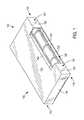
- FIG. 1is a perspective view of an electronic cigarette packaging in accordance with an exemplary embodiment.
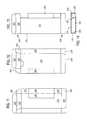
- FIG. 2is a blank for forming an electronic cigarette packaging in accordance with an exemplary embodiment.
- FIG. 3is a bottom view of a partially erected blank as shown in FIG. 2 in accordance with an exemplary embodiment.
- FIG. 4is a partial view of a second glue flap of a blank as shown in FIG. 2 in accordance with an exemplary embodiment.
- FIG. 5is a frontal view of an erected blank as shown in FIG. 2 in accordance with an exemplary embodiment.
- FIG. 6is a side view of an elongate, tubular body which contains an exemplary electronic cigarette.
- FIG. 7is a perspective view from the general direction of arrow VII in FIG. 6 of a cylindrical tubular body.
- FIG. 8is a perspective view from the general direction of arrow VII in FIG. 6 of a square elongate tubular body.
- FIG. 9is a perspective view from the general direction of arrow VII in FIG. 6 of a hexagonal elongate tubular body.
- FIG. 10is a perspective view from the general direction of arrow VII in FIG. 6 of an oval elongate body.
- FIG. 11is a planar front view of a glued, un-erected box structure in accordance with an exemplary embodiment.
- FIG. 12is a planar rear view of a glued, un-erected box structure in accordance with an exemplary embodiment.
- FIG. 13is a planar front view of a glued, erected, open-ended, box structure in accordance with an exemplary embodiment.
- FIG. 14is an end view of the box structure shown in FIG. 13 .
- FIG. 15is a representation of and in view of an alternate box structure having a greater depth then the exemplary embodiment shown in FIG. 1 .
- FIG. 16is a side view representation of the exist alternate embodiment of FIG. 15 .
- a blank 200for forming a display package 100 ( FIG. 1 ) operable to contain at least one electronic cigarette is disclosed.
- the at least one electronic cigarettecan be held securely within an elongated hollow cylinder or tube within a view recess or side edge cavity 120 along an outer side edge portion of the package 100 , such that the electronic cigarette is visible to a purchaser and/or consumer.
- FIG. 1is a perspective view of an electronic cigarette packaging 100 in accordance with an exemplary embodiment.
- the electronic cigarette packaging 100includes a rectangular box portion 110 , which is a substantially rectangular parallelepipedal shaped box, with right-angled longitudinal and right-angled transverse edges.
- the rectangular box portion 110includes a viewing window or cavity 120 , which is configured to receive an encased electronic cigarette.
- the electronic cigaretteis preferably encased in a transparent/translucent, tubular or elongated hollow cylinder (or body) 130 , which is configured to fit within the viewing recess or side edge cavity 120 of the box portion 110 of the electronic cigarette package 100 .
- the tubular or elongated hollow cylinder 130is a transparent hollow cylinder having at least one removable cap or lid on one end and a closed or preferably non-removable cap or end on the opposite end.
- the elongated hollow cylinder 130can be a clear glass or plastic tube.
- the elongate tubular body 130comprises a cylindrical, preferably transparent or translucent tube 410 and a removable cap 420 at the open end thereof.
- the contentscomprise an electronic cigarette or electronic cigar 430 (collectively referenced as “electronic smoking article”).
- the electronic cigarette 430may comprise a battery section 440 and a mouth piece or cartridge portion 450 and a coupling 460 between the two.
- the electronic cigarette 430includes a protective cover 470 over its buccal end portion.
- the upper and lower portions of the tubular body 130are not visible and are covered by a front panel portion of the box 110 , which portions are indicated by arrows a and b in FIG. 6 .
- An intermediate portion “c”remains visible to the consumer through the window or viewing recess 120 of the box 110 .
- tubular body 410 and the cap 420may be formed into other cross-sectional shapes such as shown in FIGS. 8-10 , which show an elongate tubular body 410 having a square cross-section, a hexagonal cross-section and an oval cross-section, respectively. Other rounded or multi-faceted cross-sections may be employed.
- the rectangular box portion 110includes a side panel 112 , a front panel 114 , a partial side panel 116 , a back panel 118 , a top panel 124 , and a bottom panel 134 .
- the viewing recess 120 within the rectangular box portion 110is formed by folding inwardly a front recess panel 140 located along an outer edge or portion of a front panel 114 and a side recess panel 142 located along the side panel 116 of the rectangular box portion 110 .
- the recess panels 140 , 142are preferably about 90 degrees (or perpendicular) to the front panel 114 and the cavity side panel 116 , respectively.
- the side panel 116comprises an upper side panel portion 116 and a lower side panel portion 116 ′, which are collectively referenced as side panel 116 .
- the window or viewing cavity 120extends a distance less than a height of the front panel 112 to establish retention portions 117 , 117 ′, which retain the end portions of elongated hollow cylinder 130 within box 110 , with portion of the cylinder 130 viewable along the cavity 120 .
- the length of the side edge cavityis less than the length of the hollow cylinder 130 .
- the length of the hollow cylinder 130can be substantially the same as the length of the front panel 114 so as to limit up-and-down movement of the cylinder (tube) 130
- the ends (not shown) of the hollow cylinder 130can be covered by the retention portions 117 , 117 ′ of the box 100 .
- the diameter of the hollow cylinder 130is approximately the same as a width of the cavity or side edge cavity 120 , and which corresponds to the width of the recess panels 140 , 142 .
- a blank 200 for forming a rectangular box 110 having a cavity 120 , which is operable to contain a hollow elongated cylinder 130is shown in FIG. 2 .
- the blank 200includes a first complete side panel 212 connected to a front panel 214 along a first fold line 241 .
- the first fold line 241extends along a first side edge 281 of the front panel 214 .
- Upper and lower side panel portions, 216 , 216 ′(collectively side panel 216 ) are connected to the front panel 214 along a second fold line 243 .
- the second fold line 243extends along a second side edge 283 of the front panel 214 .
- a back panel 218is connected to the cavity side panel 216 along a third fold line 245 .
- the third fold line 245extends along a first side edge 285 of the back panel 218 .
- a first glue panel 220connects to the back panel 218 along a fourth fold line 247 .
- the fourth fold line 247extends along a second side edge 287 of the back panel 218 .
- the blank 200also includes a first dust panel 222 connected to the side panel 212 along a top edge 291 of the side panel 212 .
- a top panel 224is connected to the front panel 214 along a fifth fold line 261 .
- the fifth fold line 261extends along a top edge 293 of the front panel 214 .
- the top panel 224has an upper flap panel (or tuck panel) 223 and an end (top) panel 225 .
- the upper flap panel or tuck panel 223is connected to the end panel 225 along a sixth fold line 271 .
- a second dust panel 226is connected to the cavity side panel 216 along a top edge 295 of the cavity side panel 216 .
- An outer bottom panel 234is connected to the front panel 214 along a seventh fold line 251 .
- the seventh fold line 251extends along a bottom edge 252 of the front panel 214 .
- a second (inner) glue panel 238is connected to the back panel 218 along an eighth fold line 253 .
- the eighth fold line 253extends along a bottom edge 254 of the back panel 218 .
- the blank 200also includes an upper cut line 282 and a lower cut line 284 extending transversely across an upper and a lower portion of the front panel 214 adjacent to the upper and lower side panel portions 216 , 216 ′ and extending across the cavity side panel 216 , respectively.
- the upper cut line 282 and the lower cut line 284form a first cavity panel 240 and a second cavity panel 242 within the front panel 214 and between the side panel portions 216 , 216 ′, respectively.
- a ninth (scored) fold line 244extends between an inner edge 246 of the upper cut line 282 and an inner edge 248 of the lower cut line 284 on the front panel 214 .
- the first cavity panel 240 and the second cavity panel 242are positioned perpendicular to the front panel 214 and the cavity side panel 216 , respectively. Panels 240 and 242 form the window or recess 120 .
- the cavity 120receives the elongated hollow cylinder 130 .
- the upper and lower cut lines 282 , 284extend across the front panel 214 a distance equal to a width of the cavity side panel 216 .
- the side panel 212has a vertical free edge 211 .
- the first side panel 212 and the cavity side panel 216each includes a lower free edge 292 , 296 .
- each of the first and second dust panels 222 , 226has an outer edge 272 , 276 with a slightly recessed portion 273 on the outer edge 272 , 276 opposite to the front panel 214 .
- Each recessed portion 273(positioned above the side outer edge 222 a ) includes an inwardly angled edge 273 a , which extends inward towards the top outer edge 272 and a slightly vertical upper edge 273 b extending to the outer edge 272 .
- the top panel 224 , the bottom panel 234 , and the second glue panel 238each have a free outer edge 274 , 294 , 298 .
- the back panel 218includes a recessed portion 202 within an upper edge 297 of the back panel 218 , which provides assistance and/or access for a consumer to contents enclosed within the box 110 such as a booklet 150 , which may be stored within the box portion 110 of the electronic cigarette packaging 100 .
- the blank 200may include a finish or varnish on the clay (printable) side of the blank 200 .
- the first glue panel 220 and the second glue panel 238can each include a varnish free area or portion 258 , 259 , which may improve the bonding formed by the glue, for example, a hot-melt adhesive material, and/or adhesive tape 400 ( FIG. 4 ).
- the first glue panel 220has a pair of angled edges 255 , 257 , which are slightly tapered to a vertical free edge 256 .
- the side panel 212has a width of about 13.0 mm and a height of about 109 mm.
- the front panel 214has a width of about 55 mm and a height of about 110 mm.
- the cavity side panel 216(portions 216 , 216 ′) has a width of about 14.0 mm and a height of about 109 mm.
- the back panel 218has a width of about 54.5 mm and a height of about 109 mm.
- the first glue panel 220has a width of about 11.0 mm and a height of about 109 mm.
- the first cavity panel 240 and the second cavity panel 242have a height of about 69 mm and a width of about 14.0 mm.
- a distance from the cut lines 282 , 284 to the upper edges 293 , 295 of the front panel 214 and the cavity side panel 216 , and the lower edges 252 , 296 of the front panel 214 and the cavity side panel 216is about 20 mm.
- the cavity 120has a height of about 69 mm and a width of about 14.0 mm and depth of about 14.0 mm.
- the first dust panel 222has a width of about 13.0 mm and a height of about 12.5 mm.
- the upper flap panel or tuck panel 223has a width of about 54 mm and a height of about 12.0 mm.
- the corners of the tuck panel 223are rounded 227 .
- the end panel 225has a width of about 55 mm and a height of about 12.5 mm.
- the end panel 225has a pair of slits 206 , 208 , parallel to the sixth fold line 271 , with downward turning end slit portions 206 a / 208 a contacting the sixth fold line 271 .
- the second dust panel 226has a width of about 14.0 mm and a height of about 12.4 mm.
- the bottom panel 234has a width of about 55 mm and a height of about 12.0 mm.
- the corners 237 of the bottom panel (or end panel) 234are slightly round at a radius of about 1.0 mm.
- first glue panel 220has a pair of angled outer edges 255 , 257 , which extend from the second side edge 287 of the back panel 218 inward at an angle of about 10 to 30 degrees and more preferably about 20 degrees.
- the second glue panel 238has a width of about 54.5 mm and a height of about 12.0 mm.
- the vertical edges 277 of the second glue panel 238can be angled, for example, angled at about 2.5 to 7.5 degrees and more preferably about 5.0 degrees.
- the corners 239 of the second glue panel 238can be rounded at a radius of about 1.0 mm.
- the back panel 218has a recess 202 on an upper edge 297 thereof.
- the recess 202can have a radius of about 9.3 mm and a depth of about 7 mm.
- the recess 202is preferably located in a center portion of the upper edge 297 of the back panel 218 so as to provide an equal distance from the first side edge 285 and the second side edge 287 to a corresponding edge 204 of the recess 202 .
- the assembled boxhas a height of about 111.0 mm, a width of about 55.0 mm and a depth of about 14.0 mm.
- the blank 200in a flat state, has a height of 146.5 mm and a width of about 147.5 mm.
- the partially assembled box 200is shipped for assembly in a folded and glued format.
- the blank 200is formed of a material selected from the group consisting of cardboard, paperboard, plastic, metal, or combinations thereof.
- the blank 200is formed of cardboard having a weight ranging from about 100 grams per square meter to about 350 grams per square meter.
- FIG. 2the clay coated side of the blank 200 is shown.
- the blank 200includes one or more of printing, embossing, debossing, embellishments and combinations thereof on an outer surface of the blank 200 .
- the blank 200may be formed from any suitable materials including, but not limited to, cardboard, paperboard, plastic, metal, or combinations thereof.
- the blank 200is formed from one or more folded laminar cardboard blanks.
- the cardboardhas a weight ranging from about 100 grams per square meter (gsm) to about 350 grams per square meter.
- exterior surfaces of the box 110may be printed, embossed, debossed or otherwise embellished with manufacturer or brand logos, trademarks, slogans and other consumer information and indicia.
- a resultant box structure 300 from a method for assembling the box 110 from a single laminar blank 200is provided.
- the laminar blank 200is preferably partially folded and glued prior to shipping to a facility for assembly.
- the second and fourth fold lines 243 , 247are folded 180 degrees.
- the first and third fold lines 241 , 245are then folded 180 degrees, and the second cavity panel 242 , which comprises the area of the cavity side panel 216 between the upper cut line 282 and the lower cut line 284 is glued to an adjacent inside portion (not shown) of the back panel 218 .
- the first glue panel 220is then glued to a back side of the side panel 212 .
- the resultant box 300 structuremay be flattened to facilitate shipping. It is preferable that the resultant box 300 is supplied by the manufacturer folded and glued as set forth above. In addition, it is preferable that the resultant boxes 300 are not packed tightly so as to flatten them completely.
- a glued, yet un-erected box structureis shown in the frontal view of FIG. 11 wherein the window, recess panel 242 is glued to an interior surface of the back panel 218 , the latter not being visible in FIG. 11 .
- a representation of window panel 242is shown in dashed lines.
- FIGS. 13 and 14upon erection, an open-ended structure of box 110 is established wherein a windowed compartment 510 is established adjacent the side panel 216 .
- the windowed compartment 510comprises the lower retention portion 117 (defined between adjacent, lower portions of the side, front and back panels 116 , 114 , 118 ) of the box 110 , the window 120 (defined by the window panels 140 , 142 ) and the upper retention portion 117 ′ (defined between adjacent, upper portions of the side, front and back panels 116 ′, 114 , 118 of the box 110 ).
- the open-ended structure of the box 110further comprises in the exemplary embodiment, a second optional compartment 520 which is provided within the remainder of the confines of the box 110 for housing pamphlets or supplementary devices such as wall chargers, electrical connectors or the like. Insertion of a tubular body 130 into the windowed compartment 520 and closure of end portions 530 and 540 of the box 110 completes the packaging 100 of the exemplary embodiment shown in FIG. 1 .
- the proportions of the box 110may be changed to provide a greater depth such as shown in FIG. 15 and/or a greater height.
- the window panel 242would not necessarily be glued to adjacent portions of the back panel 218 .
- the window recess 120would be established by either manually or mechanically pushing (folding) panels 240 and 242 inwardly into the box structure 110 ′ upon erection of the box structure 110 ′.
- the lower and upper retention portions 117 , 117 ′comprise on adjacent portions of the front panel 114 and the side panels portions 116 , 116 ′.
- the retention portions 117 , 117 ′may serve to block from view selected portions of the tubular body 130 , such as for example, the stopper 410 . Furthermore, the retention portions 117 , 117 ′ preferably each have a sufficient length to provide adequate resistance against someone pulling the product laterally apart from the box structure 110 .
- box 110may be provided tuck flaps at both ends, instead of at only the top end as shown FIG. 2 .
- FIG. 4is a partial view of a glue flap 238 of the blank 200 as shown in FIG. 2 in accordance with an exemplary embodiment.
- a pressure sensitive tape 400can be used to attach or fix the first glue flap 220 to the side panel 212 and/or the second glue flap 238 to the bottom panel 234 .
- a pressure sensitive tape 400 having a width of about 40.5 mm and a height of less than about 11.0 mmcan be placed on the second glue flap 238 at a distance of about 1.0 mm from a lower edge 298 of the second glue flap 238 .
- the pressure sensitive tape 400is about 7.0 mm from the angled edges of the second glue flap 238 .
- the pressure sensitive tape 400is a 3M® Extended Liner Tape 476XL having a 1 ⁇ 2 inch wide liner and 1 ⁇ 4 inch adhesive.
- FIG. 5is a frontal view of an electronic cigarette package 100 as shown in FIG. 1 .
- the package 100includes an instruction booklet 150 contained within an inner portion 152 of the package 100 .
- frontAs used herein, the terms “front”, “back”, “upper”, “lower”, “side”, “top”, “bottom”, “left”, “right” and other terms used to describe relative positions of the components of the box refer to the box 110 in an upright position.
- the fold and/or score linesare 2 pt. rule.
- the term “longitudinal”refers to a direction from bottom to top or vice versa of the box 110 .
- transverserefers to a direction perpendicular to the longitudinal direction.
- a fold linecan be any substantially linear, although not necessarily straight, form of weakening that facilitates folding therealong. More specifically, but not for the purpose of narrowing the scope of the present disclosure, fold lines include: a score line, such as lines formed with a blunt scoring knife, or the like, which creates a crushed portion in the material along the desired line of weakness. In addition, cut line extends partially into and/or completely through the material along the desired line of weakness so as to separate one portion of a panel or panels from another portion of a panel or panels.
Landscapes
- Engineering & Computer Science (AREA)
- Mechanical Engineering (AREA)
- Cartons (AREA)
- Packaging Of Annular Or Rod-Shaped Articles, Wearing Apparel, Cassettes, Or The Like (AREA)
Abstract
Description
Claims (30)
Priority Applications (13)
| Application Number | Priority Date | Filing Date | Title |
|---|---|---|---|
| US13/843,314US10470492B2 (en) | 2013-03-15 | 2013-03-15 | Display package |
| CN201480024177.3ACN105358442A (en) | 2013-03-15 | 2014-03-10 | Display package |
| PL14713355TPL2969788T3 (en) | 2013-03-15 | 2014-03-10 | Display package |
| PCT/US2014/022719WO2014150251A1 (en) | 2013-03-15 | 2014-03-10 | Display package |
| MYPI2015002388AMY178088A (en) | 2013-03-15 | 2014-03-10 | Display package |
| CA2906479ACA2906479A1 (en) | 2013-03-15 | 2014-03-10 | Display package |
| KR1020157029581AKR20160012107A (en) | 2013-03-15 | 2014-03-10 | Display package |
| EP14713355.7AEP2969788B1 (en) | 2013-03-15 | 2014-03-10 | Display package |
| MA38516AMA38516B1 (en) | 2013-03-15 | 2014-03-10 | Packaging display |
| ES14713355.7TES2633996T3 (en) | 2013-03-15 | 2014-03-10 | Exhibition Package |
| RU2015144319ARU2651440C2 (en) | 2013-03-15 | 2014-03-10 | Display package |
| ARP140101243AAR095618A1 (en) | 2013-03-15 | 2014-03-17 | PRESENTATION PACK |
| UAA201510056AUA116649C2 (en) | 2013-03-15 | 2014-10-03 | Display package |
Applications Claiming Priority (1)
| Application Number | Priority Date | Filing Date | Title |
|---|---|---|---|
| US13/843,314US10470492B2 (en) | 2013-03-15 | 2013-03-15 | Display package |
Publications (2)
| Publication Number | Publication Date |
|---|---|
| US20140262871A1 US20140262871A1 (en) | 2014-09-18 |
| US10470492B2true US10470492B2 (en) | 2019-11-12 |
Family
ID=50389557
Family Applications (1)
| Application Number | Title | Priority Date | Filing Date |
|---|---|---|---|
| US13/843,314ActiveUS10470492B2 (en) | 2013-03-15 | 2013-03-15 | Display package |
Country Status (13)
| Country | Link |
|---|---|
| US (1) | US10470492B2 (en) |
| EP (1) | EP2969788B1 (en) |
| KR (1) | KR20160012107A (en) |
| CN (1) | CN105358442A (en) |
| AR (1) | AR095618A1 (en) |
| CA (1) | CA2906479A1 (en) |
| ES (1) | ES2633996T3 (en) |
| MA (1) | MA38516B1 (en) |
| MY (1) | MY178088A (en) |
| PL (1) | PL2969788T3 (en) |
| RU (1) | RU2651440C2 (en) |
| UA (1) | UA116649C2 (en) |
| WO (1) | WO2014150251A1 (en) |
Families Citing this family (20)
| Publication number | Priority date | Publication date | Assignee | Title |
|---|---|---|---|---|
| US9854839B2 (en) | 2012-01-31 | 2018-01-02 | Altria Client Services Llc | Electronic vaping device and method |
| GB201205243D0 (en) | 2012-03-26 | 2012-05-09 | Kraft Foods R & D Inc | Packaging and method of opening |
| GB2511560B (en) | 2013-03-07 | 2018-11-14 | Mondelez Uk R&D Ltd | Improved Packaging and Method of Forming Packaging |
| GB2511559B (en) | 2013-03-07 | 2018-11-14 | Mondelez Uk R&D Ltd | Improved Packaging and Method of Forming Packaging |
| USD710713S1 (en) | 2013-03-15 | 2014-08-12 | Altria Client Services Inc. | Display package |
| US10470492B2 (en) | 2013-03-15 | 2019-11-12 | Altria Client Services Llc | Display package |
| USD743248S1 (en) | 2013-03-15 | 2015-11-17 | Altria Client Services Llc | Display package |
| US9974334B2 (en)* | 2014-01-17 | 2018-05-22 | Rai Strategic Holdings, Inc. | Electronic smoking article with improved storage of aerosol precursor compositions |
| EA201692441A1 (en) | 2014-05-29 | 2017-05-31 | Олтриа Клайент Сервисиз Ллк | METHOD OF DISTRIBUTION |
| WO2016054391A1 (en)* | 2014-10-02 | 2016-04-07 | Altria Client Services Llc. | Display package |
| USD811874S1 (en) | 2016-11-10 | 2018-03-06 | Altria Client Services Llc | Cartridge display package |
| USD855880S1 (en)* | 2018-01-15 | 2019-08-06 | Okan Sarsurluoglu | Vape box |
| EP3743977A1 (en) | 2018-01-26 | 2020-12-02 | Juul Labs, Inc. | Charging case assembly |
| USD853022S1 (en)* | 2018-02-06 | 2019-07-02 | Ikey Srour | E-cigarette holder |
| USD860523S1 (en)* | 2018-02-28 | 2019-09-17 | Juul Labs, Inc. | Case |
| JP1638846S (en) | 2018-02-28 | 2019-08-13 | ||
| USD868577S1 (en) | 2018-08-20 | 2019-12-03 | Rai Strategic Holdings, Inc. | Vapor product packaging |
| USD864710S1 (en) | 2018-08-20 | 2019-10-29 | Rai Strategic Holdings, Inc. | Vapor product packaging |
| USD894730S1 (en) | 2018-08-30 | 2020-09-01 | Rai Strategic Holdings, Inc. | Packaging |
| US11553734B2 (en) | 2018-11-08 | 2023-01-17 | Juul Labs, Inc. | Cartridges for vaporizer devices |
Citations (103)
| Publication number | Priority date | Publication date | Assignee | Title |
|---|---|---|---|---|
| US2162089A (en)* | 1937-12-03 | 1939-06-13 | Keystone Paper Box Company Inc | Article container |
| US2354239A (en)* | 1941-09-06 | 1944-07-25 | Nat Folding Box Co | Telescopic container |
| US2464951A (en)* | 1945-12-14 | 1949-03-22 | Edward Mcsweeney | Display box |
| US2611529A (en) | 1948-10-27 | 1952-09-23 | John F Currivan | Integral carton for protection of fragile articles |
| US2727620A (en)* | 1952-12-29 | 1955-12-20 | Sutherland Paper Co | Collapsible display carton |
| US2854182A (en) | 1955-12-19 | 1958-09-30 | Cornell Paperboard Products Co | Windowed carton with integral dividers |
| US2913101A (en) | 1957-08-01 | 1959-11-17 | Waldorf Paper Products Co | Display cartons |
| US2937743A (en) | 1958-01-31 | 1960-05-24 | Kvp Sutherland Paper Co | Display carton |
| US2948390A (en) | 1959-06-23 | 1960-08-09 | Fibreboard Paper Products Corp | Window carton |
| US2980242A (en)* | 1959-03-31 | 1961-04-18 | Procter & Gamble | Open faced cartons for collapsible tubes |
| US3029934A (en) | 1960-04-12 | 1962-04-17 | Waldorf Paper Products Co | Combined carton and article holder |
| US3033357A (en) | 1958-04-10 | 1962-05-08 | Vogel Lida Brown | Apparel kit |
| US3054505A (en) | 1960-04-12 | 1962-09-18 | Waldorf Paper Products Co | Multi-article carton |
| US3186622A (en)* | 1963-08-06 | 1965-06-01 | Monsanto Co | Plural compartment window container and blank therefor |
| US3206098A (en) | 1964-05-26 | 1965-09-14 | Bradford Speed Packaging And D | End wall construction of folding boxes |
| US3233726A (en)* | 1963-07-24 | 1966-02-08 | Nat Biscuit Co | Compartmented window cartons |
| US3298504A (en) | 1964-12-21 | 1967-01-17 | Pioneer Packaging Inc | Display carton |
| US3326444A (en) | 1964-09-02 | 1967-06-20 | Reynolds Metals Co | Multi-compartment carton |
| US3521810A (en) | 1968-06-21 | 1970-07-28 | Hoerner Waldorf Corp | Variable size container |
| US3659704A (en) | 1969-10-02 | 1972-05-02 | Container Corp | Display carton having structure for product support therein |
| US3680687A (en)* | 1970-06-01 | 1972-08-01 | Federal Paper Board Co Inc | Display carton |
| US3767037A (en) | 1971-03-25 | 1973-10-23 | Packaging Corp America | Package construction |
| US3828923A (en) | 1972-12-07 | 1974-08-13 | Reynolds Tobacco Co R | Composite slideable dispensing carton |
| US4106615A (en) | 1975-02-06 | 1978-08-15 | Lion Hamigaki Kabushiki Kaisha | Box blank and assembled package box for display |
| US4109786A (en) | 1977-01-10 | 1978-08-29 | Champion International Corporation | Carton for round articles |
| US4125185A (en)* | 1977-04-21 | 1978-11-14 | Champion International Corporation | Divided display carton and blank therefor |
| US4342417A (en) | 1980-08-18 | 1982-08-03 | Westvaco Corporation | End loaded compartmented carton |
| US4353694A (en) | 1980-01-25 | 1982-10-12 | Pelerin Joseph J | Dental kit for performing root canals |
| GB2106366A (en) | 1981-09-29 | 1983-04-13 | Meggle Milchind Gmbh & Co | >Imitation cheese base masses |
| US4397393A (en) | 1981-06-09 | 1983-08-09 | The Coca-Cola Company | Fast food carryout package |
| US4487311A (en) | 1983-04-14 | 1984-12-11 | International Paper Company | Dual compartment display carton |
| US4524871A (en) | 1982-07-22 | 1985-06-25 | Klinger Max H | Receptacle for containing disposable cloths and a stick-like container |
| USD290175S (en) | 1984-09-28 | 1987-06-02 | Cosmede Anstalt | Cosmetic compact |
| US4848563A (en) | 1987-12-17 | 1989-07-18 | Robbins Sports | Display package and method of manufacture |
| US4865204A (en) | 1983-01-24 | 1989-09-12 | The Procter & Gamble Company | Carton structure having easily openable compression resistant end |
| US4957202A (en) | 1989-08-21 | 1990-09-18 | Sunstar Kabushiki Kaisha | Commodity package with auxiliary container portion |
| USD314146S (en) | 1988-02-16 | 1991-01-29 | Light & Shadow, Inc. | Container for film spool |
| USD318802S (en) | 1988-02-18 | 1991-08-06 | Egide Mark A | Display carton |
| US5044548A (en)* | 1989-09-28 | 1991-09-03 | Leo T. Olsen | Stacking ball carton, blank and method |
| EP0465257A1 (en) | 1990-07-06 | 1992-01-08 | Colgate-Palmolive Company | Display package, display carton and blank therefor |
| US5226534A (en) | 1992-04-14 | 1993-07-13 | Tritec International Corporation | Package for safety razors |
| USD353712S (en) | 1993-02-22 | 1994-12-27 | Aalders Hubertine M E | Combination spectacle case and contact lens vial |
| DE4339645A1 (en) | 1993-11-20 | 1995-05-24 | Marinall Vertrieb & Media Serv | Folding box for holding containers |
| USD371959S (en) | 1995-02-17 | 1996-07-23 | Indiana Carton, Inc. | Truck box |
| US5848690A (en)* | 1996-10-24 | 1998-12-15 | Wilson Sporting Goods Co. | Tennis ball container with pressure seal and screw-on cap |
| US5944183A (en)* | 1998-03-30 | 1999-08-31 | Jefferson Smurfit Corporation | Carton with glued liner incorporating an integral cell |
| US6050416A (en) | 1996-04-01 | 2000-04-18 | The Mead Corporation | Display package |
| US6244501B1 (en)* | 1999-04-29 | 2001-06-12 | Deokwhan Choi | Multi-purpose package assembly |
| US6460703B1 (en)* | 2001-05-21 | 2002-10-08 | S.C. Johnson & Son, Inc. | Display box and method for packaging an article in the box |
| USD466406S1 (en)* | 2001-09-28 | 2002-12-03 | Harman International Industries, Inc. | Box |
| US6491211B1 (en) | 2001-08-03 | 2002-12-10 | Scott & Daniells, Inc. | Child resistant carton and method for using the same |
| USD466804S1 (en) | 2001-09-28 | 2002-12-10 | Harman International Industries, Inc. | Box |
| CN1436145A (en) | 2000-06-06 | 2003-08-13 | Vkr控股有限公司 | Package for rod-shaped articles along with accessories comprising inspection window |
| US20040182917A1 (en)* | 2003-01-16 | 2004-09-23 | International Paper Company | Box with lenticular lens insert |
| US20050045526A1 (en) | 2003-08-01 | 2005-03-03 | Arnaud Constant | Packaging for cosmetic, human therapeutic or human hygiene product receptacle with improved gussets configuration |
| US20050236282A1 (en) | 2002-08-27 | 2005-10-27 | Huska Brenda C | Compartmentalized cigarette snuffer and receptacle |
| US20060208051A1 (en)* | 2005-03-16 | 2006-09-21 | Chuang Chao-Ken | Commodity box |
| CN1910084A (en) | 2004-12-01 | 2007-02-07 | 花王株式会社 | Plastic box |
| USD546669S1 (en) | 2005-12-20 | 2007-07-17 | The Procter & Gamble Company | Package for a hair treatment product |
| US20070228130A1 (en)* | 2004-05-13 | 2007-10-04 | Rohto Pharmaceutical Co., Ltd. | Packaging Box |
| USD563218S1 (en) | 2006-07-17 | 2008-03-04 | The Procter & Gamble Company | Container |
| CN201043070Y (en) | 2007-06-05 | 2008-04-02 | 苏州普丽雅包装有限公司 | Integral packing box for notebook-type computer |
| US7424955B2 (en) | 2004-07-30 | 2008-09-16 | Asustek Computer Inc. | Packing structure and buffer device thereof |
| CN101353092A (en) | 2007-07-26 | 2009-01-28 | 广达电脑股份有限公司 | Folding type packing box |
| USD588449S1 (en) | 2008-03-10 | 2009-03-17 | Wilton Industries, Inc. | Picture frame package |
| USD600110S1 (en) | 2009-03-05 | 2009-09-15 | The Procter & Gamble Company | Carton |
| USD601009S1 (en) | 2009-02-27 | 2009-09-29 | Kevin Shinn | Cosmetic packaging |
| USD602637S1 (en) | 2008-08-20 | 2009-10-20 | Jacek Helenowski | Cosmetic holder |
| US7650997B2 (en) | 2004-06-28 | 2010-01-26 | Shimano Inc. | Merchandise housing container |
| USD610000S1 (en) | 2009-09-09 | 2010-02-16 | Randa Accessories Leather Goods, LLC | Box for a pair of belts |
| CN102232040A (en) | 2008-12-01 | 2011-11-02 | 高露洁-棕榄公司 | A display carton for a plurality of products |
| US20110297559A1 (en) | 2010-06-04 | 2011-12-08 | Robert Davis | Contact lens packaging methods and systems |
| USD654786S1 (en) | 2010-04-12 | 2012-02-28 | On Food Inc. | Container for food items |
| US20120061290A1 (en)* | 2010-09-10 | 2012-03-15 | Guillaume Delaunay | Carton with opening for displaying product |
| US8191707B2 (en)* | 2010-10-29 | 2012-06-05 | Newell Window Furnishings, Inc. | Curtain rod package |
| US8235204B2 (en) | 2009-12-03 | 2012-08-07 | Howell Packaging, Division of F.M. Howell & Company | Lockable package with slide tray |
| US20120227753A1 (en) | 2010-12-06 | 2012-09-13 | Newton Kyle D | Charger Package for Electronic Cigarette Components |
| USD671401S1 (en) | 2010-11-10 | 2012-11-27 | Braun Gmbh | Packaging for shaver |
| US20130001126A1 (en)* | 2011-06-30 | 2013-01-03 | Gu Yunpeng | Packaging and Display Case For Dissimilar Objects |
| USD679950S1 (en) | 2011-06-03 | 2013-04-16 | This, Llc | Food container housing food articles |
| US20130140200A1 (en)* | 2011-10-17 | 2013-06-06 | Mark Scatterday | Electronic cigarette container and method therefor |
| CN203186741U (en) | 2013-04-25 | 2013-09-11 | 武汉虹之彩包装印刷有限公司 | Multifunctional double-layer cigarette packet bar case |
| US20130233743A1 (en)* | 2012-03-06 | 2013-09-12 | Robert Hillard | Package System for Particulate Organic Product |
| US20130342157A1 (en) | 2012-06-20 | 2013-12-26 | Qiuming Liu | Electronic Cigarette Case |
| USD699103S1 (en) | 2012-09-04 | 2014-02-11 | Wm. Wrigley Jr. Company | Package with window |
| USD699562S1 (en) | 2009-04-21 | 2014-02-18 | The Procter & Gamble Company | Shaver package |
| USD700049S1 (en) | 2013-07-25 | 2014-02-25 | Sherri Lee Athay | Package for a chocolate confection |
| CN103619715A (en) | 2011-06-14 | 2014-03-05 | 菲利普莫里斯生产公司 | Container and lifting means for an article |
| US20140097103A1 (en) | 2012-07-31 | 2014-04-10 | The Safe Cig, Llc | Container device and apparatus |
| USD702546S1 (en) | 2012-09-28 | 2014-04-15 | Leo Paper Bags Manufacturing (1982) Limited | Folding rigid box |
| USD710713S1 (en) | 2013-03-15 | 2014-08-12 | Altria Client Services Inc. | Display package |
| US20140262871A1 (en) | 2013-03-15 | 2014-09-18 | Altria Client Services Inc. | Display package |
| USD734145S1 (en) | 2014-08-11 | 2015-07-14 | Altria Client Services Inc. | Display package |
| USD735572S1 (en) | 2014-08-11 | 2015-08-04 | Altria Client Services Inc. | Display package |
| USD738716S1 (en) | 2013-10-14 | 2015-09-15 | Nicoventures Holdings Limited | Package |
| USD743248S1 (en) | 2013-03-15 | 2015-11-17 | Altria Client Services Llc | Display package |
| US20150342252A1 (en) | 2014-05-29 | 2015-12-03 | Scott A. Fath | Method of displaying electronic vaping device, display packages with divider, blanks for forming display package for containing electronic vaping device, and method of manufacturing display package for electronic vaping device |
| USD746700S1 (en) | 2014-01-29 | 2016-01-05 | Liberty Hardware Mfg. Corp. | Handle packaging |
| US20160096658A1 (en) | 2014-10-02 | 2016-04-07 | Scott A. Fath | Display package |
| USD756781S1 (en) | 2014-09-17 | 2016-05-24 | Quad/Graphics, Inc. | Display panel for a sampler |
| USD756780S1 (en) | 2014-09-17 | 2016-05-24 | Quad/Graphics, Inc. | Display panel for a sampler |
| US9527643B2 (en) | 2015-01-21 | 2016-12-27 | Target Brands, Inc. | Package with open chamber |
| USD787933S1 (en) | 2015-05-15 | 2017-05-30 | Inno-Pak Llc | Closeable container |
- 2013
- 2013-03-15USUS13/843,314patent/US10470492B2/enactiveActive
- 2014
- 2014-03-10EPEP14713355.7Apatent/EP2969788B1/ennot_activeNot-in-force
- 2014-03-10MAMA38516Apatent/MA38516B1/enunknown
- 2014-03-10KRKR1020157029581Apatent/KR20160012107A/ennot_activeWithdrawn
- 2014-03-10MYMYPI2015002388Apatent/MY178088A/enunknown
- 2014-03-10WOPCT/US2014/022719patent/WO2014150251A1/enactiveApplication Filing
- 2014-03-10ESES14713355.7Tpatent/ES2633996T3/enactiveActive
- 2014-03-10RURU2015144319Apatent/RU2651440C2/ennot_activeIP Right Cessation
- 2014-03-10CACA2906479Apatent/CA2906479A1/ennot_activeAbandoned
- 2014-03-10PLPL14713355Tpatent/PL2969788T3/enunknown
- 2014-03-10CNCN201480024177.3Apatent/CN105358442A/enactivePending
- 2014-03-17ARARP140101243Apatent/AR095618A1/enunknown
- 2014-10-03UAUAA201510056Apatent/UA116649C2/enunknown
Patent Citations (112)
| Publication number | Priority date | Publication date | Assignee | Title |
|---|---|---|---|---|
| US2162089A (en)* | 1937-12-03 | 1939-06-13 | Keystone Paper Box Company Inc | Article container |
| US2354239A (en)* | 1941-09-06 | 1944-07-25 | Nat Folding Box Co | Telescopic container |
| US2464951A (en)* | 1945-12-14 | 1949-03-22 | Edward Mcsweeney | Display box |
| US2611529A (en) | 1948-10-27 | 1952-09-23 | John F Currivan | Integral carton for protection of fragile articles |
| US2727620A (en)* | 1952-12-29 | 1955-12-20 | Sutherland Paper Co | Collapsible display carton |
| US2854182A (en) | 1955-12-19 | 1958-09-30 | Cornell Paperboard Products Co | Windowed carton with integral dividers |
| US2913101A (en) | 1957-08-01 | 1959-11-17 | Waldorf Paper Products Co | Display cartons |
| US2937743A (en) | 1958-01-31 | 1960-05-24 | Kvp Sutherland Paper Co | Display carton |
| US3033357A (en) | 1958-04-10 | 1962-05-08 | Vogel Lida Brown | Apparel kit |
| US2980242A (en)* | 1959-03-31 | 1961-04-18 | Procter & Gamble | Open faced cartons for collapsible tubes |
| US2948390A (en) | 1959-06-23 | 1960-08-09 | Fibreboard Paper Products Corp | Window carton |
| US3029934A (en) | 1960-04-12 | 1962-04-17 | Waldorf Paper Products Co | Combined carton and article holder |
| US3054505A (en) | 1960-04-12 | 1962-09-18 | Waldorf Paper Products Co | Multi-article carton |
| US3233726A (en)* | 1963-07-24 | 1966-02-08 | Nat Biscuit Co | Compartmented window cartons |
| US3186622A (en)* | 1963-08-06 | 1965-06-01 | Monsanto Co | Plural compartment window container and blank therefor |
| US3206098A (en) | 1964-05-26 | 1965-09-14 | Bradford Speed Packaging And D | End wall construction of folding boxes |
| US3326444A (en) | 1964-09-02 | 1967-06-20 | Reynolds Metals Co | Multi-compartment carton |
| US3298504A (en) | 1964-12-21 | 1967-01-17 | Pioneer Packaging Inc | Display carton |
| US3521810A (en) | 1968-06-21 | 1970-07-28 | Hoerner Waldorf Corp | Variable size container |
| US3659704A (en) | 1969-10-02 | 1972-05-02 | Container Corp | Display carton having structure for product support therein |
| US3680687A (en)* | 1970-06-01 | 1972-08-01 | Federal Paper Board Co Inc | Display carton |
| US3767037A (en) | 1971-03-25 | 1973-10-23 | Packaging Corp America | Package construction |
| US3828923A (en) | 1972-12-07 | 1974-08-13 | Reynolds Tobacco Co R | Composite slideable dispensing carton |
| US4106615A (en) | 1975-02-06 | 1978-08-15 | Lion Hamigaki Kabushiki Kaisha | Box blank and assembled package box for display |
| US4109786A (en) | 1977-01-10 | 1978-08-29 | Champion International Corporation | Carton for round articles |
| US4125185A (en)* | 1977-04-21 | 1978-11-14 | Champion International Corporation | Divided display carton and blank therefor |
| US4353694A (en) | 1980-01-25 | 1982-10-12 | Pelerin Joseph J | Dental kit for performing root canals |
| US4342417A (en) | 1980-08-18 | 1982-08-03 | Westvaco Corporation | End loaded compartmented carton |
| US4397393A (en) | 1981-06-09 | 1983-08-09 | The Coca-Cola Company | Fast food carryout package |
| GB2106366A (en) | 1981-09-29 | 1983-04-13 | Meggle Milchind Gmbh & Co | >Imitation cheese base masses |
| US4524871A (en) | 1982-07-22 | 1985-06-25 | Klinger Max H | Receptacle for containing disposable cloths and a stick-like container |
| US4865204A (en) | 1983-01-24 | 1989-09-12 | The Procter & Gamble Company | Carton structure having easily openable compression resistant end |
| US4487311A (en) | 1983-04-14 | 1984-12-11 | International Paper Company | Dual compartment display carton |
| USD290175S (en) | 1984-09-28 | 1987-06-02 | Cosmede Anstalt | Cosmetic compact |
| US4848563A (en) | 1987-12-17 | 1989-07-18 | Robbins Sports | Display package and method of manufacture |
| USD314146S (en) | 1988-02-16 | 1991-01-29 | Light & Shadow, Inc. | Container for film spool |
| USD318802S (en) | 1988-02-18 | 1991-08-06 | Egide Mark A | Display carton |
| US4957202A (en) | 1989-08-21 | 1990-09-18 | Sunstar Kabushiki Kaisha | Commodity package with auxiliary container portion |
| US5044548A (en)* | 1989-09-28 | 1991-09-03 | Leo T. Olsen | Stacking ball carton, blank and method |
| EP0465257A1 (en) | 1990-07-06 | 1992-01-08 | Colgate-Palmolive Company | Display package, display carton and blank therefor |
| US5226534A (en) | 1992-04-14 | 1993-07-13 | Tritec International Corporation | Package for safety razors |
| USD353712S (en) | 1993-02-22 | 1994-12-27 | Aalders Hubertine M E | Combination spectacle case and contact lens vial |
| DE4339645A1 (en) | 1993-11-20 | 1995-05-24 | Marinall Vertrieb & Media Serv | Folding box for holding containers |
| USD371959S (en) | 1995-02-17 | 1996-07-23 | Indiana Carton, Inc. | Truck box |
| US6050416A (en) | 1996-04-01 | 2000-04-18 | The Mead Corporation | Display package |
| US5848690A (en)* | 1996-10-24 | 1998-12-15 | Wilson Sporting Goods Co. | Tennis ball container with pressure seal and screw-on cap |
| US5944183A (en)* | 1998-03-30 | 1999-08-31 | Jefferson Smurfit Corporation | Carton with glued liner incorporating an integral cell |
| US6244501B1 (en)* | 1999-04-29 | 2001-06-12 | Deokwhan Choi | Multi-purpose package assembly |
| CN1436145A (en) | 2000-06-06 | 2003-08-13 | Vkr控股有限公司 | Package for rod-shaped articles along with accessories comprising inspection window |
| US6460703B1 (en)* | 2001-05-21 | 2002-10-08 | S.C. Johnson & Son, Inc. | Display box and method for packaging an article in the box |
| US6491211B1 (en) | 2001-08-03 | 2002-12-10 | Scott & Daniells, Inc. | Child resistant carton and method for using the same |
| USD466804S1 (en) | 2001-09-28 | 2002-12-10 | Harman International Industries, Inc. | Box |
| USD466406S1 (en)* | 2001-09-28 | 2002-12-03 | Harman International Industries, Inc. | Box |
| US20050236282A1 (en) | 2002-08-27 | 2005-10-27 | Huska Brenda C | Compartmentalized cigarette snuffer and receptacle |
| US20040182917A1 (en)* | 2003-01-16 | 2004-09-23 | International Paper Company | Box with lenticular lens insert |
| US20050045526A1 (en) | 2003-08-01 | 2005-03-03 | Arnaud Constant | Packaging for cosmetic, human therapeutic or human hygiene product receptacle with improved gussets configuration |
| US20070228130A1 (en)* | 2004-05-13 | 2007-10-04 | Rohto Pharmaceutical Co., Ltd. | Packaging Box |
| US7650997B2 (en) | 2004-06-28 | 2010-01-26 | Shimano Inc. | Merchandise housing container |
| US7424955B2 (en) | 2004-07-30 | 2008-09-16 | Asustek Computer Inc. | Packing structure and buffer device thereof |
| CN1910084A (en) | 2004-12-01 | 2007-02-07 | 花王株式会社 | Plastic box |
| EP1818266A1 (en) | 2004-12-01 | 2007-08-15 | Kao Corporation | Plastic box |
| US20060208051A1 (en)* | 2005-03-16 | 2006-09-21 | Chuang Chao-Ken | Commodity box |
| USD546669S1 (en) | 2005-12-20 | 2007-07-17 | The Procter & Gamble Company | Package for a hair treatment product |
| USD576871S1 (en) | 2005-12-20 | 2008-09-16 | The Procter & Gamble Company | Package for a hair treatment product |
| USD577286S1 (en) | 2005-12-20 | 2008-09-23 | The Procter & Gamble Company | Package for a hair treatment product |
| USD563218S1 (en) | 2006-07-17 | 2008-03-04 | The Procter & Gamble Company | Container |
| CN201043070Y (en) | 2007-06-05 | 2008-04-02 | 苏州普丽雅包装有限公司 | Integral packing box for notebook-type computer |
| CN101353092A (en) | 2007-07-26 | 2009-01-28 | 广达电脑股份有限公司 | Folding type packing box |
| USD588449S1 (en) | 2008-03-10 | 2009-03-17 | Wilton Industries, Inc. | Picture frame package |
| USD602637S1 (en) | 2008-08-20 | 2009-10-20 | Jacek Helenowski | Cosmetic holder |
| CN102232040A (en) | 2008-12-01 | 2011-11-02 | 高露洁-棕榄公司 | A display carton for a plurality of products |
| USD601009S1 (en) | 2009-02-27 | 2009-09-29 | Kevin Shinn | Cosmetic packaging |
| USD600110S1 (en) | 2009-03-05 | 2009-09-15 | The Procter & Gamble Company | Carton |
| USD699562S1 (en) | 2009-04-21 | 2014-02-18 | The Procter & Gamble Company | Shaver package |
| USD610000S1 (en) | 2009-09-09 | 2010-02-16 | Randa Accessories Leather Goods, LLC | Box for a pair of belts |
| US8235204B2 (en) | 2009-12-03 | 2012-08-07 | Howell Packaging, Division of F.M. Howell & Company | Lockable package with slide tray |
| USD654786S1 (en) | 2010-04-12 | 2012-02-28 | On Food Inc. | Container for food items |
| US20110297559A1 (en) | 2010-06-04 | 2011-12-08 | Robert Davis | Contact lens packaging methods and systems |
| US20120061290A1 (en)* | 2010-09-10 | 2012-03-15 | Guillaume Delaunay | Carton with opening for displaying product |
| US8191707B2 (en)* | 2010-10-29 | 2012-06-05 | Newell Window Furnishings, Inc. | Curtain rod package |
| USD671401S1 (en) | 2010-11-10 | 2012-11-27 | Braun Gmbh | Packaging for shaver |
| US20120227753A1 (en) | 2010-12-06 | 2012-09-13 | Newton Kyle D | Charger Package for Electronic Cigarette Components |
| USD679950S1 (en) | 2011-06-03 | 2013-04-16 | This, Llc | Food container housing food articles |
| CN103619715A (en) | 2011-06-14 | 2014-03-05 | 菲利普莫里斯生产公司 | Container and lifting means for an article |
| US20130001126A1 (en)* | 2011-06-30 | 2013-01-03 | Gu Yunpeng | Packaging and Display Case For Dissimilar Objects |
| US20130140200A1 (en)* | 2011-10-17 | 2013-06-06 | Mark Scatterday | Electronic cigarette container and method therefor |
| US8584843B2 (en) | 2012-03-06 | 2013-11-19 | Robert Hillard | Package system for particulate organic product |
| US20130233743A1 (en)* | 2012-03-06 | 2013-09-12 | Robert Hillard | Package System for Particulate Organic Product |
| US20130342157A1 (en) | 2012-06-20 | 2013-12-26 | Qiuming Liu | Electronic Cigarette Case |
| US20140097103A1 (en) | 2012-07-31 | 2014-04-10 | The Safe Cig, Llc | Container device and apparatus |
| USD699103S1 (en) | 2012-09-04 | 2014-02-11 | Wm. Wrigley Jr. Company | Package with window |
| USD702546S1 (en) | 2012-09-28 | 2014-04-15 | Leo Paper Bags Manufacturing (1982) Limited | Folding rigid box |
| USD732384S1 (en) | 2013-03-15 | 2015-06-23 | Altria Client Services Inc. | Display package |
| USD710713S1 (en) | 2013-03-15 | 2014-08-12 | Altria Client Services Inc. | Display package |
| US20140262871A1 (en) | 2013-03-15 | 2014-09-18 | Altria Client Services Inc. | Display package |
| USD746699S1 (en) | 2013-03-15 | 2016-01-05 | Altria Client Services Llc | Display package |
| USD820688S1 (en) | 2013-03-15 | 2018-06-19 | Altria Client Services Llc | Display package |
| USD797550S1 (en) | 2013-03-15 | 2017-09-19 | Altria Client Services Llc | Display package |
| USD743248S1 (en) | 2013-03-15 | 2015-11-17 | Altria Client Services Llc | Display package |
| CN203186741U (en) | 2013-04-25 | 2013-09-11 | 武汉虹之彩包装印刷有限公司 | Multifunctional double-layer cigarette packet bar case |
| USD700049S1 (en) | 2013-07-25 | 2014-02-25 | Sherri Lee Athay | Package for a chocolate confection |
| USD738716S1 (en) | 2013-10-14 | 2015-09-15 | Nicoventures Holdings Limited | Package |
| USD755044S1 (en) | 2013-10-14 | 2016-05-03 | Nicoventures Holdings Limited | Package |
| USD746700S1 (en) | 2014-01-29 | 2016-01-05 | Liberty Hardware Mfg. Corp. | Handle packaging |
| US20150342252A1 (en) | 2014-05-29 | 2015-12-03 | Scott A. Fath | Method of displaying electronic vaping device, display packages with divider, blanks for forming display package for containing electronic vaping device, and method of manufacturing display package for electronic vaping device |
| USD735572S1 (en) | 2014-08-11 | 2015-08-04 | Altria Client Services Inc. | Display package |
| USD734145S1 (en) | 2014-08-11 | 2015-07-14 | Altria Client Services Inc. | Display package |
| USD756781S1 (en) | 2014-09-17 | 2016-05-24 | Quad/Graphics, Inc. | Display panel for a sampler |
| USD756780S1 (en) | 2014-09-17 | 2016-05-24 | Quad/Graphics, Inc. | Display panel for a sampler |
| US20160096658A1 (en) | 2014-10-02 | 2016-04-07 | Scott A. Fath | Display package |
| US9527643B2 (en) | 2015-01-21 | 2016-12-27 | Target Brands, Inc. | Package with open chamber |
| USD787933S1 (en) | 2015-05-15 | 2017-05-30 | Inno-Pak Llc | Closeable container |
Non-Patent Citations (30)
| Title |
|---|
| Chinese Decision on Rejection dated Dec. 29, 2018 in corresponding Chinese Application No. 201480024177.3. |
| Chinese Office Action dated Jan. 23, 2019 in corresponding Chinese Application No. 201580028674.5, with an English language translation. |
| Chinese Office Action dated May 3, 2018 in Chinese Application No. 201580028674.5, with an English translation. |
| Chinese Office Action dated May 9, 2018 in Chinese Application No. 201480024177.3, with an English translation. |
| Chinese Office Action dated Oct. 17, 2017 in related Chinese Application No. 201480024177.3, with English translation. |
| Eurasian Office Action dated Jun. 20, 2018, in related Eurasian Application No. 201692441, with an English translation. |
| European Examination Report dated Jan. 12, 2018 in European Application No. 15 756 501.1. |
| European Office Action dated Oct. 11, 2018 in corresponding European Application No. 15756501.1. |
| Final Office Action dated Mar. 30, 2017 in related U.S. Appl. No. 14/725,556. |
| HackYa, Philip Morris' Mark 10 Review, Apr. 24, 2014 [earliest online date], [site visited Oct. 19, 2016], URL:http://hackya.com/us/phillip-morris-mark-ten-review/. |
| International Preliminary Report on Patentability dated Apr. 4, 2017, in related PCT/US2015/053518. |
| International Search Report and Written Opinion from corresponding International Application PCT/US2015/033253, dated Oct. 21, 2015. |
| International Search Report and Written Opinion from corresponding International Application PCT/US2015/053518, dated Feb. 2, 2016. |
| Malaysian Office Action dated Nov. 15, 2018 in corresponding Malaysian Application No. PI 2015002388. |
| Notification Concerning Transmittal of International Preliminary Report on Patentability and International Preliminary Report on Patentability issued in corresponding International Application PCT/US2015/033253, dated Dec. 8, 2016. |
| Notification of Transmittal of International Preliminary Report on Patentability issued in corresponding International Application No. PCT/US2014/022719, dated Sep. 24, 2015. |
| Notification of Transmittal of the International Search Report dated Jun. 12, 2014, by the International Searching Authority, in corresponding International Appln. No. PCT/US2014/022719, dated Jun. 12, 2014 (5 pages). |
| Office Action dated Mar. 31, 2017 in related U.S. Appl. No. 14/872,786. |
| Office Action dated Mar. 9, 2017 in related U.S. Appl. No. 29/541,752. |
| Office Action from corresponding Chinese patent application CN201480024177.3, dated Jan. 23, 2017. |
| Russian Decision to Grant dated Feb. 28, 2018 in related Russian Application No. 2015144319/12(068246), with an English translation. |
| Russian Search Report dated Feb. 26, 2018 in related Russian Application No. 2015144319/12(068246), with an English translation. |
| U.S. Office Action dated Aug. 24, 2017 in related U.S. Appl. No. 29/546,678. |
| U.S. Office Action dated Jan. 2, 2019 in related U.S. Appl. No. 29/644,638. |
| U.S. Office Action dated May 26, 2017 in related U.S. Appl. No. 14/725,556. |
| U.S. Office Action dated Nov. 8, 2017 in related U.S. Appl. No. 14/725,556. |
| U.S. Office Action dated Sep. 21, 2017 in related U.S. Appl. No. 14/872,786. |
| Website http://alloy.ru (Dec. 24, 2012). |
| Written Opinion by the International Searching Authority in corresponding International Application PCT/US2014/022719, dated Jun. 12, 2014. |
| Written Opinion dated Jun. 12, 2014, by the International Searching Authority, in corresponding International Appln. No. PCT/US2014/022719 (8 pages). |
Also Published As
| Publication number | Publication date |
|---|---|
| ES2633996T3 (en) | 2017-09-26 |
| RU2015144319A (en) | 2017-04-24 |
| MY178088A (en) | 2020-10-02 |
| AR095618A1 (en) | 2015-10-28 |
| WO2014150251A1 (en) | 2014-09-25 |
| EP2969788B1 (en) | 2017-05-31 |
| CN105358442A (en) | 2016-02-24 |
| UA116649C2 (en) | 2018-04-25 |
| MA38516B1 (en) | 2017-09-29 |
| US20140262871A1 (en) | 2014-09-18 |
| MA38516A1 (en) | 2016-12-30 |
| CA2906479A1 (en) | 2014-09-25 |
| KR20160012107A (en) | 2016-02-02 |
| EP2969788A1 (en) | 2016-01-20 |
| RU2651440C2 (en) | 2018-04-19 |
| PL2969788T3 (en) | 2017-10-31 |
Similar Documents
| Publication | Publication Date | Title |
|---|---|---|
| US10470492B2 (en) | Display package | |
| US9975664B2 (en) | Display package | |
| US10729173B2 (en) | Method of displaying electronic vaping device, display packages with divider, blanks for forming display package for containing electronic vaping device, and method of manufacturing display package for electronic vaping device | |
| US12110158B2 (en) | Method of making carton with top hinge panel and bottom hinge panel | |
| US20130206617A1 (en) | Container for consumer goods | |
| KR20120001718A (en) | Slide and shell container with hinged flap | |
| JP2018537367A (en) | Container for consumer goods with sliding inner frame | |
| JP2017523093A (en) | Container with movable wall | |
| KR20100033495A (en) | Double pack with integral connector | |
| US10368578B2 (en) | Method and system for using an inner pack frame to contain loose elongated smoking articles in a hinge lid pack | |
| US20160075467A1 (en) | Blank configured to form a package and related package and method | |
| AU2008278708B2 (en) | Package with double hinged connector | |
| CA2896330C (en) | Two can pack sleeve and method | |
| NZ582680A (en) | Two pack package for smoking articles with connector hinged in at least two perpendicular directions | |
| EP3122657B1 (en) | Container having integrated inner spacer element | |
| WO2010108533A1 (en) | Container having means for facilitating flattening | |
| JP6142609B2 (en) | Paper box with display board | |
| JP4807666B2 (en) | Premium storage container |
Legal Events
| Date | Code | Title | Description |
|---|---|---|---|
| AS | Assignment | Owner name:ALTRIA CLIENT SERVICES INC., VIRGINIA Free format text:ASSIGNMENT OF ASSIGNORS INTEREST;ASSIGNOR:FATH, SCOTT A.;REEL/FRAME:032425/0091 Effective date:20140224 | |
| AS | Assignment | Owner name:ALTRIA CLIENT SERVICES LLC, VIRGINIA Free format text:MERGER AND CHANGE OF NAME;ASSIGNORS:ALTRIA CLIENT SERVICES INC.;ALTRIA CLIENT SERVICES LLC;REEL/FRAME:036413/0634 Effective date:20150623 | |
| STPP | Information on status: patent application and granting procedure in general | Free format text:NON FINAL ACTION MAILED | |
| STPP | Information on status: patent application and granting procedure in general | Free format text:RESPONSE TO NON-FINAL OFFICE ACTION ENTERED AND FORWARDED TO EXAMINER | |
| STPP | Information on status: patent application and granting procedure in general | Free format text:NOTICE OF ALLOWANCE MAILED -- APPLICATION RECEIVED IN OFFICE OF PUBLICATIONS | |
| STPP | Information on status: patent application and granting procedure in general | Free format text:AWAITING TC RESP., ISSUE FEE NOT PAID | |
| STPP | Information on status: patent application and granting procedure in general | Free format text:PUBLICATIONS -- ISSUE FEE PAYMENT RECEIVED | |
| STPP | Information on status: patent application and granting procedure in general | Free format text:AWAITING TC RESP, ISSUE FEE PAYMENT VERIFIED | |
| STCF | Information on status: patent grant | Free format text:PATENTED CASE | |
| MAFP | Maintenance fee payment | Free format text:PAYMENT OF MAINTENANCE FEE, 4TH YEAR, LARGE ENTITY (ORIGINAL EVENT CODE: M1551); ENTITY STATUS OF PATENT OWNER: LARGE ENTITY Year of fee payment:4 |