US10468813B2 - Connector for connecting wire and connector assembly - Google Patents
Connector for connecting wire and connector assemblyDownload PDFInfo
- Publication number
- US10468813B2 US10468813B2US15/704,408US201715704408AUS10468813B2US 10468813 B2US10468813 B2US 10468813B2US 201715704408 AUS201715704408 AUS 201715704408AUS 10468813 B2US10468813 B2US 10468813B2
- Authority
- US
- United States
- Prior art keywords
- connector
- wire
- disposed
- housing
- receiving passage
- Prior art date
- Legal status (The legal status is an assumption and is not a legal conclusion. Google has not performed a legal analysis and makes no representation as to the accuracy of the status listed.)
- Active
Links
Images


Classifications
- H—ELECTRICITY
- H01—ELECTRIC ELEMENTS
- H01R—ELECTRICALLY-CONDUCTIVE CONNECTIONS; STRUCTURAL ASSOCIATIONS OF A PLURALITY OF MUTUALLY-INSULATED ELECTRICAL CONNECTING ELEMENTS; COUPLING DEVICES; CURRENT COLLECTORS
- H01R13/00—Details of coupling devices of the kinds covered by groups H01R12/70 or H01R24/00 - H01R33/00
- H01R13/46—Bases; Cases
- H01R13/52—Dustproof, splashproof, drip-proof, waterproof, or flameproof cases
- H01R13/5205—Sealing means between cable and housing, e.g. grommet
- H01R13/5208—Sealing means between cable and housing, e.g. grommet having at least two cable receiving openings
- H—ELECTRICITY
- H01—ELECTRIC ELEMENTS
- H01R—ELECTRICALLY-CONDUCTIVE CONNECTIONS; STRUCTURAL ASSOCIATIONS OF A PLURALITY OF MUTUALLY-INSULATED ELECTRICAL CONNECTING ELEMENTS; COUPLING DEVICES; CURRENT COLLECTORS
- H01R13/00—Details of coupling devices of the kinds covered by groups H01R12/70 or H01R24/00 - H01R33/00
- H01R13/02—Contact members
- H01R13/10—Sockets for co-operation with pins or blades
- H01R13/11—Resilient sockets
- H01R13/112—Resilient sockets forked sockets having two legs
- H—ELECTRICITY
- H01—ELECTRIC ELEMENTS
- H01R—ELECTRICALLY-CONDUCTIVE CONNECTIONS; STRUCTURAL ASSOCIATIONS OF A PLURALITY OF MUTUALLY-INSULATED ELECTRICAL CONNECTING ELEMENTS; COUPLING DEVICES; CURRENT COLLECTORS
- H01R13/00—Details of coupling devices of the kinds covered by groups H01R12/70 or H01R24/00 - H01R33/00
- H01R13/40—Securing contact members in or to a base or case; Insulating of contact members
- H01R13/405—Securing in non-demountable manner, e.g. moulding, riveting
- H01R13/415—Securing in non-demountable manner, e.g. moulding, riveting by permanent deformation of contact member
- H—ELECTRICITY
- H01—ELECTRIC ELEMENTS
- H01R—ELECTRICALLY-CONDUCTIVE CONNECTIONS; STRUCTURAL ASSOCIATIONS OF A PLURALITY OF MUTUALLY-INSULATED ELECTRICAL CONNECTING ELEMENTS; COUPLING DEVICES; CURRENT COLLECTORS
- H01R13/00—Details of coupling devices of the kinds covered by groups H01R12/70 or H01R24/00 - H01R33/00
- H01R13/62—Means for facilitating engagement or disengagement of coupling parts or for holding them in engagement
- H01R13/627—Snap or like fastening
- H01R13/6271—Latching means integral with the housing
- H01R13/6272—Latching means integral with the housing comprising a single latching arm
- H—ELECTRICITY
- H01—ELECTRIC ELEMENTS
- H01R—ELECTRICALLY-CONDUCTIVE CONNECTIONS; STRUCTURAL ASSOCIATIONS OF A PLURALITY OF MUTUALLY-INSULATED ELECTRICAL CONNECTING ELEMENTS; COUPLING DEVICES; CURRENT COLLECTORS
- H01R24/00—Two-part coupling devices, or either of their cooperating parts, characterised by their overall structure
- H01R24/20—Coupling parts carrying sockets, clips or analogous contacts and secured only to wire or cable
- H—ELECTRICITY
- H01—ELECTRIC ELEMENTS
- H01R—ELECTRICALLY-CONDUCTIVE CONNECTIONS; STRUCTURAL ASSOCIATIONS OF A PLURALITY OF MUTUALLY-INSULATED ELECTRICAL CONNECTING ELEMENTS; COUPLING DEVICES; CURRENT COLLECTORS
- H01R13/00—Details of coupling devices of the kinds covered by groups H01R12/70 or H01R24/00 - H01R33/00
- H01R13/46—Bases; Cases
- H01R13/52—Dustproof, splashproof, drip-proof, waterproof, or flameproof cases
- H01R13/5219—Sealing means between coupling parts, e.g. interfacial seal
- H—ELECTRICITY
- H01—ELECTRIC ELEMENTS
- H01R—ELECTRICALLY-CONDUCTIVE CONNECTIONS; STRUCTURAL ASSOCIATIONS OF A PLURALITY OF MUTUALLY-INSULATED ELECTRICAL CONNECTING ELEMENTS; COUPLING DEVICES; CURRENT COLLECTORS
- H01R2103/00—Two poles
Definitions
- the present inventionrelates to a connector and, more particularly, to a connector connecting to a wire.
- each cableis connected to a plug connector or a receptacle connector.
- a mating of the plug connector and the receptacle connectorforms the electrical connection between the cables.
- Each connectorgenerally includes an insulative housing and a plurality of conductive connection terminals disposed in the insulative housing.
- To connect the cable to the plug or receptacle connectora portion of an insulation layer of the cable is stripped to expose a wire, and the wire is inserted into and electrically connected to the conductive terminal in the housing.
- the electrical connection between the two cablesis achieved by connecting the conductive terminals.
- the wireis inserted into the housing through an insertion port at an end of the housing.
- foreign mattersuch as moisture, often enters the housing through the insertion port due to the difficulty in sealing the wire at the insertion port, negatively impacting the electrical performance of the connector.
- a connector according to the invention for connecting a wirecomprises a housing, a conductive terminal, and sealing member.
- the housinghas a receiving passage extending through the housing in an insertion direction in which the wire is inserted into the housing.
- the receiving passagehas an insertion port disposed at an end of the receiving passage in the insertion direction.
- the conductive terminalis disposed in the receiving passage and electrically connects the wire to a mating conductive terminal of a mating connector.
- the sealing memberis disposed adjacent the insertion port and has a wire receiving passageway though which the wire extends. The sealing member seals the receiving passage at the insertion port.
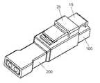
- FIG. 1is a perspective view of a connector assembly according to the invention
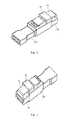
- FIG. 2is another perspective view of the connector assembly
- FIG. 3is a side view of the connector assembly
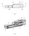
- FIG. 4is a sectional perspective view of the connector assembly
- FIG. 5is another sectional perspective view of the connector assembly
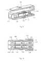
- FIG. 6is a sectional top view of the connector assembly
- FIG. 7is another perspective view of the connector assembly
- FIG. 8is a perspective view of a plug connector of the connector assembly
- FIG. 9is a sectional perspective view of the plug connector
- FIG. 10is a sectional top view of the plug connector.
- FIG. 11is a sectional top view of a receptacle connector of the connector assembly.
- FIGS. 1, 2 , and 7A connector assembly according to the invention is shown generally in FIGS. 1, 2 , and 7 .
- the connector assemblycomprises a plug connector 100 connected to a plurality of first wires 300 and a receptacle connector 200 mating with the plug connector 100 connected to a plurality of second wires 400 .
- the plug connector 100is mated with the receptacle connector 200
- the plurality of first wires 300 and the plurality of second wires 400are electrically connected with each other.
- either the plug connector 100 or the receptacle connector 200may be referred to as a connector and the other referred to as a mating connector.
- the plug connector 100is shown in FIGS. 8-10 .
- the plug connector 100includes a first housing 11 , a pair of first conductive terminals 12 , and a sealing member 13 .
- the first housing 11is made of an insulative material such as plastic and, as shown in FIGS. 9 and 10 , has a pair of first receiving passages 111 extending through the first housing 11 in an insertion direction of the first wire 300 and a plug portion 112 .
- Each first receiving passage 111has a first insertion port 113 disposed at an end of the first receiving passage 111 in the insertion direction.
- the plug portion 112has a cantilevered arm 15 extending in the insertion direction of the first wire 300 outside of the first housing 11 .
- the cantilevered arm 15is integrally connected with the first housing 11 and has an L-shape.
- a latch 151is disposed on an outer side of the cantilevered arm 15 .
- a second sealing member 14is disposed around an outer surface of the plug portion 112 .
- the first sealing member 13is made of a material such as rubber and, as shown in FIG. 10 , is mounted at a position adjacent the first insertion port 113 ; in the shown embodiment, the first sealing member 13 is mounted in the first insertion port 113 .
- the first wire 300is inserted into the first receiving passage 111 through the first insertion port 113 , and the first sealing member 13 has at least one wire receiving passageway 131 through which the first wire 300 passes.
- the first sealing member 13forms a seal with the first wire 300 to prevent foreign moisture from entering the first receiving passage 111 through the first insertion port 113 .
- the first sealing member 13has at least one ring shaped protrusion 132 around an outer circumferential surface of the first sealing member 13 , and correspondingly, the first receiving passage 111 , as shown in FIG. 9 , has at least one ring shaped groove 1111 around an inner circumferential surface of the first receiving passage 111 .
- the protrusions 132 of the first sealing member 13engage the grooves 1111 of the first receiving passage 111 , sealing the first sealing member 13 and the first receiving passage 111 .
- the first sealing member 13has at least one ring shaped groove around an outer circumferential surface of the first sealing member 13 , and correspondingly, the receiving passage 111 has at least one ring shaped protrusion around an inner circumferential surface of the receiving passage 111 ; the groove of the first sealing member 13 engaging the protrusion of the first receiving passage 111 .
- At least two sealing rings 133are disposed on an inner wall of the first wire receiving passageway 131 of the first sealing member 13 and project radially inwardly.
- a receiving groove 134is disposed between the adjacent sealing rings 133 .
- a minimum inner diameter of the sealing ring 133is less than an outer diameter of the first wire 300
- a maximum inner diameter of the receiving groove 134is greater than an outer diameter of the first wire 300 .
- the sealing ring 133maintains good sealing with the first wire 300 and foreign matter such as moisture entering through the outer sealing ring 133 accumulates in the receiving groove 134 , preventing the moisture from further entering the first receiving passage 111 .
- the first conductive terminals 12are received in the two first receiving passages 111 of the first housing 11 , respectively.
- Each first conductive terminal 12has a flat body 121 , a contact portion 122 , and a pair of crimps 123 .
- the contact portion 122extends from the body 121 and has a pair of clamping contact arms 1221 obliquely extending toward each other from the body 121 .
- the pair of crimps 123are disposed on the body 121 and crimp the first wire 300 inserted through the wire receiving passageway 131 of the first sealing member 13 , so that the first wire 300 is electrically connected to the first conductive terminal 12 .
- Each first conductive terminal 12has a stop 124 formed on the body 121 at a position proximate to the contact portion 122 . The stop 124 limits an insertion length of the first wire 300 .
- the receptacle connector 200is shown in FIGS. 5, 6, and 11 .
- the receptacle connector 200includes a second housing 21 , a pair of second conductive terminals 22 , and a third sealing member 23 .
- the second housing 21is made of an insulative material such as plastic and, as shown in FIG. 11 , has a pair of second receiving passages 211 extending through the second housing 21 in an insertion direction of the second wire 400 and a receptacle portion 212 receiving the plug portion 112 of the plug connector 100 .
- Each second receiving passage 211has a second insertion port 213 disposed at an end of the second receiving passage 211 in the insertion direction.
- the third sealing member 23is made of a material such as rubber and, as shown in FIG. 11 , is mounted in the second insertion port 213 of the second receiving passage 211 .
- the second wire 400is inserted into the second receiving passage 211 through the second insertion port 213 , and the third sealing member 23 has at least one wire receiving passageway 231 through which the second wire 400 passes.
- the third sealing member 23forms a seal with the second wire 400 to prevent foreign moisture from entering the second receiving passage 211 through the second insertion port 213 .
- the third sealing member 23has at least one ring shaped protrusion 232 around an outer circumferential surface of the third sealing member 23 , and correspondingly, the second receiving passage 211 has at least one ring shaped groove around an inner circumferential surface of the receiving passage 211 .
- the protrusion 232 of the third sealing member 23engages the groove of the second receiving passage 211 , sealing the third sealing member 23 and the second receiving passage 211 .
- At least two sealing rings 233 projecting radially inwardlyare disposed on an inner wall of the wire receiving passageway 231 .
- Receiving grooves 234are disposed between the sealing rings 233 .
- a minimum inner diameter of the sealing ring 233is less than an outer diameter of the second wire 400 , and the maximum inner diameter of the receiving groove 234 is larger than the outer diameter of the second wire 400 .
- the sealing ring 233maintains good sealing with the second wire 400 and foreign matter such as moisture entering through the outer sealing ring 233 accumulates in the receiving groove 234 , preventing the moisture from further entering into the second receiving passage 211 .
- the first receiving passage 111 of the plug connector 100has the same structure in the first insertion port 113 as that in the second insertion port 213 of the second receiving passage 211 of the receptacle connector 200 .
- the first sealing member 13has the same structure as that of the third sealing member 23 .
- the two second conductive terminals 22are received in the two second receiving passages 211 of the second housing 21 , respectively, to be electrically connected with the first conductive terminals 12 of the plug connector 100 .
- Each of the second conductive terminals 22has a flat body 221 , a contact portion 222 and a pair of crimps 223 .
- the contact portion 222has a pair of clamped contact arms 2221 extending from the body 221 parallel to one another to be clamped between the clamping contact arms 1221 of the plug connector 100 . Free ends 2222 of the clamped contact arms 2221 are bent inwardly towards to each other, so as to maintain a certain elasticity.
- the pair of crimps 223are disposed on the body 221 to crimp the second wire 400 inserted through the wire receiving passageway 231 of the third sealing member 23 , so that the second wire 400 is electrically connected to the second conductive terminal 22 .
- Each of the second conductive terminals 22has a stop 224 formed on the body 221 at a position proximate to the contact portion 222 .
- the stop 224limits an insertion length of the second wire 400 .
- a positioning frame 25is disposed on the second housing 21 .
- a protrusion 24is disposed on a side of the positioning frame 25 spaced apart from the second insertion port 213 of the second receiving passage 211 .
- the plug connector 100is matable with the receptacle connector 200 as shown in FIGS. 1-7 .
- the cantilevered arm 15 of the plug connector 100passes through the positioning frame 25 , and the latch 151 of the cantilevered arm 15 abuts against the positioning frame 25 .
- An end of the cantilevered arm 15abuts against the protrusion portion 24 , preventing the latch 151 from being disengaged from the positioning frame 25 .
- a portion of the cantilevered arm 15 between the positioning frame 25 and the protrusion portion 24is pressed such that the cantilevered arm 15 is bent downwardly.
- the latch 151 of the cantilevered arm 15then separated from the positioning frame 25 , permitting removal of the plug connector 100 from the receptacle connector 200 .
- the contact arms 1221 of the contact portion 122 of the plug connector 100crimp the contact arms 2221 of the contact portion 222 of the receptacle connector 200 , forming and maintaining an electrical connection between the first conductive terminal 12 and the second conductive terminal 22 .
- An electrical connection between the first conductive terminal 12 and the second conductive terminal 22electrically connects the first wires 300 and the second wires 400 .
- the contact portion 222 of the receptacle connector 200has the crimping contact arms while the contact portion 122 of the plug connector 100 has the crimped contact arms.
- the first sealing member 13is disposed at the first insertion port 113 of the plug connector 100 , an outer wall of the first wire 300 tightly engages with an inner wall of the first insertion port 113 to prevent foreign moisture from entering the first receiving passage 111 through the first insertion port 113 .
- the third sealing member 23is disposed at the second insertion port 213 of the receptacle connector 200 , an outer wall of the second wire 400 tightly engages with an inner wall of the second insertion port 213 to prevent foreign moisture from entering the second receiving passage 211 through the second insertion port 213 .
- the second sealing member 14is squeezed between an outer wall of the plug portion 112 and an inner wall of the receptacle portion 212 to form a seal between the outer wall of the plug portion 112 and the inner wall of the receptacle portion 212 .
- Moisturethus cannot enter the first receiving passage 111 and the second receiving passage 211 through the plug portion 112 of the plug connector 100 and the receptacle portion 212 of the receptacle connector 200 .
- the first conductive terminal 12 in the first housing 11 and the second conductive terminal 22 in the second housing 21are in an enclosed space where the foreign matter such as moisture cannot contact the first and second conductive terminals 12 , 22 , maintaining a good electrical connection between the first and second conductive terminals 12 , 22 .
- the plug connector 100 and receptacle connector 200each have two receiving passages 111 , 211 and two conductive terminals 12 , 22 connecting to two wires 300 , 400 , respectively.
- the number of receiving passages 111 , 211 , conductive terminals 12 , 22 , and wires 300 , 400may vary within the scope of the invention.
Landscapes
- Connector Housings Or Holding Contact Members (AREA)
Abstract
Description
Claims (19)
Applications Claiming Priority (3)
| Application Number | Priority Date | Filing Date | Title |
|---|---|---|---|
| CN201621057297.6UCN206610949U (en) | 2016-09-14 | 2016-09-14 | Connector and connector assembly for connecting wire |
| CN201621057297.6 | 2016-09-14 | ||
| CN201621057297U | 2016-09-14 |
Publications (2)
| Publication Number | Publication Date |
|---|---|
| US20180076562A1 US20180076562A1 (en) | 2018-03-15 |
| US10468813B2true US10468813B2 (en) | 2019-11-05 |
Family
ID=60170815
Family Applications (1)
| Application Number | Title | Priority Date | Filing Date |
|---|---|---|---|
| US15/704,408ActiveUS10468813B2 (en) | 2016-09-14 | 2017-09-14 | Connector for connecting wire and connector assembly |
Country Status (2)
| Country | Link |
|---|---|
| US (1) | US10468813B2 (en) |
| CN (1) | CN206610949U (en) |
Families Citing this family (4)
| Publication number | Priority date | Publication date | Assignee | Title |
|---|---|---|---|---|
| CN110011110B (en)* | 2018-01-05 | 2024-10-29 | 泰科电子(上海)有限公司 | Plug-in type wire-to-wire connector |
| CN108832389B (en)* | 2018-05-31 | 2020-03-24 | 番禺得意精密电子工业有限公司 | Electric connector combination |
| DE102018208721A1 (en)* | 2018-06-04 | 2019-12-05 | BSH Hausgeräte GmbH | Electric power cord with a sealing lip |
| CN109586118A (en)* | 2018-12-05 | 2019-04-05 | 东莞市鼎通精密五金股份有限公司 | A kind of high speed communication connector reducing cross-interference issue |
Citations (16)
| Publication number | Priority date | Publication date | Assignee | Title |
|---|---|---|---|---|
| US4605272A (en)* | 1978-08-24 | 1986-08-12 | Reynolds Industries, Inc. | High voltage electrical connector |
| US4973266A (en)* | 1988-08-09 | 1990-11-27 | Dill Products Incorporated | Combined terminal secondary lock and seal |
| US4983344A (en)* | 1988-12-16 | 1991-01-08 | Amp Incorporated | Method for injection molding a sealed connector assembly |
| US4986764A (en)* | 1989-10-31 | 1991-01-22 | Amp Incorporated | High voltage lead assembly and connector |
| US5351973A (en)* | 1992-01-31 | 1994-10-04 | Sumitomo Wiring Systems, Ltd. | Rubber seal for waterproof connector |
| US5580266A (en)* | 1995-03-10 | 1996-12-03 | The Whitaker Corporation | High voltage low current connector interface |
| US5626486A (en)* | 1995-03-10 | 1997-05-06 | The Whitaker Corporation | High voltage low current connector interface with compressible terminal site seal |
| US6039603A (en)* | 1993-06-14 | 2000-03-21 | Sumitomo Wiring Systems, Ltd. | Rubber plug for waterproof connector |
| US6336821B1 (en)* | 1999-05-26 | 2002-01-08 | Kitani Electric Co., Ltd. | Connector for use in solar generator |
| US6641421B1 (en)* | 2002-09-09 | 2003-11-04 | Reynolds Industries, Inc. | High-voltage electrical connector and related method |
| US7114991B2 (en)* | 2004-04-28 | 2006-10-03 | Tyco Electronics Amp K.K | Waterproof connector sealing member and waterproof connector |
| US7273395B2 (en)* | 2004-11-11 | 2007-09-25 | Tyco Electronics Amp K.K. | Waterproof connector and seal member |
| US7762842B2 (en)* | 2005-04-11 | 2010-07-27 | Fci | Grommet for electrical connector, and electrical connector comprising such a grommet |
| US8241061B2 (en)* | 2006-01-19 | 2012-08-14 | Fci Automotive Holding | Obturator for a compartment of a junction unit and junction unit equipped with such a obturator |
| US8337240B2 (en)* | 2008-12-12 | 2012-12-25 | Tyco Electronics Amp Gmbh | High-current plug-in connector |
| US9478882B1 (en)* | 2015-05-15 | 2016-10-25 | Google Inc. | Hazard detector electrical connector for easy user manipulation and atmospheric isolation |
- 2016
- 2016-09-14CNCN201621057297.6Upatent/CN206610949U/enactiveActive
- 2017
- 2017-09-14USUS15/704,408patent/US10468813B2/enactiveActive
Patent Citations (16)
| Publication number | Priority date | Publication date | Assignee | Title |
|---|---|---|---|---|
| US4605272A (en)* | 1978-08-24 | 1986-08-12 | Reynolds Industries, Inc. | High voltage electrical connector |
| US4973266A (en)* | 1988-08-09 | 1990-11-27 | Dill Products Incorporated | Combined terminal secondary lock and seal |
| US4983344A (en)* | 1988-12-16 | 1991-01-08 | Amp Incorporated | Method for injection molding a sealed connector assembly |
| US4986764A (en)* | 1989-10-31 | 1991-01-22 | Amp Incorporated | High voltage lead assembly and connector |
| US5351973A (en)* | 1992-01-31 | 1994-10-04 | Sumitomo Wiring Systems, Ltd. | Rubber seal for waterproof connector |
| US6039603A (en)* | 1993-06-14 | 2000-03-21 | Sumitomo Wiring Systems, Ltd. | Rubber plug for waterproof connector |
| US5580266A (en)* | 1995-03-10 | 1996-12-03 | The Whitaker Corporation | High voltage low current connector interface |
| US5626486A (en)* | 1995-03-10 | 1997-05-06 | The Whitaker Corporation | High voltage low current connector interface with compressible terminal site seal |
| US6336821B1 (en)* | 1999-05-26 | 2002-01-08 | Kitani Electric Co., Ltd. | Connector for use in solar generator |
| US6641421B1 (en)* | 2002-09-09 | 2003-11-04 | Reynolds Industries, Inc. | High-voltage electrical connector and related method |
| US7114991B2 (en)* | 2004-04-28 | 2006-10-03 | Tyco Electronics Amp K.K | Waterproof connector sealing member and waterproof connector |
| US7273395B2 (en)* | 2004-11-11 | 2007-09-25 | Tyco Electronics Amp K.K. | Waterproof connector and seal member |
| US7762842B2 (en)* | 2005-04-11 | 2010-07-27 | Fci | Grommet for electrical connector, and electrical connector comprising such a grommet |
| US8241061B2 (en)* | 2006-01-19 | 2012-08-14 | Fci Automotive Holding | Obturator for a compartment of a junction unit and junction unit equipped with such a obturator |
| US8337240B2 (en)* | 2008-12-12 | 2012-12-25 | Tyco Electronics Amp Gmbh | High-current plug-in connector |
| US9478882B1 (en)* | 2015-05-15 | 2016-10-25 | Google Inc. | Hazard detector electrical connector for easy user manipulation and atmospheric isolation |
Also Published As
| Publication number | Publication date |
|---|---|
| US20180076562A1 (en) | 2018-03-15 |
| CN206610949U (en) | 2017-11-03 |
Similar Documents
| Publication | Publication Date | Title |
|---|---|---|
| US3787796A (en) | Low cost sealed connector and method of making same | |
| US4713021A (en) | Sealed electrical connector and method of using same | |
| US8231408B2 (en) | Connector | |
| US10468813B2 (en) | Connector for connecting wire and connector assembly | |
| JP6259517B2 (en) | System with multiple plug-in connectors and multiple plug-in connectors | |
| US9070998B2 (en) | High speed electrical contact assembly | |
| JPS5826469A (en) | Electric connector | |
| US4674807A (en) | Shielded connector | |
| CN115425449A (en) | Crush rib housing for positive lock receptacle | |
| EP2161788A1 (en) | Connector assembly having a plurality of discrete components | |
| CN104078790B (en) | Female connector | |
| CN110011110B (en) | Plug-in type wire-to-wire connector | |
| US9466913B2 (en) | Car charging connector | |
| US20200021057A1 (en) | Electrical connector which accepts different seal configurations | |
| CN108281834B (en) | Connector socket and connector | |
| CN104247156B (en) | Insulation body of plug-in connector | |
| US9515415B1 (en) | Strain relief cable insert | |
| CN206610919U (en) | Connector for connection cable | |
| US10553963B1 (en) | Insulation crimp with lead-in projection | |
| CN103843200B (en) | Electrical connector system and method of making same | |
| KR101283620B1 (en) | Insert type joining structure of connector shield | |
| US7070440B1 (en) | Coaxial cable insulation displacement connector | |
| CN110391532B (en) | Connector | |
| CN101820110A (en) | Cable connector | |
| US9774103B2 (en) | Radial termination system for a communication connector |
Legal Events
| Date | Code | Title | Description |
|---|---|---|---|
| AS | Assignment | Owner name:TYCO ELECTRONICS (SHANGHAI) CO. LTD., CHINA Free format text:ASSIGNMENT OF ASSIGNORS INTEREST;ASSIGNORS:ZHANG, WEI;SHI, MING;FU, XIAOZHI;AND OTHERS;REEL/FRAME:043591/0066 Effective date:20170901 | |
| FEPP | Fee payment procedure | Free format text:ENTITY STATUS SET TO UNDISCOUNTED (ORIGINAL EVENT CODE: BIG.); ENTITY STATUS OF PATENT OWNER: LARGE ENTITY | |
| AS | Assignment | Owner name:TYCO ELECTRONICS (SHANGHAI) CO. LTD., CHINA Free format text:ASSIGNMENT OF ASSIGNORS INTEREST;ASSIGNOR:XU, XIANG;REEL/FRAME:044386/0936 Effective date:20171213 | |
| STPP | Information on status: patent application and granting procedure in general | Free format text:NON FINAL ACTION MAILED | |
| STPP | Information on status: patent application and granting procedure in general | Free format text:RESPONSE TO NON-FINAL OFFICE ACTION ENTERED AND FORWARDED TO EXAMINER | |
| STPP | Information on status: patent application and granting procedure in general | Free format text:NOTICE OF ALLOWANCE MAILED -- APPLICATION RECEIVED IN OFFICE OF PUBLICATIONS | |
| STPP | Information on status: patent application and granting procedure in general | Free format text:PUBLICATIONS -- ISSUE FEE PAYMENT VERIFIED | |
| STCF | Information on status: patent grant | Free format text:PATENTED CASE | |
| MAFP | Maintenance fee payment | Free format text:PAYMENT OF MAINTENANCE FEE, 4TH YEAR, LARGE ENTITY (ORIGINAL EVENT CODE: M1551); ENTITY STATUS OF PATENT OWNER: LARGE ENTITY Year of fee payment:4 |