US10466695B2 - User interaction paradigms for a flying digital assistant - Google Patents
User interaction paradigms for a flying digital assistantDownload PDFInfo
- Publication number
- US10466695B2 US10466695B2US15/791,230US201715791230AUS10466695B2US 10466695 B2US10466695 B2US 10466695B2US 201715791230 AUS201715791230 AUS 201715791230AUS 10466695 B2US10466695 B2US 10466695B2
- Authority
- US
- United States
- Prior art keywords
- uav
- image capture
- fda
- mobile device
- pmd
- Prior art date
- Legal status (The legal status is an assumption and is not a legal conclusion. Google has not performed a legal analysis and makes no representation as to the accuracy of the status listed.)
- Active
Links
Images


Classifications
- G—PHYSICS
- G05—CONTROLLING; REGULATING
- G05D—SYSTEMS FOR CONTROLLING OR REGULATING NON-ELECTRIC VARIABLES
- G05D1/00—Control of position, course, altitude or attitude of land, water, air or space vehicles, e.g. using automatic pilots
- G05D1/0011—Control of position, course, altitude or attitude of land, water, air or space vehicles, e.g. using automatic pilots associated with a remote control arrangement
- G05D1/0038—Control of position, course, altitude or attitude of land, water, air or space vehicles, e.g. using automatic pilots associated with a remote control arrangement by providing the operator with simple or augmented images from one or more cameras located onboard the vehicle, e.g. tele-operation
- B—PERFORMING OPERATIONS; TRANSPORTING
- B64—AIRCRAFT; AVIATION; COSMONAUTICS
- B64C—AEROPLANES; HELICOPTERS
- B64C39/00—Aircraft not otherwise provided for
- B—PERFORMING OPERATIONS; TRANSPORTING
- B64—AIRCRAFT; AVIATION; COSMONAUTICS
- B64C—AEROPLANES; HELICOPTERS
- B64C39/00—Aircraft not otherwise provided for
- B64C39/02—Aircraft not otherwise provided for characterised by special use
- B64C39/024—Aircraft not otherwise provided for characterised by special use of the remote controlled vehicle type, i.e. RPV
- B—PERFORMING OPERATIONS; TRANSPORTING
- B64—AIRCRAFT; AVIATION; COSMONAUTICS
- B64U—UNMANNED AERIAL VEHICLES [UAV]; EQUIPMENT THEREFOR
- B64U10/00—Type of UAV
- B64U10/10—Rotorcrafts
- B64U10/13—Flying platforms
- B64U10/14—Flying platforms with four distinct rotor axes, e.g. quadcopters
- B—PERFORMING OPERATIONS; TRANSPORTING
- B64—AIRCRAFT; AVIATION; COSMONAUTICS
- B64U—UNMANNED AERIAL VEHICLES [UAV]; EQUIPMENT THEREFOR
- B64U30/00—Means for producing lift; Empennages; Arrangements thereof
- B64U30/20—Rotors; Rotor supports
- B—PERFORMING OPERATIONS; TRANSPORTING
- B64—AIRCRAFT; AVIATION; COSMONAUTICS
- B64U—UNMANNED AERIAL VEHICLES [UAV]; EQUIPMENT THEREFOR
- B64U50/00—Propulsion; Power supply
- B64U50/10—Propulsion
- B64U50/19—Propulsion using electrically powered motors
- G—PHYSICS
- G05—CONTROLLING; REGULATING
- G05D—SYSTEMS FOR CONTROLLING OR REGULATING NON-ELECTRIC VARIABLES
- G05D1/00—Control of position, course, altitude or attitude of land, water, air or space vehicles, e.g. using automatic pilots
- G05D1/0011—Control of position, course, altitude or attitude of land, water, air or space vehicles, e.g. using automatic pilots associated with a remote control arrangement
- G05D1/0016—Control of position, course, altitude or attitude of land, water, air or space vehicles, e.g. using automatic pilots associated with a remote control arrangement characterised by the operator's input device
- G—PHYSICS
- G05—CONTROLLING; REGULATING
- G05D—SYSTEMS FOR CONTROLLING OR REGULATING NON-ELECTRIC VARIABLES
- G05D1/00—Control of position, course, altitude or attitude of land, water, air or space vehicles, e.g. using automatic pilots
- G05D1/0011—Control of position, course, altitude or attitude of land, water, air or space vehicles, e.g. using automatic pilots associated with a remote control arrangement
- G05D1/0044—Control of position, course, altitude or attitude of land, water, air or space vehicles, e.g. using automatic pilots associated with a remote control arrangement by providing the operator with a computer generated representation of the environment of the vehicle, e.g. virtual reality, maps
- G—PHYSICS
- G05—CONTROLLING; REGULATING
- G05D—SYSTEMS FOR CONTROLLING OR REGULATING NON-ELECTRIC VARIABLES
- G05D1/00—Control of position, course, altitude or attitude of land, water, air or space vehicles, e.g. using automatic pilots
- G05D1/0094—Control of position, course, altitude or attitude of land, water, air or space vehicles, e.g. using automatic pilots involving pointing a payload, e.g. camera, weapon, sensor, towards a fixed or moving target
- G—PHYSICS
- G05—CONTROLLING; REGULATING
- G05D—SYSTEMS FOR CONTROLLING OR REGULATING NON-ELECTRIC VARIABLES
- G05D1/00—Control of position, course, altitude or attitude of land, water, air or space vehicles, e.g. using automatic pilots
- G05D1/20—Control system inputs
- G05D1/22—Command input arrangements
- G05D1/221—Remote-control arrangements
- G05D1/222—Remote-control arrangements operated by humans
- G05D1/223—Command input arrangements on the remote controller, e.g. joysticks or touch screens
- G05D1/2232—Touch screens
- G—PHYSICS
- G05—CONTROLLING; REGULATING
- G05D—SYSTEMS FOR CONTROLLING OR REGULATING NON-ELECTRIC VARIABLES
- G05D1/00—Control of position, course, altitude or attitude of land, water, air or space vehicles, e.g. using automatic pilots
- G05D1/20—Control system inputs
- G05D1/22—Command input arrangements
- G05D1/221—Remote-control arrangements
- G05D1/222—Remote-control arrangements operated by humans
- G05D1/224—Output arrangements on the remote controller, e.g. displays, haptics or speakers
- G05D1/2244—Optic
- G05D1/2245—Optic providing the operator with a purely computer-generated representation of the environment of the vehicle, e.g. virtual reality
- G—PHYSICS
- G05—CONTROLLING; REGULATING
- G05D—SYSTEMS FOR CONTROLLING OR REGULATING NON-ELECTRIC VARIABLES
- G05D1/00—Control of position, course, altitude or attitude of land, water, air or space vehicles, e.g. using automatic pilots
- G05D1/20—Control system inputs
- G05D1/22—Command input arrangements
- G05D1/221—Remote-control arrangements
- G05D1/222—Remote-control arrangements operated by humans
- G05D1/224—Output arrangements on the remote controller, e.g. displays, haptics or speakers
- G05D1/2244—Optic
- G05D1/2247—Optic providing the operator with simple or augmented images from one or more cameras
- G—PHYSICS
- G06—COMPUTING OR CALCULATING; COUNTING
- G06F—ELECTRIC DIGITAL DATA PROCESSING
- G06F3/00—Input arrangements for transferring data to be processed into a form capable of being handled by the computer; Output arrangements for transferring data from processing unit to output unit, e.g. interface arrangements
- G06F3/01—Input arrangements or combined input and output arrangements for interaction between user and computer
- G06F3/048—Interaction techniques based on graphical user interfaces [GUI]
- G06F3/0487—Interaction techniques based on graphical user interfaces [GUI] using specific features provided by the input device, e.g. functions controlled by the rotation of a mouse with dual sensing arrangements, or of the nature of the input device, e.g. tap gestures based on pressure sensed by a digitiser
- G06F3/0488—Interaction techniques based on graphical user interfaces [GUI] using specific features provided by the input device, e.g. functions controlled by the rotation of a mouse with dual sensing arrangements, or of the nature of the input device, e.g. tap gestures based on pressure sensed by a digitiser using a touch-screen or digitiser, e.g. input of commands through traced gestures
- G06F3/04883—Interaction techniques based on graphical user interfaces [GUI] using specific features provided by the input device, e.g. functions controlled by the rotation of a mouse with dual sensing arrangements, or of the nature of the input device, e.g. tap gestures based on pressure sensed by a digitiser using a touch-screen or digitiser, e.g. input of commands through traced gestures for inputting data by handwriting, e.g. gesture or text
- H—ELECTRICITY
- H04—ELECTRIC COMMUNICATION TECHNIQUE
- H04N—PICTORIAL COMMUNICATION, e.g. TELEVISION
- H04N23/00—Cameras or camera modules comprising electronic image sensors; Control thereof
- H04N23/60—Control of cameras or camera modules
- H04N23/66—Remote control of cameras or camera parts, e.g. by remote control devices
- H04N23/661—Transmitting camera control signals through networks, e.g. control via the Internet
- H—ELECTRICITY
- H04—ELECTRIC COMMUNICATION TECHNIQUE
- H04N—PICTORIAL COMMUNICATION, e.g. TELEVISION
- H04N23/00—Cameras or camera modules comprising electronic image sensors; Control thereof
- H04N23/60—Control of cameras or camera modules
- H04N23/695—Control of camera direction for changing a field of view, e.g. pan, tilt or based on tracking of objects
- H—ELECTRICITY
- H04—ELECTRIC COMMUNICATION TECHNIQUE
- H04N—PICTORIAL COMMUNICATION, e.g. TELEVISION
- H04N5/00—Details of television systems
- B64C2201/027—
- B64C2201/042—
- B64C2201/127—
- B64C2201/141—
- B—PERFORMING OPERATIONS; TRANSPORTING
- B64—AIRCRAFT; AVIATION; COSMONAUTICS
- B64U—UNMANNED AERIAL VEHICLES [UAV]; EQUIPMENT THEREFOR
- B64U2101/00—UAVs specially adapted for particular uses or applications
- B64U2101/30—UAVs specially adapted for particular uses or applications for imaging, photography or videography
- B—PERFORMING OPERATIONS; TRANSPORTING
- B64—AIRCRAFT; AVIATION; COSMONAUTICS
- B64U—UNMANNED AERIAL VEHICLES [UAV]; EQUIPMENT THEREFOR
- B64U2201/00—UAVs characterised by their flight controls
- B64U2201/10—UAVs characterised by their flight controls autonomous, i.e. by navigating independently from ground or air stations, e.g. by using inertial navigation systems [INS]
- B—PERFORMING OPERATIONS; TRANSPORTING
- B64—AIRCRAFT; AVIATION; COSMONAUTICS
- B64U—UNMANNED AERIAL VEHICLES [UAV]; EQUIPMENT THEREFOR
- B64U2201/00—UAVs characterised by their flight controls
- B64U2201/20—Remote controls
- G—PHYSICS
- G06—COMPUTING OR CALCULATING; COUNTING
- G06F—ELECTRIC DIGITAL DATA PROCESSING
- G06F2203/00—Indexing scheme relating to G06F3/00 - G06F3/048
- G06F2203/048—Indexing scheme relating to G06F3/048
- G06F2203/04808—Several contacts: gestures triggering a specific function, e.g. scrolling, zooming, right-click, when the user establishes several contacts with the surface simultaneously; e.g. using several fingers or a combination of fingers and pen
- H—ELECTRICITY
- H04—ELECTRIC COMMUNICATION TECHNIQUE
- H04N—PICTORIAL COMMUNICATION, e.g. TELEVISION
- H04N21/00—Selective content distribution, e.g. interactive television or video on demand [VOD]
- H04N21/40—Client devices specifically adapted for the reception of or interaction with content, e.g. set-top-box [STB]; Operations thereof
- H04N21/43—Processing of content or additional data, e.g. demultiplexing additional data from a digital video stream; Elementary client operations, e.g. monitoring of home network or synchronising decoder's clock; Client middleware
- H04N21/4302—Content synchronisation processes, e.g. decoder synchronisation
- H04N21/4307—Synchronising the rendering of multiple content streams or additional data on devices, e.g. synchronisation of audio on a mobile phone with the video output on the TV screen
Definitions
- the present disclosurerelates generally to methods and systems for the control of unmanned aerial vehicles (UAV) as platforms for the capture of images (including video). Specifically, the present disclosure relates to new paradigms for user interaction with and control of UAVs using a portable multifunction device such as smart phone.
- UAVunmanned aerial vehicles
- Unmanned aerial vehiclesare increasingly being used as platforms for taking images and video from the air.
- a number of UAV systemsare currently available that provide for image and video capture and remote control from a device on the ground.
- currently available systemsrequire piloting using direct control of the UAV similar to other fixed wing or rotor craft.
- controlby directly adjusting the pitch, roll, yaw, and power of the UAV, for example, using common control inputs such as a joystick and throttle control.
- While effective to a degree, such control systemsrequire expertise on the part of the remote pilot and are prone to crashes caused by pilot error. Instead, methods and systems are needed that provide for indirect control of an otherwise autonomous UAV using new intuitive and user friendly paradigms for interaction.
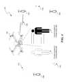
- FIG. 1is illustration of an example Flying Digital Assistant (“FDA”) 100 controlled by a user via a portable multifunction device (PMD), according to some embodiments;
- FDAFlying Digital Assistant
- PMDportable multifunction device
- FIG. 2is a conceptual diagram of a localization and navigation system for guiding navigation and image/video capture by an FDA, according to some embodiments;
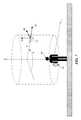
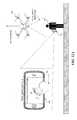
- FIG. 3is a conceptual diagram of system for estimating the position and/or orientation of an FDA using a network of phased array wireless transceivers, according to some embodiments;
- FIG. 4is a conceptual diagram of an example system passive localization of target object, according to some embodiments.
- FIGS. 5A-5Billustrate example methods for estimating the position and/or orientation of objects using computer vision technology, according to some embodiments
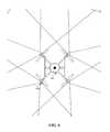
- FIG. 6is a high-level illustration of an omnidirectional camera ball, according to some embodiments.
- FIGS. 7-8illustrate various examples for understanding and describing the motion of an FDA relative to a point of reference
- FIGS. 9A-9Billustrate a “virtual camera” paradigm for user interaction with an FDA, according to some embodiments
- FIG. 9Cis a flow chart illustrating an example method for implementing the “virtual camera” user interaction paradigm, according to some embodiments.
- FIG. 10Aillustrates a “drawn path” paradigm for user interaction with an FDA, according to some embodiments
- FIG. 10Billustrates a “focus point” paradigm for user interaction with an FDA, according to some embodiments
- FIG. 10Cillustrates a “preset patterns” paradigm for user interaction with an FDA, according to some embodiments
- FIG. 10Dis a flow diagram of an example method for controlling an aerial view of a physical environment from an FDA using a touch display of a PMD, according to some embodiments;
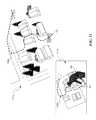
- FIG. 11illustrates a “scripted shot” paradigm for user interaction with an FDA, according to some embodiments
- FIGS. 12A-12Dillustrate a “multitouch cinematographer” paradigm for user interaction with an FDA, according to some embodiments
- FIG. 13is high level system diagram of components in an example FDA, according to some embodiments.
- FIG. 14is high level system diagram of components in an example PMD, according to some embodiments.
- FIG. 1is an illustration of a Flying Digital Assistant (“FDA”) 100 controlled by a user 102 via a portable multifunction device (“PMD”) 104 , according to some embodiments.
- an FDA 100may comprise a quadcopter “unmanned aerial vehicle” (UAV) or “drone.”
- UAVunmanned aerial vehicle
- terms such as “FDA,” “UAV,” “quadcopter,” and “drone”may be used interchangeably.
- propulsion and control surfaces 110e.g., powered rotors
- sensors for automated navigation and flight control 112e.g., an omni-directional camera ball—described in more detail herein
- audioe.g., a camera and microphone
- meansfor communicating with the PMD 104 , for example, via a wireless connection 116 .
- the FDA 100 shown in FIG. 1is an example embodiment, an FDA in accordance with the present teachings may include more or fewer components. Examples of an FDA and PMD are described in more detail in later sections.
- Various embodiments of the present teachingsallow a user 102 to control the capture of audio, images, and/or video through the use of an FDA 100 and a PMD 104 .
- the FDA 100may travel autonomously to capture audio, images, and/or video.
- the FDA 100may generally be conceptualized as an autonomous aerial camera rather than as a vehicle with an attached camera, and may therefor represent a paradigm shift in which cameras are understood. As will be described in more detail, an FDA similar to FDA 100 in FIG.
- a “magic wand” interfacein which an FDA follows the motion of a user's PMD as if magically attached to an invisible tether
- a multitouch cinematographer interfacein which image capture by the FDA is controlled via multitouch gestures applied by a user to a PMD
- scripted shotsin which the user may pre script shots by physically carrying an FDA or PMD through a scene, to name a few.
- FIG. 2is a high-level illustration of a localization and navigation system 200 , according to some embodiments, for guiding navigation and image/video capture by an FDA 100 .
- a relative position and/or pose (position+orientation) of the FDA 100a relative position and/or pose of the subject, and/or a relative position and/or pose of a PMD operated by a user 102 may be determined using one or more of the subsystems illustrated in FIG. 2 . Further, this relative pose data may be used by the FDA 100 to navigate and to track subjects for image and/or video capture.
- localization system 200may include an FDA 100 , a GPS system comprising multiple GPS satellites 202 , a cellular system comprising multiple cellular antennae 204 (with access to sources of localization data 206 ), a Wi-Fi system comprising multiple Wi-Fi routers 208 (with access to sources of localization data 206 ), and a portable multifunction device 104 operated by a user 102 .
- the FDA 100may comprise components including, but not limited to, an inertial measurement unit (IMU), a GPS receiver, multiple RF receivers and/or transceivers (e.g., cellular LTE, Wi-Fi), and one or more image capture devices.
- IMUinertial measurement unit
- an image capture devicemay be used to determine position and/or pose through the use of computer vision techniques and or optics-based collision detection and range finding. This is illustrated conceptually in FIG. 2 by the dotted line 214 .
- the PMD 104may comprise components including, but not limited to, an inertial measurement unit (IMU), a GPS receiver, multiple RF receivers and/or transceivers (e.g., cellular LTE, Wi-Fi), and an image capture device. Additional information on the components comprising a PMD 104 may be found under the section titled “Background on a Portable Multifunction Device,” and with reference to FIG. 14 .
- a relative position and/or pose (position+orientation) of the FDA 100 , a relative position and/or pose of the subject (e.g., user 102 ), and/or a relative position and/or pose of a PMD 104 operated by a user 102may be determined using one or more of the subsystems illustrated in FIG. 2 .
- a position on the globemay be determined for any device comprising a GPS receiver (e.g., the FDA 100 and/or the PMD 104 ). While GPS by itself in certain implementations may provide highly accurate global positioning it is generally is not capable of providing accurate information regarding orientation. Instead a technique of multiple inputs and multiple outputs (“MIMO”) (as illustrated in FIG. 2 ) may be used for localization, potentially in conjunction with other localization subsystems.
- MIMOmultiple inputs and multiple outputs
- a user 102is utilizing an autonomous FDA 100 via a PMD 104 to film herself overhead.
- a relative position and orientation of the FDA relative to the PMDmay be necessary.
- a relative position between the FDA and the PMDmay be determined using a GPS system to determine a global position of the FDA, a global position of the PMD and compare the two.
- a position relative to the known locations of antennaemay be determined for both the FDA and PMD using known positioning techniques.
- Some known positioning techniquesinclude those based on signal trilateration, for example, round trip time of arrival (RTT) in which a signal is sent and received by a signal transceiver and distance is calculated based on the elapsed time, received signal strength (RSS) in which the power levels of the transmitted signal and the received signals are analyzed and a distance determined based on a known propagation loss.
- RTTround trip time of arrival
- RSSreceived signal strength
- Other known positioning techniquesinclude those based on signal triangulation, for example, angle of arrival (AoA) in which angles of arriving signals are determined and through applied geometry a position determined.
- RF signal beamformingi.e., directional signal transmission using phased-shifted antenna arrays
- Beamformingmay be accomplished through the transmission of RF signals at different phases from spatially distributed antennas (a “phased antenna array”) such that constructive interference may occur at certain angles while destructive interference may occur at others, thereby resulting in a targeted directional RF signal field.
- a targeted fieldis illustrated conceptually in FIG. 2 by dotted lines 212 emanating from Wi-Fi routers 210 .
- an FDA 100 and/or PMD 104may include a phased array of Wi-Fi antenna and a relative position and/or pose may be calculated without the necessity for external existing Wi-Fi routers.
- the FDA 100 and/or PMD 104may transmit and/or receive a beamformed RF signal via a phased antenna array.
- the FDA 100 and/or PMD 104may then detect the phase differences and power levels of the respective incoming signals and calculate an AoA for the incoming signals. For example, according to FIG. 3 , the PMD 104 may determine an AoA of ⁇ 1 for the RF signals 302 transmitted by the FDA 100 .
- the FDA 100may determine an AoA of ⁇ 2 for the RF signals 304 transmitted by the PMD 104 .
- This AoA informationmay then be incorporated with information gathered by an IMU on the FDA 100 and/or PMD 104 (as well as other positioning data as described earlier) in order to infer a relative position and/pose between the FDA 100 and the PMD 104 .
- an array of Wi-Fi transmitters and signal monitorsmay be utilized for device-free passive localization of objects that are not transmitting signals (e.g., a human subject not carrying a PMD).
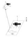
- FIG. 4illustrates an example system 400 for device-free passive localization of an object (e.g., a human subject).
- a human subject 402passes through a network of Wi-Fi transmitters 408 transmitting RF signals.
- the signal monitors 410e.g., standard wireless sniffers
- Such changes in the RF signal fieldmay be correlated to the presence of an object, its type, its orientation and its location.
- information gathered by device-free passive localization system 400may be fed wirelessly (e.g., via Wi-Fi connection 430 ) for to a nearby FDA 100 in order to inform its tracking of the human subject 402 .
- an inertial measurement unitmay be used to determine relative position and/or orientation.
- An IMUis a device that calculates a vehicle's velocity, orientation and gravitational forces using a combination of accelerometers and gyroscopes.
- an FDA 100 and/or PMD 104may include one or more IMUs.
- Using a method commonly referred to as “dead reckoning” an IMU (or associated systems)may calculate and track a predicted a current position based on a previously known position(s) using measured velocities and the time elapsed from the previously known position(s).
- an embodiment utilizing localization using an IMUmay include localization data from other sources (e.g., the GPS, Wi-Fi, and cellular systems described above) to continuously update the last known position and/or orientation of the object.
- a nonlinear estimation algorithmone embodiment being an “extended Kalman filter” may be applied to a series of measured positions and/or orientations to produce a real-time optimized prediction of the current position and/or orientation based on assumed uncertainties in the observed data. Kalman filters are commonly applied in the area of aircraft navigation, guidance, and controls.
- computer visionmay be used to determine a relative position and/or orientation of an FDA 100 , PMD 104 , and or any other object.
- the term, “computer vision” in this contextmay generally refer to the acquiring, processing, analyzing and understanding of captured images.
- an FDA 100may include an image capture device and computer vision capabilities.
- FDA 100may be programed to track a user 102 (or other physical object).
- an FDA 100may recognize the captured image as a user 102 (or other physical object) and may use the recognition information to perform aerial maneuvers by the FDA 100 to keep the user 102 (or physical object) in view, and/or may make adjustments to an image stabilization system (discussed in more detail herein) to keep the user 102 (or physical object) in view.
- an image stabilization systemdiscussed in more detail herein
- Relative position and/or orientationmay be determined through computer vision using a number of methods.
- an image capture device of the FDA 100may include two or more cameras. By comparing the captured image from two or more vantage points, a system employing computer vision may calculate a distance to a captured physical object. With the calculated distance as well as other position and/or orientation data for the FDA (e.g., data from GPS, Wi-Fi, Cellular, and/or IMU, as discussed above) a relative position and/or orientation may be determined between the FDA 100 and the captured physical object.
- position and/or orientation data for the FDAe.g., data from GPS, Wi-Fi, Cellular, and/or IMU, as discussed above
- an image capture device of FDA 100may be a single camera (i.e., a non-stereoscopic camera).
- computer vision algorithmsmay identify the presence of an object and identify the object as belonging to a known type with particular dimensions. For example, through computer vision, the object may be identified as an adult male human.
- FDA 100may predict a relative position and/or orientation of the object.
- FIG. 5Ashows a simplified diagram that illustrates how sensor data gathered by an IMU at a PMD 104 may be applied to sensor data gathered by an image capture device at an FDA 100 to determine position and/or orientation data of a physical object (e.g., a user 102 ).
- Outline 550represents the 2-dimensional image captured field of view at an FDA 100 .
- the field of viewincludes the image of a physical object (here user 102 ) moving from one position to another.
- FDA 100may determine a distance A traveled across the image capture field of view.
- the PMD 104carried by user 102 , may determine an actual distance B traveled by the user 102 based on measurements by internal sensors (e.g., the IMU) and an elapsed time.
- the FDA 100may then receive the sensor data and/or the distance B calculation from PMD 104 (e.g., via wireless RF signal). Correlating the difference between the observed distance A and the received distance B, FDA 100 may determine a distance D between FDA 100 and the physical object (user 102 ).
- a relative position and/or orientationmay be determined between the FDA 100 and the physical object (e.g., user 102 ).
- FIG. 5Billustrates the working concept behind visual odometry at a high level. A plurality of images is captured in sequence as a camera moves through space. Due to the movement of the camera, the images captured of the surrounding space change from frame to frame. In FIG. 5B , this is illustrated by initial image capture field of view 552 and a subsequent image capture field of view 554 captured as the camera has moved from a first position and orientation to a second position and orientation over an elapsed time.
- the cameramay capture real world physical objects, for example, the house 580 and/or the human subject (e.g., user) 102 .
- Computer vision techniquesare applied to the sequence of images to detect and match features of physical objects captured in the field of view of the camera. For example, in FIG. 5B , features such as the head of a human subject 102 or the corner of the chimney on the house 580 are identified, matched, and thereby tracked.
- sensor data from an IMUor accelerometer(s) or gyroscope(s) associated with the camera to the tracked features of the image capture, estimations may be made for the position and/or orientation of the camera over time.
- This techniquemay be applied at both the FDA 100 and PMD 104 to calculate the position and/or orientation of both systems. Further, by communicating the estimates between the systems (e.g., via a Wi-Fi connection) estimates may be calculated for the respective positions and/or orientations relative to each other. As previously mentioned position, orientation, and motion estimation based in part on sensor data from an on board IMU may introduce error propagation issues. As previously stated, optimization techniques may be applied to position, orientation, and motion estimations to counter such uncertainties. In some embodiments, a nonlinear estimation algorithm (one embodiment being an “extended Kalman filter”) may be applied to a series of measured positions and/or orientations to produce a real-time optimized prediction of the current position and/or orientation based on assumed uncertainties in the observed data.
- a nonlinear estimation algorithmone embodiment being an “extended Kalman filter”
- computer visionmay include remote sensing technologies such as laser illuminated detection and ranging (LIDAR or Lidar).
- LIDARlaser illuminated detection and ranging
- an FDA 100 equipped with LIDARmay emit one or more laser beams in a continuous scan up to 360 degrees in all directions around the FDA 100 .
- Light received by the FDA 100 as the laser beams reflect off physical objects in the surrounding physical worldmay be analyzed to construct a real time 3D computer model of the surrounding physical world.
- Such 3D modelsmay be analyzed to identify particular physical objects (e.g., a user 102 ) in the physical world for tracking.
- images captured by camerase.g., as described earlier
- the computer vision-aided localization and navigation system described abovemay calculate the position and/or pose of features in the physical world in addition to the position and/or pose of the FDA 100 and/or PMD 104 .
- the position of these featuresmay then be fed into the navigation system such that motion trajectories may be planned that avoid obstacles.
- the visual navigation algorithmsmay incorporate data from proximity sensors (e.g., electromagnetic, acoustic, and/or optics based) to estimate obstacle position with more accuracy. Further refinement may be possible with the use of stereoscopic computer vision with multiple cameras, as described earlier.
- the previously described relative position and/or orientation calculationsmay be performed by an FDA 100 , PMD 104 , remote computing device(s) (not shown in the figures), or any combination thereof.
- the localization system 200 of FIG. 2(including all of the associated subsystems as previously described) is only one example of a system for localization and navigation. Localization system 200 may have more or fewer components than shown, may combine two or more components, or a may have a different configuration or arrangement of the components. Some of the various components shown in FIGS. 2 through 4 may be implemented in hardware, software or a combination of both hardware and software, including one or more signal processing and/or application specific integrated circuits.
- an add-on modulemay comprise software and/or hardware components and may be functionally coupled to an existing unmanned aerial vehicle (UAV) thereby giving the existing UAV the functionality of an FDA according to the present teachings.
- an add-on modulemay transmit and receive data from a user's PMD, and may process and interpret commands and may talk to the existing UAV's flight controller an image capture device.
- the add-on modulemay further comprise its own image capture device with a computer vision controller.
- the add-on modulemay comprise any combination of software and/or hardware necessary to convert an existing UAV into an FDA in accordance with the present teachings.
- an add-on modulemay comprise the components within the dotted line boundary 1390 .
- an off-the-shelf PMDe.g., an iPhone®
- an add-on modulewhen functionally coupled to an existing UAV.
- the add-on modulemay communicate with the existing UAV wirelessly, via the same interface that a human pilot would with a wireless remote control.
- the add on modulemay be treated as another source of position data.
- the add on modulemay provide GPS-like position data even when no GPS is available, and in this way may effectively serve as a more reliable GPS receiver.
- FDA 100may comprise multiple high resolution image capture devices 602 (“cameras”) with spatial offsets from each other, thereby providing the capability to capture a full view of the world in all directions.
- the camerasmay be arranged such that at least two cameras are capable of viewing every angle, thereby allowing for 3D image/video capture and depth recovery (e.g., through computer vision algorithms) at every angle.
- each cameramay include a “fisheye” lens.
- FIG. 6shows a high-level illustration of the concept of multiple cameras with overlapping fields of view as represented by the dotted lines.
- FIG. 6is provided to illustrate the concept, but does not indicate a particular configuration or geometry as a limitation.
- an FDA in accordance with the present teachingsmay include more or fewer cameras.
- the position and orientation of each cameramay be calibrated to an onboard inertial measurement unit (IMU).
- IMUinertial measurement unit
- a monocular navigation algorithmmay be run for each camera paired with an on board IMU and as the relative position and orientation calibration is dialed in, stereo correspondence may be performed on observed primitives representing a pair of corresponding image features captured by a pair of cameras in order to provide a more robust estimation of distance to the objects.
- An FDA 100may include an image capture adjustment and stabilization system. Capturing images and video from a vehicle in motion (such as from an FDA 100 ) may lead to quality issues such as blur, shake, and disorientation. Image stabilization may generally refer to techniques used to counter these effects and produce a clear stable image even when captured by a vehicle in motion.
- a multi-axis mechanical gimbal devicemay, through the use of gyroscopes and mechanical actuators along two or more axis, physically stabilize an image capturing device (e.g., a camera) coupled to a mobile platform.
- an image capturing devicee.g., a camera
- An example of a multi-axis gimbal currently availableis the Freefly MoVI®.
- multi-axis mechanical gimbalsmay add significant mechanical and systems complexity as well as weight to a FDA 100 .
- captured digital imagesmay be digitally “stabilized” using digital image processing to manipulate the image.
- ParrotTMoffers a drone with a motionless 180 degree camera with a fisheye lens. Using post processing and crop filters may result in a “stabilized” image. While effective in certain implementations, full digital image stabilization may reduce image quality due to image sensor resolution limits, and in the case of using crop filters may require capturing more data than is necessary.
- an FDA 100may include a hybrid approach comprising a single axis mechanical gimbal along with real-time image processing (herein referred to as a “digital gimbal”).
- a single axis gimbal capable of adjusting the orientation of the image capture device in conjunction with the yaw control of the FDA 100 and digital image processingmay produce a full range or image capture from looking straight down from the FDA 100 to the ground to looking straight up from the FDA 100 to the sky while providing an effective minimum in overall system complexity.
- a single axis mechanical gimbalwould adjust the pitch of the image capture device. Adjusting pitch as opposed to roll or yaw, would allow for overall camera range of motion where the FDA 100 is implemented as a rotary vehicle, for example, a quadcopter (see Section titled “Background on Flying Digital Assistant” for additional information). This has to do with the way in which the flight of a quadcopter is controlled. Generally, a quadcopter is controlled by varying the orientation of its vertical axis. In other words, in a hover the quadcopter's vertical axis is perpendicular to the ground.
- utilizing a pitch gimbalgives maximum possible view range of motion since the yaw of the image capture device is easily controlled by adjusting the yaw of the quadcopter itself and the roll of the image capture device is easily controlled through digital image processing, for example, simple image rotation transforms.
- the FDA 100may maneuver according to an absolute fixed coordinate system.
- user inputs and gesturesmay correspond with an instruction to move to an absolute point in space.
- the FDA 100may also maneuver according to a coordinate system relative to a “point of reference.”
- the point of referencemay be defined as at or associated with a physical object in physical space.
- the point of referencemay be the PMD 104 through which the user 102 provides input.
- the point of referencemay also be another point in space which may be specified via the PMD 104 by clicking on a location of interest on a map or image.
- a user 102 viewing a live video feed from FDA 100 through the touch display of PMD 104may touch a point or select a displayed object to redefine the point of reference about which motion is defined.
- the defined point of referencemay be stationary (e.g., a building or physical marker) or may be in motion (e.g., a moving car).
- any motions by the FDA 100may be made relative to the car.
- the point of referenceis set to be a car moving at 25 mph, then a FDA 100 in “hover” would actually match the speed of the car while maintaining a constant position/orientation relative to the car. If the FDA 100 received input to move 10 feet in one direction, it would again do so relative to the car's position/orientation at any given moment.
- a relative coordinate systemmay simplify the motion calculations necessary to maneuver the FDA 100 . Further, controlled motions made relative to point of reference associated with the user 102 or PMD 104 may allow for more intuitive control of the FDA.
- FIGS. 7 and 8Illustrate at a high level how the motion of an FDA 100 controlled by the disclosed techniques may be calculated and/or described according to different coordinate systems.
- an FDA 100is be configured to maneuver according to a cylindrical polar coordinate system relative to a point of reference, for example, the user 102 or PMD 104 held by the user 102 .
- a detected input by the user 102 with the PMD 104may cause the FDA 100 to move along the normal tangent to an axial direction z.
- a particular input by the user 102 , via PMD 104may cause the FDA 100 to accelerate along basis directions êz and ê ⁇ , with no acceleration in the basis direction êr.
- FDA 100may travel along an invisible cylindrical plane at a constant radius R from user 102 .
- the usermay provide an input to accelerate the FDA 100 along basis direction êr while maintaining constant positions z and ⁇ .
- a user 102(while holding the button down on a touch screen display of a PMD 104 ) may slide their finger up or down. This may correspond to an acceleration by FDA 100 in the basis direction êr.
- an FDA 100may be configured to maneuver according to a spherical polar coordinate system. Similar to the example illustrated in FIG. 7 , an input provided by user 102 with the PMD 104 may cause the FDA 100 to accelerate along basis directions ê ⁇ and ê ⁇ , with no acceleration in basis direction êr. Accordingly, in response to the input, FDA 100 may travel along an invisible spherical plane at a constant radius R from user 102 . Also similarly, swiping up or down motion on the touch screen display of PMD 104 may cause FDA 100 to accelerate in basis direction êr.
- Calculations for the motion of the FDA 100 in the above described control configurationsmay be accomplished using relative or absolute coordinate system of any type (Cartesian, polar, cylindrical, etc.), although motion calculations based on an absolute coordinate system may be more processor intensive than if made relative to point of reference (e.g., user 102 or PMD 104 ).
- the cylindrical and polar coordinate systemsare used here for illustrative purposes to describe more clearly the way in which the FDA 100 may move relative to a reference point (e.g., the user 102 or PMD 104 ) using the above described techniques.
- calculation of maneuvers to be performed by the FDA 100may include implementation of a feed-forward control scheme.
- the motionmay be interpreted as a control input and recognized as fitting a model of one or more preset of historical control inputs.
- the recognized inputmay correspond to a predicted trajectory and stop point for FDA 100 .
- the FDA 100may begin a maneuver and midpoint along a predicted path, begin maneuvering to return to a hover. This will allow for smoother transitions between flight maneuvers.
- the FDA 100may capture images and or video using one or more on board optical sensors.
- image capturemay track the same point of reference used for calculating motion.
- the FDA 100may maneuver around the user 102 in response to gestures made by the user 102 with the PMD 104 , as described above.
- the FDA 100may adjust the orientation and/or processing of image capture device(s) (e.g., optical sensors) such that the point of reference (i.e., the user 102 ) remains centered in the field of view of the image capture device(s).
- Image capturemay be adjusted according to techniques previously described, for example, the a mechanical and/or a hybrid mechanical gimbal system linked to one or more cameras.
- FIGS. 9A-9Billustrate at a high level a “virtual camera” paradigm for user interaction with an FDA 100 , according to some embodiments.
- a usercan control the flight and image capture by an FDA 100 by moving a PMD 104 through space.
- the position/orientation and/or motion of the PMD 104is captured by internal sensors used to control the position/orientation and/or motion of the FDA 100 , including adjustments to image capture by the FDA 100 .
- the detected position, and/or orientation of an PMD 104 along multiple axis (linear and rotational) (as indicated by axis designation 902 a ), relative to a first point of reference,may be transformed into position and/or orientation data relative to a second point of reference.
- This second set of position and/or orientation datamay be utilized to control the flight and image capture by an FDA 100 along multiple axis (as indicated by axis designation 904 a ).
- the position and/or orientation of the PMD 104(including changes in position/orientation) may be determined based on sensor data from the internal sensors of PMD 104 and or any of the other localization methods described previously.
- images captured by a camera of PMD 104 along with data from onboard accelerometers, gyroscopes, IMU, etc.estimates may be made of the current position and/or orientation of PMD over time.
- FIG. 9CA flow chart of an example method 900 c for implementing the “virtual camera” user interaction paradigm can be found in FIG. 9C .
- the PMD 104may effectively act as a “virtual camera” easily manipulated by a user 102 .
- the motion of the PMD 104may be synchronized with the motion and/or image capture of the FDA 100 .
- a user 102moves PMD 104 in a single direction (e.g., along the Y axis)
- thismay cause the FDA 100 to move in a similar direction (e.g., along the Y axis.
- Control by a virtual cameramay be initiated in response to receiving an input indicating an intent to control the FDA.
- user 102may touch and hold down a slider button 912 a displayed via a touch screen 914 of PMD 104 .
- the FDA 100may begin to respond to the changes in position/orientation of the PMD 104 .
- Motion data gathered by sensors at the PMD 104may be transmitted to the FDA 100 wirelessly (e.g., via Bluetooth®).
- Changes in the motion/orientation of the PMD 104may be scaled to correspond to changes in motion/orientation of greater magnitude at the FDA 100 .
- moving the PMD 104 five inches forwardmay move the FDA 100 forward by five feet or 50 feet depending on a scale factor.
- This scale factormay be set by a user 102 via the touch screen display 914 a of PMD 104 , for example, by moving the slider button 912 a up or down while holding it down.
- moving the slider button 912 amay increase the scale factor, thereby further exaggerating any motion detected at the PMD 104 .
- scale factorsmay depend on the rate of change in position or motion (i.e., velocity and/or acceleration) of the PMD 104 along any of the 6 axes. For example, if a user 102 moves PMD 104 along the X axis at a constant rate (i.e., a velocity v1, but acceleration zero, the FDA 100 may respond by moving along the X axis at a rate corresponding to velocity v1 with a lower scale factor applied.
- the FDAmay respond by moving along the X axis at a rate corresponding to v2, but now with a higher scale factor applied (due to v2 being higher than v1). Similarly, a greater acceleration along the X axis by PMD 104 may correspond to a greater scale factor applied to corresponding motion by the FDA 100 .
- the view 910 a of the “virtual camera”may be displayed via the display 914 a of the PMD 104 .
- This view 910 amay be conceptualizes as a representation of a field of view of a physical environment, wherein the representation is based in part on sensor data gathered by sensors at the FDA 100 .
- image capture a the FDA 100may correspond directly with the camera view 910 a displayed at PMD 104 .
- an actual subject 906 ae.g., a human subject
- the camera view 910 amay be a live video feed from the image capture devices at FDA 100 . This live feed may be transmitted wirelessly between the devices (e.g., via Bluetooth®).
- a live video feed from FDA 100 displayed at PMD 104represents a straightforward implementation of the virtual camera concept, however it introduces an issue of delay between when a motion input is captured at the PMD 104 and when the view from the live feed (captured at the FDA 100 changes).
- Delayhere may be due partially to latency introduced through signal transmission between the device (e.g., particularly where HD video is involved), however, due to the short distances between the devices in most cases, such latency will most likely be minimal. Instead, more problematic delay is introduced simply by the physical limitations on motion of the FDA. In other words, the maximum accelerations and velocities of the air frame.
- a usermay move PMD 104 forward very quickly, but there will be some delay introduced as the FDA 100 accelerates and moves in response. Any resulting delay may be jarring to the user 102 and impact the usability of a “virtual camera” user interaction scheme.
- One solution to the problem of delayis to compensate for the delay through the use of image manipulation (optical zoom and or digital image processing).
- image manipulationoptical zoom and or digital image processing
- the view 910 a provided via the live feed from FDA 100may initially be adjusted by zooming in (either through optical or digital zoom) to compensate for any delay caused by the limited speed of the FDA 100 .
- the view 910 amay further be adjusted to compensate as the FDA 100 catches up and arrives at the location indicated by the by the motion of the PMD 104 .
- imagesmay be captured at a wider viewing angle than as displayed via view 910 a at PMD 104 .
- the additional captured image datamay be utilized for digital panning of the field of view. For example, if a user 102 quickly applies a rotational acceleration along axis Z (indicating an input to apply a horizontal pan of the camera at FDA 100 ), a digital pan may be applied until the FDA 100 catches up with a yaw maneuver about its Z axis. Also, if the camera onboard the FDA 100 is gimbaled to allow for rotation about this axis, such rotation of the camera may be applied as well.
- Another solution to the problem of delayis to display a real time (or near real time) generated 3D model of the view from a “virtual camera” at view 910 a instead of a live video feed from the FDA 100 .
- the 3D model of the surrounding areais captured or generated using sensors at the FDA 100 , for example, using a laser illuminated detection and range finding (Lidar), a process of visual inertial odometry (both described earlier) or any other techniques remote sensing technologies.
- Sensor data gathered by sensors at the FDA 100may be used to generate or render in real time (or near real time) a 3D model of the physical environment surrounding the FDA 100 while in flight.
- a true virtual cameramay be placed in this virtual space, the field of view from which may be displayed via view 910 a at PMD 104 .
- changes in the position/orientation of the PMD 104applied by user 102 , may be translated into changes in the position/orientation of the virtual camera in the virtual 3D space (the real time rendering of the physical environment surrounding the FDA 100 .
- these changes in the position/orientation of the virtual camera in the virtual spacemay be translated into commands to the flight control system of the FDA 100 to change its position/orientation to effectively capture images from onboard image capture devices to approximate the view of the virtual camera in the virtual space.
- the view 910 amay be adjusted instantaneously from the point of view of user 102 in response to changes in position/orientation of the PMD 104 because the changes are made to a virtual camera in the generated 3D model. This allows for a smooth experience by user 102 as the FDA 100 moves to follow the changes in position of the virtual camera.
- a computer-generated view 910 amay include only basic wireframes and or textures, useable only for control of the virtual camera.
- the real time 3D modelmay by generated with high polygon counts and high resolution textures.
- the computer generated model of the surrounding spacemay be of such a high quality that it may effectively replace the need for actual image capture by onboard cameras.
- the FDA 100(with remote sensing capabilities) may operate more as a scanning platform than a camera platform. In other words, the sensors onboard the FDA 100 travel around the physical environment scanning the physical features.
- This datamay be used to generate and render a high quality life-like real time (or near real time) 3D model of the surround environment.
- a user 102may investigate the computer generated representation of the actual environment via the PMD 104 as described above.
- FIG. 9Bshows an implementation of the “virtual camera” user interaction paradigm using a PMD 104 comprising a virtual reality headset, for example, a headset equipped with stereoscopic displays, such as those produced by Oculus®.
- the embodiment shown in FIG. 9Boperates much the same way the embodiment in FIG. 9A , except here it is the motions of user 102 's head captured by PMD 104 that is translated into changes in the position/orientation of FDA 100 .
- FIG. 10Ashows a high level illustration of an example paradigm for user interaction with an FDA 100 using drawn paths, according to some embodiments.
- a PMD 104may display a view 1010 a via a PMD 104 that corresponds with the view from a FDA 100 in flight.
- this view 1010 amay be a live video feed from FDA 100 or a view from a virtual camera inside a generated and rendered (in real time or near real time) 3D model of the environment surrounding FDA 100 .
- a user 102may instead define the motion and/or image capture by an FDA by drawing a path 1020 a in view 1010 a , as shown in FIG. 10A .
- PMD 104may include a touch display screen though which view 1010 a is displayed.
- a user 102may draw a desired path to be flown by FDA 100 by dragging their finger across the touch sensitive display. For example, as shown in FIG. 10A , user 102 has drawn path 1020 a shown in view 1010 a .
- the desired path 1020 amay be drawn with respect to a define surface 1080 a as shown in view 1010 a .
- user 102may define surface 1080 via the touch screen display of PMD 104 . For example, by dragging their finger across the touch screen display of PMD 104 , the user 102 may define an area in which to select a surface.
- the FDA 100may identify an actual surface 1082 a in the physical environment (e.g., using remote sensing technology) based on the user's selection.
- the path 1020 a drawn by user 102 on surface 1080 a as shown in view 1010 a of detail 1030 amay cause the FDA 100 to fly a path 1022 a with relation to actual surface 1082 a as shown in FIG. 10A .
- Actual subject 1042 ae.g., a human subject
- the representation 1040 a of the actual subject in view 1010 aare shown to clarify how a drawn path 1020 a may translate to an actual flight path 1022 a along actual surface 1082 a .
- the actual flight path 1022 amay be relative to a physical surface 1082 a , for example, the ground.
- the FDA 100may be configured to travel the path 1022 a defined by drawn path 1020 a , while maintaining a constant altitude H above physical surface 1082 a .
- the altitude H at which the FDA 100 flies path 1022 amay be adjustable by user 102 via the touch display of PMD 104 .
- the user drawn pattern 1020 amay be interpreted as a gesture selecting one or more of a plurality of present flying patterns. For example, instead of drawing path 1020 a mapping directly to an actual path 1022 a , drawn path 1020 a may be interpreted as a preset arc path, thereby simplifying the calculations necessary to define actual flight path 1022 a .
- drawn path 1020 amay be interpreted as a preset arc path, thereby simplifying the calculations necessary to define actual flight path 1022 a .
- a system in accordance with the present teachingsmay interpret this as a gesture indicating an intent to fly around subject 1042 a in a circle while keeping subject 1042 a in the field of view of an image capture device of FDA 100 .
- An example embodiment, in which the drawn path user interaction paradigm may be applied,is roof inspection using an FDA 100 and associated PMD 104 .
- a view of a roofmay be displayed to the user 102 via a display of a PMD 104 .
- the view of the roofcorresponds to image capture by an FDA 100 in a hover over the roof.
- the user 102may select the roof of the building as the reference surface. Once selected, the user 102 may draw a pattern or provide a gesture indicating a path for the FDA 100 to take over the roof.
- the FDA 100will fly the defined path while maintaining a constant height above the roof, even if the roof is not flat relative to the ground.
- FIG. 10Bshows a high level illustration of example paradigm for user interaction with an FDA 100 using touch to focus, according to some embodiments.
- a, PMD 104may display a view 1010 b via a PMD 104 that corresponds with the view from a FDA 100 in flight as shown in detail 1030 b in FIG. 10B .
- this view 1010 bmay be a live video feed from FDA 100 or a view from a virtual camera inside a generated and rendered (in real time or near real time) 3D model of the environment surrounding FDA 100 .
- a usermay provide an input (e.g., via a touch screen display or PMD 104 ) that indicates a point 1020 b corresponding to a point 1022 b in the physical environment to be focused on for image capture.
- User 102may define the point 1022 b by, for example, providing a single or double touch at point 1020 b in view 1010 b .
- Point 1020 bmay be defined relative to surface 1080 b representing actual surface 1082 b .
- FDA 100may maneuver (e.g., along path 1024 b ) into place above or near point 1022 b .
- an image capture devicemay be adjusted (e.g., zoom, focus, gimbal, etc.) to better focus and track the selected point 1022 b .
- the angle of the image capture field of viewhas changed once FDA 100 arrives near point 1022 b so that it tracks point 1022 b .
- a physical subject 1042 be.g., a human subject
- the representation 1040 b of the physical subject in view 1010 bare shown to clarify how an FDA 100 may maneuver and adjust image capture in response to a selection of a point 10202 b on which to focus.
- a user 102may save one or more points as bookmarks or waypoints on a saved path. For example, a user may save a point 1022 b by selecting point 102 b in view 1010 b and holding their finger down. In response, options may be presented (e.g., displayed via the display of PMD 104 ) for tagging and saving the point. In some embodiments, this saved bookmark may be exported as a geo location to be downloaded and used by others. For example, a second user using a second FDA may import point 1020 b , via a second PMD and cause the second FDA to fly over and focus on point 1022 b in the physical environment.
- the second usermay view images/video captured by FDA 100 via the second PMD at a later time.
- playbackmay be restricted to a geofence such that the second user may only view images/video of point 1022 b captured by FDA 100 when they are within a threshold distance from point 1022 b.
- While the above embodiments of drawn path and touch to focus user interaction paradigmsare described in the context of a PMD 104 with a touch screen display, the concepts may similarly be applied to device without a touch screen, while reaming consistent with the described teachings.
- a PMD 104that is a smart glass device (e.g., Google Glass® or includes a VR headset (e.g., Oculus Rift®).
- a touch screengesture inputs may be captured by any number of other sensors (e.g., an optical and/or proximity sensors).
- a user 102may draw a path by gesturing in the air, the gesture corresponding to a view displayed via the smart glass display or VR display.
- a surfacee.g., 1082 a and 1082 b
- flight of an FDA 100may be controlled using the virtual camera techniques described with respect to FIGS. 9A and 9B , except that motion may be constrained to two dimension.
- FDAmay move forward and to the side in response to inputs by user 102 , but remain a set altitude with relation to the defined surface.
- a user 102may select preset flying patterns for the FDA 100 to fly via a user interface on a PMD 104 .
- a user interface on a PMD 104For example, consider a skier (user 102 ) that wishes to film their run down a mountain as shown in FIG. 10C . Because the skier 102 will be concentrating on their skiing, they may not have the ability to actively control the FDA 100 while going down the mountain. Instead, using a PMD 104 , the user 102 may select from a number of preset flight and filming patterns before beginning their run. For example, as shown in detail 1030 c in FIG.
- a number of selectable preset flying patters 1050 c - 1054 cmay be displayed, for example, via a touch screen interface 1060 c of PMD 104 .
- the FDAmay autonomously track the skier down the mountain according to a certain flight pattern while filming at the same time.
- the FDAmay be preset to track the skier down the mountain while orbiting at a constant distance.
- the FDAmay be preset to fly a choreographed pattern in relation to a point of reference including dramatic fly-bys, pullouts and zooms.
- the point of referencemay be defined with respect to user 102 and/or PMD 104 . As shown in FIG.
- FDA 100may fly a preset pattern as represented by route 1140 c .
- the route 1040 cmay be defined with respect to a moving point of reference such as skier 102 .
- FDAmay maintain a constant altitude H with relation to the ground, for example, as represented by plane 1080 c.
- the FDA 100using computer vision and artificial intelligence algorithms may respond to the scenes as they unfold and select from a number of preset flight and filming routines, or fly customized flight patterns, in order to capture a unique and exciting series of shots.
- the FDA 100may respond to information gathered from the environment in order to update or adjust its flight pattern. For example, although preset to fly and orbiting pattern, the FDA 100 may nevertheless slightly adjust its pattern at times such that minimizes the number of shots pointed directly at the sun.
- FIG. 10Dshows a flow diagram of an example method 1000 d for controlling an aerial view of a physical environment from a flying digital assistant (FDA) using a touch display of a portable multifunction device (PMD).
- This method 1000 dmay apply to the “drawn line,” “touch to focus,” and “preset pattern” user interaction paradigms described previously with reference to FIGS. 10A-10C .
- shotsmay be “scripted” by a user by physically carrying an FDA 100 or PMD 104 through a scene prior to capturing images and/or video.
- a cinematographermay wish to “script” a shot including a low pass by a human subject.
- the cinematographermay pick up the FDA 100 , and after activating a scripted shot mode, may carry the FDA 100 past the human subject thereby mimicking the shot that the cinematographer wishes to capture.
- the FDA 100may track and store data associated with its relative position and/or orientation (e.g. via the techniques for localization as previously described in more detail).
- the position and/or orientation of the FDA 100may be tracked relative to a point of reference (e.g. a stationary PMD 104 ).
- a point of referencee.g. a stationary PMD 104
- the FDA 100may be configured to automatically retrace the stored path and recapture the same shot multiple times. For example, scripted shots as disclosed may take the place of track-based camera dolly on the set of movie. Multiple takes of the same shot may be attempted using the exact same camera movement each time. Further, an airborne FDA 100 allows for greater flexibility in the types of shots attempted.
- Shotsmay also be “scripted” by a user 102 by physically moving a PMD 104 over a scale representation of a scene.
- FIG. 11illustrates an example process of scripting a shot by an FDA 100 using a PMD 104 .
- a user 102may wish to “script” a shot including a high pass over landscape scene.
- the previously described method of scripting shotsmay not work in this instance because the user 102 may not be able to physically carry the FDA 100 to the height he wishes it to travel in the scripted shot.
- the cinematographerusing a PMD 104 may script the shot by moving the PMD 104 over a scale representation of the scene (in some cases just a surface) such that the motion of the PMD 104 may mimic a scaled version of the desired motion of the FDA 100 .
- a user 102may move PMD 104 through a scale model 1110 a of a scene.
- Motion datamay be captured by a number of sensors onboard PMD 104 , including but not limited to a camera and internal motion sensors (IMU, accelerometer, gyroscope, etc.), or by using any of the other methods previously described.
- the position and/or orientation of the PMDmay be tracked relative to a point of reference. For example, a sticker with a AR tag may be placed on the surface representing a stationary point from which to track relative position and/or orientation.
- the motion data gathered by PMD 104may be analyzed and transformed (e.g.
- the FDA 100may be configured to automatically retrace path 1122 a and recapture the same shot multiple times.
- data associated with the stored pathmay be transmitted by the PMD 104 to the FDA 100 wirelessly (e.g. via Wi-Fi).
- FDA 100may still need to make automated adjustments mid-flight to avoid obstacles not considered in the scale shot.
- scaled model 1110 adoes not include the trees as shown in actual scene 1112 a .
- FDA 100may automatically detect obstacles mid-flight and make appropriate adjustments to the path 1022 a.
- Scripted shotsmay be shared between users via an online system. The motions associated with these scripted shots can then be performed by pressing a button on the user's PMD.
- a user 102may control an FDA 100 (and image capture via an FDA 100 ) using “multitouch” gestures applied to the a touch screen on a PMD 104 .
- a number of currently available map applications for mobile devicesallow for navigation within a 2D or 3D (rendered or satellite image-based) map using predefined “multitouch” gestures, for example, Google® Maps.
- an FDA 100may be configured to move and capture images and/or video that mimics the experience of interacting with a satellite map via multitouch based map app.
- an FDA 100 hovering directly overhead a user 102 controlling the FDA 100 via a touch screen PMD 104The user's PMD 104 may display the video captured by the FDA 100 in real time.
- the captured videomay be streamed directly from the FDA 100 to the PMD 104 via a wireless RF signal (e.g. Wi-Fi).
- the user 102may view on the screen of the PMD 104 , video streamed from the FDA 100 .
- sensor data gathered at the FDA 100may be used to generate a 3D model of the surrounding physical area in real time (or near real time).
- an FDA 100 equipped with LIDARmay use laser scanning to generate a 3D model of the surrounding space in real time or near real time.
- an FDA 100 using computer vision and visual odometry techniquesmay generate a 3D model of the surrounding area in real time or near real time.
- the FDA 100may stream “live” renderings of the computer generated model from the point of view of a virtual camera in the space, wherein the position and/or orientation of the virtual camera in the virtual space of the generated model corresponds with the position and/or orientation of the FDA 100 in actual physical space, at any given moment.
- This approachmay be used to minimize the delay time between a multitouch gesture input by a user 102 and the time it would take the FDA 100 to fly to a position and/or orientation defined by the gesture input.
- the virtual camerawould make the corresponding adjustment within the 3D model in real time or near real time.
- the FDA 100may take several more seconds to physically arrive at the indicated position/orientation due to physical limitations (e.g., the speed of the FDA, zoom capabilities of the actual camera)
- the user 102may control the FDA 100 and video captured by the FDA 100 .
- the user 102may apply a “pinch to zoom” gesture using two fingers. This pinch to zoom gesture may cause the FDA 100 to adjust its altitude and/or the image capture device to adjust its focal length (i.e., optically zoom), and/or a digital image processor to adjust the captured image (i.e., digital zoom).
- the user 102may drop the FDA 100 to a lower altitude and off to the side of the user by applying a “two finger scroll” gesture, as shown in FIG. 12C .
- This gesturemay cause the FDA 100 to “sweep over” a point of reference (e.g., user 102 or PMD 104 ) while maintaining a constant relative distance t the point of reference and while keeping the point of reference centered in the view of the image capture device (e.g., via hybrid mechanical digital gimbal as described in more detail earlier).
- a two finger scroll gesturemay cause acceleration in basis direction ê ⁇ and or ê ⁇ , while maintaining distance R to the point of reference (i.e., zero acceleration in basis direction êr).
- the user 102may rotate the captured video by applying a two figure gesture in a clockwise or counter clockwise direction.
- This gesturemay cause the FDA 100 to orbit around a point of reference (e.g., user 102 or PMD 104 ), while maintaining a constant distance or altitude.
- a two finger rotate gesturemay cause acceleration in basis direction ê ⁇ , while maintaining distance R to vertical axis z or another point of reference (i.e., zero acceleration in basis directions êr and êz).
- the user 102may perform more complicated maneuvers with the FDA 100 , all while staying in the centered in the view of the image capture device by applying a two finger gesture in which one finger remains stationary and another finger pans around the screen.
- the image displayed on the PMD 104may be a rendered 3D representation of the scene including the position of user 102 , as described earlier.
- image capturemay be controlled via multitouch interaction with a rendered 3D map of the actual location.
- any number of predefined multitouch gesturesmay be configured to control image capture by an FDA 100 .
- audiomay be captured by both the FDA 104 and user's PMD 104 , or any number of other electronic devices.
- FDA 100may also capture audio (e.g., via a microphone).
- audio captured by the FDA 100may be of relatively low quality. Therefore audio may also be captured via microphones embedded in the user's PMD 104 or other electronic devices and synchronized with the images/video captured by the FDA 100 .
- audiomay be captured by multiple devices with microphones in the area.
- a user 102may capture video via an FDA 100 , audio via their PMD 104 , and may further capture audio from a distributed network of additional PMDs or other electronic devices in close proximity to the PMD 104 . Audio captured by the additional PMDs may be streamed to the user's PMD 104 via wireless signal (e.g., Bluetooth).
- wireless signale.g., Bluetooth
- Synchronization between the captured audio and captured videomay be performed in real time or in post-production an using combinations of software and/or hardware instantiated on an FDA 100 , user's PMD 104 , remote computing device (e.g., a remote server), or any combination thereof.
- remote computing devicee.g., a remote server
- an FDA 100may be connected to multiple PMDs on a wireless network and may capture images/video of multiple subjects. For example, consider a FDA 100 hovering over an outdoor event. Any person attending the event with a compatible PMD may connect to the wireless network to which the FDA 100 is connected and request to be filmed via the user interface on their respective PMD. The FDA 100 , having identified the relative location and/or orientation of the requesting user's PMD, may maneuver to capture images and/or video of the user while tracking the user. According to some embodiments, requesting users may be charged a fee (e.g., a subscription or one-time fee) for requesting temporary use of the FDA 100 . According to some embodiments, a director user may identify subjects to track and film.
- a feee.g., a subscription or one-time fee
- the FDA 100may capture video at all times while in flight. According to some embodiments, the PMD 104 may report to the user (through a user interface) flight time remaining as the lesser of recording time left and battery flight time left. According to some embodiments, the FDA 100 may automatically land immediately before the battery runs out. According to some embodiments, the FDA 100 may land immediately before storage space (e.g., for captured video) runs out.
- An FDA 100may be implemented as an Unmanned Aerial Vehicle (UAV), according to some embodiments.
- UAVUnmanned Aerial Vehicle
- UAVUnmanned Aerial Vehicle
- UAVsmay be controlled autonomously by onboard computer processors and/or via remote control by a remotely located human pilot. Similar to an airplane, UAVs may utilize fixed aerodynamic surfaces along means for propulsion (e.g., propeller, jet) to achieve lift. Alternatively, similar to helicopters, UAVs may directly use the their means for propulsion (e.g., propeller, jet) to counter gravitational forces and achieve lift.
- Propulsion-driven liftoffers significant advantages in certain implementations, for example, as a mobile filming platform, because it allows for controlled motion along all axes.
- Multi-rotor helicoptersin particular quadcopters, have emerged as a popular UAV configuration.
- a quadcopteralso known as a quadrotor helicopter or quadrotor
- quadcoptersuse two sets of two fixed-pitch propellers.
- a first set of rotorsturns clockwise, while a second set of rotors turns counter-clockwise.
- the a first set of rotorsmay counter the angular torque caused by the rotation of the other set, thereby stabilizing flight.
- Flight controlis achieved through variation in the angular velocity of each of the four fixed-pitch rotors.
- a quadcoptermay perform precise adjustments in its position (e.g., adjustments in altitude and level flight left, right, forward and backward) and orientation, including pitch (rotation about a first lateral axis), roll (rotation about a second lateral axis), and yaw (rotation about a vertical axis). For example, if all four rotors are spinning (two clockwise, and two counter-clockwise) at the same angular velocity, the net aerodynamic torque about the vertical yaw axis is zero. Provided the four rotors spin at sufficient angular velocity to provide a vertical thrust equal to the force of gravity, the quadcopter can maintain a hover.
- An adjustment in yawmay be induced by varying the angular velocity of a subset of the four rotors thereby mismatching the cumulative aerodynamic torque of the four rotors.
- an adjustment in pitch and/or rollmay be induced by varying the angular velocity of a subset of the four rotors but in a balanced fashion such that lift is increased on one side of the craft and decreased on the other side of the craft.
- An adjustment in altitude from hovermay be induced by applying a balanced variation in all four rotors thereby increasing or decreasing the vertical thrust.
- Positional adjustments left, right, forward, and backwardmay be induced through combined pitch/roll maneuvers with balanced applied vertical thrust.
- the quadcopterwould vary the angular velocity of a subset of its four rotors in order to perform a pitch forward maneuver. While pitching forward, the total vertical thrust may be increased by increasing the angular velocity of all the rotors. Due to the forward pitched orientation, the acceleration caused by the vertical thrust maneuver will have a horizontal component and will therefore accelerate the craft forward on horizontal plane.
- FIG. 13is a high level diagram illustrating various components of an example FDA 100 , according to some embodiments.
- the FDA 100may include one or more means for propulsion (e.g., rotors 1302 and motor(s) 1304 ), one or more electronic speed controllers 1306 , a flight controller 1308 , a peripheral interface 1310 , a processor(s) 1312 , a memory controller 1314 , a memory 1316 (which may include one or more computer readable storage mediums), a power module 1318 , a GPS module 1320 , a communications interface 1322 , an audio circuitry 1324 , an accelerometer 1326 (including subcomponents such as gyroscopes), an inertial measurement unit (IMU) 1328 , a proximity sensor 1330 , an optical sensor controller 1332 and associated optical sensor(s) 1334 , a PMD interface controller 1336 with associated interface device(s) 1338 , and any other input controllers 1340 and input device 1342 , for example,
- sensorsmay refer to one or more components or combinations of components, for example, microphone 1324 , proximity sensors 1330 , accelerometers 1326 , IMU 1328 , optical sensors 1334 , and any combination thereof. These components may communicate over one or more communication buses or signal lines as represented by the arrows in FIG. 13 . As mentioned earlier, piloting input may be provided wirelessly by a user 102 on the ground or in another vehicle via remote control or portable multi-function device 104 .
- FDA 100is only one example of an FDA.
- FDA 100may have more or fewer components than shown, may combine two or more components as functional units, or a may have a different configuration or arrangement of the components.
- Some of the various components shown in FIG. 13may be implemented in hardware, software or a combination of both hardware and software, including one or more signal processing and/or application specific integrated circuits.
- FDA 100may include an off-the-shelf UAV coupled with a modular add-on device (e.g., one including components within outline 1390 ).
- the means for propulsion 1302 - 1304may comprise a fixed-pitch rotor.
- the means for propulsionmay also be a variable-pitch rotor (e.g., using a gimbal mechanism), a variable-pitch jet engine, or any other mode of propulsion having the effect of providing force.
- the means for propulsion 1302 - 1304may include a means for varying the applied thrust, for example, via an electronic speed controller 1306 varying the speed of each fixed-pitch rotor.
- Flight Controller 1308may include a combination of hardware and/or software configured to receive input data (e.g., input control commands from a PMD 104 or other sources), interpret the data and output control signals to the propulsion systems 1302 - 1306 and/or aerodynamic surfaces (e.g., fixed wing control surfaces) of the FDA 100 .
- input datae.g., input control commands from a PMD 104 or other sources
- aerodynamic surfacese.g., fixed wing control surfaces
- Memory 1316may include high-speed random access memory and may also include non-volatile memory, such as one or more magnetic disk storage devices, flash memory devices, or other non-volatile solid-state memory devices. Access to memory 1316 by other components of FDA 100 , such as the processors 1312 and the peripherals interface 1310 , may be controlled by the memory controller 1314 .
- the peripherals interface 1310may couple the input and output peripherals of the FDA 100 to the processor(s) 1312 and memory 1316 .
- the one or more processors 1312run or execute various software programs and/or sets of instructions stored in memory 1316 to perform various functions for the FDA 100 and to process data.
- processors 1312may include general central processing units (CPUs), specialized processing units such as Graphical Processing Units (GPUs) particularly suited to parallel processing applications, or any combination thereof.
- peripherals interface 1310the processor(s) 1312 , and the memory controller 1314 may be implemented on a single integrated chip. In some other embodiments, they may be implemented on separate chips.
- the network communications interface 1322may facilitate transmission and reception of communications signals often in the form of electromagnetic signals.
- the transmission and reception of electromagnetic communications signalsmay be carried out over physical media such copper wire cabling or fiber optic cabling, or may be carried out wirelessly, for example, via a radiofrequency (RF) transceiver.
- the network communications interfacemay include RF circuitry.
- RF circuitrymay convert electrical signals to/from electromagnetic signals and communicate with communications networks and other communications devices via the electromagnetic signals.
- the RF circuitrymay include well-known circuitry for performing these functions, including but not limited to an antenna system, an RF transceiver, one or more amplifiers, a tuner, one or more oscillators, a digital signal processor, a CODEC chipset, a subscriber identity module (SIM) card, memory, and so forth.
- the RF circuitrymay facilitate transmission and receipt of data over communications networks (including public, private, local, and wide area). For example, communication may be over a wide area network (WAN), a local area network (LAN), or a network of networks such as the Internet. Communication may be facilitated over wired transmission media (e.g., via Ethernet) or wirelessly.
- Wireless communicationmay be over a wireless cellular telephone network, a wireless local area network (LAN) and/or a metropolitan area network (MAN), and other modes of wireless communication.
- the wireless communicationmay use any of a plurality of communications standards, protocols and technologies, including but not limited to Global System for Mobile Communications (GSM), Enhanced Data GSM Environment (EDGE), high-speed downlink packet access (HSDPA), wideband code division multiple access (W-CDMA), code division multiple access (CDMA), time division multiple access (TDMA), Bluetooth, Wireless Fidelity (Wi-Fi) (e.g., IEEE 802.11a, IEEE 802.11b, IEEE 802.11g and/or IEEE 802.11n), voice over Internet Protocol (VoIP), Wi-MAX, or any other suitable communication protocol, including communication protocols not yet developed as of the filing date of this document.
- GSMGlobal System for Mobile Communications
- EDGEEnhanced Data GSM Environment
- HSDPAhigh-speed downlink packet access
- W-CDMAwideband code division multiple access
- CDMA
- the audio circuitry 1324including the speaker and microphone 1350 may provide an audio interface between the surrounding environment and the FDA 100 .
- the audio circuitry 1324may receive audio data from the peripherals interface 1310 , convert the audio data to an electrical signal, and transmits the electrical signal to the speaker 1350 .
- the speaker 1350may convert the electrical signal to human-audible sound waves.
- the audio circuitry 1324may also receive electrical signals converted by the microphone 1350 from sound waves.
- the audio circuitry 1324may convert the electrical signal to audio data and transmits the audio data to the peripherals interface 1310 for processing. Audio data may be retrieved from and/or transmitted to memory 1316 and/or the network communications interface 1322 by the peripherals interface 1310 .
- the I/O subsystem 1360may couple input/output peripherals on the FDA 100 , such as an optical sensor system 1334 , the PMD interface 1338 , and other input/control devices 1342 , to the peripherals interface 1310 .
- the I/O subsystem 1360may include an optical sensor controller 1332 , a PMD interface controller 1336 , and other input controller(s) 1340 for other input or control devices.
- the one or more input controllers 1340receive/send electrical signals from/to other input or control devices 1342 .
- the other input/control devices 1342may include physical buttons (e.g., push buttons, rocker buttons, etc.), dials, touch screen displays, slider switches, joysticks, click wheels, and so forth.
- a touch screen displaymay be used to implement virtual or soft buttons and one or more soft keyboards.
- a touch-sensitive touch screen displaymay provide an input interface and an output interface between the FDA 100 and a user 102 .
- a display controllermay receive and/or send electrical signals from/to the touch screen.
- the touch screenmay display visual output to the user 102 .
- the visual outputmay include graphics, text, icons, video, and any combination thereof (collectively termed “graphics”). In some embodiments, some or all of the visual output may correspond to user-interface objects, further details of which are described below.
- a touch sensitive display systemmay have a touch-sensitive surface, sensor or set of sensors that accepts input from the user based on haptic and/or tactile contact.
- the touch sensitive display system and the display controller(along with any associated modules and/or sets of instructions in memory 1316 ) may detect contact (and any movement or breaking of the contact) on the touch screen and convert the detected contact into interaction with user-interface objects (e.g., one or more soft keys or images) that are displayed on the touch screen.
- user-interface objectse.g., one or more soft keys or images
- a point of contact between a touch screen and the usercorresponds to a finger of the user.
- the touch screenmay use LCD (liquid crystal display) technology, or LPD (light emitting polymer display) technology, although other display technologies may be used in other embodiments.
- the touch screen and the display controllermay detect contact and any movement or breaking thereof using any of a plurality of touch sensing technologies now known or later developed, including but not limited to capacitive, resistive, infrared, and surface acoustic wave technologies, as well as other proximity sensor arrays or other elements for determining one or more points of contact with a touch screen.
- the PMD interface device 1338along with PMD interface controller 1336 may facilitate the transmission of data between the FDA 100 and a PMD 104 in use as a control device by a user 102 .
- communications interface 1322may facilitate the transmission of data between FDA 100 and a PMD 104 (e.g., where data is transferred over a local Wi-Fi network).
- the FDA 100also includes a power system 1318 for powering the various components.
- the power system 1318may include a power management system, one or more power sources (e.g., battery, alternating current (AC)), a recharging system, a power failure detection circuit, a power converter or inverter, a power status indicator (e.g., a light-emitting diode (LED)) and any other components associated with the generation, management and distribution of power in computerized device.
- a power management systeme.g., one or more power sources (e.g., battery, alternating current (AC)), a recharging system, a power failure detection circuit, a power converter or inverter, a power status indicator (e.g., a light-emitting diode (LED)) and any other components associated with the generation, management and distribution of power in computerized device.
- power sourcese.g., battery, alternating current (AC)
- ACalternating current
- the FDA 100may also include one or more optical sensors 1334 .
- FIG. 13shows an optical sensor coupled to an optical sensor controller 1332 in I/O subsystem 1360 .
- the optical sensor 1334may include a charge-coupled device (CCD) or complementary metal-oxide semiconductor (CMOS) phototransistors.
- CCDcharge-coupled device
- CMOScomplementary metal-oxide semiconductor
- the optical sensor 1334receives light from the environment, projected through one or more lens (the combination of optical sensor and lens herein referred to as a “camera”) and converts the light to data representing an image.
- the optical sensor 1332may capture still images and/or video.
- FDA 100may include a single fixed camera.
- FDA 100may include a single adjustable camera (adjustable using a gimbal mechanism with one or more axis of motion). In some embodiments, FDA 100 may include a single wide-angle lens providing a wider range of vision. In some embodiments, FDA 100 may include a single omnidirectional camera providing full 360 degree viewing in all directions. In some embodiments, FDA 100 may include two or more cameras (of any type as described herein) placed next to each other in order to provide stereoscopic vision. In some embodiments, FDA 100 may include multiple cameras of any combination as described above. For example, FDA 100 may include four sets of two cameras each positioned such that FDA 100 may provide a stereoscopic view of the full 360 degrees about its perimeter. In some embodiments, an FDA 100 may include some cameras dedicated for image capture and other cameras dedicated for localization and navigation.
- the FDA 100may also include one or more proximity sensors 1330 .
- FIG. 13shows a proximity sensor 1330 coupled to the peripherals interface 1310 .
- the proximity sensor 1330may be coupled to an input controller 1340 in the I/O subsystem 1360 .
- Proximity sensors 1330may generally include remote sensing technology for proximity detection, range measurement, target identification, etc.
- proximity sensors 1330may include radar, sonar, and light illuminated detection and ranging (Lidar).
- the FDA 100may also include one or more accelerometers 1326 .
- FIG. 13shows an accelerometer 1326 coupled to the peripherals interface 1310 .
- the accelerometer 1326may be coupled to an input controller 1340 in the I/O subsystem 1360 .
- the FDA 100may include one or more inertial measurement units (IMU) 1328 .
- IMU 1328may measure and report the FDA's velocity, acceleration, orientation, and gravitational forces using a combination of gyroscopes and accelerometers (e.g., accelerometer 1326 ).
- the FDA 100may include a global positioning system (GPS) receiver 1320 .
- GPSglobal positioning system
- FIG. 13shows an GPS receiver 1320 coupled to the peripherals interface 1310 .
- the GPS receiver 1320may be coupled to an input controller 1340 in the I/O subsystem 1360 .
- the GPS receiver 1320may receive signals from GPS satellites in orbit around the earth, calculate a distance to each of the GPS satellites (through the use of GPS software), and thereby pinpoint a current global position of FDA 100 .
- positioning of FDA 100may be accomplished without GPS satellites through the use of other techniques as described herein.
- the software components stored in memory 1316may include an operating system, a communication module (or set of instructions), a flight control module (or set of instructions), a localization module (or set of instructions), a computer vision module, a graphics module (or set of instructions), and other applications (or sets of instructions). For clarity one or more modules and/or applications may not be shown in FIG. 13 .
- the operating systeme.g., Darwin, RTXC, LINUX, UNIX, OS X, WINDOWS, or an embedded operating system such as VxWorks
- the operating systemincludes various software components and/or drivers for controlling and managing general system tasks (e.g., memory management, storage device control, power management, etc.) and facilitates communication between various hardware and software components.
- general system taskse.g., memory management, storage device control, power management, etc.
- a communications modulemay facilitate communication with other devices over one or more external ports 1344 and may also include various software components for handling data transmission via the network communications interface 1322 .
- the external port 1344e.g., Universal Serial Bus (USB), FIREWIRE, etc.
- USBUniversal Serial Bus
- FIREWIREFireWire
- the external port 1344may be adapted for coupling directly to other devices or indirectly over a network (e.g., the Internet, wireless LAN, etc.).
- a graphics modulemay include various software components for processing, rendering and displaying graphics data.
- graphicsmay include any object that can be displayed to a user, including without limitation text, still images, videos, animations, icons (such as user-interface objects including soft keys), and the like.
- the graphics module in conjunction with a graphics processing unit (GPU) 1312may process in real time or near real time, graphics data captured by optical sensor(s) 1334 and/or proximity sensors 1330 .
- a computer vision modulewhich may be a component of graphics module, provides analysis and recognition of graphics data. For example, while FDA 100 is in flight, the computer vision module along with graphics module (if separate), GPU 1312 , and optical sensor(s) 1334 and/or proximity sensors 1330 may recognize and track the captured image of a subject located on the ground.
- the computer vision modulemay further communicate with a localization/navigation module and flight control module to update a relative position between FDA 100 and a point of reference, for example, a target object (e.g., a PMD or human subject), and provide course corrections to maintain a constant relative position where the subject is in motion.
- a target objecte.g., a PMD or human subject
- a localization/navigation modulemay determine the location and/or orientation of FDA 100 and provides this information for use in various modules and applications (e.g., to a flight control module in order to generate commands for use by the flight controller 1308 ).
- Optical sensor(s) 1333 in conjunction with, optical sensor controller 1332 , and a graphics module,may be used to capture still images or video (including a video stream) and store them into memory 1316 .
- modules and applicationscorrespond to a set of instructions for performing one or more functions described above.
- modulesi.e., sets of instructions
- memory 1316may store a subset of the modules and data structures identified above.
- memory 1316may store additional modules and data structures not described above.
- FIG. 14is a block diagram illustrating an example portable multifunction device (“PMD”) 104 in accordance with some embodiments.
- PMD 104may include mobile, hand held or otherwise portable computing devices that may be any of, but not limited to, a notebook, a laptop computer, a handheld computer, a palmtop computer, a mobile phone, a cell phone, a PDA, a smart phone (e.g., iPhone®, etc.), a tablet (e.g., iPad®, etc.), a phablet (e.g., HTC Droid DNATM, etc.), a tablet PC, a thin-client, a hand held console, a hand held gaming device or console (e.g., XBOX®, etc.), mobile-enabled powered watch (e.g., iOS, Android or other platform based), a smart glass device (e.g., Google GlassTM, etc.) and/or any other portable, mobile, hand held devices, etc.
- a notebooke.g., a handheld
- a PMD 104may also be a simple electronic device comprising minimal components.
- a PMDmay simply include sensors for detecting motion and/or orientation and a transmitter/receiver means for transmitting and/or receiving data.
- the PMD 104may include a memory 1416 (which may include one or more computer readable storage mediums), a memory controller 1414 , one or more processing units 1412 which may include central processing units (CPUs) and graphics processing units (GPUs), a peripherals interface 1410 , network communications interface 1422 , audio interface 1424 , a speaker/microphone 1450 , power systems 1418 , external port(s) 1444 , GPS system 1420 , proximity sensors 1430 , accelerometers 1426 , inertial measurement unit (IMU) 1428 , and an input/output (I/O) subsystem 1460 .
- the PMD 104may include one or more optical sensors 1434 . These components may communicate over one or more communication buses or signal lines.
- PMD 104is only one example of a PMD.
- PMD 104may have more or fewer components than shown, may combine two or more components, or a may have a different configuration or arrangement of the components.
- the various components shown in FIG. 14may be implemented in hardware, software or a combination of both hardware and software, including one or more signal processing and/or application specific integrated circuits.
- general terms such as “sensors”may refer to one or more components or combinations of components, for example, microphone 1424 , proximity sensors 1430 , accelerometers 1426 , IMU 1428 , optical sensors 1434 , and any combination thereof.
- Memory 1416may include high-speed random access memory and may also include non-volatile memory, such as one or more magnetic disk storage devices, flash memory devices, or other non-volatile solid-state memory devices. Access to memory 1416 by other components of PMD 104 , such as the processor(s) 1412 and the peripherals interface 1410 , may be controlled by the memory controller 1414 .
- the peripherals interface 1410couples the input and output peripherals of the device to the processor(s) 1412 and memory 1416 .
- One or more processors 1412may run or execute various software programs and/or sets of instructions stored in memory 1416 to perform various functions for the PMD 104 and to process data.
- peripherals interface 1410the processor(s) 1412 , and the memory controller 1414 may be implemented on a single chip, such as an integrated microchip. In some other embodiments, they may be implemented on separate chips.
- the network communications interface 1422may facilitate transmission and reception of communications signals often in the form of electromagnetic signals.
- the transmission and reception of electromagnetic communications signalsmay be carried out over physical media such copper wire cabling or fiber optic cabling, or may be carried out wirelessly, for example, via a radiofrequency (RF) transceiver.
- RFradiofrequency
- the network communications interface 1422may include RF circuitry.
- RF circuitrymay convert electrical signals to/from electromagnetic signals and communicate with communications networks and other communications devices via the electromagnetic signals.
- the RF circuitrymay include well-known circuitry for performing these functions, including but not limited to an antenna system, an RF transceiver, one or more amplifiers, a tuner, one or more oscillators, a digital signal processor, a CODEC chipset, a subscriber identity module (SIM) card, memory, and so forth.
- the RF circuitrymay facilitate transmission and receipt of data over communications networks (including public, private, local, and wide area). For example, communication may be over a wide area network (WAN), a local area network (LAN), or a network of networks such as the Internet. Communication may be facilitated over wired transmission media (e.g., via Ethernet) or wirelessly.
- Wireless communicationmay be over a wireless cellular telephone network, a wireless local area network (LAN) and/or a metropolitan area network (MAN), and other modes of wireless communication.
- the wireless communicationmay use any of a plurality of communications standards, protocols and technologies, including but not limited to Global System for Mobile Communications (GSM), Enhanced Data GSM Environment (EDGE), high-speed downlink packet access (HSDPA), wideband code division multiple access (W-CDMA), code division multiple access (CDMA), time division multiple access (TDMA), Bluetooth, Wi-Fi (e.g., IEEE 802.11a, IEEE 802.11b, IEEE 802.11g and/or IEEE 802.11n), voice over Internet Protocol (VoIP), Wi-MAX, or any other suitable communication protocol, including communication protocols not yet developed as of the filing date of this document.
- GSMGlobal System for Mobile Communications
- EDGEEnhanced Data GSM Environment
- HSDPAhigh-speed downlink packet access
- W-CDMAwideband code division multiple access
- CDMAcode division multiple access
- the audio circuitry 1424 , the speaker/microphone 1450may provide an audio interface between a user 102 and the PMD 104 .
- the audio circuitry 1424may receive audio data from the peripherals interface 1410 , convert the audio data to an electrical signal, and transmit the electrical signal to the speaker 1450 .
- the speaker 1450may convert the electrical signal to human-audible sound waves.
- the audio circuitry 1424may also receive electrical signals converted by the microphone 1450 from sound waves.
- the audio circuitry 1424converts the electrical signal to audio data and transmits the audio data to the peripherals interface 1410 for processing. Audio data may be retrieved from and/or transmitted to memory 1416 and/or the network communications interface 1422 by the peripherals interface 1410 .
- the I/O subsystem 1460couples input/output peripherals on the PMD 104 , such as a touch sensitive display system 1436 - 1438 and other input/control devices 1440 , to the peripherals interface 1410 .
- the I/O subsystem 1460may include an optical sensor controller 1432 for one or more optical sensor devices 1434 , a display controller 1436 for one or more touch displays 1438 , and one or more other input controllers 1440 for other input or control devices 1442 .
- the one or more input controllers 1440receive/send electrical signals from/to other input or control devices 1442 .
- the other input/control devices 1442may include physical buttons (e.g., push buttons, rocker buttons, etc.), dials, slider switches, joysticks, click wheels, and so forth.
- the touch screen 1438is used to implement virtual or soft buttons and one or more soft keyboards.
- the touch-sensitive touch screen 1438provides an input interface and an output interface between the PMSD 104 and a user 102 .
- the display controller 1436receives and/or sends electrical signals from/to the touch screen 1438 .
- the touch screen 1438displays visual output to the user 102 .
- the visual outputmay include graphics, text, icons, video, and any combination thereof (collectively termed “graphics”). In some embodiments, some or all of the visual output may correspond to user-interface objects, further details of which are described below.
- a touch sensitive display system 1438may have a touch-sensitive surface, sensor or set of sensors that accepts input from the user based on haptic and/or tactile contact.
- the touch sensitive display system 1438 and the display controller 1436(along with any associated modules and/or sets of instructions in memory 1416 ) detect contact (and any movement or breaking of the contact) on the touch screen 1438 and converts the detected contact into interaction with user-interface objects (e.g., one or more soft keys, icons, web pages or images) that are displayed on the touch screen.
- user-interface objectse.g., one or more soft keys, icons, web pages or images
- a point of contact between a touch screen 1438 and the usercorresponds to a finger of the user 102 .
- the touch screen 1438may use LCD (liquid crystal display) technology, or LPD (light emitting polymer display) technology, although other display technologies may be used in other embodiments.
- the touch screen 1438 and the display controller 1436may detect contact and any movement or breaking thereof using any of a plurality of touch sensing technologies now known or later developed, including but not limited to capacitive, resistive, infrared, and surface acoustic wave technologies, as well as other proximity sensor arrays or other elements for determining one or more points of contact with a touch screen 1438 .
- the PMD 104also includes a power system 1418 for powering the various components.
- the power system 1418may include a power management system, one or more power sources (e.g., battery, alternating current (AC)), a recharging system, a power failure detection circuit, a power converter or inverter, a power status indicator (e.g., a light-emitting diode (LED)) and any other components associated with the generation, management and distribution of power in portable devices.
- a power management systeme.g., one or more power sources (e.g., battery, alternating current (AC)), a recharging system, a power failure detection circuit, a power converter or inverter, a power status indicator (e.g., a light-emitting diode (LED)) and any other components associated with the generation, management and distribution of power in portable devices.
- power sourcese.g., battery, alternating current (AC)
- ACalternating current
- the PMD 104may also include one or more optical sensors 1434 .
- FIG. 13shows an optical sensor coupled to an optical sensor controller 1432 in I/O subsystem 1460 .
- the optical sensor 1343may be directly coupled to the peripheral interface 1410 .
- the optical sensor device 1434may include charge-coupled device (CCD) or complementary metal-oxide semiconductor (CMOS) phototransistors.
- CCDcharge-coupled device
- CMOScomplementary metal-oxide semiconductor
- the optical sensor 1434receives light from the environment, projected through one or more lens, and converts the light to data representing an image.
- an imaging module 1484also called a camera module
- the optical sensor 1434may capture still images and/or video.
- an optical sensoris located on the back of the PMD 104 , opposite the touch screen display 1438 on the front of the device, so that the touch screen display may be used as a viewfinder for either still and/or video image acquisition.
- an optical sensor 134is located on the front of the device.
- the position of the optical sensor 1434can be changed by the user 102 (e.g., by rotating the lens and the sensor in the device housing) so that a single optical sensor 1434 may be used along with the touch screen display.
- Optical sensors 1434 in conjunction with accelerometers 1426 , IMU 1428 and a localization modulemay facilitate calculating estimates of the position and/or orientation of PMD 104 , for example, via a process of visual odometry.
- the PMD 104may also include one or more proximity sensors 1430 .
- FIG. 14shows a proximity sensor 1430 coupled to the peripherals interface 1410 .
- the proximity sensor 1430may be coupled to an input controller 1440 in the I/O subsystem 1460 .
- Proximity sensors 1430may generally include remote sensing technology for proximity detection, range measurement, target identification, etc.
- the PMD 104may also include one or more accelerometers 1426 .
- FIG. 14shows an accelerometer 1426 coupled to the peripherals interface 1410 .
- the accelerometer 1426may be coupled to an input controller 1440 in the I/O subsystem 1460 .
- the PMD 104may include one or more inertial measurement units (IMU) 1428 .
- IMU 1428may measure and report the PMD's velocity, acceleration, orientation, and gravitational forces using a combination of gyroscopes and accelerometers (e.g., accelerometer 1426 ).
- the PMD 104may also include a global positioning system (GPS) receiver 1420 .
- GPSglobal positioning system
- FIG. 14shows a GPS receiver 1420 coupled to the peripherals interface 1410 .
- the GPS receiver 1420may be coupled to an input controller 1440 in the I/O subsystem 1460 .
- the GPS receiver 1420may receive signals from GPS satellites in orbit around the earth, calculate a distance to each of the GPS satellites (through the use of GPS software, e.g., GPS module 1476 ), and thereby pinpoint a current global position of a PMD 104 .
- global positioning of the PMD 104may be accomplished without GPS satellites through the use of similar techniques applied to cellular and/or Wi-Fi signals received from cellular and/or Wi-Fi antennae.
- the software components stored in memory 1416may include an operating system 1470 , a communication module (or set of instructions) 1472 , a contact/motion module (or set of instructions), a graphics module (or set of instructions) 1474 , a text input module (or set of instructions), a Global Positioning System (GPS) module (or set of instructions) 1476 , and various applications (or sets of instructions) 1480 .
- an operating system 1470a communication module (or set of instructions) 1472 , a contact/motion module (or set of instructions), a graphics module (or set of instructions) 1474 , a text input module (or set of instructions), a Global Positioning System (GPS) module (or set of instructions) 1476 , and various applications (or sets of instructions) 1480 .
- a communication moduleor set of instructions
- a contact/motion moduleor set of instructions
- a graphics moduleor set of instructions
- a text input moduleor set of instructions
- GPSGlobal Positioning System
- the operating system 1470(e.g., Darwin, RTXC, LINUX, UNIX, OS X, WINDOWS, or an embedded operating system such as VxWorks) includes various software components and/or drivers for controlling and managing general system tasks (e.g., memory management, storage device control, power management, etc.) and facilitates communication between various hardware and software components.
- general system taskse.g., memory management, storage device control, power management, etc.
- the communication module 1472facilitates communication with other devices over one or more external ports 1444 and/or via network communications interface 1422 .
- the external port 1444e.g., Universal Serial Bus (USB), FIREWIRE, etc.
- USBUniversal Serial Bus
- FIREWIREFireWire
- the communication module 1472facilitates communication with other devices over one or more external ports 1444 and/or via network communications interface 1422 .
- the external port 1444e.g., Universal Serial Bus (USB), FIREWIRE, etc.
- USBUniversal Serial Bus
- FIREWIREFireWire
- the communication module 1472facilitates communication with other devices over one or more external ports 1444 and/or via network communications interface 1422 .
- the external port 1444e.g., Universal Serial Bus (USB), FIREWIRE, etc.
- USBUniversal Serial Bus
- FIREWIREFireWire
- the InternetLAN, etc.
- a contact/motion modulemay detect contact with the touch screen 1438 (in conjunction with the display controller 1436 ) and other touch sensitive devices (e.g., a touchpad or physical click wheel).
- the contact/motion moduleincludes various software components for performing various operations related to detection of contact, such as determining if contact has occurred, determining if there is movement of the contact and tracking the movement across the touch screen 1438 , and determining if the contact has been broken (i.e., if the contact has ceased). Determining movement of the point of contact may include determining speed (magnitude), velocity (magnitude and direction), and/or an acceleration (a change in magnitude and/or direction) of the point of contact.
- the contact/motion module and the display controller 1436also detect contact on a touchpad.
- the graphics module 1474includes various known software components for rendering and displaying graphics on the touch screen 1438 , including components for changing the intensity of graphics that are displayed.
- graphicsincludes any object that can be displayed to a user, which may include, but not be limited by, text, web pages, icons (such as user-interface objects including soft keys), digital images, videos, animations and the like.
- the localization module 1476may determine the location and/or orientation of the device based on sensor data received from components such as, but not limited to, IMU 1428 , accelerometer(s) 1426 , proximity sensors 1430 and optical sensors 1434 . Position and/or orientation information may be provided for use in various applications (e.g., to the FDA interface module 1482 ).
- the applications 1480may include the following modules (or sets of instructions), or a subset or superset thereof: an FDA interface module 1482 for interfacing with an FDA 100 .
- FDA interface module 1480may be an app that allows a user 102 to control the flight and image capture by an FDA 100 via the PMD 104 and perform any of the other methodologies disclosed in this specification; a camera module 1484 for the capture and analysis of still and/or video images; a video player module 1486 for playing back images/videos captured by an FDA; and any other apps or modules 1488 ;
- the FDA interface module 1482may display to the user 102 a user interface to control the flight and image capture by an associated FDA 100 .
- FDA interface modulemay include image video editing tools to perform some of the processes described herein.
- the FDA interface module in conjunction with a graphics module 1474 and GPU 1412may facilitate the real time generating and rendering of 3D models of surrounding areas based on sensor data received via an FDA 100 and/or the PMD 104 .
- the real time generating and renderingmay be performed by processors at a PMD 104 , by processors at an FDA 100 , and/or by processors at other remote computing devices.
- the camera module 1484may be used to capture still images or video (including a video stream) and store these in memory 1416 , to modify characteristics of a still image or video, or to delete a still image or video from memory 1416 .
- a display controller 1436In conjunction with a touch screen 1438 , a display controller 1436 , a graphics module 1474 , a camera module 1484 , an image management module (not shown) may be used to arrange, modify or otherwise manipulate, label, delete, present (e.g., in a digital slide show or album), and store still and/or video images.
- the video player module 1486may be used to display, present or otherwise play back videos (e.g., on the touch screen or on an external, connected display via external port 1444 ). Embodiments of user interfaces and associated processes using video player module 1486 are described further below.
- modules and applicationscorrespond to a set of instructions for performing one or more functions described above.
- modulesi.e., sets of instructions
- memory 1416may store a subset of the modules and data structures identified above.
- memory 1416may store additional modules and data structures not described above.
- a usermay control image capture from an FDA by adjusting the position and orientation of a PMD.
- a usermay input a touch gesture via a touch display of a PMD that corresponds with a flight path to be autonomously flown by the FDA.
Landscapes
- Engineering & Computer Science (AREA)
- Remote Sensing (AREA)
- Physics & Mathematics (AREA)
- Aviation & Aerospace Engineering (AREA)
- Radar, Positioning & Navigation (AREA)
- General Physics & Mathematics (AREA)
- Automation & Control Theory (AREA)
- Theoretical Computer Science (AREA)
- General Engineering & Computer Science (AREA)
- Multimedia (AREA)
- Signal Processing (AREA)
- Human Computer Interaction (AREA)
- Chemical & Material Sciences (AREA)
- Combustion & Propulsion (AREA)
- Mechanical Engineering (AREA)
- Computing Systems (AREA)
- Mathematical Physics (AREA)
- Studio Devices (AREA)
- Control Of Position, Course, Altitude, Or Attitude Of Moving Bodies (AREA)
Abstract
Description
Flying Digital Assistant—Omnidirectional Camera Ball
Claims (20)
Priority Applications (5)
| Application Number | Priority Date | Filing Date | Title |
|---|---|---|---|
| US15/791,230US10466695B2 (en) | 2014-06-19 | 2017-10-23 | User interaction paradigms for a flying digital assistant |
| US16/581,020US10795353B2 (en) | 2014-06-19 | 2019-09-24 | User interaction paradigms for a flying digital assistant |
| US17/063,664US11347217B2 (en) | 2014-06-19 | 2020-10-05 | User interaction paradigms for a flying digital assistant |
| US17/826,301US11644832B2 (en) | 2014-06-19 | 2022-05-27 | User interaction paradigms for a flying digital assistant |
| US18/162,156US12276978B2 (en) | 2014-06-19 | 2023-01-31 | User interaction paradigms for a flying digital assistant |
Applications Claiming Priority (4)
| Application Number | Priority Date | Filing Date | Title |
|---|---|---|---|
| US201462014650P | 2014-06-19 | 2014-06-19 | |
| US201562140413P | 2015-03-30 | 2015-03-30 | |
| US14/689,008US9798322B2 (en) | 2014-06-19 | 2015-04-16 | Virtual camera interface and other user interaction paradigms for a flying digital assistant |
| US15/791,230US10466695B2 (en) | 2014-06-19 | 2017-10-23 | User interaction paradigms for a flying digital assistant |
Related Parent Applications (1)
| Application Number | Title | Priority Date | Filing Date |
|---|---|---|---|
| US14/689,008ContinuationUS9798322B2 (en) | 2014-06-19 | 2015-04-16 | Virtual camera interface and other user interaction paradigms for a flying digital assistant |
Related Child Applications (1)
| Application Number | Title | Priority Date | Filing Date |
|---|---|---|---|
| US16/581,020DivisionUS10795353B2 (en) | 2014-06-19 | 2019-09-24 | User interaction paradigms for a flying digital assistant |
Publications (2)
| Publication Number | Publication Date |
|---|---|
| US20180095459A1 US20180095459A1 (en) | 2018-04-05 |
| US10466695B2true US10466695B2 (en) | 2019-11-05 |
Family
ID=57222606
Family Applications (6)
| Application Number | Title | Priority Date | Filing Date |
|---|---|---|---|
| US14/689,008Active2035-09-19US9798322B2 (en) | 2014-06-19 | 2015-04-16 | Virtual camera interface and other user interaction paradigms for a flying digital assistant |
| US15/791,230ActiveUS10466695B2 (en) | 2014-06-19 | 2017-10-23 | User interaction paradigms for a flying digital assistant |
| US16/581,020ActiveUS10795353B2 (en) | 2014-06-19 | 2019-09-24 | User interaction paradigms for a flying digital assistant |
| US17/063,664Active2035-05-01US11347217B2 (en) | 2014-06-19 | 2020-10-05 | User interaction paradigms for a flying digital assistant |
| US17/826,301ActiveUS11644832B2 (en) | 2014-06-19 | 2022-05-27 | User interaction paradigms for a flying digital assistant |
| US18/162,156ActiveUS12276978B2 (en) | 2014-06-19 | 2023-01-31 | User interaction paradigms for a flying digital assistant |
Family Applications Before (1)
| Application Number | Title | Priority Date | Filing Date |
|---|---|---|---|
| US14/689,008Active2035-09-19US9798322B2 (en) | 2014-06-19 | 2015-04-16 | Virtual camera interface and other user interaction paradigms for a flying digital assistant |
Family Applications After (4)
| Application Number | Title | Priority Date | Filing Date |
|---|---|---|---|
| US16/581,020ActiveUS10795353B2 (en) | 2014-06-19 | 2019-09-24 | User interaction paradigms for a flying digital assistant |
| US17/063,664Active2035-05-01US11347217B2 (en) | 2014-06-19 | 2020-10-05 | User interaction paradigms for a flying digital assistant |
| US17/826,301ActiveUS11644832B2 (en) | 2014-06-19 | 2022-05-27 | User interaction paradigms for a flying digital assistant |
| US18/162,156ActiveUS12276978B2 (en) | 2014-06-19 | 2023-01-31 | User interaction paradigms for a flying digital assistant |
Country Status (1)
| Country | Link |
|---|---|
| US (6) | US9798322B2 (en) |
Cited By (3)
| Publication number | Priority date | Publication date | Assignee | Title |
|---|---|---|---|---|
| US20210400205A1 (en)* | 2020-06-22 | 2021-12-23 | Sony Group Corporation | System and method for image content recording of a moving user |
| US20220081125A1 (en)* | 2020-09-17 | 2022-03-17 | Laura Leigh Donovan | Personal paparazzo drones |
| US12197236B2 (en) | 2022-10-20 | 2025-01-14 | Saudi Arabian Oil Company | System, apparatus, and method for providing augmented reality assistance to wayfinding and precision landing controls of an unmanned aerial vehicle to differently oriented inspection targets |
Families Citing this family (164)
| Publication number | Priority date | Publication date | Assignee | Title |
|---|---|---|---|---|
| US20170185954A1 (en)* | 2015-10-06 | 2017-06-29 | CLARKE William McALLISTER | Mobile aerial rfid scanner |
| AU2015204838B2 (en) | 2014-01-10 | 2020-01-02 | Pictometry International Corp. | Unmanned aircraft structure evaluation system and method |
| US12007763B2 (en) | 2014-06-19 | 2024-06-11 | Skydio, Inc. | Magic wand interface and other user interaction paradigms for a flying digital assistant |
| US9678506B2 (en) | 2014-06-19 | 2017-06-13 | Skydio, Inc. | Magic wand interface and other user interaction paradigms for a flying digital assistant |
| US9798322B2 (en) | 2014-06-19 | 2017-10-24 | Skydio, Inc. | Virtual camera interface and other user interaction paradigms for a flying digital assistant |
| JP6650936B2 (en)* | 2014-07-07 | 2020-02-19 | ルイ ディップDIEP, Louis | Camera control and image streaming |
| US10419657B2 (en) | 2014-10-26 | 2019-09-17 | Galileo Group, Inc. | Swarm approach to consolidating and enhancing smartphone target imagery by virtually linking smartphone camera collectors across space and time using machine-to machine networks |
| US10334158B2 (en)* | 2014-11-03 | 2019-06-25 | Robert John Gove | Autonomous media capturing |
| WO2016072116A1 (en)* | 2014-11-07 | 2016-05-12 | ソニー株式会社 | Control system, control method, and storage medium |
| CN104469158A (en)* | 2014-12-15 | 2015-03-25 | 安徽华米信息科技有限公司 | Moving shooting and shooting controlling method and device |
| TWI562815B (en)* | 2014-12-16 | 2016-12-21 | Pegatron Corp | Flying device and remote control flying method utilized thereof |
| US20160207626A1 (en)* | 2015-01-21 | 2016-07-21 | Glen R. Bailey | Airborne Surveillance Kite |
| US11140326B2 (en)* | 2015-05-22 | 2021-10-05 | The United States Of America, As Represented By The Secretary Of The Navy | Aerial video based point, distance, and velocity real-time measurement system |
| CN104898699B (en)* | 2015-05-28 | 2020-03-17 | 小米科技有限责任公司 | Flight control method and device and electronic equipment |
| EP3101889A3 (en)* | 2015-06-02 | 2017-03-08 | LG Electronics Inc. | Mobile terminal and controlling method thereof |
| US20170201738A1 (en)* | 2015-06-13 | 2017-07-13 | Alberto Daniel Lacaze | Senising on uavs for mapping and obstacle avoidance |
| FR3037672B1 (en)* | 2015-06-16 | 2017-06-16 | Parrot | DRONE COMPRISING IMPROVED COMPENSATION MEANS THROUGH THE INERTIAL CENTER BASED ON TEMPERATURE |
| US10719710B2 (en)* | 2015-06-24 | 2020-07-21 | Intel Corporation | Capturing media moments of people using an aerial camera system |
| WO2017000313A1 (en)* | 2015-07-02 | 2017-01-05 | 深圳市大疆创新科技有限公司 | Image processing system, image data processing method and apparatus and relevant device |
| WO2017017675A1 (en)* | 2015-07-28 | 2017-02-02 | Margolin Joshua | Multi-rotor uav flight control method and system |
| US9969478B2 (en)* | 2015-08-10 | 2018-05-15 | Ben Mazin | Remote controlled boat system |
| US10269257B1 (en) | 2015-08-11 | 2019-04-23 | Gopro, Inc. | Systems and methods for vehicle guidance |
| KR101729564B1 (en)* | 2015-09-07 | 2017-05-02 | 엘지전자 주식회사 | Mobile terminal and method for controlling the same |
| EP3350499A4 (en)* | 2015-09-16 | 2018-08-01 | SZ DJI Osmo Technology Co., Ltd. | System and method for supporting photography with different effects |
| EP3354014A4 (en)* | 2015-09-25 | 2019-03-20 | SZ DJI Technology Co., Ltd. | System and method for video broadcasting |
| US9964951B1 (en) | 2015-09-25 | 2018-05-08 | Amazon Technologies, Inc. | Fiducial-based navigation of unmanned vehicles |
| CN108351574B (en)* | 2015-10-20 | 2020-12-22 | 深圳市大疆创新科技有限公司 | System, method and apparatus for setting camera parameters |
| US10033928B1 (en) | 2015-10-29 | 2018-07-24 | Gopro, Inc. | Apparatus and methods for rolling shutter compensation for multi-camera systems |
| WO2017070911A1 (en)* | 2015-10-30 | 2017-05-04 | 深圳市大疆创新科技有限公司 | Flight control device and unmanned aerial vehicle having same |
| US10587790B2 (en)* | 2015-11-04 | 2020-03-10 | Tencent Technology (Shenzhen) Company Limited | Control method for photographing using unmanned aerial vehicle, photographing method using unmanned aerial vehicle, mobile terminal, and unmanned aerial vehicle |
| US10919574B2 (en) | 2015-11-10 | 2021-02-16 | Hyundai Motor Company | Automatic parking system and automatic parking method |
| KR101892026B1 (en)* | 2015-11-10 | 2018-08-27 | 현대자동차주식회사 | Remote control car parking method and apparatus |
| US10906530B2 (en) | 2015-11-10 | 2021-02-02 | Hyundai Motor Company | Automatic parking system and automatic parking method |
| KR20170059893A (en)* | 2015-11-20 | 2017-05-31 | 주식회사 드론메이트 | Drone comprising self camera |
| US9896205B1 (en) | 2015-11-23 | 2018-02-20 | Gopro, Inc. | Unmanned aerial vehicle with parallax disparity detection offset from horizontal |
| US9973696B1 (en) | 2015-11-23 | 2018-05-15 | Gopro, Inc. | Apparatus and methods for image alignment |
| US9792709B1 (en) | 2015-11-23 | 2017-10-17 | Gopro, Inc. | Apparatus and methods for image alignment |
| US9848132B2 (en) | 2015-11-24 | 2017-12-19 | Gopro, Inc. | Multi-camera time synchronization |
| US10621433B1 (en)* | 2015-12-18 | 2020-04-14 | EControls Holdings, KKC | Multiscopic whitetail scoring game camera systems and methods |
| US9720413B1 (en)* | 2015-12-21 | 2017-08-01 | Gopro, Inc. | Systems and methods for providing flight control for an unmanned aerial vehicle based on opposing fields of view with overlap |
| US9663227B1 (en) | 2015-12-22 | 2017-05-30 | Gopro, Inc. | Systems and methods for controlling an unmanned aerial vehicle |
| CN105630341A (en)* | 2015-12-23 | 2016-06-01 | 英华达(上海)科技有限公司 | Touch display device, touch display method and unmanned aerial vehicle |
| JP6345889B2 (en)* | 2015-12-29 | 2018-06-20 | 楽天株式会社 | Unmanned aircraft evacuation system, unmanned aircraft evacuation method, and program |
| CN105472252B (en)* | 2015-12-31 | 2018-12-21 | 天津远度科技有限公司 | A kind of unmanned plane obtains the system and method for image |
| US9630714B1 (en) | 2016-01-04 | 2017-04-25 | Gopro, Inc. | Systems and methods for providing flight control for an unmanned aerial vehicle based on tilted optical elements |
| WO2017120530A1 (en) | 2016-01-06 | 2017-07-13 | SonicSensory, Inc. | Virtual reality system with drone integration |
| US9758246B1 (en)* | 2016-01-06 | 2017-09-12 | Gopro, Inc. | Systems and methods for adjusting flight control of an unmanned aerial vehicle |
| US10718851B2 (en)* | 2016-02-02 | 2020-07-21 | Qualcomm Incorporated | Displacement and rotation measurement for unmanned aerial vehicles |
| US9602795B1 (en) | 2016-02-22 | 2017-03-21 | Gopro, Inc. | System and method for presenting and viewing a spherical video segment |
| US9973746B2 (en) | 2016-02-17 | 2018-05-15 | Gopro, Inc. | System and method for presenting and viewing a spherical video segment |
| US9743060B1 (en) | 2016-02-22 | 2017-08-22 | Gopro, Inc. | System and method for presenting and viewing a spherical video segment |
| USD814970S1 (en) | 2016-02-22 | 2018-04-10 | SZ DJI Technology Co., Ltd. | Aerial vehicle |
| US20170242432A1 (en)* | 2016-02-24 | 2017-08-24 | Dronomy Ltd. | Image processing for gesture-based control of an unmanned aerial vehicle |
| JP6639979B2 (en)* | 2016-03-23 | 2020-02-05 | オリンパス株式会社 | Imaging equipment and moving objects for photography |
| CN107301765B (en)* | 2016-04-15 | 2021-11-30 | 北京远度互联科技有限公司 | Remote control method, device and terminal |
| US10627821B2 (en)* | 2016-04-22 | 2020-04-21 | Yuneec International (China) Co, Ltd | Aerial shooting method and system using a drone |
| KR20170123907A (en)* | 2016-04-29 | 2017-11-09 | 엘지전자 주식회사 | Mobile terminal and method for controlling the same |
| EP3443749B1 (en)* | 2016-05-06 | 2021-09-15 | SZ DJI Technology Co., Ltd. | Systems and methods for video processing and display |
| US11420766B2 (en)* | 2016-05-17 | 2022-08-23 | Espheric, Llc | Multi sensor support structure |
| US11975864B2 (en) | 2016-05-17 | 2024-05-07 | Espheric, Llc | Multi sensor support structure |
| US10435176B2 (en) | 2016-05-25 | 2019-10-08 | Skydio, Inc. | Perimeter structure for unmanned aerial vehicle |
| CN109416535B (en)* | 2016-05-25 | 2022-11-11 | 深圳市大疆创新科技有限公司 | Aircraft navigation technology based on image recognition |
| CN106101532B (en)* | 2016-06-13 | 2019-12-10 | 惠州Tcl移动通信有限公司 | Method and system for adjusting camera focal length based on multifunctional keys on side edge of mobile terminal |
| US20170374276A1 (en)* | 2016-06-23 | 2017-12-28 | Intel Corporation | Controlling capturing of a multimedia stream with user physical responses |
| US11150654B2 (en)* | 2016-06-30 | 2021-10-19 | Skydio, Inc. | Dynamically adjusting UAV flight operations based on radio frequency signal data |
| US10768639B1 (en)* | 2016-06-30 | 2020-09-08 | Snap Inc. | Motion and image-based control system |
| US10604249B2 (en)* | 2016-07-01 | 2020-03-31 | Textron Innovations Inc. | Man portable aircraft system for rapid in-situ assembly |
| US10633088B2 (en) | 2016-07-01 | 2020-04-28 | Textron Innovations Inc. | Aerial imaging aircraft having attitude stability during translation |
| US10315761B2 (en) | 2016-07-01 | 2019-06-11 | Bell Helicopter Textron Inc. | Aircraft propulsion assembly |
| US11608173B2 (en) | 2016-07-01 | 2023-03-21 | Textron Innovations Inc. | Aerial delivery systems using unmanned aircraft |
| US10737765B2 (en) | 2016-07-01 | 2020-08-11 | Textron Innovations Inc. | Aircraft having single-axis gimbal mounted propulsion systems |
| US10597164B2 (en) | 2016-07-01 | 2020-03-24 | Textron Innovations Inc. | Aircraft having redundant directional control |
| US10633087B2 (en) | 2016-07-01 | 2020-04-28 | Textron Innovations Inc. | Aircraft having hover stability in inclined flight attitudes |
| US10625853B2 (en)* | 2016-07-01 | 2020-04-21 | Textron Innovations Inc. | Automated configuration of mission specific aircraft |
| US10636150B2 (en) | 2016-07-21 | 2020-04-28 | Gopro, Inc. | Subject tracking systems for a movable imaging system |
| US20180204331A1 (en)* | 2016-07-21 | 2018-07-19 | Gopro, Inc. | Subject tracking systems for a movable imaging system |
| KR102548228B1 (en)* | 2016-08-09 | 2023-06-28 | 삼성전자주식회사 | Unmanned aerial vehicle having camera |
| US10520943B2 (en) | 2016-08-12 | 2019-12-31 | Skydio, Inc. | Unmanned aerial image capture platform |
| EP3500822A4 (en)* | 2016-08-18 | 2019-08-28 | SZ DJI Technology Co., Ltd. | SYSTEMS AND METHODS FOR INCREASED STEREOSCOPIC DISPLAY |
| US9934758B1 (en) | 2016-09-21 | 2018-04-03 | Gopro, Inc. | Systems and methods for simulating adaptation of eyes to changes in lighting conditions |
| WO2018053786A1 (en) | 2016-09-23 | 2018-03-29 | Qualcomm Incorporated | Adaptive motion filtering in an unmanned autonomous vehicle |
| US11125561B2 (en) | 2016-09-30 | 2021-09-21 | Sony Interactive Entertainment Inc. | Steering assist |
| US10850838B2 (en) | 2016-09-30 | 2020-12-01 | Sony Interactive Entertainment Inc. | UAV battery form factor and insertion/ejection methodologies |
| US10679511B2 (en) | 2016-09-30 | 2020-06-09 | Sony Interactive Entertainment Inc. | Collision detection and avoidance |
| US10410320B2 (en) | 2016-09-30 | 2019-09-10 | Sony Interactive Entertainment Inc. | Course profiling and sharing |
| US10268896B1 (en) | 2016-10-05 | 2019-04-23 | Gopro, Inc. | Systems and methods for determining video highlight based on conveyance positions of video content capture |
| WO2018086087A1 (en)* | 2016-11-14 | 2018-05-17 | 钟玲珑 | Unmanned flight control system |
| CN107077150B (en)* | 2016-11-14 | 2018-12-18 | 深圳市大疆创新科技有限公司 | Control method, control device and electronic device |
| CN106598226B (en)* | 2016-11-16 | 2019-05-21 | 天津大学 | A kind of unmanned plane man-machine interaction method based on binocular vision and deep learning |
| KR102706191B1 (en)* | 2016-11-30 | 2024-09-13 | 삼성전자주식회사 | Unmanned flying vehicle and flying control method thereof |
| US11295458B2 (en) | 2016-12-01 | 2022-04-05 | Skydio, Inc. | Object tracking by an unmanned aerial vehicle using visual sensors |
| CN106681354B (en)* | 2016-12-02 | 2019-10-08 | 广州亿航智能技术有限公司 | Flight control method and device for unmanned aerial vehicle |
| KR20180064148A (en)* | 2016-12-05 | 2018-06-14 | 삼성전자주식회사 | Electronic apparatus and controlling method thereof |
| US10890915B2 (en)* | 2016-12-06 | 2021-01-12 | Nissan North America, Inc. | Solution path overlay interfaces for autonomous vehicles |
| WO2018104786A1 (en) | 2016-12-07 | 2018-06-14 | Abb Schweiz Ag | Submersible inspection vehicle with navigation and mapping capabilities |
| KR20180068411A (en)* | 2016-12-14 | 2018-06-22 | 삼성전자주식회사 | Controlling method for operation of unmanned vehicle and electronic device supporting the same |
| JP6701064B2 (en)* | 2016-12-14 | 2020-05-27 | 株式会社クボタ | Travel route generator |
| WO2018107503A1 (en)* | 2016-12-17 | 2018-06-21 | SZ DJI Technology Co., Ltd. | Method and system for simulating visual data |
| KR102681582B1 (en)* | 2017-01-05 | 2024-07-05 | 삼성전자주식회사 | Electronic device and controlling method thereof |
| US10554909B2 (en) | 2017-01-10 | 2020-02-04 | Galileo Group, Inc. | Systems and methods for spectral imaging with a transmitter using a plurality of light sources |
| US10893182B2 (en) | 2017-01-10 | 2021-01-12 | Galileo Group, Inc. | Systems and methods for spectral imaging with compensation functions |
| US10496107B2 (en)* | 2017-01-17 | 2019-12-03 | Valeo North America, Inc. | Autonomous security drone system and method |
| US11348274B2 (en)* | 2017-01-23 | 2022-05-31 | Oxford University Innovation Limited | Determining the location of a mobile device |
| WO2018150313A1 (en) | 2017-02-14 | 2018-08-23 | Hangzhou Zero Zero Technology Co., Ltd. | Aerial device and method for controlling the aerial device |
| US10194101B1 (en) | 2017-02-22 | 2019-01-29 | Gopro, Inc. | Systems and methods for rolling shutter compensation using iterative process |
| US10209718B2 (en)* | 2017-03-14 | 2019-02-19 | Starsky Robotics, Inc. | Vehicle sensor system and method of use |
| US10735653B1 (en)* | 2017-03-14 | 2020-08-04 | Ambarella International Lp | Electronic image stabilization to improve video analytics accuracy |
| US10789726B2 (en)* | 2017-03-15 | 2020-09-29 | Rubber Match Productions, Inc. | Methods and systems for film previsualization |
| CN109792694A (en)* | 2017-04-21 | 2019-05-21 | 深圳市大疆创新科技有限公司 | Transmitting power control for wireless communication system |
| US10889374B1 (en)* | 2017-05-03 | 2021-01-12 | Survice Engineering Company | Onboard drone human-machine interface for autonomous operation |
| WO2018207366A1 (en)* | 2017-05-12 | 2018-11-15 | エスゼット ディージェイアイ テクノロジー カンパニー リミテッド | Control device, imaging device, imaging system, moving body, control method, and program |
| CN107415837B (en)* | 2017-06-15 | 2019-10-25 | 浙江吉利控股集团有限公司 | Vehicle-mounted unmanned aerial vehicle, automatic umbrella system and automatic umbrella control method |
| US10701310B2 (en) | 2017-06-23 | 2020-06-30 | T-Mobile Usa, Inc. | Video call continuity between devices via a telecommunications network |
| DE102017213204A1 (en)* | 2017-08-01 | 2019-02-07 | Continental Automotive Gmbh | Method and system for remotely controlling a vehicle |
| US10387727B2 (en)* | 2017-09-13 | 2019-08-20 | Wing Aviation Llc | Backup navigation system for unmanned aerial vehicles |
| KR102402457B1 (en)* | 2017-09-15 | 2022-05-26 | 삼성전자 주식회사 | Method for processing contents and electronic device implementing the same |
| WO2019078833A1 (en) | 2017-10-18 | 2019-04-25 | Hewlett-Packard Development Company, L.P. | Stabalized and tracked enhanced reality images |
| US10872534B2 (en)* | 2017-11-01 | 2020-12-22 | Kespry, Inc. | Aerial vehicle inspection path planning |
| US11771283B2 (en)* | 2017-12-06 | 2023-10-03 | BISSELL , Inc. | Method and system for manual control of autonomous floor cleaner |
| US10827123B1 (en)* | 2018-01-05 | 2020-11-03 | Gopro, Inc. | Modular image capture systems |
| US11453513B2 (en) | 2018-04-26 | 2022-09-27 | Skydio, Inc. | Autonomous aerial vehicle hardware configuration |
| US10273021B1 (en) | 2018-06-22 | 2019-04-30 | Kitty Hawk Corporation | Automated self-testing |
| US20210278834A1 (en)* | 2018-07-17 | 2021-09-09 | Emesent IP Pty Ltd. | Method for Exploration and Mapping Using an Aerial Vehicle |
| JP7298116B2 (en)* | 2018-08-03 | 2023-06-27 | ソニーグループ株式会社 | Information processing device, information processing method, program |
| US11483540B2 (en) | 2018-08-22 | 2022-10-25 | I-Conic Vision Ab | Method and corresponding system for generating video-based 3-D models of a target such as a dynamic event |
| WO2020044478A1 (en)* | 2018-08-29 | 2020-03-05 | ソニー株式会社 | Information processing device and information processing method |
| KR20210118054A (en)* | 2018-09-18 | 2021-09-29 | 트랜스로보틱스, 인크. | Technology to operate based on object detection |
| WO2020106984A1 (en)* | 2018-11-21 | 2020-05-28 | Eagle View Technologies, Inc. | Navigating unmanned aircraft using pitch |
| CN109634300B (en)* | 2018-11-23 | 2022-08-12 | 中国运载火箭技术研究院 | Multi-UAV control system and method based on air gestures and ultrasonic haptic feedback |
| US11592813B2 (en)* | 2018-12-17 | 2023-02-28 | Robert Bosch Gmbh | Method and controller for the situational transmission of surroundings information of a vehicle |
| FR3092416B1 (en)* | 2019-01-31 | 2022-02-25 | Univ Grenoble Alpes | SYSTEM AND METHOD FOR INTERACTING WITH ROBOTS IN MIXED REALITY APPLICATIONS |
| US11703593B2 (en) | 2019-04-04 | 2023-07-18 | TransRobotics, Inc. | Technologies for acting based on object tracking |
| WO2020243278A1 (en)* | 2019-05-28 | 2020-12-03 | AirSelfie, Inc. | Selfie aerial camera device |
| CN110366113B (en)* | 2019-06-04 | 2022-01-25 | 视联动力信息技术股份有限公司 | Unmanned aerial vehicle information display method and system |
| US10939203B2 (en)* | 2019-06-28 | 2021-03-02 | International Business Machines Corporation | Forecasting sound in a live performance to determine microphone position |
| US11250617B1 (en)* | 2019-09-25 | 2022-02-15 | Amazon Technologies, Inc. | Virtual camera controlled by a camera control device |
| US11312491B2 (en) | 2019-10-23 | 2022-04-26 | Textron Innovations Inc. | Convertible biplane aircraft for autonomous cargo delivery |
| CN113079698B (en)* | 2019-11-05 | 2024-11-08 | 乐天集团股份有限公司 | Control device and control method for performing flight control of aircraft |
| JP7558985B2 (en)* | 2020-01-28 | 2024-10-01 | 任天堂株式会社 | IMAGE PROCESSING SYSTEM, IMAGE PROCESSING PROGRAM, AND IMAGE PROCESSING METHOD |
| US11625037B2 (en) | 2020-02-13 | 2023-04-11 | Honeywell International Inc. | Methods and systems for searchlight control for aerial vehicles |
| EP3865984B1 (en)* | 2020-02-13 | 2023-09-27 | Honeywell International Inc. | Methods and systems for searchlight control for aerial vehicles |
| US12007791B2 (en)* | 2020-05-11 | 2024-06-11 | Soter Technology Inc | Multi-drone/sensor platform with information lateralization and federated path planning |
| CN113994171B (en)* | 2020-05-26 | 2025-06-06 | 深圳市大疆创新科技有限公司 | Path planning method, device and system |
| NL2025866B1 (en)* | 2020-06-19 | 2022-02-17 | Mainblades Holding B V | Method of inspecting an aeroplane using an autonomous flying vehicle |
| US11789266B1 (en)* | 2020-06-29 | 2023-10-17 | Snap Inc. | Dynamic sensor selection for visual inertial odometry systems |
| CN114071001B (en)* | 2020-07-31 | 2023-12-22 | 北京小米移动软件有限公司 | Control method, control device, electronic equipment and storage medium |
| US11530035B2 (en) | 2020-08-27 | 2022-12-20 | Textron Innovations Inc. | VTOL aircraft having multiple wing planforms |
| US11319064B1 (en) | 2020-11-04 | 2022-05-03 | Textron Innovations Inc. | Autonomous payload deployment aircraft |
| CN114519935B (en)* | 2020-11-20 | 2023-06-06 | 华为技术有限公司 | Road recognition method and device |
| US20240044645A1 (en)* | 2020-12-22 | 2024-02-08 | Sam - Dimension Gmbh | Apparatus and method for area mapping |
| US11630467B2 (en) | 2020-12-23 | 2023-04-18 | Textron Innovations Inc. | VTOL aircraft having multifocal landing sensors |
| US11477570B2 (en)* | 2021-02-04 | 2022-10-18 | Dell Products L.P. | Controlling audio of an information handling system |
| US20220340276A1 (en)* | 2021-04-27 | 2022-10-27 | Joseph Harris | Drone Umbrella Device |
| CN113659341B (en)* | 2021-08-12 | 2024-05-28 | 阳光学院 | Multi-phase frequency control array beam scanning method |
| MX2024004577A (en)* | 2021-10-15 | 2024-07-10 | Real Time Robotics Inc | A MULTICOPTER. |
| US12084200B2 (en) | 2021-11-03 | 2024-09-10 | Textron Innovations Inc. | Ground state determination systems for aircraft |
| TWI802115B (en) | 2021-11-30 | 2023-05-11 | 仁寶電腦工業股份有限公司 | Control device for unmanned aerial vehicle and control method therefor |
| US11932387B2 (en) | 2021-12-02 | 2024-03-19 | Textron Innovations Inc. | Adaptive transition systems for VTOL aircraft |
| US11643207B1 (en) | 2021-12-07 | 2023-05-09 | Textron Innovations Inc. | Aircraft for transporting and deploying UAVs |
| US12388620B2 (en) | 2021-12-15 | 2025-08-12 | Galileo Group, Inc. | Systems, methods, and devices for generating digital and cryptographic assets by mapping bodies for n-dimensional monitoring using mobile image devices |
| US11673662B1 (en) | 2022-01-05 | 2023-06-13 | Textron Innovations Inc. | Telescoping tail assemblies for use on aircraft |
| US12103673B2 (en) | 2022-01-10 | 2024-10-01 | Textron Innovations Inc. | Payload saddle assemblies for use on aircraft |
| US12030399B2 (en) | 2022-04-27 | 2024-07-09 | Skydio, Inc. | Base stations for unmanned aerial vehicles (UAVs) |
| EP4484890A1 (en)* | 2023-06-26 | 2025-01-01 | Murata Manufacturing Co., Ltd. | Method for determining the orientation of a drone |
Citations (77)
| Publication number | Priority date | Publication date | Assignee | Title |
|---|---|---|---|---|
| US20070106473A1 (en) | 2005-01-24 | 2007-05-10 | Bodin William K | Navigating a uav with obstacle avoidance algorithms |
| US20080267451A1 (en) | 2005-06-23 | 2008-10-30 | Uri Karazi | System and Method for Tracking Moving Objects |
| US20090157233A1 (en) | 2007-12-14 | 2009-06-18 | Kokkeby Kristen L | System and methods for autonomous tracking and surveillance |
| US20100013860A1 (en) | 2006-03-08 | 2010-01-21 | Electronic Scripting Products, Inc. | Computer interface employing a manipulated object with absolute pose detection component and a display |
| US20100084513A1 (en)* | 2008-09-09 | 2010-04-08 | Aeryon Labs Inc. | Method and system for directing unmanned vehicles |
| US20100157055A1 (en) | 2007-08-07 | 2010-06-24 | Visionmap Ltd. | Method and system to perform optical moving object detection and tracking over a wide area |
| US20100191391A1 (en) | 2009-01-26 | 2010-07-29 | Gm Global Technology Operations, Inc. | multiobject fusion module for collision preparation system |
| US7773116B1 (en) | 2006-02-08 | 2010-08-10 | Lockheed Martin Corporation | Digital imaging stabilization |
| US20100228414A1 (en)* | 2009-03-06 | 2010-09-09 | Dr. Ing. H.C.F. Porsche Aktiengesellschaft | Information device for a vehicle |
| US20100250032A1 (en) | 2006-02-28 | 2010-09-30 | Honeywell International Inc. | Predicted path selection system and method for hazard coding in selectively constrained aircraft control systems |
| US20100277587A1 (en) | 2006-11-30 | 2010-11-04 | Visionmap Ltd. | Digital mapping system based on continuous scanning line of sight |
| US20100305778A1 (en) | 2009-05-27 | 2010-12-02 | Honeywell International Inc. | Adaptive user interface for semi-automatic operation |
| US20110044498A1 (en) | 2009-08-18 | 2011-02-24 | Wesley Kenneth Cobb | Visualizing and updating learned trajectories in video surveillance systems |
| US20110090399A1 (en) | 2009-10-19 | 2011-04-21 | Intergraph Technologies Company | Data Search, Parser, and Synchronization of Video and Telemetry Data |
| US8043513B2 (en)* | 2003-12-02 | 2011-10-25 | Adriatic Research Institute | Gimbal-less micro-electro-mechanical-system tip-tilt and tip-tilt-piston actuators and a method for forming the same |
| US20120114229A1 (en)* | 2010-01-21 | 2012-05-10 | Guoqing Zhou | Orthorectification and mosaic of video flow |
| US20120148162A1 (en) | 2010-12-09 | 2012-06-14 | The Hong Kong University Of Science And Technology | Joint semantic segmentation of images and scan data |
| US20120236030A1 (en) | 2010-02-28 | 2012-09-20 | Osterhout Group, Inc. | See-through near-eye display glasses including a modular image source |
| US20130030875A1 (en)* | 2011-07-29 | 2013-01-31 | Panasonic Corporation | System and method for site abnormality recording and notification |
| US20130127980A1 (en)* | 2010-02-28 | 2013-05-23 | Osterhout Group, Inc. | Video display modification based on sensor input for a see-through near-to-eye display |
| US20130271579A1 (en) | 2012-04-14 | 2013-10-17 | Younian Wang | Mobile Stereo Device: Stereo Imaging, Measurement and 3D Scene Reconstruction with Mobile Devices such as Tablet Computers and Smart Phones |
| US20130278631A1 (en)* | 2010-02-28 | 2013-10-24 | Osterhout Group, Inc. | 3d positioning of augmented reality information |
| US20130317667A1 (en) | 2010-09-30 | 2013-11-28 | Empire Technology Development Llc | Automatic flight control for uav based solid modeling |
| US20140019352A1 (en)* | 2011-02-22 | 2014-01-16 | Visa International Service Association | Multi-purpose virtual card transaction apparatuses, methods and systems |
| US20140035736A1 (en) | 2012-08-02 | 2014-02-06 | Immersion Corporation | Systems and Methods for Haptic Remote Control Gaming |
| US20140043436A1 (en) | 2012-02-24 | 2014-02-13 | Matterport, Inc. | Capturing and Aligning Three-Dimensional Scenes |
| US20140067160A1 (en) | 2012-07-17 | 2014-03-06 | Elwha LLC, a limited liability company of the State of Delaware | Unmanned device interaction methods and systems |
| US8712679B1 (en) | 2010-10-29 | 2014-04-29 | Stc.Unm | System and methods for obstacle mapping and navigation |
| US20140168461A1 (en) | 2011-06-13 | 2014-06-19 | University Of Florida Research Foundation, Inc. | Systems and methods for estimating the structure and motion of an object |
| US20140226024A1 (en) | 2013-02-08 | 2014-08-14 | Kutta Technologies, Inc. | Camera control in presence of latency |
| US20140270743A1 (en) | 2013-03-15 | 2014-09-18 | Freefly Systems, Inc. | Method and system for enabling pointing control of an actively stabilized camera |
| US20140306866A1 (en) | 2013-03-11 | 2014-10-16 | Magic Leap, Inc. | System and method for augmented and virtual reality |
| US20140316698A1 (en) | 2013-02-21 | 2014-10-23 | Regents Of The University Of Minnesota | Observability-constrained vision-aided inertial navigation |
| US20140336928A1 (en) | 2013-05-10 | 2014-11-13 | Michael L. Scott | System and Method of Automated Civil Infrastructure Metrology for Inspection, Analysis, and Information Modeling |
| US20150022640A1 (en) | 2013-07-22 | 2015-01-22 | Hexagon Technology Center Gmbh | Method and system for volume determination using a structure from motion algorithm |
| US20150158587A1 (en) | 2013-08-26 | 2015-06-11 | Google Inc. | Mechanisms for Lowering a Payload to the Ground from a UAV |
| US20150242972A1 (en) | 2014-02-21 | 2015-08-27 | Tara Lemmey | Management of drone operations and security in a pervasive computing environment |
| US20150259078A1 (en) | 2014-03-15 | 2015-09-17 | Micro Mobio Corporation | Handy base station system, device and method |
| US20150312774A1 (en) | 2014-04-25 | 2015-10-29 | The Hong Kong University Of Science And Technology | Autonomous robot-assisted indoor wireless coverage characterization platform |
| US20150310603A1 (en) | 2013-03-14 | 2015-10-29 | Lockheed Martin Corporation | System, method, and computer program product for indicating hostile fire |
| US20150370250A1 (en) | 2014-06-19 | 2015-12-24 | Skydio, Inc. | Magic wand interface and other user interaction paradigms for a flying digital assistant |
| US20160050840A1 (en) | 2014-08-22 | 2016-02-25 | The Climate Corporation | Methods for agronomic and agricultural monitoring using unmanned aerial systems |
| US20160054737A1 (en) | 2014-08-22 | 2016-02-25 | Cape Productions Inc. | Methods and Apparatus for Unmanned Aerial Vehicle Autonomous Aviation |
| US20160070265A1 (en) | 2014-09-05 | 2016-03-10 | SZ DJI Technology Co., Ltd | Multi-sensor environmental mapping |
| US20160122038A1 (en) | 2014-02-25 | 2016-05-05 | Singularity University | Optically assisted landing of autonomous unmanned aircraft |
| US20160139596A1 (en) | 2014-11-14 | 2016-05-19 | Lg Electronics Inc. | Mobile terminal and controlling method thereof |
| US20160144943A1 (en) | 2014-05-19 | 2016-05-26 | The Boeing Company | Composite structure and methods of forming thereof |
| US20160232423A1 (en) | 2015-02-11 | 2016-08-11 | Qualcomm Incorporated | Environmental scene condition detection |
| US9454154B1 (en)* | 2016-03-07 | 2016-09-27 | Amazon Technologies, Inc. | Incident light sensor on autonomous vehicle |
| US20160344981A1 (en) | 2015-05-22 | 2016-11-24 | The United States Of America As Represented By The Secretary Of The Navy | Aerial video based point, distance, and velocity real-time measurement system |
| US9534917B2 (en) | 2014-08-21 | 2017-01-03 | International Business Machines Corporation | Unmanned aerial vehicle navigation assistance |
| US20170010623A1 (en) | 2015-07-08 | 2017-01-12 | SZ DJI Technology Co., Ltd | Camera configuration on movable objects |
| US20170023937A1 (en) | 2015-07-24 | 2017-01-26 | The Trustees Of The University Of Pennsylvania | Systems, devices, and methods for on-board sensing and control of micro aerial vehicles |
| US20170024877A1 (en) | 2014-03-19 | 2017-01-26 | Neurala, Inc. | Methods and Apparatus for Autonomous Robotic Control |
| US9609288B1 (en) | 2015-12-31 | 2017-03-28 | Unmanned Innovation, Inc. | Unmanned aerial vehicle rooftop inspection system |
| US20170180729A1 (en)* | 2015-07-31 | 2017-06-22 | SZ DJI Technology Co., Ltd | Method of sensor-assisted rate control |
| US20170180754A1 (en)* | 2015-07-31 | 2017-06-22 | SZ DJI Technology Co., Ltd. | Methods of modifying search areas |
| US20170201714A1 (en)* | 2015-12-01 | 2017-07-13 | Qualcomm Incorporated | Electronic device for generating video data |
| US20170210486A1 (en) | 2016-01-27 | 2017-07-27 | Amazon Technologies, Inc. | Light adjustment control for cameras of an aerial vehicle |
| US20170219347A1 (en) | 2016-02-02 | 2017-08-03 | The Boeing Company | Hybrid power source and control moment gyroscope |
| US20170227656A1 (en) | 2016-02-09 | 2017-08-10 | Qualcomm Incorporated | Mobile platform positioning using satellite positioning system and visual-inertial odometry |
| US20170294010A1 (en) | 2016-04-12 | 2017-10-12 | Adobe Systems Incorporated | Utilizing deep learning for rating aesthetics of digital images |
| US9798322B2 (en) | 2014-06-19 | 2017-10-24 | Skydio, Inc. | Virtual camera interface and other user interaction paradigms for a flying digital assistant |
| US20170305546A1 (en) | 2014-04-29 | 2017-10-26 | Baidu Online Network Technology (Beijing) Co., Ltd. | Autonomous navigation method and system, and map modeling method and system |
| US20170313441A1 (en) | 2016-04-28 | 2017-11-02 | Chiun Mai Communication Systems, Inc. | Unmanned aerial vehicle |
| US20170313416A1 (en) | 2016-05-02 | 2017-11-02 | Qualcomm Incorporated | Imaging Using Multiple Unmanned Aerial Vehicles |
| US20170341776A1 (en) | 2016-05-25 | 2017-11-30 | Skydio, Inc. | Perimeter structure for unmanned aerial vehicle |
| US20170351933A1 (en) | 2016-06-01 | 2017-12-07 | Intel Corporation | Vision enhanced drones for precision farming |
| US20170357858A1 (en) | 2016-06-09 | 2017-12-14 | Qualcomm Incorporated | Geometric matching in visual navigation systems |
| US20180046187A1 (en) | 2016-08-12 | 2018-02-15 | Skydio, Inc. | Unmanned aerial image capture platform |
| US20180074524A1 (en) | 2015-07-17 | 2018-03-15 | Mitsubishi Heavy Industries, Ltd. | Aircraft control device, aircraft, and method for computing aircraft trajectory |
| US9930298B2 (en) | 2011-04-19 | 2018-03-27 | JoeBen Bevirt | Tracking of dynamic object of interest and active stabilization of an autonomous airborne platform mounted camera |
| US9972212B1 (en) | 2016-06-21 | 2018-05-15 | Amazon Technologies, Inc. | Unmanned aerial vehicle camera calibration as part of departure or arrival at a materials handling facility |
| US10007265B1 (en)* | 2016-08-17 | 2018-06-26 | Amazon Technologies, Inc. | Hostile takeover avoidance of unmanned vehicles |
| US20180201272A1 (en) | 2015-07-15 | 2018-07-19 | Honda Motor Co., Ltd. | Vehicle control apparatus, vehicle control method, and vehicle control program |
| US10033980B2 (en)* | 2016-08-22 | 2018-07-24 | Amazon Technologies, Inc. | Determining stereo distance information using imaging devices integrated into propeller blades |
| US10182225B1 (en)* | 2016-08-31 | 2019-01-15 | Amazon Technologies, Inc. | Processing images to remove precipitation |
Family Cites Families (76)
| Publication number | Priority date | Publication date | Assignee | Title |
|---|---|---|---|---|
| US5211172A (en) | 1991-03-29 | 1993-05-18 | Mcguane Joseph B | Solar controlled sun tracker for a sunbather |
| US6366311B1 (en)* | 1996-10-11 | 2002-04-02 | David A. Monroe | Record and playback system for aircraft |
| US6744397B1 (en) | 2003-06-11 | 2004-06-01 | Honeywell International, Inc. | Systems and methods for target location |
| US7343232B2 (en) | 2003-06-20 | 2008-03-11 | Geneva Aerospace | Vehicle control system including related methods and components |
| US7363157B1 (en) | 2005-02-10 | 2008-04-22 | Sarnoff Corporation | Method and apparatus for performing wide area terrain mapping |
| US20100186051A1 (en)* | 2005-05-17 | 2010-07-22 | Vondoenhoff Roger C | Wireless transmission of information between seats in a mobile platform using magnetic resonance energy |
| ES2374544T3 (en) | 2005-09-30 | 2012-02-17 | Saab Ab | PROCEDURE FOR PLANNING THE SPEED OF A SHIP ALONG A ROUTE. |
| US10488860B1 (en) | 2006-02-21 | 2019-11-26 | Automodality, Inc. | Geocoding data for an automated vehicle |
| US8666661B2 (en) | 2006-03-31 | 2014-03-04 | The Boeing Company | Video navigation |
| US8838289B2 (en) | 2006-04-19 | 2014-09-16 | Jed Margolin | System and method for safely flying unmanned aerial vehicles in civilian airspace |
| US8031175B2 (en)* | 2008-04-21 | 2011-10-04 | Panasonic Corporation | Touch sensitive remote control system that detects hand size characteristics of user and adapts mapping to screen display |
| US8078399B2 (en)* | 2008-03-10 | 2011-12-13 | Honeywell International Inc. | Method and device for three-dimensional path planning to avoid obstacles using multiple planes |
| US9766074B2 (en) | 2008-03-28 | 2017-09-19 | Regents Of The University Of Minnesota | Vision-aided inertial navigation |
| US8497905B2 (en) | 2008-04-11 | 2013-07-30 | nearmap australia pty ltd. | Systems and methods of capturing large area images in detail including cascaded cameras and/or calibration features |
| WO2010123529A2 (en) | 2008-12-19 | 2010-10-28 | Xollai, Llc | System and method for autonomous vehicle control |
| CA2759383C (en) | 2009-02-02 | 2017-11-21 | Aerovironment | Multimode unmanned aerial vehicle |
| US20100302359A1 (en)* | 2009-06-01 | 2010-12-02 | Honeywell International Inc. | Unmanned Aerial Vehicle Communication |
| JP5235798B2 (en) | 2009-06-22 | 2013-07-10 | 富士フイルム株式会社 | Imaging apparatus and control method thereof |
| US8366054B2 (en) | 2009-12-17 | 2013-02-05 | The United States Of America As Represented By The Secretary Of The Navy | Hand launchable unmanned aerial vehicle |
| TWI392366B (en) | 2009-12-31 | 2013-04-01 | Ind Tech Res Inst | Method and system for generating surrounding seamless bird-view image with distance interface |
| US20120212406A1 (en)* | 2010-02-28 | 2012-08-23 | Osterhout Group, Inc. | Ar glasses with event and sensor triggered ar eyepiece command and control facility of the ar eyepiece |
| FR2957266B1 (en)* | 2010-03-11 | 2012-04-20 | Parrot | METHOD AND APPARATUS FOR REMOTE CONTROL OF A DRONE, IN PARTICULAR A ROTATING SAIL DRONE. |
| FR2961601B1 (en) | 2010-06-22 | 2012-07-27 | Parrot | METHOD FOR EVALUATING THE HORIZONTAL SPEED OF A DRONE, IN PARTICULAR A DRONE SUITABLE FOR AUTOPILOT STATIONARY FLIGHT |
| US11999504B2 (en)* | 2011-02-08 | 2024-06-04 | InFlight Labs, LLC | Smart avionics system |
| US9046364B2 (en) | 2011-06-14 | 2015-06-02 | Nissan Motor Co., Ltd. | Distance measurement device and environment map generation apparatus |
| US8467420B2 (en)* | 2011-07-06 | 2013-06-18 | L-3 Communications Corporation | Systems and methods for synchronizing various types of data on a single packet |
| US9132913B1 (en)* | 2013-09-26 | 2015-09-15 | Rockwell Collins, Inc. | Simplified auto-flight system coupled with a touchscreen flight control panel |
| WO2014007873A2 (en) | 2012-03-20 | 2014-01-09 | Wagreich David | Image monitoring and display from unmanned vehicle |
| GB201218963D0 (en) | 2012-10-22 | 2012-12-05 | Bcb Int Ltd | Micro unmanned aerial vehicle and method of control therefor |
| US10537071B2 (en) | 2013-07-26 | 2020-01-21 | Blue River Technology Inc. | System and method for individual plant treatment based on neighboring effects |
| US9075415B2 (en) | 2013-03-11 | 2015-07-07 | Airphrame, Inc. | Unmanned aerial vehicle and methods for controlling same |
| EP2778819A1 (en) | 2013-03-12 | 2014-09-17 | Thomson Licensing | Method for shooting a film performance using an unmanned aerial vehicle |
| JP6232759B2 (en) | 2013-06-07 | 2017-11-22 | ソニー株式会社 | Information processing apparatus, approaching object notification method, and program |
| JP5882951B2 (en) | 2013-06-14 | 2016-03-09 | 株式会社トプコン | Aircraft guidance system and aircraft guidance method |
| US10306206B2 (en) | 2013-07-23 | 2019-05-28 | The Regents Of The University Of California | 3-D motion estimation and online temporal calibration for camera-IMU systems |
| KR101519209B1 (en) | 2013-08-06 | 2015-05-11 | 현대자동차주식회사 | Apparatus and method for providing image |
| US20150062339A1 (en) | 2013-08-29 | 2015-03-05 | Brian Ostrom | Unmanned aircraft system for video and data communications |
| GR20130100620A (en)* | 2013-10-25 | 2015-05-18 | Ιωαννης Γεωργιου Μικρος | System and method for the electronic guidance of drones (take-off/ landing on the ground or on a ship) |
| US10855760B2 (en)* | 2013-11-07 | 2020-12-01 | Cole Asher Ratias | Systems and methods for synchronizing content and information on multiple computing devices |
| US9188657B2 (en) | 2013-12-03 | 2015-11-17 | The Boeing Company | Systems and methods of transmitter location detection |
| AU2015204838B2 (en) | 2014-01-10 | 2020-01-02 | Pictometry International Corp. | Unmanned aircraft structure evaluation system and method |
| WO2015117284A1 (en) | 2014-02-10 | 2015-08-13 | SZ DJI Technology Co., Ltd | Adaptive communication mode switching |
| US10183398B2 (en) | 2014-03-28 | 2019-01-22 | SKUR, Inc. | Enhanced system and method for control of robotic devices |
| KR102165450B1 (en)* | 2014-05-22 | 2020-10-14 | 엘지전자 주식회사 | The Apparatus and Method for Portable Device controlling Unmanned Aerial Vehicle |
| US20150346915A1 (en) | 2014-05-30 | 2015-12-03 | Rolta India Ltd | Method and system for automating data processing in satellite photogrammetry systems |
| US9798324B2 (en) | 2014-07-18 | 2017-10-24 | Helico Aerospace Industries Sia | Autonomous vehicle operation |
| US20180129278A1 (en)* | 2014-07-27 | 2018-05-10 | Alexander Luchinskiy | Interactive Book and Method for Interactive Presentation and Receiving of Information |
| CN109002052A (en)* | 2014-07-31 | 2018-12-14 | 深圳市大疆创新科技有限公司 | The virtual tours system and method realized using unmanned vehicle |
| WO2016025502A1 (en) | 2014-08-11 | 2016-02-18 | Gerard Dirk Smits | Three-dimensional triangulation and time-of-flight based tracking systems and methods |
| JP6278539B2 (en) | 2014-09-05 | 2018-02-14 | エスゼット ディージェイアイ テクノロジー カンパニー リミテッドSz Dji Technology Co.,Ltd | Flight mode selection based on situation |
| WO2016073642A1 (en) | 2014-11-04 | 2016-05-12 | The Regents Of The University Of California | Visual-inertial sensor fusion for navigation, localization, mapping, and 3d reconstruction |
| US9371133B2 (en) | 2014-11-07 | 2016-06-21 | Paccar Inc | Drone systems for pre-trip inspection and assisted backing |
| KR20160058471A (en)* | 2014-11-17 | 2016-05-25 | 엘지전자 주식회사 | Mobile device and method for controlling the same |
| US9896202B2 (en) | 2014-12-03 | 2018-02-20 | X Development Llc | Systems and methods for reliable relative navigation and autonomous following between unmanned aerial vehicle and a target object |
| WO2016086379A1 (en) | 2014-12-04 | 2016-06-09 | SZ DJI Technology Co., Ltd. | Imaging system and method |
| WO2016090414A1 (en) | 2014-12-10 | 2016-06-16 | The University Of Sydney | Automatic target recognition and dispensing system |
| CN112902975B (en) | 2015-02-10 | 2024-04-30 | 御眼视觉技术有限公司 | Autonomous vehicle navigation method, readable device, server, vehicle and system |
| US9811732B2 (en) | 2015-03-12 | 2017-11-07 | Qualcomm Incorporated | Systems and methods for object tracking |
| AU2016201867B2 (en) | 2015-03-27 | 2017-09-28 | Konica Minolta Laboratory U.S.A., Inc. | Method and system to avoid plant shadows for vegetation and soil imaging |
| TWI528989B (en) | 2015-04-10 | 2016-04-11 | wen-chang Xiao | Can independently block the light of the aircraft |
| US9739870B1 (en) | 2015-08-18 | 2017-08-22 | Amazon Technologies, Inc. | Tracking unmanned aerial vehicles using reflected light |
| CN107209854A (en) | 2015-09-15 | 2017-09-26 | 深圳市大疆创新科技有限公司 | Systems and methods for supporting smooth object following |
| US10451403B2 (en) | 2015-10-23 | 2019-10-22 | The Boeing Company | Structure-based camera pose estimation system |
| US9663227B1 (en)* | 2015-12-22 | 2017-05-30 | Gopro, Inc. | Systems and methods for controlling an unmanned aerial vehicle |
| US9740200B2 (en) | 2015-12-30 | 2017-08-22 | Unmanned Innovation, Inc. | Unmanned aerial vehicle inspection system |
| BR112018014737A2 (en) | 2016-01-22 | 2018-12-11 | Nissan Motor Co., Ltd. | A driving support method and a device |
| WO2017126250A1 (en) | 2016-01-22 | 2017-07-27 | 日産自動車株式会社 | Driving assistance method and device |
| US20180025649A1 (en) | 2016-02-08 | 2018-01-25 | Unmanned Innovation Inc. | Unmanned aerial vehicle privacy controls |
| EP3223196B1 (en) | 2016-03-24 | 2021-05-05 | Aptiv Technologies Limited | A method and a device for generating a confidence measure for an estimation derived from images captured by a camera mounted on a vehicle |
| US10618673B2 (en) | 2016-04-15 | 2020-04-14 | Massachusetts Institute Of Technology | Systems and methods for dynamic planning and operation of autonomous systems using image observation and information theory |
| US10451422B2 (en) | 2016-04-28 | 2019-10-22 | Rogerson Aircraft Corporation | System and method for providing persistent mission data to a fleet of vehicles |
| US20170314925A1 (en) | 2016-04-28 | 2017-11-02 | Rogerson Aircraft Corporation | System and method for providing terrain imagery during low visibility conditions |
| US10212346B2 (en) | 2016-06-08 | 2019-02-19 | Amazon Technologies, Inc. | Multi-sensor image stabilization techniques |
| US9977434B2 (en) | 2016-06-23 | 2018-05-22 | Qualcomm Incorporated | Automatic tracking mode for controlling an unmanned aerial vehicle |
| US10768639B1 (en)* | 2016-06-30 | 2020-09-08 | Snap Inc. | Motion and image-based control system |
| US20180336768A1 (en)* | 2017-05-16 | 2018-11-22 | Honeywell International Inc. | Systems and methods for outdoor evacuation guidance using an uav |
- 2015
- 2015-04-16USUS14/689,008patent/US9798322B2/enactiveActive
- 2017
- 2017-10-23USUS15/791,230patent/US10466695B2/enactiveActive
- 2019
- 2019-09-24USUS16/581,020patent/US10795353B2/enactiveActive
- 2020
- 2020-10-05USUS17/063,664patent/US11347217B2/enactiveActive
- 2022
- 2022-05-27USUS17/826,301patent/US11644832B2/enactiveActive
- 2023
- 2023-01-31USUS18/162,156patent/US12276978B2/enactiveActive
Patent Citations (83)
| Publication number | Priority date | Publication date | Assignee | Title |
|---|---|---|---|---|
| US8043513B2 (en)* | 2003-12-02 | 2011-10-25 | Adriatic Research Institute | Gimbal-less micro-electro-mechanical-system tip-tilt and tip-tilt-piston actuators and a method for forming the same |
| US20070106473A1 (en) | 2005-01-24 | 2007-05-10 | Bodin William K | Navigating a uav with obstacle avoidance algorithms |
| US20080267451A1 (en) | 2005-06-23 | 2008-10-30 | Uri Karazi | System and Method for Tracking Moving Objects |
| US7773116B1 (en) | 2006-02-08 | 2010-08-10 | Lockheed Martin Corporation | Digital imaging stabilization |
| US20100250032A1 (en) | 2006-02-28 | 2010-09-30 | Honeywell International Inc. | Predicted path selection system and method for hazard coding in selectively constrained aircraft control systems |
| US20100013860A1 (en) | 2006-03-08 | 2010-01-21 | Electronic Scripting Products, Inc. | Computer interface employing a manipulated object with absolute pose detection component and a display |
| US20100277587A1 (en) | 2006-11-30 | 2010-11-04 | Visionmap Ltd. | Digital mapping system based on continuous scanning line of sight |
| US20100157055A1 (en) | 2007-08-07 | 2010-06-24 | Visionmap Ltd. | Method and system to perform optical moving object detection and tracking over a wide area |
| US20090157233A1 (en) | 2007-12-14 | 2009-06-18 | Kokkeby Kristen L | System and methods for autonomous tracking and surveillance |
| US20100084513A1 (en)* | 2008-09-09 | 2010-04-08 | Aeryon Labs Inc. | Method and system for directing unmanned vehicles |
| US20100191391A1 (en) | 2009-01-26 | 2010-07-29 | Gm Global Technology Operations, Inc. | multiobject fusion module for collision preparation system |
| US20100228414A1 (en)* | 2009-03-06 | 2010-09-09 | Dr. Ing. H.C.F. Porsche Aktiengesellschaft | Information device for a vehicle |
| US20100305778A1 (en) | 2009-05-27 | 2010-12-02 | Honeywell International Inc. | Adaptive user interface for semi-automatic operation |
| US20110044498A1 (en) | 2009-08-18 | 2011-02-24 | Wesley Kenneth Cobb | Visualizing and updating learned trajectories in video surveillance systems |
| US20110090399A1 (en) | 2009-10-19 | 2011-04-21 | Intergraph Technologies Company | Data Search, Parser, and Synchronization of Video and Telemetry Data |
| US20120114229A1 (en)* | 2010-01-21 | 2012-05-10 | Guoqing Zhou | Orthorectification and mosaic of video flow |
| US20130278631A1 (en)* | 2010-02-28 | 2013-10-24 | Osterhout Group, Inc. | 3d positioning of augmented reality information |
| US20120236030A1 (en) | 2010-02-28 | 2012-09-20 | Osterhout Group, Inc. | See-through near-eye display glasses including a modular image source |
| US20130127980A1 (en)* | 2010-02-28 | 2013-05-23 | Osterhout Group, Inc. | Video display modification based on sensor input for a see-through near-to-eye display |
| US20130317667A1 (en) | 2010-09-30 | 2013-11-28 | Empire Technology Development Llc | Automatic flight control for uav based solid modeling |
| US8712679B1 (en) | 2010-10-29 | 2014-04-29 | Stc.Unm | System and methods for obstacle mapping and navigation |
| US20120148162A1 (en) | 2010-12-09 | 2012-06-14 | The Hong Kong University Of Science And Technology | Joint semantic segmentation of images and scan data |
| US20140019352A1 (en)* | 2011-02-22 | 2014-01-16 | Visa International Service Association | Multi-purpose virtual card transaction apparatuses, methods and systems |
| US9930298B2 (en) | 2011-04-19 | 2018-03-27 | JoeBen Bevirt | Tracking of dynamic object of interest and active stabilization of an autonomous airborne platform mounted camera |
| US20140168461A1 (en) | 2011-06-13 | 2014-06-19 | University Of Florida Research Foundation, Inc. | Systems and methods for estimating the structure and motion of an object |
| US20130030875A1 (en)* | 2011-07-29 | 2013-01-31 | Panasonic Corporation | System and method for site abnormality recording and notification |
| US20140043436A1 (en) | 2012-02-24 | 2014-02-13 | Matterport, Inc. | Capturing and Aligning Three-Dimensional Scenes |
| US20130271579A1 (en) | 2012-04-14 | 2013-10-17 | Younian Wang | Mobile Stereo Device: Stereo Imaging, Measurement and 3D Scene Reconstruction with Mobile Devices such as Tablet Computers and Smart Phones |
| US20140067160A1 (en) | 2012-07-17 | 2014-03-06 | Elwha LLC, a limited liability company of the State of Delaware | Unmanned device interaction methods and systems |
| US20140035736A1 (en) | 2012-08-02 | 2014-02-06 | Immersion Corporation | Systems and Methods for Haptic Remote Control Gaming |
| US20140226024A1 (en) | 2013-02-08 | 2014-08-14 | Kutta Technologies, Inc. | Camera control in presence of latency |
| US20140316698A1 (en) | 2013-02-21 | 2014-10-23 | Regents Of The University Of Minnesota | Observability-constrained vision-aided inertial navigation |
| US9243916B2 (en) | 2013-02-21 | 2016-01-26 | Regents Of The University Of Minnesota | Observability-constrained vision-aided inertial navigation |
| US20140306866A1 (en) | 2013-03-11 | 2014-10-16 | Magic Leap, Inc. | System and method for augmented and virtual reality |
| US20150310603A1 (en) | 2013-03-14 | 2015-10-29 | Lockheed Martin Corporation | System, method, and computer program product for indicating hostile fire |
| US20140270743A1 (en) | 2013-03-15 | 2014-09-18 | Freefly Systems, Inc. | Method and system for enabling pointing control of an actively stabilized camera |
| US20140336928A1 (en) | 2013-05-10 | 2014-11-13 | Michael L. Scott | System and Method of Automated Civil Infrastructure Metrology for Inspection, Analysis, and Information Modeling |
| US20150022640A1 (en) | 2013-07-22 | 2015-01-22 | Hexagon Technology Center Gmbh | Method and system for volume determination using a structure from motion algorithm |
| US20150158587A1 (en) | 2013-08-26 | 2015-06-11 | Google Inc. | Mechanisms for Lowering a Payload to the Ground from a UAV |
| US20150242972A1 (en) | 2014-02-21 | 2015-08-27 | Tara Lemmey | Management of drone operations and security in a pervasive computing environment |
| US20160122038A1 (en) | 2014-02-25 | 2016-05-05 | Singularity University | Optically assisted landing of autonomous unmanned aircraft |
| US20150259078A1 (en) | 2014-03-15 | 2015-09-17 | Micro Mobio Corporation | Handy base station system, device and method |
| US20170024877A1 (en) | 2014-03-19 | 2017-01-26 | Neurala, Inc. | Methods and Apparatus for Autonomous Robotic Control |
| US20150312774A1 (en) | 2014-04-25 | 2015-10-29 | The Hong Kong University Of Science And Technology | Autonomous robot-assisted indoor wireless coverage characterization platform |
| US20170305546A1 (en) | 2014-04-29 | 2017-10-26 | Baidu Online Network Technology (Beijing) Co., Ltd. | Autonomous navigation method and system, and map modeling method and system |
| US20160144943A1 (en) | 2014-05-19 | 2016-05-26 | The Boeing Company | Composite structure and methods of forming thereof |
| US9678506B2 (en) | 2014-06-19 | 2017-06-13 | Skydio, Inc. | Magic wand interface and other user interaction paradigms for a flying digital assistant |
| US9798322B2 (en) | 2014-06-19 | 2017-10-24 | Skydio, Inc. | Virtual camera interface and other user interaction paradigms for a flying digital assistant |
| US20150370250A1 (en) | 2014-06-19 | 2015-12-24 | Skydio, Inc. | Magic wand interface and other user interaction paradigms for a flying digital assistant |
| US20180246507A1 (en) | 2014-06-19 | 2018-08-30 | Skydio, Inc. | Magic wand interface and other user interaction paradigms for a flying digital assistant |
| US20170329324A1 (en) | 2014-06-19 | 2017-11-16 | Skydio, Inc. | Control of An Unmanned Aerial Vehicle Through Multi-touch Interactive Visualization |
| US9891621B2 (en) | 2014-06-19 | 2018-02-13 | Skydio, Inc. | Control of an unmanned aerial vehicle through multi-touch interactive visualization |
| US9534917B2 (en) | 2014-08-21 | 2017-01-03 | International Business Machines Corporation | Unmanned aerial vehicle navigation assistance |
| US20160054737A1 (en) | 2014-08-22 | 2016-02-25 | Cape Productions Inc. | Methods and Apparatus for Unmanned Aerial Vehicle Autonomous Aviation |
| US20160050840A1 (en) | 2014-08-22 | 2016-02-25 | The Climate Corporation | Methods for agronomic and agricultural monitoring using unmanned aerial systems |
| US20160070265A1 (en) | 2014-09-05 | 2016-03-10 | SZ DJI Technology Co., Ltd | Multi-sensor environmental mapping |
| US20160139596A1 (en) | 2014-11-14 | 2016-05-19 | Lg Electronics Inc. | Mobile terminal and controlling method thereof |
| US20160232423A1 (en) | 2015-02-11 | 2016-08-11 | Qualcomm Incorporated | Environmental scene condition detection |
| US20160344981A1 (en) | 2015-05-22 | 2016-11-24 | The United States Of America As Represented By The Secretary Of The Navy | Aerial video based point, distance, and velocity real-time measurement system |
| US20170010623A1 (en) | 2015-07-08 | 2017-01-12 | SZ DJI Technology Co., Ltd | Camera configuration on movable objects |
| US20180201272A1 (en) | 2015-07-15 | 2018-07-19 | Honda Motor Co., Ltd. | Vehicle control apparatus, vehicle control method, and vehicle control program |
| US20180074524A1 (en) | 2015-07-17 | 2018-03-15 | Mitsubishi Heavy Industries, Ltd. | Aircraft control device, aircraft, and method for computing aircraft trajectory |
| US20170023937A1 (en) | 2015-07-24 | 2017-01-26 | The Trustees Of The University Of Pennsylvania | Systems, devices, and methods for on-board sensing and control of micro aerial vehicles |
| US20170180729A1 (en)* | 2015-07-31 | 2017-06-22 | SZ DJI Technology Co., Ltd | Method of sensor-assisted rate control |
| US20170180754A1 (en)* | 2015-07-31 | 2017-06-22 | SZ DJI Technology Co., Ltd. | Methods of modifying search areas |
| US20170201714A1 (en)* | 2015-12-01 | 2017-07-13 | Qualcomm Incorporated | Electronic device for generating video data |
| US9609288B1 (en) | 2015-12-31 | 2017-03-28 | Unmanned Innovation, Inc. | Unmanned aerial vehicle rooftop inspection system |
| US20170210486A1 (en) | 2016-01-27 | 2017-07-27 | Amazon Technologies, Inc. | Light adjustment control for cameras of an aerial vehicle |
| US20170219347A1 (en) | 2016-02-02 | 2017-08-03 | The Boeing Company | Hybrid power source and control moment gyroscope |
| US20170227656A1 (en) | 2016-02-09 | 2017-08-10 | Qualcomm Incorporated | Mobile platform positioning using satellite positioning system and visual-inertial odometry |
| US9753460B1 (en)* | 2016-03-07 | 2017-09-05 | Amazon Technologies, Inc. | Incident light sensor on autonomous vehicle |
| US9454154B1 (en)* | 2016-03-07 | 2016-09-27 | Amazon Technologies, Inc. | Incident light sensor on autonomous vehicle |
| US20170294010A1 (en) | 2016-04-12 | 2017-10-12 | Adobe Systems Incorporated | Utilizing deep learning for rating aesthetics of digital images |
| US20170313441A1 (en) | 2016-04-28 | 2017-11-02 | Chiun Mai Communication Systems, Inc. | Unmanned aerial vehicle |
| US20170313416A1 (en) | 2016-05-02 | 2017-11-02 | Qualcomm Incorporated | Imaging Using Multiple Unmanned Aerial Vehicles |
| US20170341776A1 (en) | 2016-05-25 | 2017-11-30 | Skydio, Inc. | Perimeter structure for unmanned aerial vehicle |
| US20170351933A1 (en) | 2016-06-01 | 2017-12-07 | Intel Corporation | Vision enhanced drones for precision farming |
| US20170357858A1 (en) | 2016-06-09 | 2017-12-14 | Qualcomm Incorporated | Geometric matching in visual navigation systems |
| US9972212B1 (en) | 2016-06-21 | 2018-05-15 | Amazon Technologies, Inc. | Unmanned aerial vehicle camera calibration as part of departure or arrival at a materials handling facility |
| US20180046187A1 (en) | 2016-08-12 | 2018-02-15 | Skydio, Inc. | Unmanned aerial image capture platform |
| US10007265B1 (en)* | 2016-08-17 | 2018-06-26 | Amazon Technologies, Inc. | Hostile takeover avoidance of unmanned vehicles |
| US10033980B2 (en)* | 2016-08-22 | 2018-07-24 | Amazon Technologies, Inc. | Determining stereo distance information using imaging devices integrated into propeller blades |
| US10182225B1 (en)* | 2016-08-31 | 2019-01-15 | Amazon Technologies, Inc. | Processing images to remove precipitation |
Non-Patent Citations (18)
| Title |
|---|
| Corrected Notice of Allowability dated May 12, 2017 for U.S. Appl. No. 14/688,998 of Bachrach, A. et al. filed Apr. 15, 2015. |
| Corrected Notice of Allowability dated Sep. 8, 2017 for U.S. Appl. No. 14/689,008 of Bachrach, A. et al. filed Apr. 16, 2015. |
| Horenstein, Henry, "Black & White Photography: A Basic Manual", Third Revised Edition, Little, Brown and Company, Chapter 6, 2005, p. 94. |
| International Search Report and Written Opinion dated Jul. 15, 2016, for International Application No. PCT/US2016/027921, 11 pages. |
| Kakvand, P. et al., "Smart on-board UAV system: Using computer visional system to find a movable and stationery target", 2015 2nd Int'l Conf. on Knowledge-Based Engineering and Innovation (KBEI), IEEE, Nov. 5-6, 2015, pp. 694-699. |
| Kalnins, L. M., "Coordinate Systems", Retrieved from the internet on Jun. 13, 2016: <URL: https://www.earth.ox.ac.ukl-larak/MMES/CoordinateSystems.pdf>. |
| Mansfield, Katrina et al., "Unmanned Aerial Vehicle Smart Device Ground Control Station Cyber Security Threat Model", 2013 IEEE International Conference on Technologies for Homeland Security (HST), IEEE, Nov. 12, 2013, pp. 722-728. |
| Non-Final Office Action dated Feb. 15, 2017, in U.S. Appl. No. 14/689,008, filed Apr. 16, 2015. |
| Non-Final Office Action dated Jun. 21, 2018 for U.S. Appl. No. 15/164,679 of McClure, S. et al., filed May 25, 2016. |
| Non-Final Office Action dated Jun. 9, 2017 for U.S. Appl. No. 15/591,883 of Bachrach, A. et al. filed May 10, 2017. |
| Non-Final Office Action dated Oct. 21, 2016, in U.S. Appl. No. 14/688,998, filed Apr. 15, 2015. |
| Notice of Allowance dated Feb. 10, 2017, for U.S. Appl. No. 14/688,998, filed Apr. 15, 2015. |
| Notice of Allowance dated Jun. 20, 2017, for U.S. Appl. No. 14/689,008 of Bachrach, A. et al. filed Apr. 16, 2015. |
| Notice of Allowance dated Oct. 6, 2017 for U.S. Appl. No. 15/591,883 of Bachrach, A. et al. filed May 10, 2017. |
| O'Reilly, O.M., "Engineering Dynamics: A Primer", Chapter 2, Particles and Cylindrical Polar Coordinates, Springer Science & Business Media LLC, 2010, pp. 17-25. |
| Santana, Lucas Vago et al., "Outdoor waypoint navigation with the AR. Drone quadrotor", 2015 International Conference on Unmanned Aircraft Systems (ICUAS), IEEE, Jun. 9-12, 2015, pp. 303-311. |
| U.S. Appl. No. 15/235,513 of Martirosyan, H. et al. filed Aug. 12, 2016. |
| U.S. Appl. No. 15/894,260 of Bachrach, A. et al. filed Feb. 12, 2018. |
Cited By (4)
| Publication number | Priority date | Publication date | Assignee | Title |
|---|---|---|---|---|
| US20210400205A1 (en)* | 2020-06-22 | 2021-12-23 | Sony Group Corporation | System and method for image content recording of a moving user |
| US11616913B2 (en)* | 2020-06-22 | 2023-03-28 | Sony Group Corporation | System and method for image content recording of a moving user |
| US20220081125A1 (en)* | 2020-09-17 | 2022-03-17 | Laura Leigh Donovan | Personal paparazzo drones |
| US12197236B2 (en) | 2022-10-20 | 2025-01-14 | Saudi Arabian Oil Company | System, apparatus, and method for providing augmented reality assistance to wayfinding and precision landing controls of an unmanned aerial vehicle to differently oriented inspection targets |
Also Published As
| Publication number | Publication date |
|---|---|
| US12276978B2 (en) | 2025-04-15 |
| US20200041996A1 (en) | 2020-02-06 |
| US20180095459A1 (en) | 2018-04-05 |
| US11644832B2 (en) | 2023-05-09 |
| US20220374010A1 (en) | 2022-11-24 |
| US20160327950A1 (en) | 2016-11-10 |
| US9798322B2 (en) | 2017-10-24 |
| US20210141375A1 (en) | 2021-05-13 |
| US10795353B2 (en) | 2020-10-06 |
| US11347217B2 (en) | 2022-05-31 |
| US20230280746A1 (en) | 2023-09-07 |
Similar Documents
| Publication | Publication Date | Title |
|---|---|---|
| US12276978B2 (en) | User interaction paradigms for a flying digital assistant | |
| US11573562B2 (en) | Magic wand interface and other user interaction paradigms for a flying digital assistant | |
| US12416918B2 (en) | Unmanned aerial image capture platform | |
| US11861892B2 (en) | Object tracking by an unmanned aerial vehicle using visual sensors | |
| US12296951B2 (en) | Image space motion planning of an autonomous vehicle | |
| US10435176B2 (en) | Perimeter structure for unmanned aerial vehicle | |
| WO2016168722A1 (en) | Magic wand interface and other user interaction paradigms for a flying digital assistant | |
| CN108139759B (en) | System and method for unmanned aerial vehicle path planning and control | |
| US12007763B2 (en) | Magic wand interface and other user interaction paradigms for a flying digital assistant | |
| WO2017071143A1 (en) | Systems and methods for uav path planning and control |
Legal Events
| Date | Code | Title | Description |
|---|---|---|---|
| FEPP | Fee payment procedure | Free format text:ENTITY STATUS SET TO UNDISCOUNTED (ORIGINAL EVENT CODE: BIG.); ENTITY STATUS OF PATENT OWNER: SMALL ENTITY | |
| FEPP | Fee payment procedure | Free format text:ENTITY STATUS SET TO SMALL (ORIGINAL EVENT CODE: SMAL); ENTITY STATUS OF PATENT OWNER: SMALL ENTITY | |
| AS | Assignment | Owner name:SKYDIO, INC., CALIFORNIA Free format text:ASSIGNMENT OF ASSIGNORS INTEREST;ASSIGNORS:BACHRACH, ABRAHAM;BRY, ADAM;DONAHOE, MATTHEW;REEL/FRAME:046807/0940 Effective date:20150624 | |
| STPP | Information on status: patent application and granting procedure in general | Free format text:NON FINAL ACTION MAILED | |
| STPP | Information on status: patent application and granting procedure in general | Free format text:RESPONSE TO NON-FINAL OFFICE ACTION ENTERED AND FORWARDED TO EXAMINER | |
| STPP | Information on status: patent application and granting procedure in general | Free format text:NOTICE OF ALLOWANCE MAILED -- APPLICATION RECEIVED IN OFFICE OF PUBLICATIONS | |
| STPP | Information on status: patent application and granting procedure in general | Free format text:PUBLICATIONS -- ISSUE FEE PAYMENT VERIFIED | |
| STCF | Information on status: patent grant | Free format text:PATENTED CASE | |
| AS | Assignment | Owner name:SILICON VALLEY BANK, CALIFORNIA Free format text:SECURITY INTEREST;ASSIGNOR:SKYDIO, INC.;REEL/FRAME:058053/0768 Effective date:20211108 | |
| AS | Assignment | Owner name:HERCULES CAPITAL, INC., AS COLLATERAL AND ADMINISTRATIVE AGENT, CALIFORNIA Free format text:INTELLECTUAL PROPERTY SECURITY AGREEMENT;ASSIGNOR:SKYDIO, INC.;REEL/FRAME:058081/0677 Effective date:20211108 | |
| FEPP | Fee payment procedure | Free format text:ENTITY STATUS SET TO UNDISCOUNTED (ORIGINAL EVENT CODE: BIG.); ENTITY STATUS OF PATENT OWNER: LARGE ENTITY | |
| MAFP | Maintenance fee payment | Free format text:PAYMENT OF MAINTENANCE FEE, 4TH YEAR, LARGE ENTITY (ORIGINAL EVENT CODE: M1551); ENTITY STATUS OF PATENT OWNER: LARGE ENTITY Year of fee payment:4 | |
| AS | Assignment | Owner name:ACQUIOM AGENCY SERVICES LLC, COLORADO Free format text:SECURITY INTEREST;ASSIGNOR:SKYDIO, INC.;REEL/FRAME:069516/0452 Effective date:20241204 | |
| AS | Assignment | Owner name:SKYDIO, INC., CALIFORNIA Free format text:RELEASE BY SECURED PARTY;ASSIGNOR:SILICON VALLEY BANK, A DIVISION OF FIRST-CITIZENS BANK & TRUST COMPANY;REEL/FRAME:072107/0066 Effective date:20241212 Owner name:SKYDIO, INC., CALIFORNIA Free format text:RELEASE BY SECURED PARTY;ASSIGNOR:HERCULES CAPITAL, INC.;REEL/FRAME:072128/0698 Effective date:20241211 |